Embed Size (px)
Citation preview

Chemical mapping of three-dimensional microstructures fabricated by two-photon polymerization using CARS microscopy
Tommaso Baldacchini∗a, Max Zimmerleyb, Eric O. Potmab, Ruben Zadoyana
aTechnology and Applications Center, Newport Corp. 1791 Deere Ave. Irvine, CA 92606 bDepartment of Chemistry, University of California, Natural Science II, Irvine, CA 92697
ABSTRACT
Two-photon polymerization (TPP) is an enabling technology that allows fast prototyping of parts with sub-100 nm resolution. Due to its ability to fabricate microstructures with arbitrary three-dimensional geometries, TPP has been employed in diverse fields such as photonics, microelectronics, microelectromechanical systems, and microfluidics. However, no information is available to date that microscopically correlates the experimental conditions used in TPP with the properties of the ultimate microstructure. We present a study where the distribution of polymer cross-linking in three-dimensional microstructures fabricated by TPP is visualized by means of nonlinear microscopy. In particular, coherent anti-Stokes Raman scattering (CARS) microscopy is employed to image polymer microstructures with chemical specificity. The characterization of the microstructures based on the acquired images permits rational optimization of the TPP process.
Keywords: photopolymerization, microfabrication, coherent anti-Stokes Raman scattering, vibrational imaging
1. INTRODUCTION For several current technologies, the ability to shrink the size of devices is a topic of intense research. This is a result of the many advantages that spawn from downsizing such as lower power consumption, lower cost, faster response, and higher performance. A pertinent example of the effect that miniaturization can have is found in microelectronics. The use of microscopic electrical devices has changed and improved several human activities in fields as diverse as medicine, automotive, computing, and communications. The successful development of microelectronics has its roots in the expansion of a set of tools known as Integrated Chip (IC) technology, which includes processes such as photolithography and electron beam lithography. By means of IC technology, millions of transistors can routinely be fabricated in microprocessors and launched in an enormous number of calculations per seconds.
Although IC technology has reached an impressive level of sophistication, it still is hindered by several limitations. Specifically, fabrication processes used in IC technology are not capable of creating structures with complex three-dimensional shapes, cannot fabricate features on curved or uneven substrates, are incompatible with many chemical and biological environments, and generally require expensive equipment. Hence, in recent years there has been a tremendous effort from the scientific community to develop unconventional micro- and nano-fabrication techniques. This research has generated a series of creative procedures such as soft lithography, nanoimprint lithography and proximity probe lithography for overcoming certain IC technology limitations.1
Among the arsenal of unconventional microfabrication techniques now available to scientists, two-photon polymerization (TPP) is unique for the fabrication of three-dimensional microstructures.2 It is capable of producing geometries with no topological constrains and with resolution smaller than 100 nm. Because of its versatility, TPP has been employed to create devices previously impossible to manufacture with conventional microfabrication procedures. For example, by taking advantage of specific chemical moieties in the materials used in TPP, three-dimensional microstructures coated with conductors and semiconductors were fabricated delivering devices with distinctive and practical features for uses in microelectronics and photonics.3,4 Furthermore, TPP is being used with promising results in biomedical applications by producing devices for drug delivery and tissue engineering.5,6
∗[email protected]; phone 1-949-437-9811; fax 1-949-253-1983; Technology and Applications Center, Newport Corporation, Irvine, CA, USA 92606
TPP is based on the nonlinear interaction of light with a photosensitive material (resin). Typically, near-infrared photons are used to induce two-photon absorption in molecules (photoinitiators) in the resin capable of starting a polymerization process. Since most photoinitiators posses small two-photon cross-sections, strong focusing lenses and ultrashort pulsed lasers are employed to increase the probability of this unlikely event. Under these conditions two-photon absorption and subsequent polymerization can be localized in a volume as small as a femtoliter. The ability of TPP to spatially confine matter transformation is the key step for three-dimensional microfabrication. Indeed, if the resin can be solidified by two-photon polymerization, complex geometries can be patterned with high precision by means of accurate positioning of the laser focal point. As long as the solubility properties of the solidified and unsolidified resin are different, the non polymerized material can be washed away to leave the freestanding structures.
TPP offers a unique combination of advantages: when fabricating three-dimensional microstructures, no topological constrains apply; sacrificial layers are not required in order to fabricate movable parts; by using laser intensities just above the polymerization intensity threshold, sub-diffraction-limited resolution can be attained; the use of near-infrared light permits large penetration depths. Although these features have been exploited successfully in diverse applications, there are still some fundamental questions that need to be answered. For example, how does the laser or sample scanning pattern used to fabricate a specific microstructure influence its mechanical properties? How can we optimize experimental conditions to minimize microfabrication time while maintaining structural integrity? How does solvent permeation affect microstructures rigidity? At which dimensions do we have to consider the properties of the polymeric microstructures different from those of the bulk polymer?7 We believe that these questions can be answered by implementing TPP with a microscopy tool capable of providing contrast with chemical selectivity. In this contribution we explore coherent anti-Stokes Raman scattering (CARS) microscopy, a nonlinear imaging technique with vibrational sensitivity,8 to aid us in the rapid analysis of microstructures synthesized with TPP.
Over the past decade, CARS microscopy has experienced a remarkable growth in popularity. CARS microscopy provides three-dimensional imaging with contrast based on molecular vibration. Since it avoids the use of extrinsic labels in the specimen, CARS microscopy has found many applications in the biological sciences where it provides information complementary to information obtainable by two-photon excited fluorescence microscopy. Furthermore, CARS signals are orders of magnitude stronger than spontaneous Raman signals permitting the use of low excitation powers and high imaging rates.
In order to generate CARS, two laser beams are focused in the sample, a pump beam at frequency ωp and a Stokes beam at frequency ωs. Vibrational sensitivity is obtained when the difference frequency ωp - ωs matches the frequency of a Raman active vibrational mode of the sample. The anti-Stokes signal at ωas = 2ωp - ωs is coherently driven by the two laser beams, resulting in coherent radiation. CARS microscopy is a four-wave mixing process and hence depends on the third-order susceptibility (χ(3)) of the material being investigated. Besides the vibrational contribution, χ(3) also has electronic components, which results in a nonresonant response of the material. This nonresonant term is sometimes seen as a drawback for CARS microscopy since it adds a background to the imaging that is independent of the tuning of the excitation beams. Several experimental approaches have been adopted to eliminate the contribution of the nonresonant background from the CARS signal.9
In this article we report the use of CARS microscopy for characterizing three-dimensional microstructures fabricated by TPP. We have developed a workstation for creating solid patterns of any geometry with submicron resolution in an acrylic-based resin. By characterizing the Raman modes of this material, we have found it possible to image rapidly and with chemical selectivity several aspects of TPP. In particular, differences in contrast between polymerized and unpolymerized resin have been observed. We have observed also that variation of degree of polymerization in the microstructures can be imaged by CARS microscopy due to differences in material densities.
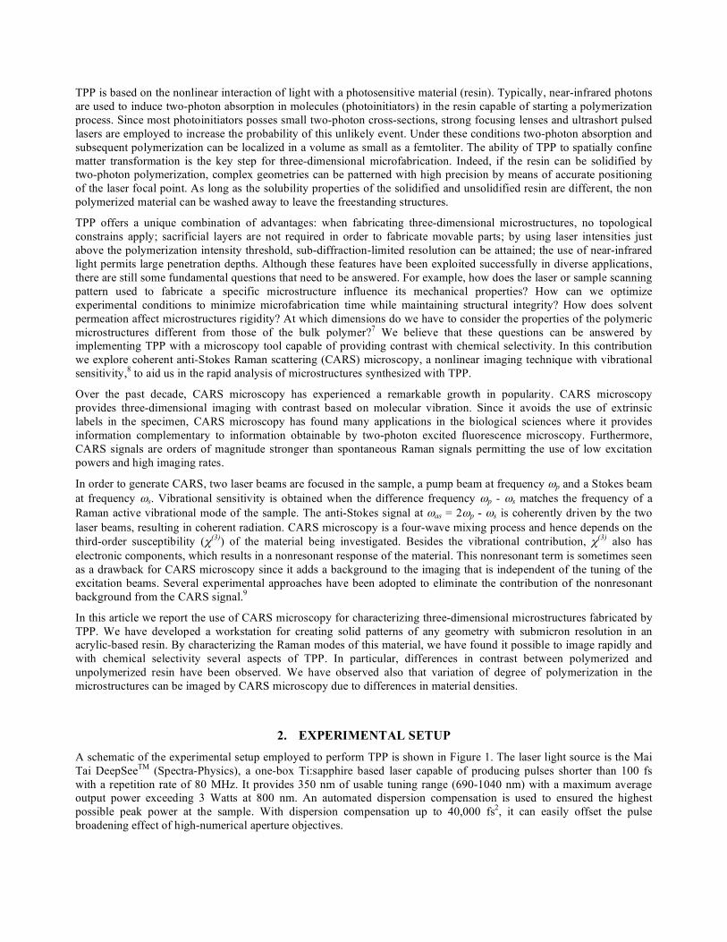
2. EXPERIMENTAL SETUP A schematic of the experimental setup employed to perform TPP is shown in Figure 1. The laser light source is the Mai Tai DeepSeeTM (Spectra-Physics), a one-box Ti:sapphire based laser capable of producing pulses shorter than 100 fs with a repetition rate of 80 MHz. It provides 350 nm of usable tuning range (690-1040 nm) with a maximum average output power exceeding 3 Watts at 800 nm. An automated dispersion compensation is used to ensured the highest possible peak power at the sample. With dispersion compensation up to 40,000 fs2, it can easily offset the pulse broadening effect of high-numerical aperture objectives.
Figure 1. Experimental setup used for TPP. HWP, half-wave plate; GLP, Glan-laser polarizer; M, mirror; M*, beam sampler; AC, autocorrelator; S, shutter; L, lens; SF, spatial filter; DM, dichroic mirror; F, filter; OL, objective lens; TS, translational stage; WL, white light.
A half-wave plate and a polarizer are positioned after the oscillator and are used to variably attenuate the laser output power to the desired input power required by specific experiments. Using a beam sampler, a small portion of the laser beam is directed into a beam diagnostic unit. The laser pulse width and spectrum are characterized by means of an autocorrelator and a spectrometer. The laser beam is then expanded to match or overfill the back aperture of the objective using two lenses. A pinhole is carefully placed at the focal point of the first lens to spatially filter the beam. An electro-mechanical shutter used to control laser exposure times in the sample is placed before this assembly.
A dichroic mirror, which is reflective for near-IR and transparent for visible radiation, deflects the expanded laser beam into an infinity corrected objective that focuses the excitation light in the sample. In all TPP experiments presented in this manuscript, a 40x 0.75 numerical aperture objective was employed (EC Neofluar, Zeiss). The position of the sample in the objective field of view is adjusted by the aid of a computer-controlled stage system. This consists of three high performance stages stacked one on top of each other (XMS, Newport Corp.). The minimum incremental motion, repeatability, and accuracy in the x and y directions are 10 nm, 80 nm, and 200 nm respectively. These features hold true along the entire total travel distance of the stage (50 mm).
Since upon polymerization the resin undergoes a change of state from liquid to solid, wide-field transmission microscopy is used to monitor the process of TPP in real time. The contrast arises from the different densities and hence indices of refraction of the two states (Δn ≈ 0.03 for the resin used in this study). A basic microscope is built by assembling its main components: a source of white light (LED-W-LP, Oriel®), a CCD camera, a video screen, and the requisite optics. It is important to cover the source of white light with a short-pass optical filter to prevent the blue part of the lamp emission spectrum from causing any undesired polymerization in the resin. Furthermore, a long-pass optical filter is placed in front of the CCD camera to prohibit laser back-reflections to reach and saturate the pixels of the camera.
The ability to image the sample while performing TPP is an important feature for a successful fabrication process. It is of utmost importance to anchor the microstructures to the substrates if they are to survive the washing step of the unsolidified resin. The way to ensure this is to start TPP slightly into the substrate at the resin/substrate interface, a task easily achieved with the above described real time monitoring. A schematic of the sample assembly employed in TPP is shown in the inset in Figure 1. The resin is sandwiched between two microscope cover slips. The thickness of the film is
determined by the thickness of the spacer. If microfabrication starts at the resin/substrate interface furthest from the laser entrance, it is imperative to use a spacer thin enough to account for the limitation of the objective working distance.
Software written in LabView is utilized to synchronize the movements of the stages with the action of the shutter trough a single controller/driver (XPS, Newport Corp.). Three-dimensional microstructures can be fabricated by TPP with this software by either vector- or raster-scan mode. Although the vector-scan mode leads to shorter processing time than the raster-scan mode for defining a microstructure since it needs to outline only its surface, not all geometries can be fabricated by vector-scan mode. Indeed, if the volume to surface ratio is too big, shrinkage of the unsolidified resin inside the microstructure can significantly alter its shape overtime.
Details of the CARS microscopy setup employed in this study are described elsewhere.10 Briefly, the second harmonic of a Nd:Vanadate laser (10 ps, 532 nm) is used to pump an intracavity optical parametric oscillator (OPO) that produces 7 ps pulses in the range between 760 nm and 960 nm. In order to drive the CARS process, a portion of the remnant fundamental (1064 nm) laser beam is used as the Stokes beam while the radiation of the OPO provides the pump beam. This system provides broad tunability (1000 – 3500 cm-1) with high spectral resolution (1 – 2 cm-1). The Stokes and the pump beams are collinearly combined and sent into a commercial laser scanning microscope. The beams are focused in the sample by a high numerical aperture objective (40x, 1.15 NA water immersion). Forward CARS signal is collected through a condenser and detected with a photomultiplier tube. Bandpass filters with 40 nm bandwidth are used before the detector. The center wavelengths of the filters were chosen depending on the signal spectral range.
Raman spectra were recorded with a micro Raman spectrometer (M1000, Renishaw). A 0.75 numerical objective is used to focus 5 mW of 781 nm light onto the sample. Each spectrum corresponds to 120 seconds integration time.
3. MATERIALS
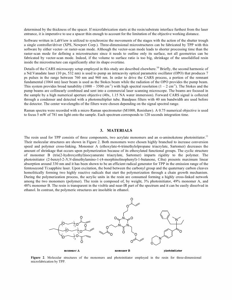
The resin used for TPP consists of three components, two acrylate monomers and an α-aminoketone photoinitiator.11 Their molecular structures are shown in Figure 2. Both monomers were chosen highly branched to increase conversion speed and polymer cross-linking. Monomer A (ethoxylate-6-trimethylolpropane triacrylate, Sartomer) decreases the amount of shrinkage that occurs upon polymerization because of its ethoxylated functional groups. The cyclic structure of monomer B (tris(2-hydroxyethyl)isocyanurate triacrylate, Sartomer) imparts rigidity to the polymer. The photoinitiator (2-benzyl-2-N,N-dimethylamino-1-(4-morphinolinophenyl)-1-butanone, Ciba) presents maximum linear absorption around 330 nm and it has been shown to be an efficient radical generator for TPP in the emission range of the femtosecond Ti:sapphire laser. Upon excitation, the bond between the carbonyl group and the quaternary carbon cleaves homolitically forming two highly reactive radicals that start the polymerization through a chain growth mechanism. During the polymerization process, the acrylic units in the resin are consumed forming a highly cross-linked network among the two monomers (polymer). The resin is composed of, by weight, 3% photoinitiator, 49% monomer A, and 48% monomer B. The resin is transparent in the visible and near-IR part of the spectrum and it can be easily dissolved in ethanol. In contrast, the polymeric structures are insoluble in ethanol.
Figure 2. Molecular structures of the monomers and photoinitiator employed in the resin for three-dimensional microfabrication by TPP.
4. RESULTS 4.1 Two- and three-dimensional microstructures fabricated by TPP
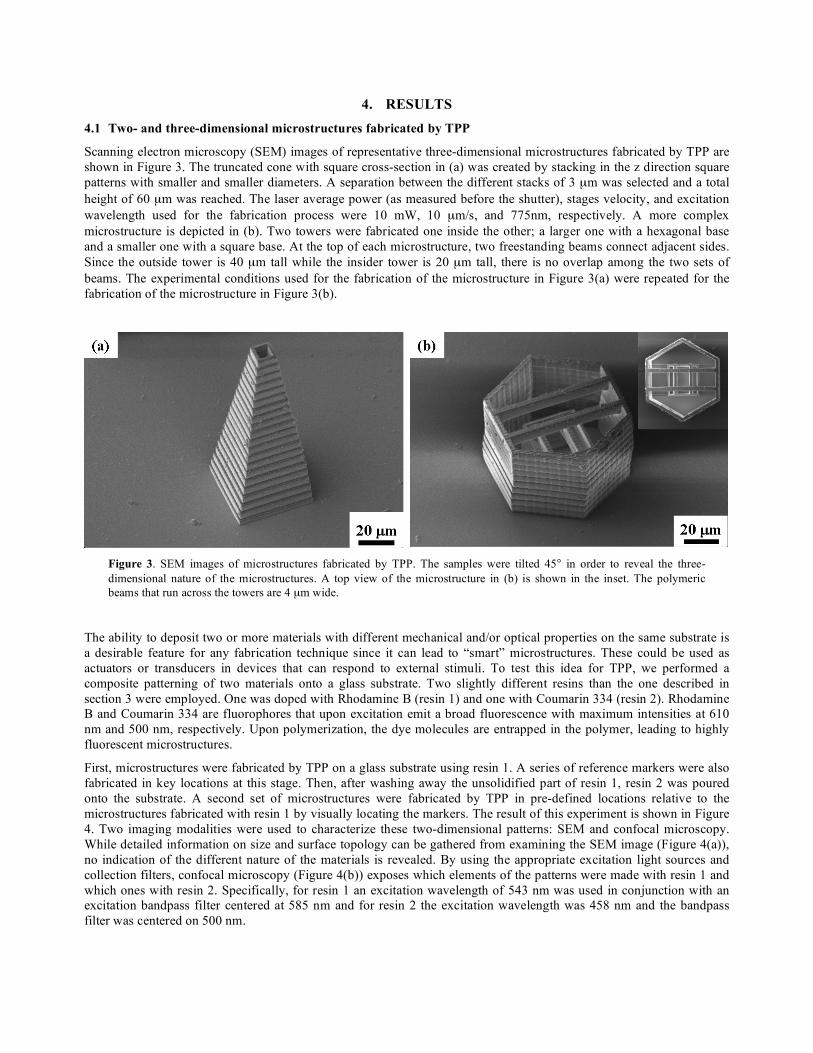
Scanning electron microscopy (SEM) images of representative three-dimensional microstructures fabricated by TPP are shown in Figure 3. The truncated cone with square cross-section in (a) was created by stacking in the z direction square patterns with smaller and smaller diameters. A separation between the different stacks of 3 µm was selected and a total height of 60 µm was reached. The laser average power (as measured before the shutter), stages velocity, and excitation wavelength used for the fabrication process were 10 mW, 10 µm/s, and 775nm, respectively. A more complex microstructure is depicted in (b). Two towers were fabricated one inside the other; a larger one with a hexagonal base and a smaller one with a square base. At the top of each microstructure, two freestanding beams connect adjacent sides. Since the outside tower is 40 µm tall while the insider tower is 20 µm tall, there is no overlap among the two sets of beams. The experimental conditions used for the fabrication of the microstructure in Figure 3(a) were repeated for the fabrication of the microstructure in Figure 3(b).
Figure 3. SEM images of microstructures fabricated by TPP. The samples were tilted 45° in order to reveal the three-dimensional nature of the microstructures. A top view of the microstructure in (b) is shown in the inset. The polymeric beams that run across the towers are 4 µm wide.
The ability to deposit two or more materials with different mechanical and/or optical properties on the same substrate is a desirable feature for any fabrication technique since it can lead to “smart” microstructures. These could be used as actuators or transducers in devices that can respond to external stimuli. To test this idea for TPP, we performed a composite patterning of two materials onto a glass substrate. Two slightly different resins than the one described in section 3 were employed. One was doped with Rhodamine B (resin 1) and one with Coumarin 334 (resin 2). Rhodamine B and Coumarin 334 are fluorophores that upon excitation emit a broad fluorescence with maximum intensities at 610 nm and 500 nm, respectively. Upon polymerization, the dye molecules are entrapped in the polymer, leading to highly fluorescent microstructures.
First, microstructures were fabricated by TPP on a glass substrate using resin 1. A series of reference markers were also fabricated in key locations at this stage. Then, after washing away the unsolidified part of resin 1, resin 2 was poured onto the substrate. A second set of microstructures were fabricated by TPP in pre-defined locations relative to the microstructures fabricated with resin 1 by visually locating the markers. The result of this experiment is shown in Figure 4. Two imaging modalities were used to characterize these two-dimensional patterns: SEM and confocal microscopy. While detailed information on size and surface topology can be gathered from examining the SEM image (Figure 4(a)), no indication of the different nature of the materials is revealed. By using the appropriate excitation light sources and collection filters, confocal microscopy (Figure 4(b)) exposes which elements of the patterns were made with resin 1 and which ones with resin 2. Specifically, for resin 1 an excitation wavelength of 543 nm was used in conjunction with an excitation bandpass filter centered at 585 nm and for resin 2 the excitation wavelength was 458 nm and the bandpass filter was centered on 500 nm.
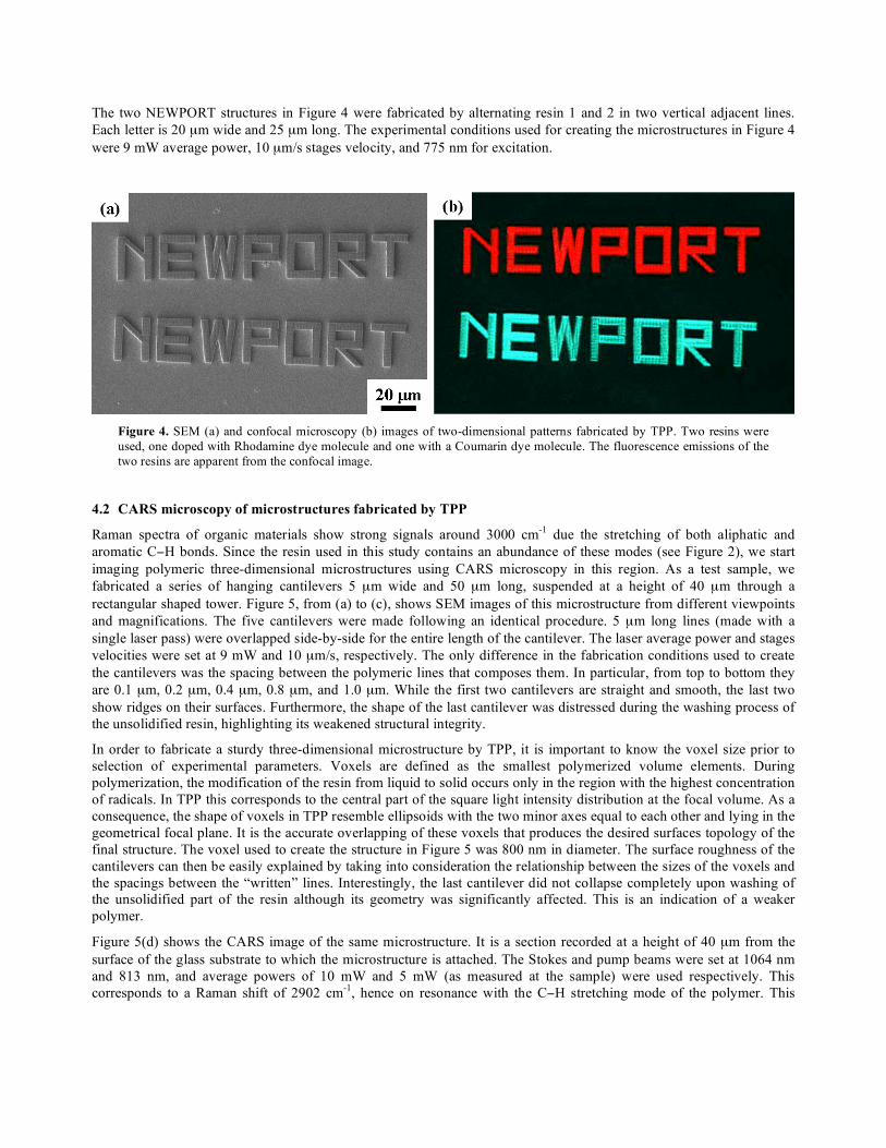
The two NEWPORT structures in Figure 4 were fabricated by alternating resin 1 and 2 in two vertical adjacent lines. Each letter is 20 µm wide and 25 µm long. The experimental conditions used for creating the microstructures in Figure 4 were 9 mW average power, 10 µm/s stages velocity, and 775 nm for excitation.
Figure 4. SEM (a) and confocal microscopy (b) images of two-dimensional patterns fabricated by TPP. Two resins were used, one doped with Rhodamine dye molecule and one with a Coumarin dye molecule. The fluorescence emissions of the two resins are apparent from the confocal image.
4.2 CARS microscopy of microstructures fabricated by TPP
Raman spectra of organic materials show strong signals around 3000 cm-1 due the stretching of both aliphatic and aromatic C−H bonds. Since the resin used in this study contains an abundance of these modes (see Figure 2), we start imaging polymeric three-dimensional microstructures using CARS microscopy in this region. As a test sample, we fabricated a series of hanging cantilevers 5 µm wide and 50 µm long, suspended at a height of 40 µm through a rectangular shaped tower. Figure 5, from (a) to (c), shows SEM images of this microstructure from different viewpoints and magnifications. The five cantilevers were made following an identical procedure. 5 µm long lines (made with a single laser pass) were overlapped side-by-side for the entire length of the cantilever. The laser average power and stages velocities were set at 9 mW and 10 µm/s, respectively. The only difference in the fabrication conditions used to create the cantilevers was the spacing between the polymeric lines that composes them. In particular, from top to bottom they are 0.1 µm, 0.2 µm, 0.4 µm, 0.8 µm, and 1.0 µm. While the first two cantilevers are straight and smooth, the last two show ridges on their surfaces. Furthermore, the shape of the last cantilever was distressed during the washing process of the unsolidified resin, highlighting its weakened structural integrity.
In order to fabricate a sturdy three-dimensional microstructure by TPP, it is important to know the voxel size prior to selection of experimental parameters. Voxels are defined as the smallest polymerized volume elements. During polymerization, the modification of the resin from liquid to solid occurs only in the region with the highest concentration of radicals. In TPP this corresponds to the central part of the square light intensity distribution at the focal volume. As a consequence, the shape of voxels in TPP resemble ellipsoids with the two minor axes equal to each other and lying in the geometrical focal plane. It is the accurate overlapping of these voxels that produces the desired surfaces topology of the final structure. The voxel used to create the structure in Figure 5 was 800 nm in diameter. The surface roughness of the cantilevers can then be easily explained by taking into consideration the relationship between the sizes of the voxels and the spacings between the “written” lines. Interestingly, the last cantilever did not collapse completely upon washing of the unsolidified part of the resin although its geometry was significantly affected. This is an indication of a weaker polymer.
Figure 5(d) shows the CARS image of the same microstructure. It is a section recorded at a height of 40 µm from the surface of the glass substrate to which the microstructure is attached. The Stokes and pump beams were set at 1064 nm and 813 nm, and average powers of 10 mW and 5 mW (as measured at the sample) were used respectively. This corresponds to a Raman shift of 2902 cm-1, hence on resonance with the C−H stretching mode of the polymer. This
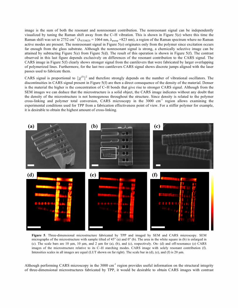
image is the sum of both the resonant and nonresonant contribution. The nonresonant signal can be independently visualized by tuning the Raman shift away from the C−H vibration. This is shown in Figure 5(e) where this time the Raman shift was set to 2752 cm-1 (λSTOKES = 1064 nm, λpump =823 nm), a region of the Raman spectrum where no Raman active modes are present. The nonresonant signal in Figure 5(e) originates only from the polymer since excitation occurs far enough from the glass substrate. Although the nonresonant signal is strong, a chemically selective image can be attained by subtracting Figure 5(e) from Figure 5(d). The result of this operation is shown in Figure 5(f). The contrast observed in this last figure depends exclusively on differences of the resonant contribution to the CARS signal. The CARS image in Figure 5(f) clearly shows stronger signal from the cantilevers that were fabricated by larger overlapping of polymerized lines. Furthermore, for the last two cantilevers CARS signal shows discrete jumps aligned with the laser passes used to fabricate them.
CARS signal is proportional to χ(3)2 and therefore strongly depends on the number of vibrational oscillators. The discontinuities in CARS signal present in Figure 5(f) are then a direct consequence of the density of the material. Denser is the material the higher is the concentration of C−H bonds that give rise to stronger CARS signal. Although from the SEM images we can deduce that the microstructure is a solid object, the CARS image indicates without any doubt that the density of the microstructure is not homogenous throughout the structure. Since density is related to the polymer cross-linking and polymer total conversion, CARS microscopy in the 3000 cm-1 region allows examining the experimental conditions used for TPP from a fabrication effectiveness point of view. For a stiffer polymer for example, it is desirable to obtain the highest amount of cross-linking.
Figure 5. Three-dimensional microstructure fabricated by TPP and imaged by SEM and CARS microscopy. SEM micrographs of the microstructure with sample tilted of 45° (a) and 0° (b). The area in the white square in (b) is enlarged in (c). The scale bars are 10 µm, 10 µm, and 2 µm for (a), (b), and (c), respectively. On- (d) and off-resonance (e) CARS images of the microstructure relative to its C−H starching modes. CARS image with solely resonant contribution (f). Intensities scales in all images are equal (LUT shown on far right). The scale bar in (d), (e), and (f) is 20 µm.
Although performing CARS microscopy in the 3000 cm-1 region provides useful information on the structural integrity of three-dimensional microstructures fabricated by TPP, it would be desirable to obtain CARS images with contrast

based on the chemical differences between the polymerized and unpolymerized parts of the sample. In order to test this possibility, we first collected the Raman spectra of the resin before and after polymerization. Two films of the resin used in TPP were cast between glass cover slips with 100 µm thick spacers. One film was completely polymerized by flood UV irradiation while the other one was left in the unpolymerized state. Figure 6 shows the Raman spectra of these films in the region from 1560 cm-1 to 1750 cm-1. Three bands are observed, one at 1720 cm-1 due to the carbonyl vibration, a second one at 1635 cm-1 due to the carbon-carbon double bond vibration, and lastly, one at 1590 cm-1 due to ring vibration. While the intensity of the ring and carbonyl signals is not affected by polymerization, a decrease in the carbon-carbon double bond signal is observed. This is consistent with the process of radical polymerization, where carbon-carbon double bonds are depleted in time creating carbon-carbon single bonds. It is through these newly formed bonds among the branches of monomers that the polymer is formed.
Figure 6. Raman spectrum of the unpolymerized (straight line) and polymerized (dashed line) resin used in TPP. Integration time was 120 s long, and the excitation wavelength was 681 nm. The modes of each band are assigned.
Figure 7. CARS spectrum of the unpolymerized (straight line) and polymerized (dashed line) resin. The Stokes beam was tuned while the pump beam was kept constant. The vertical lines are a guide to the eye and correspond to the three Raman modes presented by the material used for TPP at 1590 cm-1, 1635 cm-1, and 1720 cm-1.
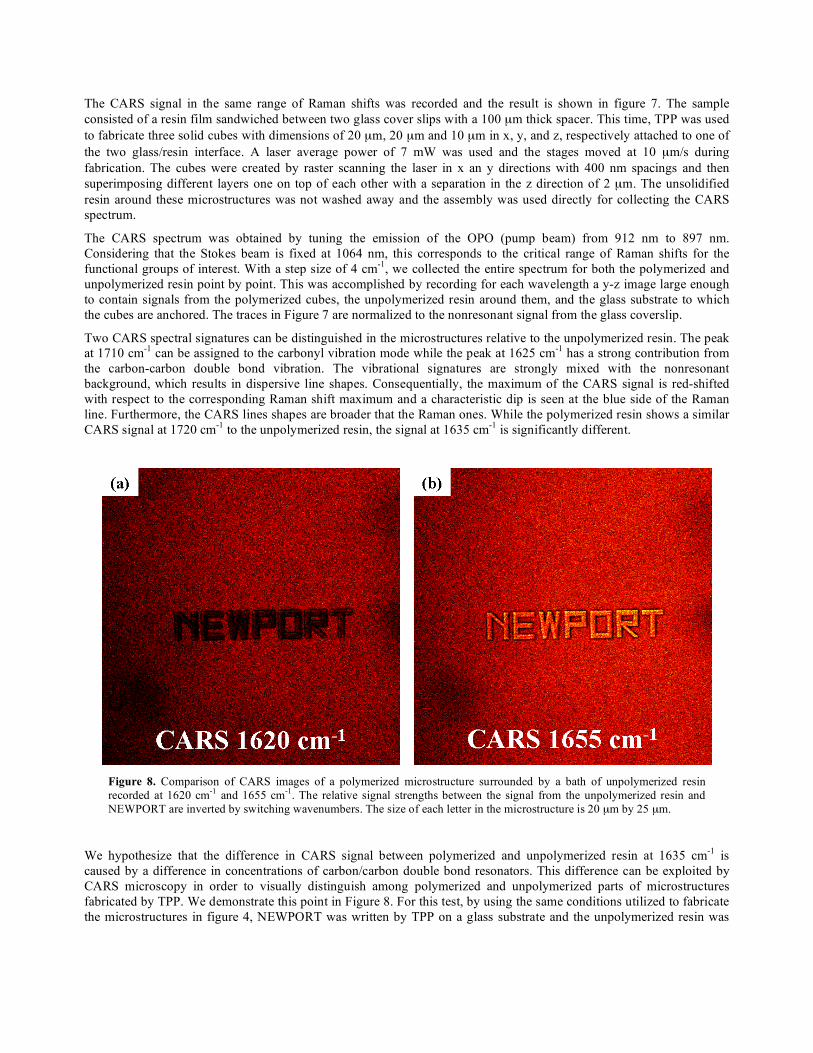
The CARS signal in the same range of Raman shifts was recorded and the result is shown in figure 7. The sample consisted of a resin film sandwiched between two glass cover slips with a 100 µm thick spacer. This time, TPP was used to fabricate three solid cubes with dimensions of 20 µm, 20 µm and 10 µm in x, y, and z, respectively attached to one of the two glass/resin interface. A laser average power of 7 mW was used and the stages moved at 10 µm/s during fabrication. The cubes were created by raster scanning the laser in x an y directions with 400 nm spacings and then superimposing different layers one on top of each other with a separation in the z direction of 2 µm. The unsolidified resin around these microstructures was not washed away and the assembly was used directly for collecting the CARS spectrum.
The CARS spectrum was obtained by tuning the emission of the OPO (pump beam) from 912 nm to 897 nm. Considering that the Stokes beam is fixed at 1064 nm, this corresponds to the critical range of Raman shifts for the functional groups of interest. With a step size of 4 cm-1, we collected the entire spectrum for both the polymerized and unpolymerized resin point by point. This was accomplished by recording for each wavelength a y-z image large enough to contain signals from the polymerized cubes, the unpolymerized resin around them, and the glass substrate to which the cubes are anchored. The traces in Figure 7 are normalized to the nonresonant signal from the glass coverslip.
Two CARS spectral signatures can be distinguished in the microstructures relative to the unpolymerized resin. The peak at 1710 cm-1 can be assigned to the carbonyl vibration mode while the peak at 1625 cm-1 has a strong contribution from the carbon-carbon double bond vibration. The vibrational signatures are strongly mixed with the nonresonant background, which results in dispersive line shapes. Consequentially, the maximum of the CARS signal is red-shifted with respect to the corresponding Raman shift maximum and a characteristic dip is seen at the blue side of the Raman line. Furthermore, the CARS lines shapes are broader that the Raman ones. While the polymerized resin shows a similar CARS signal at 1720 cm-1 to the unpolymerized resin, the signal at 1635 cm-1 is significantly different.
Figure 8. Comparison of CARS images of a polymerized microstructure surrounded by a bath of unpolymerized resin recorded at 1620 cm-1 and 1655 cm-1. The relative signal strengths between the signal from the unpolymerized resin and NEWPORT are inverted by switching wavenumbers. The size of each letter in the microstructure is 20 µm by 25 µm.
We hypothesize that the difference in CARS signal between polymerized and unpolymerized resin at 1635 cm-1 is caused by a difference in concentrations of carbon/carbon double bond resonators. This difference can be exploited by CARS microscopy in order to visually distinguish among polymerized and unpolymerized parts of microstructures fabricated by TPP. We demonstrate this point in Figure 8. For this test, by using the same conditions utilized to fabricate the microstructures in figure 4, NEWPORT was written by TPP on a glass substrate and the unpolymerized resin was
left around the two-dimensional patterns. Two images were recorded, one by tuning the excitation lasers so to excite a Raman shift at 1620 cm-1 (a), and one by tuning the excitation lasers so to excite a Raman shift at 1655 cm-1. At these two Stokes shifts we have different CARS intensity signals for the polymerized and unpolymerized resin (figure 7). At 1620 cm-1, the signal from the unpolymerized resin is stronger that the signal from the polymerized resin, while at 1655 cm-1 the situation is reversed. The images in Figure 8 unmistakably illustrate this phenomenon. In (a) the background, the unpolymerized resin, is brighter that the polymerized microstructure. In (b), NEWPORT is brighter than the background.
5. CONCLUSIONS We have demonstrated the use of CARS imaging for the microscopic characterization of three-dimensional microstructures fabricated by TPP. The resin used in this study permits analysis with low laser average power avoiding melting and/or modification of the sample while imaging. Structural information can be retrieved by using the strong signal generated in the 3000 cm-1 region by the abundant C−H stretching modes, while distributions of carbon-carbon double bonds allows for chemical specificity in imaging. This technique provides the ability to distinguish polymerized and unpolymerized resin with high spatial resolution.
REFERENCES 1 Y. Xia, G. M. Whitesides, “Soft Lithography,” Ann. Rev. Mat. Sci. 28, 153-184 (1998). 2 C. N. LaFratta, J. T. Fourkas, T. Baldacchini, R. A. Farrer, “Multiphoton Fabrication,” Angew. Chem. Int. Ed. 46, 6238-6258 (2004). 3 R. A. Farrer, C. N. LaFratta, L. Li, J. Praino, M. J. Naughton, B. E. A. Saleh, M. C. Teich, J. T. Fourkas, “Selective Functionalization of 3-D Polymer Microstructures,” JACS, 128, 1796-1797 (2006). 4 N. Tetrault, G. von Freymann, M. Deubel, M. Hermatschweiler, F. Perez-Willard, S. John, M. Wegener, G. A. Ozin, ”New Route to Three-Dimensional Photonic Bandgap Materials: Silicon Double Inversion of Polymer Templates,” Adv. Mater. 18, 457-460 (2006). 5 A. Osvianikov, B. Chichkov, P. Mente, N. A. Monteiro-Riviere, A. Doraiswaimy, R. J. Narayan, “Two-Photon Polymeryzation of Polymer-Ceramic Hybrid Materials for Transdermal Drug Delivery,” Int. J. Appl. Ceram. Technol. 4, 22-29 (2007). 6 P. Tayalia, C. R. Mendonca, T. Baldacchini, D. J. Mooney, E. Mazur ,“3D Cell-Migration Studies using Two- Photon Engineered Polymer Scaffolds,” Adv. Mater. 20, 4494-4498 (2008). 7 S. Nakanishi, S. Shoji, S. Kawata, H.-B. Sun, “Giant Elasticity of Photopolymer Nanowire,” Appl. Phys. Lett. 91, 0631121-06311213 (2007). 8 C. L. Evans, S. Xie, “Coherent Anti-Stokes Raman Scattering Microscopy: Chemical Imaging for Biology and Medicine,” Annu. Rev. Anal. Chem. 1, 883-909 (2008). 9 M. Muller, A. Zumbusch, “Coherent Anti-Stokes Raman Scattering Microscopy,” ChemPhysChem 8, 2156- 2170 (2007). 10 V. V. Krishnamachari, E. O. Potma, “Multi-Dimensional differential Imaging with FE-CARS Microscopy,“ Vibrat. Spectrosc. (2008), doi:10.1016/j.vibspec.2008.07.009. 11 T. Baldacchini, C. N. LaFratta, R. A. Farrer, M. C. Teich, B. E. A. Saleh, M. J. Naughton, J. T. Fourkas, “Acrylic-Based Resin with Favorable Properties Three-Dimensional Two-Photon Polymerization,” J. App. Phys. 95, 6072-6076 (2004).