Embed Size (px)
Citation preview

1
CHARACTERIZATION OF DRY-STACK 1
INTERLOCKING COMPRESSED EARTH BLOCKS 2
Thomas Sturm 3
PhD Student, ISISE, University of Minho, Guimarães, Portugal 4
6
Luís F. Ramos 7
Assistant Professor, ISISE, University of Minho, Guimarães, Portugal 8
10
Paulo B. Lourenço 11
Professor, ISISE, University of Minho, Guimarães, Portugal 12
14
ABSTRACT 15
Earth has been a traditional building material to construct houses in Africa. One of the most common techniques 16
is the use of sun dried or kiln fired adobe bricks with mud mortar. Fired bricks are the main cause for deforestation 17
in countries like Malawi. Although this technique is low-cost, the bricks vary largely in shape, strength and 18
durability. This leads to weak houses which suffer considerable damage during floods and seismic events. One 19
solution is the use of dry-stack masonry with stabilized interlocking compressed earth blocks (ICEB). This 20
technology has the potential of substituting the current bricks by a more sustainable kind of block. This study was 21
made in the context of the HiLoTec project, which focuses on houses in rural areas of developing countries. For 22
this study, Malawi was chosen for a case study. This paper presents the experimental results of tests made with 23
dry-stack ICEBs. Soil samples from Malawi were taken and studied. Since the experimental campaign could not 24
be carried out in Malawi, a homogenization process of Portuguese soil was made to produce ICEBs at the 25
2
University of Minho, Portugal. Then, the compression and tensile strength of the materials was determined via 1
small cylinder samples. Subsequently, the compression and flexural strength of units were determined. Finally, 2
tests to determine the compressive strength of both prisms and masonry wallets and to determine the initial shear 3
strength of the dry interfaces were carried out. This work provides valuable data for low-cost eco-efficient housing. 4
KEYWORDS: Compressed earth blocks; dry-stack; masonry; interlocking; testing. 5
Introduction 6
In many African regions, the use of hand moulded unfired or fired earth blocks is still widespread. 7
Although this technique is cheap and allows the self-construction, the bricks vary largely in shape, 8
strength and durability. Due to the unregularly shapes, also thick mortar joints of several centimetres are 9
necessary. Furthermore, the use of wood kilns to fire the bricks has led to widespread deforestation in 10
countries such as Malawi (Zingano 2005). 11
Taking into account the growing population in this region, and therefore the demand for housing, it 12
seems very unlikely, both technically and economically, that this demand will be only met with 13
industrialized building materials, such as concrete or steel, in the next decades. For this purpose there 14
are simply neither enough production capabilities nor resources (Minke, 2006). Earth will continue to 15
be the primary building material and self-construction a usual practice for communities in developing 16
countries, where modern materials and technical supervision is simply too costly. 17
In the middle of the 20th century, new kinds of unfired blocks were developed. These blocks are similar 18
to unfired earth blocks made in moulds, with the difference that the earth is compressed in the mould 19
mechanically before drying, and hence they carry the name of 'compressed earth blocks' (CEB). This 20
allows a higher compacting of the soil, resulting in blocks with regular shape and higher strength and 21
durability properties without using fuel to burn the bricks (Zingano 2005). These kind of blocks have 22
experienced an increased popularity in some African countries due to their perceived superiority over 23
traditional earth materials (Lyamuya and Arch 2013). Even though CEBs provided a cost effective and 24
environmentally-friendly alternative to traditional blocks, some disadvantages remained: the need of 25

3
skilled masonry labour and the large thickness of the mortar joints (usually cement based) (Uzoegbo 1
and Ngowi 2004). 2
In recent decades, the CEBs have evolved from solid blocks to more complex shapes. The incorporation 3
of perforations make the blocks lighter and allow the use of reinforcements. A more recent feature is the 4
introduction of indentations (male) and their female counterpart into the blocks, which allows for a fast 5
and easy way of constructing (Uzoegbo 2001). With this interlocking compressed earth blocks (ICEB) 6
the masonry can be dry-stack and the construction process has been simplified, as the blocks lock 7
themselves during the erection of the walls. This makes them ideal for self-construction and eliminates 8
the use of mortar joints, thus reducing the final building cost (UN HABITAT 2009). This construction 9
concept in conjunction with adequate details, such as strong foundations, ring beams and overhanging 10
roofs, has the potential of offering new possibilities for affordable, safe and quality housing in these 11
regions. 12
A case study in Malawi 13
As a contribution to this subject, this work focuses on the study of the strength of dry-stack ICEB 14
masonry. The aim is to characterize the mechanical properties of this system for its use in developing 15
countries with moderate seismicity. All the work took place within the HiLoTec (HLT) project, which 16
is a cooperative action between the major Portuguese contractor Mota-Engil and the University of Minho 17
(UM). The HLT project has been dedicated to a social concept for innovative small houses in rural areas 18
of developing countries, favouring the adoption of local materials and with the main premise of being 19
dedicated to self-construction. The selected target group are families of rural areas, since they have less 20
access to the 'good practice' knowhow and can afford only less expensive materials in comparison to 21
urban families. 22
Because social and economic conditions can vary largely from one region to another, a reference country 23
for a case study had to be chosen. This work aims at the study of self-made ICEBs by local rural 24
communities in countries with the following conditions: (i) they are developing countries; (ii) self-25
construction is usual; (iii) earth construction is common; (iv) there is the need for improvement of the 26
4
housing condition of low income families. Although several countries in Africa, Asia or Latin America 1
might have been good candidates, only one could be chosen for the case study. The assumption is that 2
from the case study the results of this work can be extrapolated to other regions with similar conditions 3
to that of the case study country. 4
Finally, Malawi was chosen as the reference country, since it fulfils the desired characteristics and has 5
only moderate seismicity (details about Malawi can be found in USAID, 2004). 6
Block geometry 7
The ICEB used in this project has been designed and manufactured within the HLT project. The ICEB 8
was inspired by the Rhino Block (Gate, 2005), but it is slightly smaller in size. Also the vertical holes 9
of the Rhino Block which are not part of the interlocking have been left out, since these high level of 10
details can lead to weak flanges in the block. To produce the new ICEB, a mould was made and adapted 11
to the Belgian Testaram® (Appro 2014). 12
This ICEB allows dry-stacking masonry with running bond arrangement using single or double-leaf 13
walls. The interlocking is such that locking of the blocks in the two main horizontal directions is present. 14
The overall dimensions of the block and some possible arrangements are shown in Fig. 1. The 15
thicknesses of the walls are in accordance with the NZS4299 (1998). 16
The shape chosen for the ICEB was such that dry-stacking is possible with running bond, using single 17
or double-leaf walls, and such that locking in the out-of-plane direction is present. The overall 18
dimensions of the block and some possible arrangements are shown in Fig. 1. The idea behind the use 19
of double-leaf walls is to provide stronger external walls and lighter masonry (single-leaf) for the interior 20
walls. In case of the double leaf walls, every five courses header blocks can be laid in the perpendicular 21
direction to the wall to improve the out-of-plane behaviour and the stability of the wall to vertical loads, 22
see Fig. 1c. 23
5
Research Objectives 1
The current work focuses on rural houses for central Africa. Samples were gathered in Malawi to 2
determine the soil characteristics. The soils have low clay content (~5%) and a stabilization of 9% of 3
cement in weight was needed to achieve a compressive strength over 2 MPa, as it was also the case for 4
Reddy and Gupta (2005). Since a large quantity of soil was needed for the experimental campaign with 5
the proposed ICEB, a local Portuguese soil with similar characteristics was used instead. To obtain a 6
similar compressive strength, the Portuguese soil had to be stabilized with 5% of cement (CEM II/B-L 7
32.5N) and 10% of kaolin. After production, the blocks were first cured under black nylon films for 8
seven days and then got air dried until they reached an age of 28 days. 9
Kaolin had to be added to give the Portuguese soil a similar workability when compared to the Malawi 10
soil. It is important to mention that workability is not relevant when considering the strength of CEB 11
masonry, but it is a fundamental parameter during production. A low workability leads to weak green 12
blocks, which can easily break when they are taken from the pressing equipment. 13
The aim of this work is to present a comprehensive experimental campaign that characterizes ICEB 14
masonry from its basic material properties (stabilised soil), to the unit (the blocks) and up to the masonry 15
(prism, wallets, dry interface). The comparison of the strength of single ICEBs with its masonry gives 16
an insight in the relation these measures have. The study of the behaviour of the dry interface is presented 17
for the first time and is important for future testing and to take into account in numerical modelling. 18
Experimental Testing Campaign 19
The test campaign carried out can be divided into four phases according to the size of the samples and 20
the characteristics to be studied. The results of these tests contribute to the mechanical characterization 21
of the material used (soil), the ICEB (units) and the masonry prims and wallets, see Table 1. 22

6
In all compression tests, the compressive stress was obtained by dividing the vertical load by the net 1
area of the cross section of the specimen and the Young’s modulus (𝐸) was obtained as the tangent curve 2
between 40% and 70% of the peak stress. 3
Small cylinder samples 4
As a way of characterizing the material properties of the stabilized soil to produce CEBs and for quality 5
control reasons, samples of the soil mix were taken in each block production day. For each day at least 6
6 small cylinder specimens were made. During production samples were compressed with a pressure of 7
2 MPa, which replicates the effect of the pressing machine to make the blocks. The resulting samples 8
had an average length of 65 mm and 50 mm diameter. 9
Both the compression tests and the indirect tensile tests were carried out in a 50 kN electro-mechanic 10
testing machine under displacement control. Due to the small size of the specimens, displacements were 11
measured internally by the machine. 12
Compression tests 13
The samples were tested under direct compression just after production (green stage) and at an age of 7, 14
14 and 28 days to determine the compressive strength of the soil (𝑓𝑐). Cylinder samples have already 15
been used by Chan and Low (2010), which obtained compressive strengths between 1.20 MPa to 1.39 16
MPa for 5% and 2.16 MPa to 2.67 MPa for 10% cement stabilised earth samples with soils similar to 17
the ones used in this investigation. Yetgin et al. (2008) and Galán Marín et al. (2010) have obtained 18
compressive strengths (fc) ranging from 2 MPa to 3.5 MPa for different natural fibre reinforced adobes 19
with cubic specimens and 2.2 MPa to 4.4 MPa for natural polymer stabilised adobes with rectangular 20
specimens, respectively. Cubic and rectangular specimens are known to show higher strengths than 21
slender cylindrical samples. 22
Indirect tension tests 23
The tensile strength of the stabilized soil was determined with the indirect tensile test method proposed 24
by the EN13286-42 (2003), even though this code focuses on the determination of the tensile strength 25

7
of hydraulically bound mixes. This test determines the tensile strength (𝑓𝑖𝑡) by applying a vertical force 1
on two parallel faces of a horizontally laid cylinder. The specimen then splits vertically along its length 2
and the tensile strength can be determined indirectly with the expression from the EN13286-42 (2003): 3
DH
Ffit
**
*2
(1) 4
where 𝑓𝑖𝑡 is the indirect tensile strength, 𝐹 is the maximum applied force, 𝐻 is the length of the specimen 5
and 𝐷 is the diameter of the specimen. 6
The test specimens had an age of 28 days and the displacement rate used during the test was equal to 7
0.002 mm/s. Related to this type of test, Yetgin et al. (2008) have obtained tensile strengths ranging 8
between 0.4 MPa and 0.75 MPa. 9
Units 10
Compressive strength 11
Compressive strength has become a basic and universally accepted characteristic for measuring the 12
quality of masonry units (Morel et al. 2007). A common criterion adopted by codes or guidelines of 13
earth construction is to demand compressive strengths higher or equal to 2 MPa (ASTM D1633-00 2007; 14
ARS674 1996; DL 2009; CSIRO 1987; NMAC 2006; AEI 2005; HB195 2002). This compressive 15
strength is often defined as confined compressive strength, whereas unconfined compressive strength 16
(i.e. prisms or walls) is usually only between 0.3 to 0.4 times the value of the unit strength (Uzoegbo 17
and Ngowi 2003). 18
Compressive tests of handmade soil blocks carried out by Browne (2009) typically gave 2 MPa, 19
but machine testing has a history of providing strengths higher than 3.5 MPa (Morel et al. 2007; Piattoni 20
et al. 2001; Kuchena and Usiri 2009). As long as CEBs have compressive strengths over 2 MPa, strength 21
is not viewed as an issue as historical data shows that this is an adequate strength for the application and 22
use of blocks in low rise, low cost housing projects (Browne 2009). Compression tests of single CEB 23
do not differ from those used for other types of bricks. They can be made on a conventional 24

8
concrete/brick compression machine, in which individual units are capped and tested directly between 1
platens (Heath et al. 2009; Morel et al. 2007). 2
The standard followed for this test is the EN 772-1 (2000), for masonry units with peak compressive 3
strength below 10 MPa. The tests were carried out with a hydraulic press under force control with a 4
loading rate of 0.5 kN/s at 7, 14 and 28 days, as the standard HB195 (2002) suggests. For comparison, 5
both CEB made of soil from Malawi and from local soil (Portugal) were tested. Five blocks from Malawi 6
were tested, while six blocks made of Portuguese soil of three production days (18 in total) were tested 7
at each age. 8
Flexural strength 9
The three point bending test is used to determine the tensile strength indirectly, being known as flexural 10
strength (𝑓𝑏𝑓). In this test, the block is laid on two simple supports at it ends and a vertical force is 11
applied in the middle of the block. The tests were carried out in accordance to the EN 772-6 (2001), but 12
with modifications inspired on the HB195 (2002), because the European Standards do not fit the 13
dimensions of the CEB. The vertical load was applied by means of a hydraulic actuator with 14
displacement control at a rate equal to 0.005 mm/s, using a control linear variable differential transducer 15
(LVDT). This LVDT measures the vertical deflection (𝛿) of the block. Additionally, vertical and 16
horizontal measurements of displacement were made with LVDTs attached to the specimen. The 17
flexural strength 𝑓𝑏𝑓 was then calculated as mentioned in HB195 (2002). 18
With this test, Lenci et al. (2012) have obtained average strengths of 0.85 MPa with manually pressed 19
earth blocks and Galán-Marín et al. (2010) obtained strengths between 1.1 and 1.5 MPa for adobes with 20
natural fibres. But the results of this type of test have been disputed, as the Saint Venant principle is not 21
fully verified and the non-linearity is neglected (Morel and Pkla 2002). Despite this fact, this test can 22
also estimate in an indirect way the compressive strength and has been used for CEB in-situ quality 23
control, as an easy setup can be made in which the vertical force needed to achieve failure is about 20 24
times lower than in compression (Morel and Pkla 2002). This is relevant when CEB are being produced 25
in developing countries by small scale CEB manufacturers and self-constructers, since it gives to the 26
9
producers a way to develop a simple quality control method. Morel and Pkla (2002) define a minimum 1
total load of 4 kN for the unit for quality control on manual compression and low cement content CEB. 2
3
Compression tests of masonry specimens 4
Since the proposed ICEB will be dry-stacked, the expected strength should be governed by the properties 5
of the stabilized soil, by the frictional interface between units, by the contact in the interlocking and by 6
geometrical aspects. Compression tests of stacked bond prisms or masonry wallets are frequently used 7
to determine the compression strength of masonry. Both tests were carried out to characterize the impact 8
of the specimen type on the compressive strength, as the stack bonded test is much easier to carry out in 9
developing countries. 10
Masonry prisms 11
The test on masonry prisms (or stacked bond prisms) has the advantage that the specimens are small and 12
that the test is easy to carry out. The obvious disadvantage of the test is that it does not replicate the 13
bond pattern of the masonry. This test followed the ASTM C1314-03b (2003) standard, which defined 14
masonry prisms with at least two units in height and a slenderness ratio between 1.3 and 5.0. This 15
standard defines the compressive strength of masonry (𝑓𝑚𝑝) as the average of the results. Due to the 16
dimensions of the specimens, the result of this test is also referred to as unconfined compressive strength. 17
No capping of the specimens or levelling mortar was needed, since the lower and upper platens of the 18
mould from the pressing machine were used, which have the exact shape of the CEBs top and the bottom 19
surfaces (including interlocking). The force was applied by means of an hydraulic actuator with 20
displacement control with a rate of 0.005 mm/s. Relative displacements were measured between the 21
second and fourth blocks, which corresponds approximately to the middle third of the height, on both 22
longitudinal faces by two LVDTs, and between the middle of the first and the fifth blocks on the 23
transversal faces. 24

10
It should be stressed that Morel et al. (2007) have obtained strengths ranging from 2.3 to 3.1 MPa for 1
unconfined masonry specimens of different sizes. 2
Masonry wallets 3
Single and double-leaf wallets with the proposed ICEB following the EN 1052-1 (1999) standard were 4
adopted. The specimens were 0.84 m in length and 0.84 m in height. This is equivalent to wall specimens 5
of 3 blocks in length and 9 blocks in height. The thickness was 0.14 m for the single-leaf wall and 0.28 m 6
for the double-leaf wall. Two LVDTs were attached vertically to the specimens in the middle third of 7
both longitudinal faces, one horizontally on one of the longitudinal faces and one horizontally in one of 8
the transversal faces. The load was applied by a hydraulic actuator by means of displacement control 9
with a rate equal to 0.015 mm/s. 10
Stiff steel beams of more than 0.3 m in height were placed on top of the specimen to uniformly distribute 11
the vertical load of the actuator. A total of ten specimens were tested. 12
The typical failure mode observed in masonry walls subjected to vertical compression is a vertical split 13
through the walls thickness (Heath et al. 2009). Jayasinghe and Kamaladasa (2007) tested rammed earth 14
panels of 1 m length, 0.16 m thickness and 0.65 m of height made with different soils and 6%, 8% and 15
10% of cement content, obtaining compressive strengths between 1.8 and 3.7 MPa and an average 16
Young’s modulus of around 500 MPa. 17
Dry interface 18
Masonry is often treated as an isotropic material, even if it can exhibit a high orthotropic behaviour, 19
depending on factors such as the unit to mortar strength and the bond arrangement. Dry-stack masonry 20
with ICEB is expected to have an orthotropic behaviour since the block has large vertical perforations 21
and no continuity of the material is given under traction. In addition, under vertical (compressive) 22
loading dry-stack masonry does not behave different than other masonries, although it has no tensile 23
strength due to the lack of mortar bond between units. In the horizontal direction, the shear strength is 24
governed mainly by the friction between the units, i.e. the interface. The Coulomb friction law has long 25
11
been used as a constitutive model of friction interfaces, in which the shear strength is dependent of the 1
initial shear strength (𝑓𝜐0) and the tangent of the internal friction angle (tan αk). Where in continuous 2
materials the initial shear strength might be provided by the cohesion, in ICEB masonry the initial shear 3
strength is expected to be provided by the interlocking, as long as the upward movement is restrained. 4
The results of a dynamic test of an ICEB house (Elvin and Uzoegbo 2011) show that the self-weight of 5
a structure (i.e. walls and roof system) is enough to restrain the upward movement of the blocks in the 6
in-plane direction. 7
Another relevant feature of masonry joints is the so-called dilatancy angle (𝜓), which measures the uplift 8
of one unit over the other upon shearing. The tangent of the dilatancy angle ( tan ) is determined by 9
dividing the vertical displacement (𝛿𝑣) by the horizontal displacement (𝛿ℎ) upon shearing. The dilatancy 10
angle can assume positive or negative values and depends on the confining stress (Lourenço 2008). 11
Usually, the dilatancy angle (tan𝜓) is positive but tends to zero upon increasing shear displacement and 12
increasing normal confining stress (Pluijm 1999). But the results presented in Lourenço and Ramos 13
(2004) demonstrate, that even for the same material, the friction and dilatancy angles are very dependent 14
on the roughness of the joint. In particular, a smooth (polished) surface exhibits very low friction and a 15
rough surface can exhibit a negative non-negligible dilatancy angle. 16
The shear behaviour of this dry-stack masonry was determined through the triplet test according to 17
EN 1052-3 (2002) standard, although modifications had to be made to the proposed setup. The triplet 18
test consists of a three block stacked prisms with mortar joints which is laid horizontally between two 19
roller supports. The prims are horizontally pre-compressed and finally a distributed vertical load is 20
applied on the block in the middle. In absence of mortar joints (bond), it is very difficult to lay the prism 21
horizontally. Therefore, instead of laying the specimen horizontally, the prism was kept standing 22
vertically and the shear load was applied horizontally, in a similar fashion as the EN 1052-4 (2000) 23
suggests. 24
The vertical force was kept constant by means of a force controlled hydraulic actuator. The horizontal 25
force was applied by an actuator under displacement control with a rate equal to 0.007 mm/s. 26

12
Two LVDTs measured the horizontal displacement of the block in the middle at its ends and two LVDTs 1
on each main face measured the vertical displacements. Three tests were made with three different 2
confining loads. The shear strength of an individual sample at each confining stress is determined by 3
dividing the maximum attained shear force by two times the cross sectional area (EN 1052-3, 2002). 4
Afterwards, the results of each individual test can be plotted in terms of the confining stress versus the 5
attained shear strength. The Coulomb friction plane is then obtained by a linear regression of these 6
results, in which the shear strength 𝑓𝑣 is a function of the confining stress: 7
0)tan( vpkv fff (3) 8
where 𝑓𝑝 is the confining stress, 𝑓𝜐0 is the initial shear strength, and tan(∝𝑘) is the tangent of the internal 9
friction angle. 10
Results 11
The results for all the tests are next presented in terms of average value and coefficient of variation 12
(CoV). 13
Small cylinder samples 14
Compressive strength 15
Several tests were carried out at different ages, 21 samples were tested at green stage and an age of 14 16
days, and 39 samples were tested at an age of 7 and 28 days, making a total of 120 samples. The results 17
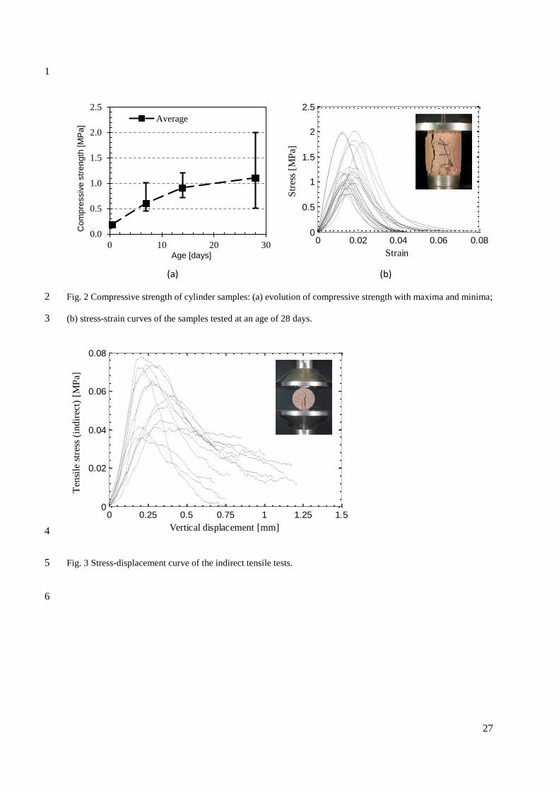
of the compressive tests are summarized in Fig. 2a which shows the evolution of the compressive 18
strength (𝑓𝑐) over a period of 28 days while Fig. 2b shows the stress strain curves of the tested samples 19
at an age of 28 days. As expected, the average maximum compressive strength of the samples increase 20
from around 0.2 MPa to around 1.1 MPa in 28 days, as the cement hardens. The 0.2 MPa compressive 21
strength of the green samples is only related to the cohesion of the soil mix with low influence of the 22
cement (in Fig. 2, the error bars at green stage are too small to be appreciated). From the evolution of 23
13
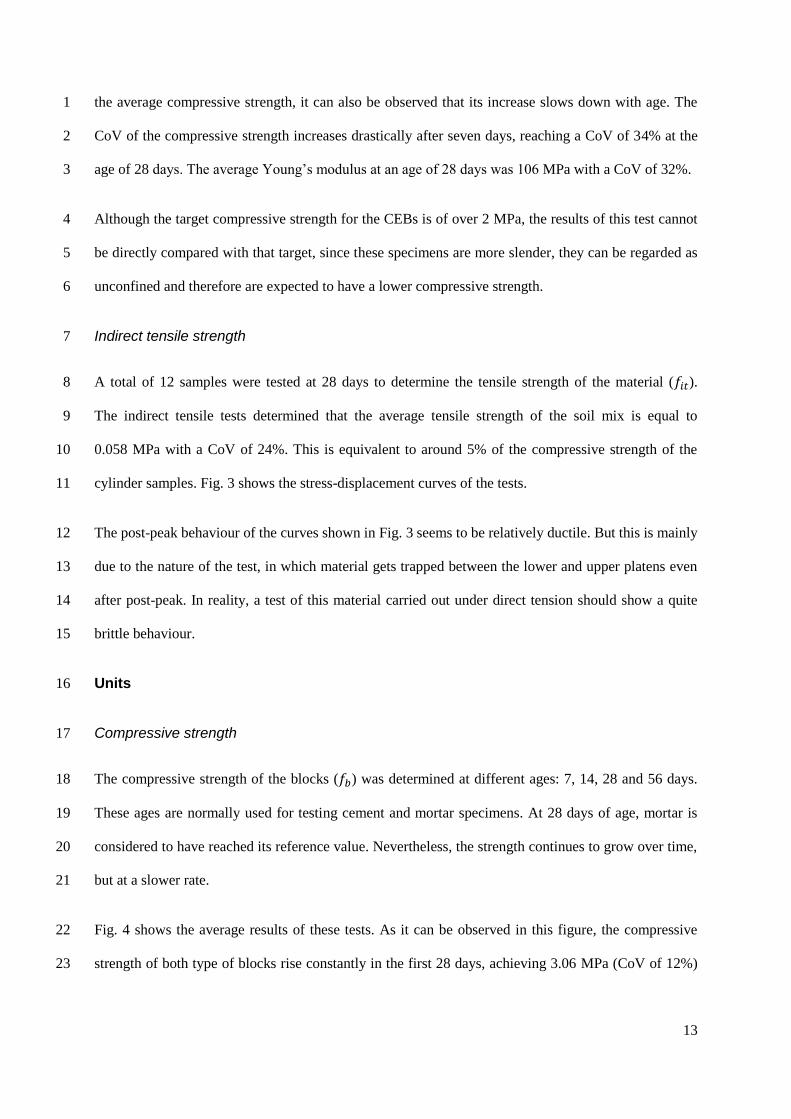
the average compressive strength, it can also be observed that its increase slows down with age. The 1
CoV of the compressive strength increases drastically after seven days, reaching a CoV of 34% at the 2
age of 28 days. The average Young’s modulus at an age of 28 days was 106 MPa with a CoV of 32%. 3
Although the target compressive strength for the CEBs is of over 2 MPa, the results of this test cannot 4
be directly compared with that target, since these specimens are more slender, they can be regarded as 5
unconfined and therefore are expected to have a lower compressive strength. 6
Indirect tensile strength 7
A total of 12 samples were tested at 28 days to determine the tensile strength of the material (𝑓𝑖𝑡). 8
The indirect tensile tests determined that the average tensile strength of the soil mix is equal to 9
0.058 MPa with a CoV of 24%. This is equivalent to around 5% of the compressive strength of the 10
cylinder samples. Fig. 3 shows the stress-displacement curves of the tests. 11
The post-peak behaviour of the curves shown in Fig. 3 seems to be relatively ductile. But this is mainly 12
due to the nature of the test, in which material gets trapped between the lower and upper platens even 13
after post-peak. In reality, a test of this material carried out under direct tension should show a quite 14
brittle behaviour. 15
Units 16
Compressive strength 17
The compressive strength of the blocks (𝑓𝑏) was determined at different ages: 7, 14, 28 and 56 days. 18
These ages are normally used for testing cement and mortar specimens. At 28 days of age, mortar is 19
considered to have reached its reference value. Nevertheless, the strength continues to grow over time, 20
but at a slower rate. 21
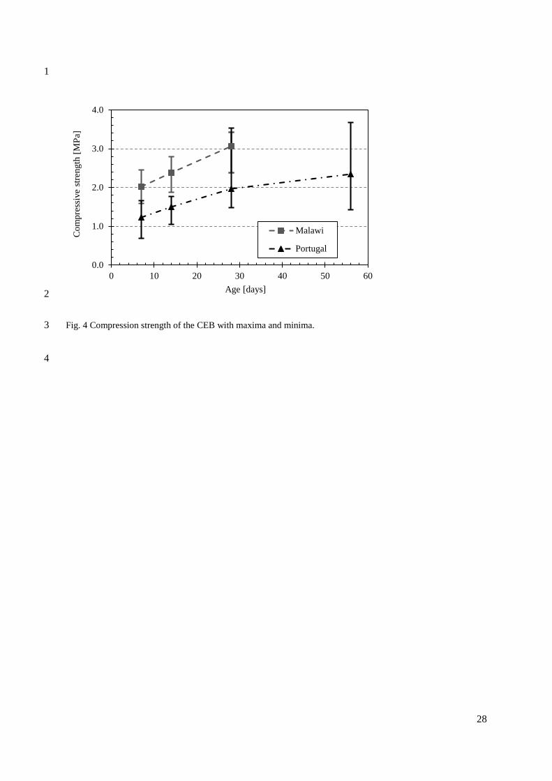
Fig. 4 shows the average results of these tests. As it can be observed in this figure, the compressive 22
strength of both type of blocks rise constantly in the first 28 days, achieving 3.06 MPa (CoV of 12%) 23

14
with the soil from Malawi and 1.96 MPa (CoV of 27%) with the Portuguese soil. Only at an age of 56 1
days, the blocks of Portuguese soil reach an average strength of 2.34 MPa with a CoV of 24%. 2
Even if the results obtained during the homogenization indicated similar strengths of the soils at the 3
material level, the strength of the ICEBs made with the two soils did not have a good correlation, since 4
the Portuguese soil had a lower strength than predicted. Despite of this, the test campaign was continued. 5
Since this project focuses on self-construction, it is also assumed that self-made ICEBs in Malawi might 6
at times have less compressive strength than the ones studied in this case. Therefore, the results of the 7
masonry studies made with the Portuguese blocks can be viewed as a conservative estimate. Moreover, 8
the study of ICEB masonry with the Portuguese block still gives a valuable insight into the behaviour 9
of ICEB masonry in general. 10
The stress-strain curves of the blocks with soil from Malawi at an age of 28 days and of the blocks with 11
the soil from Portugal are shown in Fig. 5. In this figure it can be observed that the blocks with soil from 12
Malawi seem to be more ductile than the ones of soil from Portugal. Also the high dispersion of the 13
results from the Portuguese soil can be clearly appreciated in Fig. 5.b. Due to the small amount of blocks 14
tested with the Malawian soil, it cannot be excluded that the smaller CoV of 12% might not be higher 15
indeed. 16
The average Young’s modulus of the blocks made with Malawian and Portuguese soil was equal to 17
148 MPa and 163 MPa with CoVs of 20% and 30% at an age of 28 days and 56 days, respectively. 18
In Fig. 6 it can be observed that the Young’s modulus and the compressive strength correlate well to 19
each other, although not enough data is available in case of the blocks made with soil from Malawi to 20
assure this statement. 21
Flexural strength 22
Normally, in flexural strength tests the specimen is notched in the middle of the lower side of the block 23
in order to control the plane of fracture, and to capture the fracture energy. Due to the fragile nature of 24
this kind of blocks, it was not possible to make a notch. As the cross section of the blocks is not constant 25

15
along its length (due to the vertical holes), the plane of failure was usually not vertical but diagonal with 1
an angle of approximately 30º from the vertical axis. 2
A total of 12 blocks were tested. The average flexural strength (𝑓𝑏𝑓) determined with the expression 3
given by the HB195 (2002) was equal to 0.21 MPa, which is equivalent to a load of around 730 N, with 4
a CoV of 19%. 5
Masonry specimens 6
Compression of masonry prisms 7
Compressive tests of prisms with 5 dry-stack ICEB units were made. The height of the prisms was equal 8
to 0.47 m. A total of 12 prisms were tested. The resulting stress-strain curves are shown in Fig. 7. The 9
average compressive strength (𝑓𝑚𝑝) of the tests is equal to 0.87 MPa with a CoV of 24%, and the average 10
Young’s modulus was equal to 129 MPa with a CoV of 19%. 11
Bui and Morel (2009) tested rammed earth specimens of 0.4 m of height and with a slenderness ratio of 12
2, obtaining an average compressive strength 0.84 MPa. Even though the typology of the masonries is 13
not the same, it is interesting to observe that the results are of the same range. 14
The failure patterns were similar for all specimens. Fig. 8 summarizes the main observed damages. 15
Spalling in one main faces of one block was generally present, see Fig. 8a. In some cases compression 16
zones formed at the tip or one or more corners broke off, see Fig. 8b and Fig. 8c. In the lateral face, 17
small vertical cracks appeared in the upper blocks and larger cracks in the subsequent lower blocks. It 18
is interesting to notice that the spalling was almost only present on one block, see Fig. 8d. 19
Compression of masonry wallets 20
Compressive tests of single and double-leaf ICEB masonry wallets were carried out. The double-leaf 21
wall had one course of headers only at mid-height, i.e. at fifth row. In total ten masonry wallets were 22
tested, being five of each type. 23
16
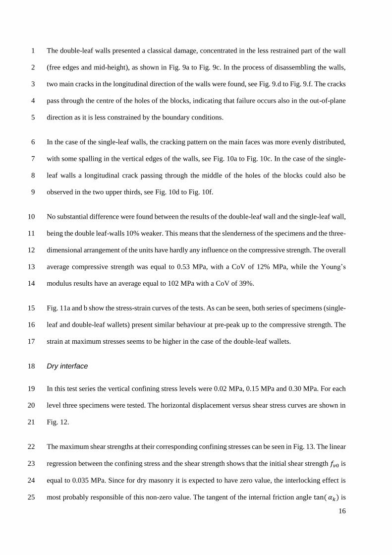
The double-leaf walls presented a classical damage, concentrated in the less restrained part of the wall 1
(free edges and mid-height), as shown in Fig. 9a to Fig. 9c. In the process of disassembling the walls, 2
two main cracks in the longitudinal direction of the walls were found, see Fig. 9.d to Fig. 9.f. The cracks 3
pass through the centre of the holes of the blocks, indicating that failure occurs also in the out-of-plane 4
direction as it is less constrained by the boundary conditions. 5
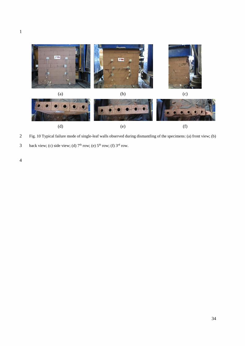
In the case of the single-leaf walls, the cracking pattern on the main faces was more evenly distributed, 6
with some spalling in the vertical edges of the walls, see Fig. 10a to Fig. 10c. In the case of the single-7
leaf walls a longitudinal crack passing through the middle of the holes of the blocks could also be 8
observed in the two upper thirds, see Fig. 10d to Fig. 10f. 9
No substantial difference were found between the results of the double-leaf wall and the single-leaf wall, 10
being the double leaf-walls 10% weaker. This means that the slenderness of the specimens and the three-11
dimensional arrangement of the units have hardly any influence on the compressive strength. The overall 12
average compressive strength was equal to 0.53 MPa, with a CoV of 12% MPa, while the Young’s 13
modulus results have an average equal to 102 MPa with a CoV of 39%. 14
Fig. 11a and b show the stress-strain curves of the tests. As can be seen, both series of specimens (single-15
leaf and double-leaf wallets) present similar behaviour at pre-peak up to the compressive strength. The 16
strain at maximum stresses seems to be higher in the case of the double-leaf wallets. 17
Dry interface 18
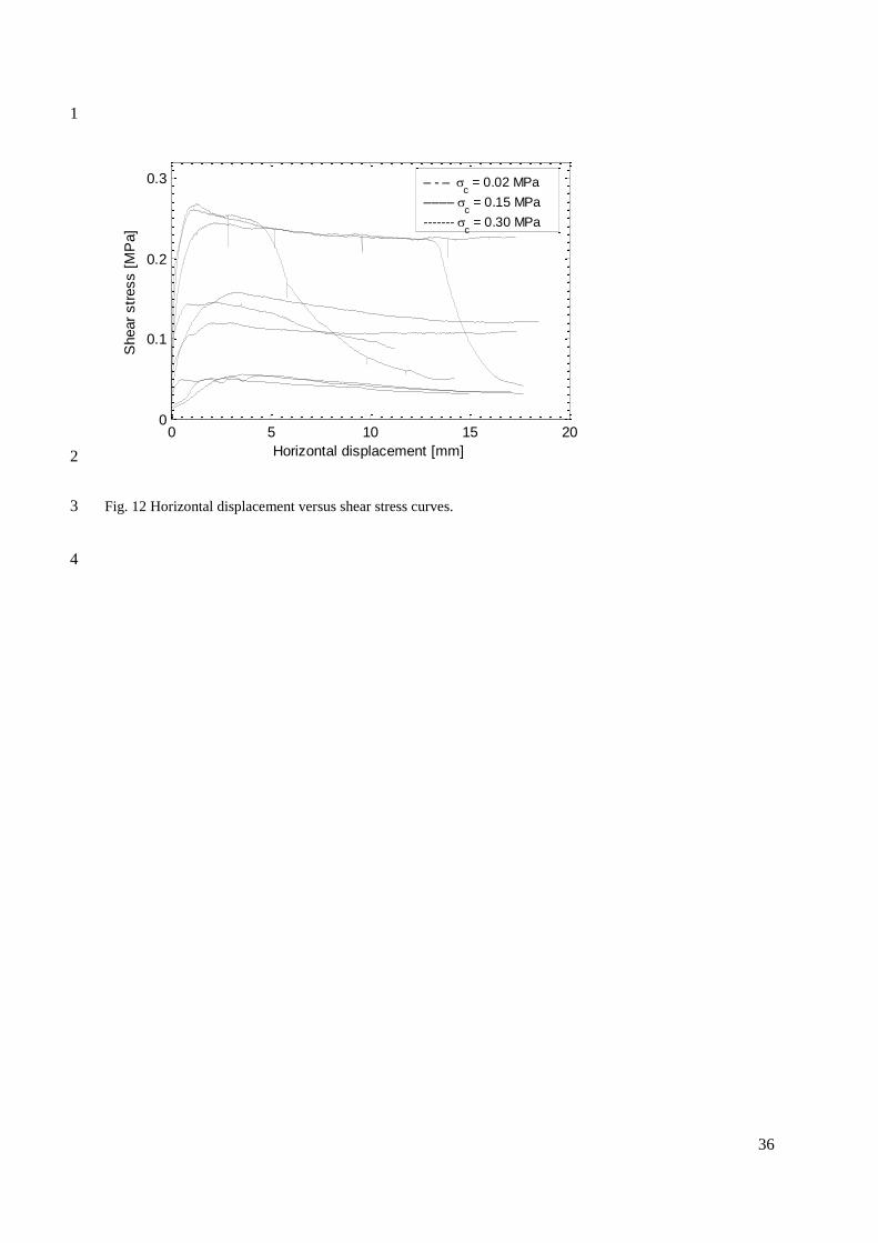
In this test series the vertical confining stress levels were 0.02 MPa, 0.15 MPa and 0.30 MPa. For each 19
level three specimens were tested. The horizontal displacement versus shear stress curves are shown in 20
Fig. 12. 21
The maximum shear strengths at their corresponding confining stresses can be seen in Fig. 13. The linear 22
regression between the confining stress and the shear strength shows that the initial shear strength 𝑓𝑣0 is 23
equal to 0.035 MPa. Since for dry masonry it is expected to have zero value, the interlocking effect is 24
most probably responsible of this non-zero value. The tangent of the internal friction angle tan( 𝛼𝑘) is 25
17
equal to 0.73, a value often encountered for masonry specimens (Lourenço and Ramos 2004). Therefore, 1
the shear strength 𝑓𝑣 of this masonry in terms of the confining stress 𝑓𝑝 can be calculated with equation 2
3 by replacing 𝑓𝑣0 and tan( 𝛼𝑘) with the obtained results. 3
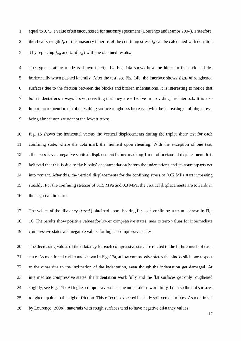
The typical failure mode is shown in Fig. 14. Fig. 14a shows how the block in the middle slides 4
horizontally when pushed laterally. After the test, see Fig. 14b, the interface shows signs of roughened 5
surfaces due to the friction between the blocks and broken indentations. It is interesting to notice that 6
both indentations always broke, revealing that they are effective in providing the interlock. It is also 7
important to mention that the resulting surface roughness increased with the increasing confining stress, 8
being almost non-existent at the lowest stress. 9
Fig. 15 shows the horizontal versus the vertical displacements during the triplet shear test for each 10
confining state, where the dots mark the moment upon shearing. With the exception of one test, 11
all curves have a negative vertical displacement before reaching 1 mm of horizontal displacement. It is 12
believed that this is due to the blocks’ accommodation before the indentations and its counterparts get 13
into contact. After this, the vertical displacements for the confining stress of 0.02 MPa start increasing 14
steadily. For the confining stresses of 0.15 MPa and 0.3 MPa, the vertical displacements are towards in 15
the negative direction. 16
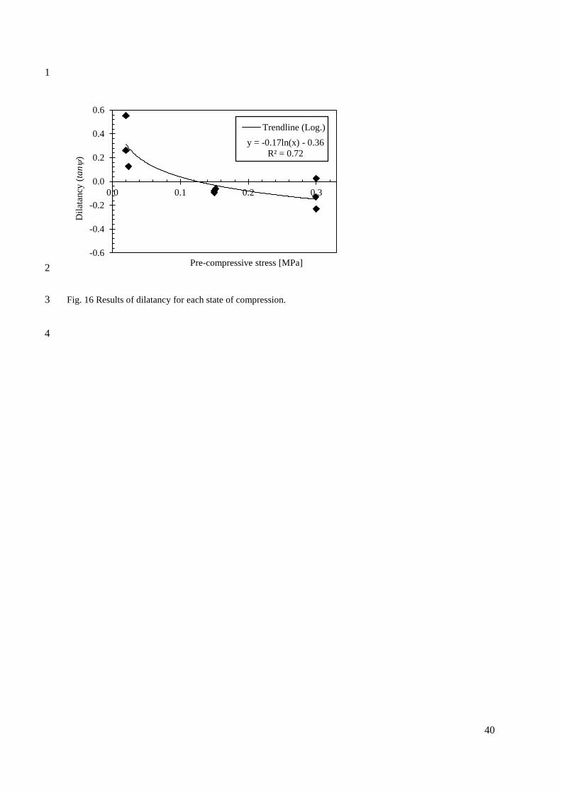
The values of the dilatancy (𝑡𝑎𝑛𝜓) obtained upon shearing for each confining state are shown in Fig. 17
16. The results show positive values for lower compressive states, near to zero values for intermediate 18
compressive states and negative values for higher compressive states. 19
The decreasing values of the dilatancy for each compressive state are related to the failure mode of each 20
state. As mentioned earlier and shown in Fig. 17a, at low compressive states the blocks slide one respect 21
to the other due to the inclination of the indentation, even though the indentation get damaged. At 22
intermediate compressive states, the indentation work fully and the flat surfaces get only roughened 23
slightly, see Fig. 17b. At higher compressive states, the indentations work fully, but also the flat surfaces 24
roughen up due to the higher friction. This effect is expected in sandy soil-cement mixes. As mentioned 25
by Lourenço (2008), materials with rough surfaces tend to have negative dilatancy values. 26
18
Discussion 1
A summary of the main experimental results is given in Table 2. In general, the attained compressive 2
strengths results of the ICEBs are similar to those obtained to other authors for sandy soils (Reddy and 3
Gupta, 2005). These sandy soils do not attain the higher strengths which clayey soil attain, but their 4
strength is sufficient for construction according to the different earth construction guidelines (ASTM 5
D1633-00 2007; ARS674 1996; DL 2009; CSIRO 1987; NMAC 2006; AEI 2005; HB195 2002). The 6
soil which was selected in Malawi was common available soil on a construction site, showing that using 7
this soil is possible for CEB manufacturing. 8
The CoV of the blocks is 24%. Other authors such as Morel et al. (2007) reports a CoV of 26% and 9
Piattoni et al. (2011) between 11% and 19%. Most authors mentioned throughout this paper do not report 10
the scatter of their results, and a comparison cannot be made. The large variability of mechanical 11
properties is well known to the earth building community and seems to be intrinsic to the system. The 12
compressive strength of the masonry corresponds to 48% of the strength of the small cylinders, to 23% 13
of the strength of the blocks and to 61% of the strength of the masonry prisms. The NZS4297 (1998) 14
standard defines the compressive strength of CEB masonry (𝑓𝑚) as half of the unconfined compressive 15
strength (i.e. the compressive strength of the prisms (𝑓𝑚𝑝), which is close to the 61% obtained in this 16
test campaign. The NZS4297 (1998) standard also defines that the strength of the masonry as 3.5 times 17
the flexural strength. In this case, the value is closer to 2.5 times the flexural strength. The lower strength 18
of double-leaf of around 10% can be due to the variability of the material and some geometrical 19
imperfection defects on the interlocking blocks between the two leaves, as the slenderness is not 20
expected to play a role in the response of the adopted specimens. 21
Concerning the tensile strength, the values obtained indirectly by the flexural test on blocks are around 22
5% and 9% of the compressive strength of the cylinders and blocks, respectively. 23
The measured average Young’s moduli of the compressive tests vary between 102 MPa and 163 MPa. 24
The HB195 (2002) standard proposes a Young’s modulus E of 200 MPa for CEB masonry and the 25

19
NZS4297 (1998) defines the Young’s modulus of the masonry as 300 multiplied by the compressive 1
strength of the masonry. Using the obtained compression strength and the definition of the NZS4297 2
(1998) to calculate E, the result is of 159 MPa. Therefore, the Young’s modulus of the tested ICEB 3
masonry seems to be a little bit lower but within the range of the ones proposed by these earth 4
construction standards. 5
The shear strength of the masonry joints depends of the confining stress and the initial shear strength, 6
which in this case seems to be provided by the interlocking. Since this is just the shear strength of the 7
interface between the horizontal blocks, shear tests of masonry specimens have to be carried out to 8
determine the shear strength of the assemblage. 9
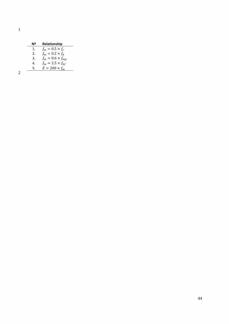
Finally, taking into account the previous statements and using the values of Table 2, approximate relationships 10
based on the smaller tests can be established for the studied ICEB masonry. 11
Table 3 shows the ones that could be the most useful. 12
Conclusions 13
On this work, experimental tests were carried out to characterize dry-stack interlocking stabilized 14
compressed earth blocks. Different tests have been made to characterize the mechanical properties of 15
the soil-cement mix, the strength of interlocking compressive earth blocks (ICEB) and the compressive 16
strength of dry-stack masonry wallets. Based on these test results, different average strength values and 17
the relationships between them were proposed. 18
Even if the homogenization of the Malawian and the Portuguese block in terms of mechanical properties 19
was not successful, the test campaign was continued because the results of this study are valuable and 20
give an insight into dry-stack ICEB masonry. They can be regarded as conservative results, since the 21
Portuguese blocks used represent well the average of the minimum strength given by the various codes 22
and guidelines. 23

20
The results of the masonry wallets can be considered as representative of real dry-stack ICEB masonry 1
walls. The strength and Young’s modulus of the ICEB masonry can be determined indirectly through 2
the compressive strength of the small cylinders, blocks or prisms or through the flexural strength of the 3
blocks. 4
The interlocking of the blocks proved to be effective. During the shear tests at low compressive states 5
both of the indentation always broke. Although they provide low initial shear strength, the interlocking 6
plays a fundamental role when ICEB masonry is loaded in the in plane or out-of-plane direction, 7
as shown by Uzoegbo and Ngowi (2004) and Bland et al. (2011). 8
ACKNOWLEDGEMENT 9
This work was carried out under the research project HiLoTec - Development of a Sustainable Self-Construction 10
System for Developing Countries. The authors wish to thank Mota-Engil Constructing Group for supporting this 11
project. 12
REFERENCES 13
AEI (2005) Earthquake resistant buildings with hollow interlocking blocks. Auroville Earth Institute, UNESCO 14
Chair - Earthern Architecture, Auroville. 15
Appro (2014) APPRO TECHNO. Manual Press Terstaram product specifications. 16
http://www.approtechno.com/Manuel-press-Terstaram. Accessed 14 April 2014. 17
ARS674 (1996) Compressed Earth Blocks - Technical Specifications for Ordinary Compressed Earth Blocks. 18
African Regional Standards for compressed earth blocks, CDI Guides ‘Technologies Series’ No. 11. 19
ASTM C1314-03b (2003) Standard Test Method for Compressive Strength of Masonry Prisms. American Society 20
for Testing and Materials International, Philadelphia. 21
ASTM D1633-00 (2007) Standard Test Methods for Compressive Strength of Molded Soil-Cement Cylinders. 22
American Society for Testing and Materials International, Philadelphia. 23
21
Bland DW, Jansen DC, Stirling BJ, Qu B, Laursen PT (2011) In-plane cyclic performance of interlocking 1
compressed earth block shear walls. Proceedings of the 11th North American Masonry Conference, June 5-8, 6.01-2
2, Minneapolis. 3
Browne G (2009) Stabilized interlocking rammed earth blocks: Alternatives to cement stabilization. Proceedings 4
of the 11th International Conference on Non-conventional Materials and Technologies (NOCMAT 2009), 6-9 5
September 2009, Bath, UK. 6
Bui Q, Morel JC (2009) Assessing the anisotropy of rammed earth. Proceedings of the 11th International 7
Conference on Non-conventional Materials and Technologies (NOCMAT 2009), 6-9 September 2009, Bath, UK. 8
CSIRO (1987) Earth Wall Construction. Bulletin 5, Commonwealth Scientific and Industrial Research 9
Organization of Building Construction and Engineering, Australia. 10
DL (2009) Lehmbau Regeln: Begriffe - Baustoffe - Bauteile (Adobe construction: Concept - Building material - 11
Components). Dachverband Lehm, Vieweg Teubner Verlag, 3rd edition. 12
Elvin A, Uzoegbo HC (2011) Response of a full-scale dry-stack masonry structure subject to experimentally 13
applied earthquake loading. J. South Afr. Inst. Civ. Eng. 53(1):22–32 14
EN 772-1 (2000) Methods of test for masonry units - Part 1: Determination of compressive strength. European 15
Standards. 16
EN 772-6 (2001) Methods of test for masonry units - Part 6: Determination of bending tensile strength of aggregate 17
concrete masonry units. European Standards. 18
EN 1052-1 (1999) Methods of test for masonry - Part 1: Determination of compressive strength. European 19
Standards. 20
EN 1052-3 (2002) Methods of test for masonry - Part 3: Determination of initial shear strength. European 21
Standards. 22
EN 1052-4 (2000) Methods of test for masonry - Part 4: Determination of shear strength including damp proof 23
course. European Standards. 24

22
EN 13286-42 (2003) Unbound and hydraulically bound mixtures - Part 42: Test method for determination of the 1
indirect tensile strength of hydraulically bound mixtures. European Standards. 2
Galán-Marín C, Rivera-Gómez C, Petric J (2010) Clay-based composite stabilized with natural polymer and fibre. 3
Constr. Build. Mater. 24:1462–1468 4
Gate (2005) Interlocking Compressed Earth Blocks: Volume II. Manual of Construction. Center for Vocational 5
Building Technology, German Appropriate Technology Exchange – GATE, Eshborn. 6
HB195 (2002) The Australian Earth Building Handbook. Standards Australia International, Sydney. 7
Heath A, Walker P, Fourie C, Lawrence M (2009) Compressive strength of extruded unfired clay masonry units. 8
Proceedings of the Institute of Civil Engineers: Construction Materials, 162 (3), pp. 105-112 9
Jayasinghe C, Kamaladasa N (2007) Compressive strength characteristics of cement stabilized rammed earth 10
walls. Constr. Build. Mater. 21(11):1971-1976 11
Kuchena JC, Usiri P (2009) Low cost construction technologies and materials - Case study Mozambique. 12
Proceedings of the 11th International Conference on Non-conventional Materials and Technologies (NOCMAT 13
2009), 6-9 September 2009, Bath, UK. 14
Lenci S, Clementi F, Sadowski T (2012) Experimental determination of the fracture properties of unfired dry earth. 15
Eng. Fract. Mech. 87:62-72 16
Lourenço PB, Ramos LF (2004): Characterization of the Cyclic Behavior of Dry Masonry Joints, ASCE – Struct. 17
Eng. Vol. 130(5), pp. 779-786 18
Lourenço PB (2008) Structural masonry analysis: Recent developments and prospects. 14th International Brick 19
and Block Masonry Conference, 17-20 February, Sydney, Australia. 20
Lyamuya PK, Arch KN (2013) Earth Construction in Botswana: Reviving and Improving the Tradition. CAA 21
DHAKA 2013, 20th General Assembly and Conference, February 19–24, Dhaka. 22
Minke G (2006) Building with earth: design and technology of a sustainable architecture. Birkhäuser, Basel. 23

23
Morel JC, Pkla A (2002) A model to measure compressive strength of compressed earth blocks with the ‘3 points 1
bending test’. Constr. Build. Mater. 16:303–310 2
Morel JC, Pkla A, Walker P (2007) Compressive strength testing of compressed earth blocks. Constr. Build. Mater. 3
21:303-309 4
NMAC (2006) New Mexico Administrative Code (NMAC). Title 14, Chapter 7, Part 4: New Mexico Earthen 5
Building Materials Code. 6
NZS4297 (1998) Engineering Design of Earth Buildings. Standards New Zealand, Wellington, New Zealand. 7
NZS4299 (1998) Earth Buildings Not Requiring Specific Design. Standards New Zealand, Wellington, New 8
Zealand. 9
Piattoni Q, Quagliarini E, Lenci S (2011) Experimental analysis and modelling of the mechanical behaviour of 10
earthen bricks. Constr. Build. Mater. 25:2067–2075 11
Pluijm RVD (1999) Out of plane bending of masonry behaviour. PhD Thesis. Eindhoven University of 12
Technology, The Netherlands. 13
Reddy BVV, Gupta A. (2005) Characteristics of soil-cement blocks using highly sandy soils. Mater. Struct. 14
38:651–658 15
UN HABITAT (2009) Interlocking Stabilised Soil Blocks: Appropriate earth technologies in Uganda. United 16
Nations Human Settlements Programme, Nairobi. 17
USAID (2004) Country profile property rights and resource governance, Malawi. USAID land tenure and property 18
rights portal. http://usaidlandtenure.net. Accessed 21 May 2014. 19
Uzoegbo H (2001) Lateral loading test on dry-stack interlocking block walls. Proceeding International Conference 20
on structural Engineering, Cape Town, Vol I. 21
Uzoegbo HC, Ngowi JV (2003) Structural Behaviour of Dry-Stack Interlocking Block Walling Systems Subject 22
to In-Plane Loading. Concr. Beton 103:9–13 23
Uzoegbo HC, Ngowi JV (2004) Lateral Strength of a Dry-Stack wall System. Mason. Int. 17(3):122–128 24
24
Yetgin Ş, Çavdar Ö, Çavdar A (2008) The effects of the fiber contents on the mechanic properties of the adobes. 1
Constr. Build. Mater. 22 (3):222-227 2
Zingano B (2005) The problem of fuel wood energy demand in Malawi with reference to the construction industry. 3
Zingano and Associates, Lilongwe. http://www.joyhecht.net/mulanje/refs/Zingano-fuelwood-bricks-2005.pdf. 4
Accessed 21 May 2014. 5
6

25
List of Figures 1
Fig. 1 ICEB: (a) Block and dimensions (in mm); (b) single-leaf wall; (c) double-leaf wall. 2
Fig. 2 Compressive strength of cylinder samples: (a) evolution of compressive strength with maxima 3
and minima; (b) stress-strain curves of the samples tested at an age of 28 days. 4
Fig. 3 Stress-displacement curve of the indirect tensile tests. 5
Fig. 4 Compression strength of the CEB with maxima and minima. 6
Fig. 5 Stress-strain curves of blocks: (a) Malawian soil, 28 days; (b) Portuguese soil, 56 days. 7
Fig. 6 Correlation between the Young's modulus and the compressive strength of the blocks. 8
Fig. 7 Stress-strain curves of prisms in compression. 9
Fig. 8 Failure pattern of the masonry prisms (cracks are highlighted in red): (a) spalling of the main face; 10
(c) failure at the tip; (c) broken corner; (d) interrupted cracks. 11
Fig. 9 Typical failure mode of double-leaf walls observed during dismantling of the specimens: (a) front 12
view; (b) back view; (c) side view; (d) 7th row; (e) 5th row; (f) 3rd row. 13
Fig. 10 Typical failure mode of single-leaf walls observed during dismantling of the specimens: (a) front 14
view; (b) back view; (c) side view; (d) 7th row; (e) 5th row; (f) 3rd row. 15
Fig. 11 Stress-strain curves of the wallets: (a) single-leaf; (b) double-leaf. 16
Fig. 12 Horizontal displacement versus shear stress curves. 17
Fig. 13 Results of the triplet tests. 18
Fig. 14 Failure mode: (a) the CEB in the middle slides horizontally; (b) the CEB show broken 19
indentation and roughened surfaces. 20
Fig. 15 Shear displacement versus the vertical displacement during the triplet test. 21
Fig. 16 Results of dilatancy for each state of compression. 22
Fig. 17 Failure mode for different compressive states: (a) 0.02 MPa; (b) 0.15 MPa; 0.30 MPa. 23
24
List of Figures 25
Table 1 Summary of the laboratory tests carried out. 26
Table 2 Summary of the test results. 27
Table 3 Relationships between the characteristic values. 28
29

26
1
2
Fig. 1 ICEB: (a) Block and dimensions (in mm); (b) single-leaf wall; (c) double-leaf wall. 3
4
(a) (b) (c)
27
1
(a)
(b)
Fig. 2 Compressive strength of cylinder samples: (a) evolution of compressive strength with maxima and minima; 2
(b) stress-strain curves of the samples tested at an age of 28 days. 3
4
Fig. 3 Stress-displacement curve of the indirect tensile tests. 5
6
0.0
0.5
1.0
1.5
2.0
2.5
0 10 20 30
Co
mp
ressiv
e s
tre
ng
th [M
Pa
]
Age [days]
Average
0 0.02 0.04 0.06 0.080
0.5
1
1.5
2
2.5
Strain
Str
ess
[MP
a]
0 0.25 0.5 0.75 1 1.25 1.50
0.02
0.04
0.06
0.08
Vertical displacement [mm]
Ten
sile
str
ess
(indir
ect)
[M
Pa]
28
1
2
Fig. 4 Compression strength of the CEB with maxima and minima. 3
4
0.0
1.0
2.0
3.0
4.0
0 10 20 30 40 50 60
Co
mp
ress
ive
stre
ngth
[M
Pa]
Age [days]
Malawi
Portugal

29
1
(a)
(b)
Fig. 5 Stress-strain curves of blocks: (a) Malawian soil, 28 days; (b) Portuguese soil, 56 days. 2
3
0 0.04 0.08 0.12 0.160
1
2
3
4
Strain
Com
pre
ssiv
e st
ress
[M
Pa]
0 0.04 0.08 0.12 0.160
1
2
3
4
Strain
Com
pre
ssiv
e st
ress
[M
Pa]

30
1
2
Fig. 6 Correlation between the Young's modulus and the compressive strength of the blocks. 3
4
R² = 0.72R² = 0.88
0.0
1.0
2.0
3.0
4.0
0 100 200 300
Co
mp
ress
ive
stre
ngth
[M
Pa]
Young's modulus[MPa]
Malawi, 28 days
Portugal, 56 days

31
1
2
Fig. 7 Stress-strain curves of prisms in compression. 3
4
0 0.005 0.01 0.015 0.02 0.0250
0.3
0.6
0.9
1.2
Strain
Str
ess
[MP
a]

32
1
(a)
(b)
(c)
(d)
Fig. 8 Failure pattern of the masonry prisms (cracks are highlighted in red): (a) spalling of the main face; (c) failure 2
at the tip; (c) broken corner; (d) interrupted cracks. 3
4

33
1
(a)
(b)
(c)
(d)
(e)
(f)
Fig. 9 Typical failure mode of double-leaf walls observed during dismantling of the specimens: (a) front view; (b) 2
back view; (c) side view; (d) 7th row; (e) 5th row; (f) 3rd row. 3
4
34
1
(a)
(b)
(c)
(d)
(e)
(f)
Fig. 10 Typical failure mode of single-leaf walls observed during dismantling of the specimens: (a) front view; (b) 2
back view; (c) side view; (d) 7th row; (e) 5th row; (f) 3rd row. 3
4

35
1
(a)
(b)
Fig. 11 Stress-strain curves of the wallets: (a) single-leaf; (b) double-leaf. 2
3
0 0.005 0.01 0.015 0.020
0.2
0.4
0.6
0.8
StrainS
tress [
MP
a]
0 0.005 0.01 0.015 0.020
0.2
0.4
0.6
0.8
Strain
Str
ess [
MP
a]
0 0.005 0.01 0.015 0.020
0.2
0.4
0.6
0.8
StrainS
tress [
MP
a]
0 0.005 0.01 0.015 0.020
0.2
0.4
0.6
0.8
Strain
Str
ess [
MP
a]
36
1
2
Fig. 12 Horizontal displacement versus shear stress curves. 3
4
0 5 10 15 200
0.1
0.2
0.3
Horizontal displacement [mm]
Shear
str
ess [
MP
a]
– - – c = 0.02 MPa
–––– c = 0.15 MPa
------- c = 0.30 MPa

37
1
2
Fig. 13 Results of the triplet tests. 3
4
y = 0.733x + 0.035
R² = 0.983
0.00
0.10
0.20
0.30
0.0 0.1 0.2 0.3 0.4
Shea
r st
rength
[M
Pa]
Confining stress [MPa]
Experimental
results
Lin. Reg.

38
1
(a)
(b)
Fig. 14 Failure mode: (a) the CEB in the middle slides horizontally; (b) the CEB show broken indentation and 2
roughened surfaces. 3
4

39
1
2
Fig. 15 Shear displacement versus the vertical displacement during the triplet test. 3
4
0 5 10 15 20 25-2
-1
0
1
2
Horizontal displacement [mm]
Vert
ical dis
pla
cem
ent
[mm
]
0 1 2-0.5
0
0.5
– - – c = 0.02 MPa
–––– c = 0.15 MPa
------- c = 0.30 MPa
40
1
2
Fig. 16 Results of dilatancy for each state of compression. 3
4
y = -0.17ln(x) - 0.36
R² = 0.72
-0.6
-0.4
-0.2
0.0
0.2
0.4
0.6
0.0 0.1 0.2 0.3
Dil
atan
cy (
tan
)
Pre-compressive stress [MPa]
Trendline (Log.)

41
1
v
h
v
h
v
h
h 2
Fig. 17 Failure mode for different compressive states: (a) 0.02 MPa; (b) 0.15 MPa; 0.30 MPa. 3
4
(a) (b) (c)

42
1
Table 1 Summary of the laboratory tests carried out. 2
Specimen type Tests
Small cylinders (soil) -Compression -Indirect tension
Units -Compression -Flexure
Prisms & masonry wallets -Compression
Interface between ICEB -Initial shear
3
4

43
1
Table 2 Summary of the test results. 2
Specimen type Measured strength Symbol
Strength Young’s modulus
Average [MPa]
COV [%]
Average [MPa]
COV [%]
Small cylinders compressive 𝑓𝑐 1.10 34 106 32
Small cylinders indirect tensile 𝑓𝑖𝑡 0.06 24 n/a n/a Single blocks compressive 𝑓𝑏 2.34 24 163 30
Single blocks flexural 𝑓𝑏𝑓 0.21 19 n/a n/a
Masonry prism compressive 𝑓𝑚𝑝 0.87 24 129 19
Masonry wallets compressive 𝑓𝑚 0.53 12 102 39
Prism (triplet) shear 𝑓𝑣 0.73𝑓𝑝 +
0.035 n/a n/a n/a
n/a= does not apply
3
Table 3 Relationships between the characteristic values. 4
5
44
1
Nº Relationship
1. 𝑓𝑚 = 0.5 × 𝑓𝑐 2. 𝑓𝑚 = 0.2 × 𝑓𝑏
3. 𝑓𝑚 = 0.6 × 𝑓𝑚𝑝
4. 𝑓𝑚 = 2.5 × 𝑓𝑏𝑓
5. 𝐸 = 200 × 𝑓𝑚 2