Embed Size (px)
Citation preview
The Visual Computer manuscript No.(will be inserted by the editor)
Bing-Yu Chen · Yutaka Ono · Tomoyuki Nishita
Character Animation Creation using Hand-drawn Sketches
Abstract To create a character animation, a 3D char-acter model is often needed. However, since the human-like character is not a rigid-body, to deform the char-acter model to fit each animation frame is a tediouswork. Therefore, we propose an easy-to-use method forcreating a set of consistent 3D character models fromsome hand-drawn sketches while keeping the projectedsilhouettes and features of the created models consistentwith the input sketches. Since the character models pos-sess vertex-wise correspondences, they can be used forframe-consistent texture mapping or for making charac-ter animations. In our system, the user only needs toannotates the correspondence of the features among theinput vector-based sketches; the rest processes are allperformed automatically.
Keywords Cel Animation · Non-Photorealistic Render-ing · 3D Morphing · Consistent Mesh Parameterization ·Sketches
1 Introduction
The techniques of computer graphics are widely used forsupporting the creation process of animations. In the tra-ditional approach, animators had to draw each frame ofan animation by hand on paper or cel. This has now beensuperseded by a method in which the frames are drawnusing computer-assisted tools, or by rendering the scenesusing 3D models. Moreover, if the animators use vector-based drawings rather than raster-based paintings, they
Bing-Yu ChenNational Taiwan UniversityE-mail: [email protected]
Yutaka OnoThe University of TokyoE-mail: [email protected]
Tomoyuki NishitaThe University of TokyoE-mail: [email protected]
can scale the drawings to any size and the images thus re-quire less storage space. Meanwhile, by using 3D models,the animators can add many attractive effects to theiranimations, e.g., shading, shadowing or texture mapping,which are difficult or time-consuming to draw by hand.
However, it is still difficult to construct human-likecharacter models to support the animation making process,since their shapes are often drawn with considerable dis-tortions due to the characters’ motion, changing view-points or animators’ exaggerations. Although it might bepossible to make several 3D models whose shapes changewith such distortions, deforming the models manually foreach frame is a very time-consuming task. Therefore, wepropose a method for creating a set of 3D polygon modelsthat correspond to the input frames of some hand-drawnsketches. Animators can use the set of models for easilyadding 3D effects, especially for adding shading effectsor shadows to the animation and for mapping textures toa character, while preserving the user-specified featureswith frame-to-frame coherence.
Our method takes a single cut of an animation from asequence of vector-based images drawn by animators asthe input, where each of the images contains the shapeand features of a character in a certain (key) frame ofthe animation. The correspondences of the features be-tween the frames are specified by the user. Our systemthen creates a consistent 2D base domain according tothe features and the silhouettes of the character on eachframe. By subdividing the base domain recursively, thesystem generates a set of consistent 2D triangle meshesthat approximate the features and the silhouettes of thecharacter on each frame. After an inflation process, a setof consistent 3D polygon models is created, so that theprojected silhouettes and features of the models are con-sistent with the input frames. In the all processes, onlythe feature specification is operated by the user, the restsare automatically done by our system.
The created 3D models have the following properties:(1) Silhouette preservation: the projected silhouetteof each created model coincides with that of the char-acter on the corresponding original frame. (2) Frame-
2 Bing-Yu Chen et al.
to-frame correspondences: the created models ex-hibit vertex-wise correspondences. (3) Feature preser-
vation: all of the features of the input image are em-bedded in the corresponding model and the projectionof these features coincides on the original frame.
The silhouette preservation property allows the an-imators to use the set of consistent models that havebeen created for adding shading effects or shadows, andthe frame-to-frame correspondence property allows themto use frame-consistent texture mapping. Texture map-ping with user-specified constraints along the input vec-tors between the input image and the model, as wellas of models, is possible due to the feature preserva-
tion property. Moreover, since the created models pos-sess vertex-wise correspondences, the method can assistthe animators to generate in-between shapes among theinput frames by applying morphing techniques.
2 Related Work
To add attractive and impressive 3D effects onto cel ani-mations, the animators usually require 3D geometric in-formation. The method of obtaining 3D information forrigid objects is quite straightforward, since they can sim-ply call on modelers to construct 3D models. Those 3Dmodels can be directly rendered by using so-called toonor comic shaders [22], together with several stylized ren-dering methods [7] [8] [15]. However, for human-like char-acters, there seems to be no simple solution to obtaining3D information due to their artistic distortions.
Rademacher [18] presented a typical method to createan animation using a 3D character model, generated bya professional animator. In this method, the animator-generated 3D character model is deformed to match sev-eral reference images, and the deformed models are theninterpolated to create a 3D geometry whose shape de-forms with the changes of viewpoint. Martın et al. [13]also presented a related method. Since the animatorsmanually define the 3D models at each key viewpoint,these methods were able to satisfy the three propertiesthat are highlighted in our method, i.e., silhouette preser-
vation, feature preservation, and frame-to-frame corre-
spondences, and they could be used for many applica-tions. However, manually editing the 3D models is still atime-consuming task. Li et al. [12] also provide a sketch-based method to generate character animation.
A texture mapping method for cel animation pre-sented by Correa et al. [3] also uses 3D models cre-ated by animators. Although a reference model must becreated manually, a simple interface for deforming themodel to meet the silhouette preservation and frame-to-
frame correspondence criteria are provided. Therefore,this technique may also be used for adding shading ef-fects or shadows. However, since the feature preservation
requirement is only an approximation, it cannot be used
for complex textures that must critically satisfy the user-specified constraints.
In order to create a 3D model, Igarashi et al. [6]and Karpenko et al. [10] proposed easy-to-use sketch-ing systems with which the user draws only the silhou-ette. The systems can then create a 3D model that sat-isfies the silhouette preservation requirement for a sin-gle frame. However, it is not simple to extend this toanimation, since the frame-to-frame correspondence cri-terion is obviously not considered. A method proposedby Petrovic et al. [17] for adding shadows cast by thecharacters on the scenes requires only a small effort onthe part of the animators, because it creates 3D mod-els semi-automatically using the above methods. How-ever, these models do not possess feature preservation orframe-to-frame correspondence properties, so the rangeof applications where these models can be used is verylimited.
Some computer vision techniques could be used toconstruct 3D models from 2D tracking-points. However,most of these techniques assume that the object is rigid,and hence they are not applicable to the characters incharacter animations. Several methods, e.g., those pre-sented by Bregler et al. [2] and by Torresani et al. [21]have been proposed for generating 3D non-rigid models,but they all require a large number of images and track-ing points. Therefore, these methods cannot be appliedfor key-frame character animations in general. Our pre-vious work [16] also used some computer vision methodsto construct a set of consistent 3D character models froman existing cel animation for adding some effects into theoriginal animation. Hence, the methods presented in thispaper are different from the previous one, since the in-formation on some hand-drawn sketches is not so muchas that on a cel animation which has more frames thanthe input sketches.
In this paper we aim to identify a method that canbe used to create consistent 3D models featuring sil-
houette preservation, feature preservation and frame-to-frame correspondence properties. Applications for thesemodels include adding shading effects and shadows andmapping textures within the animators’ constraints. Theburden for the animators with this technique is not sodifferent from the method provided by Petrovic et al.
[17].
3 System Overview
In this section, the system overview is described from ananimator’s viewpoint. Initially, he or she loads a sequenceof images, which are hand-drawn sketches, representingsome key frames of a character animation shown in Fig. 1(a)∼(c). The animator then overwrites some stroke vec-tors on the features of the images as shown in Fig. 1(d)∼(f). This work can be done by using some com-mercial tools which can convert raster-based or scanned

Character Animation Creation using Hand-drawn Sketches 3
hand-drawn sketches into vector-based images. Of course,if the original input images are already vector-based likethe example shown in Fig. 5 (a), this step can be omit-ted. After specifying the corresponding points and pathsbetween the frames by adding some ID numbers, the pre-processing setup step has been completed. The animatorcan then obtain a set of consistent 3D models automati-cally, as shown in Fig. 1 (g)∼(i). These models can thenbe used for further applications, such as texture mappingand shadowing, as shown in Fig. 1 (j)∼(l).
(a) (b) (c)
(d) (e) (f)
(g) (h) (i)
(j) (k) (l)
Fig. 1 User input hand-drawn sketches of a dancing bearand corresponding output models. (a)∼(c) Three of the sixinput sketches. (d)∼(f) Converted stroke vectors from inputsketches with user-specified correspondences. (g)∼(i) Output3D models shown in wireframe. (j)∼(l) Texture-mapped mod-els with shadows using toon rendering.
With some complex characters, some areas of thecharacter are hidden by others, for example, the forearmsand the upper arms of the dancing bear shown in Fig. 1.In this case, the animator has to draw some stroke vec-tors and specify the correspondence of the missing partsby separating the input images into multiple layers. Thisdecomposition is natural for the process of making celanimations [4].
4 Generation of Consistent 2D Meshes
After the pre-processing setup described in Section 3,we now have F vector-based images as Fig. 1 (d)∼(f),where F is the number of input frames. These imagesare treated as F sets of 2D (x-y) planar graphs, and eachgraph is denoted as Gf = (Wf , Pf ), f = [1, F ], where Wf
is a set of points in <2 and Pf is a set of finite simplepaths in <2 connecting two different points in Wf , andeach path is sampled to a polyline. Moreover, we assumethat the graphs are consistent which can be guaranteedby guiding the user’s input, where two graphs are con-sistent means that there are one-to-one correspondencesamong their points and paths as the two graphs shownin Fig. 2 (a).
To generate 2D meshes from the graphs, it is neces-sary to convert the graphs so that they contain no iso-lated points and paths as shown in Fig. 2 (b). Therefore,we separate our consistent 2D triangle mesh generationalgorithm from a sequence of input graphs into two steps.In the first step (Section 4.1), we create a set of consistentbase domains, which are consistent triangulated graphs
G′
f (Gf ) = (Wf , P ′
f ) of Gf = (Wf , Pf ), where P ′
f ⊆ Pf ,
as shown in Fig. 2 (c) for all of the frames, which meanssome paths are inserted into the graph Gf to make eachpatch has only three points and paths, and a patch isdefined as a closed region bounded by the paths of thegraph.
In the second step (Section 4.2), we create a set ofconsistent 2D triangle meshes Mf in which the triangu-lated graphs G′
f are embedded by subdividing each patch
of G′
f , as shown in Fig. 2 (c).
4.1 Consistent Graph Triangulation
The algorithm described in this section creates a set ofconsistent base domains, which are triangulated graphsG′
f (Gf ) = (Wf , P ′
f ) from a set of consistent input graphs
Gf = (Wf , Pf ), by adding the paths, one by one, toGf . This method, which sequentially adds paths to thegraph, is modified from the method described by Kraevoy et al.
[11]. In order to describe the algorithm clearly, we useG∗
f = (Wf , P ∗
f ) as an intermediate graph between the
given set of consistent graphs Gf = (Wf , Pf ) and theoutput set of consistent base domains G′
f (Gf ) = (Wf , P ′
f )for all of the frames. We first compute a path q1 con-necting {p1,i, p1,j}, where i 6= j and p1,i, p1,j ∈ W1,which does not cross the unbounded region and whichminimizes the path length. If path q1 is found, thenwe sequentially compute paths q2, ..., qF for connecting{p2,i, p2,j}, ..., {pF,i, pF,j}, respectively, where q2, ..., qF
are corresponding paths with q1, so that the graphs G∗
1=
(W1, P∗
1∪ {q1}), ..., G
∗
F = (WF , P ∗
F ∪ {qF }) are still con-sistent.
In order to find paths q2, ..., qF , we need to search allpossible paths in the graphs from the standpoint of the
4 Bing-Yu Chen et al.
0
12
3
4
56
7
8
0
1
2
3
4
5
6
7 8
0
1
2
34
5
6
7
8
0
1
2
3
4
5
6
7
8
(a)
0
12
3
4
56
7
8
0
1
2
3
4
5
6
7 8
0
1
2
34
5
6
7
8
0
1
2
3
4
5
6
7
8
(b)
0
12
3
4
56
7
8
0
1
2
3
4
5
6
7 8
0
1
2
34
5
6
7
8
0
1
2
3
4
5
6
7
8
(c)
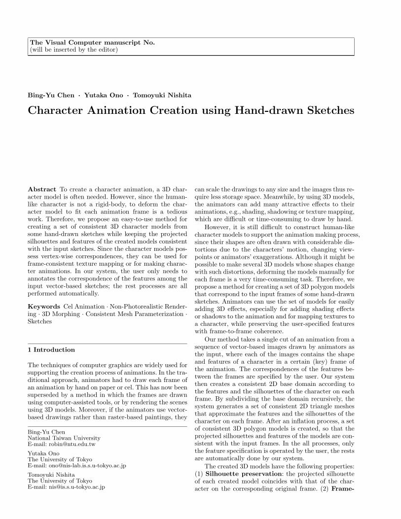
Fig. 2 (a) Input graphs of two frames. Green numbers showthe corresponding ID numbers for points and blue numbersare for paths. (b) Triangulated graphs of (a). (c) Output con-sistent 2D triangle meshes.
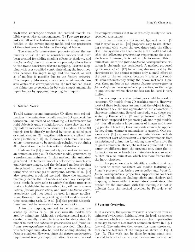
topology. To achieve this topological search and to com-pute the paths, we use trapezoidal maps of the graphs asshown in Fig. 3. The paths are generated by connectingthe centroids of the trapezoids and the centers of the ver-tical extensions, as in Fig. 3 (b) and (c). The paths arethen optimized by removal of the redundant points. Theconditions for removing the redundant points are that(1) removing the point does not change the topology ofthe path, and (2) removing the point does not move aremaining path too close to other points or paths. Thesecond condition is necessary to avoid degeneracy in thefollowing algorithms. For example, removing the squaredpoint in Fig. 3 (d) is topologically possible, but it wouldmake the path too close to other points or paths. Afterall possible paths are found, we will choose the path withthe same topology as the path in the first frame. Once thepaths q1, ..., qF are decided and added to G∗
1, ..., G∗
F , wewill check if G∗
1, ..., G∗
F have become triangulated graphto stop or continue the triangulation process.
Note that this triangulation algorithm is not symmet-ric, because graph G∗
1is dealt with first, and the others
follow on. Although it is possible to make the algorithmsymmetric by further computing path sets for G∗
2, ..., G∗
F
as the first steps and then deciding the minimum average
(a) (b)
(c) (d)
Fig. 3 Path search/computation using a trapezoidal map.(a) An input graph. (b) A trapezoidal map of (a) with its”road map”. (c) Four topologically different paths for con-necting yellow points. (d) Optimized path derived from thered path in (c).
length path sets, we have found that just dealing withG∗
1in the first instance is sufficient in our experiments.
4.2 Consistent Face Subdivision
We now have consistent base domains G′
f (Gf ) = (Wf , P ′
f ),and each patch in a base domain has a simple boundarydefined by three paths as shown in Fig. 2 (b). To cre-ate consistent 2D triangle meshes Mf , in which the in-put graphs Gf are embedded as shown in Fig. 2 (c), wefirst define 2D meshes, M∗
f = (Wf ,K∗
f ), by identifying
G′
f as meshes, where K∗
f is a simplicial complex derived
from the paths of G′
f . Since the paths of G′
f are rep-resented by polylines, M∗
f may not consist of trianglesor be consistent among frames in general. To establishconsistency over M∗
f , we apply an edge-split operator toM∗
f to make the boundary of each face have the same
number of vertices among frames as shown in Fig. 4 (b).A consistent triangulation method for simple boundarypolygons may then be applied to all the faces of the M∗
f
independently, the results of which are shown in Fig. 4(c), and we use M ′
f to denote the generated consistent2D triangle meshes. The triangulation method we usedhere is an adaptive semi-regular refinement method (acombination of 4-to-1 and 2-to-1 subdivisions).
Although M ′
f are consistent 2D triangle meshes, theymay have some undesirable creases, due to the paths thatwere added for graph triangulation, and thus may not bevalid. Therefore, we apply a smoothing method to M ′
f
based on the algorithm of Freitag et al. [5] that moveseach vertex locally to minimize an energy function, whileconstraining the positions of the vertices correspondingto Gf and get Mf .
Character Animation Creation using Hand-drawn Sketches 5
G1 G2
(a)
(b)
(c)
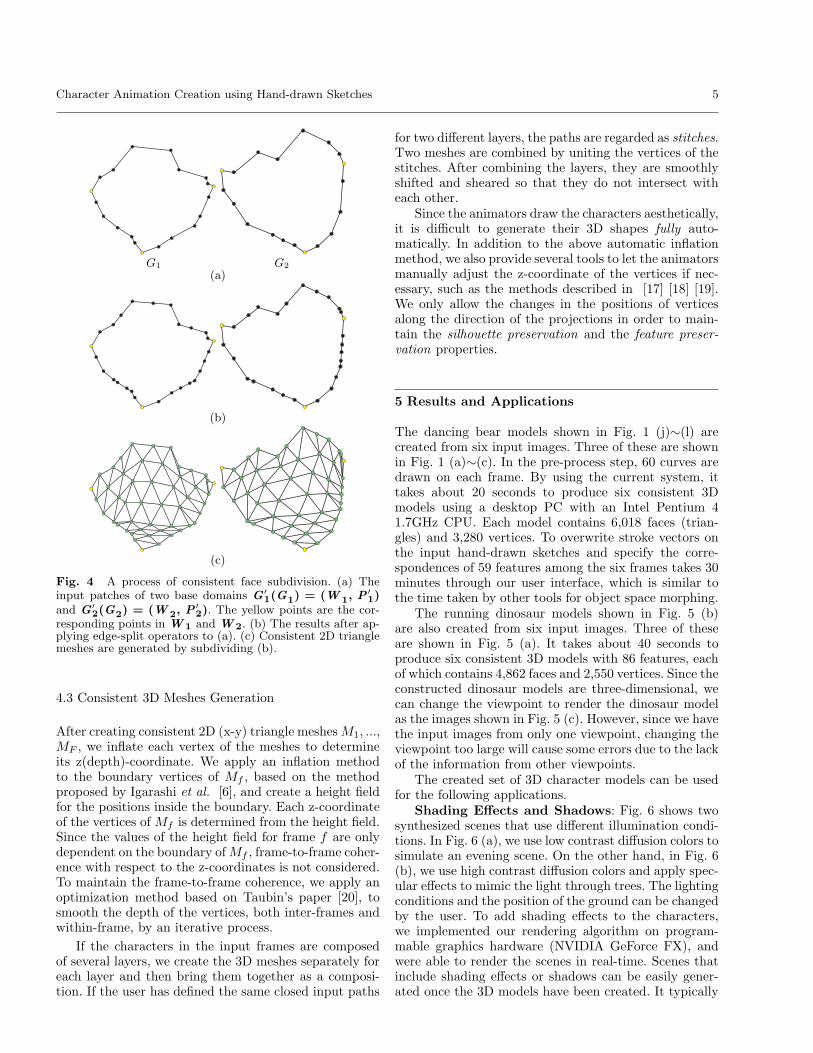
Fig. 4 A process of consistent face subdivision. (a) Theinput patches of two base domains G
′
1(G1) = (W
1, P
′
1)and G
′
2(G2) = (W
2, P
′
2). The yellow points are the cor-responding points in W 1 and W 2. (b) The results after ap-plying edge-split operators to (a). (c) Consistent 2D trianglemeshes are generated by subdividing (b).
4.3 Consistent 3D Meshes Generation
After creating consistent 2D (x-y) triangle meshes M1, ...,
MF , we inflate each vertex of the meshes to determineits z(depth)-coordinate. We apply an inflation methodto the boundary vertices of Mf , based on the methodproposed by Igarashi et al. [6], and create a height fieldfor the positions inside the boundary. Each z-coordinateof the vertices of Mf is determined from the height field.Since the values of the height field for frame f are onlydependent on the boundary of Mf , frame-to-frame coher-ence with respect to the z-coordinates is not considered.To maintain the frame-to-frame coherence, we apply anoptimization method based on Taubin’s paper [20], tosmooth the depth of the vertices, both inter-frames andwithin-frame, by an iterative process.
If the characters in the input frames are composedof several layers, we create the 3D meshes separately foreach layer and then bring them together as a composi-tion. If the user has defined the same closed input paths
for two different layers, the paths are regarded as stitches.Two meshes are combined by uniting the vertices of thestitches. After combining the layers, they are smoothlyshifted and sheared so that they do not intersect witheach other.
Since the animators draw the characters aesthetically,it is difficult to generate their 3D shapes fully auto-matically. In addition to the above automatic inflationmethod, we also provide several tools to let the animatorsmanually adjust the z-coordinate of the vertices if nec-essary, such as the methods described in [17] [18] [19].We only allow the changes in the positions of verticesalong the direction of the projections in order to main-tain the silhouette preservation and the feature preser-vation properties.
5 Results and Applications
The dancing bear models shown in Fig. 1 (j)∼(l) arecreated from six input images. Three of these are shownin Fig. 1 (a)∼(c). In the pre-process step, 60 curves aredrawn on each frame. By using the current system, ittakes about 20 seconds to produce six consistent 3Dmodels using a desktop PC with an Intel Pentium 41.7GHz CPU. Each model contains 6,018 faces (trian-gles) and 3,280 vertices. To overwrite stroke vectors onthe input hand-drawn sketches and specify the corre-spondences of 59 features among the six frames takes 30minutes through our user interface, which is similar tothe time taken by other tools for object space morphing.
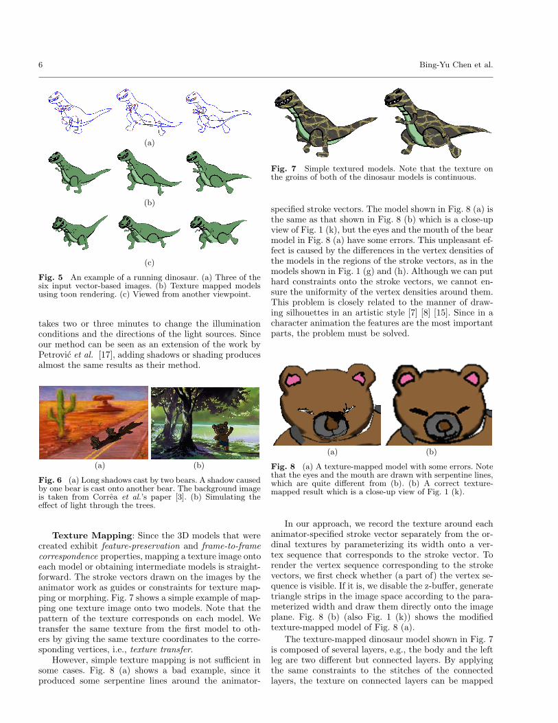
The running dinosaur models shown in Fig. 5 (b)are also created from six input images. Three of theseare shown in Fig. 5 (a). It takes about 40 seconds toproduce six consistent 3D models with 86 features, eachof which contains 4,862 faces and 2,550 vertices. Since theconstructed dinosaur models are three-dimensional, wecan change the viewpoint to render the dinosaur modelas the images shown in Fig. 5 (c). However, since we havethe input images from only one viewpoint, changing theviewpoint too large will cause some errors due to the lackof the information from other viewpoints.
The created set of 3D character models can be usedfor the following applications.
Shading Effects and Shadows: Fig. 6 shows twosynthesized scenes that use different illumination condi-tions. In Fig. 6 (a), we use low contrast diffusion colors tosimulate an evening scene. On the other hand, in Fig. 6(b), we use high contrast diffusion colors and apply spec-ular effects to mimic the light through trees. The lightingconditions and the position of the ground can be changedby the user. To add shading effects to the characters,we implemented our rendering algorithm on program-mable graphics hardware (NVIDIA GeForce FX), andwere able to render the scenes in real-time. Scenes thatinclude shading effects or shadows can be easily gener-ated once the 3D models have been created. It typically
6 Bing-Yu Chen et al.
(a)
(b)
(c)
Fig. 5 An example of a running dinosaur. (a) Three of thesix input vector-based images. (b) Texture mapped modelsusing toon rendering. (c) Viewed from another viewpoint.
takes two or three minutes to change the illuminationconditions and the directions of the light sources. Sinceour method can be seen as an extension of the work byPetrovic et al. [17], adding shadows or shading producesalmost the same results as their method.
(a) (b)
Fig. 6 (a) Long shadows cast by two bears. A shadow causedby one bear is cast onto another bear. The background imageis taken from Correa et al.’s paper [3]. (b) Simulating theeffect of light through the trees.
Texture Mapping: Since the 3D models that werecreated exhibit feature-preservation and frame-to-frame
correspondence properties, mapping a texture image ontoeach model or obtaining intermediate models is straight-forward. The stroke vectors drawn on the images by theanimator work as guides or constraints for texture map-ping or morphing. Fig. 7 shows a simple example of map-ping one texture image onto two models. Note that thepattern of the texture corresponds on each model. Wetransfer the same texture from the first model to oth-ers by giving the same texture coordinates to the corre-sponding vertices, i.e., texture transfer.
However, simple texture mapping is not sufficient insome cases. Fig. 8 (a) shows a bad example, since itproduced some serpentine lines around the animator-
Fig. 7 Simple textured models. Note that the texture onthe groins of both of the dinosaur models is continuous.
specified stroke vectors. The model shown in Fig. 8 (a) isthe same as that shown in Fig. 8 (b) which is a close-upview of Fig. 1 (k), but the eyes and the mouth of the bearmodel in Fig. 8 (a) have some errors. This unpleasant ef-fect is caused by the differences in the vertex densities ofthe models in the regions of the stroke vectors, as in themodels shown in Fig. 1 (g) and (h). Although we can puthard constraints onto the stroke vectors, we cannot en-sure the uniformity of the vertex densities around them.This problem is closely related to the manner of draw-ing silhouettes in an artistic style [7] [8] [15]. Since in acharacter animation the features are the most importantparts, the problem must be solved.
(a) (b)
Fig. 8 (a) A texture-mapped model with some errors. Notethat the eyes and the mouth are drawn with serpentine lines,which are quite different from (b). (b) A correct texture-mapped result which is a close-up view of Fig. 1 (k).
In our approach, we record the texture around eachanimator-specified stroke vector separately from the or-dinal textures by parameterizing its width onto a ver-tex sequence that corresponds to the stroke vector. Torender the vertex sequence corresponding to the strokevectors, we first check whether (a part of) the vertex se-quence is visible. If it is, we disable the z-buffer, generatetriangle strips in the image space according to the para-meterized width and draw them directly onto the imageplane. Fig. 8 (b) (also Fig. 1 (k)) shows the modifiedtexture-mapped model of Fig. 8 (a).
The texture-mapped dinosaur model shown in Fig. 7is composed of several layers, e.g., the body and the leftleg are two different but connected layers. By applyingthe same constraints to the stitches of the connectedlayers, the texture on connected layers can be mapped
Character Animation Creation using Hand-drawn Sketches 7
smoothly. Note that the texture on the groin of the di-nosaur model shown in Fig. 7 is continuous.
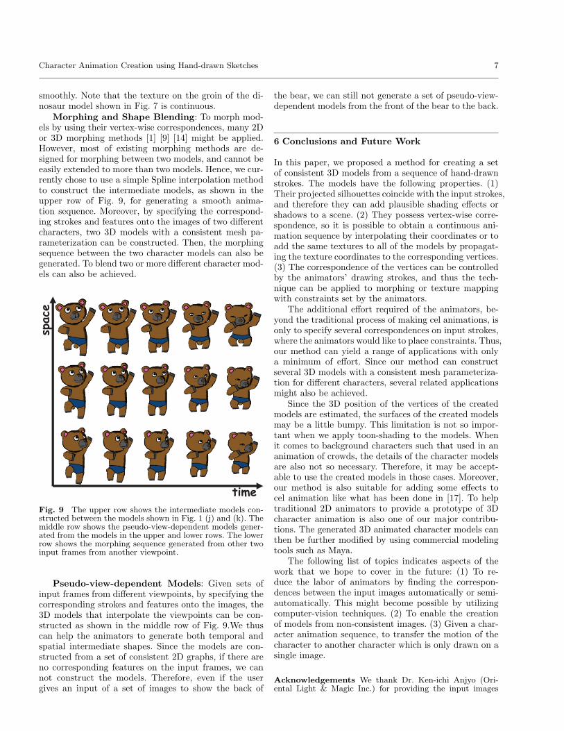
Morphing and Shape Blending: To morph mod-els by using their vertex-wise correspondences, many 2Dor 3D morphing methods [1] [9] [14] might be applied.However, most of existing morphing methods are de-signed for morphing between two models, and cannot beeasily extended to more than two models. Hence, we cur-rently chose to use a simple Spline interpolation methodto construct the intermediate models, as shown in theupper row of Fig. 9, for generating a smooth anima-tion sequence. Moreover, by specifying the correspond-ing strokes and features onto the images of two differentcharacters, two 3D models with a consistent mesh pa-rameterization can be constructed. Then, the morphingsequence between the two character models can also begenerated. To blend two or more different character mod-els can also be achieved.
time
space
Fig. 9 The upper row shows the intermediate models con-structed between the models shown in Fig. 1 (j) and (k). Themiddle row shows the pseudo-view-dependent models gener-ated from the models in the upper and lower rows. The lowerrow shows the morphing sequence generated from other twoinput frames from another viewpoint.
Pseudo-view-dependent Models: Given sets ofinput frames from different viewpoints, by specifying thecorresponding strokes and features onto the images, the3D models that interpolate the viewpoints can be con-structed as shown in the middle row of Fig. 9.We thuscan help the animators to generate both temporal andspatial intermediate shapes. Since the models are con-structed from a set of consistent 2D graphs, if there areno corresponding features on the input frames, we cannot construct the models. Therefore, even if the usergives an input of a set of images to show the back of
the bear, we can still not generate a set of pseudo-view-dependent models from the front of the bear to the back.
6 Conclusions and Future Work
In this paper, we proposed a method for creating a setof consistent 3D models from a sequence of hand-drawnstrokes. The models have the following properties. (1)Their projected silhouettes coincide with the input strokes,and therefore they can add plausible shading effects orshadows to a scene. (2) They possess vertex-wise corre-spondence, so it is possible to obtain a continuous ani-mation sequence by interpolating their coordinates or toadd the same textures to all of the models by propagat-ing the texture coordinates to the corresponding vertices.(3) The correspondence of the vertices can be controlledby the animators’ drawing strokes, and thus the tech-nique can be applied to morphing or texture mappingwith constraints set by the animators.
The additional effort required of the animators, be-yond the traditional process of making cel animations, isonly to specify several correspondences on input strokes,where the animators would like to place constraints. Thus,our method can yield a range of applications with onlya minimum of effort. Since our method can constructseveral 3D models with a consistent mesh parameteriza-tion for different characters, several related applicationsmight also be achieved.
Since the 3D position of the vertices of the createdmodels are estimated, the surfaces of the created modelsmay be a little bumpy. This limitation is not so impor-tant when we apply toon-shading to the models. Whenit comes to background characters such that used in ananimation of crowds, the details of the character modelsare also not so necessary. Therefore, it may be accept-able to use the created models in those cases. Moreover,our method is also suitable for adding some effects tocel animation like what has been done in [17]. To helptraditional 2D animators to provide a prototype of 3Dcharacter animation is also one of our major contribu-tions. The generated 3D animated character models canthen be further modified by using commercial modelingtools such as Maya.
The following list of topics indicates aspects of thework that we hope to cover in the future: (1) To re-duce the labor of animators by finding the correspon-dences between the input images automatically or semi-automatically. This might become possible by utilizingcomputer-vision techniques. (2) To enable the creationof models from non-consistent images. (3) Given a char-acter animation sequence, to transfer the motion of thecharacter to another character which is only drawn on asingle image.
Acknowledgements We thank Dr. Ken-ichi Anjyo (Ori-ental Light & Magic Inc.) for providing the input images
8 Bing-Yu Chen et al.
(Fig. 1). This work was partially supported by the NationalScience Council of Taiwan under the numbers: 93-2213-E-002-084.
References
1. Alexa, M., Cohen-Or, D., Levin, D.: As-rigid-as-possibleshape interpolation. In: Proc. SIGGRAPH 2000, pp. 157–164 (2000)
2. Bregler, C., Hertzmann, A., Biermann, H.: Recoveringnon-rigid 3d shape from image streams. In: Proc. CVPR2000, pp. 2690–2696 (2000)
3. Correa, W.T., Jensen, R.J., Thayer, C.E., Finkelstein,A.: Texture mapping for cel animation. In: Proc. SIG-GRAPH 98, pp. 435–446 (1998)
4. Fekete, J.D., Bizouarn, E., Cournarie, E., Galas, T.,Taillefer, F.: Tictactoon: A paperless system for profes-sional 2-d animation. In: Proc. SIGGRAPH 95, pp. 79–90(1995)
5. Freitag, L.A., Jones, M.T., Plassmann, P.E.: An efficientparallel algorithm for mesh smoothing. In: Proc. IMR95, pp. 47–58 (1995)
6. Igarashi, T., Matsuoka, S., Tanaka, H.: Teddy: A sketch-ing interface for 3d freeform design. In: Proc. SIG-GRAPH 99, pp. 409–416 (1999)
7. Kalnins, R.D., Davidson, P.L., Markosian, L., Finkel-stein, A.: Coherent stylized silhouettes. ACM TOG22(3), 856–861 (2003). (Proc. SIGGRAPH 2003)
8. Kalnins, R.D., Markosian, L., Meier, B.J., Kowalski,M.A., Lee, J.C., Davidson, P.L., Webb, M., Hughes, J.F.,Finkelstein, A.: Wysiwyg npr: Drawing strokes directlyon 3d models. ACM TOG 21(3), 755–762 (2002). (Proc.SIGGRAPH 2002)
9. Kanai, T., Suzuki, H., Kimura, F.: Metamorphosis of ar-bitrary triangular meshes. IEEE CG&A 20(2), 62–75(2000)
10. Karpenko, O., Hughes, J.F., Raskar, R.: Free-formsketching with variational implicit surfaces. ComputerGraphics Forum 21(3), 585–594 (2002). (Proc. Euro-graphics 2002)
11. Kraevoy, V., Sheffer, A., Gotsman, C.: Matchmaker: Con-structing constrained texture maps. ACM TOG 22(3),326–333 (2003). (Proc. SIGGRAPH 2003)
12. Li, Y., Gleicher, M., Xu, Y.Q., Shum, H.Y.: Stylizingmotion with drawings. In: Proc. SCA 2003, pp. 309–319(2003)
13. Martın, D., Garcıa, S., Torres, J.C.: Observer dependentdeformations in illustration. In: Proc. NPAR 2000, pp.75–82 (2000)
14. Michikawa, T., Kanai, T., Fujita, M., Chiyokura, H.:Multiresolution interpolation meshes. In: Proc. PG 2001,pp. 60–69 (2001)
15. Northrup, J.D., Markosian, L.: Artistic silhouettes: A hy-brid approach. In: Proc. NPAR 2000, pp. 31–38 (2000)
16. Ono, Y., Chen, B.Y., Nishita, T.: 3d character modelcreation from cel animation. In: Proc. CyberWorlds 2004,pp. 210–215 (2004)
17. Petrovic, L., Fujito, B., Williams, L., Finkelstein, A.:Shadows for cel animation. In: Proc. SIGGRAPH 2000,pp. 511–516 (2000)
18. Rademacher, P.: View-dependent geometry. In: Proc.SIGGRAPH 99, pp. 439–446 (1999)
19. Singh, K., Fiume, E.L.: Wires: A geometric deformationtechnique. In: Proc. SIGGRAPH 98, pp. 405–414 (1998)
20. Taubin, G.: Curve and surface smoothing without shrink-age. In: Proc. ICCV 95, pp. 852–857 (1995)
21. Torresani, L., Hertzmann, A., Bregler, C.: Learning non-rigid 3d shape from 2d motion. In: Proc. NIPS 2003, pp.577–580 (2003)
22. Winnemoller, H., Bangay, S.: Geometric approximationstowards free specular comic shading. Computer GraphicsForum 21(3), 309–316 (2002). (Proc. Eurographics 2002)
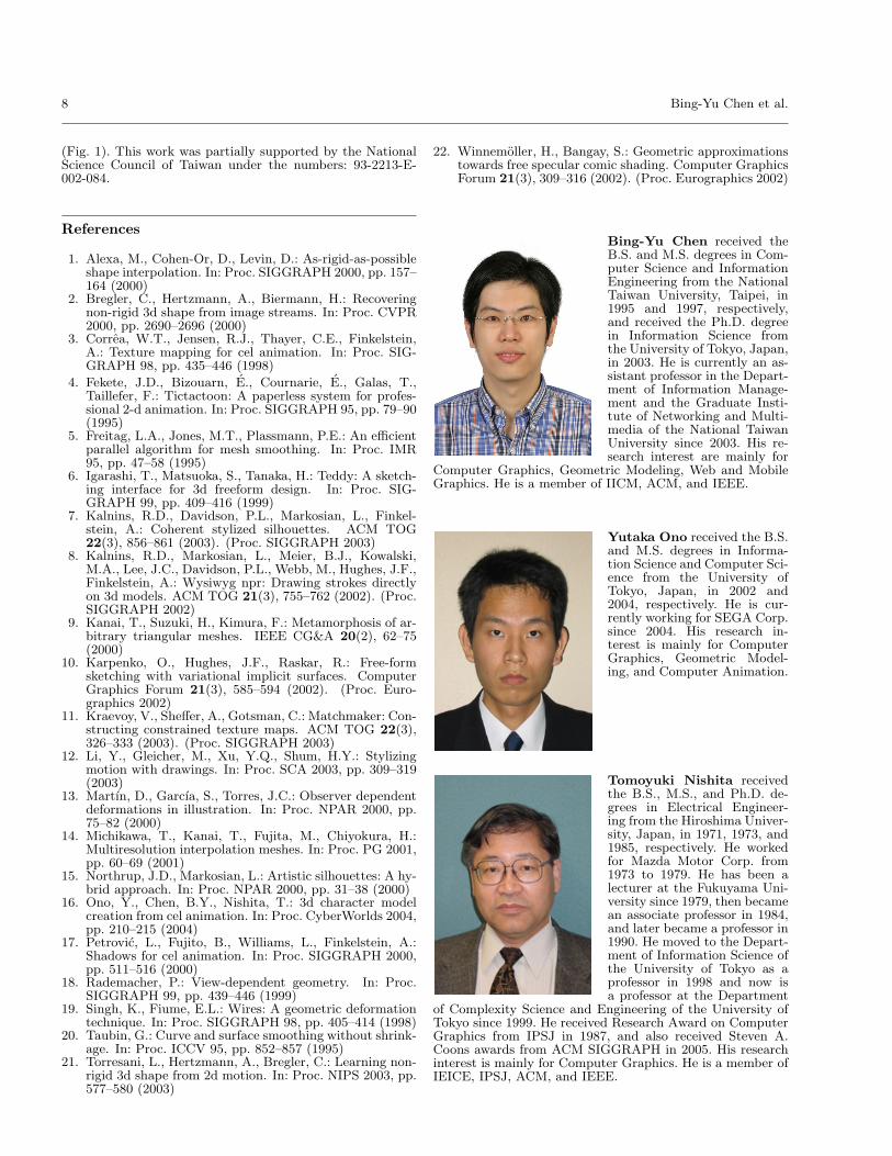
Bing-Yu Chen received theB.S. and M.S. degrees in Com-puter Science and InformationEngineering from the NationalTaiwan University, Taipei, in1995 and 1997, respectively,and received the Ph.D. degreein Information Science fromthe University of Tokyo, Japan,in 2003. He is currently an as-sistant professor in the Depart-ment of Information Manage-ment and the Graduate Insti-tute of Networking and Multi-media of the National TaiwanUniversity since 2003. His re-search interest are mainly for
Computer Graphics, Geometric Modeling, Web and MobileGraphics. He is a member of IICM, ACM, and IEEE.
Yutaka Ono received the B.S.and M.S. degrees in Informa-tion Science and Computer Sci-ence from the University ofTokyo, Japan, in 2002 and2004, respectively. He is cur-rently working for SEGA Corp.since 2004. His research in-terest is mainly for ComputerGraphics, Geometric Model-ing, and Computer Animation.
Tomoyuki Nishita receivedthe B.S., M.S., and Ph.D. de-grees in Electrical Engineer-ing from the Hiroshima Univer-sity, Japan, in 1971, 1973, and1985, respectively. He workedfor Mazda Motor Corp. from1973 to 1979. He has been alecturer at the Fukuyama Uni-versity since 1979, then becamean associate professor in 1984,and later became a professor in1990. He moved to the Depart-ment of Information Science ofthe University of Tokyo as aprofessor in 1998 and now isa professor at the Department
of Complexity Science and Engineering of the University ofTokyo since 1999. He received Research Award on ComputerGraphics from IPSJ in 1987, and also received Steven A.Coons awards from ACM SIGGRAPH in 2005. His researchinterest is mainly for Computer Graphics. He is a member ofIEICE, IPSJ, ACM, and IEEE.