Embed Size (px)
Citation preview

0

1
An-Najah National University
Faculty of EngineeringCivil Engineering Department
Zara CenterNew Building Footing Design
Prepared byMohammad Samaaneh
SupervisorDr. Sami Hijjawi
May 2009

2
اإلهداءإلى من كانوا أول حياتي , إلى من أسسوا لي أمنياتي
إليكم أبي وأمي إلى من علموني أن النجاح مستقبل كل مثابر, وأن
الفوز حليف كل مناضلإليكم أساتذتي األفاضل
إلى من حضنتني بحبها , وزودتني بمعرفتها وعلمهاإليك جامعة النجاح الوطنية
إلى تالل الزيتون والزعتر , إلى رائحة العود والعنبروطني الحبيب
والحمد لله رب العالمينمحمد عبدا لرحمن سماعنه
Table of ContentsSubject Page
Chapter One : Introduction 51:1 General requirements for footing 6

3
1:2 Project description 71:3 Selection Type of Footing 7
Chapter Two :Literature Review 2:1 Soil Mechanics 8 2:1:1 Type of soil 8 2:1:2 Specification of soil 10 2:1:3 Shear strength of Soil 11 2:1:4 Soil Compaction 13 2:1:5 Soil stability 14 2:1:6 Soil settlement 15 2:1:7 Site Investigation 172:2 Foundations 21 2:2:1Introduction for Footing 21 2:2:2 Isolated Footings 22 2:2:3 Combined Footings 26 2:2:4 Mat (Raft ) Foundations 29 2:2:5 Pile foundations 32 2:2:5:1 Types of Piles 33 2:2:5:2 Estimating Pile Length 39 2:2:6 Settlement of Foundations 422:3 Load Transfer 46
Chapter Three : Site Investigation & Soil report3:1 Introduction 503:2 Purpose of the study 503:3 Site Investigation 51 3:3:1 Site Conditions 51 3:3:2 Water Level 54 3:3:3 Settlement Analysis 54
Chapter Four :Design of Foundations4:1 Structural Analysis 554:2 Design of Single Footing 57 4:2:1Determine Area of Footing 57 4:2:2 Elastic settlement 58 4:2:3 Thickness of Single Footing 63

4
4:2:4 Steel Reinforcement 67 4:2:5 Tie Beam Design 73 4:2:6 Design a small mat footing 75 4:2:7 Summaries of Dimensions & reinforcements 824:3 Design of Combined Footing 864:4 Design of Wall footing 984:5 Mat (Raft) Foundation 100 4:5:1 Design of mat foundation 100 4:5:2 Settlement of mat foundation 110
Chapter Five : References & Appendices
Chapter One
Introduction

5
A footing can be defined as a structural element that used to
connect structure with soil, and usually placed below the ground
surface (substructure). These elements must be safe to transfer
loads in a way that pressure over the soil less than soil bearing
capacity, load pressure will be reduced as going down through the
soil because the load will be divided for a larger area as shown in
the following figure:
Figure (1:1) soil pressure under footing
1:1 General requirements for footing
A footing must be able to satisfy the following requirements:
1) Footing area must be able to carry load and transfer it safely to the soil.

6
2) Footing depth must be adequate to avoid the footing from volume changes, freezing and atmospheric effects.
3 )Footing must be able to prevent structure movement, sliding and overturning.
4 )Footing settlement and differential settlement must be acceptable for footing and total structure.
5 )Economical consideration must be considered through construction.
6 )Structure safety must be first.
Depending on these requirements, type of footing and method of construction can be determined .
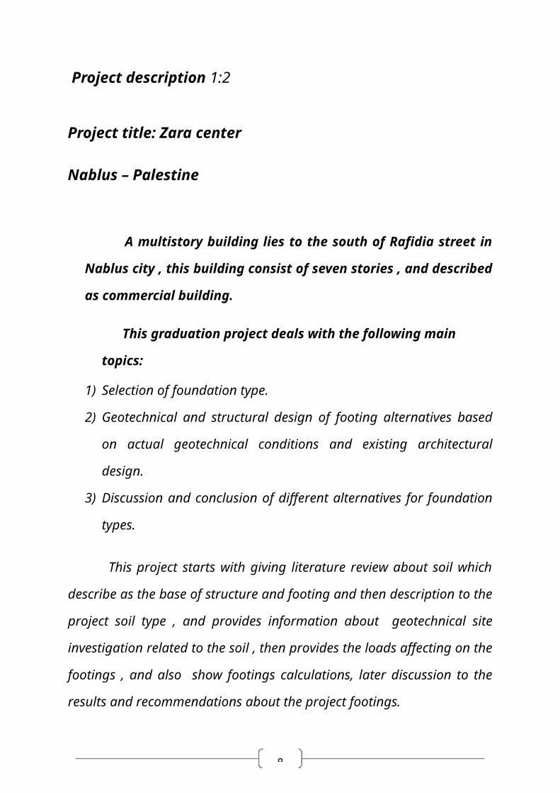
1:2 Project description
Project title: Zara center
Nablus – Palestine

7
A multistory building lies to the south of Rafidia street in Nablus city ,
this building consist of seven stories , and described as commercial
building.
This graduation project deals with the following main topics:
1) Selection of foundation type.
2) Geotechnical and structural design of footing alternatives based on
actual geotechnical conditions and existing architectural design.
3) Discussion and conclusion of different alternatives for foundation types.
This project starts with giving literature review about soil which describe as
the base of structure and footing and then description to the project soil type ,
and provides information about geotechnical site investigation related to the
soil , then provides the loads affecting on the footings , and also show footings
calculations, later discussion to the results and recommendations about the
project footings.
1:3 Selection type of footing:
There are many factors affecting selection types of footing such as soil
bearing capacity, loads to be transfer to the soil, economical conditions in
addition to the available technology, these factors will be discussed in the
project.
Chapter Two
8
Literature Review
2:1) Soil Mechanics
2:1:1) Types of soil
Soils are classified by the fractions of each soil separate (sand, silt, and clay)
present in a soil. Classifications are typically named for the primary constituent
particle size or a combination of the most abundant particles sizes, e.g. "sandy
clay" or "silty clay." A fourth term, loam, is used to describe a roughly equal
concentration of sand, silt, and clay, and lends to the naming of even more
classifications, e.g. "clay loam" or "silt loam."
a) Gravel: This type of soil has the biggest particle, and considered as a
granular soil , this size is very important in construction and in
engineering work .
b) Sandy Soil: This type has the biggest particles after gravel and the size of
the particles determine the degree of aeration and drainage that the soil
allows, it is granular and consists of rock and mineral particles that are
very small.
c) Silty Soil: Silty soil is considered to be one of the most fertile soils, it can
occur in nature as soil or as suspended sediment in water column of a
water body on the surface of the earth, it is composed of minerals like
Quartz and fine organic particles, it is granular like sandy soil but it has
more nutrients than sandy soil and it also offers better drainage.
d) Clay Soil : Clay is a kind of material that occurs naturally and consists of
very fine grained material with very less air spaces, that is the reason it is

9
difficult to work with since the drainage in this soil is low. Clay soil
becomes very heavy when wet.
e) Loamy Soil: This soil consists of sand, silt and clay to some extent, it is
considered to be the perfect soil, the texture is gritty and retains water
very easily, yet the drainage is well.
f) Other types of soil :Peaty Soil, chalky soil ,and other type of soil :
Every soil type behaves differently with respect to maximum density and
optimum moisture. Therefore, each soil type has its own unique requirements
and controls both in the field and for testing purposes. Soil types are commonly
classified by grain size, determined by passing the soil through a series of sieves
to screen or separate the different grain sizes (sieve analysis test). Soils found in
nature are almost always a combination of soil types.
From the result of sieving (which consider one of the most tests to determine
soil type and soil characteristic you can determine the graded of soil:
1) Well graded.
2) Poorly graded.
3) Gap graded.
See figure (2:1) which represent typical curves of sieve analysis particle size

10
Figure (2:1) Typical curves of Sieve analysis particle size
A well-graded soil consists of a wide range of particle sizes with the smaller
particles filling voids between larger particles, the result is a dense structure
that lends itself well to compaction. A soil's makeup determines the best
compaction method to use.
2:1:2) Specification of soil:
Using these specification, the soil can be classified and determine the class of
each soil.
Using AASHTO (American Association of State Highway and Transportation
Officials):
Gravel à (76.2 – 2) mm.
Sand à (2 – 0.075) mm.
Silt à (0.075 – 0.002) mm.
Clay à (< 0.002) mm.
Using USCS (Unified Soil Classification System):

11
Gravel à (76.2 – 4.75) mm.
Sand à (4.75 – 0.075) mm.
Fines (silt + clay) à (< 0.075) mm.
Soil type is important to determine type of footing to be used in addition to
required treatment process ( if necessary ).
2:1:3 )Shear Strength of soil
The shear strength of a soil mass is the internal resistance per unit area that
the soil mass can offer to resist failure and sliding along any plane inside it ,
understanding the nature of shearing resistance in order to analyze soil
stability problems, such as bearing capacity , slope stability ,and lateral
pressure on earth-retaining structures .
it is sufficient to approximate the shear stress on failure plane as a linear
function of the normal stress ( coulomb,1776). This linear function can be
written as:
τf = c+σ tanФ ………… equ(2:1)
For pure sand the equation becomes: τf =σ tanФ where c≈0 in sand
For only clay the equation becomes: τf =c where Ф ≈0 in clay
Where:
c= cohesion.
Ф=angle of internal friction.
σ =normal stress on the failure plane.
τf = shear strength.
The preceding equation is called the Mohr-Coulomb failure criterion.

12
The significance of the failure envelope can be explained as following [2]:
If the normal stress and shear stress on a plane in soil mass are such that they
plot as point A in figure (2:2), Shear failure will not occur along that plane. If
the normal stress and shear stress on a plane plot as point B (which falls on the
failure envelope), shear failure will occur along that plane. A state of stress on
a plane represented by point C cannot exit, since it plots above the failure
envelope, and shear failure in a soil would have occurred already.
Figure
(2:2) Mohr’s –Coulomb failure law
The shear strength parameter of soil can be determined in the lab primarily
by two types of tests: direct test and triaxial test.

13
2:1:4 )Soil compaction:
Soil compaction is defined as the method of mechanically increasing the
density of soil. In construction, this is a significant part of the building process,
if performed improperly, settlement of the soil could occur and result in
unnecessary maintenance costs or structure failure, almost all types of building
sites and construction projects utilize mechanical compaction techniques.
There are many principle reasons to compact soil:
1 (Increases load-bearing capacity.
2 (Prevents soil settlement and frost damage.
3 (Provides stability.
4 (Reduces water seepage, swelling and contraction.
5 (Reduces settling of soil.
6 (Increase unit weight.
7 (Increase stability of soil.
Two principle types of compaction force: static and vibratory
Static force is simply the deadweight of the machine, applying downward
force on the soil surface, compressing the soil particles. The only way to
change the effective compaction force is by adding or subtracting the weight of
the machine. Static compaction is confined to upper soil layers and is limited to
any appreciable depth. Kneading and pressure are two examples of static
compaction.

14
2:1:5 )Slope stability:
An exposed ground surface that stands at an angle with the horizontal is
called an unrestrained slope. The slope can be natural or more man-made. If
the ground surface is not horizontal, a component of gravity will tend to move
the soil downward, when the component of gravity is large enough, slope
failure can occur; that is the soil mass in the zones can slide downward. In other
words, the driving force overcomes the resistance derived from the shear
strength of the soil along the rupture surface.
Civil engineers often are expected to make calculations to check the safety
of natural slopes, slope excavations, and compacted embankments. This check
involves determining the shear stress developed along the most likely rupture
surface and comparing it with the shear strength of the soil, this process is
called slope stability analysis. The most likely rupture surface is critical surface
that has the minimum factor safety, see figure (2:3) which show an isolated
footing near a slope.
Figure (2:3) isolated footing near a slope

15
2:1:6 )Soil settlement (compressibility of soil)
Superimposed load causes soil layers to undergo a certain amount of
compression due to deformation of soil particles, relocation of soil particles,
expulsion of water or air from the void spaces, and other reasons. Some or all
of these factors may be associated with a given soil condition. In general, the
settlement caused in soil due to loading may be divided into two broad
categories:
1 )Consolidation settlement:
Which is the result of volume change in saturated soils due to the expulsion
of water occupying the void spaces, when a saturation soil layer is subjected to
a stress increase, the pore water pressure is increased suddenly. In sandy soils
that are highly permeable, the drainage caused by the increase in the pore
water pressure is completed immediately, pore water drainage is accompanied
by a reduction in the volume of the soil mass , which results in
settlement ,because of rapid drainage of the pore water in sandy soils , elastic
settlement and consolidation occur simultaneously.
2 )Elastic settlement:
This is due to the elastic deformation of dry, moist and saturated soils
without any change in the water content. Elastic settlement calculations are
generally based on equations derived from theory of elasticity.
There are two type of elastic settlement depending on the type of foundation:

16
1 )Flexible foundation.
2 )Rigid foundation.
Where most of the elastic settlement of foundations occurs immediately after
the application of load without change of moisture content .The magnitude of
the contact settlement will depend on the flexibility of the foundation and the
type of material on which it is resting.
A uniformly loaded, perfectly flexible foundation resting on an elastic material
such as saturated clay will take a sagging profile, as shown in figure (2:4) due
to elastic settlement. However, if the foundation is rigid and is resting on an
elastic material such as clay, it will undergo uniform settlement and the contact
pressure will undergo redistribution as shown in figure (2:5).
Figure (2:4) Flexible foundation

17
Figure (2:5) Rigid foundation
Settlement is important in soil and in foundation, so this topic will be
discussed later in the foundation section, but in that section specific for
foundation
2:1:7 )Site investigations
a) General requirements:
A site investigation is always required for any engineering or building
structure, the investigation may range in scope from a simple examination of
the surface soils with or without a few shallow trial pits to a detailed study of
the soil and ground water conditions to a considerable depth below the surface
by means of boreholes and in-situ and laboratory tests on the material
encountered.
Whatever procedure the engineer adopts for carrying out his investigation
work it is essential that the individuals or organization undertaking the work
should be conscientious and completely reliable. The engineer has an important
responsibility to his employers in selecting a competent organized and in

18
satisfying himself by checks in the field and on laboratory or office work that
has been undertaken with accuracy and thoroughness.
b) Objectives of site investigation:
1 (Selecting type and depth of foundations.
2 (Evaluating the bearing capacity at any depth.
3 (Settlement coefficients.
4 (Determination of problems potential.
5 (Location of water table.
6 (Lateral earth pressure.
7 (Construction method.
c) Information required from a site investigation :
The following information should be obtained in the site investigation for
foundation engineering purposes:
1 (The general topography of the site as it affects foundation and construction,
e.g. surface configuration, adjacent property.
2 (The location of buried services such as electric power, water mains.
3) The previous history and use of the site including information on any defects
or failure of exiting or former buildings attributable to foundation conditions
and the possibility of contamination of the site by toxic waste materials .

19
4 (General geology of the area with particular Reference to the main geological
formations underlying the site and the possibility of subsidence from mineral
extraction.
5) A detailed record of the soil and rock strata and ground-water conditions
within the zones affected by foundation bearing pressures and construction
operations.
6 (Results of field and laboratory tests on soil.
d) Borehole layout:
Whenever possible boreholes should be sunk close to proposed foundations,
this is important where the bearing stratum is irregular in depth, for the same
reason the boreholes should be accurately located in position and level in
relation to proposed structures.
The required number of boreholes which need to be sunk on any particular
location is a difficult problem which is closely bound up with the relative costs
of the investigation and the project for which it is undertaken.
Next tables show spacing between boreholes and depth of boreholes in table
(2:1) & (2:2) respectively [1].

20
Type of project
SpacingSpacing
(m)(ft)
Multistory building10 -3030 – 100
One – story industrial
plants20 -6060 – 200
Highways250 - 500800 – 1600
Residential subdivision250 - 500800 – 1600
Dams and dikes40 - 80130 – 260Table (2:1) Spacing between boreholes
Approximate depths of Boreholes
Boring depthNo. of stories
11 ft3.5 m1
20 ft6 m2
33 ft10 m3
53 ft16 m4
79 ft24 m5Table (2:2) Depth of boreholes
2:2) Foundations

21
2:2:1) Introduction for footing
The bottom part of a structure generally is referred to as the foundation; its
function is to transfer the load of the structure to the soil on which it is resting.
A properly designed foundation transfers the load throughout the soil without
overstressing the soil, both of which cause damage to the structure. Thus,
geotechnical and structural engineers who design foundations must evaluate
the bearing capacity of soils.
Depending on the structure and soil encountered, various types of foundations
are used:
A spread footing (shallow footing) is simply an enlargement of a load
bearing wall or column that makes it possible to spread the load of the
structure over larger area of the soil in soil with low load bearing capacity, the
size of the spread footing requires is impracticably large, in that case, it is more
economical to construct the entire structure over a concrete pad, this is called a
mat foundation.
Pile and drilled shaft foundations (deep footing) are used for heavier
structures when great depth is required for supporting the load. Piles are
structural members made of timber, concrete, or steel that transmit their load
into the subsoil, piles can be divided into two categories: friction piles and end
bearing piles. In the case of friction piles, the superstructure load is resisted by
the shear stress generated along the surface of the pile.
Spread footings and mat foundations generally are referred to as shallow,
where pile and drilled-shaft foundations are classified as deep foundations.

22
In more general sense, shallow foundations are foundations that have a
depth of embedment to width ratio of approximately less than four. When the
depth of embedment to width ratio of a foundation is greater than four, it may
be classified as a deep foundation.
Many types of foundation will be discussed in this section .
2:2:2 )Isolated footing
To perform satisfactorily, shallow foundations must have two main
characteristics:
1 (They have to be safe against overall shear failure in the soil that supports
them.
2) They cannot undergo excessive displacement, or settlement. (The term
excessive is relative, because the degree of settlement allowed for a structure
depends on several considerations).
The load per unit area of the foundation at which shear failure in soil occurs is
called ultimate bearing capacity.
General concepts
Consider a strip foundation with a width of B resting on the surface of a
dense sand or stiff cohesive soil, as shown in figure (2:6). Now, if a load is
generally applied to the foundation, settlement will increase. The variation of
the load per unit area, with the foundation settlement on the foundation “q”, is
also shown in figure (2:6), at a certain point when the load per unit area “q” a

23
sudden failure in the soil supporting the foundation will take place, and the
failure surface in the soil will extended to the ground surface. This load per unit
area” q” is usually referred to as the ultimate bearing capacity of the
foundation. When such sudden failure in the soil takes place, it is called general
shear failure.

24
Figure(2:6) General shear failure
If the footing rests on sand and clayey soil of medium compaction, in
increase in the load on the foundation will also be accompanied by an increase
in settlement. However, in this case the failure surface in the soil will gradually
extend outward from the foundation, as shown by the solid lines in figure (2:7).
When the load per unit area on the foundation equals q(1), movement of the
foundation will be accompanied by sudden jerks. A considerable movement of
the foundation as then required for the failure surface in soil to extend to the
ground surface (as shown by the broken lines in the figure). The load per unit
area at which this happens is the ultimate bearing capacity, “q” beyond that
point, an increase in load will be accompanied by a large increase in foundation
settlement.
The load per unit area of the foundation, q(1), is referred to as the first
failure load(Vesic, 1963). Note that a peak value of q is not realized in this type
of failure, which is called the local shear failure in soil.

25
Figure(2:7) local shear failure
If the footing is supported by a fairly loose soil, the load-settlement plot will be
like the one in figure (2:8). In this case, the failure surface in soil will not extend
to the ground surface. Beyond the ultimate failure load, q, the load-settlement
plot will be steep and practically linear, this type of failure in soil is called the
punching shear failure.

26
Figure(2:8) punching shear failure
2:2:3 )Combined Footings
Introduction:
The preceding section presented elements of the design of spread footing.
This section considers some of the more complicated shallow-foundation
problems. Among these are footings supporting more than one column in a line

27
(combined footings), which may be rectangular or trapezoidal in shape, or two
pads connected by a beam, as for a strap footing. Eccentrically loaded footings
and un-symmetrically shaped footings will also be considered.
a) Rectangular Combined Footings
When property lines, equipment locations, column spacing, or other
considerations limit the footing clearance at the column locations, a possible
solution is the use of a rectangular-shaped footing. This type of footing may
support two columns, as illustrated in Figure (2:9), or more than two columns
with only slight modification of the design procedure. These footings are
commonly designed by assuming a linear stress distribution on the bottom of the
footing, and if the resultant of the soil pressure coincides with the resultant of
the loads (and center of gravity of the footing), the soil pressure is assumed to be
uniformly distributed; the linear pressure distribution implies a rigid footing on a
homogeneous soil. The actual footing is generally not rigid, nor is the pressure
uniform beneath it, but it has been found that solutions using this concept are
adequate. This concept also results in a rather conservative design.
Figure (2:9) Rectangular combined footing

28
b) Trapezoidal Combined footing:
Trapezoidal combined footing for two columns used when one column carries
load more than another where the projection is limited or when there is
restriction on the total length of the footing as in Figure(2:10).
The position of the resultant of columns loads R locates the position of the
centriod of the trapezoid.
The design procedure is the same as rectangular combined footing except that
the shear diagram will be a second degree curve and bending moment is a third
degree curve.
Figure (2:10) Trapezoidal combined footing
c) Strap or Cantilever Footings

29
A strap footing may be used where the distance between columns is so great
that a combined or trapezoid footing becomes quite narrow, with resulting high
bending moments.
A strap footing consists in two column footings connected by a member
termed a strap, beam, or cantilever which transmits the moment from the
exterior footing, see figure (2:11) that show strap footing
Figure (2:11) strap footing
2:2:4 )Mat or Raft Foundations
The raft foundation is continuous footing that covers the entire area beneath
a structure and supports all the walls and columns. The term mat is also used
for foundation of this type. It is used generally on soil of low bearing capacity
and where the area covered by spread footings is more than half the area
covered by the structure. Raft foundation is also used where the soil mass
contains compressible lenses or the soil is sufficiently erratic so that differential
settlement would be difficult to control. The raft tends to bridge over erratic
deposits and reduces the differential settlement.

30
Mat foundations are generally used with soil that has a low bearing capacity.
There are many types of raft foundations:
1) Flat slab raft which is an inverted flat slab Figure (2:12-a). If the thickness
of the slab is not enough to resist punching shear under columns, pedestals
may be .used above the slab Figure (2:12-b) or, below the .slab, by thickening
the flat slab under the columns as shown in Figure(2:12-c).
2) Slab and girder raft which, is. An inverted R.C. floor, composed of slabs and
beams extending along column, rows in both directions, Figure (2:12-d), it is
also, termed ribbed mat. If a continuous floor is desired in the basement, the
ribs (beams) may be placed beneath the slab, Figure (2:12-e).

31
Figure(2:12) Raft foundation
See figures (2:13) & (2:14) which show types of mat foundation

32
Figure (2:13) mat foundation
Figure (2:14) mat foundation
2:2:5) Pile foundations:

33
Piles are structural member that are made of steel, concrete, or timber. They
are used to build pile foundations, which are deep and which cost more than
shallow foundations. Despite the cost, the use of piles often is necessary to
ensure structural safety. The following list identifies some of the conditions that
required pile foundations:
1) When one or more upper soil layers are highly compressible and too weak to
support the load transmitted by the superstructure, piles are used to transmit
the load to underlying bedrock or a stronger soil layer.
2) In many cases, expansive soil and collapsible soils may be present at the site
of a proposed structure. These soils may extend to a great depth below the
ground surface. Expansive soil swell and shrink as their moisture content
increases or decreases .If shallow foundations are used in such circumstances;
the structure may suffer considerable damage. Pile foundation may be used in
which the piles are extended into stable soil layer beyond the zone where
moisture will change.
3) The foundations of some structures such as transmission towers, offshore
platforms. And basement mats below the water table are subjected to uplifting
forces. Piles are sometimes used for these foundations to resist uplifting force.
4) Bridge abutments and piers are usually constructed over pile foundations to
avoid the loss of bearing capacity that shallow foundation might suffer because
of soil erosion at the ground surface.

34
2:2:5:1) Types of piles and their structural characteristics:
Different types of piles used in construction work, depending on the type of
load to be carried, the subsoil conditions, and the location of the water table.
Piles can be divided into the following categories: (a) steel piles, (b) concrete
piles, (c) wooden piles, (d) composite piles .
a) Steel piles:
Steel piles generally are either pip piles or rolled steel H-section piles. Pipe piles
can be driven into the ground with their ends open or closed. Wide-flange and I
section steel beams can also be used .however H-section piles are usually
preferred because their web and flange thicknesses are equal .usually the pipe
piles are filled with concrete after they have been driven.
The allowable structural capacity for steel piles is
Qall=As*fs …..…equ(2:2)
Where :
As: cross-sectional area of the steel.
fs :allowable stress of steel (≈0.33-0.5fy)
Following are some general facts about steel piles:
1) Usual length: 15m-60m (50ft-200ft).
2) Usual load: 300 *1200 KN
3) Advantages:

35
a) Easy to handle with respect to cutoff and extension to the desired length .
b) Can stand high driving stresses.
c) High load-carrying capacity.
4) Disadvantages:
a) Relative costly.
b) High level of noise during pile driving.
c) Subject to corrosion.
b) Timber piles:
Timber piles are tree trunks that have had their branches and bark carefully
trimmed off. The maximum length of most timber piles is 10-20 m (30-65 ft)
To qualify for use as a pile, the timber should be straight, sound, and without
any defects.
Advantages of wooden piles:
1) Cheap.
2) Widely available
Disadvantages of wooden piles:
1) Timber piles cannot withstand hard driving stress.
2) When located above the water table, the pile is subject to attack by insects.
3) In a marine environment, timber piles are subjected to attack by various
organisms and can be damaged extensively in a few months.

36
c) Concrete piles:
Concrete piles may be divided into two basic categories:
1) Precast piles 2) Cast in-situ piles.
Precast piles can be prepared by using ordinary reinforcement, and they can be
square or octagonal in cross section .see figure (2:15).
Reinforcement is provided to enable the pile to resist the bending moment
developed
During pickup and transportation, the vertical load, and the bending moment
caused by a lateral load .the piles are cast to desired length and cured before
being transported to the work sites.
Figure (2:15) précised pile
Some general facts about concrete piles are as follow:

37
1) Usual length:10-15 m (30-50 ft)
2) Usual load : 300-3000 KN
3) Advantages:
a) Can be subjected to hard driving.
b) Corrosion resistant.
c) Can be easily combined with a concrete superstructure.
4) Disadvantages:
a) Difficult to achieve proper cutoff.
b) Difficult to transport.
c) Environmental effect.
Cast-in-situ, piles are built by making a hole in the ground and then filling it
with concrete .Various types of cast in situ concrete piles are currently used in
construction, and most of them have been patented by their manufacturers.
These piles may be divided into two board categories:
a) Cased b) uncased
Both types may have a pedestal at the bottom. Cased piles are made by driving
a steel casing into the ground with the help pf a mandrel placed inside the
casing. When the pile reaches the proper depth the mandrel is withdrawn and
the casing is filled with concrete.
Figure (2:16-a) show cased pile without a pedestal, figure (2:16-b) show a
cased pile with a pedestal. Where the pedestal is an expanded concrete bulb
that is formed by dropping a hammer on fresh concrete.

38
Figure (2:16) cased and uncased piles
Some general facts about cased in-situ piles are as follows:
1) Usual length: 5-15 m.
2) Maximum length: 30-40 m.
3) Approximately maximum load: 800KN.
4) Usual load: 200 -500 KN.
5) Advantages:
a) Relative cheap.
b) Allow for inspection before pouring concrete.
c) Easy to extend.
6) Disadvantages:

39
a) Difficult to splice after concreting.
b) Thin casing may be damaged during driving.
7) Allowable load:
Qall= As*fs + Ac*fc ………..equ(2:3)
Where
Ac :Area of cross section of concrete
As: Area of cross section of steel
fs: Allowable stress of steel
fc: Allowable stress of concrete
Figures (2:16-c)(2:16-d ) that shown before are two types of uncased pile ,one
with a pedestal and other without. The uncased piles are made by first driving
the casing to the desired depth and then filling it with fresh concrete. The
casing is then gradually withdrawn.
Some general facts about uncased in-situ piles are as follows:
1) Usual length: 5-15 m.
2) Maximum length: 30-40 m.
3) Usual load: 300-500 KN.
4) Maximum load: 700 KN.
5) Advantage: economic and can be finished at any elevation.
6) Disadvantage: difficult to splice after concreting and voids may be created if
concrete is placed rapidly.
7) Allowable load:

40
Qall=Ac*fc ………..equ(2:4)
Where Ac :area of cross section of concrete
fc: allowable stress of concrete.
2:2:5:2) Estimating pile length:
Selecting the type of pile to be used and estimating its necessary length are
fairly difficult tasks that require good adjustment. In addition to being broken
down into the classification given in section (2:2:5:1) piles can be divided into
three major categories, depending on their lengths and mechanism of load
transfer to the soil:
1) Point bearing piles:
If soil-boring records establish the presence of bedrock or rocklike material at
a site within a reasonable depth, piles can be extended to the rock surface. See
figure (2:17-a).
In the case, the ultimate capacity of the piles depends entirely on the load-
bearing capacity of the underlying material; thus, the piles are called point
bearing piles. In most of these cases, the necessary length of the pile can be
fairly well established.
Instead of bedrock, a fairly compact and hard stratum of soil is encountered at
a reasonable depth; piles can be extended a few meters into the hard stratum.
See figure (2:17-b).
Piles with pedestals can be constructed on the bed of the hard stratum, and the
ultimate pile may be expressed as:

41
Qu = Qp + Qs …….……equ(2:5)
Where:
Qp: load carried at the pile.
Qs: load carried by skin friction developed at the side of the pile.
2) Friction piles:
When no layer of rock or rocklike material is present at a reasonable depth
at a site, point bearing piles become very long and uneconomical. In this type of
subsoil, piles are driven through the softer material to specified depths. See
figure (2:17-c).
These piles are called friction piles, because most of their resistance is derived
from skin friction. However, the term friction pile, although used often in the
literature, is a misnomer: in clayey soils, the resistance to applied load is also
caused by adhesion.
The lengths of friction piles depend on the shear strength of the soil, the
applied load, and the pile size. To determine the necessary lengths of these
piles, an engineer needs a good understanding of soil-pile interaction, good
judgment, and experience.
3) Compaction piles:

42
Under certain circumstances, piles are driven in granular soils to achieve
proper compaction of soil close to the ground surface. These piles are called
compaction piles. The lengths of compaction piles depend on factors such as:
a ) The relative density of the soil before compaction.
b )The desired relative density of the soil after compaction.
c ) The require depth of compaction.
These piles are generally short; however, some field tests are necessary to
determine a reasonable length.
Figure (2:17) mechanism of load transfer in plies
2:2:6) Settlements of Foundations:

43
In order to complete settlement topics which start in section (2:1:6), so this
section talks about settlement in foundation.
Settlement due to consolidation of foundation soil is usually the most
important consideration in calculating the serviceability limit state or in
assessing allowable bearing pressures where permissible stress methods are
used. Even though sinking of foundations as a result of shear failure of the soil
has been safeguarded by ultimate limit state calculations or by applying an
arbitrary safety factor on calculated ultimate bearing capacity, it is still
necessary to investigate the likelihood of settlements before the allowable
bearing pressures can be fixed.
The settlement of a structural foundation consists of three parts:
1) Immediate settlement: takes place during application of the loading as a
result of elastic deformation of the soil without change in water content.
2) Consolidation settlement takes place as a result of volume reduction of the
soil caused by extrusion of some of the pore water from the soil.
3) Creep or secondary settlement occurs over a very long period of years after
completing the extrusion of excess pore water.
See figure (2:18) which show settlement stages with time.
If deep excavation is required to reach foundation level, swelling of the soil take
place as a result of removal of the pressure of the overburden. The magnitude

44
of the swilling depends on the depth of overburden removed and the time the
foundations remain unloaded.
Figure (2:18) Settlement stages with time
In the case of foundations on medium-dense to dense sands and gravels, the
immediate and consolidation settlement are of relatively small order. A high
proportion of the total settlement is almost completed by the time the full
loading comes on the foundations. Similarly, a high proportion of the
settlement of foundations on loose sands takes place as the load is applied,
whereas settlements on compressible clays are partly immediate and partly
long term movements.
Differential settlement between parts of a structure may occur as a result of the
following:

45
1) Variations in foundations loading.
2) Large loaded areas on flexible foundations.
3) Differences in time of construction of adjacent parts of structures.
4) Variation in site conditions.
5) Overlapping stresses.
6) Soil Permeability.
7) Soil Drainage.
8) Variations in strata.
If the structures themselves have insufficient rigidity to prevent excessive
differential movement with ordinary spread foundations, one or a combination
o the following methods may be adopted in order to reduce the total and
differential settlements:
1) Provision of a rigid raft foundation either with a thick slab or with deep
beams in two or three directions.
2) Provision of a deep basements to reduce the net bearing pressure on the soil.
3) Transference of foundation loading to deeper and less compressible soil by
means of basement, piers, or piles.
4) Provision of jacking pockets, or brackets, in columns to reveal the
superstructure.

46
2:3 )Load Transfer
Footings are structural members used to support columns and walls and to
transmit and distribute their loads to the soil in such a way that the load
bearing capacity of the soil is not exceeded, excessive settlement, differential
settlement, or rotation are prevented and adequate safety against overturning
or sliding is maintained.
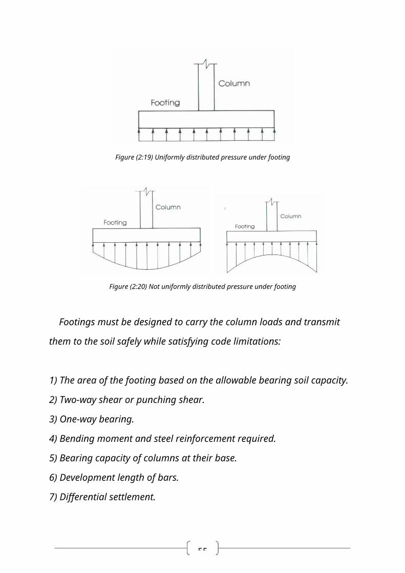
When the column load P is applied on the centroid of the footing, a uniform
pressure is assumed to develop on the soil surface below the footing area as in
figure (2:19). However the actual distribution of the soil is not uniform, but
depends on may factor especially the composition of the soil and degree of
flexibility of the footing as in figure (2:20).
Figure (2:19) Uniformly distributed pressure under footing

47
Figure (2:20) Not uniformly distributed pressure under footing
Footings must be designed to carry the column loads and transmit them to
the soil safely while satisfying code limitations:
1) The area of the footing based on the allowable bearing soil capacity.
2) Two-way shear or punching shear.
3) One-way bearing.
4) Bending moment and steel reinforcement required.
5) Bearing capacity of columns at their base.
6) Development length of bars.
7) Differential settlement.
The area of footing can be determined from the actual external loads such that
the allowable soil pressure is not exceeded.
.......equ(2:6)
…….equ(2:7)
Area of footing =Total load ( including self-weight )allowable soil pressure
qu=Pu
area of footing

48
The bending moment in each direction of the footing must be checked and the
appropriate reinforcement must be provided.
The loads from the column act on the footing at the base of the column, on an
area equal to area of the column cross-section. Compressive forces are
transferred to the footing directly by bearing on the concrete, tensile forces
must be resisted by reinforcement, neglecting any contribution by concrete.
Footings usually support the following loads:
1) Dead loads from the substructure and superstructure.
2) Live load resulting from material or occupancy.
3) Weight of material used in backfilling.
4) Wind loads.
Terzaghi's suggested that for a continuous, or strip foundation, the failure
surface in a soil at ultimate load may be assumed to be similar to that shown in
the figure before (case of general shear failure) [1], the effect of soil above the
bottom of foundation may also be assumed to be an equivalent surcharge, q =
γ*Df (where γ is the unit weight of soil). The failure zone under the foundation
can be separated into three parts [1] as show in figure 2:21):
1) The triangle zone ACD immediately under the foundation.
2) The radial shear zones ADF and CDE, with the curves DE and DF being arcs of
logarithmic spiral.
3) Two triangular Rankine passive zones AFH and CEG.
The angles CAD and ACD are assumed to be equal to the soil friction angle Ф.

49
Note that, with the replacement of the soil above the bottom of the foundation
by an equivalent surcharge q, the shear resistance of the soil along the failure
surfaces GI and HJ was neglected.
Figure (2:21) Terzaghi's Load transfer from footing to the soil
γ : Unit weight.
Ф : Friction angle.
Df : Depth of foundation measured from the ground surface.
qu : Load per unit area of the foundation.

50
Chapter Three
Site Investigation and soil report
3:1 )Introduction:
Investigation the underground conditions in the site is a prerequisite process
which necessary to obtain sufficient information for feasible and economical
studies for any project.
3:2 )Purpose of the study:
Investigation of the underground conditions at a site is prerequisite to the
economical design of the substructure elements. It is also necessary to obtain
sufficient information for feasibility and economic studies for any project.
In general, the purpose of this site investigation was to provide the following:
1- Information to determine the type of foundation required (shallow or deep).
2- Information to allow the geotechnical consultant to make a
recommendation on the allowable bearing capacity of the soil.

51
3- Sufficient data/ laboratory tests to make settlement and swelling
predictions.
4- Location of the groundwater level.
5- Information so that the identification and solution of excavation problems
can be made.
6- Information regarding permeability and compaction properties of the
encountered materials.
3:3 )Site investigation:
The geotechnical conditions of the site were studied through comprehensive
site investigation, carried out on August – 2007 by Hijjawi Construction Labs.
3:3:1) Site conditions:
The project site lies to the south of rafidia main street in Nablus. It is bordered
by an unpaved street from the east and existing building from west.
No high voltage, electrical or telephone poles, sewer or water pipes were
observed within the depths of borehole.
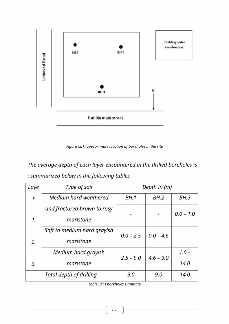
Figure (3:1) show a plan of site and approximate locations of boreholes in the
site .

52
Figure (3:1) approximate location of boreholes in the site
The average depth of each layer encountered in the drilled boreholes is
summarized below in the following tables:
Depth in (m)Type of soilLayer
1.
2.
3.
BH.3BH.2BH.1Medium hard weathered
and fractured brown to rosy
marlstone0.0 – 1.0--
-0.0 – 4.60.0 – 2.5Soft to medium hard grayish
marlstone
1.0 – 14.04.6 – 9.02.5 – 9.0Medium hard grayish marlstone
14.09.09.0Total depth of drillingTable (3:1) boreholes summary

53
Plasticity
Index (PI)
Liquid
limit (%)
% passing
sieve #200
Moisture
Content
(%)
Depth
(m)Borehole
No.
13.2742.468.38.50.00 – 2.51
14.3644.366.510.92.5 - 9.0
14.8347.652.512.10.0 – 4.62
11.3442.859.612.84.6 – 9.0
8.7925.643.87.90.0 – 1.03
12.1643.163.710.91.0 – 14.0Table (3:2) Summary of test results
Angle of internal
Friction Ф(ο)
Cohesion
(Kg/cm2)
Elevation
(m)
Borehole
No.
26310.51
24281.02
28200.53Table (3:3) Summary of shear test results
From the soil report:
Bearing capacity range from 2.75 – 3.83 (Kg/cm2).
In the case of raft foundation, the recommended bearing capacity is 3.0
Kg/cm2.
In the case of isolated footing, the recommended bearing capacity is 2.8
Kg/cm2.
γο : unit weight of soil above foundation level in KN\m3.

54
γο = 18 KN\m3
γ1 : unit weight of soil below foundation level in KN\m3.
γ1 = 18 KN\m3.
C = 29 KN\m2
3:3:2 )Water level:
Ground water was not encountered within the depths of the drilled
boreholes, and no fixed ground water table was observed. No cavities or other
kinds of weaknesses were observed within the depths of the borings.
3:3:3) Settlement Analysis:
The settlement of the foundations designed as described above, and
considering the fact that they will rest on a layer of properly compacted
marlstone, is negligible.
The detailed soil report is attached in the appendices.
55
Chapter Four
Design of Foundation
4:1) Structural Analysis
Columns loads calculated using hand calculations (Tributary area) and these
values checked by program “SAP2000” , where the structure subjected to the
following loads :
1) Dead Load (own weight).
2) Super imposed dead load =250kg/m2.
3) Live loads =250kg/m2.
Using ACI code [5] , the ultimate loads calculated using the following
combinations:
1) Pu =1.4Dead.
2) Pu =1.2Dead + 1.6Live.
Using in this project the following materials characteristics:
f’c =240kg/cm2 ( B 300 )
where : f’c is the compressive strength of concrete
fy = 4200 kg/cm2
where :fy is the yield strength of steel
The following table summarizes loads on columns :

56
colum
n #Dead Load live Load 1.2D+1.6L 1.4D
Service
Load
max
ultimate
1 196 17.5 263 274 214 274
2 294 42 420 412 336 420
3 255.5 30.1 355 358 286 358
4 155.4 11.9 206 218 167 218
5 119 10.5 160 167 130 167
6 203 43.4 313 284 246 313
7 322 72.1 502 451 394 502
8 266 33.6 373 372 300 373
9 315 39.9 442 392 320 400
10 154 29.4 232 216 183 232
11 154 32.9 237 216 187 237
12 91 9.8 125 127 101 127
13 91 5.6 118 127 97 127
14 77 5.6 101 108 83 108
15 70 7.0 95 98 77 98
16 154 19.6 216 216 174 216
17 112 14 157 157 126 157
18 154 16.38 211 216 170 216
19 91 18.2 138 127 109 138
20 301 25.9 403 382 310 398
21 105 8.4 139 147 113 147Table (4:1 ) service loads and ultimate loads
4:2 )Design of single footing
4:2:1 )Determine area of footing

57
Soil report recommended using single footing, so the initial design based on
single footing, and adjustments provided when necessary.
The allowable bearing capacity of the soil equal to 2.8 kg/cm2 (28 ton/m2)
which will be use to determine the required footings’ area, and to complete
other calculations.
Required area = Service load/qu ………..… equ(4:1)
Required area = area which allowable for settlement …..…….….equ(4:2)
Net qu = qu - γ* Df ……..……..equ(4:3)
Where:
γ: soil unit weight
Df: Depth of footing
Net qu = 26.5 ton\m2
Assumed depth =1.5m
There for required area and initial dimensions will be shown next table:
Footingservice
loadRequired area
B Lprovide
areaF1 214 8.1 2.8 3.0 8.4
F2 336 12.7 3.7 3.7 13.69
F3 286 10.8 3.0 3.6 10.8
F4 167 6.3 2.5 2.5 6.25
F5 130 4.9 2.3 2.3 5.3
F6 246 9.3 3.0 3.4 10.2
F7 394 14.9 4.0 4.0 16.0

58
F8 300 11.3 3.5 3.5 12.25
F9 320 12.1 3.5 3.5 12.25
F10 183 6.9 2.7 2.7 7.29
F11 187 7.1 2.7 2.7 7.29
F12 101 3.8 2.0 2.0 4.0
F13 97 3.7 2.0 2.0 4.0
F14 83 3.1 1.8 1.8 3.24
F15 77 2.9 1.8 1.8 3.24
F16 174 6.6 2.7 2.7 7.29
F17 126 4.8 2.3 2.3 5.3
F18 170 6.4 2.2 3.0 6.6
F19 109 4.1 2.3 2.3 5.3
F20 310 11.7 3.5 3.5 12.25
F21 113 4.3 2.3 2.3 5.3Table (4:2) Required area & Initial dimensions
4:2:2 )Elastic Settlements :
Settlement calculations essential to check if the settlement of the footing
with initial dimensions is acceptable.
Se = q0*α *B'* (1-μs2)/Es *Is *If ……………. equ(4:4)
Where : q0 : Net applied pressure at foundation level (KN/m2)
α : = 4 for center , = 1 for corner
B' : = (B/2) for center , = B for corner
μs : Soil poisson ratio .

59
Es : Average modules of elasticity of soil
Is : shape factor
Is = F1 + ( (1-2µs)/(1-µs) )*F2 ............… equ(4:5)
F1 & F2 = f( m' , n' )
m' = (L/B) for center and corner
n' = H/(B/2) for center , = (H/B) for corner
If : Depth factor , = f( (Df/B) , μs , (L/B) )
Note: f1 ,f2 & If from “Principle of Foundation Engineering 5th edition”[1].
Footing 1:
Se = q0*α *B'* (1-μs2)/Es *Is *If
q0 = (214*9.81) / (2.8*3) =249.9 KN/m2
α: = 4 for center
=1.4 B’: = (B/2) for center
μs: = 0.3
KN/m2 Es = 25 *103
Is : shape factor
F1 & F2 = 0.487 , 0.025 respectively
m' = 1.1 , n' = 7 ( assume” initially” depth=1.5m)
Therefore :
Is = 0.487 + ( (1- 2*0.3)/(1-0.3) )*0.025 = 0.5
If = f( (Df/B) , μs , (L/B) ) = 0.733
And , Se = .00197 * 1000 = 19.7 mm
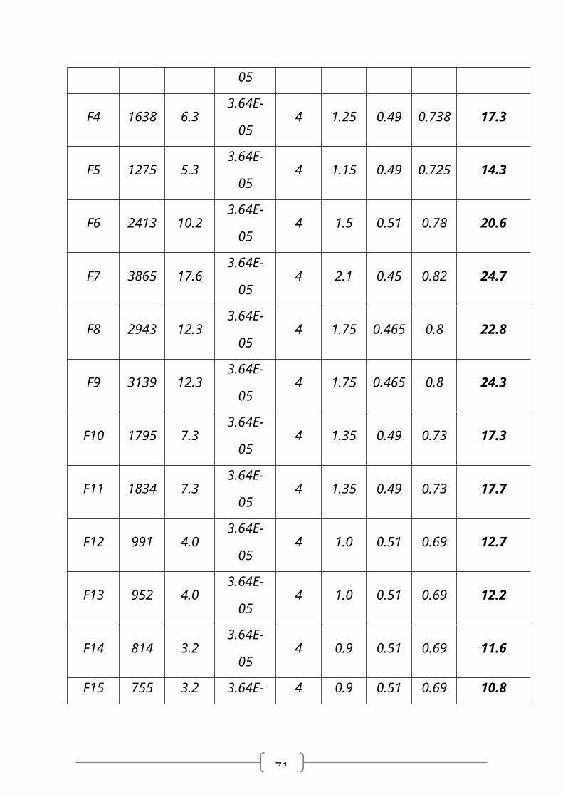
Summary of elastic settlement for all footings will be shown in table (4:3):
Footing
load (KN)
Area (m2)
(1-μs2)/Es α B/2 Is If
Settlement (mm)
F1 2099 8.4 3.64E-05 4 1.4 0.5 0.773 19.7
F2 3296 14.4 3.64E-05 4 1.9 0.47 0.808 24.0

60
F3 2806 10.8 3.64E-05 4 1.5 0.51 0.773 22.4
F4 1638 6.3 3.64E-05 4 1.25 0.49 0.738 17.3
F5 1275 5.3 3.64E-05 4 1.15 0.49 0.725 14.3
F6 2413 10.2 3.64E-05 4 1.5 0.51 0.78 20.6
F7 3865 17.6 3.64E-05 4 2.1 0.45 0.82 24.7
F8 2943 12.3 3.64E-05 4 1.75 0.465 0.8 22.8
F9 3139 12.3 3.64E-05 4 1.75 0.465 0.8 24.3
F10 1795 7.3 3.64E-05 4 1.35 0.49 0.73 17.3
F11 1834 7.3 3.64E-05 4 1.35 0.49 0.73 17.7
F12 991 4.0 3.64E-05 4 1.0 0.51 0.69 12.7
F13 952 4.0 3.64E-05 4 1.0 0.51 0.69 12.2
F14 814 3.2 3.64E-05 4 0.9 0.51 0.69 11.6
F15 755 3.2 3.64E-05 4 0.9 0.51 0.69 10.8
F16 1707 7.3 3.64E-05 4 1.35 0.49 0.73 16.5
F17 1236 5.3 3.64E-05 4 1.15 0.5 0.72 14.1
F18 1668 6.6 3.64E-05 4 1.1 0.49 0.73 14.5
F19 1069 5.3 3.64E-05 4 1.15 0.5 0.72 12.2
F20 3041 12.3 3.64E-05 4 1.75 0.465 0.8 23.5
F21 1109 5.3 3.64E-05 4 1.15 0.5 0.72 12.6Table (4:3) summary of elastic settlement
Note: Footing number 2 ,7 enlarged in order to get acceptable value for
settlement.
Table (4:4) show acceptable value of settlement [1](Recommendation of
European committee):
61
Differential
settlement (mm)
Settlement
)mm(Footing
1925Isolated footing
1950MAT (Raft)
Table (4:4) acceptable value for settlement
Table (4:5) show dimensions of footing to get acceptable pressure on soil and
allowable settlement:
Footing
Required area
B Lprovide
area1 8.1 2.8 3.0 8.4
2 12.7 3.8 3.8 14.44
3 10.8 3.0 3.6 10.8
4 6.3 2.5 2.5 6.25
5 4.9 2.3 3.3 7.59
6 9.3 3.0 3.4 10.2
7 14.9 4.2 4.2 17.64
8 11.3 3.5 3.5 12.25
9 12.1 3.5 3.5 12.25
10 6.9 2.7 2.7 7.29
11 7.1 2.7 2.7 7.29
12 3.8 2.0 2.0 4
13 3.7 2.0 2.0 4
14 3.1 1.8 1.8 3.24
15 2.9 1.8 1.8 3.24
16 6.6 2.7 2.7 7.29
17 4.8 2.3 2.3 5.29
18 6.4 2.2 3.0 6.6

62
19 4.1 2.3 2.3 5.29
20 11.7 3.5 3.5 12.25
21 4.3 2.3 2.3 5.29
Table (4:5) Dimensions of footing for appropriate settlement &pressure
Settlement calculations carried out based on settlement of center of footing
which more than settlement of corner , in addition to calculate settlement as a
flexible footing , but if the footing is rigid , the settlement value will be reduce.
All values of settlement less than 25 mm and no differential settlement more
than 19 mm.
4:2:3 )Thickness of single footing
Depth of footing will be controlled by wide beam shear (one way action)
and punching shear (two way action ).
Wide beam shear:

63
Shear cracks are form at distance “d” from the face of column, and extend to
the compression zone , the compression zone will be fails due to combination
of compression and shear stress.
Max shear will be occurs at distance "d" from face of the column , where "d"
is the effective depth of footing and the shear represented by this formula :
Vu = qu * L ………....equ(4 :6)
Where:
Vu : max shear.
qu= ultimate load /area of footing. ....………..equ(4:7)
Ultimate capacity by concrete given by this formula:
Φ *Vc = 0.75 * 0.53√f'c *B*d *10 ….....……equ(4:8)
Where :
Φ: Safety reduction factor = 0.75 for shear.
f'c : Compressive strength of concrete (cylinder)(Kg\cm2).
B: Footing width.
D: Footing depth.
Φ *Vc > Vu ………..….equ(4:9)
Punching shear:
Formation of inclined cracks around the perimeter of the concentrated load
may cause failure of footing.
Max. shear will be given in this formula:
Vu = qu (B*L – ( (b+d)*(h+d) ) …………..equ(4 :10)
Where:
Vu: Max punching shear.

64
B: Footing width.
L: Footing length.
b:Column width.
h:Column depth.
d:Footing depth.
Concrete shear strength is the smallest of:
Φ*Vc = Φ/6 (1+(2/βc)√f'c*bo*d ………….equ(4:11)
Φ*Vc = Φ/12 ( 2+(αs/(bo/d)) )√f'c*bo*d ………….equ(4:12)
Φ*Vc = Φ (0.33)√f'c*bo*d ………….equ(4:13)
Units in N & mm
Where:
b0 : Perimeter of the critical section taken at " d/2 " from the face of column.
βc: Ratio of longer length to the shorter length of the loaded member (column).
αs : = 40 (Interior footing ).
= 30) Edge footing.(
= 20) Corner footing.(
Note:
For βc <=2 & (b0/d) <=20
Critical:
Φ*Vc = Φ (0.34)√f'c*bo*d ...………….equ(4:14)
Thickness of F1:
F'c = 240 Kg /cm2 ( B300)

65
Fy = 4200 Kg /cm2
The design based on 1 meter
Service load = 214 ton , Ultimate load =274 ton
Area = 2.8 *3 = 8.4 m2
Wide beam shear:
qu= 274/8.4 = 32.6 ton /m2
Vu = 32.6 * (1.25-d)
Φ *Vc = 0.75 * 0.53√240 *1.0 * d *10
Φ *Vc >= Vu from that d=43 cm
Punching shear:
Start with d >43 ( start with “ d “ = 53 cm )
b0 = 432 cm
Vu = 32.6 (2.8*3 – ( (0.3+0.53)*(0.8+0.53) ) =238 ton
Concrete shear strength is the smallest of:
Φ*Vc = 0.75/6 (1+(2/(80/30))√24 *4320*540 /(1000*9.81) =252t
Φ*Vc = 0.75/12 ( 2+(40/(432/53)) )√24*4320*530/(1000*9.81) =498 t
Φ*Vc = 0.75 (0.33)√24*4320*530 /(1000*9.81) =285 t
so , Φ*Vc = 252 t OK
d =53 cm
h = 60 cm
Thickness of F2:
Service load = 336 ton , Ultimate load =420 ton
Area = 3.8 * 3.8 =14.44 m2

66
Wide beam shear:
qu= 420/14.44 = 29.1 ton /m2
Vu = 29.1 * (1.65-d)
Φ *Vc = 0.75 * 0.53√240 *1.0 * d *10
Φ *Vc >= Vu , from that d=53 cm
Punching shear:
Start with d >53 ( start with ' d ' = 63 cm )
b0 = 492 cm
Vu = 29.1(3.8*3.8 – ( (0.4+0.63)*(0.8+0.63) ) =377 ton
For βc <=2 & (b0/d) <=20
Critical:
Φ*Vc = Φ (0.34)√24*4920*630/1000 =3758KN= 394 ton
d =63 cm
h = 70 cm
4:2:4 )Steel Reinforcement (Flexural) :
Isolated footing represented as cantilever, so the max moment occurs at the
face of the column:
Mu = qu *L2 / 2 .….………equ(4:15)
ρ= 0.85 f'c ( 1- (√(1-(2.61*Mu ) ) ) ……………equ(4:16)
fy f'c*b*d2
where :
ρ: Ratio of steel in the section.
Mu : Ultimate moment.

67
F'c : Concrete compressive strength.
Fy : Yield strength of steel.
Minimum ratio of steel is given by :
Ast min = 0.0018 Ag
Where :
Ag : gross section area
Development length:
It is important to check minimum length that the steel must be extended
behind to the point that is not required.
Ld = 0.73 fy db ……….…….equ(4:17) √f'c
Units : N & mm
Where:
Ld: development length in tension
db : diameter of bar
Ldc = 0.24 fy db ……..……….equ(4:18) √f'c
Units : N & mm
Where:
Ldc: development length in compression

68
Load transfer:
It is important to check ability of footing concrete to transfer the load
coming from column.
Pu bearing >= Pu
Where:
Pu: Ultimate load transfer by column
Pu bearing : Ultimate capacity of the footing concrete.
Pu bearing = 0.65 (0.85 fc * Ag(column) ) …………equ(4:19)
If Pu bearing >= Pu , use min dowel reinforcement.
Ast min dowel = 0.005 Ag (column) …………equ(4:20)
Steel reinforcement of F1:
Isolated footing represented as cantilever, so the max moment occurs at the
face of the column:
Mu = 32.6 *1.12 / 2 = 19.7 ton
ρ= 0.85 *240 ( 1- (√(1-(2.61*19.7 *10 5 ) ) ) = .0019 4200 240*100*532
Ast = 0.0019(100)(53) = 10cm2/m
Minimum area of steel is given by :

69
Astmin = 0.0018(100)(60) =10.8cm2/m
So , Ast = 10.8*2.8 = 30.24 cm2
Use 12 Φ 18 (1 Φ18 /22cm c/c) provide 30.6 cm2
In the other direction:
Mu = 25.5 ton
ρ= 0.85 *240 ( 1- (√(1-(2.61*25.5*10 5 ) ) ) =0 .0025 4200 240*100*532
0.0025 * 100 * 53= 13 cm2 /m
Minimum area of steel is given by:
Astmin = 0.0018(100)(60) =10.8cm2/m
So , Ast = 13*3 = 39 cm2
Use 16 Φ 18 (1 Φ18 /18cm c/c) provide 40.8 cm2
Check Development length:
Ld = 0.73 *420*18 = 1130 mm ( for Φ18 mm in tension ) √24Provided = 1550 mm in short direction and 1800 mm in long direction ok

70
Load transfer:
Pu =274 ton
Pu bearing = 0.65 (0.85 *240 * (30*80) )/1000 =318 ton
Pu bearing >= Pu , use min dowel reinforcement.
Ast min dowel = 0.005 (30*80) = 12cm2
Use 4Φ20 provide 12.6 cm2
Ldc = 0.24 *420*20 = 412 mm (for Φ20mm in compression ) √24
>200 mm ( ACI min )
Provided = 530 – 18 = 512 mm ok
Note :For anchoring , a hook can be provided.
Steel reinforcement of F2:
Isolated footing represented as cantilever , so the max moment occurs at the
face of the column:
Mu = 29.1 *1.72 / 2 = 42ton
ρ= 0.85 *240 ( 1- (√(1-(2.61*42 *10 5 ) ) ) = .0029 4200 240*100*632
0.0029 * 100 * 63= 18.2 cm2 /m
Minimum area of steel is given by:
Astmin = 0.0018(100)(70) =12.6cm2/m
71
So , Ast = 18.2*3.8 = 68 cm2
Use 28 Φ 18 (1 Φ18 /13cm c/c) provide 71.4 cm2
In the other direction:
Mu = 32.7 ton
ρ= 0.85 *240 ( 1- (√(1-(2.61*32.7*10 5 ) ) ) =0 .0022 4200 240*100*632
0.0022 * 100 * 63= 14 cm2 /m
Minimum area of steel is given by :
Astmin = 0.0018(100)(70) =12.6cm2/m
So , Ast = 14*3.8 = 53 cm2
Use 21 Φ 18 (1 Φ18 /18cm c/c) provide 53.6 cm2
Check Development length:
Ld = 0.73 *420 *18 = 1130 mm ( for Φ18 mm in tension ) √24
Provided = 2050 in short direction and 2250 in long direction ok
Load transfer:
Pu =420 ton
Pu bearing = 0.65 (0.85 *240 * (40*80) )/1000 =424 ton
Pu bearing >= Pu , use min dowel reinforcement.

72
Ast min dowel = 0.005 (40*80) = 16cm2
Use 6Φ20 provide 18.8cm2
Ldc = 0.24 *4200*20 = 408 mm (for Φ20mm in compression ) √240
>200 mm ( ACI min )
Provided = 630 – 18 = 612 mm ok
Note: For anchoring, a hook can be provided
Results:
1 (Because Footing F5, F6, F12 , F13 overlap each other so , these footing in
addition to the wall footing will be design as a small mat footing as will appear
later.
2 (Footing F10, F17 will design as combined footing.
3 (Footing F11 , F16 will be design as combined footing
4:2:5 )Tie beam design
Tie beams are beams used to connect between columns necks, its function
to provide resistance moments applied on the columns, Tie beams useful in
building that designed to resist earthquakes load to provide limitation of
footings movement, and it’s also important if settlement occurs.
The moment applied on the columns are low , so assuming a tie beam with
dimensions of 30 cm width and 50 cm depth.
b=30 cm

73
d=50cm
Cover=5cm
Steel reinforcement:
Use minimum area of steel:
As min = ρmin b d
ρmin= 14/fy …..………equ(4:21)
ρmin=0.0033
As =0.0033*30*45 =4.46cm2
Use 4 Φ 12 top steel .
Use 4 Φ 12 bottom steel.
Shear reinforcement:
Shear reinforcement provided to avoid shear failure in the beam, where:
3.5bw fy
)Av/S(min = max
0.2 bw√ F ' c ……………equ(4:22) fy
where:
Av : Stirrup area.
S : Spacing between stirrups.

74
)Av/S(min =0.025
Using 10 mm stirrups , So Av=2*0.785 =1.57 cm2
Smin = 63cm.
d/2 =25cm
Maximum spacing = 60 cm
Use 1 Φ 10 / 20cm
4:2:6 )Design a small mat footing:
Small mat is used to connect column 5 , 6 ,12 , 13 in addition to the wall.
Mat thickness controlled by wide beam shear , and punching shear , punching
shear is more critical.
Punching shear given in this equation:
Vu=Pu-qu*d …………………..equ(4:23)
Thickness can be determined by check column with high load and minimum
area.

75
Note : Extension in some edges is carried out in order to reduce punching shear
and therefore reduce thickness of mat.
Check column 5:
Ultimate load =167 ton
Assume d=57cm
Use qu = qall =30ton/m2
Vu=157 – (30*0.57) =151 ton
Φ *Vc = Φ /6 (1+(2/βc)√f'c*bo*d
bo=2540 mm
=0.75/6)1)+2)/80/30√ ((24*2540*570/ 1000=1550KN=158 ton
Φ*Vc = Φ (0.33)√f'c*bo*d
=0.75*0.33√ *24*2540*570/1000= 1756KN=179 ton
OK
Check column 6:
Ultimate load =313 ton
Check d=57cm
Use qu = qall =30ton/m3
Vu=313 – (30*0.57) =297 ton
b0 =4680 mm
Φ*Vc = Φ (0.34)√24*4680*570/1000 =3335KN= 340cton (OK)
Use d=73cm
h=80cm

76
cover = 7 cm
This increase in depth because high bending moment in x-direction at wall.
See figure (4:1) which show the small mat footing
Figure (4:1) small Mat footing
Steel Reinforcement :
Using SAP2000, Bending moment values determined, there for the amount of
required steel is also determined.
The mat divided into strips in order to put the required amount of steel in the
required place instead of providing maximum steel to the whole area.
X-direction:
The area in the x-direction will be divided into 2 sections:
Figure (4:2) show bending moment in x-direction using SAP2000:

77
Figure (4:2) Bending moment in x-direction using SAP2000
Section 1:
Max BM-ve =193t.m
ρ= 0.85 *240 ( 1- (√(1-(2.61*193*10 5 ) ) ) =0.0107 4200 240*100*732
Therefore, Ast =0.0107(100) (73) =78 cm2
Use 11 Φ30/m (Top steel)

78
Minimum bottom steel required
Use 4 Φ25/m (Bottom steel)
Section 2:
Max BM+ve =85t.m
ρ= 0.85 *240 ( 1- (√(1-(2.61*85*10 5 ) ) ) =0.0044 4200 240*100*73
Therefore, Ast =0.0044(100) (73) =32.2cm2
Use 7 Φ25/m (Bottom steel)
Max BM-ve =62 t.m
ρ= 0.85 *240 ( 1- (√(1-(2.61*62*10 5 ) ) ) =0.0032
4200 240*100*732
Therefore, Ast =0.0032(100) (73) =23.2cm2
Use 5 Φ25/m (Top steel)
Y-direction:
The area in the y-direction will be divided into 3 sections:

79
Figure (4:3) show bending moment in y-direction using SAP2000:
Section 1:
Max BM+ve =70 t.m
ρ= 0.85 *240 ( 1- (√(1-(2.61*30*10 5 ) ) ) =0.0036 4200 240*100*732
Therefore, Ast =0.0036(100) (73) =26.3cm2
Use 6Φ25/m (Bottom steel)
Max BM-ve =5 t.m
ρ= 0.85 *240 ( 1- (√(1-(2.61*5*10 5 ) ) ) =<ρmin
80
4200 240*100*732
Ast=0.0018(100)(80) =14.4cm2
Use 4 Φ25/m (Top steel)
Section 2:
Max BM+ve =25 t.m
ρ= 0.85 *240 ( 1- (√(1-(2.61*25*10 5 ) ) ) =<ρmin
4200 240*100*732
Therefore, Ast =0.0018(100) (80) =14.4cm2
Use 4 Φ25/m (Bottom steel)
Max BM-ve =8 t.m
ρ= 0.85 *240 ( 1- (√(1-(2.61*8*10 5 ) ) ) =< ρmin
4200 240*100*732
Therefore, Ast =0.0018(100) (80) =14.4cm2
Use 4Φ25/m (Top steel)
Section 3:
Max BM+ve =95 t.m

81
ρ= 0.85 *240 ( 1- (√(1-(2.61*95*10 5 ) ) ) =0.005
4200 240*100*732
Therefore, Ast =0.005(100) (73) =36.2cm2
Use 8Φ25/m (Bottom steel)
Max BM-ve =25 t.m
ρ= 0.85 *240 ( 1- (√(1-(2.61*25*10 5 ) ) ) =< ρmin
4200 240*100*732
Ast=0.0018(100)(80) =14.4cm2
Use 4 Φ25/m (Top steel)
4:2:7 )Summaries of Dimensions & Reinforcement
The following table shows summary of single footing depth:
Footing B (m) L (m) d (m) h (m)
F1 2.8 3.0 53 60

82
F2 3.8 3.8 63 70
F3 3.0 3.6 58 65
F4 2.5 2.5 43 50
F7 4.2 4.2 71 80
F8 3.5 3.5 58 65
F9 3.5 3.5 71 80
F14 1.8 1.8 38 45
F15 1.8 1.8 38 45
F18 2.2 3.0 53 60
F19 2.3 2.3 43 50
F20 3.5 3.5 71 80
F21 2.3 2.3 43 50Table (4:6) summary of dimensions:
Note:
1 (Provide 10 cm plain concrete under footings .
2 (Other footing will be design as combined footing or as small mat as appear
in the previous section (4:2:6).
The following table shows summary of single footing reinforcement:
FootingReinforcement
in short direction
Reinforcement in long
direction
Dowel reinforcement
F1 16Φ18 12Φ18 4Φ20
F2 28Φ18 21Φ18 6Φ20
F3 19Φ18 19Φ18 6Φ20

83
F4 14Φ18 9Φ18 4Φ20
F7 30Φ18 26Φ18 6Φ25
F8 24Φ18 18Φ18 6Φ20
F9 27Φ18 23Φ18 6Φ20
F14 10Φ14 10Φ14 4Φ14
F15 10Φ14 10Φ14 4Φ14
F18 13Φ18 13Φ18 6Φ20
F19 8Φ18 8Φ18 4Φ20
F20 24Φ18 20Φ18 8Φ25
F21 8Φ18 8Φ18 4Φ20Table (4:7) summary of reinforcement in footing
Summary of small mat reinforcement appear in the following tables:
NotesBottom steelTop steelForm Y1toY2Section
4Φ25/m11 Φ30/m 0 – 1.41
Top steel required 7Φ25/m5Φ25/m1.4 – 4.22

84
under column
Table(4:8) small Mat Reinforcement in x-direction
Where the point (x,y) (0,0) is the edge of column 13
Summary of reinforcement in y-direction shown in the next table:
NotesTop steelBottom steelForm X1toX2Section
Reducing Bottom
steel can be applied
away from columns
4Φ25/m6 Φ25/m 0 – 11
-4Φ25/m4Φ25/m1 – 4.82
Reducing top steel
can be applied away
from columns
4Φ25/m8 Φ25/m 4.8 – 6.43
Table(4:9) Mat Reinforcement in x-direction
Check settlement in small mat:
Form SAP2000 settlement values as in the following table:
Settlement (mm)location
15.7Below column 5
13.3Below column 6
18.1Below wall

85
15.8Below column 12
18.9Below column 13
20.0Max Below cornerTable(4:10) settlement values of the small footing
Settlement values are acceptable
See reinforcement details in appendices (appendix III)
4:3 )Design of combined footing:
Combined footing using when:
1 (There is overlap between footings
2 (There is restriction in area especially for exterior column
Combined footing will be design as a beam in long direction & Isolated footing
in short direction.

86
Thickness of combined footing will be control by:
* Max Bending Moment
* Wide beam shear
* Punching shear
In this project , note that there is overlapping between footing 10,17 & 11,16 ,
so this footing will be design as combined footing.
Footing (10,17) Combined 1:
Table (4:11) show Ultimate & service load on column 10 and 17:
1710Column#
126183Service load
(ton)
157232Ultimate
load (ton)
Table (4:11) Ultimate & service load on column 10 and 17
Area = Total service load \ Allowable bearing capacity …………..equ(4:24)
Area = (183+126) / (26.5) = 11.7 m2
It is important to avoid differential settlement by coincidence center of mass of
footing and center of loads affecting on the footing, so:
X = Q2*L / (Q2+Q1) ……………….equ(4:25)
Where : Q1, Q2 are the service load affecting on column 10 , 17 respectively.
X = (126*1.85)/(126+183) =0.75 m

87
L=2(L2+X) = 4.7 m
Where : L is footing length.
B = 11.7 / 4.7 = 2.5 m2
Where : B is footing width.
Figure (4:4) show Combined footing (1) and its dimensions:
Figure (4:4) combined footing 1
Thickness and reinforcement:
qult= (232+157)/(2.5*4.7) =33.1 ton/m2
Ultimate pressure per meter = 33.1 *2.5 = 82.8 t/m'
From that: see figure (4:5) & (4:6) which represent shear force diagram and
Bending Moment Diagram respectively.

88
Figure (4:5) shear force diagram (ton)
Figure (4:6) Bending moment diagram (ton.m)
Maximum bending moment = 106 ton.m
Mn = Mu/ Φ …………………equ(4:26)
Mn=116 t.m
Assume:
ρ=ρmax / 2
where ρ is the longitudinal ratio of steel.
ρmax = 0.75 (0.85*f'c *β/fy) ( 6100/(6100+fy) ) …………….equ(4:27)
ρmax/2 = 0.75 (0.85*240*0.85/4200) ( 6100/(6100+4200) )/2 = 0.0092
Rn = Mn / (b* d2) …..…………equ(4:28)

89
Rn = 116 / (2.5* d2)
Where:
Mn : Nominal moment.
b :Section width.
d : Section depth.
Rn =ρ* fy ( 1- (ρ*f'c/2) ) (N.mm) ……………….equ(4:29)
Rn =0.0092* 420 ( 1- (0.0092*24/2) ) =3.5N/mm2 =350t/m2
So , d=37 cm
Check shear:
Max shear occurs at distance "d" from face of column:
Φ *Vc = 0.75 * 0.53√f'c *B*d *10
= 0.75*0.53√240* 2.5*d *10 =154d
Ultimate shear at the face of column (from figure (4:5) ) is = 90-82.4d
So , d=38cm
Use d= 38cm
Check punching shear:
Vult =pu - qu*(d+c)(d+b)
Where : c , b is the column depth , width respectively.
qu=232/(2.35*2.5)=39t/m2
Vult = 232 – 39(0.38+0.80)(0.38+0.40)=196ton
For βc <=2 & (b0/d) <=20
Critical:
Φ*Vc = Φ (0.34)√24*3820*380 = 1760 KN=185 ton not good
So ,
Use d= 43cm (provides Φ*Vc =219ton)

90
h=50cm
Reinforcement:
ρnew= ρ= 0.85 *240 ( 1- (√(1-(2.61*116 *10 5 ) ) ) = 0.0072 4200 240*250*432
Ast = 0.0072*250*43 = 77cm2
Use 16 Φ25 (1 Φ25 /15cm c/c)
In the opposite direction, footing considered as isolated footing.
Width = Column width +2*d = 170 cm
qu10=232/(2.5*1.7)=55 ton/m2
Mu10 = 55 *1.7*1.052 / 2 = 52 ton.m
qu17=157/(2.5*1.6)=39ton/m2
Mu17 = 39 *1.6*1.12 / 2 = 38 ton.m
ρ= 0.85 *240 ( 1- (√(1-(2.61*52*10 5 ) ) ) = 0.0046 4200 240*170*432
Ast = 0.0046*170*43=33.6
Use 14 Φ18 (1 Φ18 /12cm c/c)
ρ= 0.85 *240 ( 1- (√(1-(2.61*39*10 5 ) ) ) = 0.0036 4200 240*160*432
Ast = 0.0036(160)(43) =24.8cm2
Use 10 Φ 18 (1 Φ18 /15cm c/c)
Load transfer:

91
Column 10(80*40) carry 424 ton > Pu
Column 17(70*40) carry 371 ton >pu
Use minimum dowel Reinforcement.
Use 6 Φ20
Development length:
Ld = 0.73 fy db (Tension)
√f'c
Ldc = 0.24 fy db (compression)
√f'c
Units : N & mm
Φ14 : required 0.88 m provided = 1.45m (Tension)
Φ18 : required 1.14m provided >1.14m (Tension)
Φ20 : required 0.24 m provided >0.24m (compression)
Footing (11,16) Combined 2:
Table (4:12) show Ultimate & service load on column 11 and 16:
1611Column#
174187Service load
(ton)
216237Ultimate
load (ton)

92
Table (4:12) Ultimate & service load on column 10 and 17
Area = Total service load / Allowable bearing capacity
Area = (187+174) / (26.5) = 13.6 m2
It is important to avoid differential settlement by getting center of mass of
footing is the same as center of loads affecting on the footing, so:
X = Q2*L / (Q2+Q1)
Where : Q1, Q2 are the service load affecting on column 10 , 17 respectively.
X = (174*1.85)/(174+187) =0.89 m
L=2(L2+X) = 5.2 m use 5.2m
Where : L is footing length.
B = 13.6 / 5.2 = 2.61 m use 2.7 m
Where : B is footing width.
Figure (4:7) show combined footing 2 and its dimensions:

93
Figure (4:7) combined footing2
Thickness and reinforcement:
qult = Total ultimate load / Footing area
qult= (237+216)/(2.7*5.2) =32.3 ton/m2
Ultimate pressure per meter = 33.1 *2.7 = 87.2t/m'
From that : see figures (4:8) & (4:9) which represent shear force diagram and
Bending Moment Diagram respectively .
Figure (4:8) shear force diagram (ton)
Figure(4:9) Bending moment diagram (ton.m)
Maximum bending moment = 132 ton.m
Mn = Mu/ Φ

94
Mn=147 t.m
Assume:
ρ=ρmax / 2
where ρ is the longitudinal ratio of steel.
ρmax = 0.75 (0.85*f'c *β/fy) ( 6100/(6100+fy) )
ρmax/2 = 0.75 (0.85*240*0.85/4200) ( 6100/(6100+4200) )/2 = 0.0092
Rn = Mn / (b* d2)
Rn = 147 / (2.7* d2)
Where:
Mn : Nominal moment.
b :Section width.
d : Section depth.
Rn =ρ* fy ( 1- (ρ*f'c/2) ) (N.mm)
Rn =0.0092* 420 ( 1- (0.0092*24/2) ) =3.5N/mm2 =350t/m2
So , d=40 cm
Check shear:
Max shear occurs at distance "d" from face of column:
Φ *Vc = 0.75 * 0.53√f'c *B*d *10
= 0.75*0.53√240 * 2.7*d *10 =166d
Ultimate shear at the face of column (from fig.(4:8) )is = 113.4- 87.3d
So , d=45cm
Check punching shear:
Vult =pu - qu*(d+c)(d+b)
Where: c , b is the column depth , width respectively.

95
qu=237/(2.7*2.6)=33t/m2
Vult = 237 – 33(0.45+0.7)(0.45+0.3)=209ton
For βc <=2 & (b0/d) <=20
Critical:
Φ*Vc = Φ (0.34)√24*4000*450 = 2180 KN=222 ton
ok
Use d= 45cm
h=50cm
Reinforcement:
ρnew= ρ= 0.85 *240 ( 1- (√(1-(2.61*147 *10 5 ) ) ) = 0.0077 4200 240*270*452
Ast = 0.0077*270*45 = 93.7cm2
Use 20Φ25 (1 Φ25 /13cm c/c)
In the opposite direction , footing considered as isolated footing.
Width = Column width +2*d =170 cm
qu11=237/(2.7*1.7)=52 ton/m2
Mu11 = 52*1.152 / 2 = 34.4 ton.m
qu16=216/(2.7*1.6)=50ton/m2
Mu16 = 50 *1.152 / 2 = 33 ton.m
ρ= 0.85 *240 ( 1- (√(1-(2.61*34.4*10 5 ) ) ) = 0.0027 4200 240*170*452
Ast=0.0027*45*170=20.8 cm2
Use 9 Φ 18 (1 Φ18 /18cm c/c)

96
Load transfer:
Column 11(80*30) carry 318 ton > Pu
Column 17(70*30) carry 278 ton >pu
Use minimum dowel Reinforcement.
Use 4 Φ20
Development length :
Ld = 0.73 fy db (Tension) √f'c
Ldc = 0.24 fy db (compression) √f'c
Units : N & mm
Φ14 : required 0.88 m provided = 1.45m (Tension)
Φ18 : required 1.14m provided >1.14m (Tension)
Φ20 : required 0.24 m provided >0.24m (compression)

97
See Combined footing reinforcement details in appendices
4:4 )Design of wall footing:
Shear walls which using in project supported by wall footing, this wall footing
carried a distributed load (load per meter) , so the design of wall footing will be
per meter.
The design steps are the same as design of single footing, but thickness will be
controlled by wide-beam shear.
The first wall footing designed as a part of the small mat and the second wall
which lies between column14 &15.
Ultimate load /m' = 55t/m' (From SAP2000)
Service load /m' = 45t/m' (from SAP2000)
Wall width = service load /allowable bearing capacity

98
B = 45 /26.5 = 1.7 m
Use B=1.8 m
check shear:
qu = 55/1.7 = 32.4 t/m2
Vu = qu * L
= 32.4) 0.75– d(
Φ *Vc = 0.75 * 0.53√240 *d *10
From that : d= 26cm
Use the same depth of footing:
Use d=35cm
h =40cm
Steel reinforcement:
Max moment in wall footing occurs at in the middle between center line of wall
and face of wall
So , BM = qu*L2/2
BM = 32.4 (0.82)/2 =10.4ton.m
ρ= 0.85 *240 ( 1- (√(1-(2.61*10.4*10 5 ) ) ) = 0.0029>ρmin
4200 240*170*352
Ast =0.0029 * 100*35 = 8cm2/m
Ast total =8*4.4 = 35.2cm2
Use 23 Φ14 (1 Φ18 /18cm c/c)

99
In the other direction use min area of steel
Astmin = 0.0018(170)(40) =12.24cm2
Use 8 Φ14 (1 Φ18 /20cm c/c)
Development length:
Φ14 : required 0.88 m provided = 1.0 m (Tension)
4:5 )Mat or Raft foundations
4:5:1 )Design of raft or mat foundation
Mat foundation is one footing usually placed under the entire building area ,
they are used when the soil bearing capacity is low or\and columns loads are
heavy , and it can be used to reduce settlement .
In this section, design of footing will be as a one footing support all columns as
an alternative of design.
Note: Pressure under mat foundation (q) especially under corner columns <qall
q= P +_ Mxx*Y +_ Myy*X …..……..equ(4:30) A Ixx Iyy
Where :

100
P: Total Column LoadsA: total mat areaMxx & Ixx: Moment & moment of inertia about x-axis respectivelyMyy & Iyy: Moment & moment of inertia about y-axis respectively
Mat thickness controlled by wide beam shear, and punching shear , punching
shear is more critical.
Concrete capacity for shear given in this equation:
Vu=Pu-qu*d ………..equ(4:31)
Thickness can be determined by check column with high load and minimum
area.
Check column 7:
Ultimate load =502 ton
Assume d=80cm
Use qu = qall =30ton/2
Vu=502 – (30*0.8) =478 ton
Φ*Vc = Φ (0.34)√24*6000*800/1000 =6100KN= 622 ton (OK)
Check column 8:
Ultimate load =373 ton
Check d=80cm
Use qu = qall =30ton/m2
Vu=373 – (30*0.8) =349 ton
Φ*Vc = Φ (0.34)√24*3600*800/1000 =3600KN= 367 ton (OK)
Check column 9:

101
Ultimate load =400 ton
Check d=80cm
Use qu = qall =30ton/m2
Vu=400 – (30*0.8) =376 ton
Φ*Vc = Φ/6 (1+(2/βc)√f'c*bo*d
=0.75/6)1)+2)/80/30√ ((24*3000*800= 262 ton Not OK
Φ*Vc = Φ/12 ( 2+(αs/(bo/d)) )√f'c*bo*d
Φ*Vc = Φ (0.33)√f'c*bo*d
increase d=100cm
Vu=370 ton
Φ*Vc=371 ton (OK)
Check Column 2:
d=100cm
Ultimate load =420 ton
Φ*Vc=510 ton (OK)
Vu= 420-(30*1)=390ton
Check Column 20:
Ultimate load =400 ton
Use qu = qall =30ton/m2
Vu=400 – (30*1) =370 ton
Φ*Vc = Φ/6 (1+(2/βc)√f'c*bo*d
=0.75/6)1)+2)/70/30√ ((24*3700*1000= 429 ton OK
Φ*Vc = Φ/12 ( 2+(αs/(bo/d)) )√f'c*bo*d
Φ*Vc = Φ (0.33)√f'c*bo*d

102
=0.75)0.33√( (24*3700*1000/1000=4486KN=457ton
Use d=100cm
h=110cm
Cover = 10cm
Note: Extension in some corners is carried out in order to reduce punching
shear and therefore reduce thickness of mat.
See figure (4:10) which show mat foundation in the project:
Figure (4:10) Mat foundation

103
Steel Reinforcement :
Using SAP2000, Bending moment values determined, there for the amount of
required steel is also determined.
The mat divided into strips in order to put the required amount of steel in the
required place instead of providing maximum steel to the whole area.
X-direction:
The area in the x-direction will be divided into 6 sections:
Figure (4:11) show bending moment in x-direction using SAP2000:

104
Figure (4:11) BM in x-direction of mat foundation using SAP2000
Section 1:
Max BM+ve =160t.m
ρ= 0.85 *240 ( 1- (√(1-(2.61*160*10 5 ) ) ) =0.00442 4200 240*100*1002
Therefore, Ast =0.00442(100) (100) =44 cm2
Use 9 Φ25/m (bottom steel)
Max BM-ve =50t.m
ρ= 0.85 *240 ( 1- (√(1-(2.61*50*10 5 ) ) ) < ρmin
4200 240*100*1002
Use minimum area of steel:
Astmin=0.0018(100)(110) =19.8cm2
Use 5 Φ25/m (Top steel)
Section 6:
Max BM+ve =130t.m
ρ= 0.85 *240 ( 1- (√(1-(2.61*130*10 5 ) ) ) =0.0036 4200 240*100*1002
Therefore, Ast =0.0036(100) (100) =36cm2
Use 8 Φ25/m (Bottom steel)

105
Max BM-ve =120 t.m
ρ= 0.85 *240 ( 1- (√(1-(2.61*120*10 5 ) ) ) =0.0033 4200 240*100*1002
Therefore, Ast =0.0033(100) (100) =33cm2
Use 7Φ25/m (Top steel)
Summary of reinforcement in x-direction shown in the following table:
NotesTop steelBottom steelForm Y1toY2Section
Bottom steel required
under columns &
between columns.
Top steel can be
reduced as span length
reduce as appear in
BM diagram
5 Φ25/m 9Φ25/m0 – 1
1
5 Φ25/m 5 Φ25/m 1 - 5.5
2
6 Φ25/m 6 Φ25/m 5.5 – 10
3
6Φ25/m6 Φ25/m 10 – 15
4
7 Φ25/m 5 Φ25/m 15 – 18
5
7 Φ25/m 8 Φ25/m 18 - 19.85
6
Table(4:13) Mat Reinforcement in x-direction
Note: The Point (X,Y) = (0,0) is considered as the exterior edge of column21

106
Y-direction:
The area in the y-direction will be divided into 6 sections:
Figure (4:12) show bending moment in y-direction using SAP2000:
Figure (4:12) BM in y-direction of mat foundation using SAP2000
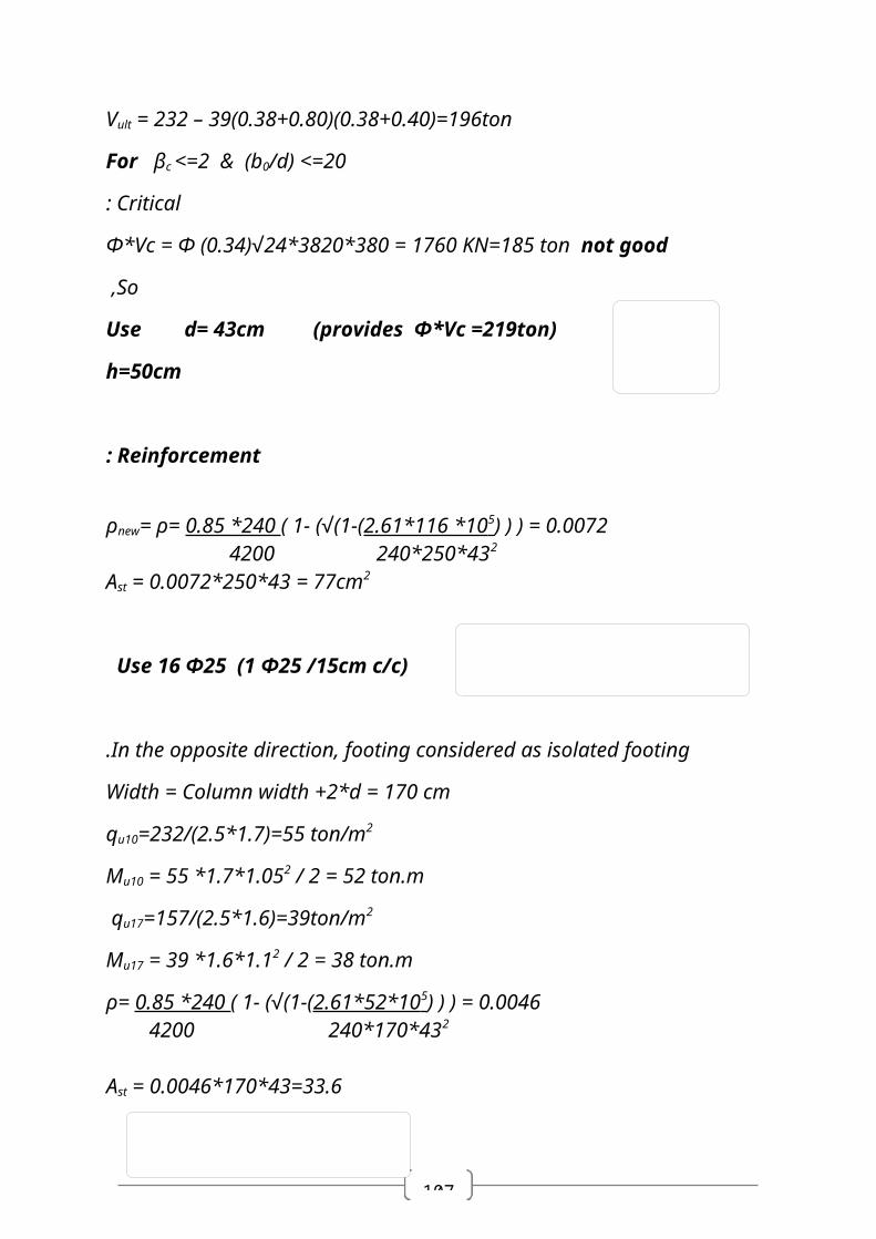
107
Section 1:
Max BM+ve =15t.m
ρ= 0.85 *240 ( 1- (√(1-(2.61*15*10 5 ) ) ) =< ρmin
4200 240*100*1002
Therefore, Ast =0.0018(100) (110) =19.8cm2
Use 5Φ25/m (Bottom steel)
Max BM-ve =85t.m
ρ= 0.85 *240 ( 1- (√(1-(2.61*85*10 5 ) ) ) =0.0023 4200 240*100*1002
Ast=0.0023(100)(100) =23cm2
Use 5 Φ25/m (Top steel)
Section 6:
Max BM+ve =135t.m
ρ= 0.85 *240 ( 1- (√(1-(2.61*135*10 5 ) ) ) =0.00371 4200 240*100*1002
Therefore, Ast =0.00371(100) (100) =37.1cm2
Use 8 Φ25/m (Bottom steel)
Max BM-ve =83 t.m

108
ρ= 0.85 *240 ( 1- (√(1-(2.61*83*10 5 ) ) ) =0.00224 4200 240*100*1002
Therefore, Ast =0.00224(100) (100) =22.4cm2
Use 5 Φ25/m (Top steel)
Summary of reinforcement in Y-direction shown in the following table:
NotesTop steelBottom SteelForm X1toX2Section
Bottom steel required
under columns
(except column 19) &
between columns.
Top steel can be
reduced as span
length reduce as
appear in BM
diagram
5 Φ25/m 5 Φ25/m 0 – 6
1
5 Φ25/m 5 Φ25/m 6 – 10
2
5 Φ25/m 5 Φ25/m 10 – 13
3
5 Φ25/m 5 Φ25/m 13 – 17.5
4
5Φ25/m5 Φ25/m 17.5 – 21
5
6 Φ25/m 8 Φ25/m 21 – 23.8
6
Table(4:14) Mat Reinforcement in Y-direction
Note: The Point (X,Y) = (0,0) is considered as the exterior edge of column21

109
4:5:2 )Settlement of mat foundation
Form SAP2000, settlement values as following:
Settlement (mm)Location
12.8Below column 1
12.6Below column 4
6.5Below column 2
3.7Below column 7
12.4Below column 21
7.0Below column 9Table(4:15) settlement values of the mat foundation
Settlement values are acceptable.
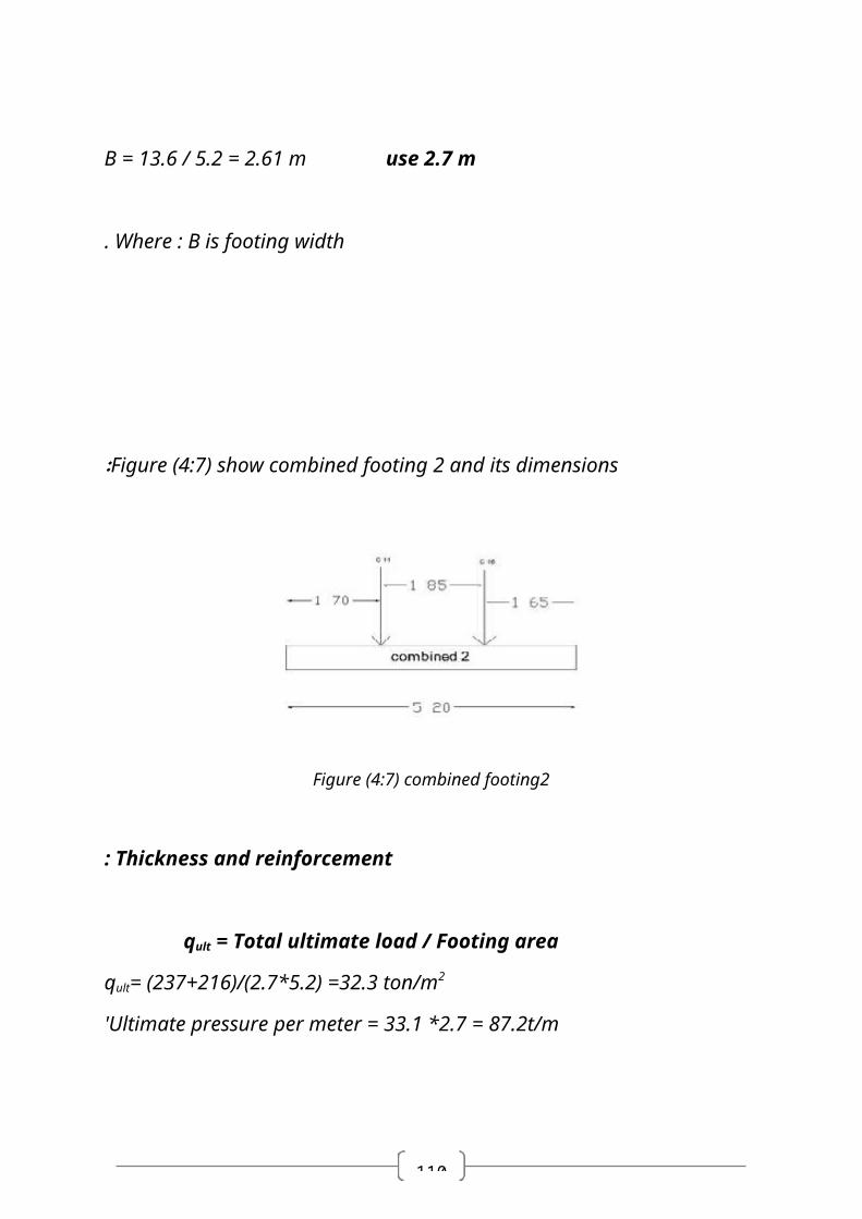
110
Appendices

111
GEOTECHNICALSITE INVESTIGATION
REPORT
MR. BASHAR AL SAIFI MULTI-STORY BUILDING
(RAFIDIA - NABLUS)
(Basin # 11/Rafidia, Plot # 5/11)
Prepared for:Consulting Engineering Office - Nablus
Prepared by:Hijjawi Construction Labs

112
August – 2007
Messrs. Bashar Al Saifi Ref : SI/202Nablus Date : 30/8/2007C/O Consulting Engineering Office
Project - Proposed Seven Story Building in Nablus – RafidiaSubject - Geotechnical Investigation Report
Dear Sirs,
With reference to your request (SI/202) of 25/8/2007, Hijjawi Construction Labs is pleased to submit this report of the geotechnical site investigation carried out for the proposed construction site of the above cited project.
The investigation ended up with conclusions and recommendations relevant to the findings. Those, in addition to the laboratory test results and engineering recommendations are herewith attached.
We Look forward for further cooperation and would like to take this opportunity to highly considerate your confidence in our laboratories. For any clarification concerning this report, please contact us at your convenience.
Yours sincerely,

113
Dr. Sami A. HijjawiGeneral Manager
CONTENTS
1. INTRODUCTION
1.
1
GENERAL
1.
2
PROJECT DESCRIPTION
1.
3
PURPOSE AND SCOPE
2. SITE CONDITIONS
2.
1
DESCRIPTION
2.
2
SUBSURFACE CONDITIONS –
TOPOGRAPHY AND GENERAL GEOLOGY2.
3
GROUND WATER
3. FIELD EXPLORATION AND SAMPLING
3.
1
DRILLING

114
3.
2
SAMPLING
4. LABORATORY TESTING
4.
1
TESTS CARRIED OUT
4.
2
SUMMARY OF LABORATORY TEST RESULTS
5. BEARING CAPACITY ANALYSIS
6. SELECTION OF FOUNDATION TYPE
7. SETTLEMENT ANALYSIS
8. ENGINEERING RECOMMENDATIONS
9. REFERENCES
1
0.
APPENDIX
1. INTRODUCTION
1.1 GENERAL
This report presents the outcome of the site investigation carried out for the proposed construction site of a new multi - story building in Rafidia area (Nablus) (Basin # 11/ Rafidia, Plot # 5/11).
1.2 PROJECT DESCRIPTION
The project consists of the construction of an eight story building with plan area of about 350 square meters.

115
1.3 PURPOSE AND SCOPE
Investigation of the underground conditions at a site is prerequisite to the economical design of the substructure elements. It is also necessary to obtain sufficient information for feasibility and economic studies for any project.
It should be also noted that the scarcity of construction sites in the urban areas of the West Bank with considerable urban renewal and the accompanying backfill, often with no quality control, affects the underground conditions and results significant variation within a few meters in any direction.
In general, the purpose of this site investigation was to provide the following:
1- Information to determine the type of foundation required (shallow or deep).
4- Information to allow the geotechnical consultant to make a recommendation on the allowable bearing capacity of the soil.
5- Sufficient data/ laboratory tests to make settlement and swelling predictions.4- Location of the groundwater level.
5- Information so that the identification and solution of excavation problems can be made.
6- Information regarding permeability and compaction properties of the encountered materials.
This was accomplished through the close cooperation of HCL's geotechnical engineer and the technical staff of its Geotechnical Department.
2. SITE CONDITIONS

116
2.1 DESCRIPTION
The project site lies the south of Rafidia main street in Nablus. It is bordered by an unpaved street from the east and an existing building from the west as shown on the attached plan-layout.
No high voltage, electrical or telephone poles, sewer or water pipes were observed within the depths of the drilled boreholes.
A general site plan showing the locations of boreholes is presented in Fig.1.
2.2SUBSURFACE CONDITIONS –
TOPOGRAPHY AND GENERAL GEOLOGY
The studied construction area is approximately flat (after its excavation and preparation for construction). The general soil formation within the depths of the borings consists mostly of medium hard to soft, grayish formation of marlstone. In borehole No.3, the marlstone formation was overlaid by a thin layer of medium hard weathered formation of light brown to rosy, fractured marlstone with boulders.The average depth of each layer encountered in the drilled boreholes is summarized below:
No. of layer
Type of soilDepth in (m)
BH.1 BH.2 BH.3
1.
Medium hard weathered and
fractured brown to rosy marlstone
- - 0.0-1.0
2.Soft to medium
hard grayish marlstone
0.0-2.5 0.0-4.6 -

117
3.Medium hard
grayish marlstone2.5-9.0 4.6-9.0
1.0-14.0
Total depth of drilling 9.0 9.0 14.0
The drilled boreholes for this study reflect the described above general conditions and are enough, in our opinion, to represent the whole area of the proposed construction. They are discussed in more detail in subsequent sections of this report. Borehole logs with detailed subsurface description are attached.
2.3 GROUNDWATER AND CAVITIES
Ground water was not encountered within the depths of the drilled boreholes, and no fixed ground water table was observed. No cavities or other kinds of weaknesses were observed within the depths of the borings.
3. FIELD EXPLORATION AND TESTING
3.1 DRILLING
The geotechnical investigation program agreed upon with the Client to explore the subsurface conditions in accordance with the Jordanian Code for Site Investigations included the drilling of three boreholes within the boundaries of the site: two to a depth of 9m each and one to a depth of 14m from the existing ground level on the date of boring.

118
The drilling was carried out utilizing a truck - mounted drilling rig type Mobile Drill – Model B-31.
Representative soil samples were placed in sealed plastic bags and transported to the laboratory for further testing.
The locations of the drilled boreholes are shown in Fig.1. The borehole logs are attached.
3.2 SAMPLING
Due to the nature of the encountered soils and the fracturing of the encountered marlstone, mostly within the whole depth of drilling, it was difficult to obtain undisturbed samples. As a practically acceptable solution, disturbed samples suitable for identification and index property testing purposes were sampled at various depths. Samples required for strength tests were remolded in laboratory conditions.
Representative samples were placed in sealed plastic bags and transported to the laboratory for further testing.
In our opinion the obtained samples were of good quality

119
BH.1
BH.2
BH.3
Unpaved
road
Building under
construct-ion
Rafidia main street
N
Fig. 1 Approximate locations of boreholes (drawn not to scale)
4 . LABORATORY TESTING
Representative soil samples were collected from the drilled boreholes, tightly sealed and transported to HCL's Laboratories in Nablus.
4.1 TESTS CARRIED OUT

120
The following tests were performed to evaluate the engineering properties of the soils influencing the performance of the proposed structures:
1- Natural moisture contents were determined in accordance with BS 1377 (Test No.1).
2- Grain size distribution (sieve analysis) in accordance with BS 1377 (Test No. 7A). Standard sieves were used to perform the sieve analysis tests on material after washing on sieve No.200.
3- Atterberg limits (Liquid and Plastic) in accordance with BS 1377 (Test No. 2 & 3). Liquid and plastic limits tests were conducted on soil samples and the plasticity index (PI) was determined.
4- Direct shear test in accordance with ASTM D-3080, where three identical specimens were sheared under three vertical load conditions and the maximum shear stress in each case was measured. The strength parameters, namely cohesion (c) and angle of internal friction (Ø) were determined from the maximum shear-vs- normal stress plot.
The results of the mentioned above tests are summarized in tables below:
BoreholeNo.
Depth(m)
Moisture
content (%)
% Passin
g sieve #200
Liquid limit(%)
Plasticity
Index(PI)
1 0.0-2.5 8.5 68.3 42.4 13.22.5-9.0 10.9 66.5 44.3 14.3
2 0.0-4.6 12.1 52.5 47.6 14.84.6-9.0 12.8 59.6 42.8 11.3
3 0.0-1.0 7.9 43.8 25.6 8.71.0-14.0 10.9 63.7 43.1 12.1
Table (1) Summary of Test Results

121
Borehole No.
Elevation (m)
Cohesion(Kg/cm²)
Angle of internal
friction f (°)1 0.5 31 262 1.0 28 243 0.5 20 28
*Samples were collected from the cuttings resulted from drilling.
Table (2) Summary of Shear Test Result
5 . BEARING CAPACITY ANALYSIS
The bearing capacity was calculated using the shear test parameters of cohesion and angle of internal friction and the soil density of the specimens extracted from the boreholes, the following well known Terzaghi equation with correction terms suggested by Schultze can be used to calculate the bearing capacity of rectangular foundation of any sides ratio B:L
qult = (1+ 0.3 B/L) CNc + go DNq + (1- 0.2 B/L) (g1B/2) Ng
where:go - Unit weight of soil above foundation level in KN/m³.g1 - Unit weight of soil below foundation level in KN/m³.
C,Ø - Strength parameters of the soil below foundation level in KN/m² and
degrees
respectively.
B - Width of foundation in (m).
L - Length of foundation in (m).

122
Nc, Nq, Ng - Bearing capacity coefficients dependent on the angle of internal
friction
of the soil below foundation level (dimensionless).
D - Depth of foundation (m).
Calculations for an assumed isolated footing :
Considering:B = 2.5 mL = 2.5 mD = 0.5 mgo= 18 KN/m³
g1 = 18 KN/m³ C = 29 KN/m²
Ø = 24 º and reducing C and Ø according to Terzaghi to C' = 2/3 C = 19 KN/m²
tan Ø' = 2/3 tan Ø, ® Ø' = 16º
The bearing capacity was computed using a special computer program following both
Terzaghi and Vesic methods. The sheet with computations is attached. Based on the
calculations, a bearing capacity range of 2.75 -3.83 Kg/cm2 is given by the twomethods at an average depth of 5m from the original ground (before excavation)assuming isolated footings will be utilized. In case of raft foundation, thebearing capacity is 3.0 kg/cm2. These bearing values were calculated assuming
that the site will be properly drained and that the water regime will be properlycontrolled.
6 . SELECTION OF FOUNDATION TYPE

123
According to the nature and characteristics of the materials encountered in the drilled boreholes (medium hard marlstone), we suggest to consider isolated footings on the marlstone formation with bearing capacity = 2.8 kg/cm2 at any depth from the existing on the date of excavation level after removing of all loose inclusions from the surface (foundation level).
7 . SETTLEMENT ANALYSIS
The settlement of the foundations designed as described above, and considering
the fact that they will rest on a layer of properly compacted marlstone, is
negligible.
8. ENGINEERING RECOMMENDATIONS
As a result of field and laboratory activities carried out and the analysis of the available data and test results, the following engineering
recommendations can be made:
8.1 TYPE AND DEPTH OF FOUNDATIONS
Owing to the encountered subsurface conditions, which are discussed in this
report, it is recommended to consider isolated footings with tie beams at
any depth from the existing on the date of excavation ground. The
recommended bearing capacity at the foundation level is 2.8 kg/cm2.
8.2 MATERIALS FOR BACKFILLING - COMPACTION CRITERIA

124
The materials encountered in the drilled boreholes are satisfactory for using for
backfilling purposes. In general, materials for the backfilling should be granular,
not containing rocks or lumps over 15 cm in greatest dimension, free from
organic matter, with plasticity index (PI) not more than 20. The backfill material
should be laid in lifts not exceeding 25 cm in loose thickness and compacted to
at least 95 percent of the maximum dry density at optimum moisture content as
determined by modified compaction tests (Proctor) (ASTM D-698).
8.3 DRAINAGE OF THE SITE
It is recommended to design an effective rainwater drainage system to get rid of the consequences of the rainwater percolation into the layers. The site should be graded so as to direct rainwater and water away from all planned structures.
8.4 SEISMIC CONSIDERATIONS
As far as the seismic activity in the region has not witnessed any serious
earthquakes in the last 70 years, the last series of earthquakes since February
2004 in Palestine and neighboring Middle East countries and their serious
consequences made it necessary to consider a seismic precautive factor in the
design of the project structures.
Referring to the Unified Building Code Research in Jordan, the area can be
considered within Zone B, which corresponds to an intensity of VI to VIII
according to the Mercalli Scale (4-6 Richter Scale respectively).

125
According to the seismic zoning chart prepared by An-Najah National University
for Palestine (see appendix), the seismic gravity acceleration factor for area
(Zone IV)
z = 0.24-0.25 g , where g – gravity acceleration.
Finally , it should be noted that the results and recommendations of this
report are solely based on the collected samples from the drilled boreholes
25/8/2007 and assuming that the subsurface conditions do not significantly
deviate from those disclosed in the borehole logs.
9 . REFERENCES
األولى، الطبعة عمان، واالسكان، العامة األشغال وزارة. الموقع استطالع كودة-1
1990.
واالسكان، العامة األشغال وزارة. الساندة والجدران واألساسات القواعد كودة-2
.1992 األولى، الطبعة عمان،3- Code of practice for Site Investigations. BS 5930: 1981. British Standards
Institution.
4- Methods of Test for Soils for Civil Engineering Purposes. BS 1377:
1975. British Standards Institution.
5- K.H. Head. Manual of Soil Laboratory Testing. Vol. 1 & 2. ELE
International Ltd. London, 1984.

126
6- J.E. Bowles. Foundation Analysis and Design. Third edition. McGraw - Hill
International, 1982.
7- M.J. Tomlinson. Foundation Design and Construction. Fourth edition,
ELBS, London, 1983.
8- R.Peck, W.Hanson, T.Thornburn. Foundation Engineering. 2nd edition,
Willey, 1980.
9- N. Tsytovich. Soil Mechanics. Mir Publishers. Moscow, 1987.
10-N. Maslov. Basic Engineering Geology and Soil Mechanics. Mir Publishers.
Moscow, 1987.
10-Proceedings of the Seminar On Clay Soil In Jordan. Royal Scientific Society
and British Research Establishment. Amman, 1983

127
References
1) Das, Braja, (2004), ‘Principles of Foundation Engineering, (Fifth
edition), Thomson.
2) Das, Braja, ‘Principles of Geotechnical Engineering’ (Student edition), Thomson.
3) Boarman, R. (2001), ‘Foundation Design and Construction’.

128
4) M.J. Tomlinson ‘Foundation Design and Construction’ (Fourth edition), ELBS, London, 1983.
5) ACI 318-02.
6) Charles G. Salmon & Chu-Kia Wang. (1998), ‘Reinforced Concrete Design ‘ ,California (sixth edition).
.2001, الأولى الطبعة ,سوريه ,والعلوم للنشر شعاع ,الأساسات هندسة)7