Embed Size (px)
Citation preview
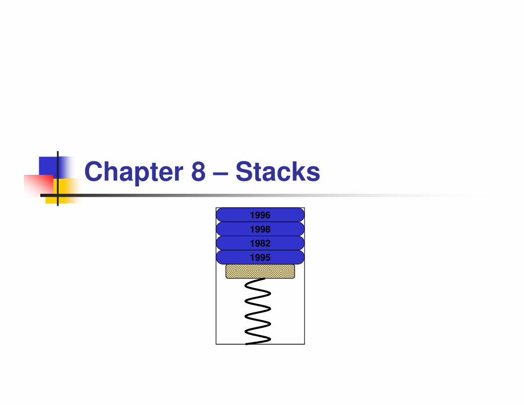
Chapter 8 – Stacks
1996
1998
1982
1995

BYU CS/ECEn 124 Chapter 8 - Stacks 2
Topics to Cover…
� The Stack
� Subroutines
� Subroutine Linkage
� Saving Registers
� Stack Operations
� Activation Records� Example 8.1: Activation Records
� Recursive Subroutines
� Interrupt Stack Usage
BYU CS/ECEn 124 Chapter 8 - Stacks 3
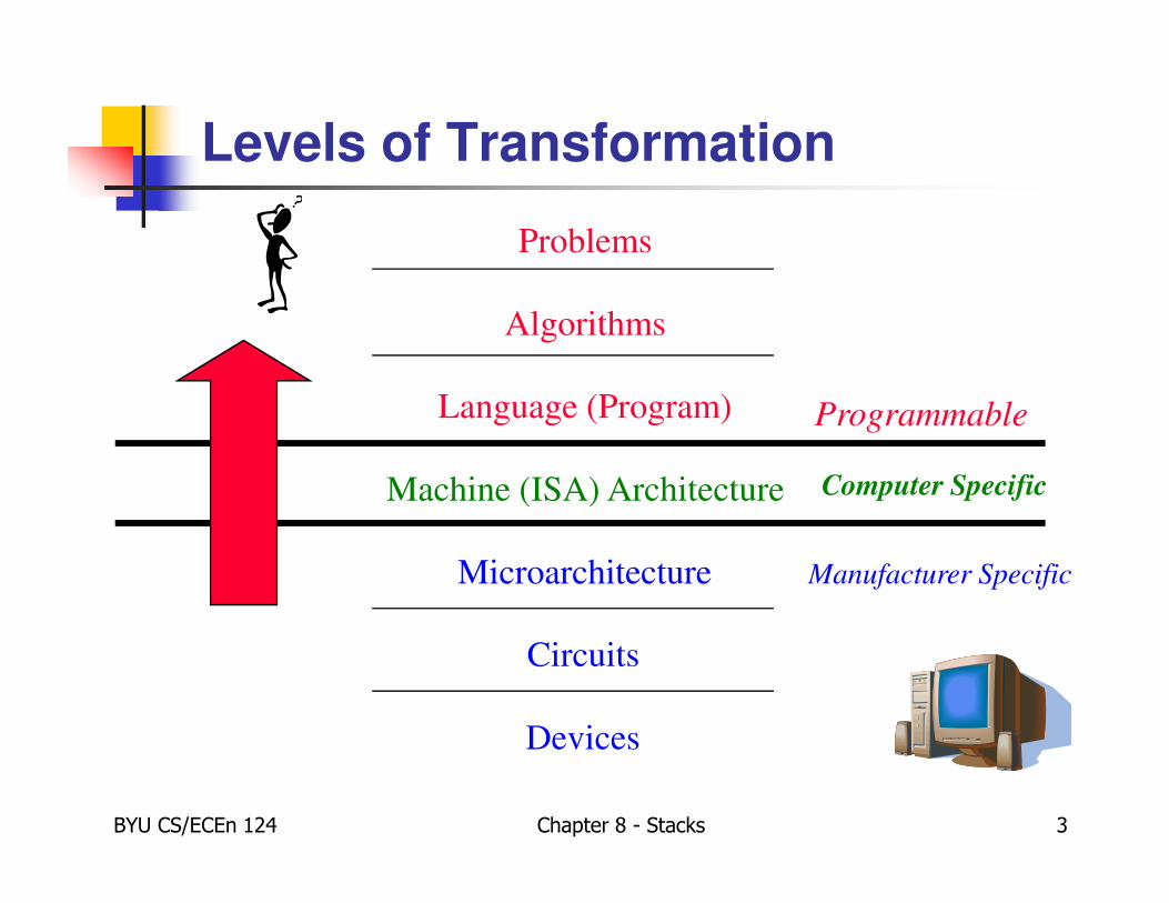
Levels of Transformation
Problems
Algorithms
Language (Program)
Machine (ISA) Architecture
Microarchitecture
Circuits
Devices
Programmable
Computer Specific
Manufacturer Specific
BYU CS/ECEn 124 Chapter 8 - Stacks 4
Stacks
� Stacks are the fundamental data structure of
computers today.
� A stack is a Last In, First Out (LIFO) abstract data
structure.
� A true stack is a restricted data structure with two
fundamental operations, namely push and pop.
� Elements are removed from a stack in the reverse
order of their addition.
� Memory stacks are used for random access of
local variables.
The Stack
BYU CS/ECEn 124 Chapter 8 - Stacks 5
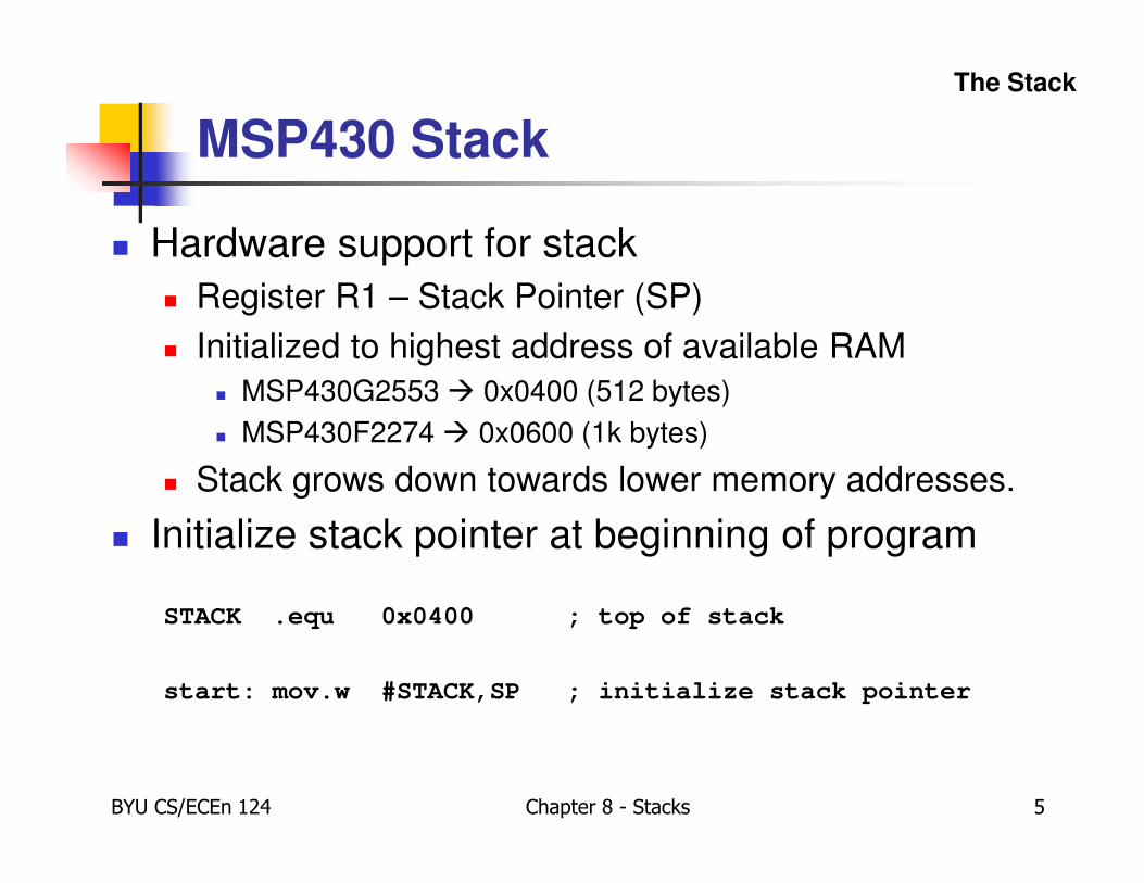
MSP430 Stack
� Hardware support for stack
� Register R1 – Stack Pointer (SP)
� Initialized to highest address of available RAM
� MSP430G2553 � 0x0400 (512 bytes)
� MSP430F2274 � 0x0600 (1k bytes)
� Stack grows down towards lower memory addresses.
� Initialize stack pointer at beginning of program
STACK .equ 0x0400 ; top of stack
start: mov.w #STACK,SP ; initialize stack pointer
The Stack
BYU CS/ECEn 124 Chapter 8 - Stacks 6
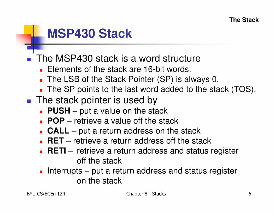
MSP430 Stack
� The MSP430 stack is a word structure� Elements of the stack are 16-bit words.
� The LSB of the Stack Pointer (SP) is always 0.
� The SP points to the last word added to the stack (TOS).
� The stack pointer is used by� PUSH – put a value on the stack
� POP – retrieve a value off the stack
� CALL – put a return address on the stack
� RET – retrieve a return address off the stack
� RETI – retrieve a return address and status register
off the stack
� Interrupts – put a return address and status register
on the stack
The Stack
BYU CS/ECEn 124 Chapter 8 - Stacks 7
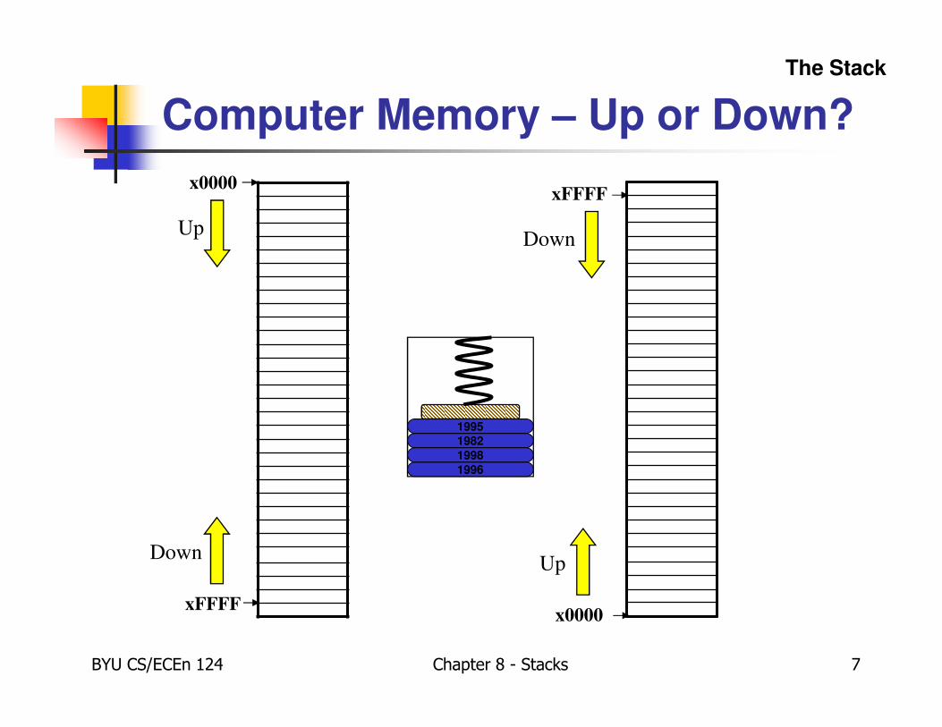
Computer Memory – Up or Down?
x0000
xFFFF
Up
Down
xFFFF
x0000
Down
Up
The Stack
1996
1998
19821995
BYU CS/ECEn 124 Chapter 8 - Stacks 8
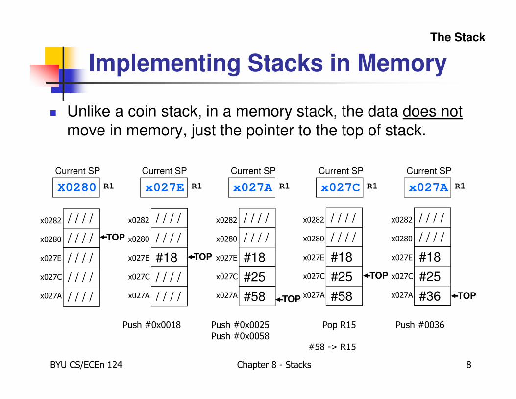
Implementing Stacks in Memory
� Unlike a coin stack, in a memory stack, the data does not
move in memory, just the pointer to the top of stack.
/ / / /
/ / / /
/ / / /
/ / / /
/ / / /
TOP
Current SP
X0280 R1
x0282
x0280
x027E
x027C
x027A
/ / / /
/ / / /
#18
/ / / /
/ / / /
TOP
x0282
x0280
x027E
x027C
x027A
Current SP
x027E R1
Push #0x0018
/ / / /
/ / / /
#18
#25
#58
TOP
x0282
x0280
x027E
x027C
x027A
Current SP
x027C R1
Pop R15
#58 -> R15
/ / / /
/ / / /
#18
#25
#58 TOP
x0282
x0280
x027E
x027C
x027A
Current SP
x027A R1
Push #0x0025Push #0x0058
/ / / /
/ / / /
#18
#25
#36 TOP
x0282
x0280
x027E
x027C
x027A
Current SP
x027A R1
Push #0036
The Stack
BYU CS/ECEn 124 Chapter 8 - Stacks 9
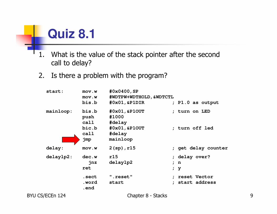
Quiz 8.1
1. What is the value of the stack pointer after the second call to delay?
2. Is there a problem with the program?
start: mov.w #0x0400,SP
mov.w #WDTPW+WDTHOLD,&WDTCTL
bis.b #0x01,&P1DIR ; P1.0 as output
mainloop: bis.b #0x01,&P1OUT ; turn on LED
push #1000
call #delay
bic.b #0x01,&P1OUT ; turn off led
call #delay
jmp mainloop
delay: mov.w 2(sp),r15 ; get delay counter
delaylp2: dec.w r15 ; delay over?
jnz delaylp2 ; n
ret ; y
.sect ".reset" ; reset Vector
.word start ; start address
.end
BYU CS/ECEn 124 Chapter 8 - Stacks 10
Subroutines
� A subroutine is a program fragment that performs some useful function.� Subroutines help to organize a program.
� Subroutines should have strong cohesion – perform only one specific task.
� Subroutines should be loosely coupled – interfaced only through parameters (where possible) and be independent of the remaining code.
� Subroutines keep the program smaller� Smaller programs are easier to maintain.
� Reduces development costs while increasing reliability.
� Fewer bugs – copying code repeats bugs.
� Subroutines are often collected into libraries.
Subroutines
BYU CS/ECEn 124 Chapter 8 - Stacks 11
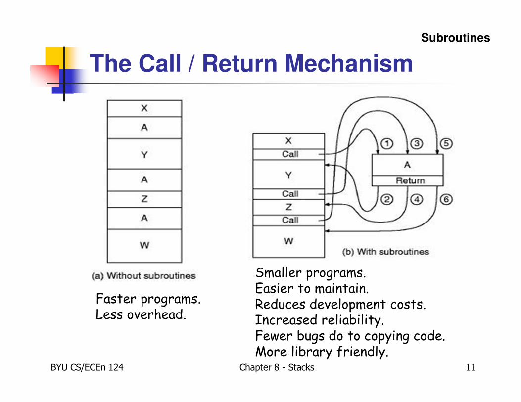
The Call / Return Mechanism
Subroutines
Smaller programs.Easier to maintain.Reduces development costs.Increased reliability.Fewer bugs do to copying code.More library friendly.
Faster programs.Less overhead.
BYU CS/ECEn 124 Chapter 8 - Stacks 12
Subroutine Linkage
� A subroutine is “called” in assembly using the MSP430
CALL instruction.
� The address of the next instruction after the subroutine call
is saved by the processor on the stack.
� Parameters are passed to the subroutine in registers
and/or on the stack.
� Local variables are created on the stack at the beginning
of the subroutine and popped from the stack just before
returning from the subroutine.
� At the end of a subroutine, a RET instruction “pops” the top
value from the stack into the program counter.
Subroutine Linkage

BYU CS/ECEn 124 Chapter 8 - Stacks 13
Stack Operations
� Single operand instructions:
� Emulated instructions:
Mnemonic Operation Description
PUSH(.B or .W) src SP-2→→→→SP, src→→→→@SP Push byte/word source on stack
CALL dst dst→→→→tmp ,SP-2→→→→SP,PC→→→→@SP, tmp→→→→PC
Subroutine call to destination
RETI TOS→→→→SR, SP+2→→→→SPTOS→→→→PC, SP+2→→→→SP
Return from interrupt
Mnemonic Operation Emulation Description
RET @SP→→→→PCSP+2→→→→SP
MOV @SP+,PC Return from subroutine
POP(.B or .W) dst @SP→→→→tempSP+2→→→→SPtemp→→→→dst
MOV(.B or .W) @SP+,dst Pop byte/word from stack to destination
Subroutine Linkage
func
Memory
BYU CS/ECEn 124 Chapter 8 - Stacks 14
Call
Registers
CPU
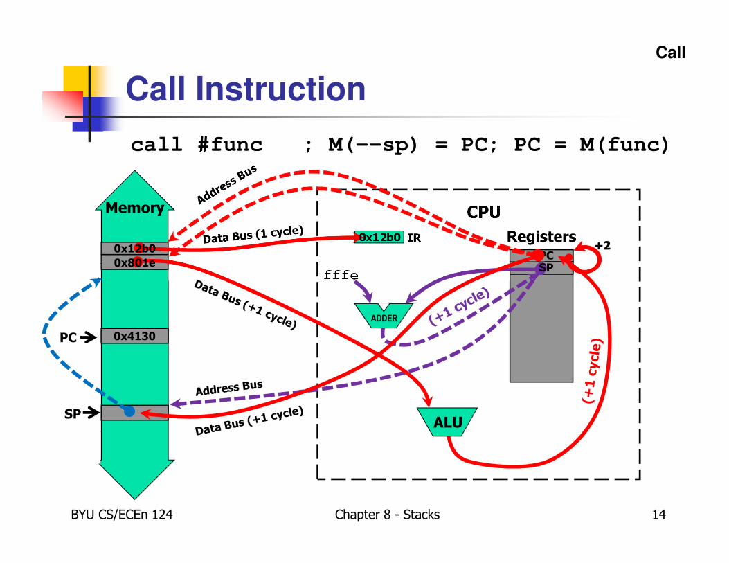
Call Instruction
call #func ; M(--sp) = PC; PC = M(func)
PCPCPC
IR0x12b00x12b0
fffe
SP
SP
0x4130PC
ALU
ADDER
PCSP0x801e
+2+2
BYU CS/ECEn 124 Chapter 8 - Stacks 15
Subroutine Call
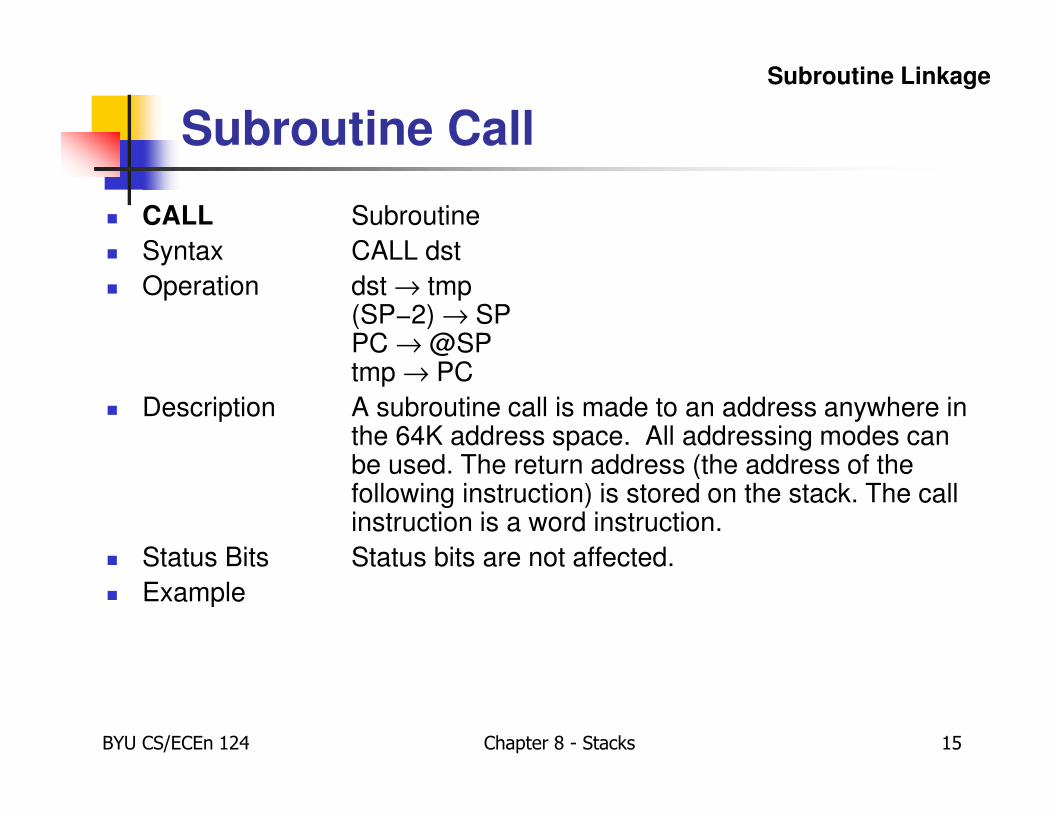
� CALL Subroutine
� Syntax CALL dst
� Operation dst → tmp(SP−2) → SPPC → @SPtmp → PC
� Description A subroutine call is made to an address anywhere in the 64K address space. All addressing modes can be used. The return address (the address of the following instruction) is stored on the stack. The call instruction is a word instruction.
� Status Bits Status bits are not affected.
� Example
Subroutine Linkage
BYU CS/ECEn 124 Chapter 8 - Stacks 16
CALL Examples
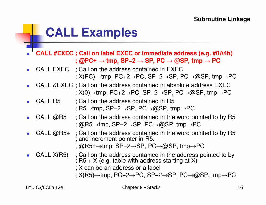
� CALL #EXEC ; Call on label EXEC or immediate address (e.g. #0A4h); @PC+ → tmp, SP−2 → SP, PC → @SP, tmp → PC
� CALL EXEC ; Call on the address contained in EXEC
; X(PC)→tmp, PC+2→PC, SP−2→SP, PC→@SP, tmp→PC
� CALL &EXEC ; Call on the address contained in absolute address EXEC
; X(0)→tmp, PC+2→PC, SP−2→SP, PC→@SP, tmp→PC
� CALL R5 ; Call on the address contained in R5
; R5→tmp, SP−2→SP, PC→@SP, tmp→PC
� CALL @R5 ; Call on the address contained in the word pointed to by R5
; @R5→tmp, SP−2→SP, PC→@SP, tmp→PC
� CALL @R5+ ; Call on the address contained in the word pointed to by R5 ; and increment pointer in R5.
; @R5+→tmp, SP−2→SP, PC→@SP, tmp→PC
� CALL X(R5) ; Call on the address contained in the address pointed to by ; R5 + X (e.g. table with address starting at X)
; X can be an address or a label
; X(R5)→tmp, PC+2→PC, SP−2→SP, PC→@SP, tmp→PC
Subroutine Linkage

BYU CS/ECEn 124 Chapter 8 - Stacks 17
Caution…
� The destination of branches and calls is used indirectly, and this means the content of the destination is used as the address.
� Errors occur often when confusing symbolic and absolute modes:� CALL MAIN ; Subroutine’s address is stored in MAIN
� CALL #MAIN ; Subroutine starts at address MAIN
� The real behavior is easily seen when looking to the branch instruction. It is an emulated instruction using the MOV instruction:� BR MAIN ; Emulated instruction BR
� MOV MAIN,PC ; Emulation by MOV instruction
� The addressing for the CALL instruction is exactly the same as for the BR instruction.
Subroutine Linkage
Memory
BYU CS/ECEn 124 Chapter 8 - Stacks 18
Return
Registers
ALU
CPU
ADDER
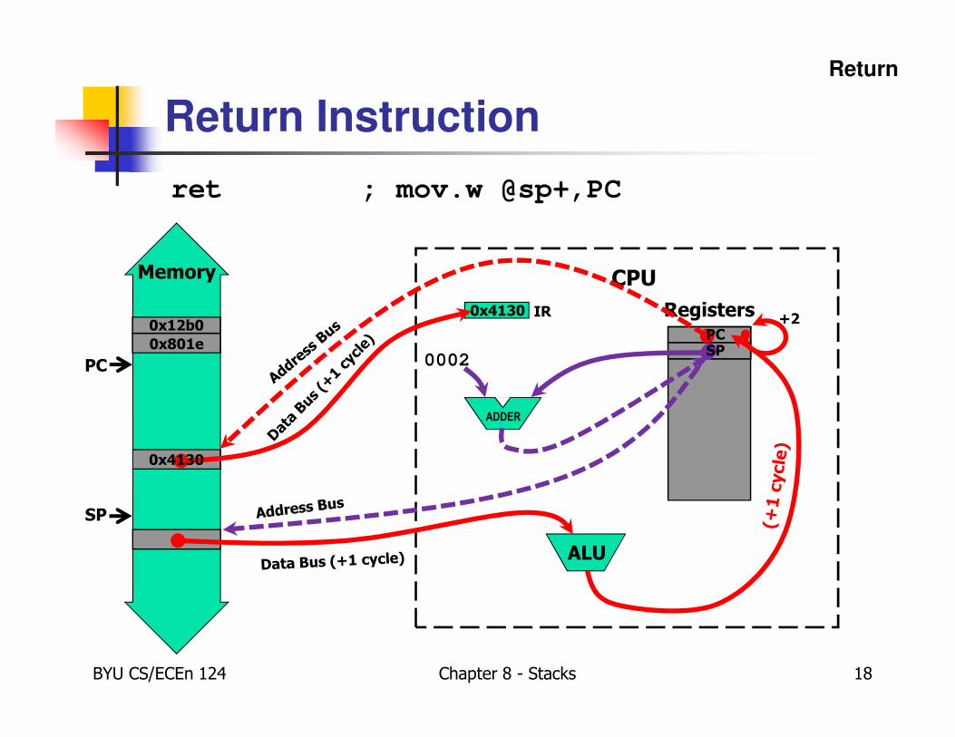
Return Instruction
ret ; mov.w @sp+,PC
0x801e
PC
IR0x12b0
0002
SP
0x4130
0x4130PCPC
PC
SPSP
PCSPPC
+2

BYU CS/ECEn 124 Chapter 8 - Stacks 19
Return from Subroutine
� RET Return from subroutine
� Syntax RET
� Operation @SP→ PCSP + 2 → SP
� Emulation MOV @SP+,PC
� Description The return address pushed onto the stack by a CALL instruction is moved to the program counter. The program continues at the code address following the subroutine call.
� Status Bits Status bits are not affected.
� Example
Subroutine Linkage
BYU CS/ECEn 124 Chapter 8 - Stacks 20
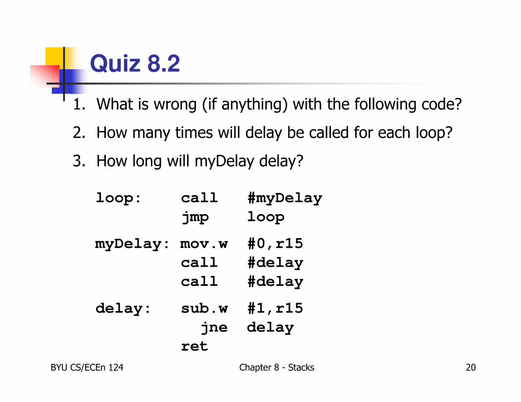
Quiz 8.2
1. What is wrong (if anything) with the following code?
2. How many times will delay be called for each loop?
3. How long will myDelay delay?
loop: call #myDelay
jmp loop
myDelay: mov.w #0,r15
call #delay
call #delay
delay: sub.w #1,r15
jne delay
ret
BYU CS/ECEn 124 Chapter 8 - Stacks 21
Saving and Restoring Registers
� Called routine -- “callee-save”
� At beginning of subroutine, save all registers that will be altered (unless a register is used to return a value to the calling program or is a scratch register!)
� Before returning, restore saved registers in reverse order.
� Or, avoid using registers altogether.
� Calling routine -- “caller-save”
� If registers need to be preserved across subroutine calls, the calling program would save those registers before calling routine and restore upon returning from routine.
� Obviously, avoiding the use of registers altogether would be considered caller-safe.
� Values are saved by storing them in memory, preferably on the stack.
Saving Registers
BYU CS/ECEn 124 Chapter 8 - Stacks 22
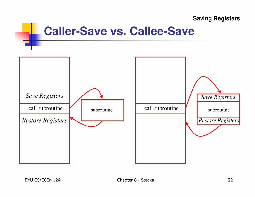
Caller-Save vs. Callee-Save
call subroutine
Save Registers
subroutine
Restore Registers
call subroutine subroutine
Save Registers
Restore Registers
Saving Registers
BYU CS/ECEn 124 Chapter 8 - Stacks 23
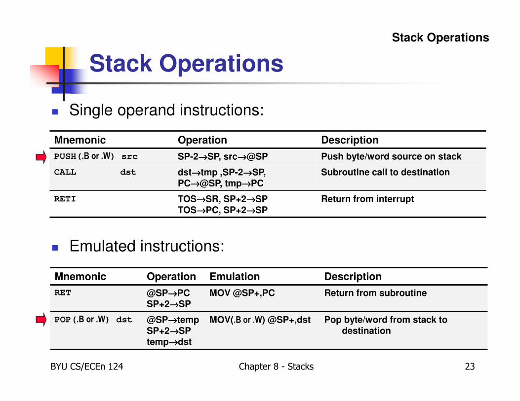
Stack Operations
� Single operand instructions:
� Emulated instructions:
Mnemonic Operation Description
PUSH(.B or .W) src SP-2→→→→SP, src→→→→@SP Push byte/word source on stack
CALL dst dst→→→→tmp ,SP-2→→→→SP,PC→→→→@SP, tmp→→→→PC
Subroutine call to destination
RETI TOS→→→→SR, SP+2→→→→SPTOS→→→→PC, SP+2→→→→SP
Return from interrupt
Mnemonic Operation Emulation Description
RET @SP→→→→PCSP+2→→→→SP
MOV @SP+,PC Return from subroutine
POP(.B or .W) dst @SP→→→→tempSP+2→→→→SPtemp→→→→dst
MOV(.B or .W) @SP+,dst Pop byte/word from stack to destination
Stack Operations
Memory
BYU CS/ECEn 124 Chapter 8 - Stacks 24
Push
Registers
Data Bus (+1 cycle)
CPU
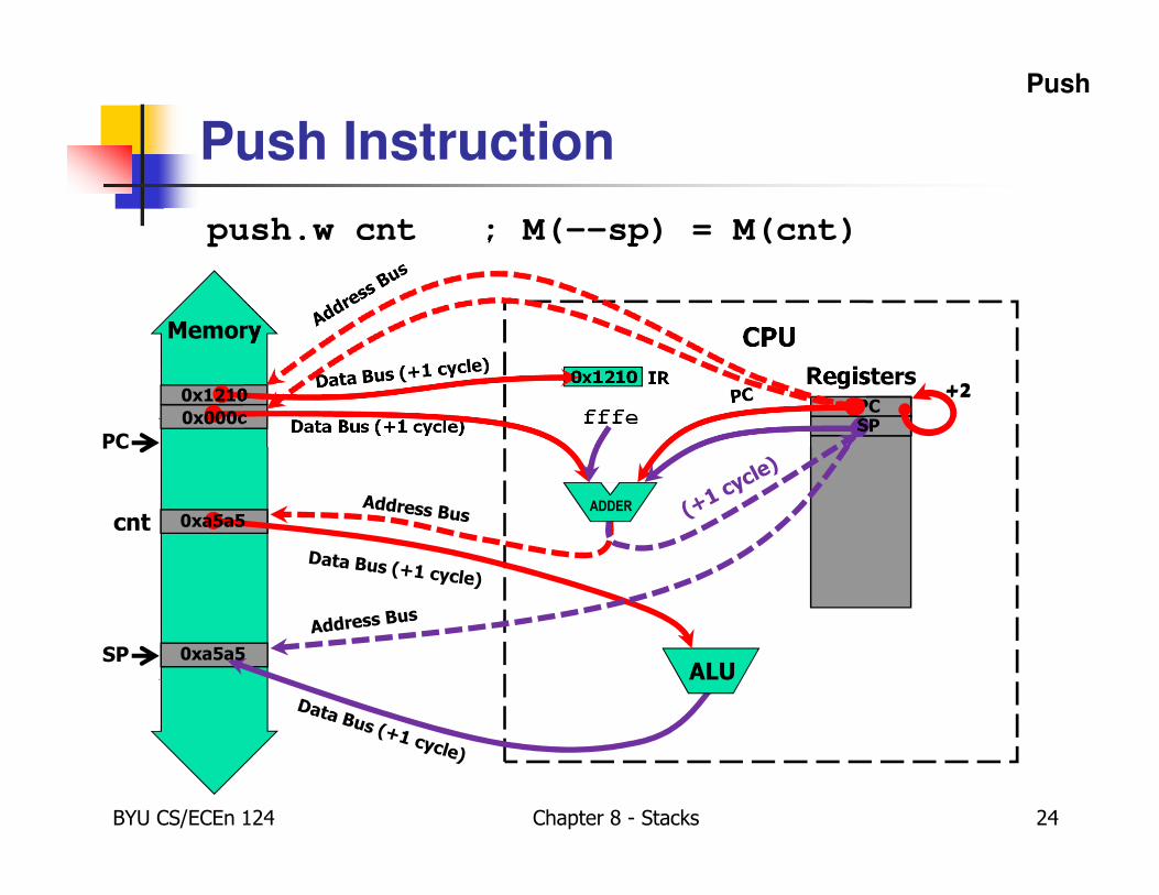
Push Instruction
cnt
push.w cnt ; M(--sp) = M(cnt)
0x000c
PCPCPC
IR0x12100x1210
PCfffe
SPSP
0xa5a5
0xa5a5ALU
ADDER
SP
+2+2

BYU CS/ECEn 124 Chapter 8 - Stacks 25
Push Operand
� PUSH Push word or byte onto stack
� Syntax PUSH{.W or .B} src
� Operation SP − 2 → SPsrc → @SP
� Description The stack pointer is decremented by two, then the source operand is moved to the RAM word addressed by the stack pointer (TOS).
� Status Bits Status bits are not affected.
� Example PUSH SR ; save SR
PUSH R8 ; save R8
PUSH.B &TCDAT ; save data at address
; TCDAT onto stack
Note: The system stack pointer (SP) is always decremented by two, independent of the byte suffix.
Stack Operations
BYU CS/ECEn 124 Chapter 8 - Stacks 26
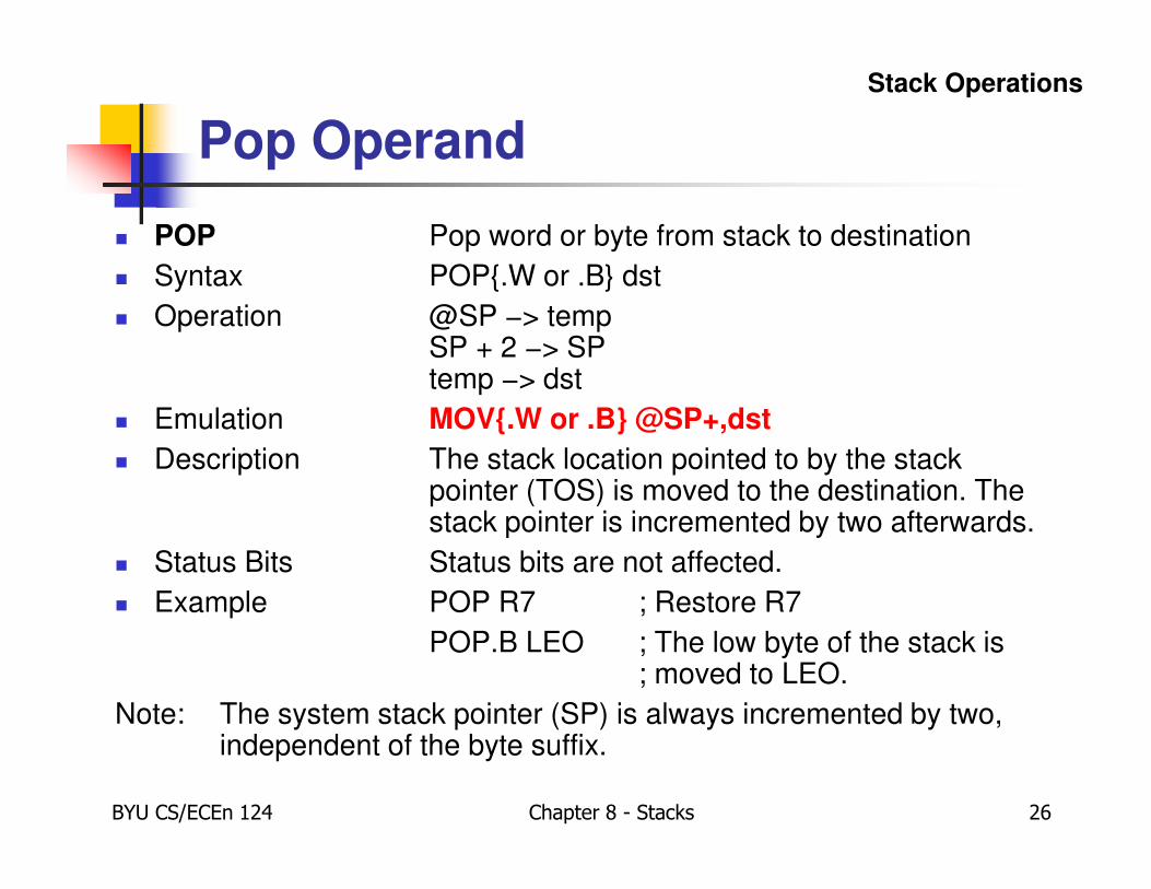
Pop Operand
� POP Pop word or byte from stack to destination
� Syntax POP{.W or .B} dst
� Operation @SP −> tempSP + 2 −> SPtemp −> dst
� Emulation MOV{.W or .B} @SP+,dst
� Description The stack location pointed to by the stack pointer (TOS) is moved to the destination. The stack pointer is incremented by two afterwards.
� Status Bits Status bits are not affected.
� Example POP R7 ; Restore R7
POP.B LEO ; The low byte of the stack is ; moved to LEO.
Note: The system stack pointer (SP) is always incremented by two, independent of the byte suffix.
Stack Operations
SP
r15
r14
0xf826
SP
BYU CS/ECEn 124 Chapter 8 - Stacks 27
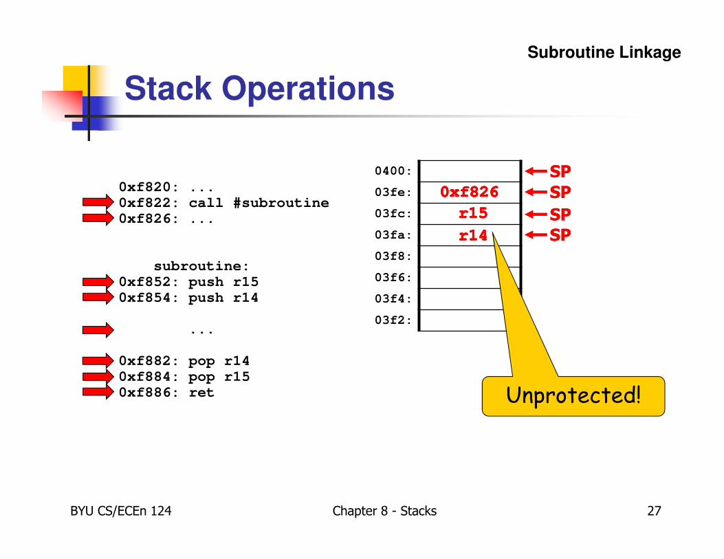
Stack Operations
Subroutine Linkage
0xf820: ...0xf822: call #subroutine0xf826: ...
subroutine:0xf852: push r150xf854: push r14
...
0xf882: pop r140xf884: pop r150xf886: ret
0400:
03fe:
03fc:
03fa:
03f8:
03f6:
03f4:
03f2:
Unprotected!
0xf826 SP
r15
0xf826
SPr15
r14
0xf826 SPr15
r14
0xf826
SP
r14
r15
0xf826
SPr14
r15
0xf826
SP
BYU CS/ECEn 124 Chapter 8 - Stacks 28
Activation Records
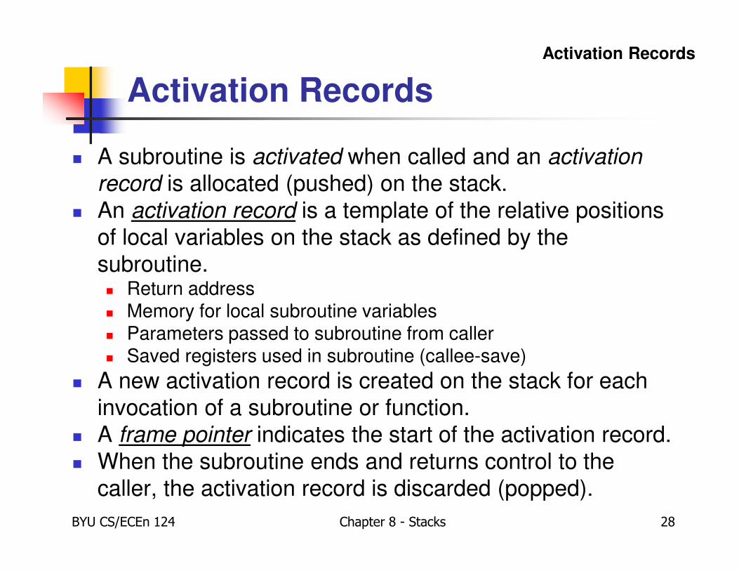
� A subroutine is activated when called and an activation
record is allocated (pushed) on the stack.
� An activation record is a template of the relative positions
of local variables on the stack as defined by the
subroutine.� Return address� Memory for local subroutine variables� Parameters passed to subroutine from caller� Saved registers used in subroutine (callee-save)
� A new activation record is created on the stack for each
invocation of a subroutine or function.
� A frame pointer indicates the start of the activation record.
� When the subroutine ends and returns control to the
caller, the activation record is discarded (popped).
Activation Records
BYU CS/ECEn 124 Chapter 8 - Stacks 29
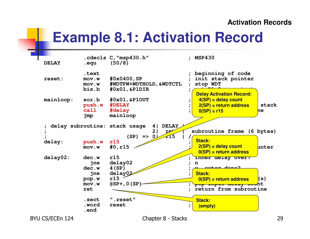
.cdecls C,"msp430.h" ; MSP430DELAY .equ (50/8)
.text ; beginning of codereset: mov.w #0x0400,SP ; init stack pointer
mov.w #WDTPW+WDTHOLD,&WDTCTL ; stop WDTbis.b #0x01,&P1DIR ; set P1.0 as output
mainloop: xor.b #0x01,&P1OUT ; toggle P1.0push.w #DELAY ; pass delay count on stackcall #delay ; call delay subroutinejmp mainloop
; delay subroutine: stack usage 4| DELAY | \; 2| ret | subroutine frame (6 bytes); (SP) => 0| r15 | /delay: push.w r15 ; callee-save
mov.w #0,r15 ; use R15 as inner counter
delay02: dec.w r15 ; inner delay over?jne delay02 ; n
dec.w 4(SP) ; y, outer done?jne delay02 ; n
pop.w r15 ; y, restore register(s)mov.w @SP+,0(SP) ; pop input delay countret ; return from subroutine
.sect ".reset" ; MSP430 reset Vector
.word reset ; start address
.end
Example 8.1: Activation Record
Delay Activation Record:4(SP) = delay count2(SP) = return address0(SP) = r15
Activation Records
Stack:2(SP) = delay count0(SP) = return address
Stack:0(SP) = return address
Stack:(emply)
BYU CS/ECEn 124 Chapter 8 - Stacks 30
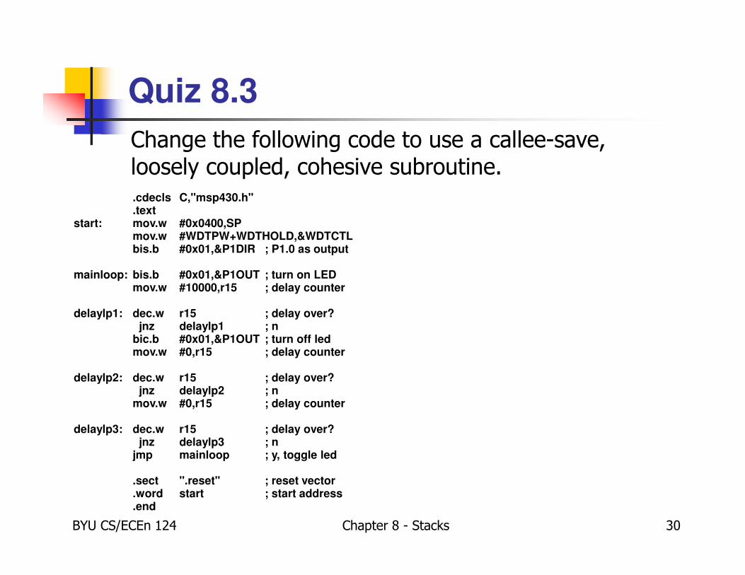
Quiz 8.3
Change the following code to use a callee-save, loosely coupled, cohesive subroutine..cdecls C,"msp430.h".text
start: mov.w #0x0400,SPmov.w #WDTPW+WDTHOLD,&WDTCTLbis.b #0x01,&P1DIR ; P1.0 as output
mainloop: bis.b #0x01,&P1OUT ; turn on LEDmov.w #10000,r15 ; delay counter
delaylp1: dec.w r15 ; delay over?jnz delaylp1 ; n
bic.b #0x01,&P1OUT ; turn off ledmov.w #0,r15 ; delay counter
delaylp2: dec.w r15 ; delay over?jnz delaylp2 ; n
mov.w #0,r15 ; delay counter
delaylp3: dec.w r15 ; delay over?jnz delaylp3 ; n
jmp mainloop ; y, toggle led
.sect ".reset" ; reset vector
.word start ; start address
.end

BYU CS/ECEn 124 Chapter 8 - Stacks 31
Recursive Subroutine
� A subroutine that makes a call to itself is said to be a
recursive subroutine.
� Recursion allows direct implementation of functions
defined by mathematical induction and recursive divide
and conquer algorithms
� Factorial, Fibonacci, summation, data analysis
� Tree traversal, binary search
� Recursion solves a big problem by solving one or more
smaller problems, and using the solutions of the smaller
problems, to solve the bigger problem.
� Reduces duplication of code.
� MUST USE STACK!
Recursive Subroutines
BYU CS/ECEn 124 Chapter 8 - Stacks 32
Interrupts
� Execution of a program normally proceeds predictably, with interrupts being the exception.
� An interrupt is an asynchronous signal indicating something needs attention.
� Some event has occurred
� Some event has completed
� The processing of an interrupt subroutine uses the stack.
� Processor stops with it is doing,
� stores enough information on the stack to later resume,
� executes an interrupt service routine (ISR),
� restores saved information from stack (RETI),
� and then resumes execution at the point where the processor was executing before the interrupt.
Interrupts
BYU CS/ECEn 124 Chapter 8 - Stacks 33
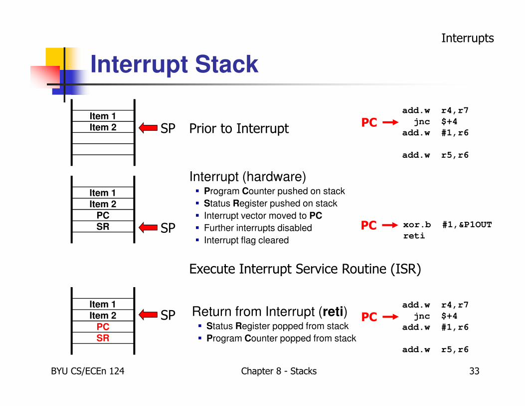
Interrupt Stack
Interrupts
Execute Interrupt Service Routine (ISR)
Item 2Item 1
Prior to InterruptSP
add.w r4,r7
jnc $+4
add.w #1,r6
add.w r5,r6
PC
Interrupt (hardware)� Program Counter pushed on stack
� Status Register pushed on stack
� Interrupt vector moved to PC
� Further interrupts disabled
� Interrupt flag cleared
SR
PC
Item 2
Item 1
SP xor.b #1,&P1OUT
retiPC
Return from Interrupt (reti)� Status Register popped from stack
� Program Counter popped from stackSR
PC
Item 2
Item 1
SPadd.w r4,r7
jnc $+4
add.w #1,r6
add.w r5,r6
PC
BYU CS/ECEn 124 Chapter 8 - Stacks 34