Embed Size (px)
Citation preview
Chapter 7A Peer-to-Peer Framework for SupportingMapReduce Applications in DynamicCloud EnvironmentsFabrizio Marozzo, Domenico Talia, and Paolo Trunfio
MapReduce is a programming model widely used in Cloud computing environments for processing large data sets in a highly parallel way. MapReduce implementations are based on a master-slave model. The failures of a slave is managed by re-assigning its task to another slave, while master failures are not managed by current MapReduce implementations, as designers consider failures unlikely in reliable Cloud systems. On the contrary, node failures – including master failures – are likely to happen in dynamic Cloud scenarios, where computing nodes may join and leave the network at an unpredictable rate.
Abstract
Therefore, providing effective mechanisms to manage master failures is fundamental to exploit the MapReduce model in the implementation of data-intensive applications in those dynamic Cloud environments where current MapReduce implementations could be unreliable. The goal of our work is to extend the master-slave architecture of current MapReduce implementations to make it more suitable for dynamic Cloud scenarios. In particular, in this chapter, we present a Peer-to-Peer (P2P)-MapReduce framework that exploits a P2P model to manage participation of intermittent nodes, master failures, and MapReduce job recovery in a decentralized but effective way.
Abstract

Cloud computing is gaining increasing interest both in science and industry for its promise to deliver service-oriented remote access to hardware and software facilities in a highly reliable and transparent way. A key point for the effective implementation of large-scale Cloud systems is the availability of programming models that support a wide range of applications and system scenarios. One of the most successful programming models currently adopted for the implementation of data-intensive Cloud applications is MapReduce [1].
7.1 Introduction
MapReduce defines a framework for processing large data sets in a highly parallel way by exploiting computing facilities available in a large cluster or through a Cloud system. In MapReduce, users specify the computation in terms of a map function that processes a key/value pair to generate a list of intermediate key/value pairs, and a reduce function that merges all intermediate values associated with the same intermediate key.
7.1 Introduction
7.1 Introduction
MapReduce implementations (e.g., Google’s MapReduce [2] and Apache Hadoop [3]) are based on a master-slave model. A job is submitted by a user node to a master node that selects idle workers and assigns each one a map or a reduce task. When all map and reduce tasks have been completed, the master node returns the result to the user node.
The failure of a worker is managed by re-executing its task on another worker, while current MapReduce implementations do not cope with master failures, as designers consider failures unlikely in large clusters or reliable Cloud environments.
7.1 Introduction

7.1 Introduction
• On the contrary, node failures – including master failures – can occur in large clusters and are likely to happen in dynamic Cloud environments such as an Intercloud, a Cloud of clouds, where computing nodes may join and leave the system at an unpredictable rate. Therefore, providing effective mechanisms to manage master failures is fundamental to exploit the MapReduce model in the implementation of data-intensive applications in large dynamic Cloud environments where current MapReduce implementations could be unreliable.
The goal of our work is to study how the master-slave architecture of current MapReduce implementations can be improved to make it more suitable for dynamic Cloud scenarios such as Interclouds.In this chapter, we present a Peer-to-Peer (P2P)-MapReduce framework that exploits a P2P model to manage participation of intermittent nodes, master failures, and MapReduce job recovery in a decentralized but effective way. An early version of this work, presenting a preliminary architecture of the P2P-MapReduce framework, has been presented in [4]. This chapter extends the previous work by describing an implementation of the P2P-MapReduce framework and a preliminary performance evaluation.
7.1 Introduction
The remainder of this chapter is organized as follows. Section 2 provides a background to the MapReduce programming model. Section 3 describes the P2P-MapReduce architecture, its current implementation, and preliminary evaluation of its performance. Finally, Section 4 concludes the chapter.
7.1 Introduction
7.2 MapReduce
• As mentioned earlier, MapReduce applications are based on a master-slave model. This section briefly describes the various operations that are performed by a generic application to transform input data into output data according to that model.
• Users define a map and a reduce function [1]. The map function processes a (key, value) pairs and returns a list of intermediate (key, value) pairs:
The whole transformation process can be described through the following steps (see Fig. 7.1):
1.A master process receives a “job configuration” describing the MapReduce job to be executed. The job configuration specifies, amongst other information, the location of the input data, which is normally a directory in a distributed file system.
7.2 MapReduce

7.2 MapReduce
7.2 MapReduce
• 2. According to the job configuration, the master starts a number of mapper and reducer processes on different machines. At the same time, it starts a process that reads the input data from its location, partitions that data into a set of splits, and distributes those splits to the various mappers.
• 3. After receiving its piece of data, each mapper process executes the map function (provided as part of the job configuration) to generate a list of intermediate key/value pairs. Those pairs are then grouped on the basis of their keys.
4.All pairs with the same keys are assigned to the same reducer process. Hence, each reducer process executes the reduce function (defined by the job configuration), which merges all the values associated with the same key to generate a possibly smaller set of values.
5.The results generated by each reducer process are then collected and delivered to a location specified by the job configuration, so as to form the final output data.
7.2 MapReduce

Besides the original MapReduce implementation by Google [2], several other MapReduce implementations have been realized within other systems, including Hadoop [3], GridGain [5], Skynet [6], MapSharp [7], and Disco [8]. Another system sharing most of the design principles of MapReduce is Sector/Sphere [9], which has been designed to support distributed data storage and processing over large Cloud systems. Sector is a high-performance distributed file system, and Sphere is a parallel data processing engine used to process Sector data files. In [10], a distributed data mining application developed using such system has been described.
7.2 MapReduce
Several applications of the MapReduce paradigm have been demonstrated. In [11], some examples of interesting applications that can be expressed as MapReduce computations, including: performing a distributed grep, counting URL access frequency, building a reverse Web-link graph, building a term-vector per host, and building inverted indices, performing a distributed sort. In [3], many significant types of applications that have been (or are being) implemented by exploiting the MapReduce model, including machine learning and data mining, log file analysis, financial analysis, scientific simulation, image retrieval and processing, blog crawling, machine translation, language modeling, and bioinformatics have been mentioned.
7.2 MapReduce
The objective of the P2P-MapReduce framework is twofold: (i) handling master failures by dynamically replicating the job state on a set of backup masters; (ii) supporting MapReduce applications over dynamic networks composed by nodes that join and leave the system at unpredictable rates.To achieve these goals, P2P-MapReduce exploits the P2P paradigm by defining an architecture in which each node can act either as a master or slave. The role assigned to a given node depends on the current characteristics of that node, and hence, it can change dynamically over time. Thus, at each time, a limited set of nodes is assigned the master role, while the others are assigned the slave role.
7.3 P2P-MapReduce
Moreover, each master node can act as a backup node for other master nodes. A user node can submit the job to one of the master nodes, which will manage it as usual in MapReduce. That master will dynamically replicate the entire job state (i.e., the assignments of tasks to nodes, the locations of intermediate results, etc.) on its backup nodes. In case those backup nodes detect the failure of the master, they will elect a new master among them that will manage the job computation using its local replica of the job state.The remainder of this section describes the architecture of the P2P-MapReduce framework, its current implementation, and a preliminary evaluation of its performance.
7.3 P2P-MapReduce
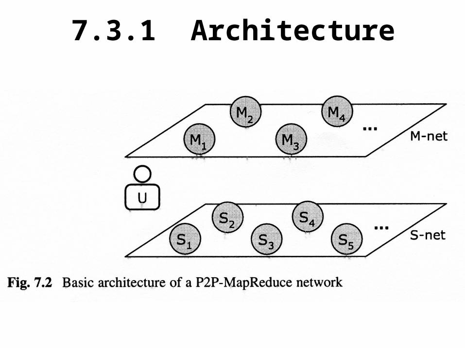
The P2P-MapReduce architecture includes three basic roles, shown in Fig. 7.2: user (U), master(M), and slave(S). Master nodes and slave nodes form two logical P2P networks called M-net and S-net, respectively. As mentioned earlier, computing nodes are dynamically assigned the master or slave role, and hence, M-net and S-Net change their composition over time. The mechanisms used for maintaining this infrastructure are discussed in Section 3.2.In the following, we describe, through an example, how a master failure is handled in the P2P-MapReduce architecture. We assume the initial configuration represented in Fig. 7.2, where U us the user node that submits a MapReduce job, nodes M are the masters, and nodes S are the slaves.
7.3.1 Architecture
7.3.1 Architecture
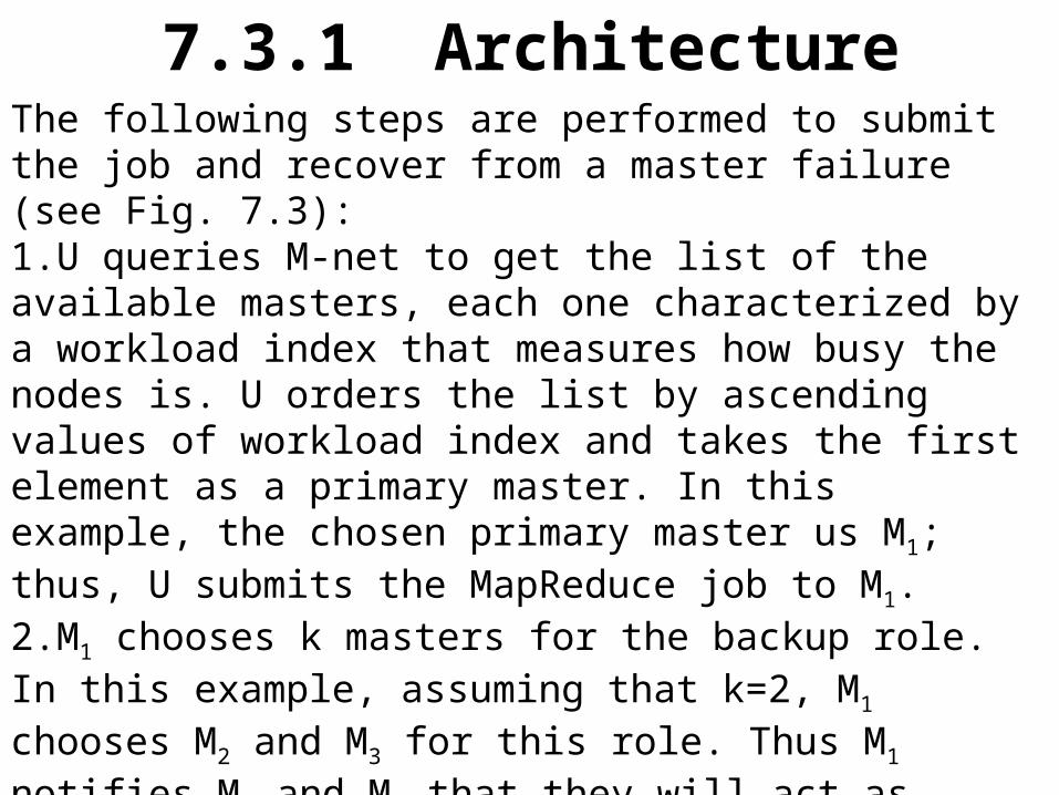
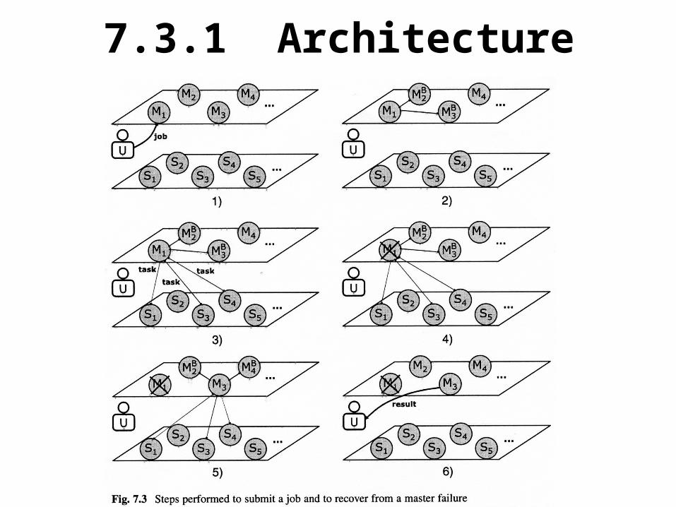
The following steps are performed to submit the job and recover from a master failure (see Fig. 7.3):1.U queries M-net to get the list of the available masters, each one characterized by a workload index that measures how busy the nodes is. U orders the list by ascending values of workload index and takes the first element as a primary master. In this example, the chosen primary master us M1; thus, U submits the MapReduce job to M1.2.M1 chooses k masters for the backup role. In this example, assuming that k=2, M1 chooses M2 and M3 for this role. Thus M1 notifies M2 and M3 that they will act as backup nodes for the current job (in Fig. 7.3, that apex “B” to nodes M2 and M3 indicates the backup function). This implies that whenever the job state changes, M1 backs up it on M2 and M3, which in turn will periodically check whether M1 is alive.
7.3.1 Architecture
7.3.1 Architecture
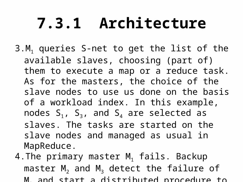
3. M1 queries S-net to get the list of the available slaves, choosing (part of) them to execute a map or a reduce task. As for the masters, the choice of the slave nodes to use us done on the basis of a workload index. In this example, nodes S1, S3, and S4 are selected as slaves. The tasks are started on the slave nodes and managed as usual in MapReduce.
4. The primary master M1 fails. Backup master M2 and M3 detect the failure of M1 and start a distributed procedure to elect a new primary master among them.
7.3.1 Architecture
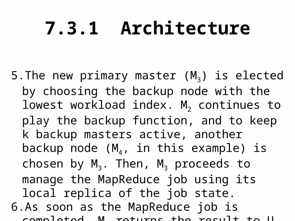
5. The new primary master (M3) is elected by choosing the backup node with the lowest workload index. M2 continues to play the backup function, and to keep k backup masters active, another backup node (M4, in this example) is chosen by M3. Then, M3 proceeds to manage the MapReduce job using its local replica of the job state.
6. As soon as the MapReduce job is completed, M3 returns the result to U.
7.3.1 Architecture
It is worth noticing that the master failure and the subsequent recovery procedure are transparent to the user. It should also be noted that a master node may simultaneously play the role of primary master for one job and that of backup master for another job.
7.3.1 Architecture

7.3.2 Implementation
• We implemented a prototype of the P2P-MapReduce framework using the JXTA framework [12]. JXTA provides a set of XML-based protocols that allow computers and other devices to communicate and collaborate in a P2P fashion. Each peer provides a set of programs made available to other peers in the network. Services and any type of programs that can be networked by a single or a group of peers.
In JXTA, there are two main types of peers: rendezvous and edge. The rendezvous peers act as routers in a networks, forwarding the discovery requests submitted by edge peers to locate the resources of interest. Peers sharing a common set of interests are organized into a peer group. To send message to each other, JXTA peers use asynchronous communication mechanisms called pipes. Pipes can be either point-to-point or multicast, so as to support a wide range of communication schemes. All resources (peers, services, etc.) are described by advertisements that are published within the peer group of resource-discovery purposes.
7.3.2 Implementation
In the following, we briefly describe how the JXTA components are used in the P2P-MapReduce system to implement basic mechanisms for resource discovery, network maintenance, job submission, and failure recovery. Then, we describe the state diagram that steers the behavior of a generic node and the software modules provided by each node in a P2P-MapReduce network.
7.3.2 Implementation
Resource Discovery
All master and slave nodes in the P2P-MapReduce system belong to a single JXTA peer group called MapReduceGroup. Most of these nodes are edge peers, but some of them also act as rendezvous peers, in a way that is transparent to the users. Each node exposes its features by publishing an advertisement containing basic information, such as its Role and Workloadindex.
7.3.2.1 Basic Mechanisms

An edge peer publishes its advertisement in a local cache and sends some keys identifying that advertisement to a rendezvous peer. The rendezvous peer uses those keys to index the advertisement in a distributed hash table called Shared Resource Distributed Index (SRDI), managed by all the rendezvous peers of MapReduceGroup. Queries for a given type of resource (e.g., master nodes) are submitted to the JXTA Discovery Services that uses SRDI to locate all the resources of that type without flooding the entire network.Note that M-net and S-net, represented in Fig. 7.2, are “logical” networks in the sense that queries to M-net (or S-net) are actually submitted to the whole MapReduceGroup, but restricted to nodes having the attribute Role set to “Master” (or “slave”) using the SRDI mechanisms.
7.3.2.1 Basic Mechanisms
Network Maintenance
Network maintenance is carried out cooperatively by all nodes on the basis of their role. The maintenance task of each slave node is to periodically check the existence of at least one master in the network. In case no masters are found, the slave promotes itself to the master role. In this way, the first node joining the network always assumes the master role. The same happens to the last node remaining into the network.
7.3.2.1 Basic Mechanisms
The maintenance task of master nodes is to ensure the existence of a given percentage p of masters on the total number of nodes. This task us performed periodically by one master only (referred to as coordinator), which is elected for this purpose among all the masters using a variation of the “bully” election algorithm. The coordinator has the power of changing slaves into masters, and vice versa. During a maintenance operation, the coordinator queries all nodes and orders them by ascending values of workload index: the first p percent of nodes must assume (or maintain) the master role, while the others will become or remain slaves. Nodes that have to change their role are notified by the coordinator in order to update their status.
7.3.2.1 Basic Mechanisms
Job Submission and Failure Recovery
To describe the JXTA mechanisms used for job submission and mater-failure recovery, we take six-point example presented in Section 3.1 as reference:
1.The user node invokes the Discovery Service to obtain the advertisements of the master nodes published in MapReduceGroup. Based in the WorkloadIndex, it chooses the primary master for its job. Then, it opens a bidirectional pipe (called PrimaryPipe) to the primary master and submits the job configuration.
7.3.2.1 Basic Mechanisms
7.3.2.1 Basic Mechanisms
2. The primary master invokes the Discovery Service to choose its backup masters and opens a multicast pipe (Backuppipe) to the backup masters. The BackupPipe has two goals: replicating job state information to the backup nodes and allowing backup nodes to detect a primary master failure in case the BackupPipe connection times out.
3. The primary master invokes the Discovery Service to select the slave nodes to be used for the job. Slave nodes are filtered on the basis of WorkloadIndex attribute. The primary master opens a bidirectional pipe (SlavePipe) to each slave and starts a map or a reduce task on it.
4. The backup masters detect a primary master failure (i.e., a timeout on the BackupPipe connection) and start a procedure to elect the new primary master (to this end, they connect each other with a temporary pipe and exchange information about their current WorkloadIndex).
7.3.2.1 Basic Mechanisms

5. The backup master with the lowest WorkloadIndex is elected as the new primary master. This new primary master binds the pipes previously associated with the old primary master (PrimaryPipe, BackupPipe and SlavePipes), chooses (and connect to) a substitute backup master, and then continues to manage the MapReduce job using its replica of the job state.
6. The primary master returns the result of the MapReduce job to the user node through the PrimaryPipe.
7.3.2.1 Basic Mechanisms

7.3.2.1 Basic Mechanisms
The primary master detects the failure of a slave by getting a timeout to the associated SlavePipe connection. If this event occurs, a new slave is selected and the failed map or reduce task is assigned to it.
The behavior of a generic node is modeled as a state diagram that defines the different states that a node can assume, and all the events that determine the transitions from one state to another one. Figure 7.4 shows such a diagram modeled using the UML State Diagram formalism.The state diagram includes two macro-states, SLAVE and MASTER, which describes the two roles that can be assumed by each node. The SLAVE state has three states, IDLE, CHECK_MASTER_EXISTENCE, and ACTIVE, which represent a slave waiting for task assignment, a slave checjking the existence of a master, and a slave executing a given task, respectively.
7.3.2.2 State Diagram and Software Modules

The MASTER state is modeled with three parallel macro-states, which represent the different roles that a master can perform concurrently: possibly acting as a primary master for one or more jobs (MANAGEMENT), possibly acting as a backup master for one or more jobs (RECOVERY), and coordinating the network for maintenance purposes (COORDINATION).The MANAGEMENT macro-state contains two states: NOT_PRIMARY, which represents a master node currently not acting as a primary master for any job, and PRIMARY, which in contrast, represents a master node currently managing at least one job as a primary master.
7.3.2.2 State Diagram and Software Modules
Similarly, the RECOVERY macro-state includes two states: NOT_BACKUP (the node is not managing any job as a backup master), COORDINATOR (the node is acting as coordinator), WAITING_COORDINATOR, and ELECTING_COORDINATOR for nodes currently participating in the election of the new coordinator, as mentioned in Section 3.2.1.
7.3.2.2 State Diagram and Software Modules
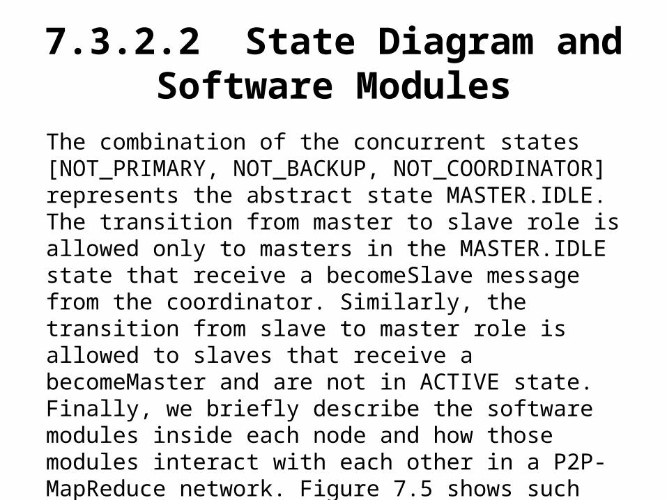
The combination of the concurrent states [NOT_PRIMARY, NOT_BACKUP, NOT_COORDINATOR] represents the abstract state MASTER.IDLE. The transition from master to slave role is allowed only to masters in the MASTER.IDLE state that receive a becomeSlave message from the coordinator. Similarly, the transition from slave to master role is allowed to slaves that receive a becomeMaster and are not in ACTIVE state. Finally, we briefly describe the software modules inside each node and how those modules interact with each other in a P2P-MapReduce network. Figure 7.5 shows such modules and interactions using the UML Deployment/Component Diagram formalism.
7.3.2.2 State Diagram and Software Modules
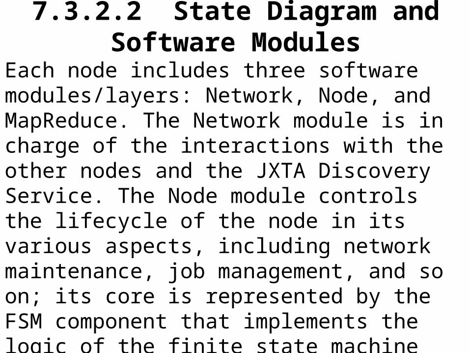
Each node includes three software modules/layers: Network, Node, and MapReduce. The Network module is in charge of the interactions with the other nodes and the JXTA Discovery Service. The Node module controls the lifecycle of the node in its various aspects, including network maintenance, job management, and so on; its core is represented by the FSM component that implements the logic of the finite state machine described in Fig. 7.4. The MapReduce module manages the local execution of jobs (wen the node is acting as a master) or tasks (when the node is acting as a slave).
7.3.2.2 State Diagram and Software Modules
We carried out a preliminary set of experiments to evaluate the behavior of the P2P-MapReduce framework when compared with a centralized implementation of MapReduce, in the presence of dynamic-nodes participation. The experimental results demonstrate that by using a P2P approach, it is possible to extend the MapReduce architectural module making it suitable for highly dynamic Cloud environments where failure must be managed to avoid a critical loss of computing resources and time.
7.3.3 Evaluation
The evaluation has been carried out by implementing a simulator of the system in which each node is represented by an independent thread. Each thread executes the algorithms specified by the state diagram in Fig. 7.4, and communicates with the other threads by invoking local routines having the same of the JXTA pipes. Our simulation analyzes the system in steady state, that is, when M-net and S-net are formed and the desired ratio between the number of masters and slaves is reached.
7.3.3 Evaluation
The network includes 1,000 nodes. To simulate dynamic-nodes participation, a joining rate RJ and a leaving rate RL are defined. On average, for every 1/RJs, one node joins the network, while for every 1/RL, another node abruptly leaves the network so as to simulate an event of failure (or a disconnection). In our simulation, RJ = RL in order to keep the total number of nodes and the master/slave ratio approximately constant during the whole simulation. In particular, we considered the following values for RJ and RL: 0.05, 0.1, and 0.2, which correspond to the join/failure of one node (out of 1,000 nodes)-every 20, 10, and 5 s, respectively.
7.3.3 Evaluation
For every 120 s (mean value), a user entity submits one job to the system. The average sequential duration of a job is 20 h that are distributed, on an average, to 100 nodes. On the basis of the actual number of slaves, the system determines the amount of time each slave will be busy to complete its tasks. Every node, other than managing a job or a task, executes the network-maintenance operations described earlier (election of the coordinator, choice of backup masters, etc.).
7.3.3 Evaluation
The main task performed by the simulator is evaluating the number of jobs failed versus the total number of jobs submitted to the system. For the purpose of our simulations, a “failed” job is a job that does not complete its execution, that is, it does not return a result to the submitting user. The failure of a job is always caused by an unmanaged failure of the master responsible for that job. The failure of a slave, on the contrary, never causes a failure of the whole job because its task is re-assigned to another slave.
7.3.3 Evaluation
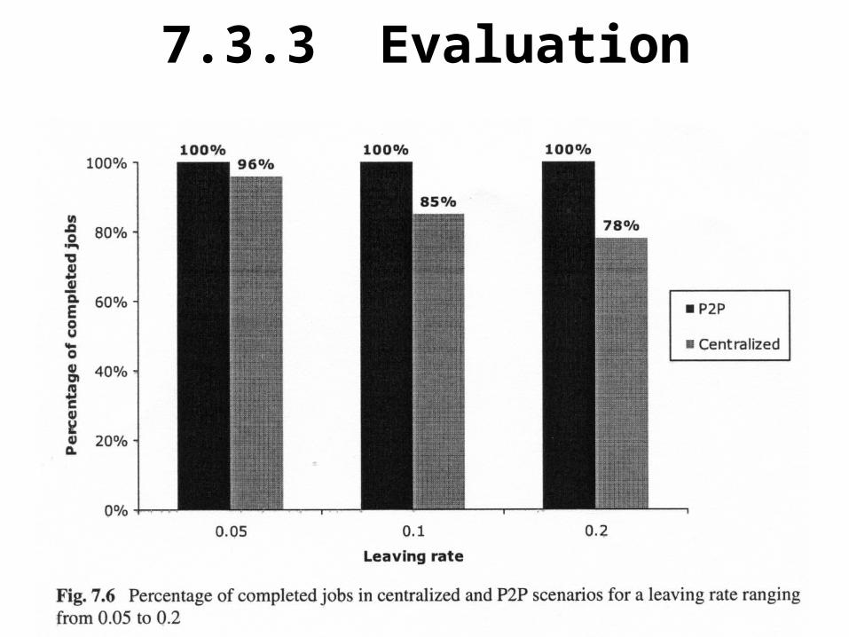
The system has been evaluated in two scenarios: (i) centralized, where there is only one primary master and there are no backup masters; (ii) P2P, where there are ten masters and each job is managed by one master that periodically replicates the job state on one backup master. Figure 7.6 presents the percentage of completed jobs in centralized and P2P scenarios after the submission of 100 jobs.
7.3.3 Evaluation
7.3.3 Evaluation
7.3.3 Evaluation
• As expected, in the centralized scenario the number of failed jobs increases as the leaving rate increases. In contrast, the P2P-MapReduce scenario is able to complete all the jobs for all the considered leaving rates, even if we used just one backup per job. It is worth noticing that when a backup master becomes primary master as a consequence of a failure, it chooses another backup in its place to maintain the desired level of reliability.
The percentages given in Fig. 7.6 can be translated into lost CPU hours, by multiplying the average job duration to the average number of failed jobs. In the centralized scenario, the absolute number of failed jobs is 4, 15, and 22 for leaving rates of 0.05, 0.1, and 0.2, respectively. Hence, with an average sequential duration of 20 h per job, the total number of lost computing hours equals, in the worst case, 80, 300, and 400 h.We can further estimate the amount of resources involved in a typical MapReduce job by taking the statistics about a large set of MapReduce jobs run at Google, presented in [1]. In March 2006, the average completion time per job was 874s, using 268 slaves on average.
7.3.3 Evaluation
By assuming that each machine is fully assigned to one job, the overall machine time is 874 x 268 s (about 65 h). In September 2007, the average job completion time was 395 s using 394 machines, with an overall machine time of 43 h.From the statistics reported earlier, and from the results generated by our experiments, we see that a master failure causes loss of dozens of CPU hours for a typical MapReduce job. Moreover, when the number of available machines per user is limited (as in a typical Cloud systems where resources are shared among thousands of users), a master failure also procedures a significant loss of time because the job completion time increase as the number of machines decreases.
7.3.3 Evaluation

Providing effective mechanisms to manage master failures, job recovery, and participation of intermittent nodes is fundamental to exploit the MapReduce model in the implementation of data-intensive applications in dynamic Cloud environments or Cloud of clouds scenarios where current MapReduce implementations could be unreliable.
7.4 Conclusions

7.4 Conclusions
• The P2P-MapReduce model presented in this chapter exploits a P2P model to perform job state replication, manage master failures, and allow participation of intermittent nodes in a decentralized but effective way. Using a P2P approach, we extended the MapReduce architectural model, making it suitable for highly dynamic environments where failure must be managed to avoid a critical loss of computing resources and time.