Embed Size (px)
Citation preview
1
Chapter 6 Inductance, Capacitance, and Mutual Inductance
6.1 The inductor6.2 The capacitor6.3 Series-parallel combinations of
inductance and capacitance6.4 Mutual inductance6.5 Closer look at mutual inductance

2
In addition to voltage sources, current sources, resistors, here we will discuss the remaining 2 types of basic elements: inductors, capacitors.
Inductors and capacitors cannot generate nor dissipate but store energy.
Their current-voltage (i-v) relations involve with integral and derivative of time, thus more complicated than resistors.
Overview
3
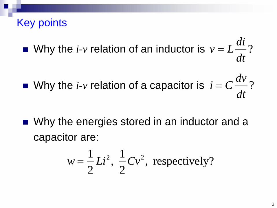
Why the i-v relation of an inductor is
Why the i-v relation of a capacitor is
Why the energies stored in an inductor and a capacitor are:
Key points
?dtdiLv
?dtdvCi
ly?respective ,21,
21 22 CvLiw

4
Section 6.1 The Inductor
1. Physics2. i-v relation and behaviors3. Power and energy
5
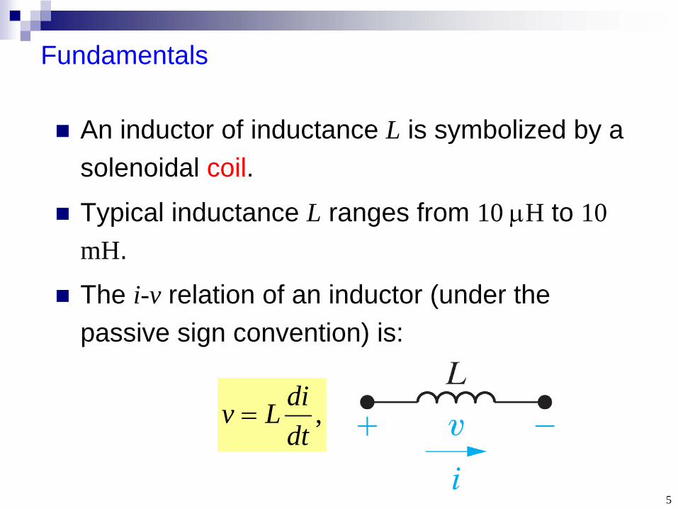
Fundamentals
An inductor of inductance L is symbolized by a solenoidal coil.
Typical inductance L ranges from 10 H to 10 mH.
The i-v relation of an inductor (under the passive sign convention) is:
,dtdiLv

6
Consider an N1 -turn coil C1 carrying current I1 . The resulting magnetic field (Biot- Savart law) will pass through C1 itself, causing a
Physics of self-inductance (1)
)(1 rB
,)(
,
111 11
111
1
INPsdrB
N
S
111 )( INrB
flux linkage 1 , where
P1 is the permeance.
.12111 INP
7
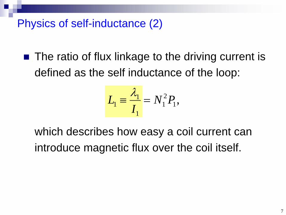
The ratio of flux linkage to the driving current is defined as the self inductance of the loop:
Physics of self-inductance (2)
,121
1
11 PN
IL
which describes how easy a coil current can introduce magnetic flux over the coil itself.
8
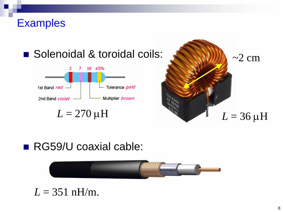
Examples
Solenoidal & toroidal coils:
RG59/U coaxial cable:
L = 351 nH/m.
L = 36 HL = 270 H
~2 cm
9
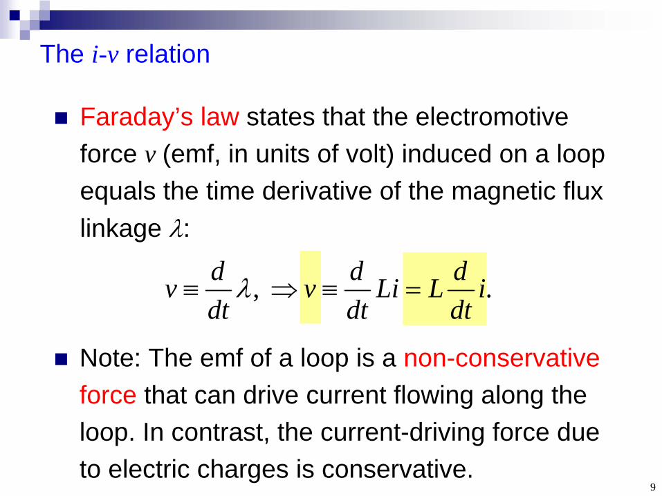
Faraday’s law states that the electromotive force v (emf, in units of volt) induced on a loop equals the time derivative of the magnetic flux linkage :
The i-v relation
. , idtdLLi
dtdv
dtdv
Note: The emf of a loop is a non-conservative force that can drive current flowing along the loop. In contrast, the current-driving force due to electric charges is conservative.

10
Behaviors of inductors
DC-current: inductor behaves as a short circuit.
Current cannot change instantaneously in an inductor, otherwise, infinite voltage will arise.
Change of inductor current is the integral of voltage during the same time interval:
dtdiLv
.)(1)()(0
0 t
tdv
Ltiti
11
Inductive effect is everywhere!
Nearly all electric circuits have currents flowing through conducting wires. Since it’s difficult to shield magnetic fields, inductive effect occurs even we do not purposely add an inductor into the circuit.
12
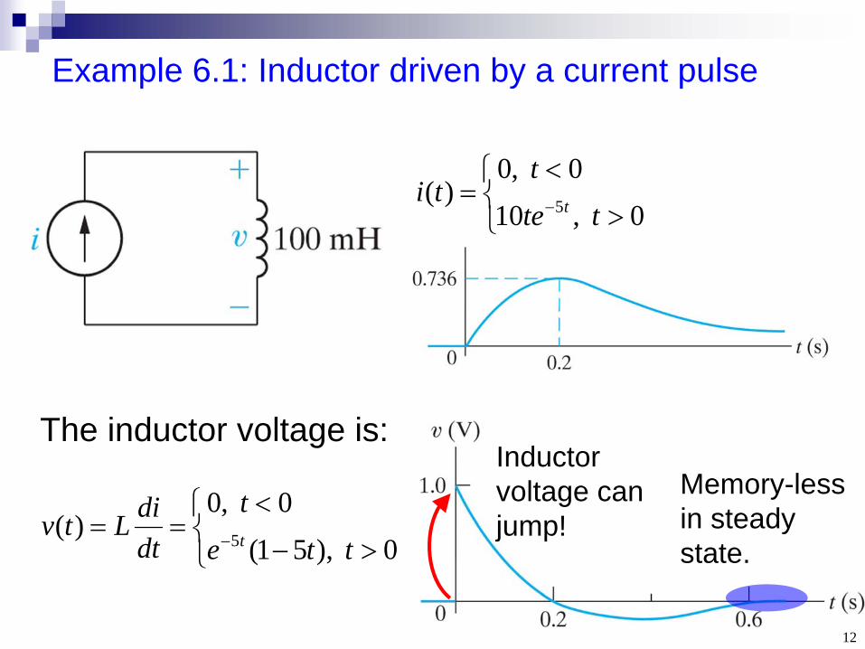
Example 6.1: Inductor driven by a current pulse
0 ,100 ,0
)( 5 ttet
ti t
The inductor voltage is:
0 ),51(0 ,0
)(5 ttet
dtdiLtv
t
Inductor voltage can jump!
Memory-less in steady state.
13
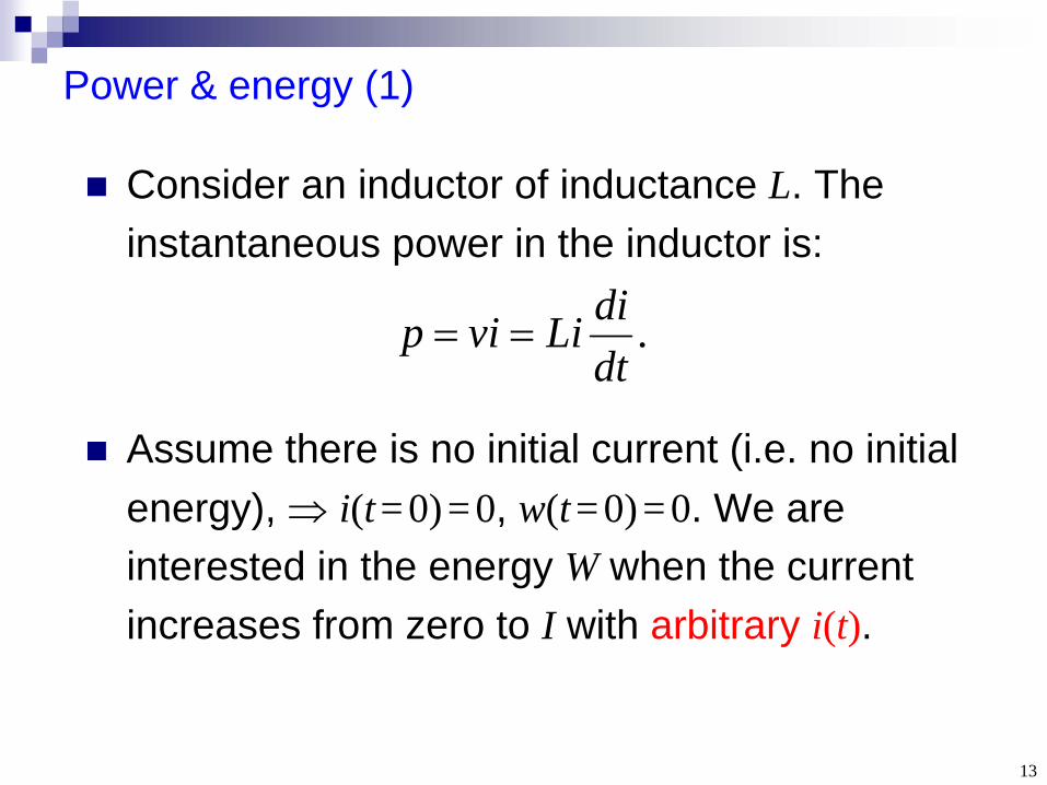
Consider an inductor of inductance L. The instantaneous power in the inductor is:
Assume there is no initial current (i.e. no initial energy), i(t =0)=0, w(t =0)=0. We are interested in the energy W when the current increases from zero to I with arbitrary i(t).
Power & energy (1)
.dtdiLivip
14
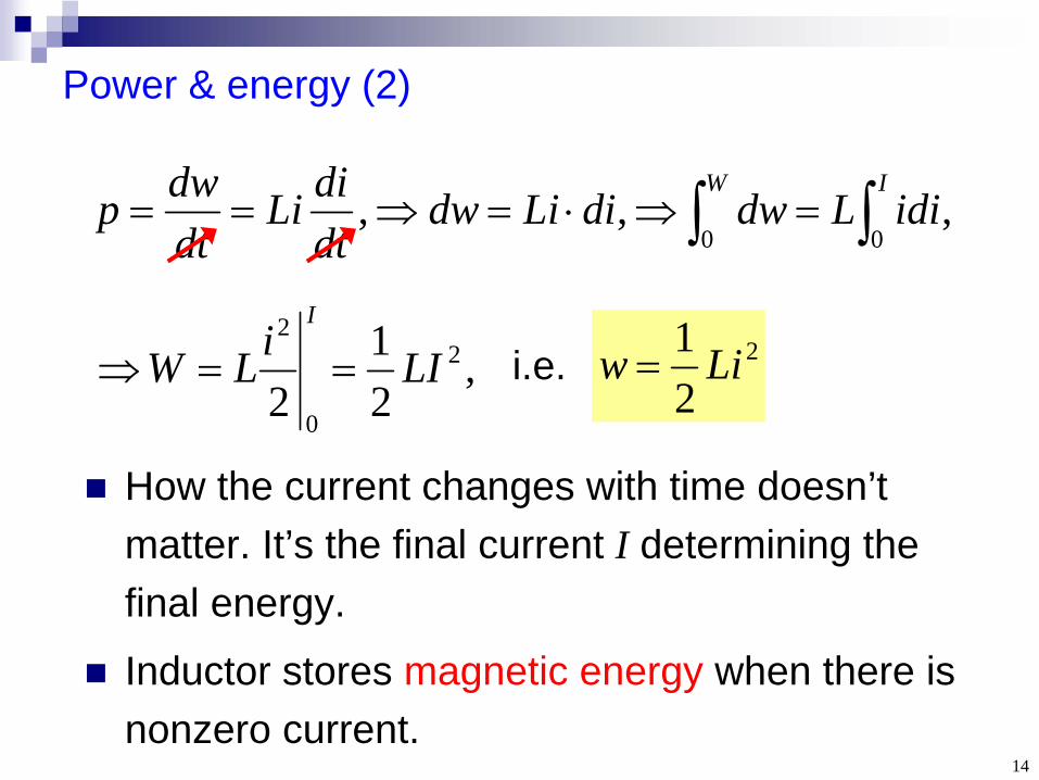
Power & energy (2)
2
21 Liw
, , ,00 IWidiLdwdiLidw
dtdiLi
dtdwp
i.e.,21
22
0
2
LIiLWI
How the current changes with time doesn’t matter. It’s the final current I determining the final energy.
Inductor stores magnetic energy when there is nonzero current.
15
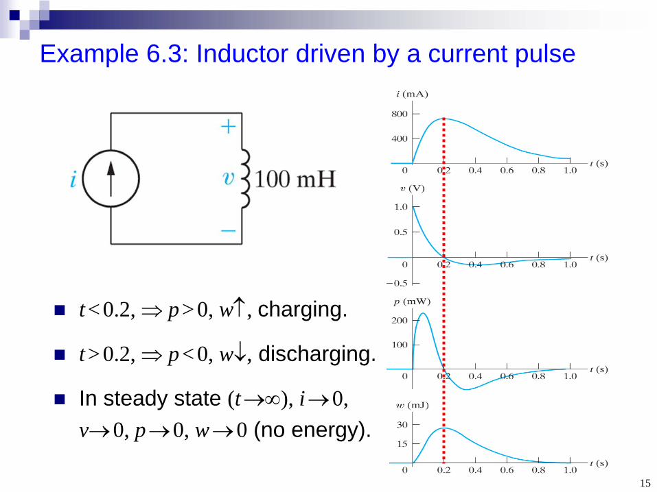
Example 6.3: Inductor driven by a current pulse
t < 0.2, p> 0, w, charging.
t > 0.2, p< 0, w, discharging.
In steady state (t ), i 0, v0, p0, w0 (no energy).
16
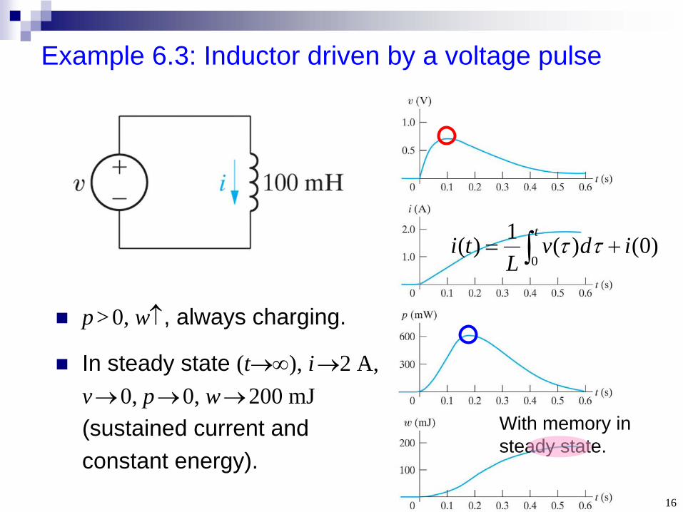
Example 6.3: Inductor driven by a voltage pulse
p> 0, w, always charging.
In steady state (t), i 2 A, v0, p0, w200 mJ (sustained current and constant energy).
)0()(1)(0
idvL
tit
With memory in steady state.

17
Section 6.2 The Capacitor
1. Physics2. i-v relation and behaviors3. Power and energy
18
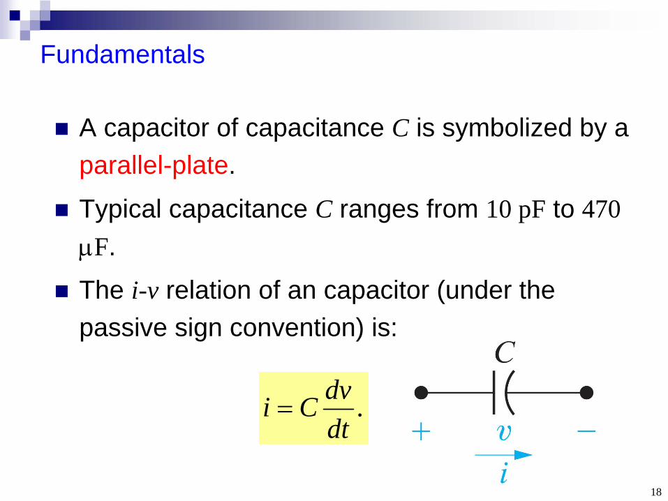
Fundamentals
A capacitor of capacitance C is symbolized by a parallel-plate.
Typical capacitance C ranges from 10 pF to 470 F.
The i-v relation of an capacitor (under the passive sign convention) is:
.dtdvCi
19
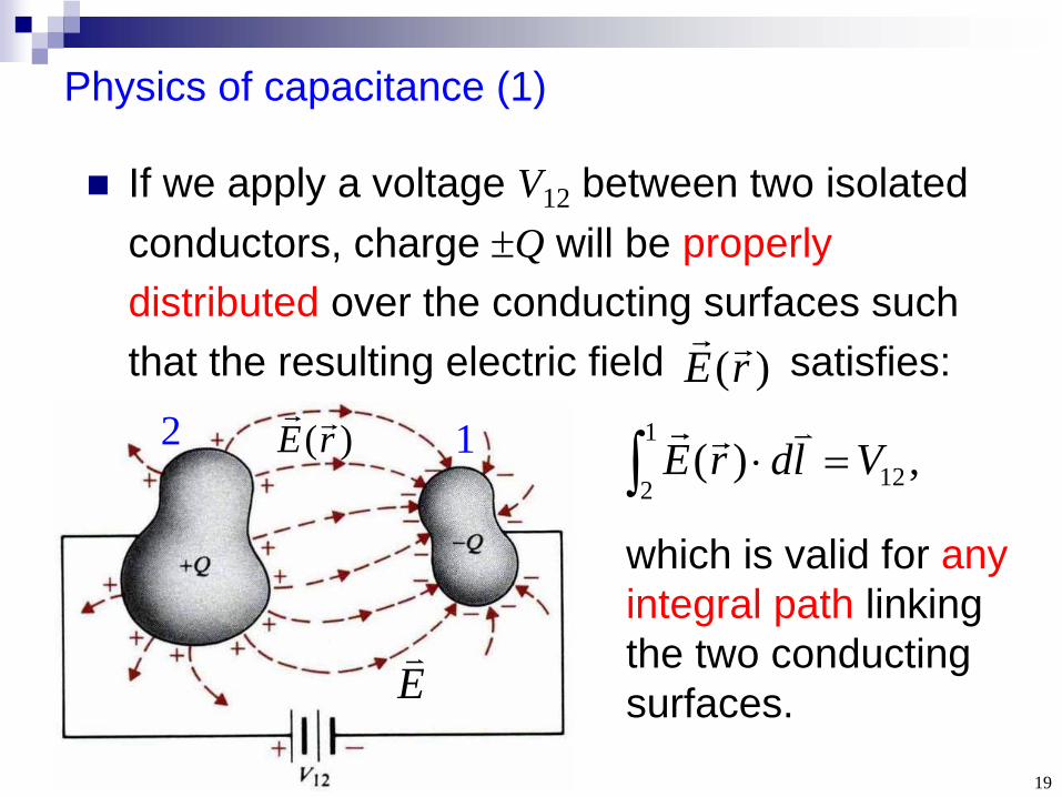
If we apply a voltage V12 between two isolated conductors, charge Q will be properly distributed over the conducting surfaces such that the resulting electric field satisfies:
Physics of capacitance (1)
)(rE
1B
which is valid for any integral path linking the two conducting surfaces.E
2 1 ,)(1
2 12 VldrE)(rE
20
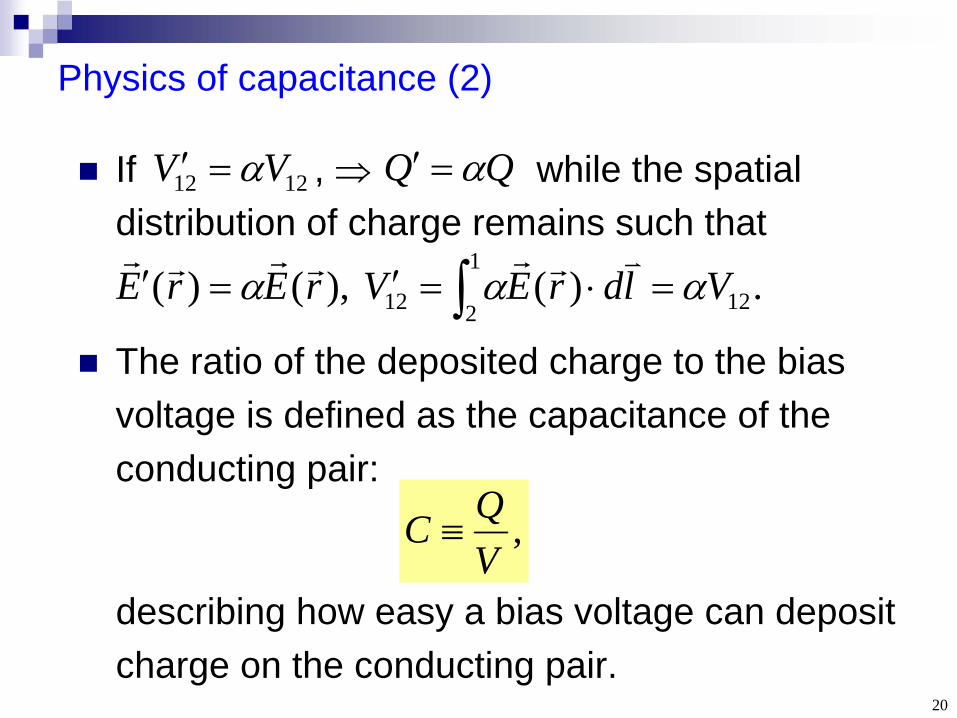
If ,
while the spatial distribution of charge remains such that
The ratio of the deposited charge to the bias voltage is defined as the capacitance of the conducting pair:
Physics of capacitance (2)
,VQC
describing how easy a bias voltage can deposit charge on the conducting pair.
.)( ),()(1
2 1212 VldrEVrErE
1212 VV QQ
21
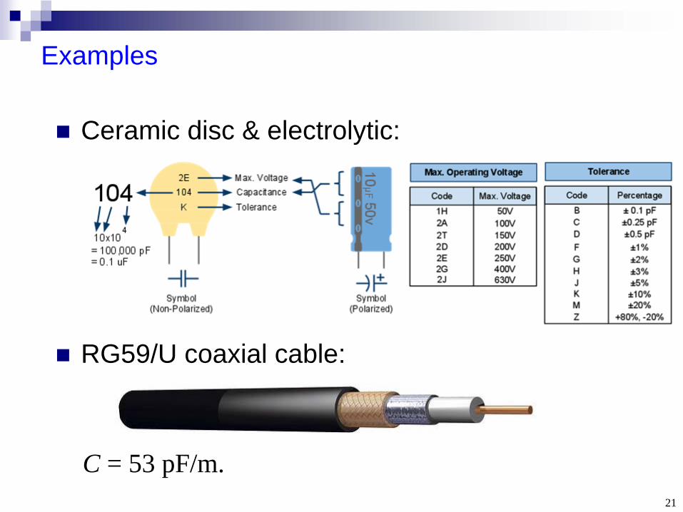
Examples
Ceramic disc & electrolytic:
RG59/U coaxial cable:
C = 53 pF/m.

22
From the definition of capacitance:
The i-v relation
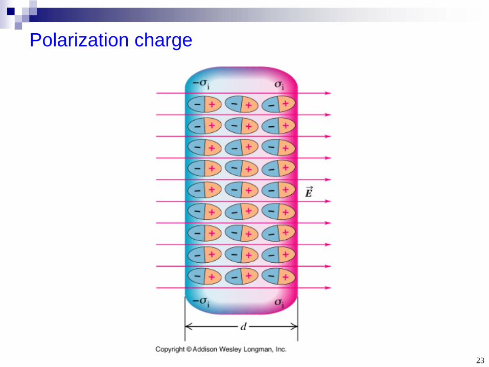
Note: Charge cannot flow through the dielectric between the conductors. However, a time-varying voltage causes a time-varying electric field that can slightly displace the dielectric bound charge. It is the time-varying bound charge contributing to the “displacement current”.
. , ),()( , vdtdCiv
dtdCq
dtdtCvtq
VQC
23
Polarization charge

24
Behaviors of capacitors
DC-voltage: capacitor behaves as an open circuit.
Voltage cannot change instantaneously in an capacitor, otherwise, infinite current will arise.
Change of capacitor voltage is the integral of current during the same time interval:
dtdvCi
.)(1)()(0
0 t
tdi
Ctvtv
25
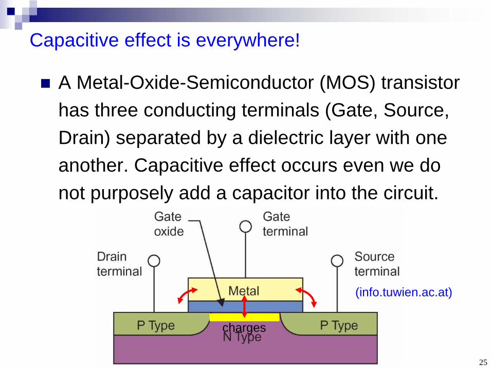
Capacitive effect is everywhere!
A Metal-Oxide-Semiconductor (MOS) transistor has three conducting terminals (Gate, Source, Drain) separated by a dielectric layer with one another. Capacitive effect occurs even we do not purposely add a capacitor into the circuit.
(info.tuwien.ac.at)
charges

26
Consider a capacitor of capacitance C. The instantaneous power in the capacitor is:
Assume there is no initial voltage (i.e. no initial energy), v(t =0)=0, w(t =0)=0. We are interested in the energy W when the voltage increases from zero to V with arbitrary v(t).
Power & energy (1)
.dtdvCvvip
27
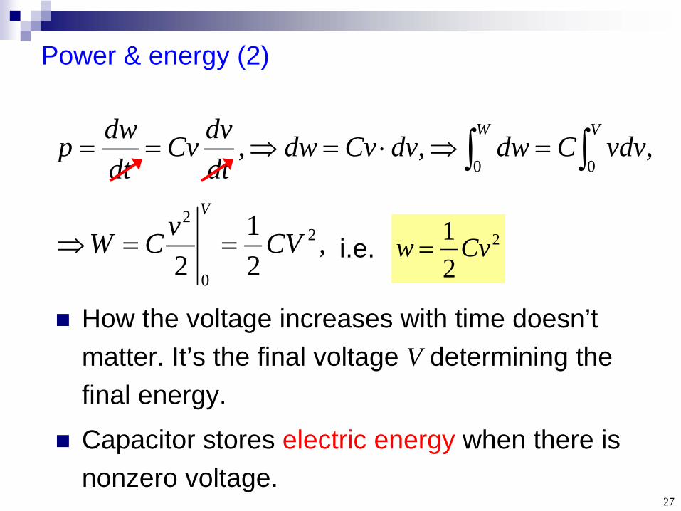
Power & energy (2)
How the voltage increases with time doesn’t matter. It’s the final voltage V determining the final energy.
Capacitor stores electric energy when there is nonzero voltage.
, , ,00 VW
vdvCdwdvCvdwdtdvCv
dtdwp
2
21 Cvw i.e.,
21
22
0
2
CVvCWV

28
Example 6.4: Capacitor driven by a voltage pulse
t < 1, p>0, w, charging.
t > 1, p<0, w, discharging.
In steady state (t), i 0, v 0, p0, w0 (no energy).
Capacitor current can jump!
Memory-less in steady state.

29
Section 6.3 Series-Parallel Combinations
1. Inductors in series-parallel2. Capacitors in series-parallel
30
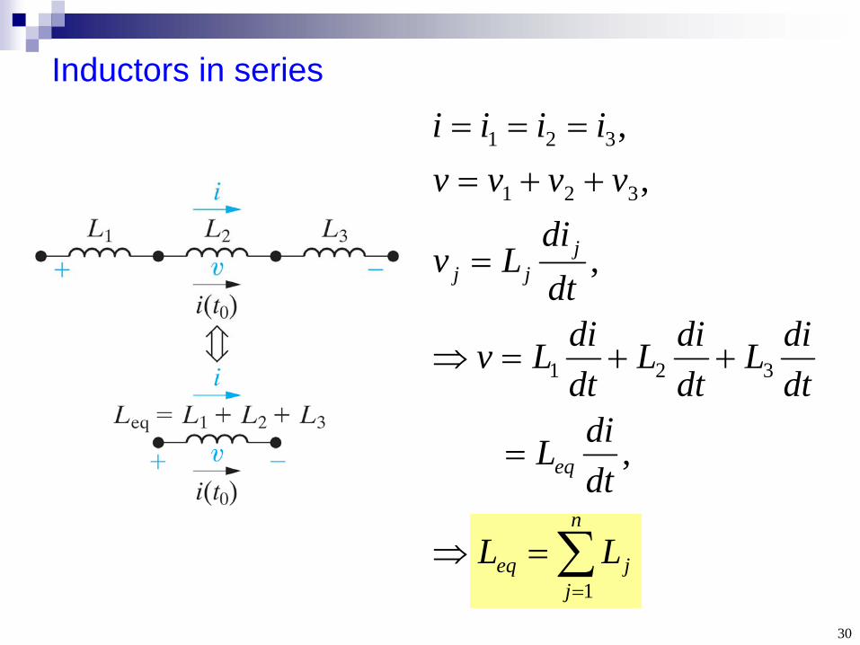
Inductors in series
n
jjeq
eq
jjj
LL
dtdiL
dtdiL
dtdiL
dtdiLv
dtdi
Lv
vvvviiii
1
321
321
321
,
,
,,
31
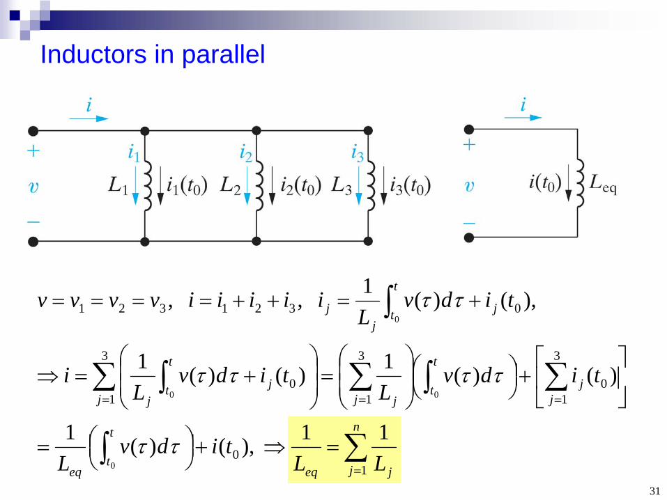
Inductors in parallel
n
j jeq
t
teq
jj
t
tj jj
j
t
tj
j
t
tj
j
LLtidv
L
tidvL
tidvL
i
tidvL
iiiiivvvv
10
3
10
3
1
3
10
0321321
11 ),()(1
)()(1)()(1
),()(1 , ,
0
00
0
32
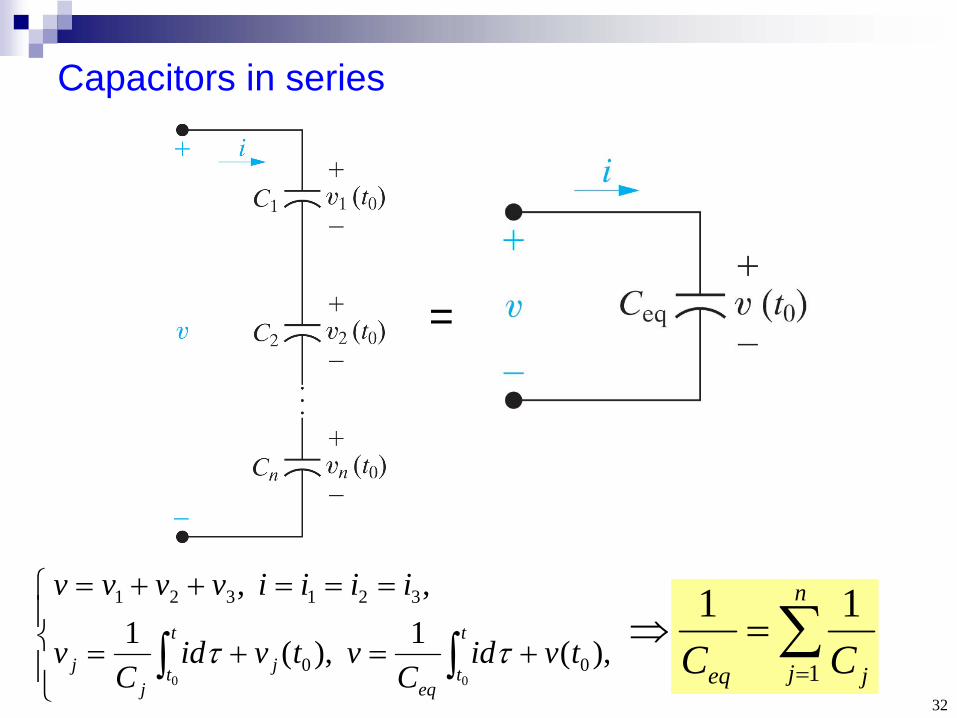
Capacitors in series
n
j jeq CC 1
11
=
),(1 ),(1, ,
00
321321
00
tvidC
vtvidC
v
iiiivvvvt
teq
j
t
tj
j
33
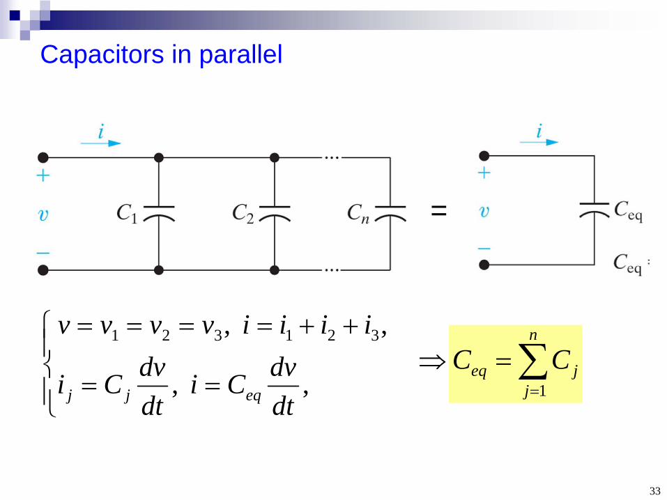
Capacitors in parallel
n
jjeq CC
1
=
, ,
, , 321321
dtdvCi
dtdvCi
iiiivvvv
eqjj
34
Section 6.4, 6.5 Mutual Inductance
1. Physics2. i-v relation and dot convention3. Energy
35
Fundamentals
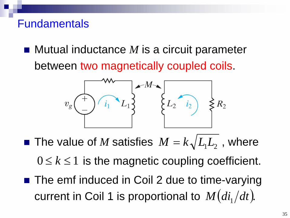
Mutual inductance M is a circuit parameter between two magnetically coupled coils.
The value of M satisfies , where
is the magnetic coupling coefficient.
The emf induced in Coil 2 due to time-varying current in Coil 1 is proportional to
21LLkM
10 k
.1 dtdiM
36
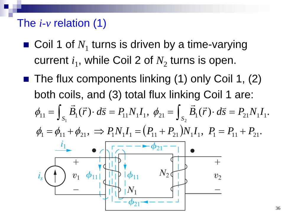
Coil 1 of N1 turns is driven by a time-varying current i1 , while Coil 2 of N2 turns is open.
The flux components linking (1) only Coil 1, (2) both coils, and (3) total flux linking Coil 1 are:
The i-v relation (1)
.)( ,)( 1121 1211111 11121
INPsdrBINPsdrBSS
. , , 2111111211111121111 PPPINPPINP
37
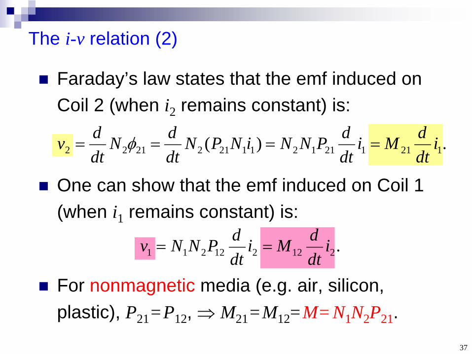
Faraday’s law states that the emf induced on Coil 2 (when i2 remains constant) is:
The i-v relation (2)
.)( 12112112112122122 idtdMi
dtdPNNiNPN
dtdN
dtdv
One can show that the emf induced on Coil 1 (when i1 remains constant) is:
.212212211 idtdMi
dtdPNNv
For nonmagnetic media (e.g. air, silicon, plastic), P21 =P12 , M21 =M12 =M= N1 N2 P21 .
38
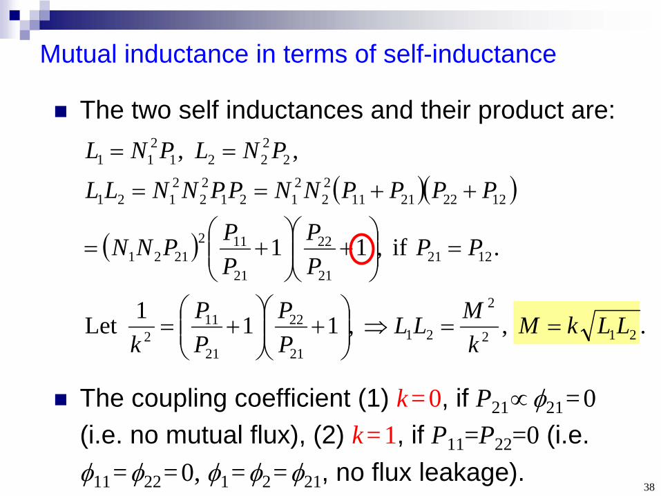
Mutual inductance in terms of self-inductance
. , ,111Let
. if ,11
, ,
212
2
2121
22
21
112
122121
22
21
1122121
1222211122
2121
22
2121
22221
211
LLkMkMLL
PP
PP
k
PPPP
PPPNN
PPPPNNPPNNLL
PNLPNL
The two self inductances and their product are:
The coupling coefficient (1) k=0, if P21 21 =0 (i.e. no mutual flux), (2) k=1, if P11 =P22 =0 (i.e. 11 =22 =0, 1 =2 =21 , no flux leakage).
39
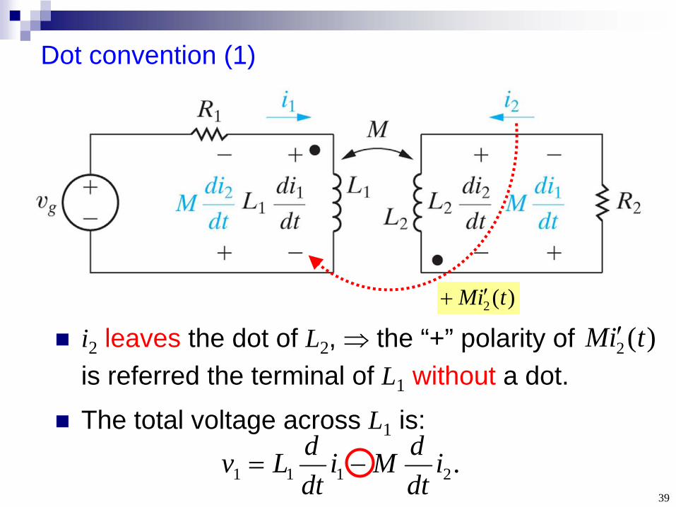
Dot convention (1)
.2111 idtdMi
dtdLv
i2 leaves the dot of L2 , the “+” polarity of is referred the terminal of L1 without a dot.
The total voltage across L1 is:
)(2 tiM )(2 tiM

40
Dot convention (2)
i1 enters the dot of L1 , the “+” polarity of is referred the terminal of L2 with a dot.
The total voltage across L2 is:
)(1 tiM
)(1 tiM
.1222 idtdMi
dtdLv

41
Example 6.6: Write a mesh current equation
0)()H 8())( 5())( 20()H 4( 21211 iidtdiiiii
dtd
gg
Self-inductance,passive sign convention
Mutual-inductance,ig i2 enters the dot of 16-H inductor

42
Example 6.6: Steady-state analysis
In steady state (t ), inductors are short, the 3 resistors are in parallel (Req =3.75 ).
Let v2 =0. (1) v1 = (16A)(3.75 )=60 V. (2) i12 = (60V)/(5) =12A, i1 = (16-12)=4 A (not zero!). (3) i1'2 = (60V)/(20)=3 A, i22' =(12+3)=15 A.
1 2 1'
2'
12 A 3 A60 V
4 A

43
Energy of mutual inductance (1)
Assume i1 , i2 =0 initially. Fix i2 =0 while increasing i1 from 0 to some constant I1 . The energy stored in L1 becomes:
.21 2
110 11111 ILdiiLW
I
44
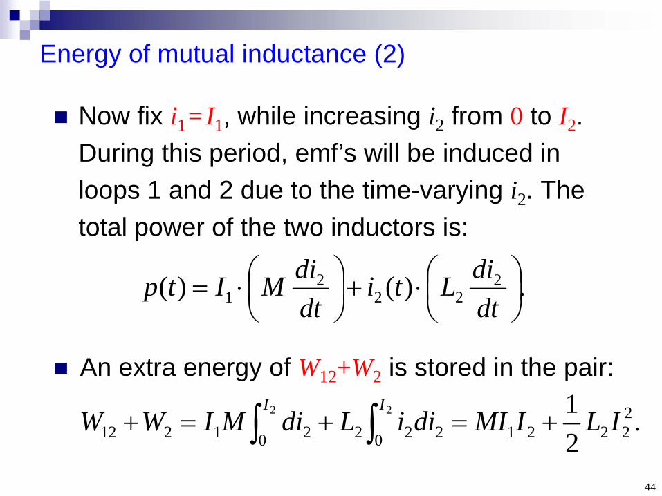
Energy of mutual inductance (2)
Now fix i1 = I1 , while increasing i2 from 0 to I2 . During this period, emf’s will be induced in loops 1 and 2 due to the time-varying i2 . The total power of the two inductors is:
.21 2
22210 2220 2121222 ILIMIdiiLdiMIWW
II
.)()( 222
21
dtdiLti
dtdiMItp
An extra energy of W12 +W2 is stored in the pair:

45
Energy of mutual inductance (3)
The entire process contributes to a total energy
for the two-inductor system.
Wtot only depends on the final currents I1 , I2
[independent of the time evolution of i1 (t), i2 (t)].
22221
211 2
121 ILIMIILWtot

46
Why the i-v relation of an inductor is
Why the i-v relation of a capacitor is
Why the energies stored in an inductor and a capacitor are:
Key points
?dtdiLv
?dtdvCi
ly?respective ,21,
21 22 CvLiw


![A Molecular Cage-Based [2]Rotaxane That Behaves as a ...ntur.lib.ntu.edu.tw/bitstream/246246/169681/1/499.pdf · A Molecular Cage-Based [2]Rotaxane That Behaves as a Molecular Muscle](https://img.dokumen.tips/doc/110x75/5b24c0b47f8b9a3b0f8b519a/a-molecular-cage-based-2rotaxane-that-behaves-as-a-nturlibntuedutwbitstream2462461696811499pdf.jpg)