Embed Size (px)
Citation preview
Chapter 6: Datapath and Control6-1
CPSC 352
Chapter 6: Datapath and Control

Chapter 6: Datapath and Control6-2
CPSC 352
Chapter Contents6.1 Basics of the Microarchitecture6.2 A Microarchitecture for the ARC6.3 Hardwired Control6.4 Case Study: The VHDL Hardware Description Language
Chapter 6: Datapath and Control6-3
CPSC 352
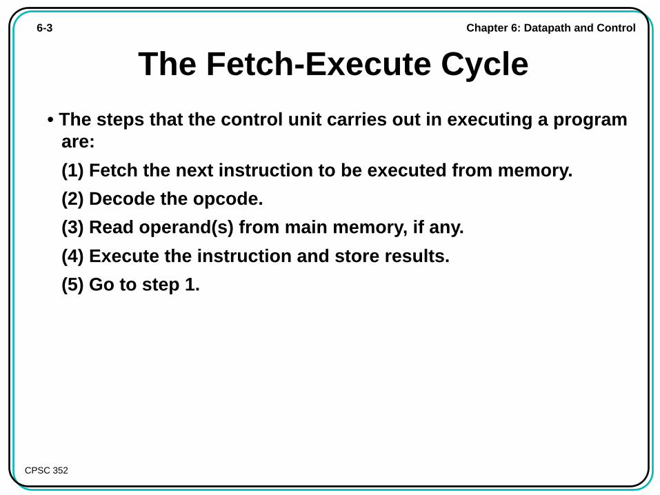
The Fetch-Execute Cycle
• The steps that the control unit carries out in executing a programare:
(1) Fetch the next instruction to be executed from memory.
(2) Decode the opcode.
(3) Read operand(s) from main memory, if any.
(4) Execute the instruction and store results.
(5) Go to step 1.
Chapter 6: Datapath and Control6-4
CPSC 352
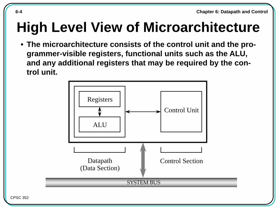
High Level View of Microarchitecture
Control Unit
Control Section
Registers
ALU
Datapath(Data Section)
SYSTEM BUS
• The microarchitecture consists of the control unit and the pro-grammer-visible registers, functional units such as the ALU,and any additional registers that may be required by the con-trol unit.
Chapter 6: Datapath and Control6-5
CPSC 352
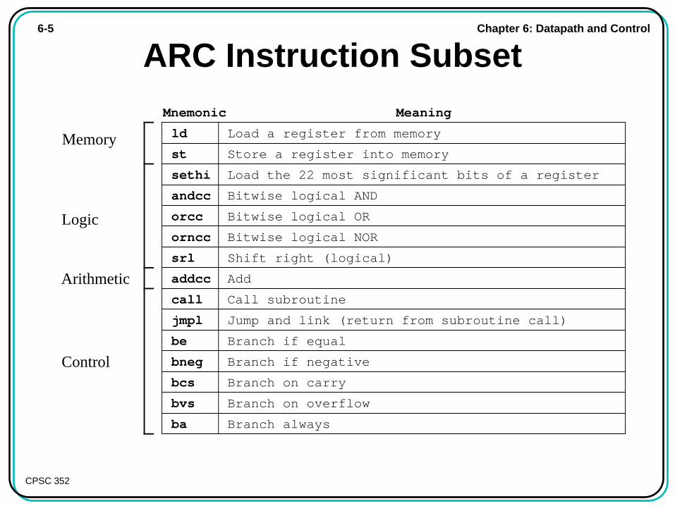
ARC Instruction Subset
ld Load a register from memory
Mnemonic Meaning
st
sethi
andcc
addcc
call
jmpl
be
orcc
orncc
Store a register into memory
Load the 22 most significant bits of a register
Bitwise logical AND
Add
Branch on overflow
Call subroutine
Jump and link (return from subroutine call)
Branch if equal
Bitwise logical OR
Bitwise logical NOR
bneg
bcs
Branch if negative
Branch on carry
srl Shift right (logical)
bvs
ba Branch always
Memory
Logic
Arithmetic
Control
Chapter 6: Datapath and Control6-6
CPSC 352
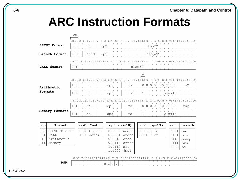
ARC Instruction Formats
op3 (op=10)
010000010001010010010110100110111000
addccandccorccornccsrljmpl
00010101011001111000
cond
bebcsbnegbvsba
branch
010100
op2
branchsethi
Inst.
00011011
op
SETHI/BranchCALLArithmeticMemory
Format
000000000100
ldst
op3 (op=11)
op
CALL format disp30
31 30 29 28 27 26 25 24 23 22 21 20 19 18 17 16 15 14 13 12 11 10 09 08 07 06 05 04 03 02 01 00
0 1
SETHI Format imm22
31 30 29 28 27 26 25 24 23 22 21 20 19 18 17 16 15 14 13 12 11 10 09 08 07 06 05 04 03 02 01 00
rd
disp220 cond
0 0
0 0Branch Format
op2
op2
31 30 29 28 27 26 25 24 23 22 21 20 19 18 17 16 15 14 13 12 11 10 09 08 07 06 05 04 03 02 01 00
rs11 op3
simm131 op3
1
Memory Formats1
rd
rd rs1
0
1
0 0 0 0 0 0 0 0 rs2
Arithmetic Formats
31 30 29 28 27 26 25 24 23 22 21 20 19 18 17 16 15 14 13 12 11 10 09 08 07 06 05 04 03 02 01 00
rs11 op3
simm131 op3
0
0
rd
rd rs1
0
1
0 0 0 0 0 0 0 0 rs2
i
PSR31 30 29 28 27 26 25 24 23 22 21 20 19 18 17 16 15 14 13 12 11 10 09 08 07 06 05 04 03 02 01 00
z v cn
Chapter 6: Datapath and Control6-7
CPSC 352
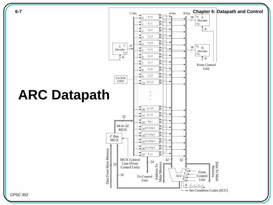
ARC Datapath
%r0A bus B busC bus
F1F2
ALU
32
32
4
%r1
64-to-32 MUX
C Bus MUX
n, z, v, c
F0
C Decoder %r5
%pc
%temp0
%r2
%r3
%r4
%r6
%r7
%r8
%r9
%r10
%r30
%r31
B Decoder
F3
6
c1
c37
37 38 b0
b37
6
A Decoder
38 a0
a37
6
Dat
a Fr
om M
ain
Mem
ory
MUX Control Line (From
Control Unit)
%temp1
%temp2
%temp3
%ir
Data T
o Main
Mem
ory
Add
ress
To
Mai
n M
emor
y
CLOCK UNIT
0
1
2
3
4
5
6
7
8
9
10
30
31
32
33
34
35
36
37
32
From Control
Unit
From Control Unit
Set Condition Codes (SCC)
32
32
.
.
.
To Control Unit
24
Chapter 6: Datapath and Control6-8
Principles of Computer Architecture by M. Murdocca and V. Heuring © 1999 M. Murdocca and V. Heuring
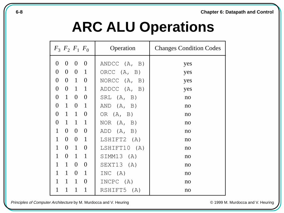
ARC ALU Operations
0011001100110011
0101010101010101
F1 F0
ANDCC (A, B)
ORCC (A, B)
NORCC (A, B)
ADDCC (A, B)
SRL (A, B)
AND (A, B)
OR (A, B)
NOR (A, B)
ADD (A, B)
LSHIFT2 (A)
LSHIFT10 (A)
SIMM13 (A)
SEXT13 (A)
INC (A)
INCPC (A)
RSHIFT5 (A)
Operation
0000111100001111
F2 Changes Condition Codes
yesyesyesyesnononononononononononono
0000000011111111
F3
Chapter 6: Datapath and Control6-9
Principles of Computer Architecture by M. Murdocca and V. Heuring © 1999 M. Murdocca and V. Heuring
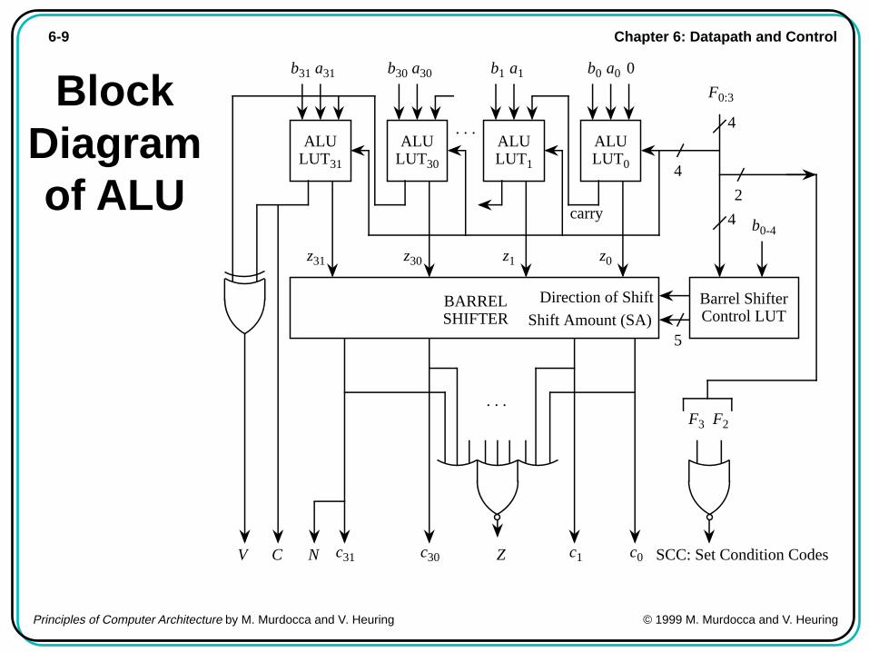
BlockDiagramof ALU
ALU LUT0
b0 a0
ALU LUT1
b1 a1
ALU LUT30
b30 a30
ALU LUT31
b31 a31
C c0c1c30c31
carry
BARREL SHIFTER
z0z1z30z31
. . .
F0:3
Barrel Shifter Control LUT
b0-4
Direction of Shift
Shift Amount (SA)5
NV Z
. . .
SCC: Set Condition Codes
F3 F2
0
2
4
4
4
Chapter 6: Datapath and Control6-10
Principles of Computer Architecture by M. Murdocca and V. Heuring © 1999 M. Murdocca and V. Heuring
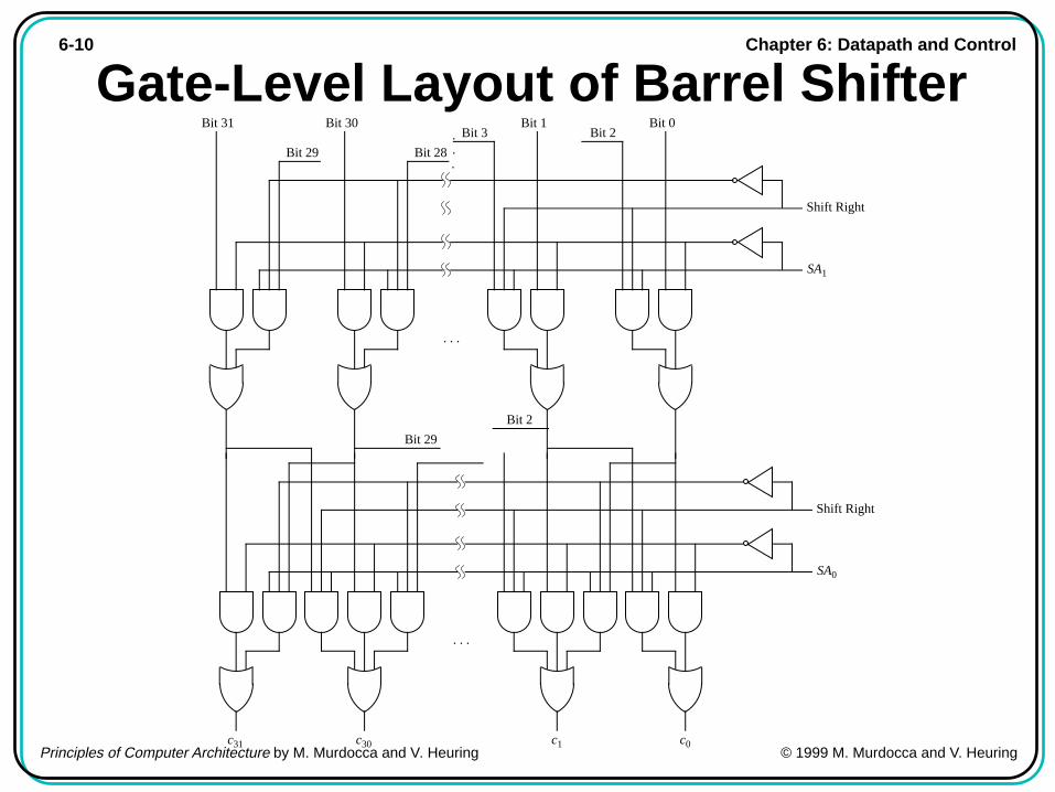
Gate-Level Layout of Barrel Shifter
c31 c30 c1 c0
SA0
. . .
Shift Right
SA1
. . .
Shift Right
.
.
.
Bit 31 Bit 30 Bit 1 Bit 0
Bit 29 Bit 28
Bit 3 Bit 2
Bit 29
Bit 2
Chapter 6: Datapath and Control6-11
Principles of Computer Architecture by M. Murdocca and V. Heuring © 1999 M. Murdocca and V. Heuring
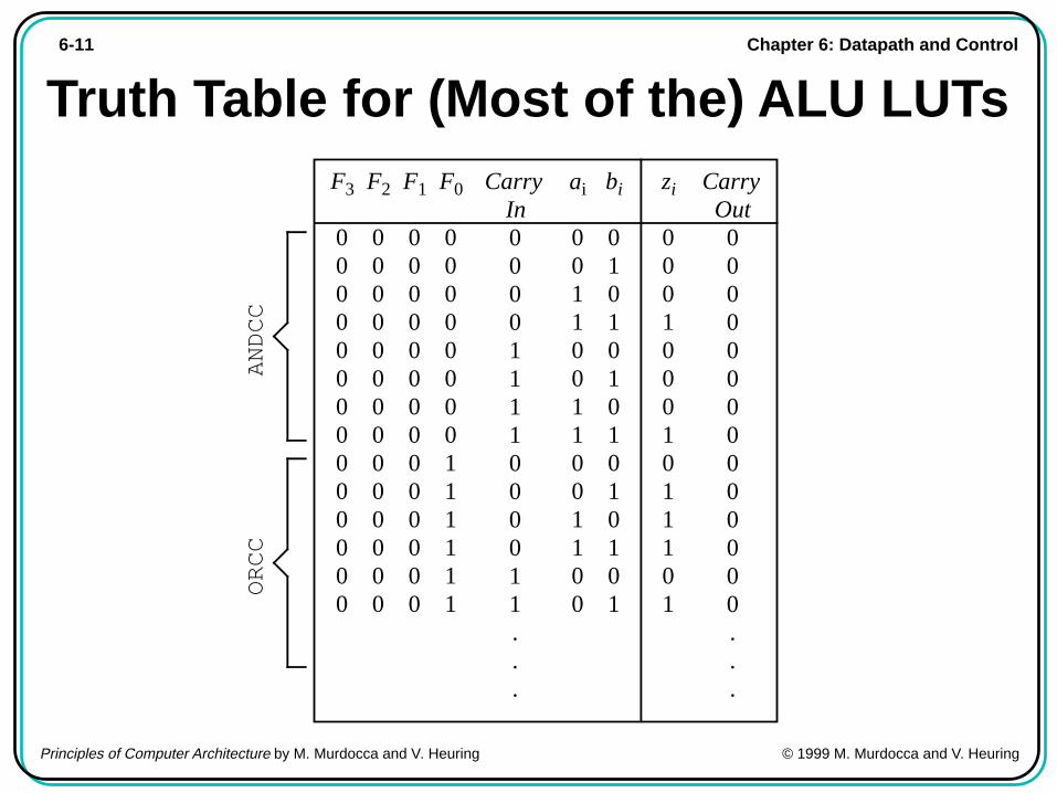
Truth Table for (Most of the) ALU LUTsF3
00000000000000
F2
00000000000000
F1
00000000000000
F0
00000000111111
Carry In00001111000011...
ai
00110011001100
bi
01010101010101
zi
00010001011101
Carry Out00000000000000...
ANDCC
ORCC

Chapter 6: Datapath and Control6-12
Principles of Computer Architecture by M. Murdocca and V. Heuring © 1999 M. Murdocca and V. Heuring
Design of Register %r1
CLKQD
C31
Write select (from c1 bit of C Decoder)
A31 B31
QD
C30
A30 B30
QD
C0
A0 B0
. . .
. . .A bus enable (from a1 bit of A Decoder)
B bus enable (from b1 bit of B Decoder)
. . .
Data inputs from C Bus
Data outputs to B BusData outputs to A Bus
Chapter 6: Datapath and Control6-13
Principles of Computer Architecture by M. Murdocca and V. Heuring © 1999 M. Murdocca and V. Heuring
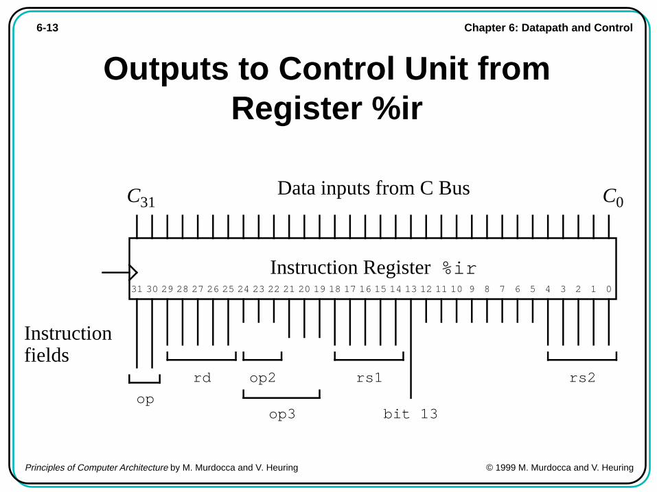
Outputs to Control Unit fromRegister %ir
Data inputs from C Bus
31 30 29 28 27 26 25 24 23 22 21 20 19 18 17 16 15 14 13 12 11 10 9 8 7 6 5 4 3 2 1 0
Instruction fields
C0C31
Instruction Register %ir
op
op2
op3
rd rs1 rs2
bit 13

Chapter 6: Datapath and Control6-14
Principles of Computer Architecture by M. Murdocca and V. Heuring © 1999 M. Murdocca and V. Heuring
Microarch-itecture ofthe ARC
32
A b
us
B b
us
C b
us
2048 word × 41 bit Control Store
CS Address MUX
Jump
Control branch
logic (CBL)
F1F2ALU
Microcode Instruction
Register (MIR)
CLOCK UNIT
41
11
11
MAIN MEMORYWRRD
Data Section (Datapath)
32
Address
Data In
00 = Next01 = Jump10 = Inst. Dec.
4
8
2
Decode
1 0 0
4
232 byte address space
32
3
Data Out
64-to-32 MUX
C Bus MUX
%psr
n, z, v, c
F0
Next
11
Control Store Address Incrementer (CSAI)
Acknowledge (ACK)
To C Decoder
%ir
C MUX
0, rd
Control Section
A MUX
0, rs1
To B Decoder
B MUX
0, rs2
F3
4
1
IR[30,31,19-24]
6 5
6
MIR C field
Sel
ect
MIR A field
MIR B field
6
6
5 6
Select
Select
Scratchpad
To A Decoder
rd rs2 rs1 ops
IR[13]
5 6
Set Condition Codes
%ir
RD
WRCA B JUMP ADDRALU COND
AMUX
BMUX
CMUX
Chapter 6: Datapath and Control6-15
Principles of Computer Architecture by M. Murdocca and V. Heuring © 1999 M. Murdocca and V. Heuring
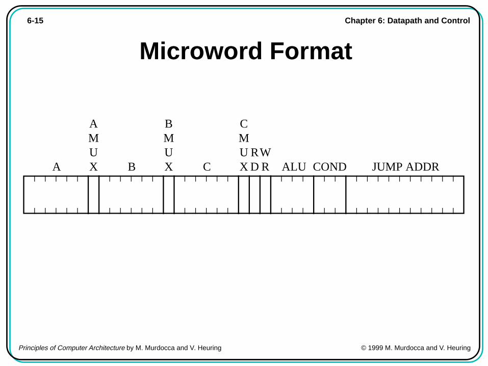
Microword Format
RD
WRCA B JUMP ADDRALU COND
AMUX
BMUX
CMUX
Chapter 6: Datapath and Control6-16
Principles of Computer Architecture by M. Murdocca and V. Heuring © 1999 M. Murdocca and V. Heuring
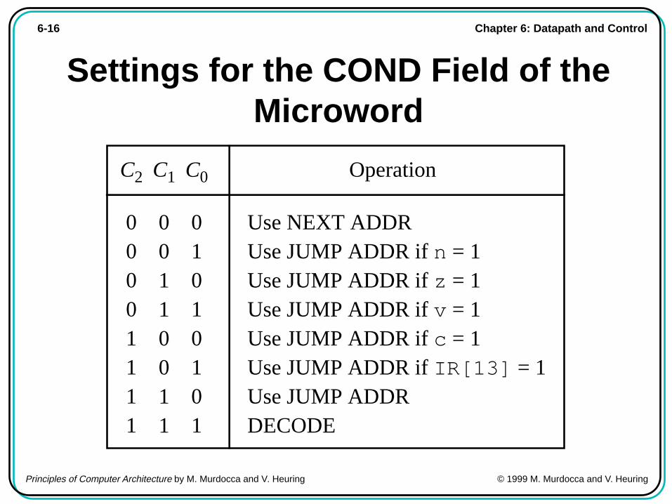
Settings for the COND Field of theMicroword
00110011
01010101
C1 C0
Use NEXT ADDRUse JUMP ADDR if n = 1Use JUMP ADDR if z = 1Use JUMP ADDR if v = 1Use JUMP ADDR if c = 1Use JUMP ADDR if IR[13] = 1Use JUMP ADDRDECODE
Operation
00001111
C2
Chapter 6: Datapath and Control6-17
Principles of Computer Architecture by M. Murdocca and V. Heuring © 1999 M. Murdocca and V. Heuring
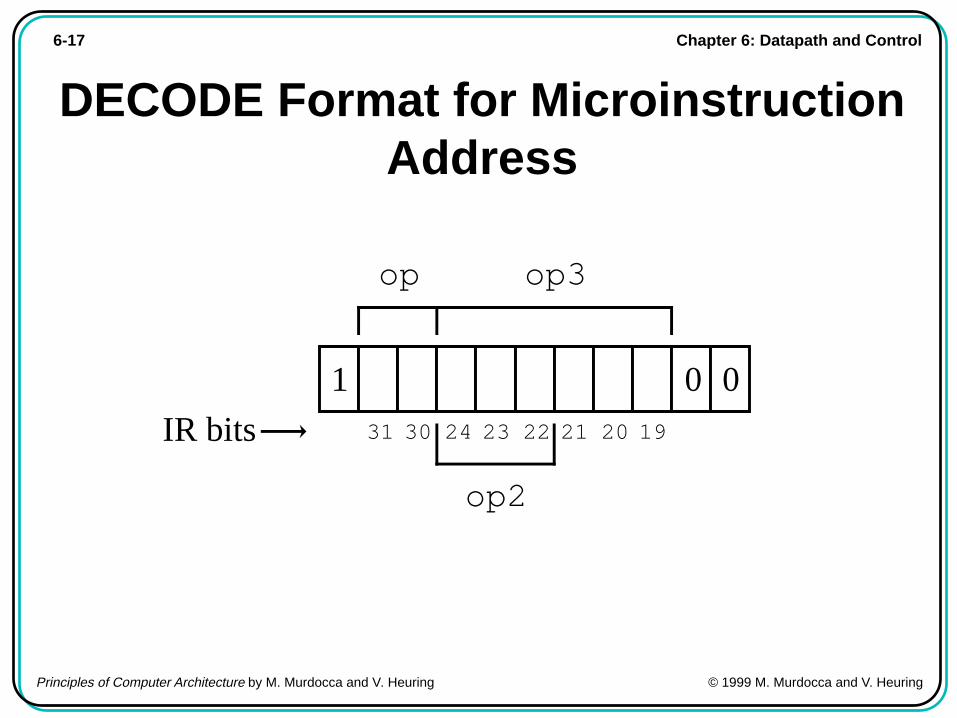
DECODE Format for MicroinstructionAddress
op
1 0 0
op2
op3
31 30 24 23 22 21 20 19IR bits
Chapter 6: Datapath and Control6-18
Principles of Computer Architecture by M. Murdocca and V. Heuring © 1999 M. Murdocca and V. Heuring
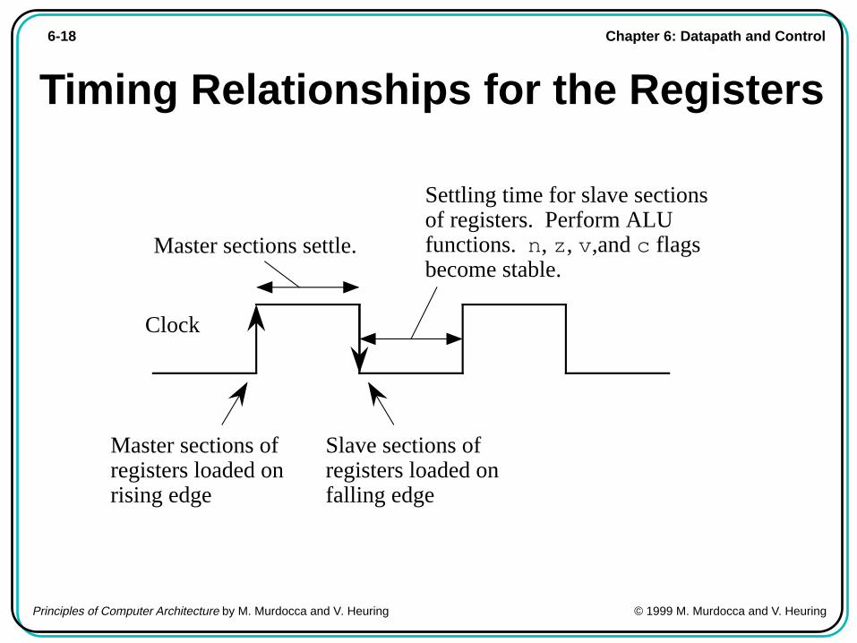
Timing Relationships for the Registers
Clock
Settling time for slave sections of registers. Perform ALU functions. n, z, v,and c flags become stable.
Master sections settle.
Master sections of registers loaded on rising edge
Slave sections of registers loaded on falling edge
Chapter 6: Datapath and Control6-19
Principles of Computer Architecture by M. Murdocca and V. Heuring © 1999 M. Murdocca and V. Heuring
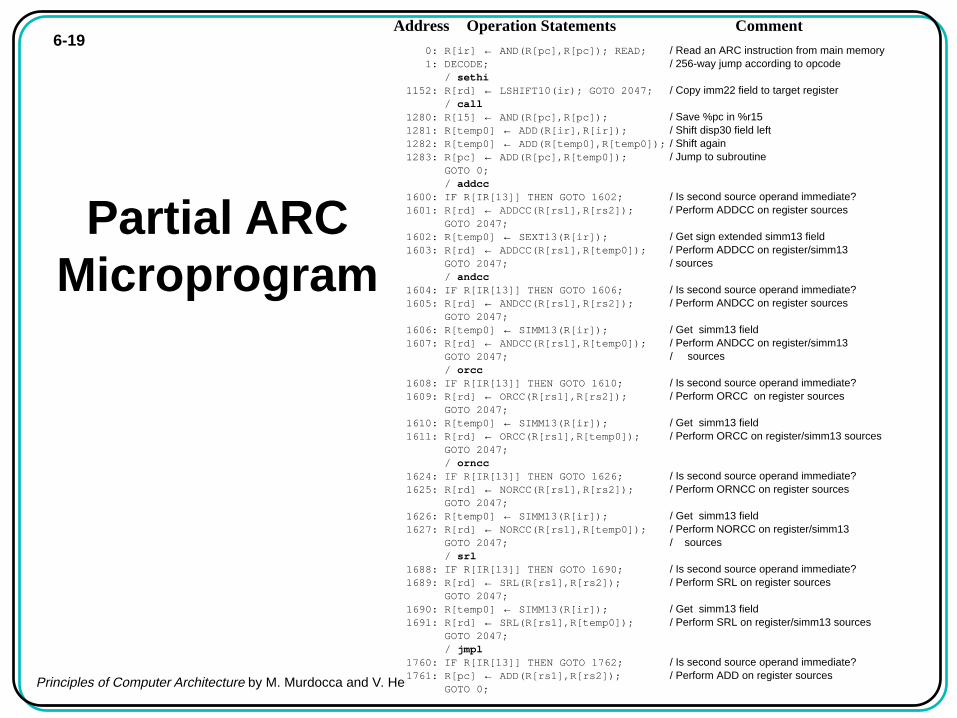
Partial ARCMicroprogram
0000: R[ir] ← AND(R[pc],R[pc]); READ; / Read an ARC instruction from main memory0001: DECODE; / 256-way jump according to opcode00// / sethi1152: R[rd] ← LSHIFT10(ir); GOTO 2047; / Copy imm22 field to target register00// / call1280: R[15] ← AND(R[pc],R[pc]); / Save %pc in %r151281: R[temp0] ← ADD(R[ir],R[ir]); / Shift disp30 field left1282: R[temp0] ← ADD(R[temp0],R[temp0]); / Shift again1283: R[pc] ← ADD(R[pc],R[temp0]); / Jump to subroutine GOTO 0; 0//0 / addcc1600: IF R[IR[13]] THEN GOTO 1602; / Is second source operand immediate?1601: R[rd] ← ADDCC(R[rs1],R[rs2]); / Perform ADDCC on register sources GOTO 2047; 1602: R[temp0] ← SEXT13(R[ir]); / Get sign extended simm13 field1603: R[rd] ← ADDCC(R[rs1],R[temp0]); / Perform ADDCC on register/simm13 GOTO 2047; / sources00// / andcc1604: IF R[IR[13]] THEN GOTO 1606; / Is second source operand immediate?1605: R[rd] ← ANDCC(R[rs1],R[rs2]); / Perform ANDCC on register sources GOTO 2047; 1606: R[temp0] ← SIMM13(R[ir]); / Get simm13 field1607: R[rd] ← ANDCC(R[rs1],R[temp0]); / Perform ANDCC on register/simm13 GOTO 2047; / sources 00// / orcc1608: IF R[IR[13]] THEN GOTO 1610; / Is second source operand immediate?1609: R[rd] ← ORCC(R[rs1],R[rs2]); / Perform ORCC on register sources GOTO 2047; 1610: R[temp0] ← SIMM13(R[ir]); / Get simm13 field1611: R[rd] ← ORCC(R[rs1],R[temp0]); / Perform ORCC on register/simm13 sources GOTO 2047;00// / orncc1624: IF R[IR[13]] THEN GOTO 1626; / Is second source operand immediate?1625: R[rd] ← NORCC(R[rs1],R[rs2]); / Perform ORNCC on register sources GOTO 2047; 1626: R[temp0] ← SIMM13(R[ir]); / Get simm13 field1627: R[rd] ← NORCC(R[rs1],R[temp0]); / Perform NORCC on register/simm13 GOTO 2047; / sources 00// / srl1688: IF R[IR[13]] THEN GOTO 1690; / Is second source operand immediate?1689: R[rd] ← SRL(R[rs1],R[rs2]); / Perform SRL on register sources GOTO 2047; 1690: R[temp0] ← SIMM13(R[ir]); / Get simm13 field1691: R[rd] ← SRL(R[rs1],R[temp0]); / Perform SRL on register/simm13 sources GOTO 2047;00// / jmpl1760: IF R[IR[13]] THEN GOTO 1762; / Is second source operand immediate?1761: R[pc] ← ADD(R[rs1],R[rs2]); / Perform ADD on register sources GOTO 0;
Address Operation Statements Comment

Chapter 6: Datapath and Control6-20
Principles of Computer Architecture by M. Murdocca and V. Heuring © 1999 M. Murdocca and V. Heuring
Partial ARCMicroprogram
(cont’)
1762: R[temp0] ← SEXT13(R[ir]); / Get sign extended simm13 field1763: R[pc] ← ADD(R[rs1],R[temp0]); / Perform ADD on register/simm13 sources GOTO 0;00// / ld1792: R[temp0] ← ADD(R[rs1],R[rs2]); / Compute source address IF R[IR[13]] THEN GOTO 1794; 1793: R[rd] ← AND(R[temp0],R[temp0]); / Place source address on A bus READ; GOTO 2047; 1794: R[temp0] ← SEXT13(R[ir]); / Get simm13 field for source address1795: R[temp0] ← ADD(R[rs1],R[temp0]); / Compute source address GOTO 1793;00// / st1808: R[temp0] ← ADD(R[rs1],R[rs2]); / Compute destination address IF R[IR[13]] THEN GOTO 1810; 1809: R[ir] ← RSHIFT5(R[ir]); GOTO 40; / Move rd field into position of rs2 field 40: R[ir] ← RSHIFT5(R[ir]); 41: R[ir] ← RSHIFT5(R[ir]); 42: R[ir] ← RSHIFT5(R[ir]); 43: R[ir] ← RSHIFT5(R[ir]); 44: R[0] ← AND(R[temp0], R[rs2]); / Place destination address on A bus and WRITE; GOTO 2047; / place operand on B bus1810: R[temp0] ← SEXT13(R[ir]); / Get simm13 field for destination address1811: R[temp0] ← ADD(R[rs1],R[temp0]); / Compute destination address GOTO 1809;00// / Branch instructions: ba, be, bcs, bvs, bneg1088: GOTO 2; / Decoding tree for branches 2: R[temp0] ← LSHIFT10(R[ir]); / Sign extend the 22 LSB’s of %temp0 3: R[temp0] ← RSHIFT5(R[temp0]); 4: R[temp0] ← RSHIFT5(R[temp0]); / bits. RSHIFT5 does sign extension. 5: R[ir] ← RSHIFT5(R[ir]); / Move COND field to IR[13] by 6: R[ir] ← RSHIFT5(R[ir]); 7: R[ir] ← RSHIFT5(R[ir]); 8: IF R[IR[13]] THEN GOTO 12; / Is it ba? R[ir] ← ADD(R[ir],R[ir]); 9: IF R[IR[13]] THEN GOTO 13; / Is it not be? R[ir] ← ADD(R[ir],R[ir]); 10: IF Z THEN GOTO 12; / Execute be R[ir] ← ADD(R[ir],R[ir]); 11: GOTO 2047; / Branch for be not taken 12: R[pc] ← ADD(R[pc],R[temp0]); / Branch is taken GOTO 0; 13: IF R[IR[13]] THEN GOTO 16; / Is it bcs? R[ir] ← ADD(R[ir],R[ir]); 14: IF C THEN GOTO 12; / Execute bcs 15: GOTO 2047; / Branch for bcs not taken 16: IF R[IR[13]] THEN GOTO 19; / Is it bvs? 17: IF N THEN GOTO 12; / Execute bneg 18: GOTO 2047; / Branch for bneg not taken 19: IF V THEN GOTO 12; / Execute bvs 20: GOTO 2047; / Branch for bvs not taken2047: R[pc] ← INCPC(R[pc]); GOTO 0; / Increment %pc and start over
/ by shifting left 10 bits, then right 10
/ applying RSHIFT5 three times. (The/ sign extension is inconsequential.)
/ by shifting to the right by 25 bits.
Chapter 6: Datapath and Control6-21
Principles of Computer Architecture by M. Murdocca and V. Heuring © 1999 M. Murdocca and V. Heuring
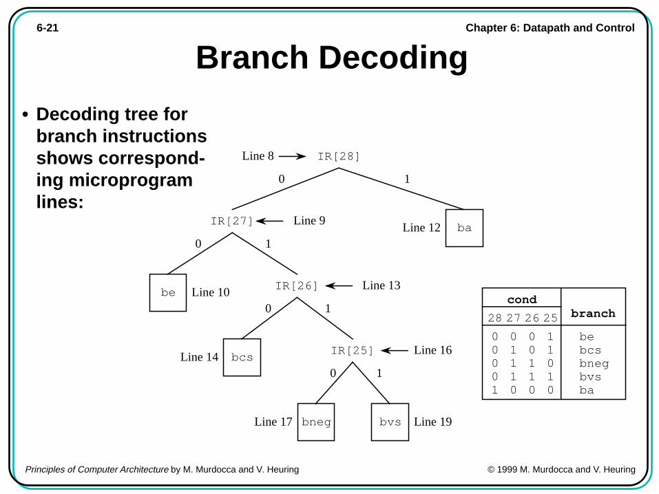
Branch Decoding
• Decoding tree forbranch instructionsshows correspond-ing microprogramlines:
bneg bvs
bcs
be
ba
IR[25]
IR[26]
IR[27]
IR[28]Line 8
Line 13
Line 16
Line 12
Line 19Line 17
Line 10
Line 14
condbranch
11010
25
bebcsbnegbvsba
00110
26
01110
27
00001
28
Line 9
0 1
0 1
0 1
0 1
Chapter 6: Datapath and Control6-22
Principles of Computer Architecture by M. Murdocca and V. Heuring © 1999 M. Murdocca and V. Heuring
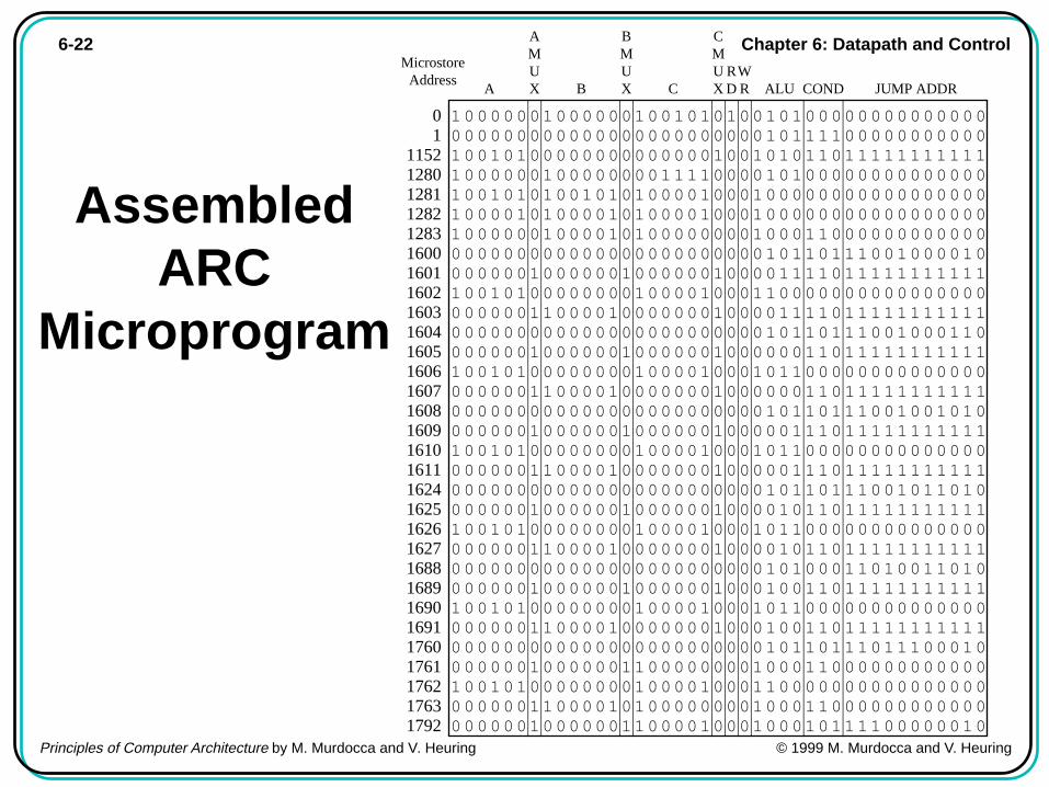
AssembledARC
Microprogram
RD
WRCA B JUMP ADDRALU COND
AMUX
BMUX
CMUX
1 000001 00000 001010100101000
11111111111
00 000000 00000 0000000001011110000000000011 010100 00000 000001001010110
00000000000
11521 000001 00000 0111100001010000000000000012801 010101 01010 0000100010000000000000000012811 000101 00010 0000100010000000000000000012821 000001 00010 00000000100011012830 000000 00000 0000000001011011100100001016000 000010 00001 00000100001111016011 010100 00000 0000100011000000000000000016020 000011 00010 00000100001111016030 000000 00000 0000000001011011100100011016040 000010 00001 00000100000011016051 010100 00000 0000100010110000000000000016060 000011 00010 00000100000011016070 000000 00000 0000000001011011100100101016080 000010 00001 00000100000111016091 010100 00000 0000100010110000000000000016100 000011 00010 000001000001110
0
16110 000000 00000 0000000001011011100101101016240 000010 00001 00000100001011016251 010100 00000 0000100010110000000000000016260 000011 00010 0000010000101116270 000000 00000 0000000001010001101001101016880 000010 00001 00000100010011016891 010100 00000 0000100010110000000000000016900 000011 00010 00000100010011016910 000000 00000 0000000001011011101110001017600 000010 00001 0000000010001100000000000017611 010100 00000 0000100011000000000000000017620 000011 00010 000000001000110000000000001763
000010 00001 000010001000101111000000101792
11111111111
11111111111
11111111111
00000000000
11111111111
11111111111
11111111111
11111111111
11111111111
11111111111
11111111111
Microstore Address
0
10001110010001000100010001001111
00000000000000000000000000000000
00000000000000000000000000000000
Chapter 6: Datapath and Control6-23
Principles of Computer Architecture by M. Murdocca and V. Heuring © 1999 M. Murdocca and V. Heuring
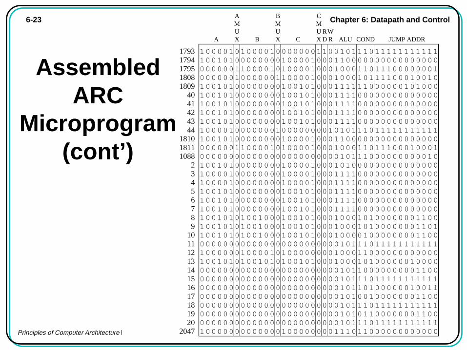
AssembledARC
Microprogram(cont’)
0 000000 000000 00000000101110201 000000 000001 0000000111011000000000002047
RD
WRCA B JUMP ADDRALU COND
AMUX
BMUX
CMUX
1 000101 000100 000011001011101111111111117931 010100 000001 000100011000000000000000017940 000011 000101 000100010001101110000000117950 000010 000011 000100010001011110001001018081 010100 000001 010100011111100000010100018091 010100 000001 0101000111100000000000000401 010100 000001 0101000111100000000000000411 010100 000001 0101000111100000000000000421 010100 000001 0101000111100000000000000431 000100 000010 0000001010111011111111111441 010100 000001 000100011000000000000000018100 000011 000101 000100010001101110001000118110 000000 000000 000000001011100000000001010881 010100 000001 000100010100000000000000021 000100 000001 000100011110000000000000031 000100 000001 000100011110000000000000041 010100 000001 010100011110000000000000051 010100 000001 010100011110000000000000061 010100 000001 010100011110000000000000071 010101 010001 010100010001010000000110081 010101 010001 010100010001010000000110191 010101 010001 0101000100001000000001100100 000000 000000 00000000101110
11111111111
111 000001 000101 0000000100011000000000000121 010101 010101 0101000100010100000010000130 000000 000000 0000000010110000000001100140 000000 000000 00000000101110150 000000 000000 0000000010110100000010011160 000000 000000 0000000010100100000001100170 000000 000000 00000000101110180 000000 000000 000000001010110000000110019
11111111111
11111111111
11111111111
00 0 00 0 0
0 0 00 0 00 0 00 0 00 0 00 0 00 0 00 0 00 0 00 0 00 0 00 0 00 0 00 0 00 0 00 0 00 0 00 0 00 0 00 0 0
0 0 00 0 00 0 00 0 00 0 00 0 00 0 00 0 00 0 00 0 00 0 0
Chapter 6: Datapath and Control6-24
Principles of Computer Architecture by M. Murdocca and V. Heuring © 1999 M. Murdocca and V. Heuring
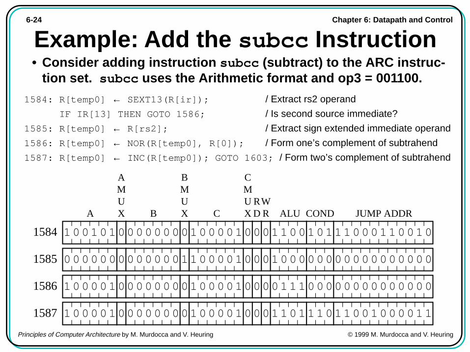
Example: Add the subcc Instruction• Consider adding instruction subcc (subtract) to the ARC instruc-
tion set. subcc uses the Arithmetic format and op3 = 001100.
1584: R[temp0] ← SEXT13(R[ir]); / Extract rs2 operand
IF IR[13] THEN GOTO 1586; / Is second source immediate?
1585: R[temp0] ← R[rs2]; / Extract sign extended immediate operand
1586: R[temp0] ← NOR(R[temp0], R[0]); / Form one’s complement of subtrahend
1587: R[temp0] ← INC(R[temp0]); GOTO 1603; / Form two’s complement of subtrahend
RD
WRCA B JUMP ADDRALU COND
AMUX
BMUX
CMUX
01010 000001 00010001100101110001100101584
00000 00001 00010001000000000000000001585
00010 00000 00010000111000000000000001586
00010 00000 00010001101110110010000111587
1 0
0 0 1
1 0 1
1 0 1
0 0 0
0 0 0
0 0 0
0 0 0

Chapter 6: Datapath and Control6-25
Principles of Computer Architecture by M. Murdocca and V. Heuring © 1999 M. Murdocca and V. Heuring
Branch Table• A branch table for trap handlers and interrupt service routines:
JUMP TO 2000
ContentsAddress Trap Handler...
.
.
.
60 Illegal instruction
JUMP TO 300064 Overflow
JUMP TO 360068 Underflow
JUMP TO 522472 Zerodivide
JUMP TO 418076 Disk
JUMP TO 536480 Printer
JUMP TO 590884 TTY
88 TimerJUMP TO 6048
Chapter 6: Datapath and Control6-26
Principles of Computer Architecture by M. Murdocca and V. Heuring © 1999 M. Murdocca and V. Heuring
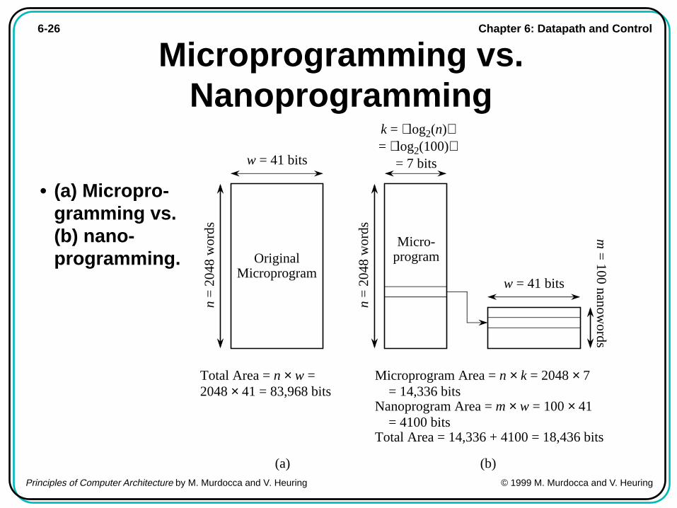
Microprogramming vs.Nanoprogramming
• (a) Micropro-gramming vs.(b) nano-programming. Original
Microprogram
w = 41 bits
n =
204
8 w
ords
k = log2(n) = log2(100)
= 7 bits
n =
204
8 w
ords
w = 41 bits
(a) (b)
m =
100 nanowords
Micro-program
Total Area = n × w = 2048 × 41 = 83,968 bits
Microprogram Area = n × k = 2048 × 7 = 14,336 bitsNanoprogram Area = m × w = 100 × 41 = 4100 bitsTotal Area = 14,336 + 4100 = 18,436 bits
Chapter 6: Datapath and Control6-27
Principles of Computer Architecture by M. Murdocca and V. Heuring © 1999 M. Murdocca and V. Heuring
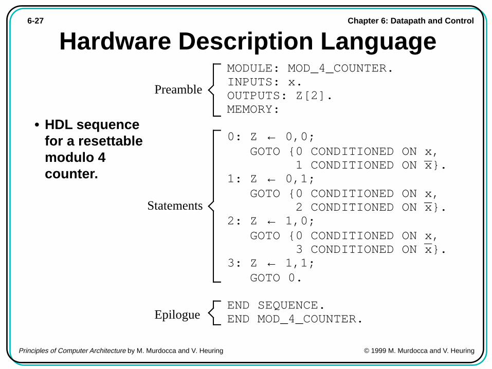
Hardware Description Language
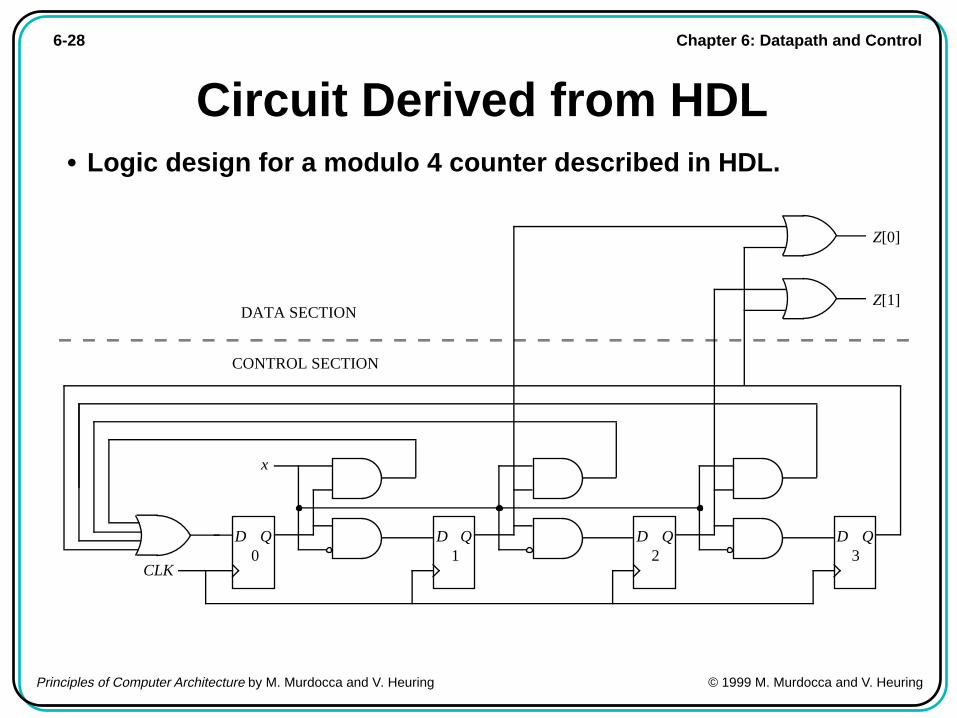
• HDL sequencefor a resettablemodulo 4counter.
MODULE: MOD_4_COUNTER.INPUTS: x.OUTPUTS: Z[2].MEMORY:
0: Z ← 0,0; GOTO {0 CONDITIONED ON x, 1 CONDITIONED ON x}.1: Z ← 0,1; GOTO {0 CONDITIONED ON x, 2 CONDITIONED ON x}.2: Z ← 1,0; GOTO {0 CONDITIONED ON x, 3 CONDITIONED ON x}.3: Z ← 1,1; GOTO 0.
END SEQUENCE.END MOD_4_COUNTER.
Preamble
Statements
Epilogue
Chapter 6: Datapath and Control6-28
Principles of Computer Architecture by M. Murdocca and V. Heuring © 1999 M. Murdocca and V. Heuring
Circuit Derived from HDL• Logic design for a modulo 4 counter described in HDL.
CLK
QD0
x
QD QD QD1 2 3
Z[1]
Z[0]
CONTROL SECTION
DATA SECTION

Chapter 6: Datapath and Control6-29
Principles of Computer Architecture by M. Murdocca and V. Heuring © 1999 M. Murdocca and V. Heuring
HDL for ARC
• HDL description of theARC control unit.
MODULE: ARC_CONTROL_UNIT.
INPUTS:
OUTPUTS: C, N, V, Z. ! These are set by the ALU
MEMORY: R[16][32], pc[32], ir[32], temp0[32], temp1[32], temp2[32],
temp3[32].
0: ir ← AND(pc, pc); Read ← 1; ! Instruction fetch ! Decode op field
1: GOTO {2 CONDITIONED ON ir[31]× ir[30], ! Branch/sethi format: op=00 4 CONDITIONED ON ir[31]× ir[30], ! Call format: op=01 8 CONDITIONED ON ir[31]× ir[30], ! Arithmetic format: op=10 10 CONDITIONED ON ir[31]× ir[30]}. ! Memory format: op=11 ! Decode op2 field
2: GOTO 19 CONDITIONED ON ir[24]. ! Goto 19 if Branch format
3: R[rd] ← ir[imm22]; ! sethi GOTO 20.
4: R[15] ← AND(pc, pc). ! call: save pc in register 155: temp0 ← ADD(ir, ir). ! Shift disp30 field left6: temp0 ← ADD(ir, ir). ! Shift again7: pc ← ADD(pc, temp0); GOTO 0. ! Jump to subroutine ! Get second source operand into temp0 for Arithmetic format
8: temp0 ← { SEXT13(ir) CONDITIONED ON ir[13]× NOR(ir[19:22]), ! addcc R[rs2] CONDITIONED ON ir[13]× NOR(ir[19:22]), ! addcc SIMM13(ir) CONDITIONED ON ir[13]× OR(ir[19:22]), ! Remaining R[rs2] CONDITIONED ON ir[13]× OR(ir[19:22])}. ! Arithmetic instructions ! Decode op3 field for Arithmetic format
9: R[rd] ← { ADDCC(R[rs1], temp0) CONDITIONED ON XNOR(IR[19:24], 010000), ! addcc
ANDCC(R[rs1], temp0) CONDITIONED ON XNOR(IR[19:24], 010001), ! andcc
ORCC(R[rs1], temp0) CONDITIONED ON XNOR(IR[19:24], 010010), ! orcc
NORCC(R[rs1], temp0) CONDITIONED ON XNOR(IR[19:24], 010110), ! orncc
SRL(R[rs1], temp0) CONDITIONED ON XNOR(IR[19:24], 100110), ! srl
ADD(R[rs1], temp0) CONDITIONED ON XNOR(IR[19:24], 111000)}; ! jmpl
GOTO 20.
! Get second source operand into temp0 for Memory format
10: temp0 ← {SEXT13(ir) CONDITIONED ON ir[13], R[rs2] CONDITIONED ON ir[13]}.
11: temp0 ← ADD(R[rs1], temp0). ! Decode op3 field for Memory format
GOTO {12 CONDITIONED ON ir[21], ! ld
13 CONDITIONED ON ir[21]}. ! st
12: R[rd] ← AND(temp0, temp0); Read ← 1; GOTO 20.13: ir ← RSHIFT5(ir).

Chapter 6: Datapath and Control6-30
Principles of Computer Architecture by M. Murdocca and V. Heuring © 1999 M. Murdocca and V. Heuring
HDL for ARC(cont’)
14: ir ← RSHIFT5(ir).15: ir ← RSHIFT5(ir).16: ir ← RSHIFT5(ir).17: ir ← RSHIFT5(ir).18: r0 ← AND(temp0, R[rs2]); Write ← 1; GOTO 20.19: pc ← { ! Branch instructions ADD(pc, temp0) CONDITIONED ON ir[28] + ir[28]× ir[27]× Z + ir[28]× ir[27]× ir[26]× C + ir[28]× ir[27]× ir[26]× ir[25]× N + ir[28]× ir[27]× ir[26]× ir[25]× V, INCPC(pc) CONDITIONED ON ir[28]× ir[27]× Z + ir[28]× ir[27]× ir[26]× C + ir[28]× ir[27]× ir[26]× ir[25]× N + ir[28]× ir[27]× ir[26]× ir[25]× V}; GOTO 0.
20: pc ← INCPC(pc); GOTO 0.END SEQUENCE.
END ARC_CONTROL_UNIT.
Chapter 6: Datapath and Control6-31
Principles of Computer Architecture by M. Murdocca and V. Heuring © 1999 M. Murdocca and V. Heuring
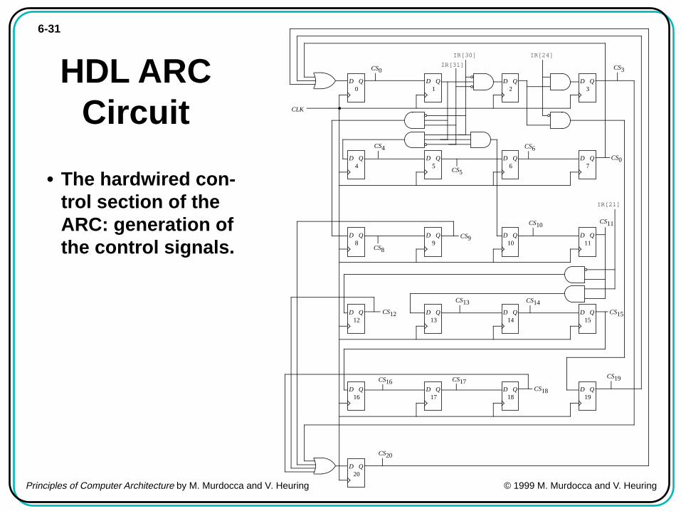
HDL ARCCircuit
• The hardwired con-trol section of theARC: generation ofthe control signals.
CLK
QD0
QD1
QD2
QD3
QD4
QD5
QD6
QD7
QD8
QD9
QD10
QD11
QD12
QD13
QD14
QD15
QD16
QD17
QD18
QD19
IR[31]
IR[30] IR[24]
IR[21]
QD20
CS0 CS3
CS4
CS5
CS6
CS0
CS8
CS9
CS10CS11
CS12
CS13 CS14
CS15
CS16 CS17CS18
CS19
CS20

Chapter 6: Datapath and Control6-32
Principles of Computer Architecture by M. Murdocca and V. Heuring © 1999 M. Murdocca and V. Heuring
• Hardwired con-trol section ofthe ARC: sig-nals from thedata section ofthe control unitto thedatapath.
AMUXCS9
CS11
WriteCS18
CMUXCS3
CS9CS12
ReadCS0
CS12
BMUX
CS18IR[13]
CS10
CS8
IR[1
9] IR[2
2]IR
[20]
IR[2
1]ALU[3]
CS9
IR[19]IR[20]
IR[24]
IR[23]
IR[22]IR[21]
CS20CS19
CS8
CS5CS6CS7
CS16CS14
CS15
CS17
CS11
CS13
ALU[2]
CS20CS18
CS4
CS10
CS12
CS16
CS14
CS15
CS1
CS13CS17
CS2
CS3
CS8
IR[13]
IR[19]IR[20]
IR[22]IR[21]
CS9
IR[2
4]IR
[23]
IR[19]IR[20]IR
[22]
IR[21]
CS19IR[28]
IR[28]IR[27]
IR[26]IR[25]
C
IR[28]IR[27]
IR[26]IR[25] N
IR[28]IR[27]
IR[26]C
IR[28]
IR[27]Z
CS2CS3IR[24]
ALU[0]
ALU[1]
CS20CS16
CS14CS15
CS13
CS17
IR[20]IR[21]
CS19
CS8
IR[13]IR[19]
IR[22]
IR[20]
IR[21]
CS9
IR[1
9]IR
[22]
IR[24]IR[23]
CS4 CS1
CS0
IR[13]CS8
IR[22]IR[21]
IR[19]
IR[23]
B[5]
B[2]
B[3]
B[4]
B[0]
B[1]
C[3]
C[4]
C[5]
IR[13]
IR[13]
A[1]
A[3]
A[4]
0
0
0
A[0]
CS5CS6
CS16CS14
CS15
CS17
CS13
CS12CS8
CS10
CS18
A[2]
A[5]CS4
CS0
CS20CS19
CS7
C[0]
C[1]
C[2]
HDL ARC Circuit (cont’)

Chapter 6: Datapath and Control6-33
Principles of Computer Architecture by M. Murdocca and V. Heuring © 1999 M. Murdocca and V. Heuring
Case Study: The VHDL Hardware De-scription Language
• The majority function. a) truth table, b) AND-OR implementation,c) black box representation.
B CA
b) c)a)
F
MajorityFunction
00110011
01010101
B C
00001111
A
00010111
F
01234567
MintermIndex
F
A B C
A B C
A B C
A B C
A B C
Chapter 6: Datapath and Control6-34
Principles of Computer Architecture by M. Murdocca and V. Heuring © 1999 M. Murdocca and V. Heuring
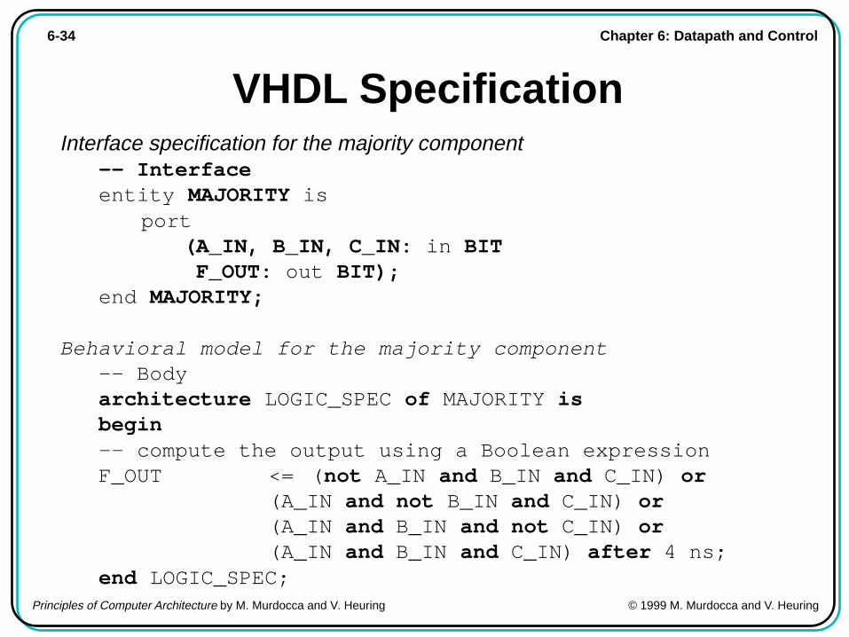
VHDL SpecificationInterface specification for the majority component
-- Interfaceentity MAJORITY is
port(A_IN, B_IN, C_IN: in BIT F_OUT: out BIT);
end MAJORITY;
Behavioral model for the majority component-- Bodyarchitecture LOGIC_SPEC of MAJORITY isbegin-- compute the output using a Boolean expressionF_OUT <= (not A_IN and B_IN and C_IN) or
(A_IN and not B_IN and C_IN) or(A_IN and B_IN and not C_IN) or(A_IN and B_IN and C_IN) after 4 ns;
end LOGIC_SPEC;

Chapter 6: Datapath and Control6-35
Principles of Computer Architecture by M. Murdocca and V. Heuring © 1999 M. Murdocca and V. Heuring
VHDL Specification (cont’)-- Package declaration, in library WORKpackage LOGIC_GATES iscomponent AND3
port (A, B, C : in BIT; X : out BIT);end component ;component OR4
port (A, B, C, D : in BIT; X : out BIT);end component ;component NOT1
port (A : in BIT; X : out BIT);end component ;
-- Interfaceentity MAJORITY is
port(A_IN, B_IN, C_IN: in BIT F_OUT: out BIT);
end MAJORITY;
Chapter 6: Datapath and Control6-36
Principles of Computer Architecture by M. Murdocca and V. Heuring © 1999 M. Murdocca and V. Heuring
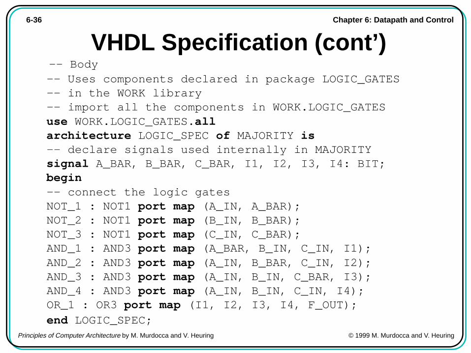
VHDL Specification (cont’) -- Body
-- Uses components declared in package LOGIC_GATES-- in the WORK library-- import all the components in WORK.LOGIC_GATESuse WORK.LOGIC_GATES.allarchitecture LOGIC_SPEC of MAJORITY is-- declare signals used internally in MAJORITYsignal A_BAR, B_BAR, C_BAR, I1, I2, I3, I4: BIT;begin-- connect the logic gatesNOT_1 : NOT1 port map (A_IN, A_BAR);NOT_2 : NOT1 port map (B_IN, B_BAR);NOT_3 : NOT1 port map (C_IN, C_BAR);AND_1 : AND3 port map (A_BAR, B_IN, C_IN, I1);AND_2 : AND3 port map (A_IN, B_BAR, C_IN, I2);AND_3 : AND3 port map (A_IN, B_IN, C_BAR, I3);AND_4 : AND3 port map (A_IN, B_IN, C_IN, I4);OR_1 : OR3 port map (I1, I2, I3, I4, F_OUT);end LOGIC_SPEC;