Embed Size (px)
Citation preview
All contents are Copyright © 1992–2012 Cisco Systems, Inc. All rights reserved. This document is Cisco Public Information. Page 1 of 32
CCNA Security
Chapter 4 Lab A: Configuring CBAC and Zone-Based Firewalls
Topology
Note: ISR G2 devices have Gigabit Ethernet interfaces instead of Fast Ethernet Interfaces.
IP Addressing Table
Device
Interface IP Address Subnet Mask Default Gateway
Switch Port
R1 Fa0/1 192.168.1.1 255.255.255.0 N/A S1 Fa0/5
S0/0/0 (DCE) 10.1.1.1 255.255.255.252 N/A N/A
R2 S0/0/0 10.1.1.2 255.255.255.252 N/A N/A
S0/0/1 (DCE) 10.2.2.2 255.255.255.252 N/A N/A
R3 Fa0/1 192.168.3.1 255.255.255.0 N/A S3 Fa0/5
S0/0/1 10.2.2.1 255.255.255.252 N/A N/A
PC-A NIC 192.168.1.3 255.255.255.0 192.168.1.1 S1 Fa0/6
PC-C NIC 192.168.3.3 255.255.255.0 192.168.3.1 S3 Fa0/18
Objectives
Part 1: Basic Router Configuration
Configure host names, interface IP addresses, and access passwords.

CCNA Security
All contents are Copyright © 1992–2012 Cisco Systems, Inc. All rights reserved. This document is Cisco Public Information. Page 2 of 32
Configure the EIGRP dynamic routing protocol.
Use the Nmap port scanner to test for router vulnerabilities
Part 2: Configuring a Context-Based Access Control (CBAC) Firewall
Configure CBAC using AutoSecure.
Examine the resulting CBAC configuration.
Verify the firewall functionality.
Part 3: Configuring a Zone-Based Policy Firewall (ZBF, ZPF or ZFW)
Use CCP to configure a zone-based policy firewall.
Examine the resulting CBAC configuration.
Use CCP Monitor to verify configuration.
Background
The most basic form of a Cisco IOS firewall uses access control lists (ACLs) with filtering IP traffic and monitoring established traffic patterns. This is referred to as a traditional Cisco IOS firewall. In more recent Cisco IOS versions, this approach has evolved into a method called context-based access control (CBAC) or Inspect/CBAC, which is based on Stateful Packet Inspection (SPI). CBAC makes creating firewalls easier and gives the administrator greater control over various types of application traffic originating from inside and outside of the protected network. When Cisco IOS AutoSecure is run, it prompts to create a CBAC firewall and generates a basic configuration. For simple networks with a single inside and outside interface, CBAC is easier to configure than traditional Cisco IOS firewalls. Configurations with multiple interfaces and DMZ requirements can become complex and difficult to manage using CBAC.
The current method used with CCP for securing routers is called a zone-based policy firewall (may be abbreviated as ZBF, ZPF or ZFW). A zone-based policy firewall provides the same type of functionality as CBAC, but is better suited for multiple interfaces that have similar or varying security requirements. While AutoSecure generates a CBAC firewall, CCP generates a ZBF firewall by default.
In this lab, you build a multi-router network and configure the routers and hosts. You use AutoSecure to configure a CBAC firewall and CCP to configure a zone-based policy firewall.
Note: The router commands and output in this lab are from a Cisco 1841 with Cisco IOS Release 12.4(20)T (Advanced IP image). Other routers and Cisco IOS versions can be used. See the Router Interface Summary table at the end of the lab to determine which interface identifiers to use based on the equipment in the lab. Depending on the router model and Cisco IOS version, the commands available and output produced might vary from what is shown in this lab.
Note: Make sure that the routers and the switches have been erased and have no startup configurations.
Required Resources
3 routers (Cisco 1841 with Cisco IOS Release 12.4(20)T1 or comparable)
2 switches (Cisco 2960 or comparable)
PC-A: Windows XP, Vista or Windows 7
PC-C: Windows XP, Vista or Windows 7 with CCP 2.5
Serial and Ethernet cables as shown in the topology
Rollover cables to configure the routers via the console
CCP Notes:
Refer to Chp 00 Lab A for instructions on how to install CCP. Hardware/software recommendations for CCP include Windows XP, Vista, or Windows 7 with Java version 1.6.0_11 up to 1.6.0_21, Internet Explorer 6.0 or above and Flash Player Version 10.0.12.36 and later.
CCNA Security
All contents are Copyright © 1992–2012 Cisco Systems, Inc. All rights reserved. This document is Cisco Public Information. Page 3 of 32
If the PC on which CCP is installed is running Windows Vista or 7, it may be necessary to right-click on the CCP icon or menu item, and choose Run as administrator.
In order to run CCP, it may be necessary to temporarily disable antivirus programs and O/S firewalls. Make sure that all pop-up blockers are turned off in the browser.
Part 1: Basic Router Configuration
In Part 1 of this lab, you set up the network topology and configure basic settings, such as the interface IP addresses, dynamic routing, device access, and passwords.
Note: All tasks should be performed on routers R1, R2 and R3. The procedure for R1 is shown here as an example.
Task 1: Configure Basic Router Settings
Step 1: Cable the network as shown in the topology.
Attach the devices shown in the topology diagram, and cable as necessary.
Step 2: Configure basic settings for each router.
a. Configure host names as shown in the topology.
b. Configure the interface IP addresses as shown in the IP addressing table.
c. Configure a clock rate for the serial router interfaces with a DCE serial cable attached.
R1(config)# interface S0/0/0
R1(config-if)# clock rate 64000
Step 3: Disable DNS lookup.
To prevent the router from attempting to translate incorrectly entered commands, disable DNS lookup.
R1(config)# no ip domain-lookup
Step 4: Configure the EIGRP routing protocol on R1, R2, and R3.
a. On R1, use the following commands.
R1(config)# router eigrp 101
R1(config-router)# network 192.168.1.0 0.0.0.255
R1(config-router)# network 10.1.1.0 0.0.0.3
R1(config-router)# no auto-summary
b. On R2, use the following commands.
R2(config)# router eigrp 101
R2(config-router)# network 10.1.1.0 0.0.0.3
R2(config-router)# network 10.2.2.0 0.0.0.3
R2(config-router)# no auto-summary
c. On R3, use the following commands.
R3(config)# router eigrp 101
R3(config-router)# network 192.168.3.0 0.0.0.255
R3(config-router)# network 10.2.2.0 0.0.0.3
R3(config-router)# no auto-summary
CCNA Security
All contents are Copyright © 1992–2012 Cisco Systems, Inc. All rights reserved. This document is Cisco Public Information. Page 4 of 32
Step 5: Configure PC host IP settings.
a. Configure a static IP address, subnet mask, and default gateway for PC-A, as shown in the IP addressing table.
b. Configure a static IP address, subnet mask, and default gateway for PC-C, as shown in the IP addressing table.
Step 6: Verify basic network connectivity.
a. Ping from R1 to R3.
Were the results successful? _____
If the pings are not successful, troubleshoot the basic device configurations before continuing.
b. Ping from PC-A on the R1 LAN to PC-C on the R3 LAN.
Were the results successful? _____
If the pings are not successful, troubleshoot the basic device configurations before continuing.
Note: If you can ping from PC-A to PC-C, you have demonstrated that the EIGRP routing protocol is configured and functioning correctly. If you cannot ping but the device interfaces are up and IP addresses are correct, use the show run and show ip route commands to help identify routing protocol-related
problems.
Step 7: Configure a minimum password length.
Note: Passwords in this lab are set to a minimum of 10 characters but are relatively simple for the benefit of performing the lab. More complex passwords are recommended in a production network.
Use the security passwords command to set a minimum password length of 10 characters.
R1(config)# security passwords min-length 10
Step 8: Configure basic console, auxiliary port, and vty lines.
a. Configure a console password and enable login for router R1. For additional security, the exec-
timeout command causes the line to log out after 5 minutes of inactivity. The logging
synchronous command prevents console messages from interrupting command entry.
Note: To avoid repetitive logins during this lab, the exec-timeout can be set to 0 0, which prevents it
from expiring. However, this is not considered a good security practice.
R1(config)# line console 0
R1(config-line)# password ciscoconpass
R1(config-line)# exec-timeout 5 0
R1(config-line)# login
R1(config-line)# logging synchronous
b. Configure a password for the aux port for router R1.
R1(config)# line aux 0
R1(config-line)# password ciscoauxpass
R1(config-line)# exec-timeout 5 0
R1(config-line)# login
c. Configure the password on the vty lines for router R1.
R1(config)# line vty 0 4
R1(config-line)# password ciscovtypass
R1(config-line)# exec-timeout 5 0
R1(config-line)# login
d. Repeat these configurations on both R2 and R3.
CCNA Security
All contents are Copyright © 1992–2012 Cisco Systems, Inc. All rights reserved. This document is Cisco Public Information. Page 5 of 32
Step 9: Enable HTTP server and HTTP server secure.
Enabling these services allows the router to be managed using the GUI and a web browser.
R1(config)# ip http server
Step 10: Encrypt clear text passwords.
a. Use the service password-encryption command to encrypt the console, aux, and vty
passwords.
R1(config)# service password-encryption
b. Issue the show run command. Can you read the console, aux, and vty passwords? Why or why
not? _________________________________________________________________________
c. Repeat this configuration on both R2 and R3.
Step 11: Save the basic running configuration for all three routers.
Save the running configuration to the startup configuration from the privileged EXEC prompt.
R1# copy running-config startup-config
Task 2: Use the Nmap Port Scanner to Determine Router Vulnerabilities
In this task you determine open ports or services running on R1 using Nmap, before configuring a firewall.
Step 1: (Optional) Download and install Nmap and the Zenmap GUI front-end.
Nmap ("Network Mapper") is a free and open source utility for network exploration or security auditing.
a. If Nmap is already installed on PC-A and PC-C, go to Step 2. Otherwise, download the latest Windows version from http://nmap.org/download.html.
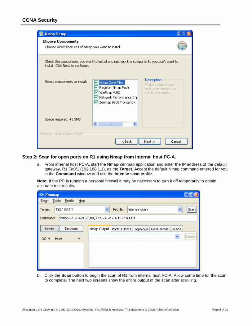
b. On PC-A and PC-C, run the Nmap setup utility and install all components listed, including the Zenmap GUI front-end. Click Next to accept the defaults when prompted.
CCNA Security
All contents are Copyright © 1992–2012 Cisco Systems, Inc. All rights reserved. This document is Cisco Public Information. Page 6 of 32
Step 2: Scan for open ports on R1 using Nmap from internal host PC-A.
a. From internal host PC-A, start the Nmap-Zenmap application and enter the IP address of the default gateway, R1 Fa0/1 (192.168.1.1), as the Target. Accept the default Nmap command entered for you in the Command window and use the Intense scan profile.
Note: If the PC is running a personal firewall it may be necessary to turn it off temporarily to obtain accurate test results.
b. Click the Scan button to begin the scan of R1 from internal host PC-A. Allow some time for the scan to complete. The next two screens show the entire output of the scan after scrolling.

CCNA Security
All contents are Copyright © 1992–2012 Cisco Systems, Inc. All rights reserved. This document is Cisco Public Information. Page 7 of 32
CCNA Security
All contents are Copyright © 1992–2012 Cisco Systems, Inc. All rights reserved. This document is Cisco Public Information. Page 8 of 32
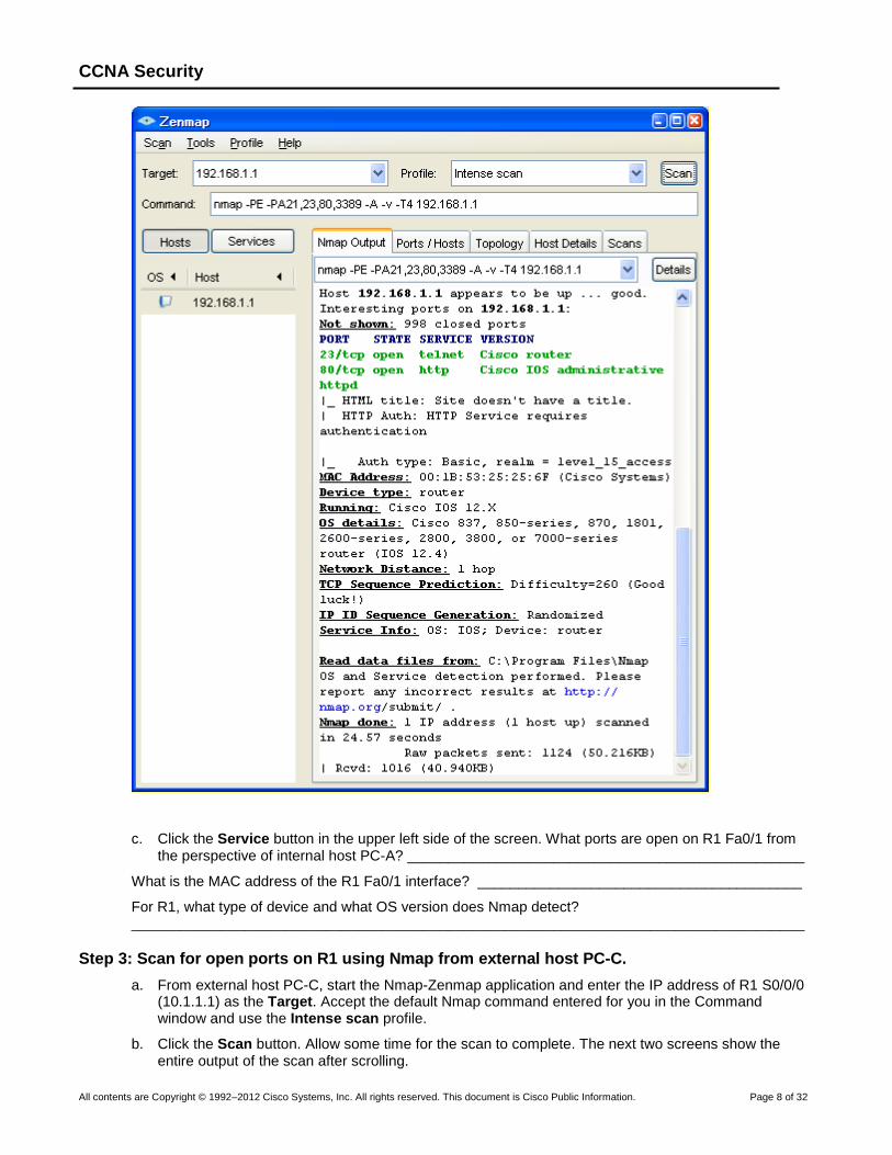
c. Click the Service button in the upper left side of the screen. What ports are open on R1 Fa0/1 from the perspective of internal host PC-A? _________________________________________________
What is the MAC address of the R1 Fa0/1 interface? ________________________________________
For R1, what type of device and what OS version does Nmap detect? ___________________________________________________________________________________
Step 3: Scan for open ports on R1 using Nmap from external host PC-C.
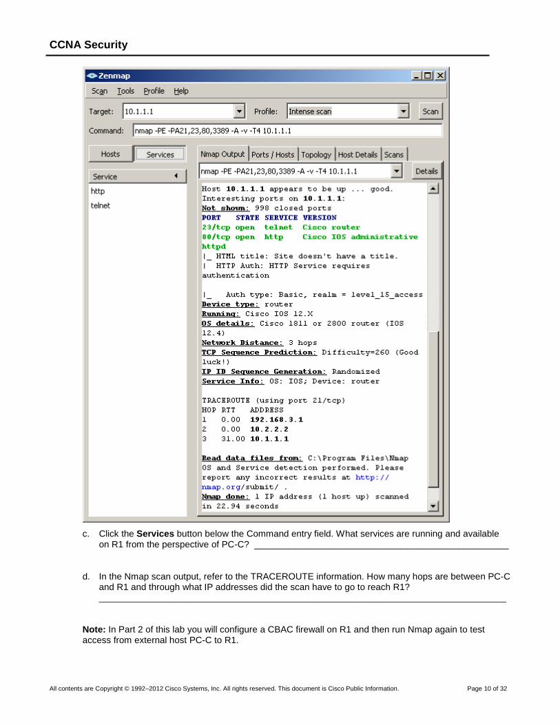
a. From external host PC-C, start the Nmap-Zenmap application and enter the IP address of R1 S0/0/0 (10.1.1.1) as the Target. Accept the default Nmap command entered for you in the Command window and use the Intense scan profile.
b. Click the Scan button. Allow some time for the scan to complete. The next two screens show the entire output of the scan after scrolling.

CCNA Security
All contents are Copyright © 1992–2012 Cisco Systems, Inc. All rights reserved. This document is Cisco Public Information. Page 9 of 32
CCNA Security
All contents are Copyright © 1992–2012 Cisco Systems, Inc. All rights reserved. This document is Cisco Public Information. Page 10 of 32
c. Click the Services button below the Command entry field. What services are running and available on R1 from the perspective of PC-C? __________________________________________________
d. In the Nmap scan output, refer to the TRACEROUTE information. How many hops are between PC-C and R1 and through what IP addresses did the scan have to go to reach R1? ________________________________________________________________________________
Note: In Part 2 of this lab you will configure a CBAC firewall on R1 and then run Nmap again to test access from external host PC-C to R1.
CCNA Security
All contents are Copyright © 1992–2012 Cisco Systems, Inc. All rights reserved. This document is Cisco Public Information. Page 11 of 32
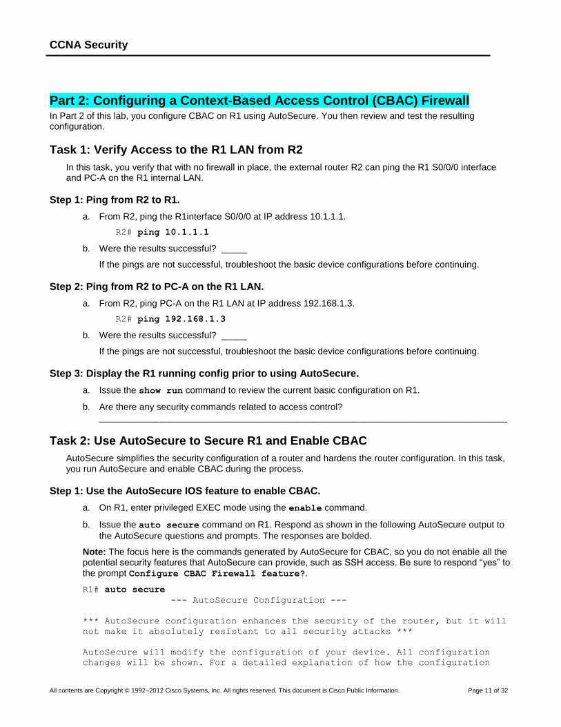
Part 2: Configuring a Context-Based Access Control (CBAC) Firewall In Part 2 of this lab, you configure CBAC on R1 using AutoSecure. You then review and test the resulting configuration.
Task 1: Verify Access to the R1 LAN from R2
In this task, you verify that with no firewall in place, the external router R2 can ping the R1 S0/0/0 interface and PC-A on the R1 internal LAN.
Step 1: Ping from R2 to R1.
a. From R2, ping the R1interface S0/0/0 at IP address 10.1.1.1.
R2# ping 10.1.1.1
b. Were the results successful? _____
If the pings are not successful, troubleshoot the basic device configurations before continuing.
Step 2: Ping from R2 to PC-A on the R1 LAN.
a. From R2, ping PC-A on the R1 LAN at IP address 192.168.1.3.
R2# ping 192.168.1.3
b. Were the results successful? _____
If the pings are not successful, troubleshoot the basic device configurations before continuing.
Step 3: Display the R1 running config prior to using AutoSecure.
a. Issue the show run command to review the current basic configuration on R1.
b. Are there any security commands related to access control? ________________________________________________________________________________
Task 2: Use AutoSecure to Secure R1 and Enable CBAC
AutoSecure simplifies the security configuration of a router and hardens the router configuration. In this task, you run AutoSecure and enable CBAC during the process.
Step 1: Use the AutoSecure IOS feature to enable CBAC.
a. On R1, enter privileged EXEC mode using the enable command.
b. Issue the auto secure command on R1. Respond as shown in the following AutoSecure output to
the AutoSecure questions and prompts. The responses are bolded.
Note: The focus here is the commands generated by AutoSecure for CBAC, so you do not enable all the potential security features that AutoSecure can provide, such as SSH access. Be sure to respond “yes” to the prompt Configure CBAC Firewall feature?.
R1# auto secure
--- AutoSecure Configuration ---
*** AutoSecure configuration enhances the security of the router, but it will
not make it absolutely resistant to all security attacks ***
AutoSecure will modify the configuration of your device. All configuration
changes will be shown. For a detailed explanation of how the configuration
CCNA Security
All contents are Copyright © 1992–2012 Cisco Systems, Inc. All rights reserved. This document is Cisco Public Information. Page 12 of 32
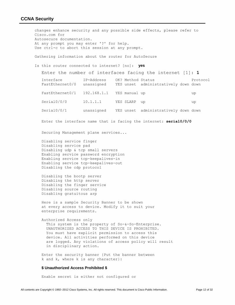
changes enhance security and any possible side effects, please refer to
Cisco.com for
Autosecure documentation.
At any prompt you may enter '?' for help.
Use ctrl-c to abort this session at any prompt.
Gathering information about the router for AutoSecure
Is this router connected to internet? [no]: yes
Enter the number of interfaces facing the internet [1]: 1
Interface IP-Address OK? Method Status Protocol
FastEthernet0/0 unassigned YES unset administratively down down
FastEthernet0/1 192.168.1.1 YES manual up up
Serial0/0/0 10.1.1.1 YES SLARP up up
Serial0/0/1 unassigned YES unset administratively down down
Enter the interface name that is facing the internet: serial0/0/0
Securing Management plane services...
Disabling service finger
Disabling service pad
Disabling udp & tcp small servers
Enabling service password encryption
Enabling service tcp-keepalives-in
Enabling service tcp-keepalives-out
Disabling the cdp protocol
Disabling the bootp server
Disabling the http server
Disabling the finger service
Disabling source routing
Disabling gratuitous arp
Here is a sample Security Banner to be shown
at every access to device. Modify it to suit your
enterprise requirements.
Authorized Access only
This system is the property of So-&-So-Enterprise.
UNAUTHORIZED ACCESS TO THIS DEVICE IS PROHIBITED.
You must have explicit permission to access this
device. All activities performed on this device
are logged. Any violations of access policy will result
in disciplinary action.
Enter the security banner {Put the banner between
k and k, where k is any character}:
$ Unauthorized Access Prohibited $
Enable secret is either not configured or
CCNA Security
All contents are Copyright © 1992–2012 Cisco Systems, Inc. All rights reserved. This document is Cisco Public Information. Page 13 of 32
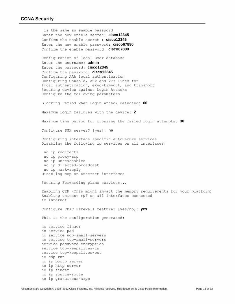
is the same as enable password
Enter the new enable secret: cisco12345
Confirm the enable secret : cisco12345
Enter the new enable password: cisco67890
Confirm the enable password: cisco67890
Configuration of local user database
Enter the username: admin
Enter the password: cisco12345
Confirm the password: cisco12345 Configuring AAA local authentication
Configuring Console, Aux and VTY lines for
local authentication, exec-timeout, and transport
Securing device against Login Attacks
Configure the following parameters
Blocking Period when Login Attack detected: 60
Maximum Login failures with the device: 2
Maximum time period for crossing the failed login attempts: 30
Configure SSH server? [yes]: no
Configuring interface specific AutoSecure services
Disabling the following ip services on all interfaces:
no ip redirects
no ip proxy-arp
no ip unreachables
no ip directed-broadcast
no ip mask-reply
Disabling mop on Ethernet interfaces
Securing Forwarding plane services...
Enabling CEF (This might impact the memory requirements for your platform)
Enabling unicast rpf on all interfaces connected
to internet
Configure CBAC Firewall feature? [yes/no]: yes
This is the configuration generated:
no service finger
no service pad
no service udp-small-servers
no service tcp-small-servers
service password-encryption
service tcp-keepalives-in
service tcp-keepalives-out
no cdp run
no ip bootp server
no ip http server
no ip finger
no ip source-route
no ip gratuitous-arps

CCNA Security
All contents are Copyright © 1992–2012 Cisco Systems, Inc. All rights reserved. This document is Cisco Public Information. Page 14 of 32
no ip identd
banner motd ^C Unauthorized Access Prohibited ^C
security authentication failure rate 10 log
enable secret 5 $1$m.de$Mp5tQr/I8W5VhuQoG6AoA1
enable password 7 05080F1C2243185E415C47
username admin password 7 02050D4808095E731F1A5C
aaa new-model
aaa authentication login local_auth local
line con 0
login authentication local_auth
exec-timeout 5 0
transport output telnet
line aux 0
login authentication local_auth
exec-timeout 10 0
transport output telnet
line vty 0 4
login authentication local_auth
transport input telnet
line tty 1
login authentication local_auth
exec-timeout 15 0
login block-for 60 attempts 2 within 30
service timestamps debug datetime msec localtime show-timezone
service timestamps log datetime msec localtime show-timezone
logging facility local2
logging trap debugging
service sequence-numbers
logging console critical
logging buffered
interface FastEthernet0/0
no ip redirects
no ip proxy-arp
no ip unreachables
no ip directed-broadcast
no ip mask-reply
no mop enabled
interface FastEthernet0/1
no ip redirects
no ip proxy-arp
no ip unreachables
no ip directed-broadcast
no ip mask-reply
no mop enabled
interface Serial0/0/0
no ip redirects
no ip proxy-arp
no ip unreachables
no ip directed-broadcast
no ip mask-reply
interface Serial0/0/1
no ip redirects
no ip proxy-arp
no ip unreachables
no ip directed-broadcast
no ip mask-reply
interface Vlan1
no ip redirects
CCNA Security
All contents are Copyright © 1992–2012 Cisco Systems, Inc. All rights reserved. This document is Cisco Public Information. Page 15 of 32
no ip proxy-arp
no ip unreachables
no ip directed-broadcast
no ip mask-reply
no mop enabled
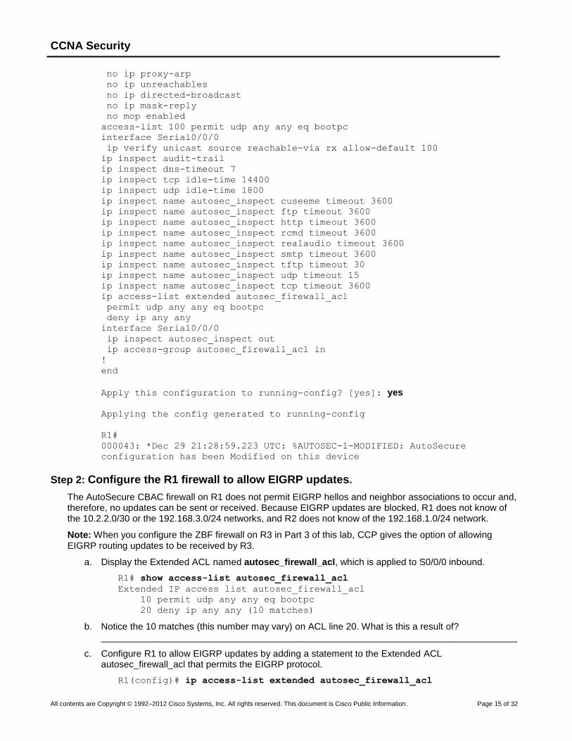
access-list 100 permit udp any any eq bootpc
interface Serial0/0/0
ip verify unicast source reachable-via rx allow-default 100
ip inspect audit-trail
ip inspect dns-timeout 7
ip inspect tcp idle-time 14400
ip inspect udp idle-time 1800
ip inspect name autosec_inspect cuseeme timeout 3600
ip inspect name autosec_inspect ftp timeout 3600
ip inspect name autosec_inspect http timeout 3600
ip inspect name autosec_inspect rcmd timeout 3600
ip inspect name autosec_inspect realaudio timeout 3600
ip inspect name autosec_inspect smtp timeout 3600
ip inspect name autosec_inspect tftp timeout 30
ip inspect name autosec_inspect udp timeout 15
ip inspect name autosec_inspect tcp timeout 3600
ip access-list extended autosec_firewall_acl
permit udp any any eq bootpc
deny ip any any
interface Serial0/0/0
ip inspect autosec_inspect out
ip access-group autosec_firewall_acl in
!
end
Apply this configuration to running-config? [yes]: yes
Applying the config generated to running-config
R1#
000043: *Dec 29 21:28:59.223 UTC: %AUTOSEC-1-MODIFIED: AutoSecure
configuration has been Modified on this device
Step 2: Configure the R1 firewall to allow EIGRP updates.
The AutoSecure CBAC firewall on R1 does not permit EIGRP hellos and neighbor associations to occur and, therefore, no updates can be sent or received. Because EIGRP updates are blocked, R1 does not know of the 10.2.2.0/30 or the 192.168.3.0/24 networks, and R2 does not know of the 192.168.1.0/24 network.
Note: When you configure the ZBF firewall on R3 in Part 3 of this lab, CCP gives the option of allowing EIGRP routing updates to be received by R3.
a. Display the Extended ACL named autosec_firewall_acl, which is applied to S0/0/0 inbound.
R1# show access-list autosec_firewall_acl
Extended IP access list autosec_firewall_acl
10 permit udp any any eq bootpc
20 deny ip any any (10 matches)
b. Notice the 10 matches (this number may vary) on ACL line 20. What is this a result of? ________________________________________________________________________________
c. Configure R1 to allow EIGRP updates by adding a statement to the Extended ACL autosec_firewall_acl that permits the EIGRP protocol.
R1(config)# ip access-list extended autosec_firewall_acl

CCNA Security
All contents are Copyright © 1992–2012 Cisco Systems, Inc. All rights reserved. This document is Cisco Public Information. Page 16 of 32
R1(config-ext-nacl)# 15 permit eigrp any any
R1(config-ext-nacl)# end
d. Display the Extended ACL autosec_firewall_acl again.
R1# show access-list autosec_firewall_acl
Extended IP access list autosec_firewall_acl
10 permit udp any any eq bootpc
15 permit eigrp any any (5)
20 deny ip any any (10)
Notice that there is now some EIGRP packet activity for ACL statement 15.
Note: The ip access-list command can be used to create and edit both named and numbered ACLs
(both standard and extended). The use of this command allows for the insertion of entries in the ACL by specifying unused line numbers (as shown in Step 3c). Also, existing lines in the ACL can be removed by specifying the name or number of the ACL and the then the line number of the entry to be deleted using the no version of the ACL command.
The ip access-list command provides greater flexibility than the earlier access-list command
and is the preferred method of creating ACLs, in most cases. With the access-list command, a new
ACL entry is, by default, appended to the end of the ACL and the ACL is not editable. Additionally, the access-list command cannot be used with named ACLs.
Step 3: Save the running configuration.
Enter privileged EXEC mode using the enable command and provide the enable password cisco12345.
R1# copy run start
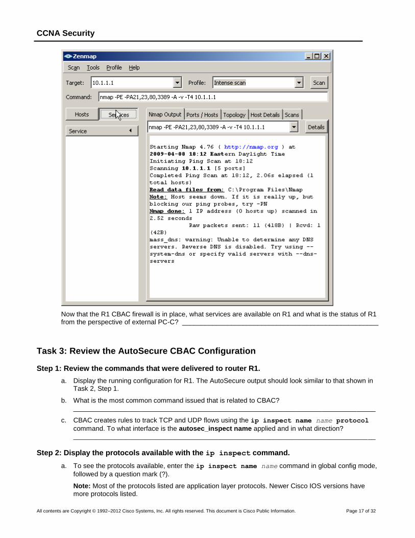
Step 4: Scan for open ports on R1 using Nmap from external host PC-C.
a. From external host PC-C, use Nmap-Zenmap to scan R1 at Target IP address 10.1.1.1. Accept the default Nmap command entered for you in the Command window. Use the Intense scan profile.
b. Click the Scan button to being scanning R1.
CCNA Security
All contents are Copyright © 1992–2012 Cisco Systems, Inc. All rights reserved. This document is Cisco Public Information. Page 17 of 32
Now that the R1 CBAC firewall is in place, what services are available on R1 and what is the status of R1 from the perspective of external PC-C? ____________________________________________________
Task 3: Review the AutoSecure CBAC Configuration
Step 1: Review the commands that were delivered to router R1.
a. Display the running configuration for R1. The AutoSecure output should look similar to that shown in Task 2, Step 1.
b. What is the most common command issued that is related to CBAC? ________________________________________________________________________________
c. CBAC creates rules to track TCP and UDP flows using the ip inspect name name protocol
command. To what interface is the autosec_inspect name applied and in what direction? ________________________________________________________________________________
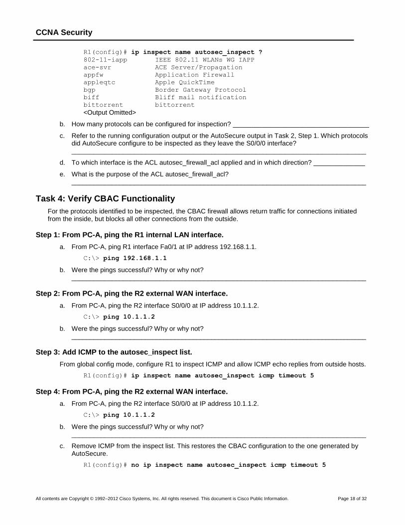
Step 2: Display the protocols available with the ip inspect command.
a. To see the protocols available, enter the ip inspect name name command in global config mode,
followed by a question mark (?).
Note: Most of the protocols listed are application layer protocols. Newer Cisco IOS versions have more protocols listed.
CCNA Security
All contents are Copyright © 1992–2012 Cisco Systems, Inc. All rights reserved. This document is Cisco Public Information. Page 18 of 32
R1(config)# ip inspect name autosec_inspect ?
802-11-iapp IEEE 802.11 WLANs WG IAPP
ace-svr ACE Server/Propagation
appfw Application Firewall
appleqtc Apple QuickTime
bgp Border Gateway Protocol
biff Bliff mail notification
bittorrent bittorrent
<Output Omitted>
b. How many protocols can be configured for inspection? _____________________________________
c. Refer to the running configuration output or the AutoSecure output in Task 2, Step 1. Which protocols did AutoSecure configure to be inspected as they leave the S0/0/0 interface? ________________________________________________________________________________
d. To which interface is the ACL autosec_firewall_acl applied and in which direction? ______________
e. What is the purpose of the ACL autosec_firewall_acl? ________________________________________________________________________________
Task 4: Verify CBAC Functionality
For the protocols identified to be inspected, the CBAC firewall allows return traffic for connections initiated from the inside, but blocks all other connections from the outside.
Step 1: From PC-A, ping the R1 internal LAN interface.
a. From PC-A, ping R1 interface Fa0/1 at IP address 192.168.1.1.
C:\> ping 192.168.1.1
b. Were the pings successful? Why or why not? ________________________________________________________________________________
Step 2: From PC-A, ping the R2 external WAN interface.
a. From PC-A, ping the R2 interface S0/0/0 at IP address 10.1.1.2.
C:\> ping 10.1.1.2
b. Were the pings successful? Why or why not? ________________________________________________________________________________
Step 3: Add ICMP to the autosec_inspect list.
From global config mode, configure R1 to inspect ICMP and allow ICMP echo replies from outside hosts.
R1(config)# ip inspect name autosec_inspect icmp timeout 5
Step 4: From PC-A, ping the R2 external WAN interface.
a. From PC-A, ping the R2 interface S0/0/0 at IP address 10.1.1.2.
C:\> ping 10.1.1.2
b. Were the pings successful? Why or why not? ________________________________________________________________________________
c. Remove ICMP from the inspect list. This restores the CBAC configuration to the one generated by AutoSecure.
R1(config)# no ip inspect name autosec_inspect icmp timeout 5

CCNA Security
All contents are Copyright © 1992–2012 Cisco Systems, Inc. All rights reserved. This document is Cisco Public Information. Page 19 of 32
Step 5: Test Telnet access from R2 to R1.
a. From external router R2, telnet to R1 at IP address 10.1.1.1.
R2> telnet 10.1.1.1
Trying 10.1.1.1 ...
% Connection timed out; remote host not responding
b. Was the telnetting successful? Why or why not? ______________________________________________________________________________
Step 6: Configure R1 to allow Telnet access from external hosts.
a. Display the Extended ACL named autosec_firewall_acl that is applied to S0/0/0 inbound.
R1# show access-list autosec_firewall_acl
Extended IP access list autosec_firewall_acl
10 permit udp any any eq bootpc
15 permit eigrp any any (15)
20 deny ip any any (57 matches)
b. Notice the 57 matches on ACL line 20. What is this a result of? ________________________________________________________________________________
c. Configure R1 to allow Telnet access by adding a statement to the Extended ACL autosec_firewall_acl that permits TCP port 23 (Telnet).
R1(config)# ip access-list extended autosec_firewall_acl
R1(config-ext-nacl)# 18 permit tcp any any eq 23
R1(config-ext-nacl)# end
d. From external router R2, telnet again to R1 at IP address 10.1.1.1.
R2> telnet 10.1.1.1
Trying 10.1.1.1 ... Open
Unauthorized Access Prohibited
User Access Verification
Username: admin
Password: cisco12345
R1>
e. From the Telnet session on R1, display the modified Extended ACL autosec_firewall_acl.
R1> show access-list autosec_firewall_acl
Extended IP access list autosec_firewall_acl
10 permit udp any any eq bootpc
15 permit eigrp any any (25)
18 permit tcp any any eq telnet (12 matches)
20 deny ip any any (57 matches)
f. Notice the new line 18 in the ACL and the 12 matches. What is this a result of? ____________________________________________________________________________
g. Remove Telnet external access from the R1 firewall ACL.
R1(config)# ip access-list extended autosec_firewall_acl
R1(config-ext-nacl)# no 18 permit tcp any any eq telnet
R1(config-ext-nacl)# end
Note: SSH is recommended instead of Telnet, because it provides a more secure way to allow remote administration access to a router or other networking devices. SSH provides encrypted communication;
CCNA Security
All contents are Copyright © 1992–2012 Cisco Systems, Inc. All rights reserved. This document is Cisco Public Information. Page 20 of 32
however, some additional configuration is required to support the SSH connection. Refer to Chapter 2 Lab A for the procedure to enable SSH. For added security, configure SSH as the only input transport on the vty lines and remove Telnet as an input transport. Allowing SSH access to R1 from external hosts also requires adding a statement to the Extended ACL autosec_firewall_acl that permits TCP port 22 (SSH).
Step 7: Test Telnet access from internal PC-A to external router R2.
a. From PC-A, telnet to R2 at IP address 10.1.1.2.
C:\> telnet 10.1.1.2
b. Was the Telnet attempt successful? Why or why not? _______________________________________________________________________________
c. Log in to R2 by providing the vty password of ciscovtypass.
d. Leave the Telnet session open.
Task 5: Verify CBAC Configuration and Operation
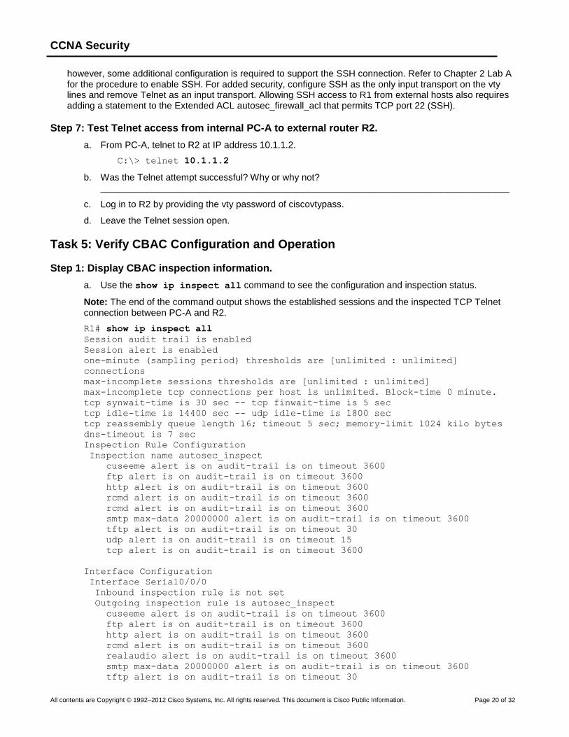
Step 1: Display CBAC inspection information.
a. Use the show ip inspect all command to see the configuration and inspection status.
Note: The end of the command output shows the established sessions and the inspected TCP Telnet connection between PC-A and R2.
R1# show ip inspect all
Session audit trail is enabled
Session alert is enabled
one-minute (sampling period) thresholds are [unlimited : unlimited]
connections
max-incomplete sessions thresholds are [unlimited : unlimited]
max-incomplete tcp connections per host is unlimited. Block-time 0 minute.
tcp synwait-time is 30 sec -- tcp finwait-time is 5 sec
tcp idle-time is 14400 sec -- udp idle-time is 1800 sec
tcp reassembly queue length 16; timeout 5 sec; memory-limit 1024 kilo bytes
dns-timeout is 7 sec
Inspection Rule Configuration
Inspection name autosec_inspect
cuseeme alert is on audit-trail is on timeout 3600
ftp alert is on audit-trail is on timeout 3600
http alert is on audit-trail is on timeout 3600
rcmd alert is on audit-trail is on timeout 3600
rcmd alert is on audit-trail is on timeout 3600
smtp max-data 20000000 alert is on audit-trail is on timeout 3600
tftp alert is on audit-trail is on timeout 30
udp alert is on audit-trail is on timeout 15
tcp alert is on audit-trail is on timeout 3600
Interface Configuration
Interface Serial0/0/0
Inbound inspection rule is not set
Outgoing inspection rule is autosec_inspect
cuseeme alert is on audit-trail is on timeout 3600
ftp alert is on audit-trail is on timeout 3600
http alert is on audit-trail is on timeout 3600
rcmd alert is on audit-trail is on timeout 3600
realaudio alert is on audit-trail is on timeout 3600
smtp max-data 20000000 alert is on audit-trail is on timeout 3600
tftp alert is on audit-trail is on timeout 30
CCNA Security
All contents are Copyright © 1992–2012 Cisco Systems, Inc. All rights reserved. This document is Cisco Public Information. Page 21 of 32
udp alert is on audit-trail is on timeout 15
tcp alert is on audit-trail is on timeout 3600
Inbound access list is autosec_firewall_acl
Outgoing access list is not set
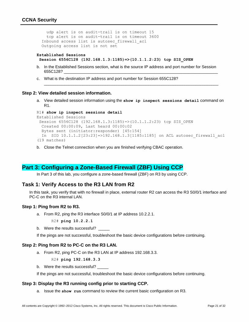
Established Sessions
Session 6556C128 (192.168.1.3:1185)=>(10.1.1.2:23) tcp SIS_OPEN
b. In the Established Sessions section, what is the source IP address and port number for Session 655C128? ____________________________________________________________________
c. What is the destination IP address and port number for Session 655C128? _____________________________________________________________________________
Step 2: View detailed session information.
a. View detailed session information using the show ip inspect sessions detail command on
R1.
R1# show ip inspect sessions detail
Established Sessions
Session 6556C128 (192.168.1.3:1185)=>(10.1.1.2:23) tcp SIS_OPEN
Created 00:00:09, Last heard 00:00:02
Bytes sent (initiator:responder) [45:154]
In SID 10.1.1.2[23:23]=>192.168.1.3[1185:1185] on ACL autosec_firewall_acl
(19 matches)
b. Close the Telnet connection when you are finished verifying CBAC operation.
Part 3: Configuring a Zone-Based Firewall (ZBF) Using CCP In Part 3 of this lab, you configure a zone-based firewall (ZBF) on R3 by using CCP.
Task 1: Verify Access to the R3 LAN from R2
In this task, you verify that with no firewall in place, external router R2 can access the R3 S0/0/1 interface and PC-C on the R3 internal LAN.
Step 1: Ping from R2 to R3.
a. From R2, ping the R3 interface S0/0/1 at IP address 10.2.2.1.
R2# ping 10.2.2.1
b. Were the results successful? _____
If the pings are not successful, troubleshoot the basic device configurations before continuing.
Step 2: Ping from R2 to PC-C on the R3 LAN.
a. From R2, ping PC-C on the R3 LAN at IP address 192.168.3.3.
R2# ping 192.168.3.3
b. Were the results successful? _____
If the pings are not successful, troubleshoot the basic device configurations before continuing.
Step 3: Display the R3 running config prior to starting CCP.
a. Issue the show run command to review the current basic configuration on R3.
CCNA Security
All contents are Copyright © 1992–2012 Cisco Systems, Inc. All rights reserved. This document is Cisco Public Information. Page 22 of 32
b. Verify the R3 basic configuration as performed in Part 1 of the lab. Are there any security commands related to access control? ___________________________________________________________
Task 2: Create a Zone-Based Policy Firewall
In this task, you use CCP to create a zone-based policy firewall on R3.
Step 1: Configure the enable secret password and HTTP router access prior to starting CCP.
a. From the CLI, configure the enable secret password for use with CCP on R3.
R3(config)# enable secret cisco12345
b. Enable the HTTP server on R3.
R3(config)# ip http server
c. Add admin user to the local database.
R3(config)# username admin privilege 15 secret cisco12345
d. Have CCP use the local database to authenticate web sessions.
R3(config)# ip http authentication local
Step 2: Access CCP and discover R3.
a. Start CCP on PC-C. In the Manage Devices window, add R3 IP address 192.168.3.1 in the first IP address field. Enter admin in the Username field, and cisco12345 in the Password field.
b. At the CCP Dashboard, click the Discover button to discover and connect to R3. If discovery fails,
click the Discovery Details button to determine the problem.
Step 3: Use the CCP Firewall wizard to configure a zone-based firewall.
a. Click on Monitor > Security > Firewall Status. What is the state of the Firewall Policies? ________________________________________________________________________________
b. Click Configure > Security > Firewall > Firewall, read through the overview descriptions for the Basic and Advanced Firewall options. What are some of the key differences? ________________________________________________________________________________________________________________________________________________________________________________________________________________________________________________
CCNA Security
All contents are Copyright © 1992–2012 Cisco Systems, Inc. All rights reserved. This document is Cisco Public Information. Page 23 of 32
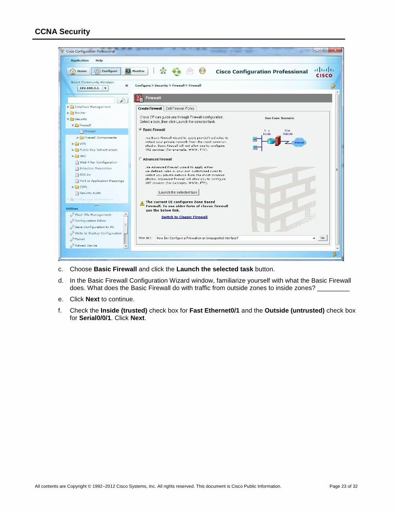
c. Choose Basic Firewall and click the Launch the selected task button.
d. In the Basic Firewall Configuration Wizard window, familiarize yourself with what the Basic Firewall does. What does the Basic Firewall do with traffic from outside zones to inside zones? _________
e. Click Next to continue.
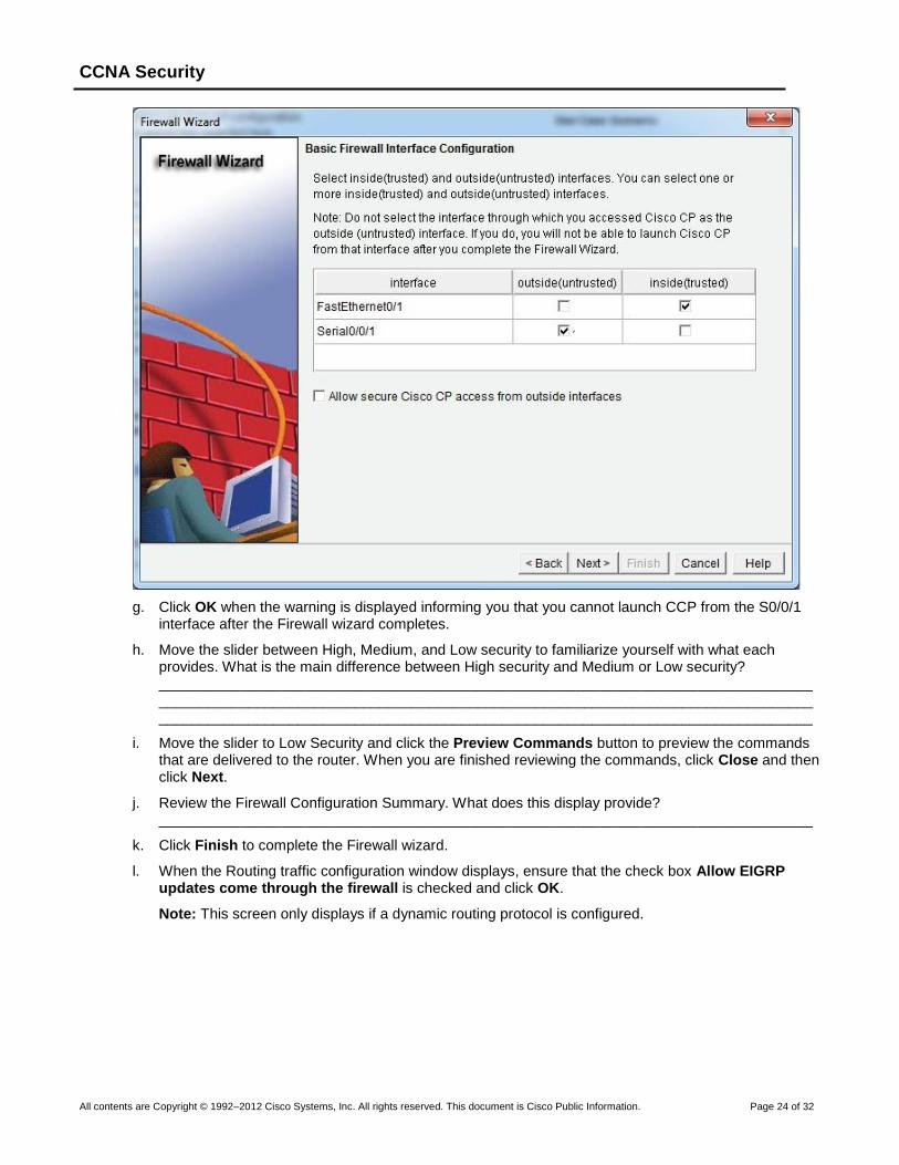
f. Check the Inside (trusted) check box for Fast Ethernet0/1 and the Outside (untrusted) check box for Serial0/0/1. Click Next.
CCNA Security
All contents are Copyright © 1992–2012 Cisco Systems, Inc. All rights reserved. This document is Cisco Public Information. Page 24 of 32
g. Click OK when the warning is displayed informing you that you cannot launch CCP from the S0/0/1 interface after the Firewall wizard completes.
h. Move the slider between High, Medium, and Low security to familiarize yourself with what each provides. What is the main difference between High security and Medium or Low security? ________________________________________________________________________________________________________________________________________________________________________________________________________________________________________________
i. Move the slider to Low Security and click the Preview Commands button to preview the commands that are delivered to the router. When you are finished reviewing the commands, click Close and then click Next.
j. Review the Firewall Configuration Summary. What does this display provide? ________________________________________________________________________________
k. Click Finish to complete the Firewall wizard.
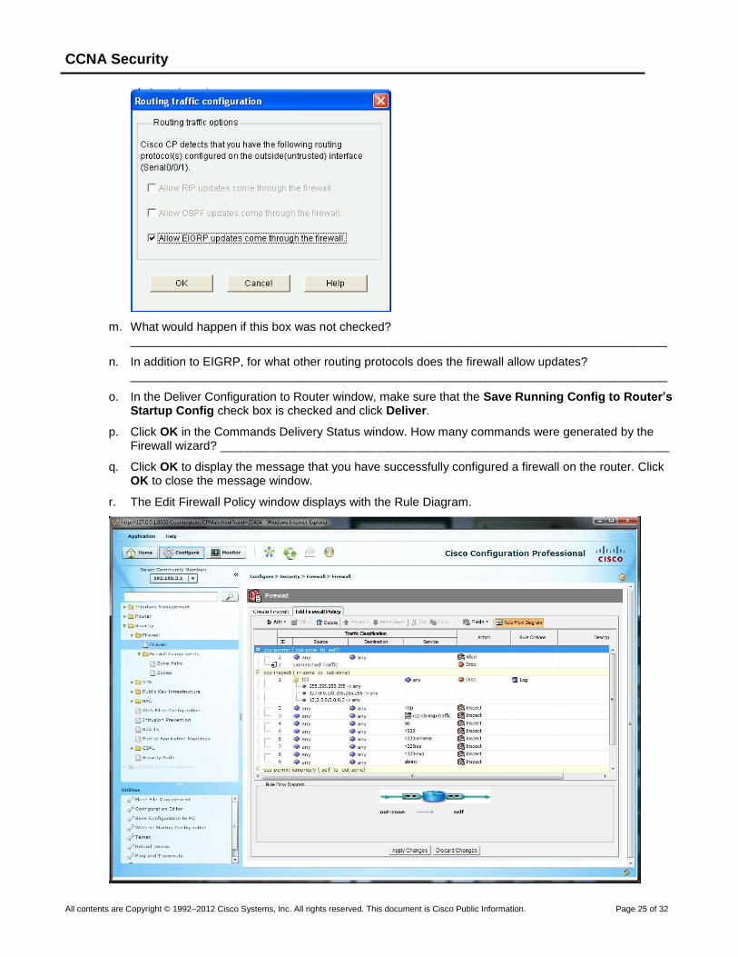
l. When the Routing traffic configuration window displays, ensure that the check box Allow EIGRP updates come through the firewall is checked and click OK.
Note: This screen only displays if a dynamic routing protocol is configured.
CCNA Security
All contents are Copyright © 1992–2012 Cisco Systems, Inc. All rights reserved. This document is Cisco Public Information. Page 25 of 32
m. What would happen if this box was not checked? ________________________________________________________________________________
n. In addition to EIGRP, for what other routing protocols does the firewall allow updates? ________________________________________________________________________________
o. In the Deliver Configuration to Router window, make sure that the Save Running Config to Router’s Startup Config check box is checked and click Deliver.
p. Click OK in the Commands Delivery Status window. How many commands were generated by the Firewall wizard? ___________________________________________________________________
q. Click OK to display the message that you have successfully configured a firewall on the router. Click OK to close the message window.
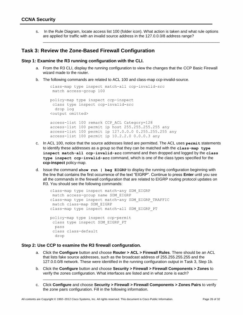
r. The Edit Firewall Policy window displays with the Rule Diagram.
CCNA Security
All contents are Copyright © 1992–2012 Cisco Systems, Inc. All rights reserved. This document is Cisco Public Information. Page 26 of 32
s. In the Rule Diagram, locate access list 100 (folder icon). What action is taken and what rule options are applied for traffic with an invalid source address in the 127.0.0.0/8 address range? ________________________________________________________________________________
Task 3: Review the Zone-Based Firewall Configuration
Step 1: Examine the R3 running configuration with the CLI.
a. From the R3 CLI, display the running configuration to view the changes that the CCP Basic Firewall wizard made to the router.
b. The following commands are related to ACL 100 and class-map ccp-invalid-source.
class-map type inspect match-all ccp-invalid-src
match access-group 100
policy-map type inspect ccp-inspect
class type inspect ccp-invalid-src
drop log
<output omitted>
access-list 100 remark CCP_ACL Category=128
access-list 100 permit ip host 255.255.255.255 any
access-list 100 permit ip 127.0.0.0 0.255.255.255 any
access-list 100 permit ip 10.2.2.0 0.0.0.3 any
c. In ACL 100, notice that the source addresses listed are permitted. The ACL uses permit statements
to identify these addresses as a group so that they can be matched with the class-map type
inspect match-all ccp-invalid-src command and then dropped and logged by the class
type inspect ccp-invalid-src command, which is one of the class types specified for the
ccp-inspect policy-map.
d. Issue the command show run | beg EIGRP to display the running configuration beginning with
the line that contains the first occurrence of the text “EIGRP”. Continue to press Enter until you see all the commands in the firewall configuration that are related to EIGRP routing protocol updates on R3. You should see the following commands:
class-map type inspect match-any SDM_EIGRP
match access-group name SDM_EIGRP
class-map type inspect match-any SDM_EIGRP_TRAFFIC
match class-map SDM_EIGRP
class-map type inspect match-all SDM_EIGRP_PT
policy-map type inspect ccp-permit
class type inspect SDM_EIGRP_PT
pass
class class-default
drop
Step 2: Use CCP to examine the R3 firewall configuration.
a. Click the Configure button and choose Router > ACL > Firewall Rules. There should be an ACL that lists fake source addresses, such as the broadcast address of 255.255.255.255 and the 127.0.0.0/8 network. These were identified in the running configuration output in Task 3, Step 1b.
b. Click the Configure button and choose Security > Firewall > Firewall Components > Zones to verify the zones configuration. What interfaces are listed and in what zone is each? _______________________________________________________________________________
c. Click Configure and choose Security > Firewall > Firewall Components > Zones Pairs to verify the zone pairs configuration. Fill in the following information.

CCNA Security
All contents are Copyright © 1992–2012 Cisco Systems, Inc. All rights reserved. This document is Cisco Public Information. Page 27 of 32
Zone Pair Source Destination Policy
d. What is C3PL short for? _____________________________________________________________
e. Click Configure and choose Security > C3PL > Class Map > Inspection. How many class maps were created by the CCP Firewall wizard? _____
f. Choose Security > C3PL > Policy Map > Protocol Inspection. How many policy maps were created by the CCP Firewall wizard? _____
g. Examine the details for the policy map ccp-permit that is applied to the ccp-zp-out-self zone pair. Fill in the information below. List the action for the traffic matching each of the class maps referenced within the ccp-permit policy map.
Match Class Name: _________________ Action: __________ Match Class Name: _________________ Action: __________
Task 4: Verify EIGRP Routing Functionality on R3
Step 1: Display the R3 routing table using the CLI.
a. In Task 2, Step 3, the Firewall wizard configured the router to allow EIGRP updates. Verify that EIGRP messages are still being exchanged using the show ip route command and verify that
there are still EIGRP learned routes in the routing table.
R3# show ip route
Codes: C - connected, S - static, R - RIP, M - mobile, B - BGP
D - EIGRP, EX - EIGRP external, O - OSPF, IA - OSPF inter area
<Output omitted>
Gateway of last resort is not set
10.0.0.0/30 is subnetted, 2 subnets
C 10.2.2.0 is directly connected, Serial0/0/1
D 10.1.1.0 [90/21024000] via 10.2.2.2, 00:34:12, Serial0/0/1
D 192.168.1.0/24 [90/21026560] via 10.2.2.2, 00:32:16, Serial0/0/1
C 192.168.3.0/24 is directly connected, FastEthernet0/1
b. Which networks has R3 learned via the EIGRP routing protocol? _____________________________
Task 5: Verify Zone-Based Firewall Functionality
Step 1: From PC-C, ping the R3 internal LAN interface.
a. From PC-C, ping the R3 interface Fa0/1 at IP address 192.168.3.1.
C:\> ping 192.168.3.1
b. Were the pings successful? Why or why not? ________________________________________________________________________________
Step 2: From PC-C, ping the R2 external WAN interface.
a. From PC-C, ping the R2 interface S0/0/1 at IP address 10.2.2.2.

CCNA Security
All contents are Copyright © 1992–2012 Cisco Systems, Inc. All rights reserved. This document is Cisco Public Information. Page 28 of 32
C:\> ping 10.2.2.2
b. Were the pings successful? Why or why not? _______________________________________________________________________________
Step 3: From R2 ping PC-C.
a. From external router R2, ping PC-C at IP address 192.168.3.3.
R2# ping 192.168.3.3
b. Were the pings successful? Why or why not? _______________________________________________________________________________
Step 4: Telnet from R2 to R3.
a. From router R2, telnet to R3 at IP address 10.2.2.1.
R2# telnet 10.2.2.1
Trying 10.2.2.1 ... Open
Trying 10.2.2.1 ...
% Connection timed out; remote host not responding
b. Why was telnetting unsuccessful? ___________________________________________________
Step 5: Telnet from internal PC-C to external router R2.
a. From PC-C on the R3 internal LAN, telnet to R2 at IP address 10.2.2.2 and log in.
C:\> telnet 10.2.2.2
User Access verification
Password: ciscovtypass
b. With the Telnet session open from PC-C to R2, enter privileged EXEC mode with the enable
command and password cisco12345.
c. Issue the command show policy-map type inspect zone-pair session on R3. Continue
pressing Enter until you see an Inspect Established session section toward the end. Your output should look similar to the following.
Inspect
Number of Established Sessions = 1
Established Sessions
Session 657344C0 (192.168.3.3:1274)=>(10.2.2.2:23) tacacs:tcp
SIS_OPEN
Created 00:01:20, Last heard 00:01:13
Bytes sent (initiator:responder) [45:65]
d. In the Established Sessions in the output, what is the source IP address and port number for Session 657344C0? _______________________________________________________________________
e. What is the destination IP address and port number for Session 657344C0? ________________________________________________________________________________
Step 6: Use CCP Monitor to verify the ZBF function.
a. From CCP, click the Monitor button at the top of the screen and choose Security > Firewall Status.
b. Choose the ccp-zp-out-self policy from the list of policies. This policy applies to traffic from the outside zone to the router (self) zone.
CCNA Security
All contents are Copyright © 1992–2012 Cisco Systems, Inc. All rights reserved. This document is Cisco Public Information. Page 29 of 32
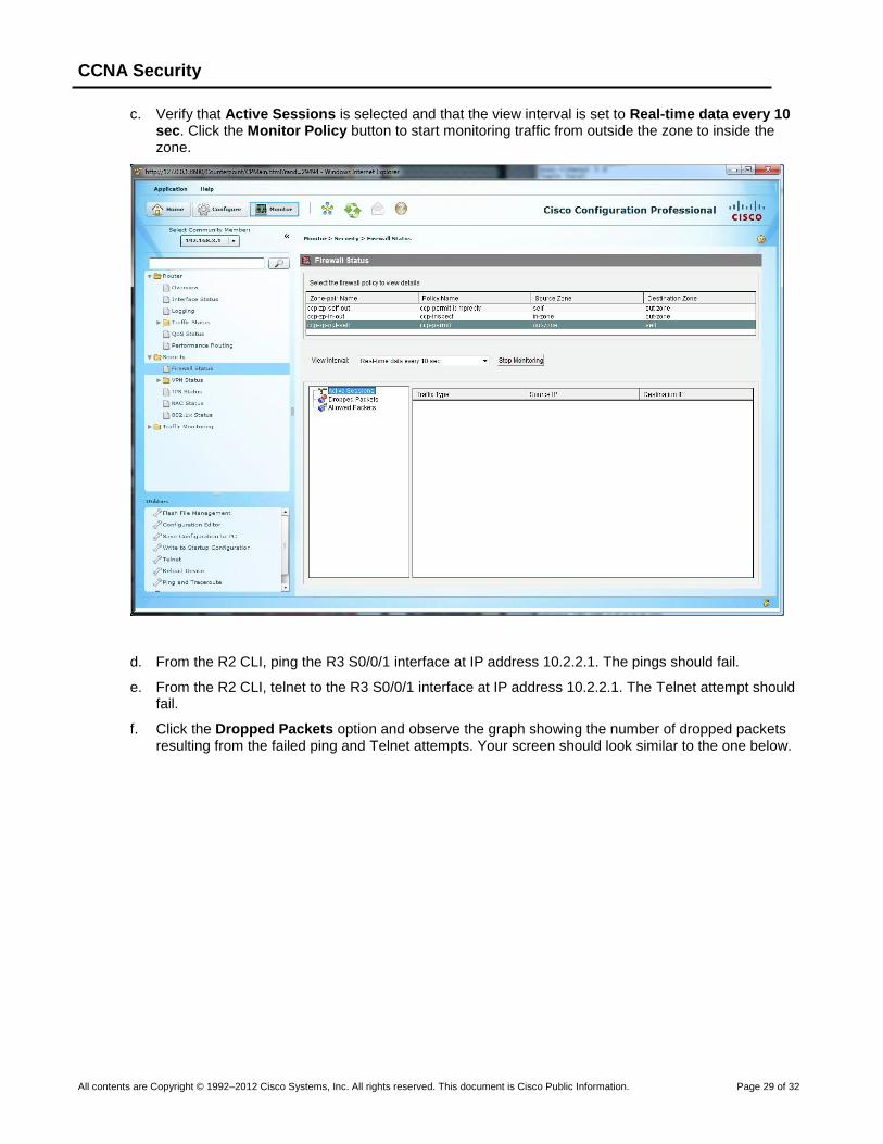
c. Verify that Active Sessions is selected and that the view interval is set to Real-time data every 10 sec. Click the Monitor Policy button to start monitoring traffic from outside the zone to inside the zone.
d. From the R2 CLI, ping the R3 S0/0/1 interface at IP address 10.2.2.1. The pings should fail.
e. From the R2 CLI, telnet to the R3 S0/0/1 interface at IP address 10.2.2.1. The Telnet attempt should fail.
f. Click the Dropped Packets option and observe the graph showing the number of dropped packets resulting from the failed ping and Telnet attempts. Your screen should look similar to the one below.
CCNA Security
All contents are Copyright © 1992–2012 Cisco Systems, Inc. All rights reserved. This document is Cisco Public Information. Page 30 of 32
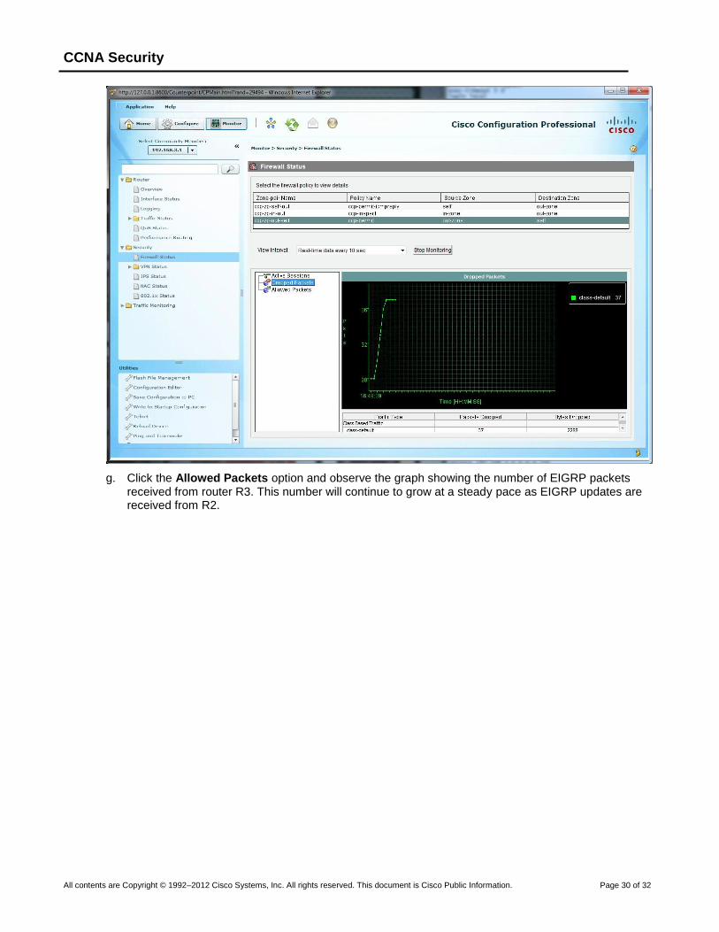
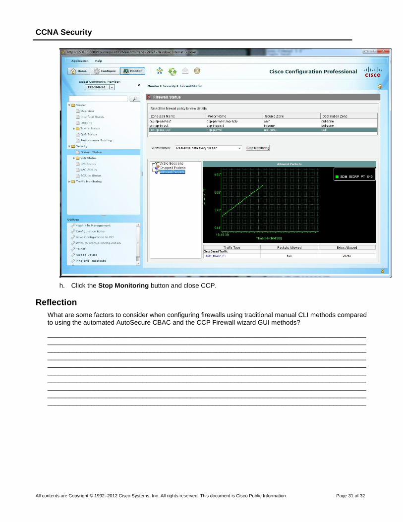
g. Click the Allowed Packets option and observe the graph showing the number of EIGRP packets received from router R3. This number will continue to grow at a steady pace as EIGRP updates are received from R2.
CCNA Security
All contents are Copyright © 1992–2012 Cisco Systems, Inc. All rights reserved. This document is Cisco Public Information. Page 31 of 32
h. Click the Stop Monitoring button and close CCP.
Reflection
What are some factors to consider when configuring firewalls using traditional manual CLI methods compared to using the automated AutoSecure CBAC and the CCP Firewall wizard GUI methods?
______________________________________________________________________________________________________________________________________________________________________________________________________________________________________________________________________________________________________________________________________________________________________________________________________________________________________________________________________________________________________________________________________________________________________________________________________________________________________________________________________________________________________________________________________________________________________________________________________________________________________________________________________________________________________
CCNA Security
All contents are Copyright © 1992–2012 Cisco Systems, Inc. All rights reserved. This document is Cisco Public Information. Page 32 of 32
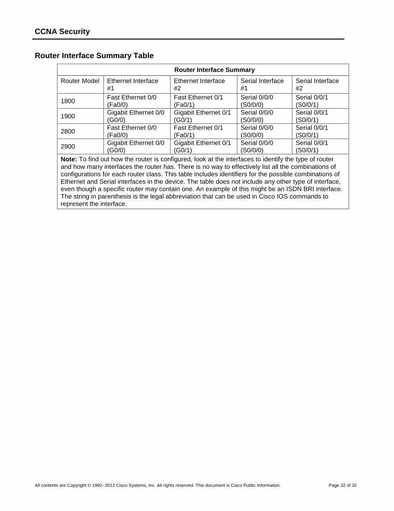
Router Interface Summary Table
Router Interface Summary
Router Model Ethernet Interface #1
Ethernet Interface #2
Serial Interface #1
Serial Interface #2
1800 Fast Ethernet 0/0 (Fa0/0)
Fast Ethernet 0/1 (Fa0/1)
Serial 0/0/0 (S0/0/0)
Serial 0/0/1 (S0/0/1)
1900 Gigabit Ethernet 0/0 (G0/0)
Gigabit Ethernet 0/1 (G0/1)
Serial 0/0/0 (S0/0/0)
Serial 0/0/1 (S0/0/1)
2800 Fast Ethernet 0/0 (Fa0/0)
Fast Ethernet 0/1 (Fa0/1)
Serial 0/0/0 (S0/0/0)
Serial 0/0/1 (S0/0/1)
2900 Gigabit Ethernet 0/0 (G0/0)
Gigabit Ethernet 0/1 (G0/1)
Serial 0/0/0 (S0/0/0)
Serial 0/0/1 (S0/0/1)
Note: To find out how the router is configured, look at the interfaces to identify the type of router and how many interfaces the router has. There is no way to effectively list all the combinations of configurations for each router class. This table includes identifiers for the possible combinations of Ethernet and Serial interfaces in the device. The table does not include any other type of interface, even though a specific router may contain one. An example of this might be an ISDN BRI interface. The string in parenthesis is the legal abbreviation that can be used in Cisco IOS commands to represent the interface.