Embed Size (px)
Citation preview
CHAPTER 28
MAGNETIC INDUCTION
• Magnetic field and magnetic flux
• Induced emf and Faraday’s Law
• Lenz’s Law
• Motional emf
• Eddy currents
• Self inductance
• R-L circuits and energy
Faraday’s Law put to good use: a flashlight with no batteries! Just shake it to produce electrical power!
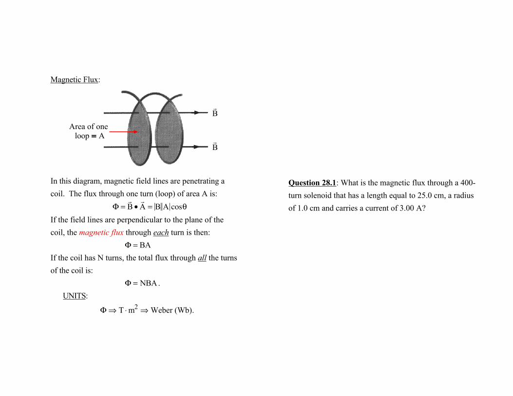
Magnetic Flux:
In this diagram, magnetic field lines are penetrating a coil. The flux through one turn (loop) of area A is:
Φ =! B •! A = B A cosθ
If the field lines are perpendicular to the plane of the coil, the magnetic flux through each turn is then:
Φ = BAIf the coil has N turns, the total flux through all the turns of the coil is:
Φ = NBA.UNITS:
Φ⇒ T ⋅m2 ⇒ Weber (Wb).
! B
! B
Area of one loop = A
Question 28.1: What is the magnetic flux through a 400-turn solenoid that has a length equal to 25.0 cm, a radius of 1.0 cm and carries a current of 3.00 A?
The magnetic flux through one turn is
Φ =! B •! A =
! B ! A cosθ,
but in a solenoid, the flux lines are parallel to the axis of the solenoid, i.e., perpendicular to the plane of each turn.
∴θ = 0,so for N turns,
Φ = NBA. The magnetic field strength in a solenoid is
B = µ"nI,
where n = Nℓ is the number of turns per unit length.
∴Φ = N µ"
Nℓ
I⎛ ⎝
⎞ ⎠ πr2 =
N2µ"Iπr2
ℓ
=(400)2(4π ×10−7 )(3.00 A)π(0.01 m)2
0.25 m
= 7.58 ×10⁻⁴ Wb.
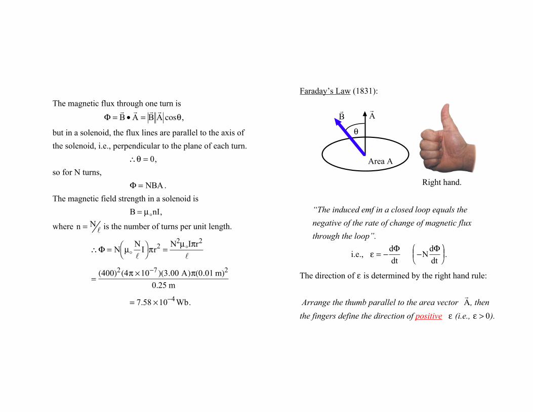
Faraday’s Law (1831):
“The induced emf in a closed loop equals the negative of the rate of change of magnetic flux through the loop”.
i.e., ε = −
dΦdt
−NdΦdt
⎛ ⎝ ⎜
⎞ ⎠ ⎟ .
The direction of ε is determined by the right hand rule:
Arrange the thumb parallel to the area vector ! A , then
the fingers define the direction of positive ε (i.e., ε > 0).
Right hand.
! A
! B
θ
Area A
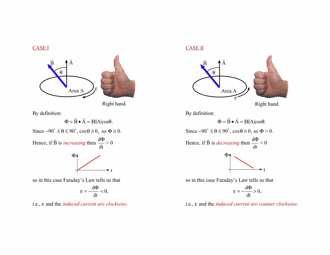
CASE I
By definition:
Φ =! B •! A = B A cosθ.
Since −90" ≤ θ ≤ 90", cosθ ≥ 0, so Φ ≥ 0.
Hence, if ! B is increasing then
dΦdt
> 0
so in this case Faraday’s Law tells us that
ε = −
dΦdt
< 0,
i.e., ε and the induced current are clockwise.
Φ
t
Right hand.
ε
! A
! B
θ
Area A
CASE II
By definition:
Φ =! B •! A = B A cosθ.
Since −90" ≤ θ ≤ 90", cosθ ≥ 0, so Φ > 0.
Hence, if ! B is decreasing then
dΦdt
< 0
so in this case Faraday’s Law tells us that
ε = −
dΦdt
> 0,
i.e., ε and the induced current are counter clockwise.
Φ
t
Right hand.ε
! A
! B
θ
Area A
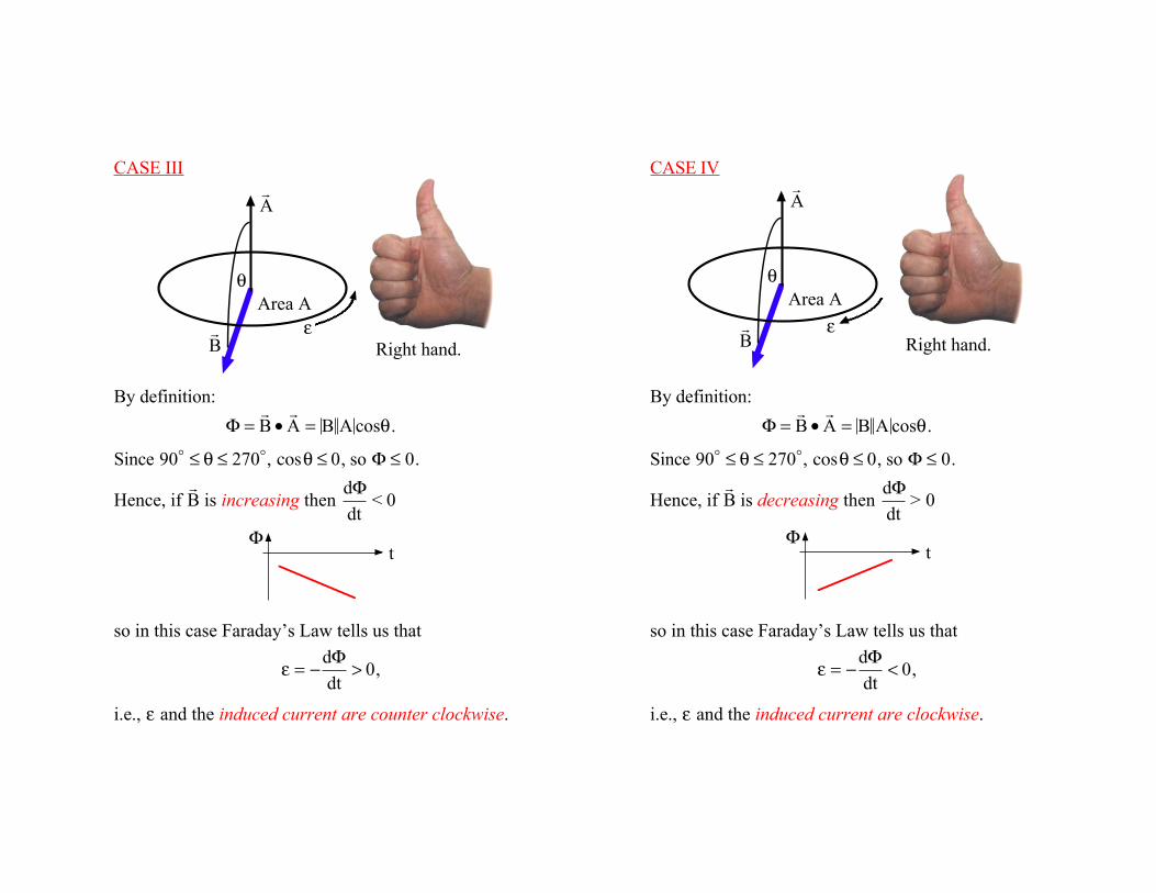
CASE III
By definition:
Φ =! B •! A = B A cosθ.
Since 90" ≤ θ ≤ 270", cosθ ≤ 0, so Φ ≤ 0.
Hence, if ! B is increasing then
dΦdt
< 0
so in this case Faraday’s Law tells us that
ε = −
dΦdt
> 0,
i.e., ε and the induced current are counter clockwise.
Φ t
Right hand.ε
! A
! B
θArea A
CASE IV
By definition:
Φ =! B •! A = B A cosθ.
Since 90" ≤ θ ≤ 270", cosθ ≤ 0, so Φ ≤ 0.
Hence, if ! B is decreasing then
dΦdt
> 0
so in this case Faraday’s Law tells us that
ε = −
dΦdt
< 0,
i.e., ε and the induced current are clockwise.
Φ t
Right hand.ε
! A
! B
θArea A
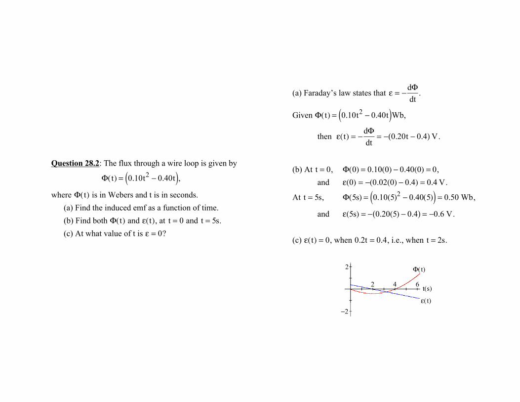
Question 28.2: The flux through a wire loop is given by
Φ(t) = 0.10t2 − 0.40t( ),where Φ(t) is in Webers and t is in seconds.
(a) Find the induced emf as a function of time.(b) Find both Φ(t) and ε(t), at t = 0 and t = 5s.(c) At what value of t is ε = 0?
(a) Faraday’s law states that ε = −
dΦdt
.
Given Φ(t) = 0.10t2 − 0.40t( )Wb,
then ε(t) = −
dΦdt
= − 0.20t − 0.4( ) V.
(b) At t = 0, Φ(0) = 0.10(0) − 0.40(0) = 0,and ε(0) = −(0.02(0) − 0.4) = 0.4 V.
At t = 5s, Φ(5s) = 0.10(5)2 − 0.40(5)( ) = 0.50 Wb,
and ε(5s) = − 0.20(5) − 0.4( ) = −0.6 V.
(c) ε(t) = 0, when 0.2t = 0.4, i.e., when t = 2s.
ε( t)
Φ( t) 2
−2
2 4 6 t(s)
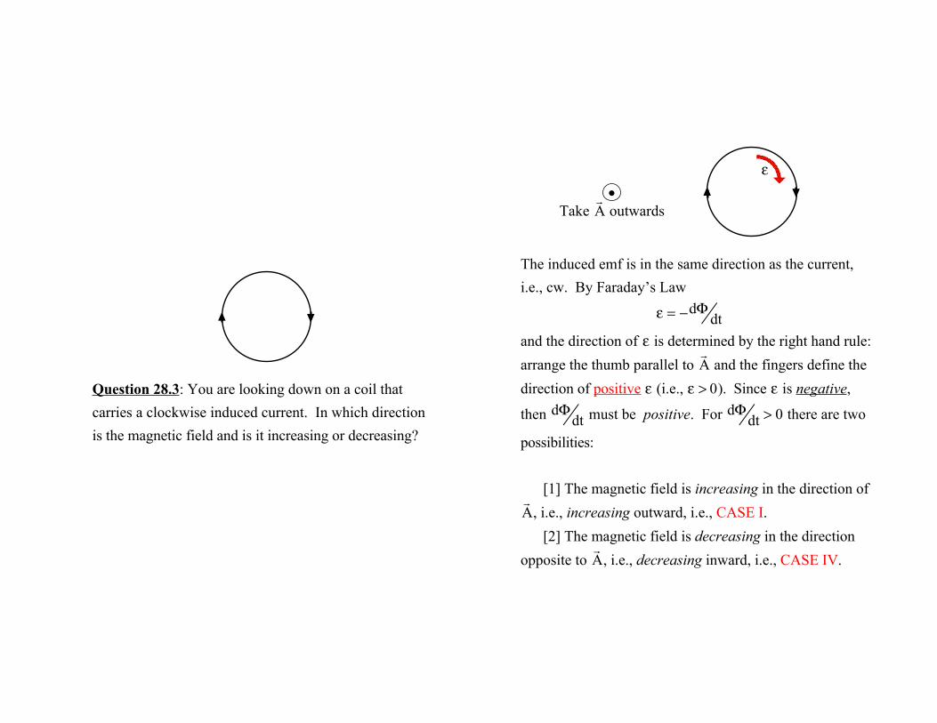
Question 28.3: You are looking down on a coil that carries a clockwise induced current. In which direction is the magnetic field and is it increasing or decreasing?
The induced emf is in the same direction as the current, i.e., cw. By Faraday’s Law
ε = −dΦdt
and the direction of ε is determined by the right hand rule:
arrange the thumb parallel to ! A and the fingers define the
direction of positive ε (i.e., ε > 0). Since ε is negative,
then dΦ
dt must be positive. For dΦ
dt > 0 there are two
possibilities:
[1] The magnetic field is increasing in the direction of
! A , i.e., increasing outward, i.e., CASE I.
[2] The magnetic field is decreasing in the direction
opposite to ! A , i.e., decreasing inward, i.e., CASE IV.
ε•
Take ! A outwards
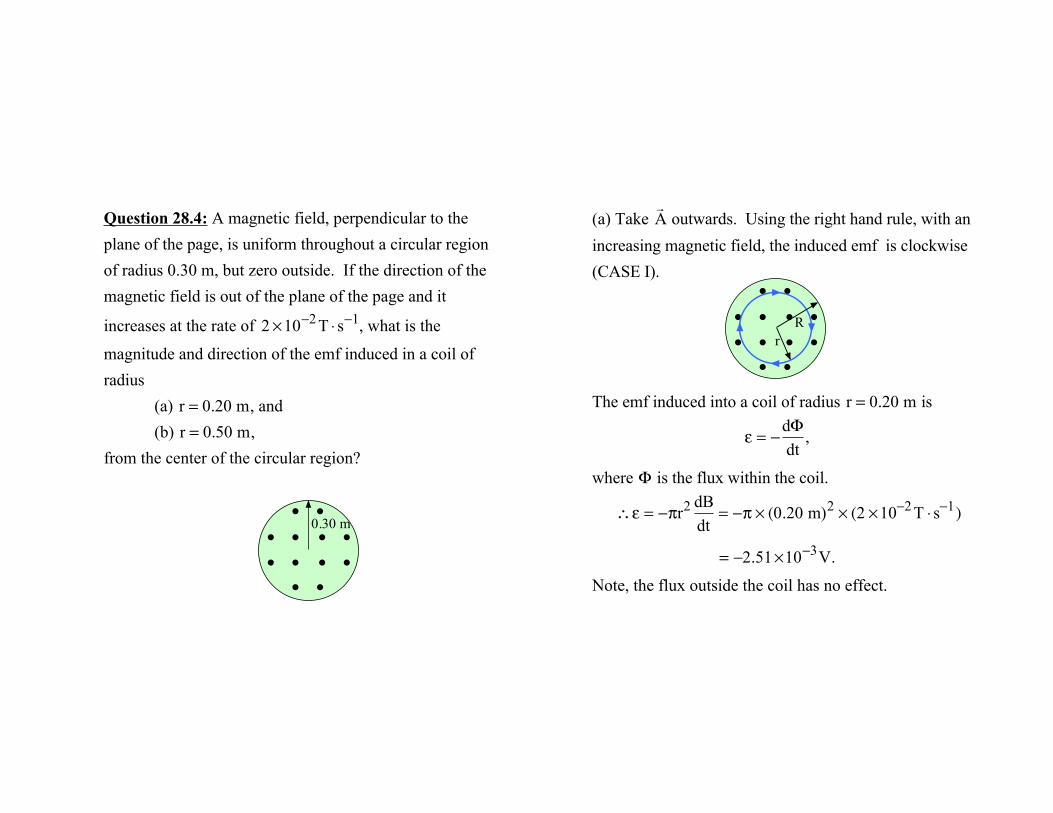
Question 28.4: A magnetic field, perpendicular to the plane of the page, is uniform throughout a circular region of radius 0.30 m, but zero outside. If the direction of the magnetic field is out of the plane of the page and it
increases at the rate of 2 ×10⁻² T ⋅ s−1, what is the
magnitude and direction of the emf induced in a coil of radius
(a) r = 0.20 m, and(b) r = 0.50 m,
from the center of the circular region?
• •
• •
• • • •• • • •
0.30 m
(a) Take ! A outwards. Using the right hand rule, with an
increasing magnetic field, the induced emf is clockwise (CASE I).
The emf induced into a coil of radius r = 0.20 m is
ε = −
dΦdt
,
where Φ is the flux within the coil.
∴ε = −πr2 dB
dt= −π × (0.20 m)2 × (2 ×10−2 T ⋅ s−1)
= −2.51×10⁻³V.
Note, the flux outside the coil has no effect.
• •
• •
• • • •• • • • r
R
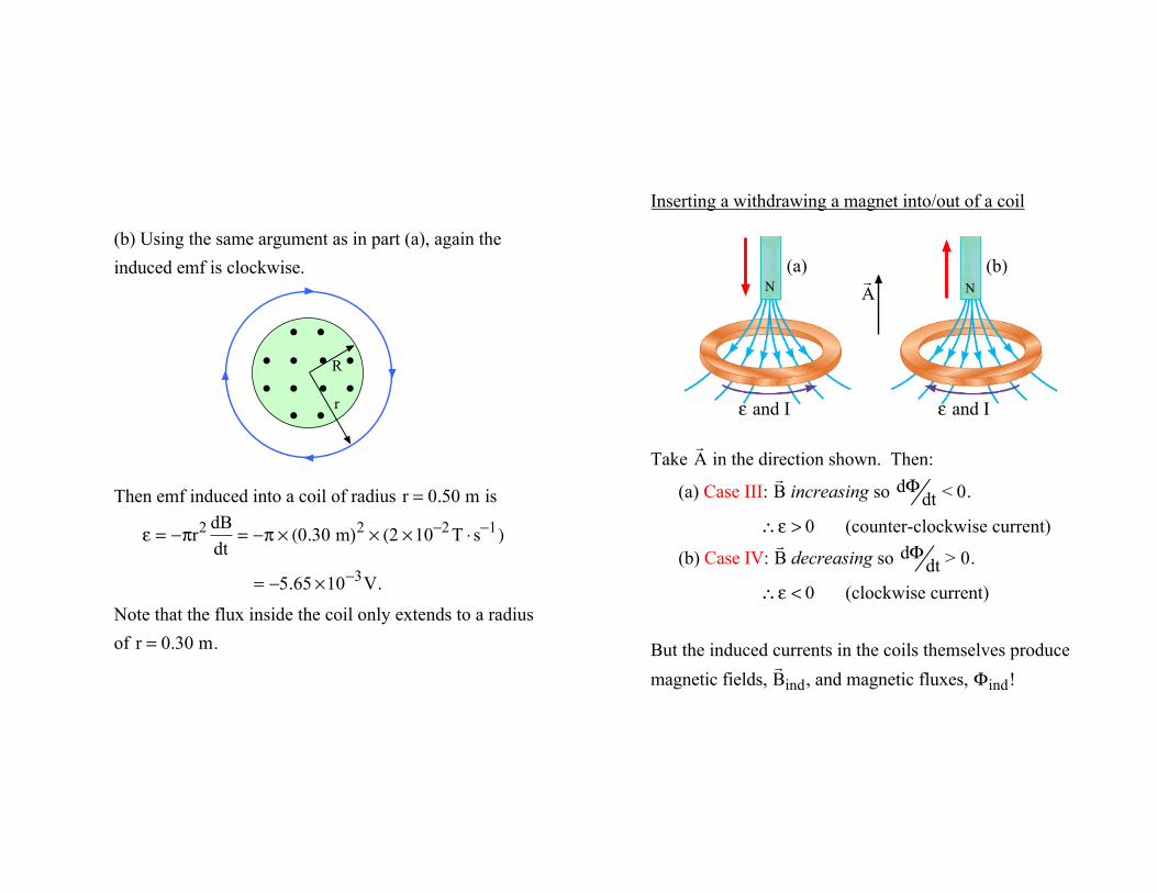
(b) Using the same argument as in part (a), again the induced emf is clockwise.
Then emf induced into a coil of radius r = 0.50 m is
ε = −πr2 dB
dt= −π × (0.30 m)2 × (2 ×10−2 T ⋅ s−1)
= −5.65 ×10⁻³V.
Note that the flux inside the coil only extends to a radius of r = 0.30 m.
• •
• •
• • • •• • • •
r
R
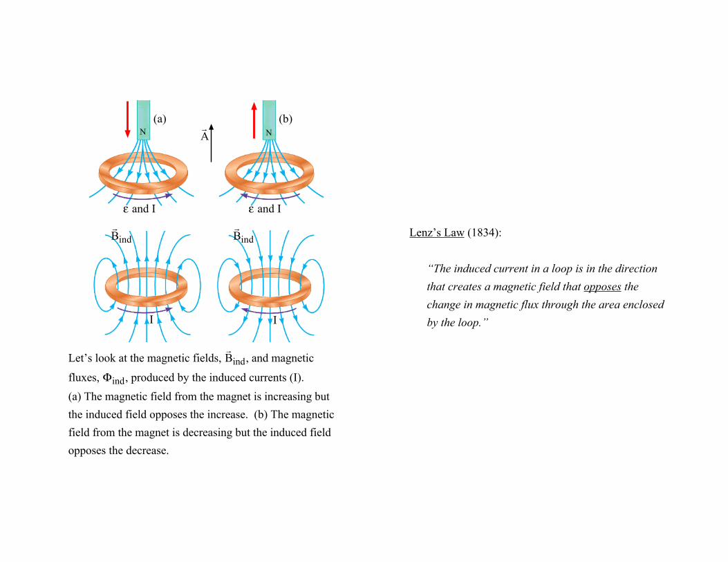
Inserting a withdrawing a magnet into/out of a coil
Take ! A in the direction shown. Then:
(a) Case III: ! B increasing so
dΦdt < 0.
∴ε > 0 (counter-clockwise current)
(b) Case IV: ! B decreasing so
dΦdt > 0.
∴ε < 0 (clockwise current)
But the induced currents in the coils themselves produce
magnetic fields, ! B ind, and magnetic fluxes, Φind!
N(a)
ε and I
N(b)
ε and I
! A
I
! B ind
I
! B ind
Let’s look at the magnetic fields, ! B ind, and magnetic
fluxes, Φind, produced by the induced currents (I).
(a) The magnetic field from the magnet is increasing but the induced field opposes the increase. (b) The magnetic field from the magnet is decreasing but the induced field opposes the decrease.
N(a)
ε and I
N(b)
ε and I
! A
Lenz’s Law (1834):
“The induced current in a loop is in the direction that creates a magnetic field that opposes the change in magnetic flux through the area enclosed by the loop.”
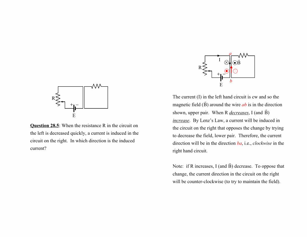
Question 28.5: When the resistance R in the circuit on the left is decreased quickly, a current is induced in the circuit on the right. In which direction is the induced current?
R
E
+ −The current (I) in the left hand circuit is cw and so the
magnetic field ( ! B ) around the wire ab is in the direction
shown, upper pair. When R decreases, I (and ! B )
increase. By Lenz’s Law, a current will be induced in the circuit on the right that opposes the change by trying to decrease the field, lower pair. Therefore, the current direction will be in the direction ba, i.e., clockwise in the right hand circuit.
Note: if R increases, I (and ! B ) decrease. To oppose that
change, the current direction in the circuit on the right will be counter-clockwise (to try to maintain the field).
R
E
+ −b
aI × •
! B
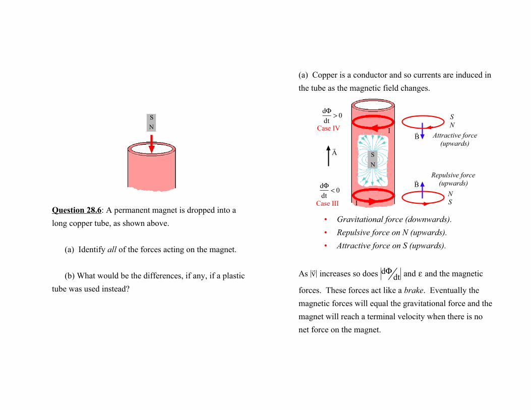
Question 28.6: A permanent magnet is dropped into a long copper tube, as shown above.
(a) Identify all of the forces acting on the magnet.
(b) What would be the differences, if any, if a plastic tube was used instead?
SN
(a) Copper is a conductor and so currents are induced in the tube as the magnetic field changes.
• Gravitational force (downwards).• Repulsive force on N (upwards).• Attractive force on S (upwards).
As ! v increases so does
dΦdt and ε and the magnetic
forces. These forces act like a brake. Eventually the magnetic forces will equal the gravitational force and the magnet will reach a terminal velocity when there is no net force on the magnet.
SN
I
I ! B
! B
SN
NS
Repulsive force(upwards)
Attractive force(upwards)
dΦdt
< 0
dΦdt
> 0
! A
Case IV
Case III
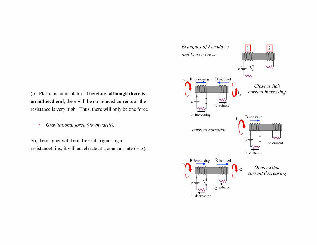
(b) Plastic is an insulator. Therefore, although there is an induced emf, there will be no induced currents as the resistance is very high. Thus, there will only be one force
• Gravitational force (downwards).
So, the magnet will be in free fall (ignoring air resistance), i.e., it will accelerate at a constant rate ( = g).
Examples of Faraday’sand Lenz’s Laws
ε
1 2
+−
I1 increasing
I2 induced
I1
I2
ε
! B increasing
! B induced
Close switchcurrent increasing
I1 constant
no current
I1
ε
! B constant
current constant
I1 decreasing
I2 induced
I1
I2
ε
! B decreasing
! B induced
Open switchcurrent decreasing
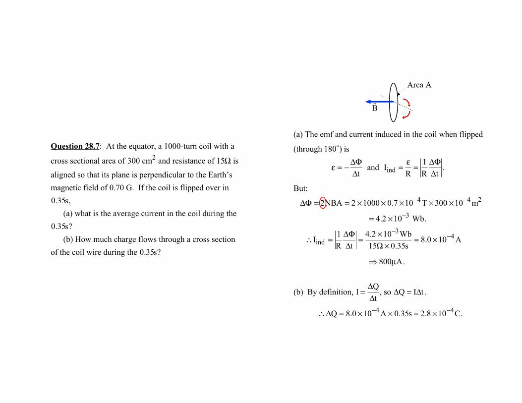
Question 28.7: At the equator, a 1000-turn coil with a
cross sectional area of 300 cm2 and resistance of 15Ω is
aligned so that its plane is perpendicular to the Earth’s magnetic field of 0.70 G. If the coil is flipped over in
0.35s,(a) what is the average current in the coil during the
0.35s?(b) How much charge flows through a cross section
of the coil wire during the 0.35s?
(a) The emf and current induced in the coil when flipped
(through 180!) is
ε = −
ΔΦΔt
and Iind =
εR=
1RΔΦΔt
.
But:
ΔΦ = 2NBA = 2 ×1000 × 0.7 ×10−4 T × 300 ×10−4 m2
= 4.2 ×10⁻³ Wb.
∴Iind =
1RΔΦΔt
=4.2 ×10⁻³Wb15Ω× 0.35s
= 8.0 ×10⁻⁴ A
⇒ 800µA.
(b) By definition, I =
ΔQΔt
, so ΔQ = IΔt .
∴ΔQ = 8.0 ×10−4 A × 0.35s = 2.8 ×10⁻⁴C.
" B
Area A
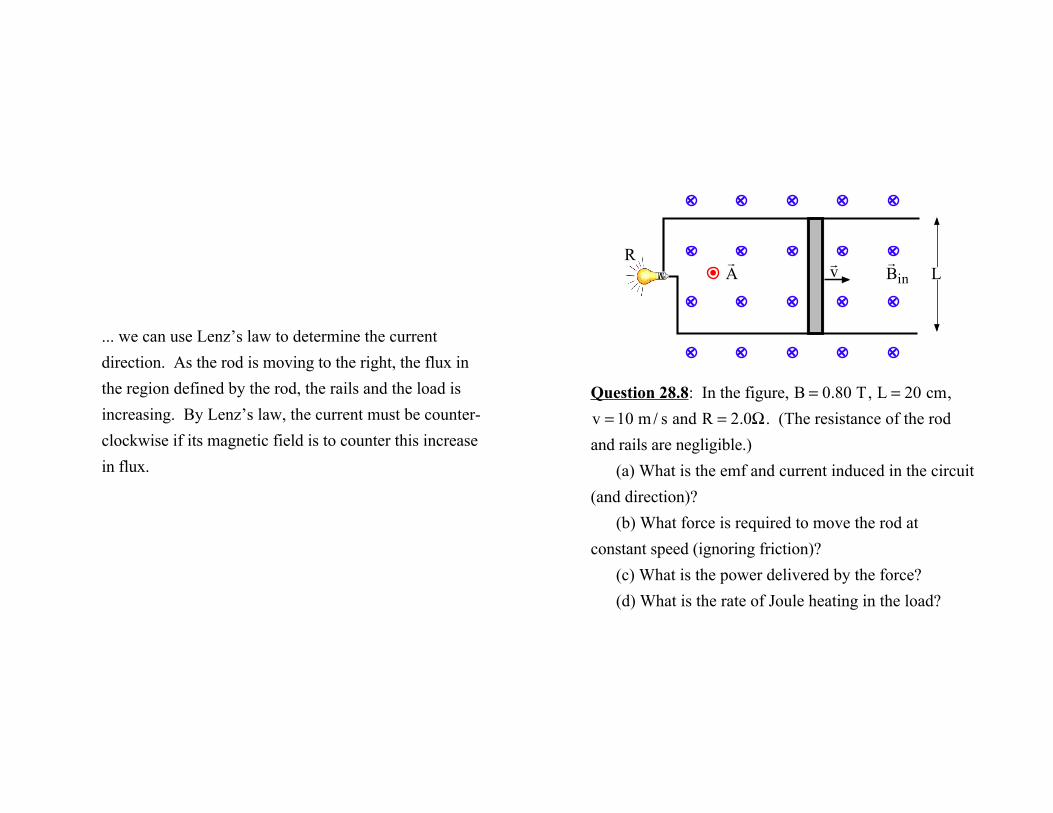
... we can use Lenz’s law to determine the current direction. As the rod is moving to the right, the flux in the region defined by the rod, the rails and the load is increasing. By Lenz’s law, the current must be counter-clockwise if its magnetic field is to counter this increase in flux.
Question 28.8: In the figure, B = 0.80 T, L = 20 cm,
v = 10 m / s and R = 2.0Ω. (The resistance of the rod and rails are negligible.)
(a) What is the emf and current induced in the circuit (and direction)?
(b) What force is required to move the rod at constant speed (ignoring friction)?
(c) What is the power delivered by the force?(d) What is the rate of Joule heating in the load?
! v
! A
R ! B in L
(a) Earlier, we found the emf induced is
ε = vBL =10 m/s × 0.80 T × 0.20 m = 1.60 V.
∴I =
εR
=1.60 V2.0Ω
= 0.80 A.
As the rod is moving to the right, the flux in the region defined by the rod, the rails and the load is increasing. By Lenz’s law, the current must be counter-clockwise if its magnetic field is to counter this increase in flux.
(b) The net force on the rod F∑ = Fapp − Fm = 0, where
Fapp is the applied force and Fm is the magnetic force.
∴Fapp = Fm = ILB (from earlier).
= 0.80 A × 0.20 m × 0.80 T = 0.128 N.
(c) From physics I, we know the power is P = Fappv
= 0.128 N ×10 m/s = 1.28 W.
(d) The rate of Joulian heating in the load is P = I2R
= (0.80 A)2 × 2.0Ω = 1.28 W.
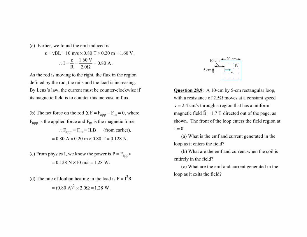
Question 28.9: A 10-cm by 5-cm rectangular loop, with a resistance of 2.5Ω moves at a constant speed
! v = 2.4 cm/s through a region that has a uniform
magnetic field ! B = 1.7 T directed out of the page, as
shown. The front of the loop enters the field region at
t = 0.(a) What is the emf and current generated in the
loop as it enters the field?(b) What are the emf and current when the coil is
entirely in the field?(c) What are the emf and current generated in the
loop as it exits the field?
10 cm
5 cm ! v
! B
20 cm
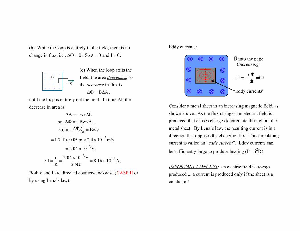
(b) While the loop is entirely in the field, there is no change in flux, i.e., ΔΦ = 0. So ε = 0 and I = 0.
(c) When the loop exits the field, the area decreases, so the decrease in flux is
ΔΦ = BΔA, until the loop is entirely out the field. In time Δt , the decrease in area is
ΔA = −wvΔt ,so ΔΦ = −BwvΔt .
∴ε = −ΔΦΔt = Bwv
= 1.7 T × 0.05 m × 2.4 ×10−2 m/s
= 2.04 ×10⁻³V.
∴I =
εR
=2.04 ×10⁻³V
2.5Ω= 8.16 ×10⁻⁴ A.
Both ε and I are directed counter-clockwise (CASE II or by using Lenz’s law).
! v
! B
Eddy currents:
Consider a metal sheet in an increasing magnetic field, as shown above. As the flux changes, an electric field is produced that causes charges to circulate throughout the metal sheet. By Lenz’s law, the resulting current is in a direction that opposes the changing flux. This circulating current is called an “eddy current”. Eddy currents can
be sufficiently large to produce heating ( P = i2R).
IMPORTANT CONCEPT: an electric field is always produced ... a current is produced only if the sheet is a conductor!
! B into the page
(increasing)
∴ε = −
dΦdt
⇒ i
“Eddy currents”
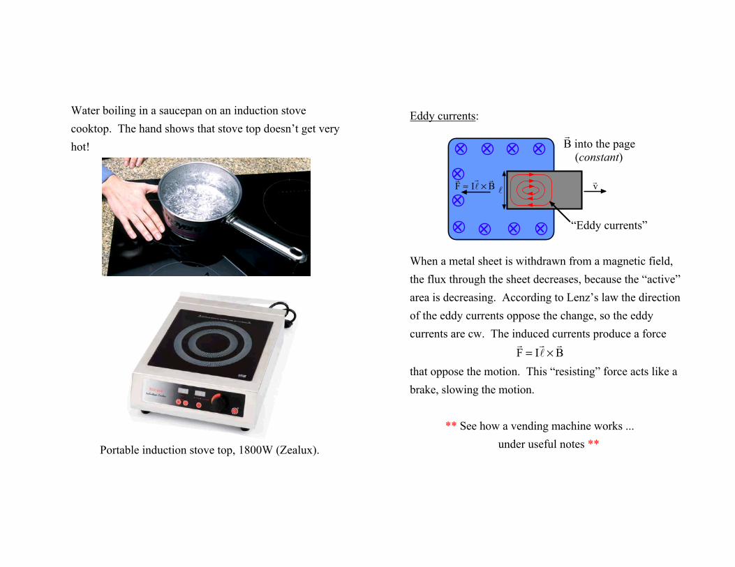
Water boiling in a saucepan on an induction stove cooktop. The hand shows that stove top doesn’t get very hot!
Portable induction stove top, 1800W (Zealux).
Eddy currents:
When a metal sheet is withdrawn from a magnetic field, the flux through the sheet decreases, because the “active” area is decreasing. According to Lenz’s law the direction of the eddy currents oppose the change, so the eddy currents are cw. The induced currents produce a force
! F = I! ℓ ×! B
that oppose the motion. This “resisting” force acts like a brake, slowing the motion.
** See how a vending machine works ...under useful notes **
! B into the page
(constant)
“Eddy currents”
! v
! F ≈ I! ℓ ×! B ℓ
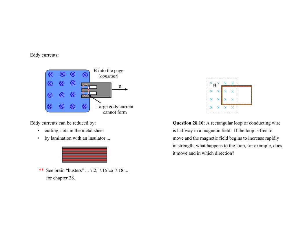
Eddy currents:
Eddy currents can be reduced by:• cutting slots in the metal sheet• by lamination with an insulator ...
** See brain “busters” ... 7.2, 7.15 ⇒ 7.18 ... for chapter 28.
! v
Large eddy currentcannot form
! B into the page
(constant)
Question 28.10: A rectangular loop of conducting wire is halfway in a magnetic field. If the loop is free to move and the magnetic field begins to increase rapidly in strength, what happens to the loop, for example, does it move and in which direction?
! B
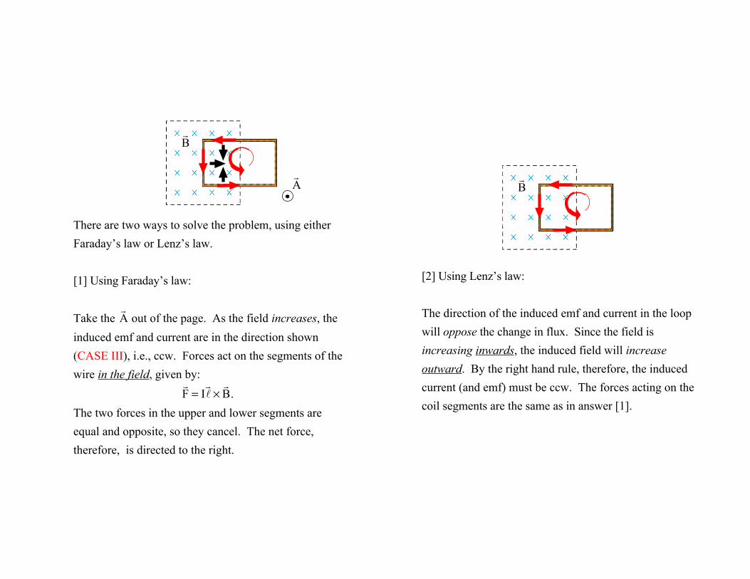
There are two ways to solve the problem, using either Faraday’s law or Lenz’s law.
[1] Using Faraday’s law:
Take the ! A out of the page. As the field increases, the
induced emf and current are in the direction shown (CASE III), i.e., ccw. Forces act on the segments of the wire in the field, given by:
! F = I! ℓ ×! B .
The two forces in the upper and lower segments are equal and opposite, so they cancel. The net force, therefore, is directed to the right.
! B
! A
[2] Using Lenz’s law:
The direction of the induced emf and current in the loop will oppose the change in flux. Since the field is increasing inwards, the induced field will increase outward. By the right hand rule, therefore, the induced current (and emf) must be ccw. The forces acting on the coil segments are the same as in answer [1].
! B
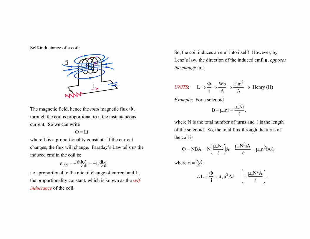
Self-inductance of a coil:
The magnetic field, hence the total magnetic flux Φ, through the coil is proportional to i, the instantaneous current. So we can write
Φ = Liwhere L is a proportionality constant. If the current changes, the flux will change. Faraday’s Law tells us the induced emf in the coil is:
εind = −dΦdt = −Ldi
dti.e., proportional to the rate of change of current and L, the proportionality constant, which is known as the self-inductance of the coil.
i
! B
+−
So, the coil induces an emf into itself! However, by Lenz’s law, the direction of the induced emf, ε, opposes the change in i.
UNITS: L⇒
Φi⇒
WbA
⇒T.m2
A⇒ Henry (H)
Example: For a solenoid
B = µ!ni =
µ!Niℓ
,
where N is the total number of turns and ℓ is the length of the solenoid. So, the total flux through the turns of the coil is
Φ = NBA = N
µ!Niℓ
⎛ ⎝
⎞ ⎠ A =
µ!N2iAℓ
= µ!n2iAℓ,
where n = Nℓ.
∴L =
Φi
= µ!n2Aℓ
=
µ!N2Aℓ
⎛
⎝ ⎜ ⎜
⎞
⎠ ⎟ ⎟ .
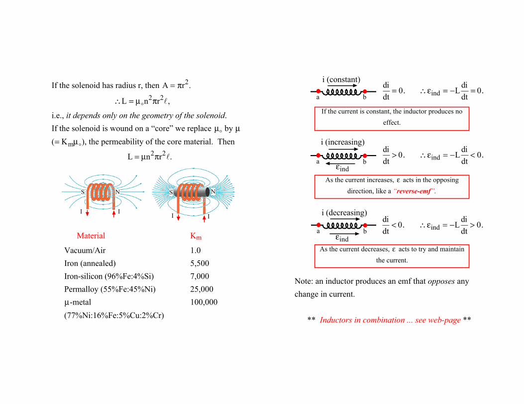
If the solenoid has radius r, then A = πr2.
∴L = µ!n2πr2ℓ,
i.e., it depends only on the geometry of the solenoid.If the solenoid is wound on a “core” we replace µ! by µ
( = Kmµ!), the permeability of the core material. Then
L = µn2πr2ℓ.
Material Km
Vacuum/Air 1.0Iron (annealed) 5,500Iron-silicon (96%Fe:4%Si) 7,000Permalloy (55%Fe:45%Ni) 25,000µ-metal 100,000
(77%Ni:16%Fe:5%Cu:2%Cr)
I I I I
N NSS
As the current increases, ε acts in the opposing
direction, like a “reverse-emf”.
i (constant)
a b
Note: an inductor produces an emf that opposes any change in current.
** Inductors in combination ... see web-page **
i (increasing)
εinda b
i (decreasing)
εinda b
As the current decreases, ε acts to try and maintain
the current.
If the current is constant, the inductor produces no
effect.
didt
= 0. ∴εind = −L
didt
= 0.
didt
> 0. ∴εind = −L
didt
< 0.
didt
< 0. ∴εind = −L
didt
> 0.
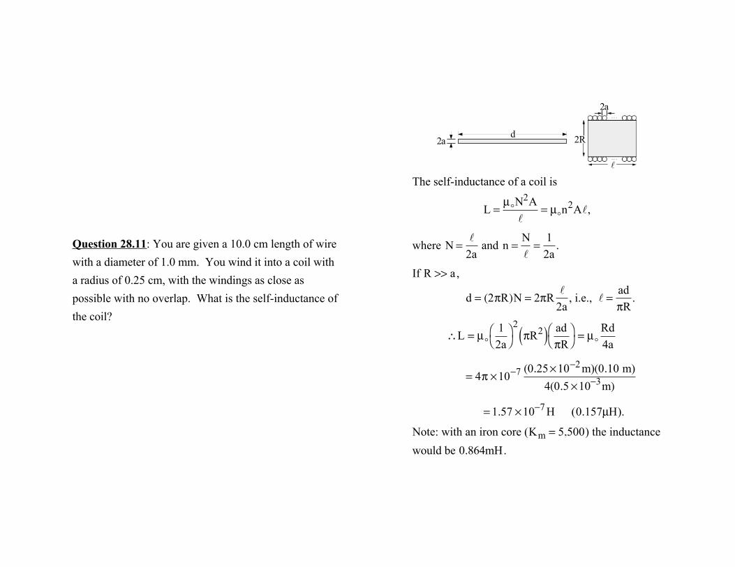
Question 28.11: You are given a 10.0 cm length of wire with a diameter of 1.0 mm. You wind it into a coil with a radius of 0.25 cm, with the windings as close as possible with no overlap. What is the self-inductance of the coil?
The self-inductance of a coil is
L =
µ!N2Aℓ
= µ!n2Aℓ,
where N =
ℓ2a
and n =
Nℓ
=1
2a.
If R >> a,
d = (2πR)N = 2πR
ℓ2a
, i.e., ℓ =
adπR
.
∴L = µ!
12a
⎛ ⎝
⎞ ⎠
2πR2( ) ad
πR⎛ ⎝
⎞ ⎠ = µ!
Rd4a
= 4π ×10−7 (0.25×10⁻² m)(0.10 m)
4(0.5 ×10⁻³m)
= 1.57 ×10⁻⁷ H ( 0.157µH).
Note: with an iron core ( Km = 5,500) the inductance would be 0.864mH.
2a d
ℓ
2R
2a
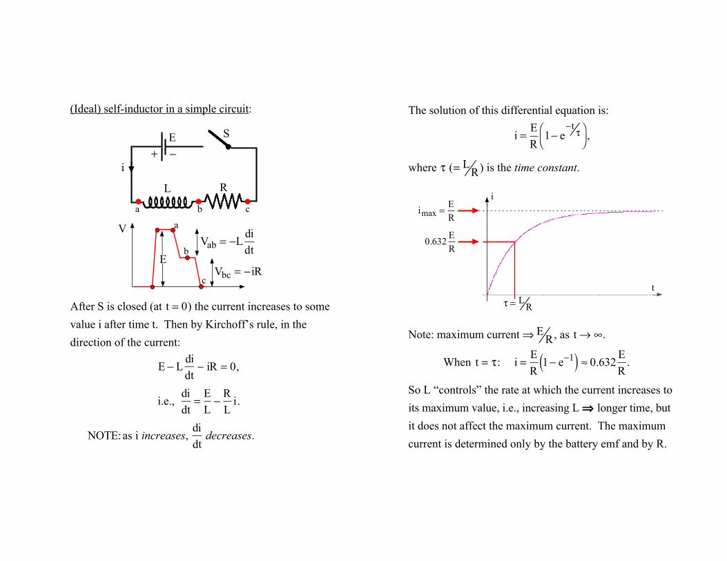
(Ideal) self-inductor in a simple circuit:
After S is closed (at t = 0) the current increases to some value i after time t. Then by Kirchoff’s rule, in the direction of the current:
E − L
didt
− iR = 0,
i.e., didt
=EL−
RL
i.
NOTE:as i increases, didt
decreases.
a
b
c
Vab = −L
didt
Vbc = −iR
V
E
S E
i
L R
a b c
+ −
The solution of this differential equation is:
i =
ER
1− e−t
τ⎛ ⎝
⎞ ⎠ ,
where τ ( =L
R) is the time constant.
Note: maximum current ⇒E
R, as t → ∞.
When t = τ: i =
ER
1− e−1( ) ≈ 0.632ER
.
So L “controls” the rate at which the current increases to its maximum value, i.e., increasing L ⇒ longer time, but it does not affect the maximum current. The maximum current is determined only by the battery emf and by R.
imax = E
R
i
t
τ = LR
0.632
ER
Rate at which energy supplied by batteryto the circuit
Ei
Rate energy supplied to R i2R
Rate energy supplied to L
Li
didt
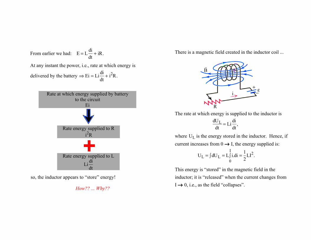
From earlier we had: E = L
didt
+ iR.
At any instant the power, i.e., rate at which energy is
delivered by the battery ⇒ Ei = Li
didt
+ i2R.
so, the inductor appears to “store” energy!
How?? ... Why??
There is a magnetic field created in the inductor coil ...
The rate at which energy is supplied to the inductor is
dULdt
= Lididt
,
where UL is the energy stored in the inductor. Hence, if current increases from 0 → I, the energy supplied is:
UL = dUL∫ = L i.di
0
I∫ =
12
LI2.
This energy is “stored” in the magnetic field in the inductor; it is “released” when the current changes from I → 0, i.e., as the field “collapses”.
i
! B
+−ε
R
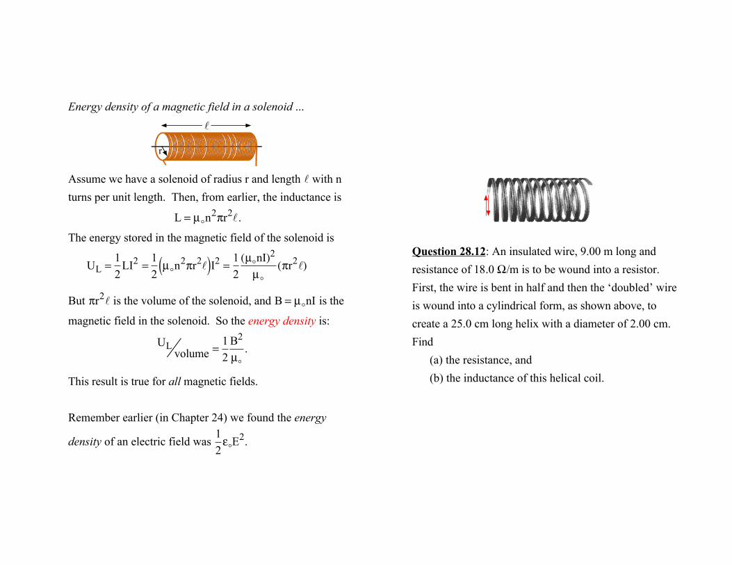
Energy density of a magnetic field in a solenoid ...
Assume we have a solenoid of radius r and length ℓ with n turns per unit length. Then, from earlier, the inductance is
L = µ"n2πr2ℓ.
The energy stored in the magnetic field of the solenoid is
UL =
12
LI2 =12µ"n
2πr2ℓ( )I2 =12(µ"nI)2
µ"(πr2ℓ)
But πr2ℓ is the volume of the solenoid, and B = µ"nI is the
magnetic field in the solenoid. So the energy density is:
ULvolume =
12
B2
µ".
This result is true for all magnetic fields.
Remember earlier (in Chapter 24) we found the energy
density of an electric field was 12ε"E
2.
ℓ
r
Question 28.12: An insulated wire, 9.00 m long and resistance of 18.0 Ω/m is to be wound into a resistor. First, the wire is bent in half and then the ‘doubled’ wire is wound into a cylindrical form, as shown above, to create a 25.0 cm long helix with a diameter of 2.00 cm.Find
(a) the resistance, and (b) the inductance of this helical coil.
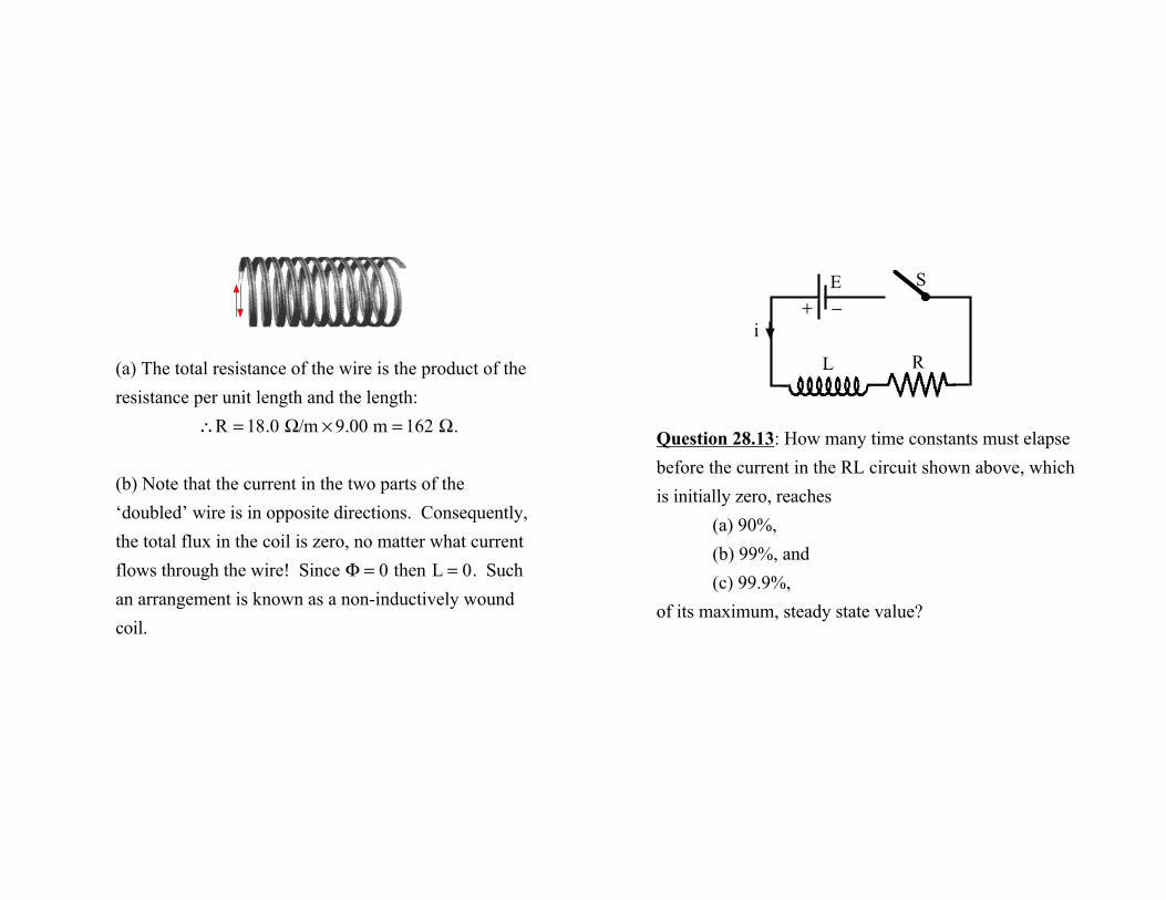
(a) The total resistance of the wire is the product of the resistance per unit length and the length:
∴R = 18.0 Ω/m × 9.00 m = 162 Ω.
(b) Note that the current in the two parts of the ‘doubled’ wire is in opposite directions. Consequently, the total flux in the coil is zero, no matter what current flows through the wire! Since Φ = 0 then L = 0. Such an arrangement is known as a non-inductively wound coil.
Question 28.13: How many time constants must elapse before the current in the RL circuit shown above, which is initially zero, reaches
(a) 90%,(b) 99%, and(c) 99.9%,
of its maximum, steady state value?
S E
i
L R
+ −
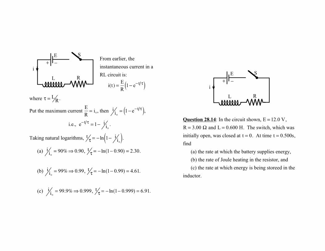
From earlier, the instantaneous current in a RL circuit is:
i(t) = E
R1− e− t τ( )
where τ =L
R.
Put the maximum current ER= i!, then
ii!= 1− e− t τ( ),
i.e., e− t τ = 1− i
i!.
Taking natural logarithms, tτ = − ln 1− i
i!( ).(a)
ii!= 90%⇒ 0.90,
tτ = − ln 1− 0.90( ) = 2.30.
(b) ii!= 99%⇒ 0.99,
tτ = − ln 1− 0.99( ) = 4.61.
(c) ii!= 99.9%⇒ 0.999,
tτ = − ln 1− 0.999( ) = 6.91.
S E
i
L R
+ −
Question 28.14: In the circuit shown, E = 12.0 V,
R = 3.00 Ω and L = 0.600 H. The switch, which was initially open, was closed at t = 0. At time t = 0.500s, find
(a) the rate at which the battery supplies energy,(b) the rate of Joule heating in the resistor, and(c) the rate at which energy is being storeed in the
inductor.
S E
i
L R
+ −
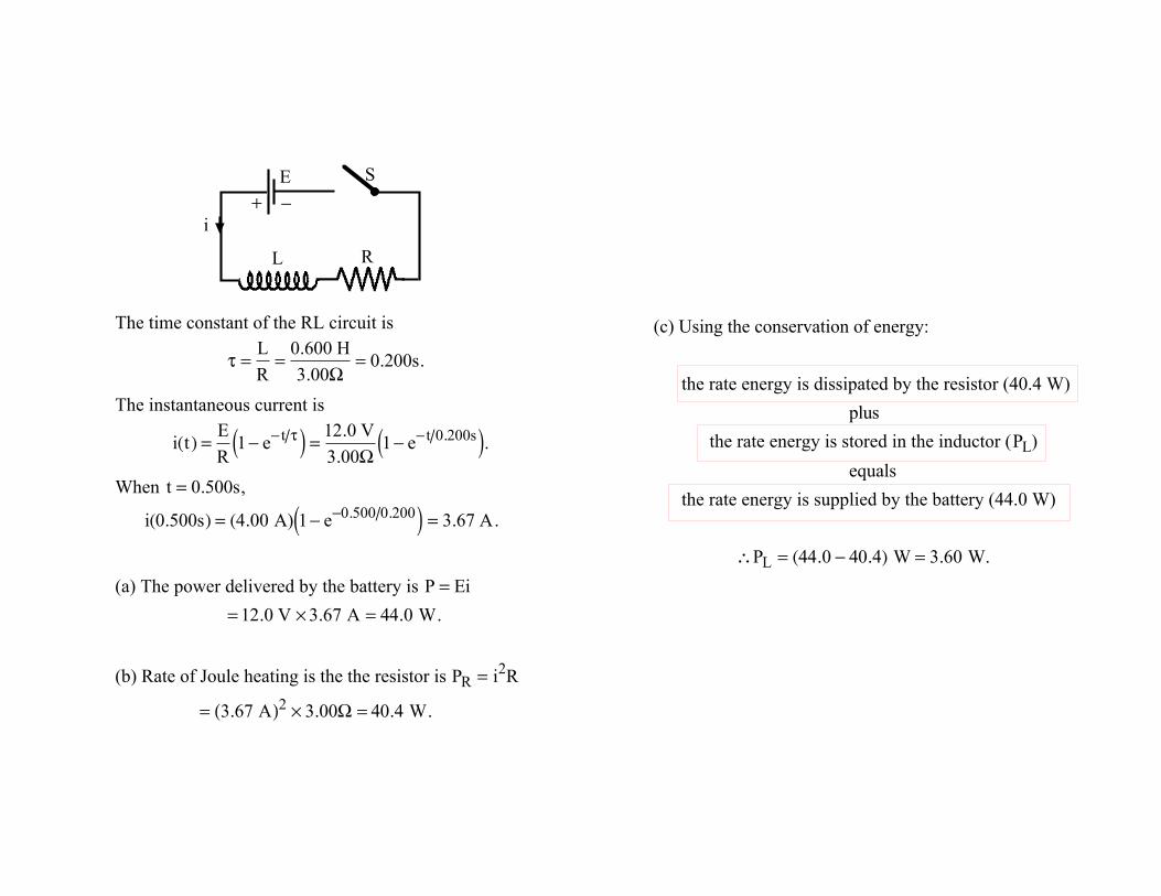
The time constant of the RL circuit is
τ =
LR
=0.600 H3.00Ω
= 0.200s.
The instantaneous current is
i(t) = E
R1− e− t τ( ) = 12.0 V
3.00Ω1− e− t 0.200s( ).
When t = 0.500s,
i(0.500s) = (4.00 A) 1− e−0.500 0.200( ) = 3.67 A.
(a) The power delivered by the battery is P = Ei
= 12.0 V × 3.67 A = 44.0 W.
(b) Rate of Joule heating is the the resistor is PR = i2R
= 3.67 A( )2 × 3.00Ω = 40.4 W.
S E
i
L R
+ −
(c) Using the conservation of energy:
the rate energy is dissipated by the resistor (40.4 W)plus
the rate energy is stored in the inductor ( PL)
equalsthe rate energy is supplied by the battery (44.0 W)
∴PL = (44.0 − 40.4) W = 3.60 W.