Embed Size (px)
Citation preview
Chapter 24: Thin FilmsDiffraction
Diffraction Grating

Hint: Be able to do the homework (both theproblems to turn in AND the recommended ones)you’ll do fine on the exam!
Wednesday, February 3, 1999 in class
Ch. 22, 23, 24 (Sect. 1-6)
You may bring one 3”X5” index card (hand-writtenon both sides), a pencil or pen, and a scientificcalculator with you.

DUE TODAY11 pm

For the case of a thin film of index of refractionn surrounded by air, the maxima and minimaoccur under the following conditions
2 1
2t m n ( ) Constructive interference
2t m n Destructive interference

Air, n = 1
Water, n = 1.33
Glass, n = 1.5
t
In this case, the blue and redrays suffer a 180o phasechange, so the conditionsfor maxima and minima areexactly the opposite of whatappears on the last slide!

When working problems with thin films, you must first evaluate what happens to the reflected ray at each boundary.
For rays travelling from low n to high n, a 180o phase shift will occur. Then, simply calculate the difference in path length based upon the thickness of the film.

For cases in which both reflected rays sufferthe same fate (either phase shifted or not), pathlength differences of 1/2 a wavelength lead todestructive interference.
For cases in which one reflected ray suffersa phase shift of half a wavelength, path lengthdifferences of 1 full wavelength lead todestructive interference.


In studying the two slit interference pattern,we’ve made some simplifying assumptionsand neglected some important physicalprocesses.
Perhaps the most important of these isknown as
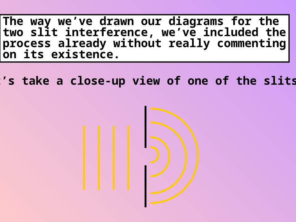
The way we’ve drawn our diagrams for thetwo slit interference, we’ve included theprocess already without really commentingon its existence.
Let’s take a close-up view of one of the slits...

If light is travelling in a straight path, whydon’t we observe the following:

Geometric optics cannot explain the diffraction--the bending of light around edges--that isactually observed in our experiments withthe slits)
When we project the light passing througha single slit onto a distant screen, guess whatwe see….

Centralmaximum Secondary maxima
112 2
Secondary minima

Right about this point, you should be askingyourself...
Why in the world should light from a single slit produce what looks like an interference pattern on the screen????
It is useful to employ Huygens’ principleto explain our observations...

Recall that Huygens’ principle advised us totreat each portion of a wave front of lightas a source of light waves...
screen
Thinking about the problemthis way allows us to see thesingle slit as containing alarge number of sources,each of which can interfere.

screen
a
a
2sin
A dark spot will appear on the screen atlocations where the path length difference is half a wavelength.
2
minima

screen
a
a
2sin
2
minima
This is true for any pair of “sources” separatedby half the slit width...

Destructive interference will occur aslong as the path length difference is someintegral multiple of the quantity /a
Therefore, angles at which destructiveinterference occurs are given by
sin m
aWhere m = +/- 1, +/- 2, +/- 3, ….

As with the two-slit interference pattern,we can relate the distance above the centralmaximum of each dark fringe with a littlegeometry...
screen
a
L
y
sin tan
y
L am

sin tan
y
L am
Notice that when the slit width, a, is less than the wavelength , the quantity on the right side is greater than 1!
Therefore, for a < , we will not observe the diffraction interference pattern.

The secondary maxima can be found on eitherside of the central maximum approximatelyhalf-way between the locations of successiveminima. The central maximum is found atthe angle = 0 and the secondary maximaat angles given by:
sin tan ( )
y
L am 1
2
Note that the central maximum is twiceas wide as the secondary maxima.

The formulae for the diffraction pattern looka lot like those we saw for the two-slitinterference pattern, but they are verydifferent!
sin m
a
diffraction minima
sin m
d
Two-slit maxima


Conceptually, it’a quite simple to extend ourdiscussion of diffraction and Young’sexperiment to the case of the interferencepattern produced from an object known as a
Instead of the large number of “sources”that we considered in the diffraction patternusing Huygen’s principle, the diffractiongrating consists of a very large number ofslits, each one of which acts as its ownsource.
You can think of it as an n-slit interferencepattern (where n is the number of slits).

DiffractionGrating
Diffraction gratings are usually describedby the number of slits per unit length.
L N slits
As in Young’s experiment, the observeddiffraction pattern depends upon the slitseparation, the wavelength of the incidentlight, and the angle to the screen.

observed interference pattern
0 1-1-2 2
centralmaximum
orderof the
secondarymaxima
We can proceed as before (using geometry) to locate the maxima.
Notice thatthese linestend to bevery narrow.

sin m
d
N-slit maximaWhere m is the order numberand d the slit separation, givenby L / N for the diffractiongrating.
As you will see in the laboratory, diffractiongratings provide a great way to separatethe constituent wavelengths of incident light,since each wavelength will have a uniqueangle for the appearance of bright lineswhen examined through the grating.
All wavelengths will have a bright at angle = 0, so a bright white line will appear atthis angle (usually).

Geometric OpticsMirrorsLensesImages
InterferenceDiffraction

c f The wavelength () and frequency (f) of electromagnetic waves are related to their propagation speeds by
10-9 10-6 10-3 1 103
TVTV
Microwaves
Infrared
VISIBLE
Ultra-Violet
X-ray
c = 3 X 10⁸ m/s

i r
i r
(a.k.a. Snell’s Law)
n n1 1 2 2sin sin
i r air
waterr
n1
n2

The frequency with which waves leave one medium must equal the frequency with which they enter another (otherwise we’d have waves piling up at a boundary, and we never observe that to occur).
c v
nc
speed of light in vacuum
speed of light in medium v
n n1 1 2 2 Since the frequency of the light must be the same in both media, it’s the wavelength that is changing
n1
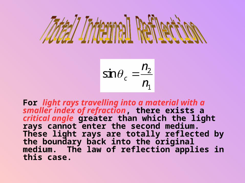
For light rays travelling into a material with a smaller index of refraction, there exists a critical angle greater than which the light rays cannot enter the second medium. These light rays are totally reflected by the boundary back into the original medium. The law of reflection applies in this case.
sin cn
n 2
1

Let’s start by studying what happens whenlight strikes a plane mirror (a 2D surface)..
pthe distanceof the object
from the mirror
qthe distanceof the image
from the mirror
h = h’ p = q
hobjectheight
object imageh’
imageheight
Mh
h
'Magnification

Concave:
Convex:
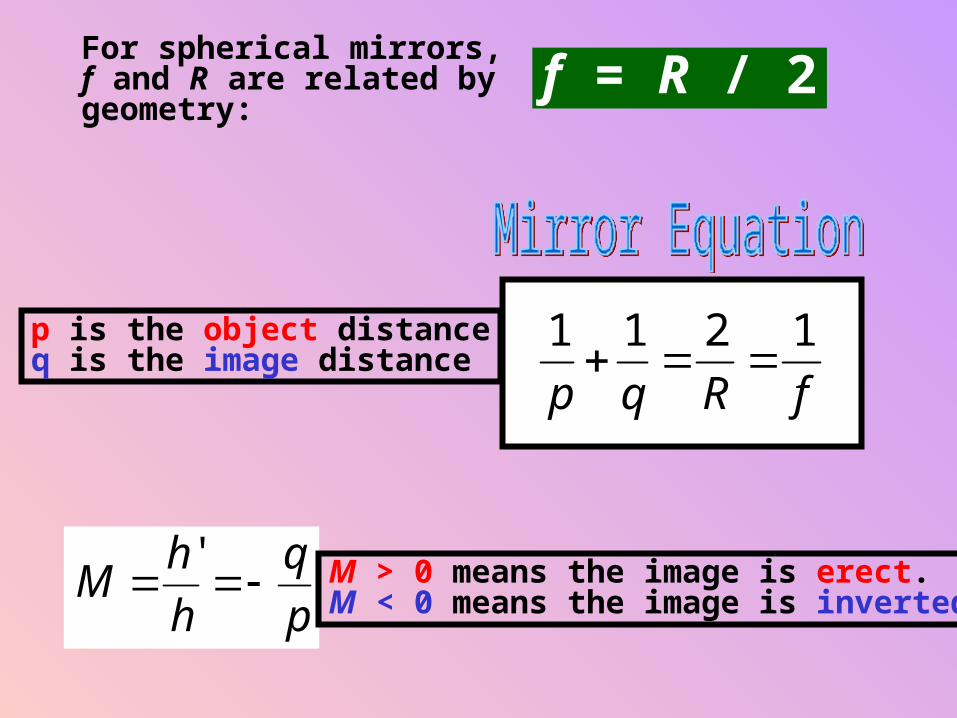
For spherical mirrors, f and R are related by geometry: f = R / 2
Mh
h
q
p
' M > 0 means the image is erect.M < 0 means the image is inverted.
1 1 2 1
p q R f
p is the object distanceq is the image distance

n1
n2
objectimage
n
p
n
q
n n
R1 2 2 1
p is the distance of the object from the surface
q is the distance of the image from the surface
Mh
h
n q
n p
' 1
2

A plane has a radius of curvature equal to infinity, so...
n
p
n
q
n n1 2 2 1 0
n
p
n
q1 2
Diverging (f < 0)Thinnest in the middle.Parallel light rays frominfinity diverge as theypass through the lens.
Converging (f > 0)Thickest in the middle.Bring light rays frominfinity to a focus on theopposite side of the lens.

Light can pass through a lens in either direction. So it’s not surprising that alens will have two foci.
focal length, f
The thin lens equation relates the object and image distances to the focal length.
1 1 1
p q f
11
1 1
1 2fn
R R
FHG
IKJ( ) R2 R1
front
back

front
back
“focusof back
surface”
“focusof front
surface”
IMAGE
OBJECT
Converging lens
Mh
h
q
p
'

Whether you’re dealing with mirrors, refracting surfaces, or lenses, p and q are defined to be positive where the light rays actually are.
Real objects will have p > 0.Real images will have q > 0.
Virtual objects will have p < 0.Virtual images will have q < 0.

To determine the sign of R correctly,examine where the light ray goes AFTERencountering the surface...
For a lens, the light passesthrough to the back side...
q > 0q < 0
R < 0
For a mirror, the lightreflects back on thesame side...q < 0R > 0 q > 0
f > 0

1) To determine whether p > 0 or p < 0, askyourself, “Where is the light coming from?”On the side of the boundary from which lightcomes, p > 0!
2) To determine whether q > 0 or q < 0, askyourself, “Where does the light go?” On theside of the boundary that light travels afterencountering the surface, q > 0.

monochromaticlight source
crests
troughs
bright
dark
Two-slitinterference
pattern
Observedinterference
pattern

d screen
L
yr1
r 2
r r d2 1 sin
For small
sin tan y
L
So,
dy
L d msin
bright fringes
d msin ( )1
2
dark fringes

When light reflects off theboundary of a material with a higher index of refraction than that in which the light is incident on the surface, thisphase shift of 180o will occur.
mirror, n > 1
incident
crest trough
reflected
Air, n = 1
If the reflected rays lie on top of one another (as will be the case if the light is normally incident on the top surface), the reflected rays can interfere with one another!
Air, n = 1
Water, n = 1.33
Air, n = 1
t

The path length difference is 2 t
2 1
2t m n ( )constructive
2t m n destructive
When working problems with thin films, you must first evaluate what happens to the reflected ray at each boundary. For rays travelling from low n to high n, a 180o phase shift will occur. Then, simply calculate the difference in path length based upon the thickness of the film.
For cases in which both reflected rays suffer the same fate (either phase shifted or not), path length differences of 1/2 a wavelength lead to destructive interference.
For cases in which one reflected ray suffers a phase shift of half a wavelength, path length differences of 1 full wavelength lead to destructive interference.