Embed Size (px)
Citation preview
CHAPTER 2
MAGNETIC MATERIALS
AND CIRCUITS
Describe, Explain and Calculate fundamental of electricity, magnetism and circuits
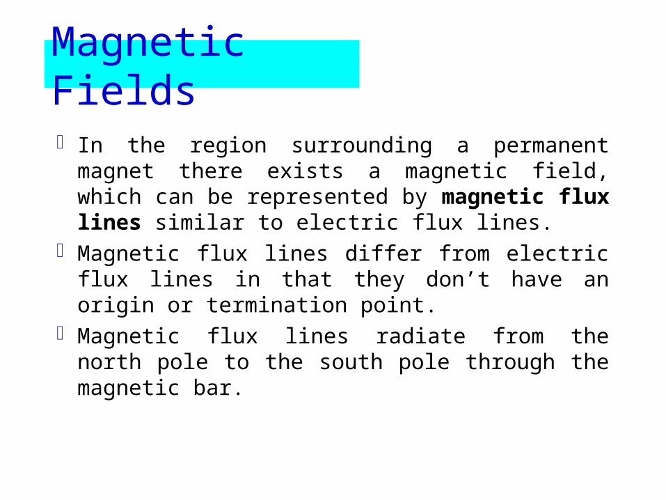
Magnetic Fields
In the region surrounding a permanent magnet there exists a magnetic field, which can be represented by magnetic flux lines similar to electric flux lines.
Magnetic flux lines differ from electric flux lines in that they don’t have an origin or termination point.
Magnetic flux lines radiate from the north pole to the south pole through the magnetic bar.
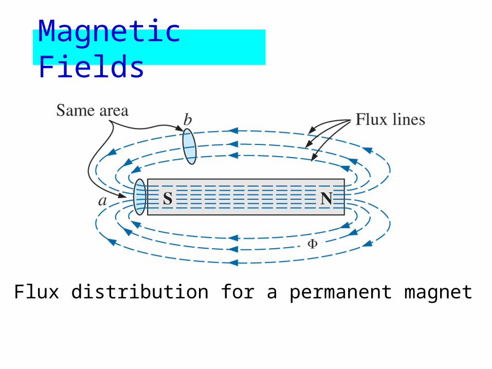
Flux distribution for a permanent magnet
Magnetic Fields
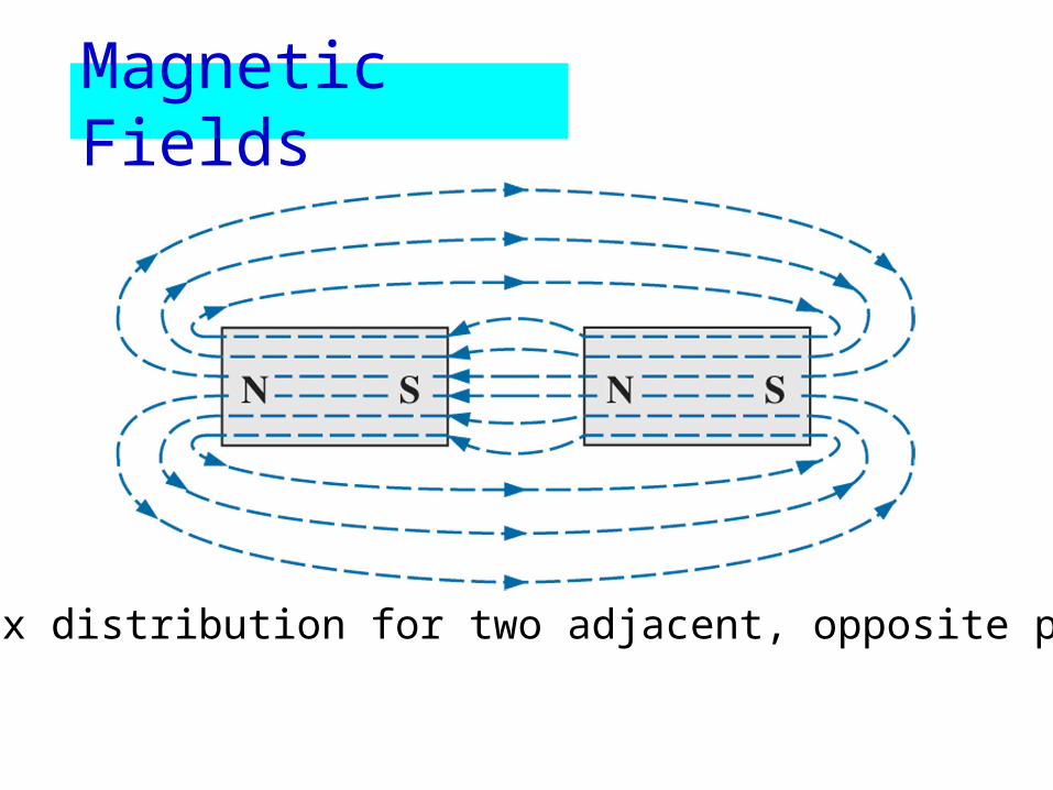
Flux distribution for two adjacent, opposite poles
Magnetic Fields
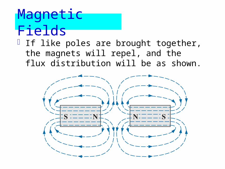
If like poles are brought together, the magnets will repel, and the flux distribution will be as shown.
Magnetic Fields
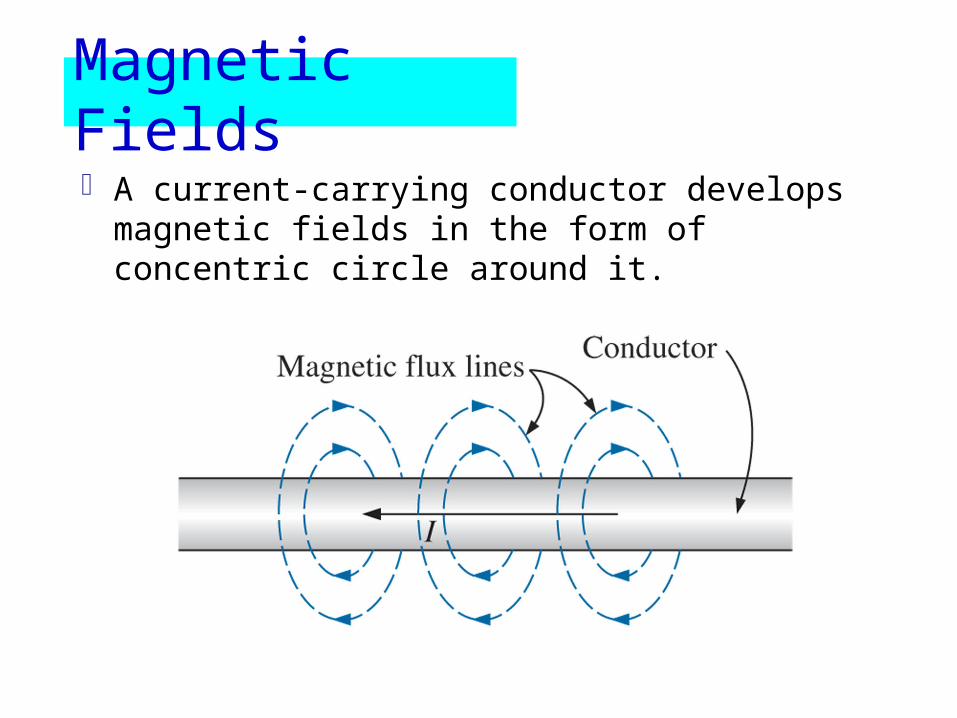
A current-carrying conductor develops magnetic fields in the form of concentric circle around it.
Magnetic Fields
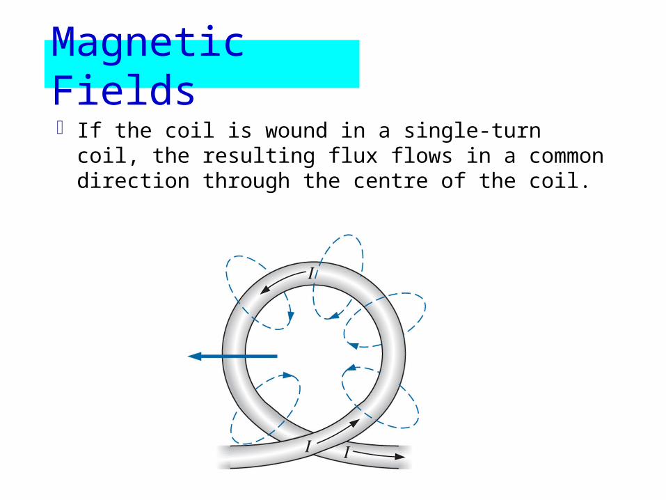
If the coil is wound in a single-turn coil, the resulting flux flows in a common direction through the centre of the coil.
Magnetic Fields

A coil of more than one turn produces a magnetic field that exists in a continuous path through and around the coil.
Magnetic Fields
The flux distribution around the coil is quite similar to the permanent magnet.
The flux lines leaving the coil from the left and entering to the right simulate a north and a south pole.
The concentration of flux lines in a coil is less than that of a permanent magnet.
Magnetic Fields
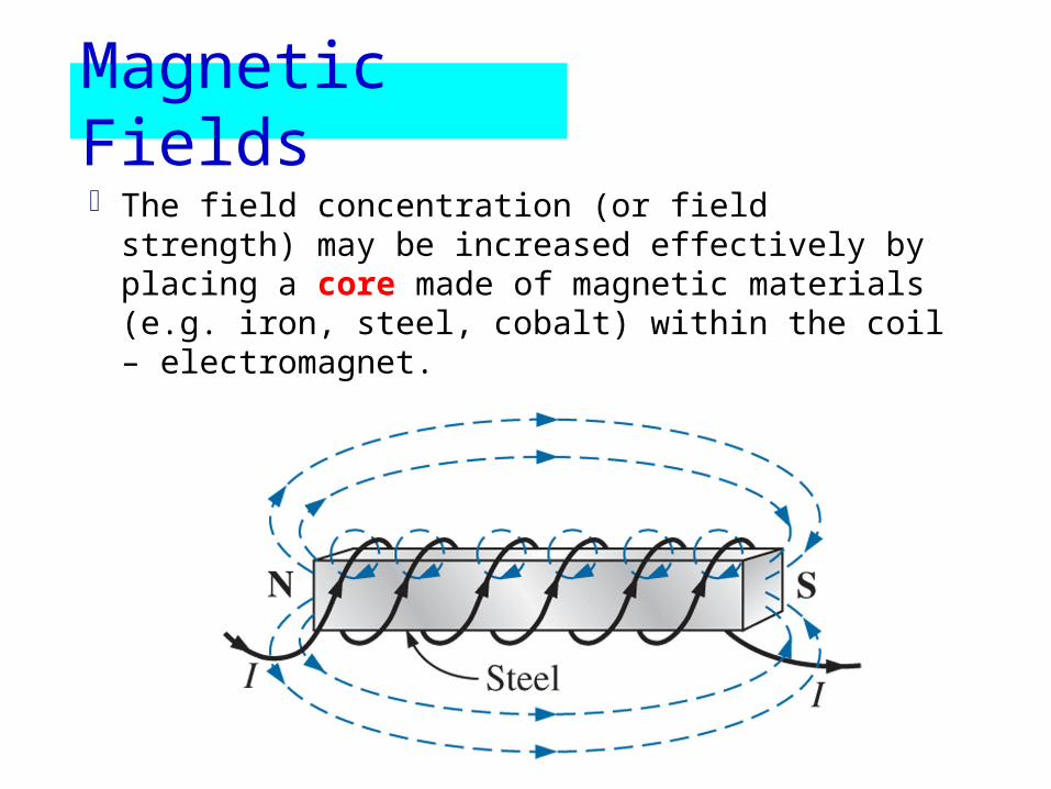
The field concentration (or field strength) may be increased effectively by placing a core made of magnetic materials (e.g. iron, steel, cobalt) within the coil – electromagnet.
Magnetic Fields
The field strength of an electromagnet can be varied by varying one of the component values (i.e. currents, turns, material of the core etc.)
Magnetic Fields

The direction of the magnetic flux lines can be found by placing the thumb of the right hand in the direction of conventional current flow and noting the direction of the fingers (commonly called the right hand rule).
Magnetic Fields
Flux and Flux Density
In the SI system of units, magnetic flux is measured in webers (Wb) and is represented using the symbol
Magnetic Fields
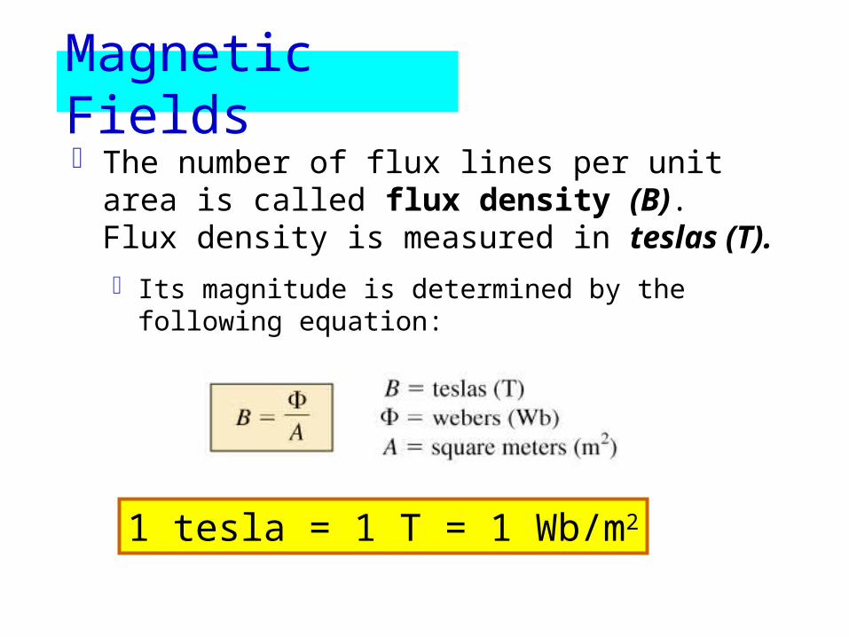
The number of flux lines per unit area is called flux density (B). Flux density is measured in teslas (T).
Its magnitude is determined by the following equation:
1 tesla = 1 T = 1 Wb/m2
Magnetic Fields
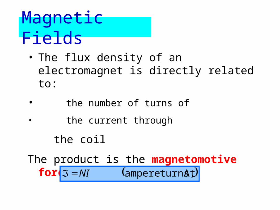
• The flux density of an electromagnet is directly related to:
• the number of turns of
• the current through
the coil
The product is the magnetomotive force:
At turns,-ampereNI
Magnetic Fields
PermeabilityAnother factor affecting the field strength is
the type of core used.
If cores of different materials with the same physical dimensions are used in the electromagnet, the strength of the magnet will vary in accordance with the core used.
The variation in strength is due to the number of flux lines passing through the core.
Magnetic Fields
Magnetic material is material in which flux lines can readily be created and is said to have high permeability.
Permeability () is a measure of the ease with which magnetic flux lines can be established in the material.
Magnetic Fields

Permeability of free space 0 (vacuum) is
Materials that have permeability slightly less than that of free space are said to be diamagnetic and those with permeability slightly greater than that of free space are said to be paramagnetic.
Wb/A.m104 7 o
Magnetic Fields
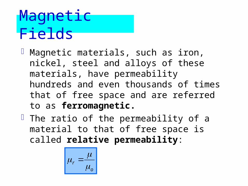
Magnetic materials, such as iron, nickel, steel and alloys of these materials, have permeability hundreds and even thousands of times that of free space and are referred to as ferromagnetic.
The ratio of the permeability of a material to that of free space is called relative permeability:
or
Magnetic Fields
In general for ferromagnetic materials,
For nonmagnetic materials,
Relative permeability is a function of operating conditions.
100r
1r
Magnetic Fields

ReluctanceThe resistance of a material to the flow of
charge (current) is determined for electric circuits by the equation
The reluctance of a material to the setting up of magnetic flux lines in a material is determined by the following equation
A
l
A
lR
At/Wbor rels,A
l
tyconductivi
1
Ohm’s Law for Magnetic Circuits
opposition
causeeffect
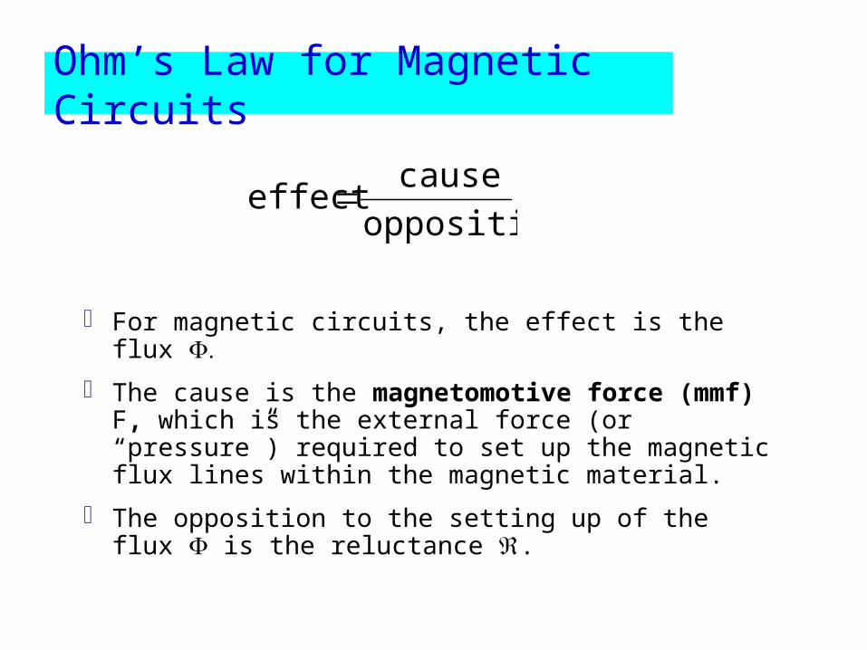
For magnetic circuits, the effect is the flux
The cause is the magnetomotive force (mmf) F, which is the external force (or “pressure”) required to set up the magnetic flux lines within the magnetic material.
The opposition to the setting up of the flux is the reluctance .
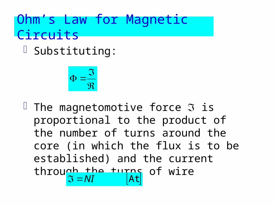
Substituting:
The magnetomotive force is proportional to the product of the number of turns around the core (in which the flux is to be established) and the current through the turns of wire
AtNI
Ohm’s Law for Magnetic Circuits
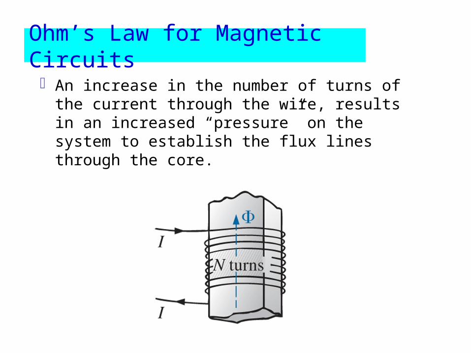
An increase in the number of turns of the current through the wire, results in an increased “pressure” on the system to establish the flux lines through the core.
Ohm’s Law for Magnetic Circuits
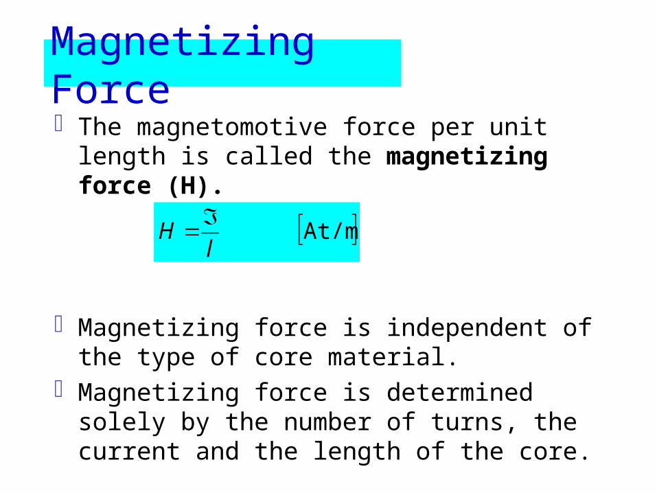
Magnetizing ForceThe magnetomotive force per unit length is
called the magnetizing force (H).
Magnetizing force is independent of the type of core material.
Magnetizing force is determined solely by the number of turns, the current and the length of the core.
At/ml
H
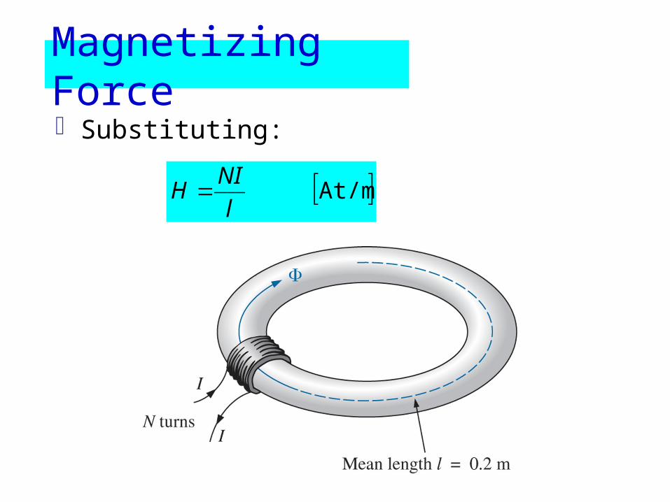
Substituting:
At/ml
NIH
Magnetizing Force

The flux density and the magnetizing force are related by the equation:
HB
Magnetizing Force
Hysteresis
Hysteresis – The lagging effect between the flux density of a material and the magnetizing force applied.
The curve of the flux density (B) versus the magnetic force (H) is of particular interest to engineers.
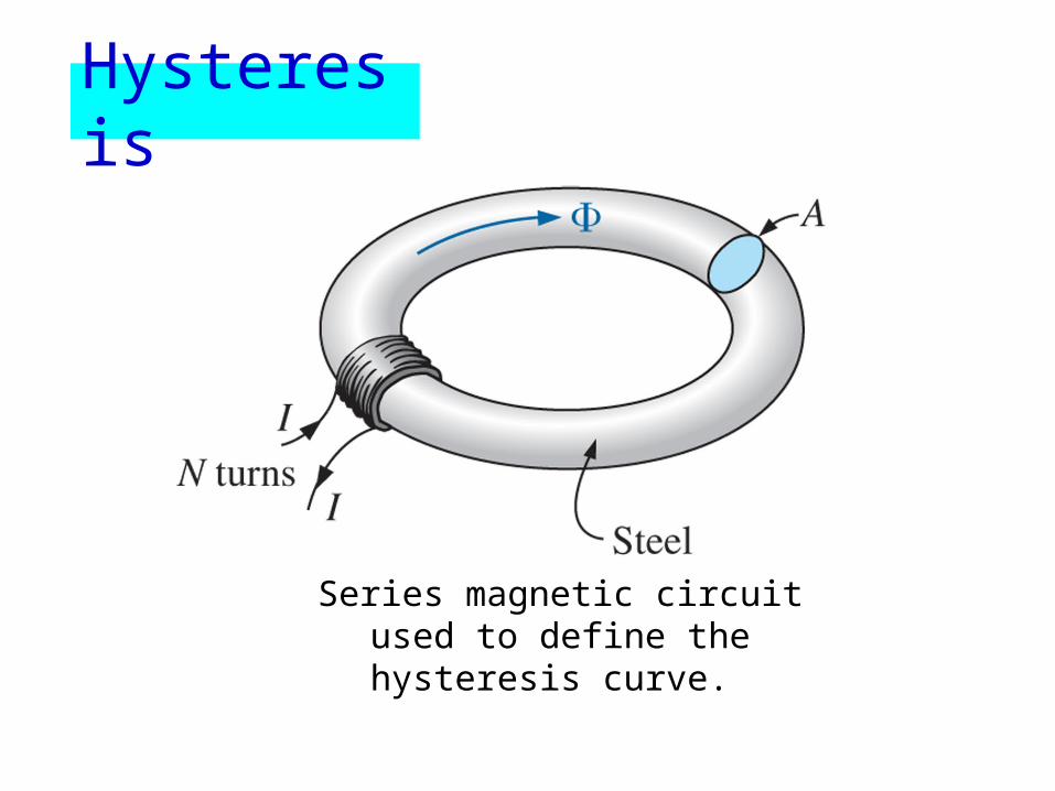
Series magnetic circuit used to define the hysteresis curve.
Hysteresis

The entire curve (shaded) is called the hysteresis curve.
The flux density B lagged behind the magnetizing force H during the entire plotting of the curve. When H was zero at c, B was not zero but had only begun to decline. Long after H had passed through zero and had equaled to –Hd did the flux density B finally become equal to zero
Hysteresis
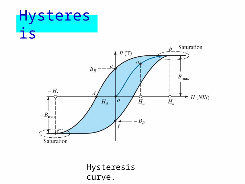
Hysteresis curve.
Hysteresis

If the entire cycle is repeated, the curve obtained for the same core will be determined by the maximum H applied.
Hysteresis
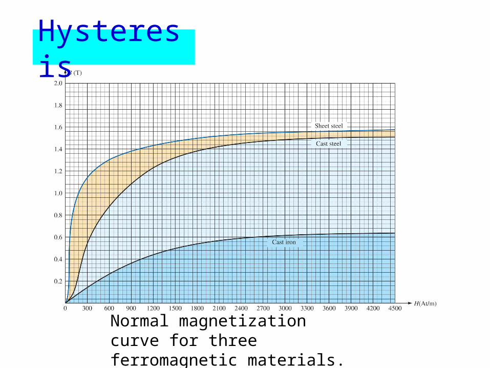
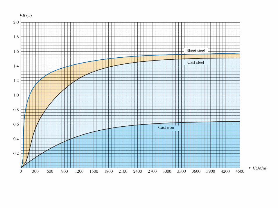
Normal magnetization curve for three ferromagnetic materials.
Hysteresis
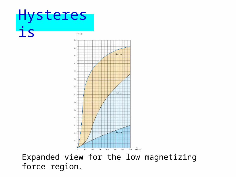
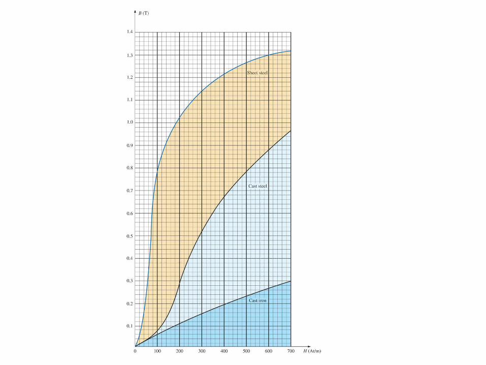
Expanded view for the low magnetizing force region.
Hysteresis
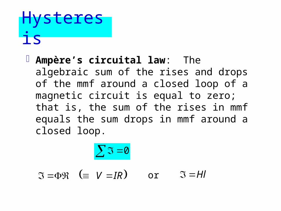
Ampère’s circuital law: The algebraic sum of the rises and drops of the mmf around a closed loop of a magnetic circuit is equal to zero; that is, the sum of the rises in mmf equals the sum drops in mmf around a closed loop.
0 IRV or Hl
Hysteresis
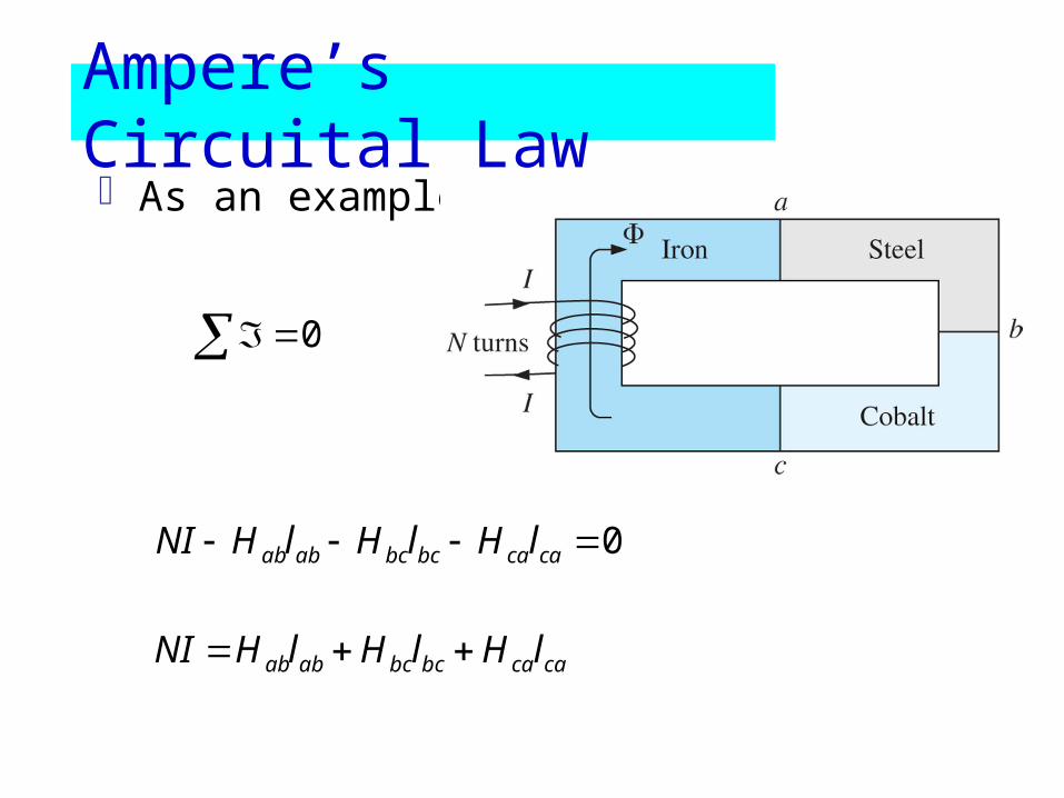
Ampere’s Circuital LawAs an example:
0 cacabcbcabab lHlHlHNI
0
cacabcbcabab lHlHlHNI
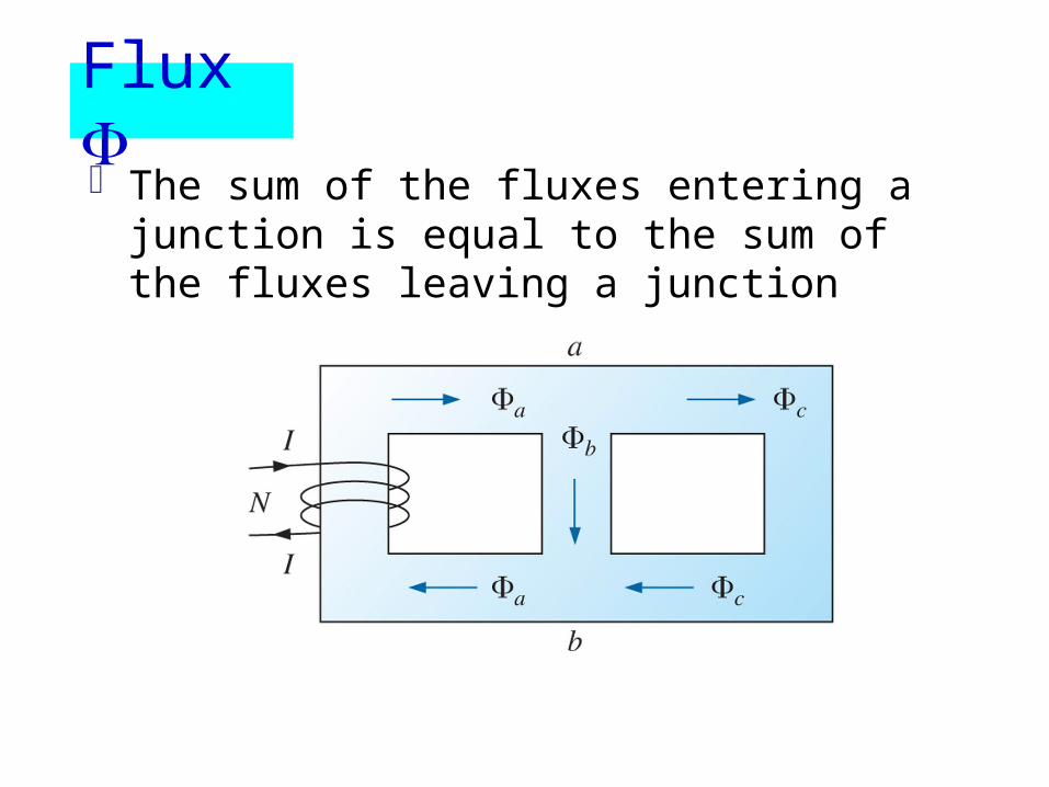
Flux The sum of the fluxes entering a junction is
equal to the sum of the fluxes leaving a junction
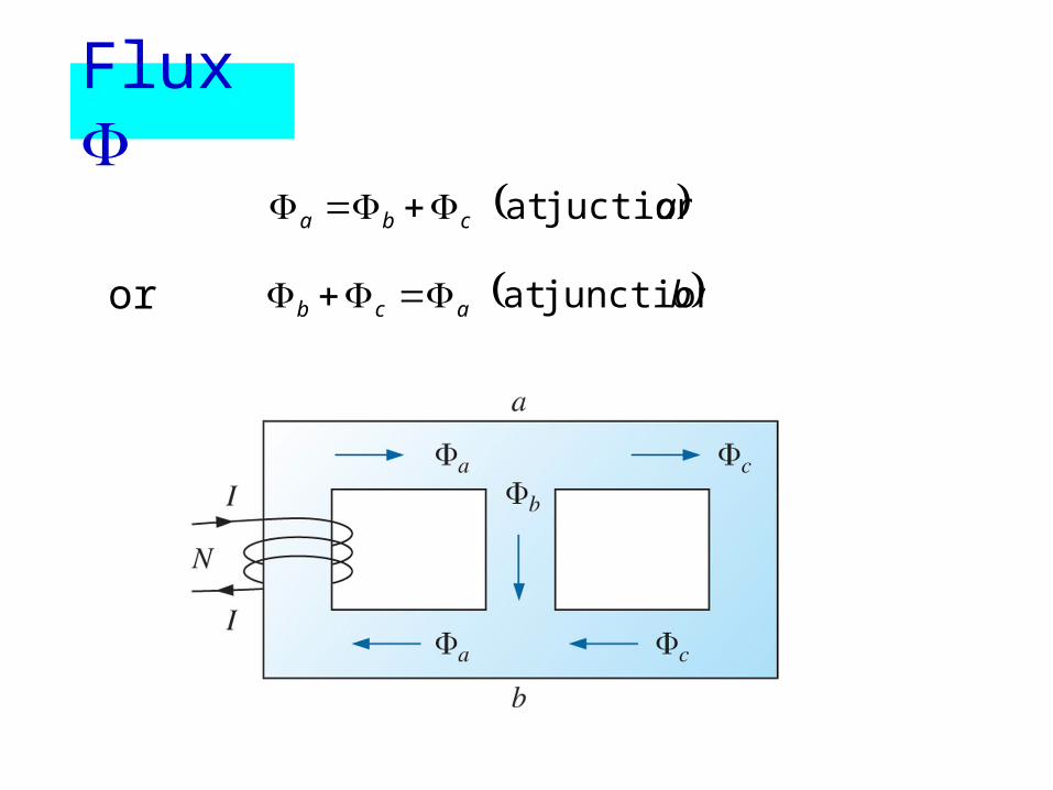
acba juction at
bacb junction at or
Flux
Series Magnetic Circuits : Determining NI
Two types of problems is given, and the impressed mmf NI
must be computed – design of motors, generators and transformers
NI is given, and the flux of the magnetic circuit must be found – design of magnetic amplifiers
Table method A table is prepared listing in the extreme
left-hand column the various sections of the magnetic circuit. The columns on the right are reserved for the quantities to be found for each section
Series Magnetic Circuits : Determining NI
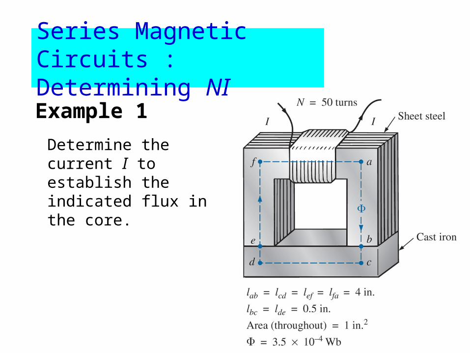
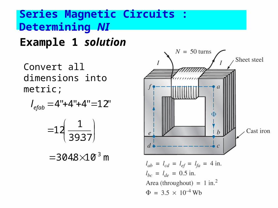
Example 1
Determine the current I to establish the indicated flux in the core.
Series Magnetic Circuits : Determining NI
Series Magnetic Circuits : Determining NI
Example 1 solution
"12"4"4"4 efabl
37.39
112
m 108.304 3
Convert all dimensions into metric;
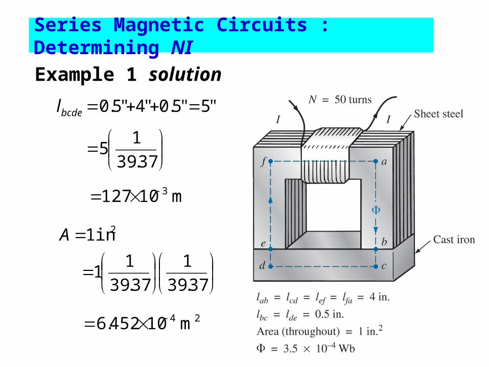
"5"5.0"4"5.0 bcdel
37.39
15
m 10127 3
2in 1A
37.39
1
37.39
11
24 m 10452.6
Series Magnetic Circuits : Determining NI
Example 1 solution
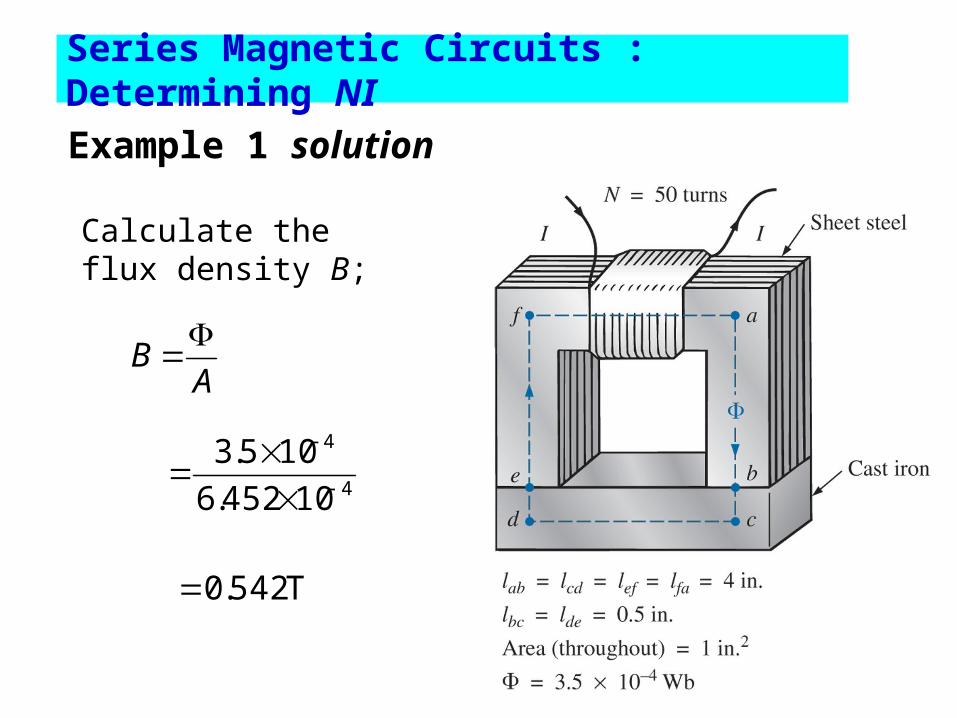
Calculate the flux density B;
AB
4
4
10452.6
105.3
T 542.0
Example 1 solution
Series Magnetic Circuits : Determining NI
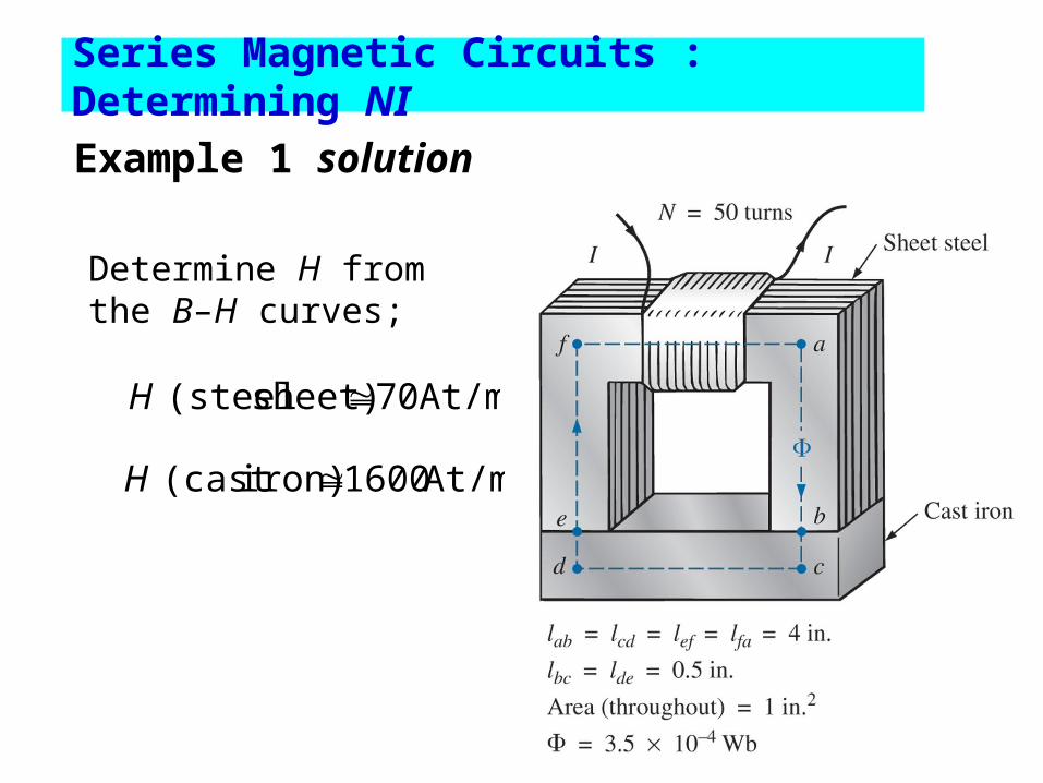
Determine H from the B–H curves;
At/m 70sheet) (steel H
At/m 1600iron)(cast H
Series Magnetic Circuits : Determining NI
Example 1 solution
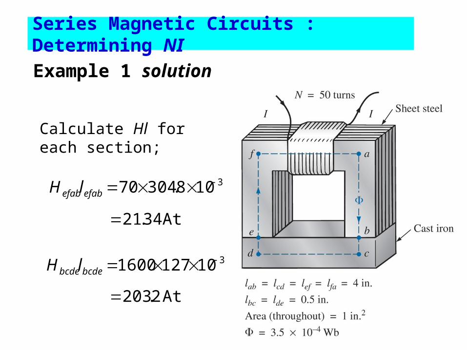
3108.30470 efabefablH
Calculate Hl for each section;
At 34.21
3101271600 bcdebcdelH
At 2.203
Series Magnetic Circuits : Determining NI
Example 1 solution

The magnetic circuit equivalent
The electric circuit analogy
At 54.2242.20334.21 bcdebcdeefabefab lHlHNI
A 4.4950
54.224I
Series Magnetic Circuits : Determining NI
Example 1 solution
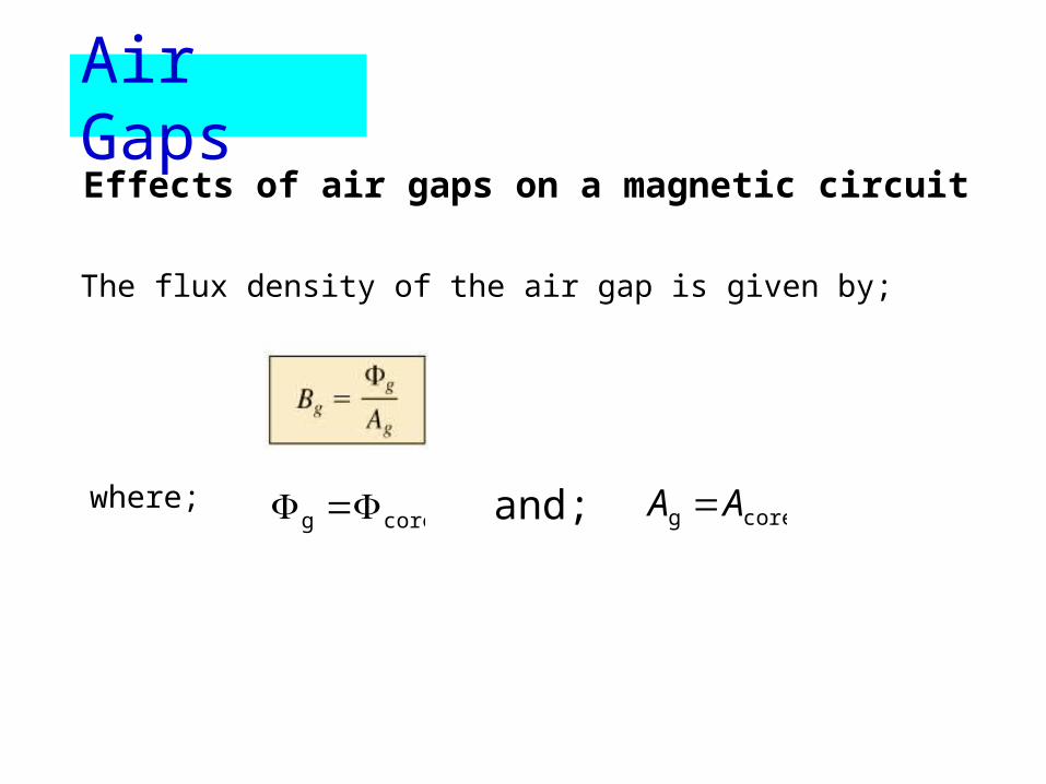
Air GapsEffects of air gaps on a magnetic circuit
coreg coreg AA
The flux density of the air gap is given by;
where; and;

Effects of air gaps on a magnetic circuit
Assuming the permeability of air is equal to that of free space, the magnetizing force of the air gap is determined by;
And the mmf drop across the air gap is equal to Hg Lg;
Air Gaps
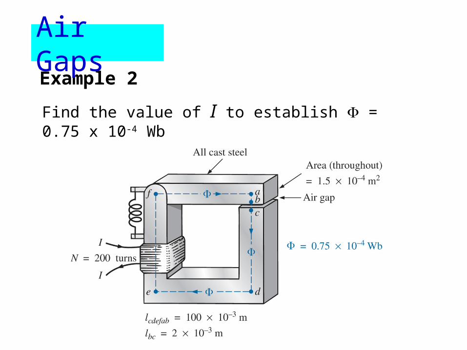
Example 2
Find the value of I to establish = 0.75 x 10⁻⁴ Wb
Air Gaps

AB
T 5.0105.1
1075.04
4
Calculate B;
Use B–H curves to determine H;
At/m 280steel)(cast H
Example 2
Air Gaps
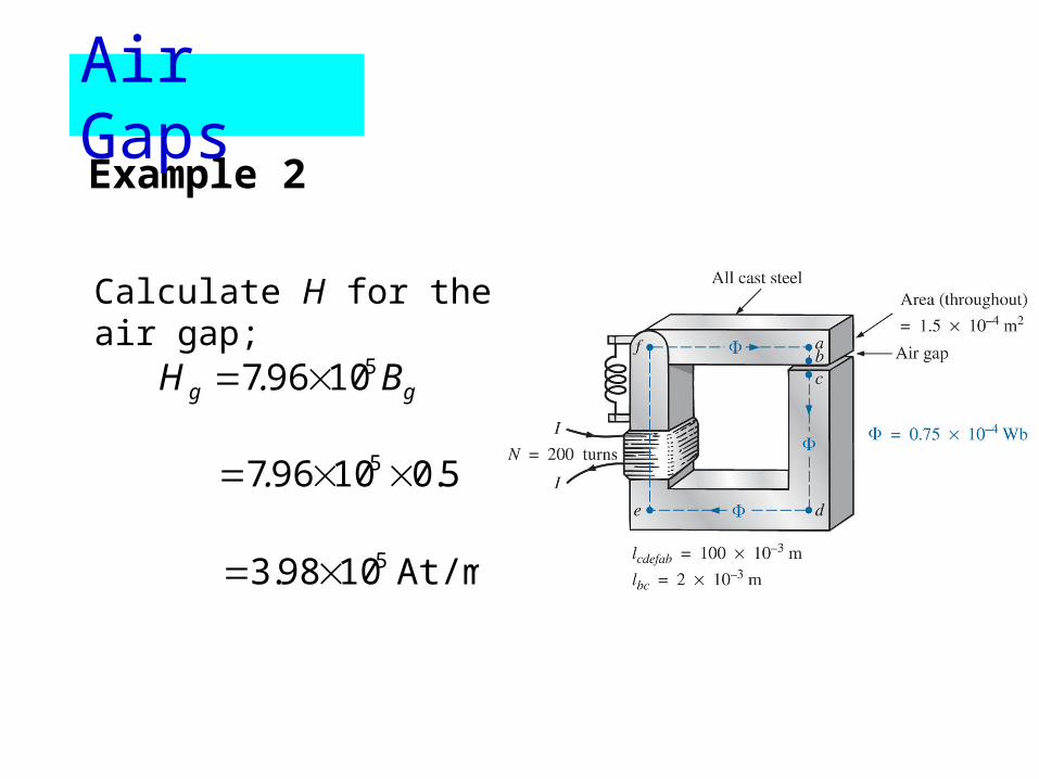
Calculate H for the air gap;
gg B.H 510967
5.010967 5 .
At/m 1098.3 5
Example 2
Air Gaps
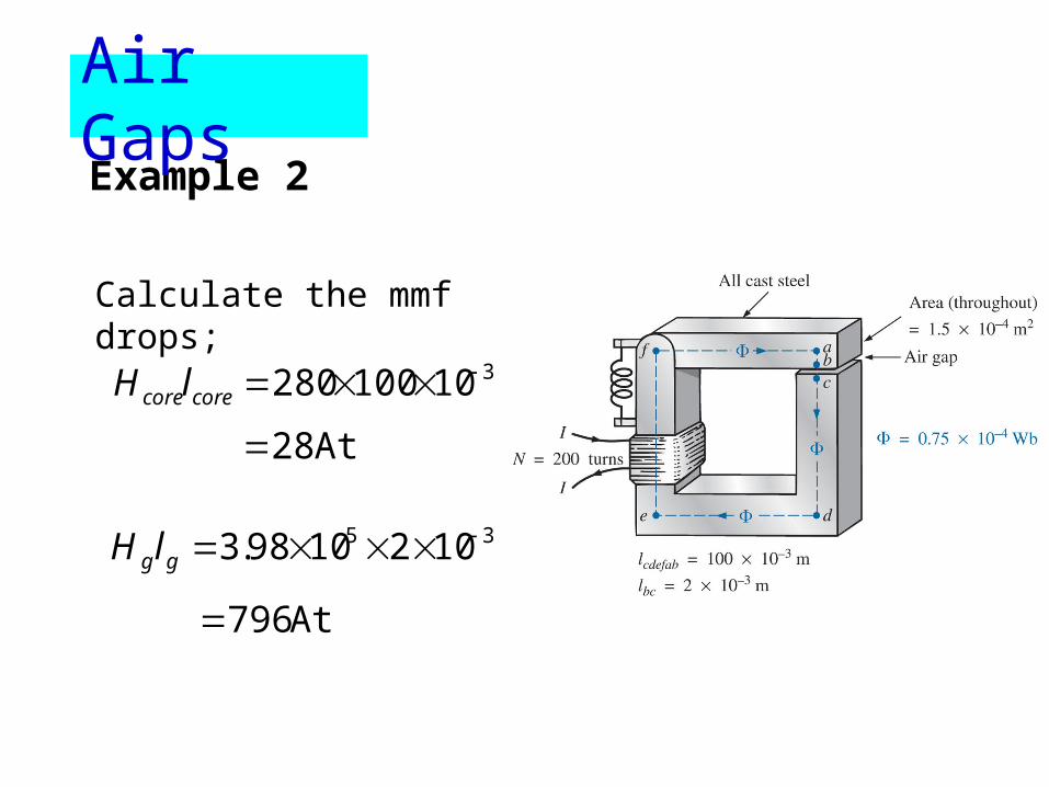
Calculate the mmf drops;
310100280 corecorelH
At 28
35 1021098.3 gglH
At 796
Example 2
Air Gaps
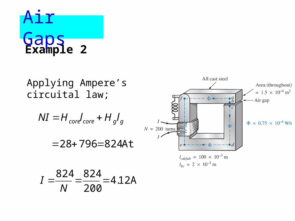
Applying Ampere’s circuital law;
ggcorecore lHlHNI
At 82479628
A 12.4200
824824
NI
Example 2
Air Gaps


![Chapter 12 Magnetism and Magnetic Circuits. 12.1The nature of a magnetic field [page 461] Magnetism refers to the force that acts betwewen magnets and](https://img.dokumen.tips/doc/110x75/56649de45503460f94adbba4/chapter-12-magnetism-and-magnetic-circuits-121the-nature-of-a-magnetic-field.jpg)


![1 L 27 Electricity and Magnetism [4] simple electrical circuits – direct current DC simple electrical circuits – direct current DC Alternating current](https://img.dokumen.tips/doc/110x75/56649dbc5503460f94aad840/1-l-27-electricity-and-magnetism-4-simple-electrical-circuits-direct.jpg)