Embed Size (px)
Citation preview
Chapter 18
OSPF Configuration Guidelines
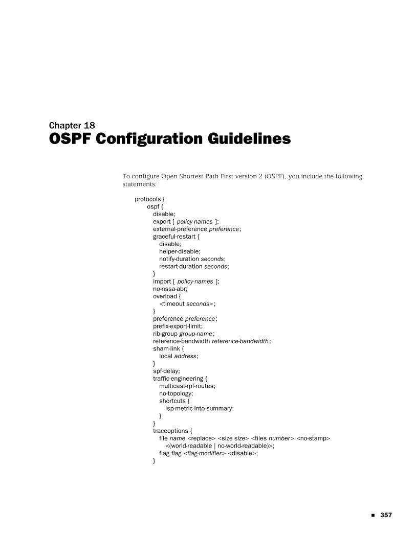
To configure Open Shortest Path First version 2 (OSPF), you include the followingstatements:
protocols {ospf {
disable;export [ policy-names ];external-preference preference;graceful-restart {
disable;helper-disable;notify-duration seconds;restart-duration seconds;
}import [ policy-names ];no-nssa-abr;overload {
<timeout seconds>;}preference preference;prefix-export-limit;rib-group group-name;reference-bandwidth reference-bandwidth;sham-link {
local address;}spf-delay;traffic-engineering {
multicast-rpf-routes;no-topology;shortcuts {
lsp-metric-into-summary;}
}traceoptions {
file name <replace> <size size> <files number> <no-stamp><(world-readable | no-world-readable)>;
flag flag <flag-modifier> <disable>;}
� 357
JUNOS 8.2 Routing Protocols Configuration Guide
358 �
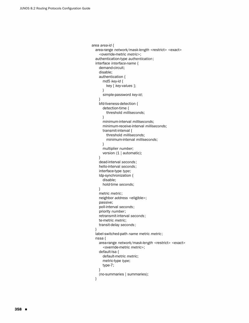
area area-id {area-range network/mask-length <restrict> <exact>
<override-metric metric>;authentication-type authentication;interface interface-name {
demand-circuit;disable;authentication {
md5 key-id {key [ key-values ];
}simple-password key-id;
}bfd-liveness-detection {
detection-time {threshold milliseconds;
}minimum-interval milliseconds;minimum-receive-interval milliseconds;transmit-interval {
threshold milliseconds;minimum-interval milliseconds;
}multiplier number;version (1 | automatic);
}dead-interval seconds;hello-interval seconds;interface-type type;ldp-synchronization {
disable;hold-time seconds;
}metric metric;neighbor address <eligible>;passive;poll-interval seconds;priority number;retransmit-interval seconds;te-metric metric;transit-delay seconds;
}label-switched-path name metric metric;nssa {
area-range network/mask-length <restrict> <exact><override-metric metric>;
default-lsa {default-metric metric;metric-type type;type-7;
}(no-summaries | summaries);
}
Chapter 18: OSPF Configuration Guidelines
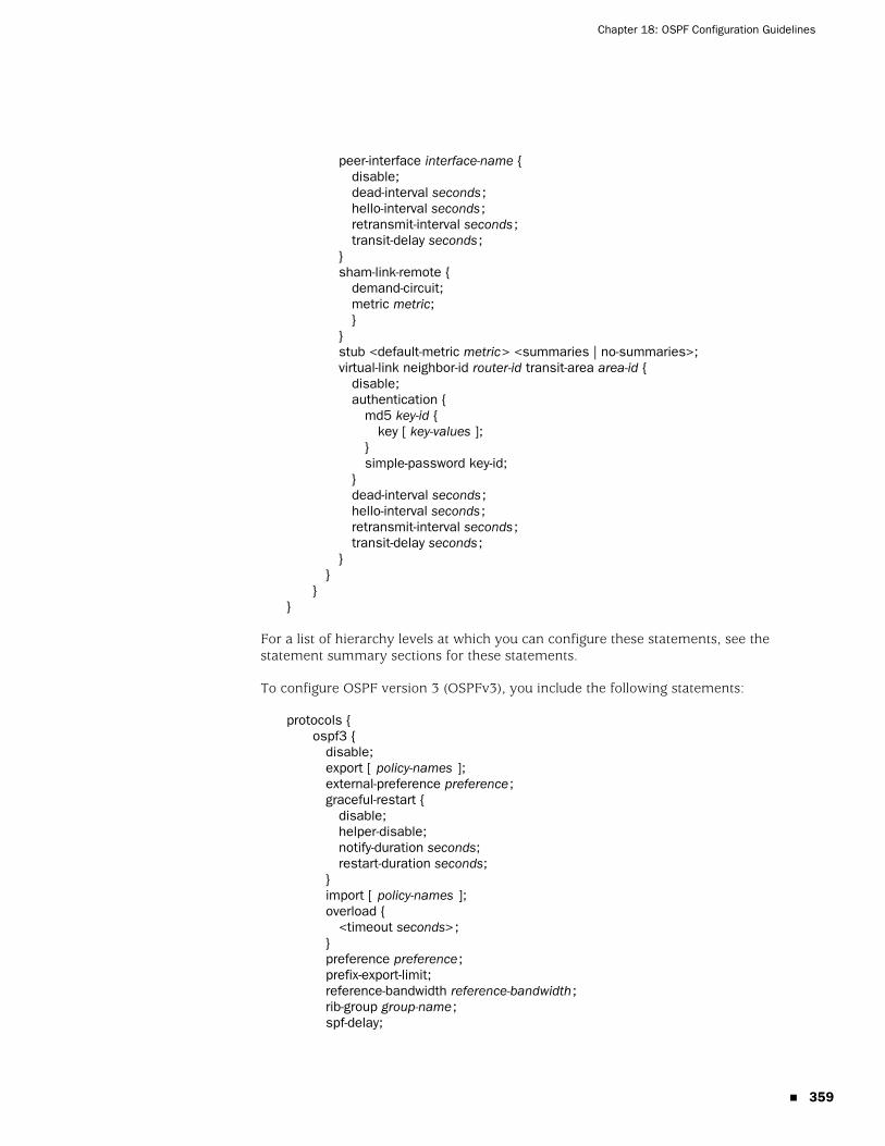
peer-interface interface-name {disable;dead-interval seconds;hello-interval seconds;retransmit-interval seconds;transit-delay seconds;
}sham-link-remote {
demand-circuit;metric metric;}
}stub <default-metric metric> <summaries | no-summaries>;virtual-link neighbor-id router-id transit-area area-id {
disable;authentication {
md5 key-id {key [ key-values ];
}simple-password key-id;
}dead-interval seconds;hello-interval seconds;retransmit-interval seconds;transit-delay seconds;
}}
}}
For a list of hierarchy levels at which you can configure these statements, see thestatement summary sections for these statements.
To configure OSPF version 3 (OSPFv3), you include the following statements:
protocols {ospf3 {
disable;export [ policy-names ];external-preference preference;graceful-restart {
disable;helper-disable;notify-duration seconds;restart-duration seconds;
}import [ policy-names ];overload {
<timeout seconds>;}preference preference;prefix-export-limit;reference-bandwidth reference-bandwidth;rib-group group-name;spf-delay;
� 359
JUNOS 8.2 Routing Protocols Configuration Guide
360 �
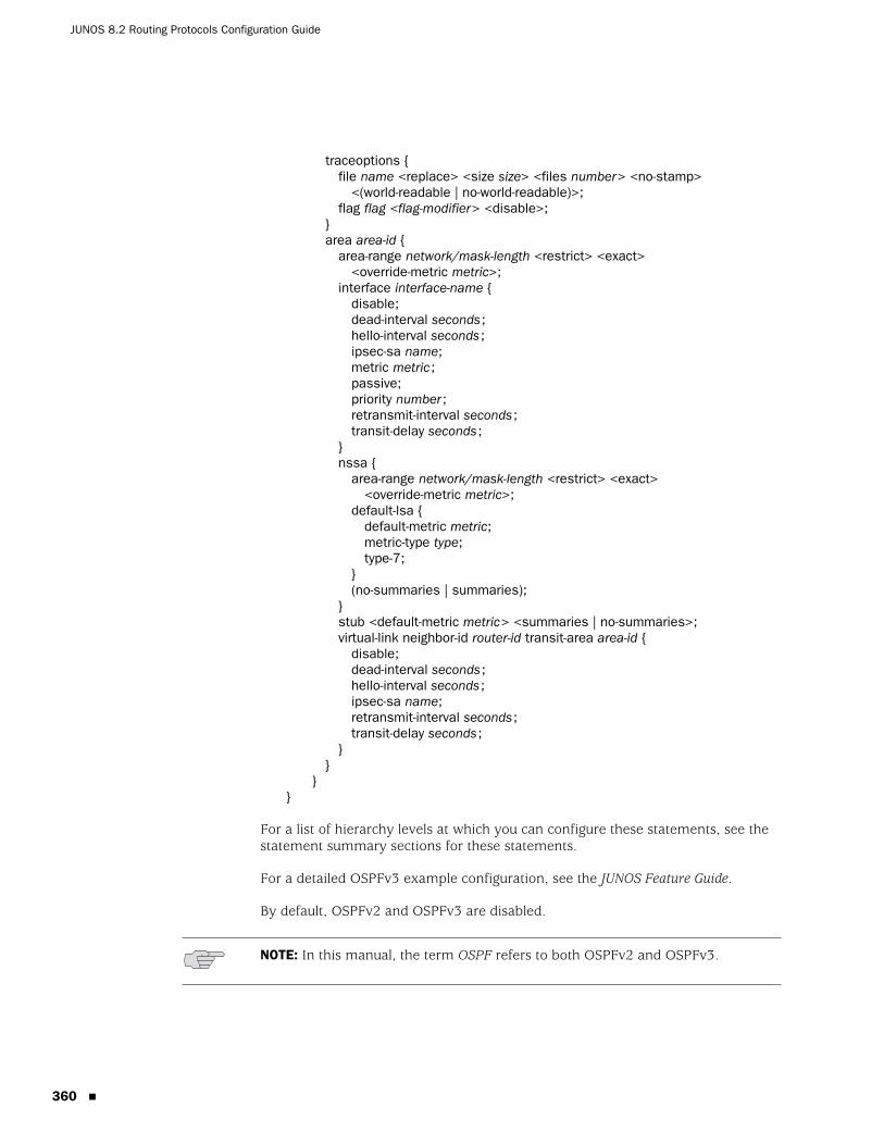
traceoptions {file name <replace> <size size> <files number> <no-stamp>
<(world-readable | no-world-readable)>;flag flag <flag-modifier> <disable>;
}area area-id {
area-range network/mask-length <restrict> <exact><override-metric metric>;
interface interface-name {disable;dead-interval seconds;hello-interval seconds;ipsec-sa name;metric metric;passive;priority number;retransmit-interval seconds;transit-delay seconds;
}nssa {
area-range network/mask-length <restrict> <exact><override-metric metric>;
default-lsa {default-metric metric;metric-type type;type-7;
}(no-summaries | summaries);
}stub <default-metric metric> <summaries | no-summaries>;virtual-link neighbor-id router-id transit-area area-id {
disable;dead-interval seconds;hello-interval seconds;ipsec-sa name;retransmit-interval seconds;transit-delay seconds;
}}
}}
For a list of hierarchy levels at which you can configure these statements, see thestatement summary sections for these statements.
For a detailed OSPFv3 example configuration, see the JUNOS Feature Guide.
By default, OSPFv2 and OSPFv3 are disabled.
NOTE: In this manual, the term OSPF refers to both OSPFv2 and OSPFv3.
Chapter 18: OSPF Configuration Guidelines
This chapter describes the following tasks for configuring OSPF:
� Minimum OSPF Configuration on page 362
� Configuring the Backbone Area and Other Areas on page 362
� Disabling NSSA Support on an ASBR ABR on page 366
� Configuring OSPF on Router Interfaces on page 366
� Configuring Authentication for OSPF on page 369
� Configuring Authentication for OSPFv3 on page 372
� Configuring a Prefix Export Limit on page 373
� Configuring the Priority for Becoming the Designated Router on page 373
� Configuring Route Summarization on page 374
� Modifying the Interface Metric on page 374
� Configuring Route Preferences on page 375
� Configuring OSPF Timers on page 376
� Configuring the BFD Protocol on page 378
� Configuring Label Distribution Protocol Synchronization with the IGP onpage 379
� Configuring Graceful Restart on page 380
� Configuring the SPF Delay on page 380
� Advertising Interface Addresses Without Running OSPF on page 381
� Advertising Label-Switched Paths into OSPF on page 381
� Configuring the Router to Appear Overloaded on page 382
� Enabling OSPF Traffic Engineering Support on page 383
� Modifying the Traffic Engineering Metric on page 384
� Configuring OSPF Routing Policy on page 385
� Configuring OSPF Routing Table Groups on page 386
� Configuring a Sham Link on page 386
� Configuring a Peer Interface on page 387
� Tracing OSPF Protocol Traffic on page 387
� 361
JUNOS 8.2 Routing Protocols Configuration Guide
362 �
Minimum OSPF Configuration
You must create a backbone area if your network consists of multiple areas. An areaborder router (ABR) must have at least one interface in the backbone area, or itmust have a virtual link to a router in the backbone area. To do this, include at leastthe following statements. All other OSPF configuration statements are optional.
protocols {(ospf | ospf3 ) {
area 0 {interface interface-name;
}}
}
For a list of hierarchy levels at which you can configure these statements, see thestatement summary sections for these statements.
Configuring the Backbone Area and Other Areas
You can group the routers in a single autonomous system (AS) into areas to reducethe amount of link-state advertisement (LSA) traffic on the network and to reducethe size of the topological databases that OSPF routers must maintain. If you dothis, the AS must contain a single backbone area and optionally can contain anynumber of nonbackbone areas. The routers that make up the backbone must bephysically contiguous. If they are not, you must configure virtual links to create theappearance of connectivity. You also can configure stub areas, which are areasthrough which AS external advertisements are not flooded, and not-so-stubby areas(NSSAs), which allow external routes to be flooded within an area.
The JUNOS software supports active backbone detection. Active backbonedetection is implemented to verify that area border routers are connected to thebackbone. If the connection to the backbone area is lost, then the router’s defaultmetric is not advertised, effectively rerouting traffic through another area borderrouter with a valid connection to the backbone.
Active backbone detection enables transit through an area border router with noactive backbone connection. An area border router advertises to other routers thatit is an area border router even if the connection to the backbone is down, so thatthe neighbors can consider it for inter-area routes.
NOTE: When you configure OSPFv2 on an interface, you must also include thefamily inet statement at the [edit interfaces interface-name unit logical-unit-number]hierarchy level. When you configure OSPFv3 on an interface, you must alsoinclude the family inet6 statement at the [edit interfaces interface-name unitlogical-unit-number] hierarchy level. For more information about the family inetstatement, see the JUNOS Network Interfaces Configuration Guide.
NOTE: OSPFv3 does not support routing instances.
Minimum OSPF Configuration
Chapter 18: OSPF Configuration Guidelines
To configure areas, you can perform the following tasks:
� Configuring the Backbone Area on page 363
� Configuring a Nonbackbone Area on page 363
� Configuring a Stub Area on page 363
� Configuring a Not-So-Stubby Area on page 364
� Configuring an OSPF Virtual Link on page 365
� Example: Configuring an OSPF Virtual Link on page 366
Configuring the Backbone AreaYou must create a backbone area if your network consists of multiple areas. AnABR must have at least one interface in the backbone area, or it must have a virtuallink to a router in the backbone area. The backbone comprises all area borderrouters and all routers that are not included in any other area. You configure allthese routers by including the following area statement:
(ospf | ospf3) {area 0.0.0.0;
}
For a list of hierarchy levels at which you can configure this statement, see thestatement summary section for this statement.
Configuring a Nonbackbone AreaEach OSPF area consists of routers configured with the same area number. Toconfigure a router to be in an area, include the area statement. The area numbercan be any number except 0.0.0.0, which is reserved for the backbone area.
(ospf | ospf3) {area area-id;
}
For a list of hierarchy levels at which you can configure this statement, see thestatement summary section for this statement.
Configuring a Stub AreaStub areas are areas into which OSPF does not flood AS external advertisements.You might want to configure stub areas when much of the topological databaseconsists of AS external advertisements and you want to minimize the size of thetopological databases on an area’s routers.
You cannot configure an area as being both a stub area and an NSSA.
Configuring the Backbone Area and Other Areas � 363
JUNOS 8.2 Routing Protocols Configuration Guide
364 �
To configure a stub area, include the stub statement:
(ospf | ospf3) {area area-id {
stub <default-metric metric> <(no-summaries | summaries)>;}
}
For a list of hierarchy levels at which you can configure this statement, see thestatement summary section for this statement.
To inject a default route with a specified metric value into the area, include thedefault-metric option and a metric value. The default route matches any destinationthat is not explicitly reachable from within the area.
To have the stub areas not advertise summary routes into the stub area, include theno-summaries option. Only the default route is advertised, and only if you includethe default-metric option. The default route injected into the not-so-stubby area(NSSA) is a Type 3 LSA.
You must include the stub statement when configuring all routers that are in thestub area.
Configuring a Not-So-Stubby AreaAn OSPF stub area has no external routes, so you cannot redistribute from anotherprotocol into a stub area. An NSSA allows external routes to be flooded within thearea. These routes are then leaked into other areas. However, external routes fromother areas still do not enter the NSSA.
You cannot configure an area to be both a stub area and an NSSA.
To configure an NSSA, include the nssa statement:
(ospf | ospf3) {area area-id {
nssa {area-range network/mask-length <restrict> <exact>
<override-metric metric>;default-lsa {
default-metric metric;metric-type type;type-7;
}}(no-summaries | summaries);
}}
For a list of hierarchy levels at which you can configure this statement, see thestatement summary section for this statement.
By default, a default route is not advertised. To advertise a default route with thespecified metric within the area, include the default-metric statement. You canconfigure this option only on area border routers.
Configuring the Backbone Area and Other Areas
Chapter 18: OSPF Configuration Guidelines
To prevent an ABR from advertising summary routes into an NSSA, include theno-summaries statement. If you include the default-metric option in addition to theno-summaries statement, only the default route is advertised. The default route is aType 3 LSA injected into the NSSA. To flood summary LSAs into the NSSA area,include the summaries statement. When summaries is configured (which is thedefault if the no-summaries statement is not specified), a Type 7 LSA is sent. Todefine the type of metric, include the metric-type statement.
To aggregate external routes learned within the area when a route is advertised toother areas, include one or more area-range statements. If you also include therestrict option, the aggregate is not advertised, effectively creating a route filter. Allexternal routes learned within the area that do not fall into the range of one of theprefixes are advertised individually to other areas. To restrict an exact area range,include the exact option. For an example, you can suppress the exact 0/0 prefixfrom being advertised from a NSSA area into the backbone area by including boththe exact and restrict options. To override the metric for the IP address range andconfigure a specific metric value, include the override-metric option.
Configuring an OSPF Virtual LinkIf any router on the backbone is not physically connected to the backbone itself,you must establish a virtual connection between that router and the backbone. Youcan establish a virtual connection between area border routers by configuring aOSPF virtual link.
To configure an OSPF virtual link, include the virtual-link statement whenconfiguring the backbone area (area 0):
virtual-link neighbor-id router-id transit-area area-id;
To configure an OSPFv3 virtual link, include the virtual-link statement whenconfiguring the backbone area (area 0):
virtual-link neighbor-id router-id transit-area area-id;
For a list of hierarchy levels at which you can configure this statement, see thestatement summary section for this statement.
Specify the router ID (as an IPv4 address) of the router at the other end of thevirtual link. This router must be an area border router that is physically connectedto the backbone. Also, specify the number of the area through which the virtual linktransits.
For the virtual connection to work, you also must configure a link to the backbonearea on the remote area border router (the router at the other end of the LSP).
Configuring the Backbone Area and Other Areas � 365
JUNOS 8.2 Routing Protocols Configuration Guide
366 �
Example: Configuring an OSPF Virtual LinkConfigure an OSPF virtual link on the local router. This router must be an areaborder router that is physically connected to the backbone.
[edit protocols ospf]area 0.0.0.0 {
virtual-link neighbor-id 192.168.0.3 transit-area 1.1.1.1;interface t3-1/0/0 {
hello-interval 1;dead-interval 3;
}}
You must also configure an OSPF virtual link on the remote area border router:
[edit protocols ospf]area 0.0.0.0 {
virtual-link neighbor-id 192.168.0.5 transit-area 1.1.1.1;}
Disabling NSSA Support on an ASBR ABR
When an autonomous-system border router (ASBR) is also an ABR with an NSSAarea attached to it, a Type 7 LSA is exported into the NSSA area by default. If theABR is attached to multiple NSSA areas, a separate Type 7 LSA is exported intoeach NSSA area by default.
To disable exporting Type 7 LSAs into NSSAs, include the no-nssa-abr statement:
no-nssa-abr;
For a list of hierarchy levels at which you can configure this statement, see thestatement summary section for this statement.
Configuring OSPF on Router Interfaces
To enable OSPF on the router, you must configure OSPF on at least one of therouter’s interfaces. How you configure an interface depends on whether theinterface is connected to a broadcast or point-to-point network, apoint-to-multipoint network, or a nonbroadcast, multiaccess network.
NOTE: Type 7 LSAs are not exported into an NSSA if there is only one NSSA andbackbone area connected to the ABR.
NOTE: When you configure OSPFv2 on an interface, you must also include thefamily inet statement at the [edit interfaces interface-name unit logical-unit-number]hierarchy level. When you configure OSPFv3 on an interface, you must alsoinclude the family inet6 statement at the [edit interfaces interface-name unitlogical-unit-number] hierarchy level. For more information about the family inetstatement, see the JUNOS Network Interfaces Configuration Guide.
Disabling NSSA Support on an ASBR ABR
Chapter 18: OSPF Configuration Guidelines
To configure OSPF on an interface, you can perform the following tasks:
� Configuring an Interface on a Broadcast or Point-to-Point Network on page 367
� Configuring an Interface on a Point-to-Multipoint Network on page 367
� Configuring an Interface on a Nonbroadcast, Multiaccess Network on page 368
� Configuring an OSPF Demand Circuit Interface on page 369
Configuring an Interface on a Broadcast or Point-to-Point NetworkIf the interface on which you are configuring OSPF supports broadcast mode (suchas a LAN), or if the interface supports point-to-point mode (such as a PPP interfaceor a point-to-point logical interface on Frame Relay), include the following form ofthe interface statement:
ospf | ospf3) {area area-id {
interface interface-name;}
}
For a list of hierarchy levels at which you can configure this statement, see thestatement summary section for this statement.
Specify the interface by IP address or interface name for OSPFv2, or only theinterface name for OSPFv3. For more information about interface names, see theJUNOS Network Interfaces Configuration Guide.
Configuring an Interface on a Point-to-Multipoint NetworkWhen you configure OSPFv2 on a nonbroadcast multiaccess (NBMA) network, suchas a multipoint ATM or Frame Relay, OSPFv2 operates by default inpoint-to-multipoint mode. In this mode, OSPFv2 treats the network as a set ofpoint-to-point links. Because there is no autodiscovery mechanism, each neighbormust be configured.
To configure OSPFv2 in point-to-multipoint mode, include the following statement:
interface interface-name {neighbor address;
}
For a list of hierarchy levels at which you can configure this statement, see thestatement summary section for this statement.
Specify the interface by IP address or interface name. For more information aboutinterface names, see the JUNOS Network Interfaces Configuration Guide.
To configure multiple neighbors, include a neighbor statement for each neighbor.
Configuring OSPF on Router Interfaces � 367
JUNOS 8.2 Routing Protocols Configuration Guide
368 �
Configuring an Interface on a Nonbroadcast, Multiaccess NetworkWhen configuring OSPFv2 on an NBMA network, you can use nonbroadcast moderather than point-to-multipoint mode. Using this mode offers no advantages overpoint-to-multipoint mode, but it has more disadvantages than point-to-multipointmode. Nevertheless, you might occasionally find it necessary to configurenonbroadcast mode to interoperate with other equipment.
Nonbroadcast mode treats the NBMA network as a partially connected LAN,electing designated and backup designated routers. All routers must have a directconnection to both the designated and backup designated routers, or unpredictableresults occur.
To configure nonbroadcast mode, include the following statements:
interface interface-name {interface-type nbma;neighbor address <eligible>;poll-interval seconds;
}
For a list of hierarchy levels at which you can configure these statements, see thestatement summary sections for these statements.
Specify the interface by IP address or interface name. For more information aboutinterface names, see the JUNOS Network Interfaces Configuration Guide.
To configure multiple neighbors, include a neighbor statement for each neighbor.
OSPF routers normally discover their neighbors dynamically by listening to thebroadcast or multicast hello packets on the network. Because an NBMA networkdoes not support broadcast (or multicast), the router cannot discover its neighborsdynamically, so you must configure all the neighbors statically. Do this by includingthe neighbor statement and specifying the IP address of each neighboring router inthe address option. To configure multiple neighbors, include multiple neighborstatements. If the neighbor is allowed to become the designated router, include theeligible keyword.
By default, the router sends hello packets out the interface every 120 secondsbefore it establishes adjacency with a neighbor. To modify this interval, include thepoll-interval statement.
NOTE: For nonbroadcast interfaces, specify the IP address of the nonbroadcastinterface as the interface-name.
Configuring OSPF on Router Interfaces
Chapter 18: OSPF Configuration Guidelines
Configuring an OSPF Demand Circuit InterfaceA demand circuit is a connection on which you can limit traffic based on useragreements. The demand circuit can limit bandwidth or access time based uponagreements between the provider and user.
Demand circuits can be used to implement Integrated Services Digital Network(ISDN). For this application, demand circuits are configured on point-to-point andpoint-to-multipoint interfaces. For more information on ISDN, see the J-seriesServices Router Advanced WAN Access Configuration Guide.
Demand circuits can be configured on an OSPF interface. When the interfacebecomes a demand circuit, all hello packets and link-state advertisements aresuppressed as soon as OSPF synchronization is achieved. Hello packets andlink-state advertisements are sent and received on a demand-circuit interface onlywhen there is a change in the network topology. This reduces the amount of trafficthrough the OSPF interface.
To configure an OSPF interface as a demand circuit, include the demand-circuitstatement:
(ospf | ospf3) {area area-id {
demand-circuit;}
}
For a list of hierarchy levels at which you can configure this statement, see thestatement summary section for this statement.
A demand-circuit interface automatically negotiates demand-circuit connectionwith its OSPF neighbor. If the neighbor does not support demand circuits, then nodemand circuit connection is established.
Configuring Authentication for OSPF
All OSPFv2 protocol exchanges can be authenticated to guarantee that only trustedrouters participate in the AS’s routing. By default, OSPFv2 authentication isdisabled. You can configure one of the following authentication methods. Each areamust use the same method.
Simple authentication uses a text password that is included in the transmittedpacket. The receiving router uses an authentication key (password) to verify thepacket.
The MD5 algorithm creates an encoded checksum that is included in thetransmitted packet. The receiving router uses an authentication key (password) toverify the packet.
For MD5 authentication to work, both the receiving and transmitting routers musthave the same MD5 key. Define an MD5 key for each interface. If MD5 is enabledon an interface, that interface accepts routing updates only if MD5 authenticationsucceeds; otherwise, updates are rejected. The key ID can be set to any valuebetween 0 and 255, with a default value of 0. The router only accepts OSPFv2packets sent using the same key ID that is defined for that interface.
Configuring Authentication for OSPF � 369
JUNOS 8.2 Routing Protocols Configuration Guide
370 �
To enable authentication and specify an authentication method, include theauthentication-type statement:
authentication-type authentication;
The authentication type can be none, simple, or md5. The same authentication typeis used on all interfaces under an OSPF area.
If you include the authentication-type statement to select an authentication method,you can configure a key (password) on each interface by including theauthentication statement:
authentication {md5 key-id {
key [ key-values ] {start-time time;
}}simple-password key-id;
}
For a list of hierarchy levels at which you can configure these statements, see thestatement summary sections for these statements.
The simple key (password) can be from 1 through 8 characters long. Each MD5 keyis identified by a key identifier. The MD5 key value can be from 1 through 16characters long. Characters can include ASCII strings. If you include spaces, encloseall characters in quotation marks (" ").
A simple password and MD5 key are mutually exclusive.
You can configure only one simple password. However, you can configure multipleMD5 keys.
As part of your security measures, you can change MD5 keys. You can do this byconfiguring multiple MD5 keys, each with a unique key ID, and setting the date andtime to switch to the new key. Each unique MD5 key has a unique ID. The ID is usedby the receiver of the OSPF packet to determine which key to use forauthentication. The key identifier, which is required for MD5 authentication,specifies the identifier associated with the MD5 key.
The start time specifies when to start using the MD5 key. This is optional. Thestart-time option enables you to configure a smooth transition mechanism formultiple keys. The start time is relevant for transmission but not for receiving OSPFpackets.
See the following sections:
� Example: Configuring a Transition of MD5 Keys on page 371
� Example: Configuring MD5 Authentication on page 372
Configuring Authentication for OSPF
Chapter 18: OSPF Configuration Guidelines
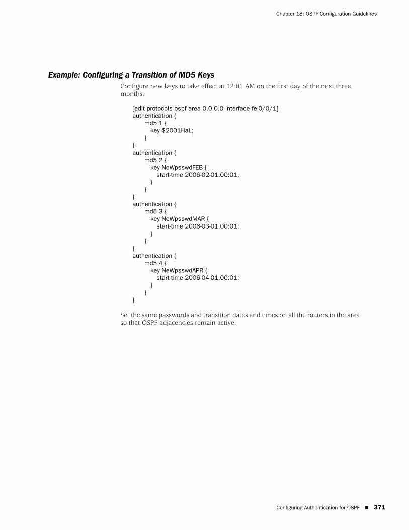
Example: Configuring a Transition of MD5 KeysConfigure new keys to take effect at 12:01 AM on the first day of the next threemonths:
[edit protocols ospf area 0.0.0.0 interface fe-0/0/1]authentication {
md5 1 {key $2001HaL;
}}authentication {
md5 2 {key NeWpsswdFEB {
start-time 2006-02-01.00:01;}
}}authentication {
md5 3 {key NeWpsswdMAR {
start-time 2006-03-01.00:01;}
}}authentication {
md5 4 {key NeWpsswdAPR {
start-time 2006-04-01.00:01;}
}}
Set the same passwords and transition dates and times on all the routers in the areaso that OSPF adjacencies remain active.
Configuring Authentication for OSPF � 371
JUNOS 8.2 Routing Protocols Configuration Guide
372 �
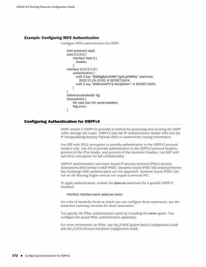
Example: Configuring MD5 AuthenticationConfigure MD5 authentication for OSPF:
[edit protocols ospf]area 0.0.0.0 {
interface fxp0.0 {disable;
}interface t1-0/2/1.0 {
authentication {md5 3 key "$9$6gBqCtOW87YgJEcyKW8Vb" start-time
2002-11-19.10:00; # SECRET-DATA;md5 2 key "$9$DJHkP5T3/A0Uj6A0Irl"; # SECRET-DATA;
}}reference-bandwidth 4g;traceoptions {
file ospf size 5m world-readable;flag error;
}
Configuring Authentication for OSPFv3
OSPF version 3 (OSPFv3) provides a method for protecting and securing the OSPFtraffic through the router. OSPFv3 uses the IP Authentication Header (AH) and theIP Encapsulating Security Payload (ESP) to authenticate routing information.
Use ESP with NULL encryption to provide authentication to the OSPFv3 protocolheaders only. Use AH to provide authentication to the OSPFv3 protocol headers,portions of the IPv6 header, and portions of the extension headers. Use ESP withnon-NULL encryption for full confidentiality.
OSPFv3 authentication uses static keyed IP security protocol (IPSec) securityassociations (SAs) similar to BGP IPSEC. Dynamic keyed IPSEC SAs utilizing InternetKey Exchange (IKE) authentication are not supported. Dynamic keyed IPSEC SAsrun on the Routing Engine and do not require a services PIC.
To apply authentication, include the ipsec-sa statement for a specific OSPFv3interface:
interface interface-name ipsec-sa name;
For a list of hierarchy levels at which you can configure these statements, see thestatement summary sections for these statements.
You specify the IPSec authentication name by including the name option. Youconfigure the actual IPSec authentication separately.
For more information on IPSec, see the JUNOS System Basics Configuration Guideand the JUNOS Services Interfaces Configuration Guide.
Configuring Authentication for OSPFv3
Chapter 18: OSPF Configuration Guidelines
Configuring a Prefix Export Limit
By default, there is no limit to the number of prefixes that can be exported intoOSPF. To limit the number of prefixes, include the prefix-export-limit statement:
(ospf | ospf3) {level level-number {
prefix-export-limit number;}
}
For a list of hierarchy levels at which you can configure this statement, see thestatement summary section for this statement.
The number can be a value from 0 through 4,294,967,295.
Configuring the Priority for Becoming the Designated Router
A router advertises its priority to become a designated router in its hello packets.On all multiaccess networks, the Hello protocol uses the advertised priorities toelect a designated router for the network. This router is responsible for sendingnetwork link advertisements, which describe all the routers attached to thenetwork. These advertisements are flooded throughout a single area.
At least one router on each logical IP network or subnet must be eligible to be thedesignated router for OSPFv2. At least one router on each logical link must beeligible to be the designated router for OSPFv3.
A router’s priority for becoming the designated router is indicated by an arbitrarynumber from 0 through 255, with a higher value indicating a greater likelihood ofbecoming the designated router. By default, routers have a priority value of 128. Avalue of 1 means that the router has the least chance of becoming a designatedrouter. A value of 0 marks the router as ineligible to become the designated router.
To modify the router’s priority value, include the priority statement:
(ospf | ospf3) {area area-id interface interface-name {
priority number;}
}
For a list of hierarchy levels at which you can configure this statement, see thestatement summary section for this statement.
Configuring a Prefix Export Limit � 373
JUNOS 8.2 Routing Protocols Configuration Guide
374 �
Configuring Route Summarization
Area border routers send summary link advertisements to describe the routes toother areas. To minimize the number of these advertisements that are flooded, youcan configure the router to coalesce, or summarize, a range of IP addresses andsend reachability information about these addresses in a single link-stateadvertisement.
To summarize a range of IP addresses, include the area-range statement. Tosummarize multiple ranges, include multiple area-range statement.
(ospf | ospf3) {area area-id {
area-range network/mask-length <restrict > <exact><override-metric metric>;
}}
For a list of hierarchy levels at which you can configure this statement, see thestatement summary section for this statement.
All routes that match the specified area range are filtered at the area boundary, andthe summary is advertised in their place. If you specify the restrict option, theroutes are filtered but no summary is advertised. If you specify the exact option,summarization of a route is advertised only when an exact match is made with theconfigured summary range. To override the metric for the IP address range andconfigure a specific metric value, include the override-metric option. If you specifythe override-metric option, the dynamically computed metric for the IP addressrange is overridden by the specified value.
Modifying the Interface Metric
All OSPF interfaces have a cost, which is a routing metric that is used in thelink-state calculation. Routes with lower total path metrics are preferred over thosewith higher path metrics.
When several equal-cost routes to a destination exist, traffic is distributed equallyamong them.
The cost of a route is described by a single dimensionless metric that is determinedusing the following formula:
cost = reference-bandwidth/bandwidth
reference-bandwidth is the reference bandwidth. Its default value is 100 Mbps (whichyou specify as 100,000,000), which gives a metric of 1 for any bandwidth that is100 Mbps or greater.
Configuring Route Summarization
Chapter 18: OSPF Configuration Guidelines
To modify the metric for routes advertised from an interface, include the metricstatement:
(ospf | ospf3) {area area-id interface interface-name {
metric metric;}
}
To modify the reference bandwidth, include the reference-bandwidth statement:
(ospf | ospf3) {reference-bandwidth reference-bandwidth;
}
For a list of hierarchy levels at which you can configure these statements, see thestatement summary sections for these statements.
For example, if you set the reference bandwidth to 1 Gbps (that is,reference-bandwidth is set to 1,000,000,000), a 100-Mbps interface has a defaultmetric of 10.
By default, the loopback interface (lo0) metric is 0. No bandwidth is associated withthe loopback interface.
Configuring Route Preferences
Route preferences are used to select which route is installed in the forwarding tablewhen several protocols calculate routes to the same destination. The route with thelowest preference value is selected. For more information about route preferences,see “Route Preferences” on page 6.
By default, internal OSPF routes have a preference value of 10, and external OSPFroutes have a value of 150. To change the preference values, include the preferencestatement (for internal routes) or the external-preference statement (for externalroutes):
(ospf | ospf3) {external-preference preference;preference preference;
}
For a list of hierarchy levels at which you can configure this statement, see thestatement summary section for this statement.
The preference can be a value from 0 through 255.
Configuring Route Preferences � 375
JUNOS 8.2 Routing Protocols Configuration Guide
376 �
Configuring OSPF Timers
OSPF routers constantly track the status of their neighbors, sending and receivinghello packets that indicate whether the neighbor still is functioning, and sendingand receiving link-state advertisement and acknowledgment packets. OSPF sendspackets and expects to receive packets at specified intervals.
You can perform the following tasks when modifying the OSPF timers:
� Modifying the Hello Interval on page 376
� Controlling the LSA Retransmission Interval on page 377
� Modifying the Router Dead Interval on page 377
� Specifying the Transit Delay on page 377
Modifying the Hello IntervalRouters send hello packets at a fixed interval on all interfaces, including virtuallinks, to establish and maintain neighbor relationships. This interval, which must bethe same on all routers on a shared network, is advertised in the hello interval fieldin the hello packet. By default, the router sends hello packets every 10 seconds.
To modify how often the router sends hello packets out of an interface, include thehello-interval statement:
hello-interval seconds;
For a list of hierarchy levels at which you can configure this statement, see thestatement summary section for this statement.
On nonbroadcast networks, the router sends hello packets every 120 seconds untilactive neighbors are detected by default. This interval is long enough to minimizethe bandwidth required on slow WAN links. To modify this interval, include thepoll-interval statement:
poll-interval seconds;
For a list of hierarchy levels at which you can configure this statement, see thestatement summary section for this statement.
Once the router detects an active neighbor, the hello packet interval changes fromthe time specified in the poll-interval statement to the time specified in thehello-interval statement.
NOTE: The poll-interval statement is valid for OSPFv2 only.
Configuring OSPF Timers
Chapter 18: OSPF Configuration Guidelines
Controlling the LSA Retransmission IntervalWhen a router sends link-state advertisements to its neighbors, the router expectsto receive an acknowledgment packet from the neighbor within a certain amount oftime. If the router does not receive an acknowledgment, it retransmits theadvertisement.
By default, the router waits 5 seconds for an acknowledgment beforeretransmitting the link-state advertisement. To modify this interval, include theretransmit-interval statement:
retransmit-interval seconds;
For a list of hierarchy levels at which you can configure this statement, see thestatement summary section for this statement.
Modifying the Router Dead IntervalIf a router does not receive a hello packet from a neighbor within a fixed amount oftime, the router modifies its topological database to indicate that the neighbor isnonoperational. The time that the router waits is called the router dead interval. Bydefault, this interval is 40 seconds (four times the default hello interval).
To modify the router dead interval, include the dead-interval statement. This intervalmust be the same for all routers on a shared network.
dead-interval seconds;
For a list of hierarchy levels at which you can configure this statement, see thestatement summary section for this statement.
Specifying the Transit DelayBefore a link-state update packet is propagated out of an interface, the router mustincrease the age of the packet. If you have a very slow link (for example, one withan average propagation delay of multiple seconds), the age of the packet must beincreased by a similar amount. Doing this ensures that you do not receive a packetback that is younger than the original copy.
The default transit delay is 1 second. You should never have to modify the defaultvalue. However, if you need to specify the approximate transit delay to use to ageupdate packets, include the transit-delay statement:
transit-delay seconds;
For a list of hierarchy levels at which you can configure this statement, see thestatement summary section for this statement.
NOTE: You must configure LSA retransmit intervals to be equal or greater than 3seconds to avoid triggering a retransmit trap because the JUNOS software delaysLSA acknowledgments by up to 2 seconds.
Configuring OSPF Timers � 377
JUNOS 8.2 Routing Protocols Configuration Guide
378 �
Configuring the BFD Protocol
The Bidirectional Forwarding Detection (BFD) protocol is a simple hello mechanismthat detects failures in a network. BFD works with a wide variety of networkenvironments and topologies. The BFD failure detection timers have shorter timelimits than the OSPF failure detection mechanisms, providing faster detection. Youcan adjust these timers to be more or less aggressive.
To enable failure detection, include the bfd-liveness-detection statement:
bfd-liveness-detection {detection-time {
threshold milliseconds;}minimum-interval milliseconds;minimum-receive-interval milliseconds;transmit-interval {
threshold milliseconds;minimum-interval milliseconds;
}multiplier number;version (1 | automatic);
}
To specify the threshold for the adaptation of the detection time, include thethreshold statement:
detection-time {threshold milliseconds;
}
To specify the minimum transmit and receive interval for failure detection, includethe minimum-interval statement:
minimum-interval milliseconds;
To specify only the minimum receive interval for failure detection, include theminimum-receive-interval statement:
minimum-receive-interval milliseconds;
To specify the threshold for detecting the adaptation of the transmit interval,include the threshold statement:
transmit-interval {threshold milliseconds;
}
NOTE: BFD is not supported for OSPFv3.
NOTE: Specifying an interval smaller than 300 ms can cause undesired BFDflapping.
Configuring the BFD Protocol
Chapter 18: OSPF Configuration Guidelines
The threshold value must be greater than the transmit interval.
To specify only the minimum transmit interval for failure detection, include theminimum-interval statement:
transmit-interval {minimum-interval milliseconds;
}
To specify the detection time multiplier for failure detection, include the multiplierstatement:
multiplier number;
To specify the BFD version used for detection, include the version statement:
version (1 | automatic);
For a list of hierarchy levels at which you can configure these statements, see thestatement summary sections for these statements.
Configuring Label Distribution Protocol Synchronization with the IGP
The Label Distribution Protocol (LDP) is a protocol for distributing labels innon-traffic-engineered applications. Labels are distributed along the best pathdetermined by the IGP. If synchronization between LDP and the IGP is notmaintained, the label-switch path (LSP) goes down. When LDP is not fullyoperational on a given link (a session is not established and labels are notexchanged), the IGP advertises the link with the maximum cost metric. The link isnot preferred but remains in the network topology.
LDP synchronization is supported only on active point-to-point interfaces and LANinterfaces configured as point-to-point under the IGP. LDP synchronization is notsupported during graceful restart.
To advertise the maximum cost metric until LDP is operational for synchronization,include the ldp-synchronization statement:
ldp-synchronization {disable;hold-time seconds;
}
To disable synchronization, include the disable statement. To configure the timeperiod to advertise the maximum cost metric for a link that is not fully operational,include the hold-time statement.
For a list of hierarchy levels at which you can configure this statement, see thestatement summary section for this statement.
NOTE: If you do not configure the hold-time option, the hold-time value willdefault to infinity.
Configuring Label Distribution Protocol Synchronization with the IGP � 379
JUNOS 8.2 Routing Protocols Configuration Guide
380 �
Configuring Graceful Restart
OSPF supports two types of graceful restart: planned and unplanned. During aplanned restart, the restarting router informs the neighbors before restarting. Theneighbors act as if the router is still within the network topology, and continueforwarding traffic to the restarting router. A grace period is set to specify the timeperiod for which the neighbors should consider the restarting router as part of thetopology. During an unplanned restart, the router restarts without warning.
Graceful restart is disabled by default. You can globally enable graceful restart for allrouting protocols at the [edit routing-options] hierarchy level.
To configure graceful restart parameters specifically for OSPF, include thegraceful-restart statement:
(ospf | ospf3) {graceful-restart {
disable;helper-disable;notify-duration seconds;restart-duration seconds;
}}
For a list of hierarchy levels at which you can configure this statement, see thestatement summary section for this statement.
To disable graceful restart, specify the disable statement. To configure a time periodfor complete reacquisition of OSPF neighbors, specify the restart-durationstatement. To configure a time period for sending out purged grace LSAs over allinterfaces, specify the notify-duration statement. Helper mode is enabled by default.To disable the graceful restart helper capability, specify the helper-disable statement.
The grace period interval for OSPF graceful restart is determined as equal to orsmaller than the sum of the notify-duration time interval and the restart-duration timeinterval. The grace period is the number of seconds that the router's neighborscontinue to advertise the router as fully adjacent, regardless of the connection statebetween the router and its neighbors.
Configuring the SPF Delay
You can configure the shortest path first (SPF) algorithm delay. The SPF algorithmdelay is the amount of time, in milliseconds, between the detection of a topologychange and when the SPF algorithm actually runs to achieve convergence. Theshorter the delay, the shorter the convergence time.
NOTE: On a broadcast link with a single neighbor, when the neighbor initiates anOSPFv3 graceful restart operation, the restart might be terminated at the pointwhen the local router assumes the role of a helper. A change in the LSA isconsidered a topology change, which terminates the neighbor's restart operation.
Configuring Graceful Restart
Chapter 18: OSPF Configuration Guidelines
To configure the SPF delay, include the spf-delay statement:
(ospf | ospf3) {spf-delay milliseconds;
}
For a list of hierarchy levels at which you can configure this statement, see thestatement summary section for this statement.
The time can range from 50 through 1000 milliseconds.
Advertising Interface Addresses Without Running OSPF
By default, OSPF must be configured on an interface for direct interface addressesto be advertised as interior routes. To advertise the direct interface addresseswithout actually running OSPF on that interface, include the passive statement:
(ospf | ospf3) {interface interface-name {
passive;}
}
For a list of hierarchy levels at which you can configure this statement, see thestatement summary section for this statement.
Point-to-point interfaces are different from multipoint in that only one OSPFadjacency is possible. (A LAN, for instance, can have multiple addresses and can runOSPF on each subnet simultaneously.) As such, when you configure a numberedpoint-to-point interface to OSPF by name, multiple OSPF interfaces are created.One, which is unnumbered, is the interface on which the protocol is run. Anadditional OSPF interface is created for each address configured on the interface, ifany, which is automatically marked as passive.
For OSPFv3, one OSPF-specific interface must be created per interface nameconfigured under OSPFv3. OSPFv3 does not allow interfaces to be configured by IPaddress.
Enabling OSPF on an interface (by including the interface statement), disabling it(by including the disable statement), and not actually having OSPF run on aninterface (by including the passive statement) are mutually exclusive states.
Advertising Label-Switched Paths into OSPF
You can advertise label-switched paths (LSPs) into OSPFv2 as point-to-point links sothat all participating routers can take the LSP into account when performing SPFcalculations. The advertisement contains a local address (the from address of thelabel-switched path), a remote address (the to address of the label-switched path),and a metric with the following precedence:
1. Use the label-switched path metric defined under OSPFv2.
Advertising Interface Addresses Without Running OSPF � 381
JUNOS 8.2 Routing Protocols Configuration Guide
382 �
2. Use the label-switched path metric configured for the label-switched path underMPLS.
3. If you do not configure any of the above, use the default OSPFv2 metric of 1.
To advertise LSPs, include the label-switched-path statement, with a specified nameand metric:
label-switched-path name metric metric;
For a list of hierarchy levels at which you can configure this statement, see thestatement summary section for this statement.
For more information about advertising label-switched paths, see the JUNOS MPLSApplications Configuration Guide.
Configuring the Router to Appear Overloaded
If the time elapsed after the OSPF instance is enabled is less than the specifiedtimeout, overload mode is set.
You can configure the local router so that it appears to be overloaded. You might dothis when you want the router to participate in OSPF routing, but do not want it tobe used for transit traffic. (Traffic to directly attached interfaces continues to transitthe router.)
You configure or disable overload mode in OSPF with or without a timeout. Withouta timeout, overload mode is set until it is explicitly deleted from the configuration.With a timeout, overload mode is set if the time elapsed since the OSPF instancestarted is less than the specified timeout.
A timer is started for the difference between the timeout and the time elapsed sincethe instance started. When the timer expires, overload mode is cleared. In overloadmode, the router LSA is originated with all the transit router links (except stub) setto a metric of 0xFFFF. The stub router links are advertised with the actual cost of theinterfaces corresponding to the stub. This causes the transit traffic to avoid theoverloaded router and take paths around the router. However, the overloadedrouter’s own links are still accessible.
To mark the router as overloaded, include the overload statement:
(ospf | ospf3) {overload;
}
NOTE: If you want an LSP that is announced into OSPFv2 to be used in SPFcalculations, there must be a reverse link (that is, a link from the tail end of theLSP to the head end). You can accomplish this by configuring an LSP in thereverse direction and also announcing it in OSPFv2.
Configuring the Router to Appear Overloaded
Chapter 18: OSPF Configuration Guidelines
To specify the number of seconds at which overload is reset, include the timeoutoption when specifying the overload statement:
(ospf | ospf3) {overload timeout <seconds>;
}
The time can be a value from 60 through 1800 seconds.
For a list of hierarchy levels at which you can configure these statements, see thestatement summary sections for these statements.
Enabling OSPF Traffic Engineering Support
When traffic engineering is enabled on the router, you can enable the OSPFv2traffic engineering support, which allows OSPFv2 to generate LSAs that carry trafficengineering parameters. These parameters are used to create the TrafficEngineering Database (TED), which is used by Constrained Shortest Path First(CSPF) to compute MPLS LSPs.
By default, traffic engineering support is disabled. To enable it, include thetraffic-engineering statement:
traffic-engineering {multicast-rpf-routes;no-topology;shortcuts {
ignore-lsp-metrics;lsp-metric-into-summary;
}}
For a list of hierarchy levels at which you can configure this statement, see thestatement summary section for this statement.
To disable the dissemination of the link-state topology information, specify theno-topology statement. To use LSPs as next hops, specify the shortcuts statement.
When traffic engineering is enabled for OSPF, the SPF algorithm takes into accountthe various LSPs configured under MPLS. These routes are installed into the primaryrouting table, inet.0. To advertise the LSP metric for a prefix in a summary LSA,specify the lsp-metric-into-summary statement. To ignore RSVP LSP metrics in OSPFtraffic engineering shortcut calculations, specify the ignore-lsp-metrics statement.
NOTE: Traffic engineering is not supported for OSPFv3.
NOTE: Whenever possible, use IS-IS IGP shortcuts instead of traffic engineeringshortcuts.
Enabling OSPF Traffic Engineering Support � 383
JUNOS 8.2 Routing Protocols Configuration Guide
384 �
You can configure OSPF to install routes with regular IP next hops (no LSPs as nexthops) into the inet.2 routing table for a reverse-path-forwarding (RPF) check. Theinet.2 routing table consists of unicast routes used for multicast RPF lookup. RPF isan antispoofing mechanism used to check if the packet is coming in on an interfacethat is also sending data back to the packet source. To install routes for multicastRPF checks into the inet.2 routing table, include the multicast-rpf-routes statement.
For more information about configuring LSPs and MPLS, see the JUNOS MPLSApplications Configuration Guide.
Example: Enabling OSPF Traffic Engineering SupportEnable OSPF traffic engineering support by configuring a virtual link on the localrouter. This router must be an area border router that is physically connected to thebackbone.
[edit protocols]ospf {
traffic-engineering {shortcuts {
lsp-metric-into-summary;}
}}
[edit protocols]mpls {
traffic-engineering bgp-igp;label-switched-path xxxx {
to yy.yy.yy.yy}
}
Modifying the Traffic Engineering Metric
When traffic engineering is enabled on the router, you can configure an OSPFmetric that is used exclusively for traffic engineering. The traffic engineering metricis used for information injected into the Traffic Engineering Database (TED). Itsvalue does not affect normal OSPF forwarding.
To modify the default value, include the te-metric statement:
te-metric metric;
For a list of hierarchy levels at which you can configure this statement, see thestatement summary section for this statement.
NOTE: You must enable OSPF traffic engineering shortcuts to use themulticast-rpf-routes statement. You must not allow LSP advertisement into OSPFwhen configuring the multicast-rpf-routes statement.
Modifying the Traffic Engineering Metric
Chapter 18: OSPF Configuration Guidelines
Configuring OSPF Routing Policy
All routing protocols store the routes that they learn in the routing table. The routingtable uses this collected route information to determine the active routes todestinations. The routing table then installs the active routes into its forwardingtable and also exports them back into the routing protocols. It is these exportedroutes that the protocols advertise.
For each protocol, you control which routes the protocol stores in the routing tableand which routes the routing table exports into the protocol by defining a routingpolicy for that protocol. For information about defining a routing policy, see theJUNOS Policy Framework Configuration Guide.
By default, if a router has multiple OSPF areas, learned routes from other areas areautomatically installed into area 0 of the routing table.
To apply routing policies that affect how the routing table exports routes into OSPF,include the export statement:
(ospf | ospf3) {export [ policy-names ];
}
For a list of hierarchy levels at which you can configure this statement, see thestatement summary section for this statement.
OSPF import policy allows users to define policy to prevent adding OSPF routes tothe routing table. This filtering happens when OSPF installs the route in the routingtable. You can filter the routes, but not LSA flooding. The import policy can filter onany attribute of the OSPF route.
To filter OSPF routes from being added to the routing table, include the importstatement:
(ospf | ospf3) {import [ policy-names ];
}
For a list of hierarchy levels at which you can configure this statement, see thestatement summary section for this statement.
Configuring OSPF Routing Policy � 385
JUNOS 8.2 Routing Protocols Configuration Guide
386 �
Configuring OSPF Routing Table Groups
To install routes learned from OSPF routing instances into routing tables in theOSPF routing table group, include the rib-group statement:
(ospf | ospf3) {rib-group group-name;
}
For a list of hierarchy levels at which you can configure this statement, see thestatement summary section for this statement.
Configuring a Sham Link
You can create an intra-area link or sham link between two provider edge (PE)routers so that the VPN backbone is preferred over the back-door link. Each shamlink is identified by the combination of a local endpoint address and a remoteendpoint address.
To configure a sham link, include the sham-link statement:
sham-link {local address;
}
To configure the local endpoint address, specify the local option.
For a list of hierarchy levels at which you can configure this statement, see thestatement summary section for this statement.
To configure the remote endpoint address, include the sham-link-remote statement.
sham-link-remote {demand-circuit;metric metric;
}
To configure the OSPF interface as a demand circuit, include the demand-circuitstatement. To configure the remote endpoint metric value, include the metricstatement.
Configuring OSPF Routing Table Groups
Chapter 18: OSPF Configuration Guidelines
Configuring a Peer Interface
You can configure a peer interface for OSPF routers. Generalized Multiprotocol LabelSwitching (GMPLS) requires traffic engineering information to be transportedthrough a link separate from the control channel. You establish this separate link byconfiguring a peer interface.
To configure a peer interface, include the peer-interface statement:
peer-interface interface-name {disable;dead-interval seconds;hello-interval seconds;retransmit-interval seconds;transit-delay seconds;
}
For a list of hierarchy levels at which you can configure this statement, see thestatement summary section for this statement.
To disable the peer interface, specify the disable statement. To modify the peerinterface dead interval, specify the dead-interval statement. To modify how often therouter sends hello packets out of the peer interface, specify the hello-intervalstatement. To modify how often the peer interface retransmits the link-stateadvertisement, specify the retransmit-interval statement. To specify the approximatetransit delay to use to age update packets, include the transit-delay statement.
For more information about configuring GMPLS, see the JUNOS MPLS ApplicationsConfiguration Guide.
Tracing OSPF Protocol Traffic
To trace OSPF protocol traffic, you can specify options with the global traceoptionsstatement at the [edit routing-options] hierarchy level, and you can specifyOSPF-specific options by including the traceoptions statement:
(ospf | ospf3) {traceoptions {
file name <replace> <size size> <files number> <no-stamp><(world-readable | no-world-readable)>;
flag flag <flag-modifier> <disable>;}
}
For a list of hierarchy levels at which you can configure this statement, see thestatement summary section for this statement.
Configuring a Peer Interface � 387
JUNOS 8.2 Routing Protocols Configuration Guide
388 �
You can specify the following OSPF-specific trace flags in the OSPF traceoptionsstatement:
� all—Everything
� database-description—All database description packets, which are used insynchronizing the OSPF topological database
� error—OSPF error packets
� event—OSPF state transitions
� flooding—Link-state flooding packets
� general—General events
� hello—Hello packets, which are used to establish neighbor adjacencies and todetermine whether neighbors are reachable
� lsa-ack—Link-state acknowledgment packets, which are used in synchronizingthe OSPF topological database
� lsa-request—Link-state request packets, which are used in synchronizing theOSPF topological database
� lsa-update—Link-state updates packets, which are used in synchronizing theOSPF topological database
� normal—Normal events
� on-demand—Trace demand circuit extensions
� packets—All OSPF packets
� packet-dump—Dump the contents of selected packet types
� policy—Policy processing
� spf—Shortest path first (SPF) calculations
� state—State transitions
� task—Routing protocol task processing
� timer—Routing protocol timer processing
For general information about tracing and global tracing options, see “TracingGlobal Routing Protocol Operations” on page 118.
NOTE: Use the traceoption flags detail and all with caution. These flags may causethe CPU to become very busy.
Tracing OSPF Protocol Traffic
Chapter 18: OSPF Configuration Guidelines
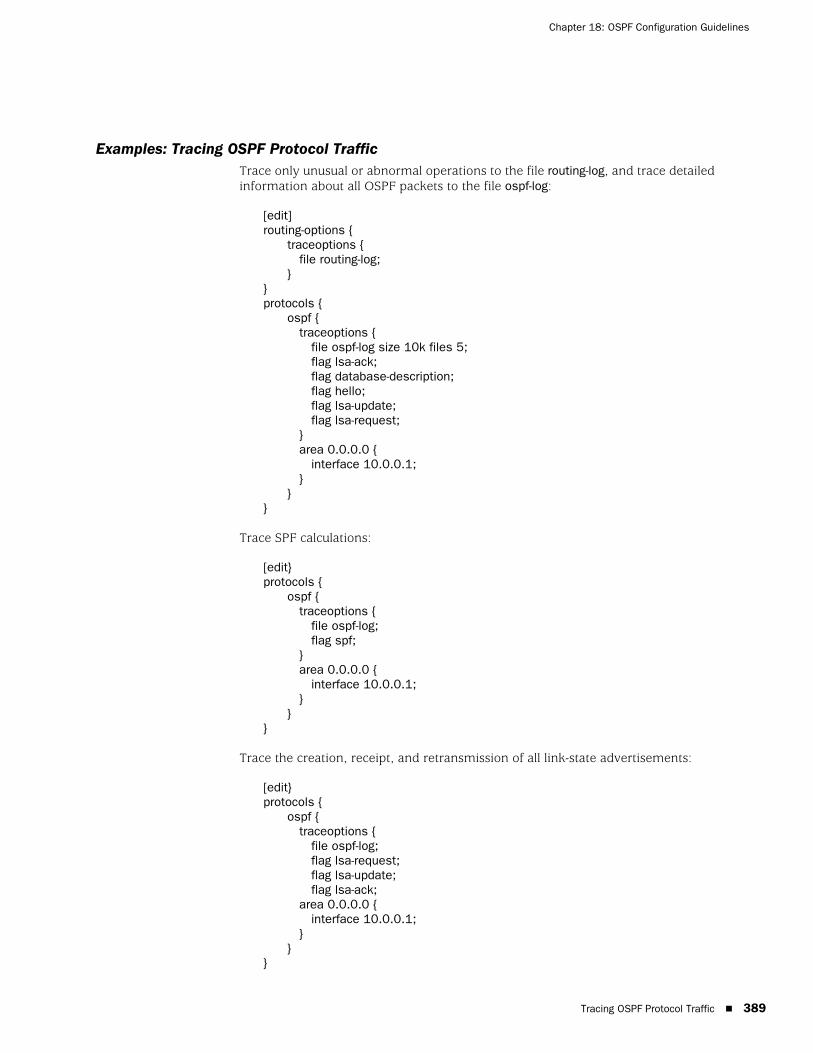
Examples: Tracing OSPF Protocol TrafficTrace only unusual or abnormal operations to the file routing-log, and trace detailedinformation about all OSPF packets to the file ospf-log:
[edit]routing-options {
traceoptions {file routing-log;
}}protocols {
ospf {traceoptions {
file ospf-log size 10k files 5;flag lsa-ack;flag database-description;flag hello;flag lsa-update;flag lsa-request;
}area 0.0.0.0 {
interface 10.0.0.1;}
}}
Trace SPF calculations:
[edit}protocols {
ospf {traceoptions {
file ospf-log;flag spf;
}area 0.0.0.0 {
interface 10.0.0.1;}
}}
Trace the creation, receipt, and retransmission of all link-state advertisements:
[edit}protocols {
ospf {traceoptions {
file ospf-log;flag lsa-request;flag lsa-update;flag lsa-ack;
area 0.0.0.0 {interface 10.0.0.1;
}}
}
Tracing OSPF Protocol Traffic � 389

JUNOS 8.2 Routing Protocols Configuration Guide
390 �
Tracing OSPF Protocol Traffic