Embed Size (px)
Citation preview
Chapter 15 Network Address Translation
(9300 Series Only)
You can configure a ProCurve Routing Switch to perform standard Network Address Translation (NAT). The following types of NAT are supported:
• Inside source NAT – Enables private IP networks that use nonregistered IP addresses to connect to the Internet.
• Inside destination NAT – Enables you to translate the global (Internet) IP addresses of traffic received from those addresses into private addresses.
NOTE: If you want to use NAT and ACLs on the same port, see “Using ACLs and Network Address Translation (NAT) on the Same Interface (9300 Series Only)” on page 4-6 for important guidelines.
Protocols Supported for NAT HP NAT supports the following protocols:
• ICMP
• UDP/TCP (generic)
• FTP
• VDOLive
• StreamWorks
• CU-SeeMe
• RealAudio and RealVideo
• RealMedia
• QuickTime
• Microsoft Media Services
• Web Theater (Vxtreme)
NOTE: HP does not support streaming protocols, such as RTSP/MMS, if IP NAT inside destination static is configured.
June 2005 15 - 1
Advanced Configuration and Management Guide for ProCurve 9300/9400 Series Routing Switches
NOTE: When configured for inside destination NAT, the HP device does not translate ICMP echo request packets from outside addresses to inside hosts. Instead, the device itself replies to the ping requests. The device does translate other types of ICMP packets.
Port Address Translation Normally, NAT maps each address that needs to be translated to a unique IP address from a pool. However, it is possible for the address pool to have fewer addresses than the number of addresses you might need. In this case, you can configure the HP device to use Port Address Translation. Port Address Translation maps a client’s IP address and TCP or UDP port number to both an IP address and a TCP or UDP port number. In this way, the HP device can map many addresses to the same address and use TCP or UDP port numbers to uniquely identify the private hosts.
NOTE: This type of feature is sometimes called Port Overload.
In the example in Figure 15.1, a pool configured for inside source NAT contains enough addresses to ensure that every host on the private network can be mapped to an Internet address in the pool. However, suppose the enterprise implementing this configuration has only 20 Internet addresses. For example, the pool might be 209.157.1.1/24 – 209.157.1.20/24. In this case, the pool does not contain enough addresses to ensure that all the hosts in the private network can be mapped to Internet addresses.
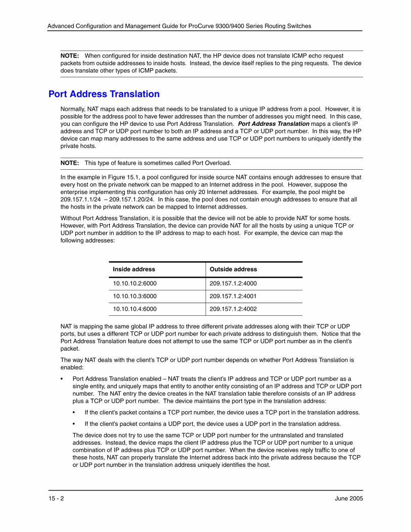
Without Port Address Translation, it is possible that the device will not be able to provide NAT for some hosts. However, with Port Address Translation, the device can provide NAT for all the hosts by using a unique TCP or UDP port number in addition to the IP address to map to each host. For example, the device can map the following addresses:
Inside address
10.10.10.2:6000
10.10.10.3:6000
10.10.10.4:6000
Outside address
209.157.1.2:4000
209.157.1.2:4001
209.157.1.2:4002
NAT is mapping the same global IP address to three different private addresses along with their TCP or UDP ports, but uses a different TCP or UDP port number for each private address to distinguish them. Notice that the Port Address Translation feature does not attempt to use the same TCP or UDP port number as in the client’s packet.
The way NAT deals with the client’s TCP or UDP port number depends on whether Port Address Translation is enabled:
• Port Address Translation enabled – NAT treats the client’s IP address and TCP or UDP port number as a single entity, and uniquely maps that entity to another entity consisting of an IP address and TCP or UDP port number. The NAT entry the device creates in the NAT translation table therefore consists of an IP address plus a TCP or UDP port number. The device maintains the port type in the translation address:
• If the client’s packet contains a TCP port number, the device uses a TCP port in the translation address.
• If the client’s packet contains a UDP port, the device uses a UDP port in the translation address.
The device does not try to use the same TCP or UDP port number for the untranslated and translated addresses. Instead, the device maps the client IP address plus the TCP or UDP port number to a unique combination of IP address plus TCP or UDP port number. When the device receives reply traffic to one of these hosts, NAT can properly translate the Internet address back into the private address because the TCP or UDP port number in the translation address uniquely identifies the host.
15 - 2 June 2005
Network Address Translation (9300 Series Only)
To enable Port Address Translation, use the overload option when you configure the source list, which associates a private address range with a pool of Internet addresses. See “Configuring Dynamic NAT Parameters” on page 15-6.
• Port Address Translation disabled – The device translates only the client’s IP address into another IP address and retains the TCP or UDP port number unchanged.
Maximum Number of Addresses If the Routing Switch cannot allocate an address because it has run out of addresses, the Routing Switch drops the packet and sends an ICMP Host Unreachable packet.
NOTE: The maximum number of global IP addresses you can configure for inside source NAT depends on how much memory the Routing Switch has and whether you enable the Port Address Translation feature. Regardless of the amount of memory, you cannot configure more than 256 global IP addresses.
Inside Source NAT Inside source NAT enables private IP networks that use nonregistered IP addresses to connect to the Internet. Configure the NAT on the HP device at the border of an inside network and an outside network (such as the Internet). Inside source NAT translates the internal local addresses to globally unique IP addresses before sending packets to the outside network. Inside source NAT also allows a more graceful renumbering strategy for organizations that are changing service providers or voluntarily renumbering into Classless Interdomain Routing (CIDR) blocks.
Use inside source NAT to translate your private (inside) IP addresses into globally unique (outside) IP addresses when communicating outside of your network.
NOTE: This feature is supported on the 9300 series Routing Switches with Management 2 modules or higher.
NOTE: The maximum number of global IP addresses you can configure depends on how much memory the Routing Switch has and whether you enable the Port Address Translation feature. Regardless of the amount of memory, you cannot configure more than 256 global IP addresses.
An HP device configured for NAT must have an interface to the private network and an interface to a public network (for example, the Internet). In a typical environment, NAT is configured on the HP device between the private network and the Internet. When you configure an HP device for NAT, the device does not advertise the private networks to the Internet. However, the device can advertise route information received from the Internet to the private networks.
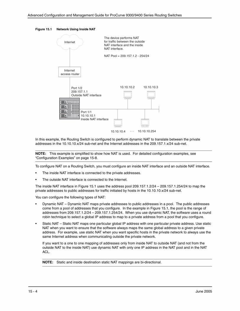
Figure 15.1 shows a basic example of a network using NAT on an HP device. In this example, an 9308M Routing Switch is using NAT to translate traffic originated from the hosts on the 10.10.10.x/24 sub-net into public addresses from the address pool.
June 2005 15 - 3
Advanced Configuration and Management Guide for ProCurve 9300/9400 Series Routing Switches
Figure 15.1 Network Using Inside NAT
10.10.10.3
209.157.1.1
10.10.10.2
access router
10.10.10.1
Port 1/2
Outside NAT interface
Internet The device performs NAT for traffic between the outside NAT interface and the inside NAT interface.
NAT Pool = 209.157.1.2 - 254/24
Internet
Port 1/1
Inside NAT interface
10.10.10.4 . . . 10.10.10.254
In this example, the Routing Switch is configured to perform dynamic NAT to translate between the private addresses in the 10.10.10.x/24 sub-net and the Internet addresses in the 209.157.1.x/24 sub-net.
NOTE: This example is simplified to show how NAT is used. For detailed configuration examples, see “Configuration Examples” on page 15-8.
To configure NAT on a Routing Switch, you must configure an inside NAT interface and an outside NAT interface.
• The inside NAT interface is connected to the private addresses.
• The outside NAT interface is connected to the Internet.
The inside NAT interface in Figure 15.1 uses the address pool 209.157.1.2/24 – 209.157.1.254/24 to map the private addresses to public addresses for traffic initiated by hosts in the 10.10.10.x/24 sub-net.
You can configure the following types of NAT:
• Dynamic NAT – Dynamic NAT maps private addresses to public addresses in a pool. The public addresses come from a pool of addresses that you configure. In the example in Figure 15.1, the pool is the range of addresses from 209.157.1.2/24 – 209.157.1.254/24. When you use dynamic NAT, the software uses a round robin technique to select a global IP address to map to a private address from a pool that you configure.
• Static NAT – Static NAT maps one particular global IP address with one particular private address. Use static NAT when you want to ensure that the software always maps the same global address to a given private address. For example, use static NAT when you want specific hosts in the private network to always use the same Internet address when communicating outside the private network.
If you want to a one to one mapping of addresses only from inside NAT to outside NAT (and not from the outside NAT to the inside NAT) use dynamic NAT with only one IP address in the NAT pool and in the NAT ACL.
NOTE: Static and inside destination static NAT mappings are bi-directional.
15 - 4 June 2005
Network Address Translation (9300 Series Only)
NOTE: You can configure both dynamic and static NAT on the same HP device. When you configure both types of NAT, static NAT takes precedence over dynamic NAT. Thus, if you configure a static NAT translation for a private address, the device always uses that translation instead of creating a dynamic one.
Configuring Source NAT To configure NAT, perform the following tasks:
• Configure the static address mappings, if needed. Static mappings explicitly map a specific private address to a specific Internet address to ensure that the addresses are always mapped together. Use static address mappings when you want to ensure that a specific host in the private network is always mapped to the Internet address you specify.
• Configure dynamic NAT parameters:
• Configure a standard or extended ACL for each range of private addresses for which you want to provide NAT.
• Configure a pool for each consecutive range of Internet addresses to which you want NAT to be able to map the private addresses specified in the ACLs. Each pool must contain a range with no gaps. If your Internet address space has gaps, configure separate pools for each consecutive range within the address space.
• Associate a range of private addresses (specified in a standard or extended ACL) with a pool.
• Optionally, enable the Port Address Translation feature. Use this feature if you have more private addresses that might need NAT than the Internet address pools contain.
NOTE: If you plan to use dynamic NAT without the Port Address Translation feature, contact your HP account representative for additional requirements that may apply to your installation.
• Enable inside NAT on the interface connected to the private addresses.
• Enable outside NAT on the interface connected to global addresses.
The configuration does not take effect until you enable inside and outside NAT on specific interfaces.
NOTE: You must configure inside NAT on one interface and outside NAT on another interface. The device performs NAT for traffic between the interfaces.
NOTE: Named ACLS are not supported with NAT. You must use a numbered ACL.
In addition to the tasks listed above, you can modify the age timers for the address translation entries the device creates. See “Changing Translation Table Timeouts” on page 15-16 for information. For information about viewing the active NAT translations, see “Displaying the Active NAT Translations” on page 15-17.
The following sections provide procedures for configuring NAT.
Configuring Static Address Translations
Use the following CLI method to configure static NAT.
USING THE CLI
To configure static NAT for an IP address, enter a command such as the following:
ProCurveRS(config)# ip nat inside source static 10.10.10.69 209.157.1.69
The command in this example statically maps the private address 10.10.10.69 to the Internet address 209.157.1.69.
Syntax: [no] ip nat inside source static <private-ip> <global-ip>
June 2005 15 - 5

Advanced Configuration and Management Guide for ProCurve 9300/9400 Series Routing Switches
This command associates a specific private address with a specific Internet address. Use this command whenyou want to ensure that the specified addresses are always mapped together.
The inside source parameter specifies that the mapping applies to the private address sending traffic to theInternet.
The <private-ip> parameter specifies the private IP address.
The <global-ip> parameter specifies the Internet address. The device supports up to 256 global IP addresses.
Neither of the IP address parameters needs a network mask.
Configuring Dynamic NAT Parameters
To configure dynamic NAT:
• Configure a standard or extended ACL for each private address range.
NOTE: Named ACLS are not supported with NAT. You must use a numbered ACL.
• Configure a pool for each consecutive range of Internet addresses.
• Associate private addresses (ACLs) with pools.
• Optionally, enable the Port Address Translation feature.
NOTE: If you plan to use dynamic NAT without the Port Address Translation feature, contact your HP account representative for additional requirements that may apply to your installation.
Use the following CLI method to configure dynamic NAT.
USING THE CLI
You can configure dynamic NAT with the Port Address Translation feature disabled or enabled.
Example with Port Address Translation Disabled
NOTE: If you plan to use dynamic NAT without the Port Address Translation feature, contact your HP account representative for additional requirements that may apply to your installation.
To configure dynamic NAT with the Port Address Translation feature disabled, enter commands such as the following at the global CONFIG level of the CLI:
ProCurveRS(config)# access-list 1 permit 10.10.10.0/24 ProCurveRS(config)# ip nat pool OutAdds 209.157.1.2 209.157.1.254 prefix-length 24 ProCurveRS(config)# ip nat inside source list 1 pool OutAdds
These commands configure a standard ACL for the private sub-net 10.10.10.x/24, then enable inside NAT for the sub-net. Make sure you specify permit in the ACL, rather than deny. If you specify deny, the HP device will not provide NAT for the addresses.
Example with Port Address Translation Enabled To configure dynamic NAT with the Port Address Translation feature enabled, enter commands such as the following at the global CONFIG level of the CLI:
ProCurveRS(config)# access-list 1 permit 10.10.10.0/24 ProCurveRS(config)# ip nat pool OutAdds 209.157.1.2 209.157.1.254 prefix-length 24 ProCurveRS(config)# ip nat inside source list 1 pool OutAdds overload
These commands are the same as the ones in “Example with Port Address Translation Disabled”, except the ip nat inside source command uses the overload parameter. This parameter enables the Port Address Translation feature.
Command Syntax Syntax: [no] ip nat pool <pool-name> <start-ip> <end-ip> netmask <ip-mask> | prefix-length <length> [type match-host | rotary]
15 - 6 June 2005
Network Address Translation (9300 Series Only)
This command configures the address pool.
The <pool-name> parameter specifies the pool name. The name can be up to 255 characters long and can contain special characters and internal blanks. If you use internal blanks, you must use quotation marks around the entire name.
The <start-ip> parameter specifies the IP address at the beginning of the pool range. Specify the lowestnumbered IP address in the range.
The <end-ip> parameter specifies the IP address at the end of the pool range. Specify the highest-numbered IP address in the range.
NOTE: The address range cannot contain any gaps. Make sure you own all the IP addresses in the range. If the range contains gaps, you must create separate pools containing only the addresses you own.
The netmask <ip-mask> | prefix-length <length> parameter specifies a classical sub-net mask (example: netmask 255.255.255.0) or the length of a Classless Interdomain Routing prefix (example: prefix-length 24).
NOTE: The maximum number of global IP addresses you can configure depends on how much memory the Routing Switch has and whether you enable the Port Address Translation feature. Regardless of the amount of memory, you cannot configure more than 256 global IP addresses.
The type match-host | rotary parameter specifies the method the software uses to assign the host portion of the translated address.
• match-host – The software uses the same host address as the untranslated address. For example, if the untranslated address is 192.2.4.69 and the host portion of the address is 69, the translated address also uses the host address 69. This method results in the translated addresses always having the same host addresses as their untranslated counterparts.
• rotary – The software assigns a host address from 1 – 254, beginning with 1 for the first translated address. This is the default.
Syntax: [no] ip nat inside source list <acl-id> pool <pool-name> [overload]
This command associates a private address range with a pool of Internet addresses and optionally enables the Port Address Translation feature.
The inside source parameter specifies that the translation applies to private addresses sending traffic to global addresses (Internet addresses).
The list <acl-id> parameter specifies a standard or extended ACL. You can specify a numbered or named ACL.
NOTE: Named ACLS are not supported with NAT. You must use a numbered ACL.
NOTE: For complete standard and extended ACL syntax, see “Software-Based IP Access Control Lists (ACLs)” on page 4-1.
The pool <pool-name> parameter specifies the pool. You must create the pool before you can use it with this command.
The overload parameter enables the Port Address Translation feature. Use this parameter if the IP address pool does not contain enough addresses to ensure NAT for each private address. The Port Address Translation feature conserves Internet addresses by mapping the same Internet address to more than one private address and using a TCP or UDP port number to distinguish among the private hosts. The device supports up to 50 global IP addresses with this feature enabled.
Enabling NAT
The NAT configuration does not take effect until you enable it on specific interfaces. You can enable NAT on Ethernet ports and on virtual interfaces. You also can enable the feature on the primary port of a trunk group, in which case the feature applies to all the ports in the trunk group.
June 2005 15 - 7
Advanced Configuration and Management Guide for ProCurve 9300/9400 Series Routing Switches
NOTE: You must configure inside NAT on one interface and outside NAT on another interface. The device performs NAT for traffic between the interfaces.
To enable NAT, use the following CLI methods.
Enabling Inside NAT To enable inside NAT on the interface attached to the private addresses, use the following CLI method.
USING THE CLI
To enable inside NAT on an interface, enter commands such as the following:
ProCurveRS(config)# interface ethernet 1/1 ProCurveRS(config-if-1/1)# ip nat inside
This command enables inside NAT on Ethernet port 1/1.
Syntax: [no] ip nat inside
To enable inside NAT on a virtual interface, enter commands such as the following:
ProCurveRS(config)# interface ve 1 ProCurveRS(config-vif-1)# ip nat inside
This command enables inside NAT on virtual interface 4.
Enabling Outside NAT To enable outside NAT on the interface attached to public addresses, use the following CLI method.
USING THE CLI
To enable outside NAT on an interface, enter commands such as the following:
ProCurveRS(config)# interface ethernet 1/2 ProCurveRS(config-if-1/2)# ip nat outside
This command enables outside NAT on Ethernet port 1/2.
Syntax: [no] ip nat outside
To enable outside NAT on a virtual interface, enter commands such as the following:
ProCurveRS(config)# interface ve 2 ProCurveRS(config-vif-2)# ip nat outside
This command enables outside NAT on virtual interface 4.
Configuration Examples This section shows two complete configuration examples for NAT. The examples are based on different network topologies.
• NAT clients connected to the Routing Switch by an HP Switch.
• NAT clients connected directly to Routing Switch ports.
NOTE: You also can enable the feature on the primary port of a trunk group, in which case the feature applies to all the ports in the trunk group. These examples do not show this configuration.
Private NAT Clients Connected to the Routing Switch by a Switch
Figure 15.2 shows an example of a NAT configuration in which the clients in the private network are attached to the Routing Switch through an HP Switch.
15 - 8 June 2005
Network Address Translation (9300 Series Only)
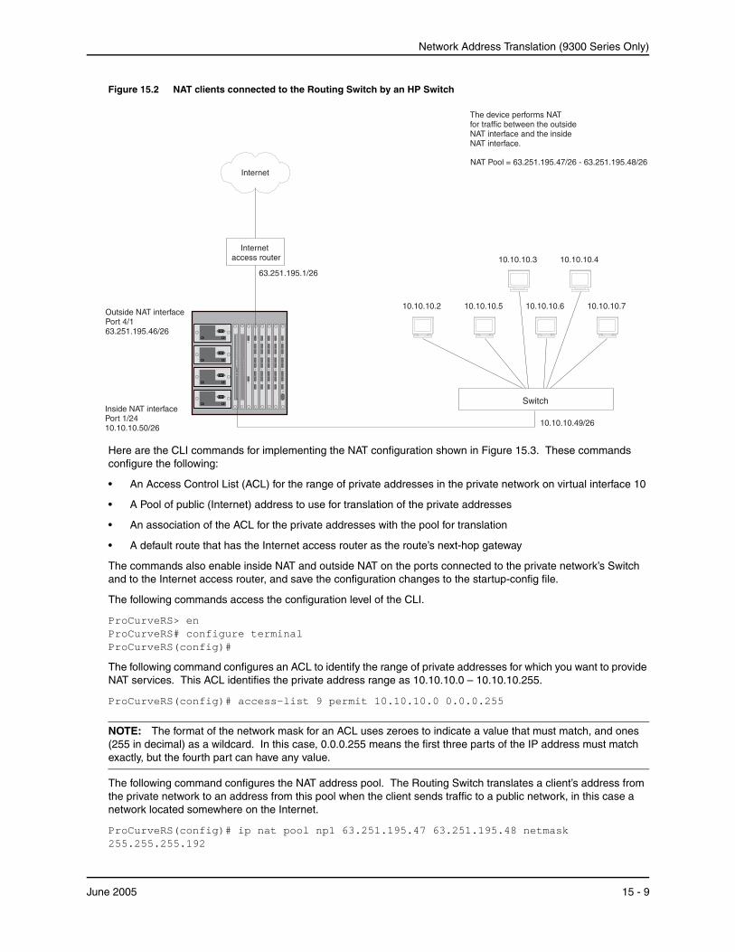
Figure 15.2 NAT clients connected to the Routing Switch by an HP Switch
The device performs NAT for traffic between the outside NAT interface and the inside NAT interface.
10.10.10.7
access router
10.10.10.610.10.10.5
10.10.10.410.10.10.3
10.10.10.2
10.10.10.49/26
63.251.195.46/26
10.10.10.50/26
63.251.195.1/26
Switch
Internet NAT Pool = 63.251.195.47/26 - 63.251.195.48/26
Internet
Outside NAT interface Port 4/1
Inside NAT interface Port 1/24
Here are the CLI commands for implementing the NAT configuration shown in Figure 15.3. These commands configure the following:
• An Access Control List (ACL) for the range of private addresses in the private network on virtual interface 10
• A Pool of public (Internet) address to use for translation of the private addresses
• An association of the ACL for the private addresses with the pool for translation
• A default route that has the Internet access router as the route’s next-hop gateway
The commands also enable inside NAT and outside NAT on the ports connected to the private network’s Switch and to the Internet access router, and save the configuration changes to the startup-config file.
The following commands access the configuration level of the CLI.
ProCurveRS> en ProCurveRS# configure terminal ProCurveRS(config)#
The following command configures an ACL to identify the range of private addresses for which you want to provide NAT services. This ACL identifies the private address range as 10.10.10.0 – 10.10.10.255.
ProCurveRS(config)# access-list 9 permit 10.10.10.0 0.0.0.255
NOTE: The format of the network mask for an ACL uses zeroes to indicate a value that must match, and ones (255 in decimal) as a wildcard. In this case, 0.0.0.255 means the first three parts of the IP address must match exactly, but the fourth part can have any value.
The following command configures the NAT address pool. The Routing Switch translates a client’s address from the private network to an address from this pool when the client sends traffic to a public network, in this case a network located somewhere on the Internet.
ProCurveRS(config)# ip nat pool np1 63.251.195.47 63.251.195.48 netmask 255.255.255.192
June 2005 15 - 9
Advanced Configuration and Management Guide for ProCurve 9300/9400 Series Routing Switches
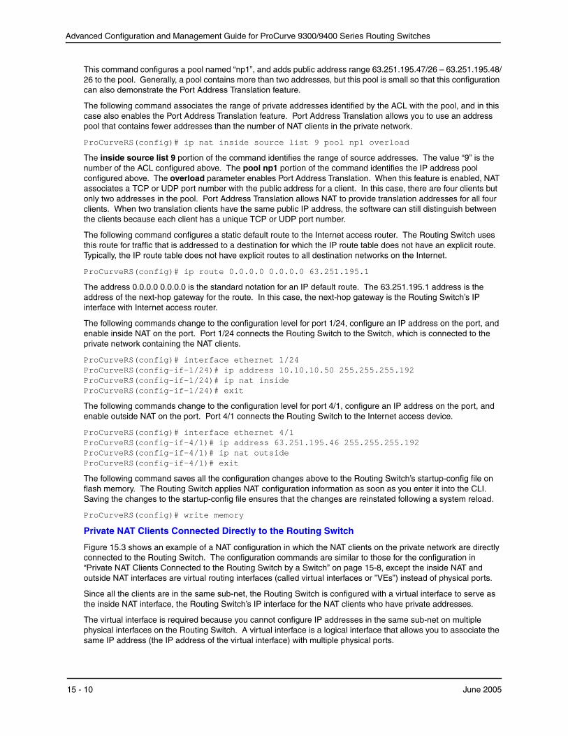
This command configures a pool named “np1”, and adds public address range 63.251.195.47/26 – 63.251.195.48/ 26 to the pool. Generally, a pool contains more than two addresses, but this pool is small so that this configuration can also demonstrate the Port Address Translation feature.
The following command associates the range of private addresses identified by the ACL with the pool, and in this case also enables the Port Address Translation feature. Port Address Translation allows you to use an address pool that contains fewer addresses than the number of NAT clients in the private network.
ProCurveRS(config)# ip nat inside source list 9 pool np1 overload
The inside source list 9 portion of the command identifies the range of source addresses. The value “9” is the number of the ACL configured above. The pool np1 portion of the command identifies the IP address pool configured above. The overload parameter enables Port Address Translation. When this feature is enabled, NAT associates a TCP or UDP port number with the public address for a client. In this case, there are four clients but only two addresses in the pool. Port Address Translation allows NAT to provide translation addresses for all four clients. When two translation clients have the same public IP address, the software can still distinguish between the clients because each client has a unique TCP or UDP port number.
The following command configures a static default route to the Internet access router. The Routing Switch uses this route for traffic that is addressed to a destination for which the IP route table does not have an explicit route. Typically, the IP route table does not have explicit routes to all destination networks on the Internet.
ProCurveRS(config)# ip route 0.0.0.0 0.0.0.0 63.251.195.1
The address 0.0.0.0 0.0.0.0 is the standard notation for an IP default route. The 63.251.195.1 address is the address of the next-hop gateway for the route. In this case, the next-hop gateway is the Routing Switch’s IP interface with Internet access router.
The following commands change to the configuration level for port 1/24, configure an IP address on the port, and enable inside NAT on the port. Port 1/24 connects the Routing Switch to the Switch, which is connected to the private network containing the NAT clients.
ProCurveRS(config)# interface ethernet 1/24 ProCurveRS(config-if-1/24)# ip address 10.10.10.50 255.255.255.192 ProCurveRS(config-if-1/24)# ip nat inside ProCurveRS(config-if-1/24)# exit
The following commands change to the configuration level for port 4/1, configure an IP address on the port, and enable outside NAT on the port. Port 4/1 connects the Routing Switch to the Internet access device.
ProCurveRS(config)# interface ethernet 4/1 ProCurveRS(config-if-4/1)# ip address 63.251.195.46 255.255.255.192 ProCurveRS(config-if-4/1)# ip nat outside ProCurveRS(config-if-4/1)# exit
The following command saves all the configuration changes above to the Routing Switch’s startup-config file on flash memory. The Routing Switch applies NAT configuration information as soon as you enter it into the CLI. Saving the changes to the startup-config file ensures that the changes are reinstated following a system reload.
ProCurveRS(config)# write memory
Private NAT Clients Connected Directly to the Routing Switch
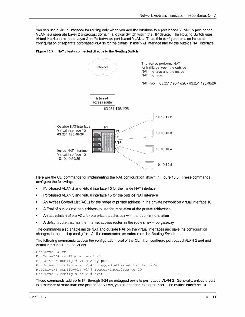
Figure 15.3 shows an example of a NAT configuration in which the NAT clients on the private network are directly connected to the Routing Switch. The configuration commands are similar to those for the configuration in “Private NAT Clients Connected to the Routing Switch by a Switch” on page 15-8, except the inside NAT and outside NAT interfaces are virtual routing interfaces (called virtual interfaces or ”VEs”) instead of physical ports.
Since all the clients are in the same sub-net, the Routing Switch is configured with a virtual interface to serve as the inside NAT interface, the Routing Switch’s IP interface for the NAT clients who have private addresses.
The virtual interface is required because you cannot configure IP addresses in the same sub-net on multiple physical interfaces on the Routing Switch. A virtual interface is a logical interface that allows you to associate the same IP address (the IP address of the virtual interface) with multiple physical ports.
15 - 10 June 2005
Network Address Translation (9300 Series Only)
You can use a virtual interface for routing only when you add the interface to a port-based VLAN. A port-based VLAN is a separate Layer 2 broadcast domain, a logical Switch within the HP device. The Routing Switch uses virtual interfaces to route Layer 3 traffic between port-based VLANs. Thus, this configuration also includes configuration of separate port-based VLANs for the clients’ inside NAT interface and for the outside NAT interface.
Figure 15.3 NAT clients connected directly to the Routing Switch
Internet The device performs NAT for traffic between the outside NAT interface and the inside NAT interface.
NAT Pool = 63.251.195.47/26 - 63.251.195.48/26
Internet access router
63.251.195.1/26
10.10.10.3
10.10.10.5
10.10.10.4
10.10.10.50/26
10.10.10.2
8/9 8/16
8/24
1/1
63.251.195.46/26 8/1
Inside NAT interface Virtual interface 10
Outside NAT interface Virtual interface 15
Here are the CLI commands for implementing the NAT configuration shown in Figure 15.3. These commands configure the following:
• Port-based VLAN 2 and virtual interface 10 for the inside NAT interface
• Port-based VLAN 3 and virtual interface 15 for the outside NAT interface
• An Access Control List (ACL) for the range of private address in the private network on virtual interface 10
• A Pool of public (Internet) address to use for translation of the private addresses
• An association of the ACL for the private addresses with the pool for translation
• A default route that has the Internet access router as the route’s next-hop gateway
The commands also enable inside NAT and outside NAT on the virtual interfaces and save the configuration changes to the startup-config file. All the commands are entered on the Routing Switch.
The following commands access the configuration level of the CLI, then configure port-based VLAN 2 and add virtual interface 10 to the VLAN.
ProCurveRS> en ProCurveRS# configure terminal ProCurveRS(config)# vlan 2 by port ProCurveRS(config-vlan-2)# untagged ethernet 8/1 to 8/24 ProCurveRS(config-vlan-2)# router-interface ve 10 ProCurveRS(config-vlan-2)# exit
These commands add ports 8/1 through 8/24 as untagged ports to port-based VLAN 2. Generally, unless a port is a member of more than one port-based VLAN, you do not need to tag the port. The router-interface 10
June 2005 15 - 11
Advanced Configuration and Management Guide for ProCurve 9300/9400 Series Routing Switches
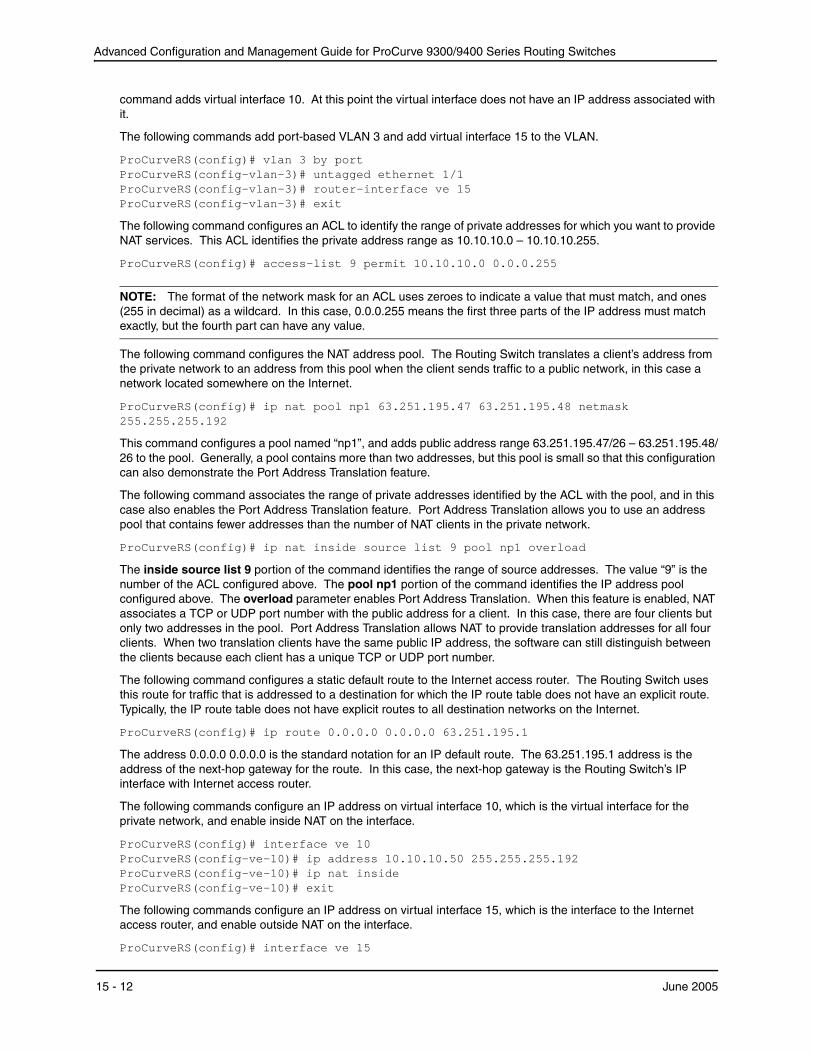
command adds virtual interface 10. At this point the virtual interface does not have an IP address associated with it.
The following commands add port-based VLAN 3 and add virtual interface 15 to the VLAN.
ProCurveRS(config)# vlan 3 by port ProCurveRS(config-vlan-3)# untagged ethernet 1/1 ProCurveRS(config-vlan-3)# router-interface ve 15 ProCurveRS(config-vlan-3)# exit
The following command configures an ACL to identify the range of private addresses for which you want to provide NAT services. This ACL identifies the private address range as 10.10.10.0 – 10.10.10.255.
ProCurveRS(config)# access-list 9 permit 10.10.10.0 0.0.0.255
NOTE: The format of the network mask for an ACL uses zeroes to indicate a value that must match, and ones (255 in decimal) as a wildcard. In this case, 0.0.0.255 means the first three parts of the IP address must match exactly, but the fourth part can have any value.
The following command configures the NAT address pool. The Routing Switch translates a client’s address from the private network to an address from this pool when the client sends traffic to a public network, in this case a network located somewhere on the Internet.
ProCurveRS(config)# ip nat pool np1 63.251.195.47 63.251.195.48 netmask 255.255.255.192
This command configures a pool named “np1”, and adds public address range 63.251.195.47/26 – 63.251.195.48/ 26 to the pool. Generally, a pool contains more than two addresses, but this pool is small so that this configuration can also demonstrate the Port Address Translation feature.
The following command associates the range of private addresses identified by the ACL with the pool, and in this case also enables the Port Address Translation feature. Port Address Translation allows you to use an address pool that contains fewer addresses than the number of NAT clients in the private network.
ProCurveRS(config)# ip nat inside source list 9 pool np1 overload
The inside source list 9 portion of the command identifies the range of source addresses. The value “9” is the number of the ACL configured above. The pool np1 portion of the command identifies the IP address pool configured above. The overload parameter enables Port Address Translation. When this feature is enabled, NAT associates a TCP or UDP port number with the public address for a client. In this case, there are four clients but only two addresses in the pool. Port Address Translation allows NAT to provide translation addresses for all four clients. When two translation clients have the same public IP address, the software can still distinguish between the clients because each client has a unique TCP or UDP port number.
The following command configures a static default route to the Internet access router. The Routing Switch uses this route for traffic that is addressed to a destination for which the IP route table does not have an explicit route. Typically, the IP route table does not have explicit routes to all destination networks on the Internet.
ProCurveRS(config)# ip route 0.0.0.0 0.0.0.0 63.251.195.1
The address 0.0.0.0 0.0.0.0 is the standard notation for an IP default route. The 63.251.195.1 address is the address of the next-hop gateway for the route. In this case, the next-hop gateway is the Routing Switch’s IP interface with Internet access router.
The following commands configure an IP address on virtual interface 10, which is the virtual interface for the private network, and enable inside NAT on the interface.
ProCurveRS(config)# interface ve 10 ProCurveRS(config-ve-10)# ip address 10.10.10.50 255.255.255.192 ProCurveRS(config-ve-10)# ip nat inside ProCurveRS(config-ve-10)# exit
The following commands configure an IP address on virtual interface 15, which is the interface to the Internet access router, and enable outside NAT on the interface.
ProCurveRS(config)# interface ve 15
15 - 12 June 2005

Network Address Translation (9300 Series Only)
ProCurveRS(config-ve-15)# ip address 63.251.195.46 255.255.255.192ProCurveRS(config-ve-15)# ip nat outsideProCurveRS(config-ve-15)# exit
The following command saves all the configuration changes above to the Routing Switch’s startup-config file on flash memory. The Routing Switch applies NAT configuration information as soon as you enter it into the CLI. Saving the changes to the startup-config file ensures that the changes are reinstated following a system reload.
ProCurveRS(config)# write memory
Inside Destination NAT Inside destination NAT translates the global (Internet) IP addresses of traffic received from those addresses into private addresses. You can use the feature to associate an application, such as email, with a specific internal host. The feature also can provide load balancing for services by mapping traffic addressed to the services to a pool of internal addresses, and thus to different hosts.
Use the feature on a Routing Switch that has at least one interface to the private network and another interface to the Internet. For example, use this feature on a Routing Switch that connects a stub domain to the backbone
You can configure either of the following types of inside destination NAT:
• Dynamic NAT – Dynamic NAT maps global addresses to private addresses, which are in a pool that you configure. When you use dynamic NAT, the software uses a round robin technique to select the private addresses from the pool.
• Static NAT – Static NAT maps a particular private address to a particular global address. Use static NAT when you want to ensure that the software always maps the same private address to a given global address. Optionally, you also can map traffic based on TCP or UDP application ports, to provide NAT for specific applications.
NOTE: You can configure both dynamic and static inside destination NAT on the same HP device. When you configure both types of NAT, static NAT takes precedence over dynamic NAT. If you configure a static NAT translation for an address, the device always uses that translation instead of creating a dynamic one.
Configuring Inside Destination NAT To configure inside destination NAT:
• Configure the static address mappings, if needed. Static mappings explicitly map a specific public address to a specific private address to ensure that the addresses are always mapped together. Use static address mappings when you want to ensure that a specific public host is always mapped to a specific private host.
• Configure dynamic NAT parameters:
• Configure an IP ACL (standard or extended) for each range of public addresses for which you want to provide NAT.
• Configure a pool for each consecutive range of private addresses to which you want NAT to be able to map the public addresses specified in the ACLs. Each pool must contain a range with no gaps. If your private address space has gaps, configure separate pools for each consecutive range within the address space.
• Associate a range of public addresses (specified in an IP ACL) with a pool.
• Enable inside destination NAT on the interface connected to the private addresses.
• Enable outside NAT on the interface connected to global addresses.
The configuration does not take effect until you enable inside destination and outside NAT on specific interfaces.
Configuring Static Inside Destination NAT for IP Addresses Only
To configure static inside destination NAT for an IP address, enter a command such as the following:
June 2005 15 - 13
Advanced Configuration and Management Guide for ProCurve 9300/9400 Series Routing Switches
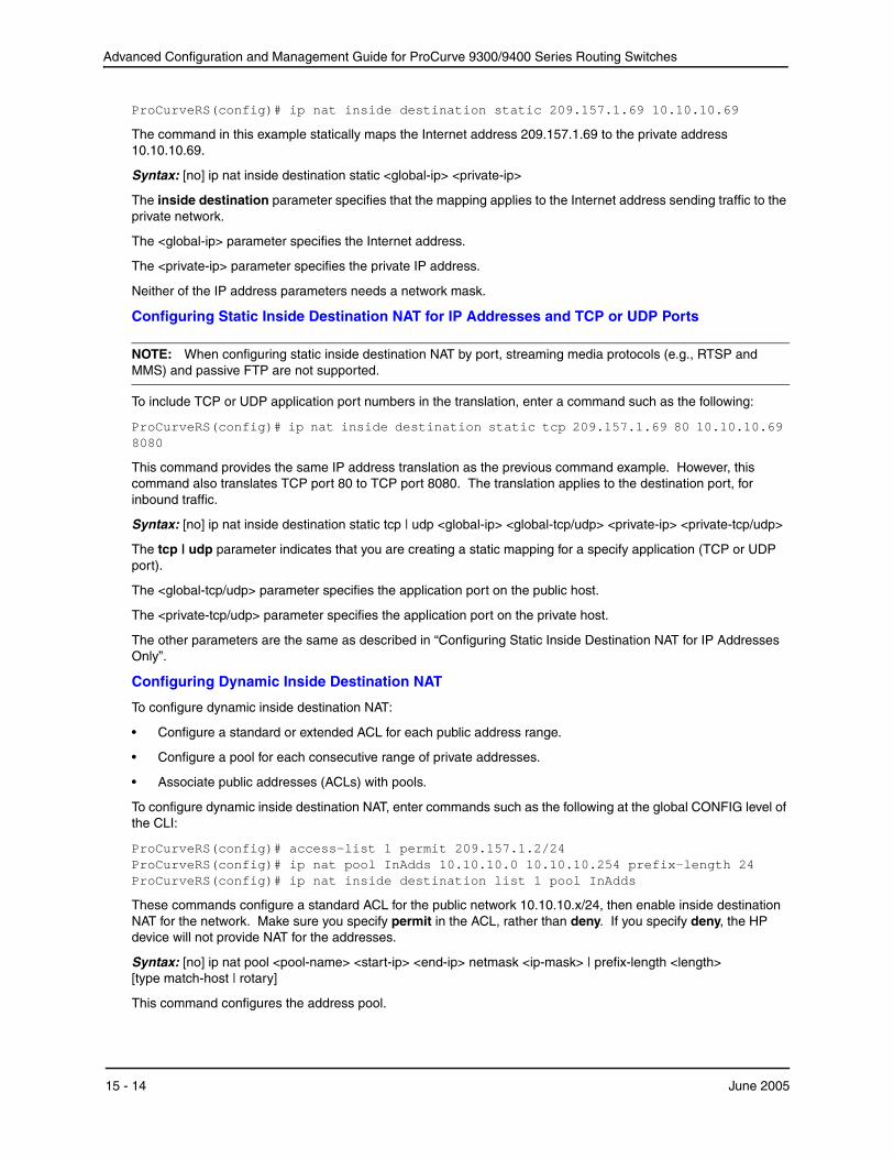
ProCurveRS(config)# ip nat inside destination static 209.157.1.69 10.10.10.69
The command in this example statically maps the Internet address 209.157.1.69 to the private address 10.10.10.69.
Syntax: [no] ip nat inside destination static <global-ip> <private-ip>
The inside destination parameter specifies that the mapping applies to the Internet address sending traffic to theprivate network.
The <global-ip> parameter specifies the Internet address.
The <private-ip> parameter specifies the private IP address.
Neither of the IP address parameters needs a network mask.
Configuring Static Inside Destination NAT for IP Addresses and TCP or UDP Ports
NOTE: When configuring static inside destination NAT by port, streaming media protocols (e.g., RTSP and MMS) and passive FTP are not supported.
To include TCP or UDP application port numbers in the translation, enter a command such as the following:
ProCurveRS(config)# ip nat inside destination static tcp 209.157.1.69 80 10.10.10.69 8080
This command provides the same IP address translation as the previous command example. However, this command also translates TCP port 80 to TCP port 8080. The translation applies to the destination port, for inbound traffic.
Syntax: [no] ip nat inside destination static tcp | udp <global-ip> <global-tcp/udp> <private-ip> <private-tcp/udp>
The tcp | udp parameter indicates that you are creating a static mapping for a specify application (TCP or UDP port).
The <global-tcp/udp> parameter specifies the application port on the public host.
The <private-tcp/udp> parameter specifies the application port on the private host.
The other parameters are the same as described in “Configuring Static Inside Destination NAT for IP Addresses Only”.
Configuring Dynamic Inside Destination NAT
To configure dynamic inside destination NAT:
• Configure a standard or extended ACL for each public address range.
• Configure a pool for each consecutive range of private addresses.
• Associate public addresses (ACLs) with pools.
To configure dynamic inside destination NAT, enter commands such as the following at the global CONFIG level of the CLI:
ProCurveRS(config)# access-list 1 permit 209.157.1.2/24 ProCurveRS(config)# ip nat pool InAdds 10.10.10.0 10.10.10.254 prefix-length 24 ProCurveRS(config)# ip nat inside destination list 1 pool InAdds
These commands configure a standard ACL for the public network 10.10.10.x/24, then enable inside destination NAT for the network. Make sure you specify permit in the ACL, rather than deny. If you specify deny, the HP device will not provide NAT for the addresses.
Syntax: [no] ip nat pool <pool-name> <start-ip> <end-ip> netmask <ip-mask> | prefix-length <length> [type match-host | rotary]
This command configures the address pool.
15 - 14 June 2005

Network Address Translation (9300 Series Only)
The <pool-name> parameter specifies the pool name. The name can be up to 255 characters long and can contain special characters and internal blanks. If you use internal blanks, you must use quotation marks around the entire name.
The <start-ip> parameter specifies the IP address at the beginning of the pool range. Specify the lowestnumbered IP address in the range.
The <end-ip> parameter specifies the IP address at the end of the pool range. Specify the highest-numbered IP address in the range.
NOTE: The address range cannot contain any gaps. Make sure you own all the IP addresses in the range. If the range contains gaps, you must create separate pools containing only the addresses you own.
The netmask <ip-mask> | prefix-length <length> parameter specifies a classical sub-net mask (example: netmask 255.255.255.0) or the length of a Classless Interdomain Routing prefix (example: prefix-length 24).
The type match-host | rotary parameter specifies the method the software uses to assign the host portion of the translated address.
• match-host – The software uses the same host address as the untranslated address. For example, if the untranslated address is 192.2.4.69 and the host portion of the address is 69, the translated address also uses the host address 69. This method results in the translated addresses always having the same host addresses as their untranslated counterparts.
• rotary – The software assigns a host address from 1 – 254, beginning with 1 for the first translated address. This is the default.
Syntax: [no] ip nat inside destination list <acl-name-or-num> pool <pool-name>
This command associates a public address range with a pool of private addresses.
The inside destination parameter specifies that the translation applies to public addresses sending traffic to private addresses.
The list <acl-name-or-num> parameter specifies an IP ACL (standard or extended). You can specify a numbered or named ACL.
The pool <pool-name> parameter specifies the pool. You must create the pool before you can use it with this command.
Enabling NAT
The NAT configuration does not take effect until you enable it on specific interfaces. You can enable NAT on Ethernet ports and on virtual interfaces. You also can enable the feature on the primary port of a trunk group, in which case the feature applies to all the ports in the trunk group.
NOTE: You must configure inside destination NAT on one interface and outside NAT on another interface. The device performs NAT for traffic between the interfaces.
To enable inside destination NAT on the interface attached to the private addresses, enter commands such as the following:
ProCurveRS(config)# interface ethernet 1/1 ProCurveRS(config-if-1/1)# ip nat inside
This command enables inside destination NAT on Ethernet port 1/1.
Syntax: [no] ip nat inside
To enable inside destination NAT on a virtual interface, enter commands such as the following:
ProCurveRS(config)# interface ve 1 ProCurveRS(config-vif-1)# ip nat inside
This command enables inside destination NAT on virtual interface 4.
To enable outside NAT on an interface, enter commands such as the following:
June 2005 15 - 15
Advanced Configuration and Management Guide for ProCurve 9300/9400 Series Routing Switches
ProCurveRS(config)# interface ethernet 1/2ProCurveRS(config-if-1/2)# ip nat outside
This command enables outside NAT on Ethernet port 1/2.
Syntax: [no] ip nat outside
To enable outside NAT on a virtual interface, enter commands such as the following:
ProCurveRS(config)# interface ve 2ProCurveRS(config-vif-2)# ip nat outside
This command enables outside NAT on virtual interface 4.
Changing Translation Table Timeouts The NAT translation table contains all the currently active NAT translation entries on the device. NAT performs the following steps to provide an address translation for a source IP address:
• The feature looks in the NAT translation table for an active NAT entry for the translation. If the table contains an active entry for the session, the device uses that entry.
• If NAT does not find an active entry in the NAT translation table, NAT creates an entry and places the entry in the table. The entry remains in the table until the entry times out.
Each NAT entry remains in the NAT translation table until the entry ages out. The age timers apply globally to all interfaces on which NAT is enabled.
• Dynamic timeout – This age timer applies to all entries (static and dynamic) that do not use Port Address Translation. The default is 120 seconds.
• UDP timeout – This age timer applies to entries that use Port Address Translation based on UDP port numbers. The default is 120 seconds.
• TCP timeout – This age timer applies to entries that use Port Address Translation based on TCP port numbers. The default is 120 seconds.
NOTE: This timer applies only to TCP sessions that do not end “gracefully”, with a TCP FIN or TCP RST.
• TCP FIN/RST timeout – This age timer applies to TCP FIN (finish) and RST (reset) packets, which normally terminate TCP connections. The default is 120 seconds.
NOTE: This timer is not related to the TCP timeout. The TCP timeout applies to packets to or from a host address that is mapped to an global IP address and a TCP port number (Port Address Translation feature). The TCP FIN/RST timeout applies to packets that terminate a TCP session, regardless of the host address or whether Port Address Translation is used.
• DNS timeout – This age timer applies to connections to a Domain Name Server (DNS). The default is 120 seconds.
To change the timeout for a dynamic entry type, use the following CLI method.
USING THE CLI
To change the age timeout for all entries that do not use Port Address Translation to 1800 seconds (one half hour), enter a command such as the following at the global CONFIG level of the CLI:
ProCurveRS(config)# ip nat timeout 1800
Syntax: [no] ip nat translation timeout | udp-timeout | tcp-timeout | finrst-timeout | dns-timeout <secs>
Use one of the following parameters to specify the dynamic entry type:
• timeout – All entries that do not use Port Address Translation. The default is 120 seconds.
• udp-timeout – Dynamic entries that use Port Address Translation based on UDP port numbers. The default
15 - 16 June 2005

Network Address Translation (9300 Series Only)
is 120 seconds.
• tcp-timeout – Dynamic entries that use Port Address Translation based on TCP port numbers. The default is 120 seconds.
• finrst-timeout – TCP FIN (finish) and RST (reset) packets, which normally terminate TCP connections. The default is 120 seconds.
• dns-timeout – Connections to a Domain Name Server (DNS). The default is 120 seconds.
The <secs> parameter specifies the number of seconds. For each entry type, you can enter a value from 1 – 3600.
Changing the Time a Session Table Entry Stays in the Delete Queue Upon receiving a FIN from the client, the software puts the session in a delete queue and ages out the session table entry in eight seconds. To set the amount of time a session table entry stays in the delete queue , enter a command such as the following:
ProCurveRS(config)#ip session tcp-msl 16
Syntax: [no] ip session tcp-msl <seconds>
The <seconds> parameter can be from 0 – 40 seconds. The default is 8 seconds.
To use the default, enter ip session tcp-msl 0 or no ip session tcp-msl 16.
Displaying the Active NAT Translations To display the currently active NAT translations, display the NAT translation table using the following CLI method.
NOTE: For information about the aging timer for NAT translation entries, see “Changing Translation Table Timeouts” on page 15-16.
USING THE CLI
To display the currently active NAT translations, enter the following command at any level of the CLI:
ProCurveRS(config)# show ip nat translation Pro Inside global Inside local Outside local Outside global --- 209.157.1.69 10.10.10.69 207.195.2.12 207.195.2.12 --- 209.157.1.72 10.10.10.2 207.195.4.69 207.195.4.69
Syntax: show ip nat translation
NOTE: This command does not display ICMP translations.
June 2005 15 - 17
Advanced Configuration and Management Guide for ProCurve 9300/9400 Series Routing Switches
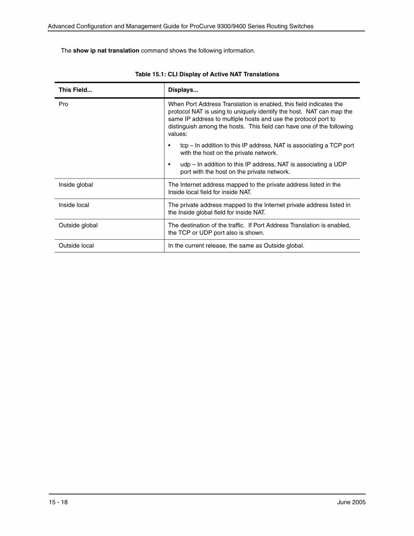
The show ip nat translation command shows the following information.
Table 15.1: CLI Display of Active NAT Translations
This Field...
Pro
Inside global
Inside local
Outside global
Outside local
Displays...
When Port Address Translation is enabled, this field indicates the protocol NAT is using to uniquely identify the host. NAT can map the same IP address to multiple hosts and use the protocol port to distinguish among the hosts. This field can have one of the following values:
• tcp – In addition to this IP address, NAT is associating a TCP port with the host on the private network.
• udp – In addition to this IP address, NAT is associating a UDP port with the host on the private network.
The Internet address mapped to the private address listed in the Inside local field for inside NAT.
The private address mapped to the Internet private address listed in the Inside global field for inside NAT.
The destination of the traffic. If Port Address Translation is enabled, the TCP or UDP port also is shown.
In the current release, the same as Outside global.
15 - 18 June 2005

Network Address Translation (9300 Series Only)
Displaying NAT Statistics To display NAT statistics, use the following CLI method.
USING THE CLI
To display the NAT statistics, enter the following command at any level of the CLI:
ProCurveRS(config)# show ip nat statistics
Total translations: 10 (0 static, 10 dynamic)Hits: 10 Misses: 1Expired translations: 1Dynamic mappings:pool rtrpool: mask = 255.255.255.255
start 192.168.2.79 end 192.168.2.79 total addresses 1 overloaded
IP Fragments: saved 0, restored 0, timed out 0Sess: Total 524288, Avail 524243, NAT 22
Inside global Last Inside Local xmit pkts xmit bytes rx pkts rx bytes cnt 192.168.2.79 10.10.100.18 62 4012 42 4285 10
Syntax: show ip nat statistics
The show ip nat statistics command shows the following information.
Table 15.2: CLI Display of NAT Statistics
This Field...
Total translations
Hits
Misses
Expired translations
Displays...
The number of translations that are currently active. This number changes when translations are added or age out. To display the currently active translations, enter the show ip nat translation command.
The number of times NAT searched the translation table for a NAT entry and found the needed entry. (To optimize performance, NAT looks in the NAT table for an existing entry for a given translation before creating an entry for that translation.)
The number of times NAT did not find a needed entry in the translation table. When this occurs, NAT creates the needed entry and places it in the table.
The total number of dynamic translations that have aged of the translation table since the HP device was booted.
June 2005 15 - 19
Advanced Configuration and Management Guide for ProCurve 9300/9400 Series Routing Switches
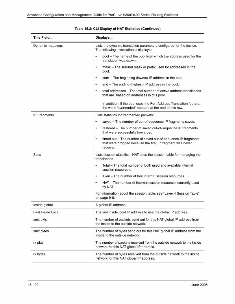
Table 15.2: CLI Display of NAT Statistics (Continued)
This Field...
Dynamic mappings
IP Fragments
Sess
Inside global
Last Inside Local
xmit pkts
xmit bytes
rx pkts
rx bytes
Displays...
Lists the dynamic translation parameters configured for the device. The following information is displayed:
• pool – The name of the pool from which the address used for the translation was drawn.
• mask – The sub-net mask or prefix used for addressed in the pool.
• start – The beginning (lowest) IP address in the pool.
• end – The ending (highest) IP address in the pool.
• total addresses – The total number of active address translations that are based on addresses in this pool.
In addition, if the pool uses the Port Address Translation feature, the word “overloaded” appears at the end of this row.
Lists statistics for fragmented packets:
• saved – The number of out-of-sequence IP fragments saved.
• restored – The number of saved out-of-sequence IP fragments that were successfully forwarded.
• timed out – The number of saved out-of-sequence IP fragments that were dropped because the first IP fragment was never received.
Lists session statistics. NAT uses the session table for managing the translations.
• Total – The total number of both used and available internal session resources.
• Avail – The number of free internal session resources.
• NAT – The number of internal session resources currently used by NAT.
For information about the session table, see “Layer 4 Session Table” on page 9-6.
A global IP address.
The last inside local IP address to use the global IP address.
The number of packets send out for this NAT global IP address from the inside to the outside network.
The number of bytes send out for this NAT global IP address from the inside to the outside network.
The number of packets received from the outside network to the inside network for this NAT global IP address.
The number of bytes received from the outside network to the inside network for this NAT global IP address.
15 - 20 June 2005
Network Address Translation (9300 Series Only)
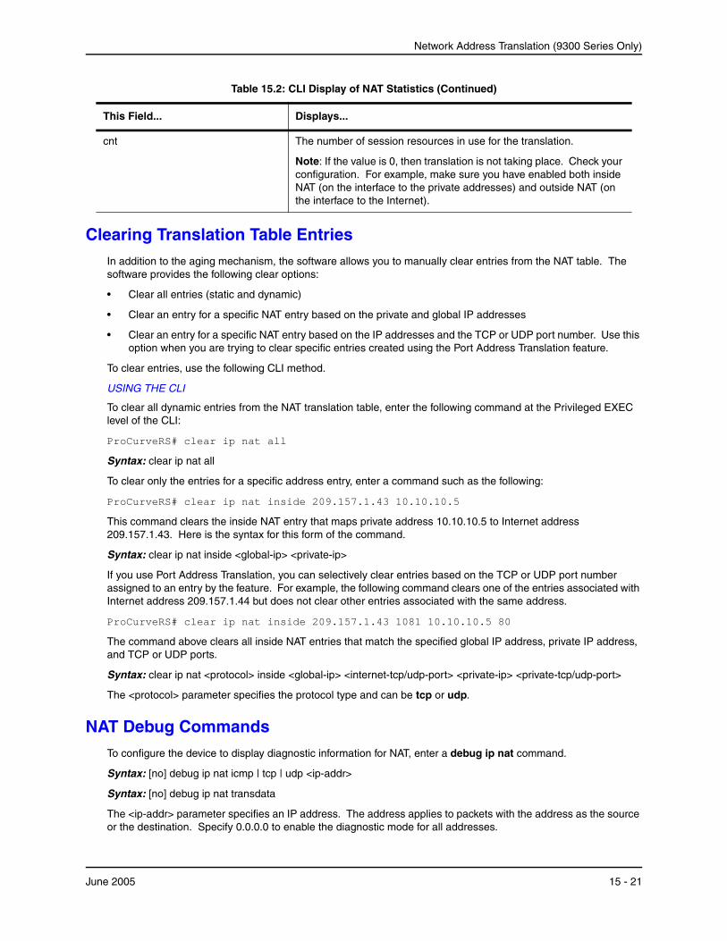
Table 15.2: CLI Display of NAT Statistics (Continued)
This Field... Displays...
cnt The number of session resources in use for the translation.
Note: If the value is 0, then translation is not taking place. Check your configuration. For example, make sure you have enabled both inside NAT (on the interface to the private addresses) and outside NAT (on the interface to the Internet).
Clearing Translation Table Entries In addition to the aging mechanism, the software allows you to manually clear entries from the NAT table. The software provides the following clear options:
• Clear all entries (static and dynamic)
• Clear an entry for a specific NAT entry based on the private and global IP addresses
• Clear an entry for a specific NAT entry based on the IP addresses and the TCP or UDP port number. Use this option when you are trying to clear specific entries created using the Port Address Translation feature.
To clear entries, use the following CLI method.
USING THE CLI
To clear all dynamic entries from the NAT translation table, enter the following command at the Privileged EXEC level of the CLI:
ProCurveRS# clear ip nat all
Syntax: clear ip nat all
To clear only the entries for a specific address entry, enter a command such as the following:
ProCurveRS# clear ip nat inside 209.157.1.43 10.10.10.5
This command clears the inside NAT entry that maps private address 10.10.10.5 to Internet address 209.157.1.43. Here is the syntax for this form of the command.
Syntax: clear ip nat inside <global-ip> <private-ip>
If you use Port Address Translation, you can selectively clear entries based on the TCP or UDP port number assigned to an entry by the feature. For example, the following command clears one of the entries associated with Internet address 209.157.1.44 but does not clear other entries associated with the same address.
ProCurveRS# clear ip nat inside 209.157.1.43 1081 10.10.10.5 80
The command above clears all inside NAT entries that match the specified global IP address, private IP address,and TCP or UDP ports.
Syntax: clear ip nat <protocol> inside <global-ip> <internet-tcp/udp-port> <private-ip> <private-tcp/udp-port>
The <protocol> parameter specifies the protocol type and can be tcp or udp.
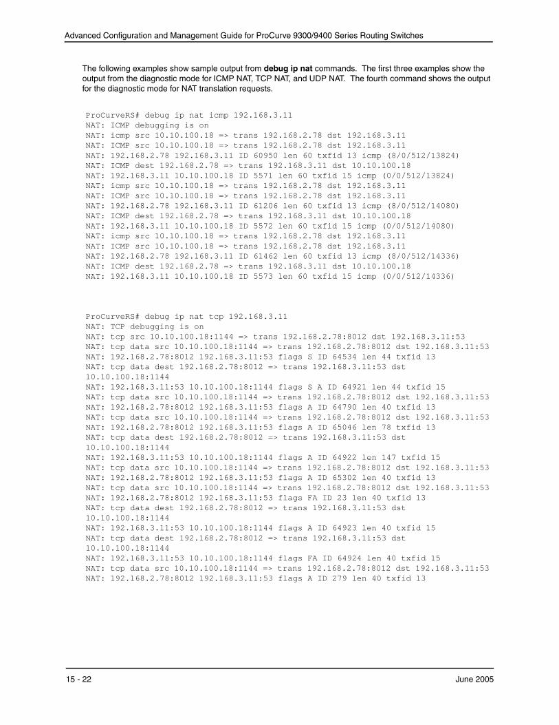
NAT Debug Commands To configure the device to display diagnostic information for NAT, enter a debug ip nat command.
Syntax: [no] debug ip nat icmp | tcp | udp <ip-addr>
Syntax: [no] debug ip nat transdata
The <ip-addr> parameter specifies an IP address. The address applies to packets with the address as the sourceor the destination. Specify 0.0.0.0 to enable the diagnostic mode for all addresses.
June 2005 15 - 21
Advanced Configuration and Management Guide for ProCurve 9300/9400 Series Routing Switches
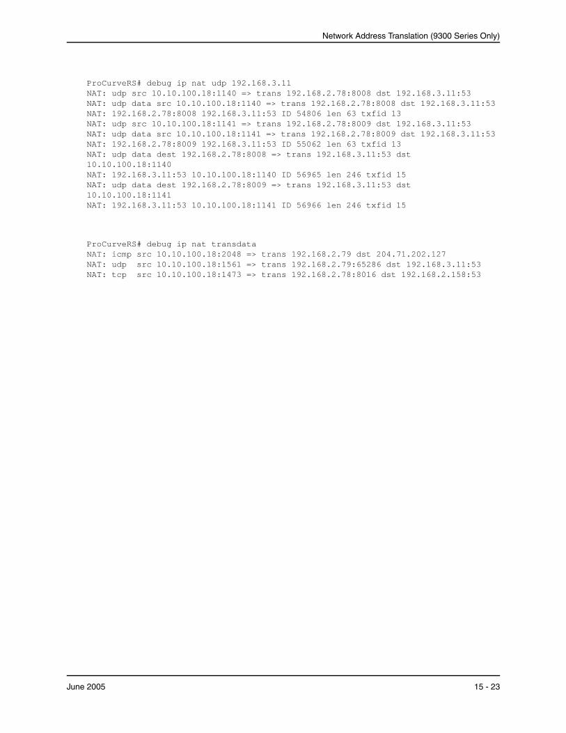
The following examples show sample output from debug ip nat commands. The first three examples show the output from the diagnostic mode for ICMP NAT, TCP NAT, and UDP NAT. The fourth command shows the output for the diagnostic mode for NAT translation requests.
ProCurveRS# debug ip nat icmp 192.168.3.11NAT: ICMP debugging is onNAT: icmp src 10.10.100.18 => trans 192.168.2.78 dst 192.168.3.11NAT: ICMP src 10.10.100.18 => trans 192.168.2.78 dst 192.168.3.11NAT: 192.168.2.78 192.168.3.11 ID 60950 len 60 txfid 13 icmp (8/0/512/13824)NAT: ICMP dest 192.168.2.78 => trans 192.168.3.11 dst 10.10.100.18NAT: 192.168.3.11 10.10.100.18 ID 5571 len 60 txfid 15 icmp (0/0/512/13824)NAT: icmp src 10.10.100.18 => trans 192.168.2.78 dst 192.168.3.11NAT: ICMP src 10.10.100.18 => trans 192.168.2.78 dst 192.168.3.11NAT: 192.168.2.78 192.168.3.11 ID 61206 len 60 txfid 13 icmp (8/0/512/14080)NAT: ICMP dest 192.168.2.78 => trans 192.168.3.11 dst 10.10.100.18NAT: 192.168.3.11 10.10.100.18 ID 5572 len 60 txfid 15 icmp (0/0/512/14080)NAT: icmp src 10.10.100.18 => trans 192.168.2.78 dst 192.168.3.11NAT: ICMP src 10.10.100.18 => trans 192.168.2.78 dst 192.168.3.11NAT: 192.168.2.78 192.168.3.11 ID 61462 len 60 txfid 13 icmp (8/0/512/14336)NAT: ICMP dest 192.168.2.78 => trans 192.168.3.11 dst 10.10.100.18NAT: 192.168.3.11 10.10.100.18 ID 5573 len 60 txfid 15 icmp (0/0/512/14336)
ProCurveRS# debug ip nat tcp 192.168.3.11 NAT: TCP debugging is on NAT: tcp src 10.10.100.18:1144 => trans 192.168.2.78:8012 dst 192.168.3.11:53 NAT: tcp data src 10.10.100.18:1144 => trans 192.168.2.78:8012 dst 192.168.3.11:53 NAT: 192.168.2.78:8012 192.168.3.11:53 flags S ID 64534 len 44 txfid 13 NAT: tcp data dest 192.168.2.78:8012 => trans 192.168.3.11:53 dst 10.10.100.18:1144 NAT: 192.168.3.11:53 10.10.100.18:1144 flags S A ID 64921 len 44 txfid 15 NAT: tcp data src 10.10.100.18:1144 => trans 192.168.2.78:8012 dst 192.168.3.11:53 NAT: 192.168.2.78:8012 192.168.3.11:53 flags A ID 64790 len 40 txfid 13 NAT: tcp data src 10.10.100.18:1144 => trans 192.168.2.78:8012 dst 192.168.3.11:53 NAT: 192.168.2.78:8012 192.168.3.11:53 flags A ID 65046 len 78 txfid 13 NAT: tcp data dest 192.168.2.78:8012 => trans 192.168.3.11:53 dst 10.10.100.18:1144 NAT: 192.168.3.11:53 10.10.100.18:1144 flags A ID 64922 len 147 txfid 15 NAT: tcp data src 10.10.100.18:1144 => trans 192.168.2.78:8012 dst 192.168.3.11:53 NAT: 192.168.2.78:8012 192.168.3.11:53 flags A ID 65302 len 40 txfid 13 NAT: tcp data src 10.10.100.18:1144 => trans 192.168.2.78:8012 dst 192.168.3.11:53 NAT: 192.168.2.78:8012 192.168.3.11:53 flags FA ID 23 len 40 txfid 13 NAT: tcp data dest 192.168.2.78:8012 => trans 192.168.3.11:53 dst 10.10.100.18:1144 NAT: 192.168.3.11:53 10.10.100.18:1144 flags A ID 64923 len 40 txfid 15 NAT: tcp data dest 192.168.2.78:8012 => trans 192.168.3.11:53 dst 10.10.100.18:1144 NAT: 192.168.3.11:53 10.10.100.18:1144 flags FA ID 64924 len 40 txfid 15 NAT: tcp data src 10.10.100.18:1144 => trans 192.168.2.78:8012 dst 192.168.3.11:53 NAT: 192.168.2.78:8012 192.168.3.11:53 flags A ID 279 len 40 txfid 13
15 - 22 June 2005
Network Address Translation (9300 Series Only)
ProCurveRS# debug ip nat udp 192.168.3.11 NAT: udp src 10.10.100.18:1140 => trans 192.168.2.78:8008 dst 192.168.3.11:53 NAT: udp data src 10.10.100.18:1140 => trans 192.168.2.78:8008 dst 192.168.3.11:53 NAT: 192.168.2.78:8008 192.168.3.11:53 ID 54806 len 63 txfid 13 NAT: udp src 10.10.100.18:1141 => trans 192.168.2.78:8009 dst 192.168.3.11:53 NAT: udp data src 10.10.100.18:1141 => trans 192.168.2.78:8009 dst 192.168.3.11:53 NAT: 192.168.2.78:8009 192.168.3.11:53 ID 55062 len 63 txfid 13 NAT: udp data dest 192.168.2.78:8008 => trans 192.168.3.11:53 dst 10.10.100.18:1140 NAT: 192.168.3.11:53 10.10.100.18:1140 ID 56965 len 246 txfid 15 NAT: udp data dest 192.168.2.78:8009 => trans 192.168.3.11:53 dst 10.10.100.18:1141 NAT: 192.168.3.11:53 10.10.100.18:1141 ID 56966 len 246 txfid 15
ProCurveRS# debug ip nat transdata NAT: icmp src 10.10.100.18:2048 => trans 192.168.2.79 dst 204.71.202.127 NAT: udp src 10.10.100.18:1561 => trans 192.168.2.79:65286 dst 192.168.3.11:53 NAT: tcp src 10.10.100.18:1473 => trans 192.168.2.78:8016 dst 192.168.2.158:53
June 2005 15 - 23

Advanced Configuration and Management Guide for ProCurve 9300/9400 Series Routing Switches
To disable the NAT diagnostic mode, enter a command such as the following:
ProCurveRS# no debug ip nat tcp
This command disables the diagnostic mode for NAT performed on TCP packets. NAT diagnostics for other types of packets remain enabled.
You also can use the following syntax to disable the diagnostic mode for NAT:
Syntax: undebug ip nat icmp | tcp | udp | transdata
15 - 24 June 2005