Embed Size (px)
Citation preview
1
Chapter 12Chapter 12Requirements to Requirements to Design Iteratively Design Iteratively
2
Iteratively:Iteratively: Do the Right Thing, Do the Right Thing, Do the Thing Right Do the Thing Right
• The requirements and Object-oriented analysis focus on to do the right thing– Understanding some of the outstanding goals, and related rules
and constraints.
• By contrast, design work stress to do the thing right– Skillfully designing a solution to satisfy the requirements for
this iteration.
• In iterative development– A transition from primarily requirements/analysis to primarily
design/implementation occurs in each iteration. – Early iterations will spend more time on analysis activities. – Later iterations it is common that analysis lessens; there's more
focus on just building the solution.
2
3
Provoking Early Change Provoking Early Change • Iterative and evolutionary methods “embrace change”
– It is natural to discover and change some requirements during the design and implementation work, especially in the early iterations.
• We try to provoke inevitable change in early iterations so that – We have a more stable goal (and estimate and schedule) for
the later iterations.– Early programming, tests, and demos help provoke the
inevitable changes early on.• Over the course of early elaboration iterations
– The requirements discovery should stabilize by the end of elaboration perhaps 80% of the requirements are reliablydefined (as a result of feedback)
• Rather than speculation, as occurs in a waterfall method
4
Didn't All That Analysis and Didn't All That Analysis and Modeling Take Weeks To Do Modeling Take Weeks To Do
• The duration to do all the actual modeling (use case writing, domain modeling..) that has been explored so far is realistically just a few hours or days.– When one is comfortable with the skills of use case writing,
domain modeling, etc.
• Many other activities of project planning, such as proof-of-concept programming, finding resources(people, software, …), planning, setting up the environment could consume a few weeks of preparation.
3
Chapter 13Chapter 13Logical Logical
Architecture and Architecture and UML Package UML Package
Diagrams Diagrams
6
IntroductionIntroduction• The design of a OO system is based on
several architectural layers– UI layer– Application logic (domain) layer– …
• This chapter explores a logical layered architecture and related UML notation
4
7
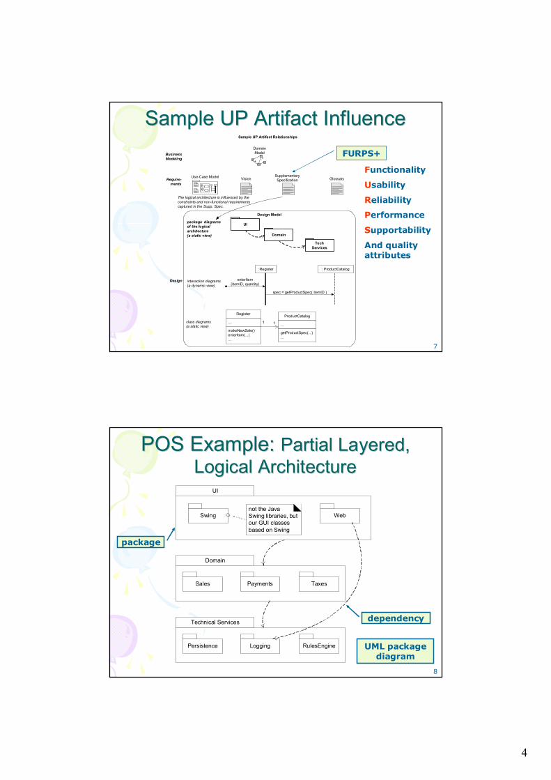
Sample UP Artifact Influence Sample UP Artifact Influence
: Register
enterItem(itemID, quantity)
: ProductCatalog
spec = getProductSpec( itemID )
Require-ments
Business Modeling
Design
Sample UP Artifact Relationships
Vision Glossary
The logical architecture is influenced by the constraints and non-functional requirements captured in the Supp. Spec.
Domain Model
**
SupplementarySpecification
Use-Case Model
Register
...
makeNewSale()enterItem(...)...
ProductCatalog
...
getProductSpec(...)...
1 1class diagrams(a static view)
interaction diagrams(a dynamic view)
UIpackage diagramsof the logical architecture(a static view) Domain
Tech Services
Design Model
FURPS+
Functionality
Usability
Reliability
Performance
Supportability
And quality attributes
8
POS Example: POS Example: Partial Layered, Partial Layered, Logical ArchitectureLogical Architecture
Domain
UI
Swingnot the Java Swing libraries, but our GUI classes based on Swing
Web
Sales Payments Taxes
Technical Services
Persistence Logging RulesEngine UML package diagram
dependency
package
5
9
What is the Logical Architecture? What is the Logical Architecture? And Layers? And Layers? 11
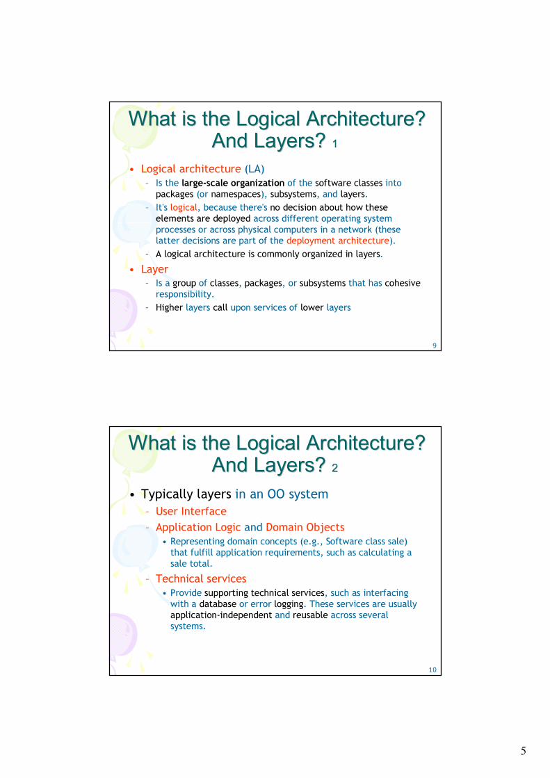
• Logical architecture (LA)– Is the large-scale organization of the software classes into
packages (or namespaces), subsystems, and layers. – It's logical, because there's no decision about how these
elements are deployed across different operating system processes or across physical computers in a network (these latter decisions are part of the deployment architecture).
– A logical architecture is commonly organized in layers.
• Layer– Is a group of classes, packages, or subsystems that has cohesive
responsibility.– Higher layers call upon services of lower layers
10
What is the Logical Architecture? What is the Logical Architecture? And Layers? And Layers? 22
• Typically layers in an OO system– User Interface– Application Logic and Domain Objects
• Representing domain concepts (e.g., Software class sale) that fulfill application requirements, such as calculating a sale total.
– Technical services• Provide supporting technical services, such as interfacing
with a database or error logging. These services are usually application-independent and reusable across several systems.
6
11
What is the Logical Architecture? What is the Logical Architecture? And Layers And Layers 33
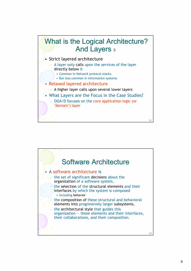
• Strict layered architecture– A layer only calls upon the services of the layer
directly below it• Common in Network protocol stacks.• But less common in information systems
• Relaxed layered architecture– A higher layer calls upon several lower layers
• What Layers are the Focus in the Case Studies? – OOA/D focuses on the core application logic (or
"domain") layer
12
Software Architecture Software Architecture • A software architecture is
– the set of significant decisions about the organization of a software system,
– the selection of the structural elements and their interfaces by which the system is composed
• Including behavior
– the composition of these structural and behavioral elements into progressively larger subsystems,
– the architectural style that guides this organization — these elements and their interfaces, their collaborations, and their composition.
7
13
Applying UML: Package Applying UML: Package Diagrams Diagrams 11
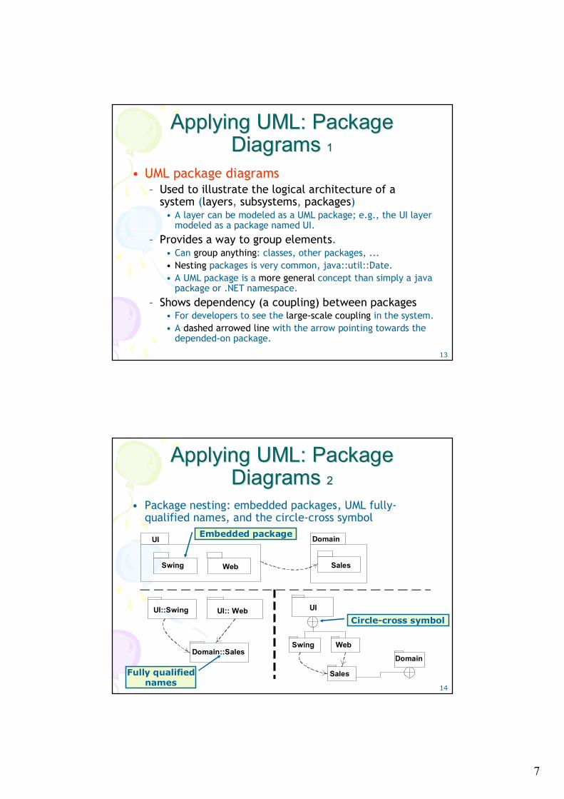
• UML package diagrams– Used to illustrate the logical architecture of a
system (layers, subsystems, packages) • A layer can be modeled as a UML package; e.g., the UI layer
modeled as a package named UI.
– Provides a way to group elements. • Can group anything: classes, other packages, ...• Nesting packages is very common, java::util::Date. • A UML package is a more general concept than simply a java
package or .NET namespace.
– Shows dependency (a coupling) between packages• For developers to see the large-scale coupling in the system. • A dashed arrowed line with the arrow pointing towards the
depended-on package.
14
Applying UML: Package Applying UML: Package Diagrams Diagrams 22
• Package nesting: embedded packages, UML fully-qualified names, and the circle-cross symbol
Domain::Sales
UI:: WebUI::Swing
Sales
WebSwing
UI
Domain
DomainUI
Swing SalesWeb
Fully qualified names
Embedded package
Circle-cross symbol
8
15
Guideline: Design with LayersGuideline: Design with Layers11
• The essential ideas of using layers – Organize the large-scale logical structure of a
system into discrete layers of distinct, related responsibilities, with a clean, cohesive separation of concerns
• The higher layers are more application specific• The lower layers are low-level and general services
– Collaboration and coupling is from higher to lower layers; lower-to-higher layer coupling is avoided.
See next page
16
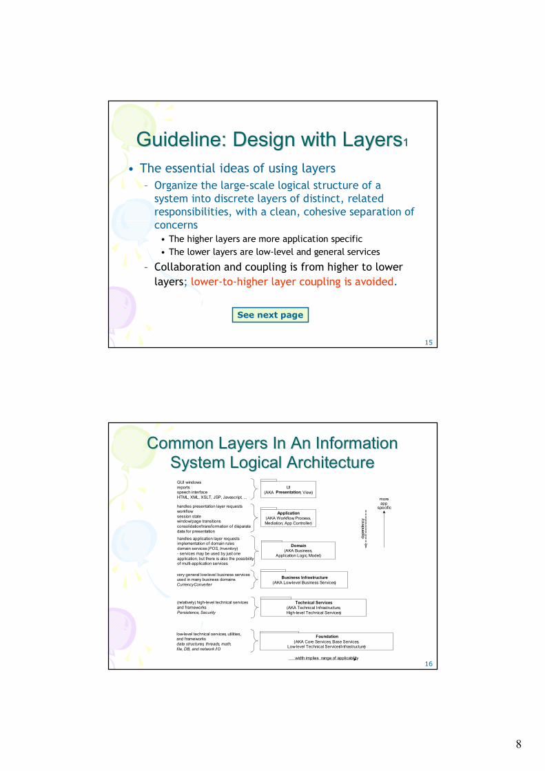
Common Layers In An Information Common Layers In An Information System Logical ArchitectureSystem Logical Architecture
UI(AKA Presentation, View)
Application(AKA Workflow, Process,Mediation, App Controller)
Domain(AKA Business,
Application Logic, Model)
Technical Services(AKA Technical Infrastructure, High-level Technical Services)
Foundation(AKA Core Services, Base Services,
Low-level Technical Services/ Infrastructure)
width implies range of applicability
GUI windowsreportsspeech interfaceHTML, XML, XSLT, JSP, Javascript, ...
handles presentation layer requestsworkflowsession statewindow/page transitionsconsolidation/transformation of disparate data for presentation
handles application layer requestsimplementation of domain rulesdomain services (POS, Inventory)- services may be used by just one application, but there is also the possibility of multi-application services
(relatively) high-level technical services and frameworks Persistence, Security
low-level technical services, utilities, and frameworksdata structures, threads, math, file, DB, and network I/ O
moreapp
specific
d epe
nde n
cy
Business Infrastructure(AKA Low-level Business Services)
very general low-level business services used in many business domainsCurrencyConverter
9
17
Guideline: Design with LayersGuideline: Design with Layers22
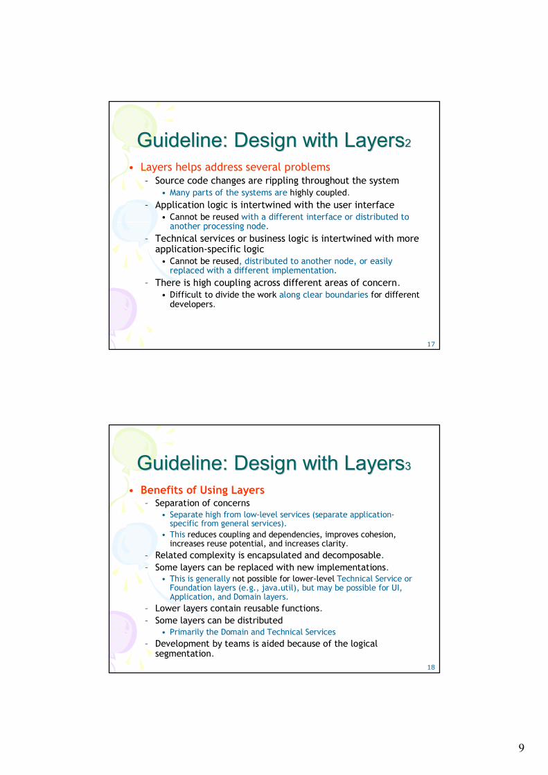
• Layers helps address several problems– Source code changes are rippling throughout the system
• Many parts of the systems are highly coupled.– Application logic is intertwined with the user interface
• Cannot be reused with a different interface or distributed to another processing node.
– Technical services or business logic is intertwined with more application-specific logic
• Cannot be reused, distributed to another node, or easily replaced with a different implementation.
– There is high coupling across different areas of concern.• Difficult to divide the work along clear boundaries for different
developers.
18
Guideline: Design with LayersGuideline: Design with Layers33
• Benefits of Using Layers– Separation of concerns
• Separate high from low-level services (separate application-specific from general services).
• This reduces coupling and dependencies, improves cohesion, increases reuse potential, and increases clarity.
– Related complexity is encapsulated and decomposable.– Some layers can be replaced with new implementations.
• This is generally not possible for lower-level Technical Service or Foundation layers (e.g., java.util), but may be possible for UI, Application, and Domain layers.
– Lower layers contain reusable functions.– Some layers can be distributed
• Primarily the Domain and Technical Services– Development by teams is aided because of the logical
segmentation.
10
19
Guideline: Cohesive Responsibilities; Guideline: Cohesive Responsibilities; Maintain a Separation of ConcernsMaintain a Separation of Concerns
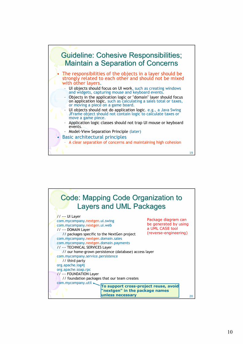
• The responsibilities of the objects in a layer should be strongly related to each other and should not be mixed with other layers. – UI objects should focus on UI work, such as creating windows
and widgets, capturing mouse and keyboard events.– Objects in the application logic or "domain" layer should focus
on application logic, such as calculating a sales total or taxes, or moving a piece on a game board.
– UI objects should not do application logic. e.g., a Java Swing JFrame object should not contain logic to calculate taxes or move a game piece.
– Application logic classes should not trap UI mouse or keyboard events.
– Model-View Separation Principle (later)• Basic architectural principles
– A clear separation of concerns and maintaining high cohesion
20
Code: Mapping Code Organization to Code: Mapping Code Organization to Layers and UML PackagesLayers and UML Packages
// --- UI Layer com.mycompany.nextgen.ui.swing com.mycompany.nextgen.ui.web // --- DOMAIN Layer
// packages specific to the NextGen projectcom.mycompany.nextgen.domain.sales com.mycompany.nextgen.domain.payments // --- TECHNICAL SERVICES Layer
// our home-grown persistence (database) access layercom.mycompany.service.persistence
// third party org.apache.log4j org.apache.soap.rpc // --- FOUNDATION Layer
// foundation packages that our team creates com.mycompany.util
Package diagram can be generated by using a UML CASE tool (reverse-engineering)
To support cross-project reuse, avoid "nextgen" in the package names unless necessary
11
21
Domain Layer vs. Application Logic Domain Layer vs. Application Logic Layer; Domain ObjectsLayer; Domain Objects
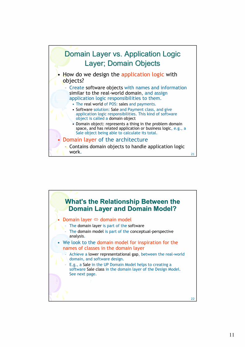
• How do we design the application logic with objects?– Create software objects with names and information
similar to the real-world domain, and assign application logic responsibilities to them.
• The real world of POS: sales and payments. • Software solution: Sale and Payment class, and give
application logic responsibilities. This kind of software object is called a domain object
• Domain object: represents a thing in the problem domain space, and has related application or business logic, e.g., a Sale object being able to calculate its total.
• Domain layer of the architecture– Contains domain objects to handle application logic
work.
22
What's the Relationship Between the What's the Relationship Between the Domain Layer and Domain Model?Domain Layer and Domain Model?
• Domain layer domain model– The domain layer is part of the software– The domain model is part of the conceptual-perspective
analysis.
• We look to the domain model for inspiration for the names of classes in the domain layer– Achieve a lower representational gap, between the real-world
domain, and software design. – E.g., a Sale in the UP Domain Model helps to creating a
software Sale class in the domain layer of the Design Model. See next page.
12
23
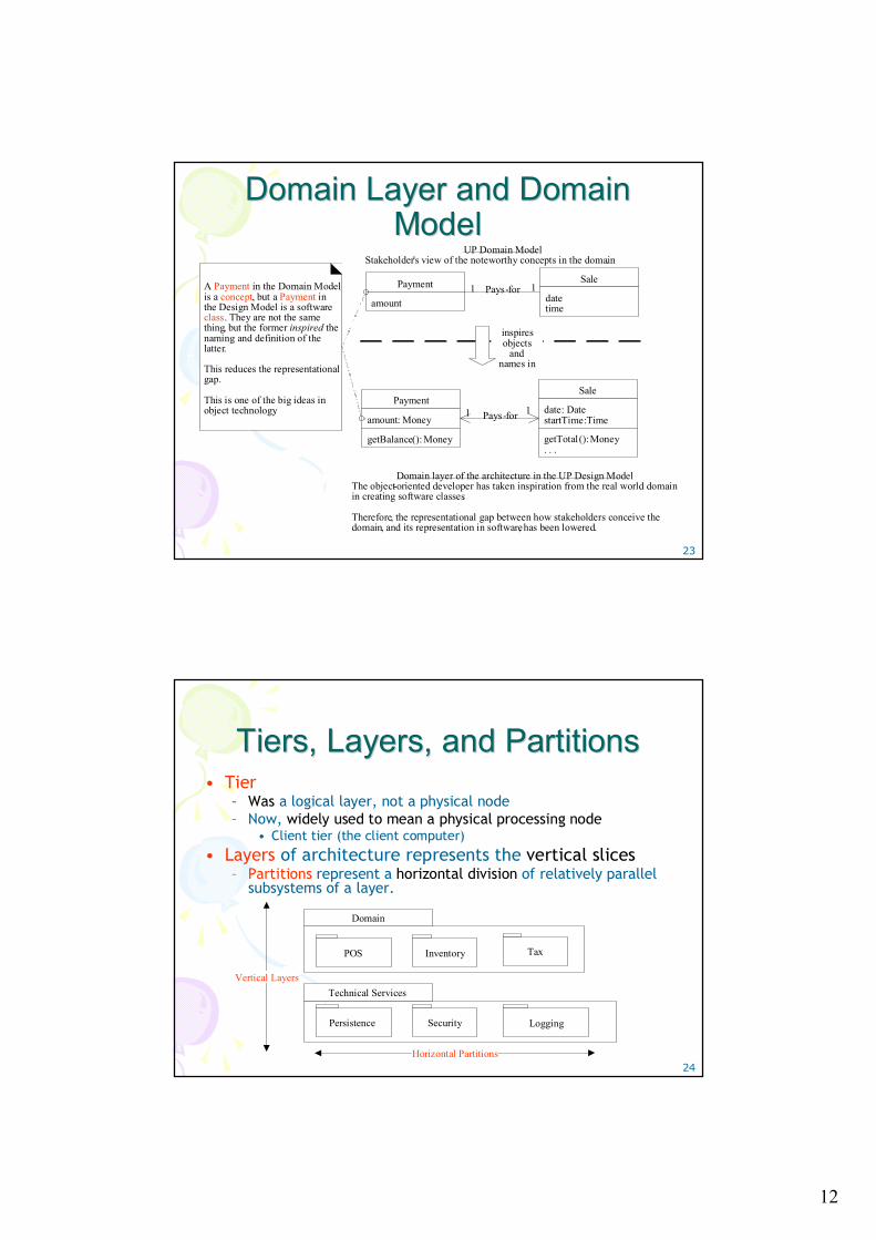
Domain Layer and Domain Domain Layer and Domain ModelModelPayment
amount
Sale
datetime
Pays-for
Payment
amount: Money
getBalance(): Money
Sale
date: DatestartTime: Time
getTotal(): Money. . .
Pays-for
UP Domain ModelStakeholder's view of the noteworthy concepts in the domain.
Domain layer of the architecture in the UP Design ModelThe object-oriented developer has taken inspiration from the real world domain in creating software classes.
Therefore, the representational gap between how stakeholders conceive the domain, and its representation in software, has been lowered.
1 1
1 1
A Payment in the Domain Model is a concept, but a Payment in the Design Model is a software class. They are not the same thing, but the former inspired the naming and definition of the latter.
This reduces the representational gap.
This is one of the big ideas in object technology.
inspires objects
and names in
24
Tiers, Layers, and Partitions Tiers, Layers, and Partitions • Tier
– Was a logical layer, not a physical node– Now, widely used to mean a physical processing node
• Client tier (the client computer)
• Layers of architecture represents the vertical slices– Partitions represent a horizontal division of relatively parallel
subsystems of a layer.
Persistence Security Logging
Technical Services
POS Inventory Tax
Domain
Vertical Layers
Horizontal Partitions
13
25
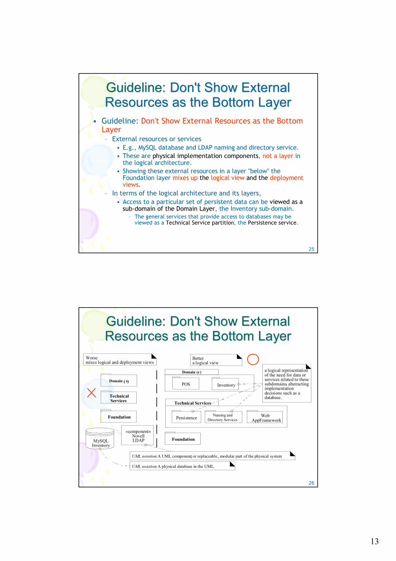
Guideline:Guideline: Don't Show External Don't Show External Resources as the Bottom LayerResources as the Bottom Layer
• Guideline: Don't Show External Resources as the Bottom Layer– External resources or services
• E.g., MySQL database and LDAP naming and directory service. • These are physical implementation components, not a layer in
the logical architecture.• Showing these external resources in a layer "below" the
Foundation layer mixes up the logical view and the deployment views.
– In terms of the logical architecture and its layers, • Access to a particular set of persistent data can be viewed as a
sub-domain of the Domain Layer, the Inventory sub-domain. – The general services that provide access to databases may be
viewed as a Technical Service partition, the Persistence service.
26
Guideline:Guideline: Don't Show External Don't Show External Resources as the Bottom LayerResources as the Bottom Layer
Domain ( s)
Technical Services
Foundation
MySQLInventory
Persistence Naming andDirectory Services
Web AppFramework
Technical Services
POS Inventory
Domain (s )
Foundation
Worsemixes logical and deployment views
Bettera logical view
a logical representation of the need for data or services related to these subdomains, abstracting implementation decisions such as a database.
«component»NovellLDAP
UML notation: A UML component, or replaceable , modular part of the physical system
UML notation: A physical database in the UML.
14
27
Guideline:Guideline: ModelModel--View Separation View Separation Principle Principle 11
• Guideline: Model-view separation principle– Model is a synonym for the domain layer of objects.– View is a synonym for UI objects.– Do not connect or couple model objects directly to view
objects (model objects should not have direct knowledge of view objects)
• A sale object should not directly send a message to a GUI windowobject processsaleframe, asking it to display something, change color, close,...; don't let a sale object have a reference to a swing Jframe window object.
• Why? The windows are related to a particular application, while the non-windowing objects may be reused in new applications or attached to a new interface.
– Do not put application logic (such as a tax calculation) in the UI object methods.
• UI objects should only initialize UI elements, receive UI events, and delegate requests for application logic on to domain objects.
28
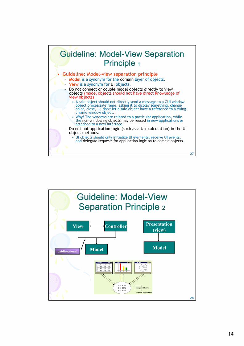
Guideline:Guideline: ModelModel--View View Separation Principle Separation Principle 22
a
b
ca b c
a = 50%b = 30%c = 20%
change notification
requests, modifications
xyz
a b c
305080
2010
1010
3060
unidirectional
View Controller
Model Model
Presentation(view)
15
29
Guideline:Guideline: ModelModel--View Separation View Separation Principle Principle 22
• Model-view-controller (MVC) pattern.– Data objects (models), GUI widgets (views), and mouse and
keyboard event handlers (controllers).– "MVC" has been applied on a large-scale architectural level. The
model is the domain layer, the view is the UI layer, and the controllers are the workflow objects in the application layer.
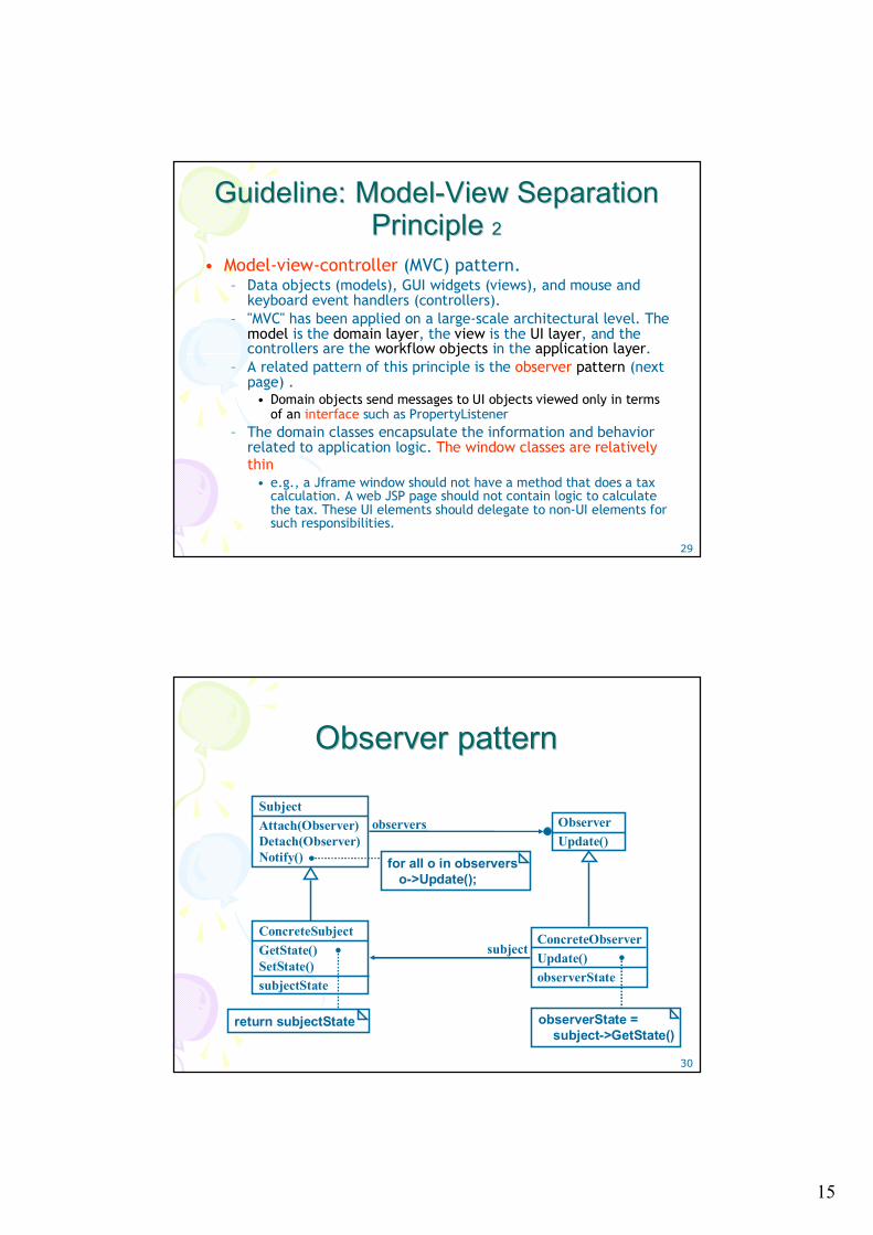
– A related pattern of this principle is the observer pattern (next page) .
• Domain objects send messages to UI objects viewed only in terms of an interface such as PropertyListener
– The domain classes encapsulate the information and behavior related to application logic. The window classes are relatively thin
• e.g., a Jframe window should not have a method that does a tax calculation. A web JSP page should not contain logic to calculate the tax. These UI elements should delegate to non-UI elements for such responsibilities.
30
Observer patternObserver pattern
SubjectAttach(Observer)Detach(Observer)Notify()
ConcreteSubjectGetState()SetState()subjectState
ObserverUpdate()
ConcreteObserverUpdate()observerState
observerState = subject->GetState()
return subjectState
observers
subject
for all o in observerso->Update();
16
31
Guideline:Guideline: ModelModel--View Separation View Separation Principle Principle 33
• The motivation for Model-View Separation– To support cohesive model definitions that focus on the
domain processes, rather than on user interfaces.– To allow separate development of the model and user
interface layers.– To minimize the impact of requirements changes in the
interface upon the domain layer.– To allow new views to be easily connected to an existing
domain layer, without affecting the domain layer.– To allow multiple simultaneous views on the same model
object, such as both a tabular and business chart view of sales information.
– To allow execution of the model layer independent of the user interface layer, such as a message-processing or batch-mode system.
– To allow easy porting of the model layer to another user interface framework.
32
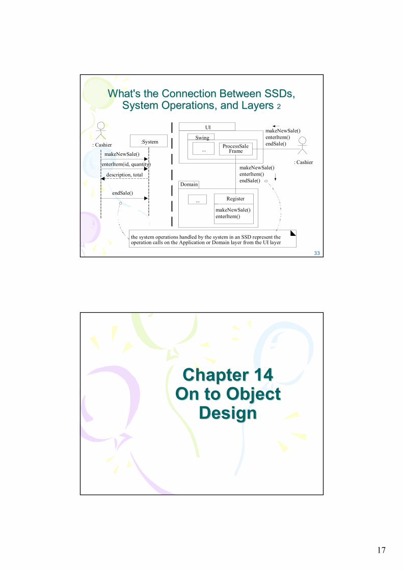
What's the Connection Between What's the Connection Between SSDsSSDs, , System Operations, and Layers System Operations, and Layers 11
• The SSDs illustrate system operations, hide UI objects.– The UI layer objects capture system operation requests,
e.g., makeNewSale and enterItem.– The UI layer objects forward or delegate the request from
the UI layer onto the domain layer for handling.– The messages sent from the UI layer to the domain layer
will be the messages illustrated on the SSDs, such as enterItem.
– e.g., Java Swing/GUI window class called ProcessSaleFrame in the UI layer picks up the mouse and keyboard events requesting to enter an item, and then the ProcessSaleFrame object will send an enterItem message on to a software object in the domain layer, such as Register, to perform the application logic.
17
33
What's the Connection Between What's the Connection Between SSDsSSDs, , System Operations, and Layers System Operations, and Layers 22
Domain
UI
SwingProcessSale
Frame...
... Register
makeNewSale()enterItem()
: Cashier
makeNewSale()enterItem()endSale()
enterItem(id, quantity))
:System: Cashier
endSale()
description, total
makeNewSale()
the system operations handled by the system in an SSD represent the operation calls on the Application or Domain layer from the UI layer
makeNewSale()enterItem()endSale()
Chapter 14Chapter 14On to Object On to Object
DesignDesign
18
35
Three Ways to Develop Three Ways to Develop ProgramsPrograms
• How do developers design objects? – Code. Design-while-coding (Java, C#, …), ideally with power
tools such as refactorings. From mental model to code.– Draw, then code. Drawing some UML on a whiteboard or UML
CASE tool, then switching to #1 with a text-strong IDE (e.g., Eclipse or Visual Studio).
– Only draw. Somehow, the tool generates everything from diagrams. • "Only draw" is a misnomer, as this still involves a text
programming language attached to UML graphic elements.
• This chapter introduces object design and lightweight drawing before coding, suggesting ways to make it pay off.
36
Agile Modeling and Lightweight Agile Modeling and Lightweight UML Drawing UML Drawing
• Aims of agile modeling– Reduce drawing overhead– Model to understand and communicate– Rather than to document
• Practices– Using lots of whiteboards (ten in a room, not two) covering
large wall areas, using markers, digital cameras, and printers to capture "UML as sketch"
• Agile modeling also includes– Modeling with others– Creating several models in parallel. (later)
19
37
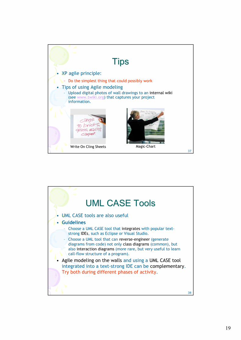
TipsTips• XP agile principle:
– Do the simplest thing that could possibly work
• Tips of using Agile modeling– Upload digital photos of wall drawings to an internal wiki
(see www.twiki.org) that captures your project information.
Magic-ChartWrite On Cling Sheets
38
UML CASE ToolsUML CASE Tools• UML CASE tools are also useful• Guidelines
– Choose a UML CASE tool that integrates with popular text-strong IDEs, such as Eclipse or Visual Studio.
– Choose a UML tool that can reverse-engineer (generate diagrams from code) not only class diagrams (common), but also interaction diagrams (more rare, but very useful to learn call-flow structure of a program).
• Agile modeling on the walls and using a UML CASE toolintegrated into a text-strong IDE can be complementary. Try both during different phases of activity.

20
39
How Much Time Spent Drawing How Much Time Spent Drawing UML Before Coding UML Before Coding
• For a three-week timeboxed iteration, – Spend a few hours or at most one day (with
partners) near the start of the iteration "at the walls" (or with a UML CASE tool)
– Then stop - and if sketching - perhaps take digital photos, print the pictures, and transition to coding for the remainder of the iteration
– Using the UML drawings for inspiration as a starting point, but recognizing that the final design in code will diverge and improve.
– Shorter drawing/sketching sessions may occur throughout the iteration.
40
Designing Objects Designing Objects 11
• Dynamic models static models – Dynamic models
• such as UML interaction diagrams (sequence diagrams or communication diagrams), help design the logic, the behavior of the code or the method bodies.
– Static models• such as UML class diagrams, package diagrams and
deployment diagrams ; help design the definition of packages, class names, attributes, and method signatures(but not method bodies).
• Agile modeling practice of create models in parallel – Spend a short period of time on interaction diagrams
(dynamics), then switch to a wall of related class diagrams (statics).

21
41
Designing Objects Designing Objects 22
42
Dynamic Object ModelingDynamic Object Modeling• Dynamic Object modeling
– Most of the challenging, interesting, useful design workhappens while drawing the UML dynamic-view interaction diagrams
– During dynamic object modeling (such as drawing sequence diagrams), we start thinking through the exact details of what objects need to exist and how they collaborate via messages and methods
• Guideline– Spend significant time doing interaction diagrams (sequence or
communication diagrams), not just class diagrams.– Ignoring this guideline is a very common worst-practice with
UML.• Note
– During dynamic modeling, we apply responsibility-driven design(RDD) and the GRASP principles

22
43
Object Design Skill Object Design Skill • The importance of object design skill is over UML
notation skill– What's important is knowing how to think and design in
objects, and apply object design best-practice patterns, which is much more valuable skill than knowing UML notation
– Drawing UML is a reflection of making decisions about the design.
• While drawing a UML object diagram, we need to answer key questions: – What are the responsibilities of the object?– Who does it collaborate with?– What design patterns should be applied?– Far more important than knowing the difference between
UML 1.4 and 2.0 notation!
44
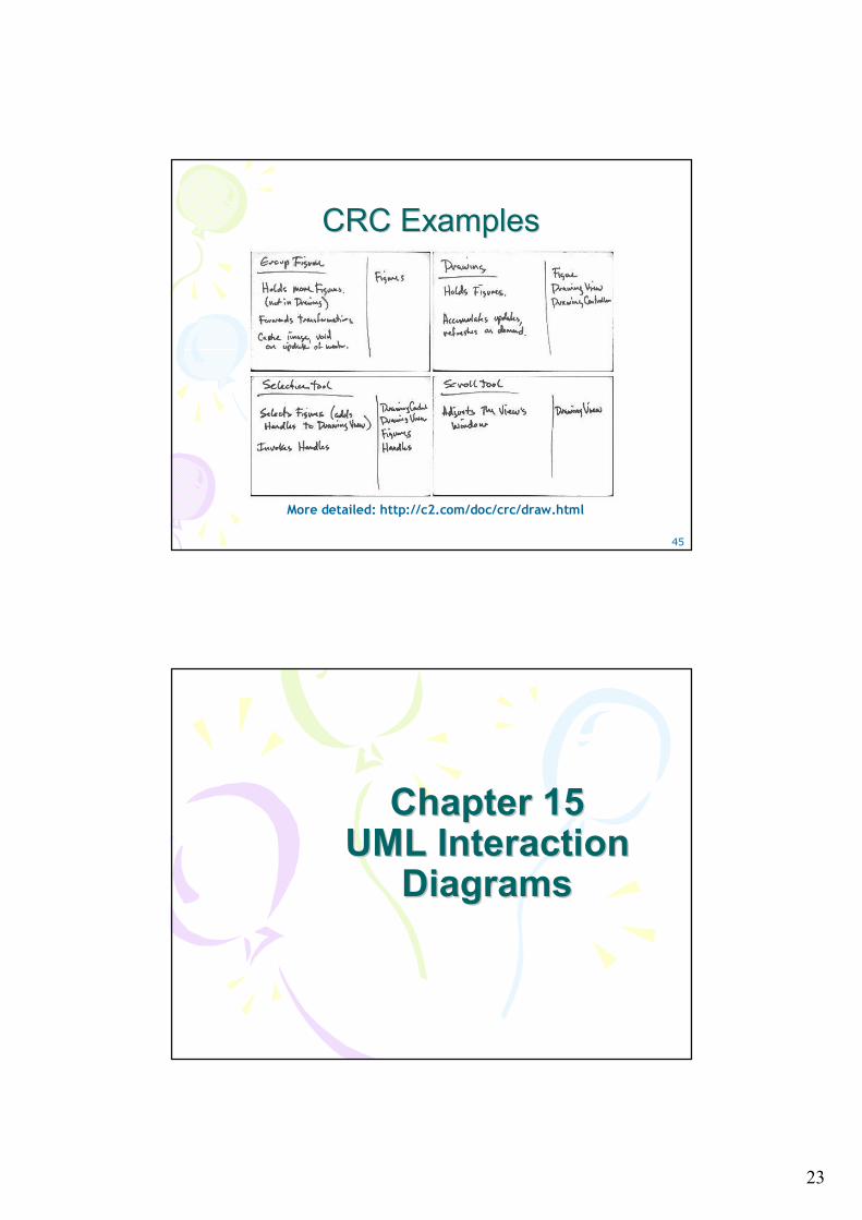
Class Responsibility CardClass Responsibility Card• A popular text-oriented
modeling technique is Class Responsibility Collaboration (CRC) cards
• CRC cards are paper index cards on which one writes the responsibilities and collaborators of classes
• A CRC modeling session involves a group sitting around a table, discussing and writing on the cards as they play "what if" scenarios with the objects, considering what they must do and what other objects they must collaborate with.
Each card represents one class
23
45
CRC ExamplesCRC Examples
More detailed: http://c2.com/doc/crc/draw.html
Chapter 15Chapter 15UML Interaction UML Interaction
Diagrams Diagrams
24
47
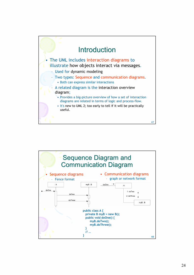
IntroductionIntroduction• The UML includes interaction diagrams to
illustrate how objects interact via messages. – Used for dynamic modeling– Two types: Sequence and communication diagrams.
• Both can express similar interactions
– A related diagram is the interaction overview diagram;
• Provides a big-picture overview of how a set of interaction diagrams are related in terms of logic and process-flow.
• It's new to UML 2; too early to tell if it will be practically useful.
48
Sequence Diagram and Sequence Diagram and Communication DiagramCommunication Diagram
• Sequence diagrams– Fence format
public class A {private B myB = new B(); public void doOne() {
myB.doTwo(); myB.doThree();
} // …
}
• Communication diagrams– graph or network format
25
49
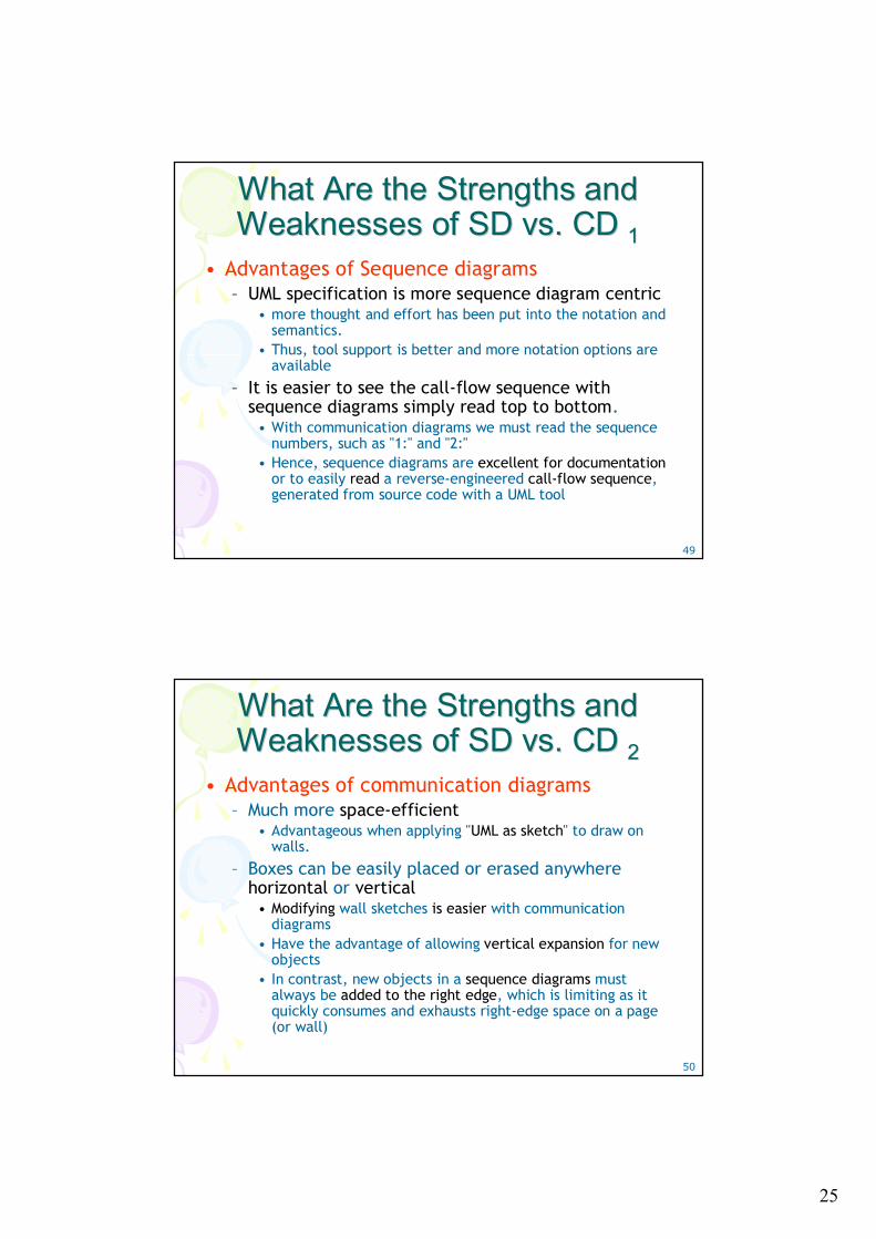
What Are the Strengths and What Are the Strengths and Weaknesses of SD vs. CD Weaknesses of SD vs. CD 11
• Advantages of Sequence diagrams– UML specification is more sequence diagram centric
• more thought and effort has been put into the notation and semantics.
• Thus, tool support is better and more notation options are available
– It is easier to see the call-flow sequence with sequence diagrams simply read top to bottom.
• With communication diagrams we must read the sequence numbers, such as "1:" and "2:"
• Hence, sequence diagrams are excellent for documentationor to easily read a reverse-engineered call-flow sequence, generated from source code with a UML tool
50
What Are the Strengths and What Are the Strengths and Weaknesses of SD vs. CD Weaknesses of SD vs. CD 22
• Advantages of communication diagrams– Much more space-efficient
• Advantageous when applying "UML as sketch" to draw on walls.
– Boxes can be easily placed or erased anywhere horizontal or vertical
• Modifying wall sketches is easier with communication diagrams
• Have the advantage of allowing vertical expansion for new objects
• In contrast, new objects in a sequence diagrams must always be added to the right edge, which is limiting as it quickly consumes and exhausts right-edge space on a page (or wall)
26
51
What Are the Strengths and What Are the Strengths and Weaknesses of SD vs. CD Weaknesses of SD vs. CD 33
52
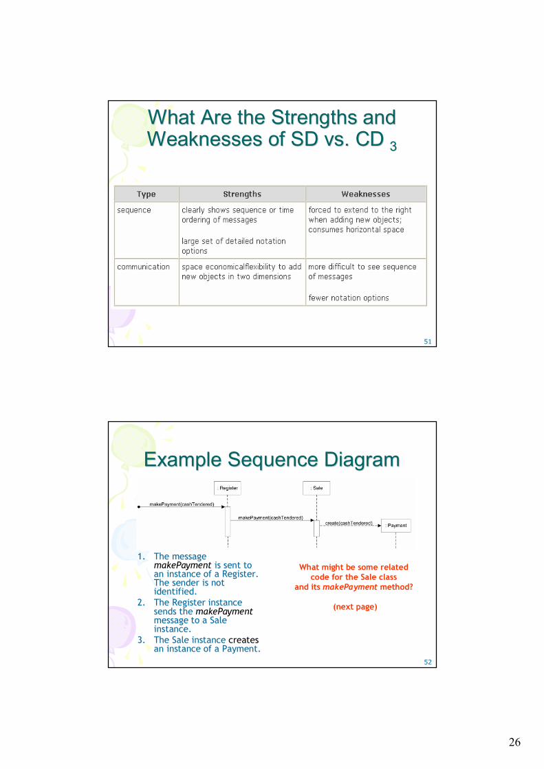
Example Sequence DiagramExample Sequence Diagram
1. The message makePayment is sent to an instance of a Register. The sender is not identified.
2. The Register instance sends the makePaymentmessage to a Sale instance.
3. The Sale instance createsan instance of a Payment.
What might be some related code for the Sale class
and its makePayment method?
(next page)
27
53
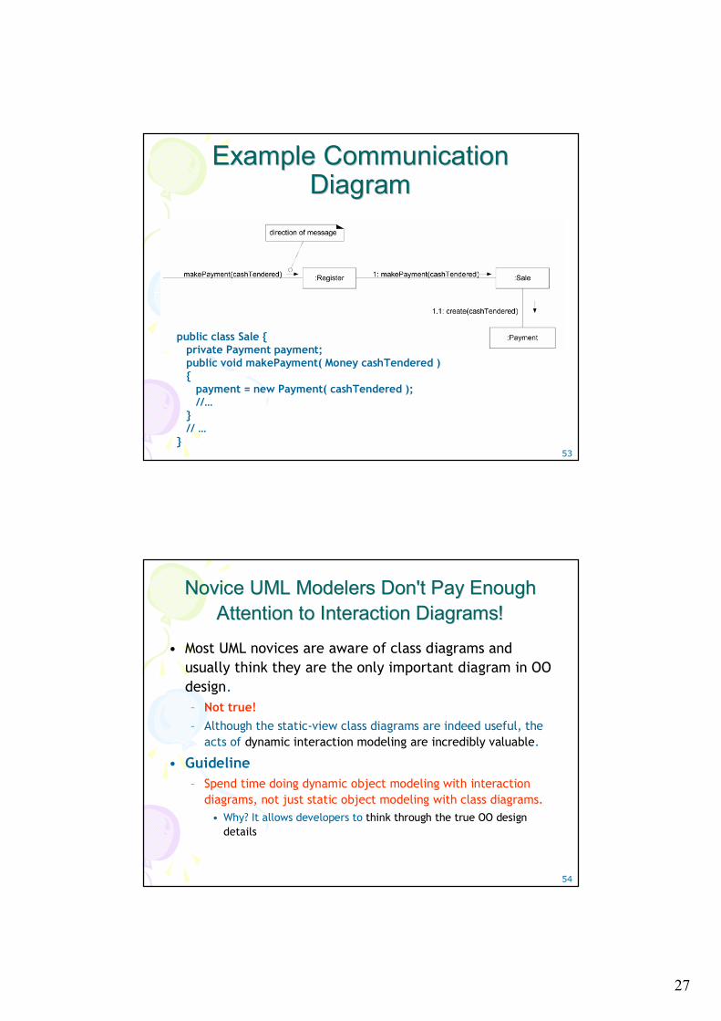
Example Communication Example Communication Diagram Diagram
public class Sale { private Payment payment; public void makePayment( Money cashTendered ){
payment = new Payment( cashTendered ); //…
} // …
}
54
Novice UML Modelers Don't Pay Enough Novice UML Modelers Don't Pay Enough Attention to Interaction Diagrams!Attention to Interaction Diagrams!
• Most UML novices are aware of class diagrams and usually think they are the only important diagram in OO design. – Not true!– Although the static-view class diagrams are indeed useful, the
acts of dynamic interaction modeling are incredibly valuable.
• Guideline– Spend time doing dynamic object modeling with interaction
diagrams, not just static object modeling with class diagrams. • Why? It allows developers to think through the true OO design
details
28
55
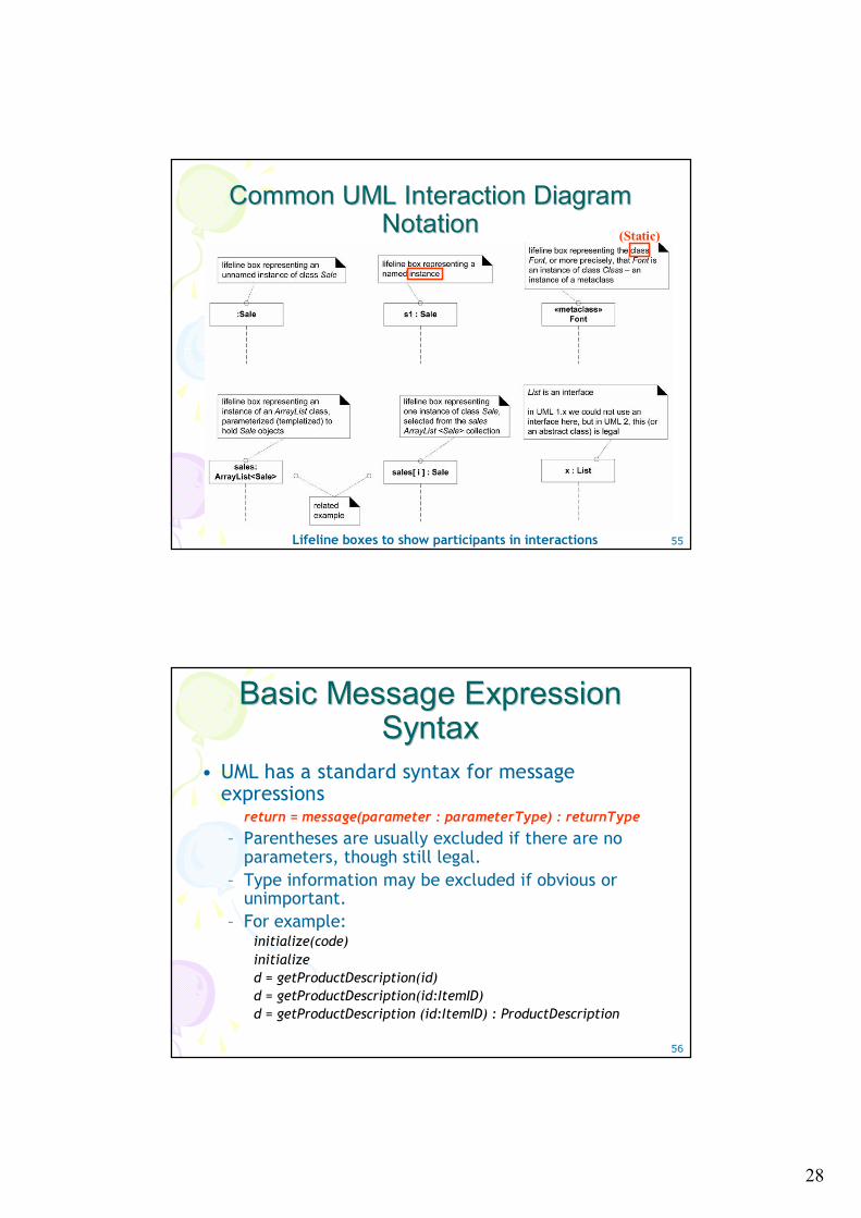
Common UML Interaction Diagram Common UML Interaction Diagram Notation Notation
Lifeline boxes to show participants in interactions
(Static)
56
Basic Message Expression Basic Message Expression Syntax Syntax
• UML has a standard syntax for message expressions
return = message(parameter : parameterType) : returnType
– Parentheses are usually excluded if there are no parameters, though still legal.
– Type information may be excluded if obvious or unimportant.
– For example:initialize(code) initialize d = getProductDescription(id) d = getProductDescription(id:ItemID) d = getProductDescription (id:ItemID) : ProductDescription
29
57
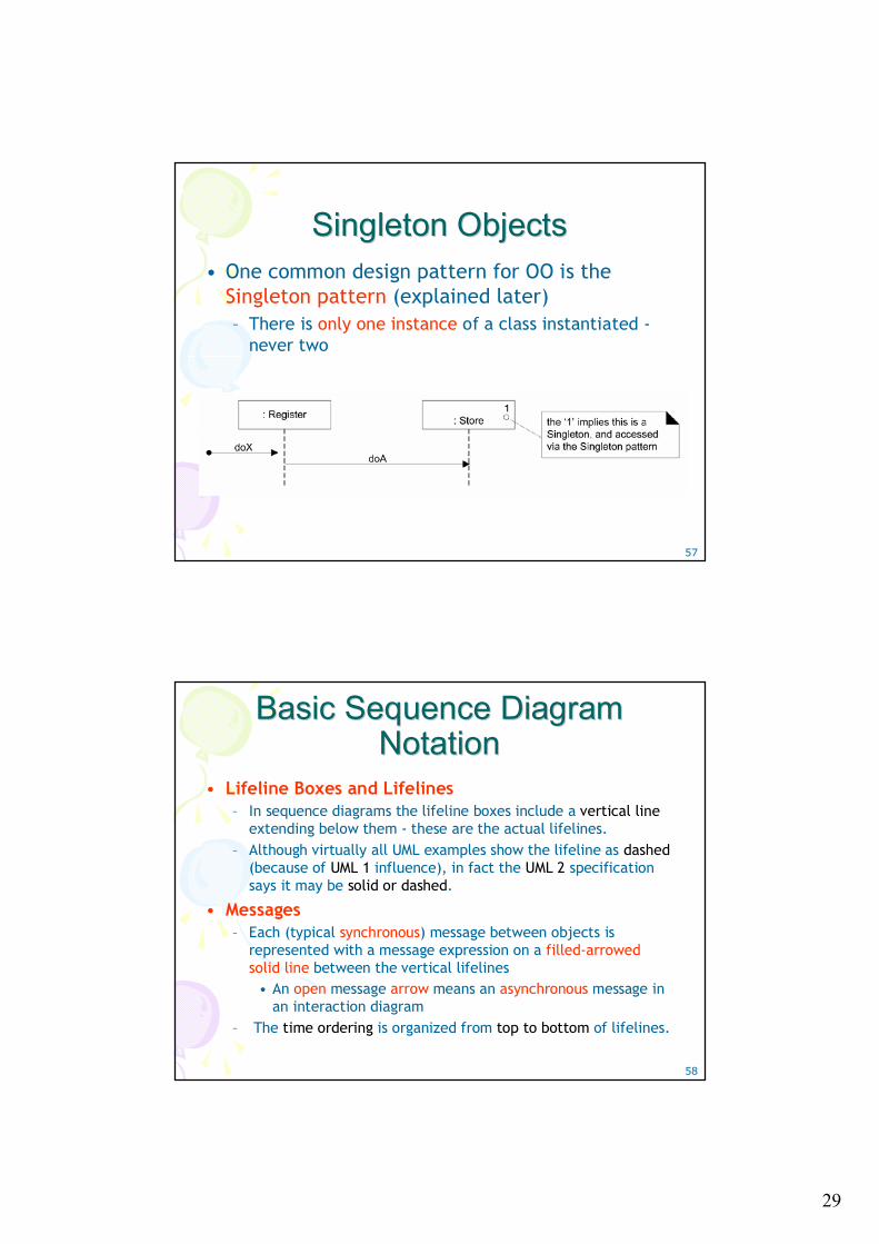
Singleton Objects Singleton Objects • One common design pattern for OO is the
Singleton pattern (explained later)– There is only one instance of a class instantiated -
never two
58
Basic Sequence Diagram Basic Sequence Diagram Notation Notation
• Lifeline Boxes and Lifelines– In sequence diagrams the lifeline boxes include a vertical line
extending below them - these are the actual lifelines.– Although virtually all UML examples show the lifeline as dashed
(because of UML 1 influence), in fact the UML 2 specification says it may be solid or dashed.
• Messages– Each (typical synchronous) message between objects is
represented with a message expression on a filled-arrowed solid line between the vertical lifelines
• An open message arrow means an asynchronous message in an interaction diagram
– The time ordering is organized from top to bottom of lifelines.
30
59
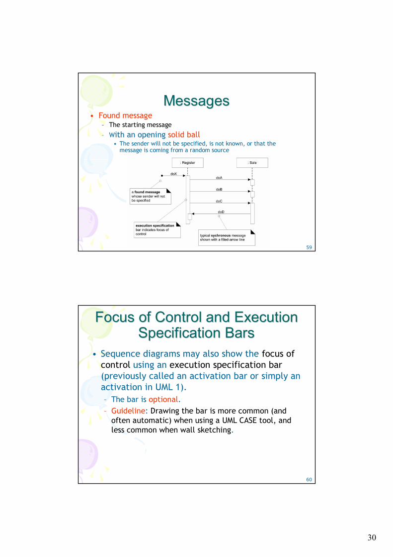
MessagesMessages• Found message
– The starting message
– With an opening solid ball• The sender will not be specified, is not known, or that the
message is coming from a random source
60
Focus of Control and Execution Focus of Control and Execution Specification Bars Specification Bars
• Sequence diagrams may also show the focus of control using an execution specification bar(previously called an activation bar or simply an activation in UML 1). – The bar is optional.– Guideline: Drawing the bar is more common (and
often automatic) when using a UML CASE tool, and less common when wall sketching.
31
61
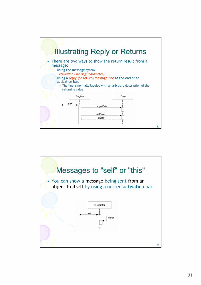
Illustrating Reply or Returns Illustrating Reply or Returns • There are two ways to show the return result from a
message:– Using the message syntax
returnVar = message(parameter).– Using a reply (or return) message line at the end of an
activation bar.• The line is normally labeled with an arbitrary description of the
returning value
62
Messages to "self" or "this" Messages to "self" or "this" • You can show a message being sent from an
object to itself by using a nested activation bar
32
63
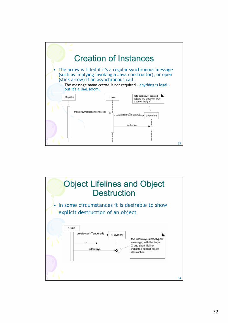
Creation of InstancesCreation of Instances• The arrow is filled if it's a regular synchronous message
(such as implying invoking a Java constructor), or open (stick arrow) if an asynchronous call. – The message name create is not required - anything is legal -
but it's a UML idiom.
: Register : Sale
makePayment(cashTendered): Paymentcreate(cashTendered)
authorize
note that newly created objects are placed at their creation "height"
64
Object Lifelines and Object Object Lifelines and Object DestructionDestruction
• In some circumstances it is desirable to show explicit destruction of an object
33
65
Diagram Frames in UML Sequence Diagram Frames in UML Sequence Diagrams Diagrams 11
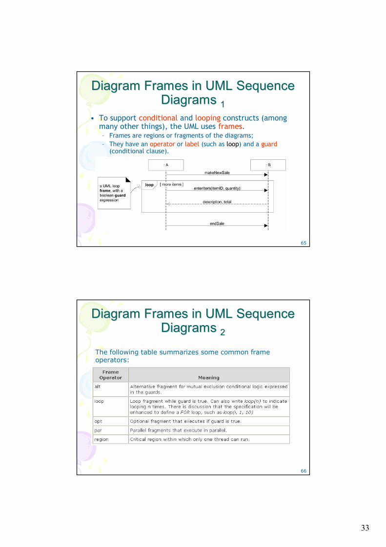
• To support conditional and looping constructs (among many other things), the UML uses frames.– Frames are regions or fragments of the diagrams; – They have an operator or label (such as loop) and a guard
(conditional clause).
66
Diagram Frames in UML Sequence Diagram Frames in UML Sequence Diagrams Diagrams 22
The following table summarizes some common frame operators:
34
67
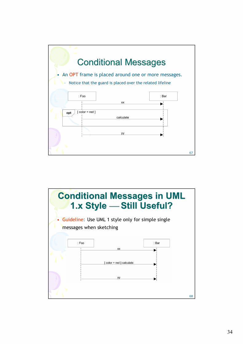
Conditional Messages Conditional Messages • An OPT frame is placed around one or more messages.
– Notice that the guard is placed over the related lifeline
calculate
: Bar
yy
xx
[ color = red ]opt
: Foo
68
Conditional Messages in UML Conditional Messages in UML 1.x Style 1.x Style ⎯⎯ Still Useful?Still Useful?
• Guideline: Use UML 1 style only for simple single
messages when sketching
35
69
Mutually Exclusive Conditional Mutually Exclusive Conditional MessagesMessages
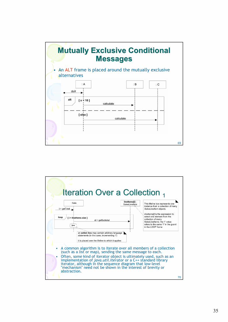
• An ALT frame is placed around the mutually exclusive alternatives
70
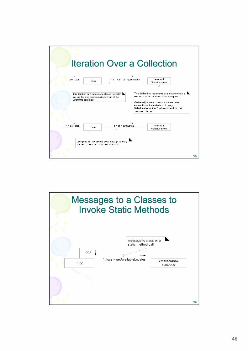
Iteration Over a Collection Iteration Over a Collection 11
• A common algorithm is to iterate over all members of a collection (such as a list or map), sending the same message to each.
• Often, some kind of iterator object is ultimately used, such as an implementation of java.util.Iterator or a C++ standard library iterator, although in the sequence diagram that low-level "mechanism" need not be shown in the interest of brevity or abstraction.
36
71
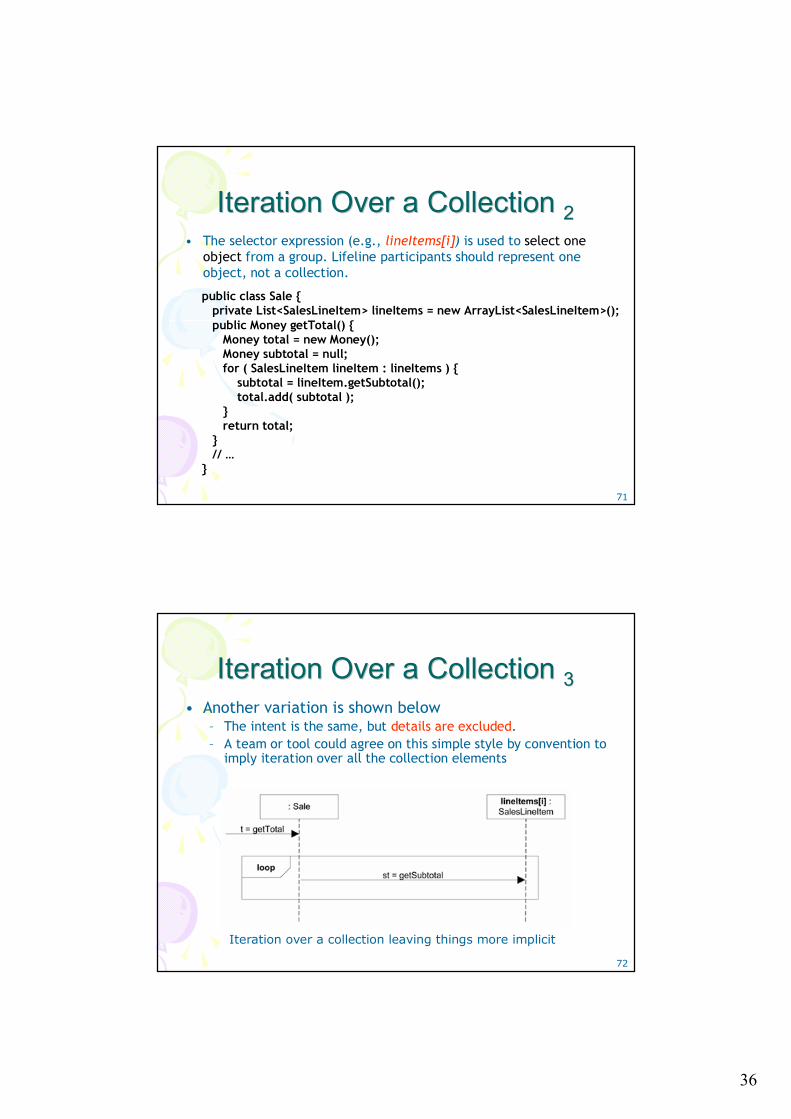
Iteration Over a Collection Iteration Over a Collection 22• The selector expression (e.g., lineItems[i]) is used to select one
object from a group. Lifeline participants should represent one object, not a collection.
public class Sale { private List<SalesLineItem> lineItems = new ArrayList<SalesLineItem>(); public Money getTotal() {
Money total = new Money(); Money subtotal = null; for ( SalesLineItem lineItem : lineItems ) {
subtotal = lineItem.getSubtotal(); total.add( subtotal );
} return total;
} // …
}
72
Iteration Over a Collection Iteration Over a Collection 33• Another variation is shown below
– The intent is the same, but details are excluded. – A team or tool could agree on this simple style by convention to
imply iteration over all the collection elements
Iteration over a collection leaving things more implicit
37
73
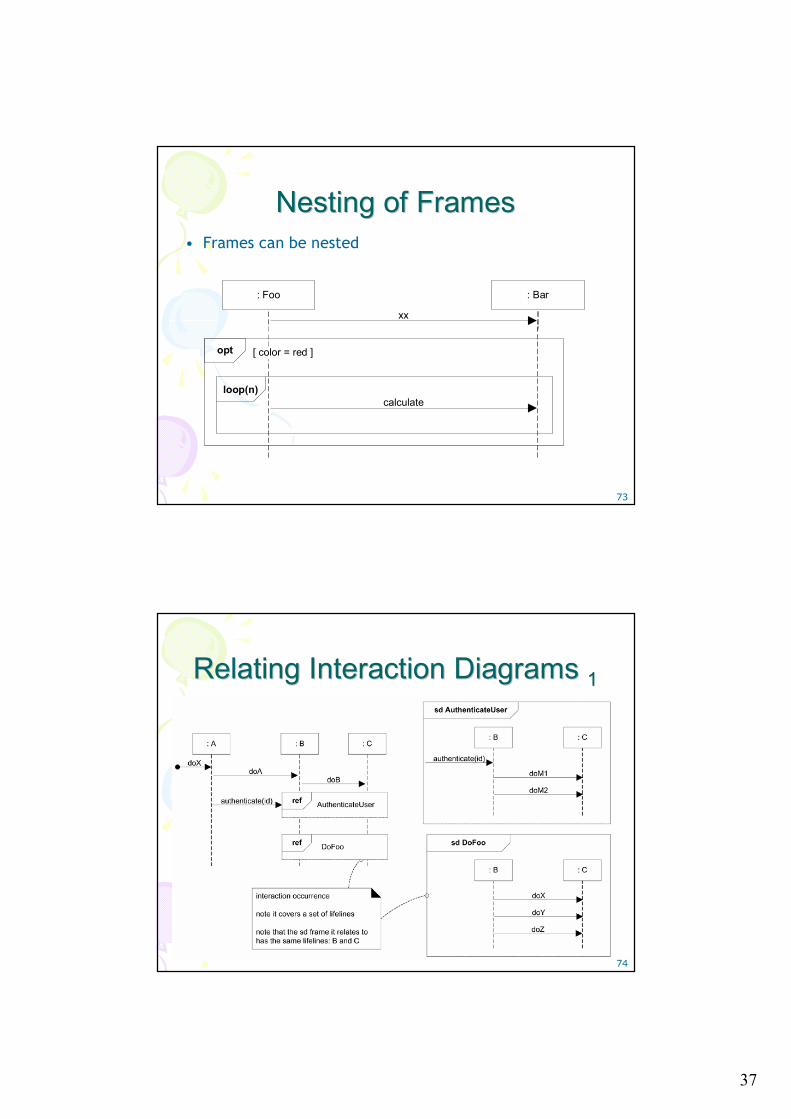
Nesting of Frames Nesting of Frames • Frames can be nested
calculate
: Bar
xx
[ color = red ]opt
: Foo
loop(n)
74
Relating Interaction Diagrams Relating Interaction Diagrams 11
38
75
Relating Interaction Diagrams Relating Interaction Diagrams 22• An interaction occurrence (also called an interaction use) is a
reference to an interaction within another interaction.– For example, when you want to simplify a diagram and factor out a
portion into another diagram, or there is a reusable interaction occurrence.
– UML tools take advantage of them, because of their usefulness inrelating and linking diagrams.
• They are created with two related frames:– A frame around an entire sequence diagram, labeled with the tag sd
and a name, such as AuthenticateUser– A frame tagged ref, called a reference, that refers to another named
sequence diagram; it is the actual interaction occurrence• Guideline: Any sequence diagram can be surrounded with an sd
frame, to name it. Frame and name one when you want to refer to it using a ref frame.
76
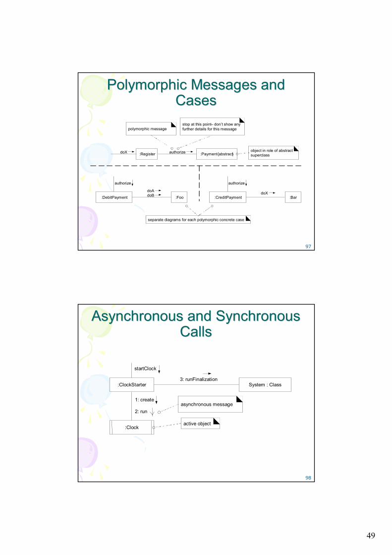
Messages to Classes to Invoke Messages to Classes to Invoke Static (or Class) Methods Static (or Class) Methods 11
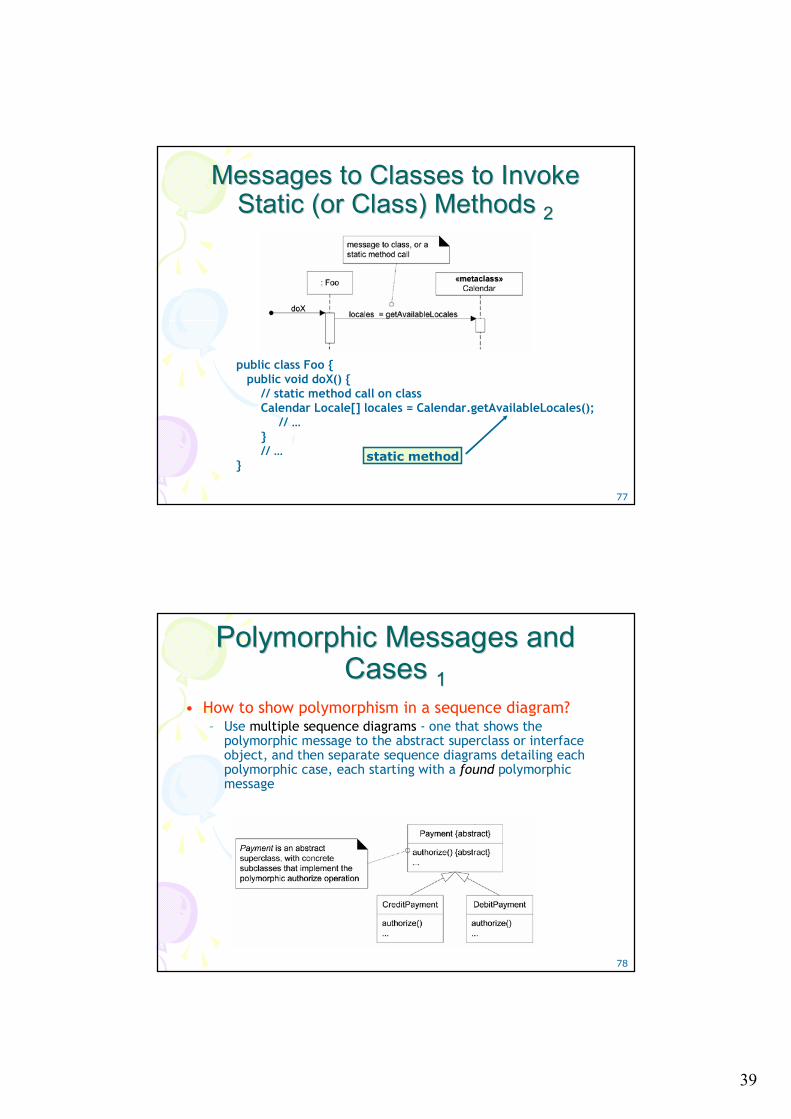
• You can show class or static method calls by using a lifeline box label that indicates the receiving object is a class, or more precisely, an instance of a metaclass– A metaclass is a class whose instances are classes
• In Java and Smalltalk, all classes are conceptually or literallyinstances of class Class;
• In .NET classes are instances of class Type.
• The classes Class and Type are metaclasses, which means their instances are themselves classes.
– A specific class, such as class Calendar, is itself an instance of class Class. Thus, class Calendar is an instance of a metaclass!
39
77
Messages to Classes to Invoke Messages to Classes to Invoke Static (or Class) Methods Static (or Class) Methods 22
public class Foo { public void doX() {
// static method call on class Calendar Locale[] locales = Calendar.getAvailableLocales();
// …} // …
}static method
78
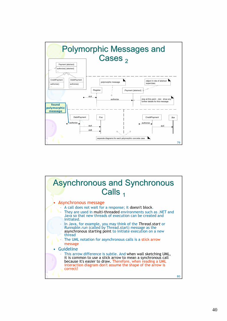
Polymorphic Messages and Polymorphic Messages and Cases Cases 11
• How to show polymorphism in a sequence diagram?– Use multiple sequence diagrams - one that shows the
polymorphic message to the abstract superclass or interface object, and then separate sequence diagrams detailing each polymorphic case, each starting with a found polymorphic message
40
79
Polymorphic Messages and Polymorphic Messages and Cases Cases 22
found polymorphic
message
:Register
authorizedoX
:Payment {abstract}
polymorphic message object in role of abstract superclass
:DebitPayment
doAauthorize
:Foo
stop at this point – don show any further details for this message
doB
:CreditPayment
doXauthorize
:Bar
separate diagrams for each polymorphic concrete case
Payment {abstract}
authorize() {abstract}...
CreditPayment
authorize()...
DebitPayment
authorize()...
80
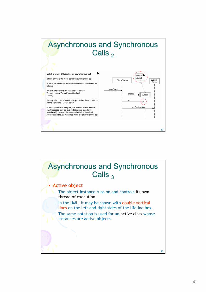
Asynchronous and Synchronous Asynchronous and Synchronous Calls Calls 11
• Asynchronous message– A call does not wait for a response; it doesn't block. – They are used in multi-threaded environments such as .NET and
Java so that new threads of execution can be created and initiated.
– In Java, for example, you may think of the Thread.start or Runnable.run (called by Thread.start) message as the asynchronous starting point to initiate execution on a new thread
– The UML notation for asynchronous calls is a stick arrow message
• Guideline– This arrow difference is subtle. And when wall sketching UML,
it is common to use a stick arrow to mean a synchronous call because it's easier to draw. Therefore, when reading a UML interaction diagram don't assume the shape of the arrow is correct!
41
81
Asynchronous and Synchronous Asynchronous and Synchronous Calls Calls 22
82
Asynchronous and Synchronous Asynchronous and Synchronous Calls Calls 33
• Active object– The object instance runs on and controls its own
thread of execution. – In the UML, it may be shown with double vertical
lines on the left and right sides of the lifeline box. – The same notation is used for an active class whose
instances are active objects.
42
83
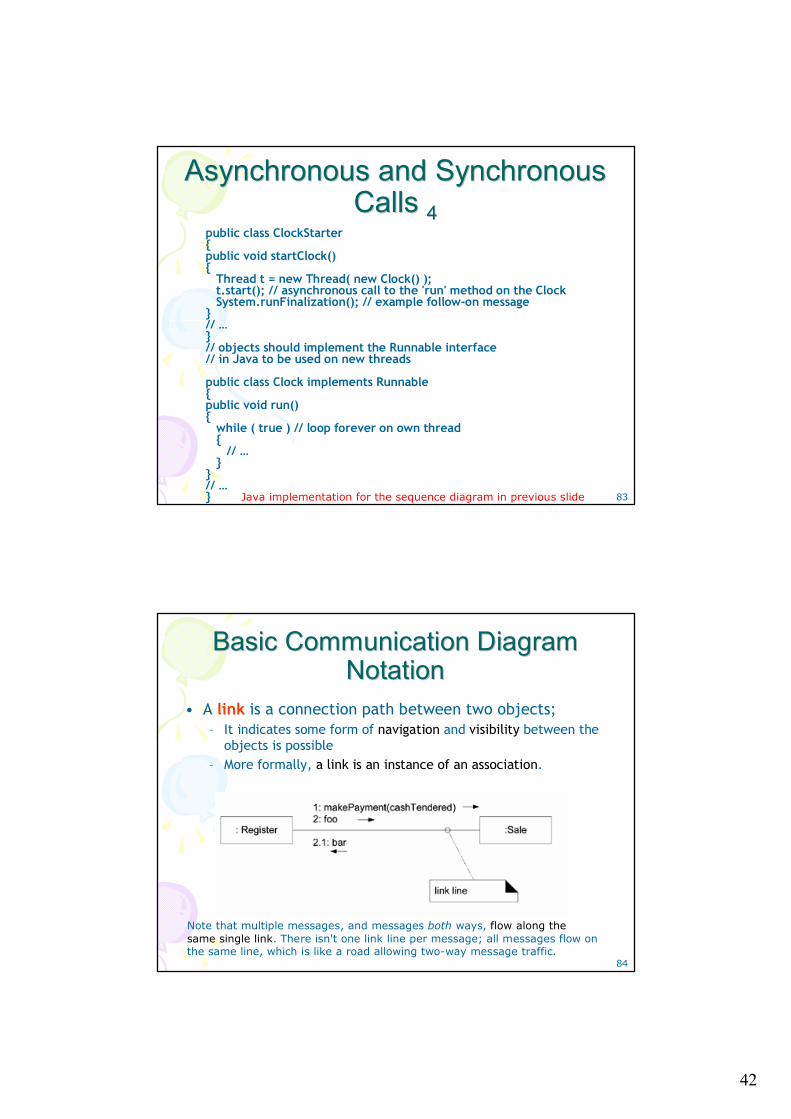
Asynchronous and Synchronous Asynchronous and Synchronous Calls Calls 44
public class ClockStarter{public void startClock(){
Thread t = new Thread( new Clock() );t.start(); // asynchronous call to the 'run' method on the ClockSystem.runFinalization(); // example follow-on message
}// …}// objects should implement the Runnable interface// in Java to be used on new threads
public class Clock implements Runnable{public void run(){
while ( true ) // loop forever on own thread{
// …}
}// …} Java implementation for the sequence diagram in previous slide
84
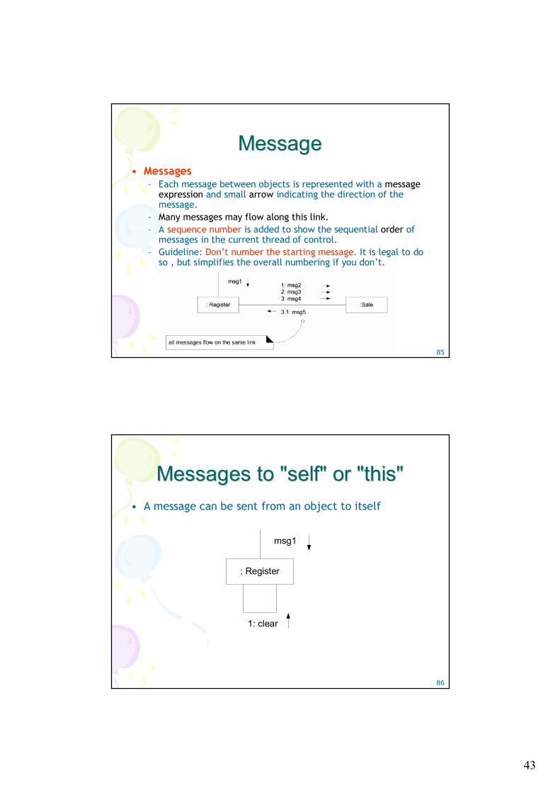
Basic Communication Diagram Basic Communication Diagram Notation Notation
• A link is a connection path between two objects; – It indicates some form of navigation and visibility between the
objects is possible– More formally, a link is an instance of an association.
Note that multiple messages, and messages both ways, flow along the same single link. There isn't one link line per message; all messages flow on the same line, which is like a road allowing two-way message traffic.
43
85
MessageMessage• Messages
– Each message between objects is represented with a message expression and small arrow indicating the direction of the message.
– Many messages may flow along this link.– A sequence number is added to show the sequential order of
messages in the current thread of control.– Guideline: Don’t number the starting message. It is legal to do
so , but simplifies the overall numbering if you don’t.
86
Messages to "self" or "this" Messages to "self" or "this" • A message can be sent from an object to itself
: Register
msg1
1: clear
44
87
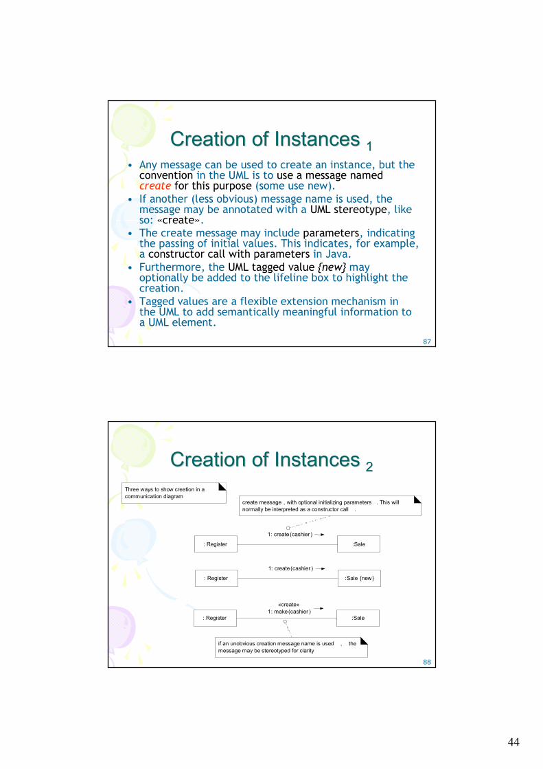
Creation of Instances Creation of Instances 11• Any message can be used to create an instance, but the
convention in the UML is to use a message named create for this purpose (some use new).
• If another (less obvious) message name is used, the message may be annotated with a UML stereotype, like so: «create».
• The create message may include parameters, indicating the passing of initial values. This indicates, for example, a constructor call with parameters in Java.
• Furthermore, the UML tagged value {new} may optionally be added to the lifeline box to highlight the creation.
• Tagged values are a flexible extension mechanism in the UML to add semantically meaningful information to a UML element.
88
Creation of Instances Creation of Instances 22
1: create (cashier )
: Register :Sale
create message , with optional initializing parameters . This will normally be interpreted as a constructor call .
«create»1: make(cashier )
: Register :Sale
if an unobvious creation message name is used , the message may be stereotyped for clarity
1: create (cashier )
: Register :Sale {new}
Three ways to show creation in a communication diagram
45
89
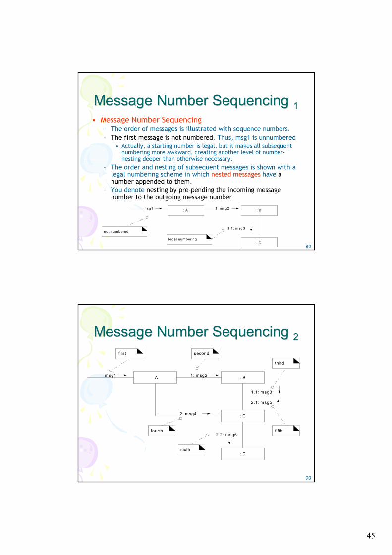
Message Number Sequencing Message Number Sequencing 11• Message Number Sequencing
– The order of messages is illustrated with sequence numbers.– The first message is not numbered. Thus, msg1 is unnumbered
• Actually, a starting number is legal, but it makes all subsequent numbering more awkward, creating another level of number-nesting deeper than otherwise necessary.
– The order and nesting of subsequent messages is shown with a legal numbering scheme in which nested messages have a number appended to them.
– You denote nesting by pre-pending the incoming message number to the outgoing message number
: Amsg1 : B1: msg2
: C
1.1: msg3not numbered
legal numbering
90
Message Number Sequencing Message Number Sequencing 22
: Amsg1 : B1: msg2
: C
1.1: msg3
2.1: msg5
2: msg4
: D
2.2: msg6
first second
fourth
sixth
fifth
third
46
91
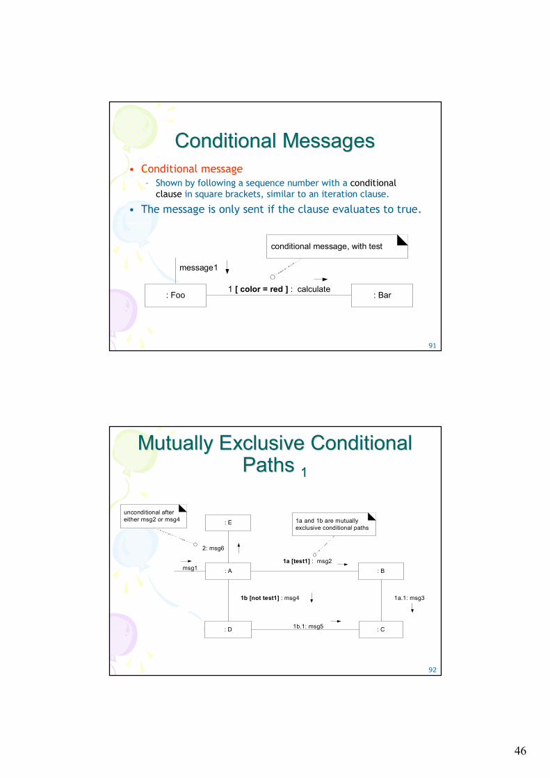
Conditional MessagesConditional Messages• Conditional message
– Shown by following a sequence number with a conditional clause in square brackets, similar to an iteration clause.
• The message is only sent if the clause evaluates to true.
1 [ color = red ] : calculate: Foo : Bar
message1
conditional message, with test
92
Mutually Exclusive Conditional Mutually Exclusive Conditional Paths Paths 11
1a [test1] : msg2: A : B
: C
1a.1: msg3
msg1
: D
1b [not test1] : msg4
1b.1: msg5
: E
2: msg6
unconditional after either msg2 or msg4 1a and 1b are mutually
exclusive conditional paths
47
93
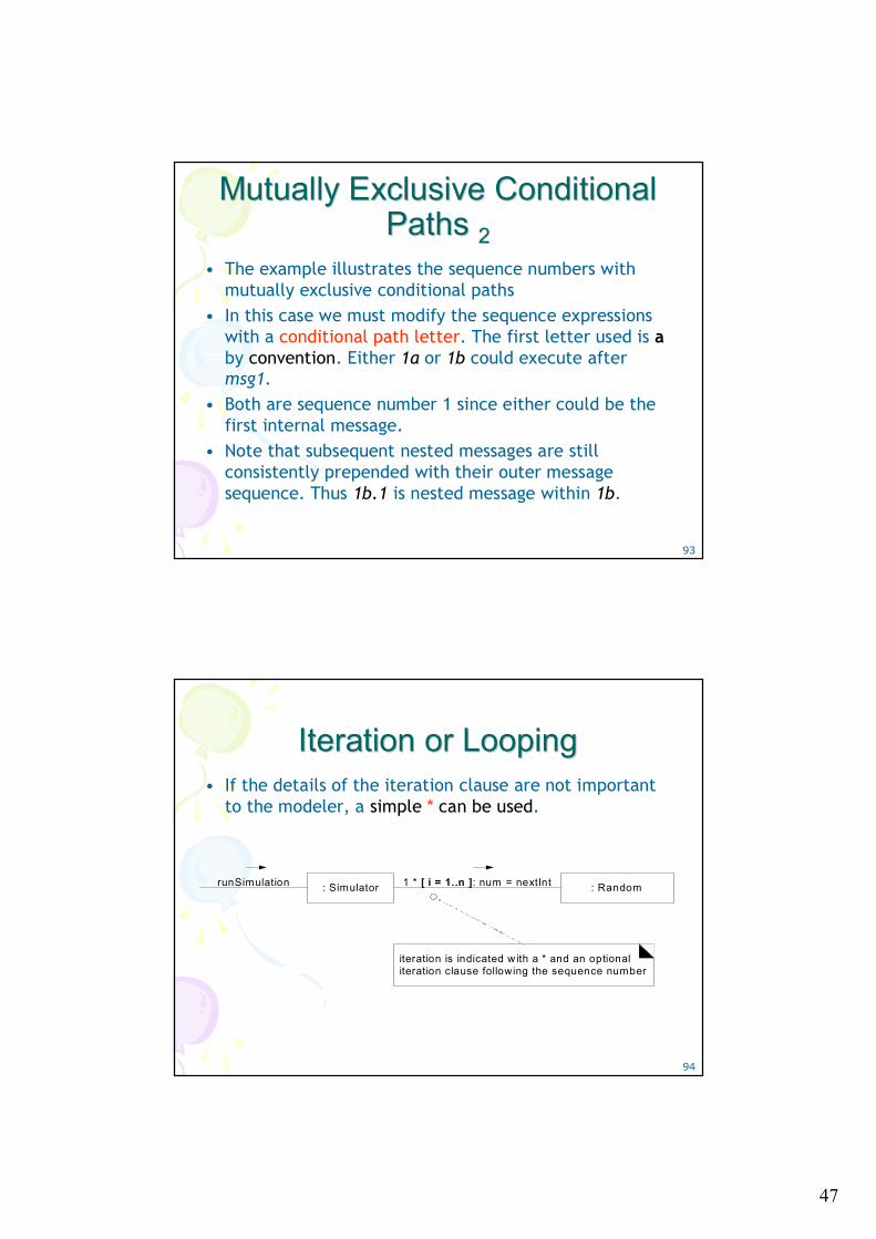
Mutually Exclusive Conditional Mutually Exclusive Conditional Paths Paths 22
• The example illustrates the sequence numbers with mutually exclusive conditional paths
• In this case we must modify the sequence expressions with a conditional path letter. The first letter used is aby convention. Either 1a or 1b could execute after msg1.
• Both are sequence number 1 since either could be the first internal message.
• Note that subsequent nested messages are still consistently prepended with their outer message sequence. Thus 1b.1 is nested message within 1b.
94
Iteration or LoopingIteration or Looping• If the details of the iteration clause are not important
to the modeler, a simple * can be used.
1 * [ i = 1..n ]: num = nextInt: SimulatorrunSimulation : Random
iteration is indicated w ith a * and an optional iteration clause following the sequence number
48
95
Iteration Over a Collection Iteration Over a Collection
96
Messages to a Classes to Messages to a Classes to Invoke Static Methods Invoke Static Methods
1: locs = getAvailableLocales: Foo «metaclass»
Calendar
doX
message to class, or a static method call
49
97
Polymorphic Messages and Polymorphic Messages and Cases Cases
:Register authorizedoX :Payment {abstract}
polymorphic message
object in role of abstract superclass
:DebitPayment
authorize
:Foo
stop at this point – don’t show any further details for this message
separate diagrams for each polymorphic concrete case
doAdoB :CreditPayment
authorize
:BardoX
98
Asynchronous and Synchronous Asynchronous and Synchronous Calls Calls
3: runFinalization:ClockStarter System : Class
startClock
:Clock
1: create
2: runasynchronous message
active object
50
Chapter 16Chapter 16UML Class UML Class Diagrams Diagrams
100
Introduction Introduction • Objective of this chapter
– Provide a reference for frequently used UML class diagram notation
• The UML includes class diagrams to illustrate classes, interfaces, and their associations. They are used for static object modeling
51
101
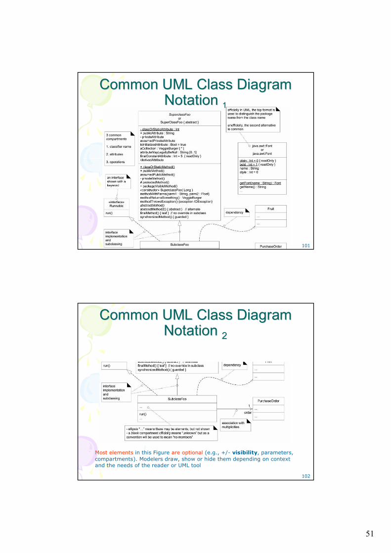
Common UML Class Diagram Common UML Class Diagram Notation Notation 11
102
Common UML Class Diagram Common UML Class Diagram Notation Notation 22
Most elements in this Figure are optional (e.g., +/- visibility, parameters, compartments). Modelers draw, show or hide them depending on context and the needs of the reader or UML tool
52
103
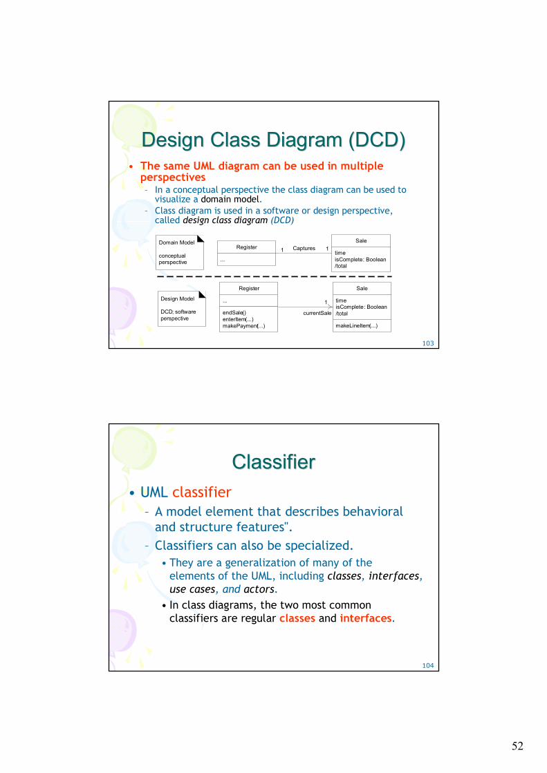
Design Class Diagram (DCD)Design Class Diagram (DCD)• The same UML diagram can be used in multiple
perspectives– In a conceptual perspective the class diagram can be used to
visualize a domain model. – Class diagram is used in a software or design perspective,
called design class diagram (DCD)
Register
...
endSale()enterItem(...)makePayment(...)
Sale
timeisComplete: Boolean/total
makeLineItem(...)
Register
...
Sale
timeisComplete: Boolean/total
Captures
1
11Domain Model
conceptual perspective
Design Model
DCD; software perspective
currentSale
104
Classifier Classifier • UML classifier
– A model element that describes behavioral and structure features".
– Classifiers can also be specialized. • They are a generalization of many of the
elements of the UML, including classes, interfaces, use cases, and actors.
• In class diagrams, the two most common classifiers are regular classes and interfaces.
53
105
Ways to Show UML Attributes: Attribute Ways to Show UML Attributes: Attribute Text and Association LinesText and Association Lines
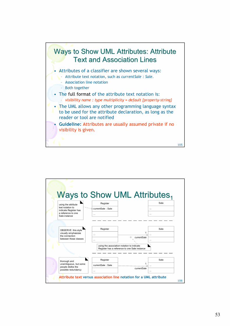
• Attributes of a classifier are shown several ways:– Attribute text notation, such as currentSale : Sale.– Association line notation– Both together
• The full format of the attribute text notation is:– visibility name : type multiplicity = default {property-string}
• The UML allows any other programming language syntax to be used for the attribute declaration, as long as the reader or tool are notified
• Guideline: Attributes are usually assumed private if no visibility is given.
106
Ways to Show UML AttributesWays to Show UML Attributes11
Register
...
...
Sale
...
...
1
Register
currentSale : Sale
...
Sale
...
...
using the attribute text notation to indicate Register has a reference to one Sale instance
using the association notation to indicate Register has a reference to one Sale instance
OBSERVE: this style visually emphasizes the connection between these classes currentSale
Register
currentSale : Sale
...
Sale
...
...
1thorough and unambiguous, but some people dislike the possible redundancy currentSale
Attribute text versus association line notation for a UML attribute
54
107
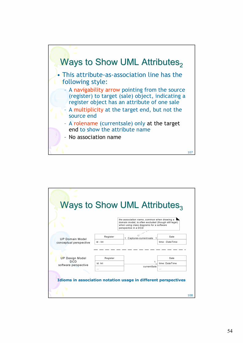
Ways to Show UML AttributesWays to Show UML Attributes22• This attribute-as-association line has the
following style:– A navigability arrow pointing from the source
(register) to target (sale) object, indicating a register object has an attribute of one sale
– A multiplicity at the target end, but not the source end
– A rolename (currentsale) only at the target end to show the attribute name
– No association name
108
Ways to Show UML AttributesWays to Show UML Attributes33
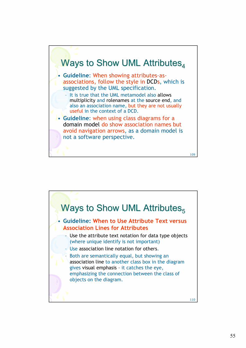
the association nam e, common when drawing a dom ain model, is often excluded (though still legal) when using class diagrams for a software perspective in a DCD
Register
id: Int
...
Sale
time: DateTime
...
1
currentSale
Register
id : Int
Sale
time : DateTimeCaptures-current-sale1 1UP Domain Model
conceptual perspective
UP Design ModelDCD
software perspective
Idioms in association notation usage in different perspectives
55
109
Ways to Show UML AttributesWays to Show UML Attributes44• Guideline: When showing attributes-as-
associations, follow the style in DCDs, which is suggested by the UML specification.– It is true that the UML metamodel also allows
multiplicity and rolenames at the source end, and also an association name, but they are not usually useful in the context of a DCD.
• Guideline: when using class diagrams for a domain model do show association names but avoid navigation arrows, as a domain model is not a software perspective.
110
Ways to Show UML AttributesWays to Show UML Attributes55• Guideline: When to Use Attribute Text versus
Association Lines for Attributes– Use the attribute text notation for data type objects
(where unique identify is not important) – Use association line notation for others. – Both are semantically equal, but showing an
association line to another class box in the diagram gives visual emphasis - it catches the eye, emphasizing the connection between the class of objects on the diagram.
56
111
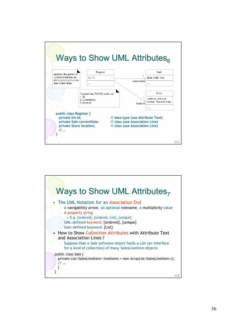
Ways to Show UML AttributesWays to Show UML Attributes66
public class Register { private int id; // data type (use Attribute Text)private Sale currentSale; // class (use Association Line) private Store location; // class (use Association Line) // …
}
112
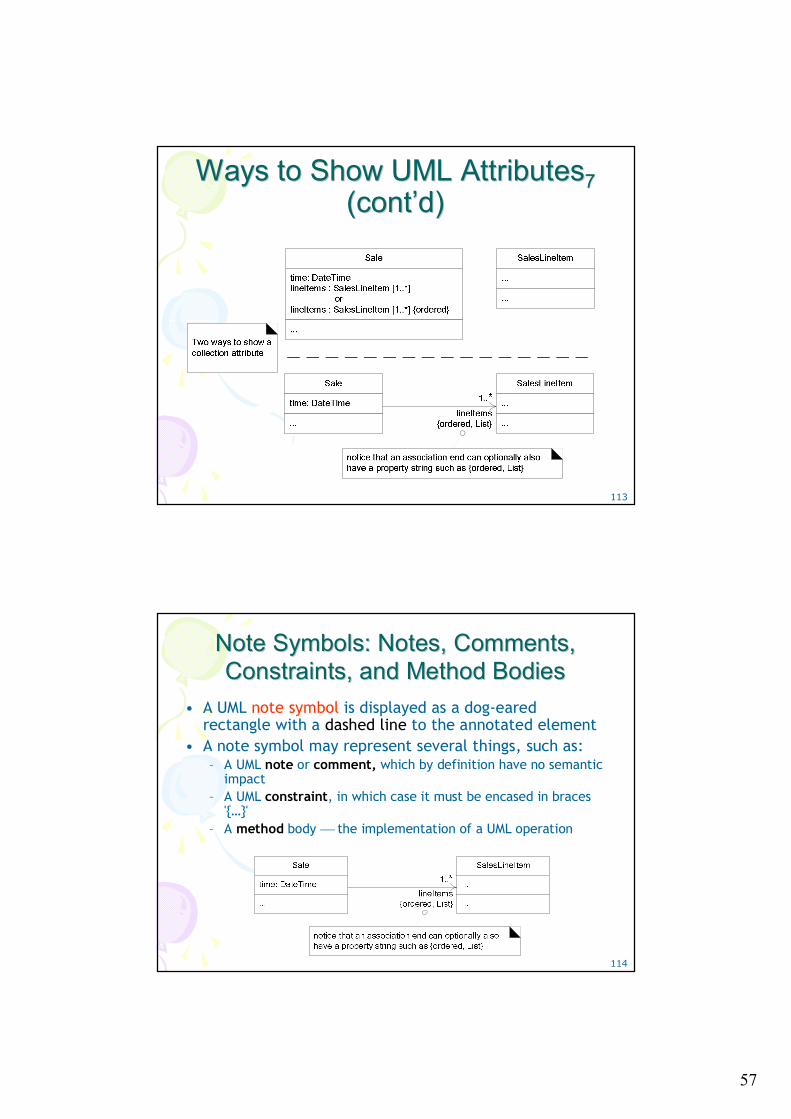
Ways to Show UML AttributesWays to Show UML Attributes77• The UML Notation for an Association End
– A navigability arrow, an optional rolename, a multiplicity value– A property string
• E.g. {ordered}, {ordered, List}, {unique}– UML-defined keyword: {ordered}, {unique}– User-defined keyword: {List}
• How to Show Collection Attributes with Attribute Text and Association Lines ?– Suppose that a Sale software object holds a List (an interface
for a kind of collection) of many SalesLineItem objects
public class Sale { private List<SalesLineItem> lineItems = new ArrayList<SalesLineItem>(); // …}
}
57
113
Ways to Show UML AttributesWays to Show UML Attributes7 7 (cont(cont’’d)d)
114
Note Symbols: Notes, Comments, Note Symbols: Notes, Comments, Constraints, and Method BodiesConstraints, and Method Bodies
• A UML note symbol is displayed as a dog-eared rectangle with a dashed line to the annotated element
• A note symbol may represent several things, such as:– A UML note or comment, which by definition have no semantic
impact– A UML constraint, in which case it must be encased in braces
'{…}' – A method body ⎯ the implementation of a UML operation
58
115
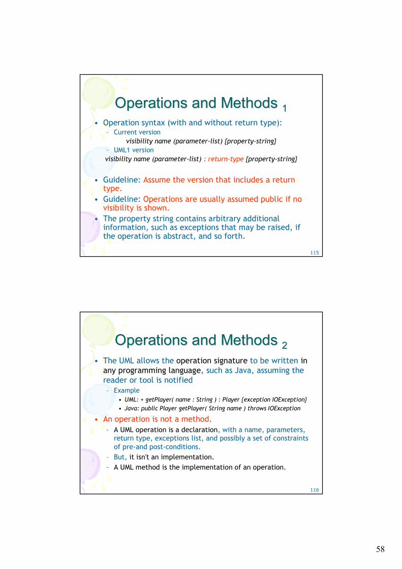
Operations and Methods Operations and Methods 11• Operation syntax (with and without return type):
– Current versionvisibility name (parameter-list) {property-string}
– UML1 versionvisibility name (parameter-list) : return-type {property-string}
• Guideline: Assume the version that includes a return type.
• Guideline: Operations are usually assumed public if no visibility is shown.
• The property string contains arbitrary additional information, such as exceptions that may be raised, if the operation is abstract, and so forth.
116
Operations and Methods Operations and Methods 22• The UML allows the operation signature to be written in
any programming language, such as Java, assuming the reader or tool is notified – Example
• UML: + getPlayer( name : String ) : Player {exception IOException} • Java: public Player getPlayer( String name ) throws IOException
• An operation is not a method.– A UML operation is a declaration, with a name, parameters,
return type, exceptions list, and possibly a set of constraints of pre-and post-conditions.
– But, it isn't an implementation.– A UML method is the implementation of an operation.
59
117
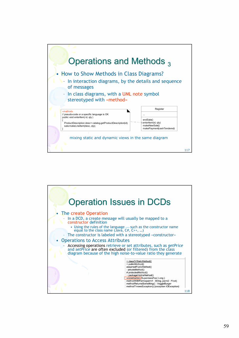
Operations and Methods Operations and Methods 33• How to Show Methods in Class Diagrams?
– In interaction diagrams, by the details and sequence of messages
– In class diagrams, with a UML note symbol stereotyped with «method»
Register
...
endSale()enterItem(id, qty)makeNewSale()makePayment(cashTendered)
«method»// pseudo-code or a specific language is OKpublic void enterItem( id, qty ){
ProductDescription desc= catalog.getProductDescription(id);sale.makeLineItem(desc, qty);
}
mixing static and dynamic views in the same diagram
118
Operation Issues in Operation Issues in DCDsDCDs• The create Operation
– In a DCD, a create message will usually be mapped to a constructor definition
• Using the rules of the language ⎯ such as the constructor name equal to the class name (Java, C#, C++, …)
– The constructor is labeled with a stereotyped «constructor»• Operations to Access Attributes
– Accessing operations retrieve or set attributes, such as getPriceand setPrice are often excluded (or filtered) from the class diagram because of the high noise-to-value ratio they generate
60
119
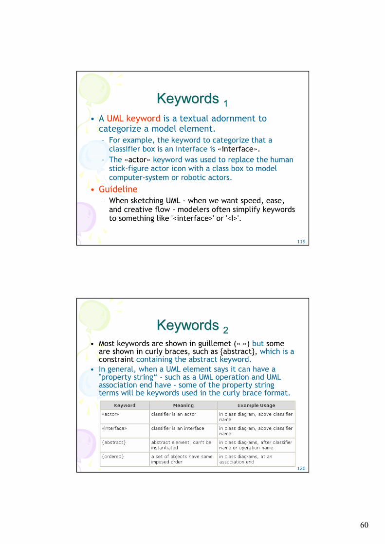
Keywords Keywords 11• A UML keyword is a textual adornment to
categorize a model element. – For example, the keyword to categorize that a
classifier box is an interface is «interface».– The «actor» keyword was used to replace the human
stick-figure actor icon with a class box to model computer-system or robotic actors.
• Guideline– When sketching UML - when we want speed, ease,
and creative flow - modelers often simplify keywords to something like '<interface>' or '<I>'.
120
Keywords Keywords 22• Most keywords are shown in guillemet (« ») but some
are shown in curly braces, such as {abstract}, which is a constraint containing the abstract keyword.
• In general, when a UML element says it can have a "property string“ - such as a UML operation and UML association end have - some of the property string terms will be keywords used in the curly brace format.
61
121
Stereotypes, Profiles, and Tags Stereotypes, Profiles, and Tags • Stereotypes
– Are shown with guillemets symbols – Represent a refinement of an existing modeling concept and
is defined within a UML profile; for a specific domain.– The UML predefines many stereotypes, such as «destroy»
(used on sequence diagrams), and also allows user-defined ones.
– Stereotypes provide an extension mechanism in the UML• Profiles
– A collection of related stereotypes, tags, and constraints to specialize the use of the UML for a specific domain or platform
– For example, UML profile for project management or for data modeling.
122
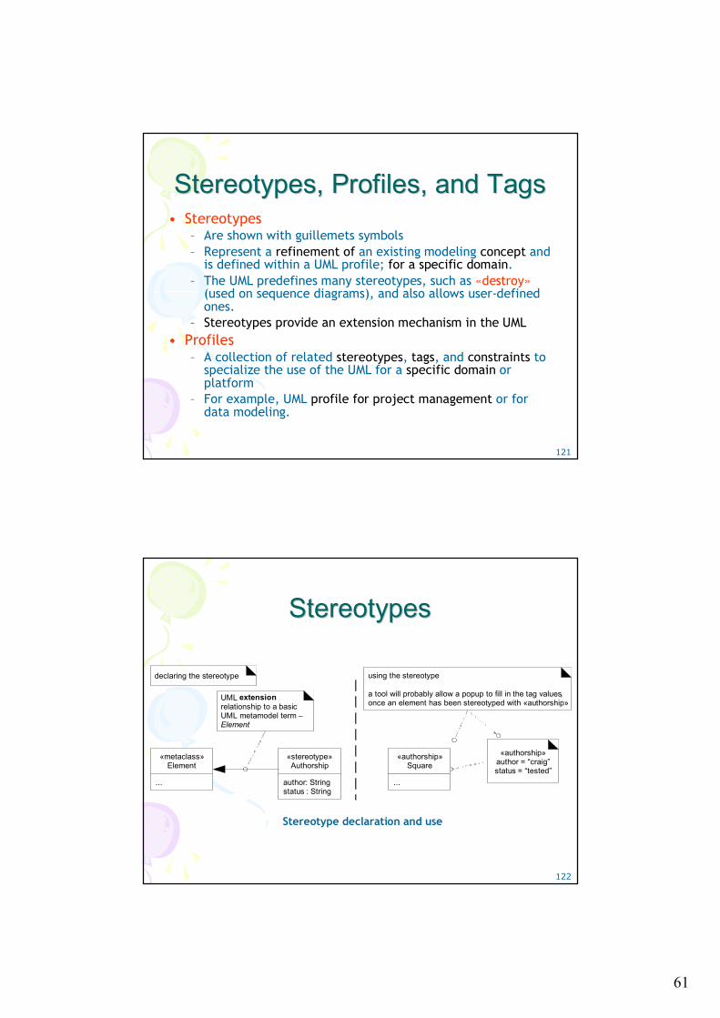
StereotypesStereotypes
«stereotype»Authorship
author: Stringstatus : String
UML extension relationship to a basic UML metamodel term –Element
«authorship»author = “craig”status = “tested”
«metaclass»Element
...
«authorship»Square
...
using the stereotype
a tool will probably allow a popup to fill in the tag values, once an element has been stereotyped with «authorship»
declaring the stereotype
Stereotype declaration and use
62
123
Property and Property StringProperty and Property String• In the UML, a property is "a named value denoting a
characteristic of an element. A property has semantic impact." – Some properties are predefined in the UML, such as visibility -
a property of an operation. – Others can be user-defined.
• Textual presentation approach– UML property string {name1=value1, name2=value2}, such as
{abstract, visibility=public}. – Some properties are shown without a value, such as {abstract};
• This usually implies a boolean property, shorthand for {abstract=true}.
– Note that {abstract} is both an example of a constraint and a property string
124
GeneralizationGeneralization• Generalization in the UML is shown with a solid line
and fat triangular arrow from the subclass to superclass– A taxonomic relationship between a more general classifier and
a more specific classifier. – Each instance of the specific classifier is also an indirect
instance of the general classifier. – Thus, the specific classifier indirectly has features of the more
general classifier.
• Generalization inheritance? (Are they the same?)– It depends. – In a domain model conceptual-perspective class diagram, the
answer is no.• It implies the superclass is a superset and the subclass is a subset
– In a DCD software-perspective class diagram, it implies OOPL inheritance from the superclass to subclass. Yes.
63
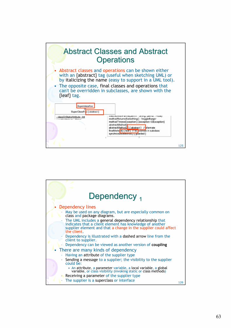
125
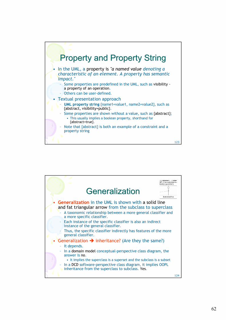
Abstract Classes and Abstract Abstract Classes and Abstract OperationsOperations
• Abstract classes and operations can be shown either with an {abstract} tag (useful when sketching UML) or by italicizing the name (easy to support in a UML tool).
• The opposite case, final classes and operations that can't be overridden in subclasses, are shown with the {leaf} tag.
126
Dependency Dependency 11• Dependency lines
– May be used on any diagram, but are especially common on class and package diagrams.
– The UML includes a general dependency relationship that indicates that a client element has knowledge of another supplier element and that a change in the supplier could affect the client.
– Dependency is illustrated with a dashed arrow line from the client to supplier.
– Dependency can be viewed as another version of coupling• There are many kinds of dependency
– Having an attribute of the supplier type– Sending a message to a supplier; the visibility to the supplier
could be: • An attribute, a parameter variable, a local variable, a global
variable, or class visibility (invoking static or class methods)– Receiving a parameter of the supplier type– The supplier is a superclass or interface
64
127
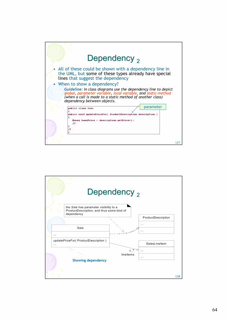
Dependency Dependency 22• All of these could be shown with a dependency line in
the UML, but some of these types already have special lines that suggest the dependency
• When to show a dependency?– Guideline: In class diagrams use the dependency line to depict
global, parameter variable, local variable, and static-method (when a call is made to a static method of another class) dependency between objects.
parameter
128
Dependency Dependency 22
SalesLineItem
...
...
ProductDescription
...
...
1..*lineItems
Sale
...
updatePriceFor( ProductDescription )...
the Sale has parameter visibility to a ProductDescription , and thus some kind of dependency
Showing dependency
65
129
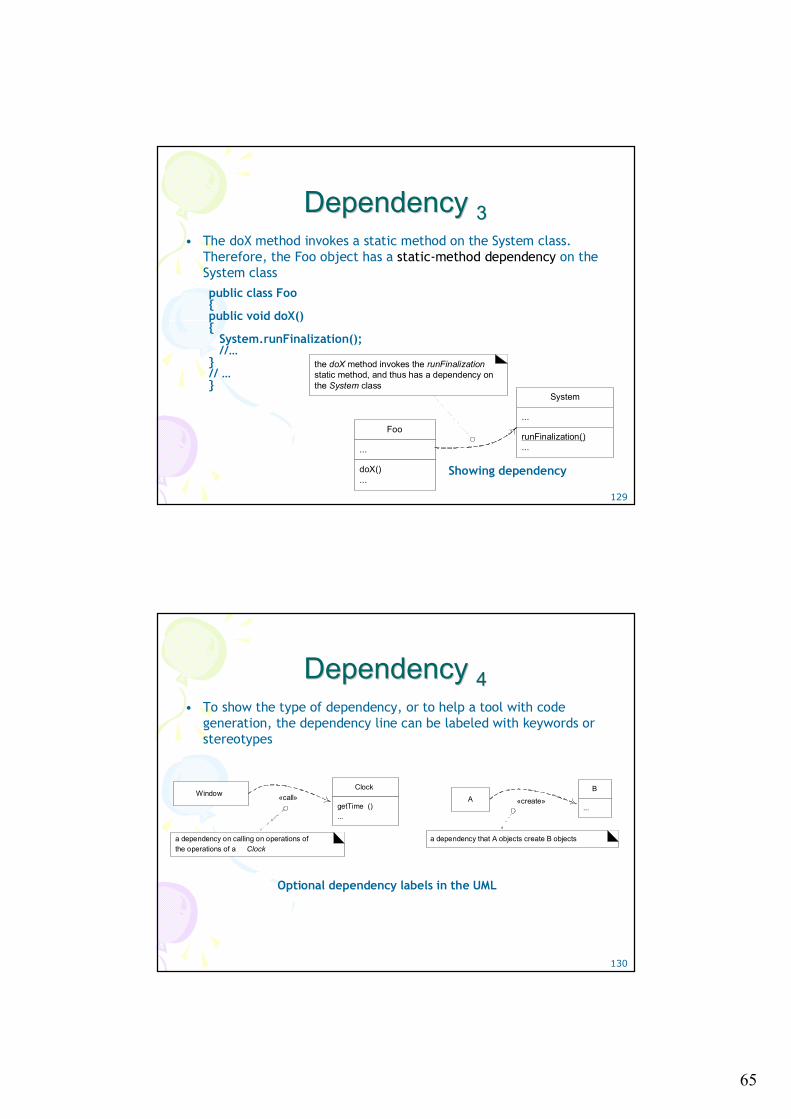
Dependency Dependency 33• The doX method invokes a static method on the System class.
Therefore, the Foo object has a static-method dependency on the System class
System
...
runFinalization()...
Foo
...
doX()...
the doX method invokes the runFinalization static method, and thus has a dependency on the System class
public class Foo{public void doX(){
System.runFinalization();//…
}// …}
Showing dependency
130
Dependency Dependency 44• To show the type of dependency, or to help a tool with code
generation, the dependency line can be labeled with keywords or stereotypes
«call»Window
a dependency on calling on operations of the operations of a Clock
Clock
getTime ()...
«create»A
a dependency that A objects create B objects
B
...
Optional dependency labels in the UML
66
131
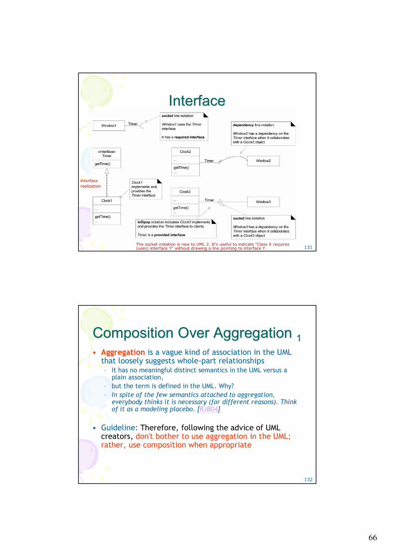
InterfaceInterface
interface realization
The socket notation is new to UML 2. It's useful to indicate "Class X requires (uses) interface Y" without drawing a line pointing to interface Y
132
Composition Over Aggregation Composition Over Aggregation 11• Aggregation is a vague kind of association in the UML
that loosely suggests whole-part relationships– It has no meaningful distinct semantics in the UML versus a
plain association, – but the term is defined in the UML. Why? – In spite of the few semantics attached to aggregation,
everybody thinks it is necessary (for different reasons). Think of it as a modeling placebo. [RJB04]
• Guideline: Therefore, following the advice of UML creators, don't bother to use aggregation in the UML; rather, use composition when appropriate
67
133
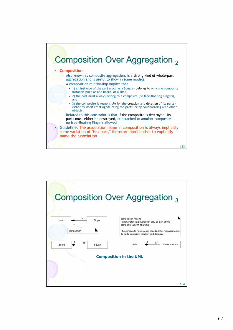
Composition Over Aggregation Composition Over Aggregation 22• Composition
– Also known as composite aggregation, is a strong kind of whole-partaggregation and is useful to show in some models.
– A composition relationship implies that • 1) an instance of the part (such as a Square) belongs to only one composite
instance (such as one Board) at a time, • 2) the part must always belong to a composite (no free-floating Fingers),
and • 3) the composite is responsible for the creation and deletion of its parts -
either by itself creating/deleting the parts, or by collaborating with other objects.
– Related to this constraint is that if the composite is destroyed, its parts must either be destroyed, or attached to another composite ⎯no free-floating Fingers allowed
• Guideline: The association name in composition is always implicitly some variation of "Has-part," therefore don't bother to explicitly name the association
134
Composition Over Aggregation Composition Over Aggregation 33
Finger0..7
Hand
composition
1
Square40
Board1
SalesLineItem1..*
Sale1
composition means -a part instance (Square) can only be part of one composite (Board) at a time
-the composite has sole responsibility for management of its parts, especially creation and deletion
Composition in the UML
68
135
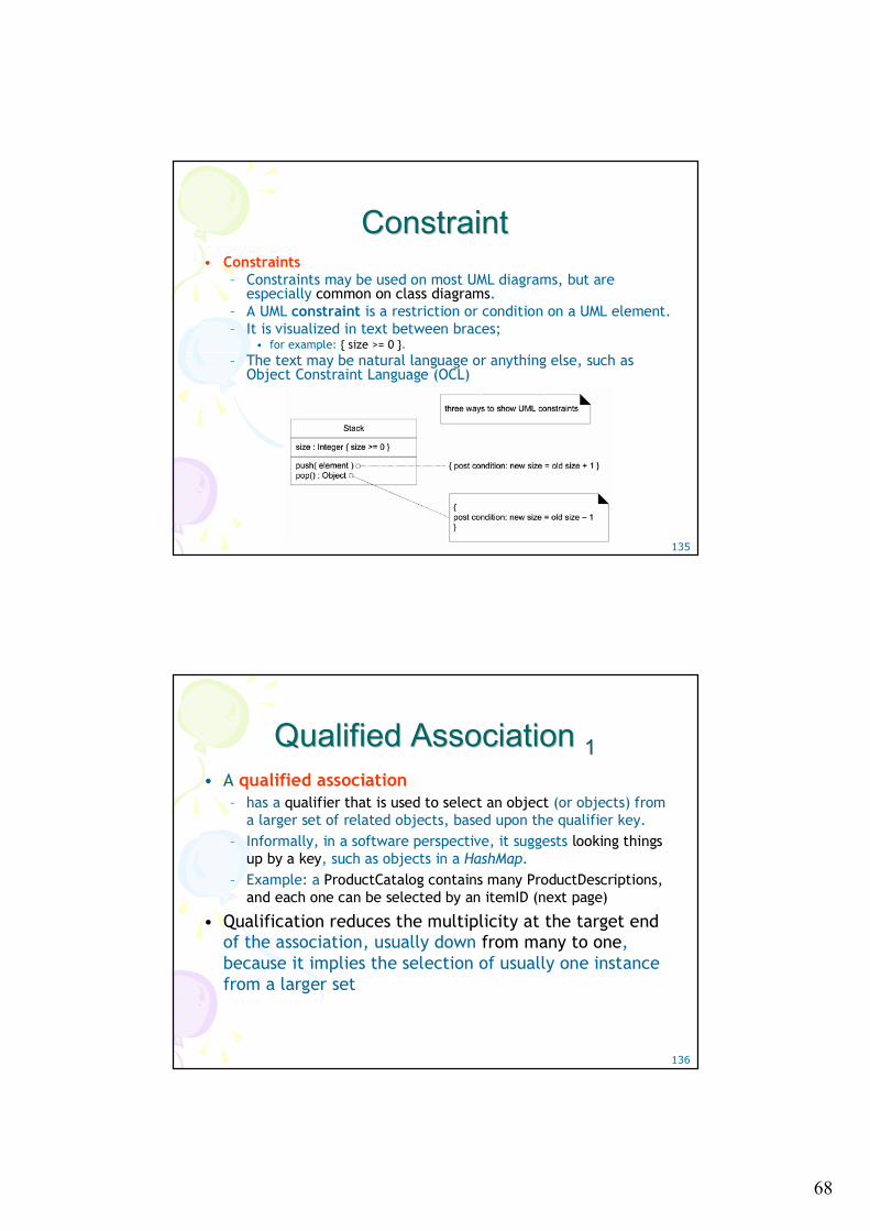
ConstraintConstraint• Constraints
– Constraints may be used on most UML diagrams, but are especially common on class diagrams.
– A UML constraint is a restriction or condition on a UML element. – It is visualized in text between braces;
• for example: { size >= 0 }. – The text may be natural language or anything else, such as
Object Constraint Language (OCL)
136
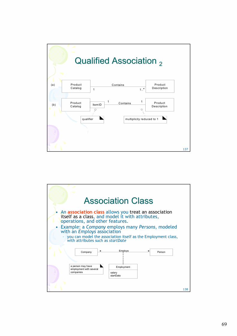
Qualified Association Qualified Association 11• A qualified association
– has a qualifier that is used to select an object (or objects) from a larger set of related objects, based upon the qualifier key.
– Informally, in a software perspective, it suggests looking things up by a key, such as objects in a HashMap.
– Example: a ProductCatalog contains many ProductDescriptions, and each one can be selected by an itemID (next page)
• Qualification reduces the multiplicity at the target endof the association, usually down from many to one, because it implies the selection of usually one instance from a larger set
69
137
Qualified Association Qualified Association 22
ProductCatalog
ProductDescriptionitemID Contains
ProductCatalog
ProductDescription
Contains
1..*
multiplicity reduced to 1
(a)
(b)
qualifier
1
11
138
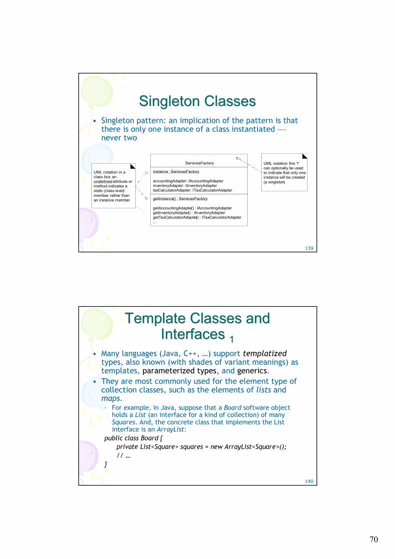
Association Class Association Class • An association class allows you treat an association
itself as a class, and model it with attributes, operations, and other features.
• Example: a Company employs many Persons, modeled with an Employs association– you can model the association itself as the Employment class,
with attributes such as startDate
salarystartDate
Employment
EmploysCompany Person**
a person may have employment with several companies
70
139
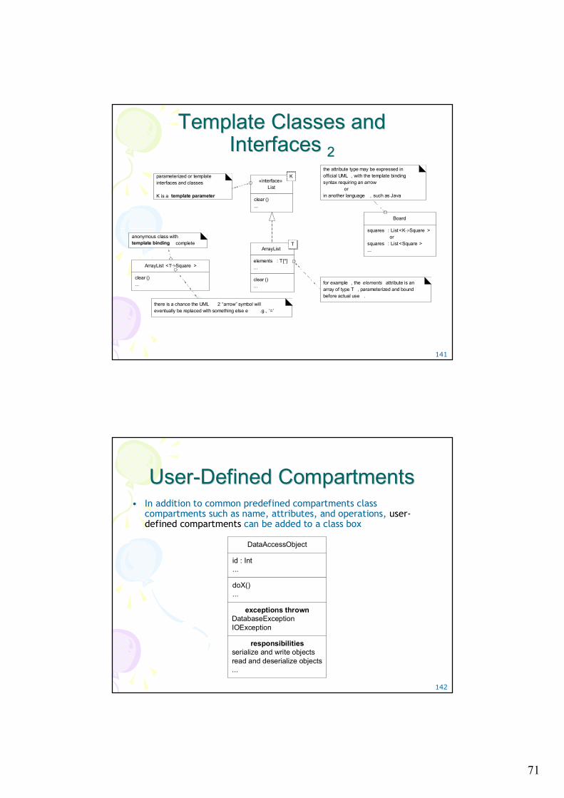
Singleton Classes Singleton Classes • Singleton pattern: an implication of the pattern is that
there is only one instance of a class instantiated ⎯never two
1ServicesFactory
instance : ServicesFactory
accountingAdapter: IAccountingAdapterinventoryAdapter : IInventoryAdaptertaxCalculatorAdapter: ITaxCalculatorAdapter
getInstance() : ServicesFactory
getAccountingAdapter() : IAccountingAdaptergetInventoryAdapter() : IInventoryAdaptergetTaxCalculatorAdapter() : ITaxCalculatorAdapter...
UML notation: in a class box, an underlined attribute or method indicates a static (class level) member, rather than an instance member
UML notation: this '1' can optionally be used to indicate that only one instance will be created (a singleton)
140
Template Classes and Template Classes and Interfaces Interfaces 11
• Many languages (Java, C++, …) support templatizedtypes, also known (with shades of variant meanings) as templates, parameterized types, and generics.
• They are most commonly used for the element type of collection classes, such as the elements of lists and maps. – For example, in Java, suppose that a Board software object
holds a List (an interface for a kind of collection) of many Squares. And, the concrete class that implements the List interface is an ArrayList:
public class Board { private List<Square> squares = new ArrayList<Square>(); // …
}
71
141
Template Classes and Template Classes and Interfaces Interfaces 22
«interface»List
clear ()...
Kparameterized or template interfaces and classes
K is a template parameter
anonymous class with template binding complete
Board
squares : List <K Square >or
squares : List <Square >...
ArrayList <T Square >
clear ()...
the attribute type may be expressed in official UML , with the template binding syntax requiring an arrow
orin another language , such as Java
ArrayList
elements : T[*]...
clear ()...
T
for example , the elements attribute is an array of type T , parameterized and bound before actual use .
there is a chance the UML 2 “arrow” symbol will eventually be replaced with something else e .g., ‘=’
142
UserUser--Defined Compartments Defined Compartments • In addition to common predefined compartments class
compartments such as name, attributes, and operations, user-defined compartments can be added to a class box
DataAccessObject
id : Int...
doX()...
exceptions thrownDatabaseExceptionIOException
responsibilitiesserialize and write objectsread and deserialize objects...
72
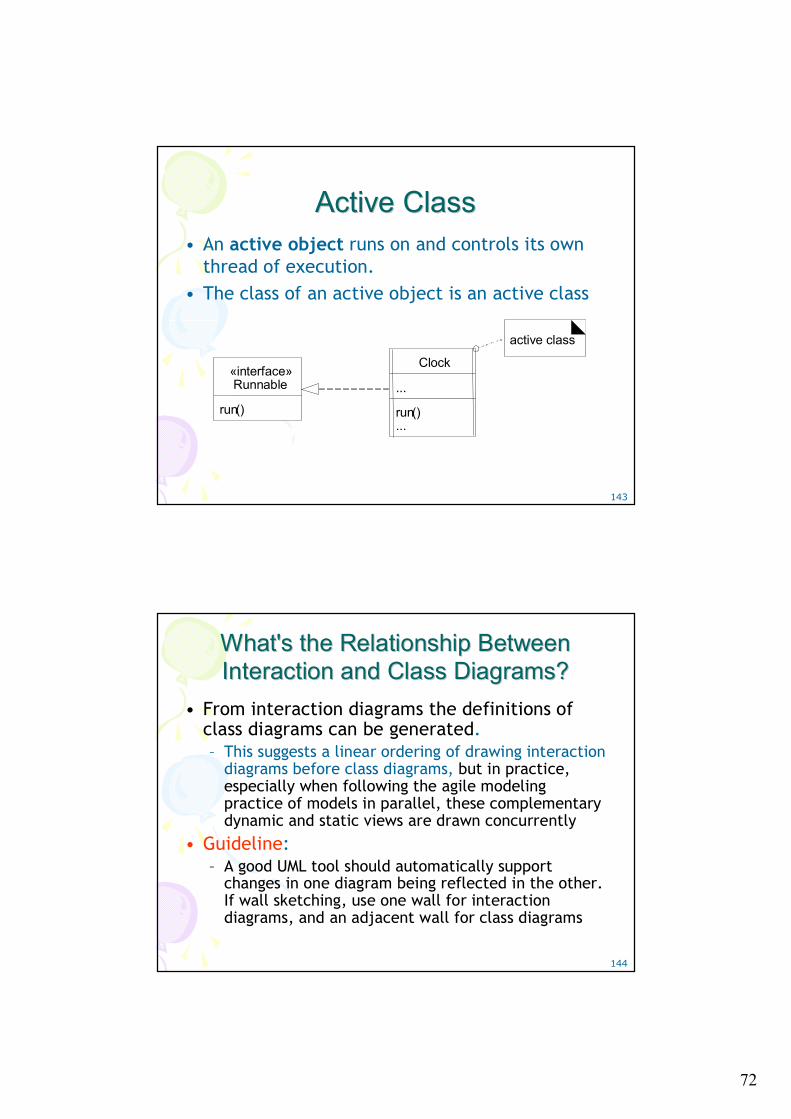
143
Active Class Active Class • An active object runs on and controls its own
thread of execution. • The class of an active object is an active class
«interface»Runnable
run()
Clock
...
run()...
active class
144
What's the Relationship Between What's the Relationship Between Interaction and Class Diagrams?Interaction and Class Diagrams?
• From interaction diagrams the definitions of class diagrams can be generated. – This suggests a linear ordering of drawing interaction
diagrams before class diagrams, but in practice, especially when following the agile modeling practice of models in parallel, these complementary dynamic and static views are drawn concurrently
• Guideline: – A good UML tool should automatically support
changes in one diagram being reflected in the other. If wall sketching, use one wall for interaction diagrams, and an adjacent wall for class diagrams

73
145
Relationship Between Interaction Relationship Between Interaction and Class Diagramsand Class Diagrams
: Register : Sale
makePayment(cashTendered)
makePayment(cashTendered)
Register
...
makePayment(…)...
Sale
...
makePayment(…)...
1
currentSale
messages in interaction diagrams indicate operations in the class diagrams classes
identified in the interaction diagrams are declared in the class diagrams
The influence of interaction diagrams on class diagrams