Embed Size (px)
Citation preview
7/15/2011
1
Chapter 13: Direct Memory Access
and DMA-Controlled I/O Copyright ©2009 by Pearson Education, Inc.
Upper Saddle River, New Jersey 07458 • All rights reserved.
The Intel Microprocessors: 8086/8088, 80186/80188, 80286, 80386, 80486 Pentium,
Pentium Pro Processor, Pentium II, Pentium, 4, and Core2 with 64-bit Extensions
Architecture, Programming, and Interfacing, Eighth Edition
Barry B. Brey
Introduction
• The DMA I/O technique provides direct access
to the memory while the microprocessor is
temporarily disabled.
• This chapter also explains the operation of
disk memory systems and video systems that
are often DMA-processed.
• Disk memory includes floppy, fixed, and
optical disk storage. Video systems include
digital and analog monitors.
2
Copyright ©2009 by Pearson Education, Inc.
Upper Saddle River, New Jersey 07458 • All rights reserved.
The Intel Microprocessors: 8086/8088, 80186/80188, 80286, 80386, 80486 Pentium,
Pentium Pro Processor, Pentium II, Pentium, 4, and Core2 with 64-bit Extensions
Architecture, Programming, and Interfacing, Eighth Edition
Barry B. Brey
Chapter Objectives
• Describe a DMA transfer.
• Explain the operation of the HOLD and HLDA
direct memory access control signals.
• Explain the function of the 8237 DMA
controller when used for DMA transfers.
• Program the 8237 to accomplish DMA
transfers.
Upon completion of this chapter, you will be able to:
3
Copyright ©2009 by Pearson Education, Inc.
Upper Saddle River, New Jersey 07458 • All rights reserved.
The Intel Microprocessors: 8086/8088, 80186/80188, 80286, 80386, 80486 Pentium,
Pentium Pro Processor, Pentium II, Pentium, 4, and Core2 with 64-bit Extensions
Architecture, Programming, and Interfacing, Eighth Edition
Barry B. Brey
Chapter Objectives
• Describe the disk standards found in
personal computer systems.
• Describe the various video interface
standards found in the personal computer.
Upon completion of this chapter, you will be able to:
(cont.)
4
Copyright ©2009 by Pearson Education, Inc.
Upper Saddle River, New Jersey 07458 • All rights reserved.
The Intel Microprocessors: 8086/8088, 80186/80188, 80286, 80386, 80486 Pentium,
Pentium Pro Processor, Pentium II, Pentium, 4, and Core2 with 64-bit Extensions
Architecture, Programming, and Interfacing, Eighth Edition
Barry B. Brey
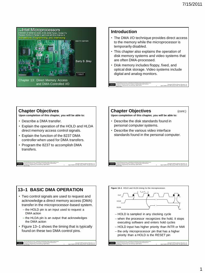
13–1 BASIC DMA OPERATION
• Two control signals are used to request and
acknowledge a direct memory access (DMA)
transfer in the microprocessor-based system.
– the HOLD pin is an input used to request a
DMA action
– the HLDA pin is an output that acknowledges
the DMA action
• Figure 13–1 shows the timing that is typically
found on these two DMA control pins.
5
Copyright ©2009 by Pearson Education, Inc.
Upper Saddle River, New Jersey 07458 • All rights reserved.
The Intel Microprocessors: 8086/8088, 80186/80188, 80286, 80386, 80486 Pentium,
Pentium Pro Processor, Pentium II, Pentium, 4, and Core2 with 64-bit Extensions
Architecture, Programming, and Interfacing, Eighth Edition
Barry B. Brey
Figure 13–1 HOLD and HLDA timing for the microprocessor.
– HOLD is sampled in any clocking cycle
– when the processor recognizes the hold, it stops
executing software and enters hold cycles
– HOLD input has higher priority than INTR or NMI
– the only microprocessor pin that has a higher
priority than a HOLD is the RESET pin
6

7/15/2011
2
Copyright ©2009 by Pearson Education, Inc.
Upper Saddle River, New Jersey 07458 • All rights reserved.
The Intel Microprocessors: 8086/8088, 80186/80188, 80286, 80386, 80486 Pentium,
Pentium Pro Processor, Pentium II, Pentium, 4, and Core2 with 64-bit Extensions
Architecture, Programming, and Interfacing, Eighth Edition
Barry B. Brey
• HLDA becomes active to indicate the
processor has placed its buses at high-
impedance state.
– as can be seen in the timing diagram, there are
a few clock cycles between the time that HOLD
changes and until HLDA changes
• HLDA output is a signal to the requesting
device that the processor has relinquished
control of its memory and I/O space.
– one could call HOLD input a DMA request
input and HLDA output a DMA grant signal
7
Copyright ©2009 by Pearson Education, Inc.
Upper Saddle River, New Jersey 07458 • All rights reserved.
The Intel Microprocessors: 8086/8088, 80186/80188, 80286, 80386, 80486 Pentium,
Pentium Pro Processor, Pentium II, Pentium, 4, and Core2 with 64-bit Extensions
Architecture, Programming, and Interfacing, Eighth Edition
Barry B. Brey
Basic DMA Definitions
• Direct memory accesses normally occur
between an I/O device and memory without
the use of the microprocessor.
– a DMA read transfers data from the memory
to the I/O device
– A DMA write transfers data from an I/O device
to memory
• Memory & I/O are controlled simultaneously.
– which is why the system contains separate
memory and I/O control signals
8
Copyright ©2009 by Pearson Education, Inc.
Upper Saddle River, New Jersey 07458 • All rights reserved.
The Intel Microprocessors: 8086/8088, 80186/80188, 80286, 80386, 80486 Pentium,
Pentium Pro Processor, Pentium II, Pentium, 4, and Core2 with 64-bit Extensions
Architecture, Programming, and Interfacing, Eighth Edition
Barry B. Brey
• A DMA read causes the MRDC and IOWC
signals to activate simultaneously.
– transferring data from memory to the I/O device
• A DMA write causes the MWTC and IORC
signals to both activate.
• 8086/8088 require a controller or circuit such
as shown in Fig 13–2 for control bus signal
generation.
• The DMA controller provides memory with its
address, and controller signal (DACK) selects
the I/O device during the transfer.
9
Copyright ©2009 by Pearson Education, Inc.
Upper Saddle River, New Jersey 07458 • All rights reserved.
The Intel Microprocessors: 8086/8088, 80186/80188, 80286, 80386, 80486 Pentium,
Pentium Pro Processor, Pentium II, Pentium, 4, and Core2 with 64-bit Extensions
Architecture, Programming, and Interfacing, Eighth Edition
Barry B. Brey
Figure 13–2 A circuit that generates system control signals in a DMA environment.
10
Copyright ©2009 by Pearson Education, Inc.
Upper Saddle River, New Jersey 07458 • All rights reserved.
The Intel Microprocessors: 8086/8088, 80186/80188, 80286, 80386, 80486 Pentium,
Pentium Pro Processor, Pentium II, Pentium, 4, and Core2 with 64-bit Extensions
Architecture, Programming, and Interfacing, Eighth Edition
Barry B. Brey
• Data transfer speed is determined by speed
of the memory device or a DMA controller.
– if memory speed is 50 ns, DMA transfers occur
at rates up to 1/50 ns or 20 M bytes per second
– if the DMA controller functions at a maximum
rate of 15 MHz with 50 ns memory, maximum
transfer rate is 15 MHz because the DMA
controller is slower than the memory
• In many cases, the DMA controller slows the
speed of the system when transfers occur.
11
Copyright ©2009 by Pearson Education, Inc.
Upper Saddle River, New Jersey 07458 • All rights reserved.
The Intel Microprocessors: 8086/8088, 80186/80188, 80286, 80386, 80486 Pentium,
Pentium Pro Processor, Pentium II, Pentium, 4, and Core2 with 64-bit Extensions
Architecture, Programming, and Interfacing, Eighth Edition
Barry B. Brey
• The switch to serial data transfers in modern
systems has made DMA is less important.
• The serial PCI Express bus transfers data at
rates exceeding DMA transfers.
• The SATA (serial ATA) interface for disk
drives uses serial transfers at the rate of 300
Mbps
– and has replaced DMA transfers for hard disks
• Serial transfers on main-boards between
components using can approach 20 Gbps
for the PCI Express connection.
12
7/15/2011
3
Copyright ©2009 by Pearson Education, Inc.
Upper Saddle River, New Jersey 07458 • All rights reserved.
The Intel Microprocessors: 8086/8088, 80186/80188, 80286, 80386, 80486 Pentium,
Pentium Pro Processor, Pentium II, Pentium, 4, and Core2 with 64-bit Extensions
Architecture, Programming, and Interfacing, Eighth Edition
Barry B. Brey
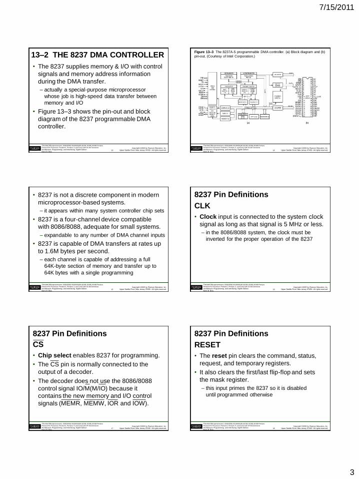
13–2 THE 8237 DMA CONTROLLER
• The 8237 supplies memory & I/O with control
signals and memory address information
during the DMA transfer.
– actually a special-purpose microprocessor
whose job is high-speed data transfer between
memory and I/O
• Figure 13–3 shows the pin-out and block
diagram of the 8237 programmable DMA
controller.
13
Copyright ©2009 by Pearson Education, Inc.
Upper Saddle River, New Jersey 07458 • All rights reserved.
The Intel Microprocessors: 8086/8088, 80186/80188, 80286, 80386, 80486 Pentium,
Pentium Pro Processor, Pentium II, Pentium, 4, and Core2 with 64-bit Extensions
Architecture, Programming, and Interfacing, Eighth Edition
Barry B. Brey
Figure 13–3 The 8237A-5 programmable DMA controller. (a) Block diagram and (b)
pin-out. (Courtesy of Intel Corporation.)
14
Copyright ©2009 by Pearson Education, Inc.
Upper Saddle River, New Jersey 07458 • All rights reserved.
The Intel Microprocessors: 8086/8088, 80186/80188, 80286, 80386, 80486 Pentium,
Pentium Pro Processor, Pentium II, Pentium, 4, and Core2 with 64-bit Extensions
Architecture, Programming, and Interfacing, Eighth Edition
Barry B. Brey
• 8237 is not a discrete component in modern
microprocessor-based systems.
– it appears within many system controller chip sets
• 8237 is a four-channel device compatible
with 8086/8088, adequate for small systems.
– expandable to any number of DMA channel inputs
• 8237 is capable of DMA transfers at rates up
to 1.6M bytes per second.
– each channel is capable of addressing a full
64K-byte section of memory and transfer up to
64K bytes with a single programming
15
Copyright ©2009 by Pearson Education, Inc.
Upper Saddle River, New Jersey 07458 • All rights reserved.
The Intel Microprocessors: 8086/8088, 80186/80188, 80286, 80386, 80486 Pentium,
Pentium Pro Processor, Pentium II, Pentium, 4, and Core2 with 64-bit Extensions
Architecture, Programming, and Interfacing, Eighth Edition
Barry B. Brey
8237 Pin Definitions
CLK
• Clock input is connected to the system clock
signal as long as that signal is 5 MHz or less.
– in the 8086/8088 system, the clock must be
inverted for the proper operation of the 8237
16
Copyright ©2009 by Pearson Education, Inc.
Upper Saddle River, New Jersey 07458 • All rights reserved.
The Intel Microprocessors: 8086/8088, 80186/80188, 80286, 80386, 80486 Pentium,
Pentium Pro Processor, Pentium II, Pentium, 4, and Core2 with 64-bit Extensions
Architecture, Programming, and Interfacing, Eighth Edition
Barry B. Brey
8237 Pin Definitions
CS
• Chip select enables 8237 for programming.
• The CS pin is normally connected to the
output of a decoder.
• The decoder does not use the 8086/8088
control signal IO/M(M/IO) because it
contains the new memory and I/O control
signals (MEMR, MEMW, IOR and IOW).
17
Copyright ©2009 by Pearson Education, Inc.
Upper Saddle River, New Jersey 07458 • All rights reserved.
The Intel Microprocessors: 8086/8088, 80186/80188, 80286, 80386, 80486 Pentium,
Pentium Pro Processor, Pentium II, Pentium, 4, and Core2 with 64-bit Extensions
Architecture, Programming, and Interfacing, Eighth Edition
Barry B. Brey
8237 Pin Definitions
RESET
• The reset pin clears the command, status,
request, and temporary registers.
• It also clears the first/last flip-flop and sets
the mask register.
– this input primes the 8237 so it is disabled
until programmed otherwise
18
7/15/2011
4
Copyright ©2009 by Pearson Education, Inc.
Upper Saddle River, New Jersey 07458 • All rights reserved.
The Intel Microprocessors: 8086/8088, 80186/80188, 80286, 80386, 80486 Pentium,
Pentium Pro Processor, Pentium II, Pentium, 4, and Core2 with 64-bit Extensions
Architecture, Programming, and Interfacing, Eighth Edition
Barry B. Brey
8237 Pin Definitions
READY
• A logic 0 on the ready input causes the
8237 to enter wait states for slower
memory components.
HLDA
• A hold acknowledge signals 8237 that the
microprocessor has relinquished control of
the address, data, and control buses.
19
Copyright ©2009 by Pearson Education, Inc.
Upper Saddle River, New Jersey 07458 • All rights reserved.
The Intel Microprocessors: 8086/8088, 80186/80188, 80286, 80386, 80486 Pentium,
Pentium Pro Processor, Pentium II, Pentium, 4, and Core2 with 64-bit Extensions
Architecture, Programming, and Interfacing, Eighth Edition
Barry B. Brey
8237 Pin Definitions
DREQ0–DREQ3
• DMA request inputs are used to request a
transfer for each of the four DMA channels.
– the polarity of these inputs is programmable, so
they are either active-high or active-low inputs
DB0–DB7
• Data bus pins are connected to the processor
data bus connections and used during the
programming of the DMA controller.
20
Copyright ©2009 by Pearson Education, Inc.
Upper Saddle River, New Jersey 07458 • All rights reserved.
The Intel Microprocessors: 8086/8088, 80186/80188, 80286, 80386, 80486 Pentium,
Pentium Pro Processor, Pentium II, Pentium, 4, and Core2 with 64-bit Extensions
Architecture, Programming, and Interfacing, Eighth Edition
Barry B. Brey
8237 Pin Definitions
IOR
• I/O read is a bidirectional pin used during
programming and during a DMA write cycle.
IOW
• I/O write is a bidirectional pin used during
programming and during a DMA read cycle.
21
Copyright ©2009 by Pearson Education, Inc.
Upper Saddle River, New Jersey 07458 • All rights reserved.
The Intel Microprocessors: 8086/8088, 80186/80188, 80286, 80386, 80486 Pentium,
Pentium Pro Processor, Pentium II, Pentium, 4, and Core2 with 64-bit Extensions
Architecture, Programming, and Interfacing, Eighth Edition
Barry B. Brey
8237 Pin Definitions
EOP
• End-of-process is a bidirectional signal
used as an input to terminate a DMA
process or as an output to signal the
end of the DMA transfer.
– often used to interrupt a DMA transfer at
the end of a DMA cycle
22
Copyright ©2009 by Pearson Education, Inc.
Upper Saddle River, New Jersey 07458 • All rights reserved.
The Intel Microprocessors: 8086/8088, 80186/80188, 80286, 80386, 80486 Pentium,
Pentium Pro Processor, Pentium II, Pentium, 4, and Core2 with 64-bit Extensions
Architecture, Programming, and Interfacing, Eighth Edition
Barry B. Brey
8237 Pin Definitions
A0–A3
• These address pins select an internal
register during programming and provide
part of the DMA transfer address during a
DMA action.
– address pins are outputs that provide part of
the DMA transfer address during a DMA action
23
Copyright ©2009 by Pearson Education, Inc.
Upper Saddle River, New Jersey 07458 • All rights reserved.
The Intel Microprocessors: 8086/8088, 80186/80188, 80286, 80386, 80486 Pentium,
Pentium Pro Processor, Pentium II, Pentium, 4, and Core2 with 64-bit Extensions
Architecture, Programming, and Interfacing, Eighth Edition
Barry B. Brey
8237 Pin Definitions
HRQ
• Hold request is an output that connects to
the HOLD input of the microprocessor in
order to request a DMA transfer.
24
7/15/2011
5
Copyright ©2009 by Pearson Education, Inc.
Upper Saddle River, New Jersey 07458 • All rights reserved.
The Intel Microprocessors: 8086/8088, 80186/80188, 80286, 80386, 80486 Pentium,
Pentium Pro Processor, Pentium II, Pentium, 4, and Core2 with 64-bit Extensions
Architecture, Programming, and Interfacing, Eighth Edition
Barry B. Brey
8237 Pin Definitions
DACK0–DACK3
• DMA channel acknowledge outputs
acknowledge a channel DMA request.
• These outputs are programmable as either
active-high or active-low signals.
– DACK outputs are often used to select the
DMA- controlled I/O device during the DMA
transfer.
25
Copyright ©2009 by Pearson Education, Inc.
Upper Saddle River, New Jersey 07458 • All rights reserved.
The Intel Microprocessors: 8086/8088, 80186/80188, 80286, 80386, 80486 Pentium,
Pentium Pro Processor, Pentium II, Pentium, 4, and Core2 with 64-bit Extensions
Architecture, Programming, and Interfacing, Eighth Edition
Barry B. Brey
8237 Pin Definitions
AEN
• Address enable signal enables the DMA
address latch connected to the A7–A0
pins on the 8237.
– also used to disable any buffers in the
system connected to the microprocessor
26
Copyright ©2009 by Pearson Education, Inc.
Upper Saddle River, New Jersey 07458 • All rights reserved.
The Intel Microprocessors: 8086/8088, 80186/80188, 80286, 80386, 80486 Pentium,
Pentium Pro Processor, Pentium II, Pentium, 4, and Core2 with 64-bit Extensions
Architecture, Programming, and Interfacing, Eighth Edition
Barry B. Brey
8237 Pin Definitions
ADSTB
• Address strobe functions as AEN, except
it is used by the DMA controller to latch
address bits A15–A8 during the DMA transfer.
MEMR
• Memory read is an output that causes
memory to read data during a DMA read cycle.
27
Copyright ©2009 by Pearson Education, Inc.
Upper Saddle River, New Jersey 07458 • All rights reserved.
The Intel Microprocessors: 8086/8088, 80186/80188, 80286, 80386, 80486 Pentium,
Pentium Pro Processor, Pentium II, Pentium, 4, and Core2 with 64-bit Extensions
Architecture, Programming, and Interfacing, Eighth Edition
Barry B. Brey
8237 Pin Definitions
MEMW
• Memory write is an output that causes
memory to write data during a DMA write
cycle.
28
Copyright ©2009 by Pearson Education, Inc.
Upper Saddle River, New Jersey 07458 • All rights reserved.
The Intel Microprocessors: 8086/8088, 80186/80188, 80286, 80386, 80486 Pentium,
Pentium Pro Processor, Pentium II, Pentium, 4, and Core2 with 64-bit Extensions
Architecture, Programming, and Interfacing, Eighth Edition
Barry B. Brey
8237 Internal Registers
CAR
• The current address register holds a 16-bit
memory address used for the DMA transfer.
– each channel has its own current address
register for this purpose
• When a byte of data is transferred during a
DMA operation, CAR is either incremented
or decremented.
– depending on how it is programmed
29
Copyright ©2009 by Pearson Education, Inc.
Upper Saddle River, New Jersey 07458 • All rights reserved.
The Intel Microprocessors: 8086/8088, 80186/80188, 80286, 80386, 80486 Pentium,
Pentium Pro Processor, Pentium II, Pentium, 4, and Core2 with 64-bit Extensions
Architecture, Programming, and Interfacing, Eighth Edition
Barry B. Brey
8237 Internal Registers
CWCR
• The current word count register programs
a channel for the number of bytes (up to 64K)
transferred during a DMA action.
• The number loaded into this register is one
less than the number of bytes transferred.
– for example, if a 10 is loaded to CWCR, then
11 bytes are transferred during the DMA action
30
7/15/2011
6
Copyright ©2009 by Pearson Education, Inc.
Upper Saddle River, New Jersey 07458 • All rights reserved.
The Intel Microprocessors: 8086/8088, 80186/80188, 80286, 80386, 80486 Pentium,
Pentium Pro Processor, Pentium II, Pentium, 4, and Core2 with 64-bit Extensions
Architecture, Programming, and Interfacing, Eighth Edition
Barry B. Brey
8237 Internal Registers
BA and BWC
• The base address (BA) and base word
count (BWC) registers are used when
auto-initialization is selected for a channel.
• In auto-initialization mode, these registers
are used to reload the CAR and CWCR
after the DMA action is completed.
– allows the same count and address to be used
to transfer data from the same memory area
31
Copyright ©2009 by Pearson Education, Inc.
Upper Saddle River, New Jersey 07458 • All rights reserved.
The Intel Microprocessors: 8086/8088, 80186/80188, 80286, 80386, 80486 Pentium,
Pentium Pro Processor, Pentium II, Pentium, 4, and Core2 with 64-bit Extensions
Architecture, Programming, and Interfacing, Eighth Edition
Barry B. Brey
8237 Internal Registers
CR
• The command register programs the
operation of the 8237 DMA controller.
• The register uses bit position 0 to select the
memory-to-memory DMA transfer mode.
– memory-to-memory DMA transfers use DMA
channel 0 to hold the source address
– DMA channel 1 holds the destination address
• Similar to operation of a MOVSB instruction.
32
Copyright ©2009 by Pearson Education, Inc.
Upper Saddle River, New Jersey 07458 • All rights reserved.
The Intel Microprocessors: 8086/8088, 80186/80188, 80286, 80386, 80486 Pentium,
Pentium Pro Processor, Pentium II, Pentium, 4, and Core2 with 64-bit Extensions
Architecture, Programming, and Interfacing, Eighth Edition
Barry B. Brey
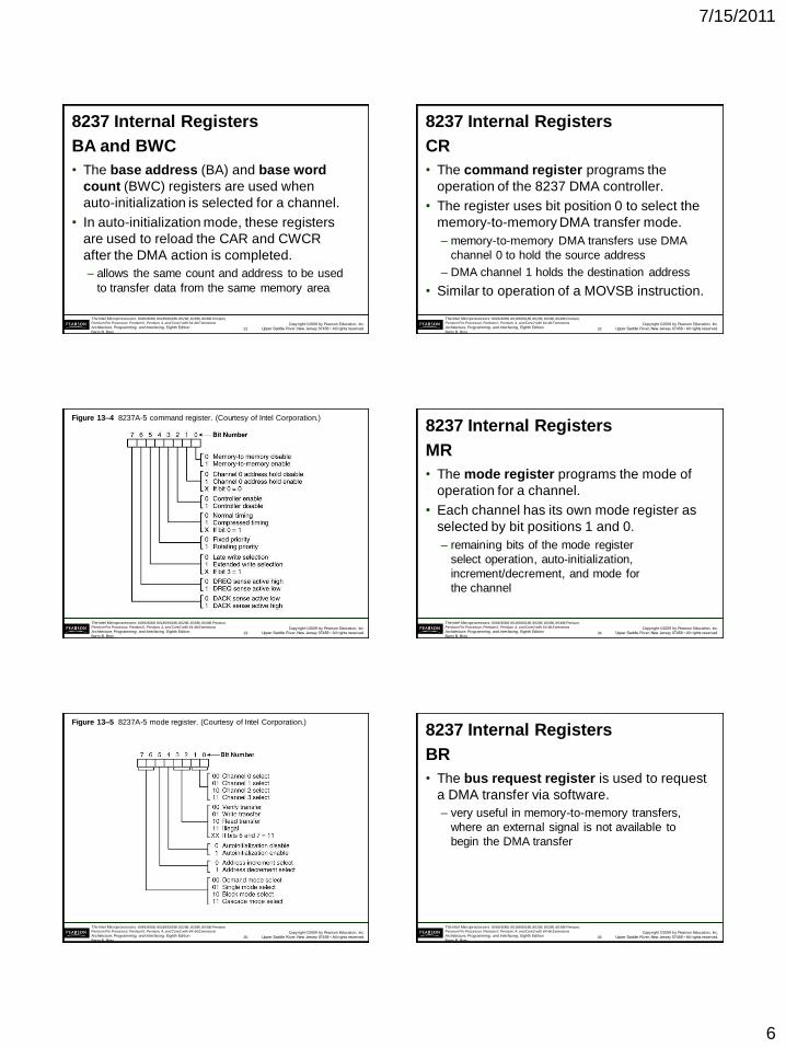
Figure 13–4 8237A-5 command register. (Courtesy of Intel Corporation.)
33
Copyright ©2009 by Pearson Education, Inc.
Upper Saddle River, New Jersey 07458 • All rights reserved.
The Intel Microprocessors: 8086/8088, 80186/80188, 80286, 80386, 80486 Pentium,
Pentium Pro Processor, Pentium II, Pentium, 4, and Core2 with 64-bit Extensions
Architecture, Programming, and Interfacing, Eighth Edition
Barry B. Brey
8237 Internal Registers
MR
• The mode register programs the mode of
operation for a channel.
• Each channel has its own mode register as
selected by bit positions 1 and 0.
– remaining bits of the mode register
select operation, auto-initialization,
increment/decrement, and mode for
the channel
34
Copyright ©2009 by Pearson Education, Inc.
Upper Saddle River, New Jersey 07458 • All rights reserved.
The Intel Microprocessors: 8086/8088, 80186/80188, 80286, 80386, 80486 Pentium,
Pentium Pro Processor, Pentium II, Pentium, 4, and Core2 with 64-bit Extensions
Architecture, Programming, and Interfacing, Eighth Edition
Barry B. Brey
Figure 13–5 8237A-5 mode register. (Courtesy of Intel Corporation.)
35
Copyright ©2009 by Pearson Education, Inc.
Upper Saddle River, New Jersey 07458 • All rights reserved.
The Intel Microprocessors: 8086/8088, 80186/80188, 80286, 80386, 80486 Pentium,
Pentium Pro Processor, Pentium II, Pentium, 4, and Core2 with 64-bit Extensions
Architecture, Programming, and Interfacing, Eighth Edition
Barry B. Brey
8237 Internal Registers
BR
• The bus request register is used to request
a DMA transfer via software.
– very useful in memory-to-memory transfers,
where an external signal is not available to
begin the DMA transfer
36
7/15/2011
7
Copyright ©2009 by Pearson Education, Inc.
Upper Saddle River, New Jersey 07458 • All rights reserved.
The Intel Microprocessors: 8086/8088, 80186/80188, 80286, 80386, 80486 Pentium,
Pentium Pro Processor, Pentium II, Pentium, 4, and Core2 with 64-bit Extensions
Architecture, Programming, and Interfacing, Eighth Edition
Barry B. Brey
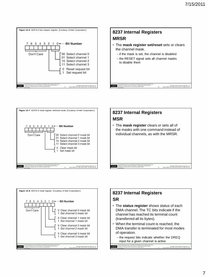
Figure 13–6 8237A-5 bus request register. (Courtesy of Intel Corporation.)
37
Copyright ©2009 by Pearson Education, Inc.
Upper Saddle River, New Jersey 07458 • All rights reserved.
The Intel Microprocessors: 8086/8088, 80186/80188, 80286, 80386, 80486 Pentium,
Pentium Pro Processor, Pentium II, Pentium, 4, and Core2 with 64-bit Extensions
Architecture, Programming, and Interfacing, Eighth Edition
Barry B. Brey
8237 Internal Registers
MRSR
• The mask register set/reset sets or clears
the channel mask.
– if the mask is set, the channel is disabled
– the RESET signal sets all channel masks
to disable them
38
Copyright ©2009 by Pearson Education, Inc.
Upper Saddle River, New Jersey 07458 • All rights reserved.
The Intel Microprocessors: 8086/8088, 80186/80188, 80286, 80386, 80486 Pentium,
Pentium Pro Processor, Pentium II, Pentium, 4, and Core2 with 64-bit Extensions
Architecture, Programming, and Interfacing, Eighth Edition
Barry B. Brey
Figure 13–7 8237A-5 mask register set/reset mode. (Courtesy of Intel Corporation.)
39
Copyright ©2009 by Pearson Education, Inc.
Upper Saddle River, New Jersey 07458 • All rights reserved.
The Intel Microprocessors: 8086/8088, 80186/80188, 80286, 80386, 80486 Pentium,
Pentium Pro Processor, Pentium II, Pentium, 4, and Core2 with 64-bit Extensions
Architecture, Programming, and Interfacing, Eighth Edition
Barry B. Brey
8237 Internal Registers
MSR
• The mask register clears or sets all of
the masks with one command instead of
individual channels, as with the MRSR.
40
Copyright ©2009 by Pearson Education, Inc.
Upper Saddle River, New Jersey 07458 • All rights reserved.
The Intel Microprocessors: 8086/8088, 80186/80188, 80286, 80386, 80486 Pentium,
Pentium Pro Processor, Pentium II, Pentium, 4, and Core2 with 64-bit Extensions
Architecture, Programming, and Interfacing, Eighth Edition
Barry B. Brey
Figure 13–8 8237A-5 mask register. (Courtesy of Intel Corporation.)
41
Copyright ©2009 by Pearson Education, Inc.
Upper Saddle River, New Jersey 07458 • All rights reserved.
The Intel Microprocessors: 8086/8088, 80186/80188, 80286, 80386, 80486 Pentium,
Pentium Pro Processor, Pentium II, Pentium, 4, and Core2 with 64-bit Extensions
Architecture, Programming, and Interfacing, Eighth Edition
Barry B. Brey
8237 Internal Registers
SR
• The status register shows status of each
DMA channel. The TC bits indicate if the
channel has reached its terminal count
(transferred all its bytes).
• When the terminal count is reached, the
DMA transfer is terminated for most modes
of operation.
– the request bits indicate whether the DREQ
input for a given channel is active
42
7/15/2011
8
Copyright ©2009 by Pearson Education, Inc.
Upper Saddle River, New Jersey 07458 • All rights reserved.
The Intel Microprocessors: 8086/8088, 80186/80188, 80286, 80386, 80486 Pentium,
Pentium Pro Processor, Pentium II, Pentium, 4, and Core2 with 64-bit Extensions
Architecture, Programming, and Interfacing, Eighth Edition
Barry B. Brey
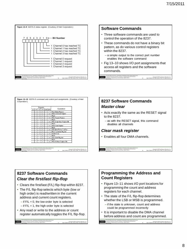
Figure 13–9 8237A-5 status register. (Courtesy of Intel Corporation.)
43
Copyright ©2009 by Pearson Education, Inc.
Upper Saddle River, New Jersey 07458 • All rights reserved.
The Intel Microprocessors: 8086/8088, 80186/80188, 80286, 80386, 80486 Pentium,
Pentium Pro Processor, Pentium II, Pentium, 4, and Core2 with 64-bit Extensions
Architecture, Programming, and Interfacing, Eighth Edition
Barry B. Brey
Software Commands
• Three software commands are used to
control the operation of the 8237.
• These commands do not have a binary bit
pattern, as do various control registers
within the 8237.
– a simple output to the correct port number
enables the software command
• Fig 13–10 shows I/O port assignments that
access all registers and the software
commands.
44
Copyright ©2009 by Pearson Education, Inc.
Upper Saddle River, New Jersey 07458 • All rights reserved.
The Intel Microprocessors: 8086/8088, 80186/80188, 80286, 80386, 80486 Pentium,
Pentium Pro Processor, Pentium II, Pentium, 4, and Core2 with 64-bit Extensions
Architecture, Programming, and Interfacing, Eighth Edition
Barry B. Brey
Figure 13–10 8237A-5 command and control port assignments. (Courtesy of Intel
Corporation.)
45
Copyright ©2009 by Pearson Education, Inc.
Upper Saddle River, New Jersey 07458 • All rights reserved.
The Intel Microprocessors: 8086/8088, 80186/80188, 80286, 80386, 80486 Pentium,
Pentium Pro Processor, Pentium II, Pentium, 4, and Core2 with 64-bit Extensions
Architecture, Programming, and Interfacing, Eighth Edition
Barry B. Brey
8237 Software Commands
Master clear
• Acts exactly the same as the RESET signal
to the 8237.
– as with the RESET signal, this command
disables all channels
Clear mask register
• Enables all four DMA channels.
46
Copyright ©2009 by Pearson Education, Inc.
Upper Saddle River, New Jersey 07458 • All rights reserved.
The Intel Microprocessors: 8086/8088, 80186/80188, 80286, 80386, 80486 Pentium,
Pentium Pro Processor, Pentium II, Pentium, 4, and Core2 with 64-bit Extensions
Architecture, Programming, and Interfacing, Eighth Edition
Barry B. Brey
8237 Software Commands
Clear the first/last flip-flop
• Clears the first/last (F/L) flip-flop within 8237.
• The F/L flip-flop selects which byte (low or
high order) is read/written in the current
address and current count registers.
– if F/L = 0, the low-order byte is selected
– if F/L = 1, the high-order byte is selected
• Any read or write to the address or count
register automatically toggles the F/L flip-flop.
47
Copyright ©2009 by Pearson Education, Inc.
Upper Saddle River, New Jersey 07458 • All rights reserved.
The Intel Microprocessors: 8086/8088, 80186/80188, 80286, 80386, 80486 Pentium,
Pentium Pro Processor, Pentium II, Pentium, 4, and Core2 with 64-bit Extensions
Architecture, Programming, and Interfacing, Eighth Edition
Barry B. Brey
Programming the Address and
Count Registers
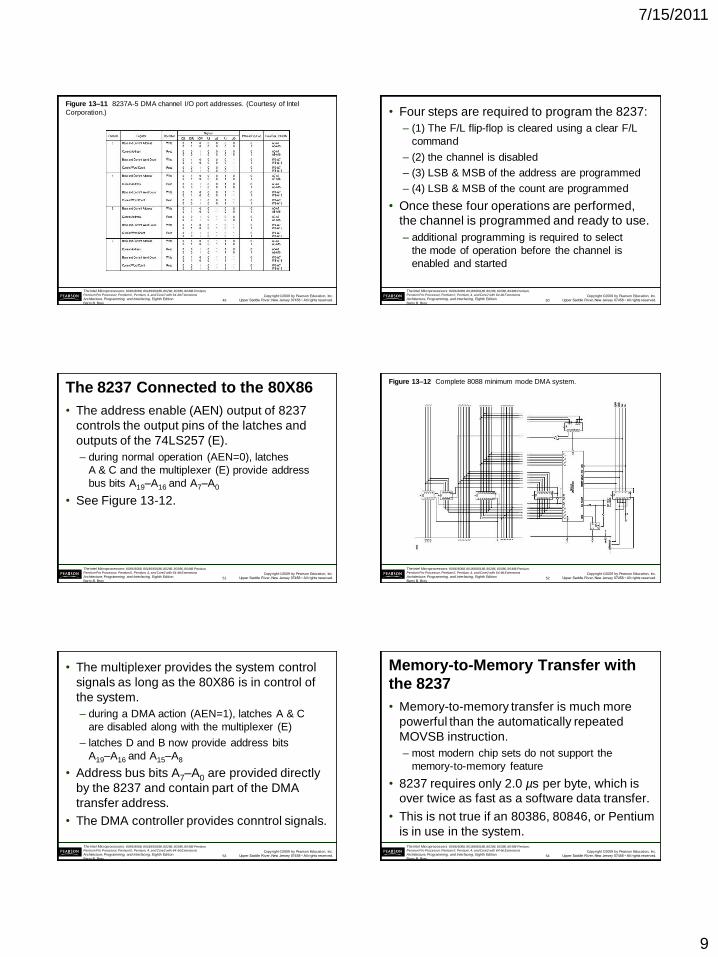
• Figure 13–11 shows I/O port locations for
programming the count and address
registers for each channel.
• The state of the F/L flip-flop determines
whether the LSB or MSB is programmed.
– if the state is unknown, count and address
could be programmed incorrectly
• It is important to disable the DMA channel
before address and count are programmed.
48
7/15/2011
9
Copyright ©2009 by Pearson Education, Inc.
Upper Saddle River, New Jersey 07458 • All rights reserved.
The Intel Microprocessors: 8086/8088, 80186/80188, 80286, 80386, 80486 Pentium,
Pentium Pro Processor, Pentium II, Pentium, 4, and Core2 with 64-bit Extensions
Architecture, Programming, and Interfacing, Eighth Edition
Barry B. Brey
Figure 13–11 8237A-5 DMA channel I/O port addresses. (Courtesy of Intel
Corporation.)
49
Copyright ©2009 by Pearson Education, Inc.
Upper Saddle River, New Jersey 07458 • All rights reserved.
The Intel Microprocessors: 8086/8088, 80186/80188, 80286, 80386, 80486 Pentium,
Pentium Pro Processor, Pentium II, Pentium, 4, and Core2 with 64-bit Extensions
Architecture, Programming, and Interfacing, Eighth Edition
Barry B. Brey
• Four steps are required to program the 8237:
– (1) The F/L flip-flop is cleared using a clear F/L
command
– (2) the channel is disabled
– (3) LSB & MSB of the address are programmed
– (4) LSB & MSB of the count are programmed
• Once these four operations are performed,
the channel is programmed and ready to use.
– additional programming is required to select
the mode of operation before the channel is
enabled and started
50
Copyright ©2009 by Pearson Education, Inc.
Upper Saddle River, New Jersey 07458 • All rights reserved.
The Intel Microprocessors: 8086/8088, 80186/80188, 80286, 80386, 80486 Pentium,
Pentium Pro Processor, Pentium II, Pentium, 4, and Core2 with 64-bit Extensions
Architecture, Programming, and Interfacing, Eighth Edition
Barry B. Brey
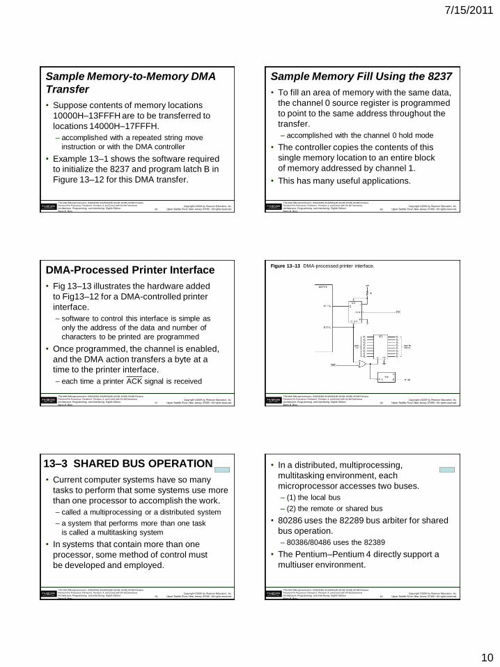
The 8237 Connected to the 80X86
• The address enable (AEN) output of 8237
controls the output pins of the latches and
outputs of the 74LS257 (E).
– during normal operation (AEN=0), latches
A & C and the multiplexer (E) provide address
bus bits A19–A16 and A7–A0
• See Figure 13-12.
51
Copyright ©2009 by Pearson Education, Inc.
Upper Saddle River, New Jersey 07458 • All rights reserved.
The Intel Microprocessors: 8086/8088, 80186/80188, 80286, 80386, 80486 Pentium,
Pentium Pro Processor, Pentium II, Pentium, 4, and Core2 with 64-bit Extensions
Architecture, Programming, and Interfacing, Eighth Edition
Barry B. Brey
Figure 13–12 Complete 8088 minimum mode DMA system.
52
Copyright ©2009 by Pearson Education, Inc.
Upper Saddle River, New Jersey 07458 • All rights reserved.
The Intel Microprocessors: 8086/8088, 80186/80188, 80286, 80386, 80486 Pentium,
Pentium Pro Processor, Pentium II, Pentium, 4, and Core2 with 64-bit Extensions
Architecture, Programming, and Interfacing, Eighth Edition
Barry B. Brey
• The multiplexer provides the system control
signals as long as the 80X86 is in control of
the system.
– during a DMA action (AEN=1), latches A & C
are disabled along with the multiplexer (E)
– latches D and B now provide address bits
A19–A16 and A15–A8
• Address bus bits A7–A0 are provided directly
by the 8237 and contain part of the DMA
transfer address.
• The DMA controller provides conntrol signals.
53
Copyright ©2009 by Pearson Education, Inc.
Upper Saddle River, New Jersey 07458 • All rights reserved.
The Intel Microprocessors: 8086/8088, 80186/80188, 80286, 80386, 80486 Pentium,
Pentium Pro Processor, Pentium II, Pentium, 4, and Core2 with 64-bit Extensions
Architecture, Programming, and Interfacing, Eighth Edition
Barry B. Brey
Memory-to-Memory Transfer with
the 8237
• Memory-to-memory transfer is much more
powerful than the automatically repeated
MOVSB instruction.
– most modern chip sets do not support the
memory-to-memory feature
• 8237 requires only 2.0 µs per byte, which is
over twice as fast as a software data transfer.
• This is not true if an 80386, 80846, or Pentium
is in use in the system.
54
7/15/2011
10
Copyright ©2009 by Pearson Education, Inc.
Upper Saddle River, New Jersey 07458 • All rights reserved.
The Intel Microprocessors: 8086/8088, 80186/80188, 80286, 80386, 80486 Pentium,
Pentium Pro Processor, Pentium II, Pentium, 4, and Core2 with 64-bit Extensions
Architecture, Programming, and Interfacing, Eighth Edition
Barry B. Brey
Sample Memory-to-Memory DMA
Transfer
• Suppose contents of memory locations
10000H–13FFFH are to be transferred to
locations 14000H–17FFFH.
– accomplished with a repeated string move
instruction or with the DMA controller
• Example 13–1 shows the software required
to initialize the 8237 and program latch B in
Figure 13–12 for this DMA transfer.
55
Copyright ©2009 by Pearson Education, Inc.
Upper Saddle River, New Jersey 07458 • All rights reserved.
The Intel Microprocessors: 8086/8088, 80186/80188, 80286, 80386, 80486 Pentium,
Pentium Pro Processor, Pentium II, Pentium, 4, and Core2 with 64-bit Extensions
Architecture, Programming, and Interfacing, Eighth Edition
Barry B. Brey
Sample Memory Fill Using the 8237
• To fill an area of memory with the same data,
the channel 0 source register is programmed
to point to the same address throughout the
transfer.
– accomplished with the channel 0 hold mode
• The controller copies the contents of this
single memory location to an entire block
of memory addressed by channel 1.
• This has many useful applications.
56
Copyright ©2009 by Pearson Education, Inc.
Upper Saddle River, New Jersey 07458 • All rights reserved.
The Intel Microprocessors: 8086/8088, 80186/80188, 80286, 80386, 80486 Pentium,
Pentium Pro Processor, Pentium II, Pentium, 4, and Core2 with 64-bit Extensions
Architecture, Programming, and Interfacing, Eighth Edition
Barry B. Brey
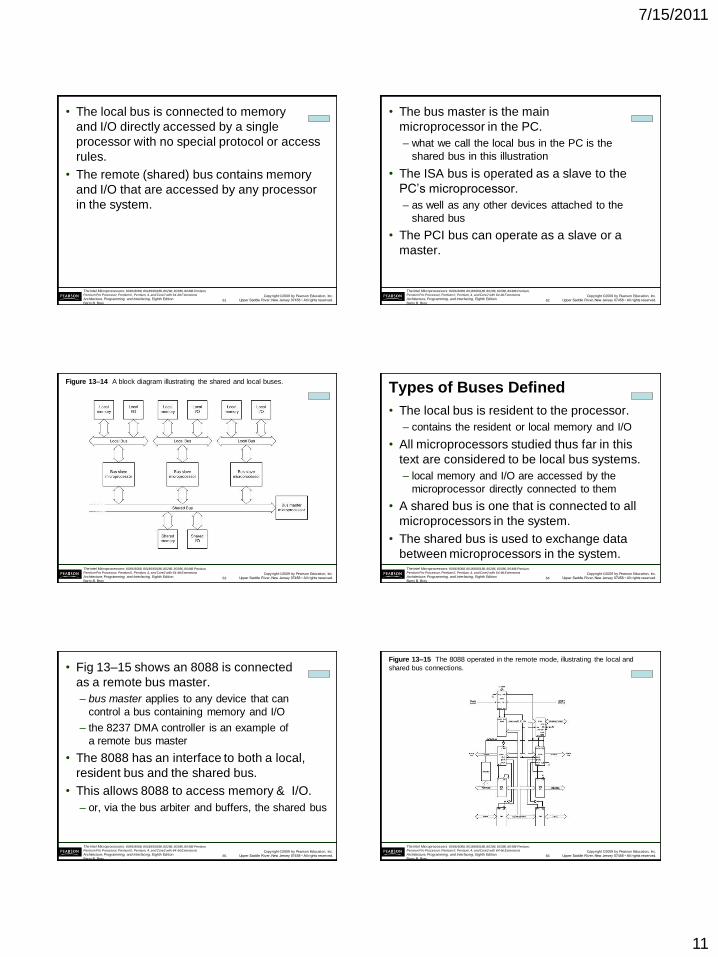
DMA-Processed Printer Interface
• Fig 13–13 illustrates the hardware added
to Fig13–12 for a DMA-controlled printer
interface.
– software to control this interface is simple as
only the address of the data and number of
characters to be printed are programmed
• Once programmed, the channel is enabled,
and the DMA action transfers a byte at a
time to the printer interface.
– each time a printer ACK signal is received
57
Copyright ©2009 by Pearson Education, Inc.
Upper Saddle River, New Jersey 07458 • All rights reserved.
The Intel Microprocessors: 8086/8088, 80186/80188, 80286, 80386, 80486 Pentium,
Pentium Pro Processor, Pentium II, Pentium, 4, and Core2 with 64-bit Extensions
Architecture, Programming, and Interfacing, Eighth Edition
Barry B. Brey
Figure 13–13 DMA-processed printer interface.
58
Copyright ©2009 by Pearson Education, Inc.
Upper Saddle River, New Jersey 07458 • All rights reserved.
The Intel Microprocessors: 8086/8088, 80186/80188, 80286, 80386, 80486 Pentium,
Pentium Pro Processor, Pentium II, Pentium, 4, and Core2 with 64-bit Extensions
Architecture, Programming, and Interfacing, Eighth Edition
Barry B. Brey
13–3 SHARED BUS OPERATION
• Current computer systems have so many
tasks to perform that some systems use more
than one processor to accomplish the work.
– called a multiprocessing or a distributed system
– a system that performs more than one task
is called a multitasking system
• In systems that contain more than one
processor, some method of control must
be developed and employed.
59
Copyright ©2009 by Pearson Education, Inc.
Upper Saddle River, New Jersey 07458 • All rights reserved.
The Intel Microprocessors: 8086/8088, 80186/80188, 80286, 80386, 80486 Pentium,
Pentium Pro Processor, Pentium II, Pentium, 4, and Core2 with 64-bit Extensions
Architecture, Programming, and Interfacing, Eighth Edition
Barry B. Brey
• In a distributed, multiprocessing,
multitasking environment, each
microprocessor accesses two buses.
– (1) the local bus
– (2) the remote or shared bus
• 80286 uses the 82289 bus arbiter for shared
bus operation.
– 80386/80486 uses the 82389
• The Pentium–Pentium 4 directly support a
multiuser environment.
60
7/15/2011
11
Copyright ©2009 by Pearson Education, Inc.
Upper Saddle River, New Jersey 07458 • All rights reserved.
The Intel Microprocessors: 8086/8088, 80186/80188, 80286, 80386, 80486 Pentium,
Pentium Pro Processor, Pentium II, Pentium, 4, and Core2 with 64-bit Extensions
Architecture, Programming, and Interfacing, Eighth Edition
Barry B. Brey
• The local bus is connected to memory
and I/O directly accessed by a single
processor with no special protocol or access
rules.
• The remote (shared) bus contains memory
and I/O that are accessed by any processor
in the system.
61
Copyright ©2009 by Pearson Education, Inc.
Upper Saddle River, New Jersey 07458 • All rights reserved.
The Intel Microprocessors: 8086/8088, 80186/80188, 80286, 80386, 80486 Pentium,
Pentium Pro Processor, Pentium II, Pentium, 4, and Core2 with 64-bit Extensions
Architecture, Programming, and Interfacing, Eighth Edition
Barry B. Brey
• The bus master is the main
microprocessor in the PC.
– what we call the local bus in the PC is the
shared bus in this illustration
• The ISA bus is operated as a slave to the
PC’s microprocessor.
– as well as any other devices attached to the
shared bus
• The PCI bus can operate as a slave or a
master.
62
Copyright ©2009 by Pearson Education, Inc.
Upper Saddle River, New Jersey 07458 • All rights reserved.
The Intel Microprocessors: 8086/8088, 80186/80188, 80286, 80386, 80486 Pentium,
Pentium Pro Processor, Pentium II, Pentium, 4, and Core2 with 64-bit Extensions
Architecture, Programming, and Interfacing, Eighth Edition
Barry B. Brey
Figure 13–14 A block diagram illustrating the shared and local buses.
63
Copyright ©2009 by Pearson Education, Inc.
Upper Saddle River, New Jersey 07458 • All rights reserved.
The Intel Microprocessors: 8086/8088, 80186/80188, 80286, 80386, 80486 Pentium,
Pentium Pro Processor, Pentium II, Pentium, 4, and Core2 with 64-bit Extensions
Architecture, Programming, and Interfacing, Eighth Edition
Barry B. Brey
Types of Buses Defined
• The local bus is resident to the processor.
– contains the resident or local memory and I/O
• All microprocessors studied thus far in this
text are considered to be local bus systems.
– local memory and I/O are accessed by the
microprocessor directly connected to them
• A shared bus is one that is connected to all
microprocessors in the system.
• The shared bus is used to exchange data
between microprocessors in the system.
64
Copyright ©2009 by Pearson Education, Inc.
Upper Saddle River, New Jersey 07458 • All rights reserved.
The Intel Microprocessors: 8086/8088, 80186/80188, 80286, 80386, 80486 Pentium,
Pentium Pro Processor, Pentium II, Pentium, 4, and Core2 with 64-bit Extensions
Architecture, Programming, and Interfacing, Eighth Edition
Barry B. Brey
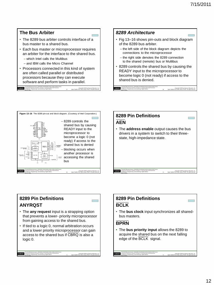
• Fig 13–15 shows an 8088 is connected
as a remote bus master.
– bus master applies to any device that can
control a bus containing memory and I/O
– the 8237 DMA controller is an example of
a remote bus master
• The 8088 has an interface to both a local,
resident bus and the shared bus.
• This allows 8088 to access memory & I/O.
– or, via the bus arbiter and buffers, the shared bus
65
Copyright ©2009 by Pearson Education, Inc.
Upper Saddle River, New Jersey 07458 • All rights reserved.
The Intel Microprocessors: 8086/8088, 80186/80188, 80286, 80386, 80486 Pentium,
Pentium Pro Processor, Pentium II, Pentium, 4, and Core2 with 64-bit Extensions
Architecture, Programming, and Interfacing, Eighth Edition
Barry B. Brey
Figure 13–15 The 8088 operated in the remote mode, illustrating the local and
shared bus connections.
66
7/15/2011
12
Copyright ©2009 by Pearson Education, Inc.
Upper Saddle River, New Jersey 07458 • All rights reserved.
The Intel Microprocessors: 8086/8088, 80186/80188, 80286, 80386, 80486 Pentium,
Pentium Pro Processor, Pentium II, Pentium, 4, and Core2 with 64-bit Extensions
Architecture, Programming, and Interfacing, Eighth Edition
Barry B. Brey
The Bus Arbiter
• The 8289 bus arbiter controls interface of a
bus master to a shared bus.
• Each bus master or microprocessor requires
an arbiter for the interface to the shared bus.
– which Intel calls the Multibus
– and IBM calls the Micro Channel
• Processors connected in this kind of system
are often called parallel or distributed
processors because they can execute
software and perform tasks in parallel.
67
Copyright ©2009 by Pearson Education, Inc.
Upper Saddle River, New Jersey 07458 • All rights reserved.
The Intel Microprocessors: 8086/8088, 80186/80188, 80286, 80386, 80486 Pentium,
Pentium Pro Processor, Pentium II, Pentium, 4, and Core2 with 64-bit Extensions
Architecture, Programming, and Interfacing, Eighth Edition
Barry B. Brey
8289 Architecture
• Fig 13–16 shows pin-outs and block diagram
of the 8289 bus arbiter.
– the left side of the block diagram depicts the
connections to the microprocessor
– the right side denotes the 8289 connection
to the shared (remote) bus or Multibus
• 8289 controls the shared bus by causing the
READY input to the microprocessor to
become logic 0 (not ready) if access to the
shared bus is denied.
68
Copyright ©2009 by Pearson Education, Inc.
Upper Saddle River, New Jersey 07458 • All rights reserved.
The Intel Microprocessors: 8086/8088, 80186/80188, 80286, 80386, 80486 Pentium,
Pentium Pro Processor, Pentium II, Pentium, 4, and Core2 with 64-bit Extensions
Architecture, Programming, and Interfacing, Eighth Edition
Barry B. Brey
Figure 13–16 The 8289 pin-out and block diagram. (Courtesy of Intel Corporation.)
– 8289 controls the
shared bus by causing
READY input to the
microprocessor to
become a logic 0 (not
ready) if access to the
shared bus is denied
– blocking occurs when
another processor is
accessing the shared
bus
69
Copyright ©2009 by Pearson Education, Inc.
Upper Saddle River, New Jersey 07458 • All rights reserved.
The Intel Microprocessors: 8086/8088, 80186/80188, 80286, 80386, 80486 Pentium,
Pentium Pro Processor, Pentium II, Pentium, 4, and Core2 with 64-bit Extensions
Architecture, Programming, and Interfacing, Eighth Edition
Barry B. Brey
8289 Pin Definitions
AEN
• The address enable output causes the bus
drivers in a system to switch to their three-
state, high-impedance state.
70
Copyright ©2009 by Pearson Education, Inc.
Upper Saddle River, New Jersey 07458 • All rights reserved.
The Intel Microprocessors: 8086/8088, 80186/80188, 80286, 80386, 80486 Pentium,
Pentium Pro Processor, Pentium II, Pentium, 4, and Core2 with 64-bit Extensions
Architecture, Programming, and Interfacing, Eighth Edition
Barry B. Brey
8289 Pin Definitions
ANYRQST
• The any request input is a strapping option
that prevents a lower- priority microprocessor
from gaining access to the shared bus.
• If tied to a logic 0, normal arbitration occurs
and a lower priority microprocessor can gain
access to the shared bus if CBRQ is also a
logic 0.
71
Copyright ©2009 by Pearson Education, Inc.
Upper Saddle River, New Jersey 07458 • All rights reserved.
The Intel Microprocessors: 8086/8088, 80186/80188, 80286, 80386, 80486 Pentium,
Pentium Pro Processor, Pentium II, Pentium, 4, and Core2 with 64-bit Extensions
Architecture, Programming, and Interfacing, Eighth Edition
Barry B. Brey
8289 Pin Definitions
BCLK
• The bus clock input synchronizes all shared-
bus masters.
BPRN
• The bus priority input allows the 8289 to
acquire the shared bus on the next falling
edge of the BCLK signal.
72
7/15/2011
13
Copyright ©2009 by Pearson Education, Inc.
Upper Saddle River, New Jersey 07458 • All rights reserved.
The Intel Microprocessors: 8086/8088, 80186/80188, 80286, 80386, 80486 Pentium,
Pentium Pro Processor, Pentium II, Pentium, 4, and Core2 with 64-bit Extensions
Architecture, Programming, and Interfacing, Eighth Edition
Barry B. Brey
8289 Pin Definitions
BPRO
• The bus priority output is a signal that is
used to resolve priority in a system that
contains multiple bus masters.
BREQ
• The bus request output is used to request
access to the shared bus.
73
Copyright ©2009 by Pearson Education, Inc.
Upper Saddle River, New Jersey 07458 • All rights reserved.
The Intel Microprocessors: 8086/8088, 80186/80188, 80286, 80386, 80486 Pentium,
Pentium Pro Processor, Pentium II, Pentium, 4, and Core2 with 64-bit Extensions
Architecture, Programming, and Interfacing, Eighth Edition
Barry B. Brey
8289 Pin Definitions
BUSY
• The busy input/output indicates, as an
output, that an 8289 has acquired the
shared bus.
• As an input, BUSY is used to detect that
another 8289 has acquired the shared bus.
74
Copyright ©2009 by Pearson Education, Inc.
Upper Saddle River, New Jersey 07458 • All rights reserved.
The Intel Microprocessors: 8086/8088, 80186/80188, 80286, 80386, 80486 Pentium,
Pentium Pro Processor, Pentium II, Pentium, 4, and Core2 with 64-bit Extensions
Architecture, Programming, and Interfacing, Eighth Edition
Barry B. Brey
8289 Pin Definitions
CBRQ
• The common bus request input/output is
used when a lower priority microprocessor
is asking for the use of the shared bus.
• As an output, CBRQ becomes logic 0 when
the 8289 requests the shared bus and
remains low until the 8289 obtains access
to the shared bus.
75
Copyright ©2009 by Pearson Education, Inc.
Upper Saddle River, New Jersey 07458 • All rights reserved.
The Intel Microprocessors: 8086/8088, 80186/80188, 80286, 80386, 80486 Pentium,
Pentium Pro Processor, Pentium II, Pentium, 4, and Core2 with 64-bit Extensions
Architecture, Programming, and Interfacing, Eighth Edition
Barry B. Brey
• The common request lock input prevents
8289 from surrendering the shared bus to
any 8289 in the system. This signal functions
in conjunction with the CBRQ pin.
8289 Pin Definitions
CLK
• The clock input is generated by the 8284A
clock generator and provides the internal
timing source to the 8289.
CRQLCK
76
Copyright ©2009 by Pearson Education, Inc.
Upper Saddle River, New Jersey 07458 • All rights reserved.
The Intel Microprocessors: 8086/8088, 80186/80188, 80286, 80386, 80486 Pentium,
Pentium Pro Processor, Pentium II, Pentium, 4, and Core2 with 64-bit Extensions
Architecture, Programming, and Interfacing, Eighth Edition
Barry B. Brey
• The I/O bus input selects whether 8289
operates in a shared-bus system (if selected
by RESB) with I/O (IOB=0) or with memory
and I/O (IOB=1).
8289 Pin Definitions
CLK
• The initialization input resets 8289
– normally connected to the system RESET signal
IOB
77
Copyright ©2009 by Pearson Education, Inc.
Upper Saddle River, New Jersey 07458 • All rights reserved.
The Intel Microprocessors: 8086/8088, 80186/80188, 80286, 80386, 80486 Pentium,
Pentium Pro Processor, Pentium II, Pentium, 4, and Core2 with 64-bit Extensions
Architecture, Programming, and Interfacing, Eighth Edition
Barry B. Brey
8289 Pin Definitions
RESB
• The resident-bus input is a strapping
connection allowing 8289 to operate in
systems that have either a shared-bus or
resident-bus system.
– if RESB is a logic 1, 8289 is configured as a
shared-bus master
– if RESB is a logic 0, as a local-bus master
• As a shared-bus master, access is requested
through the SYSB/RESB input pin.
78
7/15/2011
14
Copyright ©2009 by Pearson Education, Inc.
Upper Saddle River, New Jersey 07458 • All rights reserved.
The Intel Microprocessors: 8086/8088, 80186/80188, 80286, 80386, 80486 Pentium,
Pentium Pro Processor, Pentium II, Pentium, 4, and Core2 with 64-bit Extensions
Architecture, Programming, and Interfacing, Eighth Edition
Barry B. Brey
8289 Pin Definitions
LOCK
• The lock input prevents the 8289 from
allowing any other microprocessor from
gaining access to the shared bus.
• An 8086/8088 instruction that contains a
LOCK prefix will prevent other processors
from accessing the shared bus.
79
Copyright ©2009 by Pearson Education, Inc.
Upper Saddle River, New Jersey 07458 • All rights reserved.
The Intel Microprocessors: 8086/8088, 80186/80188, 80286, 80386, 80486 Pentium,
Pentium Pro Processor, Pentium II, Pentium, 4, and Core2 with 64-bit Extensions
Architecture, Programming, and Interfacing, Eighth Edition
Barry B. Brey
8289 Pin Definitions
S0, S1, and S2
• The status inputs initiate shared-bus requests
and surrenders. These pins connect to the
8288 system bus controller status pins.
SYSB/RESB
• The system bus/resident bus input selects
the shared-bus system when placed at logic 1
or resident local bus when placed at logic 0.
80
Copyright ©2009 by Pearson Education, Inc.
Upper Saddle River, New Jersey 07458 • All rights reserved.
The Intel Microprocessors: 8086/8088, 80186/80188, 80286, 80386, 80486 Pentium,
Pentium Pro Processor, Pentium II, Pentium, 4, and Core2 with 64-bit Extensions
Architecture, Programming, and Interfacing, Eighth Edition
Barry B. Brey
General 8289 Operation
• 8289 can operate in three basic modes:
– (1) I/O peripheral-bus mode
– (2) resident-bus mode
– (3) single-bus mode
• In the I/O peripheral bus mode, all local bus
devices are treated as I/O, including memory.
– and are accessed by all instructions
• All memory references access the shared bus
and all I/O access the resident-local bus.
81
Copyright ©2009 by Pearson Education, Inc.
Upper Saddle River, New Jersey 07458 • All rights reserved.
The Intel Microprocessors: 8086/8088, 80186/80188, 80286, 80386, 80486 Pentium,
Pentium Pro Processor, Pentium II, Pentium, 4, and Core2 with 64-bit Extensions
Architecture, Programming, and Interfacing, Eighth Edition
Barry B. Brey
System Illustrating Single-Bus
and Resident-Bus Connections
• Single-bus operation interfaces a processor
to a shared bus with both I/O and memory
resources shared by other processors.
• Fig 13–17 illustrates three 8088 processors,
each connected to a shared bus.
• Two of the three microprocessors operate in
the resident-bus mode, while the third
operates in the single-bus mode.
82
Copyright ©2009 by Pearson Education, Inc.
Upper Saddle River, New Jersey 07458 • All rights reserved.
The Intel Microprocessors: 8086/8088, 80186/80188, 80286, 80386, 80486 Pentium,
Pentium Pro Processor, Pentium II, Pentium, 4, and Core2 with 64-bit Extensions
Architecture, Programming, and Interfacing, Eighth Edition
Barry B. Brey
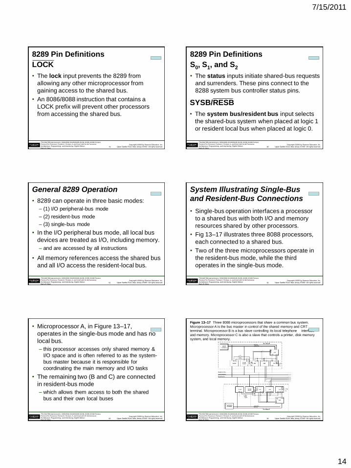
• Microprocessor A, in Figure 13–17,
operates in the single-bus mode and has no
local bus.
– this processor accesses only shared memory &
I/O space and is often referred to as the system-
bus master because it is responsible for
coordinating the main memory and I/O tasks
• The remaining two (B and C) are connected
in resident-bus mode
– which allows them access to both the shared
bus and their own local buses
83
Copyright ©2009 by Pearson Education, Inc.
Upper Saddle River, New Jersey 07458 • All rights reserved.
The Intel Microprocessors: 8086/8088, 80186/80188, 80286, 80386, 80486 Pentium,
Pentium Pro Processor, Pentium II, Pentium, 4, and Core2 with 64-bit Extensions
Architecture, Programming, and Interfacing, Eighth Edition
Barry B. Brey
Figure 13–17 Three 8088 microprocessors that share a common bus system.
Microprocessor A is the bus master in control of the shared memory and CRT
terminal. Microprocessor B is a bus slave controlling its local telephone interface
and memory. Microprocessor C is also a slave that controls a printer, disk memory
system, and local memory.
84
7/15/2011
15
Copyright ©2009 by Pearson Education, Inc.
Upper Saddle River, New Jersey 07458 • All rights reserved.
The Intel Microprocessors: 8086/8088, 80186/80188, 80286, 80386, 80486 Pentium,
Pentium Pro Processor, Pentium II, Pentium, 4, and Core2 with 64-bit Extensions
Architecture, Programming, and Interfacing, Eighth Edition
Barry B. Brey
• Bus master (A) allows the user to operate
with a video terminal that allows execution
of programs and generally controls the
system.
• Microprocessor B handles all telephone
communications and passes this information
to the shared memory in blocks.
• Processor C is used as a print spooler. Its
only task is to print data on the printer.
– when the bus master requires printed output,
it transfers the task to microprocessor C
• These tasks all execute simultaneously.
85
Copyright ©2009 by Pearson Education, Inc.
Upper Saddle River, New Jersey 07458 • All rights reserved.
The Intel Microprocessors: 8086/8088, 80186/80188, 80286, 80386, 80486 Pentium,
Pentium Pro Processor, Pentium II, Pentium, 4, and Core2 with 64-bit Extensions
Architecture, Programming, and Interfacing, Eighth Edition
Barry B. Brey
• There is no limit to the number of
processors connected to a system or the
number of tasks performed simultaneously
using this technique.
– the only limit is that introduced by the system
design and the designer’s ingenuity
• Lawrence Livermore Labs in California has
a system that contains 4096 Pentium
microprocessors.
86
Copyright ©2009 by Pearson Education, Inc.
Upper Saddle River, New Jersey 07458 • All rights reserved.
The Intel Microprocessors: 8086/8088, 80186/80188, 80286, 80386, 80486 Pentium,
Pentium Pro Processor, Pentium II, Pentium, 4, and Core2 with 64-bit Extensions
Architecture, Programming, and Interfacing, Eighth Edition
Barry B. Brey
13–4 DISK MEMORY SYSTEMS
• Disk memory is used to store long-term data.
• Many types of disk storage systems are
available and they use magnetic media.
– except optical disk memory that stores data
on a plastic disk
• Optical disk memory is either:
– CD-ROM (compact disk/read only memory)
which read, but never written
– WORM (write once/read mostly), read most of
the time, but can be written once by a laser
87
Copyright ©2009 by Pearson Education, Inc.
Upper Saddle River, New Jersey 07458 • All rights reserved.
The Intel Microprocessors: 8086/8088, 80186/80188, 80286, 80386, 80486 Pentium,
Pentium Pro Processor, Pentium II, Pentium, 4, and Core2 with 64-bit Extensions
Architecture, Programming, and Interfacing, Eighth Edition
Barry B. Brey
• Optical disk memory that can be read and
written many times is becoming available.
– there is still a limitation on the number of write
operations allowed
• The latest optical disk technology is called
DVD (digital-versatile disk).
– also available in high-resolution versions for
video and data storage as Blu-ray (50G) or
HD-DVD (30G)
88
Copyright ©2009 by Pearson Education, Inc.
Upper Saddle River, New Jersey 07458 • All rights reserved.
The Intel Microprocessors: 8086/8088, 80186/80188, 80286, 80386, 80486 Pentium,
Pentium Pro Processor, Pentium II, Pentium, 4, and Core2 with 64-bit Extensions
Architecture, Programming, and Interfacing, Eighth Edition
Barry B. Brey
Floppy Disk Memory
• The floppy, or flexible disk was once the most
common and basic form of disk memory.
– the floppy is beginning to vanish and may
disappear shortly in favor of the USB pen drive
• Floppy disk magnetic recording media have
been made available in three sizes:
– 8 standard
– 51/4 mini-floppy
– 31/2 micro-floppy.
89
Copyright ©2009 by Pearson Education, Inc.
Upper Saddle River, New Jersey 07458 • All rights reserved.
The Intel Microprocessors: 8086/8088, 80186/80188, 80286, 80386, 80486 Pentium,
Pentium Pro Processor, Pentium II, Pentium, 4, and Core2 with 64-bit Extensions
Architecture, Programming, and Interfacing, Eighth Edition
Barry B. Brey
• All disks have several things in common.
• They are all organized so that data are stored
in tracks and sectors.
– a track is a concentric ring of data stored on
the surface of a disk
– a sector is a common subdivision of a track
designed to hold a reasonable amount of data
• In many systems, a sector holds either 512
or 1024 bytes of data.
– size of a sector can vary from 128 bytes to the
length of one entire track
90
7/15/2011
16
Copyright ©2009 by Pearson Education, Inc.
Upper Saddle River, New Jersey 07458 • All rights reserved.
The Intel Microprocessors: 8086/8088, 80186/80188, 80286, 80386, 80486 Pentium,
Pentium Pro Processor, Pentium II, Pentium, 4, and Core2 with 64-bit Extensions
Architecture, Programming, and Interfacing, Eighth Edition
Barry B. Brey
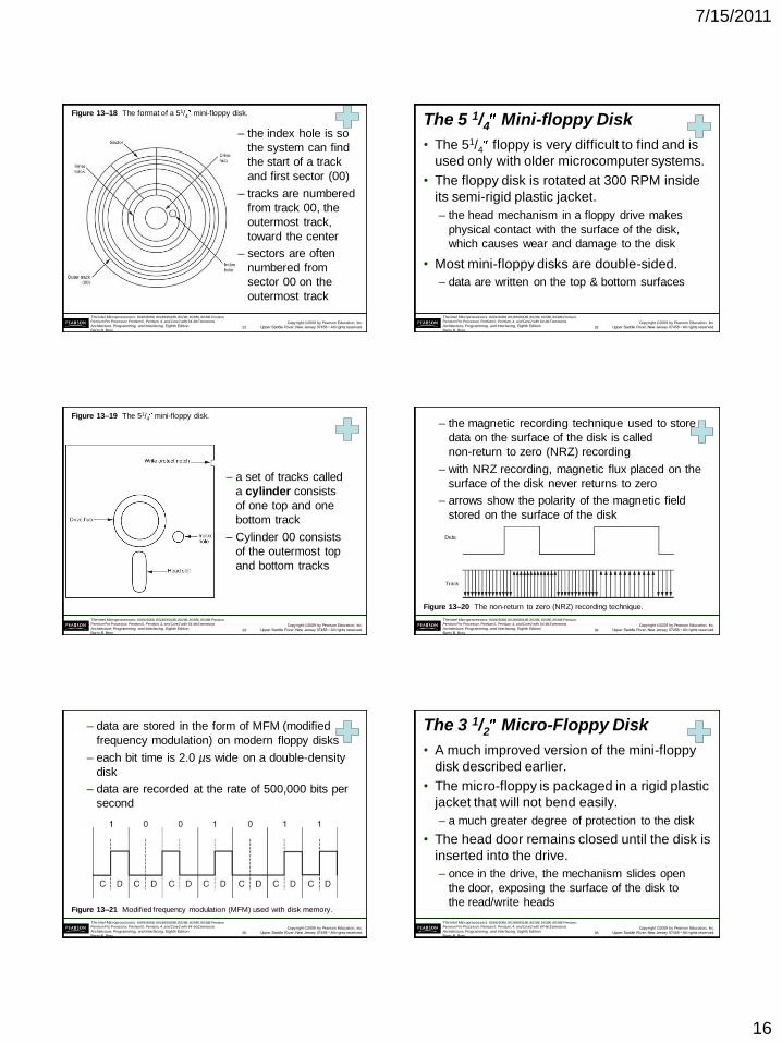
Figure 13–18 The format of a 51/4 mini-floppy disk.
– the index hole is so
the system can find
the start of a track
and first sector (00)
– tracks are numbered
from track 00, the
outermost track,
toward the center
– sectors are often
numbered from
sector 00 on the
outermost track
91
Copyright ©2009 by Pearson Education, Inc.
Upper Saddle River, New Jersey 07458 • All rights reserved.
The Intel Microprocessors: 8086/8088, 80186/80188, 80286, 80386, 80486 Pentium,
Pentium Pro Processor, Pentium II, Pentium, 4, and Core2 with 64-bit Extensions
Architecture, Programming, and Interfacing, Eighth Edition
Barry B. Brey
The 5 1/4 Mini-floppy Disk
• The 51/4 floppy is very difficult to find and is
used only with older microcomputer systems.
• The floppy disk is rotated at 300 RPM inside
its semi-rigid plastic jacket.
– the head mechanism in a floppy drive makes
physical contact with the surface of the disk,
which causes wear and damage to the disk
• Most mini-floppy disks are double-sided.
– data are written on the top & bottom surfaces
92
Copyright ©2009 by Pearson Education, Inc.
Upper Saddle River, New Jersey 07458 • All rights reserved.
The Intel Microprocessors: 8086/8088, 80186/80188, 80286, 80386, 80486 Pentium,
Pentium Pro Processor, Pentium II, Pentium, 4, and Core2 with 64-bit Extensions
Architecture, Programming, and Interfacing, Eighth Edition
Barry B. Brey
Figure 13–19 The 51/4 mini-floppy disk.
– a set of tracks called
a cylinder consists
of one top and one
bottom track
– Cylinder 00 consists
of the outermost top
and bottom tracks
93
Copyright ©2009 by Pearson Education, Inc.
Upper Saddle River, New Jersey 07458 • All rights reserved.
The Intel Microprocessors: 8086/8088, 80186/80188, 80286, 80386, 80486 Pentium,
Pentium Pro Processor, Pentium II, Pentium, 4, and Core2 with 64-bit Extensions
Architecture, Programming, and Interfacing, Eighth Edition
Barry B. Brey
Figure 13–20 The non-return to zero (NRZ) recording technique.
– the magnetic recording technique used to store
data on the surface of the disk is called
non-return to zero (NRZ) recording
– with NRZ recording, magnetic flux placed on the
surface of the disk never returns to zero
– arrows show the polarity of the magnetic field
stored on the surface of the disk
94
Copyright ©2009 by Pearson Education, Inc.
Upper Saddle River, New Jersey 07458 • All rights reserved.
The Intel Microprocessors: 8086/8088, 80186/80188, 80286, 80386, 80486 Pentium,
Pentium Pro Processor, Pentium II, Pentium, 4, and Core2 with 64-bit Extensions
Architecture, Programming, and Interfacing, Eighth Edition
Barry B. Brey
Figure 13–21 Modified frequency modulation (MFM) used with disk memory.
– data are stored in the form of MFM (modified
frequency modulation) on modern floppy disks
– each bit time is 2.0 µs wide on a double-density
disk
– data are recorded at the rate of 500,000 bits per
second
95
Copyright ©2009 by Pearson Education, Inc.
Upper Saddle River, New Jersey 07458 • All rights reserved.
The Intel Microprocessors: 8086/8088, 80186/80188, 80286, 80386, 80486 Pentium,
Pentium Pro Processor, Pentium II, Pentium, 4, and Core2 with 64-bit Extensions
Architecture, Programming, and Interfacing, Eighth Edition
Barry B. Brey
The 3 1/2 Micro-Floppy Disk
• A much improved version of the mini-floppy
disk described earlier.
• The micro-floppy is packaged in a rigid plastic
jacket that will not bend easily.
– a much greater degree of protection to the disk
• The head door remains closed until the disk is
inserted into the drive.
– once in the drive, the mechanism slides open
the door, exposing the surface of the disk to
the read/write heads
96
7/15/2011
17
Copyright ©2009 by Pearson Education, Inc.
Upper Saddle River, New Jersey 07458 • All rights reserved.
The Intel Microprocessors: 8086/8088, 80186/80188, 80286, 80386, 80486 Pentium,
Pentium Pro Processor, Pentium II, Pentium, 4, and Core2 with 64-bit Extensions
Architecture, Programming, and Interfacing, Eighth Edition
Barry B. Brey
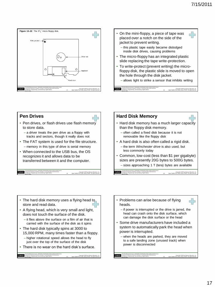
Figure 13–22 The 31/2 micro-floppy disk.
97
Copyright ©2009 by Pearson Education, Inc.
Upper Saddle River, New Jersey 07458 • All rights reserved.
The Intel Microprocessors: 8086/8088, 80186/80188, 80286, 80386, 80486 Pentium,
Pentium Pro Processor, Pentium II, Pentium, 4, and Core2 with 64-bit Extensions
Architecture, Programming, and Interfacing, Eighth Edition
Barry B. Brey
• On the mini-floppy, a piece of tape was
placed over a notch on the side of the
jacket to prevent writing.
– this plastic tape easily became dislodged
inside disk drives, causing problems
• The micro-floppy has an integrated plastic
slide replacing the tape write-protection.
• To write-protect (prevent writing) the micro-
floppy disk, the plastic slide is moved to open
the hole through the disk jacket.
– allows light to strike a sensor that inhibits writing
98
Copyright ©2009 by Pearson Education, Inc.
Upper Saddle River, New Jersey 07458 • All rights reserved.
The Intel Microprocessors: 8086/8088, 80186/80188, 80286, 80386, 80486 Pentium,
Pentium Pro Processor, Pentium II, Pentium, 4, and Core2 with 64-bit Extensions
Architecture, Programming, and Interfacing, Eighth Edition
Barry B. Brey
Pen Drives
• Pen drives, or flash drives use flash memory
to store data.
– a driver treats the pen drive as a floppy with
tracks and sectors, though it really does not
• The FAT system is used for the file structure.
– memory in this type of drive is serial memory
• When connected to the USB bus, the OS
recognizes it and allows data to be
transferred between it and the computer.
99
Copyright ©2009 by Pearson Education, Inc.
Upper Saddle River, New Jersey 07458 • All rights reserved.
The Intel Microprocessors: 8086/8088, 80186/80188, 80286, 80386, 80486 Pentium,
Pentium Pro Processor, Pentium II, Pentium, 4, and Core2 with 64-bit Extensions
Architecture, Programming, and Interfacing, Eighth Edition
Barry B. Brey
Hard Disk Memory
• Hard disk memory has a much larger capacity
than the floppy disk memory.
– often called a fixed disk because it is not
removable like the floppy disk
• A hard disk is also often called a rigid disk.
– the term Winchester drive is also used, but
less commonly today
• Common, low-cost (less than $1 per gigabyte)
sizes are presently 20G bytes to 500G bytes.
– sizes approaching 1 T (tera) bytes are available
100
Copyright ©2009 by Pearson Education, Inc.
Upper Saddle River, New Jersey 07458 • All rights reserved.
The Intel Microprocessors: 8086/8088, 80186/80188, 80286, 80386, 80486 Pentium,
Pentium Pro Processor, Pentium II, Pentium, 4, and Core2 with 64-bit Extensions
Architecture, Programming, and Interfacing, Eighth Edition
Barry B. Brey
• The hard disk memory uses a flying head to
store and read data.
• A flying head, which is very small and light,
does not touch the surface of the disk.
– it flies above the surface on a film of air that is
carried with the surface of the disk as it spins
• The hard disk typically spins at 3000 to
15,000 RPM, many times faster than a floppy.
– higher rotational speed allows the head to fly
just over the top of the surface of the disk
• There is no wear on the hard disk’s surface.
101
Copyright ©2009 by Pearson Education, Inc.
Upper Saddle River, New Jersey 07458 • All rights reserved.
The Intel Microprocessors: 8086/8088, 80186/80188, 80286, 80386, 80486 Pentium,
Pentium Pro Processor, Pentium II, Pentium, 4, and Core2 with 64-bit Extensions
Architecture, Programming, and Interfacing, Eighth Edition
Barry B. Brey
• Problems can arise because of flying
heads.
– if power is interrupted or the drive is jarred, the
head can crash onto the disk surface, which
can damage the disk surface or the head
• Some drive manufacturers have included a
system to automatically park the head when
power is interrupted.
– when the heads are parked, they are moved
to a safe landing zone (unused track) when
power is disconnected
102
7/15/2011
18
Copyright ©2009 by Pearson Education, Inc.
Upper Saddle River, New Jersey 07458 • All rights reserved.
The Intel Microprocessors: 8086/8088, 80186/80188, 80286, 80386, 80486 Pentium,
Pentium Pro Processor, Pentium II, Pentium, 4, and Core2 with 64-bit Extensions
Architecture, Programming, and Interfacing, Eighth Edition
Barry B. Brey
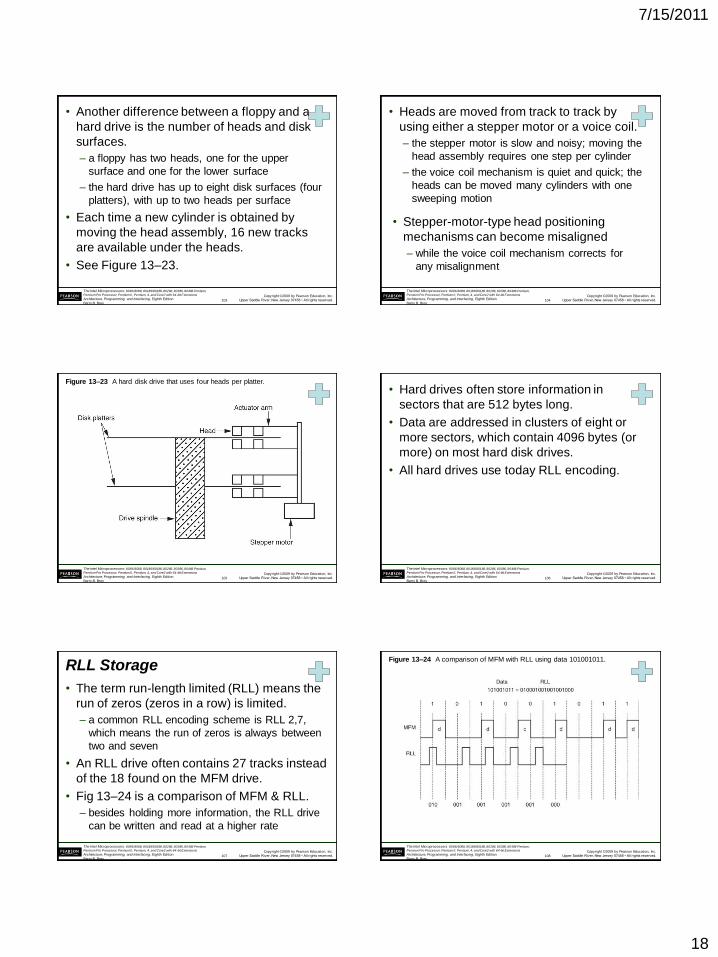
• Another difference between a floppy and a
hard drive is the number of heads and disk
surfaces.
– a floppy has two heads, one for the upper
surface and one for the lower surface
– the hard drive has up to eight disk surfaces (four
platters), with up to two heads per surface
• Each time a new cylinder is obtained by
moving the head assembly, 16 new tracks
are available under the heads.
• See Figure 13–23.
103
Copyright ©2009 by Pearson Education, Inc.
Upper Saddle River, New Jersey 07458 • All rights reserved.
The Intel Microprocessors: 8086/8088, 80186/80188, 80286, 80386, 80486 Pentium,
Pentium Pro Processor, Pentium II, Pentium, 4, and Core2 with 64-bit Extensions
Architecture, Programming, and Interfacing, Eighth Edition
Barry B. Brey
• Heads are moved from track to track by
using either a stepper motor or a voice coil.
– the stepper motor is slow and noisy; moving the
head assembly requires one step per cylinder
– the voice coil mechanism is quiet and quick; the
heads can be moved many cylinders with one
sweeping motion
• Stepper-motor-type head positioning
mechanisms can become misaligned
– while the voice coil mechanism corrects for
any misalignment
104
Copyright ©2009 by Pearson Education, Inc.
Upper Saddle River, New Jersey 07458 • All rights reserved.
The Intel Microprocessors: 8086/8088, 80186/80188, 80286, 80386, 80486 Pentium,
Pentium Pro Processor, Pentium II, Pentium, 4, and Core2 with 64-bit Extensions
Architecture, Programming, and Interfacing, Eighth Edition
Barry B. Brey
Figure 13–23 A hard disk drive that uses four heads per platter.
105
Copyright ©2009 by Pearson Education, Inc.
Upper Saddle River, New Jersey 07458 • All rights reserved.
The Intel Microprocessors: 8086/8088, 80186/80188, 80286, 80386, 80486 Pentium,
Pentium Pro Processor, Pentium II, Pentium, 4, and Core2 with 64-bit Extensions
Architecture, Programming, and Interfacing, Eighth Edition
Barry B. Brey
• Hard drives often store information in
sectors that are 512 bytes long.
• Data are addressed in clusters of eight or
more sectors, which contain 4096 bytes (or
more) on most hard disk drives.
• All hard drives use today RLL encoding.
106
Copyright ©2009 by Pearson Education, Inc.
Upper Saddle River, New Jersey 07458 • All rights reserved.
The Intel Microprocessors: 8086/8088, 80186/80188, 80286, 80386, 80486 Pentium,
Pentium Pro Processor, Pentium II, Pentium, 4, and Core2 with 64-bit Extensions
Architecture, Programming, and Interfacing, Eighth Edition
Barry B. Brey
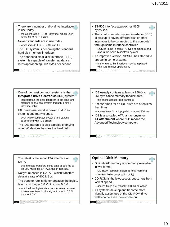
RLL Storage
• The term run-length limited (RLL) means the
run of zeros (zeros in a row) is limited.
– a common RLL encoding scheme is RLL 2,7,
which means the run of zeros is always between
two and seven
• An RLL drive often contains 27 tracks instead
of the 18 found on the MFM drive.
• Fig 13–24 is a comparison of MFM & RLL.
– besides holding more information, the RLL drive
can be written and read at a higher rate
107
Copyright ©2009 by Pearson Education, Inc.
Upper Saddle River, New Jersey 07458 • All rights reserved.
The Intel Microprocessors: 8086/8088, 80186/80188, 80286, 80386, 80486 Pentium,
Pentium Pro Processor, Pentium II, Pentium, 4, and Core2 with 64-bit Extensions
Architecture, Programming, and Interfacing, Eighth Edition
Barry B. Brey
Figure 13–24 A comparison of MFM with RLL using data 101001011.
108
7/15/2011
19
Copyright ©2009 by Pearson Education, Inc.
Upper Saddle River, New Jersey 07458 • All rights reserved.
The Intel Microprocessors: 8086/8088, 80186/80188, 80286, 80386, 80486 Pentium,
Pentium Pro Processor, Pentium II, Pentium, 4, and Core2 with 64-bit Extensions
Architecture, Programming, and Interfacing, Eighth Edition
Barry B. Brey
• There are a number of disk drive interfaces
in use today.
– the oldest is the ST-506 interface, which uses
either MFM or RLL data
• Newer standards are in use today.
– which include ESDI, SCSI, and IDE
• The IDE system is becoming the standard
hard disk memory interface.
• The enhanced small disk interface (ESDI)
system is capable of transferring data at
rates approaching 10M bytes per second.
109
Copyright ©2009 by Pearson Education, Inc.
Upper Saddle River, New Jersey 07458 • All rights reserved.
The Intel Microprocessors: 8086/8088, 80186/80188, 80286, 80386, 80486 Pentium,
Pentium Pro Processor, Pentium II, Pentium, 4, and Core2 with 64-bit Extensions
Architecture, Programming, and Interfacing, Eighth Edition
Barry B. Brey
• ST-506 interface approaches 860K
bytes/sec.
• The small computer system interface (SCSI)
allows up to seven different disk or other
interfaces to be connected to the computer
through same interface controller.
– SCSI is found in some PC-type computers and
also in the Apple Macintosh system
• An improved version, SCSI-II, has started to
appear in some systems.
– in the future, this interface may be replaced
with IDE in most applications
110
Copyright ©2009 by Pearson Education, Inc.
Upper Saddle River, New Jersey 07458 • All rights reserved.
The Intel Microprocessors: 8086/8088, 80186/80188, 80286, 80386, 80486 Pentium,
Pentium Pro Processor, Pentium II, Pentium, 4, and Core2 with 64-bit Extensions
Architecture, Programming, and Interfacing, Eighth Edition
Barry B. Brey
• One of the most common systems is the
integrated drive electronics (IDE) system.
– incorporates the disk controller in the drive and
attaches to the host system through a small
interface cable
• IDE drives are found in newer IBM PS-2
systems and many clones.
– even Apple computer systems are starting
to be found with IDE drives
• The IDE interface is also capable of driving
other I/O devices besides the hard disk.
111
Copyright ©2009 by Pearson Education, Inc.
Upper Saddle River, New Jersey 07458 • All rights reserved.
The Intel Microprocessors: 8086/8088, 80186/80188, 80286, 80386, 80486 Pentium,
Pentium Pro Processor, Pentium II, Pentium, 4, and Core2 with 64-bit Extensions
Architecture, Programming, and Interfacing, Eighth Edition
Barry B. Brey
• IDE usually contains at least a 256K- to
8M-byte cache memory for disk data.
– the cache speeds disk transfers
• Access times for an IDE drive are often less
than 8 ms.
– access time for a floppy-disk is about 200 ms
• IDE is also called ATA, an acronym for
AT attachment where “AT” means the
Advanced Technology computer.
112
Copyright ©2009 by Pearson Education, Inc.
Upper Saddle River, New Jersey 07458 • All rights reserved.
The Intel Microprocessors: 8086/8088, 80186/80188, 80286, 80386, 80486 Pentium,
Pentium Pro Processor, Pentium II, Pentium, 4, and Core2 with 64-bit Extensions
Architecture, Programming, and Interfacing, Eighth Edition
Barry B. Brey
• The latest is the serial ATA interface or
SATA.
– this interface transfers serial data at 150 MBps
(or 300 MBps for SATA2), faster than IDE
• Not yet released is SATA3, which transfers
data at a rate of 600 MBps.
• The transfer rate is higher because the logic 1
level is no longer 5.0 V. It is now 0.5 V.
– which allows higher data transfer rates because
it takes less time for the signal to rise to 0.5 V
than to 5.0 V
113
Copyright ©2009 by Pearson Education, Inc.
Upper Saddle River, New Jersey 07458 • All rights reserved.
The Intel Microprocessors: 8086/8088, 80186/80188, 80286, 80386, 80486 Pentium,
Pentium Pro Processor, Pentium II, Pentium, 4, and Core2 with 64-bit Extensions
Architecture, Programming, and Interfacing, Eighth Edition
Barry B. Brey
Optical Disk Memory
• Optical disk memory is commonly available
in two forms:
– CD-ROM (compact disk/read only memory)
– WORM (write once/read mostly)
• CD-ROM is the lowest cost, but suffers from
lack of speed.
– access times are typically 300 ms or longer
• As systems develop and become more
visually active, use of the CD-ROM drive
will become even more common.
114
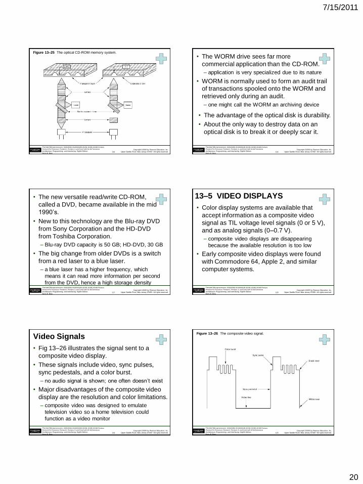
7/15/2011
20
Copyright ©2009 by Pearson Education, Inc.
Upper Saddle River, New Jersey 07458 • All rights reserved.
The Intel Microprocessors: 8086/8088, 80186/80188, 80286, 80386, 80486 Pentium,
Pentium Pro Processor, Pentium II, Pentium, 4, and Core2 with 64-bit Extensions
Architecture, Programming, and Interfacing, Eighth Edition
Barry B. Brey
Figure 13–25 The optical CD-ROM memory system.
115
Copyright ©2009 by Pearson Education, Inc.
Upper Saddle River, New Jersey 07458 • All rights reserved.
The Intel Microprocessors: 8086/8088, 80186/80188, 80286, 80386, 80486 Pentium,
Pentium Pro Processor, Pentium II, Pentium, 4, and Core2 with 64-bit Extensions
Architecture, Programming, and Interfacing, Eighth Edition
Barry B. Brey
• The WORM drive sees far more
commercial application than the CD-ROM.
– application is very specialized due to its nature
• WORM is normally used to form an audit trail
of transactions spooled onto the WORM and
retrieved only during an audit.
– one might call the WORM an archiving device
• The advantage of the optical disk is durability.
• About the only way to destroy data on an
optical disk is to break it or deeply scar it.
116
Copyright ©2009 by Pearson Education, Inc.
Upper Saddle River, New Jersey 07458 • All rights reserved.
The Intel Microprocessors: 8086/8088, 80186/80188, 80286, 80386, 80486 Pentium,
Pentium Pro Processor, Pentium II, Pentium, 4, and Core2 with 64-bit Extensions
Architecture, Programming, and Interfacing, Eighth Edition
Barry B. Brey
• The new versatile read/write CD-ROM,
called a DVD, became available in the mid
1990’s.
• New to this technology are the Blu-ray DVD
from Sony Corporation and the HD-DVD
from Toshiba Corporation.
– Blu-ray DVD capacity is 50 GB; HD-DVD, 30 GB
• The big change from older DVDs is a switch
from a red laser to a blue laser.
– a blue laser has a higher frequency, which
means it can read more information per second
from the DVD, hence a high storage density
117
Copyright ©2009 by Pearson Education, Inc.
Upper Saddle River, New Jersey 07458 • All rights reserved.
The Intel Microprocessors: 8086/8088, 80186/80188, 80286, 80386, 80486 Pentium,
Pentium Pro Processor, Pentium II, Pentium, 4, and Core2 with 64-bit Extensions
Architecture, Programming, and Interfacing, Eighth Edition
Barry B. Brey
13–5 VIDEO DISPLAYS
• Color display systems are available that
accept information as a composite video
signal as TIL voltage level signals (0 or 5 V),
and as analog signals (0–0.7 V).
– composite video displays are disappearing
because the available resolution is too low
• Early composite video displays were found
with Commodore 64, Apple 2, and similar
computer systems.
118
Copyright ©2009 by Pearson Education, Inc.
Upper Saddle River, New Jersey 07458 • All rights reserved.
The Intel Microprocessors: 8086/8088, 80186/80188, 80286, 80386, 80486 Pentium,
Pentium Pro Processor, Pentium II, Pentium, 4, and Core2 with 64-bit Extensions
Architecture, Programming, and Interfacing, Eighth Edition
Barry B. Brey
Video Signals
• Fig 13–26 illustrates the signal sent to a
composite video display.
• These signals include video, sync pulses,
sync pedestals, and a color burst.
– no audio signal is shown; one often doesn’t exist
• Major disadvantages of the composite video
display are the resolution and color limitations.
– composite video was designed to emulate
television video so a home television could
function as a video monitor
119
Copyright ©2009 by Pearson Education, Inc.
Upper Saddle River, New Jersey 07458 • All rights reserved.
The Intel Microprocessors: 8086/8088, 80186/80188, 80286, 80386, 80486 Pentium,
Pentium Pro Processor, Pentium II, Pentium, 4, and Core2 with 64-bit Extensions
Architecture, Programming, and Interfacing, Eighth Edition
Barry B. Brey
Figure 13–26 The composite video signal.
120
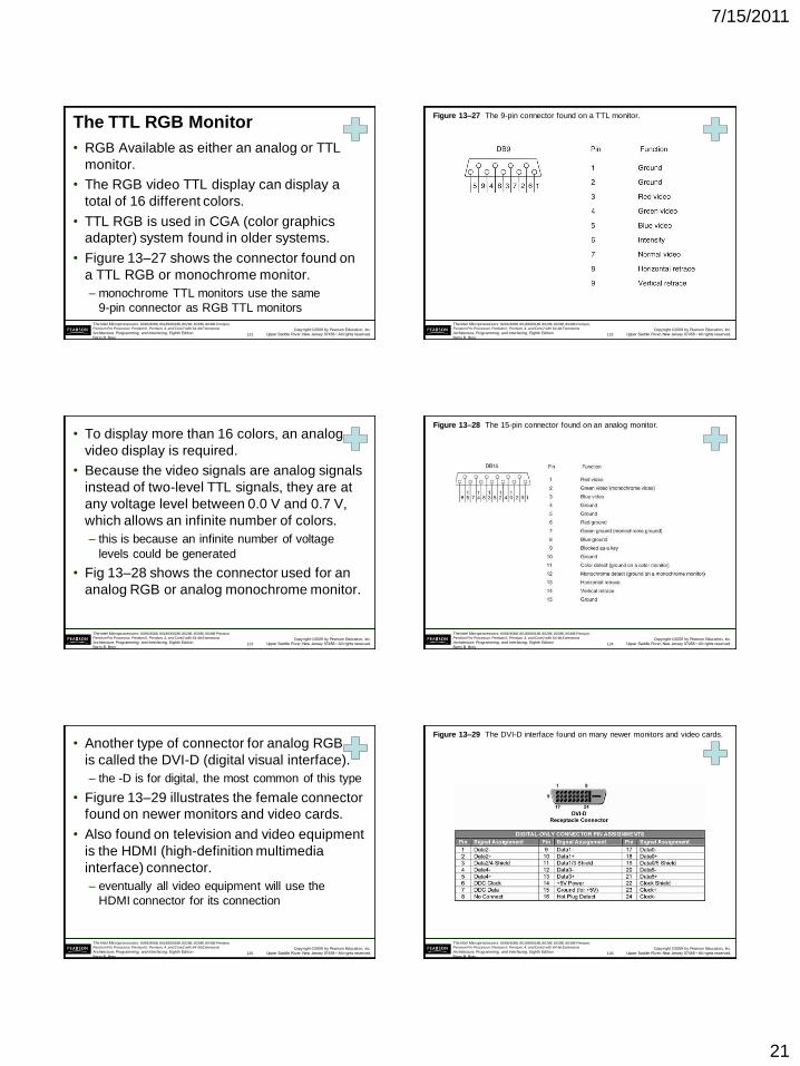
7/15/2011
21
Copyright ©2009 by Pearson Education, Inc.
Upper Saddle River, New Jersey 07458 • All rights reserved.
The Intel Microprocessors: 8086/8088, 80186/80188, 80286, 80386, 80486 Pentium,
Pentium Pro Processor, Pentium II, Pentium, 4, and Core2 with 64-bit Extensions
Architecture, Programming, and Interfacing, Eighth Edition
Barry B. Brey
The TTL RGB Monitor
• RGB Available as either an analog or TTL
monitor.
• The RGB video TTL display can display a
total of 16 different colors.
• TTL RGB is used in CGA (color graphics
adapter) system found in older systems.
• Figure 13–27 shows the connector found on
a TTL RGB or monochrome monitor.
– monochrome TTL monitors use the same
9-pin connector as RGB TTL monitors
121
Copyright ©2009 by Pearson Education, Inc.
Upper Saddle River, New Jersey 07458 • All rights reserved.
The Intel Microprocessors: 8086/8088, 80186/80188, 80286, 80386, 80486 Pentium,
Pentium Pro Processor, Pentium II, Pentium, 4, and Core2 with 64-bit Extensions
Architecture, Programming, and Interfacing, Eighth Edition
Barry B. Brey
Figure 13–27 The 9-pin connector found on a TTL monitor.
122
Copyright ©2009 by Pearson Education, Inc.
Upper Saddle River, New Jersey 07458 • All rights reserved.
The Intel Microprocessors: 8086/8088, 80186/80188, 80286, 80386, 80486 Pentium,
Pentium Pro Processor, Pentium II, Pentium, 4, and Core2 with 64-bit Extensions
Architecture, Programming, and Interfacing, Eighth Edition
Barry B. Brey
• To display more than 16 colors, an analog
video display is required.
• Because the video signals are analog signals
instead of two-level TTL signals, they are at
any voltage level between 0.0 V and 0.7 V,
which allows an infinite number of colors.
– this is because an infinite number of voltage
levels could be generated
• Fig 13–28 shows the connector used for an
analog RGB or analog monochrome monitor.
123
Copyright ©2009 by Pearson Education, Inc.
Upper Saddle River, New Jersey 07458 • All rights reserved.
The Intel Microprocessors: 8086/8088, 80186/80188, 80286, 80386, 80486 Pentium,
Pentium Pro Processor, Pentium II, Pentium, 4, and Core2 with 64-bit Extensions
Architecture, Programming, and Interfacing, Eighth Edition
Barry B. Brey
Figure 13–28 The 15-pin connector found on an analog monitor.
124
Copyright ©2009 by Pearson Education, Inc.
Upper Saddle River, New Jersey 07458 • All rights reserved.
The Intel Microprocessors: 8086/8088, 80186/80188, 80286, 80386, 80486 Pentium,
Pentium Pro Processor, Pentium II, Pentium, 4, and Core2 with 64-bit Extensions
Architecture, Programming, and Interfacing, Eighth Edition
Barry B. Brey
• Another type of connector for analog RGB
is called the DVI-D (digital visual interface).
– the -D is for digital, the most common of this type
• Figure 13–29 illustrates the female connector
found on newer monitors and video cards.
• Also found on television and video equipment
is the HDMI (high-definition multimedia
interface) connector.
– eventually all video equipment will use the
HDMI connector for its connection
125
Copyright ©2009 by Pearson Education, Inc.
Upper Saddle River, New Jersey 07458 • All rights reserved.
The Intel Microprocessors: 8086/8088, 80186/80188, 80286, 80386, 80486 Pentium,
Pentium Pro Processor, Pentium II, Pentium, 4, and Core2 with 64-bit Extensions
Architecture, Programming, and Interfacing, Eighth Edition
Barry B. Brey
Figure 13–29 The DVI-D interface found on many newer monitors and video cards.
126
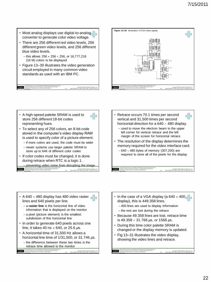
7/15/2011
22
Copyright ©2009 by Pearson Education, Inc.
Upper Saddle River, New Jersey 07458 • All rights reserved.
The Intel Microprocessors: 8086/8088, 80186/80188, 80286, 80386, 80486 Pentium,
Pentium Pro Processor, Pentium II, Pentium, 4, and Core2 with 64-bit Extensions
Architecture, Programming, and Interfacing, Eighth Edition
Barry B. Brey
• Most analog displays use digital-to-analog
converter to generate color video voltage.
• There are 256 different red video levels, 256
different green video levels, and 256 different
blue video levels.
– this allows 256 256 256, or 16,777,216
(16 M) colors to be displayed
• Figure 13–30 illustrates the video generation
circuit employed in many common video
standards as used with an IBM PC.
127
Copyright ©2009 by Pearson Education, Inc.
Upper Saddle River, New Jersey 07458 • All rights reserved.
The Intel Microprocessors: 8086/8088, 80186/80188, 80286, 80386, 80486 Pentium,
Pentium Pro Processor, Pentium II, Pentium, 4, and Core2 with 64-bit Extensions
Architecture, Programming, and Interfacing, Eighth Edition
Barry B. Brey
Figure 13–30 Generation of VGA video signals.
128
Copyright ©2009 by Pearson Education, Inc.
Upper Saddle River, New Jersey 07458 • All rights reserved.
The Intel Microprocessors: 8086/8088, 80186/80188, 80286, 80386, 80486 Pentium,
Pentium Pro Processor, Pentium II, Pentium, 4, and Core2 with 64-bit Extensions
Architecture, Programming, and Interfacing, Eighth Edition
Barry B. Brey
• A high-speed palette SRAM is used to
store 256 different 18-bit codes
representing hues.
• To select any of 256 colors, an 8-bit code
stored in the computer’s video display RAM
is used to specify color of a picture element.
– if more colors are used, the code must be wider
– newer systems use larger palette SRAM to
store up to 64K of different color codes
• If color codes must be changed, it is done
during retrace when RTC is a logic 1.
– preventing video noise from disrupting the image
129
Copyright ©2009 by Pearson Education, Inc.
Upper Saddle River, New Jersey 07458 • All rights reserved.
The Intel Microprocessors: 8086/8088, 80186/80188, 80286, 80386, 80486 Pentium,
Pentium Pro Processor, Pentium II, Pentium, 4, and Core2 with 64-bit Extensions
Architecture, Programming, and Interfacing, Eighth Edition
Barry B. Brey
• Retrace occurs 70.1 times per second
vertical and 31,500 times per second
horizontal direction for a 640 480 display.
– used to move the electron beam to the upper
left corner for vertical retrace and the left
margin of the screen for horizontal retrace
• The resolution of the display determines the
memory required for the video interface card.
– 640 480 bytes of memory (307,200) are
required to store all of the pixels for the display
130
Copyright ©2009 by Pearson Education, Inc.
Upper Saddle River, New Jersey 07458 • All rights reserved.
The Intel Microprocessors: 8086/8088, 80186/80188, 80286, 80386, 80486 Pentium,
Pentium Pro Processor, Pentium II, Pentium, 4, and Core2 with 64-bit Extensions
Architecture, Programming, and Interfacing, Eighth Edition
Barry B. Brey
• A 640 480 display has 480 video raster
lines and 640 pixels per line.
– a raster line is the horizontal line of video
information that is displayed on the monitor
– a pixel (picture element) is the smallest
subdivision of this horizontal line
• In order to generate 640 pixels across one
line, it takes 40 ns 640, or 25.6 µs.
• A horizontal time of 31,500 Hz allows a
horizontal line time of 1/31,500, or 31.746 µs.
– the difference between these two times is the
retrace time allowed to the monitor
131
Copyright ©2009 by Pearson Education, Inc.
Upper Saddle River, New Jersey 07458 • All rights reserved.
The Intel Microprocessors: 8086/8088, 80186/80188, 80286, 80386, 80486 Pentium,
Pentium Pro Processor, Pentium II, Pentium, 4, and Core2 with 64-bit Extensions
Architecture, Programming, and Interfacing, Eighth Edition
Barry B. Brey
• In the case of a VGA display (a 640 400
display), this is 449.358 lines.
– 400 lines are used to display information
– the rest are lost during the retrace
• Because 49.358 lines are lost, retrace time
is 49.358 31.766 µs, or 1568 µs.
• During this time color palette SRAM is
changed or the display memory is updated.
• Fig 13–31 illustrates the video display,
showing the video lines and retrace.
132
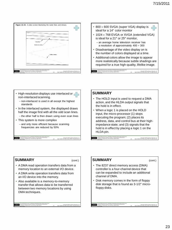
7/15/2011
23
Copyright ©2009 by Pearson Education, Inc.
Upper Saddle River, New Jersey 07458 • All rights reserved.
The Intel Microprocessors: 8086/8088, 80186/80188, 80286, 80386, 80486 Pentium,
Pentium Pro Processor, Pentium II, Pentium, 4, and Core2 with 64-bit Extensions
Architecture, Programming, and Interfacing, Eighth Edition
Barry B. Brey
Figure 13–31 A video screen illustrating the raster lines and retrace.
133
Copyright ©2009 by Pearson Education, Inc.
Upper Saddle River, New Jersey 07458 • All rights reserved.
The Intel Microprocessors: 8086/8088, 80186/80188, 80286, 80386, 80486 Pentium,
Pentium Pro Processor, Pentium II, Pentium, 4, and Core2 with 64-bit Extensions
Architecture, Programming, and Interfacing, Eighth Edition
Barry B. Brey
• 800 600 SVGA (super VGA) display is
ideal for a 14 color monitor
• 1024 768 EVGA or XVGA (extended VGA)
is ideal for a 21 or 25 monitor,
– an average home television receiver has
a resolution of approximately 400 300
• Disadvantage of the video display on is
the number of colors displayed at a time.
• Additional colors allow the image to appear
more realistically because subtle shadings are
required for a true high-quality, lifelike image.
134
Copyright ©2009 by Pearson Education, Inc.
Upper Saddle River, New Jersey 07458 • All rights reserved.
The Intel Microprocessors: 8086/8088, 80186/80188, 80286, 80386, 80486 Pentium,
Pentium Pro Processor, Pentium II, Pentium, 4, and Core2 with 64-bit Extensions
Architecture, Programming, and Interfacing, Eighth Edition
Barry B. Brey
• High-resolution displays use interlaced or
non-interlaced scanning.
– non-interlaced is used in all except the highest
standards
• In the interlaced system, the displayed draws
half the image first with all the odd scan lines.
– the other half is then drawn using even scan lines
• This system is more complex
– and only more efficient because scanning
frequencies are reduced by 50%
135
Copyright ©2009 by Pearson Education, Inc.
Upper Saddle River, New Jersey 07458 • All rights reserved.
The Intel Microprocessors: 8086/8088, 80186/80188, 80286, 80386, 80486 Pentium,
Pentium Pro Processor, Pentium II, Pentium, 4, and Core2 with 64-bit Extensions
Architecture, Programming, and Interfacing, Eighth Edition
Barry B. Brey
SUMMARY
• The HOLD input is used to request a DMA
action, and the HLDA output signals that
the hold is in effect.
• When a logic 1 is placed on the HOLD
input, the micro-processor (1) stops
executing the program; (2) places its
address, data, and control bus at their high-
impedance state; and (3) signals that the
hold is in effect by placing a logic 1 on the
HLDA pin.
136
Copyright ©2009 by Pearson Education, Inc.
Upper Saddle River, New Jersey 07458 • All rights reserved.
The Intel Microprocessors: 8086/8088, 80186/80188, 80286, 80386, 80486 Pentium,
Pentium Pro Processor, Pentium II, Pentium, 4, and Core2 with 64-bit Extensions
Architecture, Programming, and Interfacing, Eighth Edition
Barry B. Brey
SUMMARY
• A DMA read operation transfers data from a
memory location to an external I/O device.
• A DMA write operation transfers data from
an I/O device into the memory.
• Also available is a memory-to-memory
transfer that allows data to be transferred
between two memory locations by using
DMA techniques.
(cont.)
137
Copyright ©2009 by Pearson Education, Inc.
Upper Saddle River, New Jersey 07458 • All rights reserved.
The Intel Microprocessors: 8086/8088, 80186/80188, 80286, 80386, 80486 Pentium,
Pentium Pro Processor, Pentium II, Pentium, 4, and Core2 with 64-bit Extensions
Architecture, Programming, and Interfacing, Eighth Edition
Barry B. Brey
SUMMARY
• The 8237 direct memory access (DMA)
controller is a four-channel device that
can be expanded to include an additional
channel of DMA.
• Disk memory comes in the form of floppy
disk storage that is found as 3-1/2" micro-
floppy disks.
(cont.)
138
7/15/2011
24
Copyright ©2009 by Pearson Education, Inc.
Upper Saddle River, New Jersey 07458 • All rights reserved.
The Intel Microprocessors: 8086/8088, 80186/80188, 80286, 80386, 80486 Pentium,
Pentium Pro Processor, Pentium II, Pentium, 4, and Core2 with 64-bit Extensions
Architecture, Programming, and Interfacing, Eighth Edition
Barry B. Brey
SUMMARY
• Floppy disk memory data are stored using
NRZ (non-return to zero) recording.
• This method saturates the disk with one
polarity of magnetic energy for a logic 1
and the opposite polarity for a logic 0.
• In either case, the magnetic field never
returns to 0.
• This technique eliminates the need for a
separate erase head.
(cont.)
139
Copyright ©2009 by Pearson Education, Inc.
Upper Saddle River, New Jersey 07458 • All rights reserved.
The Intel Microprocessors: 8086/8088, 80186/80188, 80286, 80386, 80486 Pentium,
Pentium Pro Processor, Pentium II, Pentium, 4, and Core2 with 64-bit Extensions
Architecture, Programming, and Interfacing, Eighth Edition
Barry B. Brey
SUMMARY
• The MFM scheme records a data pulse for
a logic 1, no data or clock for the first logic
0 of a string of zeros, and a clock pulse for
the second and subsequent logic 0 in a
string of zeros.
• The RLL scheme encodes data so that 50%
more information can be packed onto the
same disk area. Most modern disk memory
systems use the RLL encoding scheme.
(cont.)
140
Copyright ©2009 by Pearson Education, Inc.
Upper Saddle River, New Jersey 07458 • All rights reserved.
The Intel Microprocessors: 8086/8088, 80186/80188, 80286, 80386, 80486 Pentium,
Pentium Pro Processor, Pentium II, Pentium, 4, and Core2 with 64-bit Extensions
Architecture, Programming, and Interfacing, Eighth Edition
Barry B. Brey
SUMMARY
• Video monitors are either TTL or analog.
• The TTL monitor uses two discrete voltage
levels of 0 V and 5.0 V.
• The analog monitor uses an infinite number
of voltage levels between 0.0 V and 0.7 V.
• The analog monitor can display an infinite
number of video levels, while the TTL
monitor is limited to two video levels.
(cont.)
141
Copyright ©2009 by Pearson Education, Inc.
Upper Saddle River, New Jersey 07458 • All rights reserved.
The Intel Microprocessors: 8086/8088, 80186/80188, 80286, 80386, 80486 Pentium,
Pentium Pro Processor, Pentium II, Pentium, 4, and Core2 with 64-bit Extensions
Architecture, Programming, and Interfacing, Eighth Edition
Barry B. Brey
SUMMARY
• The color TTL monitor displays 16 different
colors.
• This is accomplished through three video
signals (red, green, and blue) and an
intensity input.
• The analog color monitor can display an
infinite number of colors through its three
video inputs.
(cont.)
142
Copyright ©2009 by Pearson Education, Inc.
Upper Saddle River, New Jersey 07458 • All rights reserved.
The Intel Microprocessors: 8086/8088, 80186/80188, 80286, 80386, 80486 Pentium,
Pentium Pro Processor, Pentium II, Pentium, 4, and Core2 with 64-bit Extensions
Architecture, Programming, and Interfacing, Eighth Edition
Barry B. Brey
SUMMARY
• In practice, the most common form of color
analog display system (VGA) can display
16 M different colors.
• The video standards found today include
VGA (640 ´ 480), SVGA (800 ´ 600), and
EVGA or XVGA (1024 ´ 768).
• In all three cases, the video information
can be 16M colors.
143