Embed Size (px)
Citation preview
1
CHAP 4 FINITE ELEMENT ANALYSIS OF BEAMS AND FRAMES
2
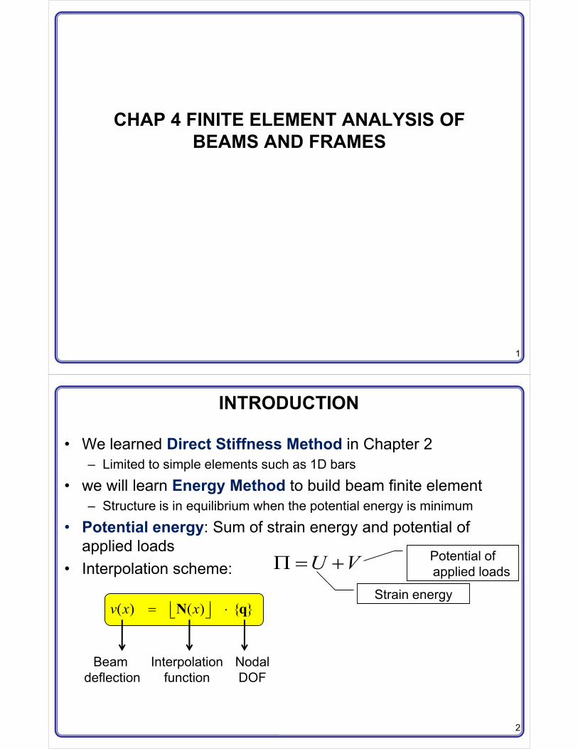
INTRODUCTION
• We learned Direct Stiffness Method in Chapter 2– Limited to simple elements such as 1D bars
• we will learn Energy Method to build beam finite element– Structure is in equilibrium when the potential energy is minimum
• Potential energy: Sum of strain energy and potential of applied loads
• Interpolation scheme:
( ) ( ) { }v x x� �� �� �N q
Beam deflection
Interpolationfunction
NodalDOF
Potential of applied loads
Strain energy
U V� �
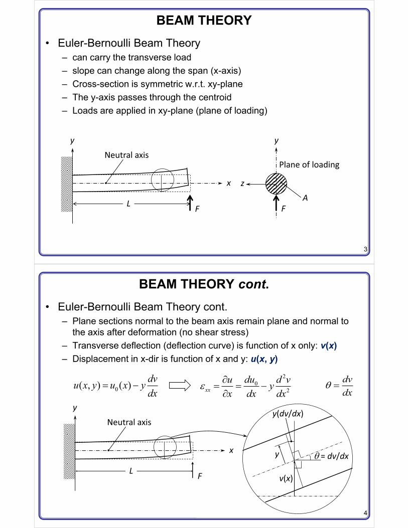
3
BEAM THEORY• Euler-Bernoulli Beam Theory
– can carry the transverse load– slope can change along the span (x-axis)– Cross-section is symmetric w.r.t. xy-plane– The y-axis passes through the centroid– Loads are applied in xy-plane (plane of loading)
LF
x
y
F
Plane of loading
y
z
Neutral axis
A
4
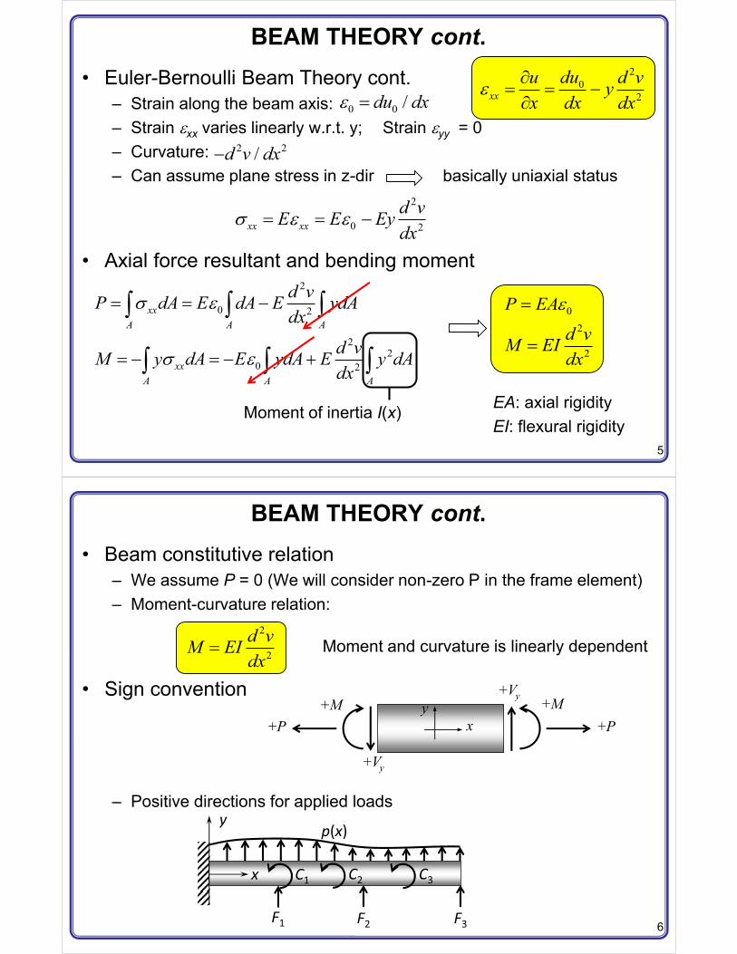
BEAM THEORY cont.• Euler-Bernoulli Beam Theory cont.
– Plane sections normal to the beam axis remain plane and normal to the axis after deformation (no shear stress)
– Transverse deflection (deflection curve) is function of x only: v(x)– Displacement in x-dir is function of x and y: u(x, y)
y
y(dv/dx)
�= dv/dx
v(x)L
F
x
y
Neutral axis
0( , ) ( ) dvu x y u x ydx
� �2
02xx
duu d vyx dx dx
�� � ��
dvdx
�
5
BEAM THEORY cont.• Euler-Bernoulli Beam Theory cont.
– Strain along the beam axis:– Strain xx varies linearly w.r.t. y; Strain yy = 0– Curvature:– Can assume plane stress in z-dir basically uniaxial status
• Axial force resultant and bending moment
20
2xxduu d vy
x dx dx �
� � ��0 0 /du dx �
2 2/d v dx�
2
0 2xx xxd vE E Eydx
� � � �
2
0 2
22
0 2
xxA A A
xxA A A
d vP dA E dA E ydAdx
d vM y dA E ydA E y dAdx
�
�
� � �
� � � �
� � �
� � �
Moment of inertia I(x)
02
2
P EAd vM EIdx
�
�
EA: axial rigidityEI: flexural rigidity
6
BEAM THEORY cont.• Beam constitutive relation
– We assume P = 0 (We will consider non-zero P in the frame element)– Moment-curvature relation:
• Sign convention
– Positive directions for applied loads
2
2d vM EIdx
� Moment and curvature is linearly dependent
+P +P+M+M
+Vy
+Vy
yx
p(x)
F1 F2 F3
C1 C2 C3
y
x
7
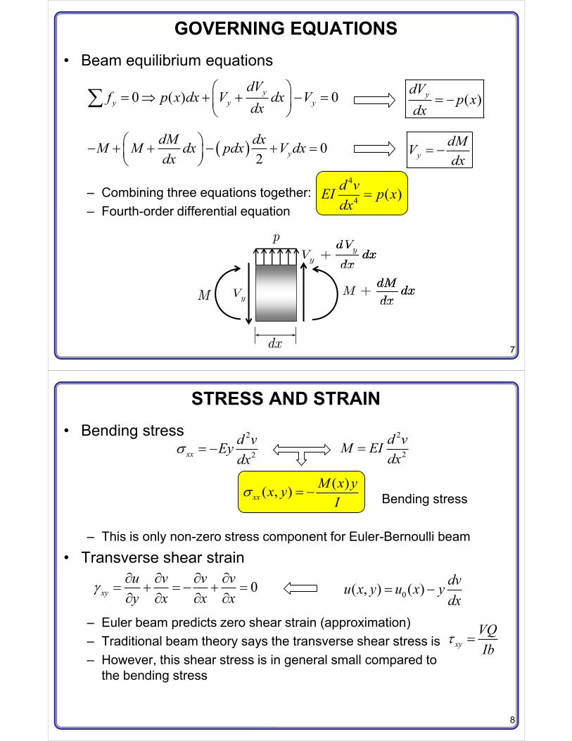
GOVERNING EQUATIONS• Beam equilibrium equations
– Combining three equations together:– Fourth-order differential equation
yy
dVV dx
dxyyy
dMM dx
dxyVM
dx
p
0 ( ) 0yy y y
dVf p x dx V dx V
dx� �
� � � �� �� �
� ( )ydVp x
dx� �
� � 02 y
dM dxM M dx pdx V dxdx
� �� � �� �� �
4
4 ( )d vEI p xdx
�
ydMVdx
� �
8
STRESS AND STRAIN• Bending stress
– This is only non-zero stress component for Euler-Bernoulli beam
• Transverse shear strain
– Euler beam predicts zero shear strain (approximation)– Traditional beam theory says the transverse shear stress is– However, this shear stress is in general small compared to
the bending stress
2
2xxd vEydx
� � �2
2d vM EIdx
�
( )( , )xxM x yx yI
� � �
0xyu v v vy x x x
� � � � �� � � �� � � � 0( , ) ( ) dvu x y u x y
dx� �
Bending stress
xyVQIb
� �
9
POTENTIAL ENERGY• Potential energy• Strain energy
– Strain energy density
– Strain energy per unit length
– Strain energy
U V� �
2 22 22 2
0 2 21 1 1 1( )2 2 2 2xx xx xx
d v d vU E E y Eydx dx
� � � � �
� � � � �� � � �� � � �
2 22 22 2
0 2 21 1( ) ( , , )2 2L
A A A
d v d vU x U x y z dA Ey dA E y dAdx dx
� � � �� � �� � � �
� � � �� � �
Moment of inertia
22
21( )2L
d vU x EIdx
� �� � �
� �
22
20 0
1( )2
L L
Ld vU U x dx EI dxdx
� �� � � �
� �� �
10
POTENTIAL ENERGY cont.• Potential energy of applied loads
• Potential energy
– Potential energy is a function of v(x) and slope– The beam is in equilibrium when � has its minimum value
01 1
( )( ) ( ) ( )CF NNL
ii i i
i i
dv xV p x v x dx Fv x Cdx� �
� � � �� ��
22
20 01 1
( )1 ( ) ( ) ( )2
CF NNL Li
i i ii i
dv xd vU V EI dx p x v x dx Fv x Cdx dx� �
� �� � � � � �� �
� �� �� �
�
vv*
0v
���
�
11
RAYLEIGH-RITZ METHOD1. Assume a deflection shape
– Unknown coefficients ci and known function fi(x)– Deflection curve v(x) must satisfy displacement boundary conditions
2. Obtain potential energy as function of coefficients
3. Apply the principle of minimum potential energy to determine the coefficients
1 1 2 2( ) ( ) ( )..... ( )n nv x c f x c f x c f x�
1 2( , ,... )nc c c U V� �
12
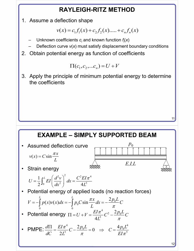
EXAMPLE – SIMPLY SUPPORTED BEAM• Assumed deflection curve
• Strain energy
• Potential energy of applied loads (no reaction forces)
• Potential energy
• PMPE:
p0
E,I,L( ) sin xv x C
L�
�
22 2 4
2 30
12 4
L d v C EIU EI dxdx L
�� �� �� �
� ��
00
0 0
2( ) ( ) sinL L p LxV p x v x dx p C dx C
L�
�� � � � � �� �
42 0
3
24
p LEIU V C CL�
�� � � �
440 0
3 5
2 402
p L p Ld EI C CdC L EI
�� �
�� � � � �
13
EXAMPLE – SIMPLY SUPPORTED BEAM cont.• Exact vs. approximate solutions
• Approximate bending moment and shear force
• Exact solutions
4 40 0
approx exact76.5 76.8p L p LC CEI EI
� �
22 20
2 2 3
3 30
3 3 2
4( ) sin sin
4( ) cos cosy
p Ld v x xM x EI EICdx L L L
p Ld v x xV x EI EICdx L L L
� � ��
� � ��
� � � � �
� � � � � �
33 40 0 0
20 0
00
1( )24 12 24
( )2 2
( )2y
p L p L pv x x x xEIp L pM x x x
p LV x p x
� �� � � �
� �
� �
� �
14
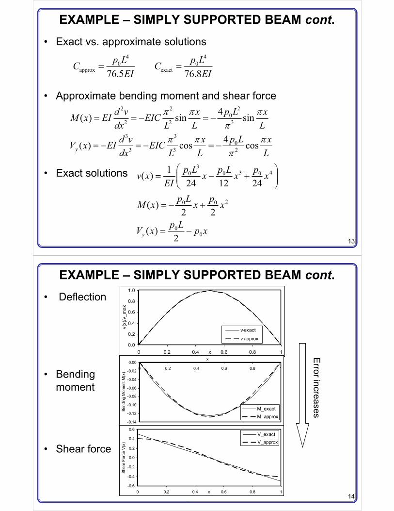
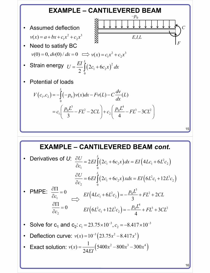
EXAMPLE – SIMPLY SUPPORTED BEAM cont.• Deflection
• Bendingmoment
• Shear force
0.0
0.2
0.4
0.6
0.8
1.0
0 0.2 0.4 0.6 0.8 1x
v(x)
/v_m
ax
v-exact
v-approx.
-0.14
-0.12
-0.10
-0.08
-0.06
-0.04
-0.02
0.000 0.2 0.4 0.6 0.8 1
x
Bend
ing
Mom
ent M
(x)
M_exactM_approx
-0.6
-0.4
-0.2
0.0
0.2
0.4
0.6
0 0.2 0.4 0.6 0.8 1x
Shea
r For
ce V
(x)
V_exactV_approx
Error increases
15
EXAMPLE – CANTILEVERED BEAM
• Assumed deflection
• Need to satisfy BC
• Strain energy
• Potential of loads
F
C
–p0
E,I,L2 31 2( )v x a bx c x c x�
(0) 0, (0) / 0v dv dx� � 2 31 2( )v x c x c x�
� �21 2
0
2 62
LEIU c c x dx� �
� � � �1 2 00
3 42 3 20 0
1 2
, ( ) ( ) ( )
2 33 4
L dvV c c p v x dx Fv L C Ldx
p L p Lc FL CL c FL CL
� � � � �
� � � �� � � � �� � � �
� � � �
�
16
EXAMPLE – CANTILEVERED BEAM cont.• Derivatives of U:
• PMPE:
• Solve for c1 and c2:
• Deflection curve:
• Exact solution:
� � � �
� � � �
21 2 1 2
1 0
2 31 2 1 2
2 0
2 2 6 4 6
6 2 6 6 12
L
L
U EI c c x dx EI Lc L cc
U EI c c x xdx EI L c L cc
�� �
�
�� �
�
�
�
1
2
0
0
c
c
���
���
��
� �
� �
32 20
1 2
42 3 3 20
1 2
4 6 23
6 12 34
p LEI Lc L c FL CL
p LEI L c L c FL CL
� �
� �
3 31 223.75 10 , 8.417 10c c� �� � � � �
� �3 2 3( ) 10 23.75 8.417v x x x�� �
� �2 3 41( ) 5400 800 30024
v x x x xEI
� � �
17
EXAMPLE – CANTILEVERED BEAM cont.• Deflection
• Bendingmoment
• Shear force
Error increases
0.0
0.0
0.0
0.0
0.0
0 0.2 0.4 0.6 0.8 1x
v(x)
/v_m
ax
v-exact
v-approx.
-100.00
0.00
100.00
200.00
300.00
400.00
500.00
0 0.2 0.4 0.6 0.8 1x
Bend
ing
Mom
ent M
(x) M_exact
M_approx
200.0
300.0
400.0
500.0
600.0
0 0.2 0.4 0.6 0.8 1x
Shea
r For
ce V
(x)
V_exactV_approx
18
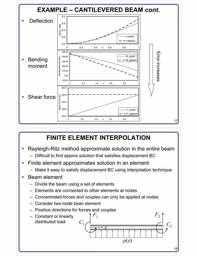
FINITE ELEMENT INTERPOLATION• Rayleigh-Ritz method approximate solution in the entire beam
– Difficult to find approx solution that satisfies displacement BC
• Finite element approximates solution in an element– Make it easy to satisfy displacement BC using interpolation technique
• Beam element– Divide the beam using a set of elements– Elements are connected to other elements at nodes– Concentrated forces and couples can only be applied at nodes– Consider two-node bean element– Positive directions for forces and couples– Constant or linearly
distributed loadF1 F2
C2C1
p(x)
x
19
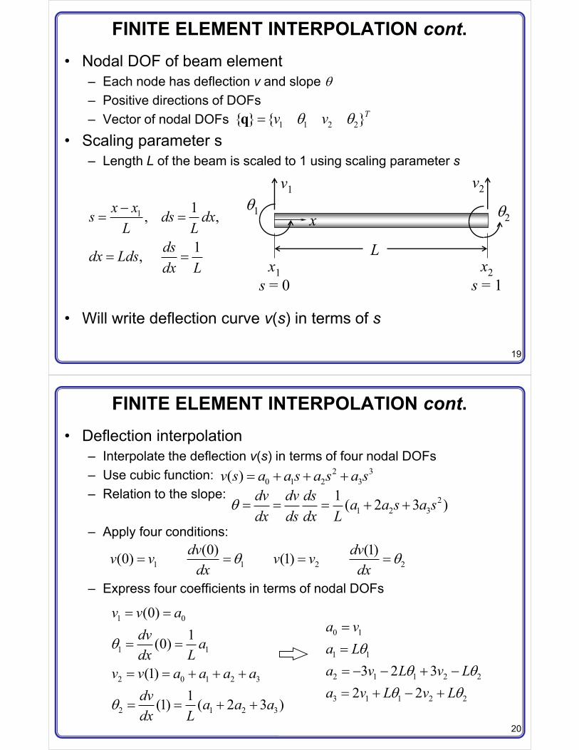
FINITE ELEMENT INTERPOLATION cont.• Nodal DOF of beam element
– Each node has deflection v and slope – Positive directions of DOFs– Vector of nodal DOFs
• Scaling parameter s– Length L of the beam is scaled to 1 using scaling parameter s
• Will write deflection curve v(s) in terms of s
v1 v2
21
Lx1s = 0
x2s = 1
x
1 1 2 2{ } { }Tv v �q
1 1, ,
1,
x xs ds dxL L
dsdx Ldsdx L
�� �
� �
20
FINITE ELEMENT INTERPOLATION cont.• Deflection interpolation
– Interpolate the deflection v(s) in terms of four nodal DOFs– Use cubic function:– Relation to the slope:
– Apply four conditions:
– Express four coefficients in terms of nodal DOFs
2 30 1 2 3( )v s a a s a s a s�
21 2 3
1 ( 2 3 )dv dv ds a a s a sdx ds dx L
� � �
1 1 2 2(0) (1)(0) (1)dv dvv v v vdx dx
� � � �
1 0
1 1
2 0 1 2 3
2 1 2 3
(0)1(0)
(1)1(1) ( 2 3 )
v v adv adx L
v v a a a adv a a adx L
� �
� �
� �
� �
0 1
1 1
2 1 1 2 2
3 1 1 2 2
3 2 32 2
a va La v L v La v L v L
��� � � �� �
21
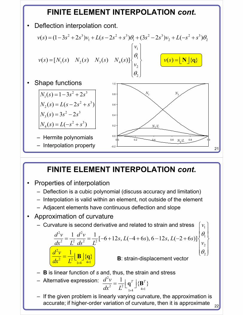
FINITE ELEMENT INTERPOLATION cont.• Deflection interpolation cont.
• Shape functions
– Hermite polynomials– Interpolation property
2 3 2 3 2 3 2 31 1 2 2( ) (1 3 2 ) ( 2 ) (3 2 ) ( )v s s s v L s s s s s v L s s � � � � �
2 31
2 32
2 33
2 34
( ) 1 3 2
( ) ( 2 )
( ) 3 2
( ) ( )
N s s sN s L s s sN s s s
N s L s s
� �
� �
� �
� �
1
11 2 3 4
2
2
( ) [ ( ) ( ) ( ) ( )]
v
v s N s N s N s N sv
� ! !! !� " #! !! !$ %
( ) { }v s � � �� �N q
-0.2
0.0
0.2
0.4
0.6
0.8
1.0
0.0 0.2 0.4 0.6 0.8 1.0
N1 N3
N2/L
N4/L
22
FINITE ELEMENT INTERPOLATION cont.• Properties of interpolation
– Deflection is a cubic polynomial (discuss accuracy and limitation)– Interpolation is valid within an element, not outside of the element– Adjacent elements have continuous deflection and slope
• Approximation of curvature– Curvature is second derivative and related to strain and stress
– B is linear function of s and, thus, the strain and stress– Alternative expression:
– If the given problem is linearly varying curvature, the approximation is accurate; if higher-order variation of curvature, then it is approximate
12 2
12 2 2 2
2
2
1 1 [ 6 12 , ( 4 6 ), 6 12 , ( 2 6 )]
vd v d v s L s s L s
vdx L ds L
� ! !! !� � � � � � " #! !! !$ %
2
2 24 11 4
1 { }d vdx L ��
� � �� �B q B: strain-displacement vector
2
2 24 11 4
1 { }T Td vdx L ��
� �� � � Bq
23
FINITE ELEMENT INTERPOLATION cont.• Approximation of bending moment and shear force
– Stress is proportional to M(s); M(s) is linear; stress is linear, too– Maximum stress always occurs at the node– Bending moment and shear force are not continuous between adjacent
elements
2
2 2( ) { }d v EIM s EIdx L
� � � �� �B q
3
3 3 [ 12 6 12 6 ]{ }ydM d v EIV EI L Ldx dx L
� � � � � � � � q
Linear
Constant
24
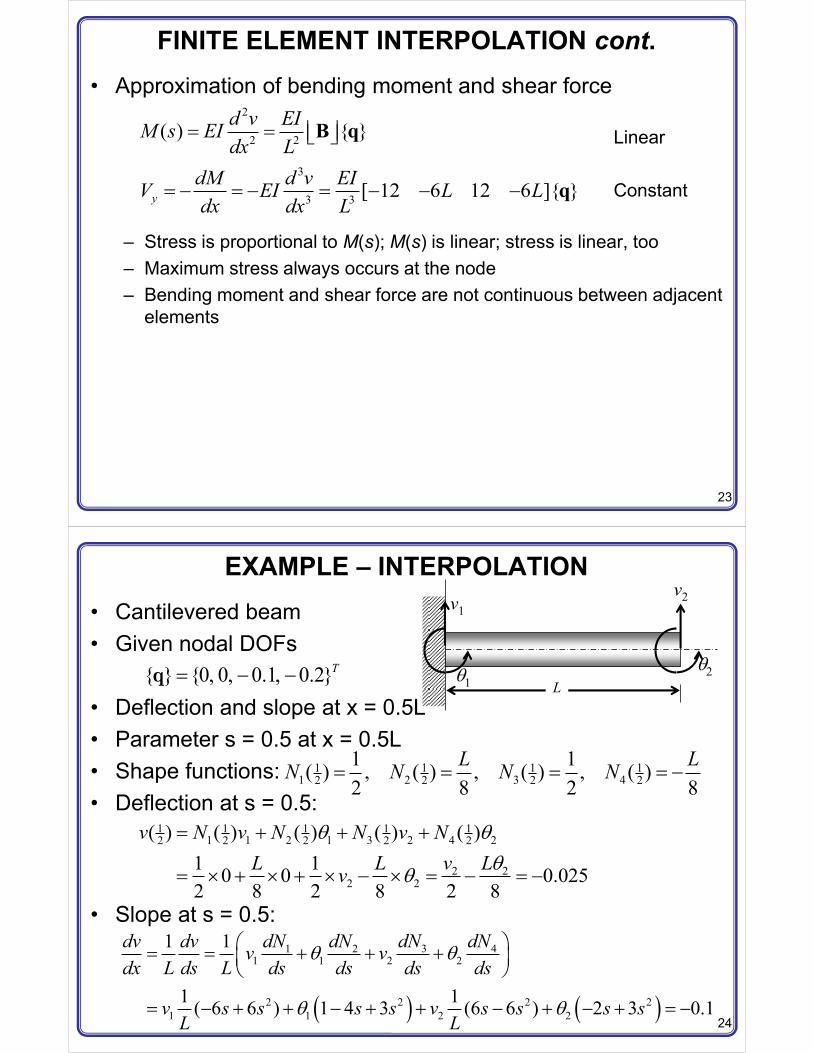
EXAMPLE – INTERPOLATION• Cantilevered beam• Given nodal DOFs
• Deflection and slope at x = 0.5L• Parameter s = 0.5 at x = 0.5L• Shape functions:• Deflection at s = 0.5:
• Slope at s = 0.5:
{ } {0, 0, 0.1, 0.2}T� � �qL
v1v2
21
1 1 1 11 2 3 42 2 2 2
1 1( ) , ( ) , ( ) , ( )2 8 2 8
L LN N N N� � � � �
1 1 1 1 11 1 2 1 3 2 4 22 2 2 2 2
2 22 2
( ) ( ) ( ) ( ) ( )1 10 0 0.0252 8 2 8 2 8
v N v N N v NL L v Lv
�
� � � � � � � � � �
� � � �
31 2 41 1 2 2
2 2 2 21 1 2 2
1 1
1 1( 6 6 ) 1 4 3 (6 6 ) 2 3 0.1
dNdv dv dN dN dNv vdx L ds L ds ds ds ds
v s s s s v s s s sL L
� �� � � �� �
� � � � � � �
25
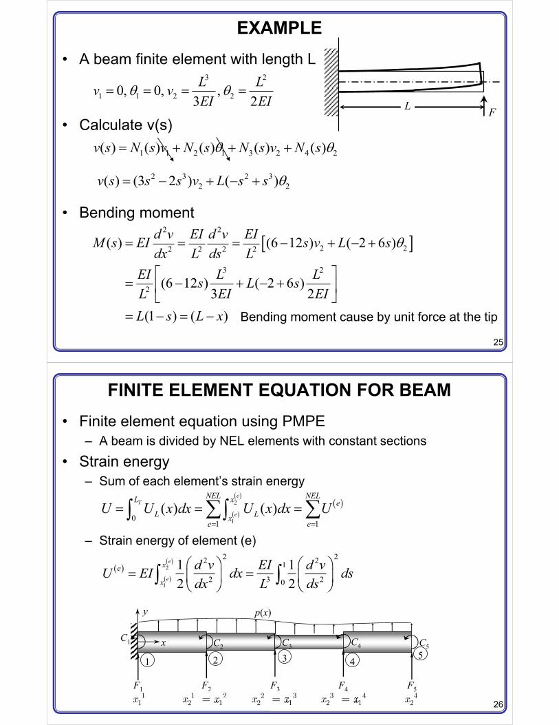
EXAMPLE• A beam finite element with length L
• Calculate v(s)
• Bending moment
3 2
1 1 2 20, 0, ,3 2L Lv vEI EI
� � � �
1 1 2 1 3 2 4 2( ) ( ) ( ) ( ) ( )v s N s v N s N s v N s �
2 3 2 32 2( ) (3 2 ) ( )v s s s v L s s � � �
& '2 2
2 22 2 2 2
3 2
2
( ) (6 12 ) ( 2 6 )
(6 12 ) ( 2 6 )3 2
(1 ) ( )
d v EI d v EIM s EI s v L sdx L ds L
EI L Ls L sL EI EIL s L x
� � � � �
( )� � � � �
� �� � � �
L F
Bending moment cause by unit force at the tip
26
FINITE ELEMENT EQUATION FOR BEAM• Finite element equation using PMPE
– A beam is divided by NEL elements with constant sections
• Strain energy– Sum of each element’s strain energy
– Strain energy of element (e)
p(x)
F1 F2 F3
C1 C2 C3
y
x
F4 F5
C4 C5
1 2 3 4 5
11x
1 22 1x x
221x
2 32 1x x
331x
3 42 1x x
441x
42x
� �
� �� �2
101 1
( ) ( )e
T
e
NEL NELL x eL Lx
e eU U x dx U x dx U
� �
� � �� �� �
� �� �
� �2
1
2 22 21
2 3 20
1 12 2
e
e
xe
x
d v EI d vU EI dx dsdx L ds
� � � �� �� � � �
� � � �� �
27
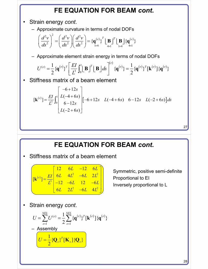
FE EQUATION FOR BEAM cont.• Strain energy cont.
– Approximate curvature in terms of nodal DOFs
– Approximate element strain energy in terms of nodal DOFs
• Stiffness matrix of a beam element
� � � �22 2 2
2 2 21 4 4 14 1 1 4
{ } { }T Te ed v d v d v
ds ds ds � �� �
� � � �� �� � � � � �� � � �� � � �� �
� � � �� �q B B q
� �� �
� � � � � � � �1( )3 0
1 1{ } { } { } [ ]{ }2 2
eTe e e e ee T TEIU ds
L( )� �� � � �� � � �� �� ��q B B q q k q
� � & '1
3 0
6 12( 4 6 )
[ ] 6 12 ( 4 6 ) 6 12 ( 2 6 )6 12( 2 6 )
e
sL sEI s L s s L s ds
sLL s
� ( )� �� � �� � � � �
�� �� �� � �
�k
28
FE EQUATION FOR BEAM cont.• Stiffness matrix of a beam element
• Strain energy cont.
– Assembly
� �2 2
3
2 2
12 6 12 66 4 6 2
[ ]12 6 12 6
6 2 6 4
e
L LL L L LEI
L LLL L L L
�( )� ��� ��� � �� �� ��� �
kSymmetric, positive semi-definiteProportional to EIInversely proportional to L
� � � � � �( )
1 1
1 { } [ ]{ }2
NEL NELe e ee T
e eU U
� �
� �� � q k q
1{ } [ ]{ }2
Ts s sU � Q K Q
29
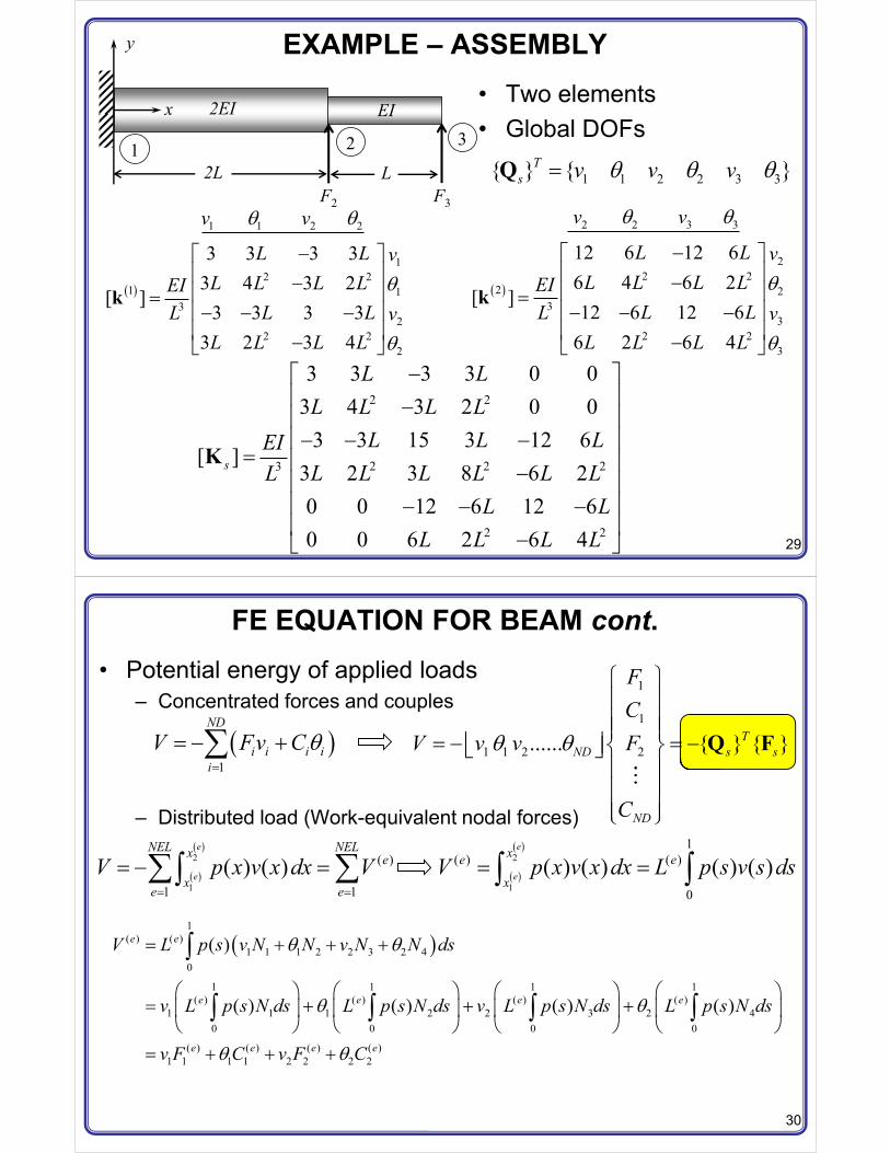
EXAMPLE – ASSEMBLY• Two elements• Global DOFs
F3F2
y
x
1 2 3
2EI EI
2L L 1 1 2 2 3 3{ } { }Ts v v v �Q
� �
1 1 2 2
12 2
1 13
22 2
2
3 3 3 33 4 3 2
[ ]3 3 3 3
3 2 3 4
v v
L L vL L L LEI
L LL vL L L L
�( )� ��� ��� � �� �� ��� �
k � �
2 2 3 3
22 2
2 23
32 2
3
12 6 12 66 4 6 2
[ ]12 6 12 6
6 2 6 4
v v
L L vL L L LEI
L LL vL L L L
�( )� ��� ��� � �� �� ��� �
k
2 2
2 2 23
2 2
3 3 3 3 0 03 4 3 2 0 0
3 3 15 3 12 6[ ]
3 2 3 8 6 20 0 12 6 12 60 0 6 2 6 4
s
L LL L L L
L L LEIL L L L L LL
L LL L L L
�( )� ��� �� � �� �
� � ��� �� �� � �� ��� �
K
30
FE EQUATION FOR BEAM cont.• Potential energy of applied loads
– Concentrated forces and couples
– Distributed load (Work-equivalent nodal forces)
� �1
ND
i i i ii
V Fv C�
� � �
1
1
1 1 2 2...... { } { }TND s s
ND
FC
V v v F
C
� ! !! !! !� � � �� � " #� �! !! !! !$ %
Q F
� �
� �2
1
( )
1 1( ) ( )
e
e
NEL NELx e
xe e
V p x v x dx V� �
� � �� �� � �
� �2
1
1( ) ( )
0
( ) ( ) ( ) ( )e
e
xe e
xV p x v x dx L p s v s ds� �� �
� �1
( ) ( )1 1 1 2 2 3 2 4
0
1 1 1 1( ) ( ) ( ) ( )
1 1 1 2 2 3 2 40 0 0 0
( ) ( ) ( ) ( )1 1 1 1 2 2 2 2
( )
( ) ( ) ( ) ( )
e e
e e e e
e e e e
V L p s v N N v N N ds
v L p s N ds L p s N ds v L p s N ds L p s N ds
v F C v F C
�
� � � � � � � �� � � � � � � � �
� � � � � � � ��
�
� � � �
31
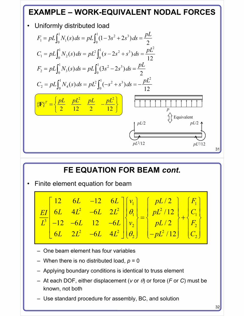
EXAMPLE – WORK-EQUIVALENT NODAL FORCES• Uniformly distributed load
pL/2 pL/2
pL2/12 pL2/12
p
Equivalent
1 1 2 31 10 0
( ) (1 3 2 )2pLF pL N s ds pL s s ds� � � �� �
21 12 2 31 20 0
( ) ( 2 )12pLC pL N s ds pL s s s ds� � � �� �
1 1 2 32 30 0
( ) (3 2 )2pLF pL N s ds pL s s ds� � � �� �
21 12 2 32 40 0
( ) ( )12pLC pL N s ds pL s s ds� � � � �� �
2 2
{ }2 12 2 12
T pL pL pL pL� � �" #$ %
F
32
FE EQUATION FOR BEAM cont.• Finite element equation for beam
– One beam element has four variables
– When there is no distributed load, p = 0
– Applying boundary conditions is identical to truss element
– At each DOF, either displacement (v or ) or force (F or C) must be known, not both
– Use standard procedure for assembly, BC, and solution
1 12 2 2
1 13
2 22 2 2
2 2
12 6 12 6 / 26 4 6 2 /1212 6 12 6 / 2
6 2 6 4 /12
v FL L pLCL L L L pLEI
v FL L pLLCL L L L pL
� � � ( ) � ! ! ! !� � ! !� ! ! ! ! ! !� � � " # " # " #� � �� � ! ! ! ! ! !� � ! ! ! ! ! !� �� � $ %$ % $ %
33
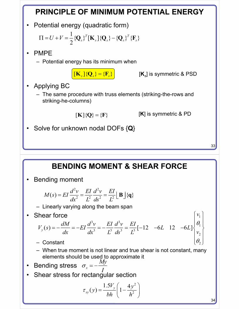
PRINCIPLE OF MINIMUM POTENTIAL ENERGY• Potential energy (quadratic form)
• PMPE– Potential energy has its minimum when
• Applying BC– The same procedure with truss elements (striking-the-rows and
striking-he-columns)
• Solve for unknown nodal DOFs {Q}
1{ } [ ]{ } { } { }2
T Ts s s s sU V� � � �Q K Q Q F
[ ]{ } { }s s s�K Q F
[ ]{ } { }�K Q F
[Ks] is symmetric & PSD
[K] is symmetric & PD
34
BENDING MOMENT & SHEAR FORCE• Bending moment
– Linearly varying along the beam span
• Shear force
– Constant– When true moment is not linear and true shear is not constant, many
elements should be used to approximate it
• Bending stress• Shear stress for rectangular section
2 2
2 2 2 2( ) { }d v EI d v EIM s EIdx L ds L
� � � � �� �B q
13 3
13 3 3 3
2
2
( ) [ 12 6 12 6 ]y
vdM d v EI d v EIV s EI L L
vdx dx L ds L
� ! !! !� � � � � � � � � � " #! !! !$ %
xMyI
� � �
2
2
1.5 4( ) 1yxy
V yybh h
�� �
� �� �� �
35
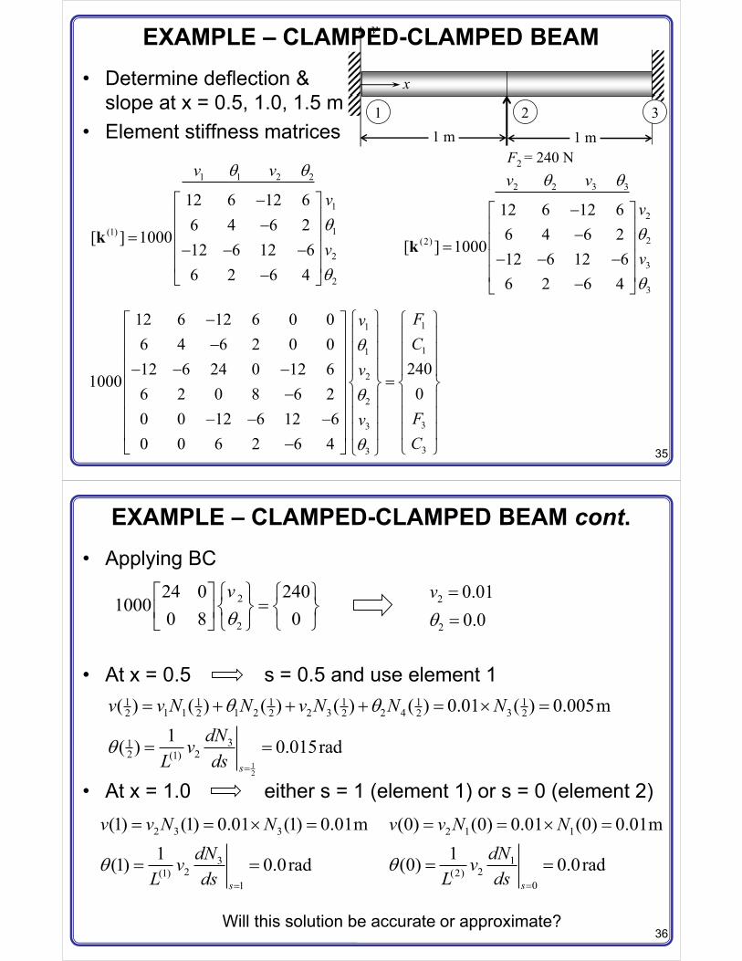
EXAMPLE – CLAMPED-CLAMPED BEAM• Determine deflection &
slope at x = 0.5, 1.0, 1.5 m • Element stiffness matrices
F2 = 240 N
y
x
1 21 m
31 m
1 1 2 2
1
1(1)
2
2
12 6 12 66 4 6 2
[ ] 100012 6 12 66 2 6 4
v v
v
v
�( )� ��� ��� � �� �� ��� �
k
2 2 3 3
2
2(2)
3
3
12 6 12 66 4 6 2
[ ] 100012 6 12 66 2 6 4
v v
v
v
�( )� ��� ��� � �� �� ��� �
k
11
11
2
2
33
33
12 6 12 6 0 06 4 6 2 0 0
24012 6 24 0 12 61000
06 2 0 8 6 20 0 12 6 12 60 0 6 2 6 4
FvC
v
FvC
� � � ( )! ! ! !� �� ! ! ! !� �! ! ! !� � �� �
�" # " #� �� ! ! ! !� �! ! ! !� �� � �! ! ! !� ��� � $ %$ %
36
EXAMPLE – CLAMPED-CLAMPED BEAM cont.• Applying BC
• At x = 0.5 s = 0.5 and use element 1
• At x = 1.0 either s = 1 (element 1) or s = 0 (element 2)
2
2
24 0 2401000
0 8 0v� ( ) �
�" # " #� �� � $ %$ %
2
2
0.010.0
v
��
12
1 1 1 1 1 11 1 1 2 2 3 2 4 32 2 2 2 2 2
3122 (1)
( ) ( ) ( ) ( ) ( ) 0.01 ( ) 0.005m1( ) 0.015rad
s
v v N N v N N NdNv
L ds
�
� � � �
� �
2 3 3
32(1)
1
(1) (1) 0.01 (1) 0.01m1(1) 0.0rad
s
v v N NdNv
L ds
�
� � � �
� �
2 1 1
12(2)
0
(0) (0) 0.01 (0) 0.01m1(0) 0.0rad
s
v v N NdNv
L ds
�
� � � �
� �
Will this solution be accurate or approximate?
37
EXAMPLE – CANTILEVERED BEAM• One beam element• No assembly required• Element stiffness
• Work-equivalent nodal forces
C = –50 N-m
p0 = 120 N/m
EI = 1000 N-m2
1
1
2
2
12 6 12 66 4 6 2
[ ] 100012 6 12 66 2 6 4
s
v
v
�( )� ��� ��� � �� �� ��� �
K
2 31
2 3110 02 30
22 3
2
1/ 2 601 3 2/12 10( 2 )
1/ 2 603 2/12 10( )
e
e
e
e
F s sC Ls s s L
p L ds p LF s sC Ls s L
� � � � � ! !! ! ! ! ! !� ! ! ! ! ! ! ! !� � �" # " # " # " #
�! ! ! ! ! ! ! !! ! ! ! ! ! ! !� �� $ % $ %$ % $ %
�
L = 1m
38
EXAMPLE – CANTILEVERED BEAM cont.• FE matrix equation
• Applying BC
• Deflection curve:• Exact solution:
1 1
1 1
2
2
12 6 12 6 606 4 6 2 10
100012 6 12 6 606 2 6 4 10 50
v FC
v
� � ( ) � ! !� � ! !� ! ! ! !� � �" # " #� � �� � ! ! ! !� � ! ! ! !� � �� � $ %$ %
2
2
12 6 601000
6 4 60v
� � ( ) � �" # " #� �� �� � $ %$ %
2
2
0.010.03
v
� �� �
m
rad
33 4( ) 0.01 ( ) 0.03 ( ) 0.01v s N s N s s� � � � �4 3 2( ) 0.005( 4 )v x x x x� �
39
EXAMPLE – CANTILEVERED BEAM cont.• Support reaction (From assembled matrix equation)
• Bending moment
• Shear force
� �� �
2 2 1
2 2 1
1000 12 6 60
1000 6 2 10
v F
v C
� �
� � 1
1
120 N10 N m
FC
� �� � �
& '
2
1 1 2 22
( ) { }
( 6 12 ) ( 4 6 ) (6 12 ) ( 2 6 )
1000[ 0.01(6 12 ) 0.03( 2 6 )]60 N m
EIM sLEI s v L s s v L sL
s ss
� � �� �
� � � � �
� � � � � � � �
B q
& '1 1 2 23 12 6 12 6
1000[ 12 ( 0.01) 6( 0.03)]60 N
yEIV v L v LL
� � �
� � � � � ��
40
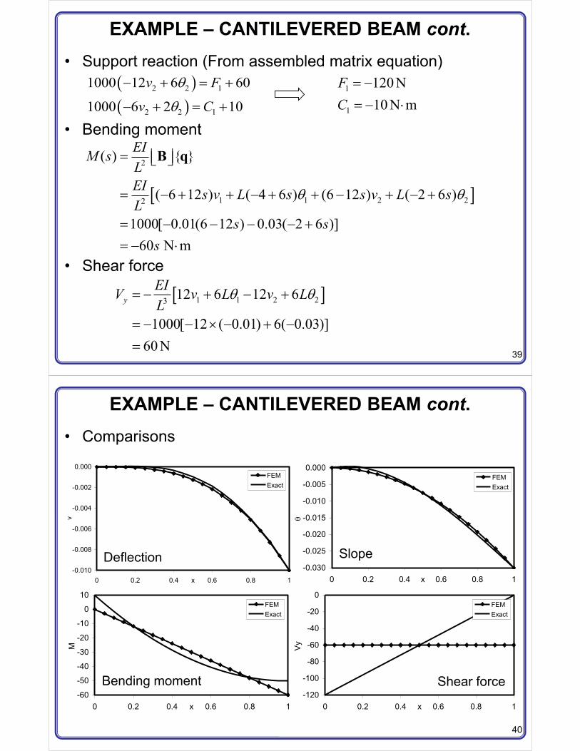
EXAMPLE – CANTILEVERED BEAM cont.• Comparisons
-0.010
-0.008
-0.006
-0.004
-0.002
0.000
0 0.2 0.4 0.6 0.8 1x
v
FEMExact
-0.030
-0.025
-0.020
-0.015
-0.010
-0.005
0.000
0 0.2 0.4 0.6 0.8 1x
FEMExact
-60
-50
-40
-30
-20
-10
0
10
0 0.2 0.4 0.6 0.8 1x
M
FEMExact
-120
-100
-80
-60
-40
-20
0
0 0.2 0.4 0.6 0.8 1x
Vy
FEMExact
Deflection Slope
Bending moment Shear force
41
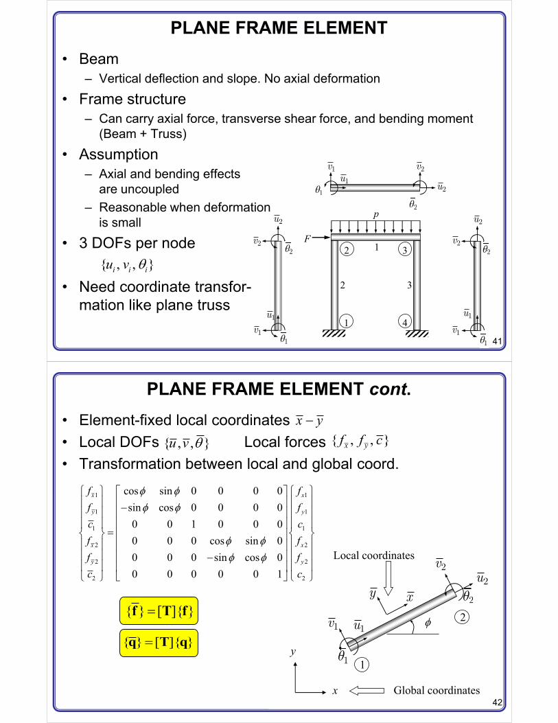
PLANE FRAME ELEMENT• Beam
– Vertical deflection and slope. No axial deformation
• Frame structure– Can carry axial force, transverse shear force, and bending moment
(Beam + Truss)
• Assumption– Axial and bending effects
are uncoupled– Reasonable when deformation
is small
• 3 DOFs per node
• Need coordinate transfor-mation like plane truss
F
p
1
2 3
4
1u2u
1v 2v
11
22
1u
2u
1v
2v
11
22
1u
2u
1v
2v
11
22 1
2 3
{ , , }i i iu v
42
PLANE FRAME ELEMENT cont.• Element-fixed local coordinates• Local DOFs Local forces• Transformation between local and global coord.
1
2*
x
y
Local coordinates
Global coordinates
xy
1u
2u
1v
2v
11
22
x y�{ , , }u v { , , }x yf f c
1 1
1 1
1 1
2 2
2 2
2 2
cos sin 0 0 0 0sin cos 0 0 0 00 0 1 0 0 00 0 0 cos sin 00 0 0 sin cos 00 0 0 0 0 1
x x
y y
x x
y y
f ff fc cf ff fc c
* ** *
* ** *
� � ( )! ! ! !� ��! ! ! !� �! ! ! !� �
�" # " #� �! ! ! !� �! ! ! !� ��! ! ! !� �
� �$ % $ %
{ } [ ]{ }�f T f
{ } [ ]{ }�q T q
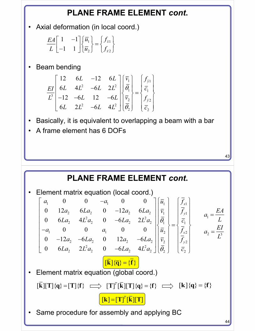
43
PLANE FRAME ELEMENT cont.• Axial deformation (in local coord.)
• Beam bending
• Basically, it is equivalent to overlapping a beam with a bar• A frame element has 6 DOFs
11
22
1 11 1
x
x
fuEAfuL
� � � ( )�" # " #� ��� � $ % $ %
1 12 2
1 13
2 22 2
2 2
12 6 12 66 4 6 212 6 12 6
6 2 6 4
y
y
vL L fL L L L cEI
vL LL fL L L L c
� � � ( )! !! !� �� ! ! ! !� � �" # " #� � �� � ! ! ! !� � ! ! ! !�� � $ % $ %
44
PLANE FRAME ELEMENT cont.• Element matrix equation (local coord.)
• Element matrix equation (global coord.)
• Same procedure for assembly and applying BC
1 1 11
2 2 2 2 112 2
2 2 2 2 11
1 1 22
2 2 2 2 222 2
2 2 2 2 22
0 0 0 00 12 6 0 12 60 6 4 0 6 2
0 0 0 00 12 6 0 12 60 6 2 0 6 4
x
y
x
y
a a fua La a La fvLa L a La L a c
a a fua La a La fv
La L a La L a c
� � � ( )! ! ! !� �� ! ! ! !� �! ! ! !�� �
�" # " #� �� ! ! ! !� �! ! ! !� �� � �! ! ! !� ��� � $ %$ %
1
2 3
EAaLEIaL
�
�
[ ]{ } { }�k fq
[ ][ ]{ } [ ]{ }�k T q T f [ ] [ ][ ]{ } { }T �T k T q f [ ]{ } { }�k q f
[ ] [ ] [ ][ ]T�k T k T
45
PLANE FRAME ELEMENT cont.• Calculation of element forces
– Element forces can only be calculated in the local coordinate– Extract element DOFs {q} from the global DOFs {Qs}– Transform the element DOFs to the local coordinate– Then, use 1D bar and beam formulas for element forces
– Axial force
– Bending moment
– Shear force
• Other method:
{ } [ ]{ }�q T q
� �2 1AEP u uL
� �
2( ) { }EIM sL
� � �� �B q
+ ,3( ) [ 12 6 12 6 ]yEIV s L LL
� � � � q
1 12 2
1 13
2 22 2
2 2
12 6 12 66 4 6 212 6 12 6
6 2 6 4
y
y
V vL LM L L L LEIV vL LLM L L L L
� �� � ( )! ! ! !� �� �! ! ! !� ��" # " # � � �� �! ! ! !� �! ! ! !�� �$ % $ %