Embed Size (px)
Citation preview

A. 120
FunctionsATyS products are 3 and 4-pole switchesremotely controlled by volt freecontacts (ATyS 3) or automatic transferswitches (ATyS 6).They are a combination of two load-breakswitches mounted back to backelectrically and mechanically interlocked.They provide manual switching or remotecontrolled source inversion or changeoverunder load, of two low voltage powercircuits.
Conformity to standards
General characteristics• Isolation with positive break indication.• On load switching.• Manual emergency operation.• 3 stable positions (I, 0, II) or overlapping
contacts on request (I, I+II, II), for ATyS only.• Padlocking in 0 or in all three positions
(I, 0, II).• AUTO / MANU selector.
�
FunctionsReferencesAccessoriesEnclosed ATySCharacteristicsDimensions
Changeover switches
ATyS63 to 3200 A
SOCOMEC general catalogue
atys
_003
_a_1
_cat
ATyS 3s
atys
_102
_a_1
_cat
ATyS 6m
• IEC 60947-3• EN 60947-3• NBN EN 60947-3• BS EN 60947-3• GB 14048
• IEC 60947-6-1• EN 60947-6-1• NBN EN 60947-6-1• BS EN 60947-6-1• VDE 0660-107
ATyS M 3s
ATyS M 6e
atys
m_0
13_a
_1_c
at
atys
m_0
07_a
_1_c
at
This document is not a contract. SOCOMEC reserves the right to modify featureswithout prior notice in view of continued improvement. 2008 - 2009

A. 121
Changeover switches
ATyS
SOCOMEC general catalogue
1
2
3
4
5
6
7
8
9
9
10
11
12
13
atys
_615
_a_1
_x_c
atat
ysm
_032
_a_1
_x_c
at
1. Backup handle and support (included with device)
2. Handle key interlocking accessories
3. Door protective surround
4. Additional auxiliary contacts
5. Standard device
6. Connecting cable for ATyS D10 or D20remote interfaces (ATyS 6)
7. ATyS D10 or D20 interfaces (ATyS 6)
8. Plug-in optional modules (not for ATyS 3s)
9. Voltage sensing and power supply kit (ATyS 6)
10. Terminal shrouds
11. Bridging bars
12. Mounting spacers
13. Terminal screens
Overview (for further details, please see theinstallation instructions supplied with eachdevice).
IllustrationsATyS M from 63 to 160 A
ATyS from 125 to 3200 A
1
2
3
3
4
5
11
1. ATyS D10 or D20 remote interfaces (ATyS M 6e only)
2. 1 or 2 auxiliary contacts
3. Terminal shrouds
4. Voltage sensing and power supply tap
5. Bridging bars
This document is not a contract. SOCOMEC reserves the right to modify featureswithout prior notice in view of continued improvement. 2008 - 2009

A. 122
�
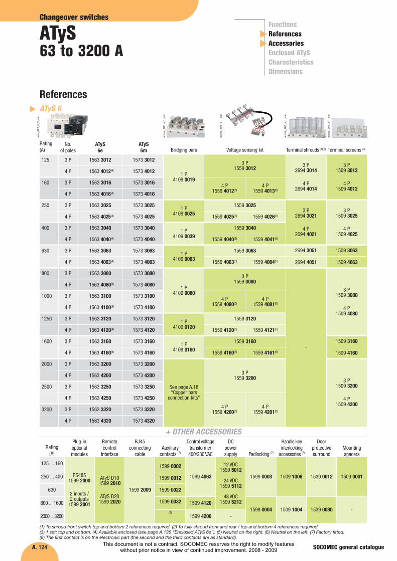
References
Changeover switches
ATyS63 to 3200 A
SOCOMEC general catalogue
FunctionsReferencesAccessoriesEnclosed ATySCharacteristicsDimensions
(1) Power-supply voltage 230 VAC.(2) 2 pieces: top and bottom.(3) 1 contact block for I, 0 and II positions.
atys
m_0
13_a
_2_c
at
�
ATyS 3ATyS M 3
pair1399 4006
63
Rating(A)
No.of poles
ATyS M3s (1)
1309 4006
1309 4016
Bridging bars
4 P 1323 4006
80 4 P 1323 4008
pair2294 4016
1st ACstandard2nd AC
1309 0001
Voltage sensing and power supply tap
Terminal shrouds (2)
Auxiliary contacts (3)
100 4 P 1323 4010
125 4 P 1323 4012
160 4 P 1323 4016
atys
m_0
26_a
_1_c
at
atys
m_0
27_a
_1_c
at
atys
m_0
28_a
_1_c
at
1599 4001
DPS - Double power
supply
atys
_612
_a_1
_cat
(1) To shroud front switch top and bottom 2 references required.(2) 1 contact block for I, 0 and II positions.(3) For ATyS M 6e only.(4) For ATyS M 6s only.
atys
m_0
07_a
_2_c
at
atys
m_0
25_a
_1_c
at
�
ATyS 3ATyS M 6
pair1399 4006
63
Rating(A)
No.of poles
Network (VAC)
1309 4006
1309 4016
Bridging bars
4 P 127 / 230
4 P 230 / 400
80 4 P 127 / 230
pair2294 4016 1309 0001
Voltage sensingand powersupply tap
Terminalshrouds (1)
Auxiliarycontacts (2)
ATyS D101599 2010
ATyS D201599 2020
Remote interface (3)
1359 0000
Sealable cover (4)
ATyS M6s
1353 4006
1354 4006
1353 4008
ATyS M6e
1363 4006
1364 4006
1363 4008
4 P 230 / 400
100 4 P 127 / 230
4 P 230 / 400
1354 4008
1353 4010
1354 4010
1364 4008
1363 4010
1364 4010
125 4 P 127 / 230
4 P 230 / 400
160 4 P 127 / 230
4 P 230 / 400
1353 4012
1354 4012
1353 4016
1354 4016
1363 4012
1364 4012
1363 4016
1364 4016
atys
m_0
26_a
_1_c
at
atys
m_0
27_a
_1_c
at
atys
m_0
28_a
_1_c
at
atys
_565
_c_2
_cat
atys
m_0
43_a
atys
m_0
25_a
_1_c
at
This document is not a contract. SOCOMEC reserves the right to modify featureswithout prior notice in view of continued improvement. 2008 - 2009

A. 123
Changeover switches
ATyS
SOCOMEC general catalogue
(1) To shroud front switch top and bottom 2 references required. (2) To fully shroud front and rear / top and bottom 4 references required. (3) 1 set: top and bottom. (4) Available enclosed (see page A.134 “Enclosed ATyS 3s”). (5) Factory fitted. (6) The first contact is on the electronic part (the second and the third contacts are as standard).
Rating (A)
ATyS 3s
ATyS 3e
125 ... 160
250 ... 400
630
800 ... 1800
125 ... 160
250 ... 400
630
800 ... 1600
2000 ... 3200
1599 4120
1599 4120
1599 4200 -
1599 1002
1599 1012
1599 1022
1599 1032
Plug-in optionalmodules
Auxiliarycontacts (5)
Control voltagetransformer
400/230 VAC
1599 0002
1599 0012
1599 0022
1599 0032(6)
DC powersupply
1599 0004
Padlocking (5)
1509 1004
Handle key interlocking
accessories (5)
1529 0080
Door protectivesurround
-
Mountingspacers
DPS - Doublepower supply
-1599 4063
1599 4063
1599 0003 1509 1006 1529 0012 1509 00011599 4001
1509 00011539 00121509 10061599 0003
References
1599 0004 1509 1004 -1539 0080
800 3 P
4 P
1000 3 P
4 P
1523 3080
1523 4080(4)
1523 3100
1523 4100(4)
1250 3 P
4 P
1600 3 P
4 P
1523 3120
1523 4120(4)
1523 3160
1523 4160(4)
1800 3 P
4 P
1523 3180
1523 4180
1533 3080
1533 4080
1533 3100
1533 4100
1533 3120
1533 4120
1533 3160
1533 4160
-
-
2000 3 P
4 P
-
-
1533 3200
1533 4200
2500 3 P
4 P
-
-
1533 3250
1533 4250
3200 3 P
4 P
-
-
1533 3320
1533 4320
1 P
4109 0120
3 P1509 3160
4 P1509 4160
3 P1509 3200
4 P1509 4200
1 P4109 0080
1 P4109 0160
See page A.126 “Copper bars
connection kits”
3 P1509 3080
4 P1509 4080
-
Rating (A)
No.of poles
125
160
250
3 P
4 P
3 P
4 P
3 P
4 P
400 3 P
4 P
630 3 P
4 P
1523 3012
1523 4012(4)
1523 3016
1523 4016(4)
1523 3025
1523 4025(4)
1523 3040
1523 4040(4)
1523 3063
1523 4063(4)
ATyS 3s
atys
_003
_a_3
_cat
acce
s_20
5_a_
1_ca
t
acce
s_20
6_a_
1_ca
t
acce
s_20
7_a_
1_ca
t
1533 3012
1533 4012
1533 3016
1533 4016
1533 3025
1533 4025
1533 3040
1533 4040
1533 3063
1533 4063
ATyS 3e
1 P4109 0019
3 P1509 3012
4 P1509 4012
3 P2694 3014
4 P2694 4014
Bridging bars Terminal shrouds (1)(2) Terminal screens (3)
1 P4109 0025
1 P4109 0039
1 P4109 0063
3 P2694 3021
4 P2694 4021
2694 3051
2694 4051
3 P1509 3025
4 P1509 4025
1509 3063
1509 4063
�
ATyS 3ATyS 3
RS4851599 2000
2 inputs / 2 outputs
1599 2001
12 VDC1599 5012
24 VDC1599 5112
48 VDC1599 5212 -
+ OTHER ACCESSORIES
This document is not a contract. SOCOMEC reserves the right to modify featureswithout prior notice in view of continued improvement. 2008 - 2009
A. 124
References
��
Changeover switches
ATyS63 to 3200 A
FunctionsReferencesAccessoriesEnclosed ATySCharacteristicsDimensions
SOCOMEC general catalogue
800 3 P
4 P
1000 3 P
4 P
1563 3080
1563 4080(4)
1563 3100
1563 4100(4)
1250 3 P
4 P
1600 3 P
4 P
1563 3120
1563 4120(4)
1563 3160
1563 4160(4)
1573 3080
1573 4080
1573 3100
1573 4100
1573 3120
1573 4120
1573 3160
1573 4160
2000 3 P
4 P
1563 3200
1563 4200
1573 3200
1573 4200
2500 3 P
4 P
1563 3250
1563 4250
1573 3250
1573 4250
3200 3 P
4 P
1563 3320
1563 4320
1573 3320
1573 4320
1 P4109 0120
4 P1559 4080(5)
4 P1559 4081(6)
1 P4109 0160
1559 4120(5) 1559 4121(6)
1559 4160(5) 1559 4161(6)
1509 3160
1509 4160
3 P1509 3080
4 P1509 4080
Rating (A)
125 ... 160
250 ... 400
630
800 ... 1600
2000 ... 3200
Plug-in optionalmodules
Remote control
interface
RJ45 connecting
cable
1599 0002
1599 0012
1599 0022
1599 0032
(8)
Auxiliarycontacts (7)
1599 4120
1599 4200 -
Control voltagetransformer400/230 VAC Padlocking (7)
Handle key interlocking
accessories (7)
Door protectivesurround
Mountingspacers
4 P1559 4200(5)
4 P1559 4201(6)
(1) To shroud front switch top and bottom 2 references required. (2) To fully shroud front and rear / top and bottom 4 references required. (3) 1 set: top and bottom. (4) Available enclosed (see page A.135 “Enclosed ATyS 6e”). (5) Neutral on the right. (6) Neutral on the left. (7) Factory fitted. (8) The first contact is on the electronic part (the second and the third contacts are as standard).
1 P4109 0080
DC power supply
3 P1509 3200
4 P1509 4200
1509 00011539 00121509 10061599 00031599 4063
Rating (A)
No.of poles
125
160
250
3 P
4 P
3 P
4 P
3 P
4 P
400 3 P
4 P
630 3 P
4 P
1563 3012
1563 4012(4)
1563 3016
1563 4016(4)
1563 3025
1563 4025(4)
1563 3040
1563 4040(4)
1563 3063
1563 4063(4)
ATyS 6e
atys
_097
_b_2
_cat
1573 3012
1573 4012
1573 3016
1573 4016
1573 3025
1573 4025
1573 3040
1573 4040
1573 3063
1573 4063
ATyS 6m
4 P1559 4012(5)
4 P1559 4013(6)
Bridging bars Voltage sensing kit
1 P4109 0025
1 P4109 0039
1 P4109 0063
1559 4025(5) 1559 4026(6)
�
Commutateur VM1 I-0-IIATyS 6
1559 4040(5) 1559 4041(6)
1559 4063(5) 1559 4064(6)
3 P2694 3014
4 P2694 4014
Terminal shrouds (1)(2)
3 P2694 3021
4 P2694 4021
2694 3051
2694 4051
3 P1509 3012
4 P1509 4012
Terminal screens (3)
3 P1509 3025
4 P1509 4025
1509 3063
1509 4063
3 P1559 3012
1559 3025
1559 3040
1559 3063
1 P4109 0019
acce
s_20
5_a_
1_ca
t
acce
s_60
6_a_
1_ca
t
acce
s_20
6_a_
1_ca
t
acce
s_20
7_a_
1_ca
t
3 P1559 3200
1559 3160
1559 3120
3 P1559 3080
See page A.18 “Copper bars
connection kits”
-
12 VDC1599 5012
24 VDC1599 5112
48 VDC1599 5212
1599 0004 1509 1004 1539 0080 -
1599 2009
ATyS D101599 2010
ATyS D201599 2020
RS4851599 2000
2 inputs / 2 outputs
1599 2001
+ OTHER ACCESSORIES
This document is not a contract. SOCOMEC reserves the right to modify featureswithout prior notice in view of continued improvement. 2008 - 2009
A. 125
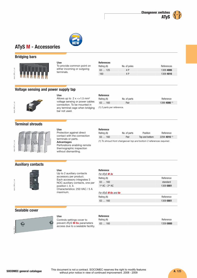
ATyS M - Accessories
Changeover switches
ATyS
SOCOMEC general catalogue
Bridging bars
atys
m_0
25_a
_1_c
at
ReferencesRating (A) No. of poles References
63 … 125160
4 P4 P
1309 40061309 4016
UseTo provide common point oneither incoming or outgoingterminals.
Voltage sensing and power supply tapReferenceUse
Allows up to 2 x <=1.5 mm2
voltage sensing or power cablesconnection. To be mounted inany terminal cage when bridgingbar not used.
Rating (A) Reference
63 … 160
No. of parts
Pair 1399 4006 (1)
atys
m_0
26_a
_1_c
at
Rating (A) Reference
63 … 160 2294 4016 (1)
Terminal shrouds
atys
m_0
27_a
_1_c
at
ReferenceNo. of parts Position
Pair Top and bottom
UseProtection against directcontact with the connectionterminals or parts.AdvantagesPerforations enabling remotethermographic inspectionwithout dismantling.
Auxiliary contacts
atys
m_0
28_a
_1_c
at
ReferenceUseUp to 2 auxiliary contactsaccessory per product.Each accessory integrates 3NOC auxiliary contacts, one perposition I, 0, II.Characteristics: 250 VAC / 5 Amaximum.
Rating (A) Reference
63 … 160 standard
Reference
1359 0000
Sealable coverReferenceRating (A)
63 … 160
UseControls settings cover toprevent ATyS M 6s parametersaccess due to a sealable facility.
atys
m_0
43_a
(1) 2 parts per reference.
(1) To shroud front changeover top and bottom 2 references required.
For ATyS M 3s
Rating (A) Reference
63 … 160 1309 0001
For ATyS M 6s and 6e
1st AC - 2nd AC 1309 0001
This document is not a contract. SOCOMEC reserves the right to modify featureswithout prior notice in view of continued improvement. 2008 - 2009

A. 126
�
Changeover switches
ATyS63 to 3200 A
FunctionsReferencesAccessoriesEnclosed ATySCharacteristicsDimensions
SOCOMEC general catalogue
ATyS - Accessories
Bridging bars
acce
s_20
5_a_
1_ca
tac
ces_
041_
a_1_
cat
ReferencesRating (A) No. of poles Section (mm) References
125 … 160 1 P 20 x 2.5 4109 0019250 1 P 25 x 2.5 4109 0025400 1 P 32 x 5 4109 0039630 1 P 50 x 5 4109 0063800 … 1000 1 P 50 x 6 4109 00801250 1 P 60 x 8 4109 01201600 … 1800 1 P 90 x 10 4109 0160
UseTo provide common point oneither incoming or outgoingterminals.
Copper bars connection kits
Fig.1
B
A
acce
s_22
6_c_
1_x_
cat
Fig.2
D
A
C
acce
s_22
8_b_
1_x_
cat
Fig.3
E
A
C
B
acce
s_23
0_b_
1_x_
cat
ReferencesTop or bottom flat connection - Fig. 1
Rating (A) References
2000 … 2500
32003200
2699 1200
standard2699 1200
Part
Bolt set - part B
Bolt set - part B
Qty to order per pole (1)
2
/2
UseTo allow:- connection between the two
power terminals from a samepole for 2000 to 3200 A ratings(Fig. 1 and Fig 2),
- top or bottom bridgingconnection (Fig. 3).
For 3200 A rating, theconnection piece (part A) aredelivered bridged from factory.Bolt sets must be orderedseparately.
DimensionsSee page A.145, for connectionkit assembly.
Technical notice for thesespecific accessories isdownloadable fromwww.socomec.com
2000 … 2500 2619 12002
Top or bottom edgewise connection - Fig. 2
Rating (A) References
2000 … 2500
3200
3200
2639 1200 (2)
standard
2639 1200 (2)
Part
Right angle - part D
Right angle - part D
Qty to order per pole (1)
2
/
23200 2629 1200 (2)T piece - part C 2
2000 … 2500 2619 120022000 … 2500 T piece - part C 2 2629 1200 (2)
Top or bottom bridging connection - Fig. 3
Rating (A) References
2000 … 2500
3200
3200
4109 0250 (2)
standard
4109 0320 (2)
Part
Bar - part E
Bar - part E
Qty to order per pole (1)
1
/
13200 2699 1200Bolt set - part B 2
3200 2629 1200 (2)T piece - part C 1
2000 … 2500 2619 120022000 … 2500 Bolt set - part B 2
2000 … 2500 2629 1200 (2)T piece - part C 1
(1) Example for 3-pole device equipped top only: order 3 times the quantities.(2) Bolt set is provided with the accessories.
2699 1200
Connection piece - part A
Connection piece - part A
Connection piece - part A
Connection piece - part A
Connection piece - part A
Connection piece - part A
This document is not a contract. SOCOMEC reserves the right to modify featureswithout prior notice in view of continued improvement. 2008 - 2009

A. 127
Changeover switches
ATyS
SOCOMEC general catalogue
ATyS - Accessories
Voltage sensing and power supply kit
atys
_606
_a_1
_cat
atys
_603
_a_1
_cat
ReferencesFor ATyS 6 - 3 pole
Rating (A) References
125 … 160 1559 3012250 1559 3025400 1559 3040630 1559 3063800 … 1000 1559 30801250 1559 31201600 1559 31602000 … 3200 1559 3200
For ATyS 6 - 4 pole
Rating (A)
Neutral on the right Neutral on the left
References References
125 … 160 1559 4012 1559 4013
1250 1559 4120 1559 41211600 1559 4160 1559 4161
250 1559 4025 1559 4026400 1559 4040 1559 4041630 1559 4063 1559 4064800 … 1000 1559 4080 1559 4081
2000 … 3200 1559 4200 1559 4201
UseFor ATyS 6 power supply andvoltage measurement (4 wires,three phases).Routing of the conductors is controlled, which means thatno specific protective device is necessary for theseconnections.The kit can be fitted on the topor the bottom of the switch.NB: the 3-pole version does notintegrate the power supply.
From 125 to 630 A
From 800 to 3200 A
Plug-in optional modules
atys
_016
_a_1
_cat
ReferencesDescription of accessories References
COM RS485 (No. 1) 1599 20002 inputs/2 outputs (No. 2) 1599 2001
UseNo. 1: COM module control andstate feedback of the changeoverswitch via a 2 or 3-wire RS485link with JBUS/MODBUSprotocol® and transmissionspeed up to 38,400 baud.No. 2: module with 2 inputs/2 outputs• For ATyS 3e:
2 inputs: changeover control +backup network availability ; 2 outputs: a load shedderrelay + fault relay.
• For ATyS 6e and 6m: 2 inputs/2 outputs, programmable.
This document is not a contract. SOCOMEC reserves the right to modify featureswithout prior notice in view of continued improvement. 2008 - 2009

A. 128
�
Changeover switches
ATyS63 to 3200 A
FunctionsReferencesAccessoriesEnclosed ATySCharacteristicsDimensions
SOCOMEC general catalogue
ATyS - Accessories
Terminal screens
acce
s_20
7_a_
1_ca
t
References
Rating (A) No. of poles Position References
125 … 160 3 P top or bottom 1509 3012125 … 160 4 P top or bottom 1509 4012250 … 400 3 P top or bottom 1509 3025250 … 400 4 P top or bottom 1509 4025630 3 P top or bottom 1509 3063630 4 P top or bottom 1509 4063800 … 1250 3 P top or bottom 1509 3080800 … 1250 4 P top or bottom 1509 40801600 … 1800 3 P top or bottom 1509 31601600 … 1800 4 P top or bottom 1509 41602000 … 3200 3 P top or bottom 1509 32002000 … 3200 4 P top or bottom 1509 4200
UseTop or bottom protectionagainst direct contacts with theconnection terminals or parts.
Inter phase barriers
acce
s_03
6_a_
1_ca
t
References
Rating (A) No. of poles References
125 … 160 3 P 2998 0033
125 … 160 4 P 2998 0034
250 … 400 3 P 2998 0023
250 … 400 4 P 2998 0024
630 3 P 2998 0013
630 4 P 2998 0014
800 … 3200 3/4 P standard
UseSafety isolating separationbetween the terminals, essentialfor use at 690 VAC or in a dustyatmosphere.The terminal shrouds alsoprovide phase separation forATyS from 125 to 630 A.
Terminal shrouds
acce
s_20
6_a_
1_ca
t
References
Rating (A) No. ofpoles Position References
125 … 160 3 P top / bottom / front (I) / rear (II) 2694 3014(1)(2)
125 … 160 4 P top / bottom / front (I) / rear (II) 2694 4014(1)(2)
250 … 400 3 P top / bottom / front (I) / rear (II) 2694 3021(1)(2)
250 … 400 4 P top / bottom / front (I) / rear (II) 2694 4021(1)(2)
630 3 P top / bottom / front (I) / rear (II) 2694 3051(1)(2)
630 4 P top / bottom / front (I) / rear (II) 2694 4051(1)(2)
(1) To shroud front switch top and bottom 2 references required.(2) To fully shroud front and rear / top and bottom 4 references required.
UseProtection against directcontact with the connectionterminals or parts.AdvantagesPerforations enabling remotethermographic inspectionwithout dismantling.
This document is not a contract. SOCOMEC reserves the right to modify featureswithout prior notice in view of continued improvement. 2008 - 2009
A. 129
Changeover switches
ATyS
SOCOMEC general catalogue
ATyS - Accessories
Padlocking in the 3 positions I-0-II
Aty
s_12
5_a_
1_ca
t
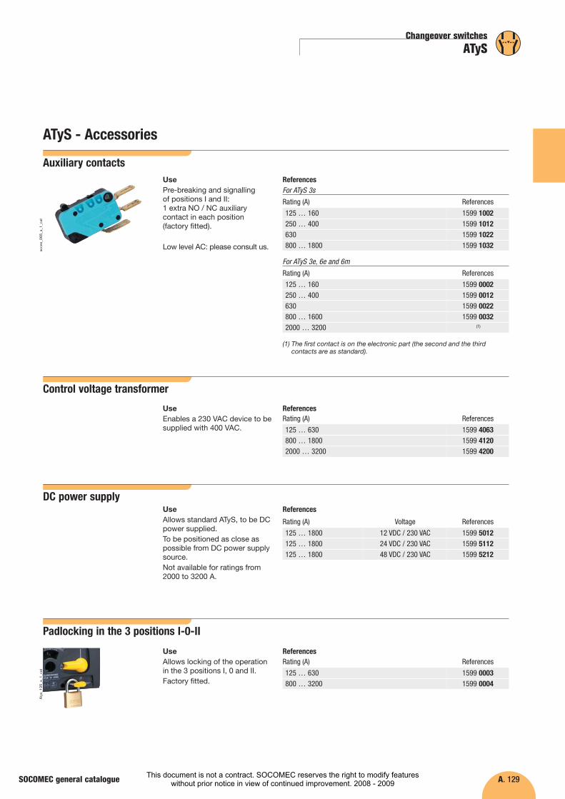
ReferencesRating (A) References
125 … 630 1599 0003800 … 3200 1599 0004
UseAllows locking of the operationin the 3 positions I, 0 and II. Factory fitted.
Control voltage transformer
ReferencesRating (A) References
125 … 630 1599 4063800 … 18002000 … 3200
1599 41201599 4200
UseEnables a 230 VAC device to besupplied with 400 VAC.
Auxiliary contacts
acce
s_06
5_a_
1_ca
t
ReferencesFor ATyS 3s
Rating (A) References
125 … 160 1599 1002250 … 400 1599 1012630 1599 1022800 … 1800 1599 1032
For ATyS 3e, 6e and 6m
Rating (A) References
125 … 160 1599 0002250 … 400 1599 0012630 1599 0022800 … 1600 1599 00322000 … 3200 (1)
UsePre-breaking and signalling of positions I and II: 1 extra NO / NC auxiliarycontact in each position (factory fitted).
Low level AC: please consult us.
DC power supplyReferences
Rating (A) Voltage References
125 … 1800 1599 5012125 … 1800 1599 5112125 … 1800 1599 5212
UseAllows standard ATyS, to be DCpower supplied.To be positioned as close aspossible from DC power supplysource.Not available for ratings from2000 to 3200 A.
12 VDC / 230 VAC24 VDC / 230 VAC48 VDC / 230 VAC
(1) The first contact is on the electronic part (the second and the thirdcontacts are as standard).
This document is not a contract. SOCOMEC reserves the right to modify featureswithout prior notice in view of continued improvement. 2008 - 2009

A. 130
�
Changeover switches
ATyS63 to 3200 A
FunctionsReferencesAccessoriesEnclosed ATySCharacteristicsDimensions
SOCOMEC general catalogue
ATyS - Accessories
Mounting spacers
atys
_009
_a_1
_cat
ReferenceRating (A) Description of accessories Reference
125 … 630 1 set of 2 spacers 1509 0001
UseRaises the device’s terminals 10 mm away from the bottom of the enclosure or frame onwhich the device is mounted.This may also be used toreplace the original mountingspacers.
Handle key interlocking accessories
Aty
s_10
1_a_
1_ca
t
ReferencesRating (A) References
125 … 630 1509 1006800 … 3200 1509 1004
UseLocking the electrical controland the backup control inposition 0 using a RONISEL11AP lock.Factory fitted.As standard, locking in position 0.Optional padlocking in 3positions: 0, I and II.
Door protective surround
atys
_595
_a_1
_cat
ReferencesFor ATyS 3s
Rating (A) References
125 … 630 1529 0012800 … 1800 1529 0080
For ATyS 3e, 6e and 6m
Rating (A) References
125 … 630 1539 0012800 … 3200 1539 0080
UseDoor finishing surround forprotecting ATyS application.
�
This document is not a contract. SOCOMEC reserves the right to modify featureswithout prior notice in view of continued improvement. 2008 - 2009
A. 131
Changeover switches
ATyS
SOCOMEC general catalogue
ATyS - Accessories
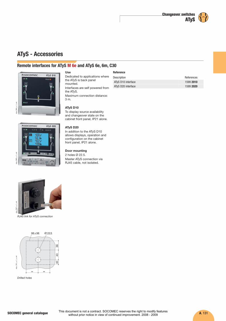
Remote interfaces for ATyS M 6e and ATyS 6e, 6m, C30
atys
_564
_c_1
_cat
atys
_565
_c_1
_cat
Reference
Description References
ATyS D10 interfaceATyS D20 interface
1599 20101599 2020
UseDedicated to applications wherethe ATyS is back panelmounted.Interfaces are self powered fromthe ATyS. Maximum connection distance:3 m.
ATyS D10To display source availabilityand changeover state on thecabinet front panel, IP21 alone.
ATyS D20In addition to the ATyS D10allows displays, operation andconfiguration on the cabinetfront panel, IP21 alone.
Door mounting2 holes Ø 22.5.Master ATyS connection viaRJ45 cable, not isolated.
Drilled holes
atys
_597
_a_1
_cat
Ø 22.5
4036
20
= =
96 x 96
atys
_161
_a_1
_x_c
at
RJ45 link for ATyS connection
This document is not a contract. SOCOMEC reserves the right to modify featureswithout prior notice in view of continued improvement. 2008 - 2009
A. 132
�
Changeover switches
ATyS63 to 3200 A
FunctionsReferencesAccessoriesEnclosed ATySCharacteristicsDimensions
SOCOMEC general catalogue
ATyS - Accessories
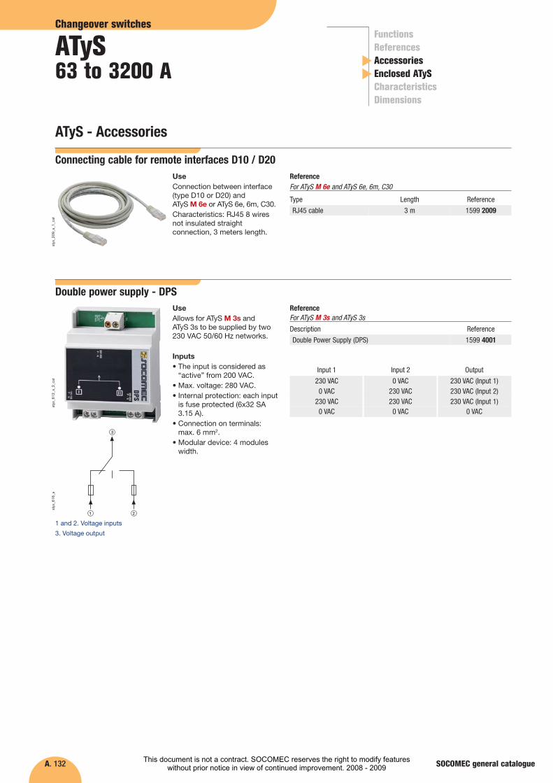
Double power supply - DPSReference
Description Reference
Double Power Supply (DPS) 1599 4001
Input 1 Output
230 VAC 230 VAC (Input 1)
Input 2
0 VAC0 VAC 230 VAC (Input 2)230 VAC
230 VAC 230 VAC (Input 1)230 VAC0 VAC 0 VAC0 VAC
UseAllows for ATyS M 3s and ATyS 3s to be supplied by two230 VAC 50/60 Hz networks.
Inputs• The input is considered as
“active” from 200 VAC.• Max. voltage: 280 VAC.• Internal protection: each input
is fuse protected (6x32 SA3.15 A).
• Connection on terminals: max. 6 mm2.
• Modular device: 4 moduleswidth.
atys
_612
_a_2
_cat
3
21
atys
_616
_a
1 and 2. Voltage inputs
3. Voltage output
For ATyS M 3s and ATyS 3s
Connecting cable for remote interfaces D10 / D20UseConnection between interface(type D10 or D20) and ATyS M 6e or ATyS 6e, 6m, C30.Characteristics: RJ45 8 wiresnot insulated straightconnection, 3 meters length.
atys
_209
_a_1
_cat
Type Reference
RJ45 cable
Length
3 m 1599 2009
ReferenceFor ATyS M 6e and ATyS 6e, 6m, C30
�
This document is not a contract. SOCOMEC reserves the right to modify featureswithout prior notice in view of continued improvement. 2008 - 2009
A. 133
Changeover switches
ATyS
SOCOMEC general catalogue
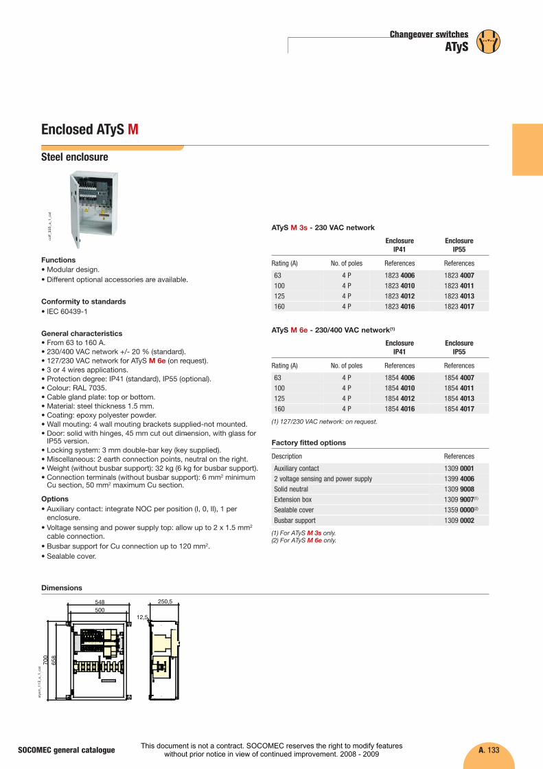
Enclosed ATyS M
Steel enclosure
Functions• Modular design.• Different optional accessories are available.
Conformity to standards• IEC 60439-1
General characteristics• From 63 to 160 A.• 230/400 VAC network +/- 20 % (standard).• 127/230 VAC network for ATyS M 6e (on request).• 3 or 4 wires applications.• Protection degree: IP41 (standard), IP55 (optional).• Colour: RAL 7035.• Cable gland plate: top or bottom.• Material: steel thickness 1.5 mm.• Coating: epoxy polyester powder.• Wall mouting: 4 wall mouting brackets supplied-not mounted.• Door: solid with hinges, 45 mm cut out dimension, with glass for
IP55 version.• Locking system: 3 mm double-bar key (key supplied).• Miscellaneous: 2 earth connection points, neutral on the right.• Weight (without busbar support): 32 kg (6 kg for busbar support).• Connection terminals (without busbar support): 6 mm2 minimum
Cu section, 50 mm2 maximum Cu section.
Options• Auxiliary contact: integrate NOC per position (I, 0, II), 1 per
enclosure.• Voltage sensing and power supply top: allow up to 2 x 1.5 mm2
cable connection.• Busbar support for Cu connection up to 120 mm2.• Sealable cover.
coff_
335_
a_1_
cat
Rating (A) References
Dimensions
ATyS M 3s - 230 VAC network
500548
658
700
250,5
12,5
atys
m_1
13_a
_1_c
at
63 1823 4007
160 1823 4017
No. of poles
4 P
4 P
100 1823 40114 P125 1823 40134 P
References
Enclosure IP41
Enclosure IP55
1823 4006
1823 4016
1823 40101823 4012
Rating (A) References
ATyS M 6e - 230/400 VAC network(1)
63 1854 4007
160 1854 4017
No. of poles
4 P
4 P
100 1854 40114 P125 1854 40134 P
References
Enclosure IP41
Enclosure IP55
1854 4006
1854 4016
1854 40101854 4012
Description References
Factory fitted options
Auxiliary contact 1309 00012 voltage sensing and power supply 1399 4006Solid neutral 1309 9008Extension boxSealable cover 1359 0000(2)
1309 9007(1)
Busbar support 1309 0002
(1) 127/230 VAC network: on request.
(1) For ATyS M 3s only.(2) For ATyS M 6e only.
This document is not a contract. SOCOMEC reserves the right to modify featureswithout prior notice in view of continued improvement. 2008 - 2009
A. 134
�
Changeover switches
ATyS63 to 3200 A
FunctionsReferencesAccessoriesEnclosed ATySCharacteristicsDimensions
SOCOMEC general catalogue
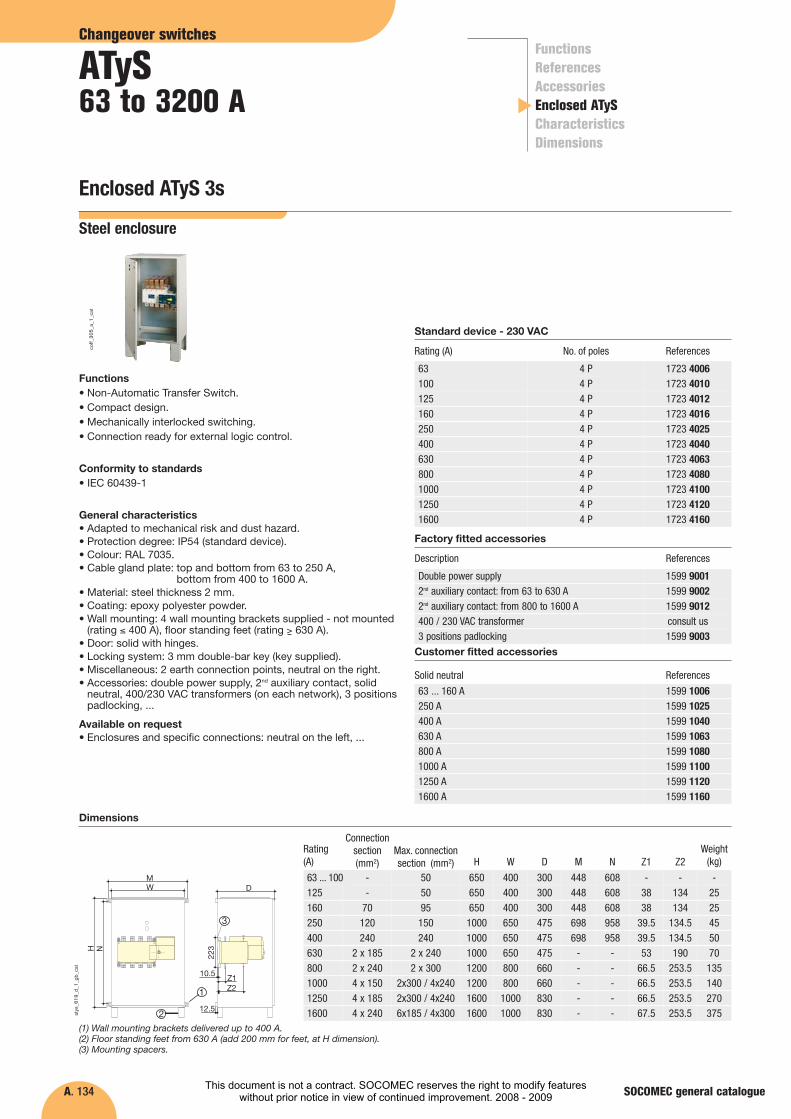
Enclosed ATyS 3s
Steel enclosure
Functions• Non-Automatic Transfer Switch.• Compact design.• Mechanically interlocked switching.• Connection ready for external logic control.
Conformity to standards• IEC 60439-1
General characteristics• Adapted to mechanical risk and dust hazard.• Protection degree: IP54 (standard device).• Colour: RAL 7035.• Cable gland plate: top and bottom from 63 to 250 A,
bottom from 400 to 1600 A.• Material: steel thickness 2 mm.• Coating: epoxy polyester powder.• Wall mounting: 4 wall mounting brackets supplied - not mounted
(rating ≤ 400 A), floor standing feet (rating > 630 A).• Door: solid with hinges.• Locking system: 3 mm double-bar key (key supplied).• Miscellaneous: 2 earth connection points, neutral on the right.• Accessories: double power supply, 2nd auxiliary contact, solid
neutral, 400/230 VAC transformers (on each network), 3 positionspadlocking, ...
Available on request• Enclosures and specific connections: neutral on the left, ...
Rating (A) References
Dimensions
coff_
305_
a_1_
cat
Standard device - 230 VAC
WM
H N
223
12.5
D
10.5Z1Z2
3
1
2atys
_619
_d_1
_gb_
cat
(1) Wall mounting brackets delivered up to 400 A.(2) Floor standing feet from 630 A (add 200 mm for feet, at H dimension).(3) Mounting spacers.
Rating (A)
Max. connectionsection (mm2)
Weight(kg)
50 -
160 95 25250 150 45400 240 50630 2 x 240 70800 2 x 300 1351000 2x300 / 4x240 1401250 2x300 / 4x240 2701600 6x185 / 4x300 375
Z2
-
134134.5134.5190
253.5253.5253.5253.5
Z1
-
3839.539.553
66.566.566.567.5
N
608
608958958
-----
M
448
448698698
-----
D
300
300475475475660660830830
W
400
40065065065080080010001000
H
650
6501000100010001200120016001600
Connectionsection(mm2)
-
70120240
2 x 1852 x 2404 x 1504 x 1854 x 240
125 50 2513438608448300400650-
63 1723 4006
160 1723 4016250 1723 4025400 1723 4040630 1723 4063800 1723 40801000 1723 41001250 1723 41201600 1723 4160
No. of poles
4 P
4 P4 P4 P4 P4 P4 P4 P4 P
100 1723 40104 P125 1723 40124 P
Solid neutral References
Customer fitted accessories
63 ... 160 A 1599 1006250 A 1599 1025400 A 1599 1040630 A 1599 1063800 A 1599 10801000 A 1599 11001250 A 1599 11201600 A 1599 1160
Description References
Factory fitted accessories
Double power supply 1599 90012nd auxiliary contact: from 63 to 630 A 1599 90022nd auxiliary contact: from 800 to 1600 A 1599 9012400 / 230 VAC transformer3 positions padlocking 1599 9003
consult us
63 ... 100
This document is not a contract. SOCOMEC reserves the right to modify featureswithout prior notice in view of continued improvement. 2008 - 2009

A. 135
Changeover switches
ATyS
SOCOMEC general catalogue
Enclosed ATyS 6e
Steel enclosure
Functions• Automatic Transfer Switch - ATS.• Compact design.• Mechanically interlocked switching.• Connection ready for external logic control.
Conformity to standards• IEC 60947-6-1• IEC 60439-1
General characteristics• Adapted to mechanical risk and dust hazard.• Protection degree: IP54 (standard device).• Colour: RAL 7035.• Cable gland plate: top and bottom from 63 to 250 A,
bottom from 400 to 1600 A.• Material: steel thickness 2 mm.• Coating: epoxy polyester powder.• Wall mounting: 4 wall mounting brackets supplied - not mounted
(rating ≤ 400 A), floor standing feet (rating > 630 A).• Door: solid with hinges.• Locking system: 3 mm double-bar key (key supplied).• Miscellaneous: 2 earth connection points, neutral on the right.• Accessories: 2nd auxiliary contact, solid neutral, 400/230 VAC
transformers (on each network), 3 positions padlocking, ...
Available on request• Enclosures and specific connections: neutral on the left, ...
coff_
306_
a_1_
cat
References
Customer fitted accessories
1599 20101599 20201599 20091599 20001599 2001
-
Description
ATyS D10 (1)
ATyS D20 (1)
RJ45 connection cableCommunication RS485 MODBUS2 inputs / 2 outputsSolid neutral (see page A.134 “Enclosed ATyS 3s”)
Rating (A) References
Dimensions
Standard device - 230 VAC
WM
H N
12.5
D
280
Z1Z2
3
1
2atys
_621
_c_1
_gb_
cat
(1) Wall mounting brackets delivered up to 400 A.(2) Floor standing feet from 630 A (add 200 mm for feet, at H dimension).(3) ATyS D10 or D20 interfaces.
(1) “RJ45 connection” cable is required.
Rating (A)
Max. connectionsection (mm2)
Weight(kg)
50 -
160 95 25250 150 45400 240 50630 2 x 240 70800 2 x 300 1351000 2x300 / 4x240 1401250 2x300 / 4x240 2701600 6x185 / 4x300 375
Z2
-
134134.5134.5190
253.5253.5253.5253.5
Z1
-
3839.539.553
66.566.566.567.5
N
608
608958958
-----
M
448
448698698
-----
D
300
300475475475660660830830
W
400
40065065065080080010001000
H
650
6501000100010001200120016001600
Connectionsection(mm2)
-
70120240
2 x 1852 x 2404 x 1504 x 1854 x 240
125 50 2513438608448300400650-
63 1763 4006
160 1763 4016250 1763 4025400 1763 4040630 1763 4063800 1763 40801000 1763 41001250 1763 41201600 1763 4160
No. of poles
4 P
4 P4 P4 P4 P4 P4 P4 P4 P
100 1763 40104 P125 1763 40124 P
Description References
Factory fitted accessories
2nd auxiliary contact: from 63 to 630 A 1599 90222nd auxiliary contact: from 800 to 1600 A 1599 9032400 / 230 VAC transformer3 positions padlocking 1599 9003
consult us
63 ... 100
This document is not a contract. SOCOMEC reserves the right to modify featureswithout prior notice in view of continued improvement. 2008 - 2009
A. 136
�
Changeover switches
ATyS63 to 3200 A
FunctionsReferencesAccessoriesEnclosed ATySCharacteristicsDimensions
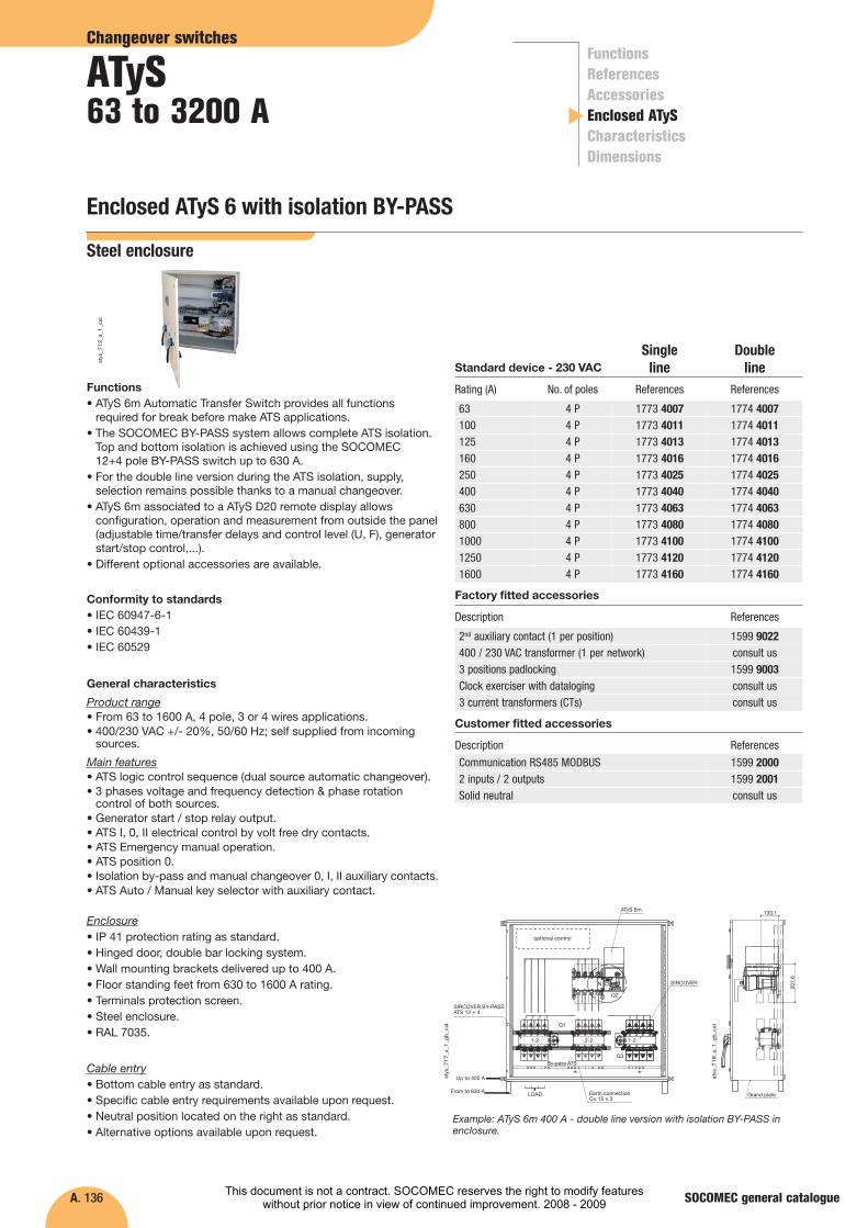
Enclosed ATyS 6 with isolation BY-PASS
SOCOMEC general catalogue
Functions• ATyS 6m Automatic Transfer Switch provides all functions
required for break before make ATS applications.• The SOCOMEC BY-PASS system allows complete ATS isolation.
Top and bottom isolation is achieved using the SOCOMEC 12+4 pole BY-PASS switch up to 630 A.
• For the double line version during the ATS isolation, supply,selection remains possible thanks to a manual changeover.
• ATyS 6m associated to a ATyS D20 remote display allowsconfiguration, operation and measurement from outside the panel(adjustable time/transfer delays and control level (U, F), generatorstart/stop control,...).
• Different optional accessories are available.
Conformity to standards• IEC 60947-6-1• IEC 60439-1• IEC 60529
General characteristics
Product range• From 63 to 1600 A, 4 pole, 3 or 4 wires applications.• 400/230 VAC +/- 20%, 50/60 Hz; self supplied from incoming
sources.
Main features• ATS logic control sequence (dual source automatic changeover).• 3 phases voltage and frequency detection & phase rotation
control of both sources.• Generator start / stop relay output.• ATS I, 0, II electrical control by volt free dry contacts.• ATS Emergency manual operation.• ATS position 0.• Isolation by-pass and manual changeover 0, I, II auxiliary contacts.• ATS Auto / Manual key selector with auxiliary contact.
Enclosure• IP 41 protection rating as standard.• Hinged door, double bar locking system.• Wall mounting brackets delivered up to 400 A.• Floor standing feet from 630 to 1600 A rating.• Terminals protection screen.• Steel enclosure.• RAL 7035.
Cable entry• Bottom cable entry as standard.• Specific cable entry requirements available upon request.• Neutral position located on the right as standard.• Alternative options available upon request.
Rating (A) References
atys
_712
_a_1
_cat
Standard device - 230 VAC
63 1774 4007
125 1774 4013160 1774 4016250 1774 4025400 1774 4040630 1774 4063800 1774 4080
1250 1774 41201600 1774 4160
No. of poles
4 P
4 P4 P4 P4 P4 P4 P
4 P4 P
100 1774 4011
References
1773 4007
1773 40131773 40161773 40251773 40401773 40631773 4080
1773 41201773 4160
1000 1774 41004 P 1773 4100
1773 40114 P
Description References
Customer fitted accessories
Communication RS485 MODBUS 1599 20002 inputs / 2 outputs 1599 2001Solid neutral consult us
Description References
Factory fitted accessories
2nd auxiliary contact (1 per position) 1599 9022400 / 230 VAC transformer (1 per network) consult us3 positions padlocking 1599 9003Clock exerciser with dataloging3 current transformers (CTs) consult us
consult us
Steel enclosure
Single line
Double line
atys
_717
_a_1
_gb_
cat
atys
_718
_a_1
_gb_
cat
SIRCOVER BY-PASSATS 12 + 4
Up to 400 A
From to 630 A LOAD Earth connectionCu 15 x 3
SIRCOVER
ATyS 6m
optional control
1-2 2-2 1-2
By-pass ATSQ3
Q1
Q2
N
133.1
207.
6
Grand plate
Example: ATyS 6m 400 A - double line version with isolation BY-PASS inenclosure.
This document is not a contract. SOCOMEC reserves the right to modify featureswithout prior notice in view of continued improvement. 2008 - 2009
A. 137
Changeover switches
ATyS
SOCOMEC general catalogue
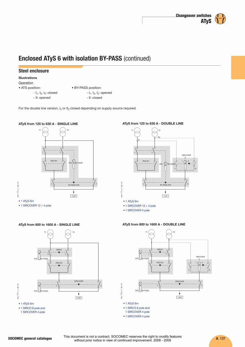
Illustrations
Operation
• ATS position:
- I1, I2, I3: closed
- II: opened
• BY-PASS position:
- I1, I2, I3: opened
- II: closed
For the double line version, I4 or II2 closed depending on supply source required.
Enclosed ATyS 6 with isolation BY-PASS (continued)
Steel enclosure
atys
_713
_a_1
_gb_
cat
T1 T2
III3
I2I1
ATyS 6m
Load
BY-PASS ATS
ATS BY-PASS
ATyS from 125 to 630 A - SINGLE LINEat
ys_7
14_a
_1_g
b_ca
t
T1 T2
S2
I4
III3
I2I1
S1
ATyS 6m
Load
BY-PASS ATS
SIRCOVER
ATS BY-PASS
III
0
II2
ATyS from 125 to 630 A - DOUBLE LINE
atys
_715
_a_1
_gb_
cat
T1 T2
III3
I2I1
ATyS 6m
Load
SIRCOVER
ATS BY-PASS
SIRCO
ATS BY-PASS
ATyS from 800 to 1600 A - SINGLE LINE
atys
_716
_a_1
_gb_
cat
T1 T2
I4
III3
I2I1
ATyS 6m
Load
SIRCOVER
SIRCOVERATS BY-PASS
III
0
II2
SIRCO
ATS BY-PASS
ATyS from 800 to 1600 A - DOUBLE LINE
• 1 ATyS 6m
• 1 SIRCOVER 12 + 4 pole• 1 ATyS 6m
• 1 SIRCOVER 12 + 4 pole
• 1 SIRCOVER 4 pole
• 1 ATyS 6m
• 1 SIRCO 8 pole and 1 SIRCOVER 4 pole
• 1 ATyS 6m
• 1 SIRCO 8 pole and 1 SIRCOVER 4 pole
• 1 SIRCOVER 4 pole
This document is not a contract. SOCOMEC reserves the right to modify featureswithout prior notice in view of continued improvement. 2008 - 2009
A. 138
�
Changeover switches
ATyS63 to 3200 A
FunctionsReferencesAccessoriesEnclosed ATySCharacteristicsDimensions
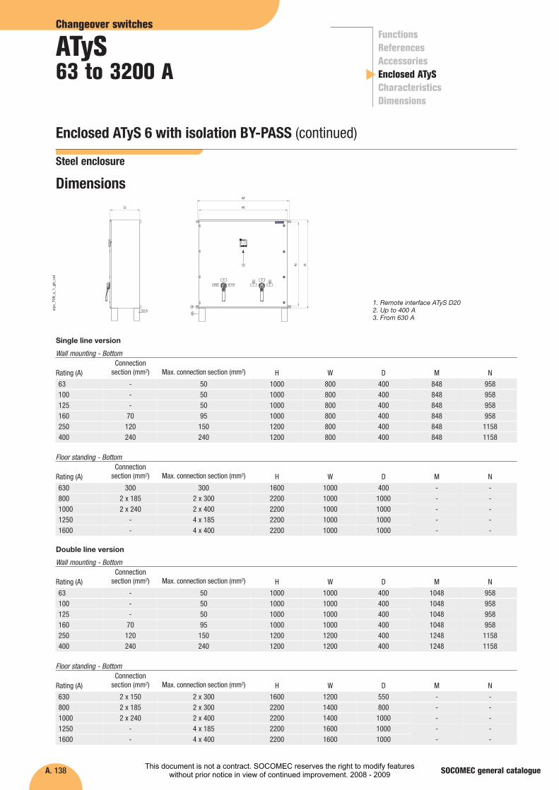
Enclosed ATyS 6 with isolation BY-PASS (continued)
SOCOMEC general catalogue
Rating (A) H W
63 1000 1000
160 1000 1000250 1200 1200400 1200 1200
D
400
400400400
Connectionsection (mm2)
-
70120240
Max. connection section (mm2)
50
95150240
Wall mounting - Bottom
1. Remote interface ATyS D202. Up to 400 A3. From 630 A
100 1000 1000 400- 50125 1000 1000 400- 50
Rating (A) H W
630 1600 1200
1250 2200 16001600 2200 1600
D
550
10001000
Connectionsection (mm2)
2 x 150
--
Max. connection section (mm2)
2 x 300
4 x 1854 x 400
Floor standing - Bottom
800 2200 1400 8002 x 185 2 x 3001000 2200 1400 10002 x 240 2 x 400
W
H
D
1
212.5
3
M
N
Dimensions
atys
_708
_a_1
_gb_
cat
Double line version
Rating (A) H W
63 1000 800
160 1000 800250 1200 800400 1200 800
D
400
400400400
Connectionsection (mm2)
-
70120240
Max. connection section (mm2)
50
95150240
Wall mounting - Bottom
100 1000 800 400- 50125 1000 800 400
M
848
848848848
848848
N
958
95811581158
958958- 50
Rating (A) H W
630 1600 1000
1250 2200 10001600 2200 1000
D
400
10001000
Connectionsection (mm2)
300
--
Max. connection section (mm2)
300
4 x 1854 x 400
Floor standing - Bottom
800 2200 1000 10002 x 185 2 x 3001000 2200 1000 10002 x 240 2 x 400
Single line version
Steel enclosure
M
-
--
N
-
--
- -- -
M
1048
104812481248
N
958
95811581158
1048 9581048 958
M
-
--
N
-
--
- -- -
This document is not a contract. SOCOMEC reserves the right to modify featureswithout prior notice in view of continued improvement. 2008 - 2009

A. 139
Changeover switches
ATyS
SOCOMEC general catalogue
Functional diagram
Priority sourceBackup source
1: position 0 control2: position I control3: position II control4: position control inhibition inputs (0-I-II)5: auxiliary contact, closed when the switch is in position I6: auxiliary contact, closed when the switch is in position II7: auxiliary contact, closed when the switch is in position 08: auxiliary contact, closed when the switch is on “AUT” mode9: auxiliary contact, closed when the switch is padlocked10: gen-set start command11: auxiliary power supply (for optional modules control)12: remote “test on-load ”input
13: DTT inhibit input. Transfer initiated as soon as the input is closed whenDTT = max. value.
14: fault output15: remote control interface16: slots for optional modules17: 3 current transformers (Cts) for ATyS metering18: by-pass position19: ATS position20: Priority source used21: Backup source used101 - 102: supply 220 -20% / 240 +20%201 - 202: supply 220 -20% / 240 +20%2
1
2
1
2
1
73210
209208
207206
205204
203202
20174
Pow
er 2
30 V
AC
2Pow
er 230 VAC
13
5 6 7 8 9
1211
10
43
21
14
1
15
13 14 24 34 43 44 53 54
101
102
103
104
105
106
313
314
315
316
317
6364
RJ
L1L2
L3N L1
L2L3
N
16
13 14 24 34 43 44 53 54
313
314
315
316
317
6364
RJ
73210
209208
20774
12
Load
ATyS6m
17
Voltage sensing
Volta
ge s
ensi
ng
21
35
46
87
911
1012
18
19
20
21
Manual changeover(only for the double line)A
IsolationBY-PASS
B+C SIRCOVER 12+4p (from 63A to 630A)
B SIRCOVER 8p (from 800A to 1600A)
C SIRCOVER 4p (from 800A to 1600A)
C C
A
B
A
B
atys
_719
_b_1
_gb_
cat
Environment
- operating temperature: -10 to +40 °C without de-rating,
- operating temperature: +40 to +65 °C with de-rating,
- maximum storage is one year,
- 80 % humidity non condensing at +55 °C,
- 95 % humidity non condensing at +40 °C,
- maximum operating altitude without switch de-rating is 2000 mabove sea level.
The complete enclosure meets the following environmental requirements:
Enclosed ATyS 6 with isolation BY-PASS (continued)
Steel enclosure
This document is not a contract. SOCOMEC reserves the right to modify featureswithout prior notice in view of continued improvement. 2008 - 2009

A. 140
ATyS M - Characteristics (according to IEC 60947)
80 A 100 A 125 A
Rated operational currents Ie (A)
Rated voltageAccording to IEC 60947-3
Load duty category A/B(1) A/B(1) A/B(1)
415 VAC AC-21 A / AC-21 B
(1) A/B: Category with index A = frequent operation / Category with index B = infrequent operation.(2) With terminal shrouds or phase barrier.(3) For a rated operating voltage Ue = 400 VAC.(4) Between the order given and the arrival in position (under the nominal conditions).
Thermal current Ith (40°C)
Rated insulation voltage Ui (V) (power circuit)Rated impulse withstand voltage Uimp (kV) (power circuit)
Overload capacityRated short-time withstand current 1 s. Icw (kA rms) Short-circuit making capacity (kA peak)(3)
ConnectionMinimum Cu cable section (mm2) Maximum Cu cable section (mm2) Tightening torque min / max (Nm)
Switching time (nominal voltage)I - 0 or II - 0 (ms)(4)
I - II or II - I (ms)(4)
Power-supply toleranceSupply 230 VAC min / max (VAC)
Control supply power demandMax current under 230 VAC (A)
Mechanical characteristicsEndurance (number of operating cycles)Weight switch (kg)
80/80 100/100 125/125
A/B(1)
160/160AC-22 A / AC-22 B 80/80 100/100 125/125 160/160AC-23 A / AC-23 B 80/80 100/100 125/125 125/160
A/B(1)
63/6363/6363/63
800 800 8006 6 6
63 A8006
160 A8006
Rated insulation voltage Ui (V) (operation circuit)Rated impulse withstand voltage Uimp (kV) (operation circuit)
300 300 3004 4 4
3004
3004
4 4 417 17 17
417
417
Prospective short-circuit current (kA rms)(3) 50 50 5050 50Associated fuse rated (A)(3) 80 100 12563 160
6 6 6 670 70 70 704/6 4/6 4/6 4/6
6704/6
50 50 50 50180 180 180 180
50180
Duration of “electrical blackout” I - II (ms) minimum (ATyS M 3s)Duration of “electrical blackout” I - II (ms) minimum (ATyS M 6s or 6e)
60 60 60 6090 90 90 90
6090
176/288 176/288 176/288 176/288 176/288
30 30 30 30 30Nominal power (VA) 6 6 6 6 6
10 000 10 000 10 000 10 0003.5 3.5 3.5 3.5
10 0003.5
690 VAC(2) AC-21 A / AC-21 B 80/80 100/100 125/125 160/160AC-22 A / AC-22 B 80/80 80/80 100/125 100/125AC-23 A / AC-23 B 63/63 80/80 80/80 80/80
63/6363/6363/63
415 VAC AC-31 A / AC-31 B 80/80 100/100 100/125 100/160AC-32 A / AC-32 B 80/80 100/100 100/125 100/160AC-33 A / AC-33 B -/80 -/80 -/80 -/80
63/6363/63-/63
According to IEC 60947-6-1
�
Changeover switches
ATyS63 to 3200 A
FunctionsReferencesAccessoriesEnclosed ATySCharacteristicsDimensions
SOCOMEC general catalogue This document is not a contract. SOCOMEC reserves the right to modify featureswithout prior notice in view of continued improvement. 2008 - 2009
A. 141
Changeover switches
ATyS
SOCOMEC general catalogue
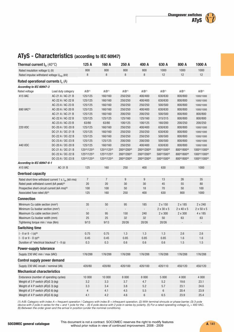
ATyS - Characteristics (according to IEC 60947)
400 A 630 A 800 A
Rated operational currents Ie (A)
Rated voltageAccording to IEC 60947-3
Load duty category A/B(1) A/B(1) A/B(1)
(1) A/B: Category with index A = frequent operation / Category with index B = infrequent operation. (2) With terminal shrouds or phase barrier. (3) 3-poledevice with 2 pole in series for the + and 1 pole for the -. (4) 4-pole device with 2 pole in series by polarity. (5) For a rated operating voltage Ue = 400 VAC.(6) Between the order given and the arrival in position (under the nominal conditions).
Thermal current Ith (40°C)
Rated insulation voltage Ui (V) Rated impulse withstand voltage Uimp (kV)
Overload capacityRated short-time withstand current 1 s. Icw (kA rms) Rated peak withstand curent (kA peak)(5)
ConnectionMinimum Cu cable section (mm2)
Maximum Cu cable section (mm2) Maximum Cu busbar width (mm)
Switching timeI - II or II - I (s)(6)
I - O or II - O (s)(6)
Power-supply toleranceSupply 230 VAC min / max (VAC)
Control supply power demandSupply 230 VAC inrush / nominal (VA)
Mechanical characteristicsEndurance (number of operating cycles)Weight of 3 P switch (ATyS 3) (kg) Weight of 4 P switch (ATyS 3) (kg)
A/B(1)A/B(1)
800 1000 10008 12 12
250 A8008
160 A8008
125 A8008
1000 A100012
9 13 2630 45 55
930
3580
Prospective short-circuit current (kA rms)(5) 18 70 5050 100Associated fuse rated (A)(5) 400 630 800250
720100160
720100125 1000
95 185 2 x 150 2 x 185
150 240 2 x 300 2 x 30032 32 50 63
50
9525
35
5025
2 x 240
4 x 185Minimum Cu busbar section (mm2) - - 2 x 30 x 5 2 x 40 x 5-- 2 x 50 x 5
63Tightening torque min / max (Nm) 20/26 20/26 20/26 -9/139/13 -
1.3 1.3 1.3 2.60.85 0.85 0.85 1.6
0.750.45
0.750.45
2.61.6
176/288176/288176/288 176/288 176/288 176/288 176/288
420/100420/80420/80 420/100 420/110 450/120 450/120
8 000 8 000 5 000 4 0003.73.8
4.75.2
5.25.7
19.623.1
10 0003.33.4
10 0003.23.3
4 00023.124.6
A/B(1)A/B(1)
415 VAC AC-31 B 400 630 800 1000250160125
According to IEC 60947-6-1
Weight of 3 P switch (ATyS 6) (kg) 4.5 5.5 6 20.44.14 23.9Weight of 4 P switch (ATyS 6) (kg) 4.6 6 6.5 23.94.24.1 25.4
Duration of “electrical blackout” I - II (s) 0.6 0.6 0.6 1.50.30.3 1.5
125/125 160/160 250/250 400/400125/125 160/160 250/250 400/400125/125 160/160 250/250 250/250125/125 160/160 250/250 400/400125/125 160/160 200/250 200/250125/125 125/125 125/160 125/16063/80 63/80 100/125 100/125
125/125 160/160 250/250 400/400125/125 160/160 250/250 250/250125/125 160/160 250/250 250/250125/125 125/125 200/200 200/200125/125 160/160 250/250 400/400
125(3)/125(3) 125(3)/125(3) 200(3)/200(3) 200(3)/200(3)
125(3)/125(3) 125(3)/125(3) 200(3)/200(3) 200(3)/200(3)
125(4)/125(4) 125(4)/125(4) 200(4)/200(4) 200(4)/200(4)
415 VAC AC-21 A / AC-21 BAC-22 A / AC-22 BAC-23 A / AC-23 B
690 VAC(2) AC-20 A / AC-20 BAC-21 A / AC-21 BAC-22 A / AC-22 BAC-23 A / AC-23 B
220 VDC DC-20 A / DC-20 BDC-21 A / DC-21 BDC-22 A / DC-22 BDC-23 A / DC-23 B
440 VDC DC-20 A / DC-20 BDC-21 A / DC-21 BDC-22 A / DC-22 BDC-23 A / DC-23 B
800/800 1000/1000
800/800 1000/1000
800/800 1000/1000
800/800 1000/1000
800/800 800/800800/800 800/800200/250 200/250800/800 1000/1000
800/800 1000/1000
800/800 1000/1000
800/800 1000/1000
800/800 1000/1000
800(4)/800(4) 1000(4)/1000(4)
800(4)/800(4) 1000(4)/1000(4)
800(4)/800(4) 1000(4)/1000(4)
630/630630/630500/500630/630500/500315/315160/200630/630630/630500/500500/500630/630
500(3)/500(3)
500(3)/500(3)
500(4)/500(4)
This document is not a contract. SOCOMEC reserves the right to modify featureswithout prior notice in view of continued improvement. 2008 - 2009

A. 142
��
Changeover switches
ATyS63 to 3200 A
FunctionsReferencesAccessoriesEnclosed ATySCharacteristicsDimensions
SOCOMEC general catalogue
ATyS - Characteristics (according to IEC 60947)
1800 A 2000 A 2500 A
Rated operational currents Ie (A)
Rated voltageAccording to IEC 60947-3
Load duty category A/B(1) A/B(1) A/B(1)
(1) A/B: Category with index A = frequent operation / Category with index B = infrequent operation. (2) With terminal shrouds or phase barrier. (3) 4-pole device with 2 pole in series by polarity. (4) For a rated operating voltage Ue = 400 VAC. (5) Between the order given and the arrival in position (underthe nominal conditions). (6) Weight for ATyS 3e, 6e and 6m.
Thermal current Ith (40°C) Rated insulation voltage Ui (V) Rated impulse withstand voltage Uimp (kV)
Overload capacityRated short-time withstand current 1 s. Icw (kA rms) Rated peak withstand curent (kA peak)(4)
Connection
Maximum Cu cable section (mm2) Maximum Cu busbar width (mm)
Switching timeI - II or II - I (s)(5)
I - O or II - O (s)(5)
Power-supply toleranceSupply 230 VAC min / max (VAC)
Control supply power demandSupply 230 VAC inrush / nominal (VA)
Mechanical characteristicsEndurance (number of operating cycles)Weight of 3 P switch (ATyS 3) (kg) Weight of 4 P switch (ATyS 3) (kg)
A/B(1)A/B(1)
1000 1000 100012 12 12
1600 A100012
1250 A100012
3200 A100012
50 55 55110 120 120
50110
55120
Prospective short-circuit current (kA rms)(4) 100 - -100 -Associated fuse rated (A)(4) 1800 - -1600
3580100
1250 -
6 x 185 6 x 185 - -100 100 100 100
4 x 18563
Minimum Cu busbar section (mm2) 2 x 80 x 5 3 x 100 x 5 2 x 100 x 10 2 x 100 x 102 x 60 x 5 2 x 100 x 10-
100Tightening torque min / max (Nm) 40/45 40/45 40/45 40/4520/26 40/45
2.6 2.6 2 21.6 1.6 1 1
2.61.6
21
176/288176/288 176/288 176/288 176/288 176/288
450/120450/120 450/120 550/390 550/390 550/390
3 000 3 000 3 000 3 00036.142.1
36.142.1
47(6)
57(6)
51(6)
61(6)
4 00024.629.6
3 00059(6)
69(6)
A/B(1)
415 VAC AC-31 B 1800 2000 2500 -16001250
According to IEC 60947-6-1
Weight of 3 P switch (ATyS 6) (kg) 36.9 - 47(6) 51(6)25.4 59(6)
Weight of 4 P switch (ATyS 6) (kg) 42.9 - 57(6) 61(6)30.4 69(6)
Duration of “electrical blackout” I - II (s) 1.6 1.6 1 11.5 1
415 VAC AC-21 A / AC-21 BAC-22 A / AC-22 BAC-23 A / AC-23 B
690 VAC(2) AC-20 A / AC-20 BAC-21 A / AC-21 BAC-22 A / AC-22 BAC-23 A / AC-23 B
220 VDC DC-20 A / DC-20 BDC-21 A / DC-21 BDC-22 A / DC-22 BDC-23 A / DC-23 B
440 VDC DC-20 A / DC-20 BDC-21 A / DC-21 BDC-22 A / DC-22 BDC-23 A / DC-23 B
-/2500 -/3200-/2500 -/3200-/1600 -/1600
-/- -/--/- -/--/- -/--/- -/--/- -/--/- -/--/- -/--/- -/--/- -/--/- -/--/- -/--/- -/-
-/2000-/2000-/1600
-/--/--/--/--/--/--/--/--/--/--/--/-
1250/1250 1600/1600 1800/18001250/1250 1600/1600 1800/18001250/1250 1250/1250 1250/12501250/1250 1600/1600 1800/1800800/800 1000/1000 1000/1000800/800 1000/1000 1000/1000200/250 500/500 500/500
1250/1250 1600/1600 1800/18001250/1250 1250/1250 1250/12501250/1250 1250/1250 1250/12501250/1250 1250/1250 1250/12501250/1250 1600/1600 1800/1800
1250(3)/1250(3) 1250(3)/1250(3) 1250(3)/1250(3)
1250(3)/1250(3) 1250(3)/1250(3) 1250(3)/1250(3)
1250(3)/1250(3) 1250(3)/1250(3) 1250(3)/1250(3)
This document is not a contract. SOCOMEC reserves the right to modify featureswithout prior notice in view of continued improvement. 2008 - 2009
A. 143
Changeover switches
ATyS
SOCOMEC general catalogue
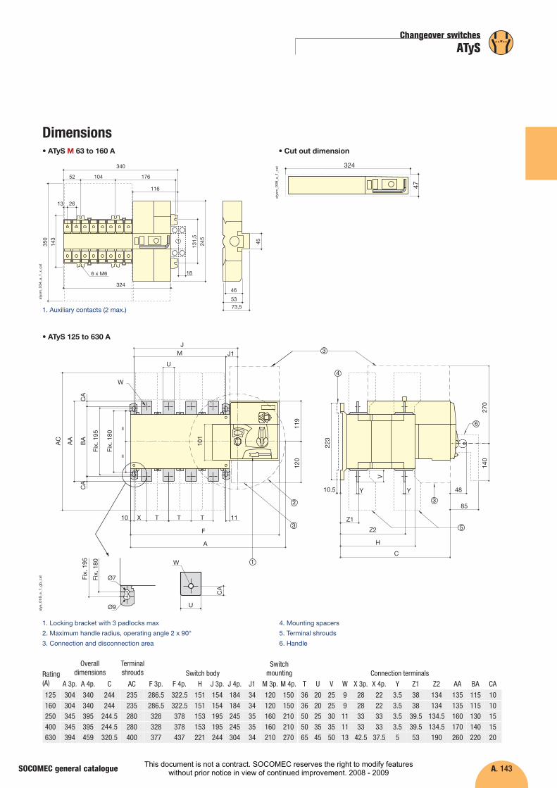
Dimensions• ATyS M 63 to 160 A • Cut out dimension
1
340
17610452
324
116
245
131,
5
45143
350
2613
73,553
46
186 x M6
atys
m_0
34_a
_1_x
_cat
324
47
atys
m_0
08_a
_1_c
at
10
W
U
MJ
J1
X T T T 11
C
H
Z2
Z1
10.5 Y Y
85
48
F
A
120
140
270
V
223
119
=
Fix.
180
Fix.
195
BA
CA
CA
AA
AC
101
=
Ø7
Ø9
Fix.
180
Fix.
195 1
32
3
3
4
5
6
CA
W
U
atys
_018
_e_1
_gb_
cat
1. Locking bracket with 3 padlocks max
2. Maximum handle radius, operating angle 2 x 90°
3. Connection and disconnection area
4. Mounting spacers
5. Terminal shrouds
6. Handle
1. Auxiliary contacts (2 max.)
C
244244
244.5244.5320.5
Rating(A)
Overall dimensions
Terminalshrouds Switch body
Switchmounting Connection terminals
A 3p. A 4p. AC F 3p. F 4p. H J 3p. J 4p. J1 M 3p. M 4p. T U V W X 3p. X 4p. Y Z1 Z2 AA BA CA
125 304 340 235 286.5 322.5 151 154 184 34 120 150 36 20 25 9 28 22 3.5 38 134 135 115 10160 304 340 235 286.5 322.5 151 154 184 34 120 150 36 20 25 9 28 22 3.5 38 134 135 115 10250 345 395 280 328 378 153 195 245 35 160 210 50 25 30 11 33 33 3.5 39.5 134.5 160 130 15400 345 395 280 328 378 153 195 245 35 160 210 50 35 35 11 33 33 3.5 39.5 134.5 170 140 15630 394 459 400 377 437 221 244 304 34 210 270 65 45 50 13 42.5 37.5 5 53 190 260 220 20
• ATyS 125 to 630 A
This document is not a contract. SOCOMEC reserves the right to modify featureswithout prior notice in view of continued improvement. 2008 - 2009
A. 144
�
Changeover switches
ATyS63 to 3200 A
FunctionsReferencesAccessoriesEnclosed ATySCharacteristicsDimensions
SOCOMEC general catalogue
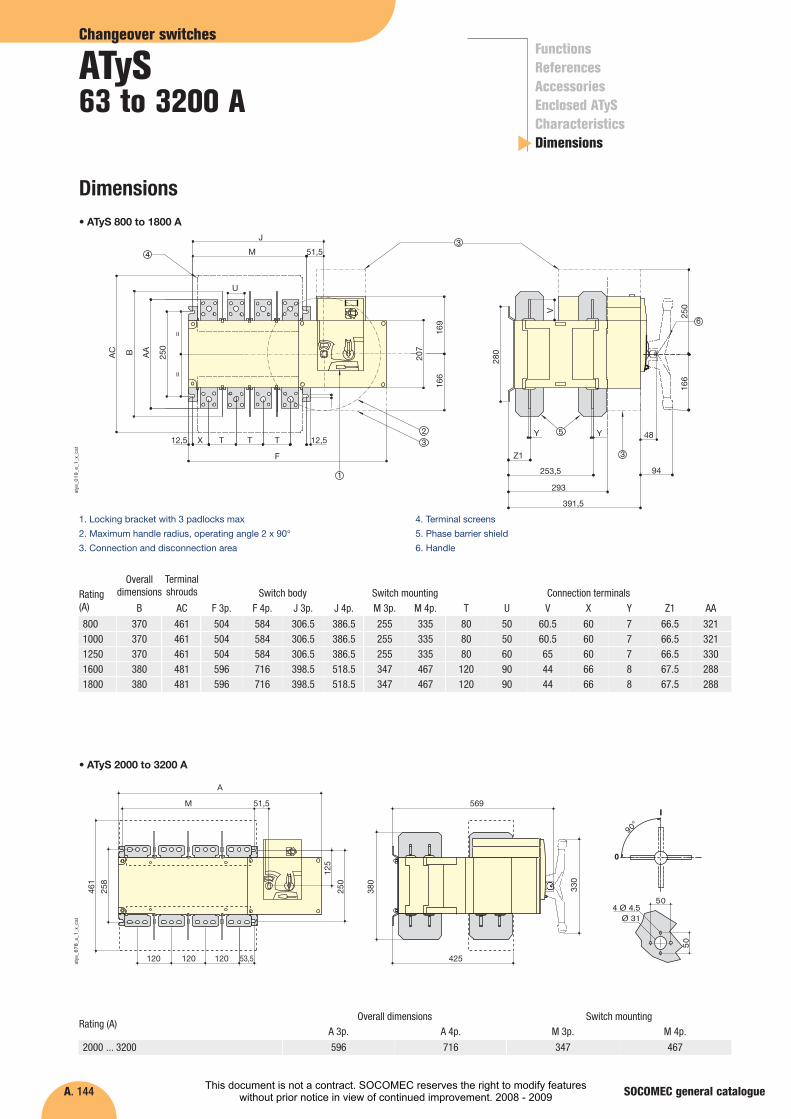
Dimensions
M 51,5
53,5120120120
A
250
258
461
569
425
380
125
330
0
I
90°
504 Ø 4.5
Ø 31
50
atys
_678
_a_1
_x_c
at
Rating (A) Overall dimensions Switch mounting
A 3p. M 3p. M 4p.
2000 ... 3200 596
A 4p.
716 347 467
• ATyS 2000 to 3200 A
F
12,5
=
207
169
166
280
250
166
V
=
250
AA
12,5
391,5
293
253,5
Z1
Y Y 48
94
X
M 51,5
J
T T T
1
3
BAC
23
34
5
6
U
atys
_019
_e_1
_x_c
at
1. Locking bracket with 3 padlocks max
2. Maximum handle radius, operating angle 2 x 90°
3. Connection and disconnection area
4. Terminal screens
5. Phase barrier shield
6. Handle
Rating(A)
Overalldimensions
Terminalshrouds Switch body Switch mounting Connection terminals
B AC F 3p. F 4p. J 3p. J 4p. M 3p. M 4p. T U V X Y Z1 AA
800 370 461 504 584 306.5 386.5 255 335 80 50 60.5 60 7 66.5 3211000 370 461 504 584 306.5 386.5 255 335 80 50 60.5 60 7 66.5 3211250 370 461 504 584 306.5 386.5 255 335 80 60 65 60 7 66.5 33016001800
380380
481481
596596
716716
398.5398.5
518.5518.5
347347
467467
120120
9090
4444
6666
88
67.567.5
288288
• ATyS 800 to 1800 A
This document is not a contract. SOCOMEC reserves the right to modify featureswithout prior notice in view of continued improvement. 2008 - 2009
A. 145
Changeover switches
ATyS
SOCOMEC general catalogue
Dimensions
33 8.58.5
50
3310
ø 9
ø 15
svr_
077_
a_1_
x_ca
t
16 x 11
60
28.5 15.7515.75
28.5
15
svr_
078_
b_1_
x_ca
t
15
5 5
12,5
25 253030
454590
ø12,5
svr_
098_
a_1_
x_ca
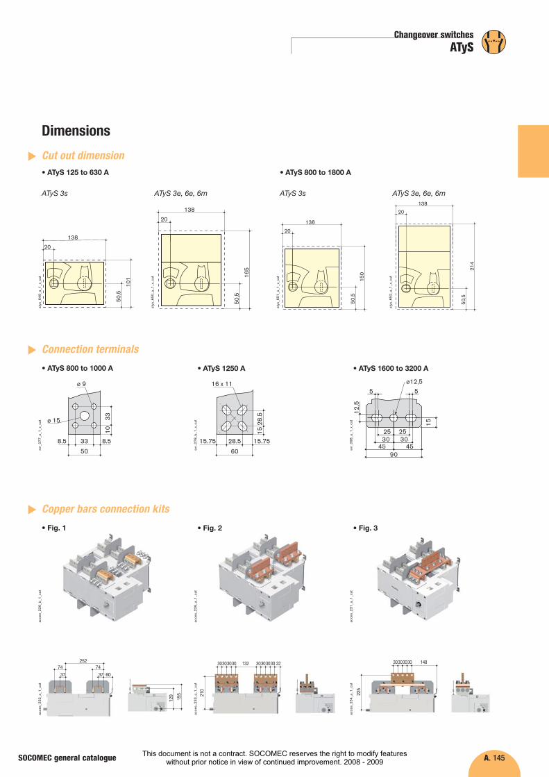
tConnection terminals
�
Cut out dimension
�
• ATyS 800 to 1000 A • ATyS 1250 A • ATyS 1600 to 3200 A
25274
37
74
37 60
129
155
30303030 132 30303030 22
210
30303030 148
225
acce
s_22
6_b_
1_ca
tac
ces_
232_
a_1_
cat
acce
s_23
3_a_
1_ca
t
acce
s_23
4_a_
1_ca
t
acce
s_22
9_a_
1_ca
t
acce
s_23
1_a_
1_ca
t
Copper bars connection kits�
• Fig. 1 • Fig. 2 • Fig. 3
atys
_649
_a_1
_x_c
at
atys
_650
_a_1
_x_c
at
50,5
20
138
101
50,5
20
138
165
ATyS 3s ATyS 3e, 6e, 6m
atys
_651
_a_1
_x_c
at
atys
_652
_a_1
_x_c
at
50,5
20
138
150
50,5
20
138
214
ATyS 3s ATyS 3e, 6e, 6m
• ATyS 125 to 630 A • ATyS 800 to 1800 A
This document is not a contract. SOCOMEC reserves the right to modify featureswithout prior notice in view of continued improvement. 2008 - 2009