Embed Size (px)
Citation preview
Ch. 5 – Frame Relay
CCNA 4 version 3.0
Rick Graziani
Cabrillo College

Rick Graziani [email protected] 2
Note
• Much of the information in this presentation comes from the CCNP 2 version 3.0 module on Frame Relay.
• I find a lot of the information in CCNA 4 module 5 Frame Relay not very well written or not well explained.
• CCNP 3 does a much better job of presenting and explaining these concepts.

Rick Graziani [email protected] 3
Overview
• Identify the components of a Frame Relay network
• Explain the scope and purpose of Frame Relay
• Discuss the technology of Frame Relay
• Compare point-to-point and point-to-multipoint topologies
• Examine the topology of a Frame Relay network
• Configure a Frame Relay Permanent Virtual Circuit (PVC)
• Create a Frame Relay Map on a remote network
• Explain the issues of a non-broadcast multi-access network
• Describe the need for subinterfaces and how to configure them
• Verify and troubleshoot a Frame Relay connection

Rick Graziani [email protected] 4
Introducing Frame Relay
• Frame Relay is a packet-switched, connection-oriented, WAN service. It operates at the data link layer of the OSI reference model.
• Frame Relay uses a subset of the high-level data link control (HDLC) protocol called Link Access Procedure for Frame Relay (LAPF).
• Frames carry data between user devices called data terminal equipment (DTE), and the data communications equipment (DCE) at the edge of the WAN.– It does not define the way the data is transmitted within the service
provider’s Frame Relay cloud.– This is ATM in many cases!

Rick Graziani [email protected] 5
Frame Relay vs. X.25
• Frame Relay does not have the sequencing, windowing, and retransmission mechanisms that are used by X.25.
• Without the overhead, the streamlined operation of Frame Relay outperforms X.25.
• Typical speeds range from 56 kbps up to 2 Mbps, although higher speeds are possible. (Up to 45 Mbps)
• The network providing the Frame Relay service can be either a carrier-provided public network or a privately owned network.
• Because it was designed to operate on high-quality digital lines, Frame Relay provides no error recovery mechanism.
• If there is an error in a frame it is discarded without notification.

Rick Graziani [email protected] 6
Introducing Frame Relay
• A Frame Relay network may be privately owned, but it is more commonly provided as a service by a public carrier.
• It typically consists of many geographically scattered Frame Relay switches interconnected by trunk lines.
• Frame Relay is often used to interconnect LANs. When this is the case, a router on each LAN will be the DTE.
• A serial connection, such as a T1/E1 leased line, will connect the router to a Frame Relay switch of the carrier at the nearest point-of-presence for the carrier. (access circuit)
Access circuits

Rick Graziani [email protected] 7
DTE – Data Terminal Equipment
• DTEs generally are considered to be terminating equipment for a specific network and typically are located on the premises of the customer.
• The customer may also own this equipment.• Examples of DTE devices are routers and Frame Relay Access
Devices (FRADs). • A FRAD is a specialized device designed to provide a connection
between a LAN and a Frame Relay WAN.

Rick Graziani [email protected] 8
DCE – Data Communications Equipment
• DCEs are carrier-owned internetworking devices. • The purpose of DCE equipment is to provide clocking and switching
services in a network. • In most cases, these are packet switches, which are the devices that
actually transmit data through the WAN.• The connection between the customer and the service provider is
known as the User-to-Network Interface (UNI). • The Network-to-Network Interface (NNI) is used to describe how
Frame Relay networks from different providers connect to each other.
UNI NNI

Rick Graziani [email protected] 9
Frame Relay terminology
• The connection through the Frame Relay network between two DTEs is called a virtual circuit (VC).
• Switched Virtual Circuits (SVCs) are Virtual circuits may be established dynamically by sending signaling messages to the network.
• However, SVCs are not very common. • Permanent Virtual Circuits (PVCs) are more common.• PVC are VCs that have been preconfigured by the carrier are used. • The switching information for a VC is stored in the memory of the switch.
An SVC between the same two DTEs may change.
A PVC between the same two DTEs will always be the same.
Path may change. Always same Path.

Rick Graziani [email protected] 10
Access Circuits and Cost Savings
• The FRAD or router connected to the Frame Relay network may have multiple virtual circuits connecting it to various end points.
• This makes it a very cost-effective replacement for a full mesh of access lines.
• Each end point needs only a single access line and interface. • More savings arise as the capacity of the access line is based on the
average bandwidth requirement of the virtual circuits, rather than on the maximum bandwidth requirement.
• Note: Also do not have to pay for leased line between two sites even when no traffic is being sent.

Rick Graziani [email protected] 11
IETF Frame Relay Frame
• Cisco routers support two types of Frame Relay headers. – Cisco, which is a 4-byte header. – IETF, which is a 2-byte header that conforms to the IETF standards.
• The Cisco proprietary 4-byte header is the default and cannot be used if the router is connected to another vendor's equipment across a Frame Relay network.

Rick Graziani [email protected] 12
DLCI
• A data-link connection identifier (DLCI) identifies the logical VC between the CPE and the Frame Relay switch.
• The Frame Relay switch maps the DLCIs between each pair of routers to create a PVC.
• DLCIs have local significance, although there some implementations that use global DLCIs.
• DLCIs 0 to 15 and 1008 to 1023 are reserved for special purposes.• Service providers assign DLCIs in the range of 16 to 1007.
– DLCI 1019, 1020: Multicasts– DLCI 1023: Cisco LMI– DLCI 0: ANSI LMI

Rick Graziani [email protected] 13
DLCI
• Your Frame Relay provider sets up the DLCI numbers to be used by the routers for establishing PVCs.

Rick Graziani [email protected] 14
Frame Relay bandwidth and flow control
• Local access rate – This is the clock speed or port speed of the connection or local loop to the Frame Relay cloud. – It is the rate at which data travels into or out of the network,
regardless of other settings.
• Committed Information Rate (CIR) – This is the rate, in bits per second, at which the Frame Relay switch agrees to transfer data. – The rate is usually averaged over a period of time, referred to as
the committed rate measurement interval (Tc). – In general, the duration of Tc is proportional to the "burstiness" of
the traffic.
The first thing we need to do is become familiar with some of the terminology.

Rick Graziani [email protected] 15
Frame Relay bandwidth and flow control
• Oversubscription – Oversubscription is when the sum of the CIRs on all the VCs exceeds the access line speed. – Oversubscription can also occur when the access line can support
the sum of CIRs purchased, but not of the CIRs plus the bursting capacities of the VCs.
– Oversubscription increases the likelihood that packets will be dropped.
per VC

Rick Graziani [email protected] 16
Frame Relay bandwidth and flow control
• Committed burst (Bc) – The maximum number of bits that the switch agrees to transfer during any Tc. – The higher the Bc-to-CIR ratio, the longer the switch can handle a
sustained burst. – For example, if the Tc is 2 seconds and the CIR is 32 kbps, the Bc
is 64 kbps. – The Tc calculation is Tc = Bc/CIR.
• Committed Time Interval (Tc) – Tc is not a recurrent time interval. It is used strictly to measure inbound data, during which time it acts like a sliding window. Inbound data triggers the Tc interval.
Tc = 2 seconds Bc = 64 kbps CIR = 32 kbps

Rick Graziani [email protected] 17
Frame Relay bandwidth and flow control
• Excess burst (Be) – This is the maximum number of uncommitted bits that the Frame Relay switch attempts to transfer beyond the CIR.– Excessive Burst (Be) is dependent on the service offerings
available from your vendor, but it is typically limited to the port speed of the local access loop.
• Excess Information Rate (EIR) – This defines the maximum bandwidth available to the customer, which is the CIR plus the Be.– Typically, the EIR is set to the local access rate. – In the event the provider sets the EIR to be lower than the local
access rate, all frames beyond that maximum can be discarded automatically, even if there is no congestion.

Rick Graziani [email protected] 18
Frame Relay bandwidth and flow control
• Forward Explicit Congestion Notification (FECN) – When a Frame Relay switch recognizes congestion in the network, it sends an FECN packet to the destination device. – This indicates that congestion has occurred.
• Backward Explicit Congestion Notification (BECN) – When a Frame Relay switch recognizes congestion in the network, it sends a BECN packet to the source router. – This instructs the router to reduce the rate at which it is sending
packets. – With Cisco IOS Release 11.2 or later, Cisco routers can respond to
BECN notifications. – This topic is discussed later in this module.

Rick Graziani [email protected] 19
Frame Relay bandwidth and flow control
• Discard eligibility (DE) bit – When the router or switch detects network congestion, it can mark the packet "Discard Eligible". – The DE bit is set on the traffic that was received after the CIR was
met. – These packets are normally delivered. However, in periods of
congestion, the Frame Relay switch will drop packets with the DE bit set first.

Rick Graziani [email protected] 20
Frame Relay bandwidth
• Several factors determine the rate at which a customer can send data on a Frame Relay network.
• Foremost in limiting the maximum transmission rate is the capacity of the local loop to the provider.
• If the local loop is a T1, no more than 1.544 Mbps can be sent. • In Frame Relay terminology, the speed of the local loop is called the local
access rate. • Providers use the CIR parameter to provision network resources and
regulate usage. • For example, a company with a T1 connection to the packet-switched
network (PSN) may agree to a CIR of 768 Kbps. • This means that the provider guarantees 768 Kbps of bandwidth to the
customer’s link at all times.

Rick Graziani [email protected] 21
Frame Relay bandwidth
• Typically, the higher the CIR, the higher the cost of service.
• Customers can choose the CIR that is most appropriate to their bandwidth needs, as long as the CIR is less than or equal to the local access rate.
• If the CIR of the customer is less than the local access rate, the customer and provider agree on whether bursting above the CIR is allowed.
• If the local access rate is T1 or 1.544 Mbps, and the CIR is 768 Kbps, half of the potential bandwidth (as determined by the local access rate) remains available.

Rick Graziani [email protected] 22
Frame Relay bandwidth
• Many providers allow their customers to purchase a CIR of 0 (zero).
• This means that the provider does not guarantee any throughput.
• In practice, customers usually find that their provider allows them to burst over the 0 (zero) CIR virtually all of the time.
• If a CIR of 0 (zero) is purchased, carefully monitor performance in order to determine whether or not it is acceptable.
• Frame Relay allows a customer and provider to agree that under certain circumstances, the customer can “burst” over the CIR.
• Since burst traffic is in excess of the CIR, the provider does not guarantee that it will deliver the frames.

Rick Graziani [email protected] 23
Frame Relay bandwidth
• Either a router or a Frame Relay switch tags each frame that is transmitted beyond the CIR as eligible to be discarded.
• When a frame is tagged DE, a single bit in the Frame Relay frame is set to 1.
• This bit is known as the discard eligible (DE) bit.• The Frame Relay specification also includes a protocol for congestion
notification. • This mechanism relies on the FECN/ BECN bits in the Q.922 header of
the frame. • The provider’s switches or the customer’s routers can selectively set
the DE bit in frames. • These frames will be the first to be dropped when congestion occurs.

Rick Graziani [email protected] 24
LMI – Local Management Interface
• LMI is a signaling standard between the DTE and the Frame Relay switch. • LMI is responsible for managing the connection and maintaining the status between devices.• LMI includes:
– A keepalive mechanism, which verifies that data is flowing – A multicast mechanism, which provides the network server (router)
with its local DLCI.– The multicast addressing, which can give DLCIs global rather than
local significance in Frame Relay networks (not common).– A status mechanism, which provides an ongoing status on the
DLCIs known to the switch

Rick Graziani [email protected] 25
LMI
• In order to deliver the first LMI services to customers as soon as possible, vendors and standards committees worked separately to develop and deploy LMI in early Frame Relay implementations.
• The result is that there are three types of LMI, none of which is compatible with the others.
• Cisco, StrataCom, Northern Telecom, and Digital Equipment Corporation (Gang of Four) released one type of LMI, while the ANSI and the ITU-T each released their own versions.
• The LMI type must match between the provider Frame Relay switch and the customer DTE device.
LMI

Rick Graziani [email protected] 26
LMI
• In Cisco IOS releases prior to 11.2, the Frame Relay interface must be manually configured to use the correct LMI type, which is furnished by the service provider.
• If using Cisco IOS Release 11.2 or later, the router attempts to automatically detect the type of LMI used by the provider switch.
• This automatic detection process is called LMI autosensing. • No matter which LMI type is used, when LMI autosense is active, it
sends out a full status request to the provider switch.
LMI
Rick Graziani [email protected] 27
LMI
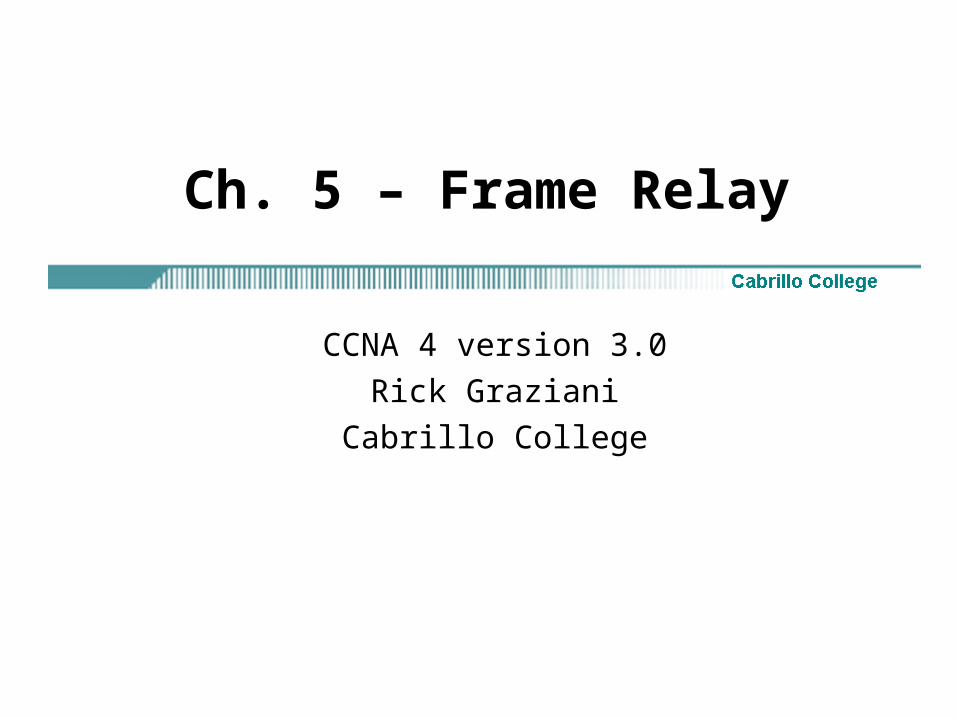
• Frame Relay devices can now listen in on both DLCI 1023 or Cisco LMI and DLCI 0 or ANSI and ITU-T simultaneously.
• The order is ansi, q933a, cisco and is done in rapid succession to accommodate intelligent switches that can handle multiple formats simultaneously.
• The Frame Relay switch uses LMI to report the status of configured PVCs.
• The three possible PVC states are as follows:– Active state – Indicates that the connection is active and that
routers can exchange data. – Inactive state – Indicates that the local connection to the Frame
Relay switch is working, but the remote router connection to the Frame Relay switch is not working.
– Deleted state – Indicates that no LMI is being received from the Frame Relay switch, or that there is no service between the CPE router and Frame Relay switch.

Rick Graziani [email protected] 28
DLCI Mapping to Network Address
• Manual– Manual: Administrators use a frame relay map statement.
• Dynamic – Inverse Address Resolution Protocol (I-ARP) provides a given
DLCI and requests next-hop protocol addresses for a specific connection.
– The router then updates its mapping table and uses the information in the table to forward packets on the correct route.

Rick Graziani [email protected] 29
Inverse ARP
• Once the router learns from the switch about available PVCs and their corresponding DLCIs, the router can send an Inverse ARP request to the other end of the PVC. (unless statically mapped – later)
• For each supported and configured protocol on the interface, the router sends an Inverse ARP request for each DLCI. (unless statically mapped)
• In effect, the Inverse ARP request asks the remote station for its Layer 3 address.
• At the same time, it provides the remote system with the Layer 3 address of the local system.
• The return information from the Inverse ARP is then used to build the Frame Relay map.
12

Rick Graziani [email protected] 30
Inverse ARP
• Inverse Address Resolution Protocol (Inverse ARP) was developed to provide a mechanism for dynamic DLCI to Layer 3 address maps.
• Inverse ARP works much the same way Address Resolution Protocol (ARP) works on a LAN.
• However, with ARP, the device knows the Layer 3 IP address and needs to know the remote data link MAC address.
• With Inverse ARP, the router knows the Layer 2 address which is the DLCI, but needs to know the remote Layer 3 IP address.

Rick Graziani [email protected] 31
• cisco - Default.
– Use this if connecting to another Cisco router.
• Ietf - Select this if connecting to a non-Cisco router.
– RFC 1490
Router(config-if)#encapsulation frame-relay {cisco | ietf}
Frame Relay Encapsulation

Rick Graziani [email protected] 32
Frame Relay LMI
• It is important to remember that the Frame Relay service provider maps the virtual circuit within the Frame Relay network connecting the two remote customer premises equipment (CPE) devices that are typically routers.
• Once the CPE device, or router, and the Frame Relay switch are exchanging LMI information, the Frame Relay network has everything it needs to create the virtual circuit with the other remote router.
• The Frame Relay network is not like the Internet where any two devices connected to the Internet can communicate.
• In a Frame Relay network, before two routers can exchange information, a virtual circuit between them must be set up ahead of time by the Frame Relay service provider.
Router(config-if)#frame-relay lmi-type {ansi | cisco | q933a}

Rick Graziani [email protected] 33
HubCity(config)# interface serial 0
HubCity(config-if)# ip address 172.16.1.2 255.255.255.0
HubCity(config-if)# encapsulation frame-relay
Spokane(config)# interface serial 0
Spokane(config-if)# ip address 172.16.1.1 255.255.255.0
Spokane(config-if)# encapsulation frame-relay
Frame RelayNetw ork
HeadquartersHub City
Satellite Office 1Spokane
172.16.1.1172.16.1.2
DLCI 101 DLCI 102
Minimum Frame Relay Configuration

Rick Graziani [email protected] 34
• Cisco Router is now ready to act as a Frame-Relay DTE device.
The following process occurs:1. The interface is enabled.2. The Frame-Relay switch announces the configured DLCI(s) to the
router.3. Inverse ARP is performed to map remote network layer addresses to
the local DLCI(s).
The routers can now ping each other!
Minimum Frame Relay Configuration
Frame RelayNetw ork
HeadquartersHub City
Satellite Office 1Spokane
172.16.1.1172.16.1.2
DLCI 101 DLCI 102

Rick Graziani [email protected] 35
HubCity# show frame-relay map
Serial0 (up): ip 172.16.1.1 dlci 101, dynamic, broadcast, status defined, active
Frame RelayNetw ork
HeadquartersHub City
Satellite Office 1Spokane
172.16.1.1172.16.1.2
DLCI 101 DLCI 102
Inverse ARP
• dynamic refers to the router learning the IP address via Inverse ARP
• The DLCI 101 is configured on the Frame Relay Switch by the provider.
• We will see this in a moment.

Rick Graziani [email protected] 36
Inverse ARP Limitations
• Inverse ARP only resolves network addresses of remote Frame-Relay connections that are directly connected.
• Inverse ARP does not work with Hub-and-Spoke connections. (We will see this in a moment.)
• When using dynamic address mapping, Inverse ARP requests a next-hop protocol address for each active PVC.
• Once the requesting router receives an Inverse ARP response, it updates its DLCI-to-Layer 3 address mapping table.
• Dynamic address mapping is enabled by default for all protocols enabled on a physical interface.
• If the Frame Relay environment supports LMI autosensing and Inverse ARP, dynamic address mapping takes place automatically.
• Therefore, no static address mapping is required.
Frame RelayNetw ork
HeadquartersHub City
Satellite Office 1Spokane
172.16.1.1172.16.1.2
DLCI 101 DLCI 102

Rick Graziani [email protected] 37
Configuring Frame Relay maps
• If the environment does not support LMI autosensing and Inverse ARP, a Frame Relay map must be manually configured.
• Use the frame-relay map command to configure static address mapping.
• Once a static map for a given DLCI is configured, Inverse ARP is disabled on that DLCI.
• The broadcast keyword is commonly used with the frame-relay map command.
• The broadcast keyword provides two functions. – Forwards broadcasts when multicasting is not enabled.– Simplifies the configuration of OSPF for nonbroadcast networks
that use Frame Relay. (coming)
Router(config-if)#frame-relay map protocol protocol-address dlci [broadcast] [ietf | cisco]

Rick Graziani [email protected] 38
Frame Relay Maps
Remote IP Address
Local DLCIUses cisco encapsulation for this DLCI (not needed, default)
By default, cisco is the default encapsulation

Rick Graziani [email protected] 39
More on Frame Relay Encapsulation
• If the Cisco encapsulation is configured on a serial interface, then by default, that encapsulation applies to all VCs on that serial interface.
• If the equipment at the destination is Cisco and non-Cisco, configure the Cisco encapsulation on the interface and selectively configure IETF encapsulation per DLCI, or vice versa.
• These commands configure the Cisco Frame Relay encapsulation for all PVCs on the serial interface.
• Except for the PVC corresponding to DLCI 49, which is explicitly configured to use the IETF encapsulation.
Applies to all DLCIs unless configured otherwise

Rick Graziani [email protected] 40
Verifying Frame Relay interface configuration
• The show interfaces serial command displays information regarding the encapsulation and the status of Layer 1 and Layer 2.
• It also displays information about the multicast DLCI, the DLCIs used on the Frame Relay-configured serial interface, and the DLCI used for the LMI signaling.

Rick Graziani [email protected] 41
show interfaces serial
• To simplify the WAN management, use the description command at the interface level to record the circuit number.
Atlanta(config)#interface serial 0/0
Atlanta(config-if)#description Circuit-05QHDQ101545-080TCOM-002
Atlanta(config-if)#^z
Atlanta#show interfaces serial 0/0
Serial 0/0 is up, line protocol is up Hardware is MCI Serial
Description Circuit-05QHDQ101545-080TCOM-002
Internet address is 150.136.190.203, subnet mask 255.255.255.0
MTU 1500 bytes, BW 1544 Kbit, DLY 20000 uses, rely 255/255, load 1/255

Rick Graziani [email protected] 42
show frame-relay pvc
• The command show frame-relay pvc shows the status of all PVCs configured on the router.
• This command is also useful for viewing the number of Backward Explicit Congestion Notification (BECN) and Forward Explicit Congestion Notification (FECN) packets received by the router.
• If a single PVC is specified, only the status of that PVC is shown.
Rick Graziani [email protected] 43
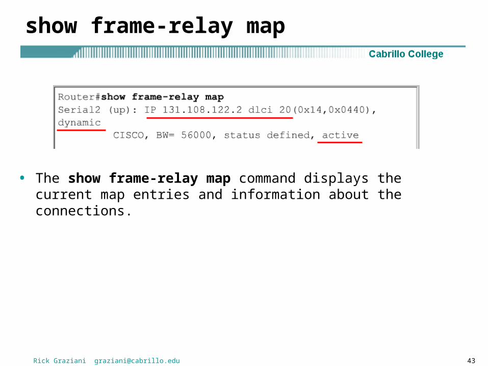
show frame-relay map
• The show frame-relay map command displays the current map entries and information about the connections.

Rick Graziani [email protected] 44
show frame-relay lmi
• The show frame-relay lmi command displays LMI traffic statistics showing the number of status messages exchanged between the local router and the Frame Relay switch.

Rick Graziani [email protected] 45
clear frame-relay-inarp
• To clear dynamically created Frame Relay maps, which are created using Inverse ARP, use the clear frame-relay-inarp command.
Rick Graziani [email protected] 46
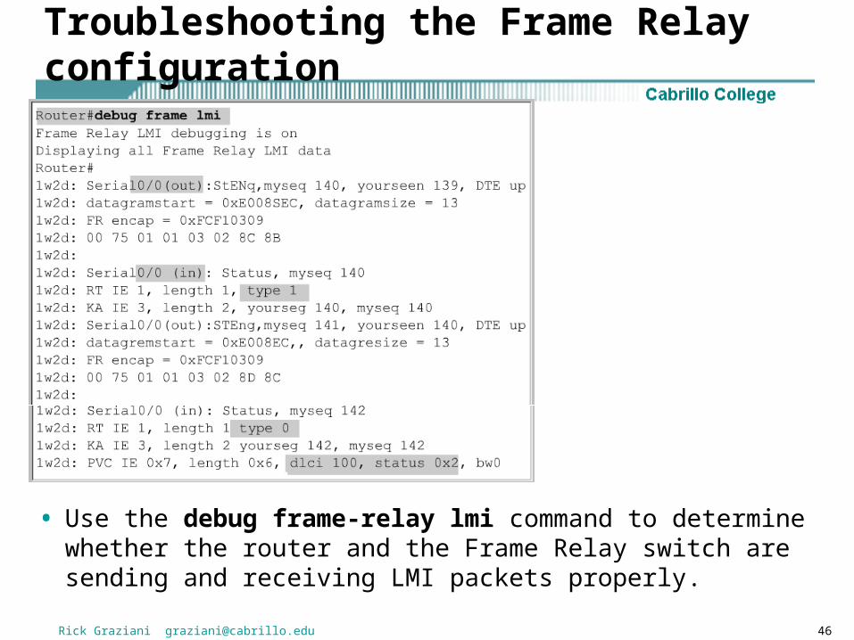
Troubleshooting the Frame Relay configuration
• Use the debug frame-relay lmi command to determine whether the router and the Frame Relay switch are sending and receiving LMI packets properly.

Rick Graziani [email protected] 47
debug frame-relay lmi (continued)
• The possible values of the status field are as follows:
• 0x0 – Added/inactive means that the switch has this DLCI programmed but for some reason it is not usable. The reason could possibly be the other end of the PVC is down.
• 0x2 – Added/active means the Frame Relay switch has the DLCI and everything is operational.
• 0x4 – Deleted means that the Frame Relay switch does not have this DLCI programmed for the router, but that it was programmed at some point in the past. This could also be caused by the DLCIs being reversed on the router, or by the PVC being deleted by the service provider in the Frame Relay cloud.

Rick Graziani [email protected] 49
NBMA – Non Broadcast Multiple Access
• An NBMA network is the opposite of a broadcast network. • On a broadcast network, multiple computers and devices are
attached to a shared network cable or other medium. When one computer transmits frames, all nodes on the network "listen" to the frames, but only the node to which the frames are addressed actually receives the frames. Thus, the frames are broadcast.
• A nonbroadcast multiple access network is a network to which multiple computers and devices are attached, but data is transmitted directly from one computer to another over a virtual circuit or across a switching fabric. The most common examples of nonbroadcast network media include ATM (Asynchronous Transfer Mode), frame relay, and X.25.
• http://www.linktionary.com/
Frames between two routers are only seen by those two devices (non broadcast). Similar to a LAN, multiple computers have access to the same network and potentially to each other (multiple access).
Rick Graziani [email protected] 50
Star Topology
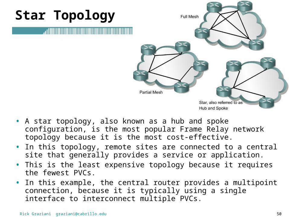
• A star topology, also known as a hub and spoke configuration, is the most popular Frame Relay network topology because it is the most cost-effective.
• In this topology, remote sites are connected to a central site that generally provides a service or application.
• This is the least expensive topology because it requires the fewest PVCs.
• In this example, the central router provides a multipoint connection, because it is typically using a single interface to interconnect multiple PVCs.

Rick Graziani [email protected] 51
Full Mesh
• In a full mesh topology, all routers have PVCs to all other destinations. • This method, although more costly than hub and spoke, provides direct
connections from each site to all other sites and allows for redundancy. • For example, when one link goes down, a router at site A can reroute
traffic through site C. • As the number of nodes in the full mesh topology increases, the
topology becomes increasingly more expensive. • The formula to calculate the total number of PVCs with a fully meshed
WAN is [n(n - 1)]/2, where n is the number of nodes.
Full Mesh Topology
Number of Number of
Connections PVCs
----------------- --------------
2 1
4 6
6 15
8 28
10 45

Rick Graziani [email protected] 52
A Frame-Relay Configuration Supporting Multiple Sites
Frame RelayNetw ork
HeadquartersHub City
Satellite Office 1Spokane
Satellite Office 2Spokomo
172.16.1.1 172.16.1.3
172.16.1.2
DLCI 101
DLCI 102
DLCI 112
DLCI 211
• This is known as a Hub and Spoke Topology, where the Hub router relays information between the Spoke routers.
• Limits the number of PVCs needed as in a full-mesh topology (coming).
Hub Router
Spoke Routers

Rick Graziani [email protected] 53
HubCityinterface Serial0ip address 172.16.1.2 255.255.255.0encapsulation frame-relay
Spokaneinterface Serial0ip address 172.16.1.1 255.255.255.0encapsulation frame-relay
Spokomointerface Serial0ip address 172.16.1.3 255.255.255.0encapsulation frame-relay
Frame RelayNetw ork
HeadquartersHub City
Satellite Office 1Spokane
Satellite Office 2Spokomo
172.16.1.1 172.16.1.3
172.16.1.2
DLCI 101
DLCI 102
DLCI 112
DLCI 211
Configuration using Inverse ARP

Rick Graziani [email protected] 55
HubCity# show frame-relay mapSerial0 (up): ip 172.16.1.1 dlci 101, dynamic, broadcast,
status defined, activeSerial0 (up): ip 172.16.1.3 dlci 112, dynamic, broadcast,
status defined, active
Spokane# show frame-relay mapSerial0 (up): ip 172.16.1.2 dlci 102, dynamic, broadcast,
status defined, active
Spokomo# show frame-relay mapSerial0 (up): ip 172.16.1.2 dlci 211, dynamic, broadcast,
status defined, active
Frame RelayNetw ork
HeadquartersHub City
Satellite Office 1Spokane
Satellite Office 2Spokomo
172.16.1.1 172.16.1.3
172.16.1.2
DLCI 101
DLCI 102
DLCI 112
DLCI 211
Configuration using Inverse ARP

Rick Graziani [email protected] 56
• Inverse ARP resolved the ip addresses for HubCity for both Spokane and Spokomo
• Inverse ARP resolved the ip addresses for Spokane for HubCity• Inverse ARP resolved the ip addresses for Spokomo for HubCity• What about between Spokane and Spokomo?
HubCity# show frame-relay mapSerial0 (up): ip 172.16.1.1 dlci 101, dynamic, broadcast,
status defined, activeSerial0 (up): ip 172.16.1.3 dlci 112, dynamic, broadcast,
status defined, active
Spokane# show frame-relay mapSerial0 (up): ip 172.16.1.2 dlci 102, dynamic, broadcast,
status defined, active
Spokomo# show frame-relay mapSerial0 (up): ip 172.16.1.2 dlci 211, dynamic, broadcast,
status defined, active
Configuration using Inverse ARP

Rick Graziani [email protected] 57
Inverse ARP Limitations
• Can HubCity ping both Spokane and Spokomo? Yes!• Can Spokane and Spokomo ping HubCity? Yes!• Can Spokane and Spokomo ping each other? No! The Spoke
routers’ serial interfaces (Spokane and Spokomo) drop the ICMP packets because there is no DLCI-to-IP address mapping for the destination address.
Solutions to the limitations of Inverse ARP1. Add an additional PVC between Spokane and Spokomo (Full Mesh)2. Configure Frame-Relay Map Statements3. Configure Point-to-Point Subinterfaces.
Frame RelayNetw ork
HeadquartersHub City
Satellite Office 1Spokane
Satellite Office 2Spokomo
172.16.1.1 172.16.1.3
172.16.1.2
DLCI 101
DLCI 102
DLCI 112
DLCI 211

Rick Graziani [email protected] 58
Reachability issues with routing updates
• An NBMA network is a multiaccess network, which means more than two nodes can connect to the network.
• Ethernet is another example of a multiaccess architecture.
• In an Ethernet LAN, all nodes see all broadcast and multicast frames.
• However, in a nonbroadcast network such as Frame Relay, nodes cannot see broadcasts of other nodes unless they are directly connected by a virtual circuit.
• This means that Branch A cannot directly see the broadcasts from Branch B, because they are connected using a hub and spoke topology.
Frame Relay is an NBMA Network

Rick Graziani [email protected] 59
Reachability issues with routing updates
• The Central router must receive the broadcast from Branch A and then send its own broadcast to Branch B.
• In this example, there are problems with routing protocols because of the split horizon rule.
• A full mesh topology with virtual circuits between every site would solve this problem, but having additional virtual circuits is more costly and does not scale well.
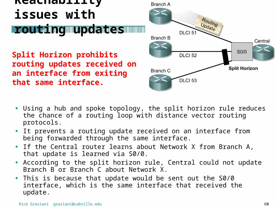
Split Horizon prohibits routing updates received on an interface from exiting that same interface.
Rick Graziani [email protected] 60
• Using a hub and spoke topology, the split horizon rule reduces the chance of a routing loop with distance vector routing protocols.
• It prevents a routing update received on an interface from being forwarded through the same interface.
• If the Central router learns about Network X from Branch A, that update is learned via S0/0.
• According to the split horizon rule, Central could not update Branch B or Branch C about Network X.
• This is because that update would be sent out the S0/0 interface, which is the same interface that received the update.
Reachability issues with routing updates
Split Horizon prohibits routing updates received on an interface from exiting that same interface.
Rick Graziani [email protected] 61
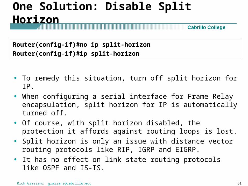
One Solution: Disable Split Horizon
• To remedy this situation, turn off split horizon for IP.
• When configuring a serial interface for Frame Relay encapsulation, split horizon for IP is automatically turned off.
• Of course, with split horizon disabled, the protection it affords against routing loops is lost.
• Split horizon is only an issue with distance vector routing protocols like RIP, IGRP and EIGRP.
• It has no effect on link state routing protocols like OSPF and IS-IS.
Router(config-if)#no ip split-horizon
Router(config-if)#ip split-horizon

Rick Graziani [email protected] 62
Another Solution for split horizon issue: subinterfaces
• To enable the forwarding of broadcast routing updates in a Frame Relay network, configure the router with subinterfaces.
• Subinterfaces are logical subdivisions of a physical interface. • In split-horizon routing environments, routing updates received on one
subinterface can be sent out on another subinterface. • With subinterface configuration, each PVC can be configured as a
point-to-point connection. • This allows each subinterface to act similar to a leased line. • This is because each point-to-point subinterface is treated as a
separate physical interface.

Rick Graziani [email protected] 63
• A key reason for using subinterfaces is to allow distance vector routing protocols to perform properly in an environment in which split horizon is activated.
• There are two types of Frame Relay subinterfaces. – Point-to-point– multipoint
Mulitpoint
Point-to-point
Rick Graziani [email protected] 64
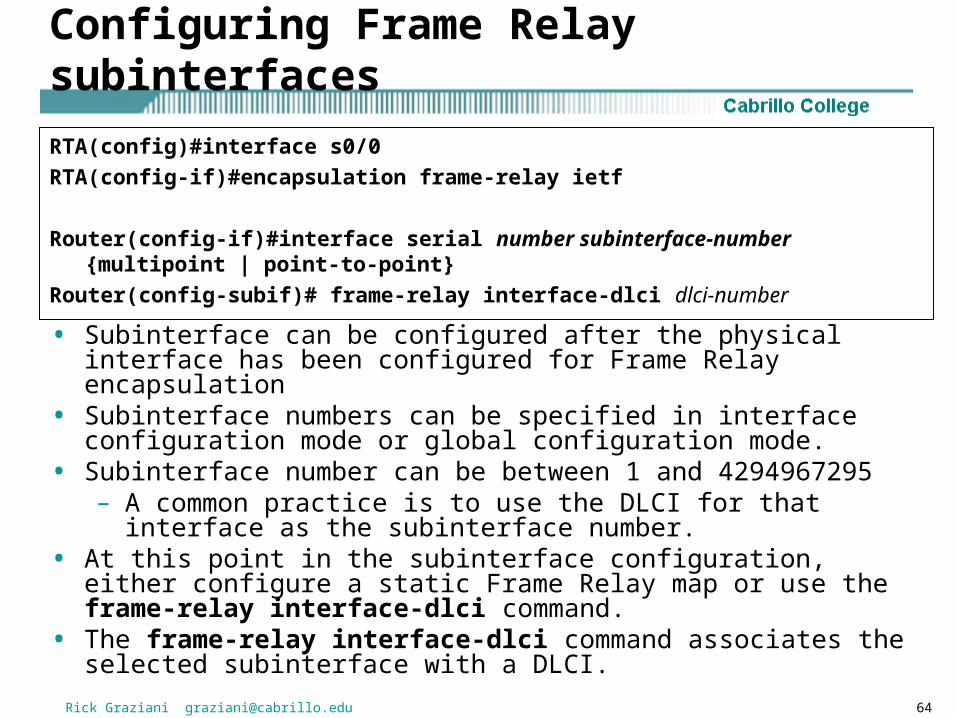
Configuring Frame Relay subinterfaces
• Subinterface can be configured after the physical interface has been configured for Frame Relay encapsulation
• Subinterface numbers can be specified in interface configuration mode or global configuration mode.
• Subinterface number can be between 1 and 4294967295– A common practice is to use the DLCI for that interface as the
subinterface number.• At this point in the subinterface configuration, either configure a static
Frame Relay map or use the frame-relay interface-dlci command.
• The frame-relay interface-dlci command associates the selected subinterface with a DLCI.
RTA(config)#interface s0/0
RTA(config-if)#encapsulation frame-relay ietf
Router(config-if)#interface serial number subinterface-number {multipoint | point-to-point}
Router(config-subif)# frame-relay interface-dlci dlci-number

Rick Graziani [email protected] 65
Show frame-relay map
Point-to-point subinterfaces are listed as a “point-to-point dlci”
Router#show frame-relay map
Serial0.1 (up): point-to-point dlci, dlci 301 (0xCB, 0x30B0), broadcast status defined, active

Rick Graziani [email protected] 66
With point-to-point subinterfaces you:
• Cannot have multiple DLCIs associated with a single point-to-point subinterface
• Cannot use frame-relay map statements
• Cannot use Inverse-ARP
• Can use the frame-relay interface dlci statement (for both point-to-point and multipoint)
Point-to-point Subinterfaces
Mulitpoint
Point-to-point

Ch. 5 – Frame Relay
CCNA 4 version 3.0
Rick Graziani
Cabrillo College