Embed Size (px)
Citation preview
Annex to ED Decision 2015/013/R
European Aviation Safety Agency
Certification Specifications
and
Guidance Material
for
Additional airworthiness specifications for operations
CS-26
Issue 1
8 May 20151
1 For the date of entry into force of this Amendment, please refer to Decision 2015/013/R in the Official Publication of
the Agency.
C-1
CONTENTS
CS-26 — ADDITIONAL AIRWORTHINESS SPECIFICATIONS FOR OPERATIONS
BOOK 1 — CERTIFICATION SPECIFICATIONS
SUBPART A — GENERAL PROVISIONS
CS 26.1 Purpose and scope
SUBPART B — LARGE AEROPLANES
CS 26.50 Seats, berths, safety belts, and harnesses
CS 26.100 Location of emergency exits
CS 26.105 Emergency exit access
CS 26.110 Emergency exit markings
CS 26.120 Interior emergency lighting and emergency light operation
CS 26.150 Compartment interiors
CS 26.155 Flammability of cargo compartment liners
CS 26.160 Lavatory fire protection
CS 26.200 Landing gear aural warning
APPENDIX F
Part l — Test Criteria and Procedures
Part II — Flammability of Seat Cushions
Part III — Test Method to Determine Flame Penetration Resistance of Cargo Compartment Liners
Part IV — Test Method to Determine the Heat Release Rate From Cabin Materials Exposed to Radiant Heat
Part V — Test Method to Determine the Smoke Emission Characteristics of Cabin Materials
BOOK 2 — GUIDANCE MATERIAL
SUBPART A — GENERAL PROVISIONS
GM1 26.1 JAR-26 / JAR/CS-25 / FAR-25+121 / OPS / Part-26 / CS-26 / GM-26 cross-reference table
GM2 26.1 Demonstration of compliance
SUBPART B — LARGE AEROPLANES
GM1 26.50(c) Cabin crew seat location with respect to injury risk
GM1 26.110(d) Universal symbolic exit signs
GM1 26.110(e)(4) Emergency Exit Markings
GM1 26.150(a) Compartment interiors
GM1 26.150(c) Compartment interiors
GM1 26.150(d) Compartment interiors
CS-26 BOOK 1
CS-26
Book 1
Certification Specifications
Additional airworthiness specifications
for operations
CS-26 BOOK 1
1-A-1
SUBPART A — GENERAL PROVISIONS
CS 26.1 Purpose and scope
This CS is the standard means to show compliance of products with the requirements of Annex I
(Part-26) to Commission Regulation (EU) 2015/640.(See GM1 26.1 and GM2 26.1)
CS-26 BOOK 1
1-B-1
SUBPART B — LARGE AEROPLANES
CS 26.50 Seats, berths, safety belts, and harnesses
Compliance with Part 26.50 is demonstrated by complying with CS 25.785(g), (h), (j) & (k), or
equivalent or with the following:
(a) Each seat at a flight deck station is equipped with a combined safety belt and shoulder harness
with a single-point release that permits the flight deck occupant, when seated with safety belt
and shoulder harness fastened, to perform all of the occupant’s necessary flight deck
functions. There must be a means to secure each combined safety belt and shoulder harness,
when not in use, to prevent interference with the operation of the aeroplane and with rapid
egress in an emergency. Shoulder harness and combined safety belt and shoulder harness that
were approved and installed prior to 6 March 1980 may continue to be used. Safety belt and
shoulder harness restraint systems may be designed to the inertia load factors established
under the certification basis of the aeroplane.
(b) Each seat for a cabin crew member required by Part-ORO.CC.100, located in passenger
compartments:
(1) is equipped with a restraint system consisting of a combined safety belt and shoulder
harness unit with a single point release. Each combined safety belt and shoulder harness
is equipped with a means to secure it, when not in use, to prevent interference with
rapid egress in an emergency;
(2) to the extent possible, without compromising their proximity to required floor level
emergency exits, is located to provide a direct view of the cabin area for which the cabin
crew member is individually responsible, except that for aeroplanes with a certification
basis prior to JAR 25.785 at Change 8 (or FAR Part 25, §25.785, at Amendment 25-51
respectively), cabin crew member seats need not be re-located to meet that condition if
an indirect view into the passenger cabin is given by a mirror;
(3) is:
(i) either forward or rearward facing, with an energy absorbing rest that is designed
to support the arms, shoulders, head, and spine; and
(ii) positioned so that when not in use they do not interfere with the use of
passageways and exits.
Combined safety belt and shoulder harness that were approved and installed prior to 6 March
1980 may continue to be used. Safety belt and shoulder harness restraint systems may be
designed to the inertia load factors established under the certification basis of the aeroplane.
(c) Each seat for a cabin crew member required by Part-ORO.CC.100, is located to minimise the
probability of its occupant suffering injury by being struck by items dislodged in a galley, or
from a stowage compartment or serving cart. All items expected in these locations in service
are considered. (See GM1 26.50(c))
(d) Each occupant of a seat that makes more than an 18-degree angle with the vertical plane
containing the aeroplane centreline is protected from head injury by a safety belt and an
energy absorbing rest that will support the arms, shoulders, head and spine, or by a safety belt
CS-26 BOOK 1
1-B-2
and shoulder harness that prevents the head from contacting any injurious object. Each
occupant of any other seat is protected from head injury by a safety belt and, as appropriate to
the type, location, and angle of facing of each seat, by one or more of the following:
(1) a shoulder harness that will prevent the head from contacting any injurious object;
(2) the elimination of any injurious object within striking radius of the head;
(3) an energy absorbing rest that will support the arms, shoulders, head, and spine.
CS 26.100 Location of emergency exits
Compliance with Part 26.100 is demonstrated by complying with the following:
If one or more emergency exits are deactivated, the distance(s) between the remaining exits is (are)
no more than 18.3 m (60 feet) from any adjacent passenger emergency exit on the same side of the
same deck of the fuselage, as measured parallel to the aeroplane’s longitudinal axis between the
nearest exit edges.
CS 26.105 Emergency exit access
Compliance with Part 26.105 is demonstrated by complying with CS 25.813(d) to (f) or equivalent, or
with the following:
(a) Reserved.
(b) If it is necessary to pass through a passageway between passenger compartments to reach any
required emergency exit from any seat in the passenger cabin, the passageway is
unobstructed. However, curtains may be used if they allow free entry through the passageway.
(c) No door is installed in any partition between passenger compartments.
(d) If it is necessary to pass through a doorway separating the passenger cabin from other areas to
reach any required emergency exit from any passenger seat, the door has a means to latch it in
the open position. The latching means withstands the loads imposed upon it when the door is
subjected to the ultimate inertia forces, relative to the surrounding structure, prescribed in CS
25.561(b), or equivalent, at the amendment level specified in the relevant Type Certificate
Data Sheet, or equivalent document.
CS 26.110 Emergency exit markings
Compliance with Part 26.110 is demonstrated by complying with CS 25.811(a) to (d), and (f)&(g), or
equivalent, and CS 25.811(e) or equivalent, or with the following:
(a) Each passenger emergency exit, its means of access, and its means of opening are
conspicuously marked.
(b) The identity and location of each passenger emergency exit is recognisable from a distance
equal to the width of the cabin.
(c) Means are provided to assist the occupants in locating the exits in conditions of dense smoke.
(d) The location of each passenger emergency exit is indicated by a sign visible to occupants
approaching along the main passenger aisle (or aisles). There is:
CS-26 BOOK 1
1-B-3
(1) a passenger emergency exit locator sign above the aisle (or aisles) near each passenger
emergency exit, or at another overhead location if it is more practical because of low
headroom, except that one sign may serve more than one exit if each exit can be seen
readily from the sign;
(2) a passenger emergency exit marking sign next to each passenger emergency exit, except
that one sign may serve two such exits if they can both be seen readily from the sign;
and
(3) a sign on each bulkhead or divider that prevents fore and aft vision along the passenger
cabin to indicate emergency exits beyond and obscured by the bulkhead or divider,
except that if this is not possible, the sign may be placed at another appropriate
location.
Each sign listed in this sub-paragraph may use the word ‘exit’ in its legend in place of the term
‘emergency exit’ or a universal symbolic exit sign. The design of the exit signs is chosen to
provide a consistent set throughout the cabin. (See GM1 26.110(d))
(e) The location of the operating handle and instructions for opening exits from the inside of the
aeroplane are clearly shown in the following manner:
(1) each passenger emergency exit has, on or near the exit, a marking that is readable from
a distance of 76 cm (30 inches);
(2) each passenger emergency exit operating handle and the cover removal instructions, if
the handle is covered, are:
(i) self-illuminated with an initial brightness of at least 0.51 candela/m2 (160 micro-
lamberts); or
(ii) conspicuously located and well illuminated by the emergency lighting even in
conditions of occupant crowding at the exit.
(3) Reserved
(4) All Type II and larger passenger emergency exits with a locking mechanism released by
motion of a handle, are marked by a red arrow with a shaft at least 19 mm (0.75 inch)
wide, adjacent to the handle, that indicates the full extent and direction of the unlocking
motion required. The word OPEN is horizontally situated adjacent to the arrow head and
is in red capital letters at least 25 mm (1 inch) high. The arrow and word OPEN are
located on a background which provides adequate contrast. (See GM1 26.110(e)(4))
(f) Each emergency exit that is openable from the outside, and its means of opening is marked on
the outside of the aeroplane. In addition, the following apply:
(1) The outside marking for each passenger emergency exit in the side of the fuselage
includes one 5 cm (2 inch) coloured band outlining the exit.
(2) Each outside marking including the band, has colour contrast to be readily
distinguishable from the surrounding fuselage surface. The contrast is such that if the
reflectance of the darker colour is 15% or less, the reflectance of the lighter colour is at
least 45%. ‘Reflectance’ is the ratio of the luminous flux reflected by a body to the
luminous flux it receives. When the reflectance of the darker colour is greater than 15%,
CS-26 BOOK 1
1-B-4
at least a 30% difference between its reflectance and the reflectance of the lighter
colour is provided.
(3) In the case of exits other than those in the side of the fuselage, such as ventral or tail
cone exits, the external means of opening, including instructions if applicable, are
conspicuously marked in red, or bright chrome yellow if the background colour is such
that red is inconspicuous. When the opening is located on only one side of the fuselage,
a conspicuous marking to that effect is provided on the other side.
CS 26.120 Interior emergency lighting and emergency light operation
Compliance with Part 26.120 is demonstrated by complying with CS 25.812 (b),(c),(d) &(h) or
equivalent and CS 25.812 (a) and (e) or equivalent, or with the following:
(a) An emergency lighting system, independent of the main lighting system, is installed. However,
sources of general cabin illumination may be common to both the emergency and the main
lighting system if the power supply to the emergency lighting system is independent of the
power supply to the main lighting system. The emergency lighting system includes:
(1) Illuminated emergency exit marking and locating signs, sources of general cabin
illumination and interior lighting in emergency exit areas.
(2) for aeroplanes that have a maximum approved passenger seating configuration of more
than 19, a floor proximity emergency escape path marking provides emergency
evacuation guidance for passengers when all sources of illumination more than 1.22 m
(4 feet) above the cabin aisle floor are totally obscured. In the dark of the night, the floor
proximity emergency escape path marking enables each passenger to:
(i) after leaving the passenger seat, visually identify the emergency escape path
along the cabin aisle floor to the first exits or pair of exits forward and aft of the
seat;
(ii) readily identify each exit from the emergency escape path by reference only to
markings and visual features not more than 1.22 m (4 feet) above the cabin floor.
(b) Except for lights forming part of the emergency lighting subsystems provided in compliance
with Part CAT.IDE.A.275 (b)(4) and (5) that serve no more than one assist means, are
independent of the aeroplane’s main emergency lighting systems, and are automatically
activated when the assist means is deployed, each light required for interior and exterior
emergency lighting:
(1) is operable manually both from the flight crew station and for aeroplanes on which a
cabin crew member is required, from a point in the passenger compartment that is
readily accessible from a normal cabin crew seat;
(2) has a means to prevent inadvertent operation of the manual controls;
(3) when armed or turned on at either station, remains lighted or becomes lighted upon
interruption of the aeroplane’s normal electric power;
(4) provides the required level of illumination for at least 10 minutes at the critical ambient
conditions after emergency landing;
CS-26 BOOK 1
1-B-5
(5) has a cockpit control device that has an ‘on’, ‘off’, and ‘armed’ position.
(c) In addition to subparagraphs (a), and (b) above, for an aeroplane which had its initial
Certificate of Airworthiness issued prior to 1 December 2006, the following conditions are met:
(1) For an aeroplane for which the application for the type certificate was filed prior to 1
May 1972:
(i) Each passenger emergency exit marking and each locating sign has white letters
at least 25 mm (1 inch) high on a red background at least 5 cm (2 inches) high.
These signs may be internally electrically illuminated, or self-illuminated by other
than electrical means, with an initial brightness of at least 0.509 cd/m2 (160
microlamberts). The colours may be reversed in the case of internally electrically
illuminated signs if this will increase the illumination of the exit. On these
aeroplanes, no sign may continue to be used if its luminescence (brightness)
decreases to below 0.318 cd/m2 (100 microlamberts).
(ii) The sources of general cabin illumination provides enough general lighting in the
passenger cabin so that the average illumination when measured at 102 cm (40-
inch) intervals at seat armrest height, on the centreline of the main passenger
aisle, is at least 0.54 lux (0.05 foot-candle).
(iii) The floor of the passageway leading to each floor level passenger emergency exit,
between the main aisles and the exit openings is provided with illumination.
(2) For an aeroplane for which the application for the type certificate was filed on or after 1
May 1972, the interior emergency lighting specifications under which the aeroplane was
type certificated. On these aeroplanes, no sign may continue to be used if its
luminescence (brightness) decreases to below 0.796 cd/m2 (250 microlamberts).
(d) In addition to subparagraphs (a) and (b) above, for an aeroplane which had its initial Certificate
of Airworthiness issued on or after 1 December 2006, and for which the application for the
type certificate was filed prior to 1 May 1972, the following conditions are met:
(1) For an aeroplane that has a passenger seating configuration, excluding pilot seats, of:
(i) 10 seats or more, each passenger emergency exit locator sign and marking sign
required by Part 26.110(d) has red letters at least 38 mm (1 ½ inches) high on an
illuminated white background, and has an area of at least 135 cm2 (21 square
inches) excluding the letters. The lighted background-to-letter contrast is at least
10:1. The letter height to stroke-width ratio are not more than 7:1 nor less than
6:1. These signs are internally electrically illuminated with a background
brightness of at least 86 cd/m2 (25 foot-lamberts) and a high-to-low background
contrast no greater than 3:1. Other passenger emergency exit signs required by
Part 26.110(d) have red letters at least 38 mm (1 ½ inches) high on a white
background having an area of at least 135 cm2 (21 square inches) excluding the
letters. These signs are internally, electrically illuminated or self-illuminated by
other than electrical means and have an initial brightness of at least 1.27 cd/m2
(400 microlamberts). The colours are reversed in the case of a sign that is self-
illuminated by other than electrical means. On these aeroplanes, no sign
CS-26 BOOK 1
1-B-6
continues to be used if its luminescence (brightness) decreases to below 0.796
cd/m2 (250 microlamberts).
(ii) 9 seats or less, passenger emergency exit signs that are required by Part
26.110(d), have red letters at least 25 mm (1 inch) high on a white background at
least 5 cm (2 inches) high. These signs may be internally electrically illuminated or
self-illuminated by other than electrical means, with an initial brightness of at
least 0.509 cd/m2 (160 microlamberts). The colours may be reversed in the case
of a sign that is self-illuminated by other than electrical means. On these
aeroplanes, no sign continues to be used if its luminescence (brightness)
decreases to below 0.318 cd/m2 (100 microlamberts).
(2) General illumination in the passenger cabin is provided so that when measured along
the centreline of the main passenger aisle(s), and cross aisle(s) between main aisles, at
seat armrest height and at 102 cm (40-inch) intervals, the average illumination is not less
than 0.54 lux (0.05 foot-candle) and the illumination at each 102 cm (40-inch) interval is
not less than 0.11 lux (0.01 foot-candle). A main passenger aisle is considered to extend
along the fuselage from the most forward passenger emergency exit or cabin occupant
seat, whichever is farther forward, to the most rearward passenger emergency exit or
cabin occupant seat, whichever is farther aft.
(3) The floor of the passageway leading to each floor-level passenger emergency exit,
between the main aisles and exit openings, is provided with illumination that is not less
than 0.22 lux (0.02 foot-candle) measured along a line that is within 15 cm (six inches) of
and parallel to the floor and is centred on the passenger evacuation path.
(e) Each sign required by Part 26.120 may use a universal symbolic exit sign. The design of the
signs is chosen to provide a consistent set throughout the cabin. (See GM1 26.110(d))
CS 26.150 Compartment interiors
Compliance with Part 26.150 is demonstrated by complying with CS 25.853 and Appendix F or
equivalent, CS 25.853(e) or equivalent and CS 25.791 or equivalent or with the following:
For each compartment occupied by the crew or passengers the following apply:
(a) Upon any major replacement of any individual group of components as specified in Appendix
F, Part I, sub-paragraph (a)(1)(i), such as interior ceiling panels, wall panels, etc., this individual
group of components complies with Appendix F, Part I of this CS 26. (See GM1 26.150(a))
(b) Seat cushions, except those on flight crew member seats, on large aeroplanes, type
certificated after 1 January 1958, comply with the fire protection specifications of Appendix F,
Part II.
(c) (1) Heat release (other than for lavatory interiors or flight deck), for interior ceiling and wall
panels (other than lighting lenses), partitions, and the outer surfaces of galleys, large
cabinets and stowage compartments (other than underseat stowage compartments and
compartments for stowing small items, such as magazines and maps), in large
aeroplanes which had their initial Certificate of Airworthiness issued on or after 20
August 1988, but prior to 20 August 1990, and having a MOPSC of more than 19, comply
with the heat release rate testing provisions of Appendix F Part IV, except that the total
CS-26 BOOK 1
1-B-7
heat release over the first two minutes of sample exposure does not exceed 100
kilowatt-minutes per square metre, and the peak heat release rate does not exceed 100
kilowatts per square metre.
(2) Heat release and smoke density (other than for lavatory interiors or flight deck) for
interior ceiling and wall panels (other than lighting lenses), partitions, and the outer
surfaces of galleys, large cabinets and stowage compartments (other than underseat
stowage compartments and compartments for stowing small items, such as magazines
and maps), in large aeroplanes, having a MOPSC of more than 19, which had their initial
Certificate of Airworthiness issued on or after 20 August 1990, comply with the heat
release and smoke density specifications of Appendix F Parts IV & V. (See GM1
26.150(c))
(d) Large aeroplanes having a MOPSC of more than 19, Type Certificated after 1 January 1958
upon the first substantially complete replacement of the cabin interior components, (i.e.
interior ceiling and wall panels (other than lighting lenses), partitions, and the outer surfaces of
galleys, large cabinets and stowage compartments (other than underseat stowage
compartments and compartments for stowing small items, such as magazines and maps)),
comply with the heat release and smoke density specifications of Appendix F Parts IV & V. (See
GM1 26.150(d))
(e) Smoking prohibition is indicated by a placard so stating.
(f) Each disposal receptacle for towels, paper or waste is fully enclosed and constructed of
materials adequate in resistance to fire such that any fire likely to occur in it under normal use
is contained. The ability of the disposal receptacle to contain those fires under all probable
conditions of wear, misalignment, and ventilation expected in service is demonstrated by test
unless appropriate maintenance tasks are put in place to ensure that excess wear or
misalignment are quickly repaired. A placard containing the legible words or symbology
indicating ‘No Cigarette Disposal’ is located on or near each disposal receptacle door.
CS 26.155 Flammability of cargo compartment liners
Compliance with Part 26.155 is demonstrated by complying with CS 25.855 & Appendix F Part III, or
equivalent or with the following:
(a) Large aeroplanes, Type Certificated after 1 January 1958, with Class C or D compartment,
greater than 5.66 m3 (200 cubic feet) have ceiling and sidewall liner panels which are
constructed of:
(1) glass fibre reinforced resin, or
(2) materials which meet the flame penetration test specifications of Appendix F Part III, or
other equivalent methods, or
(3) aluminium (only in the case of aluminium liner installations approved prior to 1 July
1989).
(b) For compliance with this paragraph, the term ‘liner’ includes any design features, such as a
joint or fastener which would affect the capability of the liner to safely contain a fire.
CS-26 BOOK 1
1-B-8
CS 26.160 Lavatory fire protection
Compliance with Part 26.160 is demonstrated by complying with CS 25.854, or equivalent or with the
following:
(a) Each lavatory is equipped with a smoke detector system or equivalent that provides a warning
light in the cockpit, or provides a warning light or audible warning in the passenger cabin that
would be readily detected by a cabin crew member; and
(b) Each lavatory is equipped with a built-in fire extinguisher for each disposal receptacle for
towels, paper, or waste, located within the lavatory. The extinguisher is designed to discharge
automatically into each disposal receptacle upon occurrence of a fire in that receptacle.
CS 26.200 Landing gear aural warning
Compliance with Part 26.200 is demonstrated by complying with CS 25.729, or equivalent or with the
following:
(a) Large aeroplanes have a landing gear aural warning device that functions continuously under
the following conditions:
(1) For aeroplanes with an established approach flap position, whenever the flaps are
extended beyond the maximum certificated approach climb configuration position in
the Aeroplane Flight Manual and the landing gear is not fully extended and locked.
(2) For aeroplanes without an established approach climb flap position, whenever the flaps
are extended beyond the position at which landing gear extension is normally
performed and the landing gear is not fully extended and locked.
(b) The warning system of sub-paragraph (a) of this paragraph:
(1) does not have a manual shut-off means readily available to the flight crew such that it
could be operated instinctively, inadvertently or by habitual reflexive action;
(2) is, in addition to the throttle-actuated device, installed under the airworthiness type
certification specifications; and
(3) may utilise any part of the throttle-actuated system, including the aural warning device.
(c) The flap position sensing unit may be installed at any suitable place in the aeroplane.
CS-26 BOOK 1
1-APP-1
APPENDIX F
Part l — Test Criteria and Procedures
Refer to CS-25 Appendix F Part I initial issue or later amendments.
Part II — Flammability of Seat Cushions
Refer to CS-25 Appendix F Part II initial issue or later amendments.
Part III — Test Method to Determine Flame Penetration Resistance of Cargo Compartment Liners
Refer to CS-25 Appendix F Part III initial issue or later amendments.
Part IV — Test Method to Determine the Heat Release Rate From Cabin Materials Exposed to Radiant Heat
Refer to CS-25 Appendix F Part IV initial issue or later amendments.
Part V — Test Method to Determine the Smoke Emission Characteristics of Cabin Materials
Refer to CS-25 Appendix F Part V initial issue or later amendments.
CS-26 BOOK 2
CS-26
Book 2
Guidance Material
Additional airworthiness specifications
for operations
CS-26 BOOK 2
2-GEN-1
1 PRESENTATION
1.1 A numbering system has been used in which the Guidance Material uses the same number as the paragraph in Book 1 to which it refers. The number is introduced by the letters GM to distinguish the material from Book 1.
CS-26 BOOK 2
2-A-1
SUBPART A — GENERAL PROVISIONS
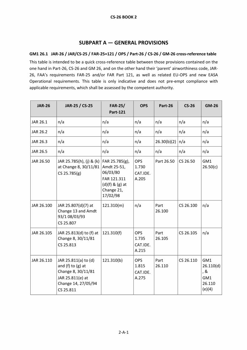
GM1 26.1 JAR-26 / JAR/CS-25 / FAR-25+121 / OPS / Part-26 / CS-26 / GM-26 cross-reference table
This table is intended to be a quick cross-reference table between those provisions contained on the
one hand in Part-26, CS-26 and GM 26, and on the other hand their ‘parent’ airworthiness code, JAR-
26, FAA’s requirements FAR-25 and/or FAR Part 121, as well as related EU-OPS and new EASA
Operational requirements. This table is only indicative and does not pre-empt compliance with
applicable requirements, which shall be assessed by the competent authority.
JAR-26 JAR-25 / CS-25 FAR-25/
Part-121
OPS Part-26 CS-26 GM-26
JAR 26.1 n/a n/a n/a n/a n/a n/a
JAR 26.2 n/a n/a n/a n/a n/a n/a
JAR 26.3 n/a n/a n/a 26.30(b)(2) n/a n/a
JAR 26.5 n/a n/a n/a n/a n/a n/a
JAR 26.50 JAR 25.785(h), (j) & (k) at Change 8, 30/11/81
CS 25.785(g)
FAR 25.785(g), Amdt 25-51, 06/03/80
FAR 121.311 (d)(f) & (g) at Change 21, 17/02/98
OPS 1.730
CAT.IDE.A.205
Part 26.50 CS 26.50 GM1 26.50(c)
JAR 26.100 JAR 25.807(d)(7) at Change 13 and Amdt 93/1 08/03/93
CS 25.807
121.310(m) n/a Part 26.100
CS 26.100 n/a
JAR 26.105 JAR 25.813(d) to (f) at Change 8, 30/11/81
CS 25.813
121.310(f) OPS 1.735
CAT.IDE.A.215
Part 26.105
CS 26.105 n/a
JAR 26.110 JAR 25.811(a) to (d) and (f) to (g) at Change 8, 30/11/81
JAR 25.811(e) at Change 14, 27/05/94
CS 25.811
121.310(b) OPS 1.815
CAT.IDE.A.275
Part 26.110
CS 26.110 GM1 26.110(d), &
GM1 26.110 (e)(4)
CS-26 BOOK 2
2-A-2
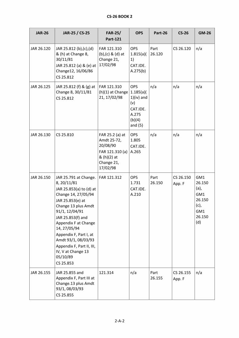
JAR-26 JAR-25 / CS-25 FAR-25/
Part-121
OPS Part-26 CS-26 GM-26
JAR 26.120 JAR 25.812 (b),(c),(d) & (h) at Change 8, 30/11/81
JAR 25.812 (a) & (e) at Change12, 16/06/86
CS 25.812
FAR 121.310 (b),(c) & (d) at Change 21, 17/02/98
OPS 1.815(a)(1)
CAT.IDE.A.275(b)
Part 26.120
CS 26.120 n/a
JAR 26.125 JAR 25.812 (f) & (g) at Change 8, 30/11/81
CS 25.812
FAR 121.310 (h)(1) at Change 21, 17/02/98
OPS 1.185(a)(1)(iv) and (v)
CAT.IDE.A.275 (b)(4) and (5)
n/a n/a n/a
JAR 26.130 CS 25.810 FAR 25.2 (a) at Amdt 25-72, 20/08/90
FAR 121.310 (a) & (h)(2) at Change 21, 17/02/98
OPS 1.805
CAT.IDE.A.265
n/a n/a n/a
JAR 26.150 JAR 25.791 at Change. 8, 20/11/81
JAR 25.853(a) to (d) at Change 14, 27/05/94
JAR 25.853(e) at Change 13 plus Amdt 91/1, 12/04/91
JAR 25.853(f) and Appendix F at Change 14, 27/05/94
Appendix F, Part I, at Amdt 93/1, 08/03/93
Appendix F, Part II, III, IV, V at Change 13 05/10/89
CS 25.853
FAR 121.312 OPS 1.731
CAT.IDE.A.210
Part 26.150
CS 26.150
App. F
GM1 26.150 (a),
GM1 26.150 (c),
GM1 26.150 (d)
JAR 26.155 JAR 25.855 and Appendix F, Part III at Change.13 plus Amdt 93/1, 08/03/93
CS 25.855
121.314 n/a Part 26.155
CS 26.155
App. F
n/a
CS-26 BOOK 2
2-A-3
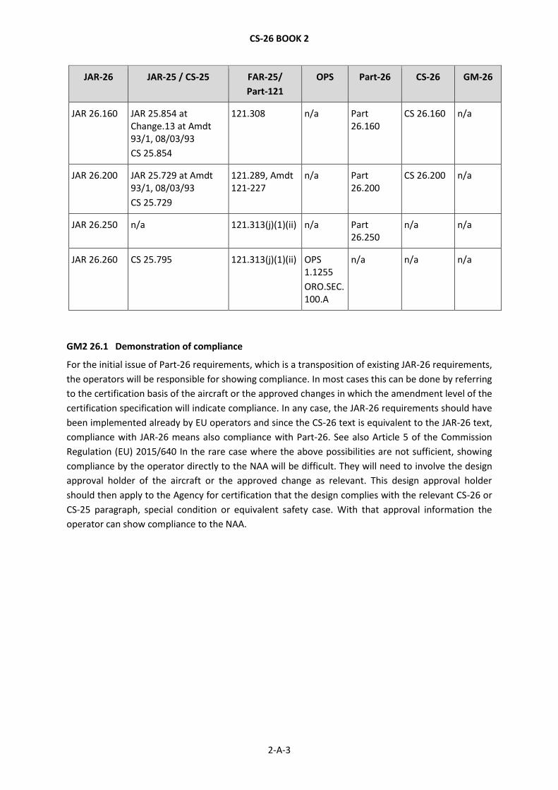
JAR-26 JAR-25 / CS-25 FAR-25/
Part-121
OPS Part-26 CS-26 GM-26
JAR 26.160 JAR 25.854 at Change.13 at Amdt 93/1, 08/03/93
CS 25.854
121.308 n/a Part 26.160
CS 26.160 n/a
JAR 26.200 JAR 25.729 at Amdt 93/1, 08/03/93
CS 25.729
121.289, Amdt 121-227
n/a Part 26.200
CS 26.200 n/a
JAR 26.250 n/a 121.313(j)(1)(ii) n/a Part 26.250
n/a n/a
JAR 26.260 CS 25.795 121.313(j)(1)(ii) OPS 1.1255
ORO.SEC.100.A
n/a n/a n/a
GM2 26.1 Demonstration of compliance
For the initial issue of Part-26 requirements, which is a transposition of existing JAR-26 requirements,
the operators will be responsible for showing compliance. In most cases this can be done by referring
to the certification basis of the aircraft or the approved changes in which the amendment level of the
certification specification will indicate compliance. In any case, the JAR-26 requirements should have
been implemented already by EU operators and since the CS-26 text is equivalent to the JAR-26 text,
compliance with JAR-26 means also compliance with Part-26. See also Article 5 of the Commission
Regulation (EU) 2015/640 In the rare case where the above possibilities are not sufficient, showing
compliance by the operator directly to the NAA will be difficult. They will need to involve the design
approval holder of the aircraft or the approved change as relevant. This design approval holder
should then apply to the Agency for certification that the design complies with the relevant CS-26 or
CS-25 paragraph, special condition or equivalent safety case. With that approval information the
operator can show compliance to the NAA.
CS-26 BOOK 2
2-B-1
SUBPART B — LARGE AEROPLANES
GM1 26.50(c) Cabin crew seat location with respect to injury risk
AC 25.785-1B, Section 8 is applicable when showing compliance with CS 26.50(c).
GM1 26.110(d) Universal symbolic exit signs
Guidance on the use of universal symbolic exit signs can be found in AMC 25.812(b)(1).
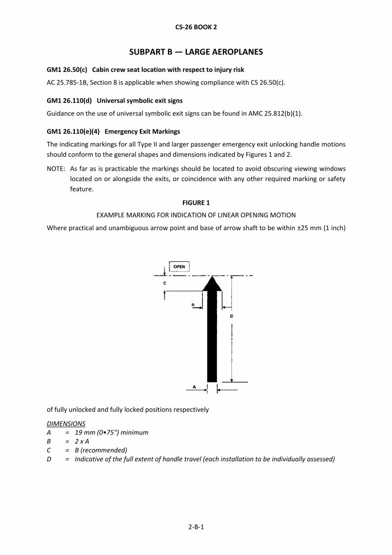
GM1 26.110(e)(4) Emergency Exit Markings
The indicating markings for all Type II and larger passenger emergency exit unlocking handle motions
should conform to the general shapes and dimensions indicated by Figures 1 and 2.
NOTE: As far as is practicable the markings should be located to avoid obscuring viewing windows
located on or alongside the exits, or coincidence with any other required marking or safety
feature.
FIGURE 1
EXAMPLE MARKING FOR INDICATION OF LINEAR OPENING MOTION
Where practical and unambiguous arrow point and base of arrow shaft to be within ±25 mm (1 inch)
of fully unlocked and fully locked positions respectively
DIMENSIONS A = 19 mm (0•75") minimum B = 2 x A C = B (recommended) D = Indicative of the full extent of handle travel (each installation to be individually assessed)
CS-26 BOOK 2
2-B-2
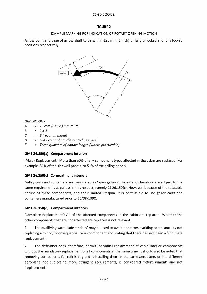
FIGURE 2
EXAMPLE MARKING FOR INDICATION OF ROTARY OPENING MOTION
Arrow point and base of arrow shaft to be within ±25 mm (1 inch) of fully unlocked and fully locked positions respectively
DIMENSIONS A = 19 mm (0•75") minimum B = 2 x A C = B (recommended) D = Full extent of handle centreline travel E = Three quarters of handle length (where practicable)
GM1 26.150(a) Compartment interiors
‘Major Replacement’: More than 50% of any component types affected in the cabin are replaced. For
example, 51% of the sidewall panels, or 51% of the ceiling panels.
GM1 26.150(c) Compartment interiors
Galley carts and containers are considered as ‘open galley surfaces’ and therefore are subject to the
same requirements as galleys in this respect, namely CS 26.150(c). However, because of the rotatable
nature of these components, and their limited lifespan, it is permissible to use galley carts and
containers manufactured prior to 20/08/1990.
GM1 26.150(d) Compartment interiors
‘Complete Replacement’: All of the affected components in the cabin are replaced. Whether the
other components that are not affected are replaced is not relevant.
1 The qualifying word ‘substantially’ may be used to avoid operators avoiding compliance by not
replacing a minor, inconsequential cabin component and stating that there had not been a ‘complete
replacement’.
2 The definition does, therefore, permit individual replacement of cabin interior components
without the mandatory replacement of all components at the same time. It should also be noted that
removing components for refinishing and reinstalling them in the same aeroplane, or in a different
aeroplane not subject to more stringent requirements, is considered ‘refurbishment’ and not
‘replacement’.

![Certification Specifications and Guidance Material …...[Issue: 26/2] CS 26.60 Emergency landing — dynamic conditions Compliance with 26.60 of Part-26 is demonstrated by complying](https://img.dokumen.tips/doc/110x75/5f8275a516695d2ab729e3e4/certification-specifications-and-guidance-material-issue-262-cs-2660-emergency.jpg)