Embed Size (px)
Citation preview
Centrifugal Pumps Gas handling combi pump in segmental design UEA 5002 … 10015
PUMP TECHNOLOGY SIHI UEA
133.83201.59.01 E 09/2011
Technical Data Output: max. 220 m³/h Differential pressure: max. 20 bar Speed: max. 3600 rpm Temperature: -40°C to +80°C Casing pressure: PN 40 up to size 8000 PN 25 size 10000 Shaft sealing: mechanical seal Flange connections: DIN EN 1092 PN 25 or PN 40 Option: ASME B 16.5 Sense of rotation: clockwise, when seen from the drive on the pump Certification: ATEX 94/9/EG, Ex II 2 G c T4-T5 GOST Application Gas handling centrifugal pumps of the series UEA are used for trouble-free handling of pure or turbid, not aggressive liquids, containing no solids. The gas handling capability is used to handle mainly liquid gas (LPG) and other hydrocarbon liquidate reshipment points and large gas depots, fire extinguishing plants sprinkling and irrigation plants emptying of fuel trucks filling of high tanks, refueling cars. Centrifugal pumps of the series UEA with special NPSH inducer stage are applied for trouble-free pumping under unfavorable conditions at suction side. A special priming stage is able to absorb eventually existing vapour from the suction side. The capability of the pumps in this series to handle liquids at the boiling point, allows a wide-ranging application when handling: • LPG • Hydrocarbon condensates • Hydrocarbon liquefied gases
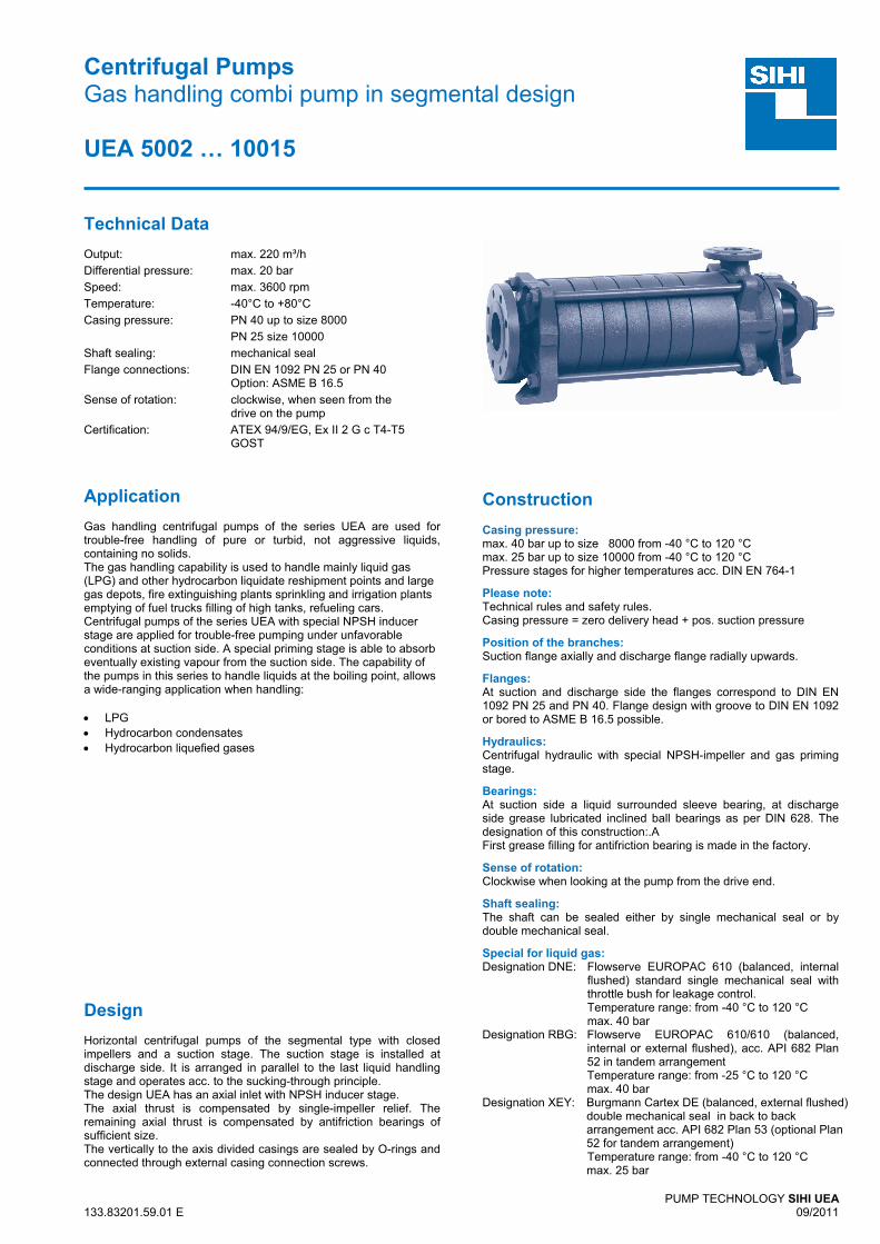
Design Horizontal centrifugal pumps of the segmental type with closed impellers and a suction stage. The suction stage is installed at discharge side. It is arranged in parallel to the last liquid handling stage and operates acc. to the sucking-through principle. The design UEA has an axial inlet with NPSH inducer stage. The axial thrust is compensated by single-impeller relief. The remaining axial thrust is compensated by antifriction bearings of sufficient size. The vertically to the axis divided casings are sealed by O-rings and connected through external casing connection screws.
Construction Casing pressure: max. 40 bar up to size 8000 from -40 °C to 120 °C max. 25 bar up to size 10000 from -40 °C to 120 °C Pressure stages for higher temperatures acc. DIN EN 764-1
Please note: Technical rules and safety rules. Casing pressure = zero delivery head + pos. suction pressure
Position of the branches: Suction flange axially and discharge flange radially upwards.
Flanges: At suction and discharge side the flanges correspond to DIN EN 1092 PN 25 and PN 40. Flange design with groove to DIN EN 1092 or bored to ASME B 16.5 possible.
Hydraulics: Centrifugal hydraulic with special NPSH-impeller and gas priming stage.
Bearings: At suction side a liquid surrounded sleeve bearing, at discharge side grease lubricated inclined ball bearings as per DIN 628. The designation of this construction:.A First grease filling for antifriction bearing is made in the factory.
Sense of rotation: Clockwise when looking at the pump from the drive end.
Shaft sealing: The shaft can be sealed either by single mechanical seal or by double mechanical seal.
Special for liquid gas: Designation DNE: Flowserve EUROPAC 610 (balanced, internal
flushed) standard single mechanical seal with throttle bush for leakage control. Temperature range: from -40 °C to 120 °C max. 40 bar
Designation RBG: Flowserve EUROPAC 610/610 (balanced, internal or external flushed), acc. API 682 Plan 52 in tandem arrangement Temperature range: from -25 °C to 120 °C max. 40 bar
Designation XEY: Burgmann Cartex DE (balanced, external flushed) double mechanical seal in back to back arrangement acc. API 682 Plan 53 (optional Plan 52 for tandem arrangement) Temperature range: from -40 °C to 120 °C max. 25 bar
SIHI UEA
2
Sectional drawing and nomenclatures
UEA with balanced single mechanical seal DNE with throttle bush UEA with XEY, Cartex (PN25) double mechanicals seal UEA with RBG, (PN40) double mechanicals seal
Arrangement: Arrangement: ‘Back to back’ API 682 plan 53 or optional ‘Tandem’ API 682 plan 52 ‘Tandem‘ API 682 plan 52
Special NPSH inducer impeller Special gas absorber stage
SIHI UEA
3
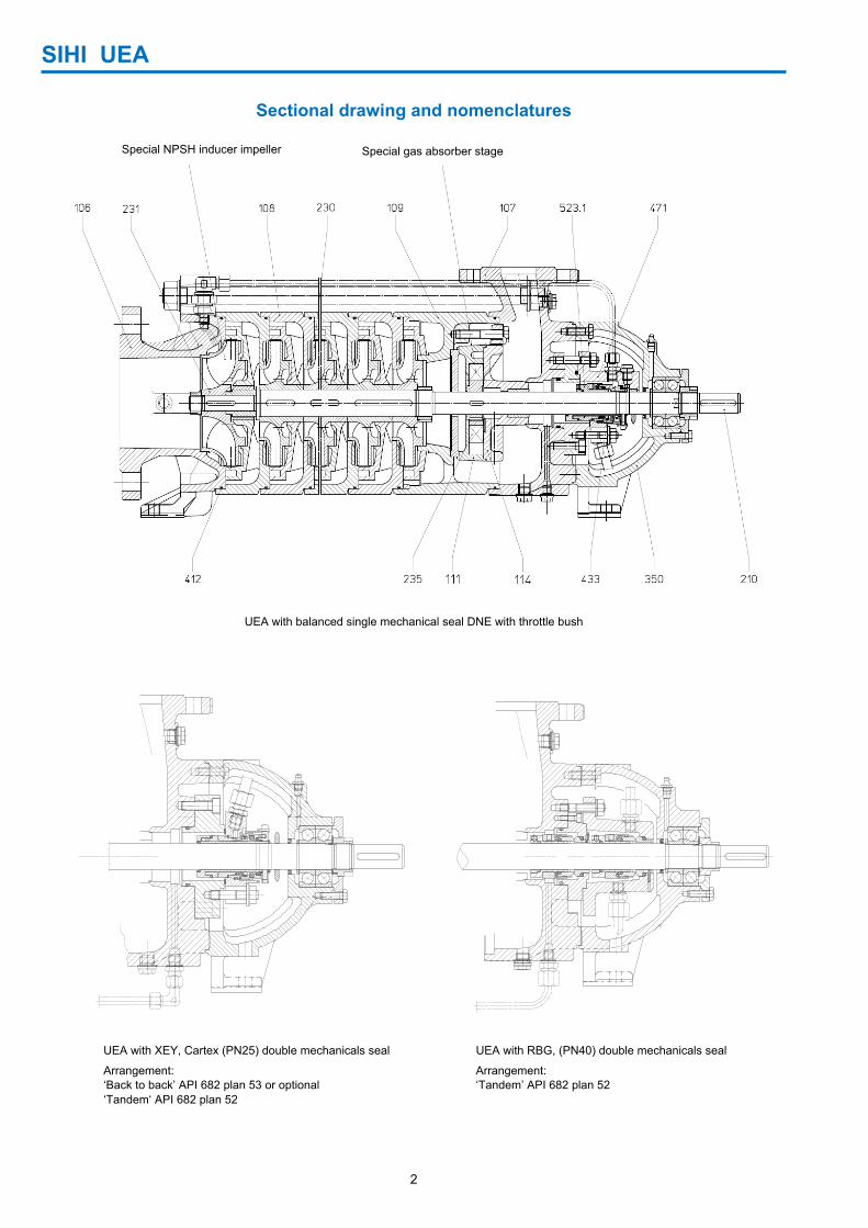
Material design:
Item COMPONENTS MATERIAL DESIGN
1A 2C
106 Suction casing
EN-JS1025 - EN 1563 (0.7043) 1.0619 - EN 10213 (GS-C25) 107 Discharge casing
108 Stage casing
109 Stage shell
111 Suction stage (internal) EN-JL1040 - EN 1561 (0.6025)
114 Side cannel casing
210 Shaft 1.4122+QT - EN 10088-3
230 Impeller (internal) EN-JL2030 - EN 1561 (0.6022)
231 NPSH impeller EN-JL2030 - EN 1561 (0.6022) EN-JL2030 - EN 1561 (0.6022)
235 Vane wheel impeller CC483K-GS - EN 1982 (2.1052.01)
350 Bearing casing EN-JL1040 - EN 1561 (0.6025)
412 O-ring NBR 70 (standard) NBR 70 (standard)
433 Shaft sealing
DNE Chrome steal/carbon, NBR (SANGG)
RBG Chrome steal/carbon, NBR (2 x SANGG)
XEY Carbon graphit / SiC, NBR (AQ1PMG-AQ1PMG)
523 Shaft sleeve at mechanical seal 1.4571 - EN 10088-3
Casing seal: The casing is sealed by O-rings of NBR. Drive / Speed: By commercial electric motors, construction type IM B3. Observe the following max. speed dependent on the number of stages:
series & size
max. speed
series & size
max. speed
series & size
max. speed
series & size
max. speed
UEA 5002 - 03
3600
UEA 5002 - 10
3000
UEA 5002 - 10
1800
UEA 5002 - 10
1500 UEA 6502 - 05 UEA 6502 - 07 UEA 6502 - 07 UEA 6502 - 07
UEA 8002 - 03 UEA 8002 - 09 UEA 8002 - 13
UEA 10002 - 08 UEA 10002 - 15
Technical documentation for other programmes are available on request.
SIHI UEA
4
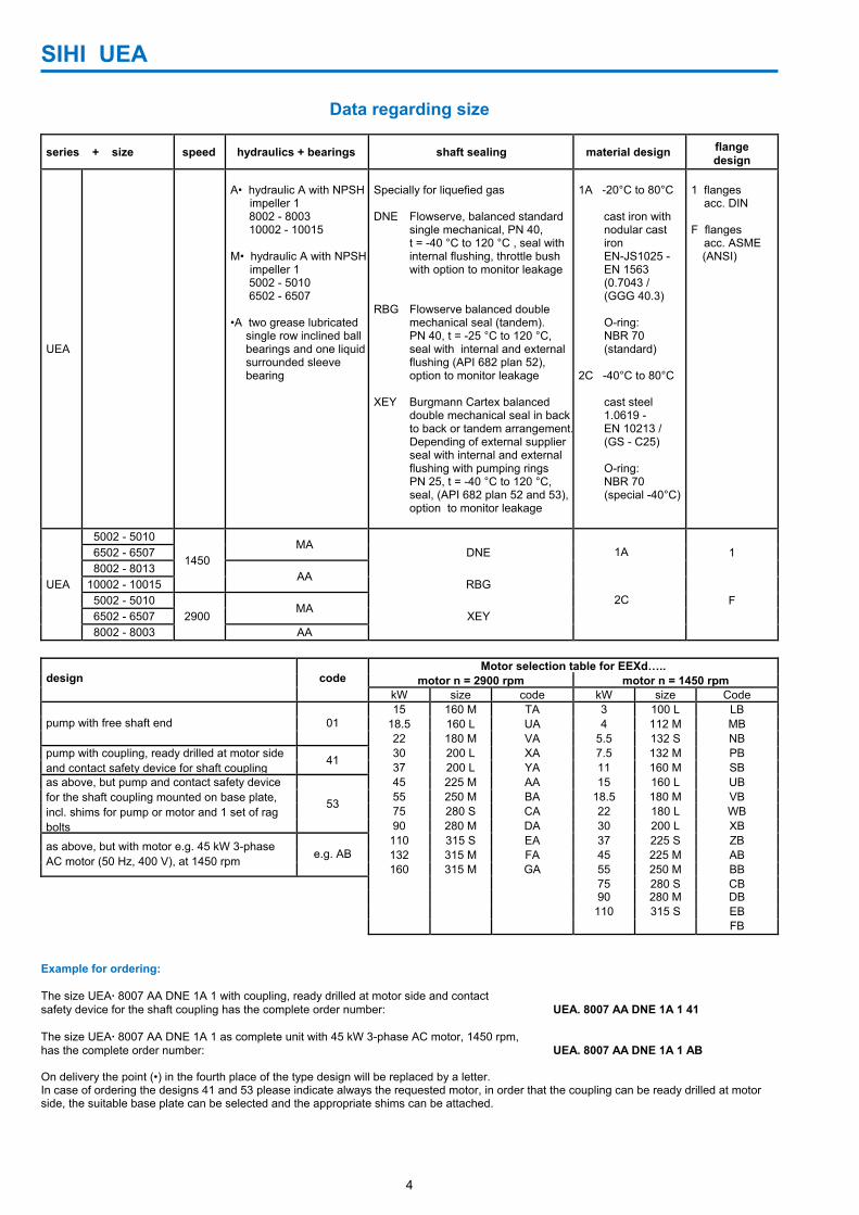
Data regarding size
series + size speed hydraulics + bearings shaft sealing material design flange design
UEA
A• hydraulic A with NPSH impeller 1
8002 - 8003 10002 - 10015
M• hydraulic A with NPSH impeller 1
5002 - 5010 6502 - 6507
•A two grease lubricated
single row inclined ball bearings and one liquidsurrounded sleeve bearing
Specially for liquefied gas DNE Flowserve, balanced standard single mechanical, PN 40, t = -40 °C to 120 °C , seal with internal flushing, throttle bush with option to monitor leakage
RBG Flowserve balanced double mechanical seal (tandem). PN 40, t = -25 °C to 120 °C, seal with internal and external flushing (API 682 plan 52), option to monitor leakage XEY Burgmann Cartex balanced double mechanical seal in back to back or tandem arrangement. Depending of external supplier seal with internal and external flushing with pumping rings PN 25, t = -40 °C to 120 °C, seal, (API 682 plan 52 and 53), option to monitor leakage
1A -20°C to 80°C
cast iron with nodular cast iron EN-JS1025 - EN 1563 (0.7043 / (GGG 40.3) O-ring: NBR 70 (standard)
2C -40°C to 80°C
cast steel 1.0619 - EN 10213 / (GS - C25)
O-ring: NBR 70
(special -40°C)
1 flanges acc. DIN F flanges acc. ASME
(ANSI)
UEA
5002 - 5010
1450 MA
6502 - 6507 DNE 1A 1 8002 - 8013
AA
10002 - 10015 RBG 5002 - 5010
2900 MA
2C F 6502 - 6507 XEY 8002 - 8003 AA
design code Motor selection table for EEXd…..
motor n = 2900 rpm motor n = 1450 rpmkW size code kW size Code
pump with free shaft end 01 15 160 M TA 3 100 L LB
18.5 160 L UA 4 112 M MB22 180 M VA 5.5 132 S NB
pump with coupling, ready drilled at motor side and contact safety device for shaft coupling
41 30 200 L XA 7.5 132 M PB37 200 L YA 11 160 M SB
as above, but pump and contact safety device for the shaft coupling mounted on base plate, incl. shims for pump or motor and 1 set of rag bolts
53
45 225 M AA 15 160 L UB55 250 M BA 18.5 180 M VB75 280 S CA 22 180 L WB90 280 M DA 30 200 L XB
as above, but with motor e.g. 45 kW 3-phase AC motor (50 Hz, 400 V), at 1450 rpm e.g. AB
110 315 S EA 37 225 S ZB132 315 M FA 45 225 M AB160 315 M GA 55 250 M BB
75 280 S CB 90 280 M DB 110 315 S EB FB
Example for ordering: The size UEA· 8007 AA DNE 1A 1 with coupling, ready drilled at motor side and contact safety device for the shaft coupling has the complete order number: UEA. 8007 AA DNE 1A 1 41 The size UEA· 8007 AA DNE 1A 1 as complete unit with 45 kW 3-phase AC motor, 1450 rpm, has the complete order number: UEA. 8007 AA DNE 1A 1 AB On delivery the point (•) in the fourth place of the type design will be replaced by a letter. In case of ordering the designs 41 and 53 please indicate always the requested motor, in order that the coupling can be ready drilled at motor side, the suitable base plate can be selected and the appropriate shims can be attached.
SIHI UEA
5
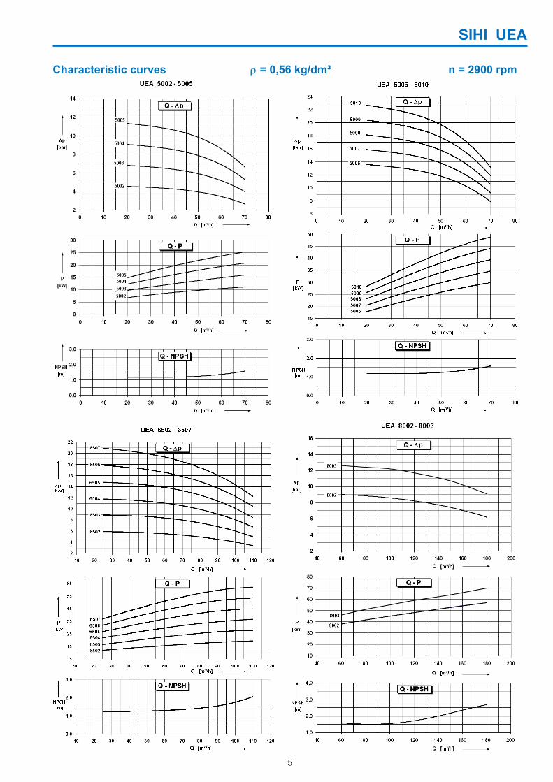
Characteristic curves ρ = 0,56 kg/dm³ n = 2900 rpm
SIHI UEA
6
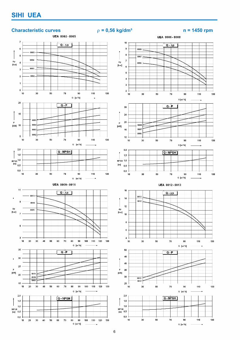
Characteristic curves ρ = 0,56 kg/dm³ n = 1450 rpm
SIHI UEA
7
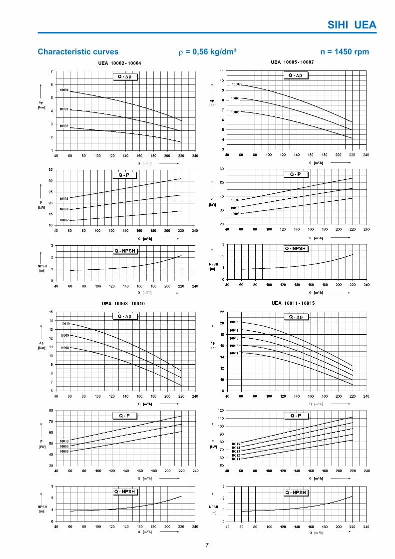
Characteristic curves ρ = 0,56 kg/dm³ n = 1450 rpm
SIHI UEA
8
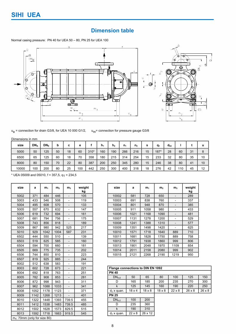
Dimension table Normal casing pressure: PN 40 for UEA 50 – 80, PN 25 for UEA 100
ue = connection for drain G3/8, for UEA 10 000 G1/2, um= connection for pressure gauge G3/8 Dimensions in mm
size DNA DNE b c e f h1 h2 n1 n2 s q1 dk6 l t u
5000 50 125 50 18 60 310* 160 190 266 216 15 187* 28 60 31 8
6500 65 125 60 18 70 358 180 215 314 254 15 233 32 80 35 10
8000 80 150 70 22 80 387 200 250 345 280 15 246 38 80 41 10
10000 100 200 80 25 100 442 250 300 400 318 18 276 42 110 45 12
* UEA 05009 and 05010, f = 357,5, q1 = 234,5
size a m1 m2 m3 weight kg
size a m1 m2 m3 weightkg
5002 371 484 446 - 105 10002 581 728 650 - 289 5003 433 546 508 - 119 10003 691 838 760 - 337 5004 495 608 570 - 133 10004 801 948 870 - 385 5005 557 670 632 - 147 10005 911 1058 980 - 433 5006 619 732 694 - 161 10006 1021 1168 1090 - 481 5007 681 794 756 - 175 10007 1131 1278 1200 - 529 5008 743 856 818 - 189 10008 1241 1388 1310 - 577 5009 867 980 942 525 217 10009 1351 1498 1420 - 625 5010 929 1042 1004 587 231 10010 1571 1718 1640 889 710 6502 444 550 510 - 139 10011 1681 1828 1750 889 758 6503 519 625 585 - 160 10012 1791 1938 1860 999 806 6504 594 700 660 - 181 10013 1901 2048 1970 1109 854 6505 669 775 735 - 202 10014 2011 2158 2080 999 902 6506 744 850 810 - 223 10015 2121 2268 2190 1219 950 6507 819 925 885 - 244 8002 512 638 583 - 191 8003 602 728 673 - 221 Flange connections to DIN EN 1092 8004 692 818 763 - 251 PN 40 8005 782 908 853 - 281 DNA,E 50 65 80 100 125 150 8006 872 998 943 - 311 D 165 185 200 235 270 300 8007 962 1088 1033 - 341 k 125 145 160 190 220 250 8008 1052 1178 1123 - 371 d2 x quan. 18 x 4 18 x 8 18 x 8 22 x 8 26 x 8 26 x 8 8009 1142 1268 1213 - 401 PN 25 8010 1322 1448 1393 739.5 455 DNA,E 100 200 8011 1412 1538 1483 739.5 485 D 235 360 8012 1502 1628 1573 829.5 515 k 190 310 8013 1592 1718 1663 919.5 545 d2 x quan. 22 x 8 26 x 12
m4: 70mm (only for size 80)
SIHI UEA
9
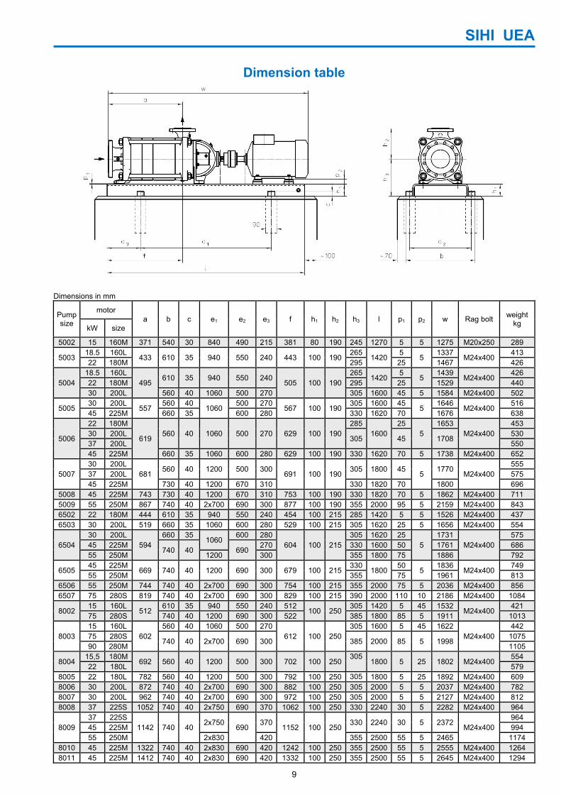
Dimension table
Dimensions in mm
Pump size
motor a b c e1 e2 e3 f h1 h2 h3 l p1 p2 w Rag bolt weight
kg kW size
5002 15 160M 371 540 30 840 490 215 381 80 190 245 1270 5 5 1275 M20x250 289
5003 18.5 160L
433 610 35 940 550 240 443 100 190265
14205
5 1337
M24x400 413
22 180M 295 25 1467 426
5004 18.5 160L
495 610 35 940 550 240
505 100 190265
14205
5 1439
M24x400 426
22 180M 295 25 1529 440 30 200L 560 40 1060 500 270 305 1600 45 5 1584 M24x400 502
5005 30 200L
557 560 40
1060 500 270
567 100 190305 1600 45
5 1646
M24x400 516
45 225M 660 35 600 280 330 1620 70 1676 638
5006
22 180M
619 560 40 1060 500 270 629 100 190
2851600
25 5
1653 M24x400
453 30 200L
305 45 1708 530
37 200L 550 45 225M 660 35 1060 600 280 629 100 190 330 1620 70 5 1738 M24x400 652
5007 30 200L
681 560 40 1200 500 300
691 100 190305 1800 45
5 1770
M24x400 555
37 200L 575 45 225M 730 40 1200 670 310 330 1820 70 1800 696
5008 45 225M 743 730 40 1200 670 310 753 100 190 330 1820 70 5 1862 M24x400 711 5009 55 250M 867 740 40 2x700 690 300 877 100 190 355 2000 95 5 2159 M24x400 843 6502 22 180M 444 610 35 940 550 240 454 100 215 285 1420 5 5 1526 M24x400 437 6503 30 200L 519 660 35 1060 600 280 529 100 215 305 1620 25 5 1656 M24x400 554
6504 30 200L
594 660 35
1060 600 280
604 100 215305 1620 25
5 1731
M24x400 575
45 225M 740 40 690
270 330 1600 50 1761 686 55 250M 1200 300 355 1800 75 1886 792
6505 45 225M
669 740 40 1200 690 300 679 100 215330
180050
5 1836
M24x400 749
55 250M 355 75 1961 813 6506 55 250M 744 740 40 2x700 690 300 754 100 215 355 2000 75 5 2036 M24x400 856 6507 75 280S 819 740 40 2x700 690 300 829 100 215 390 2000 110 10 2186 M24x400 1084
8002 15 160L
512 610 35 940 550 240 512
100 250305 1420 5 45 1532
M24x400 421
75 280S 740 40 1200 690 300 522 385 1800 85 5 1911 1013
8003 15 160L
602 560 40 1060 500 270
612 100 250305 1600 5 45 1622
M24x400 442
75 280S 740 40 2x700 690 300 385 2000 85 5 1998
1075 90 280M 1105
8004 15,5 180M
692 560 40 1200 500 300 702 100 250305
1800 5 25 1802 M24x400 554
22 180L 579 8005 22 180L 782 560 40 1200 500 300 792 100 250 305 1800 5 25 1892 M24x400 609 8006 30 200L 872 740 40 2x700 690 300 882 100 250 305 2000 5 5 2037 M24x400 782 8007 30 200L 962 740 40 2x700 690 300 972 100 250 305 2000 5 5 2127 M24x400 812 8008 37 225S 1052 740 40 2x750 690 370 1062 100 250 330 2240 30 5 2282 M24x400 964
8009 37 225S
1142 740 40 2x750
690 370
1152 100 250330 2240 30 5 2372
M24x400 964
45 225M 994 55 250M 2x830 420 355 2500 55 5 2465 1174
8010 45 225M 1322 740 40 2x830 690 420 1242 100 250 355 2500 55 5 2555 M24x400 1264 8011 45 225M 1412 740 40 2x830 690 420 1332 100 250 355 2500 55 5 2645 M24x400 1294
SIHI UEA
10
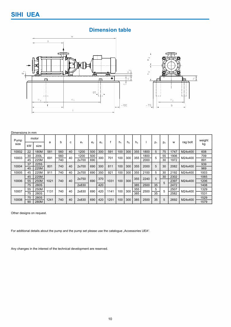
Dimension table
Dimensions in mm
Pump size
motor a b c e1 e2 e3 f h1 h2 h3 l p1 p2 w rag bolt weight
kg kW size
10002 22 180M 581 560 40 1200 500 300 591 100 300 355 1800 5 75 1747 M24x400 608
10003 30 200L
691 560
40 1200 500
300 701 100 300 3551800
5 55 1906
M24x400709
45 225M 740 2x700 690 2000 30 1972 891
10004 37 225S
801 740 40 2x700 690 300 811 100 300 355 2000 5 30 2082 M24x400939
45 225M 969 10005 45 225M 911 740 40 2x700 690 350 921 100 300 355 2100 5 30 2192 M24x400 1003
10006 45 225M
1021 740 40 2x750
690 370
1031 100 300355 2240 5
30 2302 M24x400
1065 55 250M
5 2397 1206
75 280S 2x830 420 385 2500 35 2472 1408
10007 55 250M
1131 740 40 2x830 690 420 1141 100 300355
2500 5
5 2507
M24x4001329
75 280S 385 35 2582 1531
10008 75 280S
1241 740 40 2x830 690 420 1251 100 300 385 2500 35 5 2692 M24x4001529
90 280M 1579 Other designs on request. For additional details about the pump and the pump set please use the catalogue „Accessories UEA“. Any changes in the interest of the technical development are reserved.

SIHI UEA
11
SIHI UEA
12
Sterling SIHI GmbH Works Ludwigshafen Halbergstr. 1, 67061 Ludwigshafen, Germany Tel. +49 (0) 621 56 12 - 0 Fax +49 (0) 621 56 12 - 209 www.sterlingSIHI.com