Embed Size (px)
Citation preview
Central Pollution Control Board
http://www.cpcbenvis.nic.in/newsletter/technologyoct1999/oct1999.htm[9/6/2012 11:02:24 AM]
InroductionIndustrial SectorChemical IndustriesAgro-based IndustriesMining IndustriesThermal Power PlantsReader's Column
Central Pollution Control Board
http://www.cpcbenvis.nic.in/newsletter/technologyoct1999/oct99edi.htm[9/6/2012 11:02:25 AM]
Contents
Archives
Home
Technology is a useful tool for providing goods and services to the modern day society. Yet,technology is often perceived as the cause of pollution and wanton exploitation of naturalendowments as experienced in the wake of industrialisation, urbanisation and motorisation.However, many of the problems which are attributed to technology can also be resolvedthrough proper application and upgradation of available technologies. This is particularlyevident in industrial activities which can reduce consumption of resources and minimisepollution, if not achieve "zero discharge", through technological innovations. In respect ofvarious industrial operations, pollution control technologies have been developed and usedwhile others need to adopt such technologies and look for newer technological interventions.To this end, industry, R & D institutions and regulatory bodies need to work in tandem.
In this issue of Parivesh, we present an overview of the available technologies andrequirements for pollution control in a cross section of industry. The information, collated bymy colleagues, is detailed in our technical publications entitled "Comprehensive IndustryDocuments Series (COINDS)".
We trust, dissemination of such information will promote awareness of pollutioncontrol requirements and stimulate initiatives for "Environmentally Sound Technologies(ESTs)".
Dilip Biswas Chairman,CPCB
Central Pollution Control Board
http://www.cpcbenvis.nic.in/newsletter/technologyoct1999/oct1999intro.htm[9/6/2012 11:02:26 AM]
Technologies for Pollution Control Industry
INTRODUCTIONS
The advent of the industrial revolution has irreversibly impacted on the way people across the globe live their daily lives.The process of industrialisation has left none untouched, in some way or the other, though in varying measure. While ithas influenced both, family and society, its impact on humankind's struggle against its environmental after-effects hasbeen most profound.
The larger environmental repercussions of our industrial age have to do with the pollution that accompanies it. Pollutionaccompanies every outshoot of industrialisation, be it industrial production, generation of electric power or vehiculartransport. It has also become a marked feature of the lifestyles that have come to mark the end of the twentieth century.
The varied sources and forms of pollution are only matched by the various technologies developed to control pollution,be it pollution generated from industries, vehicles, use of fuel in generation of power steam, liquid & solid wastesgenerated from municipal / residential areas. Indeed, the scientific community all over the world has been giving an extrathrust to researching and designing pollution control mechanisms.
The difference in pollution control technologies is obvious. Pollution control technologies in the industrial sector includemodification in processes, plant practices, in-plant control measures and end-on systems to remove pollutants (includingrecovery and reuse). On the other hand, the wastes generated from municipal/residential areas (mainly sewage, municipalsolid waste and bio-medical waste) have to be properly treated and disposed off. Of late, municipal wastes are alsoproviding for fuel gases or fertiliser pellets. Concurrently, the approach to controlling pollution from vehicles includesimproved fuel quality, improved engine design and control system (i.e. catalytic converter).
This edition of Parivesh deals with the pollution control technologies in practice in various industrial sectors and therequirements to meet the objective for maintaining the quality of air and water. For us at the Central Pollution ControlBoard (CPCB), this is also important as it falls well within our mandate of activities defined under the Air (Prevention &Control of Pollution) Act, 1981, and the Water (Prevention & Control of Pollution) Act, 1974.
Back to Content
Central Pollution Control Board
http://www.cpcbenvis.nic.in/newsletter/technologyoct1999/oct1999intro1.htm[9/6/2012 11:02:26 AM]
Technologies for Pollution Control Industry
Industrial Sector
In keeping with the functions delegated to the CPCB under the Air (Prevention & Control of Pollution) Act, 1981, andthe Water (Prevention & Control of Pollution) Act, 1974, CPCB undertook the national programme to control pollutionby initiating preparation of Comprehensive Industry Documents, categorising important industrial sectors. Thesedocuments were expected to provide comprehensive information on the industries. They covered a number of industries,their production and location with details on receiving water body besides details on the raw material they used, theprocess they adopted to process them, in-plant control systems, pollution control system provided and the futurerequirement with cost implications, monitoring system etc.
These documents are also aimed at developing standards for effluents and emissions as Minimal National Standards thatcan be adopted uniformly throughout the country. The State Pollution Control Boards (SPCBs) can tighten the standards,wherever the local situation demands.
While implementing these standards, the status of technologies adopted by the industries and further requirements tomeet the overall objective of pollution control have been assessed. The technology requirement for pollution controlindustry-wise has been presented in the following groups of industry categories:
Back to Content
Central Pollution Control Board
http://www.cpcbenvis.nic.in/newsletter/technologyoct1999/oct1999intro2.htm[9/6/2012 11:02:27 AM]
Technologies for Pollution Control Industry
CHEMICAL INDUSTRIES
Fertiliser Industry
The fertiliser industry occupies a place of pride in the chemical industries sector. This industry can be classified intothree categories, i.e. phosphatic fertiliser, nitrogenous fertiliser and complex fertiliser. The main pollutants from thephosphatic fertiliser plants are sulphur dioxide from the captive sulphuric acid plants and fluoride and particulate matterfrom the processing units (phosphate rock grinding, granulation & bagging sections). The scrubbing liquid for control ofgaseous emission results in the generation of wastewater. Besides, there may be some wastewater (spillage/washings)generated from sulphuric acid plant.
The existing pollution control systems in these sectors and the scope for making them more efficient are tabulated below:
Phosphatic Fertiliser Plant :
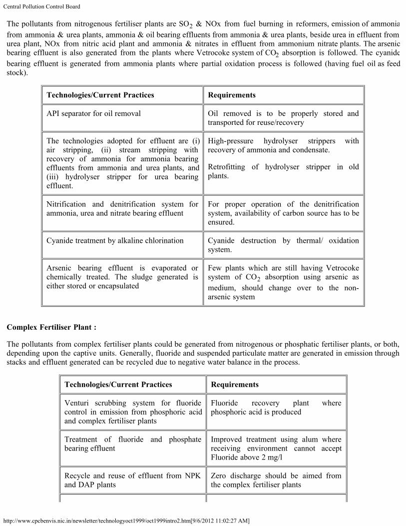
Technologies/Current Practices Requirements
The double conversion double absorption(DCDA) process has been recommended andadopted to minimise generation of SO2 fromsulphuric acid plants. Some plants havescrubbing system to control excessive SO2during start-up and shut-down of the plant.
Scrubbing systems with proper treatment forreuse / recovery of the scrubbing liquidshould be provided by all the plants.
Scrubbing system (two or three stages) orventuri scrubbing system has been adopted tocontrol fluoride emitted from acidulation ofrock phosphate
Venturi scrubbers with reuse/recovery ofscrubbing liquid or fluorine recovery plantneed to be provided
Bag filters and cyclones have been providedfor control of SPM.
Proper collection and disposal of collectedparticulate matter through cyclone, bagfilters etc. Pneumatic systems can be usedfor collection and transportation of dust inlarge plants.
Neutralisation for acidic wastewater and fluorideand phosphate removal through chemicalprecipitation for fluoride & phosphate bearingeffluent have been adopted.
Automatic feeding system for chemicaldosing with pH indicator and alarmsystem need to be installed.
Nitrogenous Fertiliser Plant :
Central Pollution Control Board
http://www.cpcbenvis.nic.in/newsletter/technologyoct1999/oct1999intro2.htm[9/6/2012 11:02:27 AM]
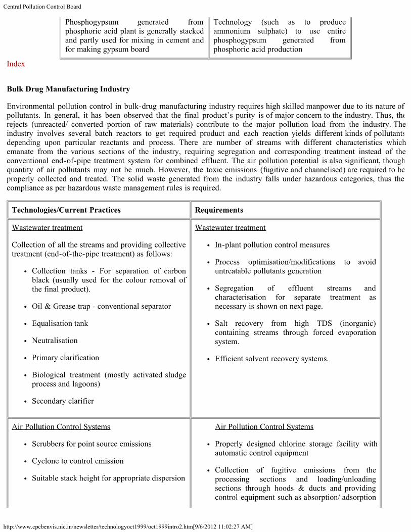
The pollutants from nitrogenous fertiliser plants are SO2 & NOx from fuel burning in reformers, emission of ammoniafrom ammonia & urea plants, ammonia & oil bearing effluents from ammonia & urea plants, beside urea in effluent fromurea plant, NOx from nitric acid plant and ammonia & nitrates in effluent from ammonium nitrate plants. The arsenicbearing effluent is also generated from the plants where Vetrocoke system of CO2 absorption is followed. The cyanidebearing effluent is generated from ammonia plants where partial oxidation process is followed (having fuel oil as feedstock).
Technologies/Current Practices Requirements
API separator for oil removal Oil removed is to be properly stored andtransported for reuse/recovery
The technologies adopted for effluent are (i)air stripping, (ii) stream stripping withrecovery of ammonia for ammonia bearingeffluents from ammonia and urea plants, and(iii) hydrolyser stripper for urea bearingeffluent.
High-pressure hydrolyser strippers withrecovery of ammonia and condensate.
Retrofitting of hydrolyser stripper in oldplants.
Nitrification and denitrification system forammonia, urea and nitrate bearing effluent
For proper operation of the denitrificationsystem, availability of carbon source has to beensured.
Cyanide treatment by alkaline chlorination Cyanide destruction by thermal/ oxidationsystem.
Arsenic bearing effluent is evaporated orchemically treated. The sludge generated iseither stored or encapsulated
Few plants which are still having Vetrocokesystem of CO2 absorption using arsenic asmedium, should change over to the non-arsenic system
Complex Fertiliser Plant :
The pollutants from complex fertiliser plants could be generated from nitrogenous or phosphatic fertiliser plants, or both,depending upon the captive units. Generally, fluoride and suspended particulate matter are generated in emission throughstacks and effluent generated can be recycled due to negative water balance in the process.
Technologies/Current Practices Requirements
Venturi scrubbing system for fluoridecontrol in emission from phosphoric acidand complex fertiliser plants
Fluoride recovery plant wherephosphoric acid is produced
Treatment of fluoride and phosphatebearing effluent
Improved treatment using alum wherereceiving environment cannot acceptFluoride above 2 mg/l
Recycle and reuse of effluent from NPKand DAP plants
Zero discharge should be aimed fromthe complex fertiliser plants
Central Pollution Control Board
http://www.cpcbenvis.nic.in/newsletter/technologyoct1999/oct1999intro2.htm[9/6/2012 11:02:27 AM]
Phosphogypsum generated fromphosphoric acid plant is generally stackedand partly used for mixing in cement andfor making gypsum board
Technology (such as to produceammonium sulphate) to use entirephosphogypsum generated fromphosphoric acid production
Index
Bulk Drug Manufacturing Industry
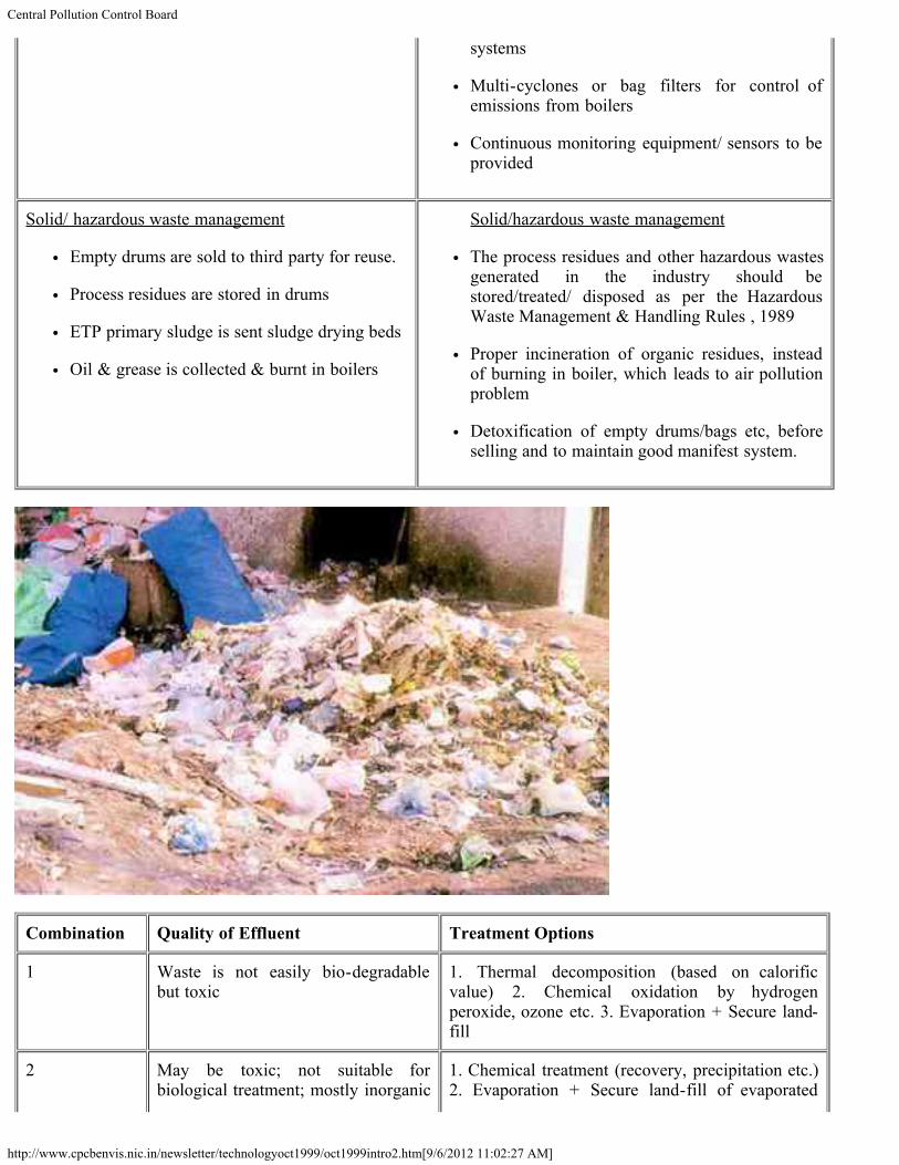
Environmental pollution control in bulk-drug manufacturing industry requires high skilled manpower due to its nature ofpollutants. In general, it has been observed that the final product’s purity is of major concern to the industry. Thus, therejects (unreacted/ converted portion of raw materials) contribute to the major pollution load from the industry. Theindustry involves several batch reactors to get required product and each reaction yields different kinds of pollutantsdepending upon particular reactants and process. There are number of streams with different characteristics whichemanate from the various sections of the industry, requiring segregation and corresponding treatment instead of theconventional end-of-pipe treatment system for combined effluent. The air pollution potential is also significant, thoughquantity of air pollutants may not be much. However, the toxic emissions (fugitive and channelised) are required to beproperly collected and treated. The solid waste generated from the industry falls under hazardous categories, thus thecompliance as per hazardous waste management rules is required.
Technologies/Current Practices Requirements
Wastewater treatment
Collection of all the streams and providing collectivetreatment (end-of-the-pipe treatment) as follows:
Collection tanks - For separation of carbonblack (usually used for the colour removal ofthe final product).
Oil & Grease trap - conventional separator
Equalisation tank
Neutralisation
Primary clarification
Biological treatment (mostly activated sludgeprocess and lagoons)
Secondary clarifier
Wastewater treatment
In-plant pollution control measures
Process optimisation/modifications to avoiduntreatable pollutants generation
Segregation of effluent streams andcharacterisation for separate treatment asnecessary is shown on next page.
Salt recovery from high TDS (inorganic)containing streams through forced evaporationsystem.
Efficient solvent recovery systems.
Air Pollution Control Systems
Scrubbers for point source emissions
Cyclone to control emission
Suitable stack height for appropriate dispersion
Air Pollution Control Systems
Properly designed chlorine storage facility withautomatic control equipment
Collection of fugitive emissions from theprocessing sections and loading/unloadingsections through hoods & ducts and providingcontrol equipment such as absorption/ adsorption
Central Pollution Control Board
http://www.cpcbenvis.nic.in/newsletter/technologyoct1999/oct1999intro2.htm[9/6/2012 11:02:27 AM]
systems
Multi-cyclones or bag filters for control ofemissions from boilers
Continuous monitoring equipment/ sensors to beprovided
Solid/ hazardous waste management
Empty drums are sold to third party for reuse.
Process residues are stored in drums
ETP primary sludge is sent sludge drying beds
Oil & grease is collected & burnt in boilers
Solid/hazardous waste management
The process residues and other hazardous wastesgenerated in the industry should bestored/treated/ disposed as per the HazardousWaste Management & Handling Rules , 1989
Proper incineration of organic residues, insteadof burning in boiler, which leads to air pollutionproblem
Detoxification of empty drums/bags etc, beforeselling and to maintain good manifest system.
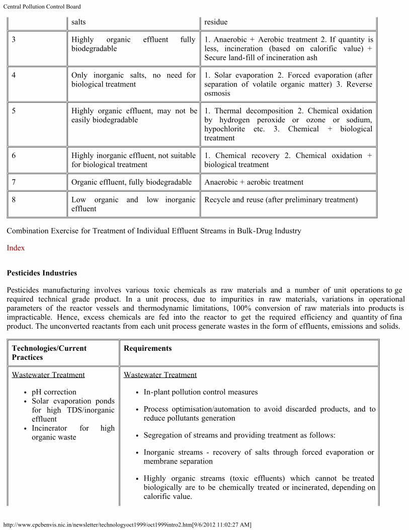
Combination Quality of Effluent Treatment Options
1 Waste is not easily bio-degradablebut toxic
1. Thermal decomposition (based on calorificvalue) 2. Chemical oxidation by hydrogenperoxide, ozone etc. 3. Evaporation + Secure land-fill
2 May be toxic; not suitable forbiological treatment; mostly inorganic
1. Chemical treatment (recovery, precipitation etc.)2. Evaporation + Secure land-fill of evaporated
Central Pollution Control Board
http://www.cpcbenvis.nic.in/newsletter/technologyoct1999/oct1999intro2.htm[9/6/2012 11:02:27 AM]
salts residue
3 Highly organic effluent fullybiodegradable
1. Anaerobic + Aerobic treatment 2. If quantity isless, incineration (based on calorific value) +Secure land-fill of incineration ash
4 Only inorganic salts, no need forbiological treatment
1. Solar evaporation 2. Forced evaporation (afterseparation of volatile organic matter) 3. Reverseosmosis
5 Highly organic effluent, may not beeasily biodegradable
1. Thermal decomposition 2. Chemical oxidationby hydrogen peroxide or ozone or sodium,hypochlorite etc. 3. Chemical + biologicaltreatment
6 Highly inorganic effluent, not suitablefor biological treatment
1. Chemical recovery 2. Chemical oxidation +biological treatment
7 Organic effluent, fully biodegradable Anaerobic + aerobic treatment
8 Low organic and low inorganiceffluent
Recycle and reuse (after preliminary treatment)
Combination Exercise for Treatment of Individual Effluent Streams in Bulk-Drug Industry
Index
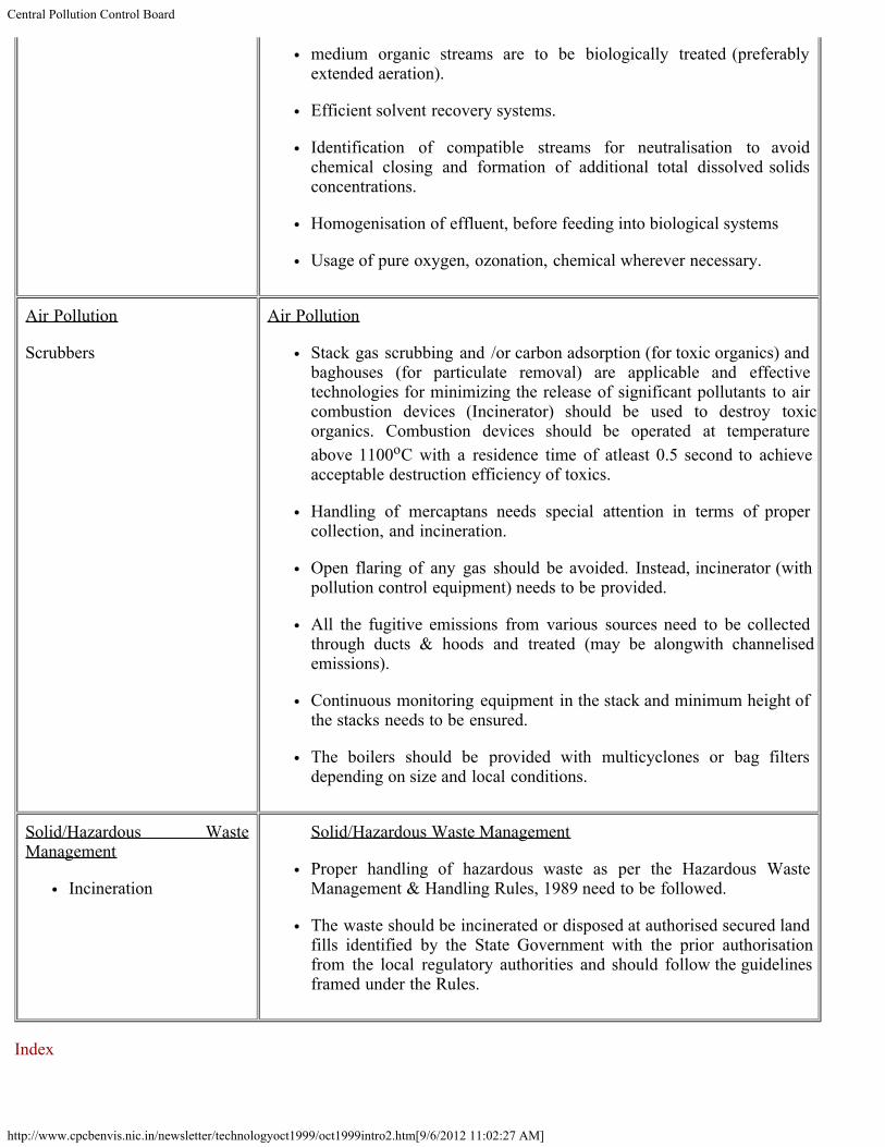
Pesticides Industries
Pesticides manufacturing involves various toxic chemicals as raw materials and a number of unit operations to getrequired technical grade product. In a unit process, due to impurities in raw materials, variations in operationalparameters of the reactor vessels and thermodynamic limitations, 100% conversion of raw materials into products isimpracticable. Hence, excess chemicals are fed into the reactor to get the required efficiency and quantity of finalproduct. The unconverted reactants from each unit process generate wastes in the form of effluents, emissions and solids.
Technologies/CurrentPractices
Requirements
Wastewater Treatment
pH correctionSolar evaporation pondsfor high TDS/inorganiceffluentIncinerator for highorganic waste
Wastewater Treatment
In-plant pollution control measures
Process optimisation/automation to avoid discarded products, and toreduce pollutants generation
Segregation of streams and providing treatment as follows:
Inorganic streams - recovery of salts through forced evaporation ormembrane separation
Highly organic streams (toxic effluents) which cannot be treatedbiologically are to be chemically treated or incinerated, depending oncalorific value.
Central Pollution Control Board
http://www.cpcbenvis.nic.in/newsletter/technologyoct1999/oct1999intro2.htm[9/6/2012 11:02:27 AM]
medium organic streams are to be biologically treated (preferablyextended aeration).
Efficient solvent recovery systems.
Identification of compatible streams for neutralisation to avoidchemical closing and formation of additional total dissolved solidsconcentrations.
Homogenisation of effluent, before feeding into biological systems
Usage of pure oxygen, ozonation, chemical wherever necessary.
Air Pollution
Scrubbers
Air Pollution
Stack gas scrubbing and /or carbon adsorption (for toxic organics) andbaghouses (for particulate removal) are applicable and effectivetechnologies for minimizing the release of significant pollutants to aircombustion devices (Incinerator) should be used to destroy toxicorganics. Combustion devices should be operated at temperatureabove 1100oC with a residence time of atleast 0.5 second to achieveacceptable destruction efficiency of toxics.
Handling of mercaptans needs special attention in terms of propercollection, and incineration.
Open flaring of any gas should be avoided. Instead, incinerator (withpollution control equipment) needs to be provided.
All the fugitive emissions from various sources need to be collectedthrough ducts & hoods and treated (may be alongwith channelisedemissions).
Continuous monitoring equipment in the stack and minimum height ofthe stacks needs to be ensured.
The boilers should be provided with multicyclones or bag filtersdepending on size and local conditions.
Solid/Hazardous WasteManagement
Incineration
Solid/Hazardous Waste Management
Proper handling of hazardous waste as per the Hazardous WasteManagement & Handling Rules, 1989 need to be followed.
The waste should be incinerated or disposed at authorised secured landfills identified by the State Government with the prior authorisationfrom the local regulatory authorities and should follow the guidelinesframed under the Rules.
Index
Central Pollution Control Board
http://www.cpcbenvis.nic.in/newsletter/technologyoct1999/oct1999intro2.htm[9/6/2012 11:02:27 AM]
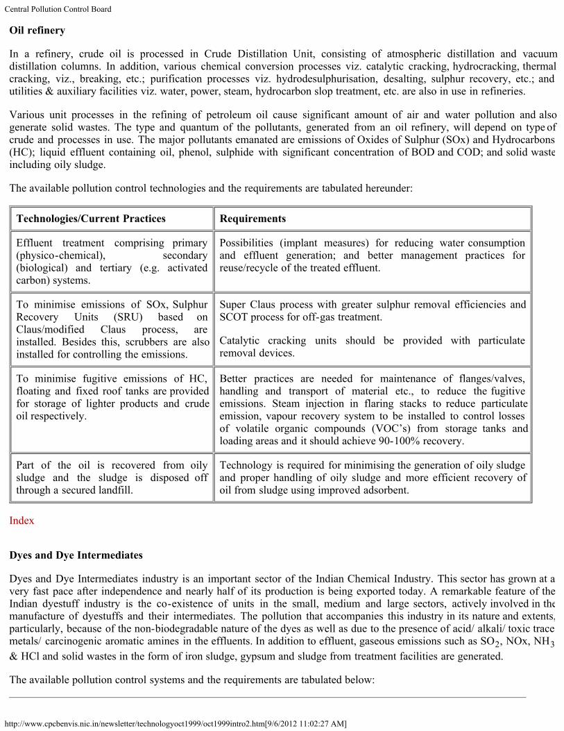
Oil refinery
In a refinery, crude oil is processed in Crude Distillation Unit, consisting of atmospheric distillation and vacuumdistillation columns. In addition, various chemical conversion processes viz. catalytic cracking, hydrocracking, thermalcracking, viz., breaking, etc.; purification processes viz. hydrodesulphurisation, desalting, sulphur recovery, etc.; andutilities & auxiliary facilities viz. water, power, steam, hydrocarbon slop treatment, etc. are also in use in refineries.
Various unit processes in the refining of petroleum oil cause significant amount of air and water pollution and alsogenerate solid wastes. The type and quantum of the pollutants, generated from an oil refinery, will depend on type ofcrude and processes in use. The major pollutants emanated are emissions of Oxides of Sulphur (SOx) and Hydrocarbons(HC); liquid effluent containing oil, phenol, sulphide with significant concentration of BOD and COD; and solid wasteincluding oily sludge.
The available pollution control technologies and the requirements are tabulated hereunder:
Technologies/Current Practices Requirements
Effluent treatment comprising primary(physico-chemical), secondary(biological) and tertiary (e.g. activatedcarbon) systems.
Possibilities (implant measures) for reducing water consumptionand effluent generation; and better management practices forreuse/recycle of the treated effluent.
To minimise emissions of SOx, SulphurRecovery Units (SRU) based onClaus/modified Claus process, areinstalled. Besides this, scrubbers are alsoinstalled for controlling the emissions.
Super Claus process with greater sulphur removal efficiencies andSCOT process for off-gas treatment.
Catalytic cracking units should be provided with particulateremoval devices.
To minimise fugitive emissions of HC,floating and fixed roof tanks are providedfor storage of lighter products and crudeoil respectively.
Better practices are needed for maintenance of flanges/valves,handling and transport of material etc., to reduce the fugitiveemissions. Steam injection in flaring stacks to reduce particulateemission, vapour recovery system to be installed to control lossesof volatile organic compounds (VOC’s) from storage tanks andloading areas and it should achieve 90-100% recovery.
Part of the oil is recovered from oilysludge and the sludge is disposed offthrough a secured landfill.
Technology is required for minimising the generation of oily sludgeand proper handling of oily sludge and more efficient recovery ofoil from sludge using improved adsorbent.
Index
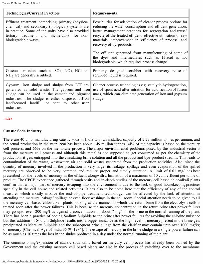
Dyes and Dye Intermediates
Dyes and Dye Intermediates industry is an important sector of the Indian Chemical Industry. This sector has grown at avery fast pace after independence and nearly half of its production is being exported today. A remarkable feature of theIndian dyestuff industry is the co-existence of units in the small, medium and large sectors, actively involved in themanufacture of dyestuffs and their intermediates. The pollution that accompanies this industry in its nature and extents,particularly, because of the non-biodegradable nature of the dyes as well as due to the presence of acid/ alkali/ toxic tracemetals/ carcinogenic aromatic amines in the effluents. In addition to effluent, gaseous emissions such as SO2, NOx, NH3& HCl and solid wastes in the form of iron sludge, gypsum and sludge from treatment facilities are generated.
The available pollution control systems and the requirements are tabulated below:
Central Pollution Control Board
http://www.cpcbenvis.nic.in/newsletter/technologyoct1999/oct1999intro2.htm[9/6/2012 11:02:27 AM]
Technologies/Current Practices Requirements
Effluent treatment comprising primary (physico-chemical) and secondary (biological) systems arein practice. Some of the units have also providedtertiary treatment and incinerators for non-biodegradable waste.
Possibilities for adaptation of cleaner process options forreducing the water consumption and effluent generation;better management practices for segregation and reuse/recycle of the treated effluent; effective utilisation of rawmaterials; improvement in efficiency of process; andrecovery of by-products.
The effluent generated from manufacturing of some ofthe dyes and intermediates such as H-acid is notbiodegradable, which requires process change.
Gaseous emissions such as SOx, NOx, HCl andNH3 are generally scrubbed.
Properly designed scrubber with recovery reuse ofscrubbed liquid is required.
Gypsum, iron sludge and sludge from ETP aregenerated as solid waste. The gypsum and ironsludge can be used in the cement and pigmentindustries. The sludge is either disposed off onland/secured landfill or sent to other userindustries.
Cleaner process technologies e.g. catalytic hydrogenation,use of spent acid after nitration for acidification of fusionmass, which can eliminate generation of iron and gypsumsludge.
Index
Caustic Soda Industry
There are 40 units manufacturing caustic soda in India with an installed capacity of 2.27 million tonnes per annum, andthe actual production in the year 1998 has been about 1.49 million tonnes. 34% of the capacity is based on the mercurycell process, and 66% on the membrane process. The major environmental problems posed by this industrial sector isfrom the mercury cell process and although this metal is not supposed to get consumed as per the chemistry of theproduction, it gets entrapped into the circulating brine solution and all the product and bye-product streams. This leads tocontamination of the water, wastewater, air and solid wastes generated from the production activities. Also, since thequantity of mercury involved in the production is very large, its leakage, spillage and even evaporation of the spilledmercury are observed to be very common and require proper and timely attention. A limit of 0.01 mg/l has beenprescribed for the levels of mercury in the effluent alongwith a limitation of a maximum of 10 cum effluent per tonne ofproduct. The CPCB experience gathered through visits and in-depth studies of the mercury cell based chlor-alkali plantsconfirm that a major part of mercury escaping into the environment is due to the lack of good housekeeping practicesspecially in the cell house and related activities. It has also to be noted here that the efficiency of any of the controlmeasures which mostly involve the end-of-pipe treatment technology, can be affected by the lack of attention inattending the mercury leakage/ spillage or even floor washings in the cell room. Special attention needs to be given to allthe mercury cell-based chlor-alkali plants looking at the manner in which the return brine from the electrolysis cells istreated soon after the power failures. This is because the mercury concentration in the return brine after power failuresmay go upto even 200 mg/l as against a concentration of about 7 mg/l in the brine in the normal running of the plant.There has been a practice of adding Sodium Sulphide to the brine after power failures for avoiding the chlorine nuisancebut this addition of Sodium Sulphide results into a bigger nuisance as the high level of mercury present in the brine getsprecipitated as Mercury Sulphide and the subsequent brine sludge from the clarifier may contain upto over 1000 mg/kgof mercury [Chemical Age of India 35 (9):1984]. The escape of mercury in the brine sludge in a single power failure canbe as much as 10 times the loss in the sludge produced in a day under the normal running of the plant.
The commissioning/expansion of caustic soda units based on mercury cell process has already been banned by theGovernment and the existing mercury cell based plants are also in the process of switching over to the membrane
Central Pollution Control Board
http://www.cpcbenvis.nic.in/newsletter/technologyoct1999/oct1999intro2.htm[9/6/2012 11:02:27 AM]
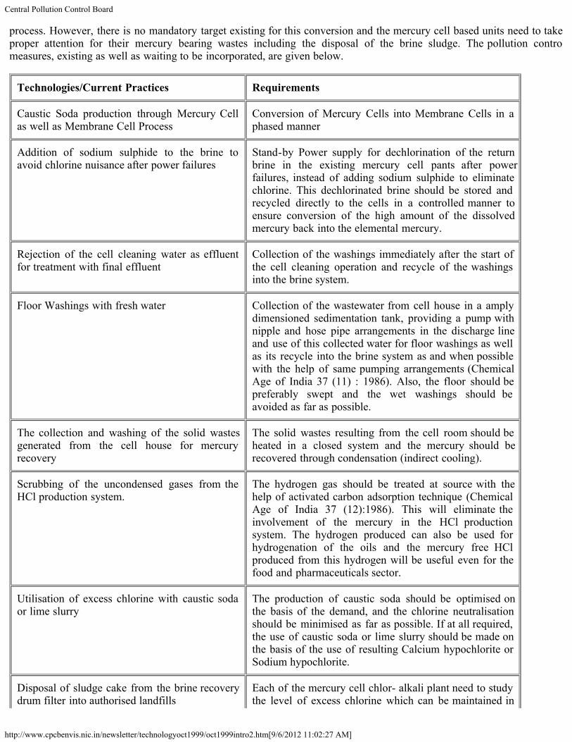
process. However, there is no mandatory target existing for this conversion and the mercury cell based units need to takeproper attention for their mercury bearing wastes including the disposal of the brine sludge. The pollution controlmeasures, existing as well as waiting to be incorporated, are given below.
Technologies/Current Practices Requirements
Caustic Soda production through Mercury Cellas well as Membrane Cell Process
Conversion of Mercury Cells into Membrane Cells in aphased manner
Addition of sodium sulphide to the brine toavoid chlorine nuisance after power failures
Stand-by Power supply for dechlorination of the returnbrine in the existing mercury cell pants after powerfailures, instead of adding sodium sulphide to eliminatechlorine. This dechlorinated brine should be stored andrecycled directly to the cells in a controlled manner toensure conversion of the high amount of the dissolvedmercury back into the elemental mercury.
Rejection of the cell cleaning water as effluentfor treatment with final effluent
Collection of the washings immediately after the start ofthe cell cleaning operation and recycle of the washingsinto the brine system.
Floor Washings with fresh water Collection of the wastewater from cell house in a amplydimensioned sedimentation tank, providing a pump withnipple and hose pipe arrangements in the discharge lineand use of this collected water for floor washings as wellas its recycle into the brine system as and when possiblewith the help of same pumping arrangements (ChemicalAge of India 37 (11) : 1986). Also, the floor should bepreferably swept and the wet washings should beavoided as far as possible.
The collection and washing of the solid wastesgenerated from the cell house for mercuryrecovery
The solid wastes resulting from the cell room should beheated in a closed system and the mercury should berecovered through condensation (indirect cooling).
Scrubbing of the uncondensed gases from theHCl production system.
The hydrogen gas should be treated at source with thehelp of activated carbon adsorption technique (ChemicalAge of India 37 (12):1986). This will eliminate theinvolvement of the mercury in the HCl productionsystem. The hydrogen produced can also be used forhydrogenation of the oils and the mercury free HClproduced from this hydrogen will be useful even for thefood and pharmaceuticals sector.
Utilisation of excess chlorine with caustic sodaor lime slurry
The production of caustic soda should be optimised onthe basis of the demand, and the chlorine neutralisationshould be minimised as far as possible. If at all required,the use of caustic soda or lime slurry should be made onthe basis of the use of resulting Calcium hypochlorite orSodium hypochlorite.
Disposal of sludge cake from the brine recoverydrum filter into authorised landfills
Each of the mercury cell chlor- alkali plant need to studythe level of excess chlorine which can be maintained in

Central Pollution Control Board
http://www.cpcbenvis.nic.in/newsletter/technologyoct1999/oct1999intro2.htm[9/6/2012 11:02:27 AM]
the circulating brine of the production system as thepresence of chlorine in brine avoids precipitation ofmercury into the brine sludge. Also, the disposal of brinesludge should be made in a secured landfill with properarrangements for the collection and recycle of theleachate.
Sodium sulphide precipitation, filtrationfollowed by ion exchange or activated carbonadsorption method of the mercury from the finaleffluent
The mercury bearing streams should be segregated at thesource itself in the plant and recycled into the brinesystem. This will result into minimisation of mercuryinput load to the final treatment system, and the stepslike precipitation, ion exchange etc. can be decided byindividual plants depending upon the level of mercurycontrol that can be achieved at source.
Back to Content
Central Pollution Control Board
http://www.cpcbenvis.nic.in/newsletter/technologyoct1999/oct1999intro3.htm[9/6/2012 11:02:28 AM]
Technologies for Pollution Control Industry
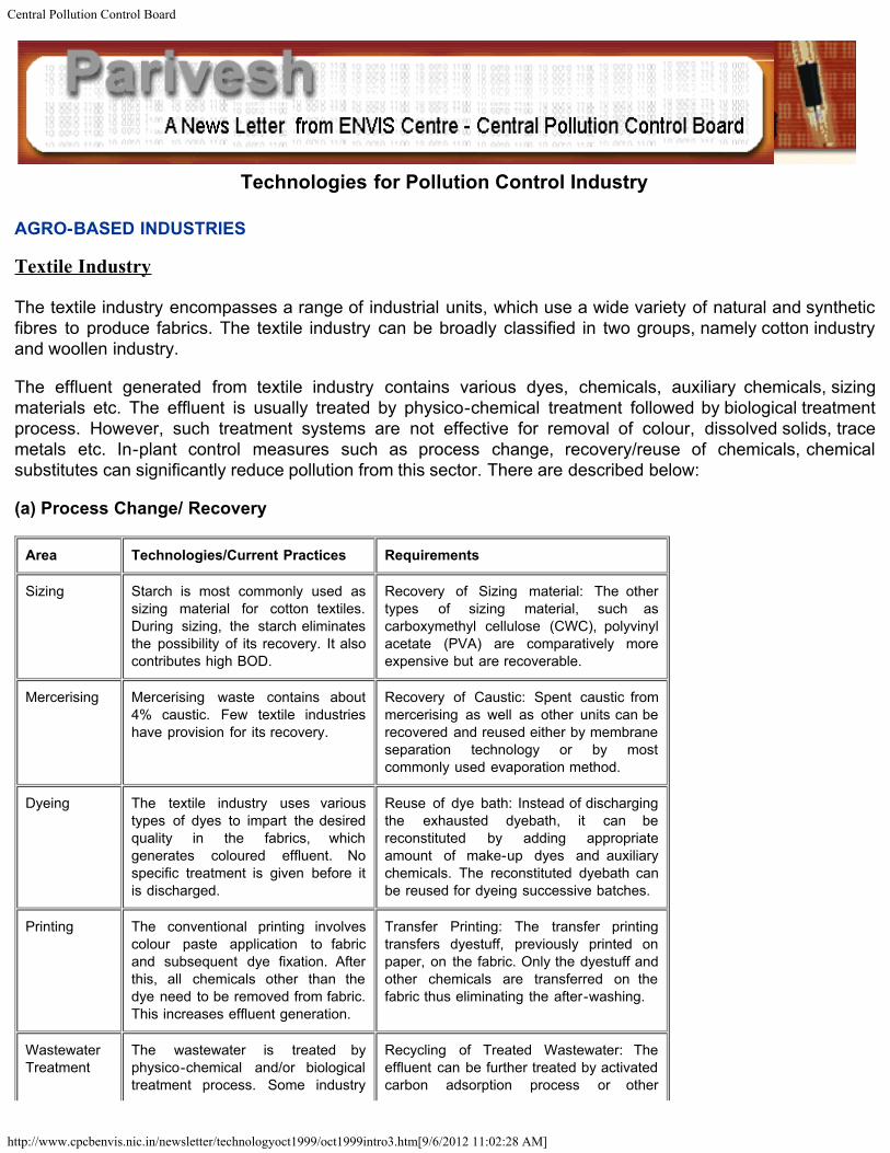
AGRO-BASED INDUSTRIES
Textile Industry
The textile industry encompasses a range of industrial units, which use a wide variety of natural and syntheticfibres to produce fabrics. The textile industry can be broadly classified in two groups, namely cotton industryand woollen industry.
The effluent generated from textile industry contains various dyes, chemicals, auxiliary chemicals, sizingmaterials etc. The effluent is usually treated by physico-chemical treatment followed by biological treatmentprocess. However, such treatment systems are not effective for removal of colour, dissolved solids, tracemetals etc. In-plant control measures such as process change, recovery/reuse of chemicals, chemicalsubstitutes can significantly reduce pollution from this sector. There are described below:
(a) Process Change/ Recovery
Area Technologies/Current Practices Requirements
Sizing Starch is most commonly used assizing material for cotton textiles.During sizing, the starch eliminatesthe possibility of its recovery. It alsocontributes high BOD.
Recovery of Sizing material: The othertypes of sizing material, such ascarboxymethyl cellulose (CWC), polyvinylacetate (PVA) are comparatively moreexpensive but are recoverable.
Mercerising Mercerising waste contains about4% caustic. Few textile industrieshave provision for its recovery.
Recovery of Caustic: Spent caustic frommercerising as well as other units can berecovered and reused either by membraneseparation technology or by mostcommonly used evaporation method.
Dyeing The textile industry uses varioustypes of dyes to impart the desiredquality in the fabrics, whichgenerates coloured effluent. Nospecific treatment is given before itis discharged.
Reuse of dye bath: Instead of dischargingthe exhausted dyebath, it can bereconstituted by adding appropriateamount of make-up dyes and auxiliarychemicals. The reconstituted dyebath canbe reused for dyeing successive batches.
Printing The conventional printing involvescolour paste application to fabricand subsequent dye fixation. Afterthis, all chemicals other than thedye need to be removed from fabric.This increases effluent generation.
Transfer Printing: The transfer printingtransfers dyestuff, previously printed onpaper, on the fabric. Only the dyestuff andother chemicals are transferred on thefabric thus eliminating the after-washing.
WastewaterTreatment
The wastewater is treated byphysico-chemical and/or biologicaltreatment process. Some industry
Recycling of Treated Wastewater: Theeffluent can be further treated by activatedcarbon adsorption process or other

Central Pollution Control Board
http://www.cpcbenvis.nic.in/newsletter/technologyoct1999/oct1999intro3.htm[9/6/2012 11:02:28 AM]
uses filtration alongwith physico-chemical treatment to reuse thespecific effluent streams.
advanced treatment process so that thetreated effluent can be recycled/reused.
(b) Chemical substitute
Area/Process Chemical in Use Substitute Required
Sizing/Process Conventional Starch basedsize
Synthetic wrap sizes (PVA)Acrylates)
Desizing Enzymes Acids
Soaping Conventional Soap Synthetic Detergents
Good Scouring Soda Ash Sodium Acetate
DisperseDyeing &PigmentPrinting
Acetic Acid Ammonium Sulphate
Printing Gum Emulsion
Oxidation of vatdye
Acetic Acid Sodium Bicarbonate
Screen Printingmachines
Conventional Gums Permanent Adhesives
Finishing starchbased
Temporary Finishes Durable Finishes
Dyeing Two stages dye (Disperse, vat.etc.)
Single stage dyes(Tindigosol)
Dyeing Solvent Pthalogen blue All aqueous Pthalogen blue
Dacron Dyeing Conventional Carriers Monochlorobenzene
Dye bath Acetic acid Formic Acid
Lubricants usedin textilemachinery
Carding oils anti-state lube Non-ionic emulsifiers
Index
Tanneries
Tanning is an integral part of leather making process, which converts the raw hides and skins to finished
Central Pollution Control Board
http://www.cpcbenvis.nic.in/newsletter/technologyoct1999/oct1999intro3.htm[9/6/2012 11:02:28 AM]
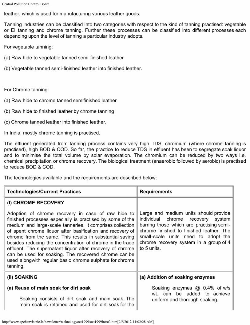
leather, which is used for manufacturing various leather goods.
Tanning industries can be classified into two categories with respect to the kind of tanning practised: vegetableor EI tanning and chrome tanning. Further these processes can be classified into different processes eachdepending upon the level of tanning a particular industry adopts.
For vegetable tanning:
(a) Raw hide to vegetable tanned semi-finished leather
(b) Vegetable tanned semi-finished leather into finished leather.
For Chrome tanning:
(a) Raw hide to chrome tanned semifinished leather
(b) Raw hide to finished leather by chrome tanning
(c) Chrome tanned leather into finished leather.
In India, mostly chrome tanning is practised.
The effluent generated from tanning process contains very high TDS, chromium (where chrome tanning ispractised), high BOD & COD. So far, the practice to reduce TDS in effluent has been to segregate soak liquorand to minimise the total volume by solar evaporation. The chromium can be reduced by two ways i.e.chemical precipitation or chrome recovery. The biological treatment (anaerobic followed by aerobic) is practisedto reduce BOD & COD.
The technologies available and the requirements are described below:
Technologies/Current Practices Requirements
(I) CHROME RECOVERY
Adoption of chrome recovery in case of raw hide tofinished processes especially is practised by some of themedium and large-scale tanneries. It comprises collectionof spent chrome liquor after basification and recovery ofchrome from the same. This results in substantial savingbesides reducing the concentration of chrome in the tradeeffluent. The supernatant liquor after recovery of chromecan be used for soaking. The recovered chrome can beused alongwith regular basic chrome sulphate for chrometanning.
Large and medium units should provideindividual chrome recovery systembarring those which are practising semi-chrome finished to finished leather. Thesmall-scale units need to adopt thechrome recovery system in a group of 4to 5 units.
(ii) SOAKING
(a) Reuse of main soak for dirt soak
Soaking consists of dirt soak and main soak. Themain soak is retained and used for dirt soak for the
(a) Addition of soaking enzymes
Soaking enzymes @ 0.4% of w/swt. can be added to achieveuniform and thorough soaking.
Central Pollution Control Board
http://www.cpcbenvis.nic.in/newsletter/technologyoct1999/oct1999intro3.htm[9/6/2012 11:02:28 AM]
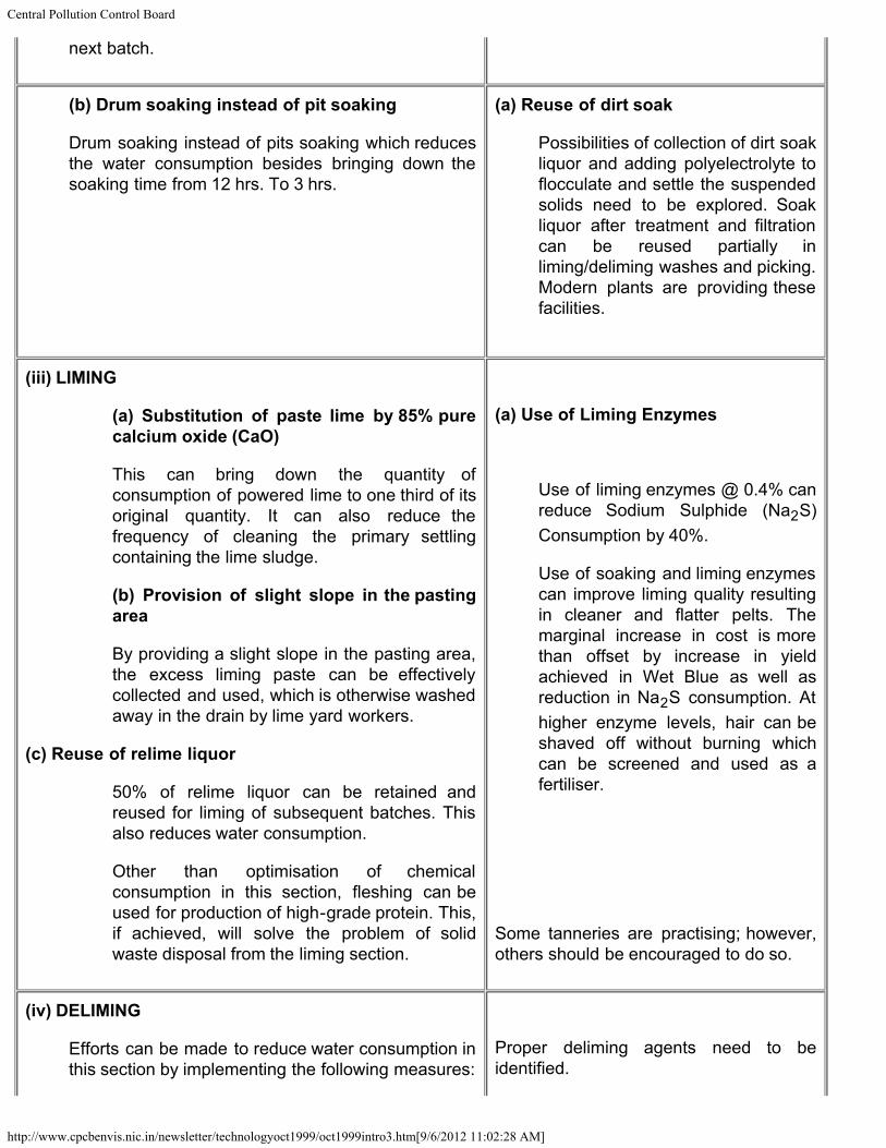
next batch.
(b) Drum soaking instead of pit soaking
Drum soaking instead of pits soaking which reducesthe water consumption besides bringing down thesoaking time from 12 hrs. To 3 hrs.
(a) Reuse of dirt soak
Possibilities of collection of dirt soakliquor and adding polyelectrolyte toflocculate and settle the suspendedsolids need to be explored. Soakliquor after treatment and filtrationcan be reused partially inliming/deliming washes and picking.Modern plants are providing thesefacilities.
(iii) LIMING
(a) Substitution of paste lime by 85% purecalcium oxide (CaO)
This can bring down the quantity ofconsumption of powered lime to one third of itsoriginal quantity. It can also reduce thefrequency of cleaning the primary settlingcontaining the lime sludge.
(b) Provision of slight slope in the pastingarea
By providing a slight slope in the pasting area,the excess liming paste can be effectivelycollected and used, which is otherwise washedaway in the drain by lime yard workers.
(c) Reuse of relime liquor
50% of relime liquor can be retained andreused for liming of subsequent batches. Thisalso reduces water consumption.
Other than optimisation of chemicalconsumption in this section, fleshing can beused for production of high-grade protein. This,if achieved, will solve the problem of solidwaste disposal from the liming section.
(a) Use of Liming Enzymes
Use of liming enzymes @ 0.4% canreduce Sodium Sulphide (Na2S)Consumption by 40%.
Use of soaking and liming enzymescan improve liming quality resultingin cleaner and flatter pelts. Themarginal increase in cost is morethan offset by increase in yieldachieved in Wet Blue as well asreduction in Na2S consumption. Athigher enzyme levels, hair can beshaved off without burning whichcan be screened and used as afertiliser.
Some tanneries are practising; however,others should be encouraged to do so.
(iv) DELIMING
Efforts can be made to reduce water consumption inthis section by implementing the following measures:
Proper deliming agents need to beidentified.
Central Pollution Control Board
http://www.cpcbenvis.nic.in/newsletter/technologyoct1999/oct1999intro3.htm[9/6/2012 11:02:28 AM]
a. Use of deliming agents.
b. Use of first delimes wash for liming.
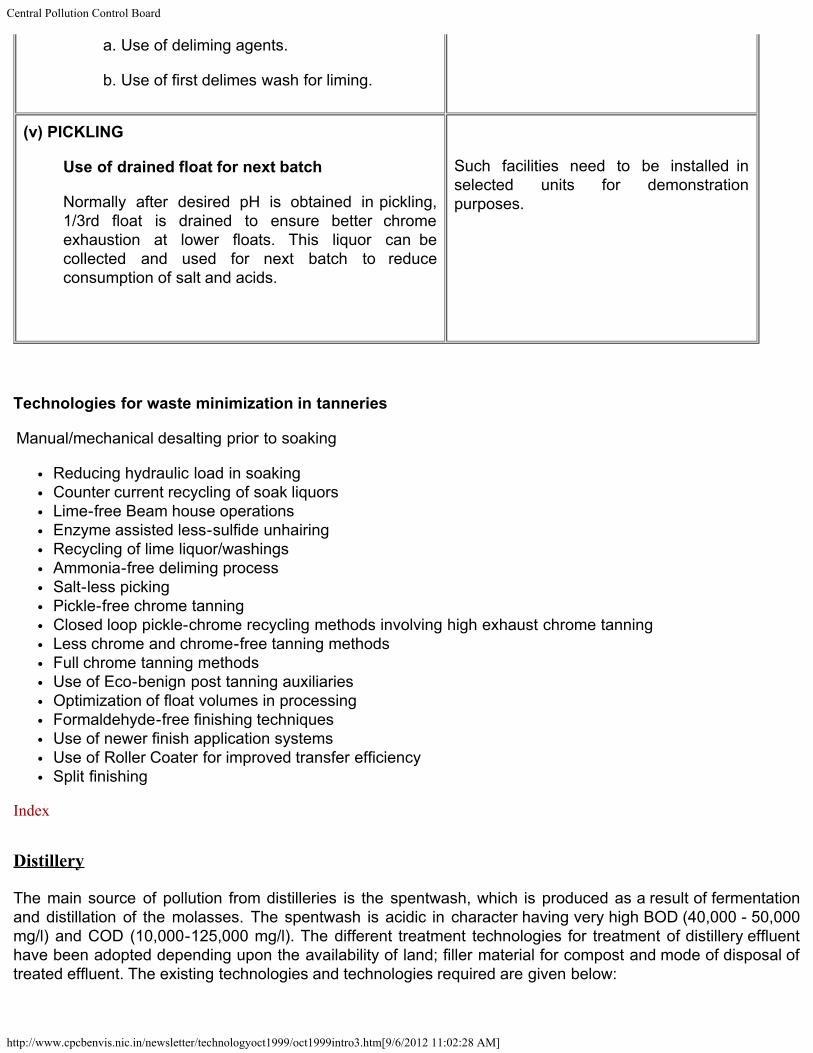
(v) PICKLING
Use of drained float for next batch
Normally after desired pH is obtained in pickling,1/3rd float is drained to ensure better chromeexhaustion at lower floats. This liquor can becollected and used for next batch to reduceconsumption of salt and acids.
Such facilities need to be installed inselected units for demonstrationpurposes.
Technologies for waste minimization in tanneries
Manual/mechanical desalting prior to soaking
Reducing hydraulic load in soakingCounter current recycling of soak liquorsLime-free Beam house operationsEnzyme assisted less-sulfide unhairingRecycling of lime liquor/washingsAmmonia-free deliming processSalt-less pickingPickle-free chrome tanningClosed loop pickle-chrome recycling methods involving high exhaust chrome tanningLess chrome and chrome-free tanning methodsFull chrome tanning methodsUse of Eco-benign post tanning auxiliariesOptimization of float volumes in processingFormaldehyde-free finishing techniquesUse of newer finish application systemsUse of Roller Coater for improved transfer efficiencySplit finishing
Index
Distillery
The main source of pollution from distilleries is the spentwash, which is produced as a result of fermentationand distillation of the molasses. The spentwash is acidic in character having very high BOD (40,000 - 50,000mg/l) and COD (10,000-125,000 mg/l). The different treatment technologies for treatment of distillery effluenthave been adopted depending upon the availability of land; filler material for compost and mode of disposal oftreated effluent. The existing technologies and technologies required are given below:
Central Pollution Control Board
http://www.cpcbenvis.nic.in/newsletter/technologyoct1999/oct1999intro3.htm[9/6/2012 11:02:28 AM]
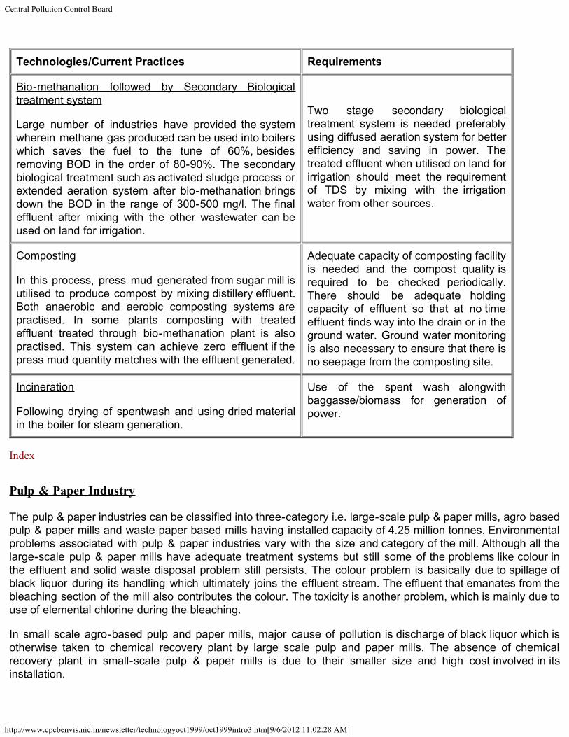
Technologies/Current Practices Requirements
Bio-methanation followed by Secondary Biologicaltreatment system
Large number of industries have provided the systemwherein methane gas produced can be used into boilerswhich saves the fuel to the tune of 60%, besidesremoving BOD in the order of 80-90%. The secondarybiological treatment such as activated sludge process orextended aeration system after bio-methanation bringsdown the BOD in the range of 300-500 mg/l. The finaleffluent after mixing with the other wastewater can beused on land for irrigation.
Two stage secondary biologicaltreatment system is needed preferablyusing diffused aeration system for betterefficiency and saving in power. Thetreated effluent when utilised on land forirrigation should meet the requirementof TDS by mixing with the irrigationwater from other sources.
Composting
In this process, press mud generated from sugar mill isutilised to produce compost by mixing distillery effluent.Both anaerobic and aerobic composting systems arepractised. In some plants composting with treatedeffluent treated through bio-methanation plant is alsopractised. This system can achieve zero effluent if thepress mud quantity matches with the effluent generated.
Adequate capacity of composting facilityis needed and the compost quality isrequired to be checked periodically.There should be adequate holdingcapacity of effluent so that at no timeeffluent finds way into the drain or in theground water. Ground water monitoringis also necessary to ensure that there isno seepage from the composting site.
Incineration
Following drying of spentwash and using dried materialin the boiler for steam generation.
Use of the spent wash alongwithbaggasse/biomass for generation ofpower.
Index
Pulp & Paper Industry
The pulp & paper industries can be classified into three-category i.e. large-scale pulp & paper mills, agro basedpulp & paper mills and waste paper based mills having installed capacity of 4.25 million tonnes. Environmentalproblems associated with pulp & paper industries vary with the size and category of the mill. Although all thelarge-scale pulp & paper mills have adequate treatment systems but still some of the problems like colour inthe effluent and solid waste disposal problem still persists. The colour problem is basically due to spillage ofblack liquor during its handling which ultimately joins the effluent stream. The effluent that emanates from thebleaching section of the mill also contributes the colour. The toxicity is another problem, which is mainly due touse of elemental chlorine during the bleaching.
In small scale agro-based pulp and paper mills, major cause of pollution is discharge of black liquor which isotherwise taken to chemical recovery plant by large scale pulp and paper mills. The absence of chemicalrecovery plant in small-scale pulp & paper mills is due to their smaller size and high cost involved in itsinstallation.
Central Pollution Control Board
http://www.cpcbenvis.nic.in/newsletter/technologyoct1999/oct1999intro3.htm[9/6/2012 11:02:28 AM]
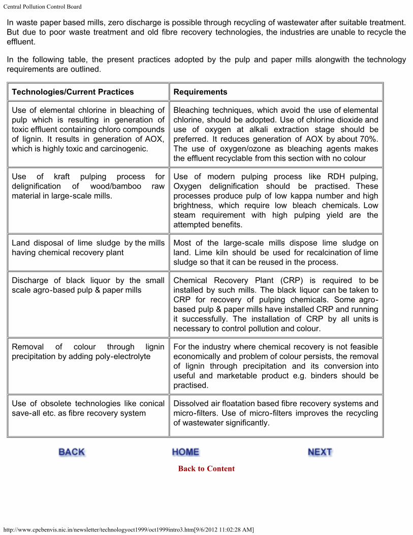
In waste paper based mills, zero discharge is possible through recycling of wastewater after suitable treatment.But due to poor waste treatment and old fibre recovery technologies, the industries are unable to recycle theeffluent.
In the following table, the present practices adopted by the pulp and paper mills alongwith the technologyrequirements are outlined.
Technologies/Current Practices Requirements
Use of elemental chlorine in bleaching ofpulp which is resulting in generation oftoxic effluent containing chloro compoundsof lignin. It results in generation of AOX,which is highly toxic and carcinogenic.
Bleaching techniques, which avoid the use of elementalchlorine, should be adopted. Use of chlorine dioxide anduse of oxygen at alkali extraction stage should bepreferred. It reduces generation of AOX by about 70%.The use of oxygen/ozone as bleaching agents makesthe effluent recyclable from this section with no colour
Use of kraft pulping process fordelignification of wood/bamboo rawmaterial in large-scale mills.
Use of modern pulping process like RDH pulping,Oxygen delignification should be practised. Theseprocesses produce pulp of low kappa number and highbrightness, which require low bleach chemicals. Lowsteam requirement with high pulping yield are theattempted benefits.
Land disposal of lime sludge by the millshaving chemical recovery plant
Most of the large-scale mills dispose lime sludge onland. Lime kiln should be used for recalcination of limesludge so that it can be reused in the process.
Discharge of black liquor by the smallscale agro-based pulp & paper mills
Chemical Recovery Plant (CRP) is required to beinstalled by such mills. The black liquor can be taken toCRP for recovery of pulping chemicals. Some agro-based pulp & paper mills have installed CRP and runningit successfully. The installation of CRP by all units isnecessary to control pollution and colour.
Removal of colour through ligninprecipitation by adding poly-electrolyte
For the industry where chemical recovery is not feasibleeconomically and problem of colour persists, the removalof lignin through precipitation and its conversion intouseful and marketable product e.g. binders should bepractised.
Use of obsolete technologies like conicalsave-all etc. as fibre recovery system
Dissolved air floatation based fibre recovery systems andmicro-filters. Use of micro-filters improves the recyclingof wastewater significantly.
Back to Content
Central Pollution Control Board
http://www.cpcbenvis.nic.in/newsletter/technologyoct1999/oct1999intro4.htm[9/6/2012 11:02:29 AM]
Technologies for Pollution Control Industry
MINING INDUSTRIES
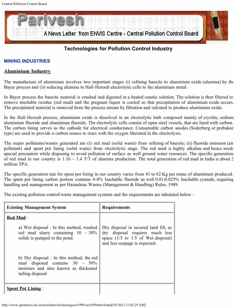
Aluminium Industry
The manufacture of aluminium involves two important stages (i) refining bauxite to aluminium oxide (alumina) by theBayer process and (ii) reducing alumina in Hall-Heroult electrolytic cells to the aluminium metal.
In Bayer process the bauxite material is crushed and digested in a heated caustic solution. The solution is then filtered toremove insoluble residue (red mud) and the pregnant liquor is cooled so that precipitation of aluminium oxide occurs.The precipitated material is removed from the process stream by filtration and calcined to produce aluminium oxide.
In the Hall-Heroult process, aluminium oxide is dissolved in an electrolytic bath composed mainly of cryolite, sodiumaluminium fluoride and aluminium fluoride. The electrolytic cells consist of open steel vessels, that are lined with carbon.The carbon lining serves as the cathode for electrical conductance. Consumable carbon anodes (Soderberg or prebakedtype) are used to provide a carbon source to react with the oxygen liberated in the electrolysis.
The major pollutants/wastes generated are (i) red mud (solid waste) from refining of bauxite; (ii) fluoride emission (airpollutant) and spent pot lining (solid waste) from electrolytic stage. The red mud is highly alkaline and hence needsspecial precaution while disposing to avoid pollution of surface as well ground water resources. The specific generationof red mud in our country is 1.16 – 1.4 T/T of alumina production. The total generation of red mud in India is about 2million TPA.
The specific generation rate for spent pot lining in our country varies from 43 to 62 Kg per tonne of aluminium produced.The spent pot lining carbon portion contains 4-8% leachable fluoride as well 0.01-0.025% leachable cyanide, requiringhandling and management as per Hazardous Wastes (Management & Handling) Rules, 1989.
The existing pollution control/waste management systems and the requirements are tabulated below :
Existing Management System Requirements
Red Mud :
a) Wet disposal : In this method, washedred mud slurry containing 10 – 30%solids is pumped to the pond.
b) Dry disposal : In this method, the redmud disposed contains 30 – 50%moisture and also known as thickenedtailing disposal
Dry disposal in secured land fill, asdry disposal requires much lessspace (1/3 to 1/5 of Wet disposal)and less seepage is expected.
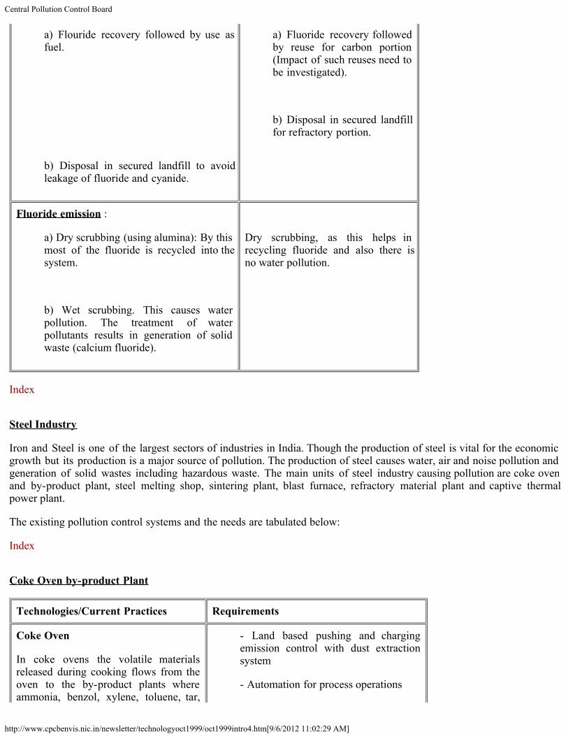
Spent Pot Lining :
Central Pollution Control Board
http://www.cpcbenvis.nic.in/newsletter/technologyoct1999/oct1999intro4.htm[9/6/2012 11:02:29 AM]
a) Flouride recovery followed by use asfuel.
b) Disposal in secured landfill to avoidleakage of fluoride and cyanide.
a) Fluoride recovery followedby reuse for carbon portion(Impact of such reuses need tobe investigated).
b) Disposal in secured landfillfor refractory portion.
Fluoride emission :
a) Dry scrubbing (using alumina): By thismost of the fluoride is recycled into thesystem.
b) Wet scrubbing. This causes waterpollution. The treatment of waterpollutants results in generation of solidwaste (calcium fluoride).
Dry scrubbing, as this helps inrecycling fluoride and also there isno water pollution.
Index
Steel Industry
Iron and Steel is one of the largest sectors of industries in India. Though the production of steel is vital for the economicgrowth but its production is a major source of pollution. The production of steel causes water, air and noise pollution andgeneration of solid wastes including hazardous waste. The main units of steel industry causing pollution are coke ovenand by-product plant, steel melting shop, sintering plant, blast furnace, refractory material plant and captive thermalpower plant.
The existing pollution control systems and the needs are tabulated below:
Index
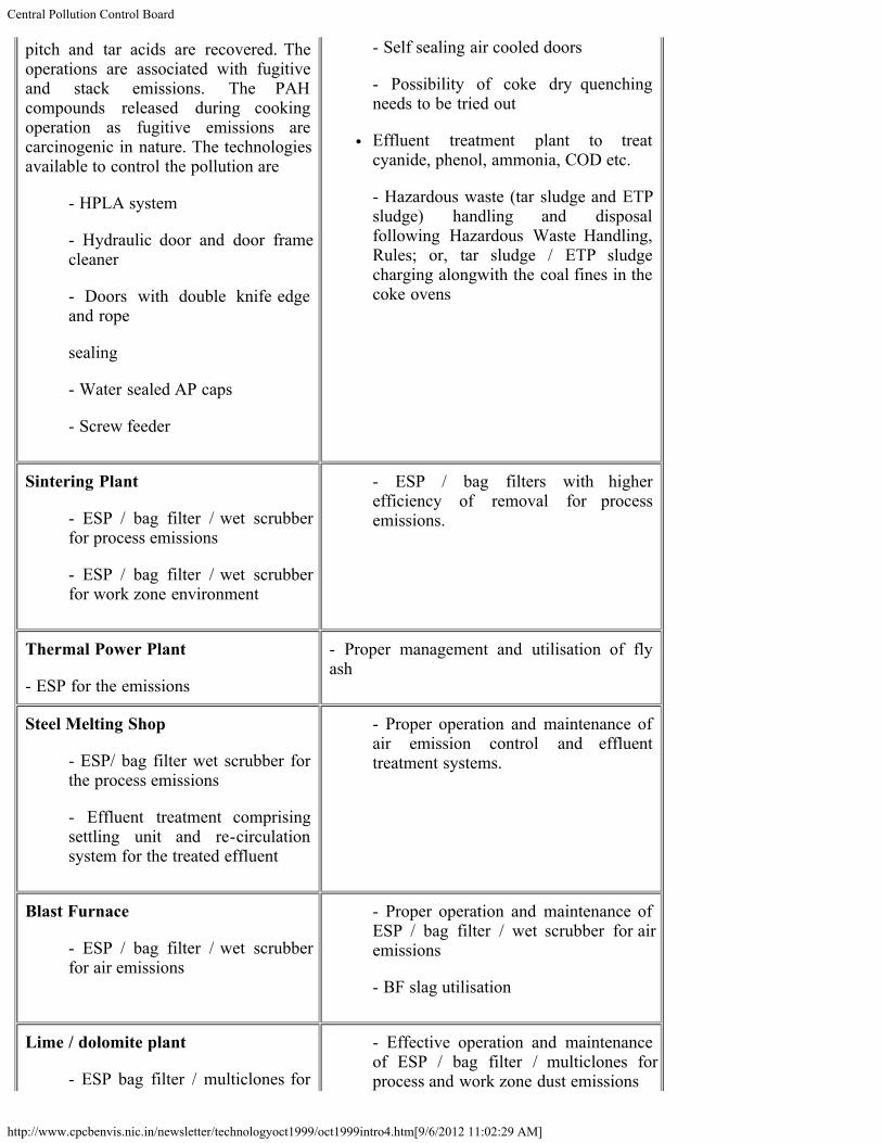
Coke Oven by-product Plant
Technologies/Current Practices Requirements
Coke Oven
In coke ovens the volatile materialsreleased during cooking flows from theoven to the by-product plants whereammonia, benzol, xylene, toluene, tar,
- Land based pushing and chargingemission control with dust extractionsystem
- Automation for process operations
Central Pollution Control Board
http://www.cpcbenvis.nic.in/newsletter/technologyoct1999/oct1999intro4.htm[9/6/2012 11:02:29 AM]
pitch and tar acids are recovered. Theoperations are associated with fugitiveand stack emissions. The PAHcompounds released during cookingoperation as fugitive emissions arecarcinogenic in nature. The technologiesavailable to control the pollution are
- HPLA system
- Hydraulic door and door framecleaner
- Doors with double knife edgeand rope
sealing
- Water sealed AP caps
- Screw feeder
- Self sealing air cooled doors
- Possibility of coke dry quenchingneeds to be tried out
Effluent treatment plant to treatcyanide, phenol, ammonia, COD etc.
- Hazardous waste (tar sludge and ETPsludge) handling and disposalfollowing Hazardous Waste Handling,Rules; or, tar sludge / ETP sludgecharging alongwith the coal fines in thecoke ovens
Sintering Plant
- ESP / bag filter / wet scrubberfor process emissions
- ESP / bag filter / wet scrubberfor work zone environment
- ESP / bag filters with higherefficiency of removal for processemissions.
Thermal Power Plant
- ESP for the emissions
- Proper management and utilisation of flyash
Steel Melting Shop
- ESP/ bag filter wet scrubber forthe process emissions
- Effluent treatment comprisingsettling unit and re-circulationsystem for the treated effluent
- Proper operation and maintenance ofair emission control and effluenttreatment systems.
Blast Furnace
- ESP / bag filter / wet scrubberfor air emissions
- Proper operation and maintenance ofESP / bag filter / wet scrubber for airemissions
- BF slag utilisation
Lime / dolomite plant
- ESP bag filter / multiclones for
- Effective operation and maintenanceof ESP / bag filter / multiclones forprocess and work zone dust emissions
Central Pollution Control Board
http://www.cpcbenvis.nic.in/newsletter/technologyoct1999/oct1999intro4.htm[9/6/2012 11:02:29 AM]
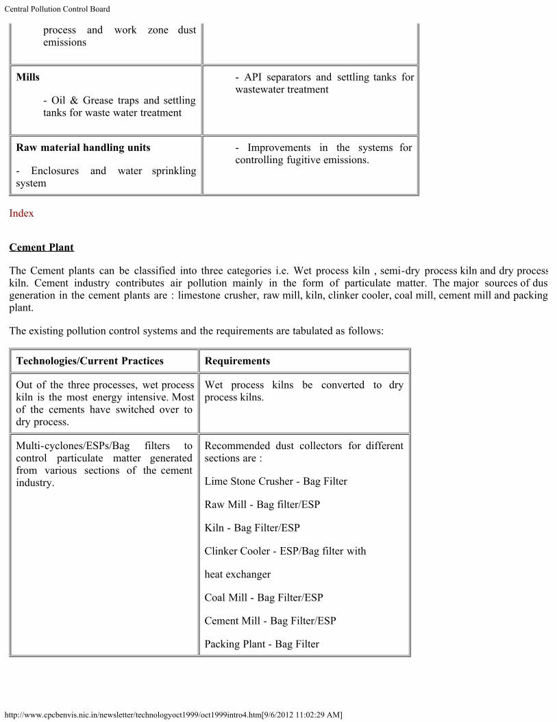
process and work zone dustemissions
Mills
- Oil & Grease traps and settlingtanks for waste water treatment
- API separators and settling tanks forwastewater treatment
Raw material handling units
- Enclosures and water sprinklingsystem
- Improvements in the systems forcontrolling fugitive emissions.
Index
Cement Plant
The Cement plants can be classified into three categories i.e. Wet process kiln , semi-dry process kiln and dry processkiln. Cement industry contributes air pollution mainly in the form of particulate matter. The major sources of dustgeneration in the cement plants are : limestone crusher, raw mill, kiln, clinker cooler, coal mill, cement mill and packingplant.
The existing pollution control systems and the requirements are tabulated as follows:
Technologies/Current Practices Requirements
Out of the three processes, wet processkiln is the most energy intensive. Mostof the cements have switched over todry process.
Wet process kilns be converted to dryprocess kilns.
Multi-cyclones/ESPs/Bag filters tocontrol particulate matter generatedfrom various sections of the cementindustry.
Recommended dust collectors for differentsections are :
Lime Stone Crusher - Bag Filter
Raw Mill - Bag filter/ESP
Kiln - Bag Filter/ESP
Clinker Cooler - ESP/Bag filter with
heat exchanger
Coal Mill - Bag Filter/ESP
Cement Mill - Bag Filter/ESP
Packing Plant - Bag Filter

Central Pollution Control Board
http://www.cpcbenvis.nic.in/newsletter/technologyoct1999/oct1999intro4.htm[9/6/2012 11:02:29 AM]
The Cement industry has potential to utilise the industrial solid waste like flyash and slag as a raw material to produceflyash pozzolana cement, & slag cement. On the one hand, this technology of reuse of waste material will conservenatural resources of limestone and on the other hand it will solve the problem associated with disposal of waste material.It is to be borne in mind that quality-wise flyash pozzolana cement and slag cement is as good as ordinary Portlandcement. Use of flyash, slag and other compatible waste material should be encouraged for utilisation in cementmanufacturing.
The dust collected in pollution control devices is a valuable material. The pay back period of ESP and fabric filter for a3000 TPD cement plant is 10 and 13 months respectively.
Back to Content

Central Pollution Control Board
http://www.cpcbenvis.nic.in/newsletter/technologyoct1999/oct1999intro5.htm[9/6/2012 11:02:30 AM]
Technologies for Pollution Control Industry
THERMAL POWER PLANTS
Thermal Power Plants can be classified based on the type of fuel used. The main categories of the powerplants are coal/lignite based; gas/Naphtha/oil based and Nuclear power plants.
Coal/lignite based thermal power plants
Particulate matter, sulphurdioxide and oxides of nitrogen are the main pollutants emitted form these plantswhich lead to air pollution. The suspended solids, oil and grease are main pollutants in effluent generatedbesides higher temperature in cooling water discharge.
The pollution control systems in practice and the requirements are tabulated below :
Technologies/Current Practices Requirements
- Electrostatic Precipitators havebeen provided to control theemission of particulate matterwith appropriate stack height foradequate dispersion of gaseouspollutants.
- High efficiency ESPs with EPIC controller should beprovided. Further, based on background concentrationor future development of power generation in clusterareas, space provision for installation of flue GasDesulphurisation (FGD) system and DeNOx system, forcontrol of SO2 and NOx emissions are needed so thatthe same control be provided where needed. Forcontrolling smaller particulate emissions from stacks i.e.PM10/PM2.5, bag filters may be used as ESP would nottrap small particles efficiently. Bag filters may also beused in combination with mechanical collectors orESPs.
- To reduce ash content in coal,use of beneficiated coal hasbeen made mandatory w.e.fJune 2001.
- Fluidised Bed combustion (FBC)/CFBC technology forthe solid fuel containing higher ash and sulphur.
- Integrated Coal Gasification combined cycle (IGCC)technology should be tried.
- Wet ash disposal system (leanphase) has been adopted. Someof the plants have dry ashdisposal/collection system vis-a-vis wet disposal in ash pond withwastewater recycling system.
Dense Phase wet ash disposal system. Ash pondwastewater should by recycled hundred percent by thenew plants.
To promote utilisation of flyash, provision for drycollection and storage (Silos) should be made an

Central Pollution Control Board
http://www.cpcbenvis.nic.in/newsletter/technologyoct1999/oct1999intro5.htm[9/6/2012 11:02:30 AM]
integral part of the ash management system.
- Once through cooling system isin practice in some plants.However, new plants haveprovided cooling towers (whichdischarge less quantity of hotwater) .
- In water scarce areas and in locations where powerplants are sited near lakes/reservoir, cooling towersshould be provided.
Index
Gas/Naphtha based Thermal Power plants
Oxides of nitrogen and noise are the main pollutants from these plants. In combined cycle power plants,cooling water discharge at high temperature is a problem for the recipient water bodies.
The available and required pollution control measures in such plants are tabulated below:
Technologies/Current Practices Requirements
- Low NOx burner and steam injectionfor control of oxides of nitrogen.
High efficiency catalysts based fuel gas denitrification(selective catalytic reduction, SCR) system.
- Turbines in acoustic enclosures (indoor) to control noise.
Low noise and low vibration turbines.
- Once through cooling system
Back to Content
Central Pollution Control Board
http://www.cpcbenvis.nic.in/newsletter/technologyoct1999/oct1999intro6.htm[9/6/2012 11:02:31 AM]
Technologies for Pollution Control Industry
READER'S COLUMN
I am glad to see the amount of work you are doing to generate awareness of our present environmental problems. I hopeyour warnings will not fall on deaf ears.
M S Swaminathan
Chairman, M.S.Swaminathan Research Foundation, Chennai
In general, bio-mapping is important for understanding the state of environment. …….I wish you success in developingand using this methodology effectively.
M G K Menon
Chairman, High Power Committee on Hazardous Waste, Delhi
The studies on the stretch of the River Jamuna from Delhi to Etawah and the presentation of the results in the form of amap is an interesting and valuable initiative. The water quality parameters and even the biological organisms resident willundoubtedly vary with the season, the rate of flow of fresh water, rain and the quantities and types of discharges fromhuman habitation along the stretch and the inputs from colonies upstream of Delhi.
S Varadarajan
INSA, New Delhi
The Newsletter (March, 1999) is very informative and well brought out. I enjoyed going through it.
R.A.Mashelkar
Director General, CSIR
I find them (issues of Parivesh) most interesting and informative.
S.Z.Qasim
Vice Chairman, Society for Indian Ocean Studies, New Delhi
I am delighted to see your latest Newsletter (March, 1999) containing interesting results of bio-mapping of riverinesystem in our country, adding another dimension to water quality monitoring. I congratulate you on your leadership in anextraordinarily vital area to the nation’s health and development.
V Ramalingaswami
National Research Professor, AIIMS, New Delhi
I find these Newsletters very interesting.
Central Pollution Control Board
http://www.cpcbenvis.nic.in/newsletter/technologyoct1999/oct1999intro6.htm[9/6/2012 11:02:31 AM]
Tarun das
Director General, CII
Permit me to sincerely congratulate you and your team at CPCB for the excellent pioneering research (on bio-mapping ofrivers) you are undertaking, which will definitely benefit the ecosystem.
P.Murari
Adviser to President, FICCI
Biomonitoring, undoubtely holds promise as a novel approach to water quality monitoring. I take this opportunity to wishevery success to you and your team at CPCB in its future endeavours.
Amit Mitra
Secretary-General, FICCI
We are all aware of the varied activities of CPCB and I am happy that such activities (Bio-mapping of rivers) are nowbeing widely publicised through excellently brought brochures.
Rajat Nandi
SIAM, New Delhi
I take this opportunity to congratulate you and your colleagues in having taken the initiative and completed such a study(Bio-mapping of rivers) on a subject of topical interest. I do hope the Board would take up similar work in other rivers aswell.
K.Rajendran Nair
E.O. & A.S., DoPT, New Delhi
Congratulations for your successful work on the bio-mapping of rivers. It is an endeavor to monitor two environmentalissues (water quality and biodiversity) with a single set of parameters. We believe that this innovative study will motivatefuture studies and invent more accurate relationships between water quality and living organisms.
Surendra Shrestha
Regional Coordinator, UNEP/EAP-AP
The findings of the study as undertaken by your organisation are indeed very interesting and useful for understanding therelationship between the water quality and the living organisms.
Ketut K Ardiantha
Counsellor, Embassy of Indonesia, New Delhi
In my opinion it is a commendable work carried out in the field of bio-monitoring in the Yamuna river and themethodology that could be adopted for bio-mapping of Indian rivers. I am sure you will create greater awareness amonginstitutions and public at large on issues relating to water quality and its impact on living organisms.
L.Lakshminarayan
In-charge, Technology Management, APCTT
Central Pollution Control Board
http://www.cpcbenvis.nic.in/newsletter/technologyoct1999/oct1999intro6.htm[9/6/2012 11:02:31 AM]
I have shared (Parivesh, March, 1999) with my colleagues in the subjects of hydrology, water quality and GIS.
Egbert Pelinck
Director General, ICIMOD, Nepal
I am very much impressed about the data based analysis to polymer demand in India, per capita consumption of plastcsetc.(Parivesh, Sept, 98). ……………We have a fear that in future the plastc would be an alarming problem. Kindly givemore information related to this.
M.David Mansingh
Secretary, SHWET, Trichy
Both these publications (Parivesh, Dec 98 and June 1999) are attractive besides being informative and educative.………………..Your opening remarks (Editorials) and other matters with facts and figures have added grace to the saidpublication.
J R Jindal,
Special Executive Magistrate I Class, Delhi
There is lot of valuable information regarding Auto emission norms (Parivesh, June 1999). Kindly accept ourcomplements for this wonderful and useful issue.
K R Joshi
Advisor, AIILSG, Mumbai
Kindly accept my thanks for an excellent issue (Parivesh, June 1999)
Rajeev Talwar, IAS,
Secretary, Environment and Chairman, DPCC, Delhi
It (Parivesh, June 1999) provides a wealth of information and would be very useful for our students.
Principal
Bhavan's Vidya Mandir, Kochi
The issue (Parivesh, Dec. 1999) has detailed information of CPCB activities in different States in India. We welcomewith appreciation, the setting up of Environmental Surveillance Squad, to monitor the pollution related issues deliberatelyignored by many agencies, causing hazardous health and difficulties to people. We trust, the central notion will havegreater effect on the management and monitor of pollution control and environment, in the country.
M G S Remu
Director, CPD, Bangalore
The subjects ‘Bio-mapping of rivers' and ‘Auto emission' covered by Parivesh is really a source of information on thedeteriorating environment conditions of our country. Our students will definitely find it interesting and informative to gothrough its leaflets.
Central Pollution Control Board
http://www.cpcbenvis.nic.in/newsletter/technologyoct1999/oct1999intro6.htm[9/6/2012 11:02:31 AM]
Vinay Kumar
Principal, DPS Vasant Kunj, New Delhi
It (Parivesh, June 1999) will add boost for the Tamil Nadu Pollution Control Board Library users.
G. Rengasamy
M.S., TNPCB, Chennai
I enjoyed going through the newsletters (Parivesh, March & June, 1999) and also shared these with my staff. We wish tocompliment you and your associates for their research and efforts in finding out a new method of bio-mapping to checkthe water quality by the presence of living organism which will now be adopted for checking the quality of water in allthe rivers of the country. Neatly printed with elegant layout and striking pictures the newsletters indeed look veryimpressive.
Vinod K. Bhola
Manager, Rotary International, New Delhi
It is an excellent concept, but even better to see was its detailed implementation programme……….Encouraged by yourBio-mapping of Rivers, we are putting together a zero order draft of a proposal to the Ministry of Environment andForests to fund such a study all along the coast of India.
E. Desa
Director, National Institute of Oceanography, Goa
These (Parivesh Newsletters) are indeed worthy of the cause being pursued so vigorously by the Central PollutionControl Board.
B.B. Tandon
Secretary, Ministry of Personnel, Public Grievances and Pensions, New Delhi
Back to Content
ENVIS Centre, CPCB,Delhi, India
http://www.cpcbenvis.nic.in/newsletter/news.htm[9/6/2012 11:02:32 AM]
About Envis
Air Pollution
Water Pollution
Noise Pollution
Publications
News Letters
Annual Report
Highlights
News
Team
Home
News Letters
Water Quality Management in IndiaBio-mapping of Rivers - Case study Assam State - August-2005Sewage Pollution -February 2005Dioxin(PCDDs) And Furan(PCDFs) -December 2004Solid Waste Management in Slaughter House -September 2004Polycyclic Aromatic Hydrocarbons (PAHs) In Air And Their Effects On Human Health -November 2003Bio-monitoring of wetlands in wildlife habitats of India Part - I Bird Sanctuaries - July 2003Transport Fuel Adulteration - July 2003
Groundwater - July 2003R&D for Pollution Control CPCB Initiatives - June 2003
Inspection/Maintenance & Certification System for In-use Vehicles - May 2003
Alternative Transport Fuels An Overview-April 2003Odour Pollution and its Control - January 2003
Public Interest Litigations - December 2002
Climate Change - October 2002
Biodiesel As Automobile Fuel - September 2002
Benzene in Air and its Effect on Human Health - February 2002Air Pollution And Human Health-September 2001
Polychlorinated Biphenyls (PCBs) - December 2001
Environmental Management Plan Kanpur Urban Area- May 2001
Bio-Monitoring of Water Quality in Problem Areas - April 2001
Environmental Management System- February 2001
Common Effluent Treatment Plants - November 2000
Polluting Industries
Clean Coal Initiatives - June 2000
Bio-Mapping Of Rivers - March 1999
Auto Emissions - June 1999
Technologies for Pollution Control Industry - October 1999
Hazardous Waste Management - June 1998
Plastic Waste Management - September 1998
Municipal Solid Wastes - June 1997
Click here for LATEST Newsletters
ENVIS Centre, CPCB,Delhi, India
http://www.cpcbenvis.nic.in/newsletter/news.htm[9/6/2012 11:02:32 AM]
Cleaner Production Options for Pulp & Paper Industry - Sept 1997
Zoning Atlas For Siting Industries - June 1996
Bio-Monitoring of Water - September, 1995
Assessment and Development Study of River Basin - March 1995
Depletion of Ozone Layer and Its Implications - September 1994
Agro - based Industries - December 1994