Embed Size (px)
Citation preview


Mira Vasic
Design procedures for the use
o f E B F R P i n s h e a r
strengthening of reinforced
concrete beams.
Italy | 2011
Design Procedures for the Use of EB FRP in Shear Strengthening of Reinforced Concrete Beams
Erasmus Mundus Programme
ADVANCED MASTERS IN STRUCTURAL ANALYSIS OF MONUMENTS AND HISTORICAL CONSTRUCTIONS I
DECLARATION
Name: Mira Vasić
Email: [email protected]
Title of the
Msc Dissertation:
Design procedures for the use of EB FRP in shear strengthening of reinforced
concrete beams
Supervisor(s): Prof. Carlo Pellegrino
Year: 2011
I hereby declare that all information in this document has been obtained and presented in accordance
with academic rules and ethical conduct. I also declare that, as required by these rules and conduct, I
have fully cited and referenced all material and results that are not original to this work.
I hereby declare that the MSc Consortium responsible for the Advanced Masters in Structural Analysis
of Monuments and Historical Constructions is allowed to store and make available electronically the
present MSc Dissertation.
University: University of Padova
Date: September 2nd, 2011
Signature: ___________________________

Design Procedures for the Use of EB FRP in Shear Strengthening of Reinforced Concrete Beams
Erasmus Mundus Programme
II ADVANCED MASTERS IN STRUCTURAL ANALYSIS OF MONUMENTS AND HISTORICAL CONSTRUCTIONS

Design Procedures for the Use of EB FRP in Shear Strengthening of Reinforced Concrete Beams
Erasmus Mundus Programme
ADVANCED MASTERS IN STRUCTURAL ANALYSIS OF MONUMENTS AND HISTORICAL CONSTRUCTIONS III
ACKNOWLEDGEMENTS
I would like to exspress my acknowledge to European Commission and SAHC consortium for
providing me financial support in terms of Erasmus Mundus scholarship and making continuation of
my education in European Union possible.
I would like to give my gratitude to Prof. Carlo Pellegrino from University of Padova for being excellent
tutor and making work on this thesis enjoyable and very productive study, but also for guiding and
advicing me in my future cariere. Many thank to ing. Tommaso D'Antino who has been very helpful
during this research.
I want to present acknowledgment to all professors that gave us lectures during first seven months at
Politecnical University of Barcelona and made this SAHC course precious professional experience.
Special thank to Prof. Pere Roca for taking care of us while staying in Barcelona, organizing trips to
Tarragona and Palma de Mallorca and being supervisor for my coleagues and me during our work on
Tarragona Aqueduct.
On the other hand, I want to say thanks to coleagues that I met during my staying in Spain. All of you
changed my life and made this year amasing as it was, in one way or another. Guys, thank you for all
moments that we shared and all things that you have thougth me.
I also want to give a special thanks to flatmates with whome I shared rooms, flats or hotels in last year.
Thank you for learning me important life lesons and making me being a better person. I am particulary
greateful to my dear greek friends and coleagues, Evina and Thanasi, thank you for each 'gelato' and
'spritz', but also for being so good company in Padova.
I would like to thank to my family for endless support that they were giving me every day on Skype, but
more important also 'offline'. Dad, mom, brow and sisters...Thank you. Sincerely thanks to all my
friends in Serbia and world wide who didn't gave up on me even being thousand kilometers away,
especialy to you Jelena. Also I want to thank to Ivan Ignjatović for supporting me and believing in me.
At last but not the least, I would like to thank to my A. G. for finding me and making things perfect,
giving me all his love...Thank you for beeing you.

Design Procedures for the Use of EB FRP in Shear Strengthening of Reinforced Concrete Beams
Erasmus Mundus Programme
IV ADVANCED MASTERS IN STRUCTURAL ANALYSIS OF MONUMENTS AND HISTORICAL CONSTRUCTIONS
Design Procedures for the Use of EB FRP in Shear Strengthening of Reinforced Concrete Beams
Erasmus Mundus Programme
ADVANCED MASTERS IN STRUCTURAL ANALYSIS OF MONUMENTS AND HISTORICAL CONSTRUCTIONS V
ABSTRACT
The aim of this work is assessment and analysis of the reliability of the most well-known design
models, available for the prediction of the contribution of fiber reinforced polymer (FRP) systems to the
shear capacity of strengthened reinforced concrete beams. In this study, current analytical
formulations for basic shear design and shear strengthening design are presented in detail and main
problems and lacks, being the motivation of this work, are highlighted.
The research is based on the comparison of previous experimental studies with both current design
guidelines and design models recently proposed by several authors, considering also various
recommendations for the angle of inclination of shear cracks. Assessment of design procedures was
done using probabilistic aproach, and several descriptive statistical measures, such as the average
(AVG) and the coefficient of variation (CoV), have been obtained from database, regarding different
strengthening schemes. A more detailed analysis of reduced database was made, considering only U-
jacketed configurations with transversal steel.
Because of its good performance, a detailed investigation on Pellegrino and Modena (2008) model
has been made and in order to predict better results, modification of this model has been proposed.

Design Procedures for the Use of EB FRP in Shear Strengthening of Reinforced Concrete Beams
Erasmus Mundus Programme
VI ADVANCED MASTERS IN STRUCTURAL ANALYSIS OF MONUMENTS AND HISTORICAL CONSTRUCTIONS
Design Procedures for the Use of EB FRP in Shear Strengthening of Reinforced Concrete Beams
Erasmus Mundus Programme
ADVANCED MASTERS IN STRUCTURAL ANALYSIS OF MONUMENTS AND HISTORICAL CONSTRUCTIONS VII
Titolo
della Tesi di Master:
Procedure di Calcolo per l’Uso di EB FRP nel Rinforzo a Taglio di Travi in
Cemento Armato
ESTRATTO
Lo scopo del presente lavoro consiste nella valutazione e nell’analisi dell’affidabilità dei più noti
modelli di calcolo disponibili per la previsione del contributo dei sistemi di rinforzo in materiale
composito (FRP) per la resistenza a taglio di travi in cemento armato. In tale studio sono presentate in
dettaglio le attuali formulazioni analitiche per il progetto a taglio senza rinforzo e per il progetto a taglio
di elementi rinforzati con FRP, e sono evidenziati principali problemi e carenze.
La ricerca è basata sul confronto di precedenti studi sperimentali con gli attuali codici normativi e
modelli di calcolo, recentemente proposti da diversi autori, considerando anche l’inclinazione
dell’angolo delle fessure a taglio. La valutazione delle procedure di progetto è stata effettuata usando
diverse misure statistiche, come la media (AVG) ed il coefficiente di variazione (CoV), ottenuti dal
database, con riferimento a diversi schemi di rinforzo. È stata condotta un’analisi più dettagliata su un
database ridotto, considerando solo la configurazione di rinforzo a U con armatura trasversale.
Date le buone prestazioni, è stato studiato in dettaglio il modello di Pellegrino e Modena (2008) e, al
fine di predire migliori risultati, è stata proposta una lieve modifica di tale modello.

Design Procedures for the Use of EB FRP in Shear Strengthening of Reinforced Concrete Beams
Erasmus Mundus Programme
VIII ADVANCED MASTERS IN STRUCTURAL ANALYSIS OF MONUMENTS AND HISTORICAL CONSTRUCTIONS
Design Procedures for the Use of EB FRP in Shear Strengthening of Reinforced Concrete Beams
Erasmus Mundus Programme
ADVANCED MASTERS IN STRUCTURAL ANALYSIS OF MONUMENTS AND HISTORICAL CONSTRUCTIONS IX
Naslov
Master Disertacije:
Proračun otpornosti na smicanje greda ojačanih FRP laminatima
REZIME
Cilj ovog rada je procena pouzdanostii najpoznatijih modela za proračun udela sistema ojačanja greda
putem/pomoću polimera armiranih vlaknim (FRP sistema) u nosivosti na smicanje armiranobetonskih
greda. U ovoj studiji, detaljno su objašnjene važeće analitičke formulacije za proračun nosivosti na
smicanje neojačanih/klasičnih i ojačanih greda, a takođe su istaknuti glavni problemi i nedostaci ovih
procedura, što je ujedno i (primarni cilj) ovog rada.
Istraživanje je bazirano na poređenju dosadašnjih, u literaturi dostupnih eksperimentalnih ispitivanja
greda ojačanih FRP sistemima sa važećim standardima, ali i sa modelima koji su u skorije vreme
predloženi od strane više autora; sa posebnim osvrtom na različite preporuke propisa za vrednost ugla
smičuće prsline. Za analizu ovih proračunskih modela, korišćen je probabilistički pristup u okviru koga
su su prosečna vrednost i koeficijent varijacije, dobijene obradom baze podataka za različite šeme
ojačanja. Detaljno je analizirana baza podataka i redukovana na podatke koji se odnose samo na U-
konfiguracije ojačanja.
S obzirom na relativno dobre rezultate poređenja eksperimentalnih i teorijskih rezultata dobijenih
upotrebom modela Pelegrina i Modene (2008), ovaj model je detaljno analiziran, i u cilju njegovog
poboljšanja određene modifikacije su predložene u ovom radu.
Design Procedures for the Use of EB FRP in Shear Strengthening of Reinforced Concrete Beams
Erasmus Mundus Programme
X ADVANCED MASTERS IN STRUCTURAL ANALYSIS OF MONUMENTS AND HISTORICAL CONSTRUCTIONS
Design Procedures for the Use of EB FRP in Shear Strengthening of Reinforced Concrete Beams
Erasmus Mundus Programme
ADVANCED MASTERS IN STRUCTURAL ANALYSIS OF MONUMENTS AND HISTORICAL CONSTRUCTIONS XI
TABLE OF CONTENT
1. INTRODUCTION 1
1.1 Motivation and objectives of the study 1
1.2 Outline of the study 2
2. CURRENT ANALYTICAL FORMULATIONS 3
3. REVIEW OF CURRENT DESIGN GUIDELINES FOR NON-STRENGTHENED
STRUCTURES 9
3.1 EUROCODE 2 (2004) 9
3.2 ACI 318M-08 (2008) 11
3.3 fib MC10 (2010) 11
4. REVIEW OF CURRENT DESIGN GUIDELINES FOR STRENGTHENED STRUCTURES 13
4.1 fib - TG 9.3 (2001) 13
4.2 CNR-DT200 (2004) 15
4.3 ACI 440.2R (2008) 18
4.4 fib ’09 - draft 2009 20
5. RECENT DESIGN MODEL PROPOSALS 23
5.1 Chen and Teng (2003a) 23
5.2 Carolin and Täljsten (2005) 26
5.3 Pellegrino and Modena (2008) 27
5.4 Bukhari et al. (2010) 29
5.5 Modifi and Chaallal (2011) 30
6. METHODOLOGY FOR ANALYZING EXPERIMENTAL VS THEORETICAL VALUES 33
6.1 Database Description 33
6.2 The Total Shear Strength 40
6.3 Analyzed design procedures 40
6.4 General statistical analysis procedures 41
Design Procedures for the Use of EB FRP in Shear Strengthening of Reinforced Concrete Beams
Erasmus Mundus Programme
XII ADVANCED MASTERS IN STRUCTURAL ANALYSIS OF MONUMENTS AND HISTORICAL CONSTRUCTIONS
7. RESULTS AND DISCUSSION 43
7.1 Assessment of Pellegrino and Modena (2008) model and its improvement 43
7.2 Results obtained using the DB 50
7.3 Results obtained using the RDB 51
8. CONCLUSIONS 55
8.1 Model of Pellegrino and Modena 55
8.2 Basic codes 55
8.3 Angle inside basic code 55
8.4 Models 56
8.5 U-jacketing with transversal steel configuration 56
8.6 General conclusions 56
9. REFERENCES 57
Design Procedures for the Use of EB FRP in Shear Strengthening of Reinforced Concrete Beams
Erasmus Mundus Programme
ADVANCED MASTERS IN STRUCTURAL ANALYSIS OF MONUMENTS AND HISTORICAL CONSTRUCTIONS XIII
LIST OF FIGURES
Figure 1 - Lateral view of FRP shear strengthening (CNR-DT200 2004) 3
Figure 2 - Cross section of FRP strengthened members (CNR-DT200 2004 3
Figure 3 - FRP Shear contribution according to CNR (Barros, Dias and Lima 2007) 5
Figure 4 - Failure modes of beams by Pellegrino and Modena in (2002) and (2006) 6
Figure 5 - Notation for angles of shear cracks and FRP fiber orientation according to fib ‘01 (2001) 13
Figure 6 - Notation for shear strengthening using FRP strips (CNR-DT200 2004) 15
Figure 7 - Illustration of the dimensional variables used in shear-strengthening recommendations of ACI 440.2R (American Concrete Institute (ACI) Committee 440 2008) 19
Figure 8 - Chen and Teng notation for a general shear strengthening scheme (Chen, Teng and Chen, RC beams shear-strengthened with FRP: shear resistance contributed by FRP 2010) 24
Figure 9 - Fiber alignment and crack angle, Carolin and Taljsten (2005) 26
Figure 10 - Shape of the fracture surface of “U-jacketed” (a) and side-bonded beams (b) 27
Figure 11 - Forces acting in the cross section of “U-jacketed” (a) and side-bonded beams (b) 28
Figure 12 - U-jacketed configurations without (graphs a and b) and with transversal reinforcement graphs c and d) 45
Figure 13 - Side bonded configurations without (graphs a and b) and with transversal reinforcement graphs c and d) 46
Figure 14 - Best prediction results in general overview: U-jacketed configurations without and with transversal steel and side bonded configurations without and with transversal steel (graphs a,b,c and d, respectively) 50

Design Procedures for the Use of EB FRP in Shear Strengthening of Reinforced Concrete Beams
Erasmus Mundus Programme
XIV ADVANCED MASTERS IN STRUCTURAL ANALYSIS OF MONUMENTS AND HISTORICAL CONSTRUCTIONS
Design Procedures for the Use of EB FRP in Shear Strengthening of Reinforced Concrete Beams
Erasmus Mundus Programme
ADVANCED MASTERS IN STRUCTURAL ANALYSIS OF MONUMENTS AND HISTORICAL CONSTRUCTIONS XV
LIST OF TABLES
Table 1 - Experimental Database 35
Table 2 - Continuation of Table 1 36
Table 3 - Continuation of Table 1 37
Table 4 - Continuation of Table 1 38
Table 5 - Continuation of Table 1 39
Table 6 - Design procedures for analyzing DB 40
Table 7 - Comparison of results for Modena and Pellegrino model 44
Table 8 - Values for Coefficient of Variation (CoV) obtained from DB 47
Table 9 - Values for the Average (AVG) obtained from DB 48
Table 10 - Results from RDB for θ=45°and θ=36° 52
Table 11 - Results from RDB for θ=var and θ=35/45° 53

Design Procedures for the Use of EB FRP in Shear Strengthening of Reinforced Concrete Beams
Erasmus Mundus Programme
XVI ADVANCED MASTERS IN STRUCTURAL ANALYSIS OF MONUMENTS AND HISTORICAL CONSTRUCTIONS
Design Procedures for the Use of EB FRP in Shear Strengthening of Reinforced Concrete Beams
Erasmus Mundus Programme
ADVANCED MASTERS IN STRUCTURAL ANALYSIS OF MONUMENTS AND HISTORICAL CONSTRUCTIONS 1
1. INTRODUCTION
Necessity for structural strengthening may be induced by variety of reasons, such as ageing, lack of
maintenance, damages due to accidental or natural causes, degradation caused by poor initial
construction conditions or bad quality of used material; but also with other problems related to upgrading
or rehabilitation of existing reinforced concrete (RC) structures.
In last two decades, development of materials that will replace those used in traditional techniques of
strengthening, such as steel and concrete, resulted in experimental investigation of their application,
efficiency and safety of techniques, durability, properties of material itself and compatibility with other
materials.
As one of the methods that has been widely accepted all over the world, bonding of fiber reinforced
polymer (FRP) composites with a suitable epoxy adhesive, has shown to be applicable to many types of
RC structures. Currently, the use of this modern material may be in general classified as axial (confining),
flexural and shear strengthening. Many efforts are made in proposing design recommendations regarding
flexural strengthening and have been experimentally confirmed in the past. On the other hand, the shear
behaviour of RC beams strengthened with FRP is still not well understood and interpreted in current
design guidelines and models.
1.1 Motivation and objectives of the study
Since the usage of FRP in building retrofit has shown as an effective technique, the field of its application
is continuously growing. The result in last decade is implementation of experimentally based analytical
models for design, detailing and installations of FRP strengthening systems into design guidelines and
codes. The intent of the assessment of existing recommendations and models is to verify their validity,
safety and quality of their predictions.
This work reviews not only the recommendations for shear strengthening analysis produced by the
Fèderation Internationale du Bèton, fib buletin 14 (2001) and fib bulletin – draft (2009), the Italian National
Research Council (CNR-DT200 2004) and the American Concrete Institute ACI440 (2008); but also
models recently proposed by several groups of authors: Chen and Teng (2003a), Carolin and Täljsten
(2005), Pellegrino and Modena (2008), Bukhari et al. (2010), and Modifi and Chaallal (2011). This study
also addresses the main lacks of design procedures for strengthening of RC beams with FRP, such as
non considering the interaction between the external FRP and internal transversal steel reinforcement, or
assuming the constant angle of diagonal crack with respect to the member axis, and to be equal to 45°.
Since many scientists such as Pellegrino and Modena (2002), Barros (2007) and Colotti (2011) have

Design Procedures for the Use of EB FRP in Shear Strengthening of Reinforced Concrete Beams
Erasmus Mundus Programme
2 ADVANCED MASTERS IN STRUCTURAL ANALYSIS OF MONUMENTS AND HISTORICAL CONSTRUCTIONS
pointed out strong influence of these parameters to the efficiency of the shear strengthening rehabilitation
technique, further investigation in this field and improvement of codes and models is necessary in order to
obtain more sophisticated results.
1.2 Outline of the study
This work is a critical review of current guidelines and recently proposed models, regarding weaknesses of
shear strengthening design procedures.
A description of the basis of the current codes for non-strengthened structures and their design procedure
are presented in Chapter 3.
In Chapter 4, a description of the analytical approach of the current design guidelines is given, while
recently proposed models by several authors and their proposed equations are presented in Chapter 5.
Collected data base of an experimental investigation on reinforced concrete (RC) rectangular beams
strengthened in shear with externally bonded FRP is presented. Methodology for analyzing experimental
vs. theoretical values and general statistical procedure used in this study is explained in Chapter 6.
Finally, a comparison between different basic codes and models was performed within the objective of
study. Results are given and discussed in Chapter 7. In this chapter are also given results, discussion and
proposal of modified Pellegrino and Modena model.
At the end, in Chapter 8, conclusions considering basic codes, models, angles of shear cracks and
general conclusions are summarized.
Design Procedures for the Use of EB FRP in Shear Strengthening of Reinforced Concrete Beams
Erasmus Mundus Programme
ADVANCED MASTERS IN STRUCTURAL ANALYSIS OF MONUMENTS AND HISTORICAL CONSTRUCTIONS 3
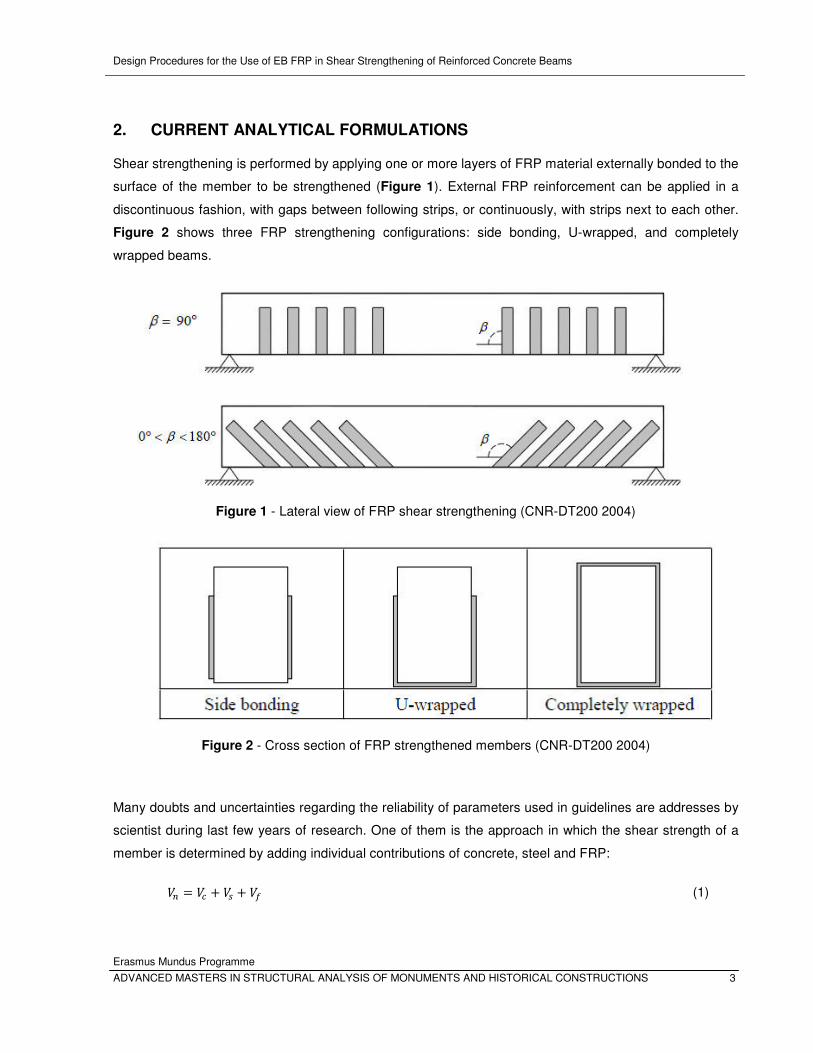
2. CURRENT ANALYTICAL FORMULATIONS
Shear strengthening is performed by applying one or more layers of FRP material externally bonded to the
surface of the member to be strengthened (Figure 1). External FRP reinforcement can be applied in a
discontinuous fashion, with gaps between following strips, or continuously, with strips next to each other.
Figure 2 shows three FRP strengthening configurations: side bonding, U-wrapped, and completely
wrapped beams.
Figure 1 - Lateral view of FRP shear strengthening (CNR-DT200 2004)
Figure 2 - Cross section of FRP strengthened members (CNR-DT200 2004)
Many doubts and uncertainties regarding the reliability of parameters used in guidelines are addresses by
scientist during last few years of research. One of them is the approach in which the shear strength of a
member is determined by adding individual contributions of concrete, steel and FRP:
�� = �� + �� + �� (1)
Design Procedures for the Use of EB FRP in Shear Strengthening of Reinforced Concrete Beams
Erasmus Mundus Programme
4 ADVANCED MASTERS IN STRUCTURAL ANALYSIS OF MONUMENTS AND HISTORICAL CONSTRUCTIONS
This simple adding of force components and independency between them is one of the assumptions that
have shown as inadequate interpretation of strengthened member behaviour, since it eliminates
contribution of FRP (��) in nominal shear strength. Several models for strengthened structures propose
equations for contribution of FRP composites (��), which configures in equation (1), while for
contributions of concrete (��) and steel (��) they recommend usage of current guidelines for non-
strengthened structures.
Most of the equations that predict contribution of FRP are not calibrated taking into account different
approaches of basic codes, which is consequence of individual interpretation of these codes by scientists
who are proposing models. Current basic codes for nonstrengthened structures, Eurocode 2, ACI 318M-
08 and fib MC10 have different approaches to shear design procedure regarding contributions of steel and
concrete, but also the angle of shear crack.
Lima and Barros (2011) performed reliability analysis of the collected experimental data and concluded
that the orientation of the critical shear crack �� may be quite different from the suggested value
recommended by the design codes. This indicated that �� depends on the existing conventional shear
reinforcement in the strengthened beam. This fact is one more direct implication for the FRP contribution
to the shear resistance, since it supports the unreliable predictions obtained in many cases with the
studied formulations proposed by guidelines.
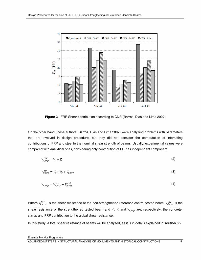
The program of experiment performed by a group of authors (Barros, Dias and Lima (2007)) included four
series of shear reinforced concrete beams. During comparison of experimental and theoretical data,
several different values for angle of shear crack were considered (Figure 3 - FRP Shear contribution
according to CNR ). Although using various values of the critical shear crack, each series was constituted
by beams with only strips or FRP sheet as shear reinforcement and in this way failed in considering steel
and FRP reinforcement interaction.
Design Procedures for the Use of EB FRP in Shear Strengthening of Reinforced Concrete Beams
Erasmus Mundus Programme
ADVANCED MASTERS IN STRUCTURAL ANALYSIS OF MONUMENTS AND HISTORICAL CONSTRUCTIONS 5
Figure 3 - FRP Shear contribution according to CNR (Barros, Dias and Lima 2007)
On the other hand, these authors (Barros, Dias and Lima 2007) were analyzing problems with parameters
that are involved in design procedure, but they did not consider the computation of interacting
contributions of FRP and steel to the nominal shear strength of beams. Usually, experimental values were
compared with analytical ones, considering only contribution of FRP as independent component:
��,������ = �� + �� (2)
��,������ = �� + �� + ��,��� (3)
��,��� = ��,������ − ��,������ (4)
Where ��,������ is the shear resistance of the non-strengthened reference control tested beam, ��,������ is the
shear resistance of the strengthened tested beam and ��, �� and ��,��� are, respectively, the concrete,
stirrup and FRP contribution to the global shear resistance.
In this study, a total shear resistance of beams will be analyzed, as it is in details explained in section 6.2.
Design Procedures for the Use of EB FRP in Shear Strengthening of Reinforced Concrete Beams
Erasmus Mundus Programme
6 ADVANCED MASTERS IN STRUCTURAL ANALYSIS OF MONUMENTS AND HISTORICAL CONSTRUCTIONS
Another observation that impacts on reliability of models is not taking into account interaction between
FRP and steel. Comparison of experimental tests and current analytical models, performed by Pellegrino
and Modena (2008), has shown that the interaction between an external FRP and an internal transverse
steel reinforcement, which is not considered in some actual code recommendations, strongly influences
the efficiency of the shear strengthening rehabilitation technique.
In addition, one of the reasons why the shear behaviour of RC beams strengthened with FRP is not well
understood is that most of the tests in past have been carried out on simply supported beams without
steel stirrups, but models for both configurations with and without steel are based on these experiments.
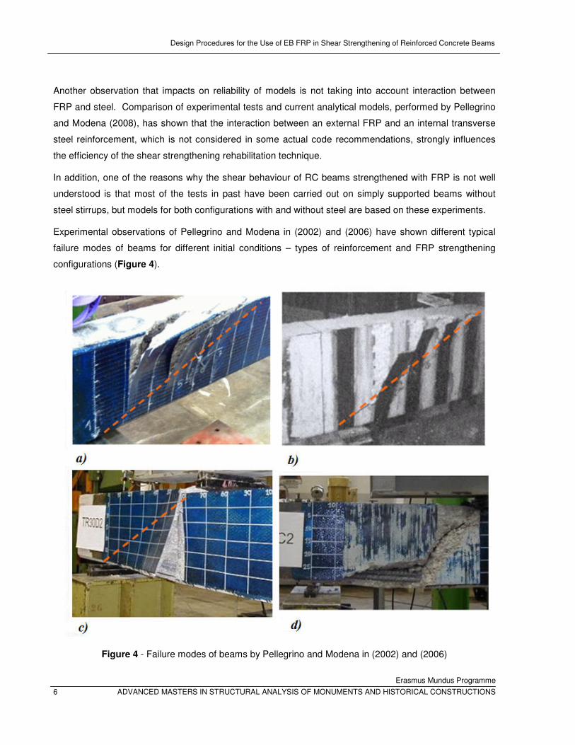
Experimental observations of Pellegrino and Modena in (2002) and (2006) have shown different typical
failure modes of beams for different initial conditions – types of reinforcement and FRP strengthening
configurations (Figure 4).
Figure 4 - Failure modes of beams by Pellegrino and Modena in (2002) and (2006)
Design Procedures for the Use of EB FRP in Shear Strengthening of Reinforced Concrete Beams
Erasmus Mundus Programme
ADVANCED MASTERS IN STRUCTURAL ANALYSIS OF MONUMENTS AND HISTORICAL CONSTRUCTIONS 7
These authors concluded from experimental results that for U-jacketed beams, both with internal steel
stirrups (Figure 4a) and without (Figure 4b), peeling-off of the FRP with the concrete cover occures in a
lateral triangular portion above the principal diagonal crack from bearing location to the load point. On the
other hand, for side-bonded beams, with same initial steel reinforcement (with internal steel stirrups -
Figure 4c and without - Figure 4d), this peeling-off occures above the principal diagonal crack.
Analyzing a computational model for shear interaction between FRP strips and steel stirrups, a
group of authors (G. Chen, J. Teng, et al., Interaction between Steel Stirrups and Shear-Strengthening
FRP Strips in RC Beams 2010) concluded that the maximum shear contributions of steel stirrups and FRP
may not be reached simultaneously, so that their combined contribution may be less than the sum of the
respective peak values of �� and ��. Also, in the evaluation of shear strength, the simultaneous use of
these maximum values is an unconservative approach. For accurate evaluation of the shear resistance
they recommended the determination of the maximum value of the combined contribution of steel stirrups
and FRP strips.
The parameters that have the greatest influence on the shear behavior of RC members strengthened with
EB FRP and the role of these parameters in current design codes were deeply analyzed by Modifi and
Chaallal (2011). One of them is cracking angle, for which they concluded that should be implemented in
calculation of �� and proposed their design equation (this proposal will be disscused later on).
Finally, main questions that are result of state of art and will be analyzed in this study are:
1. Are the approaches recommended by current basic codes still valid when strengthening is
applied?
2. Do the current recommendations for shear crack angle θ, both in basic codes and models for
strengthened structures have impact on results?
3. Does the presence of transverse internal steel or external FRP have any effect on the shear
design procedure?

Design Procedures for the Use of EB FRP in Shear Strengthening of Reinforced Concrete Beams
Erasmus Mundus Programme
8 ADVANCED MASTERS IN STRUCTURAL ANALYSIS OF MONUMENTS AND HISTORICAL CONSTRUCTIONS
Design Procedures for the Use of EB FRP in Shear Strengthening of Reinforced Concrete Beams
Erasmus Mundus Programme
ADVANCED MASTERS IN STRUCTURAL ANALYSIS OF MONUMENTS AND HISTORICAL CONSTRUCTIONS 9
3. REVIEW OF CURRENT DESIGN GUIDELINES FOR NON-STRENGTHENED
STRUCTURES
As a remark, it has to be said that the equations reviewed in this study are presented in the units
of the codes, unless otherwise specified. The names and symbols of the used variables correspond to the
ones used in the codes, models or articles investigated and have been explained in details or if it possible
illustrated with figures.
3.1 EUROCODE 2 (2004)
For the design of shear reinforcement, Eurocode (2004) recommends the variable strut inclination method.
In this method, it is assumed that the shear force is entirely resisted by a truss consisting of concrete
struts acting in compression equilibrated by shear reinforcement in tension. Limiting values for the angle of
the concrete compression struts to the longitudinal axis of the beam are:
21,8∘ ≤ ≤ 45∘ (5)
Indicated by:
1 ≤ ��� ≤ 2,5 (6)
The effective crushing strength of concrete is:
���,� � = !�" ∙ $" ∙ 0,9 ∙ ' ∙ () ∙ *��/(cot + tan )
(7)
For *�1 ≤ 60345 6) = 0,6
For *�1 ≥ 60345 6) = 0,9 − *�1/200 > 0,5
!�" = 1
a) For members not requiring design shear reinforcement, the design value for the shear
resistance is given by:
��� = 9:;<���,�; ���,� �> (8)
Design Procedures for the Use of EB FRP in Shear Strengthening of Reinforced Concrete Beams
Erasmus Mundus Programme
10 ADVANCED MASTERS IN STRUCTURAL ANALYSIS OF MONUMENTS AND HISTORICAL CONSTRUCTIONS
���,� = ?@��,� ∙ A ∙ (100 ∙ B) ∙ *�1)) CD + A) ∙ E��F ∙ $" ∙ ' (9)
With a minimum of:
���,��G� = H6�G� + A) ∙ E��I ∙ $" ∙ ' (10)
Where *�1 is in [MPa], d in [mm]
A = 1 + J200' ≤ 2,0 (11)
B) = K�L$" ∙ ' ≤ 0,02 (12)
6�G� = 0,035 ∙ AC/N ∙ *�1)/N
(13)
Where K�L is the area of the tensile reinforcement and $" is the smallest width of the cross-section in the
tensile area [mm]. The recommended value for @��,� is 0,18/γc, and for k1 is 0,15.
b) For members with inclined shear reinforcement, the design value for the shear resistance is
given by:
��� = 9:;<���,�; ���,� �> (14)
And shear reinforcement in tension capacity is:
���,� = K�"O ∙ 0,9 ∙ ' ∙ *P"� ∙ (��� + ��� Q) ∙ O:; Q (15)
In equations (7) and (15), represents the angle of shear cracks, and it is recommended by Eurocode 2
to be assumed equal to 45° unless a more detailed calculation is made.

Design Procedures for the Use of EB FRP in Shear Strengthening of Reinforced Concrete Beams
Erasmus Mundus Programme
ADVANCED MASTERS IN STRUCTURAL ANALYSIS OF MONUMENTS AND HISTORICAL CONSTRUCTIONS 11
Equation (14) shows that the variable angle truss model is an idealisation in which whole shear force is
assumed to be resisted by the stirrups. In reality, part of the shear force is resisted by ��, which is not
constant as assumed in equation (9).
3.2 ACI 318M-08 (2008)
Design of cross sections subject to shear should be based on nominal shear strength computed by:
�� = �� + �� (16)
Where �� is nominal shear strength provided by concrete, and calculated as:
�� = 0,17 ∙ S ∙ T*′� ∙ $" ∙ ' (17)
�� is nominal shear strength provided by shear reinforcement, and calculated for:
a) Member where used shear reinforcement is perpendicular to axis of member
�� = KV ∙ ' ∙ *P�O (18)
Where KV is the area of shear reinforcement within spacing O.
b) Member where inclined stirrups are used as shear reinforcement:
�� = KV ∙ ' ∙ (sin ! + cos !) ∙ *P�O (19)
Where ! is the angle between inclined stirrups and longitudinal axis of the member, and s is measured in
direction parallel to longitudinal reinforcement.
From equation (19) it can be observed that ACI 318M-08 (2008) assumes angle of shear cracks to be
equal to = 45°, and reliability of this approach will be analyzed in further study of this document.
3.3 fib MC10 (2010)
The design shear resistance of a web or slab shall be determined as:
��� = 9:;<���,� + ���,�; ���,� �> (20)
Design Procedures for the Use of EB FRP in Shear Strengthening of Reinforced Concrete Beams
Erasmus Mundus Programme
12 ADVANCED MASTERS IN STRUCTURAL ANALYSIS OF MONUMENTS AND HISTORICAL CONSTRUCTIONS
���,� � = A� ∙ *�1Z� ∙ $" ∙ 0,9 ∙ ' ∙ ��� + ��� !1 + (��� )N (21)
Where is the selected inclination of the compression stresses; ! is the inclination of the stirrups relative
to the beam axis, so the design shear resistance provided by the stirrups may be calculated as:
���,� = K�"O" ∙ 0,9 ∙ ' ∙ *P"� ∙ (cot + cot !) ∙ sin ! (22)
The design shear resistance attributed to the concrete can be taken as:
���,� = AV ∙ T*�1Z� ∙ $" ∙ 0,9 ∙ ' (23)
Where the value of T*�1 shall not be taken as greater than 8 MPa.
fib MC10 proposes three levels of approximation in terms of complexity, effort and level of detail. In this
study, considering available data on experimental results that will be analyzed, first level will be used:
Level I Approximation:
= 45° or = 36° (in case of early design stages) A� = 0,5 ∙ [ 30*P1\) CD ≤ 0,5 (24)
for B" = 0
AV = 2001000 + 1,3 ∙ 0,9 ∙ ' ≤ 0,15 (25)
for B" ≥ 0,08 ∙ T�]^�_^
AV = 0,15
(26)
Design Procedures for the Use of EB FRP in Shear Strengthening of Reinforced Concrete Beams
Erasmus Mundus Programme
ADVANCED MASTERS IN STRUCTURAL ANALYSIS OF MONUMENTS AND HISTORICAL CONSTRUCTIONS 13
4. REVIEW OF CURRENT DESIGN GUIDELINES FOR STRENGTHENED
STRUCTURES
Current guidelines are truss-model based, and adopted notation to define the main geometric properties
of FRP shear reinforcement is given in figures and has been reviewed for each guideline.
4.1 fib - TG 9.3 (2001)
Provisions of fib - TG 9.3 (2001) on shear strengthening of RC beams are based on the regression of
experimental results carried out by Triantafillou and Antonopoulos (2000). The shear capacity of a
strengthened element according to (fib task group 9.3 2001) should be calculated as follows:
��� = min (��� + �"� + ��� , ���,N) (27)
Where ��� and �"� are designed values of concrete and transversal steel, respectively and can be
calculated according to current basic codes for nonstrengthened structures.
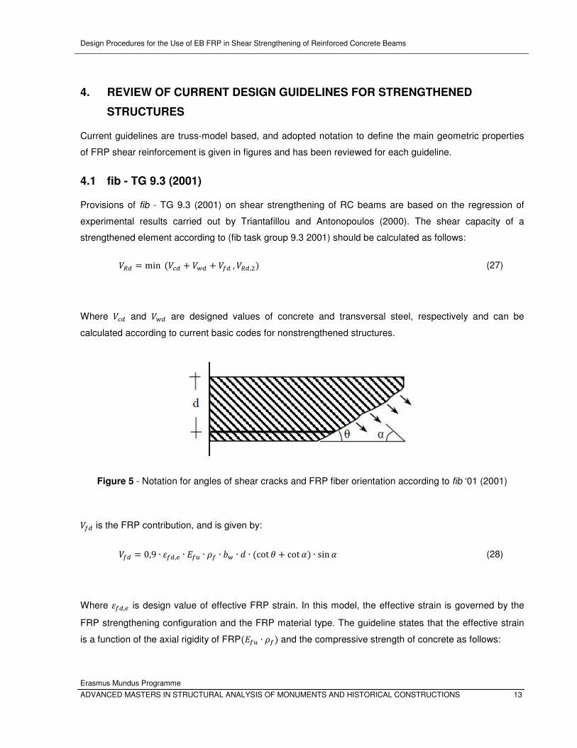
Figure 5 - Notation for angles of shear cracks and FRP fiber orientation according to fib ‘01 (2001)
��� is the FRP contribution, and is given by:
��� = 0,9 ∙ a��,� ∙ b�c ∙ B� ∙ $" ∙ ' ∙ (cot + cot !) ∙ sin ! (28)
Where a��,� is design value of effective FRP strain. In this model, the effective strain is governed by the
FRP strengthening configuration and the FRP material type. The guideline states that the effective strain
is a function of the axial rigidity of FRP(b�c ∙ B�) and the compressive strength of concrete as follows:
Design Procedures for the Use of EB FRP in Shear Strengthening of Reinforced Concrete Beams
Erasmus Mundus Programme
14 ADVANCED MASTERS IN STRUCTURAL ANALYSIS OF MONUMENTS AND HISTORICAL CONSTRUCTIONS
a) in case of FRP fully wrapped configuration
a��,� = 0,17 ∙ d *��N CDb�c ∙ B�ef,Cf ∙ a�c (29)
b) in case of Side or U-shaped FRP jackets
a��,� = 9:; g0,65 ∙ d *��N CDb�c ∙ B�ef,hi ∙ 10jC ; 0,17 ∙ d *��N CDb�c ∙ B�ef,Cf ∙ a�ck (30)
Where b�c is elastic modulus of FRP in the principal fibre orientation in [GPa]; *�� is cylindrical
compressive strength of concrete in [MPa]; B� is FRP reinforcement ratio, which is for continuously
bonded shear reinforcement of thickness �� ($" is minimum width of the concrete cross section over the
effective depth) equal to:
B� = 2 ∙ �� ∙ sin ! /$" (31)
Or for FRP reinforcement in the form of strips or sheets of width $" at spacing O� is equal to:
B� = H2 ∙ ��/$"I ∙ H$�/O�I (32)
Where $" is minimum width of cross section over the effective depth; ' is effective depth of cross section; ! is the angle between principal fiber orientation and longitudinal axis of member; is the angle of
diagonal crack with respect to the member axis and is assumed to be equal to 45°.
Design Procedures for the Use of EB FRP in Shear Strengthening of Reinforced Concrete Beams
Erasmus Mundus Programme
ADVANCED MASTERS IN STRUCTURAL ANALYSIS OF MONUMENTS AND HISTORICAL CONSTRUCTIONS 15
4.2 CNR-DT200 (2004)
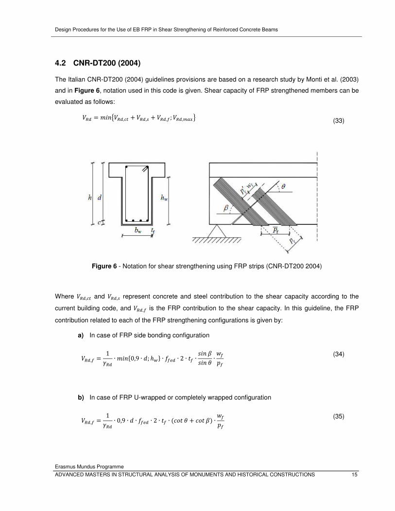
The Italian CNR-DT200 (2004) guidelines provisions are based on a research study by Monti et al. (2003)
and in Figure 6, notation used in this code is given. Shear capacity of FRP strengthened members can be
evaluated as follows:
��� = 9:;<���,�� + ���,� + ���,�; ���,� �> (33)
Figure 6 - Notation for shear strengthening using FRP strips (CNR-DT200 2004)
Where ���,�� and ���,� represent concrete and steel contribution to the shear capacity according to the
current building code, and ���,� is the FRP contribution to the shear capacity. In this guideline, the FRP
contribution related to each of the FRP strengthening configurations is given by:
a) In case of FRP side bonding configuration
���,� = 1Z�� ∙ 9:;l0,9 ∙ '; ℎ"n ∙ *��� ∙ 2 ∙ �� ∙ O:; QO:; ∙ o�p� (34)
b) In case of FRP U-wrapped or completely wrapped configuration
���,� = 1Z�� ∙ 0,9 ∙ ' ∙ *��� ∙ 2 ∙ �� ∙ (��� + ��� Q) ∙ o�p� (35)

Design Procedures for the Use of EB FRP in Shear Strengthening of Reinforced Concrete Beams
Erasmus Mundus Programme
16 ADVANCED MASTERS IN STRUCTURAL ANALYSIS OF MONUMENTS AND HISTORICAL CONSTRUCTIONS
Where the partial factor is assumed to be Z�� = 1,20, d is the member effective depth, ℎ" is the
crossection depth, *��� is the effective FRP design strength, �� is the thickness of the adopted FRP
system, β is the fibers angle with respect to the member longitudinal axis, θ represents the angle of shear
cracks (to be assumed equal to 45° unless a more detailed calculation is made), and o� and p� are FRP
width and spacing, respectively, measured orthogonally to the fiber direction. For FRP strips installed one
next to each other, the ratio o� / p� shall be set equal to 1.0.
Effective FRP design strength:
a) FRP side bonding
*��� = *��� ∙ q�G�,�r9:;l0,9 ∙ '; ℎ"n d1 − 0,6 ∙ J s�rq�G�,�reN (36)
q�G�,�r = q�G� + l�r (37)
q�G� = 9:;l0,9 ∙ '; ℎ"n − l� ∙ sin Q (38)
l�r = O�*���/b� ∙ sin Q (39)
b) U-wrap configurations
*��� = *��� ∙ u1 − 13 ∙ l� ∙ sin Q9:;l0,9 ∙ '; ℎ"nv (40)
c) Completely wrapped members
*��� = *��� ∙ u1 − 16 ∙ l� ∙ sin Q9:;l0,9 ∙ '; ℎ"nv + 12 ∙ (w� ∙ *�� − *���) ∙ u1 − l� ∙ sin Q9:;l0,9 ∙ '; ℎ"nv (41)
w� = 0,2 + 1,6 ∙ x�$" (42)
Design Procedures for the Use of EB FRP in Shear Strengthening of Reinforced Concrete Beams
Erasmus Mundus Programme
ADVANCED MASTERS IN STRUCTURAL ANALYSIS OF MONUMENTS AND HISTORICAL CONSTRUCTIONS 17
0 ≤ x�$" ≤ 0,5 (43)
Where x� is the corner radius of the section to be wrapped, and $" is the width of the member. The second
term of equation (41) shall be considered only when it is greater than zero. The optimal bonded length le,
may be estimated as follows:
s� = J b� ∙ ��2 ∙ *��� (44)
Where b� and �� are Young modulus of elasticity and thickness of FRP, respectively, and *��� is the
average tensile strength of the concrete.
The specific fracture energy Γz1, of the FRP – concrete interface may be expressed as follows (forces in
[N], lengths in [mm]):
Γz1 = 0,03 ∙ A{T*�1 ∙ *��� (45)
Where *�1 is the characteristic strength of concrete, A{ is a geometric coefficient depending on both width
of the strengthened beam $ and width of the FRP system $�; and A{ can be written as follows:
A{ = | 2 − $�$1 + $�400 (46)
Where $�/$ ≥ 0.33 (if $�/$ < 0.33, the value for kb corresponding to {�{ = 0.33 is adopted). For
laminate/sheet end debonding it is assumed that the provided bond length is equal to or larger than the
optimal bonded length, the ultimate design strength *��� can be calculated as follows:
*��� = 1Z�,� ∙ TZ� J2 ∙ b� ∙ Γz1�� (47)

Design Procedures for the Use of EB FRP in Shear Strengthening of Reinforced Concrete Beams
Erasmus Mundus Programme
18 ADVANCED MASTERS IN STRUCTURAL ANALYSIS OF MONUMENTS AND HISTORICAL CONSTRUCTIONS
Where the partial factor is Z�,� = 1,20 (for FRP debonding failure mode and strengthening system with
certification of each component as well as the final product to be applied to a given support) and Z� = 1,5
(partial factor for concrete).
For external FRP reinforcement in the form of discrete strips, strips width, wf (mm), and center-
to-center spacing between strips, pf (mm), shall not exceed the following limitations, respectively:
50 mm ≤ wf ≤ 250 mm, and wf ≤ pf ≤ min{0.5 ⋅ d,3 ⋅ wf ,wf + 200 mm}.
4.3 ACI 440.2R (2008)
The American Concrete Institute (American Concrete Institute (ACI) Committee 440 2008) guideline is
based on a research study by Khalifa (1998). In the ACI code, the total shear strength can be calibrated
as:
�� = �� + �� + ���� (48)
Where �� is the reduction factor, and has value 0,95 for completely wrapped configuration and value 0,85
for three and two-opposite side schemes.
While contributions of steel �� and concrete ��, can be calculated using the current code for
nonstrengthened structures, the FRP contribution is given by:
�� = K�V ∙ *�� ∙ (sin ! + cos !) ∙ '�O� (49)
While:
K�V = 2 ∙ ; ∙ �� ∙ o� (50)
*�� = a�� ∙ b��� = K�V ∙ *�� ∙ (O:; ! + ��O !) ∙ '�O� (51)
Design Procedures for the Use of EB FRP in Shear Strengthening of Reinforced Concrete Beams
Erasmus Mundus Programme
ADVANCED MASTERS IN STRUCTURAL ANALYSIS OF MONUMENTS AND HISTORICAL CONSTRUCTIONS 19
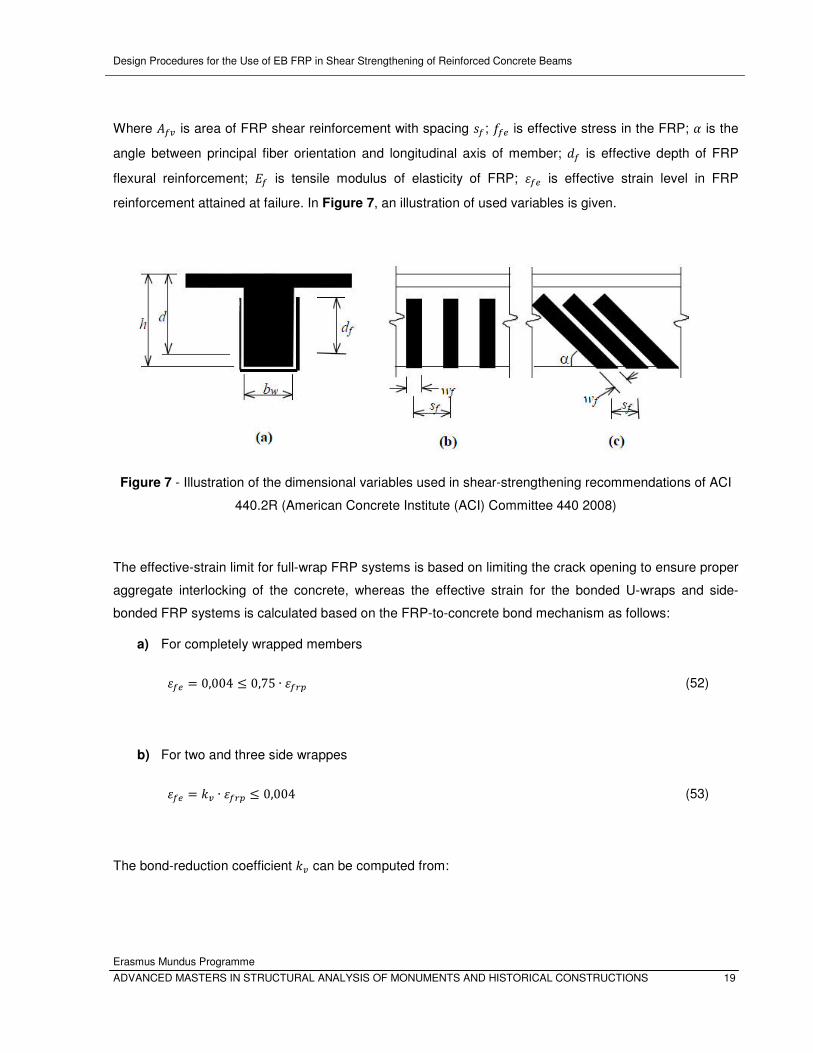
Where K�V is area of FRP shear reinforcement with spacing O�; *�� is effective stress in the FRP; ! is the
angle between principal fiber orientation and longitudinal axis of member; '� is effective depth of FRP
flexural reinforcement; b� is tensile modulus of elasticity of FRP; a�� is effective strain level in FRP
reinforcement attained at failure. In Figure 7, an illustration of used variables is given.
Figure 7 - Illustration of the dimensional variables used in shear-strengthening recommendations of ACI
440.2R (American Concrete Institute (ACI) Committee 440 2008)
The effective-strain limit for full-wrap FRP systems is based on limiting the crack opening to ensure proper
aggregate interlocking of the concrete, whereas the effective strain for the bonded U-wraps and side-
bonded FRP systems is calculated based on the FRP-to-concrete bond mechanism as follows:
a) For completely wrapped members
a�� = 0,004 ≤ 0,75 ∙ a��� (52)
b) For two and three side wrappes
a�� = AV ∙ a��� ≤ 0,004 (53)
The bond-reduction coefficient AV can be computed from:
Design Procedures for the Use of EB FRP in Shear Strengthening of Reinforced Concrete Beams
Erasmus Mundus Programme
20 ADVANCED MASTERS IN STRUCTURAL ANALYSIS OF MONUMENTS AND HISTORICAL CONSTRUCTIONS
AV = A) ∙ AN ∙ �� 11900 ∙ a��� ≤ 0,75 (54)
�� = 23300 H; ∙ �� ∙ b�If,h� ≤ 0,75 (55)
A) = [*�� 27\N CD (56)
For U-wraps:
AN = '�V − �� '�V (57)
For two sides bonded:
AN = '�V − 2�� '�V (58)
As it can be observed from equation (49), ACI uses 45°- truss-angle analogy without variation of the
shear crack angle �x. And the shear strength provided by the FRP reinforcement is determined by
calculating the force resulting from the tensile stress in the FRP across the assumed crack.
4.4 fib ’09 - draft 2009
In this draft of new fib ’09 code for strengthened structures, side-wrapped section are allowed only for
near surface melted (NSM) reinforcement.
The shear capacity of a beam without shear reinforcement is calculated according to the formula:
��� = 9:;<���,� + ��; ���,� �> (59)
Where ���,� is determined according to paragraph 6.2.2 in (Eurocode, 2004). It is here suggested that a
crack angle of 45 ° is used.
Design Procedures for the Use of EB FRP in Shear Strengthening of Reinforced Concrete Beams
Erasmus Mundus Programme
ADVANCED MASTERS IN STRUCTURAL ANALYSIS OF MONUMENTS AND HISTORICAL CONSTRUCTIONS 21
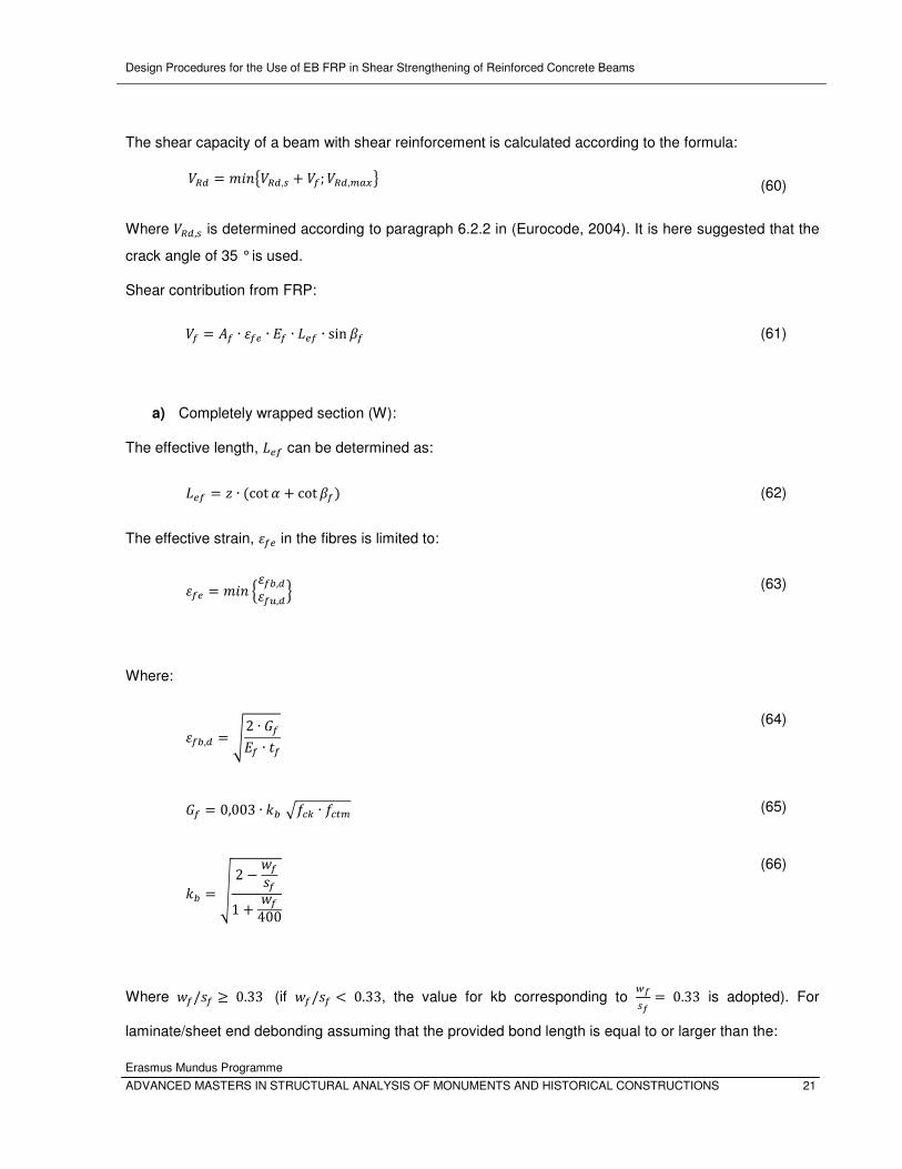
The shear capacity of a beam with shear reinforcement is calculated according to the formula:
��� = 9:;<���,� + ��; ���,� �> (60)
Where ���,� is determined according to paragraph 6.2.2 in (Eurocode, 2004). It is here suggested that the
crack angle of 35 ° is used.
Shear contribution from FRP:
�� = K� ∙ a�� ∙ b� ∙ ��� ∙ sin Q� (61)
a) Completely wrapped section (W):
The effective length, ��� can be determined as:
��� = q ∙ (cot ! + cot Q�) (62)
The effective strain, a�� in the fibres is limited to:
a�� = 9:; �a�{,�a�c,�� (63)
Where:
a�{,� = J 2 ∙ ��b� ∙ �� (64)
�� = 0,003 ∙ A{ T*�1 ∙ *��� (65)
A{ = | 2 − o�O�1 + o�400 (66)
Where o�/O� ≥ 0.33 (if o�/O� < 0.33, the value for kb corresponding to "��� = 0.33 is adopted). For
laminate/sheet end debonding assuming that the provided bond length is equal to or larger than the:
Design Procedures for the Use of EB FRP in Shear Strengthening of Reinforced Concrete Beams
Erasmus Mundus Programme
22 ADVANCED MASTERS IN STRUCTURAL ANALYSIS OF MONUMENTS AND HISTORICAL CONSTRUCTIONS
a�c,� = a�c/Z� (67)
b) U-wrapped section:
��� = '�� ∙ (cot ! + cot Q�) (68)
'�� = 9:; � q'� − s��� (69)
'�� = J b� ∙ ��2 ∙ *��� (70)
Although fib ’09 – draft (2009) is based on equations of Eurocode 2 as basic code, for the purpose of this
research, it is also combined with fib MC10 (2010) as the other models for strengthened structures.
Design Procedures for the Use of EB FRP in Shear Strengthening of Reinforced Concrete Beams
Erasmus Mundus Programme
ADVANCED MASTERS IN STRUCTURAL ANALYSIS OF MONUMENTS AND HISTORICAL CONSTRUCTIONS 23
5. RECENT DESIGN MODEL PROPOSALS
In order to understand better the interaction between internal transverse steel and external FRP
reinforcement and the effect of these two components on concrete-cracking patterns and influence of
crack angle, a brief review of recent design proposals was made. They were used for comparison with
data obtained by following current guidelines recommendation and as result, their deficiencies are
highlighted.
The researchers define the contribution of the FRP to the shear strength as the product between the
effective stress in FRP, the area of the FRP, partial reduction factors that intend to take into account the
quality of material and/or workmanship quality, and a geometrical factor depending on the type of
strengthening system used, as well as fiber inclination with respect to the beams longitudinal axis. In
general, the scientists are in agreement about the type and relevance that these parameters have in the
prediction performance of a model, but the way that these parameters are defined is not the same, and in
general, important differences can be found. The main difference appears in the evaluation of the
stresses/strains in fibers.
In a previous work, several scientists (Barros, Dias and Lima 2007) (Sas, et al. 2009) (Gonzales 2010)
based on the results of the same database, had already verified that none of the analytical formulations
predicts with enough accuracy the contribution of the FRP systems for the shear strengthening of RC
beams. In the present work this type of appraisal is extended to a larger set of models, recently published
in reputed journals and conference proceedings.
The models presented in this section are used to calculate the contribution of the FRP only for the
strengthening configurations for which they were devised. It should be remembered that proposed models
do not give any recommendations for RC members strengthened with a full-wrap configuration.
For the sake of relevancy, all the equations are presented using the same notation as in the original
formulation. A detailed notation list is added after every equation individually.
5.1 Chen and Teng (2003a)
An extensive work performed by Chen and Teng resulted in one of the most widely used shear models.
The general design equation (71) is based on the truss model theory, with the remark that discrete FRP
strips were modeled as equivalent continuous FRP sheets/plates and a reduction factor for the stress is
used instead of strain, as in the other models. Since the writers of the model considered continuous
sheets as a special case of strips, proposed equations are established in terms of strips.
Design Procedures for the Use of EB FRP in Shear Strengthening of Reinforced Concrete Beams
Erasmus Mundus Programme
24 ADVANCED MASTERS IN STRUCTURAL ANALYSIS OF MONUMENTS AND HISTORICAL CONSTRUCTIONS
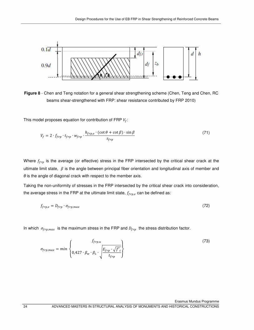
Figure 8 - Chen and Teng notation for a general shear strengthening scheme (Chen, Teng and Chen, RC
beams shear-strengthened with FRP: shear resistance contributed by FRP 2010)
This model proposes equation for contribution of FRP ��:
�� = 2 ∙ *��� ∙ ���� ∙ o��� ∙ ℎ���,� ∙ (cot + cot Q) ∙ sin QO��� (71)
Where *��� is the average (or effective) stress in the FRP intersected by the critical shear crack at the
ultimate limit state, Q is the angle between principal fiber orientation and longitudinal axis of member and
θ is the angle of diagonal crack with respect to the member axis.
Taking the non-uniformity of stresses in the FRP intersected by the critical shear crack into consideration,
the average stress in the FRP at the ultimate limit state, *���,� can be defined as:
*���,� = ���� ∙ E���,� � (72)
In which E���,� � is the maximum stress in the FRP and ���� the stress distribution factor.
E���,� � = 9:; ��� *���,c
0,427 ∙ Q" ∙ Q� ∙ Jb��� ∙ T*′����� ��� (73)
Design Procedures for the Use of EB FRP in Shear Strengthening of Reinforced Concrete Beams
Erasmus Mundus Programme
ADVANCED MASTERS IN STRUCTURAL ANALYSIS OF MONUMENTS AND HISTORICAL CONSTRUCTIONS 25
�� � = �����ℎ���,�sin Q *�x � − �5�A��Oℎ���,�2 sin Q *�x O:'� ps5��O���
�� (74)
The effective height of the FRP ℎ���,� is expressed as:
ℎ���,� = q{ − q� (75)
Where q� and q{ are the coordinates of the top and bottom ends of the effective FRP, which may be
expressed as:
q� = '���,� (76)
q{ = 0,9 ∙ ' − (ℎ − '���) (77)
In which '���,� is the distance from the compression face to the top edge of the FRP, h is the height of the
beam, and '��� is the distance from the compression face to the lower edge of the FRP (thus, '���,� = ℎ
for U jackets). The lower end of the effective FRP is taken to be at the centroid of the steel tension
reinforcement if the FRP terminates at the base of the RC beam (ℎ = '��� in Eq. (77)) for simplification of
expressions. This means that the effective lower end is (h-d) above the actual lower edge of FRP. For
consistency, the lower end of the effective FRP is also taken to be (h-d) above the actual lower edge if the
FRP terminates above the base. This treatment is again conservative.
Q� = � 1 :* S ≥ 1sin �S2 :* S < 1� (78)
S = �� ��� (79)

Design Procedures for the Use of EB FRP in Shear Strengthening of Reinforced Concrete Beams
Erasmus Mundus Programme
26 ADVANCED MASTERS IN STRUCTURAL ANALYSIS OF MONUMENTS AND HISTORICAL CONSTRUCTIONS
�� = Jb��� ∙ ����T*′� (80)
q{ = Q" = J2 − o�/HO� ∙ sin QI1 + o�/HO� ∙ sin QI 0,9 ∙ ' − (ℎ − '���) (81)
Although reviewed by authors Chen and Teng in 2010 (RC beams shear-strengthened with FRP: shear
resistance contributed by FRP) and compared with modified model, it was concluded by themselves that
the original model of Chen and Teng (2003a) is more suitable for the use in design considering its overall
accuracy and simpler form.
5.2 Carolin and Täljsten (2005)
Figure 9 - Fiber alignment and crack angle, Carolin and Taljsten (2005)
The design model is based on the superposition principle of the shear contributions of the strengthening
and the strut and tie model.
Contribution of FRP strengthening to total shear strength, �� has been suggested by Carolin and Täljsten
as:
�� = � ∙ a� ∙ b� ∙ �� ∙ q ∙ (cos sin !) ∙ sin Q (82)
Where � is a reduction factor that considers linear elastic material (� = 0,6), a� is critical strain in fibers, b�
is modulus of elasticity of fibres, �� is thickness of fibres, and q is the length of a vertical tension tie in the

Design Procedures for the Use of EB FRP in Shear Strengthening of Reinforced Concrete Beams
Erasmus Mundus Programme
ADVANCED MASTERS IN STRUCTURAL ANALYSIS OF MONUMENTS AND HISTORICAL CONSTRUCTIONS 27
truss, for steel stirrups normally expressed by the internal lever arm or 0.9d. The variables !, Q and are
angles considering crack inclination, fiber direction and the difference between them, respectively.
5.3 Pellegrino and Modena (2008)
Based on their own and experimental results of other investigations on the interaction between an external
FRP and an internal transverse steel reinforcement, Pellegrino and Modena proposed a new analytical
model. This model describes the shear capacity of RC beams strengthened according to the most
common schemes, taking into account interaction between FRP and transversal steel.
Figure 10 - Shape of the fracture surface of “U-jacketed” (a) and side-bonded beams (b)
They assumed the external FRP strains equal to those of internal stirrups, and obtained the FRP shear
contribution �� from the rotational equilibrium of the forces �� and �� operating in the FRP and concrete
surface respectively, at failure (Figure 11):
�� = 2 ∙ ;� ∙ �� ∙ �� ∙ o� ∙ a�� ∙ b� ∙ ℎ�O� (83)
Where ;� is the number of layers, �� is the thickness of FRP (one layer), o� is the width of FRP, b� is the
elastic modulus of FRP in the principal fiber orientation, ℎ� is the vertical distance from the top edge of the
FRP shear reinforcement to the bottom of concrete crossection, O� is the spacing of FRP strips and a�� is
effective strain:
a�� = 2 ∙ *�� ∙ K� ∙ cosN w ∙ $�,V;� ∙ �� ∙ �� ∙ b� ∙ ℎ� − s�ℎ� ∙ $� (84)
Design Procedures for the Use of EB FRP in Shear Strengthening of Reinforced Concrete Beams
Erasmus Mundus Programme
28 ADVANCED MASTERS IN STRUCTURAL ANALYSIS OF MONUMENTS AND HISTORICAL CONSTRUCTIONS
Where w is the angle characterizing the conventional roughness of the interface, which is by these authors
assumed to be equal to 79°, according to the calibration process based on the experimental ultimate
shear capacities.
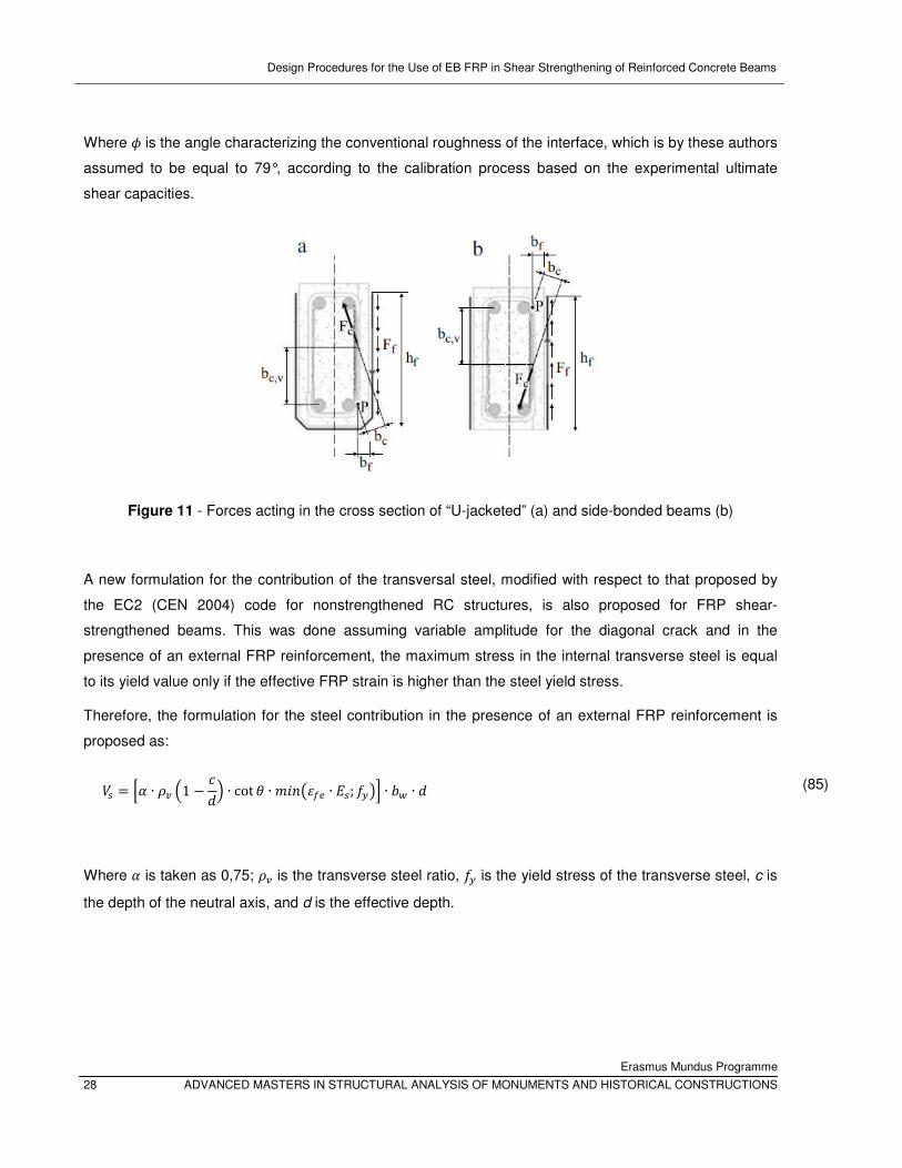
Figure 11 - Forces acting in the cross section of “U-jacketed” (a) and side-bonded beams (b)
A new formulation for the contribution of the transversal steel, modified with respect to that proposed by
the EC2 (CEN 2004) code for nonstrengthened RC structures, is also proposed for FRP shear-
strengthened beams. This was done assuming variable amplitude for the diagonal crack and in the
presence of an external FRP reinforcement, the maximum stress in the internal transverse steel is equal
to its yield value only if the effective FRP strain is higher than the steel yield stress.
Therefore, the formulation for the steel contribution in the presence of an external FRP reinforcement is
proposed as:
�� = ?! ∙ BV �1 − �'� ∙ cot ∙ 9:;Ha�� ∙ b�; *PIF ∙ $" ∙ ' (85)
Where ! is taken as 0,75; BV is the transverse steel ratio, *P is the yield stress of the transverse steel, c is
the depth of the neutral axis, and d is the effective depth.
Design Procedures for the Use of EB FRP in Shear Strengthening of Reinforced Concrete Beams
Erasmus Mundus Programme
ADVANCED MASTERS IN STRUCTURAL ANALYSIS OF MONUMENTS AND HISTORICAL CONSTRUCTIONS 29
5.4 Bukhari et al. (2010)
A group of authors is proposing shear strength of beams without internal stirrups strengthened with FRP
only, ���,z�� as:
���,z�� = @ ∙ q� ∙ $" ∙ b� ∙ (cot + cot Q) ∙ sin Q (86)
� = 9:;�B ∙ a��,) ; B∗ ∙ a��,N� (87)
a) For side wrap:
a��,) = 0,7 ∙ �40,25 B ∙ b�/*�N CD ¡jf,¢£ ∙ 10jC ≤ 0,1 ∙ a�c ≤ 0,004 (88)
b) For U wrap:
a��,) = 0,8 ∙ �29,14 B ∙ b�/*�N CD ¡jf,¤�£ ∙ 10jC ≤ 0,1 ∙ a�c ≤ 0,004 (89)
And:
a��,N = 9:; ¥a�c2 ; 0,64 ∙ J *��b�� ∙ �� ; 0,004¦ (90)
B�∗ = B� ∙ H'� − ; ∙ s�� �/3I/q� (91)
Where B� is FRP shear reinforcement ratio, n=0 for fully wrapped sections, 1 for U wrap and 2 for side
wrap, q� = 0,9'� and s�� � is the anchorage length required to develop full anchorage capacity which is
taken as:
s�� � = 0,7 ∙ Jb� ∙ ��*��� (92)
Design Procedures for the Use of EB FRP in Shear Strengthening of Reinforced Concrete Beams
Erasmus Mundus Programme
30 ADVANCED MASTERS IN STRUCTURAL ANALYSIS OF MONUMENTS AND HISTORICAL CONSTRUCTIONS
5.5 Modifi and Chaallal (2011)
A new design approach has been proposed for calculating the shear contribution of FRP by these two
authors, taking into account the effect of transverse steel on the EB FRP contribution in shear. They
proposed equation for contribution of FRP ( ��), taking into account a variable crack angle:
�� = BV ∙ b� ∙ a�� ∙ $ ∙ '� ∙ (cot + cot !) ∙ sin ! (93)
Where BV is FRP shear reinforcement ratio, b� is the elastic modulus of FRP in the principal fiber
orientation, $ is cross section width, '� is FRP effective depth ! is the angle between principal fiber
orientation and longitudinal axis of member and θ is the angle of diagonal crack with respect to the
member axis.
It should be noted that in the case of a continuous FRP sheet, the FRP width, wf, and the spacing, sf, can
be assumed equal to 1. The effective strain, a�� can be calculatted using formulation:
a�� = 0,31 ∙ Q� ∙ Q� ∙ Q" ∙ J T*′��� ∙ b� ≤ ac� (94)
Where *′� is compressive strength of concrete, and coefficient Q� (cracking modification factor) is:
a) For U-jackets:
Q� = 0,6TB� ∙ b� + B� ∙ b�
b) For side bonded FRP:
Q� = 0,43TB� ∙ b� + B� ∙ b� (95)
Where Q� is a decreasing coefficient (FRP effective anchorage length ratio) which represent the effect of
FRP sheets having an anchorage length shorter than �� and it is Q� = 1 for S ≥ 1 or Q� = (2 − S) ∙ S for S < 1. While:
Design Procedures for the Use of EB FRP in Shear Strengthening of Reinforced Concrete Beams
Erasmus Mundus Programme
ADVANCED MASTERS IN STRUCTURAL ANALYSIS OF MONUMENTS AND HISTORICAL CONSTRUCTIONS 31
S = �� ��� (96)
�� � is the maximum available bond length, calculated as '�/ sin ! for U-jackets or 2 ∙ '�/ sin ! for side
plates. And �� is effective bond length in mm, calculated as:
�� = Jb� ∙ ��2 ∙ *�� (97)
Q" = J2 − o�/O�1 + o�/O� (98)

Design Procedures for the Use of EB FRP in Shear Strengthening of Reinforced Concrete Beams
Erasmus Mundus Programme
32 ADVANCED MASTERS IN STRUCTURAL ANALYSIS OF MONUMENTS AND HISTORICAL CONSTRUCTIONS
Design Procedures for the Use of EB FRP in Shear Strengthening of Reinforced Concrete Beams
Erasmus Mundus Programme
ADVANCED MASTERS IN STRUCTURAL ANALYSIS OF MONUMENTS AND HISTORICAL CONSTRUCTIONS 33
6. METHODOLOGY FOR ANALYZING EXPERIMENTAL VS THEORETICAL
VALUES
In this chapter, the general methodology that will be used in this study for comparison between the
experimental values of different test carried out on concrete beams strengthened by FRP and the values
predicted by the equations of the studied codes and recently proposed models is presented.
Firstly, evaluation of the codes and models is made using the total database improved during the
execution of this document. Later on, evaluation of best predictions is made using reduced database,
considering only U-jacketed configuration with transversal steel. Total value of the theoretical shear
strength (concrete, steel and FRP contribution) is compared, distinguishing the presence of transversal
steel reinforcement and the type of strengthened scheme used in the tested specimens.
It should be pointed out that all formulations used in analysis of data base, both from guidelines
and recent models are treated without partial factors of safety in order to gain representative theoretical
values, comparable with testing results.
6.1 Database Description
The use of databases (DBs) with modern statistical analysis and data-mining software packages provides
the basis for registering, sharing and manipulating results from a large number of experimental tests
performed worldwide by different researchers. This kind of approach, used in the present work, is
particularly suitable for the study of complex phenomena (such as the shear behaviour of RC beams
strengthened with FRP) in which the number of variables involved is large and their relative importance is
not yet known.
Relevant data was collected from experimental programs carried out in recent years in the context of
shear strengthening with FRP, and an extended database was obtained. Using this data, the performance
of different design guidelines was appraised by means of comparing the behaviour of the FRP shear
systems predicted by analytical formulations with those registered experimentally.
To assess the accuracy of the theoretical predictions obtained with analytical formulations, presented in
chapters 3 and 4, a DB containing 225 experimental results of RC beams strengthened with externally
bonded FRP was collected from published literature, and previously compiled DBs (Sas, et al. 2009)
(Gonzales 2010) were upgraded. Afterwards, a reduced data base (RDB) was obtained, keeping only
results from U-jacketed configurations with transversal steel, since this is the most used case in practical
application of FRP strengthening systems.
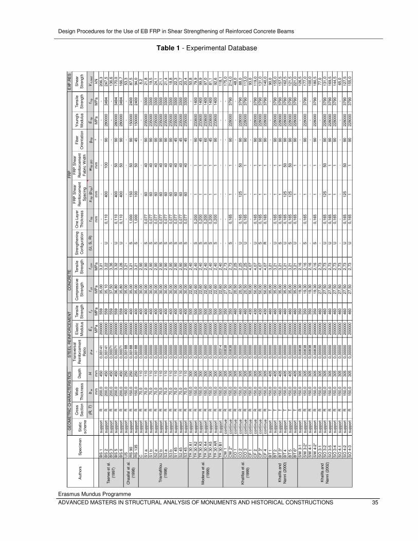
The database (Table 2 to 5) contains values from experiments performed on 30 beams with T cross
sections and 194 beams with rectangular cross sections. For calculating the predictions of each individual
Design Procedures for the Use of EB FRP in Shear Strengthening of Reinforced Concrete Beams
Erasmus Mundus Programme
34 ADVANCED MASTERS IN STRUCTURAL ANALYSIS OF MONUMENTS AND HISTORICAL CONSTRUCTIONS
model, the material properties obtained from tests and reported in the original papers have been
considered. No partial safety factors have been adopted in the calculations of the predictions.
The database was divided in groups in order to study the accuracy of the codes for different strengthening
schemes. DB contains data of 36 and 27 tested U-jacketed configurations with and without transversal
steel, respectively. Tested side bonded configurations with transversal steel are 49, while without
transversal reinforcement are 16. Fully wrapped configurations are 22 in DB, and the rest of data are
‘’control samples’’ without FRP reinforcement, which are 69 in this DB. Total number of tests in RDB is 27.
In all beams with transversal reinforcement, inclination of the stirrups relative to the beam axis is 90°.
Design Procedures for the Use of EB FRP in Shear Strengthening of Reinforced Concrete Beams
Erasmus Mundus Programme
ADVANCED MASTERS IN STRUCTURAL ANALYSIS OF MONUMENTS AND HISTORICAL CONSTRUCTIONS 35
Cro
ss
Sec
tion
Web
Th
ickn
ess
Dep
thTr
ansv
ersa
l R
einf
orce
men
t R
atio
Ela
stic
M
odul
usTe
nsile
S
tren
gth
Com
pres
sive
S
tren
gth
Tens
ile
Str
engt
hS
tren
gthe
ning
C
onfig
urat
ion
One
Lay
er
Thic
knes
s
FR
P S
hear
R
einf
orce
men
t S
paci
ng
FR
P S
hear
R
einf
orce
men
t F
abric
Wid
th
Fib
er
Orie
ntat
ion
You
ng's
M
odul
usTe
nsile
S
tren
gth
She
ar
Str
engt
h
(R,
T)
bw
Hρ
wE
sf y
f ck
f ctm
(U,
S,
R)
t frp
sfr
p (
pfr
p)
wfr
p (
bf)
βfr
pE
frp
f frp
Vn
,te
st
mm
mm
-M
Pa
MP
aM
Pa
MP
am
mm
mm
m°
MP
aM
Pa
kNB
S 1
supp
ort
R20
0,0
450
0,00
141
2000
0055
935
,00
3,21
--
--
--
-20
6,3
BS
2su
ppor
tR
200,
045
00,
0014
120
0000
559
35,1
03,
22U
0,11
040
010
090
2800
0034
9424
7,5
BS
3su
ppor
tR
200,
045
00,
0007
120
0000
559
37,5
03,
36-
--
--
--
136,
6B
S 5
supp
ort
R20
0,0
450
0,00
071
2000
0055
936
,80
3,32
U0,
110
400
5090
2800
0034
9417
0,0
BS
6su
ppor
tR
200,
045
00,
0007
120
0000
559
35,8
03,
26U
0,11
040
050
9028
0000
3494
166,
7U
Ssu
ppor
tR
150,
025
00,
0018
820
0000
400
35,0
03,
21-
--
--
--
53,3
RS
90
supp
ort
R15
0,0
250
0,00
188
2000
0040
035
,00
3,21
S1,
000
150
5090
1500
0024
0087
,5R
S 1
35su
ppor
tR
150,
025
00,
0018
820
0000
400
35,0
03,
21S
1,00
010
050
4515
0000
2400
94,0
Csu
ppor
tR
70,0
110
0,00
000
2000
0040
030
,00
2,90
--
--
--
-8,
2S
1 a
supp
ort
R70
,011
00,
0000
020
0000
400
30,0
02,
90S
0,07
760
4090
2350
0033
0021
,8S
1 b
supp
ort
R70
,011
00,
0000
020
0000
400
30,0
02,
90S
0,07
760
4090
2350
0033
0019
,5S
2 a
supp
ort
R70
,011
00,
0000
020
0000
400
30,0
02,
90S
0,07
760
4090
2350
0033
0024
,1S
2 b
supp
ort
R70
,011
00,
0000
020
0000
400
30,0
02,
90S
0,07
760
4090
2350
0033
0021
,1S
3 a
supp
ort
R70
,011
00,
0000
020
0000
400
30,0
02,
90S
0,07
760
4090
2350
0033
0021
,4S
3 b
supp
ort
R70
,011
00,
0000
020
0000
400
30,0
02,
90S
0,07
760
4090
2350
0033
0018
,8S
1 45
supp
ort
R70
,011
00,
0000
020
0000
400
30,0
02,
90S
0,07
760
4045
2350
0033
0022
,3S
2 45
supp
ort
R70
,011
00,
0000
020
0000
400
30,0
02,
90S
0,07
760
4045
2350
0033
0023
,7S
3 45
supp
ort
R70
,011
00,
0000
020
0000
400
30,0
02,
90S
0,07
760
4045
2350
0033
0020
,4TR
30
A1
supp
ort
R15
0,0
300
0,00
000
2000
0050
022
,60
2,40
--
--
--
-50
,8TR
30
A2
supp
ort
R15
0,0
300
0,00
000
2000
0050
022
,60
2,40
S0,
200
11
9023
3600
1400
79,9
TR 3
0 A
3su
ppor
tR
150,
030
00,
0000
020
0000
500
22,6
02,
40S
0,20
01
145
2336
0014
0099
,9TR
30
A4
supp
ort
R15
0,0
300
0,00
000
2000
0050
022
,60
2,40
S0,
200
11
6023
3600
1400
97,0
TR 3
0 A
5su
ppor
tR
150,
030
00,
0000
020
0000
500
22,6
02,
40S
0,20
01
145
2336
0014
0081
,1TR
30
AR
supp
ort
R15
0,0
300
0,00
000
2000
0050
022
,60
2,40
S0,
200
11
9023
3600
1400
92,6
TR 3
0 B
1su
ppor
tR
150,
030
00,
0031
420
0000
500
22,6
02,
40-
--
--
--
118,
1C
W 1
cont
inue
R15
0,0
305
0,00
838
2000
0035
027
,50
2,73
--
--
--
-17
5,0
CW
2*
cont
inue
R15
0,0
305
0,00
838
2000
0035
027
,50
2,73
S0,
165
11
9022
8000
3790
214,
0C
O 1
cont
inue
R15
0,0
305
0,00
000
2000
0046
020
,50
2,25
--
--
--
-48
,0C
O 2
cont
inue
R15
0,0
305
0,00
000
2000
0046
020
,50
2,25
U0,
165
125
5090
2280
0037
9088
,0C
O 3
cont
inue
R15
0,0
305
0,00
000
2000
0046
020
,50
2,25
U0,
165
11
9022
8000
3790
113,
0C
F 1
cont
inue
R15
0,0
305
0,00
000
2000
0043
050
,00
4,07
--
--
--
-93
,0C
F 2
cont
inue
R15
0,0
305
0,00
000
2000
0043
050
,00
4,07
U0,
165
11
9022
8000
3790
119,
0C
F 3
*co
ntin
ueR
150,
030
50,
0000
020
0000
430
50,0
04,
07S
0,16
51
190
2280
0037
9013
1,0
CF
4co
ntin
ueR
150,
030
50,
0000
020
0000
430
50,0
04,
07R
0,16
51
190
2280
0037
9014
0,0
BT
1su
ppor
tT
150,
040
50,
0000
020
0000
460
35,0
03,
21-
--
--
--
90,0
BT
2su
ppor
tT
150,
040
50,
0000
020
0000
460
35,0
03,
21U
0,16
51
190
2280
0037
9015
5,0
BT
3*su
ppor
tT
150,
040
50,
0000
020
0000
460
35,0
03,
21S
0,16
51
190
2280
0037
9015
7,5
BT
4su
ppor
tT
150,
040
50,
0000
020
0000
460
35,0
03,
21U
0,16
512
550
9022
8000
3790
162,
5B
T 5
supp
ort
T15
0,0
405
0,00
000
2000
0046
035
,00
3,21
S0,
165
125
5090
2280
0037
9012
1,5
BT
6*su
ppor
tT
150,
040
50,
0000
020
0000
460
35,0
03,
21U
0,16
51
190
2280
0037
9022
1,0
SW
3-1
supp
ort
R15
0,0
305
0,00
838
2000
0035
019
,30
2,16
--
--
--
-12
6,5
SW
3-2
*su
ppor
tR
150,
030
50,
0083
820
0000
350
19,3
02,
16S
0,16
51
190
2280
0037
9017
7,0
SW
4-1
supp
ort
R15
0,0
305
0,00
838
2000
0035
019
,30
2,16
--
--
--
-10
0,0
SW
4-2
*su
ppor
tR
150,
030
50,
0083
820
0000
350
19,3
02,
16S
0,16
51
190
2280
0037
9018
0,5
SO
3-1
supp
ort
R15
0,0
305
0,00
000
2000
0046
027
,50
2,73
--
--
--
-77
,0S
O 3
-2su
ppor
tR
150,
030
50,
0000
020
0000
460
27,5
02,
73U
0,16
512
550
9022
8000
3790
131,
0S
O 3
-5su
ppor
tR
150,
030
50,
0000
020
0000
460
27,5
02,
73U
0,16
51
190
2280
0037
9016
9,5
SO
3-4
supp
ort
R15
0,0
305
0,00
000
2000
0046
027
,50
2,73
U0,
165
11
9022
8000
3790
144,
5S
O 4
-1su
ppor
tR
150,
030
50,
0000
020
0000
460
27,5
02,
73-
--
--
--
65,0
SO
4-2
supp
ort
R15
0,0
305
0,00
000
2000
0046
027
,50
2,73
U0,
165
125
5090
2280
0037
9012
7,5
SO
4-3
supp
ort
R15
0,0
305
0,00
000
2000
0046
027
,50
2,73
U0,
165
11
9022
8000
3790
155,
0
Kha
lifa
and
Nan
ni (
2000
)
Kha
lifa
and
Nan
ni (
2002
)
STE
EL
RE
INF
OR
CE
ME
NT
Aut
hors
Spe
cim
en
FR
P
Kha
lifaa
et
al.
(199
9)
Cha
alla
l et
al.
(199
8)
Tria
ntaf
illou
(1
998)
GE
OM
ETR
IC C
HA
RA
CTE
RIS
TIC
SE
XP.R
ES
CO
NC
RE
TE
Mod
ena
et a
l. (1
999)
Taer
we
et a
l. (1
997)
Sta
tic
sche
me
Table 1 - Experimental Database
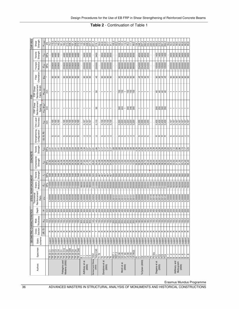
Design Procedures for the Use of EB FRP in Shear Strengthening of Reinforced Concrete Beams
Erasmus Mundus Programme
36 ADVANCED MASTERS IN STRUCTURAL ANALYSIS OF MONUMENTS AND HISTORICAL CONSTRUCTIONS
Cro
ss
Sec
tion
Web
Th
ickn
ess
Dep
thTr
ansv
ersa
l R
einf
orce
men
t R
atio
Ela
stic
M
odul
usTe
nsile
S
tren
gth
Com
pres
sive
S
tren
gth
Tens
ile
Str
engt
hS
tren
gthe
ning
C
onfig
urat
ion
One
Lay
er
Thic
knes
s
FR
P S
hear
R
einf
orce
men
t S
paci
ng
FR
P S
hear
R
einf
orce
men
t F
abric
Wid
th
Fib
er
Orie
ntat
ion
You
ng's
M
odul
usTe
nsile
S
tren
gth
She
ar
Str
engt
h
(R,
T)
bw
Hρ
wE
sf y
f ck
f ctm
(U,
S,
R)
t frp
sfr
p (
pfr
p)
wfr
p (
bf)
βfr
pE
frp
f frp
Vn
,te
st
mm
mm
-M
Pa
MP
aM
Pa
MP
am
mm
mm
m°
MP
aM
Pa
kNTR
30
C1
supp
ort
R15
0,0
300
0,00
000
2100
0054
822
,82
2,41
--
--
--
-74
,7TR
30
C2
supp
ort
R15
0,0
300
0,00
000
2100
0054
822
,82
2,41
S0,
165
11
9023
3600
4490
119,
0TR
30
C3
supp
ort
R15
0,0
300
0,00
000
2100
0054
822
,82
2,41
S0,
165
11
9023
3600
4490
112,
8TR
30
C4
supp
ort
R15
0,0
300
0,00
000
2100
0054
822
,82
2,41
S0,
165
11
9023
3600
4490
140,
0TR
30
D1
supp
ort
R15
0,0
300
0,00
335
2100
0054
826
,06
2,64
--
--
--
-16
1,5
TR 3
0 D
10su
ppor
tR
150,
030
00,
0033
521
0000
548
26,0
62,
64S
0,16
51
190
2336
0044
9019
3,0
TR 3
0 D
2su
ppor
tR
150,
030
00,
0033
521
0000
548
26,0
62,
64S
0,16
51
190
2336
0044
9021
3,3
TR 3
0 D
20su
ppor
tR
150,
030
00,
0033
521
0000
548
26,0
62,
64S
0,16
51
190
2336
0044
9023
8,3
TR 3
0 D
3su
ppor
tR
150,
030
00,
0033
521
0000
548
26,0
62,
64S
0,16
51
190
2336
0044
9016
1,4
TR 3
0 D
4su
ppor
tR
150,
030
00,
0033
521
0000
548
26,0
62,
64S
0,16
51
190
2336
0044
9020
8,8
TR 3
0 D
40su
ppor
tR
150,
030
00,
0033
521
0000
548
26,0
62,
64S
0,16
51
190
2336
0044
9021
2,0
B 1
supp
ort
R30
0,0
300
0,00
000
1960
0039
538
,00
3,39
--
--
--
-11
2,0
C 1
supp
ort
R30
0,0
300
0,00
000
1960
0039
537
,20
3,34
U0,
167
11
9023
0000
3400
165,
0C
2su
ppor
tR
300,
030
00,
0000
019
6000
395
41,0
03,
57U
0,16
71
190
2300
0034
0022
8,5
C 3
supp
ort
R30
0,0
300
0,00
000
1960
0039
541
,10
3,57
U0,
167
11
9023
0000
3400
237,
5T4
S2
supp
ort
T14
0,0
400
0,00
202
2100
0052
028
,60
2,81
--
--
--
-20
1,3
T4S
2-C
45su
ppor
tT
140,
040
00,
0020
221
0000
520
29,4
02,
86U
0,11
050
5045
2300
0034
0021
9,1
T1-T
2su
ppor
tR
150,
020
00,
0000
020
5000
467
34,2
83,
17-
--
--
--
59,9
T3su
ppor
tR
150,
020
00,
0000
020
5000
467
34,2
83,
17S
0,13
01
190
2300
0035
0060
,8T4
supp
ort
R15
0,0
200
0,00
000
2050
0046
734
,28
3,17
S0,
130
11
9023
0000
3500
60,8
T5su
ppor
tR
150,
020
00,
0000
020
5000
467
34,2
83,
17U
0,13
01
190
2300
0035
0097
,7T6
supp
ort
R15
0,0
200
0,00
000
2050
0046
734
,28
3,17
U0,
130
11
9023
0000
3500
91,1
RE
F 1
supp
ort
R25
0,0
450
0,00
101
2000
0050
013
,30
1,68
--
--
--
-10
5,0
RE
F 2
supp
ort
R25
0,0
450
0,00
101
2000
0050
013
,30
1,68
--
--
--
-93
,5S
S 9
0su
ppor
tR
250,
045
00,
0010
120
0000
500
13,3
01,
68S
0,22
030
015
090
3900
0030
0010
2,5
SS
45
supp
ort
R25
0,0
450
0,00
101
2000
0050
013
,30
1,68
S0,
220
424
150
4539
0000
3000
101,
0S
F 9
0su
ppor
tR
250,
045
00,
0010
120
0000
500
13,3
01,
68S
0,22
01
190
3900
0030
0011
2,5
US
90
supp
ort
R25
0,0
450
0,00
101
2000
0050
013
,30
1,68
U0,
220
300
150
9039
0000
3000
95,0
US
60
supp
ort
R25
0,0
450
0,00
101
2000
0050
013
,30
1,68
U0,
220
346
150
6039
0000
3000
111,
0U
S 9
0(2)
supp
ort
R25
0,0
450
0,00
101
2000
0050
013
,30
1,68
U0,
220
300
150
9039
0000
3000
89,5
R1
supp
ort
R18
0,0
500
0,00
000
2050
0050
055
,94
4,39
--
--
--
-12
4,1
C1
supp
ort
R18
0,0
500
0,00
000
2050
0050
055
,94
4,39
S0,
055
11
4523
4000
4500
246,
7C
2su
ppor
tR
180,
050
00,
0000
020
5000
500
59,2
64,
56S
0,05
51
145
2340
0045
0025
7,2
C3
supp
ort
R18
0,0
500
0,00
000
2050
0050
048
,72
4,00
S0,
055
11
9023
4000
4500
260,
6C
5su
ppor
tR
180,
050
00,
0000
020
5000
500
59,2
64,
56S
0,05
51
145
2340
0045
0033
4,3
P0
supp
ort
R13
0,0
450
0,00
145
2100
0055
038
,00
3,39
--
--
--
-22
0,0
P0-
bis
supp
ort
R13
0,0
450
0,00
145
2100
0055
038
,00
3,39
--
--
--
-22
0,0
PC
1su
ppor
tR
130,
045
00,
0014
521
0000
550
38,0
03,
39R
0,43
020
040
9010
5000
1400
355,
0P
C2
supp
ort
R13
0,0
450
0,00
145
2100
0055
038
,00
3,39
R0,
430
250
4090
1050
0014
0031
0,0
PC
3su
ppor
tR
130,
045
00,
0014
521
0000
550
38,0
03,
39R
0,43
030
040
4510
5000
1400
291,
0P
C4
supp
ort
R13
0,0
450
0,00
145
2100
0055
038
,00
3,39
R0,
430
350
4045
1050
0014
0026
4,0
B -
1su
ppor
tR
150,
020
00,
0000
018
2000
582
30,5
02,
93-
--
--
--
39,2
B -
2su
ppor
tR
150,
020
00,
0000
018
2000
582
35,4
03,
23S
0,16
71
190
2300
0034
0050
,5B
- 3
supp
ort
R15
0,0
200
0,00
000
1820
0058
233
,50
3,12
S0,
167
11
9023
0000
3400
63,6
B -
4su
ppor
tR
150,
020
00,
0000
018
2000
582
31,5
02,
99S
0,16
71
190
2300
0034
0058
,6B
- 5
supp
ort
R15
0,0
200
0,00
000
1820
0058
231
,00
2,96
S0,
167
11
9023
0000
3400
60,3
B -
6su
ppor
tR
150,
020
00,
0000
018
2000
582
33,7
03,
13S
0,16
71
190
2300
0034
0080
,8B
- 7
supp
ort
R15
0,0
200
0,00
000
1820
0058
234
,40
3,17
U0,
167
11
9023
0000
3400
68,5
B -
8su
ppor
tR
150,
020
00,
0000
018
2000
582
35,4
03,
23U
0,16
71
190
2300
0034
0085
,8
CO
NC
RE
TEF
RP
EXP
.RE
S
Sta
tic
sche
me
Aut
hors
Dia
gana
et
al.
(200
3)
Adh
ikar
y an
d M
utsu
yosh
i (2
004)
Ta¨lj
sten
(20
03)
Pel
legr
ino
and
Mod
ena
(200
2)
Mon
ti et
al.
(200
3)
Spe
cim
en
Don
aton
e et
al.
(200
3)
Den
iaud
and
Che
ng
(200
3)
GE
OM
ETR
IC C
HA
RA
CTE
RIS
TIC
SS
TEE
L R
EIN
FO
RC
EM
EN
T
Adh
ikar
y et
al.
(200
3)
Table 2 - Continuation of Table 1
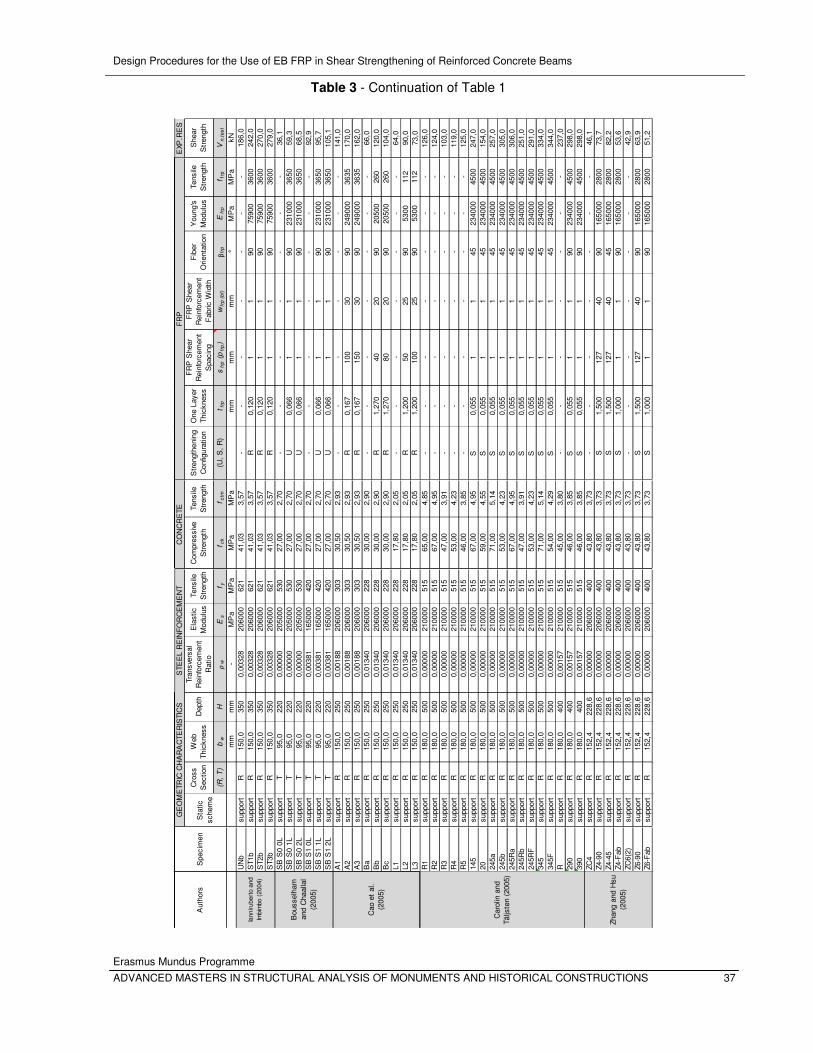
Design Procedures for the Use of EB FRP in Shear Strengthening of Reinforced Concrete Beams
Erasmus Mundus Programme
ADVANCED MASTERS IN STRUCTURAL ANALYSIS OF MONUMENTS AND HISTORICAL CONSTRUCTIONS 37
Cro
ss
Sec
tion
Web
Th
ickn
ess
Dep
thTr
ansv
ersa
l R
einf
orce
men
t R
atio
Ela
stic
M
odul
usTe
nsile
S
tren
gth
Com
pres
sive
S
tren
gth
Tens
ile
Str
engt
hS
tren
gthe
ning
C
onfig
urat
ion
One
Lay
er
Thic
knes
s
FR
P S
hear
R
einf
orce
men
t S
paci
ng
FR
P S
hear
R
einf
orce
men
t F
abric
Wid
th
Fib
er
Orie
ntat
ion
You
ng's
M
odul
usTe
nsile
S
tren
gth
She
ar
Str
engt
h
(R,
T)
bw
Hρ
wE
sf y
f ck
f ctm
(U,
S,
R)
t frp
sfr
p (
pfr
p)
wfr
p (
bf)
βfr
pE
frp
f frp
Vn
,te
st
mm
mm
-M
Pa
MP
aM
Pa
MP
am
mm
mm
m°
MP
aM
Pa
kNU
Nb
supp
ort
R15
0,0
350
0,00
328
2060
0062
141
,03
3,57
--
--
--
-18
6,0
ST1
bsu
ppor
tR
150,
035
00,
0032
820
6000
621
41,0
33,
57R
0,12
01
190
7590
036
0024
2,0
ST2
bsu
ppor
tR
150,
035
00,
0032
820
6000
621
41,0
33,
57R
0,12
01
190
7590
036
0027
0,0
ST3
bsu
ppor
tR
150,
035
00,
0032
820
6000
621
41,0
33,
57R
0,12
01
190
7590
036
0027
9,0
SB
S0
0Lsu
ppor
tT
95,0
220
0,00
000
2050
0053
027
,00
2,70
--
--
--
-36
,1S
B S
0 1L
supp
ort
T95
,022
00,
0000
020
5000
530
27,0
02,
70U
0,06
61
190
2310
0036
5059
,3S
B S
0 2L
supp
ort
T95
,022
00,
0000
020
5000
530
27,0
02,
70U
0,06
61
190
2310
0036
5068
,5S
B S
1 0L
supp
ort
T95
,022
00,
0038
116
5000
420
27,0
02,
70-
--
--
--
92,9
SB
S1
1Lsu
ppor
tT
95,0
220
0,00
381
1650
0042
027
,00
2,70
U0,
066
11
9023
1000
3650
95,7
SB
S1
2Lsu
ppor
tT
95,0
220
0,00
381
1650
0042
027
,00
2,70
U0,
066
11
9023
1000
3650
105,
1A
1su
ppor
tR
150,
025
00,
0018
820
6000
303
30,5
02,
93-
--
--
--
141,
0A
2su
ppor
tR
150,
025
00,
0018
820
6000
303
30,5
02,
93R
0,16
710
030
9024
9000
3635
170,
0A
3su
ppor
tR
150,
025
00,
0018
820
6000
303
30,5
02,
93R
0,16
715
030
9024
9000
3635
162,
0B
asu
ppor
tR
150,
025
00,
0134
020
6000
228
30,0
02,
90-
--
--
--
66,0
Bb
supp
ort
R15
0,0
250
0,01
340
2060
0022
830
,00
2,90
R1,
270
4020
9020
500
260
120,
0B
csu
ppor
tR
150,
025
00,
0134
020
6000
228
30,0
02,
90R
1,27
080
2090
2050
026
010
4,0
L1su
ppor
tR
150,
025
00,
0134
020
6000
228
17,8
02,
05-
--
--
--
64,0
L2su
ppor
tR
150,
025
00,
0134
020
6000
228
17,8
02,
05R
1,20
050
2590
5300
112
90,0
L3su
ppor
tR
150,
025
00,
0134
020
6000
228
17,8
02,
05R
1,20
010
025
9053
0011
273
,0R
1su
ppor
tR
180,
050
00,
0000
021
0000
515
65,0
04,
85-
--
--
--
126,
0R
2su
ppor
tR
180,
050
00,
0000
021
0000
515
67,0
04,
95-
--
--
--
124,
0R
3su
ppor
tR
180,
050
00,
0000
021
0000
515
47,0
03,
91-
--
--
--
103,
0R
4su
ppor
tR
180,
050
00,
0000
021
0000
515
53,0
04,
23-
--
--
--
119,
0R
5su
ppor
tR
180,
050
00,
0000
021
0000
515
46,0
03,
85-
--
--
--
125,
014
5su
ppor
tR
180,
050
00,
0000
021
0000
515
67,0
04,
95S
0,05
51
145
2340
0045
0024
7,0
20su
ppor
tR
180,
050
00,
0000
021
0000
515
59,0
04,
55S
0,05
51
145
2340
0045
0015
4,0
245a
supp
ort
R18
0,0
500
0,00
000
2100
0051
571
,00
5,14
S0,
055
11
4523
4000
4500
257,
024
5bsu
ppor
tR
180,
050
00,
0000
021
0000
515
53,0
04,
23S
0,05
51
145
2340
0045
0030
5,0
245R
asu
ppor
tR
180,
050
00,
0000
021
0000
515
67,0
04,
95S
0,05
51
145
2340
0045
0030
6,0
245R
bsu
ppor
tR
180,
050
00,
0000
021
0000
515
47,0
03,
91S
0,05
51
145
2340
0045
0025
1,0
245R
Fsu
ppor
tR
180,
050
00,
0000
021
0000
515
53,0
04,
23S
0,05
51
145
2340
0045
0029
1,0
345
supp
ort
R18
0,0
500
0,00
000
2100
0051
571
,00
5,14
S0,
055
11
4523
4000
4500
334,
034
5Fsu
ppor
tR
180,
050
00,
0000
021
0000
515
54,0
04,
29S
0,05
51
145
2340
0045
0034
4,0
Rsu
ppor
tR
180,
040
00,
0015
721
0000
515
45,0
03,
80-
--
--
--
237,
029
0su
ppor
tR
180,
040
00,
0015
721
0000
515
46,0
03,
85S
0,05
51
190
2340
0045
0029
8,0
390
supp
ort
R18
0,0
400
0,00
157
2100
0051
546
,00
3,85
S0,
055
11
9023
4000
4500
298,
0ZC
4su
ppor
tR
152,
422
8,6
0,00
000
2060
0040
043
,80
3,73
--
--
--
-46
,1Z4
-90
supp
ort
R15
2,4
228,
60,
0000
020
6000
400
43,8
03,
73S
1,50
012
740
9016
5000
2800
73,7
Z4-4
5su
ppor
tR
152,
422
8,6
0,00
000
2060
0040
043
,80
3,73
S1,
500
127
4045
1650
0028
0082
,2Z4
-Fab
supp
ort
R15
2,4
228,
60,
0000
020
6000
400
43,8
03,
73S
1,00
01
190
1650
0028
0053
,6ZC
6(2)
supp
ort
R15
2,4
228,
60,
0000
020
6000
400
43,8
03,
73-
--
--
--
42,9
Z6-9
0su
ppor
tR
152,
422
8,6
0,00
000
2060
0040
043
,80
3,73
S1,
500
127
4090
1650
0028
0063
,9Z6
-Fab
supp
ort
R15
2,4
228,
60,
0000
020
6000
400
43,8
03,
73S
1,00
01
190
1650
0028
0051
,2
Spe
cim
en
GE
OM
ETR
IC C
HA
RA
CTE
RIS
TIC
SS
TEE
L R
EIN
FO
RC
EM
EN
TC
ON
CR
ETE
FR
PE
XP.R
ES
Sta
tic
sche
me
Car
olin
and
Tä
ljste
n (2
005)
Iann
irube
rto
and
Imbi
mbo
(20
04)
Aut
hors
Zhan
g an
d H
su
(200
5)
Bou
ssel
ham
an
d C
haal
lal
(200
5)
Cao
et
al.
(200
5)
Table 3 - Continuation of Table 1
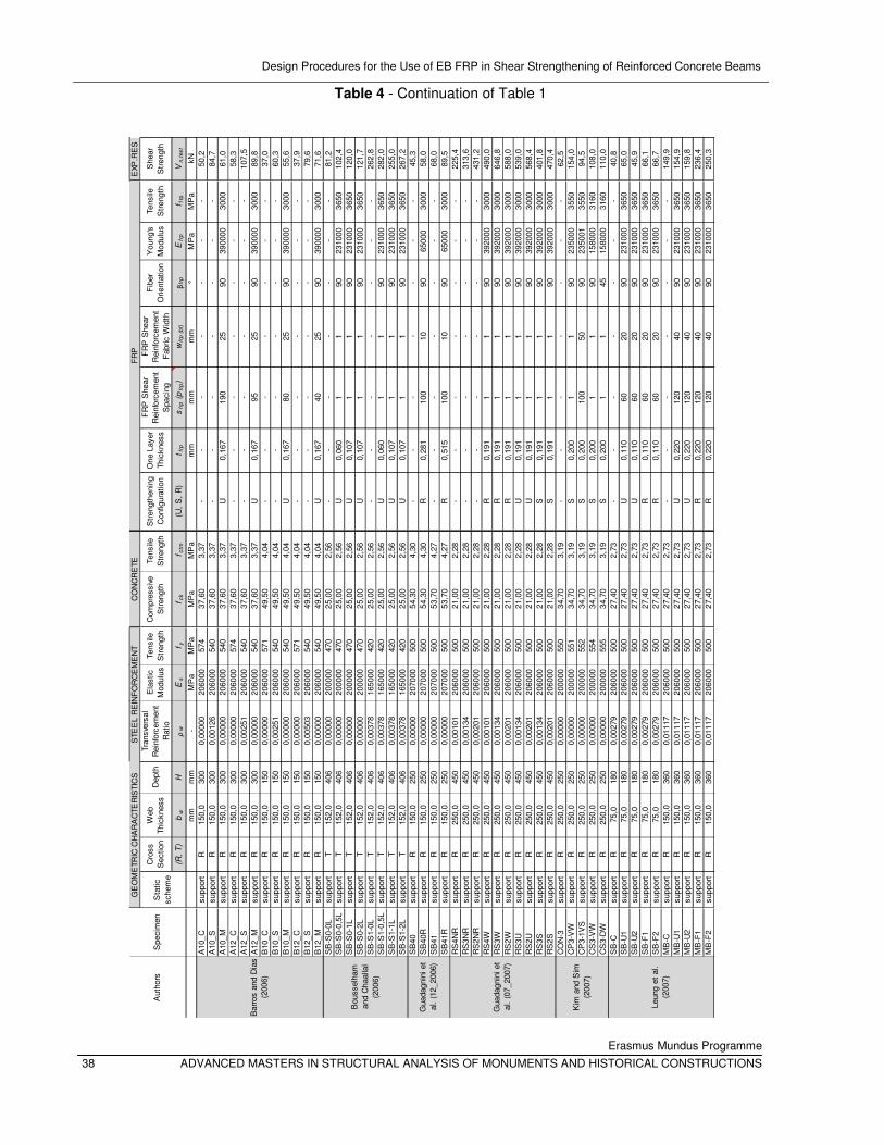
Design Procedures for the Use of EB FRP in Shear Strengthening of Reinforced Concrete Beams
Erasmus Mundus Programme
38 ADVANCED MASTERS IN STRUCTURAL ANALYSIS OF MONUMENTS AND HISTORICAL CONSTRUCTIONS
Cro
ss
Sec
tion
Web
Th
ickn
ess
Dep
thTr
ansv
ersa
l R
einf
orce
men
t R
atio
Ela
stic
M
odul
usTe
nsile
S
tren
gth
Com
pres
sive
S
tren
gth
Tens
ile
Str
engt
hS
tren
gthe
ning
C
onfig
urat
ion
One
Lay
er
Thic
knes
s
FR
P S
hear
R
einf
orce
men
t S
paci
ng
FR
P S
hear
R
einf
orce
men
t F
abric
Wid
th
Fib
er
Orie
ntat
ion
You
ng's
M
odul
usTe
nsile
S
tren
gth
She
ar
Str
engt
h
(R,
T)
bw
Hρ
wE
sf y
f ck
f ctm
(U,
S,
R)
t frp
sfr
p (
pfr
p)
wfr
p (
bf)
βfr
pE
frp
f frp
Vn
,te
st
mm
mm
-M
Pa
MP
aM
Pa
MP
am
mm
mm
m°
MP
aM
Pa
kNA
10_C
supp
ort
R15
0,0
300
0,00
000
2060
0057
437
,60
3,37
--
--
--
-50
,2A
10_S
supp
ort
R15
0,0
300
0,00
126
2060
0054
037
,60
3,37
--
--
--
-84
,7A
10_M
supp
ort
R15
0,0
300
0,00
000
2060
0054
037
,60
3,37
U0,
167
190
2590
3900
0030
0061
,0A
12_C
supp
ort
R15
0,0
300
0,00
000
2060
0057
437
,60
3,37
--
--
--
-58
,3A
12_S
supp
ort
R15
0,0
300
0,00
251
2060
0054
037
,60
3,37
--
--
--
-10
7,5
A12
_Msu
ppor
tR
150,
030
00,
0000
020
6000
540
37,6
03,
37U
0,16
795
2590
3900
0030
0089
,8B
10_C
supp
ort
R15
0,0
150
0,00
000
2060
0057
149
,50
4,04
--
--
--
-37
,0B
10_S
supp
ort
R15
0,0
150
0,00
251
2060
0054
049
,50
4,04
--
--
--
-60
,3B
10_M
supp
ort
R15
0,0
150
0,00
000
2060
0054
049
,50
4,04
U0,
167
8025
9039
0000
3000
55,6
B12
_Csu
ppor
tR
150,
015
00,
0000
020
6000
571
49,5
04,
04-
--
--
--
37,9
B12
_Ssu
ppor
tR
150,
015
00,
0050
320
6000
540
49,5
04,
04-
--
--
--
79,6
B12
_Msu
ppor
tR
150,
015
00,
0000
020
6000
540
49,5
04,
04U
0,16
740
2590
3900
0030
0071
,6S
B-S
0-0L
supp
ort
T15
2,0
406
0,00
000
2000
0047
025
,00
2,56
--
--
--
-81
,2S
B-S
0-0,
5Lsu
ppor
tT
152,
040
60,
0000
020
0000
470
25,0
02,
56U
0,06
01
190
2310
0036
5010
2,4
SB
-S0-
1Lsu
ppor
tT
152,
040
60,
0000
020
0000
470
25,0
02,
56U
0,10
71
190
2310
0036
5012
0,0
SB
-S0-
2Lsu
ppor
tT
152,
040
60,
0000
020
0000
470
25,0
02,
56U
0,10
71
190
2310
0036
5012
1,7
SB
-S1-
0Lsu
ppor
tT
152,
040
60,
0037
816
5000
420
25,0
02,
56-
--
--
--
262,
8S
B-S
1-0,
5Lsu
ppor
tT
152,
040
60,
0037
816
5000
420
25,0
02,
56U
0,06
01
190
2310
0036
5028
2,0
SB
-S1-
1Lsu
ppor
tT
152,
040
60,
0037
816
5000
420
25,0
02,
56U
0,10
71
190
2310
0036
5025
5,0
SB
-S1-
2Lsu
ppor
tT
152,
040
60,
0037
816
5000
420
25,0
02,
56U
0,10
71
190
2310
0036
5026
7,2
SB
40su
ppor
tR
150,
025
00,
0000
020
7000
500
54,3
04,
30-
--
--
--
45,3
SB
40R
supp
ort
R15
0,0
250
0,00
000
2070
0050
054
,30
4,30
R0,
281
100
1090
6500
030
0058
,0S
B41
supp
ort
R15
0,0
250
0,00
000
2070
0050
053
,70
4,27
--
--
--
-68
,0S
B41
Rsu
ppor
tR
150,
025
00,
0000
020
7000
500
53,7
04,
27R
0,51
510
010
9065
000
3000
89,5
RS
4NR
supp
ort
R25
0,0
450
0,00
101
2060
0050
021
,00
2,28
--
--
--
-22
5,4
RS
3NR
supp
ort
R25
0,0
450
0,00
134
2060
0050
021
,00
2,28
--
--
--
-31
3,6
RS
2NR
supp
ort
R25
0,0
450
0,00
201
2060
0050
021
,00
2,28
--
--
--
-43
1,2
RS
4Wsu
ppor
tR
250,
045
00,
0010
120
6000
500
21,0
02,
28R
0,19
11
190
3920
0030
0049
0,0
RS
3Wsu
ppor
tR
250,
045
00,
0013
420
6000
500
21,0
02,
28R
0,19
11
190
3920
0030
0064
6,8
RS
2Wsu
ppor
tR
250,
045
00,
0020
120
6000
500
21,0
02,
28R
0,19
11
190
3920
0030
0058
8,0
RS
3Usu
ppor
tR
250,
045
00,
0013
420
6000
500
21,0
02,
28U
0,19
11
190
3920
0030
0053
9,0
RS
2Usu
ppor
tR
250,
045
00,
0020
120
6000
500
21,0
02,
28U
0,19
11
190
3920
0030
0056
8,4
RS
3Ssu
ppor
tR
250,
045
00,
0013
420
6000
500
21,0
02,
28S
0,19
11
190
3920
0030
0040
1,8
RS
2Ssu
ppor
tR
250,
045
00,
0020
120
6000
500
21,0
02,
28S
0,19
11
190
3920
0030
0047
0,4
CO
N-3
supp
ort
R25
0,0
250
0,00
000
2000
0055
034
,70
3,19
--
--
--
-62
,5C
P3-
VW
supp
ort
R25
0,0
250
0,00
000
2000
0055
134
,70
3,19
S0,
200
11
9023
5000
3550
154,
0C
P3-
1VS
supp
ort
R25
0,0
250
0,00
000
2000
0055
234
,70
3,19
S0,
200
100
5090
2350
0135
5094
,5C
S3-
VW
supp
ort
R25
0,0
250
0,00
000
2000
0055
434
,70
3,19
S0,
200
11
9015
8000
3160
108,
0C
S3-
DW
supp
ort
R25
0,0
250
0,00
000
2000
0055
534
,70
3,19
S0,
200
11
4515
8000
3160
110,
0S
B-C
supp
ort
R75
,018
00,
0027
920
6000
500
27,4
02,
73-
--
--
--
40,8
SB
-U1
supp
ort
R75
,018
00,
0027
920
6000
500
27,4
02,
73U
0,11
060
2090
2310
0036
5065
,0S
B-U
2su
ppor
tR
75,0
180
0,00
279
2060
0050
027
,40
2,73
U0,
110
6020
9023
1000
3650
45,9
SB
-F1
supp
ort
R75
,018
00,
0027
920
6000
500
27,4
02,
73R
0,11
060
2090
2310
0036
5066
,1S
B-F
2su
ppor
tR
75,0
180
0,00
279
2060
0050
027
,40
2,73
R0,
110
6020
9023
1000
3650
66,7
MB
-Csu
ppor
tR
150,
036
00,
0111
720
6000
500
27,4
02,
73-
--
--
--
149,
9M
B-U
1su
ppor
tR
150,
036
00,
0111
720
6000
500
27,4
02,
73U
0,22
012
040
9023
1000
3650
154,
9M
B-U
2su
ppor
tR
150,
036
00,
0111
720
6000
500
27,4
02,
73U
0,22
012
040
9023
1000
3650
159,
8M
B-F
1su
ppor
tR
150,
036
00,
0111
720
6000
500
27,4
02,
73R
0,22
012
040
9023
1000
3650
236,
4M
B-F
2su
ppor
tR
150,
036
00,
0111
720
6000
500
27,4
02,
73R
0,22
012
040
9023
1000
3650
250,
3
Spe
cim
en
GE
OM
ETR
IC C
HA
RA
CTE
RIS
TIC
SS
TEE
L R
EIN
FO
RC
EM
EN
TC
ON
CR
ETE
FR
PE
XP.R
ES
Sta
tic
sche
me
Gua
dagn
ini e
t al
. (1
2_20
06)
Aut
hors
Kim
and
Sim
(2
007)
Bar
ros
and
Dia
s (2
006)
Bou
ssel
ham
an
d C
haal
lal
(200
6)
Gua
dagn
ini e
t al
. (0
7_20
07)
Leun
g et
al.
(200
7)
Table 4 - Continuation of Table 1
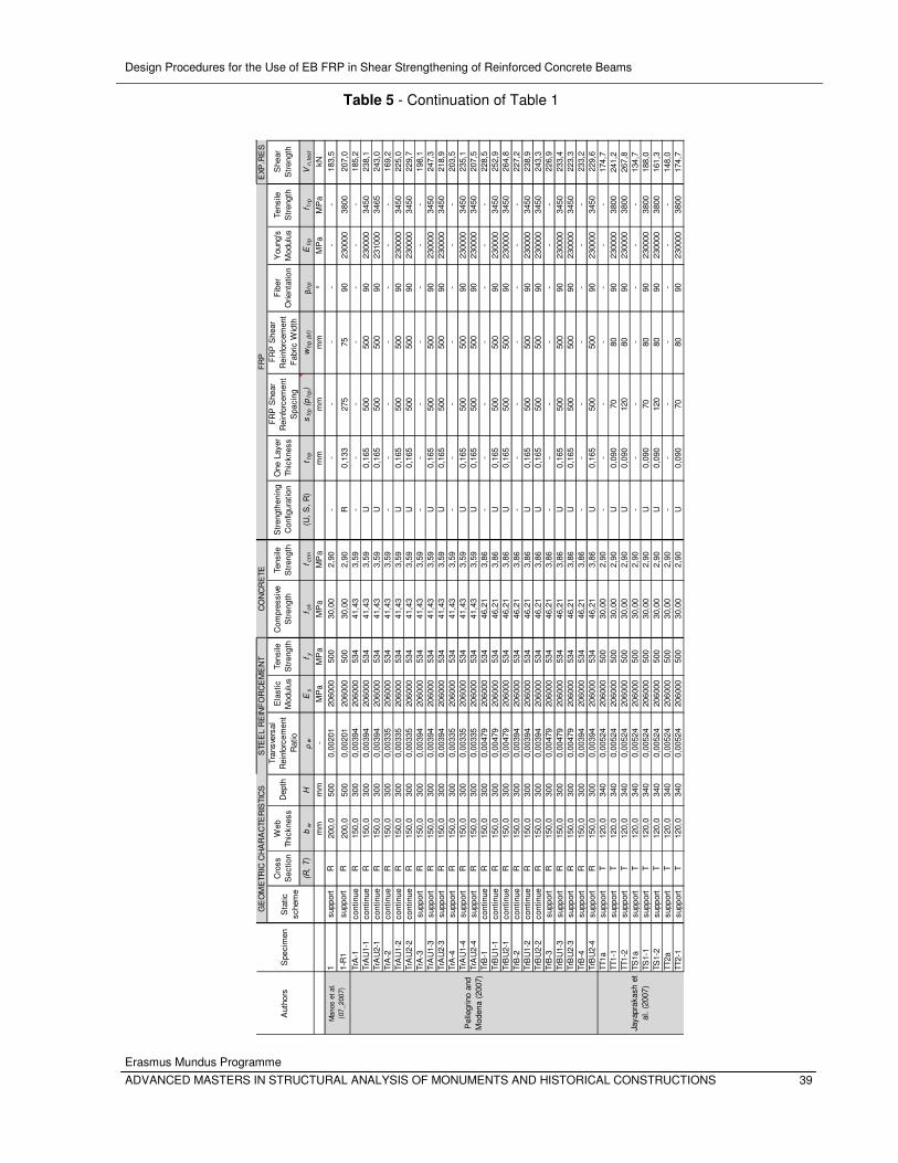
Design Procedures for the Use of EB FRP in Shear Strengthening of Reinforced Concrete Beams
Erasmus Mundus Programme
ADVANCED MASTERS IN STRUCTURAL ANALYSIS OF MONUMENTS AND HISTORICAL CONSTRUCTIONS 39
Cro
ss
Sec
tion
Web
Th
ickn
ess
Dep
thTr
ansv
ersa
l R
einf
orce
men
t R
atio
Ela
stic
M
odul
usTe
nsile
S
tren
gth
Com
pres
sive
S
tren
gth
Tens
ile
Str
engt
hS
tren
gthe
ning
C
onfig
urat
ion
One
Lay
er
Thic
knes
s
FR
P S
hear
R
einf
orce
men
t S
paci
ng
FR
P S
hear
R
einf
orce
men
t F
abric
Wid
th
Fib
er
Orie
ntat
ion
You
ng's
M
odul
usTe
nsile
S
tren
gth
She
ar
Str
engt
h
(R,
T)
bw
Hρ
wE
sf y
f ck
f ctm
(U,
S,
R)
t frp
sfr
p (
pfr
p)
wfr
p (
bf)
βfr
pE
frp
f frp
Vn
,te
st
mm
mm
-M
Pa
MP
aM
Pa
MP
am
mm
mm
m°
MP
aM
Pa
kN1
supp
ort
R20
0,0
500
0,00
201
2060
0050
030
,00
2,90
--
--
--
-18
3,5
1-R
1su
ppor
tR
200,
050
00,
0020
120
6000
500
30,0
02,
90R
0,13
327
575
9023
0000
3800
207,
0Tr
A-1
cont
inue
R15
0,0
300
0,00
394
2060
0053
441
,43
3,59
--
--
--
-18
5,2
TrA
U1-
1co
ntin
ueR
150,
030
00,
0039
420
6000
534
41,4
33,
59U
0,16
550
050
090
2300
0034
5023
8,1
TrA
U2-
1co
ntin
ueR
150,
030
00,
0039
420
6000
534
41,4
33,
59U
0,16
550
050
090
2310
0034
6524
3,0
TrA
-2co
ntin
ueR
150,
030
00,
0033
520
6000
534
41,4
33,
59-
--
--
--
169,
2Tr
AU
1-2
cont
inue
R15
0,0
300
0,00
335
2060
0053
441
,43
3,59
U0,
165
500
500
9023
0000
3450
225,
0Tr
AU
2-2
cont
inue
R15
0,0
300
0,00
335
2060
0053
441
,43
3,59
U0,
165
500
500
9023
0000
3450
229,
7Tr
A-3
supp
ort
R15
0,0
300
0,00
394
2060
0053
441
,43
3,59
--
--
--
-19
8,1
TrA
U1-
3su
ppor
tR
150,
030
00,
0039
420
6000
534
41,4
33,
59U
0,16
550
050
090
2300
0034
5024
7,3
TrA
U2-
3su
ppor
tR
150,
030
00,
0039
420
6000
534
41,4
33,
59U
0,16
550
050
090
2300
0034
5021
8,9
TrA
-4su
ppor
tR
150,
030
00,
0033
520
6000
534
41,4
33,
59-
--
--
--
203,
5Tr
AU
1-4
supp
ort
R15
0,0
300
0,00
335
2060
0053
441
,43
3,59
U0,
165
500
500
9023
0000
3450
235,
1Tr
AU
2-4
supp
ort
R15
0,0
300
0,00
335
2060
0053
441
,43
3,59
U0,
165
500
500
9023
0000
3450
207,
5Tr
B-1
cont
inue
R15
0,0
300
0,00
479
2060
0053
446
,21
3,86
--
--
--
-22
8,5
TrB
U1-
1co
ntin
ueR
150,
030
00,
0047
920
6000
534
46,2
13,
86U
0,16
550
050
090
2300
0034
5025
2,9
TrB
U2-
1co
ntin
ueR
150,
030
00,
0047
920
6000
534
46,2
13,
86U
0,16
550
050
090
2300
0034
5026
4,8
TrB
-2co
ntin
ueR
150,
030
00,
0039
420
6000
534
46,2
13,
86-
--
--
--
227,
2Tr
BU
1-2
cont
inue
R15
0,0
300
0,00
394
2060
0053
446
,21
3,86
U0,
165
500
500
9023
0000
3450
238,
9Tr
BU
2-2
cont
inue
R15
0,0
300
0,00
394
2060
0053
446
,21
3,86
U0,
165
500
500
9023
0000
3450
243,
3Tr
B-3
supp
ort
R15
0,0
300
0,00
479
2060
0053
446
,21
3,86
--
--
--
-22
6,9
TrB
U1-
3su
ppor
tR
150,
030
00,
0047
920
6000
534
46,2
13,
86U
0,16
550
050
090
2300
0034
5023
3,4
TrB
U2-
3su
ppor
tR
150,
030
00,
0047
920
6000
534
46,2
13,
86U
0,16
550
050
090
2300
0034
5022
3,3
TrB
-4su
ppor
tR
150,
030
00,
0039
420
6000
534
46,2
13,
86-
--
--
--
233,
2Tr
BU
2-4
supp
ort
R15
0,0
300
0,00
394
2060
0053
446
,21
3,86
U0,
165
500
500
9023
0000
3450
229,
6TT
1asu
ppor
tT
120,
034
00,
0052
420
6000
500
30,0
02,
90-
--
--
--
174,
7TT
1-1
supp
ort
T12
0,0
340
0,00
524
2060
0050
030
,00
2,90
U0,
090
7080
9023
0000
3800
241,
2TT
1-2
supp
ort
T12
0,0
340
0,00
524
2060
0050
030
,00
2,90
U0,
090
120
8090
2300
0038
0026
7,8
TS1a
supp
ort
T12
0,0
340
0,00
524
2060
0050
030
,00
2,90
--
--
--
-13
4,7
TS1-
1su
ppor
tT
120,
034
00,
0052
420
6000
500
30,0
02,
90U
0,09
070
8090
2300
0038
0018
8,0
TS1-
2su
ppor
tT
120,
034
00,
0052
420
6000
500
30,0
02,
90U
0,09
012
080
9023
0000
3800
161,
3TT
2asu
ppor
tT
120,
034
00,
0052
420
6000
500
30,0
02,
90-
--
--
--
148,
0TT
2-1
supp
ort
T12
0,0
340
0,00
524
2060
0050
030
,00
2,90
U0,
090
7080
9023
0000
3800
174,
7
Spe
cim
en
GE
OM
ETR
IC C
HA
RA
CTE
RIS
TIC
SS
TEE
L R
EIN
FO
RC
EM
EN
TC
ON
CR
ETE
FR
PE
XP.R
ES
Sta
tic
sche
me
Pel
legr
ino
and
Mod
ena
(200
7)
Aut
hors
Jaya
prak
ash
et
al.
(200
7)
Man
os e
t al.
(07_
2007
)
Table 5 - Continuation of Table 1
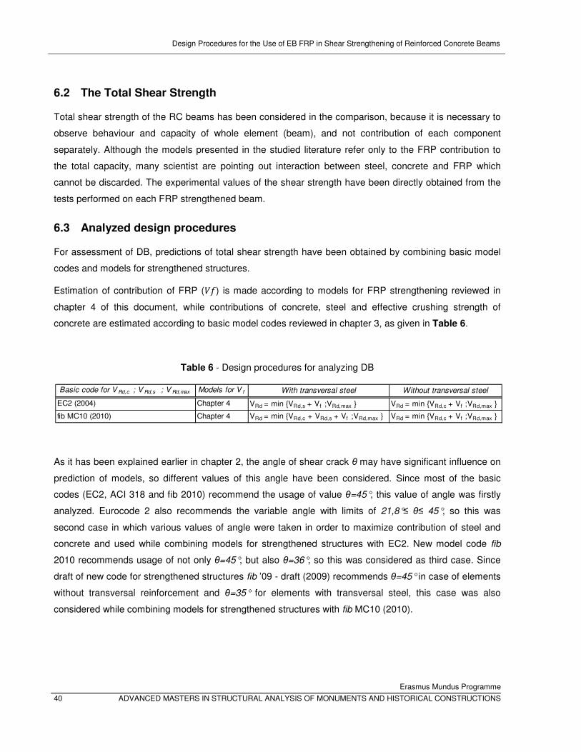
Design Procedures for the Use of EB FRP in Shear Strengthening of Reinforced Concrete Beams
Erasmus Mundus Programme
40 ADVANCED MASTERS IN STRUCTURAL ANALYSIS OF MONUMENTS AND HISTORICAL CONSTRUCTIONS
6.2 The Total Shear Strength
Total shear strength of the RC beams has been considered in the comparison, because it is necessary to
observe behaviour and capacity of whole element (beam), and not contribution of each component
separately. Although the models presented in the studied literature refer only to the FRP contribution to
the total capacity, many scientist are pointing out interaction between steel, concrete and FRP which
cannot be discarded. The experimental values of the shear strength have been directly obtained from the
tests performed on each FRP strengthened beam.
6.3 Analyzed design procedures
For assessment of DB, predictions of total shear strength have been obtained by combining basic model
codes and models for strengthened structures.
Estimation of contribution of FRP (�*) is made according to models for FRP strengthening reviewed in
chapter 4 of this document, while contributions of concrete, steel and effective crushing strength of
concrete are estimated according to basic model codes reviewed in chapter 3, as given in Table 6.
Table 6 - Design procedures for analyzing DB
As it has been explained earlier in chapter 2, the angle of shear crack θ may have significant influence on
prediction of models, so different values of this angle have been considered. Since most of the basic
codes (EC2, ACI 318 and fib 2010) recommend the usage of value θ=45°, this value of angle was firstly
analyzed. Eurocode 2 also recommends the variable angle with limits of 21,8°≤ θ≤ 45°, so this was
second case in which various values of angle were taken in order to maximize contribution of steel and
concrete and used while combining models for strengthened structures with EC2. New model code fib
2010 recommends usage of not only θ=45°, but also θ=36°, so this was considered as third case. Since
draft of new code for strengthened structures fib ’09 - draft (2009) recommends θ=45° in case of elements
without transversal reinforcement and θ=35° for elements with transversal steel, this case was also
considered while combining models for strengthened structures with fib MC10 (2010).
Basic code for V Rd,c ; V Rd,s ; V Rd,max Models for V f With transversal steel Without transversal steel
EC2 (2004) Chapter 4 VRd = min {VRd,s + Vf ;VRd,max } VRd = min {VRd,c + Vf ;VRd,max }
fib MC10 (2010) Chapter 4 VRd = min {VRd,c + VRd,s + Vf ;VRd,max } VRd = min {VRd,c + Vf ;VRd,max }
Design Procedures for the Use of EB FRP in Shear Strengthening of Reinforced Concrete Beams
Erasmus Mundus Programme
ADVANCED MASTERS IN STRUCTURAL ANALYSIS OF MONUMENTS AND HISTORICAL CONSTRUCTIONS 41
6.4 General statistical analysis procedures
The performance of FIB, ACI, CNR design models and recent model proposals was appraised using the
collected data registered in the DB. For each design model, the obtained values of ��,�§�¨ were compared
with ��,��� , and a factor ©, corresponding to ��,���/��,�§�¨, was evaluated. On the performed analysis, ��,�§�¨ is the design value of the global shear resistance predicted by the design model and ��,��� is the
shear resistance obtained based on experimental results. In each plot of results, a line © = 1.0 establishes
the division between safe (conservative) and unconservative predictions.
The main descriptive statistical measures analyzed in this study are percentage of conservative
predictions, the average (AVG), the standard deviation (std) and the coefficient of variation (CoV). In
further study, CoV and AVG will be taken as main parameters, since they are both indicators of accuracy.
The average (AVG) represents a global safety factor associated with the design procedure. A coefficient
of variation (CoV) is calculated and interpreted analyzing a single variable. The formulation of the CoV is
the ratio of the standard deviation to the mean value, and it aims to describe the dispersion of the variable
in a way that does not depend on the variable's measurement unit. For higher values of CoV, the
dispersion in the variable is greater. The advantage of the CoV is that it is unitless. This allows CoV to be
compared to each other in ways that other measures, like standard deviations or root mean squared
residuals, cannot be.

Design Procedures for the Use of EB FRP in Shear Strengthening of Reinforced Concrete Beams
Erasmus Mundus Programme
42 ADVANCED MASTERS IN STRUCTURAL ANALYSIS OF MONUMENTS AND HISTORICAL CONSTRUCTIONS
Design Procedures for the Use of EB FRP in Shear Strengthening of Reinforced Concrete Beams
Erasmus Mundus Programme
ADVANCED MASTERS IN STRUCTURAL ANALYSIS OF MONUMENTS AND HISTORICAL CONSTRUCTIONS 43
7. RESULTS AND DISCUSSION
It should be pointed out once more that in this study, the total shear strength of element is considered.
This is done by taking into account the fact that the influence of the steel and shear contributions
estimated by the respective codes does not allow having a clear understanding of the predictions given for
the individual FRP contribution. In addition, as it was stated before, the scope of this document is to study
the equations for FRP systems due to their more recent development and need of validation.
*notification: since guideline fib ‘09 (2009) does not recognize difference between U-jacketed and side
bonded configurations, all data of side bonded configurations were in case of fib treated as U-jacketed
and shown in previous figures.
7.1 Assessment of Pellegrino and Modena (2008) model and its improvement
Analyzing recently proposed models for strengthening of RC structures (explained in details in chapter 5
of this study), author found model of Pellegrino and Modena specially interesting cause it distinguishes
from other models by taking into account interaction between the internal steel and external FRP and
considering variable angle θ. Results predicted by this model are very good comparing to other models
and codes. In order to improve this model, author of this study analyzed different parameters that are
configuring in equations proposed by Pellegrino and Modena (2008). As a result, a different value of the
angle characterizing the conventional roughness of the interface is proposed in this study.
Originally, Pellegrino and Modena have proposed their model (Pellegrino and Modena, An Experimentaly
Based Analytical Model for the Shear Capacity of FRP-strenghtened Reinforced Concrete Beams 2008) in
which this angle was assumed to be equal to w=79°, according to the calibration process based on the
experimental ultimate shear capacities obtained in their experimental investigation. After considering
several values of this angle, author of this study has found an optimal value w=75°, which gives
improvement of Pellegrino and Modena model in 21 out of 24 cases considering different basic model
code and angle of shear crack, θ. The main descriptive statistical measures are summarized in Table 7,
regarding percentage of conservative predictions, the average (AVG), the standard deviation (std) and the
coefficient of variation (CoV). It can be noticed that modification of this angle from w=79° to w=75°,
improves model not only in sense of CoV, but also in sense of AVG.
Model of Pellegrino and Modena will be analyzed in further study as two cases: firstly with original value w=79° for angle characterizing the conventional roughness of the interface and secondly, as modified
model, with w=79°.
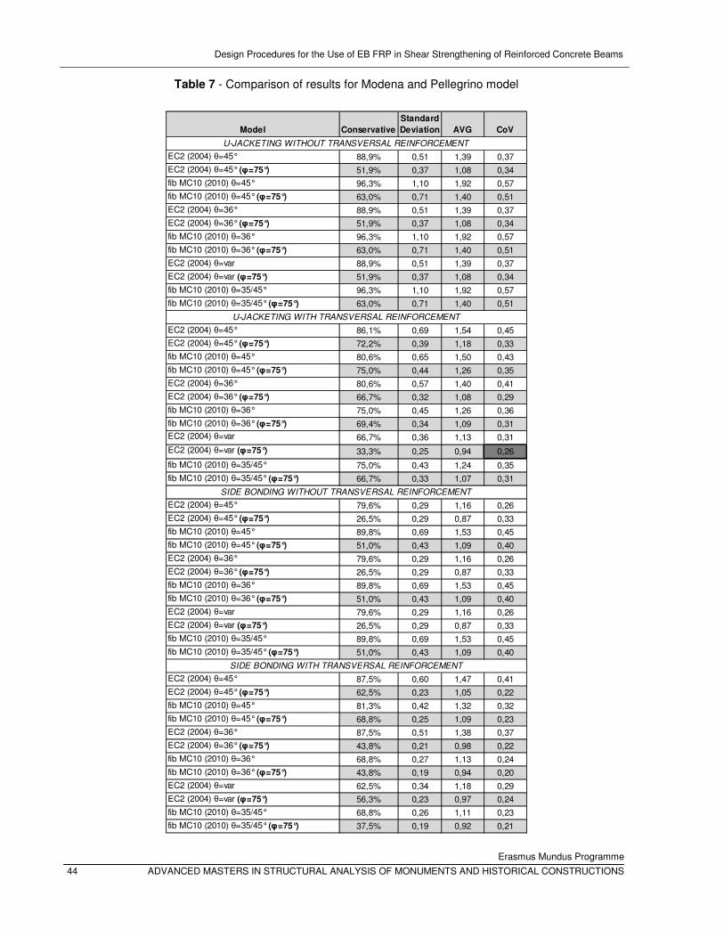
Design Procedures for the Use of EB FRP in Shear Strengthening of Reinforced Concrete Beams
Erasmus Mundus Programme
44 ADVANCED MASTERS IN STRUCTURAL ANALYSIS OF MONUMENTS AND HISTORICAL CONSTRUCTIONS
Table 7 - Comparison of results for Modena and Pellegrino model
Model Conservative
Standard
Deviation AVG CoV
EC2 (2004) θ=45° 88,9% 0,51 1,39 0,37
EC2 (2004) θ=45° (φ=75°) 51,9% 0,37 1,08 0,34
fib MC10 (2010) θ=45° 96,3% 1,10 1,92 0,57
fib MC10 (2010) θ=45° (φ=75°) 63,0% 0,71 1,40 0,51
EC2 (2004) θ=36° 88,9% 0,51 1,39 0,37
EC2 (2004) θ=36° (φ=75°) 51,9% 0,37 1,08 0,34
fib MC10 (2010) θ=36° 96,3% 1,10 1,92 0,57
fib MC10 (2010) θ=36° (φ=75°) 63,0% 0,71 1,40 0,51
EC2 (2004) θ=var 88,9% 0,51 1,39 0,37
EC2 (2004) θ=var (φ=75°) 51,9% 0,37 1,08 0,34
fib MC10 (2010) θ=35/45° 96,3% 1,10 1,92 0,57
fib MC10 (2010) θ=35/45° (φ=75°) 63,0% 0,71 1,40 0,51
EC2 (2004) θ=45° 86,1% 0,69 1,54 0,45
EC2 (2004) θ=45° (φ=75°) 72,2% 0,39 1,18 0,33
fib MC10 (2010) θ=45° 80,6% 0,65 1,50 0,43
fib MC10 (2010) θ=45° (φ=75°) 75,0% 0,44 1,26 0,35
EC2 (2004) θ=36° 80,6% 0,57 1,40 0,41
EC2 (2004) θ=36° (φ=75°) 66,7% 0,32 1,08 0,29
fib MC10 (2010) θ=36° 75,0% 0,45 1,26 0,36
fib MC10 (2010) θ=36° (φ=75°) 69,4% 0,34 1,09 0,31EC2 (2004) θ=var 66,7% 0,36 1,13 0,31
EC2 (2004) θ=var (φ=75°) 33,3% 0,25 0,94 0,26
fib MC10 (2010) θ=35/45° 75,0% 0,43 1,24 0,35
fib MC10 (2010) θ=35/45° (φ=75°) 66,7% 0,33 1,07 0,31
EC2 (2004) θ=45° 79,6% 0,29 1,16 0,26
EC2 (2004) θ=45° (φ=75°) 26,5% 0,29 0,87 0,33
fib MC10 (2010) θ=45° 89,8% 0,69 1,53 0,45
fib MC10 (2010) θ=45° (φ=75°) 51,0% 0,43 1,09 0,40
EC2 (2004) θ=36° 79,6% 0,29 1,16 0,26
EC2 (2004) θ=36° (φ=75°) 26,5% 0,29 0,87 0,33
fib MC10 (2010) θ=36° 89,8% 0,69 1,53 0,45
fib MC10 (2010) θ=36° (φ=75°) 51,0% 0,43 1,09 0,40
EC2 (2004) θ=var 79,6% 0,29 1,16 0,26
EC2 (2004) θ=var (φ=75°) 26,5% 0,29 0,87 0,33
fib MC10 (2010) θ=35/45° 89,8% 0,69 1,53 0,45
fib MC10 (2010) θ=35/45° (φ=75°) 51,0% 0,43 1,09 0,40
EC2 (2004) θ=45° 87,5% 0,60 1,47 0,41
EC2 (2004) θ=45° (φ=75°) 62,5% 0,23 1,05 0,22
fib MC10 (2010) θ=45° 81,3% 0,42 1,32 0,32
fib MC10 (2010) θ=45° (φ=75°) 68,8% 0,25 1,09 0,23
EC2 (2004) θ=36° 87,5% 0,51 1,38 0,37
EC2 (2004) θ=36° (φ=75°) 43,8% 0,21 0,98 0,22
fib MC10 (2010) θ=36° 68,8% 0,27 1,13 0,24
fib MC10 (2010) θ=36° (φ=75°) 43,8% 0,19 0,94 0,20
EC2 (2004) θ=var 62,5% 0,34 1,18 0,29
EC2 (2004) θ=var (φ=75°) 56,3% 0,23 0,97 0,24
fib MC10 (2010) θ=35/45° 68,8% 0,26 1,11 0,23
fib MC10 (2010) θ=35/45° (φ=75°) 37,5% 0,19 0,92 0,21
U-JACKETING WITHOUT TRANSVERSAL REINFORCEMENT
U-JACKETING WITH TRANSVERSAL REINFORCEMENT
SIDE BONDING WITHOUT TRANSVERSAL REINFORCEMENT
SIDE BONDING WITH TRANSVERSAL REINFORCEMENT
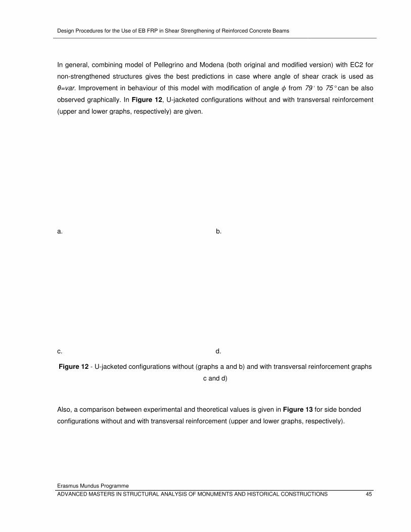
Design Procedures for the Use of EB FRP in Shear Strengthening of Reinforced Concrete Beams
Erasmus Mundus Programme
ADVANCED MASTERS IN STRUCTURAL ANALYSIS OF MONUMENTS AND HISTORICAL CONSTRUCTIONS
In general, combining model of Pellegrino and Modena (both original and modified version) with EC2 for
non-strengthened structures gives the best predictions in case where angle of shear crack is used as
θ=var. Improvement in behaviour of this model with m
observed graphically. In Figure
(upper and lower graphs, respectively) are given.
a.
c.
Figure 12 - U-jacketed configurations without
Also, a comparison between experimental and theoretical
configurations without and with transversal reinforcement (upper and lower graphs, respectively).
Design Procedures for the Use of EB FRP in Shear Strengthening of Reinforced Concrete Beams
MASTERS IN STRUCTURAL ANALYSIS OF MONUMENTS AND HISTORICAL CONSTRUCTIONS
In general, combining model of Pellegrino and Modena (both original and modified version) with EC2 for
strengthened structures gives the best predictions in case where angle of shear crack is used as
Improvement in behaviour of this model with modification of angle w from 79°
Figure 12, U-jacketed configurations without and with transversal reinforcement
d lower graphs, respectively) are given.
b.
d.
jacketed configurations without (graphs a and b) and with transversal reinforcement
c and d)
Also, a comparison between experimental and theoretical values is given in Figure 13
configurations without and with transversal reinforcement (upper and lower graphs, respectively).
MASTERS IN STRUCTURAL ANALYSIS OF MONUMENTS AND HISTORICAL CONSTRUCTIONS 45
In general, combining model of Pellegrino and Modena (both original and modified version) with EC2 for
strengthened structures gives the best predictions in case where angle of shear crack is used as
79° to 75° can be also
jacketed configurations without and with transversal reinforcement
and with transversal reinforcement graphs
13 for side bonded
configurations without and with transversal reinforcement (upper and lower graphs, respectively).
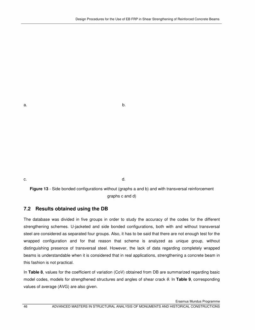
Design Procedures for the Use of EB FRP in Shear Strengthening of Reinforced Concrete Beams
46 ADVANCED MASTERS IN STRUCTURAL ANALYSIS OF MONUMENTS AND HISTORICAL CONSTRUCTIONS
a.
c.
Figure 13 - Side bonded configurations
7.2 Results obtained using the
The database was divided in five groups in order to study the accuracy of the codes for the different
strengthening schemes. U-jacketed and side bonded configurations, both with and without transversal
steel are considered as separated four groups. Also, i
wrapped configuration and for that reason that scheme is analyzed as unique group, without
distinguishing presence of transversal steel. However, the lack of data regarding completely wrapped
beams is understandable when it is considered that in real applications, strengthening a concrete beam in
this fashion is not practical.
In Table 8, values for the coefficient of variation (CoV) obtained from DB
model codes, models for strengthened structures and angles of shear crack
values of average (AVG) are also given.
Design Procedures for the Use of EB FRP in Shear Strengthening of Reinforced Concrete Beams
Erasmus Mundus Programme
ADVANCED MASTERS IN STRUCTURAL ANALYSIS OF MONUMENTS AND HISTORICAL CONSTRUCTIONS
b.
d.
configurations without (graphs a and b) and with transversal reinforcement
graphs c and d)
Results obtained using the DB
The database was divided in five groups in order to study the accuracy of the codes for the different
jacketed and side bonded configurations, both with and without transversal
steel are considered as separated four groups. Also, it has to be said that there are not enough test for the
wrapped configuration and for that reason that scheme is analyzed as unique group, without
distinguishing presence of transversal steel. However, the lack of data regarding completely wrapped
understandable when it is considered that in real applications, strengthening a concrete beam in
of variation (CoV) obtained from DB are summarized regarding
model codes, models for strengthened structures and angles of shear crack θ. In Table 9
values of average (AVG) are also given.
Design Procedures for the Use of EB FRP in Shear Strengthening of Reinforced Concrete Beams
Erasmus Mundus Programme
ADVANCED MASTERS IN STRUCTURAL ANALYSIS OF MONUMENTS AND HISTORICAL CONSTRUCTIONS
without (graphs a and b) and with transversal reinforcement
The database was divided in five groups in order to study the accuracy of the codes for the different
jacketed and side bonded configurations, both with and without transversal
t has to be said that there are not enough test for the
wrapped configuration and for that reason that scheme is analyzed as unique group, without
distinguishing presence of transversal steel. However, the lack of data regarding completely wrapped
understandable when it is considered that in real applications, strengthening a concrete beam in
are summarized regarding basic
, corresponding
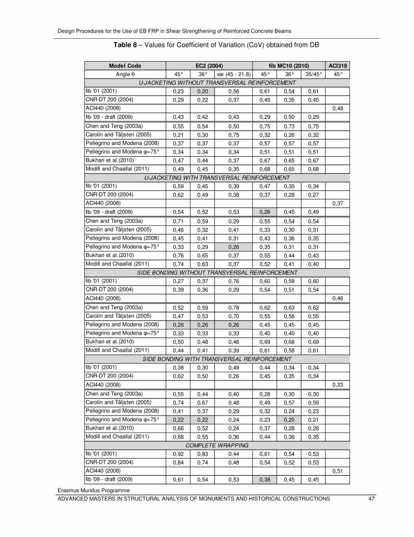
Design Procedures for the Use of EB FRP in Shear Strengthening of Reinforced Concrete Beams
Erasmus Mundus Programme
ADVANCED MASTERS IN STRUCTURAL ANALYSIS OF MONUMENTS AND HISTORICAL CONSTRUCTIONS 47
Table 8 – Values for Coefficient of Variation (CoV) obtained from DB
Model Code ACI318
Angle θ 45° 36° var (45 - 21.8) 45° 36° 35/45° 45°
fib '01 (2001) 0,23 0,20 0,56 0,61 0,54 0,61
CNR-DT 200 (2004) 0,29 0,22 0,37 0,45 0,35 0,45
ACI440 (2008) 0,48
fib '09 - draft (2009) 0,43 0,42 0,43 0,29 0,50 0,29
Chen and Teng (2003a) 0,55 0,54 0,50 0,75 0,73 0,75
Carolin and Täljsten (2005) 0,21 0,30 0,75 0,32 0,26 0,32
Pellegrino and Modena (2008) 0,37 0,37 0,37 0,57 0,57 0,57
Pellegrino and Modena φ=75° 0,34 0,34 0,34 0,51 0,51 0,51
Bukhari et al.(2010) 0,47 0,44 0,37 0,67 0,65 0,67
Modifi and Chaallal (2011) 0,49 0,45 0,35 0,68 0,65 0,68
fib '01 (2001) 0,59 0,45 0,39 0,47 0,35 0,34
CNR-DT 200 (2004) 0,62 0,49 0,38 0,37 0,28 0,27
ACI440 (2008) 0,37
fib '09 - draft (2009) 0,54 0,52 0,53 0,26 0,45 0,49
Chen and Teng (2003a) 0,71 0,59 0,29 0,55 0,54 0,54
Carolin and Täljsten (2005) 0,46 0,32 0,41 0,33 0,30 0,31
Pellegrino and Modena (2008) 0,45 0,41 0,31 0,43 0,36 0,35
Pellegrino and Modena φ=75° 0,33 0,29 0,26 0,35 0,31 0,31
Bukhari et al.(2010) 0,76 0,65 0,37 0,55 0,44 0,43
Modifi and Chaallal (2011) 0,74 0,63 0,37 0,52 0,41 0,40
fib '01 (2001) 0,27 0,37 0,76 0,60 0,58 0,60
CNR-DT 200 (2004) 0,39 0,36 0,29 0,54 0,51 0,54
ACI440 (2008) 0,46
Chen and Teng (2003a) 0,52 0,59 0,78 0,62 0,63 0,62
Carolin and Täljsten (2005) 0,47 0,53 0,70 0,55 0,58 0,55
Pellegrino and Modena (2008) 0,26 0,26 0,26 0,45 0,45 0,45
Pellegrino and Modena φ=75° 0,33 0,33 0,33 0,40 0,40 0,40
Bukhari et al.(2010) 0,50 0,48 0,46 0,69 0,68 0,69
Modifi and Chaallal (2011) 0,44 0,41 0,39 0,61 0,58 0,61
fib '01 (2001) 0,38 0,30 0,49 0,44 0,34 0,34
CNR-DT 200 (2004) 0,62 0,50 0,26 0,45 0,35 0,34
ACI440 (2008) 0,23
Chen and Teng (2003a) 0,55 0,44 0,40 0,28 0,30 0,30
Carolin and Täljsten (2005) 0,74 0,67 0,48 0,49 0,57 0,59
Pellegrino and Modena (2008) 0,41 0,37 0,29 0,32 0,24 0,23
Pellegrino and Modena φ=75° 0,22 0,22 0,24 0,23 0,20 0,21
Bukhari et al.(2010) 0,66 0,52 0,24 0,37 0,28 0,28
Modifi and Chaallal (2011) 0,68 0,55 0,36 0,44 0,36 0,35
fib '01 (2001) 0,92 0,83 0,44 0,61 0,54 0,53
CNR-DT 200 (2004) 0,84 0,74 0,48 0,54 0,52 0,53
ACI440 (2008) 0,51
fib '09 - draft (2009) 0,61 0,54 0,53 0,38 0,45 0,45
COMPLETE WRAPPING
EC2 (2004) fib MC10 (2010)
U-JACKETING WITHOUT TRANSVERSAL REINFORCEMENT
U-JACKETING WITH TRANSVERSAL REINFORCEMENT
SIDE BONDING WITHOUT TRANSVERSAL REINFORCEMENT
SIDE BONDING WITH TRANSVERSAL REINFORCEMENT
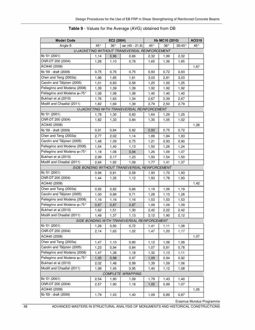
Design Procedures for the Use of EB FRP in Shear Strengthening of Reinforced Concrete Beams
Erasmus Mundus Programme
48 ADVANCED MASTERS IN STRUCTURAL ANALYSIS OF MONUMENTS AND HISTORICAL CONSTRUCTIONS
Table 9 - Values for the Average (AVG) obtained from DB
Model Code ACI318
Angle θ 45° 36° var (45 - 21.8) 45° 36° 35/45° 45°
fib '01 (2001) 1,14 0,96 0,66 2,32 1,99 2,32
CNR-DT 200 (2004) 1,28 1,10 0,78 1,65 1,36 1,65
ACI440 (2008) 1,67
fib '09 - draft (2009) 0,75 0,76 0,75 0,93 0,72 0,93
Chen and Teng (2003a) 1,96 1,85 1,61 3,03 2,81 3,03
Carolin and Täljsten (2005) 1,01 0,83 0,58 1,25 1,00 1,25
Pellegrino and Modena (2008) 1,39 1,39 1,39 1,92 1,92 1,92
Pellegrino and Modena φ=75° 1,08 1,08 1,08 1,40 1,40 1,40
Bukhari et al.(2010) 1,76 1,63 1,34 2,67 2,39 2,67
Modifi and Chaallal (2011) 1,82 1,69 1,39 2,79 2,50 2,79
fib '01 (2001) 1,78 1,30 0,83 1,64 1,29 1,25
CNR-DT 200 (2004) 1,82 1,33 0,84 1,35 1,05 1,02
ACI440 (2008) 1,28
fib '09 - draft (2009) 0,91 0,84 0,92 0,93 0,75 0,72
Chen and Teng (2003a) 2,77 2,02 1,14 1,89 1,84 1,83
Carolin and Täljsten (2005) 1,48 1,09 0,75 1,21 0,93 0,90
Pellegrino and Modena (2008) 1,54 1,40 1,13 1,50 1,26 1,24
Pellegrino and Modena φ=75° 1,18 1,08 0,94 1,26 1,09 1,07
Bukhari et al.(2010) 2,99 2,17 1,23 1,93 1,54 1,50
Modifi and Chaallal (2011) 2,64 1,92 1,09 1,77 1,41 1,37
fib '01 (2001) 0,94 0,81 0,59 1,93 1,70 1,93
CNR-DT 200 (2004) 1,44 1,35 1,12 1,93 1,78 1,93
ACI440 (2008) 1,42
Chen and Teng (2003a) 0,92 0,82 0,66 1,19 1,06 1,19
Carolin and Täljsten (2005) 1,00 0,89 0,71 1,28 1,10 1,28
Pellegrino and Modena (2008) 1,16 1,16 1,16 1,53 1,53 1,53
Pellegrino and Modena φ=75° 0,87 0,87 0,87 1,09 1,09 1,09
Bukhari et al.(2010) 1,62 1,51 1,30 2,42 2,22 2,42
Modifi and Chaallal (2011) 1,49 1,37 1,13 2,12 1,90 2,12
fib '01 (2001) 1,26 0,95 0,72 1,41 1,11 1,08
CNR-DT 200 (2004) 2,14 1,63 1,02 1,47 1,20 1,17
ACI440 (2008) 1,07
Chen and Teng (2003a) 1,47 1,10 0,80 1,12 1,06 1,06
Carolin and Täljsten (2005) 1,23 0,94 0,84 1,07 0,81 0,78
Pellegrino and Modena (2008) 1,47 1,38 1,18 1,32 1,13 1,11
Pellegrino and Modena φ=75° 1,05 0,98 0,97 1,09 0,94 0,92
Bukhari et al.(2010) 2,02 1,48 0,99 1,39 1,09 1,06
Modifi and Chaallal (2011) 1,98 1,45 0,95 1,40 1,12 1,08
fib '01 (2001) 2,54 1,90 1,09 1,79 1,43 1,40
CNR-DT 200 (2004) 2,57 1,90 1,18 1,05 0,99 1,07
ACI440 (2008) 1,05
fib '09 - draft (2009) 1,79 1,43 1,40 1,09 0,89 0,87
COMPLETE WRAPPING
EC2 (2004) fib MC10 (2010)
U-JACKETING WITHOUT TRANSVERSAL REINFORCEMENT
U-JACKETING WITH TRANSVERSAL REINFORCEMENT
SIDE BONDING WITHOUT TRANSVERSAL REINFORCEMENT
SIDE BONDING WITH TRANSVERSAL REINFORCEMENT
Design Procedures for the Use of EB FRP in Shear Strengthening of Reinforced Concrete Beams
Erasmus Mundus Programme
ADVANCED MASTERS IN STRUCTURAL ANALYSIS OF MONUMENTS AND HISTORICAL CONSTRUCTIONS 49
Since basic codes, EC2 (2004) and fib MC10 (2010) are conceptually different in sense that EC2 does not
take into account contribution of both steel and concrete in presence of transversal steel, while fib MC10
does, it was expected gaining different results. It can be observed that for configurations with transversal
steel (U-jacketed and side bonded) and wrapped configurations, in general fib MC10 gives better
predictions, considering both values for CoV and AVG. This indicates once more that both contributions of
concrete and steel should be taken into account, also in presence of steel reinforcement.
In these cases, with presence of transversal steel or wrapped configurations, combination of fib MC10 with
models using angels θ=45° and θ=36° gives better predictions than combination of EC2 with models and
same angels, respectively. Combining EC2 with models and usage of θ=var still gives better results than
combining fib MC10 with models and usage of θ=35/45°, and more over it gives, in general, the best
results considering different basic codes and angels.
As for the angle inside the basic code, θ=var gives the best prediction in case of EC2 as basic code, while
in case of fib MC10 it is not very clear which angle is the most appropriate. On the other hand, taking into
account both values for CoV and AVG, for configurations with transversal steel θ=35/45° gives best
predictions and for configurations without transversal steel θ=36°. This means that in case of EC2 angle
should be taken into account as variable in order to maximize contribution of steel and concrete.
If we analyze values for CoV and AVG in terms of models for strengthened structures, in general, Italian
code CNR-DT200 (2004) and model of Pellegrino and Modena (2008) give good results.
In the overall comparison, considering also modified Pellegrino and Modena model, this model in general
gives the best predictions.
Design Procedures for the Use of EB FRP in Shear Strengthening of Reinforced Concrete Beams
50 ADVANCED MASTERS IN STRUCTURAL ANALYSIS OF MONUMENTS AND HISTORICAL CONSTRUCTIONS
a.
c.
Figure 14 - Best prediction results in general overview: U
transversal steel and side bonded configurations without and with transversal steel (
In Figure 14, graphs are given for best predictions of models, considering different strengthening
configurations.
Design Procedures for the Use of EB FRP in Shear Strengthening of Reinforced Concrete Beams
Erasmus Mundus Programme
ADVANCED MASTERS IN STRUCTURAL ANALYSIS OF MONUMENTS AND HISTORICAL CONSTRUCTIONS
b.
d.
Best prediction results in general overview: U-jacketed configurations without and with
transversal steel and side bonded configurations without and with transversal steel (graphs a,b,c and d
respectively)
, graphs are given for best predictions of models, considering different strengthening
Design Procedures for the Use of EB FRP in Shear Strengthening of Reinforced Concrete Beams
Erasmus Mundus Programme
ADVANCED MASTERS IN STRUCTURAL ANALYSIS OF MONUMENTS AND HISTORICAL CONSTRUCTIONS
jacketed configurations without and with
graphs a,b,c and d,
, graphs are given for best predictions of models, considering different strengthening
Design Procedures for the Use of EB FRP in Shear Strengthening of Reinforced Concrete Beams
Erasmus Mundus Programme
ADVANCED MASTERS IN STRUCTURAL ANALYSIS OF MONUMENTS AND HISTORICAL CONSTRUCTIONS 51
7.3 Results obtained using the RDB
As it was explained before, the most used configuration in practical application is U-jacketed configuration
with transversal steel. Because of this, a Reduced Data Base (RDB) has been made and analyzed. In
Table 10 and Table 11 the main descriptive statistical measures obtained from this analysis are
summarized regarding percentage of conservative predictions, the average (AVG), the standard deviation
(std) and the coefficient of variation (CoV).
In general, usage of basic model code fib MC10 (2010) gives better predictions than usage of EC2,
although still usage of EC2 with θ=var gives the best results considering angle inside basic codes.
It can be observed that design models fib MC10 + fib ’09 – draft with θ=45° and EC2 + modified model of
Pellegrino and Modena (2008) with θ=45° and w=75° give the best predictions, both having the lowest
CoV=0,26. However, a second type of comparison is performed, in which values for AVG were compared
for both models. It has been shown that in overall, modified model of Pellegrino and Modena has value of
AVG closer to one, which makes this prediction more accurate.
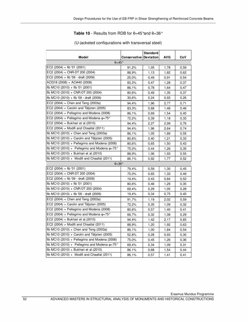
Design Procedures for the Use of EB FRP in Shear Strengthening of Reinforced Concrete Beams
Erasmus Mundus Programme
52 ADVANCED MASTERS IN STRUCTURAL ANALYSIS OF MONUMENTS AND HISTORICAL CONSTRUCTIONS
Table 10 - Results from RDB for θ=45°and θ=36°
(U-jacketed configurations with transversal steel)
Model Conservative
Standard
Deviation AVG CoV
EC2 (2004) + fib '01 (2001) 91,2% 1,05 1,78 0,59
EC2 (2004) + CNR-DT 200 (2004) 88,9% 1,13 1,82 0,62
EC2 (2004) + fib '09 - draft (2009) 25,0% 0,49 0,91 0,54
ACI318 (2008) + ACI440 (2008) 83,3% 0,47 1,28 0,37
fib MC10 (2010) + fib '01 (2001) 86,1% 0,78 1,64 0,47
fib MC10 (2010) + CNR-DT 200 (2004) 80,6% 0,49 1,35 0,37
fib MC10 (2010) + fib '09 - draft (2009) 30,6% 0,24 0,93 0,26
EC2 (2004) + Chen and Teng (2003a) 94,4% 1,96 2,77 0,71
EC2 (2004) + Carolin and Täljsten (2005) 83,3% 0,68 1,48 0,46
EC2 (2004) + Pellegrino and Modena (2008) 86,1% 0,69 1,54 0,45
EC2 (2004) + Pellegrino and Modena φ=75° 72,2% 0,39 1,18 0,33
EC2 (2004) + Bukhari et al.(2010) 94,4% 2,27 2,99 0,76
EC2 (2004) + Modifi and Chaallal (2011) 94,4% 1,96 2,64 0,74
fib MC10 (2010) + Chen and Teng (2003a) 86,1% 1,05 1,89 0,55
fib MC10 (2010) + Carolin and Täljsten (2005) 80,6% 0,40 1,21 0,33
fib MC10 (2010) + Pellegrino and Modena (2008) 80,6% 0,65 1,50 0,43
fib MC10 (2010) + Pellegrino and Modena φ=75° 75,0% 0,44 1,26 0,35
fib MC10 (2010) + Bukhari et al.(2010) 88,9% 1,06 1,93 0,55
fib MC10 (2010) + Modifi and Chaallal (2011) 86,1% 0,92 1,77 0,52
EC2 (2004) + fib '01 (2001) 79,4% 0,59 1,30 0,45
EC2 (2004) + CNR-DT 200 (2004) 75,0% 0,65 1,33 0,49
EC2 (2004) + fib '09 - draft (2009) 19,4% 0,43 0,84 0,52
fib MC10 (2010) + fib '01 (2001) 80,6% 0,46 1,29 0,35
fib MC10 (2010) + CNR-DT 200 (2004) 69,4% 0,29 1,05 0,28
fib MC10 (2010) + fib '09 - draft (2009) 19,4% 0,34 0,75 0,45
EC2 (2004) + Chen and Teng (2003a) 91,7% 1,19 2,02 0,59
EC2 (2004) + Carolin and Täljsten (2005) 72,2% 0,35 1,09 0,32
EC2 (2004) + Pellegrino and Modena (2008) 80,6% 0,57 1,40 0,41
EC2 (2004) + Pellegrino and Modena φ=75° 66,7% 0,32 1,08 0,29
EC2 (2004) + Bukhari et al.(2010) 94,4% 1,42 2,17 0,65
EC2 (2004) + Modifi and Chaallal (2011) 88,9% 1,20 1,92 0,63
fib MC10 (2010) + Chen and Teng (2003a) 86,1% 1,00 1,84 0,54
fib MC10 (2010) + Carolin and Täljsten (2005) 52,8% 0,28 0,93 0,30
fib MC10 (2010) + Pellegrino and Modena (2008) 75,0% 0,45 1,26 0,36
fib MC10 (2010) + Pellegrino and Modena φ=75° 69,4% 0,34 1,09 0,31
fib MC10 (2010) + Bukhari et al.(2010) 86,1% 0,68 1,54 0,44
fib MC10 (2010) + Modifi and Chaallal (2011) 86,1% 0,57 1,41 0,41
θ=45°
θ=36°
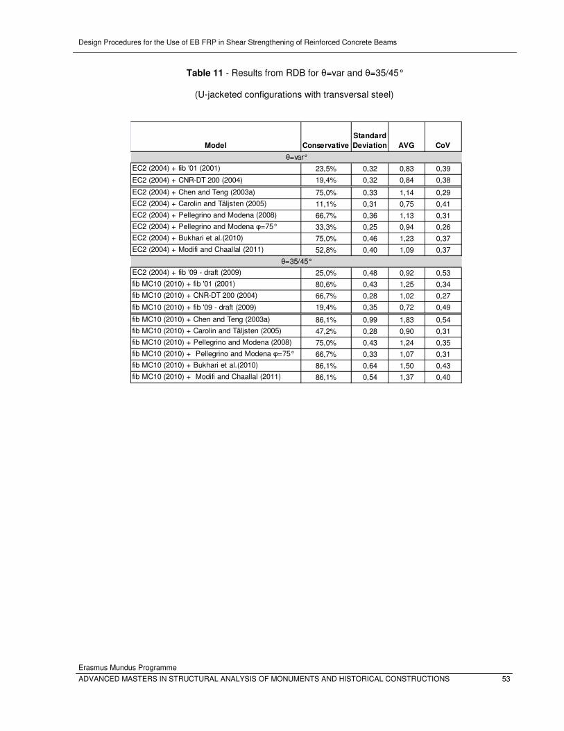
Design Procedures for the Use of EB FRP in Shear Strengthening of Reinforced Concrete Beams
Erasmus Mundus Programme
ADVANCED MASTERS IN STRUCTURAL ANALYSIS OF MONUMENTS AND HISTORICAL CONSTRUCTIONS 53
Table 11 - Results from RDB for θ=var and θ=35/45°
(U-jacketed configurations with transversal steel)
Model Conservative
Standard
Deviation AVG CoV
EC2 (2004) + fib '01 (2001) 23,5% 0,32 0,83 0,39
EC2 (2004) + CNR-DT 200 (2004) 19,4% 0,32 0,84 0,38
EC2 (2004) + Chen and Teng (2003a) 75,0% 0,33 1,14 0,29
EC2 (2004) + Carolin and Täljsten (2005) 11,1% 0,31 0,75 0,41
EC2 (2004) + Pellegrino and Modena (2008) 66,7% 0,36 1,13 0,31
EC2 (2004) + Pellegrino and Modena φ=75° 33,3% 0,25 0,94 0,26
EC2 (2004) + Bukhari et al.(2010) 75,0% 0,46 1,23 0,37
EC2 (2004) + Modifi and Chaallal (2011) 52,8% 0,40 1,09 0,37
EC2 (2004) + fib '09 - draft (2009) 25,0% 0,48 0,92 0,53
fib MC10 (2010) + fib '01 (2001) 80,6% 0,43 1,25 0,34
fib MC10 (2010) + CNR-DT 200 (2004) 66,7% 0,28 1,02 0,27
fib MC10 (2010) + fib '09 - draft (2009) 19,4% 0,35 0,72 0,49
fib MC10 (2010) + Chen and Teng (2003a) 86,1% 0,99 1,83 0,54
fib MC10 (2010) + Carolin and Täljsten (2005) 47,2% 0,28 0,90 0,31
fib MC10 (2010) + Pellegrino and Modena (2008) 75,0% 0,43 1,24 0,35
fib MC10 (2010) + Pellegrino and Modena φ=75° 66,7% 0,33 1,07 0,31
fib MC10 (2010) + Bukhari et al.(2010) 86,1% 0,64 1,50 0,43
fib MC10 (2010) + Modifi and Chaallal (2011) 86,1% 0,54 1,37 0,40
θ=var°
θ=35/45°

Design Procedures for the Use of EB FRP in Shear Strengthening of Reinforced Concrete Beams
Erasmus Mundus Programme
54 ADVANCED MASTERS IN STRUCTURAL ANALYSIS OF MONUMENTS AND HISTORICAL CONSTRUCTIONS
Design Procedures for the Use of EB FRP in Shear Strengthening of Reinforced Concrete Beams
Erasmus Mundus Programme
ADVANCED MASTERS IN STRUCTURAL ANALYSIS OF MONUMENTS AND HISTORICAL CONSTRUCTIONS 55
8. CONCLUSIONS
This work reviews current knowledge on structural behaviour of reinforced concrete (RC) beams
strengthened with composite materials in terms of shear. Performed statically oriented study is
addressing main lacks of building codes recommendations and gives important imputes for further
research in field of the use of FRP in shear strengthening of RC structures.
8.1 Model of Pellegrino and Modena
• This model gives very good predictions in terms of CoV and AVG, since it takes into account
interaction between steel, concrete and FRP.
• It also shows good results while combining both with EC2 (2004) and fib MC10 (2010).
• Modification of the angle characterizing the conventional roughness of the interface w=79° to w=75°, improves model not only in sense of CoV, but also of AVG.
8.2 Basic codes
• For configurations with transversal steel and wrapped, fib MC10 (2010) in general gives better
predictions than EC2 (2004).
• In further investigation, different levels of approximation regarding fib MC10 (2010) should be
analyzed.
• In general, combining fib MC10 (2010) with models using angels θ=45° and θ=36° gives better
predictions than combining EC2 (2004) with models and same angles, respectively.
• Combining EC2 (2004) with models and usage of θ=var still gives better results than combining fib
MC10 (2010) with models and usage of θ=35/45°, and in general, the best results considering
different basic codes.
8.3 Angle inside basic code
• In case of EC2 (2004) as basic code, θ=var gives the best predictions.
• In case of fib MC10 (2010), the best predictions are θ=35/45° and θ=36° for configurations with
and without transversal steel, respectively.

Design Procedures for the Use of EB FRP in Shear Strengthening of Reinforced Concrete Beams
Erasmus Mundus Programme
56 ADVANCED MASTERS IN STRUCTURAL ANALYSIS OF MONUMENTS AND HISTORICAL CONSTRUCTIONS
8.4 Models
• In general, the Italian code CNR-DT200 (2004) and model of Pellegrino and Modena (2008) give
good results
• In the overall comparison, modified Pellegrino and Modena model gives the best predictions.
8.5 U-jacketing with transversal steel configuration
• In general, fib MC10 (2010) gives better predictions than EC2 (2004)
• Considering angle inside basic codes, EC2 (2004) with θ=var gives the best results.
• Combining EC2 (2004) with modified model of Pellegrino and Modena (2008), considering θ=var
and w=75° give the best predictions.
8.6 General conclusions
• In general, usage of EC2 (2004) θ=var gives the best predictions, which indicated great impact of
value of shear crack angle to model predictions.
• Combining EC2 (2004) with modified model of Pellegrino and Modena (2008), considering θ=var
and w=75° in general gives the best predictions for configurations with transversal steel.
• Since model that takes into account interaction between FRP and transversal steel gives (in
general) best predictions, it is proved that this interaction cannot be discarded in design
procedure.
Design Procedures for the Use of EB FRP in Shear Strengthening of Reinforced Concrete Beams
Erasmus Mundus Programme
ADVANCED MASTERS IN STRUCTURAL ANALYSIS OF MONUMENTS AND HISTORICAL CONSTRUCTIONS 57
9. REFERENCES
fib task group 9.3. Externally Bonded FRP Reinforcement for RC Structures (FIB bulletin draft ), 2009.
American Concrete Institute (ACI) Committee 318. "Shear and Torsion." In Building Code Requirements
for Structural Concrete (ACI 318M-08) and Commentary, 167-168. Farmington Hills, MI: American Concrete Institute, 2008.
American Concrete Institute (ACI) Committee 440. "Shear Strengthening." In Guide for the Design and
Construction of Extrenaly Bonded FRP Systems for Strengthening Concrete Structures (ACI 440.2R-08), 34-36. Farmington Hills, MI: American Concrete Institute, 2008.
Barros, J, S Dias, and J Lima. "Efficacy of CFRP-based techniques for the flexural and shear strengthening of concrete beams." Cement & Concrete Composites 29, 2007: 203-217.
Bukhari, I A, R L Vollum, S Ahmad, and J Sagaseta. "Shear strengthening of reinforced concrete." Magazine of Concrete Research 62, 2010: 65-77.
Carolin, A, and B Täljsten. "Theoretical study on strengthening for increased shear bearing capacity." Journal of Composites for Construction 9, 2005: 497-506.
CEN. Eurocode 2: Design of Concrete Structures — Part 1-1: General Rules and Rules for Buildings (ENV
1992-1-1). Brussels: Comite Europeen de Normalisation, 2004.
Chen, G M, J G Teng, and J F Chen. "RC beams shear-strengthened with FRP: shear resistance contributed by FRP." Magazine of Concrete Research 62, No. 4, 2010: 301–311.
Chen, G M, J G Teng, J F Chen, and O A Rosenboom. "Interaction between Steel Stirrups and Shear-Strengthening FRP Strips in RC Beams." Journal of Composites for Construction, Vol. 14, 2010: 498-509.
Chen, J F, and J G Teng. "Shear capacity of FRP-strengthened RC beams: FRP debonding." Construction and Building Materials 17, 2003a: 27–41.
CNR-DT200. Guide for the Design and Construction of Externally Bonded FRP Systems for Strengthening
Existing Structures. Materials, RC and PC Structures, Masonry Structures (CNR- DT 200/2004). Rome: Italian Research Italian Council, Advisory Committee on Technical Recommendations for Construction, 2004.
Colloti, V, and R N Swamy. "Unified analytical approach for determining shear capacity of RC beams strengthened with FRP." Engineering Structures 33, 2011: 827–842.
fib task group 9.3. Externally Bonded FRP Reinforcement for RC Structures (FIB bulletin 14). Lausanne: International Federation for Concrete, fib, 2001.
Gonzales, J. Assesment of Current Standards for Evaluation of Shear FRP Strengthening of Concrete
Beams. Master's Thesis, Padova: University of Padova, 2010.
International Federation for Concrete, fib. "Model Code." 2010.
Design Procedures for the Use of EB FRP in Shear Strengthening of Reinforced Concrete Beams
Erasmus Mundus Programme
58 ADVANCED MASTERS IN STRUCTURAL ANALYSIS OF MONUMENTS AND HISTORICAL CONSTRUCTIONS
Lima, J, and J Barros. "Reliability analysis of shear strengthening externally bonded FRP models." Structures and Buildings, 2011: 43-56.
Modifi, A, and O Chaallal. "Shear Strengthening of RC Beams with EB FRP: Influencing Factors and Conceptual Debonding Model." Journal of Composites for Constructions, 2011: 62-74.
Pellegrino, C, and C Modena. "An Experimentaly Based Analytical Model for the Shear Capacity of FRP-strenghtened Reinforced Concrete Beams." Mechanics of Composite Materialsrials, Vol. 44, No. 3,, 2008: 231-244.
Pellegrino, C, and C Modena. "Fiber-Reinforced Polymer Shear Strengthening of Reinforced Concrete Beams: Experimental Study and Analytical Modeling." ACI Structural Journal, V. 103, No. 5,, 2006.
Pellegrino, C, and C Modena. "FRP Shear Strengthening of RC Beams with Transverse Steel Reinforcement." Journal of Composites for Construction Vol. 6, No. 2,, 2002: 1-8.
Sas, G, B Täljsten, J Barros, J Lima, and A Carolin. "Are Available Models Reliable for Predicting the FRP Contribution to the Shear Resistance of RC Beams?" Journal of Composites for Constructions, 2009: 514-534.