Embed Size (px)
Citation preview
All contents are Copyright © 1992–2012 Cisco Systems, Inc. All rights reserved. This document is Cisco Public Information. Page 1 of 35
CCNA Security
Chapter 10 Lab A: Configuring ASA Basic Settings and Firewall Using CLI (Instructor Version)
Grey Highlighting – indicates answers provided on instructor lab copies only
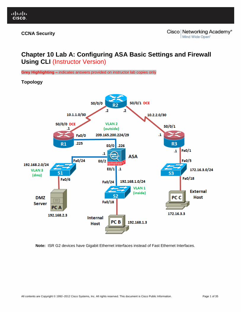
Topology
Note: ISR G2 devices have Gigabit Ethernet interfaces instead of Fast Ethernet Interfaces.

CCNA Security
All contents are Copyright © 1992–2012 Cisco Systems, Inc. All rights reserved. This document is Cisco Public Information. Page 2 of 35
IP Addressing Table
Device
Interface IP Address Subnet Mask Default
Gateway
Switch Port
R1 FA0/0 209.165.200.225 255.255.255.248 N/A ASA E0/0
S0/0/0 (DCE)
10.1.1.1 255.255.255.252 N/A N/A
R2 S0/0/0 10.1.1.2 255.255.255.252 N/A N/A
S0/0/1 (DCE)
10.2.2.2 255.255.255.252 N/A N/A
R3 FA0/1 172.16.3.1 255.255.255.0 N/A S3 FA0/5
S0/0/1 10.2.2.1 255.255.255.252 N/A N/A
ASA VLAN 1 (E0/1)
192.168.1.1 255.255.255.0 NA S2 FA0/24
ASA VLAN 2 (E0/0)
209.165.200.226 255.255.255.248 NA R1 FA0/0
ASA VLAN 3 (E0/2)
192.168.2.1 255.255.255.0 NA S1 FA0/24
PC-A NIC 192.168.2.3 255.255.255.0 192.168.2.1 S1 FA0/6
PC-B NIC 192.168.1.3 255.255.255.0 192.168.1.1 S2 FA0/18
PC-C NIC 172.16.3.3 255.255.255.0 172.16.3.1 S3 FA0/18
Objectives
Part 1: Lab Setup
Cable the network as shown in the topology.
Configure hostnames and interface IP addresses for routers, switches, and PCs.
Configure static routing, including default routes, between R1, R2, and R3.
Configure HTTP and Telnet access for R1.
Verify connectivity between hosts, switches, and routers.
Part 2: Accessing the ASA Console and Using CLI Setup Mode to Configure Basic Settings.
Access the ASA console and view hardware, software, and configuration settings.
Clear previous configuration settings.
Use CLI Setup mode to configure basic settings (hostname, passwords, clock, etc.).
Part 3: Configuring Basic ASA Settings and Interface Security Levels Using CLI.
Configure the hostname and domain name.
Configure the login and enable passwords.
Set the date and time.
Configure the inside and outside interfaces.
Test connectivity to the ASA.
Configure remote management with Telnet.
Configure HTTPS access to the ASA for ASDM.
Part 4: Configuring Routing, Address Translation and Inspection Policy Using CLI.

CCNA Security
All contents are Copyright © 1992–2012 Cisco Systems, Inc. All rights reserved. This document is Cisco Public Information. Page 3 of 35
Configure a static default route for the ASA.
Configure port address translation (PAT) for the inside network.
Modify the MPF application inspection policy.
Part 5: Configuring DHCP, AAA, and SSH.
Configure the ASA as a DHCP server/client.
Configure Local AAA user authentication.
Configure remote management with SSH.
Part 6: Configuring a DMZ, Static NAT, and ACLs
Configure static NAT for the DMZ server.
Configure an ACL on the ASA to allow access to the DMZ for Internet users.
Verify access to the DMZ server for external and internal users.
Background / Scenario
The Cisco Adaptive Security Appliance (ASA) is an advanced network security device that integrates a statefull firewall as well as VPN and other capabilities. This lab employs an ASA 5505 to create a firewall and protect an internal corporate network from external intruders while allowing internal hosts access to the Internet. The ASA creates three security interfaces: Outside, Inside, and DMZ. It provides outside users limited access to the DMZ and no access to inside resources. Inside users can access the DMZ and outside resources.
The focus of this lab is on the configuration of the ASA as a basic firewall. Other devices will receive minimal configuration to support the ASA portion of the lab. This lab uses the ASA CLI, which is similar to the IOS CLI, to configure basic device and security settings.
In part 1 of the lab you configure the topology and non-ASA devices. In Parts 2 through 4 you configure basic ASA settings and the firewall between the inside and outside networks. In part 5 you configure the ASA for additional services such as DHCP, AAA, and SSH. In Part 6 you configure a DMZ on the ASA and provide access to a server in the DMZ.
Your company has one location connected to an ISP. Router R1 represents a CPE device managed by the ISP. Router R2 represents an intermediate Internet router. Router R3 represents an ISP that connects an administrator from a network management company, who has been hired to manage your network remotely. The ASA is an edge CPE security device that connects the internal corporate network and DMZ to the ISP while providing NAT and DHCP services to inside hosts. The ASA will be configured for management by an administrator on the internal network as well as by the remote administrator. Layer 3 VLAN interfaces provide access to the three areas created in the lab: Inside, Outside and DMZ. The ISP has assigned the public IP address space of 209.165.200.224/29, which will be used for address translation on the ASA.
Note: The routers used with this lab are Cisco 1841 with Cisco IOS Release 12.4(20)T (Advanced IP image). The switches are Cisco WS-C2960-24TT-L with Cisco IOS Release 12.2(46)SE (C2960-LANBASEK9-M image). Other routers, switches, and Cisco IOS versions can be used. However, results and output may vary.
The ASA used with this lab is a Cisco model 5505 with an 8-port integrated switch, running OS version 8.4(2) and ASDM version 6.4(5) and comes with a Base license that allows a maximum of three VLANs.
Note: Make sure that the routers and switches have been erased and have no startup configurations.
Instructor Notes:
Instructions for erasing both the switch and router are provided in the Lab Manual, located on Academy Connection in the Tools section. Instructions for erasing the ASA and accessing the console are provided in this lab.

CCNA Security
All contents are Copyright © 1992–2012 Cisco Systems, Inc. All rights reserved. This document is Cisco Public Information. Page 4 of 35
Required Resources
3 routers (Cisco 1841 with Cisco IOS Release 12.4(20)T1 or comparable)
3 switches (Cisco 2960 or comparable)
1 ASA 5505 (OS version 8.4(2) and ASDM version 6.4(5) and Base license or comparable)
PC-A: Windows XP, Vista, or Windows 7 with CCP, PuTTy SSH client
PC-B: Windows XP, Vista, or Windows 7 with PuTTy SSH client (ASDM optional)
PC-C: Windows XP, Vista, or Windows 7 with CCP, PuTTy SSH client
Serial and Ethernet cables as shown in the topology
Rollover cables to configure the routers and ASA via the console
Instructor Notes:
This lab is divided into six parts. Part 1 can be performed separately but must be performed before parts 2 through 6. Part 2 uses the CLI Setup mode. Parts 3 through 6 can be performed individually or in combination with others as time permits, but should be performed sequentially. In some cases, a task assumes the configuration of certain features in a prior task.
The main goal is to use an ASA to implement firewall and other services that might previously have been configured on an ISR. In this lab the student configures the most common basic ASA settings and services, such as NAT, ACL, DHCP, AAA, and SSH.
The final running configurations for all devices are found at the end of the lab. The ASA factory default configuration is also provided.

CCNA Security
All contents are Copyright © 1992–2012 Cisco Systems, Inc. All rights reserved. This document is Cisco Public Information. Page 5 of 35
Part 1: Basic Router/Switch/PC Configuration
In Part 1 of this lab, you set up the network topology and configure basic settings on the routers, such as interface IP addresses and static routing.
Note: Do not configure any ASA settings at this time.
Step 1: Cable the network and clear previous device settings.
Attach the devices that are shown in the topology diagram and cable as necessary. Make sure that the routers and switches have been erased and have no startup configurations.
Step 2: Configure basic settings for routers and switches.
a. Configure host names as shown in the topology for each router.
b. Configure router interface IP addresses as shown in the IP Addressing Table.
c. Configure a clock rate for routers with a DCE serial cable attached to their serial interface. Router R1 is shown here as an example.
R1(config)# interface S0/0/0
R1(config-if)# clock rate 64000
d. Configure the host name for the switches. Other than the host name, the switches can be left in their default configuration state. Configuring the VLAN management IP address for the switches is optional.
Step 3: Configure static routing on the routers.
a. Configure a static default route from R1 to R2 and from R3 to R2.
R1(config)# ip route 0.0.0.0 0.0.0.0 Serial0/0/0
R3(config)# ip route 0.0.0.0 0.0.0.0 Serial0/0/1
b. Configure a static route from R2 to the R1 Fa0/0 subnet (connected to ASA interface E0/0) and a static route from R2 to the R3 LAN.
R2(config)# ip route 209.165.200.224 255.255.255.248 Serial0/0/0
R2(config)# ip route 172.16.3.0 255.255.255.0 Serial0/0/1
Step 4: Enable the HTTP server on R1 and set the enable and vty passwords.
a. Enable HTTP access to R1 using the ip http server command in global config mode. Also set
the console and VTY passwords to cisco. This will provide web and Telnet targets for testing later in the lab.
R1(config)# ip http server
R1(config)# enable password class
R1(config)# line vty 0 4
R1(config-line)# password cisco
R1(config-line)# login
R1(config)# line con 0
R1(config-line)# password cisco
R1(config-line)# login
b. On routers R2 and R3, set the same enable, console and vty passwords as with R1.

CCNA Security
All contents are Copyright © 1992–2012 Cisco Systems, Inc. All rights reserved. This document is Cisco Public Information. Page 6 of 35
Step 5: Configure PC host IP settings.
Configure a static IP address, subnet mask, and default gateway for PC-A, PC-B, and PC-C as shown in the IP Addressing Table.
Step 6: Verify connectivity.
Because the ASA is the focal point for the network zones and it has not yet been configured, there will be no connectivity between devices that are connected to it. However, PC-C should be able to ping the R1 interface. From PC-C, ping the R1 Fa0/0 IP address (209.165.200.225). If these pings are not successful, troubleshoot the basic device configurations before continuing.
Note: If you can ping from PC-C to R1 Fa0/0 and S0/0/0 you have demonstrated that static routing is configured and functioning correctly.
Step 7: Save the basic running configuration for each router and switch.
Part 2: Accessing the ASA Console and Using Setup to Configure Basic Settings
In Part 2 of this lab, you will access the ASA via the console and use various show commands to determine hardware, software, and configuration settings. You will clear the current configuration and use the CLI interactive Setup utility to configure basic ASA settings.
Note: Do not configure any ASA settings at this time.
Step 1: Access the ASA Console.
a. Accessing the ASA via the console port is the same as with a Cisco router or switch. Connect to the ASA console port with a rollover cable.
b. Use a terminal emulation program such as TeraTerm or HyperTerminal to access the CLI. Then use the serial port settings of 9600 baud, eight data bits, no parity, one stop bit, and no flow control.
c. Enter privileged mode with the enable command and password (if set). By default the password is
blank so you can just press Enter. If the password has been changed to that specified in this lab,
enter the word class. The default ASA hostname and prompt is ciscoasa>.
ciscoasa> enable
Password: class (or press Enter if none set)
Step 2: Determine the ASA version, interfaces, and license.
The ASA 5505 comes with an integrated 8-port Ethernet switch. Ports E0/0 though E0/5 are normal Fast Ethernet ports and ports E0/6 and E0/7 are PoE ports for use with PoE devices such as IP phones or network cameras.
a. Use the show version command to determine various aspects of this ASA device.
ciscoasa# show version
Cisco Adaptive Security Appliance Software Version 8.4(2)
Device Manager Version 6.4(5)
Compiled on Wed 15-Jun-11 18:17 by builders
System image file is "disk0:/asa842-k8.bin"
Config file at boot was "startup-config"
ciscoasa up 23 hours 0 mins

CCNA Security
All contents are Copyright © 1992–2012 Cisco Systems, Inc. All rights reserved. This document is Cisco Public Information. Page 7 of 35
Hardware: ASA5505, 512 MB RAM, CPU Geode 500 MHz
Internal ATA Compact Flash, 128MB
BIOS Flash M50FW016 @ 0xfff00000, 2048KB
Encryption hardware device : Cisco ASA-5505 on-board accelerator (revision 0x0)
Boot microcode : CN1000-MC-BOOT-2.00
SSL/IKE microcode : CNLite-MC-SSLm-PLUS-2.03
IPSec microcode : CNlite-MC-IPSECm-MAIN-2.06
Number of accelerators: 1
0: Int: Internal-Data0/0 : address is 0007.7dbf.5645, irq 11
1: Ext: Ethernet0/0 : address is 0007.7dbf.563d, irq 255
2: Ext: Ethernet0/1 : address is 0007.7dbf.563e, irq 255
<output omitted>
What software version is this ASA running? The ASA in this lab uses version 8.4(2).
What is the name of the system image file and from where was it loaded? The system image file in the ASA for this lab is asa842-k8.bin and it was loaded from disk0: (or flash:).
The ASA can be managed using a built-in GUI known as the Adaptive Security Device Manager (ASDM). What version of ASDM is this ASA running? The ASA in this lab uses ASDM version 6.4(5).
How much RAM does this ASA have? The ASA in this lab has 512 MB RAM.
How much flash memory does this ASA have? The ASA in this lab has 128 MB RAM.
How many Ethernet ports does this ASA have? The ASA in this lab has 8 ports.
What type of license does this ASA have? Either Base or the Security Plus license.
How many VLANs can be created with this license? Three VLANs with the Base license or 20 with the Security Plus license.
Instructor Note: Although 3 VLANs are possible, the DMZ feature has a restriction placed on it that limits communication between the third named VLAN and one of the other two VLANs. This will be explained further and configured in Part 6 of this lab.
Step 3: Determine the file system and contents of flash memory.
a. Display the ASA file system using the show file system command to determine what prefixes are
supported.
ciscoasa# show file system
File Systems:
Size(b) Free(b) Type Flags Prefixes
* 128573440 55664640 disk rw disk0: flash:
- - network rw tftp:
- - opaque rw system:
- - network ro http:
- - network ro https:
- - network rw ftp:
- - network rw smb:
What is another name for flash:? Disk0:
b. Display the contents of flash memory using one of these commands: show flash, show disk0,
dir flash: or dir disk0:
ciscoasa# show flash:
--#-- --length-- -----date/time------ path

CCNA Security
All contents are Copyright © 1992–2012 Cisco Systems, Inc. All rights reserved. This document is Cisco Public Information. Page 8 of 35
168 25159680 Aug 29 2011 13:00:52 asa842-k8.bin
122 0 Aug 29 2011 13:09:32 nat_ident_migrate
13 2048 Aug 29 2011 13:02:14 coredumpinfo
14 59 Aug 29 2011 13:02:14 coredumpinfo/coredump.cfg
169 16280544 Aug 29 2011 13:02:58 asdm-645.bin
3 2048 Aug 29 2011 13:04:42 log
6 2048 Aug 29 2011 13:05:00 crypto_archive
171 34816 Jan 01 1980 00:00:00 FSCK0000.REC
173 36864 Jan 01 1980 00:00:00 FSCK0001.REC
174 12998641 Aug 29 2011 13:09:22 csd_3.5.2008-k9.pkg
175 2048 Aug 29 2011 13:09:24 sdesktop
211 0 Aug 29 2011 13:09:24 sdesktop/data.xml
176 6487517 Aug 29 2011 13:09:26 anyconnect-macosx-i386-2.5.2014-k9.pkg
177 6689498 Aug 29 2011 13:09:30 anyconnect-linux-2.5.2014-k9.pkg
178 4678691 Aug 29 2011 13:09:32 anyconnect-win-2.5.2014-k9.pkg
<output omitted>
What is the name of the ASDM file in flash:? asdm-645.bin
Instructor Notes: Check the contents of flash memory occasionally to see if there are many upgrade_startup_error log files. The ASA generates these as a result of erasing the startup config. You can delete these by issuing the command del
flash:upgrade_startup_errors* from the Enable prompt and pressing enter at each prompt.
CCNAS-ASA# del flash:upgrade_startup_errors*
Delete filename [upgrade_startup_errors*]?
Delete disk0:/upgrade_startup_errors_201109141157.log? [confirm] <enter>
Delete disk0:/upgrade_startup_errors_201109141224.log? [confirm] <enter>
<output omitted>
Step 4: Determine the current running configuration.
The ASA 5505 is commonly used as an edge security device that connects a small business or teleworker to an ISP device, such as a DSL or cable modem, for access to the Internet. The default factory configuration for the ASA 5505 includes the following:
An inside VLAN 1 interface is configured that includes the Ethernet 0/1 through 0/7 switch ports. The VLAN 1 IP address and mask are 192.168.1.1 and 255.255.255.0.
An outside VLAN 2 interface is configured that includes the Ethernet 0/0 switch port. By default, VLAN 2 derives its IP address from the ISP using DHCP.
The default route is also derived from the DHCP default gateway.
All inside IP addresses are translated when accessing the outside, using interface PAT on the VLAN 2 interface.
By default, inside users can access the outside with an access list, and outside users are prevented from accessing the inside.
The DHCP server is enabled on the security appliance, so a PC connecting to the VLAN 1 interface receives an address between 192.168.1.5 and 192.168.1.36 (base license), though the actual range may vary.
The HTTP server is enabled for ASDM and is accessible to users on the 192.168.1.0/24 network.
No console or enable passwords are required and the default host name is ciscoasa.
Note: In this lab you will manually configure settings similar to those listed above, as well as some additional ones, using the ASA CLI.

CCNA Security
All contents are Copyright © 1992–2012 Cisco Systems, Inc. All rights reserved. This document is Cisco Public Information. Page 9 of 35
a. Display the current running configuration using the show running-config command.
ciscoasa# show running-config
: Saved
:
ASA Version 8.4(2)
!
hostname ciscoasa
enable password 8Ry2YjIyt7RRXU24 encrypted
passwd 2KFQnbNIdI.2KYOU encrypted
names
!
interface Ethernet0/0
switchport access vlan 2
!
interface Ethernet0/1
!
interface Ethernet0/2
<output omitted>
Note: To stop the output from a command using the CLI, press the letter Q.
If you see VLANs 1 and 2 and other settings as described previously, the device is most likely configured with the default factory configuration. You may also see other security features such as a global policy that inspects selected application traffic, which the ASA inserts by default, if the original startup configuration has been erased. The actual output will vary depending on the ASA model, version and configuration status.
b. You can restore the ASA to its factory default settings by using the command configure
factory-default as shown here.
ciscoasa# conf t
ciscoasa(config)# configure factory-default
WARNING: The boot system configuration will be cleared.
The first image found in disk0:/ will be used to boot the
system on the next reload.
Verify there is a valid image on disk0:/ or the system will
not boot.
Begin to apply factory-default configuration:
Clear all configuration
WARNING: DHCPD bindings cleared on interface 'inside', address pool removed
Executing command: interface Ethernet 0/0
Executing command: switchport access vlan 2
Executing command: no shutdown
Executing command: exit
Executing command: interface Ethernet 0/1
Executing command: switchport access vlan 1
Executing command: no shutdown
Executing command: exit
<output omitted>
c. Review this output and pay particular attention to the VLAN interfaces, and NAT and DHCP related sections. These will be configured later in this lab using the CLI.
d. You may wish to capture and print the factory-default configuration as a reference. Use the terminal emulation program to copy it from the ASA and paste it into a text document. You can then edit this file, if desired, so that it contains only valid commands. You should also remove password commands and enter the no shut command to bring up the desired interfaces.

CCNA Security
All contents are Copyright © 1992–2012 Cisco Systems, Inc. All rights reserved. This document is Cisco Public Information. Page 10 of 35
Step 5: Clear the previous ASA configuration settings.
a. Use the write erase command to remove the startup-config file from flash memory.
ciscoasa# write erase
Erase configuration in flash memory? [confirm]
[OK]
ciscoasa#
ciscoasa# show start
No Configuration
Note: The IOS command erase startup-config is not supported on the ASA.
b. Use the reload command to restart the ASA. This will cause the ASA to come up in CLI Setup
mode. If prompted that the config has been modified, asking if you want to save it, respond “N”.
ciscoasa# reload
Proceed with reload? [confirm]
ciscoasa#
***
*** --- START GRACEFUL SHUTDOWN ---
Shutting down isakmp
Shutting down File system
***
*** --- SHUTDOWN NOW ---
Process shutdown finished
Rebooting.....
CISCO SYSTEMS
Embedded BIOS Version 1.0(12)13 08/28/08 15:50:37.45
<output omitted>
Step 6: Use the Setup interactive CLI mode to configure basic settings.
When the ASA completes the reload process, it should detect that the startup-config file is missing and present a series of interactive prompts to configure basic ASA settings. If it does not come up in this mode, repeat Step 5. As an alternative, you can run the setup command at the global configuration
prompt, but you must first create a VLAN interface (VLAN 1), name the VLAN “management” (using the nameif command), and assign the VLAN an IP address.
Note: The interactive prompt mode does not configure the ASA with factory defaults as described in Step 4. This mode can be used to configure minimal basic settings such as host name, clock, passwords, etc. You can also bypass this mode and go directly to the CLI in order to configure the ASA settings, as described in Part 3 of this lab.
a. Respond to the Setup interactive prompts as shown here, after the ASA reloads.
Pre-configure Firewall now through interactive prompts [yes]? <enter>
Firewall Mode [Routed]: <enter>
Enable password [<use current password>]: cisco
Allow password recovery [yes]? <enter>
Clock (UTC):
Year [2011]: <enter>
Month [Oct]: <enter>
Day [01]: <enter>
Time [12:24:42]: <enter>
Management IP address: 192.168.1.1 <enter>
Management network mask: 255.255.255.0 <enter>
Host name: ASA-Init
Domain name: generic.com
IP address of host running Device Manager: <enter>
The following configuration will be used:
Enable password: cisco

CCNA Security
All contents are Copyright © 1992–2012 Cisco Systems, Inc. All rights reserved. This document is Cisco Public Information. Page 11 of 35
Allow password recovery: yes
Clock (UTC): 12:24:42 Sep 25 2011
Firewall Mode: Routed
Management IP address: 192.168.1.1
Management network mask: 255.255.255.0
Host name: ASA-Init
Domain name: generic.com
IP address of host running Device Manager: <enter>
Use this configuration and write to flash? yes
INFO: Security level for "management" set to 0 by default.
WARNING: http server is not yet enabled to allow ASDM access.
Cryptochecksum: c8a535f0 e273d49e 5bddfd19 e12566b1
2070 bytes copied in 0.940 secs
Type help or '?' for a list of available commands.
ASA-Init#
Note: In the above configuration, the IP address of the host running ASDM was left blank. It is not necessary to install ASDM on a host. It can be run from the flash memory of the ASA device itself using the browser of the host. This process is described in Chapter 10 Lab B, Configuring ASA Basic Settings and Firewall Using ASDM. You may also see the warning above stating that the ASA HTTP server has not yet been enabled. This will be done in a subsequent step.
Note: The responses to the prompts are automatically stored in the startup-config and the running config. However, additional security related commands, such as a global default inspection service policy, are inserted into the running-config by the ASA OS.
b. Issue the show run command to see the additional security related configuration commands that are
inserted by the ASA.
c. Issue the copy run start command to capture the additional security related commands in the
startup-config.
d. Issue the reload command to restart the ASA and load the startup configuration.
ASA-Init# reload
Proceed with reload? [confirm] <enter>
<output omitted>
e. Enter privileged EXEC mode with the enable command. Provide the password set in Step 6a
(cisco). Issue the show running-config command. You should see the entries you provided in
the interactive configuration process.
Part 3: Configuring ASA Settings and Interface Security Using the CLI
In Part 3 of this lab, you configure basic settings by using the ASA CLI, even though some of them were already configured using the Setup mode interactive prompts in Part 2. In this part you start with the settings configured in Part 2 and add to or modify them to create a more complete basic configuration.
Tip: You will find that many ASA CLI commands are similar to if not the same as those used with Cisco IOS CLI. In addition, moving between configuration modes and submodes is essentially the same.
Note: You must complete Part 2 before beginning Part 3.

CCNA Security
All contents are Copyright © 1992–2012 Cisco Systems, Inc. All rights reserved. This document is Cisco Public Information. Page 12 of 35
Step 1: Configure the hostname and domain name.
a. Enter Global configuration mode using the config t command. The first time you enter
configuration mode after running Setup you will be asked if you wish to enable anonymous reporting. Respond with “no”.
ASA-Init# conf t
ASA-Init(config)#
***************************** NOTICE *****************************
Help to improve the ASA platform by enabling anonymous reporting,
which allows Cisco to securely receive minimal error and health
information from the device. To learn more about this feature,
please visit: http://www.cisco.com/go/smartcall
Would you like to enable anonymous error reporting to help improve
the product? [Y]es, [N]o, [A]sk later: n
In the future, if you would like to enable this feature,
issue the command "call-home reporting anonymous".
Please remember to save your configuration.
b. Configure the ASA host name using the hostname command.
ASA-Init(config)# hostname CCNAS-ASA
c. Configure the domain name using the domain-name command.
CCNAS-ASA(config)# domain-name ccnasecurity.com
Step 2: Configure the login and enable mode passwords.
a. The login password is used for Telnet connections (and SSH prior to ASA version 8.4). By default it is set to cisco. You can change the login password using the passwd or password command. For this
lab leave it set to the default of cisco.
b. Configure the privileged EXEC mode (enable) password using the enable password command.
CCNAS-ASA(config)# enable password class
Step 3: Set the date and time.
a. The date and time can be set manually using the clock set command. The syntax for the clock set
command is clock set hh:mm:ss {month day | day month} year. The following is an
example of how to set the date and time using a 24-hour clock.
CCNAS-ASA(config)# clock set 14:25:00 october 1 2011
Step 4: Configure the inside and outside interfaces.
ASA 5505 interface notes: The 5505 is different from the other 5500 series ASA models. With other ASAs, the physical port can be assigned a Layer 3 IP address directly, much like a Cisco router. With the ASA 5505, the eight integrated switch ports are Layer 2 ports. To assign Layer 3 parameters, you must create a switch virtual interface (SVI) or logical VLAN interface and then assign one or more of the physical layer 2 ports to it. All 8 switch ports are initially assigned to VLAN 1, unless the factory default config is present, in which case port E0/0 is assigned to VLAN 2. In this step you create internal and external VLAN interfaces, name them, assign IP addresses, and set the interface security level. If you completed the initial configuration Setup utility, interface VLAN 1 is configured as the management VLAN with an IP address of 192.168.1.1. You will configure it as the inside interface for this lab. You will

CCNA Security
All contents are Copyright © 1992–2012 Cisco Systems, Inc. All rights reserved. This document is Cisco Public Information. Page 13 of 35
only configure the VLAN 1 (inside) and VLAN 2 (outside) interfaces at this time. The VLAN 3 (dmz) interface will be configured in Part 6 of the lab.
a. Configure a logical VLAN 1 interface for the inside network, 192.168.1.0/24, and set the security level to the highest setting of 100.
CCNAS-ASA(config)# interface vlan 1
CCNAS-ASA(config-if)# nameif inside
CCNAS-ASA(config-if)# ip address 192.168.1.1 255.255.255.0
CCNAS-ASA(config-if)# security-level 100
b. Create a logical VLAN 2 interface for the outside network, 209.165.200.224/29, set the security level to the lowest setting of 0 and bring up the VLAN 2 interface.
CCNAS-ASA(config-if)# interface vlan 2
CCNAS-ASA(config-if)# nameif outside
INFO: Security level for "outside" set to 0 by default.
CCNAS-ASA(config-if)# ip address 209.165.200.226 255.255.255.248
CCNAS-ASA(config-if)# no shutdown
Interface security level notes: You may receive a message that the security level for the inside interface was set automatically to 100 and the outside interface was set to 0. The ASA uses interface security levels from 0 to 100 to enforce the security policy. Security Level 100 (inside) is the most secure and level 0 (outside) is the least secure. By default, the ASA applies a policy where traffic from a higher security level interface to one with a lower level is permitted and traffic from a lower security level interface to one with a higher security level is denied. The ASA default security policy permits outbound traffic, which is inspected by default. Returning traffic is allowed because of statefull packet inspection. This default “routed mode” firewall behavior of the ASA allows packets to be routed from the inside network to the outside network but not vice versa. In Part 4 of this lab you will configure NAT to increase the firewall protection.
c. Use the show interface command to ensure that ASA Layer 2 ports E0/0 (for VLAN 2) and E0/1 (for
VLAN 1) are both up. An example is shown for E0/0. If either port is shown as down/down, check the physical connections. If either port is administratively down, bring it up with the no shutdown command.
CCNAS-ASA# show interface e0/0
Interface Ethernet0/0 "", is administratively down, line protocol is up
Hardware is 88E6095, BW 100 Mbps, DLY 100 usec
Auto-Duplex(Full-duplex), Auto-Speed(100 Mbps)
<output omitted>
d. Assign ASA Layer 2 port E0/1 to VLAN 1 and port E0/0 to VLAN 2 and use the no shutdown command
to ensure they are up.
CCNAS-ASA(config)# interface e0/1
CCNAS-ASA(config-if)# switchport access vlan 1
CCNAS-ASA(config-if)# no shutdown
CCNAS-ASA(config-if)# interface e0/0
CCNAS-ASA(config-if)# switchport access vlan 2
CCNAS-ASA(config-if)# no shutdown
Note: Even though E0/1 is in VLAN 1 by default, the commands are provided above.

CCNA Security
All contents are Copyright © 1992–2012 Cisco Systems, Inc. All rights reserved. This document is Cisco Public Information. Page 14 of 35
e. Display the status for all ASA interfaces using the show interface ip brief command. Note that
this command is different from the IOS command show ip interface brief. If any of the physical or
logical interfaces previously configured are not UP/UP, troubleshoot as necessary before continuing.
Tip: Most ASA show commands, as well as ping, copy and others, can be issued from within any config mode prompt without the “do” command required with IOS.
CCNAS-ASA(config)# show interface ip brief
Interface IP-Address OK? Method Status Protocol
Ethernet0/0 unassigned YES unset up up
Ethernet0/1 unassigned YES unset up up
Ethernet0/2 unassigned YES unset up up
Ethernet0/3 unassigned YES unset down down
Ethernet0/4 unassigned YES unset down down
Ethernet0/5 unassigned YES unset down down
Ethernet0/6 unassigned YES unset down down
Ethernet0/7 unassigned YES unset down down
Internal-Data0/0 unassigned YES unset up up
Internal-Data0/1 unassigned YES unset up up
Vlan1 192.168.1.1 YES manual up up
Vlan2 209.165.200.226 YES manual up up
Virtual0 127.0.0.1 YES unset up up
f. Display the information for the Layer 3 VLAN interfaces using the show ip address command.
CCNAS-ASA(config)# show ip address
System IP Addresses:
Interface Name IP address Subnet mask Method
Vlan1 inside 192.168.1.1 255.255.255.0 manual
Vlan2 outside 209.165.200.226 255.255.255.248 manual
Current IP Addresses:
Interface Name IP address Subnet mask Method
Vlan1 inside 192.168.1.1 255.255.255.0 manual
Vlan2 outside 209.165.200.226 255.255.255.248 manual
g. Use the show switch vlan command to display the inside and outside VLANs configured on the ASA
and to display the assigned ports.
CCNAS-ASA# show switch vlan
VLAN Name Status Ports
---- -------------------------------- --------- -----------------------------
1 inside up Et0/1, Et0/2, Et0/3, Et0/4
Et0/5, Et0/6, Et0/7
2 outside up Et0/0
h. You may also use the command show running-config interface type/number to display the
configuration for a particular interface from the running-config.
CCNAS-ASA# show run interface vlan 1
!
interface Vlan1
nameif inside
security-level 100
ip address 192.168.1.1 255.255.255.0

CCNA Security
All contents are Copyright © 1992–2012 Cisco Systems, Inc. All rights reserved. This document is Cisco Public Information. Page 15 of 35
Step 5: Test connectivity to the ASA.
a. Ensure that PC-B has a static IP address of 192.168.1.3 along with subnet mask 255.255.255.0 and default gateway 192.168.1.1 (the IP address of ASA VLAN 1 inside interface).
b. You should be able to ping from PC-B to the ASA inside interface address and ping from the ASA to PC-B. If the pings fail, troubleshoot the configuration as necessary.
CCNAS-ASA# ping 192.168.1.3
Type escape sequence to abort.
Sending 5, 100-byte ICMP Echos to 192.168.1.3, timeout is 2 seconds:
!!!!!
Success rate is 100 percent (5/5), round-trip min/avg/max = 1/1/1 ms
c. From PC-B, ping the VLAN 2 (outside) interface at IP address 209.165.200.226. You should not be able to ping this address.
d. From PC-B, telnet to the ASA using address 192.168.1.1. Were you able to make the connection? Why or why not? No. The ASA has not been configured to accept Telnet connections.
Step 6: Configure Telnet access to the ASA from the inside network.
a. You can configure the ASA to accept Telnet connections from a single host or a range of hosts on the inside network. Configure the ASA to allow Telnet connections from any host on the inside network 192.168.1.0/24 and set the Telnet timeout to 10 minutes (the default is 5 minutes).
CCNAS-ASA(config)# telnet 192.168.1.0 255.255.255.0 inside
CCNAS-ASA(config)# telnet timeout 10
b. From PC-B, telnet to the ASA using address 192.168.1.1 to verify the Telnet access. Use the remote access login password cisco to access the ASA CLI prompt. Exit the Telnet session using the quit
command.
Note: You cannot use Telnet to the lowest security interface (outside) from the outside unless you use Telnet inside an IPsec tunnel. Telnet is not the preferred remote access tool because of its lack of encryption. In Part 5 of this lab you will configure SSH access from the internal and external network.
Step 7: Configure ASDM access to the ASA.
a. You can configure the ASA to accept HTTPS connections using the http command. This allows
access to the ASA GUI (ASDM). Configure the ASA to allow HTTPS connections from any host on the inside network 192.168.1.0/24.
CCNAS-ASA(config)# http server enable
CCNAS-ASA(config)# http 192.168.1.0 255.255.255.0 inside
b. Open a browser on PC-B and test the HTTPS access to the ASA by entering https://192.168.1.1. You will be prompted with a security certificate warning. Click Continue to this website. Click Yes for the other security warnings. You should see the Cisco ASDM-IDM Launcher where you can enter a username and password. Leave the username blank and enter the password cisco, which was configured when you ran the Setup utility.
Note: Be sure to specify the HTTPS protocol in the URL.
c. Close the browser. In the next lab, you will use ASDM extensively to configure the ASA. The objective here is not to use the ASDM configuration screens, but to verify HTTP/ASDM connectivity to the ASA. If you are unable to access ASDM, check your configurations or contact your instructor or do both.

CCNA Security
All contents are Copyright © 1992–2012 Cisco Systems, Inc. All rights reserved. This document is Cisco Public Information. Page 16 of 35
Part 4: Configuring Routing, Address Translation and Inspection Policy Using the CLI.
In Part 4 of this lab, you provide a default route for the ASA to reach external networks. You configure address translation using network objects to enhance firewall security. You then modify the default application inspection policy to allow specific traffic.
Note: You must complete Part 3 before going on to Part 4.
Step 1: Configure a static default route for the ASA.
In Part 3, you configured the ASA outside interface with a static IP address and subnet mask. However, the ASA does not have a gateway of last resort defined. To enable the ASA to reach external networks, you will configure a default static route on the ASA outside interface.
Note: If the ASA outside interface were configured as a DHCP client, it could obtain a default gateway IP address from the ISP. However, in this lab, the outside interface is configured with a static address.
a. Ping from the ASA to R1 Fa0/0 IP address 209.165.200.225. Was the ping successful? Yes, 209.165.200.224/248 is a directly connected network for both R1 and the ASA.
b. Ping from the ASA to R1 S0/0/0 IP address 10.1.1.1. Was the ping successful? No, the ASA does not have a route to 10.1.1.0/30.
c. Create a “quad zero” default route using the route command, associate it with the ASA outside
interface, and point to the R1 Fa0/0 IP address 209.165.200.225 as the gateway of last resort. The default administrative distance is 1 by default.
CCNAS-ASA(config)# route outside 0.0.0.0 0.0.0.0 209.165.200.225
d. Issue the show route command to display the ASA routing table and the static default route just
created.
CCNAS-ASA# show route
Codes: C - connected, S - static, I - IGRP, R - RIP, M - mobile, B - BGP
D - EIGRP, EX - EIGRP external, O - OSPF, IA - OSPF inter area
N1 - OSPF NSSA external type 1, N2 - OSPF NSSA external type 2
E1 - OSPF external type 1, E2 - OSPF external type 2, E - EGP
i - IS-IS, L1 - IS-IS level-1, L2 - IS-IS level-2, ia - IS-IS inter area
* - candidate default, U - per-user static route, o - ODR
P - periodic downloaded static route
Gateway of last resort is 209.165.200.225 to network 0.0.0.0
C 192.168.10.0 255.255.255.0 is directly connected, inside
C 209.165.200.224 255.255.255.248 is directly connected, outside
S* 0.0.0.0 0.0.0.0 [1/0] via 209.165.200.225, outside
e. Ping from the ASA to R1 S0/0/0 IP address 10.1.1.1. Was the ping successful? Yes. The ASA now has a default route to unknown networks.
Step 2: Configure address translation using PAT and network objects.
Instructor Notes:
Pre-ASA 8.3 NAT configuration:
Prior to ASA version 8.3, NAT configuration from the CLI had been the same as the older PIX firewalls. Configuration was done using the nat, global and static commands. These commands have been

CCNA Security
All contents are Copyright © 1992–2012 Cisco Systems, Inc. All rights reserved. This document is Cisco Public Information. Page 17 of 35
deprecated with 8.3 and newer versions and are no longer supported, with the exception of the nat
command under certain circumstances.
An example of configuring PAT using the old commands is presented here for historical reference. In the example, inside addresses from the 192.168.1.0/24 network are being translated using the address of the outside interface.
If you use the older commands as shown in the example with ASA version 8.3 and newer you get the error result shown here.
CCNAS-ASA(config)# nat (inside) 1 192.168.10.0 255.255.255.0
ERROR: This syntax of nat command has been deprecated.
Please refer to "help nat" command for more details.
CCNAS-ASA(config)# global (outside) 1 interface
ERROR: This syntax of nat command has been deprecated.
Please refer to "help nat" command for more details.
Note: Beginning with ASA version 8.3, network objects are used to configure all forms of NAT. A network object is created and it is within this object that NAT is configured. In Step 2a a network object inside-net is used to translate the inside network addresses 192.168.10.0/24 to the global address of the outside ASA interface. This type of object configuration is called Auto-NAT.
a. Create network object inside-net and assign attributes to it using the subnet and nat commands. In
version 8.3 and newer only the nat command is used and the static and global commands are
no longer supported.
CCNAS-ASA(config)# object network inside-net
CCNAS-ASA(config-network-object)# subnet 192.168.1.0 255.255.255.0
CCNAS-ASA(config-network-object)# nat (inside,outside) dynamic interface
CCNAS-ASA(config-network-object)# end
b. The ASA splits the configuration into the object portion that defines the network to be translated and the actual nat command parameters. These appear in two different places in the running-config.
Display the NAT object configuration using the show run object and show run nat commands.
CCNAS-ASA# show run object
object network inside-net
subnet 192.168.1.0 255.255.255.0
CCNAS-ASA# show run nat
!
object network inside-net
nat (inside,outside) dynamic interface
c. From PC-B attempt to ping the R1 Fa0/0 interface at IP address 209.165.200.225. Were the pings successful? No.
d. Issue the show nat command on the ASA to see the translated and untranslated hits. Notice that, of
the pings from PC-B, 4 were translated and 4 were not. This is due to the fact that that ICMP is not being inspected by the global inspection policy. The outgoing pings (echos) were translated, the returning echo replies were blocked by the firewall policy. You will configure the default inspection policy to allow ICMP in the next step.
CCNAS-ASA# show nat
Auto NAT Policies (Section 2)
1 (inside) to (outside) source dynamic inside-net interface
translate_hits = 4, untranslate_hits = 4

CCNA Security
All contents are Copyright © 1992–2012 Cisco Systems, Inc. All rights reserved. This document is Cisco Public Information. Page 18 of 35
e. Ping from PC-B to R1 again and quickly issue the show xlate command to see the actual
addresses being translated.
CCNAS-ASA# show xlate
1 in use, 28 most used
Flags: D - DNS, i - dynamic, r - portmap, s - static, I - identity, T - twice
ICMP PAT from inside:192.168.1.3/512 to outside:209.165.200.226/21469 flags ri idle
0:00:03 timeout 0:00:30
Note: The flags (r and i) indicate that the translation was based on a port map (r) and was done dynamically (i).
f. Open a browser on PC-B and enter the IP address of R1 Fa0/0 (209.165.200.225). You should be prompted by R1 for SDM or CCP GUI login. TCP-based HTTP traffic is permitted by default by the firewall inspection policy.
g. On the ASA use the show nat and show xlate commands again to see the hits and addresses
being translated for the HTTP connection.
Step 3: Modify the default MPF application inspection global service policy.
For application layer inspection, as well as other advanced options, the Cisco Modular Policy Framework (MPF) is available on ASAs. Cisco MPF uses three configuration objects to define modular, object-oriented, hierarchical policies:
Class maps: Define a match criterion
Policy maps: Associate actions to the match criteria
Service policies: Attach the policy map to an interface, or globally to all interfaces of the appliance.
a. Display the default MPF policy map that performs the inspection on inside-to-outside traffic. Only traffic that was initiated from the inside is allowed back in to the outside interface. Notice that the ICMP protocol is missing.
CCNAS-ASA# show run
<output omitted>
class-map inspection_default
match default-inspection-traffic
!
policy-map type inspect dns preset_dns_map
parameters
message-length maximum client auto
message-length maximum 512
policy-map global_policy
class inspection_default
inspect dns preset_dns_map
inspect ftp
inspect h323 h225
inspect h323 ras
inspect ip-options
inspect netbios
inspect rsh
inspect rtsp
inspect skinny
inspect esmtp
inspect sqlnet
inspect sunrpc
inspect tftp
inspect sip
inspect xdmcp
!
service-policy global_policy global

CCNA Security
All contents are Copyright © 1992–2012 Cisco Systems, Inc. All rights reserved. This document is Cisco Public Information. Page 19 of 35
b. Add the inspection of ICMP traffic to the policy map list using the following commands:
CCNAS-ASA(config)# policy-map global_policy
CCNAS-ASA(config-pmap)# class inspection_default
CCNAS-ASA(config-pmap-c)# inspect icmp
c. From PC-B attempt to ping the R1 Fa0/0 interface at IP address 209.165.200.225. The pings should be successful this time because ICMP traffic is now being inspected and legitimate return traffic is being allowed.
Part 5: Configuring DHCP, AAA, and SSH
In Part 5 of this lab, you configure ASA features, such as DHCP and enhanced login security, using AAA and SSH.
Note: You must complete Part 4 before beginning Part 5.
Step 1: Configure the ASA as a DHCP server.
The ASA can be both a DHCP server and a DHCP client. In this step you configure the ASA as a DHCP server to dynamically assign IP addresses for DHCP clients on the inside network.
a. Configure a DHCP address pool and enable it on the ASA inside interface. This is the range of addresses to be assigned to inside DHCP clients. Attempt to set the range from 192.168.1.5 through 192.168.1.100.
CCNAS-ASA(config)# dhcpd address 192.168.1.5-192.168.1.100 inside
Warning, DHCP pool range is limited to 32 addresses, set address range as: 192.1
68.1.5-192.168.1.36
Were you able to do this on this ASA? No. The pool size on the ASA 5505 with base license is limited to 32 addresses. Repeat the dhcpd command and specify the pool as 192.168.1.5-192.168.1.36
CNAS-ASA(config)# dhcpd address 192.168.1.5-192.168.1.36 inside
b. (Optional) Specify the IP address of the DNS server to be given to clients.
CCNAS-ASA(config)# dhcpd dns 209.165.201.2
Note: Other parameters can be specified for clients, such as WINS server, lease length, and domain name.
c. Enable the DHCP daemon within the ASA to listen for DHCP client requests on the enabled interface (inside).
CCNAS-ASA(config)# dhcpd enable inside
d. Verify the DHCP daemon configuration by using the show run dhcpd command.
CCNAS-ASA(config)# show run dhcpd
dhcpd address 192.168.1.5-192.168.1.36 inside
dhcpd enable inside
e. Access the Network Connection IP Properties for PC-B and change it from a static IP address to a DHCP client so that it obtains an IP address automatically from the ASA DHCP server. The procedure to do this varies depending on the PC operating system. It may be necessary to issue the ipconfig /renew command on PC-B to force it obtain a new IP address from the ASA.
Instructor Notes: Configuring the ASA as a DHCP client (informational only).

CCNA Security
All contents are Copyright © 1992–2012 Cisco Systems, Inc. All rights reserved. This document is Cisco Public Information. Page 20 of 35
These instructions are provided to configure the outside interface as a DHCP client, in the event the ASA needs to obtain its public IP address from an ISP. This is not performed as part of the lab. Optionally, you may wish to configure router R1 as a DHCP server to provide the necessary information to the ASA.
The following command configures the ASA outside interface VLAN 2 to receive its IP address information via a DHCP server and sets the default route using the default gateway parameter provided by the ISP DHCP server.
CCNAS-ASA(config)# interface vlan 2
CCNAS-ASA(config-if)# ip address dhcp setroute
Step 2: Configure AAA to use the local database for authentication.
a. Define a local user named admin by entering the username command. Specify a password of cisco123.
CCNAS-ASA(config)# username admin password cisco123
b. Configure AAA to use the local ASA database for Telnet and SSH user authentication.
CCNAS-ASA(config)# aaa authentication ssh console LOCAL
CCNAS-ASA(config)# aaa authentication telnet console LOCAL
Note: For added security, starting in ASA version 8.4(2), it is necessary to configure AAA authentication in order to support SSH connections. The Telnet/SSH default login is not supported. You can no longer connect to the ASA using SSH with the default username and the login password.
Step 3: Configure SSH remote access to the ASA.
You can configure the ASA to accept SSH connections from a single host or a range of hosts on the inside or outside network.
a. Generate an RSA key pair, which is required to support SSH connections. The modulus (in bits) can be 512, 768, 1024, or 2048. The larger the key modulus size you specify, the longer it takes to generate an RSA. Specify a modulus of 1024 using the crypto key command.
CCNAS-ASA(config)# crypto key generate rsa modulus 1024
INFO: The name for the keys will be: <Default-RSA-Key>
Keypair generation process begin. Please wait...
b. Save the RSA keys to persistent flash memory using either the copy run start or write mem
command.
CCNAS-ASA# write mem
Building configuration...
Cryptochecksum: 3c845d0f b6b8839a f9e43be0 33feb4ef
3270 bytes copied in 0.890 secs
[OK]
c. Configure the ASA to allow SSH connections from any host on the inside network 192.168.1.0/24 and from the remote management host at the branch office (172.16.3.3) on the outside network. Set the SSH timeout to 10 minutes (the default is 5 minutes).
CCNAS-ASA(config)# ssh 192.168.1.0 255.255.255.0 inside
CCNAS-ASA(config)# ssh 172.16.3.3 255.255.255.255 outside
CCNAS-ASA(config)# ssh timeout 10
d. On PC-C, use an SSH client, such as PuTTY, to connect to the ASA outside interface at IP address 209.165.200.226. The first time you connect you may be prompted by the SSH client to accept the

CCNA Security
All contents are Copyright © 1992–2012 Cisco Systems, Inc. All rights reserved. This document is Cisco Public Information. Page 21 of 35
RSA host key of the ASA SSH server. Log in as user admin and provide the password cisco123. You can also connect to the ASA inside interface from a PC-B SSH client using IP address 192.168.1.1.
Part 6: Configuring a DMZ, Static NAT and ACLs
In Part 4 of this lab, you configured address translation using PAT for the inside network. In this part, you create a DMZ on the ASA, configure static NAT to a DMZ server, and apply ACLs to control access to the server.
To accommodate the addition of a DMZ and a web server, you will use another address from the ISP range assigned, 209.165.200.224/29 (.224-.231). Router R1 Fa0/0 and the ASA outside interface are already using 209.165.200.225 and .226, respectively. You will use public address 209.165.200.227 and static NAT to provide address translation access to the server.
Step 1: Configure the DMZ interface VLAN 3 on the ASA.
a. Configure DMZ VLAN 3 which is where the public access web server will reside. Assign it IP address 192.168.2.1/24, name it dmz and assign it a security level of 70.
Note: If you are working with the ASA 5505 base license, you will get the error message shown in the output below. The ASA 5505 base license allows for the creation of up to three named VLAN interfaces. However, you must disable communication between the third interface and one of the other interfaces using the no forward command. This is not an issue if the ASA has a Security Plus
license, which allows 20 named VLANs.
Because the server does not need to initiate communication with the inside users, disable forwarding to interface VLAN 1.
CCNAS-ASA(config)# interface vlan 3
CCNAS-ASA(config-if)# ip address 192.168.2.1 255.255.255.0
CCNAS-ASA(config-if)# nameif dmz
ERROR: This license does not allow configuring more than 2 interfaces with
nameif and without a "no forward" command on this interface or on 1 interface(s)
with nameif already configured.
CCNAS-ASA(config-if)# no forward interface vlan 1
CCNAS-ASA(config-if)# nameif dmz
INFO: Security level for "dmz" set to 0 by default.
CCNAS-ASA(config-if)# security-level 70
CCNAS-ASA(config-if)# no shut
b. Assign ASA physical interface E0/2 to DMZ VLAN 3 and enable the interface.
CCNAS-ASA(config-if)# interface Ethernet0/2
CCNAS-ASA(config-if)# switchport access vlan 3
CCNAS-ASA(config-if)# no shut
c. Display the status for all ASA interfaces using the show interface ip brief command.
CCNAS-ASA # show interface ip brief
Interface IP-Address OK? Method Status Protocol
Ethernet0/0 unassigned YES unset up up
Ethernet0/1 unassigned YES unset up up
Ethernet0/2 unassigned YES unset up up
Ethernet0/3 unassigned YES unset down down
Ethernet0/4 unassigned YES unset down down
Ethernet0/5 unassigned YES unset down down

CCNA Security
All contents are Copyright © 1992–2012 Cisco Systems, Inc. All rights reserved. This document is Cisco Public Information. Page 22 of 35
Ethernet0/6 unassigned YES unset down down
Ethernet0/7 unassigned YES unset down down
Internal-Data0/0 unassigned YES unset up up
Internal-Data0/1 unassigned YES unset up up
Vlan1 192.168.1.1 YES manual up up
Vlan2 209.165.200.226 YES manual up up
Vlan3 192.168.2.1 YES manual up up
Virtual0 127.0.0.1 YES unset up up
d. Display the information for the Layer 3 VLAN interfaces using the show ip address command.
CCNAS-ASA # show ip address
System IP Addresses:
Interface Name IP address Subnet mask Method
Vlan1 inside 192.168.1.1 255.255.255.0 manual
Vlan2 outside 209.165.200.226 255.255.255.248 manual
Vlan3 dmz 192.168.2.1 255.255.255.0 manual
<output omitted>
e. Display the VLANs and port assignments on the ASA using the show switch vlan command.
CCNAS-ASA(config)# show switch vlan
VLAN Name Status Ports
---- -------------------------------- --------- -----------------------------
1 inside up Et0/1, Et0/3, Et0/4, Et0/5
Et0/6, Et0/7
2 outside up Et0/0
3 dmz up Et0/2
Step 2: Configure static NAT to the DMZ server using a network object.
a. Configure a network object named dmz-server and assign it the static IP address of the DMZ server
(192.168.2.3). While in object definition mode, use the nat command to specify that this object is
used to translate a DMZ address to an outside address using static NAT and specify a public translated address of 209.165.200.227.
CCNAS-ASA(config)# object network dmz-server
CCNAS-ASA(config-network-object)# host 192.168.2.3
CCNAS-ASA(config-network-object)# nat (dmz,outside) static 209.165.200.227
Step 3: Configure an ACL to allow access to the DMZ server from the Internet.
a. Configure a named access list OUTSIDE-DMZ that permits any IP protocol from any external host to the internal IP address of the DMZ server. Apply the access list to the ASA outside interface in the “IN” direction.
CCNAS-ASA(config)# access-list OUTSIDE-DMZ permit ip any host 192.168.2.3
CCNAS-ASA(config)# access-group OUTSIDE-DMZ in interface outside
Note: Unlike IOS ACLs, the ASA ACL permit statement must permit access to the internal private
DMZ address. External hosts access the server using its public static NAT address, and the ASA translates it to the internal host IP address and applies the ACL.
You can modify this ACL to allow only services that you want to be exposed to external hosts, such as web (HTTP) or file transfer (FTP).
CCNA Security
All contents are Copyright © 1992–2012 Cisco Systems, Inc. All rights reserved. This document is Cisco Public Information. Page 23 of 35
Step 4: Test access to the DMZ server.
a. Create a loopback 0 interface on Internet router R2 representing an external host. Assign Lo0 IP address 172.30.1.1 and a mask of 255.255.255.0, Ping the DMZ server public address from R2 using the loopback interface as the source of the ping. The pings should be successful.
R2(config-if)# interface Lo0
R2(config-if)# ip address 172.30.1.1 255.255.255.0
R2# ping 209.165.200.227 source lo0
Type escape sequence to abort.
Sending 5, 100-byte ICMP Echos to 209.165.200.227, timeout is 2 seconds:
Packet sent with a source address of 172.30.1.1
!!!!!
Success rate is 100 percent (5/5), round-trip min/avg/max = 1/2/4 ms
b. Clear the NAT counters using the clear nat counters command.
CCNAS-ASA# clear nat counters
c. Ping from PC-C to the DMZ server at the public address 209.165.200.227. The pings should be successful.
d. Issue the show nat and show xlate commands on the ASA to see the effect of the pings. Both
the PAT (inside to outside) and static NAT (dmz to outside) policies are shown.
CCNAS-ASA# show nat
Auto NAT Policies (Section 2)
1 (dmz) to (outside) source static dmz-server 209.165.200.227
translate_hits = 0, untranslate_hits = 4
2 (inside) to (outside) source dynamic inside-net interface
translate_hits = 4, untranslate_hits = 0
Note: Pings from inside to outside are translated hits. Pings from outside host PC-C to the DMZ are considered untranslated hits.
CCNAS-ASA# show xlate
1 in use, 3 most used
Flags: D - DNS, i - dynamic, r - portmap, s - static, I - identity, T - twice
NAT from dmz:192.168.2.3 to outside:209.165.200.227 flags s idle 0:22:58 timeout
0:00:00
Note the flag this time is “s” indicating a static translation.
e. Because the ASA inside interface (VLAN 1) is set to security level of 100 (the highest) and the DMZ interface (VLAN 3) is set to 70, you can also access the DMZ server from a host on the inside network. The ASA acts like a router between the two networks. Ping the DMZ server (PC-A) internal address (192.168.2.3) from inside network host PC-B (192.168.1.X). The pings should be successful due to the interface security level and the fact that ICMP is being inspected on the inside interface by the global inpseciton policy. The pings from PC-B to PC-A will not affect the NAT translation counts because both PC-B and PC-A are behind the firewall and no translation takes place.
f. The DMZ server cannot ping PC-B on the inside network. This is because the DMZ interface VLAN 3 has a lower security level and the fact that, when the VLAN 3 interface was created, it was necessary to specify the no forward command. Try to ping from the DMZ server PC-A to PC-B at IP address
192.168.1.X. The pings should not be successful.
g. Use the show run command to display the configuration for VLAN 3.
CCNAS-ASA# show run interface vlan 3

CCNA Security
All contents are Copyright © 1992–2012 Cisco Systems, Inc. All rights reserved. This document is Cisco Public Information. Page 24 of 35
!
interface Vlan3
no forward interface Vlan1
nameif dmz
security-level 70
ip address 192.168.2.1 255.255.255.0
Note: An access list can be applied to the inside interface if it is desired to control the type of access to be permitted or denied to the DMZ server from inside hosts.
Reflection
1. How does the configuration of the ASA firewall differ from that of an ISR? There are more security features and default settings, such as interface security levels, built-in ACLs, and default inspection policies.
2. What does the ASA use to define address translation and what is the benefit? Objects and groups allow creation of modular structures and configuration of attributes.
3. How does the ASA 5505 use logical and physical interfaces to manage security and how does this differ from other ASA models? Must create logical L3 SVI and assign ports, like an L3 switch. These L3 VLAN interfaces are assigned security levels to control traffic from one interface to another. Other ASAs can assign IP address and security level directly to physical port like an ISR.

CCNA Security
All contents are Copyright © 1992–2012 Cisco Systems, Inc. All rights reserved. This document is Cisco Public Information. Page 25 of 35
Router Interface Summary Table
Router Interface Summary
Router Model
Ethernet Interface #1
Ethernet Interface #2
Serial Interface #1
Serial Interface #2
1800 Fast Ethernet 0/0 (Fa0/0)
Fast Ethernet 0/1 (Fa0/1)
Serial 0/0/0 (S0/0/0)
Serial 0/0/1 (S0/0/1)
1900 Gigabit Ethernet 0/0 (G0/0)
Gigabit Ethernet 0/1 (G0/1)
Serial 0/0/0 (S0/0/0)
Serial 0/0/1 (S0/0/1)
2800 Fast Ethernet 0/0 (Fa0/0)
Fast Ethernet 0/1 (Fa0/1)
Serial 0/0/0 (S0/0/0)
Serial 0/0/1 (S0/0/1)
2900 Gigabit Ethernet 0/0 (G0/0)
Gigabit Ethernet 0/1 (G0/1)
Serial 0/0/0 (S0/0/0)
Serial 0/0/1 (S0/0/1)
Note: To find out how the router is configured, look at the interfaces to identify the type of router and how many interfaces the router has. There is no way to effectively list all the combinations of configurations for each router class. This table includes identifiers for the possible combinations of Ethernet and Serial interfaces in the device. The table does not include any other type of interface, even though a specific router may contain one. An example of this might be an ISDN BRI interface. The string in parenthesis is the legal abbreviation that can be used in Cisco IOS commands to represent the interface.

CCNA Security
All contents are Copyright © 1992–2012 Cisco Systems, Inc. All rights reserved. This document is Cisco Public Information. Page 26 of 35
Device Configs
ASA 5505 Final Config
CCNAS-ASA# sh run
: Saved
:
ASA Version 8.4(2)
!
hostname CCNAS-ASA
domain-name ccnasecurity.com
enable password 9jNfZuG3TC5tCVH0 encrypted
passwd 2KFQnbNIdI.2KYOU encrypted
names
!
interface Ethernet0/0
switchport access vlan 2
!
interface Ethernet0/1
!
interface Ethernet0/2
switchport access vlan 3
!
interface Ethernet0/3
!
interface Ethernet0/4
!
interface Ethernet0/5
!
interface Ethernet0/6
!
interface Ethernet0/7
!
interface Vlan1
nameif inside
security-level 100
ip address 192.168.1.1 255.255.255.0
!
interface Vlan2
nameif outside
security-level 0
ip address 209.165.200.226 255.255.255.248
!
interface Vlan3
no forward interface Vlan1
nameif dmz
security-level 70
ip address 192.168.2.1 255.255.255.0
!
ftp mode passive
dns server-group DefaultDNS
domain-name ccnasecurity.com
object network inside-net
subnet 192.168.1.0 255.255.255.0
object network dmz-server
host 192.168.2.3
access-list OUTSIDE-DMZ extended permit ip any host 192.168.2.3
pager lines 24

CCNA Security
All contents are Copyright © 1992–2012 Cisco Systems, Inc. All rights reserved. This document is Cisco Public Information. Page 27 of 35
mtu inside 1500
mtu outside 1500
mtu dmz 1500
icmp unreachable rate-limit 1 burst-size 1
no asdm history enable
arp timeout 14400
!
object network inside-net
nat (inside,outside) dynamic interface
object network dmz-server
nat (dmz,outside) static 209.165.200.227
access-group OUTSIDE-DMZ in interface outside
route outside 0.0.0.0 0.0.0.0 209.165.200.225 1
timeout xlate 3:00:00
timeout conn 1:00:00 half-closed 0:10:00 udp 0:02:00 icmp 0:00:02
timeout sunrpc 0:10:00 h323 0:05:00 h225 1:00:00 mgcp 0:05:00 mgcp-pat 0:05:00
timeout sip 0:30:00 sip_media 0:02:00 sip-invite 0:03:00 sip-disconnect 0:02:00
timeout sip-provisional-media 0:02:00 uauth 0:05:00 absolute
timeout tcp-proxy-reassembly 0:01:00
timeout floating-conn 0:00:00
dynamic-access-policy-record DfltAccessPolicy
user-identity default-domain LOCAL
aaa authentication telnet console LOCAL
aaa authentication ssh console LOCAL
http server enable
http 192.168.1.0 255.255.255.0 inside
no snmp-server location
no snmp-server contact
snmp-server enable traps snmp authentication linkup linkdown coldstart warmstart
telnet 192.168.1.0 255.255.255.0 inside
telnet timeout 10
ssh 192.168.1.0 255.255.255.0 inside
ssh 172.16.3.3 255.255.255.255 outside
ssh timeout 10
console timeout 0
dhcpd address 192.168.1.5-192.168.1.36 inside
dhcpd enable inside
!
threat-detection basic-threat
threat-detection statistics access-list
no threat-detection statistics tcp-intercept
webvpn
username admin password e1z89R3cZe9Kt6Ib encrypted
!
class-map inspection_default
match default-inspection-traffic
policy-map type inspect dns preset_dns_map
parameters
message-length maximum client auto
message-length maximum 512
policy-map global_policy
class inspection_default
inspect dns preset_dns_map
inspect ftp
inspect h323 h225
inspect h323 ras
inspect ip-options

CCNA Security
All contents are Copyright © 1992–2012 Cisco Systems, Inc. All rights reserved. This document is Cisco Public Information. Page 28 of 35
inspect netbios
inspect rsh
inspect rtsp
inspect skinny
inspect esmtp
inspect sqlnet
inspect sunrpc
inspect tftp
inspect sip
inspect xdmcp
inspect icmp
!
service-policy global_policy global
prompt hostname context
no call-home reporting anonymous
call-home
profile CiscoTAC-1
no active
destination address http https://tools.cisco.com/its/service/oddce/services/DD
CEService
destination address email [email protected]
destination transport-method http
subscribe-to-alert-group diagnostic
subscribe-to-alert-group environment
subscribe-to-alert-group inventory periodic monthly
subscribe-to-alert-group configuration periodic monthly
subscribe-to-alert-group telemetry periodic daily
Cryptochecksum:d41d8cd98f00b204e9800998ecf8427e
: end

CCNA Security
All contents are Copyright © 1992–2012 Cisco Systems, Inc. All rights reserved. This document is Cisco Public Information. Page 29 of 35
ASA 5505 Factory Default Config
ciscoasa# sh run
: Saved
:
ASA Version 8.4(2)
!
hostname ciscoasa
enable password 8Ry2YjIyt7RRXU24 encrypted
passwd 2KFQnbNIdI.2KYOU encrypted
names
!
interface Ethernet0/0
switchport access vlan 2
no shut
!
interface Ethernet0/1
no shut
!
interface Ethernet0/2
no shut
!
interface Ethernet0/3
no shut
!
interface Ethernet0/4
no shut
!
interface Ethernet0/5
no shut
!
interface Ethernet0/6
no shut
!
interface Ethernet0/7
no shut
!
interface Vlan1
nameif inside
security-level 100
ip address 192.168.1.1 255.255.255.0
!
interface Vlan2
nameif outside
security-level 0
ip address dhcp setroute
!
ftp mode passive
object network obj_any
subnet 0.0.0.0 0.0.0.0
pager lines 24
logging asdm informational
mtu inside 1500
mtu outside 1500
icmp unreachable rate-limit 1 burst-size 1
no asdm history enable
arp timeout 14400

CCNA Security
All contents are Copyright © 1992–2012 Cisco Systems, Inc. All rights reserved. This document is Cisco Public Information. Page 30 of 35
!
object network obj_any
nat (inside,outside) dynamic interface
timeout xlate 3:00:00
timeout conn 1:00:00 half-closed 0:10:00 udp 0:02:00 icmp 0:00:02
timeout sunrpc 0:10:00 h323 0:05:00 h225 1:00:00 mgcp 0:05:00 mgcp-pat 0:05:00
timeout sip 0:30:00 sip_media 0:02:00 sip-invite 0:03:00 sip-disconnect 0:02:00
timeout sip-provisional-media 0:02:00 uauth 0:05:00 absolute
timeout tcp-proxy-reassembly 0:01:00
timeout floating-conn 0:00:00
dynamic-access-policy-record DfltAccessPolicy
user-identity default-domain LOCAL
http server enable
http 192.168.1.0 255.255.255.0 inside
no snmp-server location
no snmp-server contact
snmp-server enable traps snmp authentication linkup linkdown coldstart warmstart
telnet timeout 5
ssh timeout 5
console timeout 0
dhcpd auto_config outside
!
dhcpd address 192.168.1.5-192.168.1.36 inside
dhcpd enable inside
!
threat-detection basic-threat
threat-detection statistics access-list
no threat-detection statistics tcp-intercept
webvpn
!
!
prompt hostname context
Cryptochecksum:f24ad4bc15a9c62d2d9e68f4149ffd90
: end
ciscoasa#
Router R1
R1#sh run
Building configuration...
Current configuration : 1149 bytes
!
version 12.4
service timestamps debug datetime msec
service timestamps log datetime msec
no service password-encryption
!
hostname R1
!
boot-start-marker
boot-end-marker
!
logging message-counter syslog
enable password class
!

CCNA Security
All contents are Copyright © 1992–2012 Cisco Systems, Inc. All rights reserved. This document is Cisco Public Information. Page 31 of 35
no aaa new-model
dot11 syslog
ip source-route
!
!
!
!
ip cef
no ipv6 cef
!
multilink bundle-name authenticated
!
archive
log config
hidekeys
!
interface FastEthernet0/0
ip address 209.165.200.225 255.255.255.248
duplex auto
speed auto
!
interface FastEthernet0/1
no ip address
shutdown
duplex auto
speed auto
!
interface Serial0/0/0
ip address 10.1.1.1 255.255.255.252
no fair-queue
!
interface Serial0/0/1
no ip address
shutdown
clock rate 2000000
!
interface Serial0/1/0
no ip address
shutdown
clock rate 2000000
!
interface Serial0/1/1
no ip address
shutdown
clock rate 2000000
!
ip forward-protocol nd
ip route 0.0.0.0 0.0.0.0 Serial0/0/0
ip http server
no ip http secure-server
!
!
control-plane
!
!
line con 0
password cisco
login

CCNA Security
All contents are Copyright © 1992–2012 Cisco Systems, Inc. All rights reserved. This document is Cisco Public Information. Page 32 of 35
line aux 0
line vty 0 4
password cisco
login
!
scheduler allocate 20000 1000
end
Router R2
R2#sh run
Building configuration...
Current configuration : 983 bytes
!
version 12.4
service timestamps debug datetime msec
service timestamps log datetime msec
no service password-encryption
!
hostname R2
!
boot-start-marker
boot-end-marker
!
logging message-counter syslog
enable password class
!
no aaa new-model
ip cef
!
no ip domain lookup
!
interface Loopback0
ip address 172.30.1.1 255.255.255.0
!
interface FastEthernet0/0
no ip address
shutdown
duplex auto
speed auto
!
interface FastEthernet0/1
no ip address
shutdown
duplex auto
speed auto
!
interface FastEthernet0/1/0
!
interface FastEthernet0/1/1
!
interface FastEthernet0/1/2
!
interface FastEthernet0/1/3
!

CCNA Security
All contents are Copyright © 1992–2012 Cisco Systems, Inc. All rights reserved. This document is Cisco Public Information. Page 33 of 35
interface Serial0/0/0
ip address 10.1.1.2 255.255.255.252
no fair-queue
clock rate 2000000
!
interface Serial0/0/1
ip address 10.2.2.2 255.255.255.252
clock rate 2000000
!
interface Vlan1
no ip address
!
ip route 172.16.3.0 255.255.255.0 Serial0/0/1
ip route 209.165.200.224 255.255.255.248 Serial0/0/0
!
!
ip http server
no ip http secure-server
!
!
control-plane
!
line con 0
password cisco
login
line aux 0
line vty 0 4
password cisco
login
!
scheduler allocate 20000 1000
end
R2#
Router R3
R3#sh run
Building configuration...
Current configuration : 1062 bytes
!
version 12.4
service timestamps debug datetime msec
service timestamps log datetime msec
no service password-encryption
!
hostname R3
!
boot-start-marker
boot-end-marker
!
logging message-counter syslog
enable password class
!
no aaa new-model
dot11 syslog
ip source-route

CCNA Security
All contents are Copyright © 1992–2012 Cisco Systems, Inc. All rights reserved. This document is Cisco Public Information. Page 34 of 35
!
!
!
!
ip cef
no ipv6 cef
!
multilink bundle-name authenticated
!
archive
log config
hidekeys
!
interface FastEthernet0/0
no ip address
shutdown
duplex auto
speed auto
!
interface FastEthernet0/1
ip address 172.16.3.1 255.255.255.0
duplex auto
speed auto
!
interface FastEthernet0/1/0
!
interface FastEthernet0/1/1
!
interface FastEthernet0/1/2
!
interface FastEthernet0/1/3
!
interface Serial0/0/0
no ip address
shutdown
no fair-queue
clock rate 2000000
!
interface Serial0/0/1
ip address 10.2.2.1 255.255.255.252
!
interface Vlan1
no ip address
!
ip forward-protocol nd
ip route 0.0.0.0 0.0.0.0 Serial0/0/1
ip http server
no ip http secure-server
!
control-plane
!
line con 0
password cisco
login
line aux 0
line vty 0 4
password cisco
login
CCNA Security
All contents are Copyright © 1992–2012 Cisco Systems, Inc. All rights reserved. This document is Cisco Public Information. Page 35 of 35
!
scheduler allocate 20000 1000
end
Switches S1, S2 and S3 – Use default configs, except for host name


