Embed Size (px)
Citation preview
ptg7913109
ptg7913109
ciscopress.com
CCNA Wireless (640-722 IUWNE) Quick Reference
Jerome Henry
Table of Contents
Chapter 1 WLAN Fundamentals ............................... 3
Chapter 2 Install a Basic Cisco WLAN .................. 40
Chapter 3 Install Wireless Clients ......................... 66
Chapter 4 Implement Basic WLAN Security ........ 80
Chapter 5 Operate Basic WCS .............................. 99
Chapter 6 Basic Maintenance and Troubleshooting ........................... 108
ptg7913109
[ 2 ]
© 2012 Cisco Systems, Inc. All rights reserved. This publication is protected by copyright. Please see page 118 for more details.
CCNA Wireless (640-722 IUWNE) Quick Reference
About the Author Jerome Henry is technical leader at Fast Lane. Jerome has more than 10 years of experience teaching technical Cisco courses in more than 15 countries and four different languages to audiences ranging from bachelor degree students to networking professionals and Cisco internal system engineers. Jerome joined Fast Lane in 2006. Before then, he consulted and taught heterogeneous networks and wireless integration with the European Airespace team, which was later acquired by Cisco and became its main wireless solution. He is a certified wireless networking expert (CWNE #45), CCIE Wireless (#24750), and CCNP Wireless, and has developed several Cisco courses focusing on wireless topics, including CUWSS, IAUWS, IUWNE, IUWMS, IUWVN, CWLBS, and CWMN lab guide. With more than 20 IT industry certifications and more than 10,000 hours in the classroom, Jerome was awarded the IT Training Award Best Instructor silver medal in 2009. He is based in Cary, North Carolina.
About the Technical Reviewer Denise Papier is senior technical instructor at Fast Lane. Denise has more than 11 years experience teaching technical Cisco courses in more than 15 different countries to audiences ranging from bachelor degree students to networking professionals and Cisco internal system engineers. Focusing on her wireless experience, Denise joined Fast Lane in 2004. Before then, she taught the Cisco Academy Program and lectured BSc (Hons) Information Security at various universities. She is CCNP Wireless and developed several Cisco courses focusing on wireless topics (IUWNE, IAUWS, ACS, ISE, and lab guides). With more than 15 IT industry certifications (from Cisco CCNP R & S, CCIP to Microsoft Certified System Engineer and Security Specialist, CICSP - Cisco IronPort Certified Security Professional) and more than 5000 hours in the classroom, Denise is a fellow member of the learning and performance institute (LPI). She is based in the United Kingdom.
ptg7913109
[ 3 ]
© 2012 Pearson Education, Inc. All rights reserved. This publication is protected by copyright. Please see page 118 for more details.
CCNA Wireless (640-722 IUWNE) Quick Reference
Chapter 1 WLAN Fundamentals Wireless networks are not a new concept. The first wireless transmission occurred in 1870. During the 20th century, analog communication became digital and proprietary solutions blossomed to transmit information over RF. To organize the use of the spectrum, an international agreement allowed several portions of the spectrum to be used without license for industrial, scientific, and medical (ISM) purposes. Local regulations were created that forbade most segments of the RF spectrum for private use. Proprietary solutions moved to controlled bands (paying a fee for the right to use the spectrum segment) or to the ISM bands (free, but with risks of interferences from other networks). It was only in 1997 that the IEEE defined the first IEEE 802.11 standard, describing how a signal would be sent over the 2.4 GHz ISM band to carry digital information. Most of the protocols used today in wireless networks were defined after 1997. The wireless field is evolving every day, but its terminology and fundamental concepts are well established.
Wireless Networks and Topologies
Wireless Network Types Wireless networks use different technologies depending on the distance to achieve, the number of devices to connect, and the amount of information to transmit. The technologies include
■ Wireless personal-area networks (WPAN): Have a short range (up to 20–30 feet/7–10 meters), commonly use the 802.15 family of specifications to connect two or a few devices with low power consumption. Bluetooth is an example of WPAN protocol.
■ Wireless local-area networks (WLAN): Consume more power but extend the connection to about 300 feet (100 meters). WLANs are the main topic of this book.
ptg7913109
[ 4 ]
© 2012 Cisco Systems, Inc. All rights reserved. This publication is protected by copyright. Please see page 118 for more details.
Chapter 1: WLAN Fundamentals
■ Wireless metropolitan-area network (WMAN): Extend the range to a larger geographic area, such as a city or suburb. Applications vary from point-to-point or point-to-multipoint links to multiuser coverage. WMANs typically use licensed frequencies (a fee has to be paid for permission to use the frequency), although implementations in the ISM bands can also be found. WiMAX is an example of WMAN protocol (most WiMAX implementations use licensed bands).
■ Wireless wide-area network (WWAN): Provide connectivity over a wide geographical area. Usually, WWANs are networks used for mobile phone and data service and are operated by carriers. WWANs typically use licensed frequencies.
Wireless Topologies Two wireless devices in range of each other just need to share a common set of simple parameters (frequency and so on) to be able to communicate and establish a WLAN. A first station defines the radio parameters and a connection name; the other stations just need to detect the connection and adjust their own parameters to connect to the first station and to each other. This is called an ad hoc network .
As soon as wireless devices (called “stations” in the 802.11 standard) connect to each other over a wireless network, a Basic Service Set (BSS) is formed. Because ad-hoc networks do not rely on any device other than the stations themselves, the wireless network they form is called an Independent Basic Service Set (IBSS). They are sometimes called peer-to-peer (wireless) networks.
Ad-hoc networks are limited in functionality because no central device is present to decide common rules (radio parameters, priority, range, what happens if the first station disappears, and so on). To organize the communication, most networks use a central device that defines common sets of parameters: the access point (AP, also called AP-station in the 802.11 standard). The AP organizes the BSS. Wireless devices send their signal to the AP, which relays the signal to the destination wireless station or the wired network. As such, the AP is a hybrid device, close to an Ethernet hub in concept: All stations share the same frequency, and only one station can send at any given time, forming a half-duplex network. An AP is more than a hub because it performs complex functions (generates or relays frames, for example). Like stations in an ad hoc network, an AP offers a BSS but not an IBSS, because the AP is a device dedicated to connecting stations. The area covered by the radio of this AP is called basic service area (BSA), or cell . Because the client stations connect to a central device, this type of network is said to use an infrastructure mode as opposed to an ad-hoc mode.
ptg7913109
[ 5 ]
© 2012 Cisco Systems, Inc. All rights reserved. This publication is protected by copyright. Please see page 118 for more details.
Chapter 1: WLAN Fundamentals
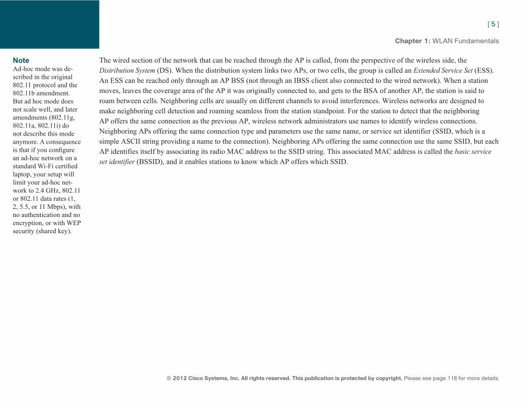
The wired section of the network that can be reached through the AP is called, from the perspective of the wireless side, the Distribution System (DS). When the distribution system links two APs, or two cells, the group is called an Extended Service Set (ESS). An ESS can be reached only through an AP BSS (not through an IBSS client also connected to the wired network). When a station moves, leaves the coverage area of the AP it was originally connected to, and gets to the BSA of another AP, the station is said to roam between cells. Neighboring cells are usually on different channels to avoid interferences. Wireless networks are designed to make neighboring cell detection and roaming seamless from the station standpoint. For the station to detect that the neighboring AP offers the same connection as the previous AP, wireless network administrators use names to identify wireless connections. Neighboring APs offering the same connection type and parameters use the same name, or service set identifier (SSID, which is a simple ASCII string providing a name to the connection). Neighboring APs offering the same connection use the same SSID, but each AP identifies itself by associating its radio MAC address to the SSID string. This associated MAC address is called the basic service set identifier (BSSID), and it enables stations to know which AP offers which SSID.
Note Ad-hoc mode was de-scribed in the original 802.11 protocol and the 802.11b amendment. But ad hoc mode does not scale well, and later amendments (802.11g, 802.11a, 802.11i) do not describe this mode anymore. A consequence is that if you configure an ad-hoc network on a standard Wi-Fi certified laptop, your setup will limit your ad-hoc net-work to 2.4 GHz, 802.11 or 802.11 data rates (1, 2, 5.5, or 11 Mbps), with no authentication and no encryption, or with WEP security (shared key).
ptg7913109
[ 6 ]
© 2012 Cisco Systems, Inc. All rights reserved. This publication is protected by copyright. Please see page 118 for more details.
Chapter 1: WLAN Fundamentals
Infrastructure NetworkInternet
ESS
DS BSABSAChannel 6Channel 1
Roaming
Access Point
BSSID
Wireless ClientsWireless Clients
SSID
Ad-hoc Network
Access Point
WorkgroupBridge
Hub
Repeater
I do “data1”, 00:32:64:bb:01:35I do “data2”, 00:32:64:bb:01:36
MBSSIDI do “data1”, 00:0c:6e:3c:18:11I do “voice1”, 00:0c:6e:3c:18:12
Do you doSSID “data1”?
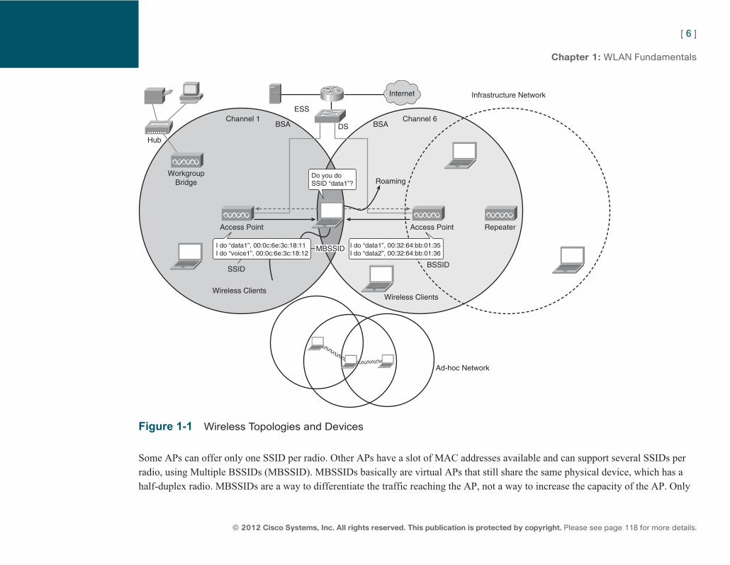
Figure 1-1 Wireless Topologies and Devices
Some APs can offer only one SSID per radio. Other APs have a slot of MAC addresses available and can support several SSIDs per radio, using Multiple BSSIDs (MBSSID). MBSSIDs basically are virtual APs that still share the same physical device, which has a half-duplex radio. MBSSIDs are a way to differentiate the traffic reaching the AP, not a way to increase the capacity of the AP. Only
ptg7913109
[ 7 ]
© 2012 Cisco Systems, Inc. All rights reserved. This publication is protected by copyright. Please see page 118 for more details.
Chapter 1: WLAN Fundamentals
one device can communicate at a time with an AP radio. MBSSID still enables you to create several SSIDs on the same AP radio, each SSID with a different name and individual authentication and encryption mechanisms. This way, stations on different SSIDs share the same RF space but are isolated from each other by different authentication and encryption mechanisms.
In a Cisco controller–based solution, APs attach to controllers. When the AP receives a client data frame, it decrypts any wireless encryption (WEP, TKIP, or AES-CCMP), then encapsulates the 802.11 frame into a CAPWAP packet and forwards this packet to the controller. To achieve the same isolation as on the wireless space, the controller can map each SSID to a different VLAN before releasing the forwarded traffic to the wired side of the network.
Specialized Devices Wireless networks also contain devices offering specific functions. These devices are often access points with a specific firmware used to solve specific connection issues.
APs can be configured to repeat the signal of another access point. This mode is called repeater , and is useful when you want to provide wireless coverage in areas that are too far to allow an Ethernet connection (Ethernet cable length should not exceed 100m, or 328 feet). Repeaters extend the range of the cell and usually reduce the throughput (because the repeater must repeat each client signal to the AP). Some repeaters have two radios (one for the clients, the other to repeat the signal to the main AP) and are called full-duplex repeaters . They are in fact “dual radio half-duplex.”
Workgroup bridges (WGB) are APs used to connect one or several non-wireless devices to the wireless network. The WGB acts as a sort of shared wireless NIC. For the wireless infrastructure, the WGB can be seen as a normal wireless client (this is called the universal workgroup bridge mode, and only one wired client can use the WGB in this mode) or as a special client (simply called workgroup bridge, which is a Cisco proprietary mode allowing several wired client connections). Cisco APs are needed to support Cisco mode WGBs.
APs can also be used to connect entire LANs; for example, two buildings over a campus. In this special configuration, the AP simply transmits the traffic coming from its wired port to another AP over a radio link, and vice versa. The APs must be configured to accept this type of traffic, and are said to be in bridge mode. Bridges can sometimes also accept wireless clients.
ptg7913109
[ 8 ]
© 2012 Cisco Systems, Inc. All rights reserved. This publication is protected by copyright. Please see page 118 for more details.
Chapter 1: WLAN Fundamentals
In larger deployments, multiple APs communicate over their radios. Some APs do not even connect directly to the wired network, and transmit wireless client traffic to other APs. In this configuration, a specific protocol is used for each AP to determine its possible paths to the wired network. This type of deployment is called a mesh network . Paths through the mesh network can change in response to traffic loads, radio conditions, or traffic prioritization.
RF Principles Wireless networks use radio waves to send information. You must know the basic principles of radio wave propagation to understand wireless networks.
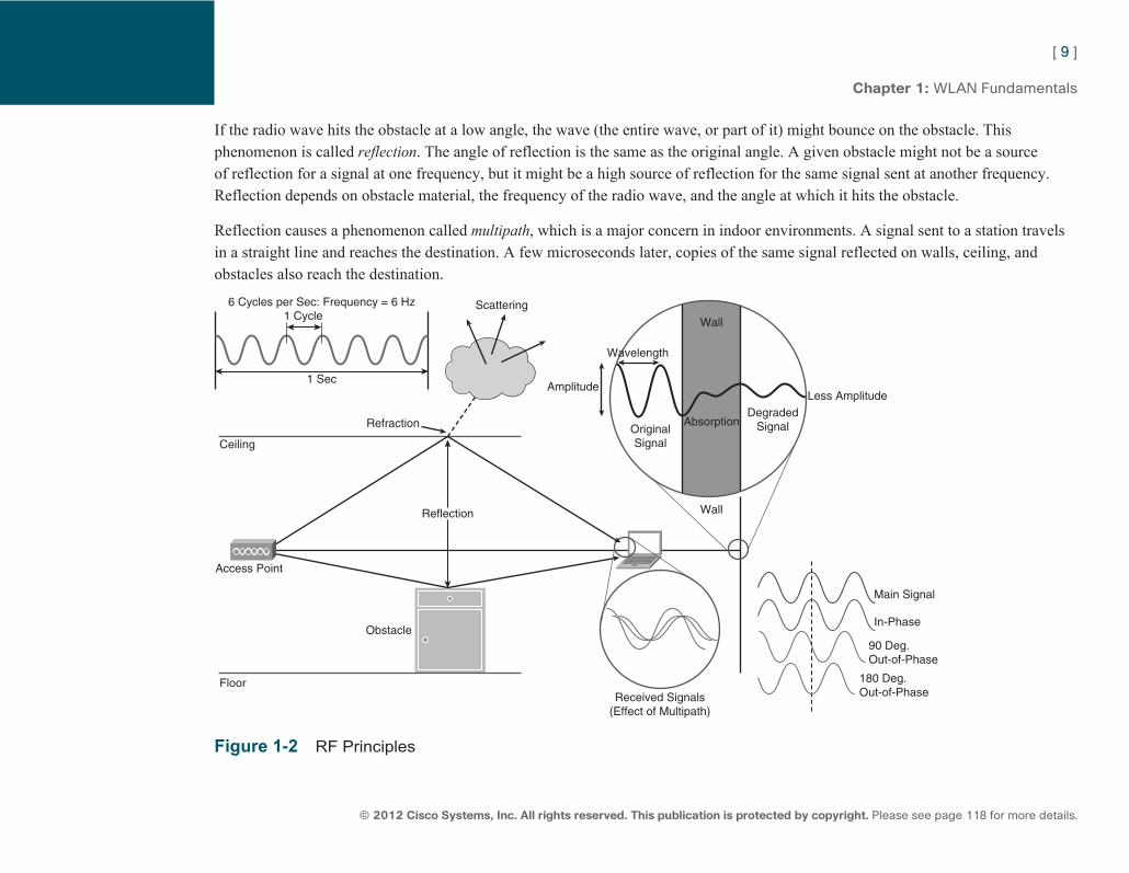
A radio wave is an electric and a magnetic field used to transport information. Radio waves typically use frequencies that the human body cannot detect. Different waves have different sizes that are expressed in meters. Another unit of measurement, hertz (Hz), expresses how often a wave occurs, or repeats, per second. A wave that occurs each second is said to have a frequency of 1 Hz. A wave that occurs one billion times a second has a frequency of a gigahertz (GHz). Lower-frequency signals are less affected by the air than high-frequency signals and travel farther. Wireless networks use the 2.4-GHz band and the 5-GHz band. The 5-GHz band has slightly less coverage than the 2.4-GHz band.
Radio waves repeat their pattern over time (at a given point in space), but also over space. The physical distance from one point of the cycle to the same point in the next cycle is called a wavelength , which is usually represented by the Greek symbol λ (lambda). The wavelength is the physical distance covered by the wave in one cycle.
Another important parameter of the wave is its strength, or amplitude, usually represented by the Greek symbol γ (gamma). In a graphical representation, it is seen as the distance between the higher and lower crest of the cycle.
When a radio wave hits an obstacle, part of the energy of the wave is absorbed by the obstacle material. This phenomenon reduces the amplitude of the wave. If some energy is left, a weaker wave (of lower amplitude but the same frequency and wavelength) will continue on the other side of the obstacle.
ptg7913109
[ 9 ]
© 2012 Cisco Systems, Inc. All rights reserved. This publication is protected by copyright. Please see page 118 for more details.
Chapter 1: WLAN Fundamentals
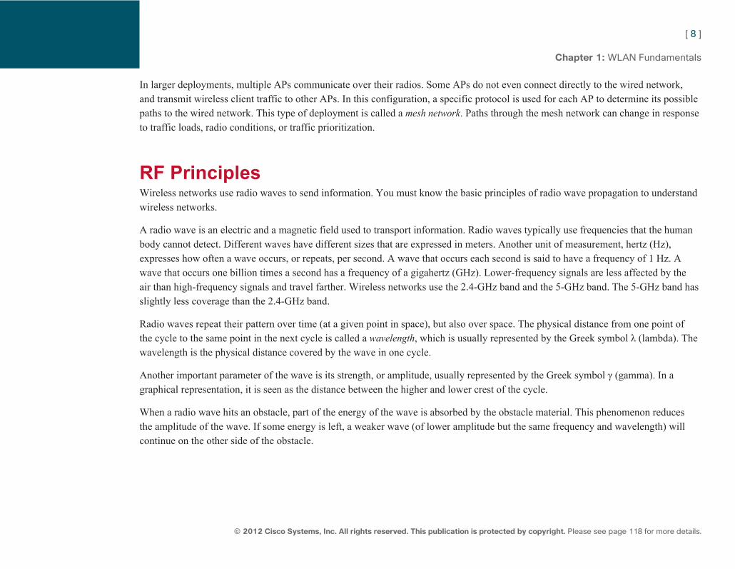
If the radio wave hits the obstacle at a low angle, the wave (the entire wave, or part of it) might bounce on the obstacle. This phenomenon is called reflection . The angle of reflection is the same as the original angle. A given obstacle might not be a source of reflection for a signal at one frequency, but it might be a high source of reflection for the same signal sent at another frequency. Reflection depends on obstacle material, the frequency of the radio wave, and the angle at which it hits the obstacle.
Reflection causes a phenomenon called multipath , which is a major concern in indoor environments. A signal sent to a station travels in a straight line and reaches the destination. A few microseconds later, copies of the same signal reflected on walls, ceiling, and obstacles also reach the destination.
Wall
Wall
Absorption
Main Signal
In-Phase
90 Deg.Out-of-Phase
180 Deg.Out-of-PhaseReceived Signals
(Effect of Multipath)
OriginalSignal
DegradedSignal
Less AmplitudeAmplitude
Scattering6 Cycles per Sec: Frequency = 6 Hz
1 Sec
Access Point
Obstacle
Refraction
Ceiling
Floor
Wavelength
Reflection
1 Cycle
Figure 1-2 RF Principles

ptg7913109
[ 10 ]
© 2012 Cisco Systems, Inc. All rights reserved. This publication is protected by copyright. Please see page 118 for more details.
Chapter 1: WLAN Fundamentals
All these copies can have a destructive effect if they are out of phase. If a signal is received twice at exactly the same time, the secondary wave adds its power to the primary wave, so the receiver gets twice the positive energy (positive crest) at the same instant, then twice the negative energy (negative crest) at the same instant. The result is that both waves add up to twice the amplitude (energy) of a single wave, and both signals are said to be in phase (both signals are said to have an angle of 0 degrees). This rare condition is called upfade . If the second signal negative energy (negative crest) reaches the receiver just when the first signal positive energy (positive crest) also reaches the receiver, both signals can cancel each other, resulting in no signal at all (this is the principle used in noise cancellation headsets). The signals are said to have a 180-degree angle. In most wireless networks, more than two signals are reaching the receiver, and their respective angles are usually between 0 and 180. Because reflection occurs at various points in space, a receiver can be badly affected by reflections at a given position, and not affected at all a few inches away.
To fight against multipath effects, many wireless systems have two antennas linked to the same radio circuit. This is called diversity .
When a frame is detected, the system tests the signal on each antenna and uses the antenna that offers the best signal. The system then responds to the frame from the same antenna that was used to receive it. This antenna decision can be made for each received frame. The system will use one antenna or the other, but never both at the same time. The algorithm used by the system compares the signals heard from both antennas, which implies that the signal must be heard on both antennas for diversity to work. Both antennas should be in the same physical area, and both antennas should be of the same type (so that their signal can be compared).
Reflection also occurs in the air itself, bouncing on dust or micro drops of water (humidity). These multiple reflections are described as scattering . A scattered signal is weaker (because part of it was reflected in other directions along the path) and more diffuse (because many of these micro reflections might hit the receiver). The effect of scattering also depends on the radio wave frequency.
Another phenomenon, less common in indoor wireless networks, is refraction . Refraction occurs when a wave changes direction. This change in direction usually happens when a wave passes from one medium to another (from air to water, for example).
Even without obstacles, a radio wave gets weaker as it moves away from the emitting source because the energy of the wave spreads (in a cone shape for directional wave, or in a circle similar to ripples in water for omnidirectional antennas). The same amount of energy must cover a larger space, which reduces the amount of energy available at any given point. This signal attenuation related to distance from the emitter is called free path loss .
Note Do not confuse diver-sity and MIMO used in 802.11n APs. With diversity, both antennas are linked to a single ra-dio circuit. With MIMO, there are several antennas and several radio circuits.
ptg7913109
[ 11 ]
© 2012 Cisco Systems, Inc. All rights reserved. This publication is protected by copyright. Please see page 118 for more details.
Chapter 1: WLAN Fundamentals
Free path loss is taken into account to determine how much energy must be sent from an emitter to reach a receiver in good conditions. This calculation is called the link budget . The RF signal must be able to travel directly from the sender to the receiver for the transmission to occur. RF engineers refer to this direct connection as RF line of sight . It is different from visual line of sight (there might be a light obstacle on the path preventing visual line of sight, but there might be enough energy in the signal to directly reach the destination through the obstacle, allowing for RF line of sight).
For long-range radio links, the earth curvature prevents RF line of sight as soon as the range exceeds 7 to 10 miles. You then need to raise the antennas to maintain the line of sight.
A successful signal actually requires more than simple line of sight. Dense obstacles close to the line of sight can take too much of the wave energy (or reflect it, causing multipath issues) for the receiver to correctly interpret the received signal. The nineteenth-century physicist Augustin-Jean Fresnel calculated zones around the line of sight where reflected signals would destruct (odd zones) or reinforce (even zones) the main signal. Theoretically, an infinite number of zones exist, but the area of main concern is the first zone. Some obstruction might be acceptable, but at least 60 percent of this first zone should be free from any obstacle to allow for a signal of acceptable quality.
Because the RF wave might have been affected by obstacles in its path, it is important to determine how much signal is received by the other endpoint. The value that indicates the amount of power received is called Received Signal Strength Indicator (RSSI). It is a negative value measured in dBm. A higher value (closer to 0) is better and shows a louder signal. Calculating the RSSI is difficult because the receiver does not know how much power was originally sent. Therefore, the RSSI is just a value determining the capability of the receiving card to convert the received signal into data, and there is no absolute RSSI scale. Two cards from different vendors at the same point in space can indicate different RSSIs for the same received signal.
The capability for a wireless card to convert the received signal into data is also affected by the other radio waves hitting the receiver along with the main signal. This unuseful signal received at the same frequency as the main signal is called noise , and it is a negative value measured in decibels (dB). A lower noise value (–100 is lower than –10) is a sign of a quieter (less noisy) and better environment. The difference in strength between the main signal and the background noise is called Signal to Noise Ratio (SNR). To receive a signal in good condition, a station needs a specific minimum RSSI value but also a specific minimum SNR. Failure to meet one or the other prevents the station from understanding the signal.
ptg7913109
[ 12 ]
© 2012 Cisco Systems, Inc. All rights reserved. This publication is protected by copyright. Please see page 118 for more details.
Chapter 1: WLAN Fundamentals
RF Mathematics
dB and dBm RSSI is expressed in dBm because wireless signals are electric fields. Inside a station or an AP, a transmitter generates an electric current that is forwarded to the antenna and radiated. The strength of this electric current is expressed in watts (in fact, in thousandths of watts, or milliwatts). Comparing two signals expressed in milliwatts can be done directly (signal X is Y milliwatts stronger than signal Z) or by using the decibel scale. The decibel scale was invented by Bell Laboratories to compare sound signal strength in the early days of analog telephony. This scale was then generalized to many other fields, because it simply compares powers on a logarithm scale. The unit used by the items to compare is simply added to the symbol dB to express that you are comparing relative powers (dBm to compare the relative power [dB] of two signals expressed in milliwatts, dBHz to compare Hertz, and so on).
The dB scale is widely used in wireless networks because it enables you to compare relative powers instead of absolute powers. For example, if signal A is 1 mW and signal B is 4 mW, a direct comparison tells you that B is 3 mW stronger than A. If signal C is 25 mW and signal D is 100 mW, a direct comparison tells you that D is 75 mW stronger than C. When comparing all these signals together, a direct comparison might lead you to think that there is a greater difference between C and D (75 mW) than between A and B (3 mW). This is true but can be misleading. The dB scale tells you that B is four times as powerful as A and D is also four times as powerful as C. C is a lot larger than A, but the relative difference between D and C and between B and A is the same (D and B are four times as powerful as C and A, respectively). This makes sense when associated with other rules. For example, for wireless networks, a signal four times more powerful will double the useful distance at which that signal can be received. The direct scale tells you that C is larger than A, but the dB scale enables you to easily determine that the distance doubles between A and B, and the distance also doubles between C and D.
The decibel scale is logarithmic, which is a little difficult to calculate mentally. To simplify your task, remember three simple values:
■ 0 dB: A measurement of 0 dB is the reference value (signal A is 0 dBm stronger or weaker than another 1 mW signal).
■ 0 dB: When the power is 10 dB, the source being examined is ten times more powerful than the reference value. This also works in reverse: If the power is –10 dB, the source being examined is ten times less powerful than the reference value.
■ 3 dB: If the power is 3 dB, the source being examined is twice as powerful as the reference value. With the same logic, if the examined object is half as powerful as the reference value, it will be written –3 dB.
ptg7913109
[ 13 ]
© 2012 Cisco Systems, Inc. All rights reserved. This publication is protected by copyright. Please see page 118 for more details.
Chapter 1: WLAN Fundamentals
Take some time to study those values. dB values get added or subtracted when powers are multiplied. This means for the previous examples that B is 6 dBm stronger than A (1 mW × 2 = 2 mW. 2 mW × 2 = 4 mW, you added 3 dB [multiplied by 2] twice), but D is 20 dBm stronger than A (1 mW × 10 = 10 mW. 10 mW × 10 = 100 mW). You added 10 dB (multiplied by 10) twice.
Practice is needed to master these conversions. Always start with the 10 dBs, and then add the 3 dBs. A few example comparisons may help:
1 mW <-> 1 mW: 0 dB 4000 mW (or 4 W) <-> 20 mW: 23 dB (20 x10 = 200. 200 x 10 = 2000. 2000 x 2 = 4000) 0.5 mW <-> 20 mW: -16 dB (20/10 = 2. 2/2 = 1. 1/2 = 0.5)
RF engineers often use the dBm scale to compare a power in milliwatt to a 1 mW reference power. You will often see the power of an AP expressed in dBm. For example, an AP with a 20 dBm power level is an AP sending a 100 mW current to the antenna (1 × 10 = 10. 10 × 10 = 100). You need to master these computations for the CCNA Wireless exam.
Some comparisons cannot be done easily with these three simple rules (for example, 10 mW <-> 50 mW). You can easily find dB calculators and tables online (but you do not need them for the CCNA Wireless exam).
dBi and dBd The dB scale is also used to compare the relative power (called gain ) of antennas. The reference is not 1 mW anymore, because there is no real electricity transmitted through the air, and also because the purpose is not to measure relative electricity power values but to compare the capability of an antenna to focus an RF signal. To allow for simpler comparison, a theoretical reference antenna was imagined to be used as a reference point against which all antennas would be compared. This imaginary antenna is called the isotropic antenna and is imagined as an antenna that would be one point wide and would radiate its signal perfectly equally in all directions. Such an antenna does not exist, of course (no antenna can be “one point” small, and the antenna hardware would never allow an antenna to radiate perfectly the same way in all directions), but this does not matter. This imaginary antenna provides a point of reference, and you will find antenna gains (or power) expressed in dBi (for dB relative to the theoretical Isotropic antenna). You can then compare antennas to each other. With the dB scale, you know that a 6 dBi antenna that has twice as much gain as a 3 dBi antenna and four times as much gain as the theoretical isotropic antenna.
ptg7913109
[ 14 ]
© 2012 Cisco Systems, Inc. All rights reserved. This publication is protected by copyright. Please see page 118 for more details.
Chapter 1: WLAN Fundamentals
DBi is the most common scale for antenna gains, but some wireless professionals prefer to use an existing antenna as the reference. The antenna chosen is the simplest possible antenna, called a dipole antenna . This comparison is expressed in dBd. This scale is less common, but converting back and forth is easy. A basic dipole antenna gain is 2.14 dBi. It is also 0 dBd (as the basic dipole antenna gain is exactly the dipole antenna gain, no more and no less). A 6 dBi antenna can also be said to be a 3.86 dBd antenna (6 – 2.14). In other words:
■ dBi = dBd + 2.14
■ dBd = dBi – 2.14
Antenna Principles
Polarization Different antennas have different ways of focusing the energy received from the transmitter. All of them emit an electric field, which is the radio wave. A magnetic field is associated to this electric field. This magnetic field is said to be on the left of the wave, which is a convention to say that when the wave moves upward, there is a positive magnetic field on the left side of the wave (then on the right side when the wave moves downward). This radio wave can go up and down, and the antenna is then said to be vertically polarized. The antenna can also be designed to let the wave travel with a left-right movement (the antenna is the horizontally polarized, and the magnetic field is above then below). More complex patterns are possible (for example, circular polarization, where the wave circles as it moves forward). Most wireless networks use vertical polarization. The polarization does not actually matter (the relative position of the earth to the wave does not change the wave), but emitter and receiver should use the same polarization. This is not critical indoors, where multipath will make sure that all sorts of polarized signals will reach the receiver, but it is very important outdoors, especially for long-range links. A polarization mismatch might make the received signal up to 20 dB weaker than it would be if it were polarized properly.
ptg7913109
[ 15 ]
© 2012 Cisco Systems, Inc. All rights reserved. This publication is protected by copyright. Please see page 118 for more details.
Chapter 1: WLAN Fundamentals
Radiation Patterns Each antenna has a gain value, but you should not think that the antenna actively amplifies the signal received from the transmitter. The gain compares the signal sent by the antenna to the same signal if it were sent by the isotropic antenna. The isotropic antenna radiates all the energy of the signal to a perfect sphere. If your antenna radiates the energy in only one direction, you receive more energy in that direction than you would receive at the same point in space if the antenna was isotropic. The global amount of energy is the same, it is just more focused. The gain simply measures how much more energy you receive in that direction.
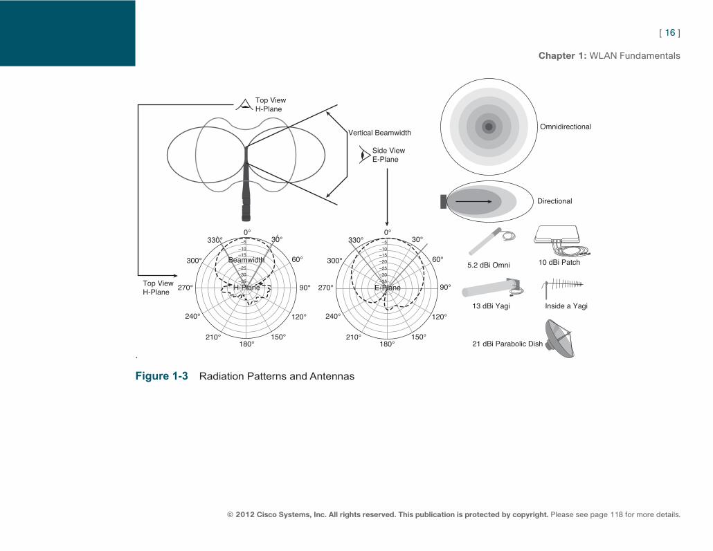
Antenna vendors use radiation pattern charts to describe the signal sent by an antenna. This chart provides a view from above the antenna (the horizontal plane [H-plane], or azimuth chart) and a view from the side (the elevation plane [E-plane], or elevation chart). The H-plane shows how the signal spreads ahead, behind, on the right, and on the left, but not up and down, and provides a flat or horizontal view. The E-plane shows how the signal spreads ahead, behind, on the top, and the bottom, but not on the right and left; it provides a top-down view of the signal shape.
Vendors then take a point in space where the strongest signal is received and use this point as a reference. It is represented as the outer circle in Figure 1-3 . Then a line represents how much less energy you would receive when walking in a circle around the antenna. This is often confusing. You must move in a circle while staying at the same distance from the antenna. The dashed line shows how much less energy you receive as you move away from the point of the main focus of the radiated energy. In Figure 1-3 , you receive 18 dB less energy if you stand at a 60 degree position on the right of the antenna than you would receive if you were in front (position 0) of the antenna, still at the same distance
ptg7913109
[ 16 ]
© 2012 Cisco Systems, Inc. All rights reserved. This publication is protected by copyright. Please see page 118 for more details.
Chapter 1: WLAN Fundamentals
.
Omnidirectional
Directional
5.2 dBi Omni 10 dBi Patch
13 dBi Yagi
21 dBi Parabolic Dish
Inside a Yagi
Top ViewH-Plane
Top ViewH-Plane
Side ViewE-Plane
Vertical Beamwidth
–35
–25–30
–20–15–10
–5
–35
–25–30
–15–10
–5
0°30°
60°
90°
120°
150°180°
210°
240°
270°
300°
0°30°
60°
90°
120°
150°180°
210°
240°
270°
300°
330° 330°
H-Plane
Beamwidth
E-Plane
Figure 1-3 Radiation Patterns and Antennas
ptg7913109
[ 17 ]
© 2012 Cisco Systems, Inc. All rights reserved. This publication is protected by copyright. Please see page 118 for more details.
Chapter 1: WLAN Fundamentals
To determine the area where most of the energy is being radiated (called the beamwidth ), vendors take the points where the signal degrades by 3 dB (half the power). In the figure, this point is situated at about 30 degrees on each side of the main direction of radiation, and the antenna beamwidth is said to be 60 degrees (30 degrees on each side).
Antenna Types There are two main types of antennas: omnidirectional and directional. Omnidirectional antennas radiate equally in all directions in the H-plane. They usually do not radiate equally in all directions in the E-plane. Their radiation pattern is often said to look more like a donut than a pure sphere. This shape is common for many indoor omnidirectional antennas, the difference being the thickness of the donut. The basic dipole antenna (also called a rubber duck antenna) has a 2.14 dBi gain and its radiation pattern looks like a thick donut. A 5.2 dBi omnidirectional Cisco AIR-ANT1728 antenna radiation pattern looks like a flatter donut, offering more gain in the H-plane but less gain in the E-plane. You can even find 12 dBi omnidirectional antennas; their radiation patterns look like a very flat donut. The antenna you choose depends on the type of area you need to cover.
A special type of omnidirectional antenna, the dual-omnidirectional antenna, is made of two patch directional antennas back to back. It is used to provide coverage to a hall, using a pillar in the middle to fix the antennas. Although both antennas are a directional patch, the result is still called omnidirectional.
A patch antenna is a type of directional antenna. A directional antenna is designed to cover one specific direction in both the E-plane and the H-plane. As the beamwidth in both planes narrows, the range and the gain increase. The patch antenna is a common directional antenna, with an 8 to 10 dBi gain depending on models. It is commonly used on walls to cover a hall or a large meeting room.
The Yagi (or Yagi-Ude, from the names of its inventors) looks like a tube in which a comb-like antenna (looking like an analog TV antenna) is inserted. Each “tooth” of the comb amplifies the signal of the other teeth. Most Yagis have this small radiated field at the back, which is called the “butterfly effect.” The manufacturing process also creates side lobes, thin coverage areas on the side of the main field. A Yagi commonly has a 13 dBi gain and is used, for example, to cover long hallways.
At the end of the spectrum, the parabolic dish has a very narrow beam. It looks like a satellite parabolic dish and is used for outdoor long-range point-to-point links. Depending on models, the gain can range from 21 dBi to 28 dBi.
ptg7913109
[ 18 ]
© 2012 Cisco Systems, Inc. All rights reserved. This publication is protected by copyright. Please see page 118 for more details.
Chapter 1: WLAN Fundamentals
Antenna Accessories WLANs operate in license-free RF-bands, so you do not have to pay a fee to use any equipment in these bands. The RF is still regulated, which means that each country’s regulation authorities determine how much the signal is (how powerful) and what type of signal you can send in these frequencies. As long as you use an AP and an antenna made by the same manufacturer, you will use a certified system and will be within the limit of the allowed power levels. But if you were to use an AP, which transmitter power is set to be sent to an omnidirectional antenna, and if you were to connect a parabolic dish initially designed for an AP with a weaker transmitter, you might be emitting a signal stronger than the maximum level allowed in your country. To avoid this situation, most countries have regulations requiring that each AP manufacturer use a specific connector to connect its antennas to its APs. You can still find connector adapters for most systems. The regulations exist to prevent unintentional mistakes, not to say that breaking the law is impossible. Cisco APs commonly use a connector called reverse-polarity threaded Neill-Concelman (RP-TNC), and another one called N connector (for outdoor APs). Some other connectors that can be commonly found on other vendors devices are the Subminiature Version A (SMA) and its variants, the reverse-polarity SMA (RP-SMA). Some vendors use the multipoint controller (MC) or the multimedia communication exchange (MMCX) connector. There are quite a few others, but these are the main families.
If the antenna is not connected directly to the AP, it can be linked to the AP using a cable. The cable absorbs part of the energy transmitted, which results in a loss in the signal power (amplitude) at the end of the cable. All cable vendors specify the loss value (in dB per foot or per meter of cable). In some cases, you might want to use a cable with high loss; for example, when connecting a powerful transmitter to a high gain antenna, so as not to exceed the local allowed maximum values.
If the signal received from the transmitter at the antenna is too weak, you can increase it with an amplifier (an electronic device connected to a power source that increases the signal amplitude). On the other hand, if the signal received is too strong, you can reduce it by inserting an attenuator (a simple passive device that is graded to absorb a specific number of dBs in the signal).
Another accessory you might find in outdoor antenna systems is a lightning arrestor. This small device is inserted between the antenna and the AP to dissipate surrounding static electricity, acting as a simple circuit breaker. It does not protect the system from a direct lightning strike. There is no possible protection for the AP from such powerful energy—the AP will probably be destroyed, even with a lightning arrestor. It is common to position a medium between the AP and the rest of the network that will not conduct electricity—for example, a fiber section of about a yard (or a meter) long without any loops. This prevents the entire network from being destroyed if the AP is struck by a lightning bolt.
ptg7913109
[ 19 ]
© 2012 Cisco Systems, Inc. All rights reserved. This publication is protected by copyright. Please see page 118 for more details.
Chapter 1: WLAN Fundamentals
EIRP With the multiple possible combinations of AP transmitter power level, cables and antenna, you need a way to determine how much energy is actually radiated from the antenna toward the main beam. This measure is called the Effective Isotropic Radiated Power (EIRP). In simple terms, the EIRP, expressed in dBm, is simply the amount of power emitted by the transmitter plus the gain (in dBi) of the antenna (and any amplifier on the path). You also must remove the power lost in cable or attenuators:
EIRP = Tx power (dBm) + antenna gain (dBi) – cable loss (dB)
The EIRP is very important. Most countries allow a maximum Tx power of the transmitter and a final maximum EIRP value. When designing networks with specific antennas, you must know your system EIRP and make sure it complies with local regulations.
Regulatory Bodies Each country has its own set of regulations that determines what type of signal (what shape and power level) can be sent in each part of the global RF spectrum. It is common for several countries to agree and group their rules into one global regulatory domain. In the United States and several other countries in the American continents, the FCC determines what frequencies and transmission power levels may be used. Europe and some other countries (such as Israel and Mexico) follow the specifications of the European Telecommunication Standards Institute (ETSI). In Japan, rules are defined by the Ministry of Communication, and their applications are managed by Telec.
Bands and Channels WLANs can operate in two main bands: the 2.4 GHz band, which spans from 2.4000 GHz to 2.4835 GHz, and the 5 GHz band.
The 2.4 GHz band was declared nonlicensed for any industrial, scientific, and medical (ISM) equipment by the ITU. All countries’ members of the ITU agree to this classification. This is how you can use equipment operating in this band without having to pay a license. This band is divided into channels. One difficulty is that those channels are 5 MHz apart. Channel 1 is centered on the 2.412 GHz frequency, channel 2 on 2.417 GHz, and so on. But WLANs use 20 to 22 MHz–wide channels. This makes channel 1 and 2 overlap. They cannot be used in the same physical location. If you want to use several channels in the same physical space, they must
ptg7913109
[ 20 ]
© 2012 Cisco Systems, Inc. All rights reserved. This publication is protected by copyright. Please see page 118 for more details.
Chapter 1: WLAN Fundamentals
be nonoverlapping. Channel 1 spans from 2.401 GHz to 2.423 GHz. Channel 6 is centered on 2.437 GHz and spans from 2.426 GHz to 2.448 GHz. Channels 1 and 6 are nonoverlapping and can be used concurrently at the same location. Channel 5 overlaps a little bit with channel 1. Channel 1 and 6 are said to be adjacent (because channel 6 is the nonoverlapping channel closest to 1). Channels 1, 6, and 11 are nonoverlapping. In the 2.4 GHz band, there are only three nonoverlapping channels.
Notice that some European countries use channels 1, 5, 9, and 13 for data and accept the price of the slight overlap to gain one more channel.
The 5 GHz band is actually divided into four sub bands. There is no worldwide agreement on this band; some countries allow all channels, some countries allow some channels, and some countries ban WLAN from using the 5 GHz spectrum.
■ The first band (called band 1, or unlicensed national information infrastructure 1 [UNII-1] in the United States) spans from 5.15 to 5.25 GHz. Four channels (36, 40, 44, and 48) can be used; channels are 20 MHz apart.
■ Band 2 (UNII-2) spans from 5.25 to 5.35 GHz and also allows for four 20 MHz apart channels (52, 56, 60, and 64).
■ Band 3 (UNII-2 extended) spans from 5.47 to 5.725 GHz and contains eleven 20 MHz-apart channels (100, 104, and so on, up to 140).
■ Band 4 (UNII-3) spans from 5.725 GHz to 5.825 GHz and contains four 20 MHz channels (149, 153, 157, and 161). This last band is ISM (the other bands are not ISM).
Channel 165, centered on 5.825 GHz, spans outside band 4 (UNII-3) but is still in the ISM segment. Some systems add this channel to the list of possible channels in the last band. Each country has different rules as to how these bands can be used. You do not need to know all the rules for all domains to pass the exam, but you need to know some basic principles for the two main domains, FCC and ETSI.
FCC Rules In 1994, the FCC was the first regulatory body to decide that any removable antenna had to use a unique, nonstandard connector.
ptg7913109
[ 21 ]
© 2012 Cisco Systems, Inc. All rights reserved. This publication is protected by copyright. Please see page 118 for more details.
Chapter 1: WLAN Fundamentals
The FCC also has a precise set of rules for transmissions in the unlicensed bands. A vendor must have its equipment approved by the FCC before being allowed to sell it. As a wireless user, you also must respect power limitations for your equipment EIRP. These rules are different depending on the frequency range and the usage:
■ For point-to-multipoint links in the 2.4 GHz unlicensed band, the maximum EIRP is 36 dBm, with 30 dBm maximum at the transmitter level (supposing a 6 dBi antenna). A 1:1 rule applies: Each dBm removed from the transmitter can be added to the antenna gain. This way, you could use, for example, a 20 dBm transmitter with a 16 dBi antenna.
■ For point-to-point links in the 2.4 GHz unlicensed band, the maximum is still 30 dBm at the transmitter level (supposing a 6 dBi antenna). This time, a 3:1 rule applies and the EIRP can exceed 36 dBm. Each dBm removed from the transmitter can translate as 3 dB added to the antenna gain. This way, you could, for example, use a 25 dBm transmitter (removing 5 dBm from the transmitter) and a 21 dBi antenna (6+3×5), resulting in a 51 dBm EIRP.
The FCC allows channels 1 to 11, indoor and outdoor.
In the 5 GHz band, the rules depend on the sub band. All four bands are allowed for indoor WLANs, but UNII-1 is not allowed for outdoor WLANs. In the UNII-1 band, output power should not exceed 50 mW (17 dBm), with 22 dBm EIRP maximum. In the UNII-2 band, output power should not exceed 250 mW (24 dBm), with 29 dBm EIRP. In the UNII-2 extended and the UNII-3 bands, output power should not exceed 1 W (30 dBm), with 36 dBm EIRP. All 5 GHz bands use the 1:1 rule.
ETSI Rules The ETSI rules in the 2.4 GHz band are simple. Thirteen channels are allowed, and the power rules are the same for point-to-point and point-to-multipoint networks. The maximum output power at the transmitter is 17 dBm, with a 20 dBm maximum EIRP (supposing a 3 dBi default antenna). The 1:1 rule applies (each dBm removed from the transmitter can be added to the antenna gain).
The rules are a bit more complex in the 5 GHz band. Bands 1 and 2 (UNII-1 and UNII-2) are allowed only for indoor networks. Band 3 (UNII-2e) is allowed for both indoor and outdoor networks. Band 4 (UNII-3) is licensed and cannot be used. The ETSI rules do not refer to the output power, modified with the 1:1 rule, but only to the EIRP (so the output power does not matter, as long as the EIRP is respected). In the first two bands (bands 1 and 2, or UNII-1 and UNII-2), EIRP should not exceed 23 dBm. In band 3 (UNII-2e), EIRP should not exceed 30 dBm.
ptg7913109
[ 22 ]
© 2012 Cisco Systems, Inc. All rights reserved. This publication is protected by copyright. Please see page 118 for more details.
Chapter 1: WLAN Fundamentals
IEEE and the Wi-Fi Alliance The Institute of Electrical and Electronics Engineers (IEEE) is a worldwide professional organization that develops standards in electrical and computer sciences, engineering, and related fields. In February 1980, its communication committee defined several network communication areas, which were divided into working groups (starting with number 802, for February 1980). The eleventh working group in this category, 802.11, was created in 1990 to analyze the applications and environments in which wireless networks are used. This group is open, and comprised of engineers from different wireless data companies working together to build a standard that should be better than any of the proprietary solutions. The group has liaison officers with the main regulatory bodies to evaluate how new protocol improvements would be allowed in each regulatory region. Each time the need for a new improvement emerges, a new task group is created that works on an amendment to the standard. Each amendment bears the standard number and one or two letter codes (for example, 802.11ac, amendment for 1 Gbps throughput in 5 GHz, to be released in 2013).
Each company is then free to implement the entire standard specifications or part of it, or to add additional proprietary features. To ensure compatibility between solutions, the Wi-Fi Alliance was created to test product interoperability and verify their implementation of the standard. The certified product receives a Wi-Fi certified stamp.
Spread Spectrum Technologies
FHSS Using a high power level might be thought as a way to overpower interferences. In indoor environments, this is usually a wrong choice because more power means more multipath. Another way to avoid interference is to change frequency. Interference is often due to narrowband signals. Narrowband means they affect only a specific frequency. If you have the right to send your signal anywhere in the ISM band between 2.4 GHz and 2.835 GHz, a good choice might be to never stay long on the same frequency, and to jump from one frequency to the other within the 2.4–2.835 GHz band. This technique is called frequency hopping spread spectrum (FHSS). The band is divided into many small channels (close to 80 channels in the U.S.). The emitter chooses and informs the receiver about the channel hop sequence (for example, channel 1, then 67, then 32, then 8) and emits its signal while jumping from one channel to the next every 300 to 400 ms. If a source of interference destructs the signal on one channel, only 300 to 400 ms worth of information are lost. This technique is efficient to combat interferences but is not adapted to modern wireless networks for two
ptg7913109
[ 23 ]
© 2012 Cisco Systems, Inc. All rights reserved. This publication is protected by copyright. Please see page 118 for more details.
Chapter 1: WLAN Fundamentals
reasons: It does not scale well (if you have more than 10 senders and receivers, the different hop sequences collide and everyone suffers from the interferences due to the others’ jump sequences), and the quantity of information that can be sent on each channel is limited. This limitation is due to the fact that each channel is 1 MHz wide. This means that if the channel frequency is set to 2.412 GHz, the signal will in fact spread from 2.4115 GHz to 2.4125 GHz. RF calculations show that you can send only 1 Mbps worth of information in such a channel.
FHSS is still described in the original 802.11 protocol, but another technique was preferred and adopted by all 802.11 networks: Direct Sequence Spread Spectrum. Instead of small channels and a jumping sequence, the information is sent over a wider channel. This channel is 22 MHz wide (if the center frequency is 2.412, this channel spans from 2.401 GHz to 2.423 GHz) and does not move (no hopping, which is why the sequence is said to be direct instead of hopping). Then, over this 22 MHz channel, several bits of information are sent in parallel. If a source of interference affects part of the channel, it will prevent only the bits sent in that frequency from reaching the receiver.
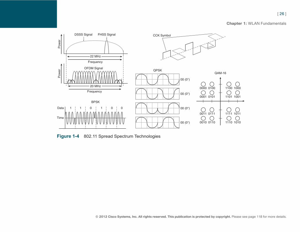
DSSS Encoding To survive this common issue, DSSS uses a code. For every 0 or 1 you want to send, DSSS generates a code representing that 0 or that 1. This code, also called symbol or chip , can be a sequence of up to 11 bits (this is called the Barker 11 code), and these 11 bits are sent in parallel over the 22 MHz channel. You can lose up to nine of these 11 bits due to interferences and still understand whether the code sent was supposed to represent a 0 or a 1.
DSSS Modulations: BPSK and QPSK This technique makes DSSS very resistant to interferences. But how can you represent those 0 and 1s in a RF wave? This representation is called modulation , changing the wave to mean something. A radio wave is a signal that goes up and down, after all. A first technique is to determine a tempo (for example, 1 million symbols per second, which means 1 symbol every microsecond) and simply reverse the direction of the wave when the next symbol is a 1. This technique is called Differential Binary Phase Shift Keying (DBPSK). Simply put, DPSK states the rule: When the next value to send is a zero, do nothing special but continue sending the wave without alteration. When the next value to send is a 1, change direction (if the wave was going up, suddenly go down, and vice versa). This rule is applied to each of the 11 zeros and ones sent in parallel over the 22 MHz channel. The result is a 1 Mbps communication.
ptg7913109
[ 24 ]
© 2012 Cisco Systems, Inc. All rights reserved. This publication is protected by copyright. Please see page 118 for more details.
Chapter 1: WLAN Fundamentals
How can you send more information in the same wave? You could send more symbols per seconds (1 billion for example), but this would be dangerous (with weak signals and multipath, you might not be able to read the signals) and expensive (you need a high-quality circuit to read that many symbols per second). The second option is to keep the same tempo but make each symbol mean more than 1 or 0. This technique was chosen, and is called Differential Quadrature Phase Shift Keying (DQPSK). It is a bit more complex than QPSK. DPSK groups bits by pairs (00, 01, 10, 11) and states the rule that, if the group to transmit is 00, do nothing (carry on sending the wave as it is). If the group to transmit is 01, turn 90 degrees. (If the wave was going up, the signal should carry on from the top of the wave, if the wave was going down, the signal should carry on from the bottom of the wave, if the wave was on the high crest, the signal should carry on going down from the zero line, and so on.) If the group to transmit is 10, turn 270 degrees. (If the signal was going up, the signal should carry on from the bottom. If the wave was going down, the signal should carry on from the top, and so on.) If the group to transmit is 11, turn 180 degrees, which is shifting phase just like DBPSK. If the wave is going up, go down; if it is going down, go up, and so on.
This technique doubles the number of bits transmitted in each wave direction change, allowing for 2 Mbps data transmission.
CCK How to go faster? By using another technique, called Complementary Code Keying (CCK) and going away from Barker 11. Each group of 4 bits is encoded into a 6-bit symbol (instead of 11 bits with Barker 11). There are 64 (2 to the power of 6) different symbols, each one representing a unique 6-bit chip. To each 6-bit chip, two other bits are added (to represent the orientation of the beginning of the symbol and help if part of the symbol is not received), resulting in an 8-bit-long code symbol. The wave is sent over 22 MHz at a speed of 1.375 million code symbols per second, each representing 4 bits, resulting in a speed of (1.375 × 4) 5.5 Mbps throughput. This result is far better than Barker + DQPSK. In a later version of CCK, the initial 2 bits are used to represent two different symbols instead of just the orientation of the symbol, thus doubling the rate to 11 Mbps.
ptg7913109
[ 25 ]
© 2012 Cisco Systems, Inc. All rights reserved. This publication is protected by copyright. Please see page 118 for more details.
Chapter 1: WLAN Fundamentals
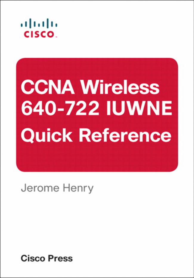
OFDM 11 Mbps was still not enough in a world where LAN speeds were commonly reaching 100 Mbps. Another modulation technique, already in use in some other RF transmission systems, was brought to WLANs: Orthogonal Frequency-Division Multiplexing (OFDM). Instead of sending one large 22-MHz wave, OFDM divides a 20-MHz channel (yes, 20 MHz, slightly narrower than 22 MHz DSSS) into 52 subchannels, called subcarriers or tones, 312.5 kHz apart. Forty-eight of them are used to carry data, while the other four are used to control the communication. To these 52 subcarriers, 12 others are added to be used as guards on the side (to distinguish one main carrier from the other next to it) and in the middle to mark the center of the channel. Then, each subcarrier uses BPSK or QPSK. Because there are many tones, each of them does not need to be very fast; it is their number that creates the speed. This technique allows for up to 18 Mbps of data throughput.
Going faster requires again moving away from BPSK/QPSK and using a technique called Quadrature Amplitude Modulation (QAM). QAM changes the amplitude and the wave direction to represent the next group of bits. To four wave direction changes present with QPSK, QAM adds four amplitude levels (null, low, average, and high). Four amplitudes times four directions create 16 possibilities (16 symbols), thus the name of the first variant, 16-QAM. This variant allows 4 bits to be coded by symbol and 500 kbps per carrier. To improve the resistance of this system, each symbol is repeated twice (this is called 1/2, because only 1/2 the symbols are new), and allows for 24 Mbps total throughput. The speed can be increased to 36 Mbps by only repeating 1/4 of the symbols (this is called 3/4). To increase the speed even more, OFDM can use 64-QAM. The behavior is the same, except that there are 64 symbols instead of 16, and 8 bits are coded in each symbol. Using 64-QAM allows 1 Mbps per carrier, or 48 Mbps. At that speed, 2/3 of the bits are new information bits and 1/3 of the bits are redundant. By increasing the ratio to 3/4 new information and 1/4 redundant bits, the speed can increase to 54 Mbps (1.125 Mbps per carrier).
ptg7913109
[ 26 ]
© 2012 Cisco Systems, Inc. All rights reserved. This publication is protected by copyright. Please see page 118 for more details.
Chapter 1: WLAN Fundamentals
00 (0°)
QPSK
Time
Data
Pow
er
BPSK
Frequency
OFDM Signal
22 MHz
DSSS Signal FHSS Signal
1 1 0 1 0 0
QAM-16
CCK Symbol
00 (0°)
0000
00 (0°)
00 (0°)
0100
0001 0101
1100 1000
1101 1001
0011 0111
0010 0110
1111 1011
1110 1010
Pow
er
Frequency
20 MHz
Figure 1-4 802.11 Spread Spectrum Technologies
ptg7913109
[ 27 ]
© 2012 Cisco Systems, Inc. All rights reserved. This publication is protected by copyright. Please see page 118 for more details.
Chapter 1: WLAN Fundamentals
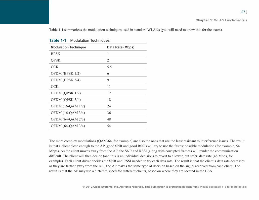
Table 1-1 summarizes the modulation techniques used in standard WLANs (you will need to know this for the exam).
Table 1-1 Modulation Techniques
Modulation Technique Data Rate (Mbps)
BPSK 1
QPSK 2
CCK 5.5
OFDM (BPSK 1/2) 6
OFDM (BPSK 3/4) 9
CCK 11
OFDM (QPSK 1/2) 12
OFDM (QPSK 3/4) 18
OFDM (16-QAM 1/2) 24
OFDM (16-QAM 3/4) 36
OFDM (64-QAM 2/3) 48
OFDM (64-QAM 3/4) 54
The more complex modulations (QAM-64, for example) are also the ones that are the least resistant to interference issues. The result is that a client close enough to the AP (good SNR and good RSSI) will try to use the fastest possible modulation (for example, 54 Mbps). As the client moves away from the AP, the SNR and RSSI (along with corrupted frames) will render the communication difficult. The client will then decide (and this is an individual decision) to revert to a lower, but safer, data rate (48 Mbps, for example). Each client driver decides the SNR and RSSI needed to try each data rate. The result is that the client’s data rate decreases as they are farther away from the AP. The AP makes the same type of decision based on the signal received from each client. The result is that the AP may use a different speed for different clients, based on where they are located in the BSA.
ptg7913109
[ 28 ]
© 2012 Cisco Systems, Inc. All rights reserved. This publication is protected by copyright. Please see page 118 for more details.
Chapter 1: WLAN Fundamentals
802.11 Protocols The first version of the 802.11 standard, released in 1997, described FHSS 1 Mbps, and DSSS 1 Mbps and 2 Mbps in the 2.4 GHz spectrum, describing 14 channels (the channels described before, and an additional fourteenth channel centered on 2.484 GHz that only Japan adopted, because it is outside the ISM section of the band). Over the years, several amendments were added. Each amendment to the standard contains 802.11 and a letter (for example, 802.11i). The standard was revised in 2007 to integrate all the amendments published over the previous years (integrating 802.11a, b, d, e, g, h, i, and j). This cumulative version of the standard is called 802.11-2007. A new revision occurred in 2011 (integrating new amendments published between 2007 and 2011, namely 802.11k, r, y, w, n, p, z, v, u, and s). This new version of the standard is called 802.11-2012. New amendments are being developed as you read these lines. 802.11 is a rich family of protocols. At CCNA level, you are not expected to memorize all amendments, but you should know the basics of the most important components of the 802.11 standard.
802.11b 802.11 was modified almost as soon as it was created to allow for faster speeds. 802.11b was published in 1999 and described CCK to bring the data rate to 5.5 Mbps and 11 Mbps.
802.11g 802.11b was also too slow. A new amendment was published in 2003 introducing OFDM to the 2.4 GHz band, and effectively allowing rates up to 54 Mbps. Notice that Japan did not allow OFDM in channel 14 (you must use the legacy 802.11 or 802.11b to use channel 14 in Japan).
802.11g enhances the possible speed in the 2.4 GHz, but also presents several challenges:
■ The maximum power described for OFDM devices in the 802.11g is different from the maximum power described in 802.11 and 802.11b. A wireless client may use 20 dBm for DSSS, but only 15 dBm for OFDM. This difference sometimes creates issues in the cell design.
ptg7913109
[ 29 ]
© 2012 Cisco Systems, Inc. All rights reserved. This publication is protected by copyright. Please see page 118 for more details.
Chapter 1: WLAN Fundamentals
■ 802.11g is built to be backward compatible with 802.11b. This means that 802.11g stations must also support 802.11b... but the reverse is, of course, not true: 802.11b/DSSS stations do not understand (and ignore) the signals sent by 802.11g/OFDM stations. A protection mechanism was put in place to prevent 802.11b from sending frames while 802.11g stations were sending or receiving. When an 802.11b station is detected in the cell, the AP informs the cell in its information broadcasts. These broadcasts contain 2 bits set to 1: “non-ERP (that is, non-802.11g) present” and “use protection.” As long as the 802.11b station is detected in the cell, 802.11g stations use a protection mechanism called RTS/CTS (request to send/clear to send) by which the 802.11g station informs the cell at 802.11b speed about its intention to communicate (and also tells the duration of the intended communication), forcing the 802.11b station to stay silent even if it does not detect or understand the subsequent OFDM signal. The downside of this protection mechanism is wasted time before each 802.11g frame. This protection mechanism typically divides the overall throughput of the cell by 3. Even worse, neighboring APs hearing the local AP broadcast message often decide to implement the protection mechanism in their cell, in case the 802.11b client would be close enough to impact their clients. The only solution is to remove the 802.11b client.
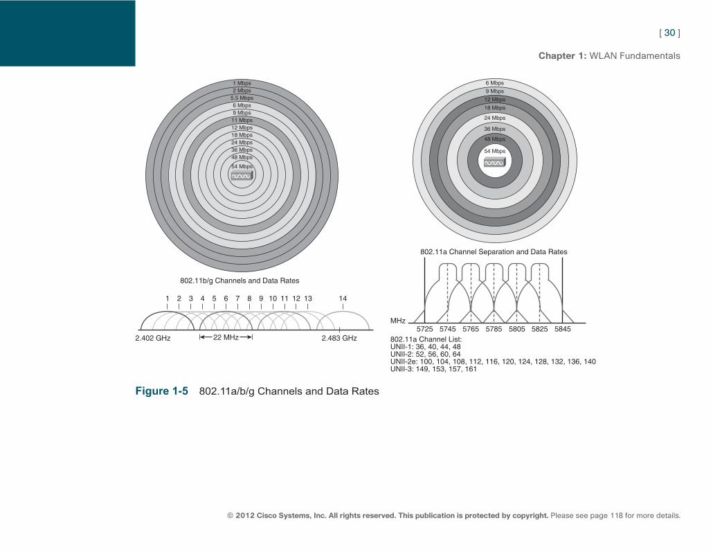
802.11a Beyond the issue related to 802.11b client protection, the 2.4 GHz band also suffers from the fact that it is an ISM band. Many other non-802.11 devices use the same frequency bands and create interference issues for the 2.4 GHz 802.11 devices. This problem was very apparent as soon as the first 802.11 standard was published. To remediate this issue, the 802.11a amendment was published in 1999 (the same year as 802.11b, and four years before 802.11g!). 802.11a uses OFDM only (6 Mbps to 54 Mbps). The big change is that 802.11a uses a band (new at that time) dedicated to WLAN in the 5 GHz spectrum. This was the beginning of the four bands described earlier. Because the channels in the 5 GHz are already nonoverlapping, 802.11a offers up to 23 nonoverlapping channels. Channels are 20 MHz apart, which is enough for the 20 MHz wide OFDM channels. Yet, the recommendation is to leave at least one channel separation when using two channels in the same physical space (using, for example, channel 36 and 44 but not 40 in the same area). As the band is used almost only for wireless, the 5 GHz band suffers less from interferences than the 2.4 GHz band. Why isn’t everyone using 802.11a then? Simply because supporting 802.11b allows keeping the 802.11 clients, and supporting 802.11g allows keeping the 802.11b clients. Supporting 802.11a implies replacing all APs and all clients, which made the adoption of 802.11a slow. 802.11a is a lot more frequent in enterprise networks (where you commonly find dual-band 2.4 GHz and 5 GHz APs) than in consumer networks.
ptg7913109
[ 30 ]
© 2012 Cisco Systems, Inc. All rights reserved. This publication is protected by copyright. Please see page 118 for more details.
Chapter 1: WLAN Fundamentals
1 Mbps2 Mbps
5.5 Mbps6 Mbps9 Mbps11 Mbps12 Mbps18 Mbps24 Mbps36 Mbps48 Mbps
54 Mbps
1
6 Mbps
9 Mbps
12 Mbps
18 Mbps
24 Mbps
36 Mbps
48 Mbps
54 Mbps
2 3 4 5 6 7 8 9
802.11b/g Channels and Data Rates
802.11a Channel Separation and Data Rates
802.11a Channel List:UNII-1: 36, 40, 44, 48UNII-2: 52, 56, 60, 64UNII-2e: 100, 104, 108, 112, 116, 120, 124, 128, 132, 136, 140UNII-3: 149, 153, 157, 161
5725 5745 5765 5785 5805 5825 5845
10 11 12 13
2.483 GHz
MHz
2.402 GHz
14
22 MHz
Figure 1-5 802.11a/b/g Channels and Data Rates
ptg7913109
[ 31 ]
© 2012 Cisco Systems, Inc. All rights reserved. This publication is protected by copyright. Please see page 118 for more details.
Chapter 1: WLAN Fundamentals
802.11n 802.11n was published in 2009 and aims at increasing the speed beyond 54 Mbps. 802.11n describes three sets of techniques, most of which can be implemented to improve 802.11g or 802.11a:
■ Channel aggregation: 802.11n allows for 40 MHz-wide channels, bonding two 20 MHz separated channels (36 and 40, for example, or 1 and 5). Within this larger channel, subcarriers that were previously unused can be used for data transmission, creating a 119 Mbps data rate channel. Channel aggregation is not recommended for the 2.4 GHz band because too few channels are available in that band for bonding to improve the spectrum. Using a 40 MHz channel also consumes more energy than using a 20 MHz channel. For this reason, many portable consumer devices (phones, tablets) do not support channel bonding.
■ MAC efficiency mechanisms were added: For example, stations can send burst of frames that are all acknowledged in one frame after the burst, thus reducing the nondata overhead. Another mechanism is to use a shorter guard interval (the silence between two symbols in a wave), 400 nanoseconds (ns) instead of 800 ns. This process increases the speed by 11%, but also increases the risk of collisions in noisy environments.
■ MIMO (multiple in, multiple out) is the most publicized mechanism. 802.11n stations can have several radios on the same channel and use them at the same time. This allows for several possible improvements:
■ The emitter can send the same signal from several antennas. By carefully coordinating these signals based on the feedback transmitted by the 802.11n receiving station, the emitter aims at making these signals be received in phase, thus increasing the signal power level at the receiving station, allowing for longer range or higher throughput. This process is called Transmit Beamforming (TxBF).
■ The emitter can also send different simultaneous signals from different radios. The 802.11n receiver will receive these signals on all its radios. Each of the receive radios independently decode the arriving signals. Then, each receive signal is combined with the signals from the other radios. This results in additional throughput. This process is called spatial multiplexing .
■ Because of multipath, a signal travels along different paths before reaching the receiver. With a technique called Multi Ratio Combining (MRC), the receiver can combine the signals received on each antenna and radio chain, resulting in a stronger received signal, again increasing range or speed.
ptg7913109
[ 32 ]
© 2012 Cisco Systems, Inc. All rights reserved. This publication is protected by copyright. Please see page 118 for more details.
Chapter 1: WLAN Fundamentals
TxBF implies a feedback from an 802.11n receiver. To also help improve signals for non-802.11n clients, Cisco 802.11n APs use a mechanism called ClientLink, by which the AP uses the signal received from the non-802.11n client on its various radio chains, performs the MRC calculation to optimize the signal reception, and uses the same calculation to synchronize its signals when responding to the client. This technique improves the non-802.11n client up to 40% in distance or throughput. Notice that the client must be OFDM to benefit from this technology. Cisco APs use this technique automatically for 802.11a clients, as soon as their RSSI falls below –60 dBm, and for 802.11g clients when their RSSI falls below –50 dBm. An AP can support up to 15 ClientLink clients at a time.
All these techniques enable 802.11n stations to achieve a data rate of up to 144 Mbps when using two streams (two radio chains), short guard intervals and 20 MHz channels, and 300 MHz when using two streams (two radio chains), short guard intervals and 40 MHz channels. Notice that, just like for the previous protocols, these rates represent the best transmission speed that a station can achieve, not the overall throughput (or “download speed”), because 802.11 is half duplex and because some airtime is also used by nondata frames and silences. To avoid the confusion between data rate as in “transmission speed” with data rate as in “download speed,” data rates were renamed modulation and coding scheme (MCS) for 802.11n.
802.11 Frames
Medium Access Regardless of the version of the protocol they use, wireless devices try to avoid collisions. Collisions occur when two devices send at the same time. Collisions are avoided by using a contention mechanism. No central device decides which frame is transmitted first; instead, each device takes care of itself. This noncentralized access method is called Distributed Coordination Function (DCF). Stations always listen to the medium and refrain from sending if another station signal is detected. After a frame is completely sent, there is always a silence to allow for the multipath issues to clear. The length of this silence is determined by the priority of the frame:
■ If the frame that is being sent has a high priority, the station waits for a period of time called a Short Interframe Space (SIFS).
■ If the packet has a standard priority, the station waits for a period of time called a Distributed Interframe Space (DIFS), which is the normal timer that is used in DCF networks.
■ Other interframe spaces exist, such as the Reduced Interframe Space (RIFS) used by 802.11n station between each segment of a burst.
ptg7913109
[ 33 ]
© 2012 Cisco Systems, Inc. All rights reserved. This publication is protected by copyright. Please see page 118 for more details.
Chapter 1: WLAN Fundamentals
To avoid collisions, devices in the cell use carrier sense multiple access with collision avoidance (CSMA/CA). When a device needs to send a data frame, it starts by picking a random number between 0 and 31 (typically 31). It then counts down from that number. The speed at which the countdown occurs depends on the network (20 microseconds per number for IEEE 802.11b, 9 microseconds per number for 802.11g and 802.11a; this speed rhythm is called the slot time ). The total amount of microseconds in the picked-up countdown value is called the backoff timer .
When the station detects a frame being transmitted over the air during the countdown, it stops counting and resumes the countdown after the detected frame is completely sent. The frame header, if readable, contains the duration of the frame transmission, the network allocation vector (NAV). The detecting station can also add the NAV to its countdown value and continue counting down from the new total. The total amount of time waited (backoff time plus time waited during transmissions) is called the contention window (the time during which the station refrains from sending). When the counter reaches zero, the station sends its frame, assuming the media is free.
Because WLANs are half duplex, a station cannot receive while sending, so it does not know whether its transmission went through or was corrupted. For this reason, unicast frames are always acknowledged by the destination station. The receiver waits a SIFS, and then sends an acknowledgment message back to the sender. Notice that broadcast and multicast frames are not acknowledged.
If the frame transmission failed, the station picks a number that is the double from its original number (for example, 62 if the first number was 31), waits a DIFS, and then restarts counting from that new number. The number doubles for each failed attempts, to a maximum of 1023. Every new attempt will then use 1023.
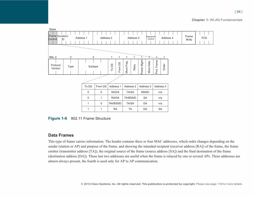
Frame Types All 802.11 frames have a similar structure, as shown in Figure 1-6 . They start with a preamble (72 bits or 144 bits long), followed by a “frame control” field (2 bytes long [16 bits]), mentioning among other parameters the frame type (management, control, data) and subtype, a duration field, expressing how long the medium is reserved (2 bytes long [16 bits]), MAC addresses, optional QoS or 802.11n information, the frame body (2304 bytes max by default, can be extended with 802.11n), and a 4-byte frame check sequence (FCS). The total length of the frame is, by default, 2346 bytes maximum. The content of the body depends on the frame type and purpose. There are three types of frames: management, control, and data.
ptg7913109
[ 34 ]
© 2012 Cisco Systems, Inc. All rights reserved. This publication is protected by copyright. Please see page 118 for more details.
Chapter 1: WLAN Fundamentals
FrameFCS
BodySequence
Control Address 4Address 3Address 2Address 1
To DS From DS Address 1 Address 2 Address 3 Address 4
0 0 RA/DA TA/SA BSSID n/a
0 1 RA/DA TA/BSSID SA n/a
1 0 RA/BSSID TA/SA DA n/a
1 1 RA TA DA SA
Duration/ID
ProtocolVersion
Type Subtype
To
DS
Fro
m D
S
Mor
e F
rag
Pow
er M
gmt
Mor
e D
ata
Pro
t. F
ram
e
Ord
er
Ret
ry
FrameControl
Bytes
Bits 2 2 4 1 1 1 1 1 1 1 1
Figure 1-6 802.11 Frame Structure
Data Frames This type of frame carries information. The header contains three or four MAC addresses, which order changes depending on the sender (station or AP) and purpose of the frame, and showing the intended recipient (receiver address [RA]) of the frame, the frame emitter (transmitter address [TA]), the original source of the frame (source address [SA]) and the final destination of the frame (destination address [DA]). These last two addresses are useful when the frame is relayed by one or several APs. Three addresses are almost always present, the fourth is used only for AP to AP communication.
ptg7913109
[ 35 ]
© 2012 Cisco Systems, Inc. All rights reserved. This publication is protected by copyright. Please see page 118 for more details.
Chapter 1: WLAN Fundamentals
Management Frames Management frames contain information about the BSA or the communication parameters and help manage the cell. The following are the main management frames you must be familiar with:
■ Beacons: In a BSS, these frames are broadcasted by the AP at the lowest mandatory rate supported by the cell, every 100 TU (102.4 ms) by default. These frames contain information about the WLAN, including the SSID (this element can be set to Null, thus hiding the SSID), the rates allowed in the cell, and also sometimes vendor-specific information.
■ Probe requests and responses: Devices can send probe requests to the broadcast address or the AP MAC address to ask about the WLAN characteristics. The AP responds with probe response frames that contain the same information as the beacon (the TIM field, specific to the beacon frame, being the exception).
■ Authentication: When a client decides to join the cell, it sends an authentication request frame, and the AP replies with an authentication response frame. The response may be a direct authentication success when open authentication is used, or contain a challenge phase when WEP authentication is used.
■ Association: When the authentication phase is complete, the client asks to join the cell with an association request, and the AP replies with an association response that contains a client identifier (a unique number for that client in the cell).
■ Deassociation, reassociation, deauthentication: At any time, the client can leave the cell or the AP can disconnect a client by sending a deassociation or a deauthentication message. A client that has briefly left the WLAN (or roamed) can attempt to re-join the WLAN with a reassociation request message. The AP answers with a reassociation response.
Control Frames Control frames are special messages used in the cell to improve the efficiency of the connection. The ACK frame is used to acknowledge unicast frames. Request to Send/Clear to send (RTS/CTS) is used for protection against collisions in two cases:
■ When 802.11b clients are present in a 802.11g cell: An 802.11g station sends an RTS message at 802.11b speed, and the receiver replies with a CTS at 802.11b speed; the 802.11b station will hear the duration field in the RTS or the CTS and will stay silent while the communication occurs at 802.11g rate.
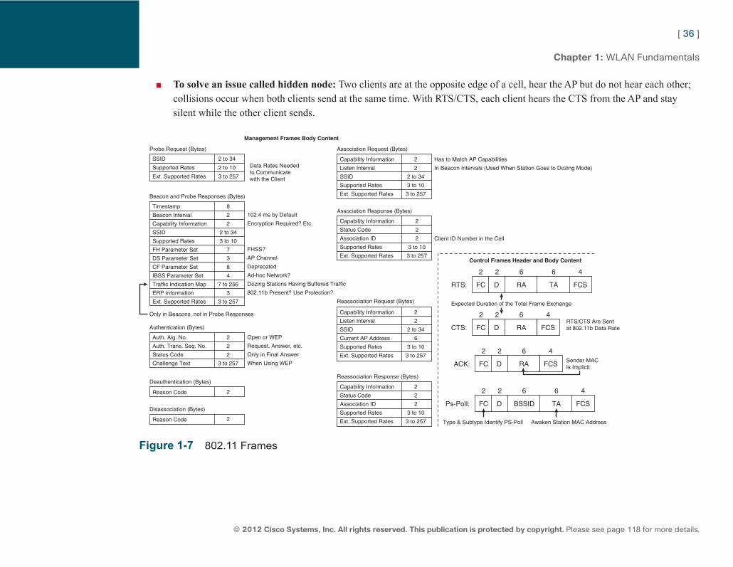
ptg7913109
[ 36 ]
© 2012 Cisco Systems, Inc. All rights reserved. This publication is protected by copyright. Please see page 118 for more details.
Chapter 1: WLAN Fundamentals
■ To solve an issue called hidden node: Two clients are at the opposite edge of a cell, hear the AP but do not hear each other; collisions occur when both clients send at the same time. With RTS/CTS, each client hears the CTS from the AP and stay silent while the other client sends.
Probe Request (Bytes)
Control Frames Header and Body Content
Management Frames Body Content
Association Request (Bytes)
Association Response (Bytes)
Reassociation Request (Bytes)
Reassociation Response (Bytes)
Beacon and Probe Responses (Bytes)
Only in Beacons, not in Probe Responses
Authentication (Bytes)
Deauthentication (Bytes)
Disassociation (Bytes)
SSIDData Rates Neededto Communicatewith the Client
102.4 ms by Default
Encryption Required? Etc.
Has to Match AP Capabilities
In Beacon Intervals (Used When Station Goes to Dozing Mode)
Client ID Number in the Cell
FCRTS:
Expected Duration of the Total Frame Exchange
RTS/CTS Are Sentat 802.11b Data Rate
Type & Subtype Identify PS-Poll Awaken Station MAC Address
Sender MACIs Implicit
D RA TA FCS
2 2 6 6 4
FHSS?
AP Channel
Deprecated
Ad-hoc Network?
Dozing Stations Having Buffered Traffic
802.11b Present? Use Protection?
Open or WEP
Request, Answer, etc.
Only in Final Answer
When Using WEP
Timestamp
Beacon Interval
Capability Information
SSID
Supported Rates
FH Parameter Set
DS Parameter Set
CF Parameter Set
IBSS Parameter Set
Traffic Indication Map
ERP Information
Ext. Supported Rates
Capability Information
Listen Interval
SSID
Supported Rates
Ext. Supported Rates
Capability Information
Status Code
Association ID
Supported Rates
Ext. Supported Rates
Capability Information
Listen Interval
SSID
Current AP Address
Supported Rates
Ext. Supported Rates
Capability Information
Status Code
Association ID
Supported Rates
Ext. Supported Rates
2
2
2 to 34
3 to 10
3 to 257
2
2
2
3 to 10
3 to 257
2
2
2 to 34
6
3 to 10
3 to 257
2
2
2
3 to 10
3 to 257
Auth. Alg. No.
Auth. Trans. Seq. No.
Status Code
Challenge Text
Reason Code
Reason Code
8
2
2
2 to 34
3 to 10
7
3
8
4
7 to 256
3
3 to 257
2
2
2
3 to 257
2
2
Supported Rates
Ext. Supported Rates
2 to 34
2 to 10
3 to 257
FCPs-PolI: D BSSID TA FCS
2 2 6 6 4
FCCTS: D RA FCS
2 2 6 4
FCACK: D RA FCS
2 2 6 4
Figure 1-7 802.11 Frames
ptg7913109
[ 37 ]
© 2012 Cisco Systems, Inc. All rights reserved. This publication is protected by copyright. Please see page 118 for more details.
Chapter 1: WLAN Fundamentals
Frame Rates Each protocol implements mandatory and supported rates. Mandatory means that the client must be able to perform that modulation to be allowed in the cell. Supported means that the client can join the cell even if its NIC cannot achieve that modulation and rate. With 802.11b/g/n, 1, 2, 5.5, and 11 Mbps are mandatory by default. With 802.11a/n, 6, 12, and 24 Mbps are mandatory by default. These defaults are configurable on the AP, and the joining client adapts to the rates defined by the AP for the cell. You can even disable some rates (unused in that cell). By default, broadcast management frames and RTS/CTS are always sent at the lowest mandatory rate. Data frames and unicast management frames are sent at the optimal rate determined by the emitter based on the receiver last signal RF values (RSSI, SNR, frame error rate). ACKs are sent at the first mandatory rate below that optimal rate (for example, 24 Mbps if the optimal rate was determined as 36 Mbps, in a default 802.11a network).
Power Save To save battery power, a device that has the power saving mode will snooze when it has nothing to send and is not expecting a frame, and will wake up periodically to listen to the AP messages. The station starts by sending a null (empty data frame) with a header Power Management bit set to 1, informing the AP that the station goes to dozing mode. The AP then buffers subsequent incoming traffic for this station. In each beacon, a field called Traffic Indication Map (TIM) lists the stations for which the AP has traffic buffered. Some beacons contain a field called the Delivery Traffic Indication Map (DTIM) that indicates whether the AP has broadcast or multicast buffered traffic. The AP indicates in its beacons how often the DTIM beacon is sent, and dozing stations should wake up at least for each DTIM. If the AP has a DTIM set to 1, the awaken stations stay awake and the AP sends the broadcast just after the beacon bearing a positive DTIM.
For unicast traffic, stations hearing their AID in the TIM send a Power Save (PS) Poll control frame to ask for the buffered frames. The AP sends the first buffered frame, with the More Data control field bit set to 1 if more data is buffered. The station sends a new PS Poll frame for the next frame, and the process repeats until the AP buffered is emptied.
ptg7913109
[ 38 ]
© 2012 Cisco Systems, Inc. All rights reserved. This publication is protected by copyright. Please see page 118 for more details.
Chapter 1: WLAN Fundamentals
WMM This default power save mechanism is often seen as inefficient, because it consumes many frames and airtime. In 2005, the IEEE published the 802.11e amendment to design mechanisms to introduce QoS and prioritization mechanisms in 802.11. 802.11e also implements an improved power save mechanism, called Automatic Power Save Delivery (APSD), existing in two versions, Unscheduled APSD (U-APSD), which is the most frequent, and Scheduled APSD (S-APSD). With these mechanisms, the station can inform the AP of its dozing or waking state with any frame with the Power Management bit properly set (0 or 1), and APs empty their buffer in bursts.
802.11e also creates four QoS queues: Platinum (for urgent traffic, such as voice), Gold (less urgent, such as video), Silver (standard priority), and Bronze (background, non-urgent traffic). A station uses internal parallel queues and picks up a random backoff timer in a shorter range for the more urgent traffic, thus maximizing the chances that the urgent traffic will reach 0 first. When sending, the QoS station does not use the DIFS, but the Arbitration Interframe Space (AIFS), which is shorter for more urgent traffic: If two stations’ counters pick up the same number at the same time, the station sending more urgent traffic will send first.
802.11e offers these features through two main QoS schemes. The simpler is called Enhanced Distributed Channel Access (EDCA), the more complex is called Hybrid Coordinator Function Controlled Channel Access (HCCCA). The Wi-Fi Alliance published the Wireless Multi Media (WMM) Power Save certification for stations implementing these features in EDCA.
Non-802.11 Technologies The 802.11 preamble and headers are the elements that allow stations to understand each other’s traffic. Other devices may use the same frequency ranges, but because they lack the 802.11 header, they are incompatible with 802.11 and are seen as interference and noise by 802.11 devices. Common technologies using the same RF bands are as follows:
■ Bluetooth is an FHSS WPAN technology operating in the 2.4-GHz band under the IEEE 802.15.1 protocol. A given Bluetooth device creates a slave and master relationship where one or several slaves provide a service to the master. Bluetooth devices are not compatible with 802.11 devices. Most Bluetooth devices use class 2 (2.5 mW) or class 3 (1 mW) power levels and are not a major source of interference for 802.11 networks. Industrial class 1 (100 mW) Bluetooth devices heavily interfere with 802.11 networks, but they are uncommon.
ptg7913109
[ 39 ]
© 2012 Cisco Systems, Inc. All rights reserved. This publication is protected by copyright. Please see page 118 for more details.
Chapter 1: WLAN Fundamentals
■ Cordless (Digital Enhanced [formerly European] Cordless Telecommunications, or DECT) phones may be using the 2.4 GHz ISM band or the 5.8 GHz ISM band. They are not 802.11 devices, and use a technology derived from ISDN to provide slots of times on the same frequency to different calling stations. They have the capability to jump from one frequency to the other when needed for better communication. Their power level is usually low (10 mW) but can spike to 250 mW. They are a significant source of interference to 802.11 networks.
■ ZigBee is based on the IEEE 802.15.4 protocol for WPAN, and aims at developing hardware and applications with a low data rate but also low power consumption and low complexity—for example, to control sensors. ZigBee-based products can access up to 16 separate 5 MHz channels in the 2.4 GHz band and are not compatible with 802.11 devices. The maximum power of ZigBee is 60 mW. Devices use low consumption most of the time but can spike when needed: The impact on wireless networks can then be significant.
■ WiMAX does not operate in the 802.11 bands and typically uses licensed frequencies, but many describe it as the future for wireless. In fact, WiMAX uses another family of standards, 802.16, and is incompatible with 802.11. The IEEE 802.11 working group is planning to extend 802.11 to other frequencies, so it is unlikely that WiMAX will replace 802.11 soon. WiMAX has several bands of operations and several modes (backbone for long-range links or last mile for end-user links—those modes usually are not compatible with each other). WiMAX does not interact or interfere with 802.11 networks, although some outdoor mesh APs can be equipped with dual modules, allowing, for example, WiMAX to be used as a link to the core network (backbone link) and 802.11 for the wireless client access. The AP would use a specific application to translate between 802.11 and 802.16.
ptg7913109
[ 40 ]
© 2012 Cisco Systems, Inc. All rights reserved. This publication is protected by copyright. Please see page 118 for more details.
CCNA Wireless (640-722 IUWNE) Quick Reference
Chapter 2 Install a Basic Cisco WLAN One major concern when implementing an IEEE 802.11 wireless network is the ability to monitor and maintain the network. Managing a wireless network implies configuring SSID and related parameters (security, associated VLAN, and so on), managing roaming and credential transmission from one AP to another, and managing the channels and transmit power of APs to ensure optimal coverage. In small environments, the administrator can configure the APs individually for these elements. Larger networks require a central device where configuration is performed and pushed to the APs. For this reason, the Cisco Unified Wireless networking solution offers two types of APs:
■ Standalone (autonomous) APs: Can be configured one by one and offer full functionality by themselves (they are well adapted for small deployments.
■ Lightweight APs: Rely on a central WLAN controller where the configuration is managed. Most APs can be converted from one mode to the other depending on the specific deployment needs.
CAPWAP The controller-based solution allows the splitting of 802.11 functions between the controller-based AP, which handles real-time portions of the standard, and the Cisco WLC, which handles items that are not time sensitive. This model is called split MAC .
The AP handles the portions that have real-time requirements, such as the following:
■ Beacons management
■ 802.11 encryption and decryption
■ Frame buffering for dozing stations
ptg7913109
[ 41 ]
© 2012 Cisco Systems, Inc. All rights reserved. This publication is protected by copyright. Please see page 118 for more details.
Chapter 2: Install a Basic Cisco WLAN
■ Probe responses
■ Air monitoring for interferences and rogues
The controller handles all other functionalities, such as the following:
■ 802.11 authentication and association
■ QoS and security management
■ Mobility (roaming) management
■ RF management
■ Bridging to and from the DS in the right VLAN
Lightweight APs (LAP) communicate with the controller using a specific protocol, Control and Provisioning of Wireless Access Points (CAPWAP). The LAP encapsulates all 802.11 data frames received from a client into a CAPWAP frame. The data frame portion is simply encapsulated into a CAPWAP frame, and is not encrypted by default (data part encryption is possible but optional).
The LAPs also constantly exchange encrypted CAPWAP control messages with the controller via the Radio Resource Management (RRM) engine for real-time RF management, including
■ Radio resource monitoring
■ Dynamic channel assignment
■ Interference detection and avoidance
■ Dynamic transmit power control
■ Coverage hole detection
■ Correction and client and network load balancing
ptg7913109
[ 42 ]
© 2012 Cisco Systems, Inc. All rights reserved. This publication is protected by copyright. Please see page 118 for more details.
Chapter 2: Install a Basic Cisco WLAN
The controller examines several real-time RF characteristics, such as the following:
■ Access point received energy
■ Noise
■ 802.11 interference
■ Utilization
■ Client load
The controller examines these characteristics around each AP in a 3D space, to make systemwide decisions. The controller can decrease the AP power (when a neighboring AP signal is too high), increase the AP power (when a coverage hole is detected), change the AP channel to avoid interferences, and load balance clients between APs.
Hardware Components The Cisco Unified Wireless Network is composed of five interconnected elements that work together to deliver a unified enterprise-class wireless solution:
■ Client devices
■ APs
■ Network unification
■ Network management
■ Network services
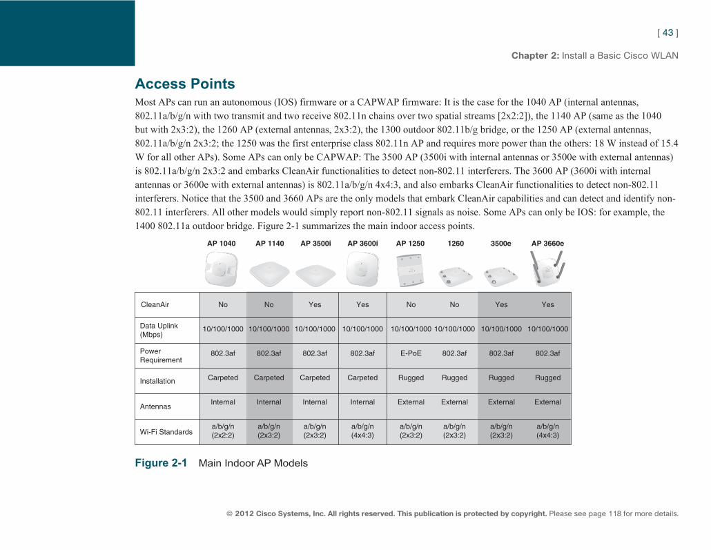
ptg7913109
[ 43 ]
© 2012 Cisco Systems, Inc. All rights reserved. This publication is protected by copyright. Please see page 118 for more details.
Chapter 2: Install a Basic Cisco WLAN
Access Points Most APs can run an autonomous (IOS) firmware or a CAPWAP firmware: It is the case for the 1040 AP (internal antennas, 802.11a/b/g/n with two transmit and two receive 802.11n chains over two spatial streams [2x2:2]), the 1140 AP (same as the 1040 but with 2x3:2), the 1260 AP (external antennas, 2x3:2), the 1300 outdoor 802.11b/g bridge, or the 1250 AP (external antennas, 802.11a/b/g/n 2x3:2; the 1250 was the first enterprise class 802.11n AP and requires more power than the others: 18 W instead of 15.4 W for all other APs). Some APs can only be CAPWAP: The 3500 AP (3500i with internal antennas or 3500e with external antennas) is 802.11a/b/g/n 2x3:2 and embarks CleanAir functionalities to detect non-802.11 interferers. The 3600 AP (3600i with internal antennas or 3600e with external antennas) is 802.11a/b/g/n 4x4:3, and also embarks CleanAir functionalities to detect non-802.11 interferers. Notice that the 3500 and 3660 APs are the only models that embark CleanAir capabilities and can detect and identify non-802.11 interferers. All other models would simply report non-802.11 signals as noise. Some APs can only be IOS: for example, the 1400 802.11a outdoor bridge. Figure 2-1 summarizes the main indoor access points.
AP 1040 AP 1140 AP 3500i AP 3600i AP 1250 1260 3500e AP 3660e
CleanAir
Data Uplink(Mbps)
PowerRequirement
Installation
Antennas
Wi-Fi Standards
10/100/1000
802.3af
Carpeted
Internal
a/b/g/n(2x2:2)
10/100/1000
802.3af
Carpeted
Internal
a/b/g/n(2x3:2)
10/100/1000
802.3af
Carpeted
Internal
a/b/g/n(2x3:2)
10/100/1000
802.3af
Carpeted
Internal
a/b/g/n(4x4:3)
10/100/1000
E-PoE
Rugged
External
a/b/g/n(2x3:2)
10/100/1000
802.3af
Rugged
External
a/b/g/n(2x3:2)
10/100/1000
802.3af
Rugged
External
a/b/g/n(2x3:2)
10/100/1000
802.3af
Rugged
External
a/b/g/n(4x4:3)
No No Yes Yes Yes YesNo No
Figure 2-1 Main Indoor AP Models
ptg7913109
[ 44 ]
© 2012 Cisco Systems, Inc. All rights reserved. This publication is protected by copyright. Please see page 118 for more details.
Chapter 2: Install a Basic Cisco WLAN
Controllers WLAN controllers (WLC) control CAPWAP APs and exist as appliances or modules to integrate in routers or switches. The main difference between the units resides in the number of APs supported, from 5 to 500 per unit. For most platforms, the number of supported APs is license-based and can be increased when needed.
Appliance Controllers The 5508 controller is a 1 RU appliance that can support 12, 25, 50, 100, 250, or 500 APs. This controller has 8 Gbps ports.
The 4400 (4402 for 12, 25, or 50 AP support with 2 Gbps ports, and 4404 for 100 AP support with 4 Gbps port) is an older 1 RU appliance model.
The 2504 controller is a small to medium-sized enterprise and branch office entry-level controller, supporting 5, 15, 25, or 50 APs with 4 Gbps ports.
The 2100 controller (model 2106, 2112, or 2125 for 6, 12, or 25 APs, respectively) is an older entry-level controller, with eight 100 Mbps ports.
The Cisco Flex 7500 Series Controller has two 10GE fiber ports and is designed specifically to manage FlexConnect (HREAP) APs. This WLC supports between 500 and 2000 HREAP APs.
Controller Modules The Cisco Catalyst 6500 Wireless Services Module (WiSM) is a blade that uses the Catalyst 6500 Series chassis to provide power and network connectivity (2x4 Gbps). The Cisco WiSM supports 150 APs per controller, and each blade contains two controllers (300 APs per blade). You can cluster up to 12 blades (allowing up to 3600 APs per cluster).
The Cisco WiSM-2 is the next-generation wireless service module for the Cisco Catalyst 6500 or Catalyst 7600 Series chassis. The Cisco WiSM-2 can support a total of 500 APs on a single controller interface (this number was later increased but is still valid for the IUWNE exam). You can cluster up to 24 blades (12,000 APs per cluster). The WiSM2 supports the incremental licensing model (100, 300, or 500 APs) and provides a throughput of 10 Gbps to the Catalyst switch.
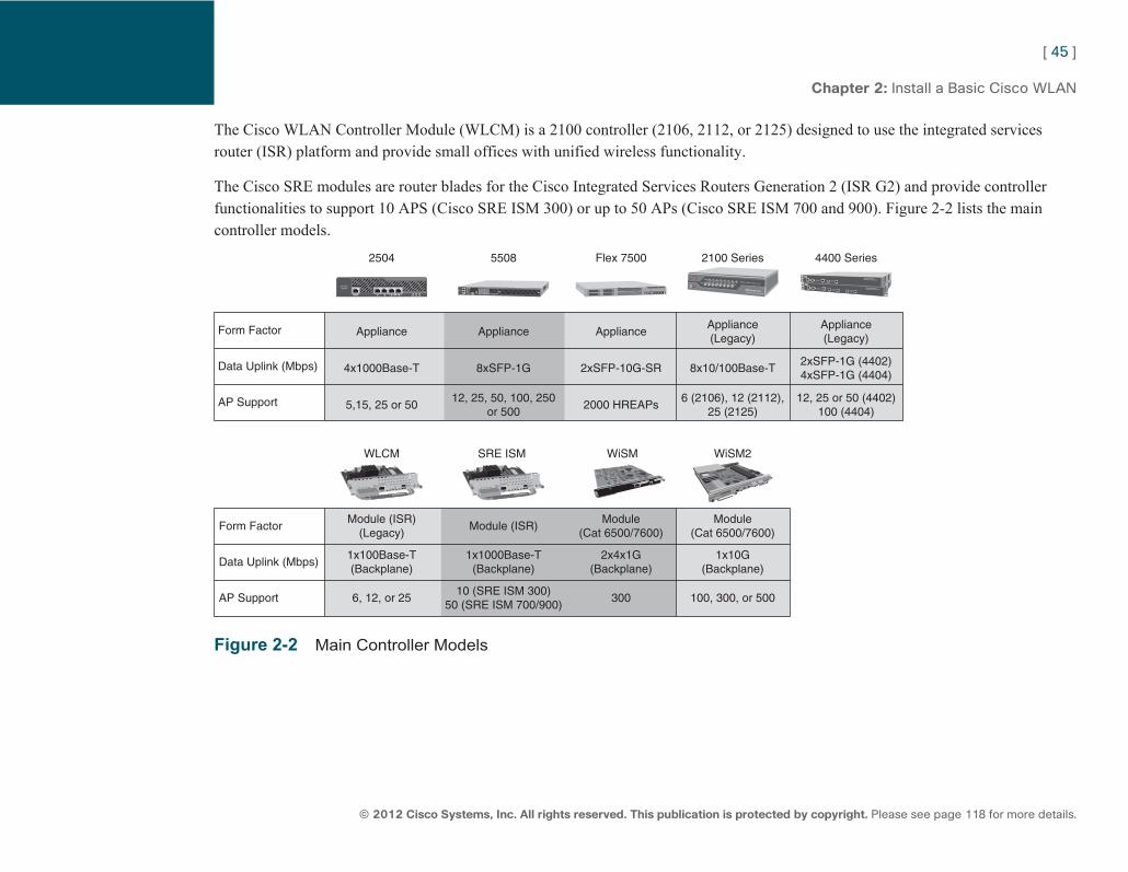
ptg7913109
[ 45 ]
© 2012 Cisco Systems, Inc. All rights reserved. This publication is protected by copyright. Please see page 118 for more details.
Chapter 2: Install a Basic Cisco WLAN
The Cisco WLAN Controller Module (WLCM) is a 2100 controller (2106, 2112, or 2125) designed to use the integrated services router (ISR) platform and provide small offices with unified wireless functionality.
The Cisco SRE modules are router blades for the Cisco Integrated Services Routers Generation 2 (ISR G2) and provide controller functionalities to support 10 APS (Cisco SRE ISM 300) or up to 50 APs (Cisco SRE ISM 700 and 900). Figure 2-2 lists the main controller models.
2504 5508 Flex 7500 2100 Series 4400 Series
Form Factor
Data Uplink (Mbps)
AP Support
Appliance
4x1000Base-T
5,15, 25 or 50
Appliance
8xSFP-1G
12, 25, 50, 100, 250or 500
Appliance
2xSFP-10G-SR
2000 HREAPs
Appliance(Legacy)
8x10/100Base-T
6 (2106), 12 (2112),25 (2125)
Appliance(Legacy)
2xSFP-1G (4402)4xSFP-1G (4404)
12, 25 or 50 (4402)100 (4404)
WLCM SRE ISM WiSM WiSM2
Form Factor
Data Uplink (Mbps)
AP Support
Module (ISR)(Legacy)
1x100Base-T(Backplane)
6, 12, or 25
Module (ISR)
1x1000Base-T(Backplane)
10 (SRE ISM 300)50 (SRE ISM 700/900)
Module(Cat 6500/7600)
2x4x1G(Backplane)
300
Module(Cat 6500/7600)
1x10G(Backplane)
100, 300, or 500
Figure 2-2 Main Controller Models
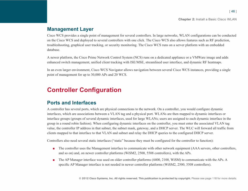
ptg7913109
[ 46 ]
© 2012 Cisco Systems, Inc. All rights reserved. This publication is protected by copyright. Please see page 118 for more details.
Chapter 2: Install a Basic Cisco WLAN
Management Layer Cisco WCS provides a single point of management for several controllers. In large networks, WLAN configurations can be conducted on the Cisco WCS and deployed to several controllers with one click. The Cisco WCS also allows features such as RF prediction, troubleshooting, graphical user tracking, or security monitoring. The Cisco WCS runs on a server platform with an embedded database.
A newer platform, the Cisco Prime Network Control System (NCS) runs on a dedicated appliance or a VMWare image and adds enhanced switch management, unified client tracking with ISE/MSE, streamlined user interface, and dynamic RF heatmaps.
In an even larger environment, Cisco WCS Navigator allows navigation between several Cisco WCS instances, providing a single point of management for up to 30,000 APs and 20 WCS.
Controller Configuration
Ports and Interfaces A controller has several ports, which are physical connections to the network. On a controller, you would configure dynamic interfaces, which are associations between a VLAN tag and a physical port. WLANs are then mapped to dynamic interfaces or interface groups (groups of several dynamic interfaces, used for large WLANs; users are assigned to each dynamic interface in the group in a round robin fashion). When configuring dynamic interfaces on the controller, you must enter the associated VLAN tag value, the controller IP address in that subnet, the subnet mask, gateway, and a DHCP server. The WLC will forward all traffic from clients mapped to that interface to that VLAN and subnet and relay the DHCP queries to the configured DHCP server.
Controllers also need several static interfaces (“static” because they must be configured for the controller to function):
■ The controller uses the Management interface to communicate with other network equipment (AAA servers, other controllers, and so on) and, on newer controller platforms (WiSM2, 2500, 5508 controllers), with the APs.
■ The AP Manager interface was used on older controller platforms (4400, 2100, WiSM) to communicate with the APs. A specific AP Manager interface is not needed in newer controller platforms (WiSM2, 2500, 5508 controllers).
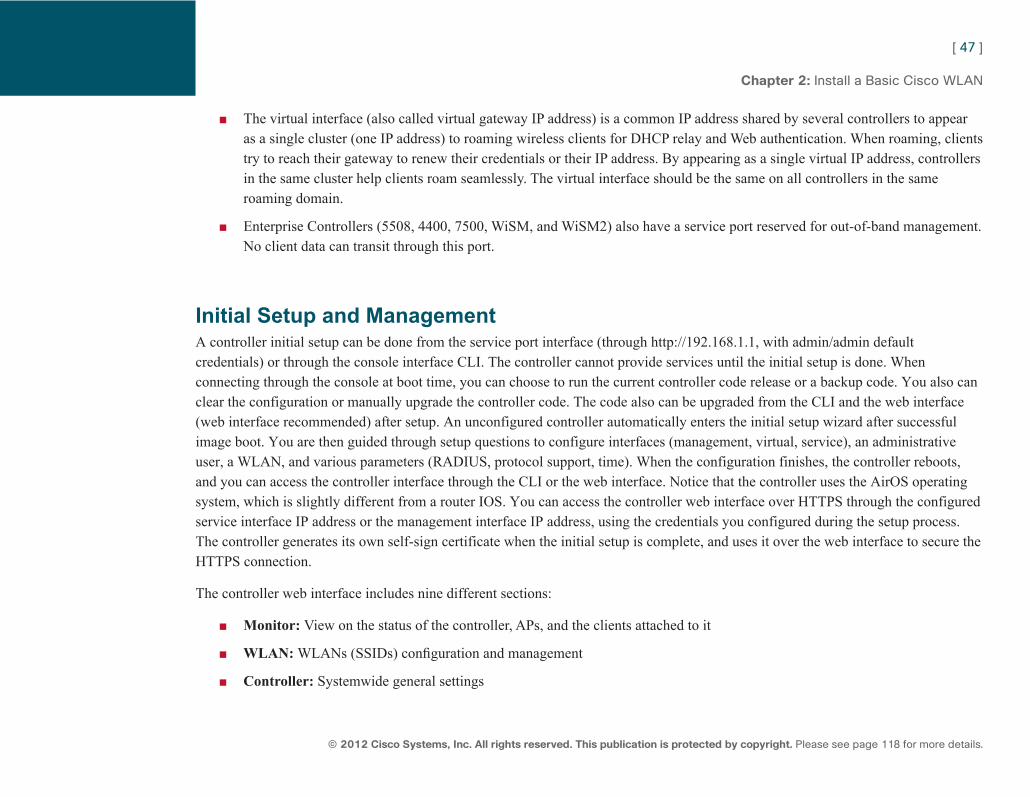
ptg7913109
[ 47 ]
© 2012 Cisco Systems, Inc. All rights reserved. This publication is protected by copyright. Please see page 118 for more details.
Chapter 2: Install a Basic Cisco WLAN
■ The virtual interface (also called virtual gateway IP address) is a common IP address shared by several controllers to appear as a single cluster (one IP address) to roaming wireless clients for DHCP relay and Web authentication. When roaming, clients try to reach their gateway to renew their credentials or their IP address. By appearing as a single virtual IP address, controllers in the same cluster help clients roam seamlessly. The virtual interface should be the same on all controllers in the same roaming domain.
■ Enterprise Controllers (5508, 4400, 7500, WiSM, and WiSM2) also have a service port reserved for out-of-band management. No client data can transit through this port.
Initial Setup and Management A controller initial setup can be done from the service port interface (through http://192.168.1.1, with admin/admin default credentials) or through the console interface CLI. The controller cannot provide services until the initial setup is done. When connecting through the console at boot time, you can choose to run the current controller code release or a backup code. You also can clear the configuration or manually upgrade the controller code. The code also can be upgraded from the CLI and the web interface (web interface recommended) after setup. An unconfigured controller automatically enters the initial setup wizard after successful image boot. You are then guided through setup questions to configure interfaces (management, virtual, service), an administrative user, a WLAN, and various parameters (RADIUS, protocol support, time). When the configuration finishes, the controller reboots, and you can access the controller interface through the CLI or the web interface. Notice that the controller uses the AirOS operating system, which is slightly different from a router IOS. You can access the controller web interface over HTTPS through the configured service interface IP address or the management interface IP address, using the credentials you configured during the setup process. The controller generates its own self-sign certificate when the initial setup is complete, and uses it over the web interface to secure the HTTPS connection.
The controller web interface includes nine different sections:
■ Monitor: View on the status of the controller, APs, and the clients attached to it
■ WLAN: WLANs (SSIDs) configuration and management
■ Controller: Systemwide general settings
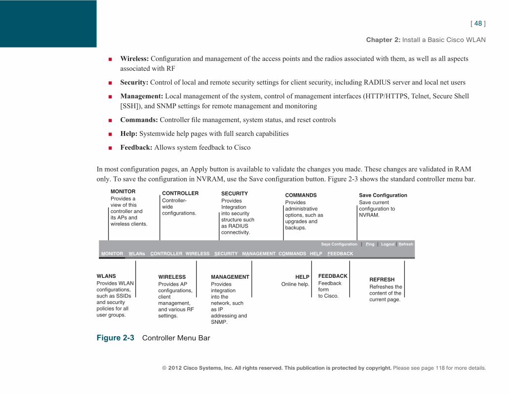
ptg7913109
[ 48 ]
© 2012 Cisco Systems, Inc. All rights reserved. This publication is protected by copyright. Please see page 118 for more details.
Chapter 2: Install a Basic Cisco WLAN
■ Wireless: Configuration and management of the access points and the radios associated with them, as well as all aspects associated with RF
■ Security: Control of local and remote security settings for client security, including RADIUS server and local net users
■ Management: Local management of the system, control of management interfaces (HTTP/HTTPS, Telnet, Secure Shell [SSH]), and SNMP settings for remote management and monitoring
■ Commands: Controller file management, system status, and reset controls
■ Help: Systemwide help pages with full search capabilities
■ Feedback: Allows system feedback to Cisco
In most configuration pages, an Apply button is available to validate the changes you made. These changes are validated in RAM only. To save the configuration in NVRAM, use the Save configuration button. Figure 2-3 shows the standard controller menu bar.
MONITORProvides aview of thiscontroller andits APs andwireless clients.
WLANS
MONITOR WLANs CONTROLLER WIRELESS SECURITY MANAGEMENT COMMANDS HELP FEEDBACK
Save Configuration Ping Logout Refresh
Provides WLANconfigurations,such as SSIDsand securitypolicies for alluser groups.
WIRELESSProvides APconfigurations,clientmanagement,and various RFsettings.
MANAGEMENTProvidesintegrationinto thenetwork, suchas IPaddressing andSNMP.
HELPOnline help.
FEEDBACKFeedbackformto Cisco.
REFRESHRefreshes thecontent of thecurrent page.
CONTROLLERController-wideconfigurations.
SECURITYProvidesIntegrationinto securitystructure suchas RADIUSconnectivity.
COMMANDSProvidesadministrativeoptions, such asupgrades andbackups.
Save ConfigurationSave currentconfiguration toNVRAM.
Figure 2-3 Controller Menu Bar
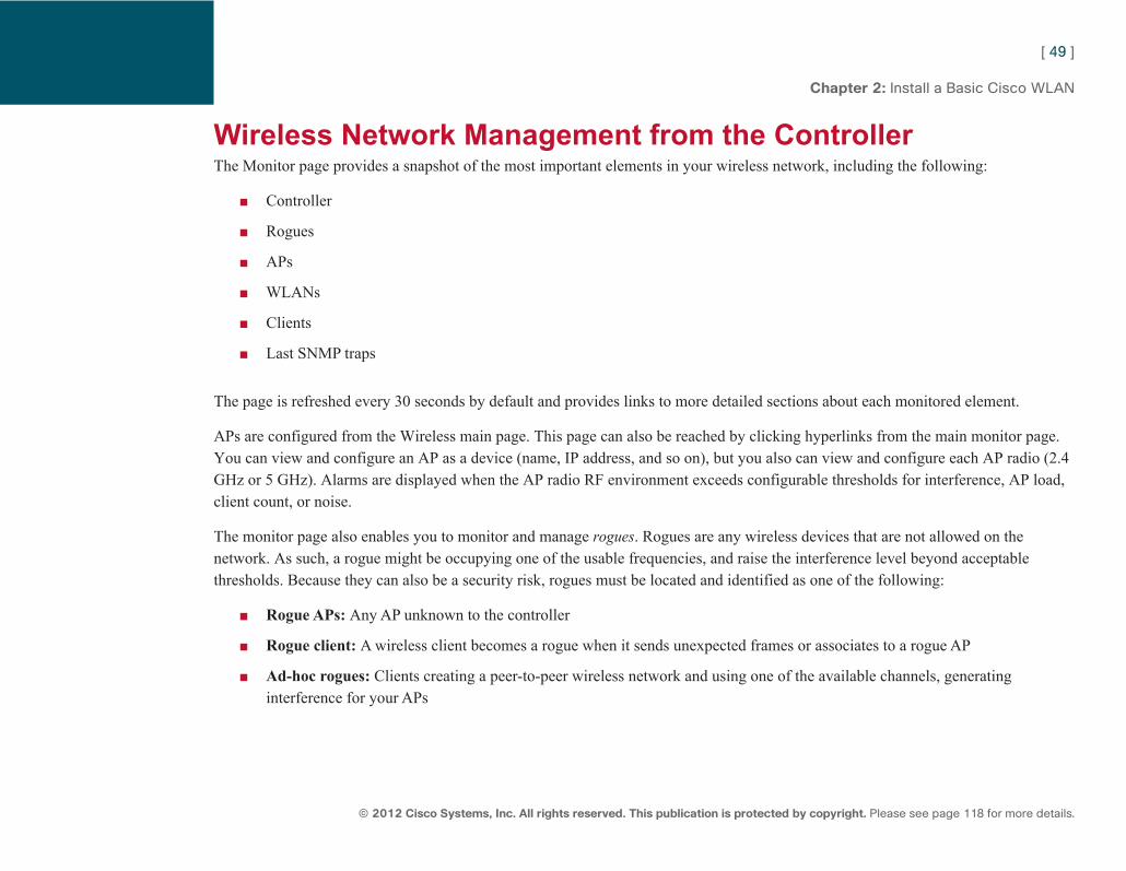
ptg7913109
[ 49 ]
© 2012 Cisco Systems, Inc. All rights reserved. This publication is protected by copyright. Please see page 118 for more details.
Chapter 2: Install a Basic Cisco WLAN
Wireless Network Management from the Controller The Monitor page provides a snapshot of the most important elements in your wireless network, including the following:
■ Controller
■ Rogues
■ APs
■ WLANs
■ Clients
■ Last SNMP traps
The page is refreshed every 30 seconds by default and provides links to more detailed sections about each monitored element.
APs are configured from the Wireless main page. This page can also be reached by clicking hyperlinks from the main monitor page. You can view and configure an AP as a device (name, IP address, and so on), but you also can view and configure each AP radio (2.4 GHz or 5 GHz). Alarms are displayed when the AP radio RF environment exceeds configurable thresholds for interference, AP load, client count, or noise.
The monitor page also enables you to monitor and manage rogues . Rogues are any wireless devices that are not allowed on the network. As such, a rogue might be occupying one of the usable frequencies, and raise the interference level beyond acceptable thresholds. Because they can also be a security risk, rogues must be located and identified as one of the following:
■ Rogue APs: Any AP unknown to the controller
■ Rogue client: A wireless client becomes a rogue when it sends unexpected frames or associates to a rogue AP
■ Ad-hoc rogues: Clients creating a peer-to-peer wireless network and using one of the available channels, generating interference for your APs
ptg7913109
[ 50 ]
© 2012 Cisco Systems, Inc. All rights reserved. This publication is protected by copyright. Please see page 118 for more details.
Chapter 2: Install a Basic Cisco WLAN
An AP detected as rogue might be an AP belonging to a neighboring network (in which case it should be identified as such and ignored) or an AP connected to the local network (detected by a rogue detector AP), in which case it must be located and removed. When a rogue is detected, its classification is Unclassified by default. You can analyze the rogue alert and further classify it manually, or set rules to auto-classify rogues matching parameters related to SSID name, RSSI value, or security parameters such as the following:
■ Friendly: A friendly rogue does not pose security threat. It can be of two subtypes:
■ Internal: The controller trusts this rogue access point because it belongs to your network. This option is available if the Class Type is set to Friendly.
■ External: The controller acknowledges the presence of this legitimate neighboring access point. This option is available if the Class Type is set to Friendly.
■ Malicious: The rogue poses a threat. This rogue can be contained. When you choose to contain a rogue, the controller uses one to four APs around the rogue to send deauthentication messages to the rogue clients (spoofing the rogue MAC address). Clients cannot maintain a connection to the rogue AP because they hear the deauthentication packets. Containing a rogue AP uses between 5 and 10 percent of the performance of the containing AP. This allows up to three rogues only to be concurrently contained by any single AP. Containing a rogue might have legal consequences. Do not attempt to contain valid access points operated by neighboring establishments, even if they appear as rogues on your system.
Each wireless client can also be monitored on the controller, for parameters such as MAC and IP addresses, RSSI/SNR, WLAN, authentication and encryption type, connected AP, and so on.
The controller can also be configured as a DHCP server to provide IP addresses to associating wireless clients (from Controller > Internal DHCP Server > DHCP Scope ). To use the controller for wireless clients’ IP assignments, the controller management interface must be set as the DHCP server IP address in each relevant dynamic interface. A scope can be defined for each interface subnet.
ptg7913109
[ 51 ]
© 2012 Cisco Systems, Inc. All rights reserved. This publication is protected by copyright. Please see page 118 for more details.
Chapter 2: Install a Basic Cisco WLAN
Clients that fail authentication several times (more than five consecutive 802.11 authentication failures, five consecutive 802.11 association failures, three consecutive 802.1x authentication failures, three consecutive web authentication failure, or attempt to use an IP address already assigned to another device) are excluded, by default, for 60 seconds. These exclusion parameters are defined from Security > Wireless Protection Policies > Client Exclusions Policies , and exclusion is activated for each WLAN from the WLAN Advanced tab. You can see these disabled clients from the Monitor page, and choose to reenable them before the expiration of the exclusion period or disable them permanently. Disabling a client permanently prevents the disabled MAC address from associating through any AP and any WLAN on the controller.
AP Controller Discovery After your controller is configured, it can start supporting CAPWAP APs. The booting CAPWAP AP starts by getting an IP address via DHCP (or statically if you configured the AP previously with a static IP address), then sends CAPWAP control messages (destination port UDP 5246) to discover as many controllers as possible and build a possible controller database. The AP uses the following methods to discover potential controllers:
■ Subnet Broadcast: The AP sends CAPWAP discovery messages to its subnet broadcast address.
■ DHCP Option 43: You can configure on the DHCP server a vendor-specific option (option 43) that can provide one or several controller management IP addresses to the AP getting an IP address from that DHCP server. This option is set as a hexadecimal string of the controller management IP addresses in an IOS DHCP scope, and the decimal (standard) form of the controller management IP addresses in a Windows DHCP scope.
■ DNS: If the AP learns about a DNS server, the AP tries to resolve the IP address of the host CISCO-CAPWAP-CONTROLLER. You can configure your DNS server to associate a controller management IP address to that host name.
■ Priming: On an AP, you can configure up to three controller IP addresses. This can be accomplished from the controller web interface (which supposes that the AP first joins a controller). From the AP CLI, you can also statically configure a controller IP address, which is useful when no other provisioning methods are available.
■ Flash: An AP will remember up to eight controllers it previously discovered.
ptg7913109
[ 52 ]
© 2012 Cisco Systems, Inc. All rights reserved. This publication is protected by copyright. Please see page 118 for more details.
Chapter 2: Install a Basic Cisco WLAN
The AP sends CAPWAP discovery messages to discover the controllers, and each controller responds with a CAPWAP discovery response message. After a list of potential controllers is built, the AP chooses to join one of the discovered controllers using the following order of preference:
1. Primary controller: The AP will associate first with its primary controller, assuming the AP has been primed. 2. Upon failing with the primary, the AP will try to register with its secondary and then its tertiary (if configured). 3. If no controller information is primed in the AP, or if the primary, secondary, and tertiary controllers cannot be reached,
the AP then looks for a master controller. The master controller is a feature you configure on a controller (from Controller > Advanced > Master Controller Mode ). Its purpose is precisely to offer a collection point for APs that cannot join their primary, secondary, or tertiary controller.
4. Finally, if the AP cannot discover a primed controller or a master controller, the AP will select the least loaded from all controllers that have responded to the discovery. Least loaded is relative to the controller license. In that sense, a 2106 controller with 4 APs is more loaded than a WiSM with 30 APs.
5. If no controller can be discovered, the AP reboots and restarts the discovery process.
When the discovery phase completes, the AP establishes a DTLS tunnel with the controller to join with one or two backup controllers. The AP first sends its certificate, then receives and verifies the controller certificate to form the tunnel. Within the DTLS tunnel, the AP sends a CAPWAP join request to the controller to join. The controller responds with a CAPWAP join response indicating success or failure.
In the join phase, the controller indicates its code release. If the AP firmware code release is different, the AP downloads the appropriate code from the controller. It ensures that you never need to upgrade the code of a CAPWAP AP manually: The AP will always download the right code from the controller it joins. Updating the AP code implies that the AP will reboot and restart the discovery process. For this reason, all your controllers should run the same code version.
When the join phase completes, the AP sends a configuration request to the controller. In the configuration response, the controller feeds the AP with all the parameters needed to offer wireless services (AP channel, power level, WLANs, and so on). When the configuration is complete, the AP can start offering wireless services to wireless clients.
ptg7913109
[ 53 ]
© 2012 Cisco Systems, Inc. All rights reserved. This publication is protected by copyright. Please see page 118 for more details.
Chapter 2: Install a Basic Cisco WLAN
At regular intervals, the AP and the controller exchange encrypted CAPWAP control messages to maintain and update the AP configuration. Notice that CAPWAP control messages are sent to the destination port UDP 5246, while client data encapsulated into CAPWAP is sent to the destination port UDP 5247.
Controller codes older than 5.2 used the ancestor of CAPWAP, called Lightweight AP Protocol (LWAPP). LWAPP was similar to CAPWAP, with a few functional differences:
■ LWAPP used UDP 12222 for encapsulated data and UDP 12223 for control traffic.
■ Data encryption was not possible with LWAPP.
■ The LWAPP AP would establish a tunnel only to the controller to join, not with one or two potential backup controllers.
■ CAPWAP uses a dynamic MTU discovery mechanism for the AP path to the controller. LWAPP used 1596 jumbo frames or 1500 standard Ethernet frames.
AP Failover After it’s associated, an AP sends a keepalive message to the controller every 30 seconds by default. You can configure faster heartbeats (1- to 10-second intervals). Whenever one heartbeat acknowledgement from the controller is missed, the AP resends the heartbeat five times at 1-second intervals. If no acknowledgement is received after the fifth retry, the AP declares the controller unreachable and searches for a new controller using the same preference order as in the initial discovery process.
Because no controller can take an AP beyond its license limit, you can configure a priority level for each AP (low, medium, high, or critical) to select which APs should join a backup controller in priority if the current controller fails. You also can enable or disable the AP fallback feature to decide whether the APs should automatically jump back to their controller if it comes back online.
You should always design your wireless network with redundancy in mind: AP redundancy, so that a neighboring AP can cover the area uncovered by a lost AP, and controller redundancy so that APs can always find a controller to join. Three controller redundancy models are possible, as shown in Figure 2-4 .
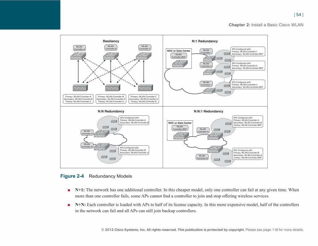
ptg7913109
[ 54 ]
© 2012 Cisco Systems, Inc. All rights reserved. This publication is protected by copyright. Please see page 118 for more details.
Chapter 2: Install a Basic Cisco WLAN
NOC or Data CenterWLAN-
Controller-BKP
APs Configured with:Primary: WLAN-Controller-BSecondary: WLAN-Controller-A
Resiliency
N:N Redundancy
WLAN-Controller-A
Primary: WLAN-Controller-ASecondary: WLAN-Controller-B
Tertiary: WLAN-Controller-C
Primary: WLAN-Controller-BSecondary: WLAN-Controller-C
Tertiary: WLAN-Controller-A
WLAN-Controller-B
WLAN-Controller-C
Primary: WLAN-Controller-CSecondary: WLAN-Controller-A
Tertiary: WLAN-Controller-B
APs Configured with:Primary: WLAN-Controller-ASecondary: WLAN-Controller-B
APs Configured with:Primary: WLAN-Controller-BSecondary: WLAN-Controller-ATertiary: WLAN-Controller-BKP
APs Configured with:Primary: WLAN Controller-ASecondary: WLAN Controller-BTertiary: WLAN Controller-BKP
N:N:1 Redundancy
N:1 Redundancy
WLAN-Controller-A
WLAN-Controller-1
WLAN-Controller-2
WLAN-Controller-n
WLAN-Controller-B
APs Configured with:Primary: WLAN-Controller-1Secondary: WLAN-Controller-BKP
APs Configured with:Primary: WLAN-Controller-2Secondary: WLAN-Controller-BKP
APs Configured with:Primary: WLAN-Controller-nSecondary: WLAN-Controller-BKP
NOC or Data CenterWLAN-
Controller-BKP
WLAN-Controller-A
WLAN-Controller-B
Figure 2-4 Redundancy Models
■ N+1: The network has one additional controller. In this cheaper model, only one controller can fail at any given time. When more than one controller fails, some APs cannot find a controller to join and stop offering wireless services.
■ N+N: Each controller is loaded with APs to half of its license capacity. In this more expensive model, half of the controllers in the network can fail and all APs can still join backup controllers.
ptg7913109
[ 55 ]
© 2012 Cisco Systems, Inc. All rights reserved. This publication is protected by copyright. Please see page 118 for more details.
Chapter 2: Install a Basic Cisco WLAN
■ N+N+1: In this intermediate and more common model, controllers are loaded to a certain (variable) percentage of their license limit (for example, 66%). An additional backup controller is available in the NOC. When one or several controllers fail, APs can join the NOC backup controller or the other controllers of the network. The number of controllers that can fail simultaneously depends on the controller’s AP load percentage.
AP Operational Modes A standard indoor AP that joins a controller operates by default in local mode, allowing for both client data services and monitoring of all channels simultaneously. The AP spends about 99% of the time on its main service channel, and jumps at regular intervals to other channels for short 60 ms periods to gather RF information (such as noise and interference or 802.11 signals). The AP scans one channel at a time, and scans all possible channels over a round trip time of 180 seconds by default (configurable). This information is used by RRM to determine the best power and channel combination for each AP.
APs can also be placed into monitor mode. In this mode, the APs do not allow for client connectivity but only monitor the IEEE 802.11 spectrum, scanning all channels in turn (you also can configure the system to scan a more limited list of channels), and spending about 1 second on each channel. This mode is used for troubleshooting and can also be used for site surveys. When using location tracking with a Cisco Mobility Service Engine, some additional APs operating in monitor mode can be added to the network to help increase the location accuracy, without interfering with the active APs already deployed. Monitor mode is passive: The AP scans and receives but does not send any information from its radios. Monitor mode APs can also be configured in two submodes of operation: Tracking Optimized Monitor Mode (TOMM), where the AP monitors only up to four configured channels for optimized monitoring and location of radio frequency identification (RFID) tags, and wIPS monitor mode (applicable only on Cisco 1130, 1140, 1240, and 1250 Series APs), where the AP scans all channels in turn, spending 250 ms on each channel to detect rogues.
APs can also be placed in sniffer mode, to passively capture traffic on one 2.4 GHz channel and one 5 GHz channel, and send the captured traffic to a remote station where an application such as AirMagnet, OmniPeek Pro v5.1, or Wireshark is used to display and analyze the captured frames. Sniffer mode is used for remote analysis of frames, troubleshooting, or baseline purposes. APs in sniffer mode do not provide wireless service and are limited to packet captures.
Note wIPS, used to optimize the detection of rogues, is a function available with APs in local mode, moni-tor mode, and H-REAP mode.
ptg7913109
[ 56 ]
© 2012 Cisco Systems, Inc. All rights reserved. This publication is protected by copyright. Please see page 118 for more details.
Chapter 2: Install a Basic Cisco WLAN
3500 and 3600 APs can also be placed in SE-Connect mode, also referred to as Spectrum Only Monitor Mode (SOMM). In this mode, the AP gathers information on the signal strength and duty cycle of all RF transmissions within bands utilized by the wireless network, and transmits the captured information to a remote station where the Cisco Spectrum Expert application is used to display and analyze the captured RF signals.
APs can also be placed in rogue detector mode. In this mode, the rogue detector AP is placed on a trunk port so it can monitor all wired-side connected VLANs, and the AP radios are turned off. The controllers send all rogue AP and client MAC address lists to the rogue detector. The rogue detector AP listens for Address Resolution Protocol (ARP) packets to determine the Layer 2 addresses of identified rogue clients or rogue APs sent by the controller. If a matching Layer 2 address is found, the AP generates an alarm to indicate that the rogue was not only detected in the wireless space, but also seen on the wired network.
APs can also be placed in bridge mode to be part of a mesh network (AP models 1040, 1130, 1140, 1240, 1250, 1260, 3500, and 3600). Some AP models are built specifically for outdoor mesh networks (1500 series) and are in mesh mode by default.
1040, 1130, 1140, 1240, 1250, 1260, 3500, or 3600 Series APs can also be placed in Hybrid Remote Edge Access Point (H-REAP) mode, also called Flexconnect. H-REAP is an alternative solution used to deploy a limited number of CAPWAP APs in remote offices without a local controller. The AP still needs to first connect to a remote controller to get its configuration. While in connected mode, the H-REAP can be configured to locally switch traffic from some of its WLANs and centrally switch (send to the controller) traffic from some other WLANs. The H-REAP uses a round trip time discovery mechanism to determine how long traffic takes to get to and from the controller. The authentication requests are forwarded by default to the controller, although the H-REAP can be configured to use local authentication even when in connected mode, using its local database (local EAP) or an external RADIUS server. When connection to the controller is lost, the H-REAP changes to standalone mode. In this mode, the AP performs the client authentication locally (or through an external RADIUS). Locally switched WLANs are still available, but centrally switched WLANs are shut down until connection to the controller is reestablished. The H-REAP mode is ideal for remote offices but has several limitations:
■ H REAP needs a minimum 500-byte maximum transmission unit (MTU) WAN link.
■ Roundtrip latency must not exceed 300 milliseconds (ms) for data and 100 ms for voice between the access point and the controller.
■ CAPWAP control packets must be prioritized over all other traffic.
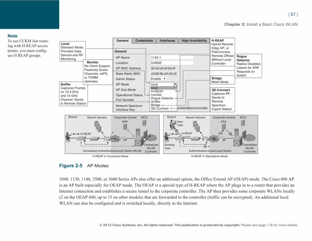
ptg7913109
[ 57 ]
© 2012 Cisco Systems, Inc. All rights reserved. This publication is protected by copyright. Please see page 118 for more details.
Chapter 2: Install a Basic Cisco WLAN
LocalGeneral
General
Credentials Interfaces High Availability
Standard Mode,Provides DataService and RFMonitoring
H-REAPHybrid RemoteEdge AP, orFlexConnect,Remote OfficesWithout LocalController
BridgeMesh Mode
SE-ConnectCaptures RF,Sends toRemoteSpectrumExpert Station
RogueDetectorRadios Disabled,Listens for ARPRequests onSwitch
MonitorNo Client Support,Passively ScansChannels, wIPS,or TOMMubmodes
AP Name
Location
AP MAC Address
Base Radio MAC
Admin Status
AP Mode
AP Sub Mode
Branch
H-REAP
Centralized Authentication/Local Switch WLAN
H-REAP in Connected Mode
Branch Servers Corporate Central WCSAAA
CentralizedWLAN
Controller
Operational Status
Port Number
Network SpectrumInterface Key
Enable
locallocalH-REAPmonitorRogue DetectorSnifferBridgeSE-Connect 9ADDCB92544C2A5B0
SnifferCaptures Frameson 12.4 GHzand 15 GHzChannel, Sendsto Remote Station
Branch
H-REAPdot1q
NewUser
ExistingUser
Authentication-Down/Local Switch
H-REAP in Standalone Mode
Branch Servers Corporate Central WCSAAA
CentralizedWLAN
Controller
c0:62:6b:d4:3d:c0
50:3d:e5:bf:0d:df
1142-1
IUWNE
OR
Figure 2-5 AP Modes
1040, 1130, 1140, 3500, or 3600 Series APs also offer an additional option, the Office Extend AP (OEAP) mode. The Cisco 600 AP is an AP built especially for OEAP mode. The OEAP is a special type of H-REAP where the AP plugs in to a router that provides an Internet connection and establishes a secure tunnel to the corporate controller. The AP then provides some corporate WLANs locally (2 on the OEAP 600, up to 15 on other models) that are forwarded to the controller (traffic can be encrypted). An additional local WLAN can also be configured and is switched locally, directly to the Internet.
Note To use CCKM fast roam-ing with H REAP access points, you must config-ure H REAP groups.
ptg7913109
[ 58 ]
© 2012 Cisco Systems, Inc. All rights reserved. This publication is protected by copyright. Please see page 118 for more details.
Chapter 2: Install a Basic Cisco WLAN
RRM and EDRRM
RRM Each AP monitors its channel and jumps occasionally to other channels to report about RF conditions on those channels. The controller uses this information for Radio Resource Management (RRM) and assigns the best channel and power level to each AP. Each AP also sends at regular intervals (60 seconds by default), at maximum power and all serviced radio channels an RRM neighbor message that is detected by neighboring APs and reported to their respective controller to help in this RRM mechanism. This message contains a hash that identifies the controller RF Group, which also helps identify rogue APs (APs that are unknown to the controller and do not have the right hash). RRM is made of three algorithms:
■ Transmit power control (TPC): This algorithm aims to reduce or increase the AP power. It is activated when an AP hears at least three neighboring APs. In that case, the controllers(s) work the AP power so that each AP hears its neighbor at a –70 dBm (configurable) RSSI average level. It is not activated for groups of APs smaller than four APs.
■ Coverage Hole Detection: This algorithm aims to increase the AP power. It is activated for each AP for which a configurable number of clients (by default, three3 clients or 25% of the clients, whichever threshold is reached first) have an RSSI fall below a configurable threshold (–80 dBm for data clients and –75 dBm for voice clients by default) for at least 60 seconds over the last 180 seconds, and cannot roam to another AP. In that case, the controller increases the affected AP power level to try to maintain the client connection.
■ Dynamic Channel Assignment (DCA): This algorithm aims to change the AP channel. It is activated when the controller calculations show that changing the AP channel would improve the AP client SNR. You can configure what the expected gain should be for the controller to change the AP channel.
All three algorithms are configured on a per-band level (2.4 GHz and 5 GHz), and you can take into account various parameters (AP load, neighboring APs, interferences) to fine tune their action. You can configure an RF Group on the controller, which is a subset of the Mobility Group. Controllers belonging to the same RF Group can work together to synchronize their action for TPC and DCA. Coverage Hole is local to each controller. You can disable the Coverage Hole algorithm on a per-WLAN basis if needed. When an RF Group is created, a RF Group leader is elected (you can force the election to designate a specific controller as the leader) to centralize the decisions. RRM decisions are taken every 600 seconds by default (configurable). RRM parameters are configured from Wireless > 802.11a/n [802.11b/g/n] > RRM.
ptg7913109
[ 59 ]
© 2012 Cisco Systems, Inc. All rights reserved. This publication is protected by copyright. Please see page 118 for more details.
Chapter 2: Install a Basic Cisco WLAN
CleanAir On controller code 7.0 and later, you can configure Event Driven RRM (EDRRM) from the Wireless > 802.11a/n [802.11b/g/n] > RRM > DCA page. Enabling EDRRM allows the controller to bypass the 600-second default interval for DCA and change an AP channel immediately if a disturbing non-802.11 interference is detected on the AP channel. You can set the sensitivity threshold to High (60), Medium (50), or Low (35). This threshold refers to the Air Quality index. CleanAir-capable APs (3500 and 3600 Series APs, with their CleanAir capable chipset) can detect and identify non-802.11 interferences and report them to the controller. These APs can report interferers when in local mode and monitor mode. Notice that the AP cannot report to the controller when in Spectrum Only Monitor Mode (SOMM). The controller uses the reported information to list non-802.11 interferers along with their zone of impact and severity and establish an Air Quality Index (AQI) from 100 (perfect) to 0 (network unusable). Notice that the logic of the global AQ index (higher is better) is exactly the opposite of the logic of the individual interferer severity index (higher is more severe, and therefore worse). The severity index is calculated individually by each detecting AP based on the power (signal strength), duty cycle (how often the device uses the air per second), and detected type of interferer. The louder an interferer device, the higher the duty cycle will mean a higher severity index for the reporting AP. The severity index is calculated for a specific device, without regard to what channels are being affected. The AQI is global to the entire system. Samples are taken every second by each AP; AQI is calculated every 15 seconds and summarized into 30-second intervals, which are then reported up to the controller every 15 minutes (by default). The exception is when an administrator is actively monitoring an AP radio interface from Cisco WCS or WLC, then the AP is automatically instructed to switch into a rapid update mode, which changes the default reporting period to 30 seconds to provide more real-time information.
Because non-802.11 devices often do not have a MAC address, each detecting AP generates for each interferer a pseudo-MAC address (PMAC). This PMAC is mentioned in the AP Interference Detection Report (IDR). The controller consolidates all the reports, recognizes devices that are reported by several APs, and affects a global PMAC to each of them.
You can enable or disable CleanAir globally for each spectrum from Wireless > 802.11a/n [802.11b/g/n] > CleanAir . You also can enable or disable CleanAir specifically for each CleanAir-capable radio from Access Points > Radios > 802.11a/n [802/11 b/g/n] . From the CleanAir global page, you can enable which interferers to report, such as the following:
■ Bluetooth Paging Inquiry: Bluetooth in discovery mode
■ Bluetooth Sco Acl: A Bluetooth active link
ptg7913109
[ 60 ]
© 2012 Cisco Systems, Inc. All rights reserved. This publication is protected by copyright. Please see page 118 for more details.
Chapter 2: Install a Basic Cisco WLAN
■ Generic DECT: A digital enhanced cordless communication (DECT)-compatible phone
■ Generic TDD: Time division duplex (TDD) transmitter
■ Generic Waveform
■ Jammer
■ Microwave: Oven
■ Canopy: Device
■ Radar, Spectrum 802.11 FH: Frequency-hopping device
■ Spectrum 802.11 inverted: A device using spectrally inverted Wi-Fi signals
■ Spectrum 802.11 non std channel: A device using nonstandard Wi-Fi channels
■ Spectrum 802.11 SuperG: An 802.11 SuperAG device
■ Spectrum 802.15.4: ZigBee or WirelessHart device
■ Video Camera: An analog, non-802.11 video camera
■ WiMAX Fixed: Device
■ WiMAX Mobile: Device
■ Xbox
You also can decide on conditions for non-802.11 interferer-related alarms (interferer type and severity thresholds needed to trigger an alarm).
ptg7913109
[ 61 ]
© 2012 Cisco Systems, Inc. All rights reserved. This publication is protected by copyright. Please see page 118 for more details.
Chapter 2: Install a Basic Cisco WLAN
Roaming A key component of efficiency in wireless networks deployment is roaming management. Roaming is the action for a wireless client to move its association from an AP to another AP while actively transmitting or receiving data. Roaming is common for VoWLAN deployments, while data deployments are more commonly nomadic (users stop using the wireless device while moving, and connection may be temporarily lost while the user moves to another location without impacting the user experience).
When a wireless client associates and authenticates to an access point, the access point’s controller places an entry for that client in its client database, which contains the client MAC and IP addresses, QoS parameters, the WLAN and the associated access point. In a controller-based solution, three roaming scenarios are considered:
■ Intra-controller roaming: The wireless user moves from one AP to another AP connected to the same controller. In this case, the controller’s only action is to change the associated AP in the client database entry. The process is transparent to the client and takes less than 10 ms.
■ Layer 2 intercontroller roaming: The wireless user moves from one AP to another AP connected to another controller in the same subnet (as the first controller). When the client tries to join the new AP, both controllers exchange the client details (database entry and credentials). The process takes less than 20 ms and is usually seamless for the client.
■ Layer 3 intercontroller roaming: The wireless user moves from one AP to another AP connected to another controller in a different subnet. When the client tries to join the new AP, both controllers also exchange the client details (database entry and credentials). The process takes less than 30 ms and is usually seamless for the client. This scenario can be more complicated because the roaming mechanism can be local-to-local if both controllers support the same WLAN-to-VLAN mapping for the client WLAN. In this case, the client entry is moved completely to the new controller. The roaming can also be local-to-foreign if both controllers’ WLAN-to-VLAN mapping for the client WLAN is different. In that case, the new controller (called the foreign controller) encapsulates the client traffic into an Ethernet over IP (EoIP) packet and forwards it to the old controller, called the anchor . Return traffic is sent to the anchor controller, which forwards it via EoIP to the foreign controller and the client. For the wired infrastructure, the client traffic is still entirely handled by, and goes through, the anchor controller. When idle, the roamed client may renew its connection and then associate locally to the foreign controller.
ptg7913109
[ 62 ]
© 2012 Cisco Systems, Inc. All rights reserved. This publication is protected by copyright. Please see page 118 for more details.
Chapter 2: Install a Basic Cisco WLAN
You can also configure some WLANs with a static mobility anchor. In that case, the client traffic is always sent via an EoIP tunnel to the anchor controller, regardless of the connecting AP. This is useful for guest WLANs when the anchor controller is in the DMZ.
When clients with a static IP associate to a controller, the controller can query the other controllers to find a controller supporting the client subnet and use that controller as an anchor, thus allowing static IP client association and roaming even through controllers not supporting the client subnet directly.
The anchor is configured for each WLAN. An anchor controller must first be added to the local controller mobility list before being set as an anchor. Anchoring must be set on both sides (the WLAN on the foreign controller must point to the anchor controller, and the WLAN on the anchor controller must also point to the anchor itself, so that the anchor recognizes that it terminates the tunnel). The WLAN configuration must be identical on the foreign controller and on the anchor controller for the tunnel and the anchor to form properly (the only allowed differences are the associated dynamic interface, RADIUS server and Layer 2 pre-shared key when applicable). The client will receive all its configuration parameters (DHCP IP address and security configuration) from the anchor controller, but the foreign controller must ensure that the anchor controller WLAN is the same as its own, to accept the handover to the anchor. Make sure that foreign to anchor communication is possible for mobility traffic. You can test this communication with the eping command (which tests data packets sent to the mobility port UDP 16666) and the mping command (which tests Ethernet over IP encapsulation over the tunnel). Figure 2-6 summarizes the intercontroller roaming principles.
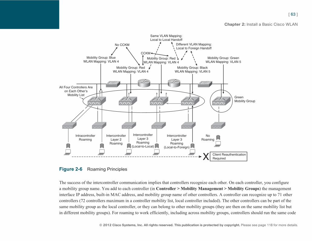
ptg7913109
[ 63 ]
© 2012 Cisco Systems, Inc. All rights reserved. This publication is protected by copyright. Please see page 118 for more details.
Chapter 2: Install a Basic Cisco WLAN
All Four Controllers Areon Each Other’s
Mobility List
IntracontrollerRoaming
NoRoaming
Client ReauthenticationRequired
IntercontrollerLayer 2
Roaming
IntercontrollerLayer 3
Roaming(Local-to-Local)
IntercontrollerLayer 3
Roaming(Local-to-Foreign)
Mobility Group: BlueWLAN Mapping: VLAN 4
Mobility Group: GreenWLAN Mapping: VLAN 5
GreenMobility Group
Mobility Group: BlackWLAN Mapping: VLAN 5
Mobility Group: RedWLAN Mapping: VLAN 4
No CCKM
CCKM
Same VLAN Mapping:Local to Local Handoff
Different VLAN Mapping:Local to Foreign Handoff
Mobility Group: RedWLAN Mapping: VLAN 4
Figure 2-6 Roaming Principles
The success of the intercontroller communication implies that controllers recognize each other. On each controller, you configure a mobility group name. You add to each controller (in Controller > Mobility Management > Mobility Groups ) the management interface IP address, built-in MAC address, and mobility group name of other controllers. A controller can recognize up to 71 other controllers (72 controllers maximum in a controller mobility list, local controller included). The other controllers can be part of the same mobility group as the local controller, or they can belong to other mobility groups (they are then on the same mobility list but in different mobility groups). For roaming to work efficiently, including across mobility groups, controllers should run the same code
ptg7913109
[ 64 ]
© 2012 Cisco Systems, Inc. All rights reserved. This publication is protected by copyright. Please see page 118 for more details.
Chapter 2: Install a Basic Cisco WLAN
version and use the same virtual gateway IP address (thus appearing as a single cluster). The caveat is that Cisco Centralized Key Management (CKM) and Proactive Key Caching (PKC) do not work across mobility groups. If you roam to a controller you know but that has another mobility group value, and if you use 802.1X with CCKM or WPA2, your key will not get transmitted to the other controller and you will have to reauthenticate to get a new key. Intercontroller roaming also does not work (with any security mechanism) when controllers do not know each other: In that case, the roaming client must reauthenticate completely.
Autonomous AP Management and Migration Autonomous APs use a firmware that enables them to offer wireless service without a controller. Each autonomous AP must be configured independently. You can configure and manage a Cisco standalone AP using the CLI via a console port or Telnet/SSH. In all cases, default credentials are none/Cisco (no username is required, and any username is valid for SSH; default password is Cisco). It is often easier to use the web browser interface of the AP to apply this configuration. When you connect a standalone AP with a default configuration to your LAN, the AP makes several attempts to obtain an IP address from the DHCP server. If it does not receive an address, it sends requests indefinitely. You also can configure a static IP address (via the console, for example). You can then open a web browser session to the AP IP address to access the web interface. Notice that the IP address is assigned to the AP bridge interface (BVI1), which is a virtual interface bearing an IP address shared by all interfaces (radios and Ethernet).
Basic configuration can be conducted through the Express Setup web page (where the AP IP address, name, and SNMP communities are set) and the Express Security page (where a WLAN can be configured). These pages allow for simple AP configuration but are limited in features:
■ You cannot edit SSIDs (you can delete SSIDs and re-create them).
■ You cannot assign SSIDs to specific radio interfaces (the SSIDs that you create are enabled on all radio interfaces).
■ You cannot configure multiple authentication servers when using 802.1X.
■ You cannot configure multiple WEP keys.
■ You cannot assign an SSID to a VLAN that is already configured on the AP.
■ You cannot configure combinations of authentication types on the same SSID (such as MAC address authentication and EAP authentication).
ptg7913109
[ 65 ]
© 2012 Cisco Systems, Inc. All rights reserved. This publication is protected by copyright. Please see page 118 for more details.
Chapter 2: Install a Basic Cisco WLAN
For more complex configurations, you must use a combination of specific submenus on the AP web interface.
Autonomous APs are adapted to small networks. A task commonly assigned to CCNA Wireless professionals is migrating autonomous APs to CAPWAP by pushing a minimal CAPWAP firmware image to the AP. This minimal CAPWAP firmware image is platform dependent and can be downloaded from www.cisco.com (k9w8 in the image name usually identifies the CAPWAP code for an AP). The conversion can be done several ways:
■ You can use an IOS-to-CAPWAP upgrade tool running on Windows. The autonomous AP must be running Cisco IOS Software version 12.3(7) JA or higher, and the WLC should be running version 3.1 or later. A Windows PC with the Lightweight upgrade tool is also required. In the IOS-to-CAPWAP upgrade tool, you would input a text file (containing each AP to convert IP address, and telnet and privilege mode credentials) and would provide the information needed for the conversion process (controller details, TFTP server IP address, and CAPWAP firmware filename). The tool would then connect to each AP and run the conversion routine.
■ You can convert the AP from the Cisco WCS interface. You would first add the autonomous AP to the WCS (from Configure > Access Points > Add Autonomous AP ), providing the AP IP address, telnet and enable credentials, and an RW SNMP community name configured on the AP. After the autonomous AP is added to WCS, you can navigate to Configure > Migration Templates and create a template to convert the autonomous AP to CAPWAP.
■ You can convert the AP directly from the CLI with the command archive download software ftp|tftp://<address and name of the minimal CAPWAP file to use>.
After the AP is updated, it gains CAPWAP functionalities but loses the capability to work in autonomous mode. APs manufactured before July 2005 will gain a self-signed certificate, while those manufactured after July 2005 contain a manufacturing installed certificate (MIC).
You can revert the AP back from CAPWAP to Cisco IOS by downloading a Cisco IOS firmware image for this AP from Cisco.com and position this image in a TFTP server (k9w7 in the image name usually identifies the IOS version of the AP code). You then must associate the CAPWAP AP to the controller, and run, from the controller CLI (migration is not available from the controller web interface), the command config ap tftp-downgrade tftp-server-ip-address filename access-point-name.
ptg7913109
[ 66 ]
© 2012 Cisco Systems, Inc. All rights reserved. This publication is protected by copyright. Please see page 118 for more details.
CCNA Wireless (640-722 IUWNE) Quick Reference
Chapter 3 Install Wireless Clients Clients are an essential part of wireless networks. They require a specific section in CCNA Wireless because not all clients are the same. Wireless clients are differentiated by three types of characteristics:
■ Wi-Fi client adapter: Most devices produced today come with built-in wireless adapters. Older devices can be outfitted with an external wireless networking card. Different cards might have different physical characteristics and capabilities.
■ Wireless client software: Client software, such as the Intel ProSet, AirPort Extreme for MAC, Windows AutoConfig Service, Apple iOS, and Google Android, can be configured for the client to associate with an AP. Different software applications can have different feature sets and different supports for the underlying physical card capabilities.
■ Client security settings: There are several possible security configurations to achieve wireless security. Some clients support only some security types, thus limiting the type of wireless network you can join.
Most clients enable you to associate to a detected network (broadcasted SSID) or configure a specific profile. In all cases, you must configure the network name (SSID), the operating mode (ad-hoc or infrastructure), and some security settings (that will be different depending on whether the SSID uses Pre-Shared Key Security or Enterprise [EAP/802.1x] security). The way each of these three items is configured (sequence, menu names, configuration possibilities) varies from one client to the next.
ptg7913109
[ 67 ]
© 2012 Cisco Systems, Inc. All rights reserved. This publication is protected by copyright. Please see page 118 for more details.
Chapter 3: Install Wireless Clients
Intel ProSet Because Intel is a major wireless chipset vendor, it is common to see wireless clients use the Intel ProSet utility to configure an Intel wireless card. The client features are integrated to Windows with Windows 7, thus adding new functionalities to the Windows wireless utility instead of offering a different program interface. For example, Windows natively does not support EAP-FAST or LEAP (Mac Export Extreme natively supports these security mechanisms). Using Intel ProSet adds support for these mechanisms on a Windows machine. In older Windows versions (Vista and older), Intel ProSet can be installed to replace the Windows utility and offer a specific interface to configure the Intel wireless card.
Once installed, the utility appears as an icon representing a wave at the right of the taskbar. Right-clicking that icon offers the option to disable the wireless card, connect to an already configured wireless network profile, or open the Intel ProSet utility.
Opening the utility displays the list of detected networks. You can connect to a network by double-clicking the network name in the list (or clicking the name then clicking Connect) and answering the questions relevant to the SSID security credentials when applicable.
You can also click Profiles to manage existing profiles (modify or delete) or create new profiles. When creating a new profile, you first must enter the SSID name, the operating mode (ad-hoc or infrastructure), and then the security type (personal, using open or preshared key authentication, or enterprise, using 802.1X/EAP authentication). You then configure the security details based on the security type you chose. Figure 3-1 shows the Intel ProSet main options.
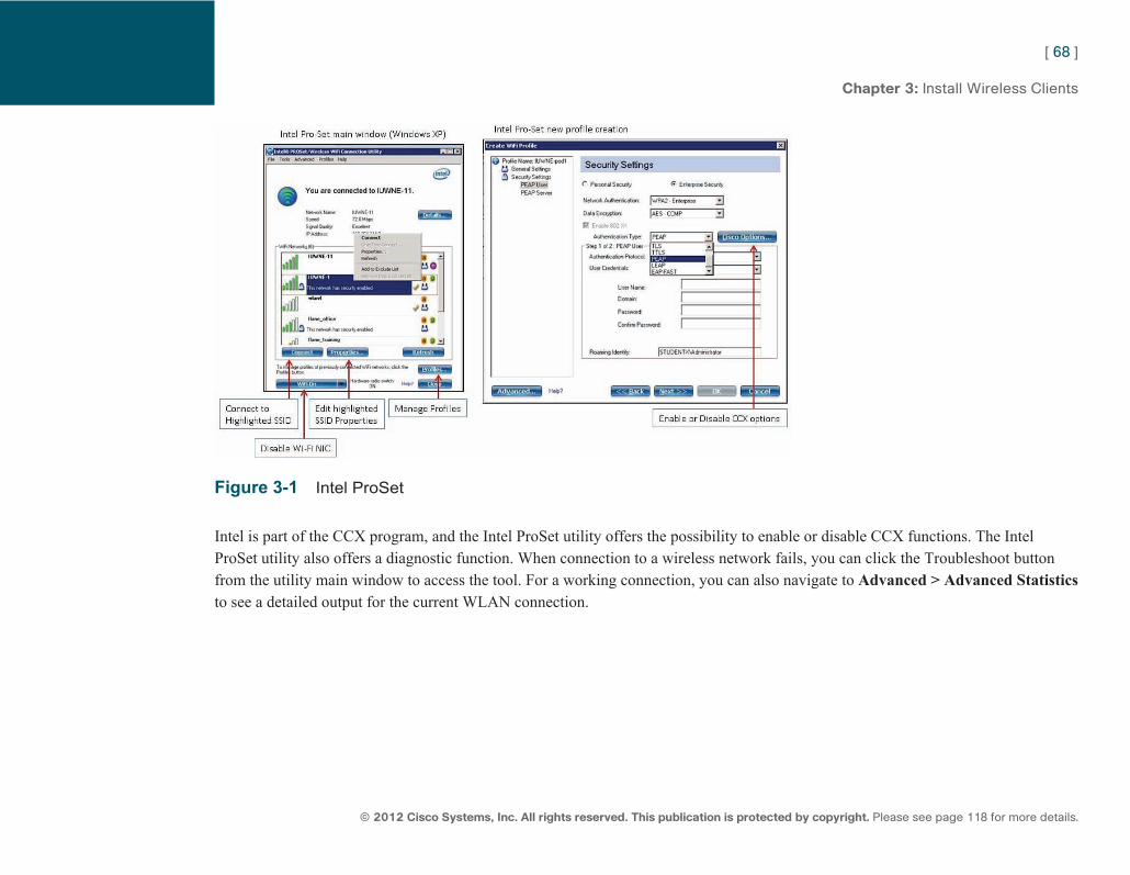
ptg7913109
[ 68 ]
© 2012 Cisco Systems, Inc. All rights reserved. This publication is protected by copyright. Please see page 118 for more details.
Chapter 3: Install Wireless Clients
Figure 3-1 Intel ProSet
Intel is part of the CCX program, and the Intel ProSet utility offers the possibility to enable or disable CCX functions. The Intel ProSet utility also offers a diagnostic function. When connection to a wireless network fails, you can click the Troubleshoot button from the utility main window to access the tool. For a working connection, you can also navigate to Advanced > Advanced Statistics to see a detailed output for the current WLAN connection.
ptg7913109
[ 69 ]
© 2012 Cisco Systems, Inc. All rights reserved. This publication is protected by copyright. Please see page 118 for more details.
Chapter 3: Install Wireless Clients
Mac AirPort Extreme AirPort (for 802.11b) and AirPort Extreme (for 802.11b/g/n or 802.11a/b/g/n) are WLAN configuration utilities from Apple. The utility allows the creation of network profiles, association to detected networks, and advanced configuration and troubleshooting. The wireless card can be disabled or enabled from the utility main window. The utility automatically attempts to join detected networks (trying the preferred profiles first) and offers to connect to the available networks if no preferred SSID is in range. On the left of the screen, the available network connections (wired and wireless) are displayed, and the connection status of the WLAN adapter can be displayed, along with the signal level.
You can connect to a detected network by clicking the network name, and then clicking the join button and answering the questions relevant to the SSID security credentials when applicable. You also can create a new profile by clicking the + button instead of clicking a detected network name. You can then choose the Create Network option to create a new ad-hoc network, or Join Other Network to create a new infrastructure profile. After you enter the SSID name, you can choose the security type, and then enter the parameters relevant to the security type you chose.
From the AirPort main menu, click Advanced to display advanced parameters for the network connections. A new window appears, with seven tabs (AirPort, TCP/IP, DNS, WINS, AppleTalk, 802.1X, and Proxies). Among these tabs, the AirPort tab lists all the configured profiles. Clicking on one of them enables you to edit its configuration parameters. It is also possible to change the connection order and select other general parameters. The 802.1X tab enables you to select each configured wireless profiles and edit its 802.1X/EAP security settings when applicable.
When the wireless card is enabled, an icon is present in the desktop menu bar. Click the icon to see basic information about the connection (SSID name and connection options), or press the Option key and click the icon to see detailed information about the connection (SSID name, capabilities [802.11a/b/g or n], BSSID MAC address, channel, RSSI, security, and data rate/MCS). Figure 3-2 shows Mac AirPort Extreme.
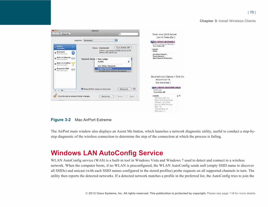
ptg7913109
[ 70 ]
© 2012 Cisco Systems, Inc. All rights reserved. This publication is protected by copyright. Please see page 118 for more details.
Chapter 3: Install Wireless Clients
Figure 3-2 Mac AirPort Extreme
The AirPort main window also displays an Assist Me button, which launches a network diagnostic utility, useful to conduct a step-by-step diagnostic of the wireless connection to determine the step of the connection at which the process is failing.
Windows LAN AutoConfig Service WLAN AutoConfig service (WAS) is a built-in tool in Windows Vista and Windows 7 used to detect and connect to a wireless network. When the computer boots, if no WLAN is preconfigured, the WLAN AutoConfig sends null (empty SSID name to discover all SSIDs) and unicast (with each SSID names configured in the stored profiles) probe requests on all supported channels in turn. The utility then reports the detected networks. If a detected network matches a profile in the preferred list, the AutoConfig tries to join the
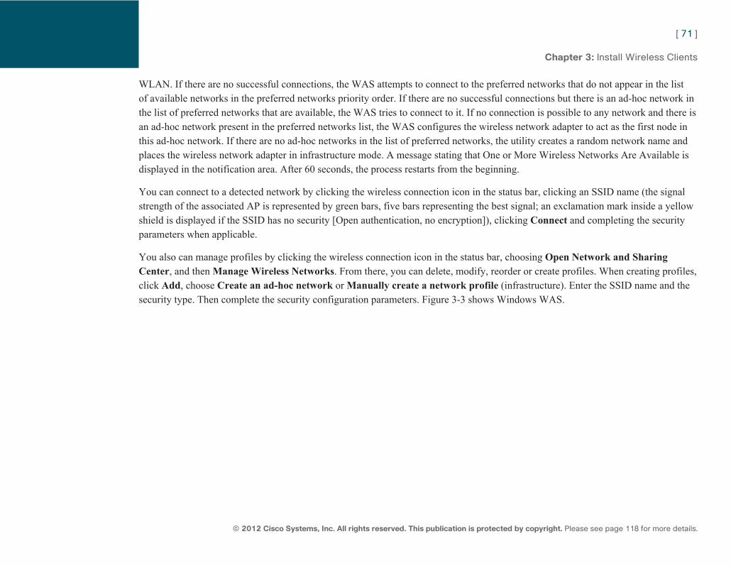
ptg7913109
[ 71 ]
© 2012 Cisco Systems, Inc. All rights reserved. This publication is protected by copyright. Please see page 118 for more details.
Chapter 3: Install Wireless Clients
WLAN. If there are no successful connections, the WAS attempts to connect to the preferred networks that do not appear in the list of available networks in the preferred networks priority order. If there are no successful connections but there is an ad-hoc network in the list of preferred networks that are available, the WAS tries to connect to it. If no connection is possible to any network and there is an ad-hoc network present in the preferred networks list, the WAS configures the wireless network adapter to act as the first node in this ad-hoc network. If there are no ad-hoc networks in the list of preferred networks, the utility creates a random network name and places the wireless network adapter in infrastructure mode. A message stating that One or More Wireless Networks Are Available is displayed in the notification area. After 60 seconds, the process restarts from the beginning.
You can connect to a detected network by clicking the wireless connection icon in the status bar, clicking an SSID name (the signal strength of the associated AP is represented by green bars, five bars representing the best signal; an exclamation mark inside a yellow shield is displayed if the SSID has no security [Open authentication, no encryption]), clicking Connect and completing the security parameters when applicable.
You also can manage profiles by clicking the wireless connection icon in the status bar, choosing Open Network and Sharing Center , and then Manage Wireless Networks . From there, you can delete, modify, reorder or create profiles. When creating profiles, click Add , choose Create an ad-hoc network or Manually create a network profile (infrastructure). Enter the SSID name and the security type. Then complete the security configuration parameters. Figure 3-3 shows Windows WAS.
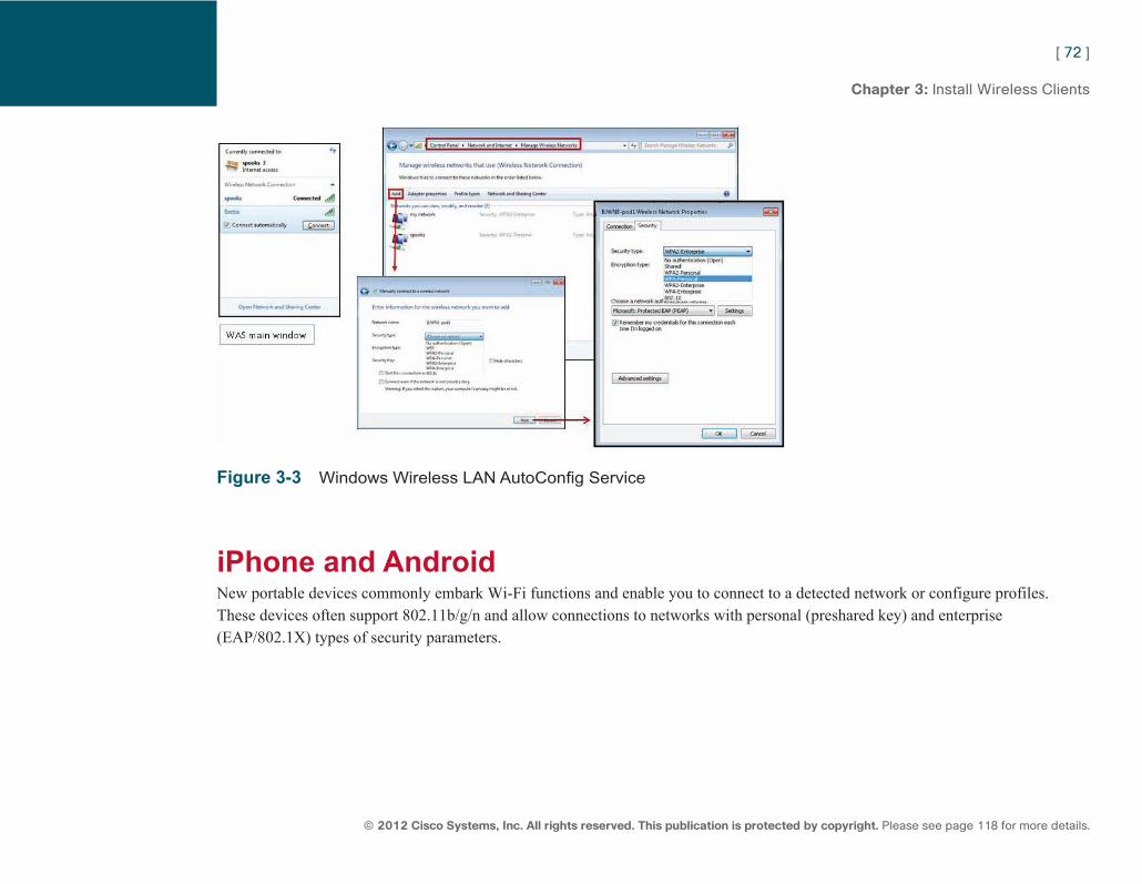
ptg7913109
[ 72 ]
© 2012 Cisco Systems, Inc. All rights reserved. This publication is protected by copyright. Please see page 118 for more details.
Chapter 3: Install Wireless Clients
Figure 3-3 Windows Wireless LAN AutoConfig Service
iPhone and Android New portable devices commonly embark Wi-Fi functions and enable you to connect to a detected network or configure profiles. These devices often support 802.11b/g/n and allow connections to networks with personal (preshared key) and enterprise (EAP/802.1X) types of security parameters.
ptg7913109
[ 73 ]
© 2012 Cisco Systems, Inc. All rights reserved. This publication is protected by copyright. Please see page 118 for more details.
Chapter 3: Install Wireless Clients
Cisco AnyConnect Mobility Client The Cisco AnyConnect Secure Mobility Client is a multifunctional and modular security client. It was built to enable you to use the same interface across various hardware and software platforms (operating systems) to manage and secure your connections to the network. It contains several modules:
■ VPN Module
■ Diagnostic Reporting Tool (DART, to analyze and troubleshoot connections)
■ Network Access Module (provided as part of the Network Access Manager to manage user and device identity over wired and wireless deployments)
■ Posture Module (to identify the operating system, antivirus, anti-spyware, and firewall installed on the host)
■ Telemetry (used with the Cisco IronPort Web Security Appliance to identify the source of malwares)
■ Web Security Module (cloud-based real-time web protection and policy enforcement)
You can just install the modules you need, then add or remove modules as the security needs change.
The main components used in IUWNE are the Cisco AnyConnect Mobility Client itself, associated with the Network Access Module (NAM) used to manage existing profiles. AnyConnect Network Access Manager is licensed without charge for use with Cisco wireless access points, wireless LAN controllers, switches, and RADIUS servers, but a current SmartNet contract is required on the related Cisco equipment.
The Cisco AnyConnect client and the NAM module can be deployed by asking users to open a web browser session to an ASA running ASDM GUI version 6.4(0)104 or later and download the required modules, or by installing the modules manually on each client. Note that the AnyConnect VPN installer must be installed first, before AnyConnect client and NAM, even if you do not need VPN. Without the VPN component, the other modules cannot work properly.
Once installed, the AnyConnect client displays an icon in the status bar. Click the icon to open the utility and connect to one of the detected wireless networks. You also can click Advanced to open the NAM front end. You can then manage profiles (create, delete, reorder). The network administrator can restrict the types of networks that the end user can manipulate on the NAM. For
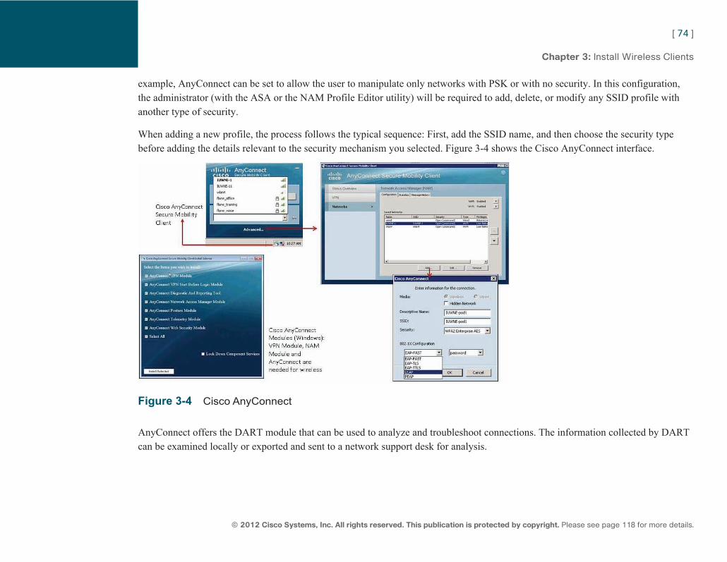
ptg7913109
[ 74 ]
© 2012 Cisco Systems, Inc. All rights reserved. This publication is protected by copyright. Please see page 118 for more details.
Chapter 3: Install Wireless Clients
example, AnyConnect can be set to allow the user to manipulate only networks with PSK or with no security. In this configuration, the administrator (with the ASA or the NAM Profile Editor utility) will be required to add, delete, or modify any SSID profile with another type of security.
When adding a new profile, the process follows the typical sequence: First, add the SSID name, and then choose the security type before adding the details relevant to the security mechanism you selected. Figure 3-4 shows the Cisco AnyConnect interface.
Figure 3-4 Cisco AnyConnect
AnyConnect offers the DART module that can be used to analyze and troubleshoot connections. The information collected by DART can be examined locally or exported and sent to a network support desk for analysis.
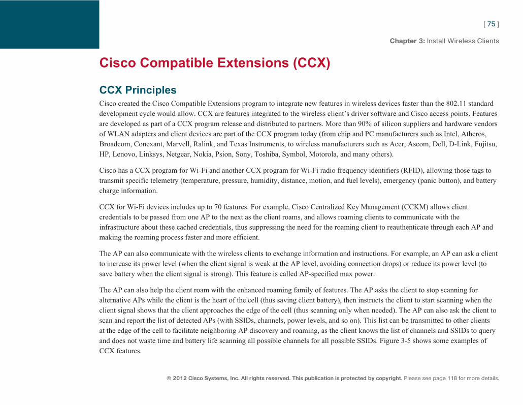
ptg7913109
[ 75 ]
© 2012 Cisco Systems, Inc. All rights reserved. This publication is protected by copyright. Please see page 118 for more details.
Chapter 3: Install Wireless Clients
Cisco Compatible Extensions (CCX)
CCX Principles Cisco created the Cisco Compatible Extensions program to integrate new features in wireless devices faster than the 802.11 standard development cycle would allow. CCX are features integrated to the wireless client’s driver software and Cisco access points. Features are developed as part of a CCX program release and distributed to partners. More than 90% of silicon suppliers and hardware vendors of WLAN adapters and client devices are part of the CCX program today (from chip and PC manufacturers such as Intel, Atheros, Broadcom, Conexant, Marvell, Ralink, and Texas Instruments, to wireless manufacturers such as Acer, Ascom, Dell, D-Link, Fujitsu, HP, Lenovo, Linksys, Netgear, Nokia, Psion, Sony, Toshiba, Symbol, Motorola, and many others).
Cisco has a CCX program for Wi-Fi and another CCX program for Wi-Fi radio frequency identifiers (RFID), allowing those tags to transmit specific telemetry (temperature, pressure, humidity, distance, motion, and fuel levels), emergency (panic button), and battery charge information.
CCX for Wi-Fi devices includes up to 70 features. For example, Cisco Centralized Key Management (CCKM) allows client credentials to be passed from one AP to the next as the client roams, and allows roaming clients to communicate with the infrastructure about these cached credentials, thus suppressing the need for the roaming client to reauthenticate through each AP and making the roaming process faster and more efficient.
The AP can also communicate with the wireless clients to exchange information and instructions. For example, an AP can ask a client to increase its power level (when the client signal is weak at the AP level, avoiding connection drops) or reduce its power level (to save battery when the client signal is strong). This feature is called AP-specified max power.
The AP can also help the client roam with the enhanced roaming family of features. The AP asks the client to stop scanning for alternative APs while the client is the heart of the cell (thus saving client battery), then instructs the client to start scanning when the client signal shows that the client approaches the edge of the cell (thus scanning only when needed). The AP can also ask the client to scan and report the list of detected APs (with SSIDs, channels, power levels, and so on). This list can be transmitted to other clients at the edge of the cell to facilitate neighboring AP discovery and roaming, as the client knows the list of channels and SSIDs to query and does not waste time and battery life scanning all possible channels for all possible SSIDs. Figure 3-5 shows some examples of CCX features.
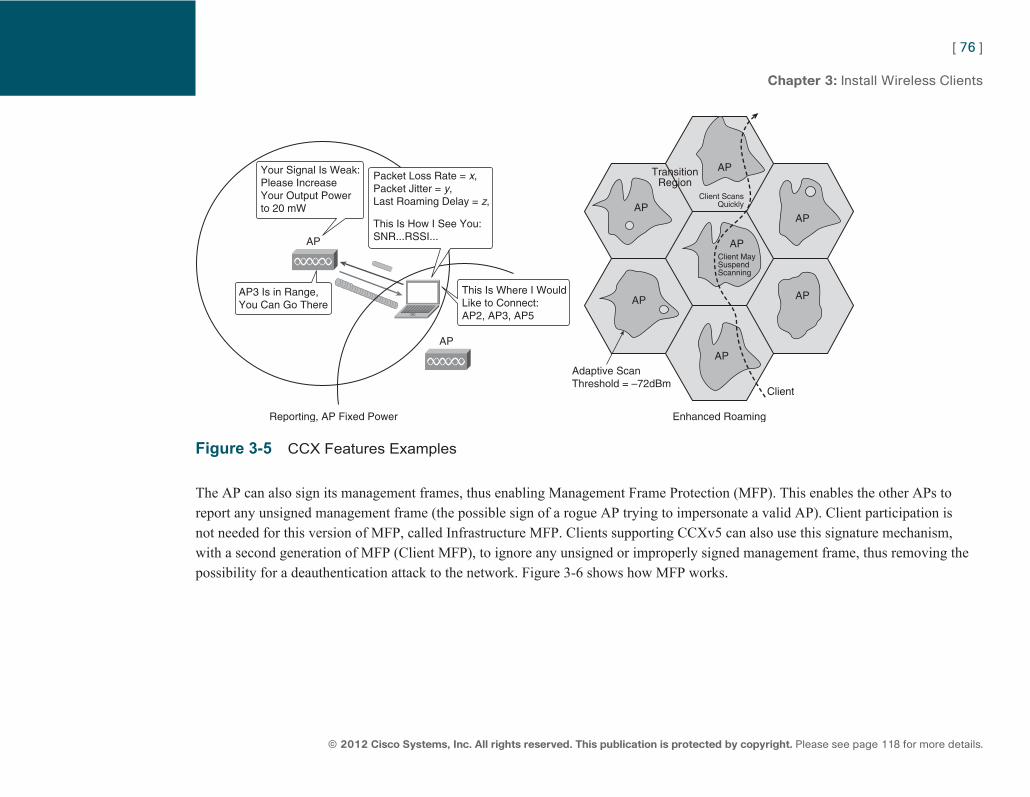
ptg7913109
[ 76 ]
© 2012 Cisco Systems, Inc. All rights reserved. This publication is protected by copyright. Please see page 118 for more details.
Chapter 3: Install Wireless Clients
AP
AP
AP
Client
Adaptive ScanThreshold = –72dBm
TransitionRegion
AP
AP
AP
AP
Client MaySuspendScanning
Client ScansQuickly
AP
AP
Your Signal Is Weak:Please IncreaseYour Output Powerto 20 mW
Packet Loss Rate = x,Packet Jitter = y,Last Roaming Delay = z,
This Is How I See You:SNR...RSSI...
Reporting, AP Fixed Power Enhanced Roaming
AP3 Is in Range,You Can Go There
This Is Where I WouldLike to Connect: AP2, AP3, AP5
Figure 3-5 CCX Features Examples
The AP can also sign its management frames, thus enabling Management Frame Protection (MFP). This enables the other APs to report any unsigned management frame (the possible sign of a rogue AP trying to impersonate a valid AP). Client participation is not needed for this version of MFP, called Infrastructure MFP. Clients supporting CCXv5 can also use this signature mechanism, with a second generation of MFP (Client MFP), to ignore any unsigned or improperly signed management frame, thus removing the possibility for a deauthentication attack to the network. Figure 3-6 shows how MFP works.
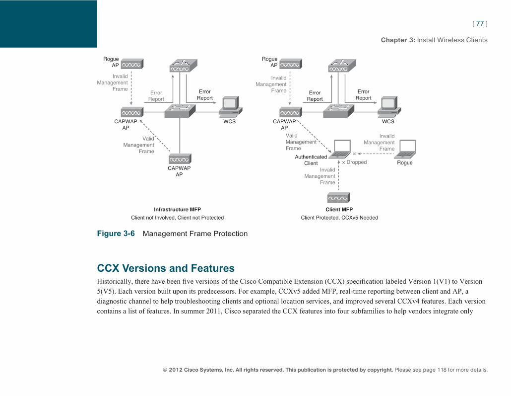
ptg7913109
[ 77 ]
© 2012 Cisco Systems, Inc. All rights reserved. This publication is protected by copyright. Please see page 118 for more details.
Chapter 3: Install Wireless Clients
RogueAP
RogueAP
InvalidManagement
Frame
ValidManagement
Frame
ErrorReport
ErrorReport
WCSCAPWAPAP
CAPWAPAP
Infrastructure MFP
Client not Involved, Client not Protected
Client MFP
RogueAuthenticated
Client
Client Protected, CCXv5 Needed
InvalidManagement
Frame
InvalidManagement
Frame
InvalidManagement
Frame
ValidManagementFrame
× Dropped
×
ErrorReport
ErrorReport
WCSCAPWAPAP
Figure 3-6 Management Frame Protection
CCX Versions and Features Historically, there have been five versions of the Cisco Compatible Extension (CCX) specification labeled Version 1(V1) to Version 5(V5). Each version built upon its predecessors. For example, CCXv5 added MFP, real-time reporting between client and AP, a diagnostic channel to help troubleshooting clients and optional location services, and improved several CCXv4 features. Each version contains a list of features. In summer 2011, Cisco separated the CCX features into four subfamilies to help vendors integrate only
ptg7913109
[ 78 ]
© 2012 Cisco Systems, Inc. All rights reserved. This publication is protected by copyright. Please see page 118 for more details.
Chapter 3: Install Wireless Clients
those features that are needed for their specific wireless clients (called application-specific devices, which are devices built for a specific function [for example, barcode scanners or VoWLAN phones] and therefore do not need all the CCX features that a data laptop would need). This is called the CCX Lite program, with four components:
■ Foundation (for standard CCX features for connectivity and security)
■ CCX Voice (for VoWLAN-specific features, such as QoS enhancements)
■ Location
■ Management (for connection reporting and troubleshooting)
Foundation is always needed to be certified CCX Lite, but the other subfamilies are optional.
The Cisco wireless infrastructure supports all CCX features on controller code release 7.0.116 and autonomous AP code release 12.4.25. No other wireless infrastructure vendor supports CCX (which means that you need a Cisco wireless infrastructure to support CCX). The CCX version supported on the client depends on the vendor and card. Not all vendors integrate the latest CCX version for all cards. This means that your wireless clients will benefit from the CCX features matching the CCX version they support (the client CCX version can be seen in the client detailed datasheet and on the client detailed monitor page on the controller through which the client associates).
As a CCNA Wireless, you do not need to know the details of all CCX features and version but are definitely expected to know the components of the CCX Lite program. Also, because support for fast roaming (with CCKM) depends on the security mechanism in use, you must know which version of CCX allows for which security mechanism support, as shown in Table 3-1 .
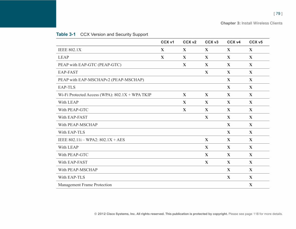
ptg7913109
[ 79 ]
© 2012 Cisco Systems, Inc. All rights reserved. This publication is protected by copyright. Please see page 118 for more details.
Chapter 3: Install Wireless Clients
Table 3-1 CCX Version and Security Support
CCX v1 CCX v2 CCX v3 CCX v4 CCX v5
IEEE 802.1X X X X X X
LEAP X X X X X
PEAP with EAP-GTC (PEAP-GTC) X X X X
EAP-FAST X X X
PEAP with EAP-MSCHAPv2 (PEAP-MSCHAP) X X
EAP-TLS X X
Wi-Fi Protected Access (WPA): 802.1X + WPA TKIP X X X X
With LEAP X X X X
With PEAP-GTC X X X X
With EAP-FAST X X X
With PEAP-MSCHAP X X
With EAP-TLS X X
IEEE 802.11i – WPA2: 802.1X + AES X X X
With LEAP X X X
With PEAP-GTC X X X
With EAP-FAST X X X
With PEAP-MSCHAP X X
With EAP-TLS X X
Management Frame Protection X
ptg7913109
[ 80 ]
© 2012 Cisco Systems, Inc. All rights reserved. This publication is protected by copyright. Please see page 118 for more details.
CCNA Wireless (640-722 IUWNE) Quick Reference
Chapter 4 Implement Basic WLAN Security Eavesdropping on a wired Ethernet infrastructure implies physical access to a switch port. Eavesdropping on a wireless network simply requires being able to receive an access point signal, which may reach hundreds of meters away from the AP physical location. For this reason, security is a key concern for any wireless network.
Authentication and Encryption Concepts Authentication is a process of finding out whether something is exactly what it appears to be. In wireless networks, authentication is used to prove the identity of the person or device trying to gain access and make sure that only the appropriate user accesses the applicable network. Authentication can be used to identify the machine connecting to the network, the user of this machine, or both. Authentication can be performed by using something you know (that is, a password), something you have (a smart card or a certificate), or something you are (fingerprint). None of these methods is perfect: Passwords can be forgotten, passwords and smartcards can be stolen, biometric sensors are complex to install in wireless networks. Choosing an authentication method is an arbitration between implementation and management complexity (for the admin or the user) and resulting security level.
Encryption is the process by which information (the plaintext) is transformed using a specific process (the cipher) to produce a result (the encrypted result) that is unreadable to anyone except those possessing a special knowledge, usually referred to as the key . Creating an encryption method is choosing an algorithm (a cipher method) and defining a key.
Encryption can be achieved using symmetric or asymmetric methods. With symmetric methods, the same process used to encrypt is reversed to decrypt. With asymmetric methods, the process used to encrypt, called the cipher , is different from the process used to decrypt, called the key . Both cipher and key rely on common mathematical properties that make sure they complement each other. The cipher can encrypt but not decrypt back. The key can decrypt but not reencrypt.
ptg7913109
[ 81 ]
© 2012 Cisco Systems, Inc. All rights reserved. This publication is protected by copyright. Please see page 118 for more details.
Chapter 4: Implement Basic WLAN Security
Symmetric methods usually are faster than asymmetric methods, but also easier to break. This is why asymmetric keys are often used for authentication (the process can be slow because it occurs once, but it must be very secure), while symmetric keys are often used for on-the-fly data encryption (the process must be fast and the key is changed regularly so that compromising a key does not allow access to more than a few chunks of data traffic).
In the case of wireless security, a key can be common to all users of an SSID (to authenticate and/or encrypt traffic) or unique to each user. Unique keys are more secure but require a more complex user authentication infrastructure.
Wireless IPS Wireless security is not only about proper authentication of users and encryption of users’ data, but also about preventing wireless attacks. Wireless threats are divided into four groups:
■ Rogue APs and rogue clients: A rogue AP is any AP that is not part of your infrastructure and a rogue client is any client associating to a rogue AP.
■ Ad-hoc networks: They interfere with one of your network channels and use weak security.
■ Client misassociations: An example would be if one of your clients was trying to connect to a saved, unsecure SSID, such as a well-known hotspot name.
■ Wireless attack: It can be passive if the attacker simply captures traffic for later analysis, or active if the attacker directly interacts with the network.
The Cisco Unified Wireless solution employs a wireless intrusion detection system that can detect rogues (APs, clients, and ad hoc) and wireless attacks. Any CAPWAP AP can detect rogues while scanning channels and alarms are visible in the controller. You can also enable Rogue Location Discovery Protocol (RLDP) to determine whether the detected rogue AP is in your network. With RLDP, a detecting AP pretends to be a wireless client, attempts to connect to the rogue AP, and sends a message to its controller port UDP 6352. If the message reaches the controller, the rogue is effectively connected to your network. Detected rogues can be contained. In that case, your APs spoof the rogue MAC address and send deauthentication messages to the rogue clients.
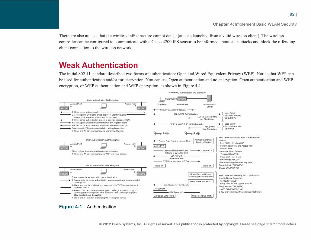
ptg7913109
[ 82 ]
© 2012 Cisco Systems, Inc. All rights reserved. This publication is protected by copyright. Please see page 118 for more details.
Chapter 4: Implement Basic WLAN Security
There are also attacks that the wireless infrastructure cannot detect (attacks launched from a valid wireless client). The wireless controller can be configured to communicate with a Cisco 4200 IPS sensor to be informed about such attacks and block the offending client connection to the wireless network.
Weak Authentication The initial 802.11 standard described two forms of authentication: Open and Wired Equivalent Privacy (WEP). Notice that WEP can be used for authentication and/or for encryption. You can use Open authentication and no encryption, Open authentication and WEP encryption, or WEP authentication and WEP encryption, as shown in Figure 4-1 .
AuthenticationServer
AuthenticatorSupplicant
Open Authentication, No Encryption
WPA/WPA2 Authentication and Encryption
Access PointA
Access PointB
1- Client sends probe request.2- Access points (A/B) send probe response. Client evaluates access point response, selects best access point.3- Client sends authentication request to selected access point (A).4- Access point (A) confirms authentication and registers client.5- Client sends association request to selected access point (A).6- Access point (A) confirms association and registers client.7- Client and AP can start exchanging unencrypted frames.
Security Capability Discovery
802.1x/EAP Authentication
Client Random Number, MIC,WPA IE or WPA2 IE Sent
PTK Done Message, MIC Sent
GTK Done, MIC
Access Point Random Number Sent
MIC, WPA IEor WPA2 IE Sent
Send Group Key (GTK), MIC
RADIUS-Based (PMK)Key Distribution
Or
“PSK is Used” (PSK not Exchanged)PSK (PMK)
Key Distribution
Steps 1–6 are the same as with open authentication.7- Client and AP can start exchanging WEP encrypted frames.
Steps 1–3 are the same as with open authentication.4- Access point (A) sends authentication response containing the unencrypted challenge text.5- Client encrypts the challenge text using one of its WEP keys and sends it to access point (A).6- Access point (A) compares the encrypted challenge text with its copy of the encrypted challenge text. If the text is the same, access point (A) will allow the client onto the WLAN.7- Client and AP can start exchanging WEP encrypted frames.
Open Authentication, WEP Encryption
Access PointA
Access PointB
WEP Authentication, WEP Encryption
Access PointA
Access PointB
Used Only IfSecurity CapabilitySet to 802.1x
WPA or WPA2 (Unicast) Four-Way HandshakeUsed to- Bind PMK to Client and AP- Confirm Both Client and Access Point Possess PMK- Generate Fresh Pairwise Transient Key (PTK)- Prove Each Peer Is Live- Synchronize PTK Use- Distribute Group Transient Key (GTK)Encrypted with TKlP (WPA)or AES-CCMP (WPA2)
WPA or WPAP2 Two-Way Group HandshakeUsed to Renew Group Key:- At Regular Interval- Every Time a Client Leaves the Cell Encrypted with TKlP (WPA)or AES-CCMP (WPA2) witha Key Encryption Key Unique to Each Cell Client
Used Only IfSecurity CapabilitySet to PSK
PMK PMK
AP/WLC GeneratesRandom Number
Group Random Numberand Group Key Generated
Derive PTK
Decrypt GTK
Unblocked Data Traffic Unblocked Data Traffic
Install TK Install TK
Derive PTK
Encrypt GTK with KEK
Figure 4-1 Authentication
ptg7913109
[ 83 ]
© 2012 Cisco Systems, Inc. All rights reserved. This publication is protected by copyright. Please see page 118 for more details.
Chapter 4: Implement Basic WLAN Security
With or without WEP, the first step to authentication is the client sending a probe request and the AP sending a probe response.
Once it knows the WLAN characteristics from the probe response, the client sends an authentication request. With Open system, the authentication phase is just a step to ensure that the client is a valid 802.11 device. The AP responds with an authentication response indicating a Success status.
With WEP authentication, the AP answers with a random string used as a challenge. The client encrypts the string with the WEP key and returns the encrypted result with the key index showing which key was used (up to four keys can be defined). The AP also encrypts the challenge string and compares the encrypted result to the value returned by the client. If both values match, the AP deduces that the client has the right WEP key and returns an authentication response indicating a Success status. Otherwise, the AP returns a Failure status.
When the authentication phase completes successfully, the client sends an association request asking the AP to register the client to the cell. The AP returns an association response that contains the client Association ID (AID, a number identifying the client in the cell). The client can then start sending and receiving data frames (without encryption or with WEP encryption depending on the AP configuration).
WEP uses a key that can be 40 bits or 104 bits long. When using WEP encryption, a key concern is randomness. To make sure that the same data content sent several times will not result in the same encrypted value, WEP adds to the static key an initialization vector (IV), which is a random 24-bit value added to the key and changed for any new packet to send (this 24-bit IV is the reason why some vendors talk about 64-bit and 128-bit WEP keys, counting 40+24 and 104+24). The data is encrypted using the RC4 algorithm and with a key stream that is a combination of the WEP key and the IV. As the IV is changed for each new packet, a different key stream will be used for each new packet, resulting in a different cipher text, even if the original data was the same. The IV is added to the frame header, in clear text, for the recipient to know which IV to use in the decryption phase. This is one of the many WEP weaknesses. WEP also does not authenticate each packet, so man-in-the-middle attacks are always a possibility. Because WEP uses a static key, hackers can easily crack the key by sniffing the air and stealing packets. Modern tools allow a 104-bit WEP key to be cracked within a few minutes. WEP also does not authenticate the infrastructure to the client. Only the client is authenticated to the infrastructure, thus allowing rogue APs to impersonate valid ones.
For all these reasons, WEP is deprecated and will soon be removed from the IEEE 802.11 standard.
Note WEP authentication/WEP encryption is considered weaker than Open authentication/WEP encryption be-cause during the WEP authentication process, a challenge string is sent in clear text then encrypted. This exchange can be used to crack the key of-fline. With WEP encryp-tion alone, data is sent encrypted but never in clear text.
ptg7913109
[ 84 ]
© 2012 Cisco Systems, Inc. All rights reserved. This publication is protected by copyright. Please see page 118 for more details.
Chapter 4: Implement Basic WLAN Security
MAC Authentication To increase the security of a wireless network, you can also use MAC authentication on the AP/WLC. Only those clients present in the MAC address list entered on the AP/WLC have permission to join the cell. This is not a strong security mechanism because spoofing a MAC address is quite easy.
802.1X/EAP Authentication The weakness in WEP was to provide one single key for all users in the cell. If this key is found, the WLAN is not protected anymore. Separating authentication from encryption is a key element to improve security. The IEEE worked to offer an alternative to single keys, reusing two existing security protocols: 802.1X and EAP.
802.1X The IEEE 802.1X protocol defines port-based access control. It defines three roles:
■ Supplicant: The machine that wants to access the network
■ Authenticator: The point of connection to the network, traditionally a switch in wired networks
■ Authentication server: A machine somewhere in the network that keeps a list of conditions by which access should be granted or refused.
When a supplicant connects to the authenticator, the authenticator closes its port except for authentication-related exchanges and asks the supplicant for credentials (a form of ID). The switch receives the ID from the supplicant and passes the ID information to the authentication server (typically a RADIUS server) that can verify the identification information. The RADIUS server responds to the switch with either a success or failure message. If the response is a success, the port will be opened and user traffic will be allowed to flow through the open port.
ptg7913109
[ 85 ]
© 2012 Cisco Systems, Inc. All rights reserved. This publication is protected by copyright. Please see page 118 for more details.
Chapter 4: Implement Basic WLAN Security
In the case of wireless, the AP (or the AP/WLC pair in a controller-based network) acts as the authenticator. The client first uses 802.11 Open authentication (authentication request – authentication response). The client then sends the association request (which is the wireless equivalent of connecting to the switch) and receives the Association response with the AID. The AP still does not allow the client traffic to flow through. The 802.1X process starts at this time. When the 802.1X process successfully completes, the client traffic is allowed to flow through the AP.
EAP The 802.1X protocol does not contain specific methods for wireless clients to send their credentials to the authentication server, nor does it specify how this authentication should occur. To solve this problem, the IEEE added the IETF Extensible Authentication Protocol (EAP) to 802.1X authentication in wireless networks. EAP describes headers that can be used to identify typical packets of an authentication dialog (request, challenge, success, failure). EAP does not describe the authentication method (and does not relate directly to 802.1X) but simply describe those headers.
In the IEEE 802.11 standard, 802.1X and EAP are used with an authentication method. The name often mentions the authentication method (for example, LEAP), sometimes EAP (for example, EAP-PEAP). Even if 802.1X is not mentioned in the method name, it is always used along with EAP to block the AP data port for the user until the authentication completes successfully.
RADIUS Remote Dial-In User Service (RADIUS) is the main protocol described for authentication in the 802.1X protocol. This means that, in the case of wireless connections, the supplicant exchanges 802.1X messages with the authenticator. The authenticator translates the 802.1X messages to RADIUS messages and forwards them to a RADIUS server. These two protocols act as a vehicle to carry an authentication dialog between the supplicant and the RADIUS server, using a specific authentication method (such as LEAP, EAP-FAST, EAP-TLS, or PEAP) and using EAP to identify each packet in the sequence.
A RADIUS server is required to handle the supplicant access request. A RADIUS server is a program that checks a set of conditions to grant or deny access. These conditions can be identity-based (username/password) or anything else (temperature, time or date, source VLAN, and so on). The RADIUS server also can return a profile to be applied to the supplicant (for example, “Access granted, user should be in VLAN 20”). The RADIUS server can be an external machine, but the autonomous AP and the WLC also embark a basic RADIUS server if needed. A RADIUS server uses, by default, UDP ports 1812 for authentication and 1813 for authorization.
ptg7913109
[ 86 ]
© 2012 Cisco Systems, Inc. All rights reserved. This publication is protected by copyright. Please see page 118 for more details.
Chapter 4: Implement Basic WLAN Security
Certificates Several secure authentication mechanisms used in wireless rely on certificates, and you should understand what certificates are and how they are used. Certificates are based on asymmetric keys and are better understood with an example. Alice wants to send a secret message to Bob. With asymmetric encryption, Alice generates two keys, A1 and A2. These keys are asymmetric: You need A1 to decrypt what A2 encrypts. If you encrypt with A1, you need A2 to decrypt. Alice makes one key public (for example, A2) and keeps A1 secret. Bob proceeds with the same logic and generates B1 and B2. Bob sends B2 to Alice. Alice encrypts her message with B2, and only B1 (which Bob keeps for himself) can decrypt that message. Alice sends A2 to Bob. Bob encrypts his answer with A2, and only A1 (which Alice keeps as her private key) can decrypt that answer.
This system is called public/private key system. Its limitations are twofold:
■ Because B2 is public, anybody could get B2. Pretend to be Alice and send an encrypted message to Bob. Bob needs to make sure that Alice is the real sender. To achieve this identity guaranty, Alice signs the message she sends by encrypting her signature with A1 (private key). If Bob can decrypt this signature with A2 (public key), he knows that the sender had A1 (key pairs are unique, only A1 can encrypt what A2 decrypts), so the sender had to be Alice (only Alice has A1).
■ Bob also must be sure that A2 really belongs to Alice (just like Alice needs to be sure that B2 really belongs to Bob). To authenticate these public keys, Alice and Bob ask a trusted third party (called Certification Authority, CA) to sign A2 and B2. Because Bob trusts the third party, he trusts that the trusted party verified Alice’s identity before signing Alice’s public key. Alice’s key is signed with the trusted third party’s private key T2. Bob has the trusted third-party public key T1 to verify the signature. In computers, well-known trusted authority public keys are preinstalled in operating systems (you can see them, for example, from Windows Explorer in Tools > Internet Options > Content > Certificates > Trusted Root Certification Authorities). Trust is a chain. Alice’s public key can be signed by a third party, which public key is signed by another third party that Bob trusts. This chain can go several levels deep and is called public key infrastructure (PKI). A network administrator can install a new trusted authority and install its public key on all the corporation PCs so that they trust the authority.
When Alice wants to send an encrypted message to Bob, she gets Bob’s public key. This key is signed by a trusted third party. This signed key is called a certificate. Alice verifies that she can decrypt the signature with the third party (CA) public key embedded in her computer. If the signature can be read, she trusts that the certificate is really Bob’s. Alice then encrypts the message with Bob’s
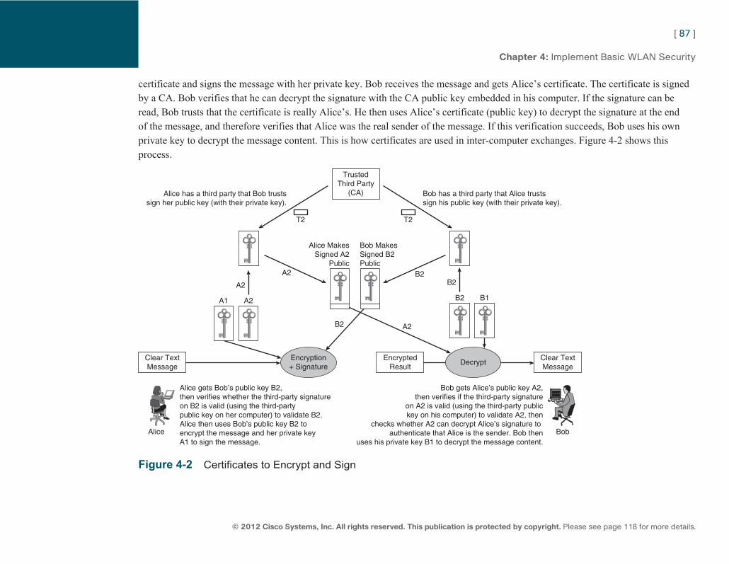
ptg7913109
[ 87 ]
© 2012 Cisco Systems, Inc. All rights reserved. This publication is protected by copyright. Please see page 118 for more details.
Chapter 4: Implement Basic WLAN Security
certificate and signs the message with her private key. Bob receives the message and gets Alice’s certificate. The certificate is signed by a CA. Bob verifies that he can decrypt the signature with the CA public key embedded in his computer. If the signature can be read, Bob trusts that the certificate is really Alice’s. He then uses Alice’s certificate (public key) to decrypt the signature at the end of the message, and therefore verifies that Alice was the real sender of the message. If this verification succeeds, Bob uses his own private key to decrypt the message content. This is how certificates are used in inter-computer exchanges. Figure 4-2 shows this process.
Clear TextMessage
TrustedThird Party
(CA)
Clear TextMessage
EncryptedResult
Bob has a third party that Alice trustssign his public key (with their private key).
Bob gets Alice’s public key A2,then verifies if the third-party signature
on A2 is valid (using the third-party publickey on his computer) to validate A2, then
checks whether A2 can decrypt Alice’s signature to authenticate that Alice is the sender. Bob then
uses his private key B1 to decrypt the message content.
Alice gets Bob’s public key B2,then verifies whether the third-party signatureon B2 is valid (using the third-partypublic key on her computer) to validate B2.Alice then uses Bob’s public key B2 to encrypt the message and her private keyA1 to sign the message.
Alice Bob
Alice has a third party that Bob trustssign her public key (with their private key).
Bob MakesSigned B2Public
Alice MakesSigned A2
Public
T2 T2
Encryption+ Signature
Decrypt
B1B2
B2B2A2
A2B2
A2A1
A2
Figure 4-2 Certificates to Encrypt and Sign
ptg7913109
[ 88 ]
© 2012 Cisco Systems, Inc. All rights reserved. This publication is protected by copyright. Please see page 118 for more details.
Chapter 4: Implement Basic WLAN Security
EAP Types
EAP-TLS Certificates are very secure because they provide both an encryption mechanism and a way to authenticate the message sender. EAP-TLS (Transport Layer Security) is an authentication mechanism used in wireless networks that relies on certificates. Key pairs (certificate and private key) are installed on the wireless client and on the RADIUS server. When EAP-TLS is in use, the initial 802.11 open authentication occurs, then the client sends an association request, the AP replies with an association reply and AID, and then the AP/WLC continues with an EAPSTART message, asking for the supplicant identity. The supplicant sends its identity (username). This ID is forwarded to the RADIUS server. The RADIUS server responds with its certificate. The supplicant verifies the RADIUS server certificate and sends its own certificate. Both ends now have authenticated each other and have a way to encrypt the messages they exchange. They use this secure connection to agree on a way to derive a main encryption key for the client’s traffic. This key is called the Pairwise Master Key (PMK). After this key is derived, the RADIUS server returns a Success message to the WLC/AP, along with the PMK (the RADIUS server does not need to remember or use the PMK, but simply to generate it and transmit it to the authenticator). The AP/WLC uses the PMK as a basis to generate encryption keys for the client traffic. These keys can be changed (rotated) at regular intervals to increase the security of the data exchange.
EAP-TLS is very secure and widely supported by most operating systems, but the need to deploy certificates on each client is sometimes a burden. EAP-TLS is used in secure environments where deploying and maintaining certificates for all users is necessary to ensure a high level of security.
EAP-FAST EAP-FAST (Flexible Authentication via Secure Tunneling) is a Cisco solution to provide a level of security equivalent to EAP-TLS without the burden of maintaining a complex certificate infrastructure.
EAP-FAST uses an EAP-FAST server. Only Cisco makes EAP-FAST servers, but EAP-FAST clients are more widely supported. EAP-FAST is built in three phases: phase 0, phase 1, and phase 2.
ptg7913109
[ 89 ]
© 2012 Cisco Systems, Inc. All rights reserved. This publication is protected by copyright. Please see page 118 for more details.
Chapter 4: Implement Basic WLAN Security
In phase 0, the client obtains protected access credentials (PAC) from the EAP-FAST server (this is similar in concept to installing a key pair on the client with EAP-TLS). This PAC contains a PAC key for the client to encrypt and decrypt traffic, an Authority ID (A-ID) that uniquely identifies the EAP-FAST server generating the PAC, and a PAC Opaque section. The server generates and then forgets the PAC.
In phase 1, the client tries to access the network. Open 802.11 authentication and association occur and the AP/WLC sends the EAPSTART/ send your ID message. The client sends its ID. The RADIUS server, which is also the EAP-FAST server, returns the A-ID. The client verifies if it has a PAC generated by this A-ID. If the client has one, it returns the PAC Opaque back to the server.
This is where EAP-FAST is very smart: The PAC Opaque actually contains the client PAC-key, but encrypted in a way that only the server can decrypt. The server extracts the client PAC-key from the PAC Opaque. At this point, both the client and the server have the client PAC-key and can use it to exchange encrypted data.
At the end of phase 1, the client has identified the server (as only the applicable server that can decrypt the PAC Opaque) but the client is not authenticated yet (anyone could capture and return another device’s PAC Opaque). Therefore, a phase 2 starts where the server asks the client, through the encrypted tunnel created with phase 1, to authenticate using Generic Token Card (EAP-FAST v1), MsCHAPv2 username and password pair, or TLS (EAP-FAST v2, sometimes called v1a). Once the authentication completes, both sides agree on a way to generate a PMK, and the RADIUS server forwards the PMK to the AP/WLC, just like for EAP-TLS.
EAP-FAST is deemed almost as secure as EAP-TLS but requires a Cisco EAP-FAST server. Client support is less wide than for EAP-TLS.
EAP-PEAP Protected EAP (PEAP) could be seen as a compromise between EAP-TLS, which relies entirely on a certificate-based infrastructure, and EAP-FAST, which does not require any certificate.
As usual, Open 802.11 authentication then association and EAPSTART ID Request occur. The client returns an ID (that can be a fake ID). The RADIUS server returns its certificate (PEAP requires a certificate, but only on the server side). The client does not have a certificate (this is why PEAP is easier to maintain and deploy than EAP-TLS). Instead, the client generates a master encryption key, encrypts this key using the server certificate, and sends the encrypted key to the authentication server. From the perspective of
Note Do not confuse the asso-ciation ID (AID) and the Authority ID (A-ID).
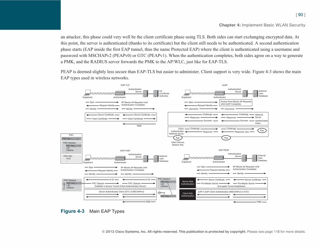
ptg7913109
[ 90 ]
© 2012 Cisco Systems, Inc. All rights reserved. This publication is protected by copyright. Please see page 118 for more details.
Chapter 4: Implement Basic WLAN Security
an attacker, this phase could very well be the client certificate phase using TLS. Both sides can start exchanging encrypted data. At this point, the server is authenticated (thanks to its certificate) but the client still needs to be authenticated. A second authentication phase starts (EAP inside the first EAP tunnel, thus the name Protected EAP) where the client is authenticated using a username and password with MSCHAPv2 (PEAPv0) or GTC (PEAPv1). When the authentication completes, both sides agree on a way to generate a PMK, and the RADIUS server forwards the PMK to the AP/WLC, just like for EAP-TLS.
PEAP is deemed slightly less secure than EAP-TLS but easier to administer. Client support is very wide. Figure 4-3 shows the main EAP types used in wireless networks.
AuthenticationServer CA
(CertificateAuthority)
EAP-TLS
AuthenticatorSupplicant
Start
ldentity ldentity
AP Blocks All Requests UntilAuthentication CompletesRequest Identity
Server Certificate
Client Certificate Client Certificate
PMK
Server Certificate
AuthenticationServer External
UserDatabase
LEAP
AuthenticatorSupplicant
Start
Username Username
Access Point Blocks All RequestsUntil LEAP Completes
Request Identity
Challenge Challenge
Success Success
RADIUSServer
AuthenticatesClient
Response Response
ClientAuthenticates
RADIUS Server
Client DerivesSession Key
AuthenticationServer External
UserDatabase
EAP-PEAP
AuthenticatorSupplicant
Start
ldentity ldentity
AP Blocks All Requests UntilAuthentication CompletesRequest Identity
Key
Key Key
Server CertificateServer-Side
Authentication Pre-Master SecretEncrypted Tunnel Established
Pre-Master Secret
Server Certificate
PMK
EAP in EAP Client Authentication (MSCHAPv2 or GTC)Client-Side
Authentication
ldentity ldentity
AuthenticationServer External
UserDatabase
EAP-FAST
AuthenticatorSupplicant
PAC-Opaque: PAC Key = I-ID Lifetime ...
Start AP Blocks All Requests UntilAuthentication CompletesRequest Identity
A-ID A-ID
PAC OpaqueEstablish a Secure Tunnel (Client Authenticates Server)
PAC Opaque
PMK
Server Authenticates Client (GTC of MSCHAPv2)
PAC-Opaque: PAC Key = I-ID Lifetime ...
PAC-Info: A-ID ...
PAC-Opaque: PAC Key = I-ID Lifetime ...
PAC Key =
PAC Key =
PAC
Challenge
Response
Challenge
Response, Key
Figure 4-3 Main EAP Types
ptg7913109
[ 91 ]
© 2012 Cisco Systems, Inc. All rights reserved. This publication is protected by copyright. Please see page 118 for more details.
Chapter 4: Implement Basic WLAN Security
Other EAP Types EAP-TLS, EAP-FAST, and PEAP are the most common EAP types used in modern wireless networks. Because EAP is flexible, you might find other, less common types. Among them, Lightweight EAP (LEAP) is probably the most famous. It was created by Cisco and released in late 2000 to replace WEP. The initial process is the same as the other EAPs. After EAPSTART and ID request, the client sends its ID, which is the username. The server then sends a challenge string that the client encrypts with a Cisco proprietary algorithm and returns to the server. The server verifies that the client encrypted the challenge string correctly. This validates the client ID. The client then sends a challenge string to the server, and the process occurs in reverse so that the client can authenticate the server. When the authentication completes, both sides have a way to exchange encrypted material (because they have a common key). LEAP is no longer widely employed because the algorithm used to encrypt the challenge has been compromised. An eavesdropper can capture the exchange, read the client ID (this is the real ID, sent in clear text), and then use a cracking tool to extract the key from the challenge exchange. For this reason, passwords should be strong and LEAP should be limited to devices without a stronger authentication possibility.
There are many other EAP-based authentication mechanisms, such as EAP-Subscriber Identity Module (EAP-SIM) or EAP-Message Digest 5 (MD5). They are not commonly used in wireless networks.
WPA/WPA2
WPA The IEEE 802.11 working group’s first concern was to offer a possible replacement for cellwide common preshard keys. The second concern was to increase the encryption security by finding a replacement for WEP. Both tasks were assigned to the 802.11i working group. But developing an amendment to the protocol takes time, and the industry, with the boom of wireless networks and WEP
ptg7913109
[ 92 ]
© 2012 Cisco Systems, Inc. All rights reserved. This publication is protected by copyright. Please see page 118 for more details.
Chapter 4: Implement Basic WLAN Security
weaknesses, could not wait. This is why, in 2003, the Wi-Fi Alliance decided to publish a certification for vendors implementing a better scheme than WEP, called WPA (Wi-Fi Protected Access). WPA was based on draft version 3 of the 802.11i amendment. WPA offers two authentication mechanisms:
■ An Enterprise mode using 802.1X/EAP, as explained earlier and implying individual user authentication through a RADIUS server)
■ A Personal mode using Pre-Shared Keys (PSK) for smaller networks. In both cases, a PMK is generated (for Personal mode, the PSK is the PMK). The RADIUS passes the PMK to the WLC.
A four-way handshake then occurs between the client and the WLC. This phase is used to confirm that both sides have the PMK, and validate the security parameters that were negotiated during the authentication phase. It is also used to generate another key, the Pairwise Transient Key (PTK) that will be used as a base to generate encryption keys (that will be changed at regular intervals and derived from the PTK). Both the client and the controller (through the AP) use nonces (number once, a number used only once in an authentication exchange, to avoid replay attacks). The WLC keeps the PMK, and only sends the PTK to the client AP.
The client also needs a Group Transient Key (GTK). As each client has an individual and changing key, how would devices in the cell send broadcasts? The GTK is used to encrypt this type of message. The AP/WLC generates a Groupwise Master Key (GMK), and then derives a GTK. This GTK is sent encrypted (using the client individual encryption key) through a two-way handshake after the individual key four-way handshake for each new client. Every time a client leaves the cell, and at regular intervals, the AP generates a new GTK and distributes it to the cell clients. This is called broadcast key rotation .
WPA encryption relies on RC4, just like WEP (for backward compatibility) but with a stronger implementation called Temporal Key Integrity Protocol (TKIP). The IV is brought up to 48 bits (every bit added doubles the number of possible keys, making brute-force cracking a lot harder to achieve). The encryption key is built on the PTK, the sender MAC address, the IV, and an index number for the packet to encrypt. Because this index number changes over time (thus the name Temporal in TKIP) and for each new packet (this is called per-packet key hashing), a WPA encrypted packet is valid for only about 2 seconds, making replay attacks (where you resend a captured valid packet) almost impossible. To avoid packet forgery (where a valid packet is captured and modified), WAP adds a Message Integrity Check (MIC, sometimes called Michael) inside the encrypted payload. This 8-byte MIC is a checksum taking
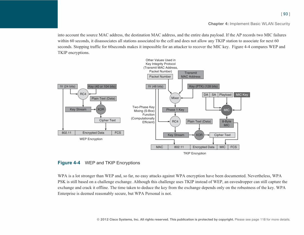
ptg7913109
[ 93 ]
© 2012 Cisco Systems, Inc. All rights reserved. This publication is protected by copyright. Please see page 118 for more details.
Chapter 4: Implement Basic WLAN Security
into account the source MAC address, the destination MAC address, and the entire data payload. If the AP records two MIC failures within 60 seconds, it disassociates all stations associated to the cell and does not allow any TKIP station to associate for next 60 seconds. Stopping traffic for 60 seconds makes it impossible for an attacker to recover the MIC key. Figure 4-4 compares WEP and TKIP encryptions.
RC4
XOR
Mixer
RC4
MIC
Cipher Text
802.11 FCSEncrypted Data
MAC MIC FCSEncrypted Data802.11
DA SA Playload MIC Key
8-ByteMIC
WEP Encryption
TKIP Encryption
IV (24 bits) IV (48 bits)
Plain Text (Data)
Key Stream
Key (40 or 104 bits) Key (PTK) (128 bits)
Key Stream
Phase 1 Key
TransmitMAC Address
Cipher Text
Packet Number
Other Values Used inKey Integrity Protocol
(Transmit MAC Address,Packet Number)
Plain Text (Data)
XOR
Two-Phase KeyMixing (S-Box)
Function(Computationally
Efficient)
Figure 4-4 WEP and TKIP Encryptions
WPA is a lot stronger than WEP and, so far, no easy attacks against WPA encryption have been documented. Nevertheless, WPA PSK is still based on a challenge exchange. Although this challenge uses TKIP instead of WEP, an eavesdropper can still capture the exchange and crack it offline. The time taken to deduce the key from the exchange depends only on the robustness of the key. WPA Enterprise is deemed reasonably secure, but WPA Personal is not.

ptg7913109
[ 94 ]
© 2012 Cisco Systems, Inc. All rights reserved. This publication is protected by copyright. Please see page 118 for more details.
Chapter 4: Implement Basic WLAN Security
Notice that the 802.11i draft used as the base for WPA described a potential future algorithm to replace RC4, AES, but the Wi-Fi Alliance did not include it in the WPA certification. Some vendors offer WPA with AES, others don’t.
WPA2 The 802.11i amendment was ratified in June 2004. The Wi-Fi Alliance then published an update to WPA called WPA2 (WPA is sometimes called WPAv1), implementing the entire 802.11i amendment.
With WPA2, 802.1x/EAP and PSK are still present. The main change is that the encryption mechanism does not use the RC4 algorithm anymore but instead uses the AES algorithm (advanced Encryption Standard), to which an additional security mechanism (Counter Mode with CBC-MAC Authentication, or CCMP) was added. This algorithm is a lot stronger than RC4 but required a hardware upgrade of a wireless card only able to run RC4.
WPA2 (and 802.11i) also allows TKIP for backward compatibility. Nevertheless, configuring a WLAN to use WPA2 while allowing both AES/CCMP and TKIP is not recommended because some clients get confused by this mode and cannot associate. 802.11i also describes two new mechanisms:
■ Key caching: When a client disassociates from a cell, the PMK is kept for one hour. If the client comes back, it can resume the encrypted communication without needing to reauthenticate.
■ Pre authentication: When a client authenticates to an AP, the AP can spoof the client MAC address and authenticates in its name to the neighboring APs, thus speeding the client roaming process. The 802.11i does not describe how the AP knows about the neighboring APs.
Key caching is also implemented by CCKM on Cisco networks (but CCKM applies to any encryption/authentication mechanism depending on the CCX version used, not just to WPA2). With CCKM, pre-authentication is not necessary because the credentials follow the client as it roams.
ptg7913109
[ 95 ]
© 2012 Cisco Systems, Inc. All rights reserved. This publication is protected by copyright. Please see page 118 for more details.
Chapter 4: Implement Basic WLAN Security
Wireless Security Configuration
Autonomous AP Wireless security is configured on the autonomous AP in several steps:
■ If you use VLANs, create VLANs from Services > VLANs and associate each VLAN to one or both radios.
■ From Security > Encryption manager, choose the encryption to use for your radio VLANs (for example, WEP 40/128, WPA/TKIP, or WPA2/AES with or without TKIP support). If you choose WEP, you can enter up to four keys.
■ If you are using 802.1X/EAP, from Security > Server Manager , enter the IP address of the RADIUS server to use, with a shared secret. You can enter several servers. The AP IP address itself can be entered if you plan to use the AP integrated basic RADIUS server (supporting LEAP, EAP-FAST, and MAC authentication).
■ If you entered a RADIUS server address, also enter the AP IP address as a RADIUS client (allowed to query the RADIUS) on the RADIUS server, with the same shared secret as the one defined on the AP. This is also valid if you use the AP integrated RADIUS server (enter the AP IP address as a RADIUS client in Security > Local RADIUS Server ). Also, create the users on the RADIUS server.
■ From Security > SSID Manager , create the SSID. Associate the SSID to a VLAN or a radio, define whether the SSID uses Open (with or without 802.1X/EAP) authentication, shared key or LEAP, whether WPA or WPA2 should be used, and which RADIUS server should be used (if applicable). If you use WPA or WPA2 Personal, enter the WPA/WPA2 PSK.
■ You can then enable the radio on which the SSID is set.
Notice that the AP does not recognize which 802.1X/EAP method to use. This is also true on the controllers. The EAP method chosen is negotiated between the authentication server and the supplicant. The authenticator is not involved in this negotiation, and just needs to know whether the authentication phase uses EAP (implying a RADIUS server) or PSK (no RADIUS needed).
ptg7913109
[ 96 ]
© 2012 Cisco Systems, Inc. All rights reserved. This publication is protected by copyright. Please see page 118 for more details.
Chapter 4: Implement Basic WLAN Security
Controller If you want to use the RADIUS server integrated to the controller, start by creating a Local EAP profile from Security > Local EAP Profiles , and decide which EAP method to allow (EAP-TLS, LEAP, EAP-FAST, and/or PEAPv0/v1). If you use EAP-FAST, you can also configure (optionally) the A-ID number and A-ID information (description), the server key, and the PAC lifetime (TTL). You can use a local list of users, or an external LDAP server. If you use an external RADIUS server, enter the server IP address and shared secret from Security > RADIUS > Authentication Servers . You can define up to 17 RADIUS servers. From that same page, you can define whether the controller will be identified on the RADIUS server with its Management Interface IP address, MAC address, or the AP MAC address (do not forget to enter the relevant information to define the controller as a RADIUS client on the RADIUS server).
Proceed to create the WLAN from WLANs > WLANs > WLANs . On the Security > Layer 2 tab, choose WEP or WPA and/or WPA2, allowing TKIP, AES, or both. Also choose whether MAC authentication should occur. Choose whether the WLAN key is managed using PSK, 802.1X/EAP, or CCKM. If you use RADIUS, you can point to one or several (up to three) specific RADIUS servers or a Local EAP Profile from the AAA Servers tab.
From the Advanced tab, you can choose whether the RADIUS can send a profile that overrides the general settings of the WLAN. This is called identity based networking and is activated by checking the Allow AAA Override checkbox. Notice that the Local EAP profile is always a backup. If a RADIUS server is configured for the WLAN, the controller will use that RADIUS server first. If the RADIUS server does not answer (or is not defined), the controller will use the RADIUS servers defined in Security > RADIUS > Authentication Servers . If those servers do not reply (or are not defined or are defined but not set for network user authentication), then the controller will use the Local EAP profile defined for the WLAN. Figure 4-5 illustrates the authentication configuration on a controller.
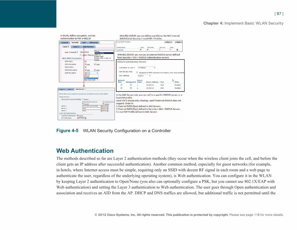
ptg7913109
[ 97 ]
© 2012 Cisco Systems, Inc. All rights reserved. This publication is protected by copyright. Please see page 118 for more details.
Chapter 4: Implement Basic WLAN Security
Figure 4-5 WLAN Security Configuration on a Controller
Web Authentication The methods described so far are Layer 2 authentication methods (they occur when the wireless client joins the cell, and before the client gets an IP address after successful authentication). Another common method, especially for guest networks (for example, in hotels, where Internet access must be simple, requiring only an SSID with decent RF signal in each room and a web page to authenticate the user, regardless of the underlying operating system), is Web authentication. You can configure it in the WLAN by keeping Layer 2 authentication to Open/None (you also can optionally configure a PSK, but you cannot use 802.1X/EAP with Web authentication) and setting the Layer 3 authentication to Web authentication. The user goes through Open authentication and association and receives an AID from the AP. DHCP and DNS traffics are allowed, but additional traffic is not permitted until the
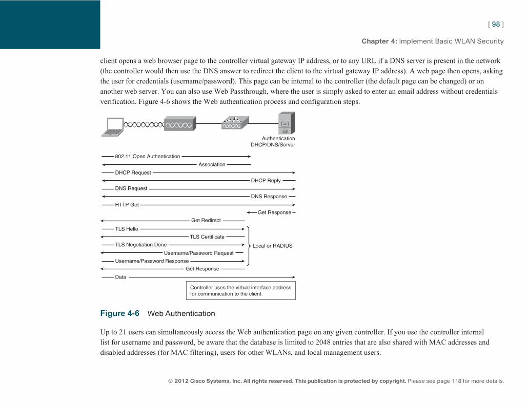
ptg7913109
[ 98 ]
© 2012 Cisco Systems, Inc. All rights reserved. This publication is protected by copyright. Please see page 118 for more details.
Chapter 4: Implement Basic WLAN Security
client opens a web browser page to the controller virtual gateway IP address, or to any URL if a DNS server is present in the network (the controller would then use the DNS answer to redirect the client to the virtual gateway IP address). A web page then opens, asking the user for credentials (username/password). This page can be internal to the controller (the default page can be changed) or on another web server. You can also use Web Passthrough, where the user is simply asked to enter an email address without credentials verification. Figure 4-6 shows the Web authentication process and configuration steps.
AuthenticationDHCP/DNS/Server
Controller uses the virtual interface addressfor communication to the client.
Local or RADIUS
802.11 Open Authentication
DHCP Request
Association
DHCP Reply
DNS Request
DNS Response
HTTP Get
Get Response
Get Redirect
TLS Hello
TLS Certificate
TLS Negotiation Done
Username/Password Request
Username/Password Response
Get Response
Data
Figure 4-6 Web Authentication
Up to 21 users can simultaneously access the Web authentication page on any given controller. If you use the controller internal list for username and password, be aware that the database is limited to 2048 entries that are also shared with MAC addresses and disabled addresses (for MAC filtering), users for other WLANs, and local management users.
ptg7913109
[ 99 ]
© 2012 Cisco Systems, Inc. All rights reserved. This publication is protected by copyright. Please see page 118 for more details.
CCNA Wireless (640-722 IUWNE) Quick Reference
Chapter 5 Operate Basic WCS Controllers provide a single point of management to many access points, but many networks have several controllers and require a single point of management for these controllers. Cisco Wireless Control System (WCS) provides this single point by allowing administrators to design, control, and monitor enterprise wireless networks from a central location. Cisco WCS also provides many other features, such as planning and location tracking. WCS is a service installed on Windows or Linux that can be accessed through a web interface. An older platform for management of autonomous APs, the Wireless LAN Solution Engine (WLSE), also can be migrated to WCS, which can be useful when migrating an autonomous AP network to a controller-based solution. WCS successor, NCS, is an appliance and can also be installed as VMWare image. NCS is not on the IUWNE exam.
Versions and Licenses WCS is available in two main license versions: WCS Base and WCS Plus. WCS Plus adds to the base version support for on-demand location of wireless devices (clients or rogues), Cisco Spectrum Expert stations, and interferers with a location accuracy of 90% of collected positions within 7 meters of the real device location (the calculated location from the collected positions usually offers a better final accuracy). WCS Plus can also manage Mobility Service Engines (MSE) to locate up to 18,000 devices per engine. The Cisco WCS base version offers location up to the closest AP.
WCS license is based on the number of APs to support. You can buy single-server licenses (for 50, 100, and up to 500 APs) or enterprise licenses (that can be deployed on a single or multiple servers running WCS) for up to 50,000 APs.
If your network has stations running Cisco Spectrum Expert, you can consolidate the findings in WCS. You need a specific license for this support in WCS (called the Advanced feature license for AP and CSE support and Advanced Feature Spectrum Intelligence for CSE support alone). Notice that CleanAir APs (3500 and 3600 series) simply need a standard AP license.
ptg7913109
[ 100 ]
© 2012 Cisco Systems, Inc. All rights reserved. This publication is protected by copyright. Please see page 118 for more details.
Chapter 5: Operate Basic WCS
When you install WCS over multiple servers, you need a central point of management for these WCS instances. Cisco WCS Navigator is a service accessed through a web interface that allows this single point of management. Navigator is a sort of WCS for WCSs, installed on the same type of platform and the same way as WCS. Navigator can be bought and installed separately but also is included when you buy 10,000 or 50,000 AP licenses for WCS. One Navigator can manage up to 20 Cisco WCS management platforms. Each WCS must be added manually to Navigator. WCS and Navigators communicate with SOAP/XML over HTTPS and use the same software release to communicate properly.
WCS Interface Once WCS is installed, you can access the management interface by opening a secure (HTTPS) web browser session to the IP address of the WCS server. Internet Explorer 7 and Firefox 3.5 and later are the supported clients, with the Flash plug-in. The initial administrative username is root, with the password defined during the installation phase. You can change this password and manage administrative users (create, modify, and delete users and groups and their respective authentication parameters and authorizations) from the Administration > AAA menu. Your users can belong to one or several of the following groups:
■ Admin: Monitor and configure WCS operations; perform all system administration tasks except administering WCS user accounts and passwords
■ SuperUser: Monitor and configure WCS operations; perform all system administration tasks, including administering WCS user accounts and passwords
■ Root: Same rights as SuperUser but only one user can be assigned to this group upon installation
■ ConfigManagers: Monitor and configure WCS operations
■ System Monitoring: Monitor WCS operations
■ Users Assistant: Local net user (all wireless users) administration only
■ Lobby Ambassador: Guest users (Webauth WLANs) administration only
■ Monitor Lite: Monitoring of devices location
■ North Bound API User: Used only with Navigator
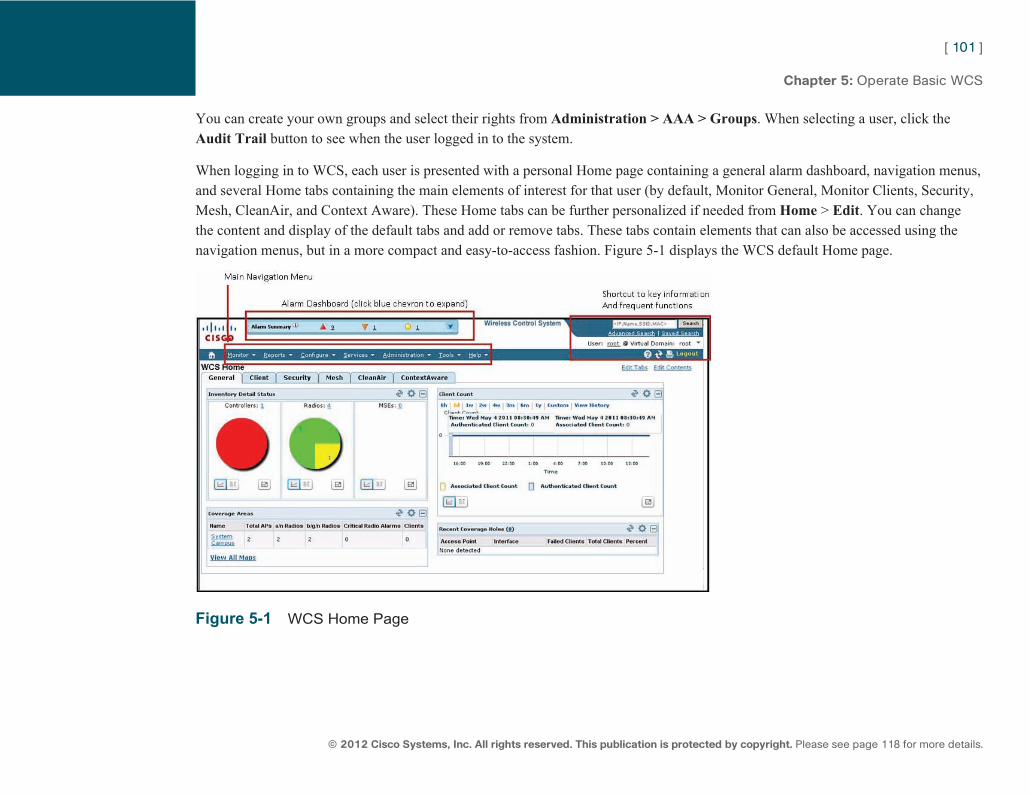
ptg7913109
[ 101 ]
© 2012 Cisco Systems, Inc. All rights reserved. This publication is protected by copyright. Please see page 118 for more details.
Chapter 5: Operate Basic WCS
You can create your own groups and select their rights from Administration > AAA > Groups . When selecting a user, click the Audit Trail button to see when the user logged in to the system.
When logging in to WCS, each user is presented with a personal Home page containing a general alarm dashboard, navigation menus, and several Home tabs containing the main elements of interest for that user (by default, Monitor General, Monitor Clients, Security, Mesh, CleanAir, and Context Aware). These Home tabs can be further personalized if needed from Home > Edit. You can change the content and display of the default tabs and add or remove tabs. These tabs contain elements that can also be accessed using the navigation menus, but in a more compact and easy-to-access fashion. Figure 5-1 displays the WCS default Home page.
Figure 5-1 WCS Home Page
ptg7913109
[ 102 ]
© 2012 Cisco Systems, Inc. All rights reserved. This publication is protected by copyright. Please see page 118 for more details.
Chapter 5: Operate Basic WCS
The alarm dashboard displays alerts for elements occurring in the network, with three colors for three levels of gravity:
■ Red: Critical alarm
■ Orange: Major alarm
■ Yellow: Minor alarm
Click the blue down arrow at the right of the Alarm Summary dashboard to expand the alarm summary and see the number of alarms per category, which include
■ Access Points
■ Controllers
■ Coverage Holes
■ Mesh Links
■ Mobility (location-related alarms)
■ Malicious AP (rogues classified as malicious)
■ Unclassified AP (rogues that have not been classified yet)
■ Security (attacks or client security events)
■ WCS (failures or license issues)
Click a category or alarm type to display a page listing all reported alarms for that category or type. You can then click each alarm event to get more details. For each alarm event, the upper-right drop-down list enables you to assign the alarm to yourself (you will be taking care of the alarm event), unassign it, delete, clear, or acknowledge the alarm. Delete removes the alarm (WCS forgets about it), Clear removes the alarm from the list (but the alarm is kept in the WCS database and can be searched for), and Acknowledge removes the alarm from the list and prevents WCS from displaying the alarm if it occurs again. The validity of each action is seven days (the alarm reappears in the list if it reoccurs seven days or more in the future). From the Monitor > Alarms page, you can also
Note In older versions of WCS, rogue AP alarms used to be classified as major (and malicious by default). In WCS 7.0, they are classified as mi-nor alarms (and unclassi-fied by default).
ptg7913109
[ 103 ]
© 2012 Cisco Systems, Inc. All rights reserved. This publication is protected by copyright. Please see page 118 for more details.
Chapter 5: Operate Basic WCS
configure email notifications to decide which alarm notifications should be forwarded to which email address. If you configure email notifications, you also must configure an SMTP server for WCS to be able to send emails, from Administration > Settings > Mail server Configuration .
You can change the severity for any alarm-generating event. From the Monitor > Alarms page, choose the Severity Configuration option and click Go . A new page displays all the possible alarm events and their current severity level. Check any alarm, choose a new severity level, and click Go to apply that new severity level to the selected alarm.
You can administer the network by using the navigation menus, but WCS is also built to automatically run tasks in the background (such as auditing the controllers and AP configuration to update the WCS parameters, clean up the WCS database, and so on). From Administration > Background Tasks , you can see the list of these tasks and change the way they occur (activate or deactivate task recurrence and configure task interval).
WCS logs events. These logs are configured from Administration > Logging . You can define what elements should be logged, the maximum size of each log file (4 MB by default), and the number of files of each logged category you want to keep (five by default).
Logging is about events occurring within the WCS engine (faults, reports, configuration changes, and so on). WCS also keeps track of network-related events (wireless client associations, APs, and controller details). These elements are aggregated over time to save hard drive space. You can configure this aggregation from Administration > Settings > Data Management to decide how long the hourly aggregated activity (default 31 days), the daily aggregated activity (default 90 days), and the weekly aggregated activity (default 54 weeks) should be retained.
WCS also enables you to generate many reports that are helpful to analyze the network activity. WCS can generate three types of reports:
■ Current: Provides a snapshot of the current activity
■ Historical: Retrieves data from the devices (WLCs and APs) periodically and stores it in the Cisco WCS database
■ Trend: Generates a report using aggregated data
ptg7913109
[ 104 ]
© 2012 Cisco Systems, Inc. All rights reserved. This publication is protected by copyright. Please see page 118 for more details.
Chapter 5: Operate Basic WCS
You can access the general report launch pad page from the Reports menu. You can access the Reports Launchpad page to manage your reports. From the Reports general menu, you can also directly access the Saved reports page or the Scheduled run result page. From the Report Launchpad page, you can see the list of all possible reports, classified by categories. Hover your mouse over a report to get a pop-up window with more information about the report, click the report itself to see the list of reports of this type that were created, or click New to create a new report. When you create a report, a Customize button enables you to choose which items should be displayed in the report. You can then save the report, run it immediately, or run it in the future (Schedule). You can then choose the date and time when the report should run, and choose whether the report should run once or with which recurrence (hourly, daily, weekly, or monthly). The result of the report can be saved in CSV or PDF format and saved to a destination folder and filename of your choice, or sent to an email address of your choice.
Controllers and APs Management WCS communicates with the controllers using SNMP (not CAPWAP). WCS does not communicate directly with the CAPWAP APs. You can add controllers to WCS from the Configure > Controllers tab, entering the controller Management IP address and SNMP values (SNMP v2c communities or SNMP v3 users) to use. You can also enter the controller username and password to allow WCS and execute CLI templates (make sure that the user you enter has RW rights on the controller). The values you enter must match the ones defined on the controller. When added to WCS, the controller brings its APs and registers the WCS as a trap receiver.
Configuring controllers and APs by using Cisco WCS can be accomplished in two ways. The first way is to manually configure the controller or the AP settings on an individual basis; each configuration option that can be configured through the controller interface can also be configured through the WCS by navigating to Configure > Controllers (or Configure > APs ) and clicking the device to configure. The main difference between the WCS and the controller interface is that WCS enables you to configure more than one controller at a time. For example, you can disable a WLAN on several controllers in one click in WCS, whereas you would need to configure each controller to achieve the same purpose through the controller interface.
The second method of configuration is through templates. Templates let you create a configuration object and then propagate it to one or more Cisco WLCs or APs on the network, without the need to reenter configurations. Templates offer an easy way to apply parameters consistently across multiple controllers or APs and keep track of what configuration item was deployed to what device, at what time in the past. Templates are created from Configure > Controller Templates Launchpad for controller templates and
ptg7913109
[ 105 ]
© 2012 Cisco Systems, Inc. All rights reserved. This publication is protected by copyright. Please see page 118 for more details.
Chapter 5: Operate Basic WCS
Configure > AP Configuration > Templates > Lightweight APs for CAPWAP AP templates. Create the template you need, save it, and then apply it to the devices where it is needed. Templates can be saved and applied later to additional controllers. Templates can be manually created or can be taken from the existing configuration of controllers. By allowing an item configured on a controller to be used as a template, existing configurations can easily be copied from controller to controller. You can also apply a template to a controller or an AP, then override this configuration by configuring the controller or AP differently.
When controllers and APs are configured via both WCS and the controller interface, mismatches may appear. Audits enable you to compare the running configuration on a controller or an AP to the configuration held in the Cisco WCS database. You can access the audit option from Configure > Controllers or Configure > Access points , by selecting a device and choosing Audit from the drop-down list. If a difference is found, you can choose to update WCS database (Refresh Config from Controller/AP) or push the WCS recorded configuration back to the device (Restore WCS Values to Controller/AP).
Maps Management An important feature of the Cisco Wireless Control System (WCS) is its capability to provide a graphical representation of the wireless network using maps. Maps can be used to show access point (AP) coverage or to locate devices. Information can be provided to Cisco WCS to enhance the accuracy of the coverage area display. To use the maps feature, navigate to Monitor > Maps . The page provides access to the various map displays and details. From this page, you can create a campus map and add outdoor areas or buildings and floors. When creating a campus, outdoor area, or floor map, you can also import a graphical background to help the visualization (supported formats are .PNG, .JPG, .JPEG, and .GIF).
You can then add APs to each floor or outdoor area by choosing the Add APs option, selecting APs known to WCS and not yet assigned to another map, indicating the AP height and antenna type and orientation, and then dragging and dropping the AP to its location on the map or inputting the coordinates of the location. You then see the heat map of each AP. The AP icon color also informs you about the AP radio status. For example, green shows that the AP radio has no fault, yellow shows that the AP radio has a minor fault, and red shows that the AP radio has a major fault. A blinking access point icon indicates that an interference, noise, coverage, or load profile failure alarm is pending against this access point. If a radio is disabled, a small “x” appears in the middle of the icon. The RF prediction that is completed is based on the map and on the effort you have put into the map. You can use the map editor tool to create walls, doors, windows, and obstructions. If done properly, the map uses the data in the RF prediction algorithm to
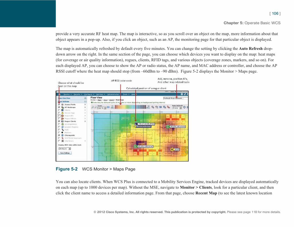
ptg7913109
[ 106 ]
© 2012 Cisco Systems, Inc. All rights reserved. This publication is protected by copyright. Please see page 118 for more details.
Chapter 5: Operate Basic WCS
provide a very accurate RF heat map. The map is interactive, so as you scroll over an object on the map, more information about that object appears in a pop-up. Also, if you click an object, such as an AP, the monitoring page for that particular object is displayed.
The map is automatically refreshed by default every five minutes. You can change the setting by clicking the Auto Refresh drop-down arrow on the right. In the same section of the page, you can choose which devices you want to display on the map: heat maps (for coverage or air quality information), rogues, clients, RFID tags, and various objects (coverage zones, markers, and so on). For each displayed AP, you can choose to show the AP or radio status, the AP name, and MAC address or controller, and choose the AP RSSI cutoff where the heat map should stop (from –60 dBm to –90 dBm). Figure 5-2 displays the Monitor > Maps page.
Figure 5-2 WCS Monitor > Maps Page
You can also locate clients. When WCS Plus is connected to a Mobility Services Engine, tracked devices are displayed automatically on each map (up to 1000 devices per map). Without the MSE, navigate to Monitor > Clients , look for a particular client, and then click the client name to access a detailed information page. From that page, choose Recent Map (to see the latest known location
ptg7913109
[ 107 ]
© 2012 Cisco Systems, Inc. All rights reserved. This publication is protected by copyright. Please see page 118 for more details.
Chapter 5: Operate Basic WCS
of that client) or Present Map (to disconnect/reconnect the client and get real-time location information). WCS Base displays the closest AP and WCS Plus displays the calculated position of the client on the map. Without MSE, WCS can locate only one device at a time (client, rogue, and so on) on demand. A color code represents the client location accuracy: The darker the color, the more likely the accuracy of the device location. Keep in mind that even though several APs may appear on the same map, not all APs may detect the located device. Location depends on channels, distance, and RF environment. At least three APs must detect the device for satisfactory location accuracy.
If your network has CleanAir-capable APs, you can monitor CleanAir from the CleanAir home tab, but also by choosing to display the air quality for each participating AP heat map on each floor or outdoor area map. This feature enables you to see areas affected by interferers with a color code showing the severity of the impact. You also can choose to display the detected interferers on the map by checking the Interferer checkbox on each map’s left menu. You can choose what type of interferer you want to see, the severity index needed to display the interferer on the map, and whether the individual zones of impact should be displayed.
ptg7913109
[ 108 ]
© 2012 Pearson Education, Inc. All rights reserved. This publication is protected by copyright. Please see page 118 for more details.
CCNA Wireless (640-722 IUWNE) Quick Reference
Chapter 6 Basic Maintenance and Troubleshooting A common role for CCNA Wireless is to maintain the system and assist users. As such, you must know the basic WLC maintenance tasks and should be able to troubleshoot basic wireless connectivity issues. Both are part of the CCNA Wireless tasks.
WLC Configuration and Code Maintenance Most pages on the controller have an Apply button. Clicking Apply validates the configuration you enter in RAM but does not save it in NVRAM. You must click the Save Configuration link in the top-right corner to save the current controller configuration to NVRAM so that it survives a reboot. You also can enter the save config command on the controller CLI.
From the Command > Upload page in the web interface, you can upload the configuration file or other system files (event logs, message logs, trap logs, crash file, debug file, wireless attack signatures file, WLC-internal EAP-FAST server PAC file, radio core dump, list of invalid commands that were entered on the WLC configuration, captured frames [5500 WLC only]) to an external FTP or TFTP server. Notice that you cannot upload the controller code image.
From the Command > Download page, you can download files to the controller using FTP or TFTP (controller code, configuration file, wireless attack signature file, Webauth bundle for Webauth WLANs login page, vendor device (controller) certificate, vendor CA certificate, or login banner).
For both configuration file uploads and downloads, check Encrypt File to protect the file content from eavesdropping during the transfer process. The configuration file is stored in the controller as an XML file. When you upload the file, it is converted as a CLI command file. You can modify the file in a text editor (add, remove, or change commands) and download it back to the controller, where it will be converted back from CLI to XML. Any invalid command will be ignored and sent to the invalid commands file (you can upload the invalid config file and see that list with the show invalid-config CLI command). You can also see the configuration
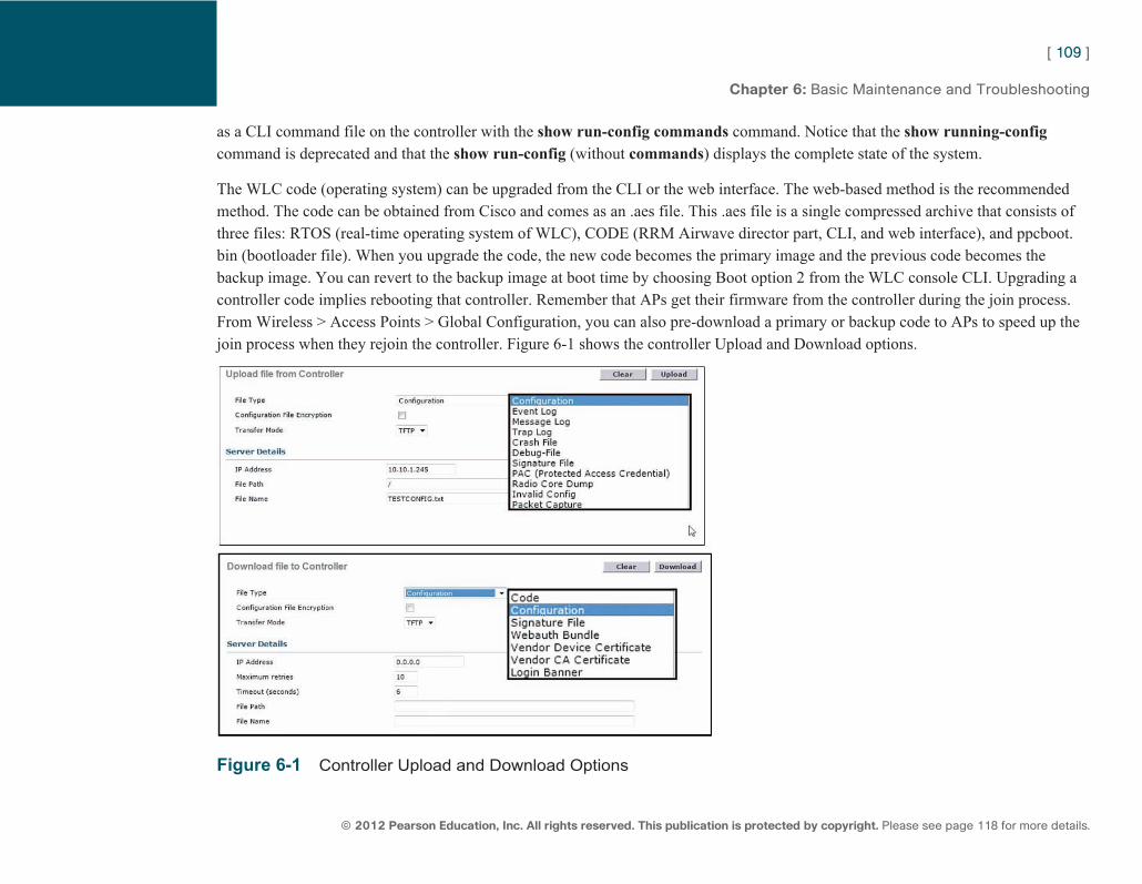
ptg7913109
[ 109 ]
© 2012 Pearson Education, Inc. All rights reserved. This publication is protected by copyright. Please see page 118 for more details.
Chapter 6: Basic Maintenance and Troubleshooting
as a CLI command file on the controller with the show run-config commands command. Notice that the show running-config command is deprecated and that the show run-config (without commands ) displays the complete state of the system.
The WLC code (operating system) can be upgraded from the CLI or the web interface. The web-based method is the recommended method. The code can be obtained from Cisco and comes as an .aes file. This .aes file is a single compressed archive that consists of three files: RTOS (real-time operating system of WLC), CODE (RRM Airwave director part, CLI, and web interface), and ppcboot.bin (bootloader file). When you upgrade the code, the new code becomes the primary image and the previous code becomes the backup image. You can revert to the backup image at boot time by choosing Boot option 2 from the WLC console CLI. Upgrading a controller code implies rebooting that controller. Remember that APs get their firmware from the controller during the join process. From Wireless > Access Points > Global Configuration, you can also pre-download a primary or backup code to APs to speed up the join process when they rejoin the controller. Figure 6-1 shows the controller Upload and Download options.
Figure 6-1 Controller Upload and Download Options
ptg7913109
[ 110 ]
© 2012 Pearson Education, Inc. All rights reserved. This publication is protected by copyright. Please see page 118 for more details.
Chapter 6: Basic Maintenance and Troubleshooting
You can reset a controller to its factory default from the Commands > Reset to Factory Default page. Clicking Reset deletes the config saved in NVRAM (but does not delete the config still present in RAM). You can then navigate to Commands > Reboot and choose Reboot Without Save to clear the controller configuration completely. You can also plan for a reboot in the future from the Commands > Schedule Reboot page, where you enter the time and date when the reboot should occur.
From Wireless > All APs, you can select an AP and click Clear All Config to remove all configured items specific to this AP. You can also click Clear All Config Except Static IP to keep the AP configured static IP address. Clicking Reset AP simply power-cycles the AP.
WLC and APs Management Access Methods The Cisco WLC has various management Access methods. These include the following:
■ Serial port access and telnet/SSH to the WLC Management interface IP address (CLI only). Note that terminal monitor is enabled by default on the Cisco WLC. SSH is enabled by default, and telnet is disabled by default.
■ HTTP-HTTPS access to the WLC Management interface IP address or service port IP address (5508, 4400, WiSM, WiSM2). HTTP is disabled by default (HTTPS is enabled by default).
■ Wireless client access. You can monitor and configure Cisco WLCs using a wireless client. This feature is supported for all management tasks except uploads from and downloads to the Cisco WLC. Before you can open the GUI or the CLI from a wireless client device, you must configure the Cisco WLC to allow the connection from the Management > Mgmt via Wireless page.
You can enable or disable HTTP or HTTPS from Management > HTTP-HTTPS and enable or disable Telnet or SSH from Management Telnet-SSH.
You can access the CAPWAP AP CLI from the AP console port. Once the AP has joined a controller, you can choose to allow Telnet or SSH to the AP IP address (disabled by default) from the AP Advanced configuration tab on the controller web interface. From the AP Credentials tab, you can choose to override the AP default credentials (Cisco/Cisco) and create new telnet/SSH credentials and a new enable password for the AP.
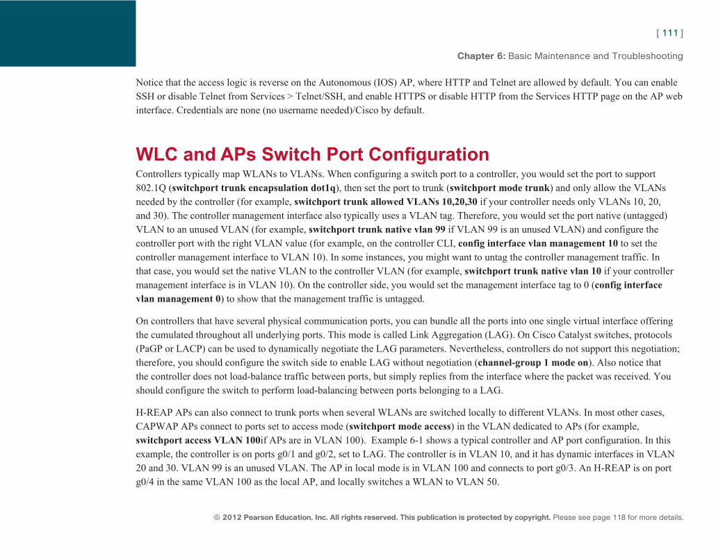
ptg7913109
[ 111 ]
© 2012 Pearson Education, Inc. All rights reserved. This publication is protected by copyright. Please see page 118 for more details.
Chapter 6: Basic Maintenance and Troubleshooting
Notice that the access logic is reverse on the Autonomous (IOS) AP, where HTTP and Telnet are allowed by default. You can enable SSH or disable Telnet from Services > Telnet/SSH, and enable HTTPS or disable HTTP from the Services HTTP page on the AP web interface. Credentials are none (no username needed)/Cisco by default.
WLC and APs Switch Port Configuration Controllers typically map WLANs to VLANs. When configuring a switch port to a controller, you would set the port to support 802.1Q ( switchport trunk encapsulation dot1q ), then set the port to trunk ( switchport mode trunk ) and only allow the VLANs needed by the controller (for example, switchport trunk allowed VLANs 10,20,30 if your controller needs only VLANs 10, 20, and 30). The controller management interface also typically uses a VLAN tag. Therefore, you would set the port native (untagged) VLAN to an unused VLAN (for example, switchport trunk native vlan 99 if VLAN 99 is an unused VLAN) and configure the controller port with the right VLAN value (for example, on the controller CLI, config interface vlan management 10 to set the controller management interface to VLAN 10). In some instances, you might want to untag the controller management traffic. In that case, you would set the native VLAN to the controller VLAN (for example, switchport trunk native vlan 10 if your controller management interface is in VLAN 10). On the controller side, you would set the management interface tag to 0 ( config interface vlan management 0 ) to show that the management traffic is untagged.
On controllers that have several physical communication ports, you can bundle all the ports into one single virtual interface offering the cumulated throughout all underlying ports. This mode is called Link Aggregation (LAG). On Cisco Catalyst switches, protocols (PaGP or LACP) can be used to dynamically negotiate the LAG parameters. Nevertheless, controllers do not support this negotiation; therefore, you should configure the switch side to enable LAG without negotiation ( channel-group 1 mode on ). Also notice that the controller does not load-balance traffic between ports, but simply replies from the interface where the packet was received. You should configure the switch to perform load-balancing between ports belonging to a LAG.
H-REAP APs can also connect to trunk ports when several WLANs are switched locally to different VLANs. In most other cases, CAPWAP APs connect to ports set to access mode ( switchport mode access ) in the VLAN dedicated to APs (for example, switchport access VLAN 100 if APs are in VLAN 100). Example 6-1 shows a typical controller and AP port configuration. In this example, the controller is on ports g0/1 and g0/2, set to LAG. The controller is in VLAN 10, and it has dynamic interfaces in VLAN 20 and 30. VLAN 99 is an unused VLAN. The AP in local mode is in VLAN 100 and connects to port g0/3. An H-REAP is on port g0/4 in the same VLAN 100 as the local AP, and locally switches a WLAN to VLAN 50.
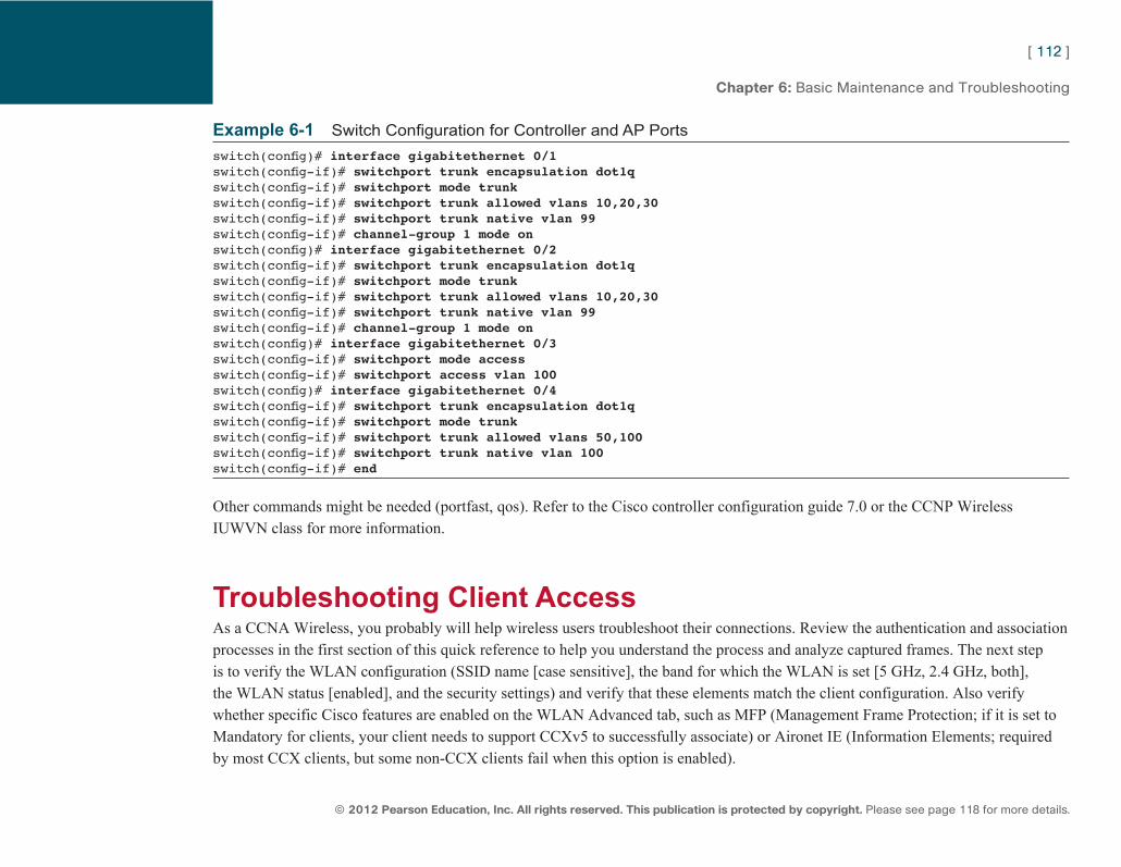
ptg7913109
[ 112 ]
© 2012 Pearson Education, Inc. All rights reserved. This publication is protected by copyright. Please see page 118 for more details.
Chapter 6: Basic Maintenance and Troubleshooting
Example 6-1 Switch Configuration for Controller and AP Ports switch(config) # interface gigabitethernet 0/1switch(config-if) # switchport trunk encapsulation dot1qswitch(config-if) # switchport mode trunkswitch(config-if) # switchport trunk allowed vlans 10,20,30switch(config-if) # switchport trunk native vlan 99switch(config-if) # channel-group 1 mode on switch(config) # interface gigabitethernet 0/2switch(config-if) # switchport trunk encapsulation dot1qswitch(config-if) # switchport mode trunkswitch(config-if) # switchport trunk allowed vlans 10,20,30switch(config-if) # switchport trunk native vlan 99switch(config-if) # channel-group 1 mode on switch(config) # interface gigabitethernet 0/3switch(config-if) # switchport mode accessswitch(config-if) # switchport access vlan 100switch(config) # interface gigabitethernet 0/4switch(config-if) # switchport trunk encapsulation dot1qswitch(config-if) # switchport mode trunkswitch(config-if) # switchport trunk allowed vlans 50,100switch(config-if) # switchport trunk native vlan 100switch(config-if) # end
Other commands might be needed (portfast, qos). Refer to the Cisco controller configuration guide 7.0 or the CCNP Wireless IUWVN class for more information.
Troubleshooting Client Access As a CCNA Wireless, you probably will help wireless users troubleshoot their connections. Review the authentication and association processes in the first section of this quick reference to help you understand the process and analyze captured frames. The next step is to verify the WLAN configuration (SSID name [case sensitive], the band for which the WLAN is set [5 GHz, 2.4 GHz, both], the WLAN status [enabled], and the security settings) and verify that these elements match the client configuration. Also verify whether specific Cisco features are enabled on the WLAN Advanced tab, such as MFP (Management Frame Protection; if it is set to Mandatory for clients, your client needs to support CCXv5 to successfully associate) or Aironet IE (Information Elements; required by most CCX clients, but some non-CCX clients fail when this option is enabled).
ptg7913109
[ 113 ]
© 2012 Pearson Education, Inc. All rights reserved. This publication is protected by copyright. Please see page 118 for more details.
Chapter 6: Basic Maintenance and Troubleshooting
Also remember that on the Cisco WLC, there is an option to manually disable the clients (from Security > Disabled Clients). You might want to verify whether the client MAC address is not listed on this page.
Finally, verify the environment to check for hidden node issues (where two clients on opposite sides of the cell do not hear each other and send frames at the same time, thus creating collision issues at the AP level) or exposed node issues (where neighboring clients send at the same time frames to different neighboring APs on the same channel, thus creating collision issues).
If the client associates properly but fails to get an IP address, keep in mind that the WLC acts as a DHCP relay, sending a query to the DHCP server IP address defined for the dynamic interface associated to the WLAN. If you use the controller internal DHCP server, the DHCP server IP address mentioned in the dynamic interface must be the controller management IP address. In all cases, the DHCP server address does not appear directly to the client. The client sees instead the controller virtual gateway IP address for the DHCP server IP address (unless DHCP proxy is disabled from the controller CLI).
If the issue is related to performances, you might want to check for backward compatibility issues. Remember that when an 802.11b client is detected, 802.11g clients must use protection (RTS/CTS). This typically results in sudden drops in the overall cell throughput.
If you think that the issue might be related to the wireless infrastructure, start by checking the physical connections (cables to the APs, to the controller, and port LED status). In a Cisco Unified environment, the WLC assumes the central role of managing the entire wireless network. CAPWAP APs, which serve the wireless clients, register themselves to the Cisco WLC and download the entire configuration from Cisco WLC. A troubleshooting step is also employed to check whether the AP your client attempts to use is registered to the Cisco WLC from the Wireless > All APs page. The client cannot connect without an AP.
The controller offers a view on any detected client (even probing, non-associated clients) from Monitor > Clients. You can then click any detected client to get a more detailed page for this client, such as WLAN, signal level (RSSI/SNR), and connection status). You can also get the same information from the CLI, with the show client summary command (lists clients), and the show client detail <client MAC address> .
The debug mac-address <MAC address> command is also very useful for following a specific client association exchange from the controller CLI. A common command combination is also to use debug dot11 state enable and debug dhcp packet enable to see whether the client passes the authentication, then the association state, then can communicate at Layer 3 (with DHCP exchanges) with the wired infrastructure.
ptg7913109
[ 114 ]
© 2012 Pearson Education, Inc. All rights reserved. This publication is protected by copyright. Please see page 118 for more details.
Chapter 6: Basic Maintenance and Troubleshooting
You can monitor the APs dialog with the controller using the debug capwap family of commands. The show ap config 802.11a|802.11b <AP MAC> command can also help you see the exact configuration of the AP your client is trying to use.
Beyond the many debug and show commands available on the controller, you may have to use third-party tools, such as packet sniffers (applications that enable a wireless card to capture all frames in a given channel and display them in order; this is very useful in running a per packet analysis and visualizing what packets are actually exchanged), spectrum analyzers (such as Cisco Spectrum Expert, to see the spectrum at Layer 1 and detect interferers), analyzers (such as AirMagnet Wi-Fi Analyzer, a hybrid tool with spectrum analyzer, packet capture, and network analysis capabilities), or site survey mapping tools (such as Ekahau Site Survey, to see what SSID, at what signal level, is seen in which area of the floor you want to troubleshoot).
Troubleshooting with WCS Both the Cisco WCS and Cisco WLCs keep track of important events. Using logs is often useful to troubleshoot connections. Choose WCS Home to access the summary pages. This page provides a top-level description of your network and included information about Cisco WLCs, coverage areas, access points, and clients. You also might want to check the alarm dashboard for elements that might prevent the network from performing optimally. WCS also enables you to monitor clients. In the client details page on Cisco WCS, you can check the same parameters as on the controller (client signal levels, status, SSID, and so on).
Cisco WCS can be used to troubleshoot client-related issues in a wireless environment. It does this with the help of the Troubleshooting tool, accessible from the Monitor > Clients page. You can then click a client MAC address to access a page with detailed information about the client. You can also troubleshoot a client connection by entering the client MAC address in the Troubleshoot field and clicking Troubleshoot . The Cisco WCS analyzes the client connection status and displays the result. If the connection problem is permanent (the issue is not an intermittent disconnection, which might reveal an RF-related issue), the window displays the most likely reason for the issue or the step at which it occurred.
The Cisco WCS client troubleshooting tool also offers a feature to track the logs relevant to a specific client. This is useful in reproducing an issue with a client. To use this tool, from the Client Troubleshooting page, click the Log Analysis tab, click Start to initiate the log, and then ask the client to try to reassociate. The WCS instructs the WLC to monitor each step of the client association and authentication processes and displays the progression and result of each phase in the window. The different elements are
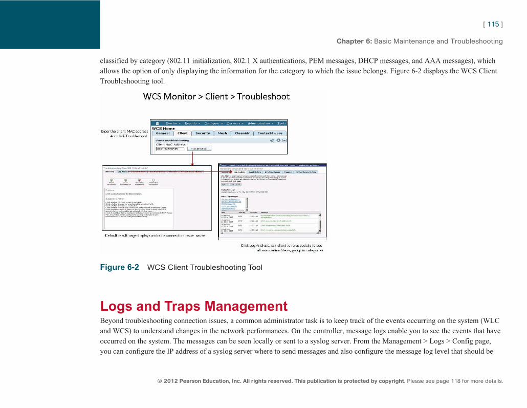
ptg7913109
[ 115 ]
© 2012 Pearson Education, Inc. All rights reserved. This publication is protected by copyright. Please see page 118 for more details.
Chapter 6: Basic Maintenance and Troubleshooting
classified by category (802.11 initialization, 802.1 X authentications, PEM messages, DHCP messages, and AAA messages), which allows the option of only displaying the information for the category to which the issue belongs. Figure 6-2 displays the WCS Client Troubleshooting tool.
Figure 6-2 WCS Client Troubleshooting Tool
Logs and Traps Management Beyond troubleshooting connection issues, a common administrator task is to keep track of the events occurring on the system (WLC and WCS) to understand changes in the network performances. On the controller, message logs enable you to see the events that have occurred on the system. The messages can be seen locally or sent to a syslog server. From the Management > Logs > Config page, you can configure the IP address of a syslog server where to send messages and also configure the message log level that should be
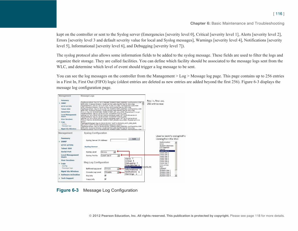
ptg7913109
[ 116 ]
© 2012 Pearson Education, Inc. All rights reserved. This publication is protected by copyright. Please see page 118 for more details.
Chapter 6: Basic Maintenance and Troubleshooting
kept on the controller or sent to the Syslog server (Emergencies [severity level 0], Critical [severity level 1], Alerts [severity level 2], Errors [severity level 3 and default severity value for local and Syslog messages], Warnings [severity level 4], Notifications [severity level 5], Informational [severity level 6], and Debugging [severity level 7]).
The syslog protocol also allows some information fields to be added to the syslog message. These fields are used to filter the logs and organize their storage. They are called facilities. You can define which facility should be associated to the message logs sent from the WLC, and determine which level of event should trigger a log message to be sent.
You can see the log messages on the controller from the Management > Log > Message log page. This page contains up to 256 entries in a First In, First Out (FIFO) logic (oldest entries are deleted as new entries are added beyond the first 256). Figure 6-3 displays the message log configuration page.
Figure 6-3 Message Log Configuration
ptg7913109
[ 117 ]
© 2012 Pearson Education, Inc. All rights reserved. This publication is protected by copyright. Please see page 118 for more details.
Chapter 6: Basic Maintenance and Troubleshooting
The controller also uses SNMP. This protocol is used to see the status of the WLC and control it from WCS or another SNMP-enabled remote management station. SNMPv1 and SNMPv2c are based on communities. Some communities are used to read the WLC parameters, and others are used to write to the WLC. Two default communities are defined on the WLC: public, for read access, and private, for write access. Because these communities are well-known values, they should be changed from Management > SNMP > Communities. You can also restrict the IP address range (with a 255.255.255.255 to point to only one IP address) of the management stations allowed to use each community to communicate with the WLC. The controller also supports SNMPv3, which uses username and password. A default username is also defined on the controller and should be changed from Management > SNMP > SNMPv3 Users.
WCS is automatically added as an SNMP trap receiver when you add a controller to WCS. You can add other SNMP trap receivers if needed, from Management > Trap Receivers. From Management > SNMP > Trap Controls, you can select which traps should be sent to all receivers.
You also can see the SNMP trap messages on the controller, from Management > SNMP > Trap Logs. Just like for the system messages, this page contains up to 256 entries in a FIFO logic.
From Management > Tech Support, you can access useful information, such as controller crash files or AP crash logs (which logs the reasons for the crash). These files are usually transmitted to advanced tech support or TAC but usually not managed directly by Wireless CCNAs.
ptg7913109
[ 118 ]
© 2012 Cisco Systems, Inc. All rights reserved. This publication is protected by copyright.
CCNA Wireless (640-722 IUWNE) Quick Reference
CCNA Wireless (640-722 IUWNE) Quick Reference Jerome Henry
Copyright© 2012 Cisco Systems, Inc.
Published by:Cisco Press800 East 96th StreetIndianapolis, IN 46240 USA
All rights reserved. No part of this ebook shall be reproduced, stored in a retrieval system, or transmitted by any means, electronic, mechanical, photocopying, recording, or otherwise, without written permission from the publisher. No patent liability is assumed with respect to the use of the information contained herein. Although every precaution has been taken in the preparation of this book, the publisher and author assume no responsibility for errors or omissions. Nor is any liability assumed for damages resulting from the use of the information contained herein.
First Release: April 2012
ISBN-10: 1-58714-308-9
ISBN-13: 978-1-58714-308-3
Warning and Disclaimer This book is designed to provide information about CCNA Wireless. Every effort has been made to make this book as complete and as accurate as possible, but no warranty or fitness is implied.
The information is provided on an “as is” basis. The authors, Cisco Press, and Cisco Systems, Inc. shall have neither liability nor responsibility to any person or entity with respect to any loss or damages arising from the information contained in this ebook or from the use of the discs or programs that may accompany it.
The opinions expressed in this ebook belong to the authors and are not necessarily those of Cisco Systems, Inc.
Trademark Acknowledgments All terms mentioned in this book that are known to be trademarks or service marks have been appropriately capitalized. Cisco Press or Cisco Systems, Inc. cannot attest to the accuracy of this information. Use of a term in this book should not be regarded as affecting the validity of any trademark or service mark.
Feedback Information At Cisco Press, our goal is to create in-depth technical books of the highest quality and value. Each book is crafted with care and precision, undergoing rigorous development that involves the unique expertise of members from the professional technical community.
Readers’ feedback is a natural continuation of this process. If you have any comments regarding how we could improve the quality of this book, or otherwise alter it to better suit your needs, you can contact us through email at [email protected] . Please make sure to include the book title and ISBN in your message.
We greatly appreciate your assistance.
Corporate and Government Sales Cisco Press offers excellent discounts on this book when ordered in quantity for bulk purchases or special-sales. For more information, please contact:
U.S. Corporate and Government Sales 1-800-382-3419 [email protected]
For sales outside the United States, please contact:
International Sales [email protected]