Embed Size (px)
Citation preview

OWNER'S MANUAL
YAMAHA Robot ControllerMRCH/QRCH/QRCX Series
UNIT

S-1
Safety Precautions(Always read before starting use)
Always read this manual, the robot controller instruction manual and programming manualbefore using this product. Take special care to safety, and correctly handle the product.The cautions given in this manual are related to this product. Refer to the robot controllerinstruction manual for details on the cautions to be taken with the robot controller sys-tem using this product.* The safety precautions are ranked as “WARNING” and “CAUTION” in this manual.
WARNINGFailure to follow WARNING instructions could result in serious injury ordeath to the operator or person servicing the product.
! CAUTIONFailure to follow CAUTION instructions may result in injury to the operator orperson servicing product, or damage to the product or peripheral equipment.
Note that some items described as “CAUTION” may lead to serious results dependingon the situation. In any case, important information that must be observed is explained.Store this manual where it can be easily referred to, and make sure that it is delivered tothe end user.
CC-Link is a registered trademark of Mitsubishi Electric Corporation Co., Ltd.The CC-Link compatible module provided with a label is compatible withCC-Link Ver 1.10.
[Precautions for design]
WARNING• Refer to the CC-Link system Master Module User's Manual and this
manual for details on the state of the CC-Link system and robot control-ler when a communication error occurs with the CC-Link system, etc.Configure an interlock circuit in the sequence program so that the sys-tem, including the robot controller will work safely using the communi-cation status information.
• This CC-Link compatible module has an emergency stop terminal to setthe robot controller in the emergency stop state. Prepare a physicalinterlock circuit so that the system, including the robot controller willwork safety, using this terminal.
! CAUTION
• The control line and communication cable must not be bound with or placednear the main circuit or power line. Separate these by at least 100mm.Failure to observe this could lead to malfunctions caused by noise.

S-2
[Precautions for installation]
WARNING• Always crimp, press-fit or solder the connector wire connections with
the maker-designated tool, and securely connect the connector to themodule.
• Always shut off all phases of the power supply externally before start-ing installation or wiring work.Failure to shut off all phases could lead to electric shocks or productdamage.
! CAUTION
• Use the robot controller within the environment specifications given in the manual.Use in an environment outside the environment specification range could lead toelectric shocks, fires, malfunctioning, product damage or deterioration.
• Mount the CC-Link compatible module on the back of the robot controller, andsecurely fix with screws.
• Never directly touch the conductive sections or electronic parts other than therotary switch on the CC-Link compatible module.
• Never directly touch the conductive sections or electric parts other than the DIPswitch on the CPU board.
• Accurately connect each connection cable connector to the mounting section.Failure to observe this could lead to malfunctions caused by a connection fault.

S-3
[Precautions for wiring]
WARNING• Always shut off all phases of the power supply externally before start-
ing installation or wiring work.Failure to shut off all phases could lead to electric shocks or productdamage.
• Always install the terminal covers enclosed with the product before turn-ing ON the power or operating the product after installation or wiringwork.Failure to install the terminal cover could lead to malfunctions.
! CAUTION
• Tighten the terminal screws within the specified torque range.A loose terminal screw could lead to short-circuiting or malfunctioning.If the terminal screw is too tight, short-circuiting or malfunctioning could occurdue to screw damage.
• Make sure that foreign matter, such as cutting chips or wire scraps, do not enterthe robot controller.
• The communication cables connected to the CC-Link compatible module mustbe placed in a conduit or fixed with a clamp.If the cable is not placed in a conduit or fixed with a clamp, the module or cablecould be damaged by the cable shifting, movement or unintentional pulling lead-ing to malfunctioning caused by an improper cable connection.
• Do not disconnect the communication cable connected to the CC-Link compat-ible module by pulling on the cable section.Loosen the screws on the connector, and then disconnect the cable.Pulling on the cable fixed with screws could lead to module or cable damage, ormalfunctioning caused by an improper cable connection.

S-4
[Precautions for starting and maintenance]
WARNING• Do not touch the terminals while the power is ON.
Failure to observe this could lead to malfunctioning.• Always shut off all phases of the power supply externally before clean-
ing or tightening the terminal screws.Failure to shut off all phases could lead to electric shocks, product dam-age or malfunctioning.A loose screw could lead to dropping, short-circuiting or malfunction-ing.If the screw is too tight, short-circuiting or malfunctioning could occurdue to screw damage.
• Never disassemble or modify any of the robot controller modules.Failure to observe this could lead to trouble, malfunctioning, injuries orfires.
• Always shut off all phases of the power supply externally before install-ing or removing the CC-Link compatible module.Failure to shut off all phases could lead to robot controller trouble ormalfunctioning.
• When using the robot controller with the CC-Link compatible modulemounted, always mount the enclosed ferrite core for noise measureson the power cable as close to the robot controller as possible.Failure to mount this ferrite core could lead to malfunctioning causedby noise.
[Precautions for disposal]
! CAUTION
• Dispose of this product as industrial waste.
Date of revision June 1999March 2001
Details of revisionsFirst editionSecond edition for compliance to V1.10
Revision history
This manual does not guarantee the implementation of industrial rights or otherrights, and does not authorize the implementation rights. YAMAHA shall not beheld liable for any problems regarding industrial rights that occur through the useof the contents given in this manual.
2001 YAMAHA MOTOR CO., LTD.

S-5
Introduction
Thank you for purchasing the CC-Link compatible module. This CC-Link compatiblemodule is an option module that enables connection of the YAMAHA robot controllerQRCX/QRCH and MRCH Series as a CC-Link system remote device station.The CC-Link compatible module with label is compatible with CC-Link Ver.1.10. CC-Link compatible modules without the CC-Link label are compatible with Ver.1.00.The robot controller explained in this manual refers to the QRCX/QRCH and MRCHSeries.This manual describes the flow of operations from wiring the CC-Link compatible mod-ule to programming, and includes setting examples.
For details on other devices such as connecting the master station PLC and PLC pro-gramming, refer to the manual for the respective product.Refer to the manual enclosed with the YAMAHA controller for details on operating therobot controller and on the robot program.

S-6
MEMO

C o n t e n t sC o n t e n t s
Chapter 1 Outline ................................................................ 1-11-1 Features ..........................................................................................1-31-2 Mechanism ......................................................................................1-41-3 Names of each part on the CC-Link compatible module.................1-51-4 Assignment of CC-Link compatible I/O ...........................................1-61-5 Shift of CC-Link system connection status and robot controller status ...... 1-7
Chapter 2 Connection......................................................... 2-12-1 Confirming the CC-Link compatible module settings ......................2-32-2 Setting the CC-Link compatible module ..........................................2-4
2-2-1 Removing the CC-Link compatible module .................................. 2-42-2-2 Setting the station No. ..................................................................2-52-2-3 Setting the communication baud rate .......................................... 2-62-2-4 Installing the CC-Link compatible module .................................... 2-7
2-3 Setting to the CC-Link system specification controller ....................2-82-3-1 Removing the standard I/O module ............................................. 2-82-3-2 Installing the CC-Link compatible module .................................... 2-92-3-3 Changing the robot controller DIP switch ................................... 2-10
2-4 Noise measures ............................................................................2-122-4-1 Mounting the ferrite core ............................................................2-12
2-5 Connecting to the CC-Link system................................................2-132-5-1 Connecting to the cable terminal to the controller ...................... 2-132-5-2 Testing the line from the master station PLC ............................. 2-14
2-6 Connecting the emergency stop terminal ......................................2-15
Chapter 3 Communication ................................................. 3-13-1 State when robot controller power is turned ON .............................3-33-2 Initial process for connecting to CC-Link system ............................3-4
3-2-1 Initial data process ....................................................................... 3-43-3 Communication with master station PLC ........................................3-5
3-3-1 Receiving data ............................................................................. 3-53-3-2 Transmitting data .........................................................................3-6
3-4 Direct connection by emulated serialization on parallel DIO ...........3-73-4-1 Setting from teaching box ............................................................ 3-7
3-5 Referring to communication data ....................................................3-93-5-1 Referring to the data from the teaching box ................................. 3-9
Chapter 4 Troubleshooting ................................................ 4-14-1 Items to confirm before starting up CC-Link system .......................4-34-2 Meanings of LEDs on CC-Link compatible module.........................4-44-3 Troubleshooting...............................................................................4-5
4-3-1 Robot controller front panel LED confirmation ............................. 4-54-3-2 Teaching box error display confirmation ...................................... 4-64-3-3 CC-Link compatible module LED confirmation ............................ 4-74-3-4 Confirmation from master station PLC .........................................4-7

Chapter 5 Appendix ............................................................ 5-15-1 Profile ..............................................................................................5-35-2 Details of remote input/output signals .............................................5-55-3 Dedicated input/output signal timing chart ......................................5-7
5-3-1 Initial data process for CC-Link connection .................................5-75-3-2 Servo ON and emergency stop .................................................... 5-85-3-3 Origin return (Valid when incremental motor is connected) ......... 5-95-3-4 Automatic mode changeover, program reset and program execution .. 5-105-3-5 Stopping with program interlock ................................................. 5-11
5-4 Sample program............................................................................5-125-5 CC-Link compatible module specifications ...................................5-19

MEMO

CHAPTER1234567890123456789012345678901212345678901234567890123456789012123456789012345678901234567890123456789012345678901234567890121234567890123456789012345678901212345678901234567890123456789012345678901234567890123456789012123456789012345678901234567890121234567890123456789012345678901234567890123456789012345678901212345678901234567890123456789012123456789012345678901234567890123456789012345678901234567890121234567890123456789012345678901212345678901234567890123456789012345678901234567890123456789012123456789012345678901234567890121234567890123456789012345678901234567890123456789012345678901212345678901234567890123456789012123456789012345678901234567890123456789012345678901234567890121234567890123456789012345678901212345678901234567890123456789011
Outline
1-1 Features ..........................................................................................1-3
1-2 Mechanism ......................................................................................1-4
1-3 Names of each part on the CC-Link compatible module.................1-5
1-4 Assignment of CC-Link compatible I/O ...........................................1-6
1-5 Shift of CC-Link system connection status and robot controller status ...... 1-7

1-2
MEMO
1-3
CHAPTER1 Outline
1-1 Features
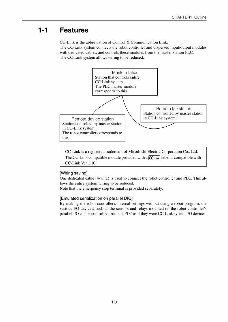
CC-Link is the abbreviation of Control & Communication Link.The CC-Link system connects the robot controller and dispersed input/output moduleswith dedicated cables, and controls these modules from the master station PLC.The CC-Link system allows wiring to be reduced.
Master stationStation that controls entire CC-Link system.The PLC master module corresponds to this.
Remote device stationStation controlled by master station in CC-Link system.The robot controller corresponds to this.
Remote I/O stationStation controlled by master station in CC-Link system.
CC-Link is a registered trademark of Mitsubishi Electric Corporation Co., Ltd.The CC-Link compatible module provided with a label is compatible withCC-Link Ver 1.10.
[Wiring saving]One dedicated cable (4-wire) is used to connect the robot controller and PLC. This al-lows the entire system wiring to be reduced.Note that the emergency stop terminal is provided separately.
[Emulated serialization on parallel DIO]By making the robot controller's internal settings without using a robot program, thevarious I/O devices, such as the sensors and relays mounted on the robot controller'sparallel I/O can be controlled from the PLC as if they were CC-Link system I/O devices.
1-4
CHAPTER1 Outline
1-2 Mechanism
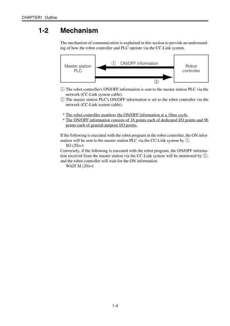
The mechanism of communication is explained in this section to provide an understand-ing of how the robot controller and PLC operate via the CC-Link system.
q
w
ON/OFF informationMaster station
PLCRobot
controller
q The robot controller's ON/OFF information is sent to the master station PLC via thenetwork (CC-Link system cable).
w The master station PLC's ON/OFF information is set to the robot controller via thenetwork (CC-Link system cable).
* The robot controller monitors the ON/OFF information at a 10ms cycle.* The ON/OFF information consists of 16 points each of dedicated I/O points and 96
points each of general-purpose I/O points.
If the following is executed with the robot program in the robot controller, the ON infor-mation will be sent to the master station PLC via the CC-Link system by q.
SO (20)=1Conversely, if the following is executed with the robot program, the ON/OFF informa-tion received from the master station via the CC-Link system will be monitored by w,and the robot controller will wait for the ON information.
WAIT SI (20)=1

1-5
CHAPTER1 Outline
1-3 Names of each part on the CC-Link compatible module
The names of each part on the CC-Link compatible module mounted on the robot con-troller are described in this section. This module is mounted on the top back of the robotcontroller. The standard I/O module cannot be mounted in this case.
EMGIN CC-LINKEMG
MSB
LSB
BPS
GND RUN ERRL SD RD DA DB DG SLD
q
r
w e
t
y
Panel front
Panel front CC-Link
compatible board
Top view of CC-Link module
q Emergency stop terminalThis emergency stop terminal requires physical wiring separate from the emergencystop input on the CC-Link system. This must be short-circuited for the robot control-ler to operate correctly.Sequence this terminal with the safety fence, etc., used to protect the worker enteringthe robot's movement range, and ensure safety for the robot.
w Transmission monitor LEDThe status in the CC-Link system is indicated with ON, OFF and flickering status offour LEDs.
e CC-Link system cable terminalThis terminal is used to connect the CC-Link system cable. Each of the four terminalshas a meaning. Make sure not to incorrect wire these.
r Station No. setting switch (MSB: 10th place)This is the rotary switch for setting the robot controller station No. in the CC-Linksystem. The 10th place of the station No. is set with this switch.
t Station No. setting switch (LSB: 1st place)This is the rotary switch for setting the robot controller station No. in the CC-Linksystem. The 1st place of the station No. is set with this switch.
y Baud rate switch (BPS)This is the rotary switch for setting the CC-Link system's communication baud rate.

1-6
CHAPTER1 Outline
1-4 Assignment of CC-Link compatible I/O
The I/O expressions used in the robot controller's program language and the I/O expres-sions for the remote device stations differ. The correspondence is shown below.
RXn7 to RXn0
RXnF to RXn8
RX(n+1)7 to RX(n+1)0
RX(n+1)F to RX(n+1)8
RX(n+2)7 to RX(n+2)0
RX(n+2)F to RX(n+2)8
RX(n+3)7 to RX(n+3)0
RX(n+3)F to RX(n+3)8
RX(n+4)7 to RX(n+4)0
RX(n+4)F to RX(n+4)8
RX(n+5)7 to RX(n+5)0
RX(n+5)F to RX(n+5)8
RX(n+6)7 to RX(n+6)0
RX(n+6)F to RX(n+6)8
RX(n+7)F to RX(n+7)0*2
RWr0 to RWr31*3
SO0 (7 to 0)*1
SO1 (7 to 0)*1
SO2 (7 to 0)SO3 (7 to 0)SO4 (7 to 0)SO5 (7 to 0)SO6 (7 to 0)SO7 (7 to 0)SO10 (7 to 0)SO11 (7 to 0)SO12 (7 to 0)SO13 (7 to 0)SO14 (7 to 0)SO15 (7 to 0) ____ ____
RYn7 to RYn0
RYnF to RYn8
RY(n+1)7 to RY(n+1)0
RY(n+1)F to RY(n+1)8
RY(n+2)7 to RY(n+2)0
RY(n+2)F to RY(n+2)8
RY(n+3)7 to RY(n+3)0
RY(n+3)F to RY(n+3)8
RY(n+4)7 to RY(n+4)0
RY(n+4)F to RY(n+4)8
RY(n+5)7 to RY(n+5)0
RY(n+5)F to RY(n+5)8
RY(n+6)7 to RY(n+6)0
RY(n+6)F to RY(n+6)8
RY(n+7)F to RY(n+7)0*2
RWw0 to RWw31*3
SI0 (7 to 0)*1
SI1 (7 to 0)*1
SI2 (7 to 0)SI3 (7 to 0)SI4 (7 to 0)SI5 (7 to 0)SI6 (7 to 0)SI7 (7 to 0)SI10 (7 to 0)SI11 (7 to 0)SI12 (7 to 0)SI13 (7 to 0)SI14 (7 to 0)SI15 (7 to 0) ____ ____
Output from robot controller Input to robot controller Program language Remote device station Program language Remote device station
n: Address assigned to master module with station No. setting
Caution)*1: Has a meaning in the robot controller's internal process as a dedicated input/
output. This cannot be used as a general-purpose output in the robot program.*2: This area is reserved for the CC-Link system.*3: The remote registers are not currently supported.
An example of the flow of the I/O information in the robot controller (remote devicestation) is shown below. The buffer memory in the master station used to store the infor-mation, etc., differs according to the PLC type and station No., etc. Refer to the PLCManual for details.
X10F to X100
:
X17F to X170
E0hFROM
TO
:
E8h
RXnF to RXnO(SO1()/SO0())
:
RX(n+7)F to RX(n+7)0
RYnF to RYnO(SI1()/SI0())
:
RY(n+7)F to RY(n+7)0
Y10F to Y100
:
Y17F to Y170
160h
:
168h
PLC CPU(A1SHCPU)
Master station(A1SJ61BT11)
Remote input Remote input
Remote output Remote output
Robot controller
Automatic update
1-7
CHAPTER1 Outline
1-5 Shift of CC-Link system connection status androbot controller status
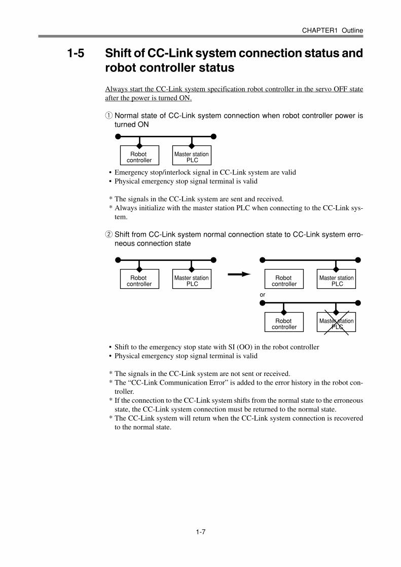
Always start the CC-Link system specification robot controller in the servo OFF stateafter the power is turned ON.
q Normal state of CC-Link system connection when robot controller power isturned ON
Robot controller
Master station PLC
• Emergency stop/interlock signal in CC-Link system are valid• Physical emergency stop signal terminal is valid
* The signals in the CC-Link system are sent and received.* Always initialize with the master station PLC when connecting to the CC-Link sys-
tem.
w Shift from CC-Link system normal connection state to CC-Link system erro-neous connection state
Robot controller
Master station PLC
Robot controller
Master station PLC
Robot controller
Master station PLC
or
• Shift to the emergency stop state with SI (OO) in the robot controller• Physical emergency stop signal terminal is valid
* The signals in the CC-Link system are not sent or received.* The “CC-Link Communication Error” is added to the error history in the robot con-
troller.* If the connection to the CC-Link system shifts from the normal state to the erroneous
state, the CC-Link system connection must be returned to the normal state.* The CC-Link system will return when the CC-Link system connection is recovered
to the normal state.
1-8
CHAPTER1 Outline
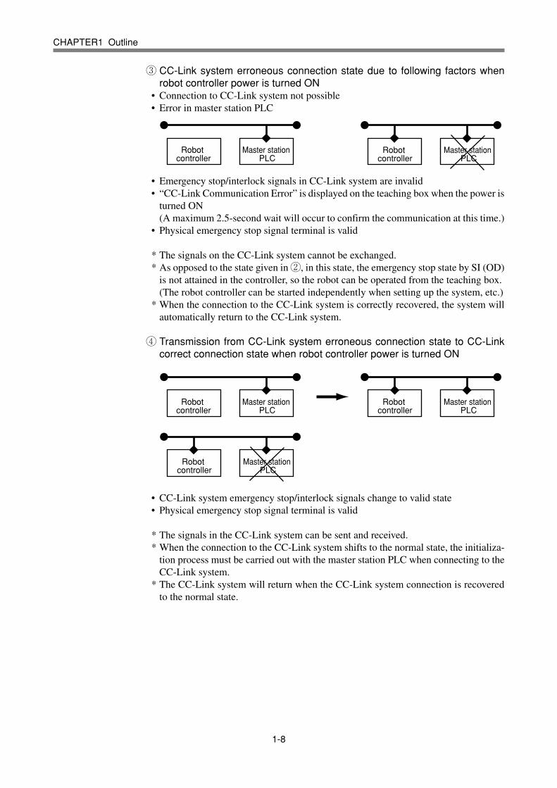
e CC-Link system erroneous connection state due to following factors whenrobot controller power is turned ON
• Connection to CC-Link system not possible• Error in master station PLC
Robot controller
Master station PLC
Robot controller
Master station PLC
• Emergency stop/interlock signals in CC-Link system are invalid• “CC-Link Communication Error” is displayed on the teaching box when the power is
turned ON(A maximum 2.5-second wait will occur to confirm the communication at this time.)
• Physical emergency stop signal terminal is valid
* The signals on the CC-Link system cannot be exchanged.* As opposed to the state given in w, in this state, the emergency stop state by SI (OD)
is not attained in the controller, so the robot can be operated from the teaching box.(The robot controller can be started independently when setting up the system, etc.)
* When the connection to the CC-Link system is correctly recovered, the system willautomatically return to the CC-Link system.
r Transmission from CC-Link system erroneous connection state to CC-Linkcorrect connection state when robot controller power is turned ON
Robot controller
Master station PLC
Robot controller
Master station PLC
Robot controller
Master station PLC
• CC-Link system emergency stop/interlock signals change to valid state• Physical emergency stop signal terminal is valid
* The signals in the CC-Link system can be sent and received.* When the connection to the CC-Link system shifts to the normal state, the initializa-
tion process must be carried out with the master station PLC when connecting to theCC-Link system.
* The CC-Link system will return when the CC-Link system connection is recoveredto the normal state.

CHAPTER1234567890123456789012345678901212345678901234567890123456789012123456789012345678901234567890123456789012345678901234567890121234567890123456789012345678901212345678901234567890123456789012345678901234567890123456789012123456789012345678901234567890121234567890123456789012345678901234567890123456789012345678901212345678901234567890123456789012123456789012345678901234567890123456789012345678901234567890121234567890123456789012345678901212345678901234567890123456789012345678901234567890123456789012123456789012345678901234567890121234567890123456789012345678901234567890123456789012345678901212345678901234567890123456789012123456789012345678901234567890123456789012345678901234567890121234567890123456789012345678901212345678901234567890123456789022
Connection
2-1 Confirming the CC-Link compatible module settings ......................2-3
2-2 Setting the CC-Link compatible module ..........................................2-4
2-2-1 Removing the CC-Link compatible module .................................. 2-42-2-2 Setting the station No. ..................................................................2-52-2-3 Setting the communication baud rate .......................................... 2-62-2-4 Installing the CC-Link compatible module .................................... 2-7
2-3 Setting to the CC-Link system specification controller ....................2-8
2-3-1 Removing the standard I/O module ............................................. 2-82-3-2 Installing the CC-Link compatible module .................................... 2-92-3-3 Changing the robot controller DIP switch ................................... 2-10
2-4 Noise measures ............................................................................2-12
2-4-1 Mounting the ferrite core ............................................................2-12
2-5 Connecting to the CC-Link system................................................2-13
2-5-1 Connecting to the cable terminal to the controller ...................... 2-132-5-2 Testing the line from the master station PLC ............................. 2-14
2-6 Connecting the emergency stop terminal ......................................2-15

2-2
MEMO
2-3
CHAPTER2 Connection
2-1 Confirming the CC-Link compatible module settings
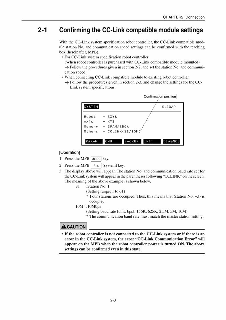
With the CC-Link system specification robot controller, the CC-Link compatible mod-ule station No. and communication speed settings can be confirmed with the teachingbox (hereinafter, MPB).
• For CC-Link system specification robot controller(When robot controller is purchased with CC-Link compatible module mounted)→ Follow the procedures given in section 2-2, and set the station No. and communi-cation speed.
• When connecting CC-Link compatible module to existing robot controller→ Follow the procedures given in section 2-3, and change the settings for the CC-
Link system specifications.
[Operation]1. Press the MPB MODE key.
2. Press the MPB F 5 (system) key.
3. The display above will appear. The station No. and communication baud rate set forthe CC-Link system will appear in the parentheses following “CCLINK” on the screen.The meaning of the above example is shown below.
S1 :Station No. 1(Setting range: 1 to 61)* Four stations are occupied. Thus, this means that (station No. +3) is
occupied.10M :10Mbps
(Setting baud rate [unit: bps]: 156K, 625K, 2.5M, 5M, 10M)* The communication baud rate must match the master station setting.
! CAUTION
• If the robot controller is not connected to the CC-Link system or if there is anerror in the CC-Link system, the error “CC-Link Communication Error” willappear on the MPB when the robot controller power is turned ON. The abovesettings can be confirmed even in this state.
SYSTEM 6.20AP
Robot = SXYt
Axis = XYZ
Memory = SRAM/256k
Others = CCLINK(S1/10M)
PARAM CMU BACKUP INIT DIAGNOS
Confirmation position

2-4
CHAPTER2 Connection
2-2 Setting the CC-Link compatible module
To connect the CC-Link system specification controller to the CC-Link system, the sta-tion No. and communication baud rate must be set with the rotary switch on the CC-Linkcompatible module. Confirm the current station No. and communication baud rate withthe procedures given in section 2-1.The operations given in section 2-3. are not required when this section is set.
2-2-1 Removing the CC-Link compatible module
Remove the CC-Link compatible module connected at the top back of the robot controller.
Power AC connector
Cooling fan
Driver module 1
CC-Link compatible module
Driver module 2
Expansion I/O module
Expansion output connectorExpansion input connector
PI connectorMOTOR connector
Controller serial No.
Example of back view when CC-Link compatible module is mounted on QRCH
[Procedures]1. Completely shut off the power input to the robot controller. Disconnect the I/O cable
if it is connected.2. Move the robot controller to a position where work can be carried out on the back
side.3. Using a Phillips head screwdriver, remove the two screws on both sides of the CC-
Link compatible module connected at the top back of the robot controller.4. Pull out the CC-Link compatible module in the direction parallel with the robot con-
troller grounding surface.
WARNING• Completely shut off the power supplied to the robot controller.
! CAUTION• Completely shut off the power supplied to the robot controller.• Always disconnect the cables connected to the CC-Link compatible module.• Carefully remove the CC-Link compatible module while taking care not to ap-
ply excessive force.• Never directly touch the conductive sections or electronic parts other than the
rotary switch on the CC-Link compatible module.• Do not apply impact on the CC-Link compatible module.• Do not place water or conductive matters, etc., which could cause damage near
the CC-Link compatible module.

2-5
CHAPTER2 Connection
2-2-2 Setting the station No.
Using the rotary switches MSB and LSB on the top of the CC-Link compatible module,set the station No. of the robot controller in the CC-Link system.
MSB
LSB
BPS
Top view of CC-Link compatible module
Panel surface
[Procedures]1. Confirm the station No. of the robot controller in the CC-Link system.
The station No. must be set between 1 and 61.* Up to 64 stations can be set as the CC-Link system, but as the CC-Link compatible
module occupies four stations, it will occupy (station No. +3). Thus, the abovesetting range applies.
2. Using a precision Phillips head screwdriver, set the 10th place digit of the station No.with rotary switch MSB.
3. In the same manner, set the 1st place digit with rotary switch LSB.
! CAUTION• Never directly touch the conductive sections or electronic parts other than the
rotary switch on the CC-Link compatible module.• Do not apply impact on the CC-Link compatible module.• Do not place water or conductive matters, etc., which could cause damage near
the CC-Link compatible module.• Accurately set the station No.• Make sure not to set the rotary switch BPS by mistake.

2-6
CHAPTER2 Connection
2-2-3 Setting the communication baud rate
Using the rotary switch BPS on the CC-Link compatible module, set the communicationbaud rate for the robot controller in the CC-Link system.
MSB
LSB
BPS
Top view of CC-Link compatible module
Panel surface
[Procedures]1. Confirm the communication baud rate for the robot controller in the CC-Link system.
The communication baud rate must be set between 156K and 10Mbps. The corre-spondence of the communication baud rate and switch is shown below.
156KBaud rate [bps]
Switch No. Other than left setting
625K 2.5M 5M 10M Error
0 1 2 3 4
2. Using a precision Phillips head screwdriver, set the switch No. corresponding to thecommunication baud rate with rotary switch BPS.* The communication baud rate must match the CC-Link system's master station
setting.
! CAUTION• Never directly touch the conductive sections or electronic parts other than the
rotary switch on the CC-Link compatible module.• Do not apply impact on the CC-Link compatible module.• Do not place water or conductive matters, etc., which could cause damage near
the CC-Link compatible module.• Accurately set the communication baud rate.• Make sure not to set the rotary switches MSB and LSB by mistake.

2-7
CHAPTER2 Connection
2-2-4 Installing the CC-Link compatible module
Install the CC-Link compatible module at the back top position of the robot controller.
Power AC connector
Cooling fan
Driver module 1
CC-Link compatible module
Driver module 2
Expansion I/O module
Expansion output connectorExpansion input connector
PI connectorMOTOR connector
Controller serial No.
Example of back view when CC-Link compatible module is mounted on QRCH
[Procedure]1. Completely shut off all power input to the robot controller.2. Move the robot controller to a position where work can be carried out on the back
side.3. If a CC-Link compatible module is connected, remove it with the procedure given in
section -1.4. Set the CC-Link compatible module at the back top position of the robot controller so
that it is parallel with the robot controller's grounding surface, and insert it along therails.
5. Using a Phillips head screwdriver, accurately fix the two screws on both sides of theinserted CC-Link compatible module.
6. Connect the CC-Link communication cable and emergency stop cable.
WARNING• Completely shut off the power supplied to the robot controller.
! CAUTION
• Always install the CC-Link compatible module with the connection cables dis-connected.
• Carefully remove the CC-Link compatible module while taking care not to ap-ply excessive force.
• Never directly touch the conductive sections or electronic parts other than therotary switch on the CC-Link compatible module.
• Do not apply impact on the CC-Link compatible module.• Do not place water or conductive matters, etc., which could cause damage near
the CC-Link compatible module.
2-8
CHAPTER2 Connection
2-3 Setting to the CC-Link system specification controller
When connecting the CC-Link compatible module to an existing robot controller, theCC-Link compatible module must be installed and the DIP switches in the robot control-ler must be changed. Confirm the CC-Link system specifications with the proceduregiven in section 2-1.This section is not required if section 2-2. has been carried out.
2-3-1 Removing the standard I/O module
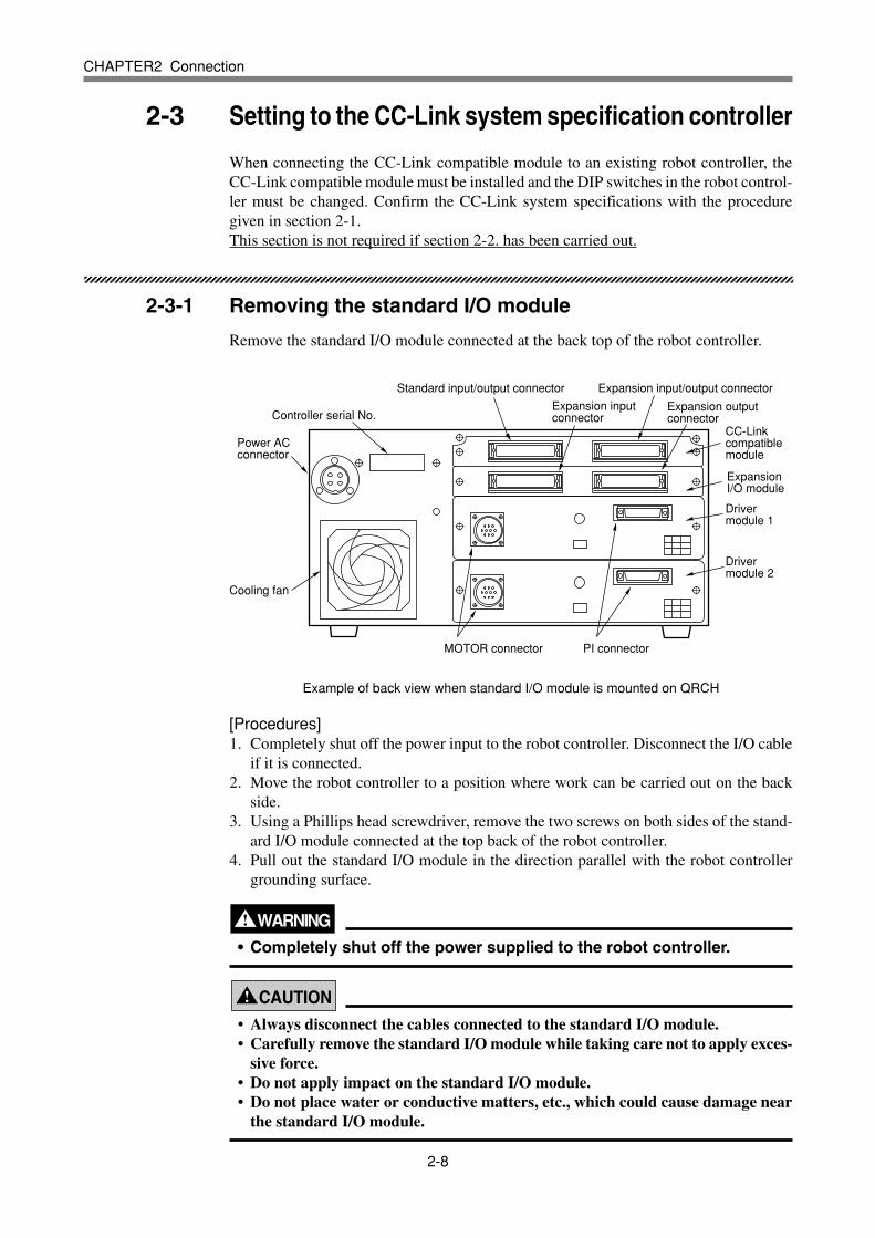
Remove the standard I/O module connected at the back top of the robot controller.
Standard input/output connector Expansion input/output connector
Power AC connector
Cooling fan
Driver module 1
CC-Link compatible module
Driver module 2
Expansion I/O module
Expansion output connector
Expansion input connector
PI connectorMOTOR connector
Controller serial No.
Example of back view when standard I/O module is mounted on QRCH
[Procedures]1. Completely shut off the power input to the robot controller. Disconnect the I/O cable
if it is connected.2. Move the robot controller to a position where work can be carried out on the back
side.3. Using a Phillips head screwdriver, remove the two screws on both sides of the stand-
ard I/O module connected at the top back of the robot controller.4. Pull out the standard I/O module in the direction parallel with the robot controller
grounding surface.
WARNING• Completely shut off the power supplied to the robot controller.
! CAUTION• Always disconnect the cables connected to the standard I/O module.• Carefully remove the standard I/O module while taking care not to apply exces-
sive force.• Do not apply impact on the standard I/O module.• Do not place water or conductive matters, etc., which could cause damage near
the standard I/O module.
2-9
CHAPTER2 Connection
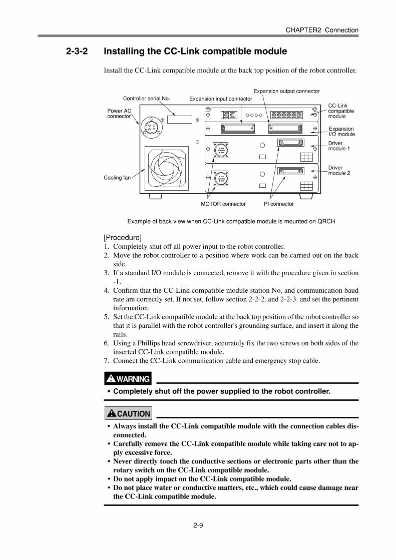
2-3-2 Installing the CC-Link compatible module
Install the CC-Link compatible module at the back top position of the robot controller.
Power AC connector
Cooling fan
Driver module 1
CC-Link compatible module
Driver module 2
Expansion I/O module
Expansion output connectorExpansion input connector
PI connectorMOTOR connector
Controller serial No.
Example of back view when CC-Link compatible module is mounted on QRCH
[Procedure]1. Completely shut off all power input to the robot controller.2. Move the robot controller to a position where work can be carried out on the back
side.3. If a standard I/O module is connected, remove it with the procedure given in section
-1.4. Confirm that the CC-Link compatible module station No. and communication baud
rate are correctly set. If not set, follow section 2-2-2. and 2-2-3. and set the pertinentinformation.
5. Set the CC-Link compatible module at the back top position of the robot controller sothat it is parallel with the robot controller's grounding surface, and insert it along therails.
6. Using a Phillips head screwdriver, accurately fix the two screws on both sides of theinserted CC-Link compatible module.
7. Connect the CC-Link communication cable and emergency stop cable.
WARNING• Completely shut off the power supplied to the robot controller.
! CAUTION
• Always install the CC-Link compatible module with the connection cables dis-connected.
• Carefully remove the CC-Link compatible module while taking care not to ap-ply excessive force.
• Never directly touch the conductive sections or electronic parts other than therotary switch on the CC-Link compatible module.
• Do not apply impact on the CC-Link compatible module.• Do not place water or conductive matters, etc., which could cause damage near
the CC-Link compatible module.
2-10
CHAPTER2 Connection
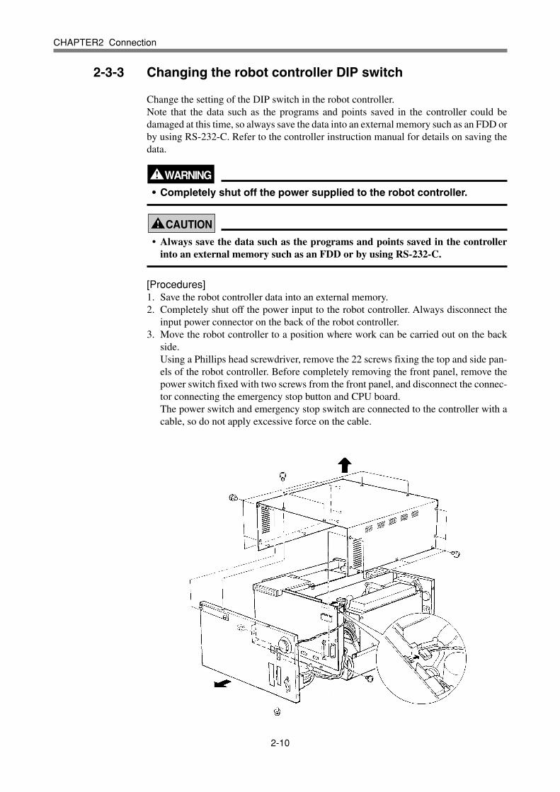
2-3-3 Changing the robot controller DIP switch
Change the setting of the DIP switch in the robot controller.Note that the data such as the programs and points saved in the controller could bedamaged at this time, so always save the data into an external memory such as an FDD orby using RS-232-C. Refer to the controller instruction manual for details on saving thedata.
WARNING• Completely shut off the power supplied to the robot controller.
! CAUTION
• Always save the data such as the programs and points saved in the controllerinto an external memory such as an FDD or by using RS-232-C.
[Procedures]1. Save the robot controller data into an external memory.2. Completely shut off the power input to the robot controller. Always disconnect the
input power connector on the back of the robot controller.3. Move the robot controller to a position where work can be carried out on the back
side.Using a Phillips head screwdriver, remove the 22 screws fixing the top and side pan-els of the robot controller. Before completely removing the front panel, remove thepower switch fixed with two screws from the front panel, and disconnect the connec-tor connecting the emergency stop button and CPU board.The power switch and emergency stop switch are connected to the controller with acable, so do not apply excessive force on the cable.

2-11
CHAPTER2 Connection
4. Set switch 6 of the DIP switch 2 on the CPU board to ON.
DIP switch 2
CPU boardSet to ON
5. Fix the power switch with two screws, and connect the connector for the emergencystop button.Install the top and front panels to the controller, and securely fix with the 22 screws.
6. Connect the input power connector on the back of the controller, and turn the powerON.
7. The following type of question will appear on the MPB screen, so answer as "YES".
8. If the controller does not operate properly because of a memory error, etc., load thedata saved in step 1. into the controller. Refer to the controller instruction manual fordetails on loading the data.If the robot controller is not correctly connected with the CC-Link system, the mes-sage "CC-Link Communication Error" will appear on the MPB.
! CAUTION
• Never directly touch the conductive sections or electric parts other than the DIPswitch on the CPU board.
• Do not apply impact on the CPU board.• Do not place water or conductive matters, etc., which could cause damage near
the CPU board.• If the robot controller is not connected to the CC-Link system or if there is an
error in the CC-Link system, the error "CC-Link Communication Error" willappear on the MPB when the robot controller power is turned ON.
• Always save the data such as the programs and points saved in the controllerinto an external memory such as an FDD or by using RS-232-C.
POWER
Warning! Dipswitch is changed
OLD status is = xxxxH
If not wanted, power down and reset
Go on OK? YES NO

2-12
CHAPTER2 Connection
2-4 Noise measures
A ferrite core must be mounted on the input power cable when connecting to the CC-Link system.
2-4-1 Mounting the ferrite core
Mount the ferrite core onto the input power cable connected to the input power connec-tor on the upper left back of the robot controller.
[Procedures]1. Mount the enclosed ferrite core onto the input power cable. The ferrite core should be
placed as close to the robot controller body as possible.2. Fix the mounted ferrite core with an Insulock tie, etc.
WARNING• Completely shut off the power supply to the input power cable before
starting this work.
! CAUTION
• Securely fix the ferrite core. If the ferrite core is not mounted, trouble couldoccur with the CC-Link system operations.

2-13
CHAPTER2 Connection
2-5 Connecting to the CC-Link system
The CC-Link system cable must be connected to the CC-Link compatible module inorder to connect to the CC-Link system.
2-5-1 Connecting to the cable terminal to the controller
Connect the CC-Link system cable to the C-Link system cable terminal on the right ofthe CC-Link compatible module.
Power AC connector
Cooling fan
Driver module 1
CC-Link compatible module
Driver module 2
Expansion I/O module
Expansion output connector
Expansion input connector
PI connectorMOTOR connector
Controller serial No.
CC-Link system cableterminal
Emergency stop terminal
Example of back view when CC-Link compatible module is mounted on QRCH
[Procedure]1. Using a Phillips head screwdriver, completely loosen the two screws on both sides of
the CC-Link system cable terminal, and remove the terminal block section from theCC-Link compatible module.
2. Using a Phillips head screwdriver, securely fix the CC-Link system cable to the ter-minal block removed in step 1.The names of each terminal on the cable terminal block are shown below.
DA DB DG SLD
* When connecting a terminator, connect it across DA-DB.
* A slit to prevent incorrect inverted insertion is provided on the cable terminal block.
Upward
3. Connect the cable terminal, into which the CC-Link system cable has been installed,to the CC-Link compatible module terminal block section on the robot controller,and completely fix with the two screws on both sides using a Phillips head screw-driver.
WARNING• Completely shut off the power supplied to the robot controller.
2-14
CHAPTER2 Connection
! CAUTION
• Always remove the terminal block section when installing the CC-Link systemcable.
• Securely fix the CC-Link system cable.• Carefully carry out the work to valid applying excessive force on the CC-Link
cable.• Treat each end of the C-Link system cable wire with a round terminal or Y
terminal so that it will not dislocate.• Carefully carry out the work so that the CC-Link system cable is not incorrectly
wired.• Refer to the master station PLC instruction manual for details on the CC-Link
system cable connection.
2-5-2 Testing the line from the master station PLC
The master station PLC in the CC-Link system has a function to test the line to theremote station. Using this function, confirm that the robot controller is accurately recog-nized as a remote station in the CC-Link system.Refer to the master station PLC instruction manual for details.
! CAUTION
• If the line test results indicate a correct connection, place the CC-Link systemcable into a conduit, or fix it with a clamp.
2-15
CHAPTER2 Connection
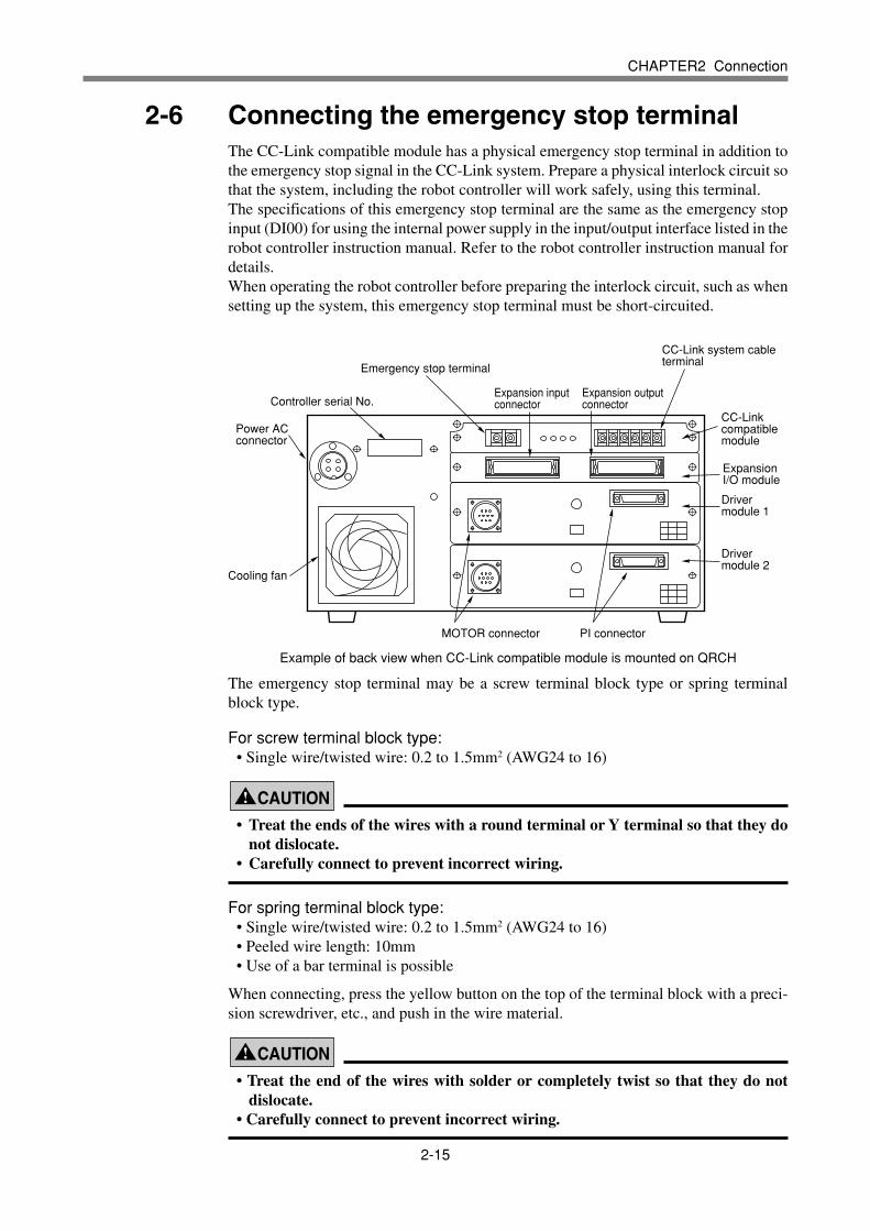
2-6 Connecting the emergency stop terminalThe CC-Link compatible module has a physical emergency stop terminal in addition tothe emergency stop signal in the CC-Link system. Prepare a physical interlock circuit sothat the system, including the robot controller will work safely, using this terminal.The specifications of this emergency stop terminal are the same as the emergency stopinput (DI00) for using the internal power supply in the input/output interface listed in therobot controller instruction manual. Refer to the robot controller instruction manual fordetails.When operating the robot controller before preparing the interlock circuit, such as whensetting up the system, this emergency stop terminal must be short-circuited.
Power AC connector
Cooling fan
Driver module 1
CC-Link compatible module
Driver module 2
Expansion I/O module
Expansion output connector
Expansion input connector
PI connectorMOTOR connector
Controller serial No.
CC-Link system cableterminal
Emergency stop terminal
Example of back view when CC-Link compatible module is mounted on QRCH
The emergency stop terminal may be a screw terminal block type or spring terminalblock type.
For screw terminal block type:• Single wire/twisted wire: 0.2 to 1.5mm2 (AWG24 to 16)
! CAUTION• Treat the ends of the wires with a round terminal or Y terminal so that they do
not dislocate.• Carefully connect to prevent incorrect wiring.
For spring terminal block type:• Single wire/twisted wire: 0.2 to 1.5mm2 (AWG24 to 16)• Peeled wire length: 10mm• Use of a bar terminal is possible
When connecting, press the yellow button on the top of the terminal block with a preci-sion screwdriver, etc., and push in the wire material.
! CAUTION
• Treat the end of the wires with solder or completely twist so that they do notdislocate.
• Carefully connect to prevent incorrect wiring.

2-16
MEMO

CHAPTER1234567890123456789012345678901212345678901234567890123456789012123456789012345678901234567890123456789012345678901234567890121234567890123456789012345678901212345678901234567890123456789012345678901234567890123456789012123456789012345678901234567890121234567890123456789012345678901234567890123456789012345678901212345678901234567890123456789012123456789012345678901234567890123456789012345678901234567890121234567890123456789012345678901212345678901234567890123456789012345678901234567890123456789012123456789012345678901234567890121234567890123456789012345678901234567890123456789012345678901212345678901234567890123456789012123456789012345678901234567890123456789012345678901234567890121234567890123456789012345678901212345678901234567890123456789033
Communication
3-1 State when robot controller power is turned ON .............................3-3
3-2 Initial process for connecting to CC-Link system ............................3-4
3-2-1 Initial data process .......................................................................3-4
3-3 Communication with master station PLC ........................................3-5
3-3-1 Receiving data .............................................................................3-53-3-2 Transmitting data .........................................................................3-6
3-4 Direct connection by emulated serialization on parallel DIO ...........3-7
3-4-1 Setting from teaching box ............................................................3-7
3-5 Referring to communication data ....................................................3-9
3-5-1 Referring to the data from the teaching box .................................3-9

3-2
MEMO

3-3
CHAPTER3 Communication
3-1 State when robot controller power is turned ON
The CC-Link system specification robot controller always starts operation in servo OFFstate when the power turned ON.
q When connection to CC-Link system is correctly established.The following conditions must be satisfied to correctly connect to the CC-Link sys-tem:• The CC-Link system cable must be physically connected• The station No. and communication speed must be correctly set• The master station PLC must be operating correctly
When the robot controller is correctly connected to the CC-Link system, the normalstate will be indicated with the LEDs on the CC-Link compatible module.At this time, the emergency stop signal and interlock signal in the CC-Link systemwill be valid, so these signals must be turned ON with the initial data process.The physical emergency stop signal terminal is always valid.
w When connection to CC-Link system is incorrectly establishedThe following causes can be considered a correct connection with the CC-Link sys-tem cannot be established:• The CC-Link system cable is not physically connected• The station No. or communication speed is set incorrectly• The master station PLC is not operating correctly
When the robot controller is incorrectly connected to the CC-Link system, the errorstate will be indicated with the LEDs on the CC-Link compatible module. Note that ifthe master station PLC is not operating correctly, nothing will appear on the LEDs.The emergency stop signal and interlock signal in the CC-Link system are invalid inthis case, so the robot controller can be operated independently. However, if the cor-rect state has been established even once after the robot controller power was turnedON, the robot controller's emergency stop state cannot be canceled without correctlyconnecting to the CC-Link system.The physical emergency stop signal terminal is always valid.
* Refer to Chapter 4 for details on the LED displays.
3-4
CHAPTER3 Communication
3-2 Initial process for connecting to CC-Link system
The initial data process must be carried out to correctly connect to the CC-Link system.
3-2-1 Initial data process
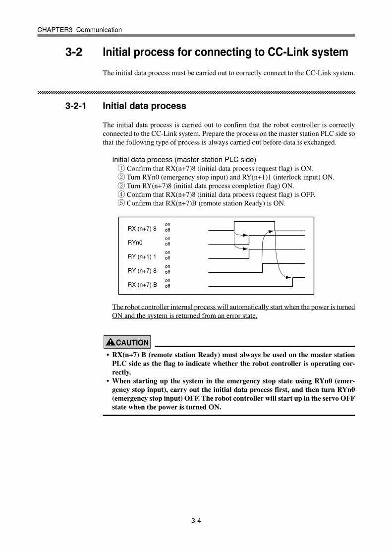
The initial data process is carried out to confirm that the robot controller is correctlyconnected to the CC-Link system. Prepare the process on the master station PLC side sothat the following type of process is always carried out before data is exchanged.
Initial data process (master station PLC side)q Confirm that RX(n+7)8 (initial data process request flag) is ON.w Turn RYn0 (emergency stop input) and RY(n+1)1 (interlock input) ON.e Turn RY(n+7)8 (initial data process completion flag) ON.r Confirm that RX(n+7)8 (initial data process request flag) is OFF.t Confirm that RX(n+7)B (remote station Ready) is ON.
RX (n+7) 8onoff
onoff
onoff
onoff
onoff
RYn0
RY (n+1) 1
RY (n+7) 8
RX (n+7) B
The robot controller internal process will automatically start when the power is turnedON and the system is returned from an error state.
! CAUTION
• RX(n+7) B (remote station Ready) must always be used on the master stationPLC side as the flag to indicate whether the robot controller is operating cor-rectly.
• When starting up the system in the emergency stop state using RYn0 (emer-gency stop input), carry out the initial data process first, and then turn RYn0(emergency stop input) OFF. The robot controller will start up in the servo OFFstate when the power is turned ON.

3-5
CHAPTER3 Communication
3-3 Communication with master station PLC
The method for communicating with the master station PLC by using the robot programwhen the CC-Link system is correctly connected is explained in this section.
3-3-1 Receiving data
Data is received by reading the master station PLC output device data with the robotcontroller's input port.The correspondence of the master station PLC's output device numbers and robot con-troller's input port numbers is shown below.
RYn0 to RYn7
RYn8 to RYnF
RY(n+1)0 to RY(n+1)7
RY(n+1)8 to RY(n+1)F
RY(n+2)0 to RY(n+2)7
RY(n+2)8 to RY(n+2)F
RY(n+3)0 to RY(n+3)7
RY(n+3)8 to RY(n+3)F
RY(n+4)0 to RY(n+4)7
RY(n+4)8 to RY(n+4)F
RY(n+5)0 to RY(n+5)7
RY(n+5)8 to RY(n+5)F
RY(n+6)0 to RY(n+6)7
RY(n+6)8 to RY(n+6)F
SI(00) to SI(07)
SI(10) to SI(17)
SI(20) to SI(27)
SI(30) to SI(37)
SI(40) to SI(47)
SI(50) to SI(57)
SI(60) to SI(67)
SI(70) to SI(77)
SI(100) to SI(107)
SI(110) to SI(117)
SI(120) to SI(127)
SI(130) to SI(137)
SI(140) to SI(147)
SI(150) to SI(157)
n: Address assigned to master module with station No. setting
Master station output device No.
Robot controller input port No.
When reading the bit data from the master station PLC's output device No. with the robotcontroller, write the following commands in the robot program in the same manner asthe DI input port:
WAIT commandSubstitute statement
Example : To wait for RY(n+1)0 to turn ONWAIT SI(20) = 1* The robot program will wait for SI(20) to turn ON.
Example : To read the RY(n+1) 0 to RY(n+1)7 data in variable AA = SI2()
* The SI2() data will be converted into a decimal and substituted into variableA.If SI2() is 7Fh, variable A will be 127.
! CAUTION
• The SI statement in the robot language uses the same syntax as a DI statement.If the SI statement is not described in the programming manual, refer to thesection for the DI statement.

3-6
CHAPTER3 Communication
3-3-2 Transmitting data
Data is transmitted by writing the robot controller output port data into the master stationPLC's input device.The correspondence of the master station PLC's input device numbers and robot control-ler's output port numbers is shown below.
RXn0 to RXn7
RXn8 to RXnF
RX(n+1)0 to RX(n+1)7
RX(n+1)8 to RX(n+1)F
RX(n+2)0 to RX(n+2)7
RX(n+2)8 to RX(n+2)F
RX(n+3)0 to RX(n+3)7
RX(n+3)8 to RX(n+3)F
RX(n+4)0 to RX(n+4)7
RX(n+4)8 to RX(n+4)F
RX(n+5)0 to RX(n+5)7
RX(n+5)8 to RX(n+5)F
RX(n+6)0 to RX(n+6)7
RX(n+6)8 to RX(n+6)F
SO(00) to SO(07)
SO(10) to SO(17)
SO(20) to SO(27)
SO(30) to SO(37)
SO(40) to SO(47)
SO(50) to SO(57)
SO(60) to SO(67)
SO(70) to SO(77)
SO(100) to SO(107)
SO(110) to SO(117)
SO(120) to SO(127)
SO(130) to SO(137)
SO(140) to SO(147)
SO(150) to SO(157)
n: Address assigned to master module with station No. setting
Master station input device No.
Robot controller output port No.
To write the robot controller's bit data into the master station PLC's input device No.,write the following commands in the robot program in the same manner as the DO out-put port:
SET/RESET commandSubstitute statement
Example : To turn RX(n+1)0 ONSET SO(20) or SO(20) =1* SO(20) will turn ON.
Example : To write variable A data into RX(n+1)0 to RX(n+1)7SO2() = A* The variable A data will be converted into a binary and substituted into
SO2().If variable A is 127, 7Fh will be set in SO2().
! CAUTION
• The SO statement in the robot language uses the same syntax as a DO statement.If the SO statement is not described in the programming manual, refer to thesection for the DO statement.

3-7
CHAPTER3 Communication
3-4 Direct connection by emulated serialization on parallel DIO
The master station PLC can exchange ON/OFF information data with the parallel porton the robot controller's expansion I/O module regardless of the robot program. By usingthis function, I/O devices such as a sensor or relay can be used like a device connected toCC-Link.
Master station PLC
Remote device station robot controller
I/O deviceSensor, relay, etc.
Parallel I/O connection
CC-Link connection
When the directly connected and set output port is used with the program, the ON/OFFinformation may not become the intended value. Do not use the directly connected andset output port with the program.
3-4-1 Setting from teaching box
The relation of the parallel port and serial port that can be connected is shown below.
DI4()
DI5()
DI6()
DI7()
SO12()
SO13()
SO14()
SO15()
DO4()
DO5()
DO6()
DO7()
SI12()
SI13()
SI14()
SI15()
Input device such as sensor Output device such as valve DI port SO port DO port SI port → ←
[Operation]1. Press the UTILITY ( LOWER + ESC ) key on the teaching box (hereinafter, MPB) twice
to display the following screen.
UTILITY 6.21AP
Date,Time : 99/05/20,19:02:03
Execut level: LEVEL1
EXECUTE SAFE RST.DO

3-8
CHAPTER3 Communication
2. Next, press the MPB F 6 ( UPPER + F 1 ) [DIO&SIO] key. The following screen
will appear and settings can be made. The highlight indicates the currently selected
port. Select the port using the ←, ← , → and ↓ keys.
3. To set the selected port as a direct connection, press the F 1 (set) key. To cancel the
setting, press the F 2 (reset) key.
“->“/”<-“ will appear in the brackets for the set port.
UTILITY>DIO&SIO 6.21AP
Direct conection (DIO <-> SIO)
DI4():[->]SO12() DO4():[ ]SI12()
DI5():[ ]SO13() DO5():[ ]SI13()
DI6():[->]SO14() DO6():[<-]SI14()
DI7():[ ]SO15() DO7():[ ]SI15()
SET RST.
3-9
CHAPTER3 Communication
3-5 Referring to communication data
The ON/OFF information exchanged with the master station PLC can be referred tousing the teaching box (hereinafter, MPB).Note that the MPB display update interval is longer than the CC-Link data update inter-val, so if the ON/OFF interval is short, accurate information may not be displayed.
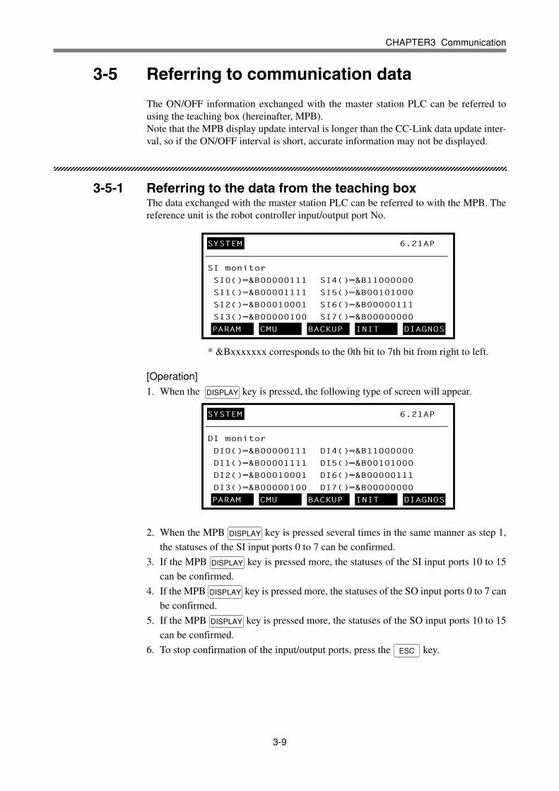
3-5-1 Referring to the data from the teaching boxThe data exchanged with the master station PLC can be referred to with the MPB. Thereference unit is the robot controller input/output port No.
* &Bxxxxxxx corresponds to the 0th bit to 7th bit from right to left.
[Operation]1. When the DISPLAY key is pressed, the following type of screen will appear.
2. When the MPB DISPLAY key is pressed several times in the same manner as step 1,
the statuses of the SI input ports 0 to 7 can be confirmed.
3. If the MPB DISPLAY key is pressed more, the statuses of the SI input ports 10 to 15
can be confirmed.
4. If the MPB DISPLAY key is pressed more, the statuses of the SO input ports 0 to 7 can
be confirmed.
5. If the MPB DISPLAY key is pressed more, the statuses of the SO input ports 10 to 15
can be confirmed.
6. To stop confirmation of the input/output ports, press the ESC key.
SYSTEM 6.21AP
SI monitor
SI0()=&B00000111 SI4()=&B11000000
SI1()=&B00001111 SI5()=&B00101000
SI2()=&B00010001 SI6()=&B00000111
SI3()=&B00000100 SI7()=&B00000000
PARAM CMU BACKUP INIT DIAGNOS
SYSTEM 6.21AP
DI monitor
DI0()=&B00000111 DI4()=&B11000000
DI1()=&B00001111 DI5()=&B00101000
DI2()=&B00010001 DI6()=&B00000111
DI3()=&B00000100 DI7()=&B00000000
PARAM CMU BACKUP INIT DIAGNOS

3-10
MEMO
CHAPTER1234567890123456789012345678901212345678901234567890123456789012123456789012345678901234567890123456789012345678901234567890121234567890123456789012345678901212345678901234567890123456789012345678901234567890123456789012123456789012345678901234567890121234567890123456789012345678901234567890123456789012345678901212345678901234567890123456789012123456789012345678901234567890123456789012345678901234567890121234567890123456789012345678901212345678901234567890123456789012345678901234567890123456789012123456789012345678901234567890121234567890123456789012345678901234567890123456789012345678901212345678901234567890123456789012123456789012345678901234567890123456789012345678901234567890121234567890123456789012345678901212345678901234567890123456789044
Troubleshooting
4-1 Items to confirm before starting up CC-Link system .......................4-3
4-2 Meanings of LEDs on CC-Link compatible module.........................4-4
4-3 Troubleshooting...............................................................................4-5
4-3-1 Robot controller front panel LED confirmation .............................4-54-3-2 Teaching box error display confirmation ...................................... 4-64-3-3 CC-Link compatible module LED confirmation ............................4-74-3-4 Confirmation from master station PLC .........................................4-7

4-2
MEMO
4-3
CHAPTER4 Troubleshooting
4-1 Items to confirm before starting up CC-Link system
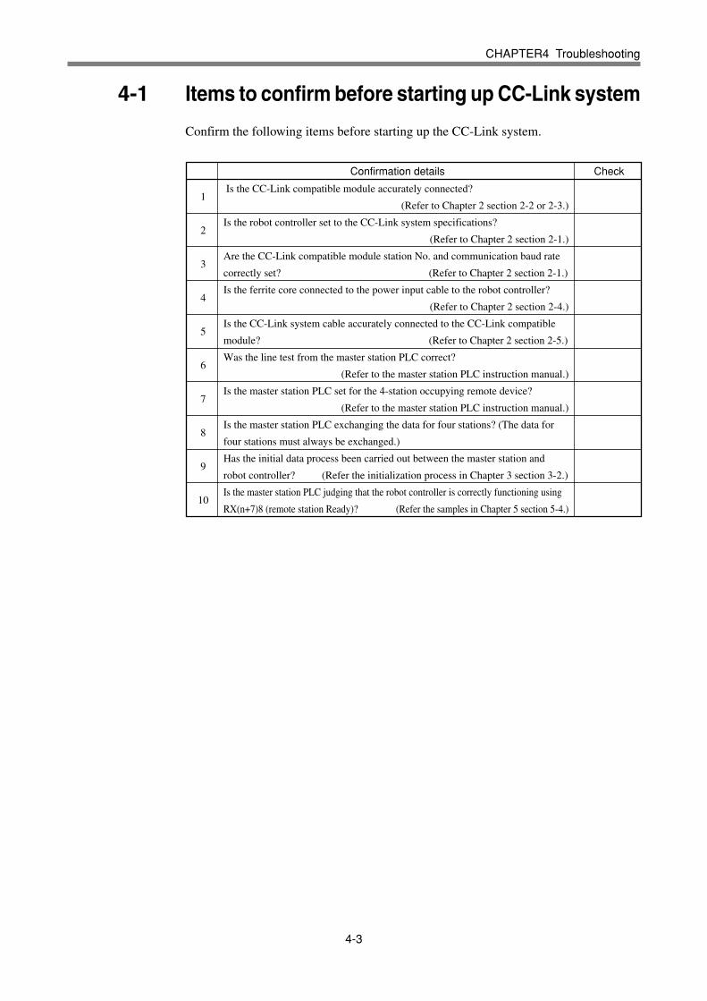
Confirm the following items before starting up the CC-Link system.
1
2
3
4
5
6
7
8
9
10
Confirmation details Check
Is the CC-Link compatible module accurately connected?
(Refer to Chapter 2 section 2-2 or 2-3.)
Is the robot controller set to the CC-Link system specifications?
(Refer to Chapter 2 section 2-1.)
Are the CC-Link compatible module station No. and communication baud rate
correctly set? (Refer to Chapter 2 section 2-1.)
Is the ferrite core connected to the power input cable to the robot controller?
(Refer to Chapter 2 section 2-4.)
Is the CC-Link system cable accurately connected to the CC-Link compatible
module? (Refer to Chapter 2 section 2-5.)
Was the line test from the master station PLC correct?
(Refer to the master station PLC instruction manual.)
Is the master station PLC set for the 4-station occupying remote device?
(Refer to the master station PLC instruction manual.)
Is the master station PLC exchanging the data for four stations? (The data for
four stations must always be exchanged.)
Has the initial data process been carried out between the master station and
robot controller? (Refer the initialization process in Chapter 3 section 3-2.)
Is the master station PLC judging that the robot controller is correctly functioning using
RX(n+7)8 (remote station Ready)? (Refer the samples in Chapter 5 section 5-4.)

4-4
CHAPTER4 Troubleshooting
4-2 Meanings of LEDs on CC-Link compatible module
The LEDs on the CC-Link compatible module express the following statuses.Use these for confirmation when an error occurs.
MeaningRUN ERRL SD RD
Normal communication is taking place, but the CRC error
occurs sometimes because of noise.
The settings have varied from the baud rate and station No.
setting made when connected to the CC-Link system.
A CRC error occurred in the received data, and a response
cannot be made.
Normal communication
There is no data addressed to the local station.
Polling response is being carried out, but a CRC error
occurred in the refresh reception.
A CRC error occurred in the data addressed to the local
station.
There is no data addressed to the local station or the data addressed
to the local station cannot be received because of noise.
Data cannot be received because of a line disconnection.
The power for communication has been cut off.
An illegal baud rate was set. (It can be spefified but differs
from the master station.)
Station No. setting illegal
(An illegal station No. was set.)
Baud rate setting illegal
(An illegal baud rate was set.)
The master station setting does not match the remote device
station setting.
Communication with the master station was not possible
when the power was turned ON.
(This also occurs if the controller is not set for CC-Link.)
( : ON, : OFF, : Flicker)
Others An improbable state
! CAUTION• Even if the LED displays indicate the normal communication state, there may
be cases when communication with the master station PLC is not possible unlessthe initial data process is carried out. Always carry out the initial data process.(Refer to Chapter 3.)

4-5
CHAPTER4 Troubleshooting
4-3 Troubleshooting
If trouble occurs in the connection with the robot controller while starting up the CC-Link system or during operation, check the following items in listed order.
4-3-1 Robot controller front panel LED confirmation4-3-2 Teaching box error display confirmation4-3-3 CC-Link compatible module LED confirmation4-3-4 Confirmation from master station PLC
4-3-1 Robot controller front panel LED confirmation
[Confirmation item 1]<Confirmation details>
• The “POWER” LED is OFF.<Cause>
• Power is not being supplied to the robot controller.<Countermeasures>
• Measure the power input terminal on the power connector with a tester, andconfirm that the rated power is being supplied.
* Refer to the robot controller instruction manual for the rated current values forthe robot controller.
[Confirmation item 2]<Confirmation details>
• The “CPU_OK” LED is OFF.<Cause>
• A major error has occurred in the robot controller.<Countermeasures>
• Confirm the error message displayed on the teaching box.• Take measures by following the troubleshooting section in the robot controller
instruction manual.
* Refer to the robot controller instruction manual for details on the errors.
4-6
CHAPTER4 Troubleshooting
4-3-2 Teaching box error display confirmation
[Confirmation item 1]<Confirmation details>
• “CC-Link Communication Error” is displayed on the teaching box.<Cause>
• An error has occurred in the CC-Link system connection.<Countermeasures>
• Check whether the CC-Link system cable is disconnected or incorrectly con-nected.
• Check the station No. and communication baud rate settings for the CC-Linkcompatible module.
• Confirm that the master station PLC is operating.
[Confirmation item 2]<Confirmation details>
• An error other than “CC-Link Communication Error” is displayed on the teach-ing box. In this case, this problem is not related to the CC-Link system connec-tion.
<Cause>• An error has occurred in the robot controller.
<Countermeasures>• Check the error message displayed on the teaching box.• Check the error history using the teaching box. Check the error history in the
“System > Diagnosis > Error History” mode using the teaching box.• Take measures by following the troubleshooting section in the robot controller
instruction manual.
* Refer to the robot controller instruction manual for details on the errors.

4-7
CHAPTER4 Troubleshooting
4-3-3 CC-Link compatible module LED confirmation
[Confirmation item 1]<Confirmation details>
• The LED display on the CC-Link compatible module is not “RUN. ERR. SD.
RD” = “ ”. ( : ON, : OFF, : Flicker)<Cause>
• An error has occurred in the CC-Link system connection. Refer to table in sec-tion 4-1 for the meanings of the LED displays.
<Countermeasures>• Check whether the CC-Link system cable is disconnected or incorrectly con-
nected, and whether the terminator is connected.• Check whether the CC-Link system cable is laid near the main circuit or power
cable, or whether it is bundled with these.• Check that the ferrite core is connected to the robot controller's power supply
cable.• Check the station No. and communication baud rate settings for the CC-Link
compatible module.• Confirm that the master station PLC is operating.
[Confirmation item 2]<Confirmation details>
• The LED display on the CC-Link compatible module is “RUN, ERR, SD, RD”= “ ”. ( : ON, : OFF, : Flicker)
<Cause>• The initial data process has not been executed when the CC-Link system was
connected. Refer to Chapter 3.• The RX(n+7)B (remote station Ready) signal is not ON.
<Countermeasures>• Carry out the initial data process when connecting to the CC-Link system.
4-3-4 Confirmation from master station PLC
[Confirmation item 1]<Confirmation details>
• Using the master station PLC's line test function, confirm robot controller iscorrectly connected to the CC-Link system.
* Refer to the master station PLC instruction manual for details on the line test.
[Confirmation item 2]<Confirmation details>
• Using the master station PLC's line test function, check whether an error hasoccurred in the robot controller's CC-Link connection.
<Cause>• The ferrite core for noise measures is not connected.• The CC-Link cable is laid near sources of noise such as the power cable.
<Countermeasures>• Connect the ferrite core for noise measures onto the input power cable.• Wire the CC-Link cable away from noise sources such as the power cable.

4-8
MEMO
CHAPTER1234567890123456789012345678901212345678901234567890123456789012123456789012345678901234567890123456789012345678901234567890121234567890123456789012345678901212345678901234567890123456789012345678901234567890123456789012123456789012345678901234567890121234567890123456789012345678901234567890123456789012345678901212345678901234567890123456789012123456789012345678901234567890123456789012345678901234567890121234567890123456789012345678901212345678901234567890123456789012345678901234567890123456789012123456789012345678901234567890121234567890123456789012345678901234567890123456789012345678901212345678901234567890123456789012123456789012345678901234567890123456789012345678901234567890121234567890123456789012345678901212345678901234567890123456789055
Appendix
5-1 Profile ..............................................................................................5-3
5-2 Details of remote input/output signals .............................................5-5
5-3 Dedicated input/output signal timing chart ......................................5-7
5-3-1 Initial data process for CC-Link connection .................................5-75-3-2 Servo ON and emergency stop ....................................................5-85-3-3 Origin return (Valid when incremental motor is connected) ......... 5-95-3-4 Automatic mode changeover, program reset and program execution ........ 5-105-3-5 Stopping with program interlock ................................................. 5-11
5-4 Sample program............................................................................5-12
5-5 CC-Link compatible module specifications ...................................5-19

5-2
MEMO

5-3
CHAPTER5 Appendix
5-1 Profile
YAMAHA robot controller (4-station occupying)
Remote input/output
SO (00): Emergency stop input status output
SO (01): CPU_OK status output
SO (02): Servo ON status output
SO (03): Alarm status output
System area [for future expansion]
SO (10): Automatic mode status output
SO (11): Origin return complete status output
SO (12): Sequence program execution status output
SO (13): Robot program execution status output
SO (14): Program reset status output
System area [for future expansion]
SO(20) to SO(27): General-purpose output
SO(30) to SO(37): General-purpose output
SO(40) to SO(47): General-purpose output
SO(50) to SO(57): General-purpose output
SO(60) to SO(67): General-purpose output
SO(70) to SO(77): General-purpose output
SO(100) to SO(107): General-purpose output
SO(110) to SO(117): General-purpose output
SO(120) to SO(127): General-purpose output
SO(130) to SO(137): General-purpose output
RXn0RXn1RXn2RXn3RXn4RXn5RXn6RXn7RXn8RXn9RXnARXnBRXnCRXnDRXnERXnFRX(n+1)0 toRX(n+1)7RX(n+1)8 toRX(n+1)FRX(n+2)0 toRX(n+2)7RX(n+2)8 toRX(n+2)FRX(n+3)0 toRX(n+3)7RX(n+3)8 toRX(n+3)FRX(n+4)0 toRX(n+4)7RX(n+4)8 toRX(n+4)FRX(n+5)0 toRX(n+5)7RX(n+5)8 toRX(n+5)F
SI (00): Emergency stop input
SI (01): Servo ON input
System area [for future expansion]
SI (10): Sequence control input
SI (11): Interlock input
SI (12): Start input
SI (13): Automatic mode input
SI (14): Origin return input
SI (15): Program reset input
SI (16): Manual mode input
SI (17): Absolute reset input
SI(20) to SI(27): General-purpose input
SI(30) to SI(37): General-purpose input
SI(40) to SI(47): General-purpose input
SI(50) to SI(57): General-purpose input
SI(60) to SI(67): General-purpose input
SI(70) to SI(77): General-purpose input
SI(100) to SI(107): General-purpose input
SI(110) to SI(117): General-purpose input
SI(120) to SI(127): General-purpose input
SI(130) to SI(137): General-purpose input
RYn0RYn1RYn2RYn3RYn4RYn5RYn6RYn7RYn8RYn9RYnARYnBRYnCRYnDRYnERYnFRY(n+1)0 toRY(n+1)7RY(n+1)8 toRY(n+1)FRY(n+2)0 toRY(n+2)7RY(n+2)8 toRY(n+2)FRY(n+3)0 toRY(n+3)7RY(n+3)8 toRY(n+3)FRY(n+4)0 toRY(n+4)7RY(n+4)8 toRY(n+4)FRY(n+5)0 toRY(n+5)7RY(n+5)8 toRY(n+5)F
Remote → Master Master → Remote
Device No. Signal name Device No. Signal name
5-4
CHAPTER5 Appendix
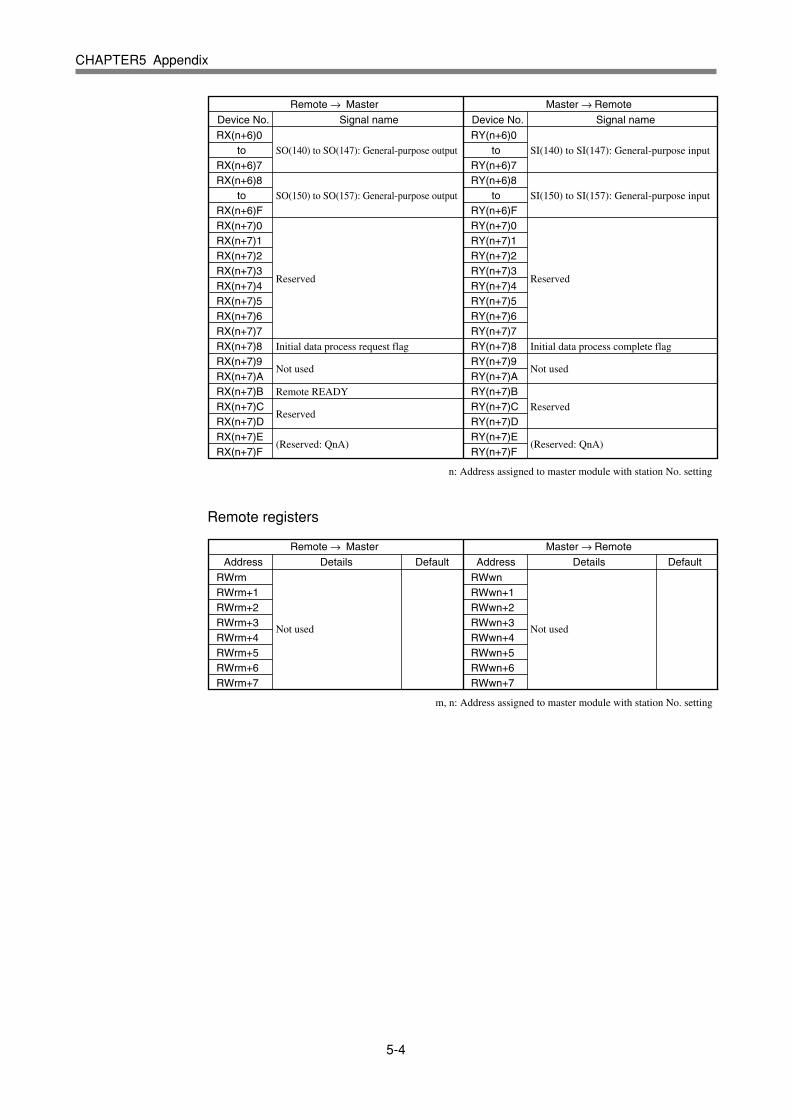
SO(140) to SO(147): General-purpose output
SO(150) to SO(157): General-purpose output
Reserved
Initial data process request flag
Not used
Remote READY
Reserved
(Reserved: QnA)
RX(n+6)0 toRX(n+6)7RX(n+6)8 toRX(n+6)FRX(n+7)0RX(n+7)1RX(n+7)2RX(n+7)3RX(n+7)4RX(n+7)5RX(n+7)6RX(n+7)7RX(n+7)8RX(n+7)9RX(n+7)ARX(n+7)BRX(n+7)CRX(n+7)DRX(n+7)ERX(n+7)F
RY(n+6)0 toRY(n+6)7RY(n+6)8 toRY(n+6)FRY(n+7)0RY(n+7)1RY(n+7)2RY(n+7)3RY(n+7)4RY(n+7)5RY(n+7)6RY(n+7)7RY(n+7)8RY(n+7)9RY(n+7)ARY(n+7)BRY(n+7)CRY(n+7)DRY(n+7)ERY(n+7)F
SI(140) to SI(147): General-purpose input
SI(150) to SI(157): General-purpose input
Reserved
Initial data process complete flag
Not used
Reserved
(Reserved: QnA)
Remote → Master Master → Remote
Device No. Signal name Device No. Signal name
n: Address assigned to master module with station No. setting
Remote registers
Not used
RWrmRWrm+1RWrm+2RWrm+3RWrm+4RWrm+5RWrm+6RWrm+7
RWwnRWwn+1RWwn+2RWwn+3RWwn+4RWwn+5RWwn+6RWwn+7
Not used
Remote → Master Master → Remote
Address Details Default Address Details Default
m, n: Address assigned to master module with station No. setting
5-5
CHAPTER5 Appendix
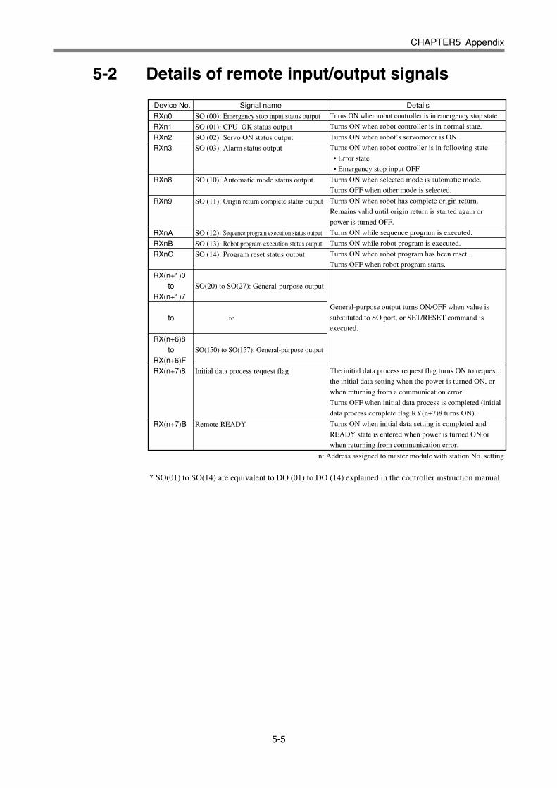
5-2 Details of remote input/output signals
SO (00): Emergency stop input status output
SO (01): CPU_OK status output
SO (02): Servo ON status output
SO (03): Alarm status output
SO (10): Automatic mode status output
SO (11): Origin return complete status output
SO (12): Sequence program execution status output
SO (13): Robot program execution status output
SO (14): Program reset status output
SO(20) to SO(27): General-purpose output
to
SO(150) to SO(157): General-purpose output
Initial data process request flag
Remote READY
RXn0RXn1RXn2RXn3
RXn8
RXn9
RXnARXnBRXnC
RX(n+1)0 toRX(n+1)7
to
RX(n+6)8 toRX(n+6)FRX(n+7)8
RX(n+7)B
Device No. Signal name DetailsTurns ON when robot controller is in emergency stop state.
Turns ON when robot controller is in normal state.
Turns ON when robot’s servomotor is ON.
Turns ON when robot controller is in following state:
• Error state
• Emergency stop input OFF
Turns ON when selected mode is automatic mode.
Turns OFF when other mode is selected.
Turns ON when robot has complete origin return.
Remains valid until origin return is started again or
power is turned OFF.
Turns ON while sequence program is executed.
Turns ON while robot program is executed.
Turns ON when robot program has been reset.
Turns OFF when robot program starts.
General-purpose output turns ON/OFF when value is
substituted to SO port, or SET/RESET command is
executed.
The initial data process request flag turns ON to request
the initial data setting when the power is turned ON, or
when returning from a communication error.
Turns OFF when initial data process is completed (initial
data process complete flag RY(n+7)8 turns ON).
Turns ON when initial data setting is completed and
READY state is entered when power is turned ON or
when returning from communication error.
* SO(01) to SO(14) are equivalent to DO (01) to DO (14) explained in the controller instruction manual.
n: Address assigned to master module with station No. setting
5-6
CHAPTER5 Appendix
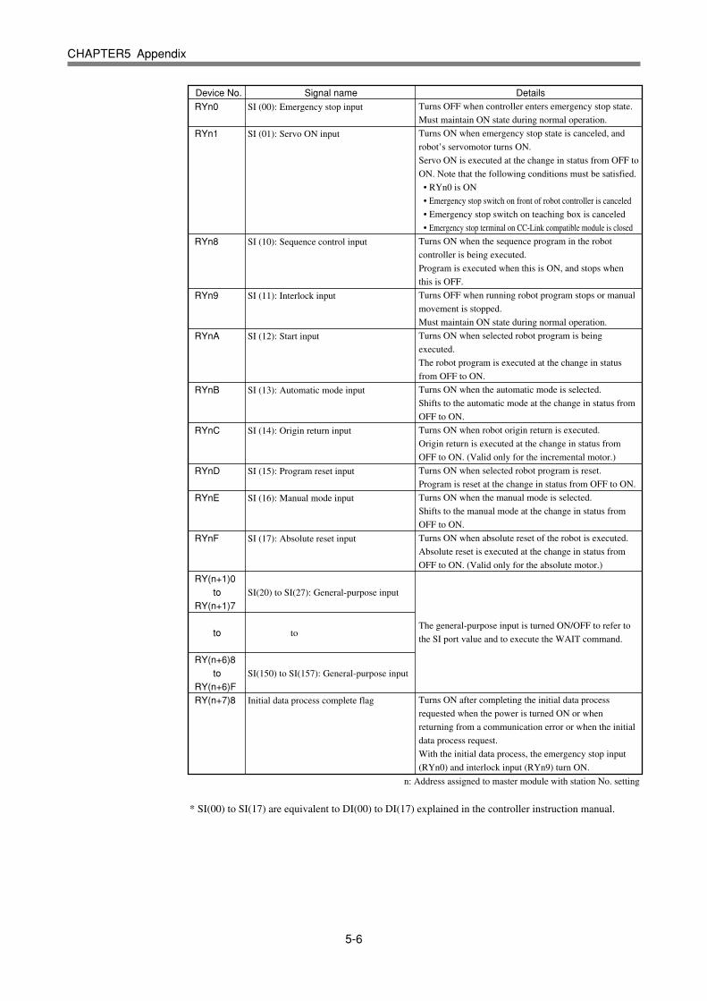
SI (00): Emergency stop input
SI (01): Servo ON input
SI (10): Sequence control input
SI (11): Interlock input
SI (12): Start input
SI (13): Automatic mode input
SI (14): Origin return input
SI (15): Program reset input
SI (16): Manual mode input
SI (17): Absolute reset input
SI(20) to SI(27): General-purpose input
to
SI(150) to SI(157): General-purpose input
Initial data process complete flag
RYn0
RYn1
RYn8
RYn9
RYnA
RYnB
RYnC
RYnD
RYnE
RYnF
RY(n+1)0 toRY(n+1)7
to
RY(n+6)8 toRY(n+6)FRY(n+7)8
Device No. Signal name DetailsTurns OFF when controller enters emergency stop state.
Must maintain ON state during normal operation.
Turns ON when emergency stop state is canceled, and
robot’s servomotor turns ON.
Servo ON is executed at the change in status from OFF to
ON. Note that the following conditions must be satisfied.
• RYn0 is ON
• Emergency stop switch on front of robot controller is canceled
• Emergency stop switch on teaching box is canceled
• Emergency stop terminal on CC-Link compatible module is closed
Turns ON when the sequence program in the robot
controller is being executed.
Program is executed when this is ON, and stops when
this is OFF.
Turns OFF when running robot program stops or manual
movement is stopped.
Must maintain ON state during normal operation.
Turns ON when selected robot program is being
executed.
The robot program is executed at the change in status
from OFF to ON.
Turns ON when the automatic mode is selected.
Shifts to the automatic mode at the change in status from
OFF to ON.
Turns ON when robot origin return is executed.
Origin return is executed at the change in status from
OFF to ON. (Valid only for the incremental motor.)
Turns ON when selected robot program is reset.
Program is reset at the change in status from OFF to ON.
Turns ON when the manual mode is selected.
Shifts to the manual mode at the change in status from
OFF to ON.
Turns ON when absolute reset of the robot is executed.
Absolute reset is executed at the change in status from
OFF to ON. (Valid only for the absolute motor.)
The general-purpose input is turned ON/OFF to refer to
the SI port value and to execute the WAIT command.
Turns ON after completing the initial data process
requested when the power is turned ON or when
returning from a communication error or when the initial
data process request.
With the initial data process, the emergency stop input
(RYn0) and interlock input (RYn9) turn ON.
* SI(00) to SI(17) are equivalent to DI(00) to DI(17) explained in the controller instruction manual.
n: Address assigned to master module with station No. setting

5-7
CHAPTER5 Appendix
5-3 Dedicated input/output signal timing chart
! CAUTION
• The dedicated input ON/OFF process from the master station PLC to the con-troller must be carried out at an interval of 100ms or more. If the interval is tooshort, the dedicated input may not be recognized. (This also applies to the samededicated input and differing dedicated input intervals.)
• If dedicated outputs are provided for the dedicated inputs from the master sta-tion PLC to controller, use them.
5-3-1 Initial data process for CC-Link connection
a) b) c) d) e)
on
on
off
on
off
on
off
on
off
off
RX (n+7) 8Initial data process request flag
RX (n+7) BRemote station Ready
RYn0:SI(00)Emergency stop input
RY(n+1)1:SI(11)Interlock input
RY(n+7)8Initial data process complete flag
Confirmation of connection with master station PLC at power ONa) Initial data process request flag ON is outputb) Emergency stop and interlock input ON is inputc) Initial data process complete flag ON is inputd) Initial data process request flag OFF is outpute) Remote station Ready ON is output
Connection with the CC-Link system is completed with this process.
* This process is always required to correctly connect to the CC-Link system.* To enter the emergency stop state, turn RYn0:SI(00) OFF after the above process is
established.* The servo is OFF when the controller power is turned ON.
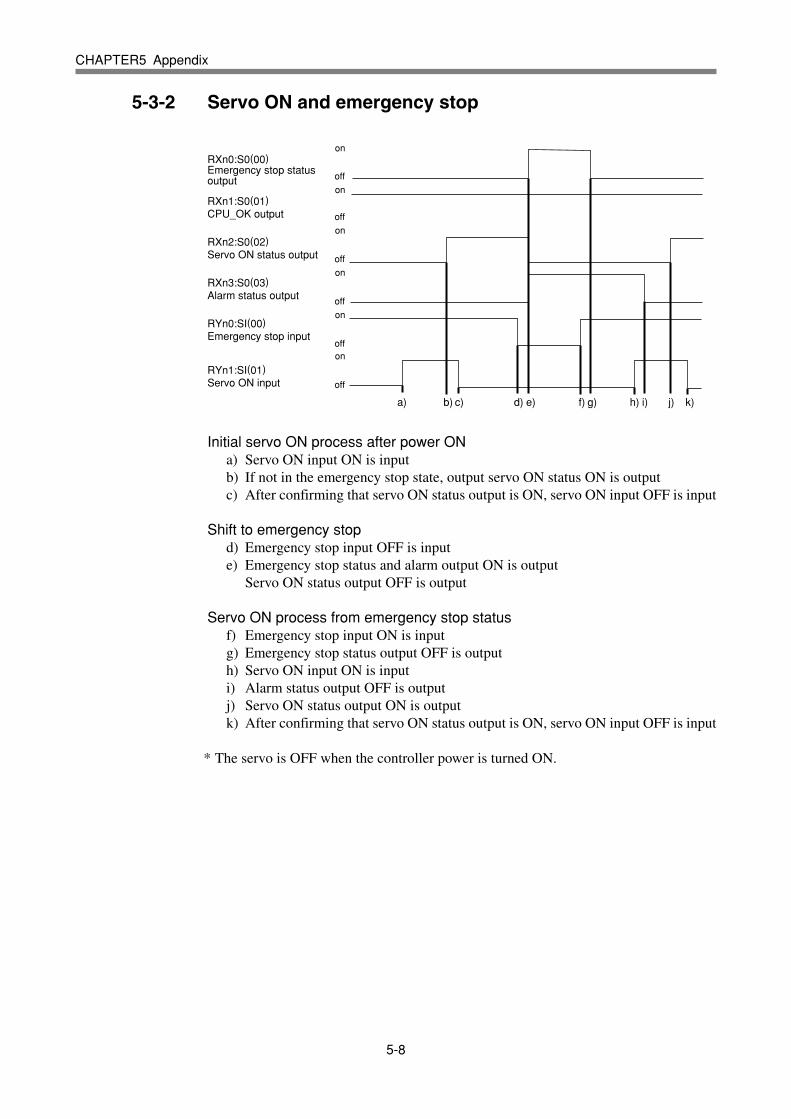
5-8
CHAPTER5 Appendix
5-3-2 Servo ON and emergency stop
a) b) c) d) e) f) g) h) i) j) k)
on
on
off
on
off
on
off
on
on
off
off
off
RXn0:S0(00)Emergency stop status output
RXn1:S0(01)CPU_OK output
RXn2:S0(02)Servo ON status output
RXn3:S0(03)Alarm status output
RYn0:SI(00)Emergency stop input
RYn1:SI(01)Servo ON input
Initial servo ON process after power ONa) Servo ON input ON is inputb) If not in the emergency stop state, output servo ON status ON is outputc) After confirming that servo ON status output is ON, servo ON input OFF is input
Shift to emergency stopd) Emergency stop input OFF is inpute) Emergency stop status and alarm output ON is output
Servo ON status output OFF is output
Servo ON process from emergency stop statusf) Emergency stop input ON is inputg) Emergency stop status output OFF is outputh) Servo ON input ON is inputi) Alarm status output OFF is outputj) Servo ON status output ON is outputk) After confirming that servo ON status output is ON, servo ON input OFF is input
* The servo is OFF when the controller power is turned ON.
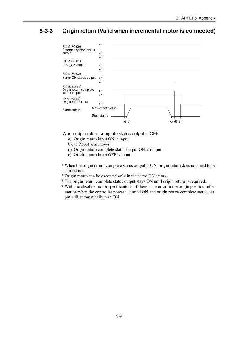
5-9
CHAPTER5 Appendix
5-3-3 Origin return (Valid when incremental motor is connected)
a) b) c) d) e)
on
on
off
on
off
on
off
on
off
off
RXn0:S0(00)Emergency stop status output
RXn1:S0(01)CPU_OK output
RXn2:S0(02)Servo ON status output
RXnB:S0(11)Origin return complete status output
RYnE:SI(14)Origin return input
Alarm status Movement status
Stop status
When origin return complete status output is OFFa) Origin return input ON is inputb), c) Robot arm movesd) Origin return complete status output ON is outpute) Origin return input OFF is input
* When the origin return complete status output is ON, origin return does not need to becarried out.
* Origin return can be executed only in the servo ON status.* The origin return complete status output stays ON until origin return is required.* With the absolute motor specifications, if there is no error in the origin position infor-
mation when the controller power is turned ON, the origin return complete status out-put will automatically turn ON.

5-10
CHAPTER5 Appendix
5-3-4 Automatic mode changeover, program reset and program execution
a) b)
100ms or more 100ms or more
c) d) e) f) g) h) i)
on
on
off
on
off
on
off
on
on
off
off
on
off
on
off
off
RXn8:S0(10)Automatic mode status output
RXn9:S0(11)Origin return complete status output
RXnB:S0(13)Robot program execution status output
RXnC:S0(14)Program reset status output
RYn9:SI(11)Interlock input
RYnA:SI(12)Start input
RYnB:SI(13)Automatic mode input
RYnD:SI(15)Program reset input
Automatic mode changeover processa) Automatic mode input ON is inputb) Automatic mode status output ON is outputc) After confirming that the automatic mode status output is ON, the automatic mode
input OFF is input
Program reset processd) Program reset input ON is inpute) Program reset status output ON is outputf) After confirming that the program reset status output is ON, the program reset
input OFF is input
Program execution processg) Start input ON is inputh) Program reset status output OFF is output
Robot program execution status output ON is outputi) After confirming that the robot program execution status output is ON, the start
input OFF is input
* The program cannot be executed if the emergency stop input and interlock input areOFF.
* If the origin return complete status output is not ON, execution of the program maynot be possible depending on the execution level setting value.

5-11
CHAPTER5 Appendix
5-3-5 Stopping with program interlock
a) b)
100ms or more
c) d) e) f) g) h) i)
on
on
off
on
off
on
off
on
off
off
RXn8:SO(10)Automatic mode status output
RXn9:SO(11)Origin return complete status output
RXnB:SO(13)Robot program execution status output
RYn9:SI(11)Interlock input
RYnA:SI(12)Start input
Program execution processa) Start input ON is inputb) Robot program execution status output ON is outputc) After confirming that the robot program execution status output is ON, the start
input OFF is input
Program stop process using interlock inputd) Interlock input OFF is inpute) Robot program execution status output OFF is output
Program execution after stopping program with interlock inputf) Interlock input ON is inputg) Start input ON is inputh) Robot program execution status output ON is outputi) After confirming that the robot program execution status output is ON, the start
input OFF is input
* The program will also stop when the emergency stop input OFF is input. In this case,the emergency stop status output and alarm output ON will be output, and the servo ONstatus output OFF will be output. The servo ON process is required to start the programagain.

5-12
CHAPTER5 Appendix
5-4 Sample program
An example for the following type of hardware configuration has been prepared for thissection.
P100
MXYt
2nd unit supply position
Pallet
SXYt
1st unit supply position
Master stationA1SHCPU
+A1SJ61BT11
Remote device stationQRCH (1st unit) + SXYt (3 axes) (Station No. 1, 4
stations occupied)
Remote device stationQRCH (2nd unit) + MXYt (3 axes) (Station No. 5, 4
stations occupied)
P101
P102
P103
P104
P201
P202
P203
P204
P105
P106
P107
P108
P205
P206
P207
P208
P200
[Details of sample]• Pick & place work is carried out using the PLC and QRCH + SXYt (3 axes),
QRCH+MXYt (3 axes).• The workpieces supplied to each robot are arranged on one pallet.• The workpiece is supplied at a rate faster than the robot operation.• The two robots will interfere above the pallet, so data is exchanged to prevent inter-
ference.• When handling the workpiece, the robot moves at a low speed.• The robot controller directly exchanges the pallet.
* Refer to the robot programming manual for details on the robot program language.* The PLC circuit is a simple circuit that executes the selected robot program when
emergency stop is canceled.

5-13
CHAPTER5 Appendix
[Robot program data assignment]
* Variables used1st unit : A : Point No. in pallet2nd unit : B : Point No. in pallet
* Points used1st unit : P100 : Point above workpiece supply
P101 : 1st point above pallet: :
P108 : 8th point above palletP121 : Z axis position point for workpiece supplyP122 : Z axis position point on pallet
2nd unit : P200 : Point above workpiece supplyP201 : 1st point above pallet
: :P208 : 8th point above palletP221 : Z axis position point for workpiece supplyP222 : Z axis position point on pallet
* Bit data used1st unit : SI (40) : Point No. reception complete input
SI (41) : Movement complete response standby inputSI (42) : Movement complete standby inputSO (23) to SO (20) : Point No. setting output groupSO (40) : Point No. setting complete outputSO (41) : Movement complete outputSO (42) : Movement complete response outputDI (47) : Pallet change complete inputDO (40) : Chuck hand open close (0: Close, 1: Open)DO (47) : Pallet exchange command output
2nd unit : SI (23) to SI (20) : Point No. setting input groupSI (40) : Point No. transmission complete inputSI (41) : Movement complete standby inputSI (42) : Movement complete response standby inputSO (40) : Point No. setting reception complete outputSO (41) : Movement complete response outputSO (42) : Movement complete outputDO (40) : Chuck hand open/close (0: Close, 1: Open)

5-14
CHAPTER5 Appendix
[PLC data assignment]
X0 (*1) : Unit errorX1 (*1) : Local station data link statusX6 (*1) : Data link start normal completionX7 (*1) : Data link start error completionX0F (*1) : Unit readyX100 : 1st unit’s SO(00): Emergency stop input statusX101 : 1st unit’s SO(01): CPU_OK : :X17F : 1st unit reservationX180 : 2nd unit’s SO(00): Emergency stop input statusX181 : 2nd unit’s SO(01): CPU_OK : :X1FF : 2nd unit reservationY0 (*1) : Refresh instructionY6 (*1) : Data link start requestY100 : 1st unit’s SI(00): Emergency stop inputY101 : 1st unit’s SI(01): Servo ON input : :Y17F : 1st unit reservationY180 : 2nd unit’s SI(00): Emergency stop inputY181 : 2nd unit’s SI(01): Servo ON input : :Y1FF : 2nd unit reservationM0 : Unit preparation complete flagM1 : Parameter setting flagM2 : Data link start flagM4 : 1st station data link statusM8 : 5th station data link statusD0 : No. of connection units storage deviceD1 : 1st unit local station information setting storage deviceD2 : 2nd unit local station information setting storage deviceD10 : Parameter setting status storage device
*1: This number is determined by the master module mounting position and the numberof occupied input/output points mounted before the module.

5-15
CHAPTER5 Appendix
[Robot program]
1st unit’s QRCH ‘INIT ROUTINE
RESET SO2()RESET SO4()RESET DO4()A=101
‘MAIN ROUTINEMOVE P,P100,Z=0GOSUB *PICK
*ST1:MOVE P,P[A],Z=0GOSUB *PLACEMOVE P,P100,Z=0SO(41)=1WAIT SI(41)=1SO(41)=0WAIT SI(41)=0SO(23,22,21,20)=A-100SO(40)=1WAIT SI(40)=1SO(40)=0WAIT SI(40)=0SO(23,22,21,20)=0GOSUB *PICKWAIT SI(42)=1SO(42)=1WAIT SI(42)=0SO(42)=0A=A+1IF A>108 THEN
A=101DO(47)=1WAIT DI(47)=1DO(47)=0
ENDIFGOTO *ST1HALT
‘SUB ROUTINE FOR PICK*PICK:
DO(40)=1DRIVE(3,P121),S=20WAIT ARM(3)DO(40)=0DELAY 500RETURN
‘‘SUB ROUTINE FOR PLACE*PLACE:
DRIVE(3,P122),S=20WAIT ARM(3)DO(40)=1DELAY 500RETURN
2nd unit’s QRCH‘INIT ROUTINE
RESET SO2()RESET SO4()RESET DO4()B=201
‘MAIN ROUTINEMOVE P,P200,Z=0GOSUB *PICK
*ST2:WAIT SI(41)=1SO(41)=1WAIT SI(41)=0SO(41)=0WAIT SI(40)=1B=SI(23,22,21,20)SO(40)=1WAIT SI(40)=0SO(40)=0B=B+200MOVE P,P[B],Z=0GOSUB *PLACEMOVE P,P200,Z=0SO(42)=1WAIT SI(42)=1SO(42)=0WAIT SI(42)=0GOSUB *PICKGOTO *ST2HALT
‘SUB ROUTINE FOR PICK*PICK:
DO(40)=1DRIVE(3,P221),S=20WAIT ARM(3)DO(40)=0DELAY 500RETURN
‘SUB ROUTINE FOR PLACE*PLACE:
DRIVE(3,P222),S=20WAIT ARM(3)DO(40)=1DELAY 500RETURN

5-16
CHAPTER5 Appendix
[PLC program]
0
5
7
42
44
46
48
51
63
91
92
103
107
P10
X0
M0
M1
M9038
M0
M2
X6
X7
X0 X0F X1
M4
M4
M8
M8
M9036
X178
X178
X0F[PLS M0 ]
[SET M1 ]
[RST M1 ]
[SET Y0 ]
[SET M2 ]
[SET Y6 ]
[RST Y6 ]
[RST M2 ]
[RST Y6 ]
[RST M2 ]
[CALL P10 ]
[CALL P20 ]
[SET Y100 ]
[SET Y109 ]
[SET Y178 ]
[RST Y178 ]
(Y20 )
(Y21 )
[FEND ]
[MOV K2 D0 ]
[MOV H1401 D1 ]
[MOV H1405 D2 ]
[TO H0 H1 D0 K1 ]
[T0 H0 H20 D1 K2 ]
[FROM H0 H668 D10 K1 ]
[FROM H0 H680 K4M4 K16 ]
[FROM H0 H0E0 K4X100 K8 ]
No. of connected modules
Station information
Refresh instruction
Data link start normal completion
Data link start error completion
Read each data link status (SW0080)
Station No. 1 normal
Station No. 1 error
Station No. 2 normal
Station No. 2 error
Read station No. 1 remote input
Set emergency stop input ON
Set interlock input ON
Set initial data process compete flag ON
Set initial data process complete flag OFF
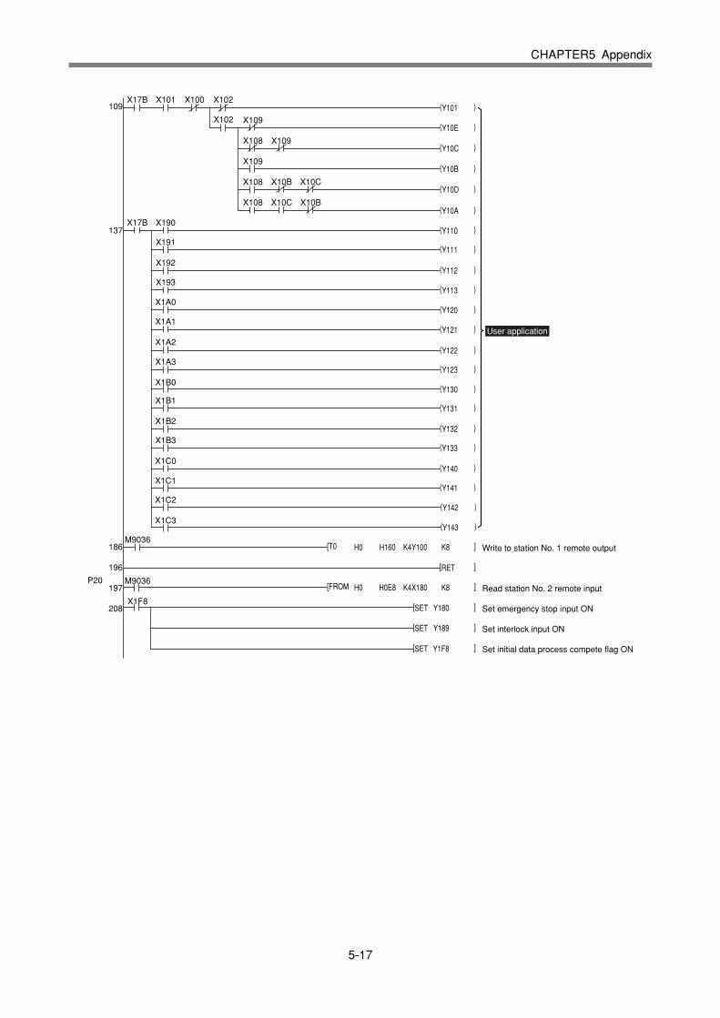
5-17
CHAPTER5 Appendix
109
137
X17B
X102 X109
X108
X109
X108 X10B X10C
X108 X10C X10B
X109
M9036
M9036
X1F8
X101 X100 X102(Y101 )
(Y10E )
(Y10C )
(Y10B )
(Y10D )
(Y10A )
(Y110 )
(Y111 )
(Y112 )
(Y113 )
(Y120 )
(Y121 )
(Y122 )
(Y123 )
(Y130 )
(Y131 )
(Y132 )
(Y133 )
(Y140 )
(Y141 )
(Y142 )
(Y143 )
[RET ]
[SET Y180 ]
[SET Y189 ]
[T0 H0 H160 K4Y100 K8 ]
[FROM H0 H0E8 K4X180 K8 ]
[SET Y1F8 ]
X17B X190
X191
X192
X193
X1A0
X1A1
X1A2
X1A3
X1B0
X1B1
X1B2
X1B3
X1C0
X1C1
X1C2
X1C3
186
196
197
208
P20
User application
Write to station No. 1 remote output
Read station No. 2 remote input
Set emergency stop input ON
Set interlock input ON
Set initial data process compete flag ON
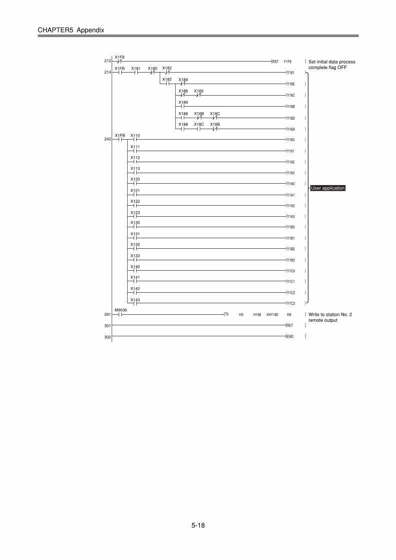
5-18
CHAPTER5 Appendix
212
214
242
X1F8
X1FB X181 X180 X182
X182 X189
X188 X189
X189
X188 X18B X18C
X188 X18C X18B
M9036
[RST Y1F8 ]
(Y181 )
(Y18E )
(Y18C )
(Y18B )
(Y18D )
(Y18A )
(Y190 )
(Y191 )
(Y192 )
(Y193 )
(Y1A0 )
(Y1A1 )
(Y1A2 )
(Y1A3 )
(Y1B0 )
(Y1B1 )
(Y1B2 )
(Y1B3 )
(Y1C0 )
(Y1C1 )
(Y1C2 )
(Y1C3 )
[RET ]
[END ]
[T0 H0 H168 K4Y180 K8 ]
X110X1FB
X111
X112
X113
X120
X121
X122
X123
X130
X131
X132
X133
X140
X141
X142
X143
291
301
302
Set initial data process complete flag OFF
User application
Write to station No. 2 remote output

5-19
CHAPTER5 Appendix
5-5 CC-Link compatible module specifications
The CC-Link compatible module with the label is compatible with CC-Link Ver.1.10. Limits on the station-to-station cable length, etc., can be eased by using the Ver.1.10 compatible CC-Link cable. Refer to the master station PLC instruction manualcompatible with Ver. 1.10.
Target controller QRCH/MRCH/QRCX Series controller
Remote station type Remote device station
Number of occupied stations Fixed to four stations
Station No. setting 1 to 61 (rotary switch)
Communication speed setting 10M / 5M / 2.5M / 625K / 156Kbps (rotary switch)
Number of CC-Link input/output points *1 Dedicated input : 10 points
Dedicated output : 9 points]
General-purpose input : 96 points
General-purpose output : 96 points
Input register : 16 words (currently not used)
Output register : 16 words (currently not used)
Monitor LED RUN, ERRL, SD, RD
Specification item CC-Link compatible module
*1) The controller’s I/O update interval is 10ms.
Note) The specifications and appearance are subject to change without prior notice.

5-20
MEMO