Embed Size (px)
DESCRIPTION
Uploaded from Google Docs
Citation preview
CBT-6PCircuit Breaker Timer
Users Manual
TELDAR INSTRUMENTS CO.
CBT-6P Circuit Breaker TimerUsers Manual
1
1. DESCRIPTION
A circuit breaker is designed to operate reliability when the need arises. Circuit breaker contacttiming is a proven method in checking the synchronism of breaker operation. Operation time testsconducted at the factory, during commissioning and regular intervals are studied and compared toensure proper breaker performance. Breaker manufacturers usually supply acceptable limits in theirmanuals, deviations from such should prompt immediate investigation, repair or replacement of theapparatus.
The CBT-6P is a stand-alone, microprocessor-based instrument for the time testing of distributionand transmission level circuit breakers.
This instrument offers an economical alternative where applications do not require complicatedvelocity and motion measurements, thus involving cumbersome assembly of motion transducers.
The unit has 6 timing channels capable of measuring the operation times of 2 interruptors per phase;each interruptor can consist of a main and a resistor contact in parallel.
Five breaker test operations can be performed: Open, Close, Open-Close, Close-Open, Open-Close-Open. The CBT-6P allows programming of power supply initiate pulse times, while multipleoperation can be initiated by programmable time delay or by sensing breaker’s contact condition.
The CBT-6P has a built-in adjustable DC power supply. This allows the user to run a test withouthaving to use station batteries. External triggering is also possible.
Minimum voltage coil trip test can also be performed.
The panel screen displays the timing trace and the numerical values consisting of open, close,bounce times, delta time and maximum coil current (only for internal DC power supply). Maincontact and resistor dead time is displayed for open-close operation, while main contact and resistorlive time is displayed for close-open operation.
The user can perform point analysis and zoom-in on the trace from the panel controls. The built-inthermal printer allows on-site print-out of both trace and numerical values. Results of test can besaved into the unit’s internal memory and re-called later on.
CBT-6P Circuit Breaker TimerUsers Manual
2
2. SPECIFICATIONS
2.1 Power: 220VAC, 60Hz, 1-phase
2.2 Timing Channels:
6 Inputs 3 Inputs with added insertion resistor measurements
2.3 Timing Window: 1 ~ 1000ms
Accuracy: ± (0.1% of reading ± 2 digits) Resolution: 0.1ms
2.4 DC Power Supply
Output range: 30 ~ 265V, 10A max. Resolution: 1V Accuracy: < 1% Stability: < 1%
2.5 Printer: Thermal printer
2.6 Internal Memory: 40 records
2.7 Dimension & Weight: Unit in box: 43cm L x 38cm W x 30cm H, 14kg.Cables in box: 43cm L x 35cm W x 21cm H, 8kg.
3. FRONT PANEL DESCRIPTION
3.1. Main Power Switch – Turns ON / OFF the machine.
3.2. Mains outlet jack – fuse protected, connects to a 220 Vac, 60 Hz power supply.
3.3. USB port – for software upgrade and diagnostic use only.
3.4. Contrast – contrast adjustment for the LCD screen.
3.5. Large Backlit LCD screen – displays results and timing trace.
3.6. Printer – On-board thermal printer permits on-site printouts of both tabulated resultsand trace.
CBT-6P Circuit Breaker TimerUsers Manual
3
3.7. Ext. Trigger – External voltage trigger inputs from the breaker under test, RED wiresconnects across the CLOSE coil, GREEN wires connects across the OPEN coil.
3.8. DC power supply:
3.8.1. On-board DC supply provides the necessary voltage trigger to activate the OPENand CLOSE coils of the breaker, make sure the breaker is primed before each test.
3.8.2. DC power supply is fully adjustable from 30 to 265 Vdc, it outputs a voltage pulse(duration adjustable) to trigger the coils of the breaker, it is NOT a circuit breakerpower source.
3.8.3. Set the DC adjust knob at its minimum counterclockwise position after every internalDC supply initiated test.
3.9. DC supply output terminals:
3.9.1. BLACK - connected to one side of both the OPEN and CLOSE coils.3.9.2. RED - connected to the CLOSE coil.3.9.3. GREEN - connected to the OPEN coil.
3.10. Timing Input Ports:
6 Channels:o A1 Yellow - Black terminalo B1 Green - Black terminalo C1 Red - Black terminal
o A2 Yellow - Black terminalo B2 Green - Black terminalo C2 Red - Black terminal
3 Channels:With insertion resistor measurementso A1 Yellow - Black terminalo B1 Green - Black terminalo C1 Red - Black terminal
* Connect the channels to a set of circuit breaker contacts under test, take note the initialcondition of the breaker whether it is in OPEN or CLOSE state, make sure that thebreaker is primed properly.
3.11. Printer - Built-in on-board thermal printer, press OPEN button to lift hatch and changethermal paper.
CBT-6P Circuit Breaker TimerUsers Manual
4
4. MAIN MENU
4.1 TEST – Selects the various breaker operation for test: OPEN, CLOSE , CLOSE –OPEN, OPEN – CLOSE, OPEN – CLOSE – OPEN.
4.2. SETTINGS – Selects the trigger mode, initiate and display options.
4.3. VminTrip- Minimum voltage trip test for OPEN and CLOSE operation.
4.4. TRACE – View the contact trace graph of breaker operation.
4.5. PRINT – Print the on-screen results.
4.6. SAVE – Save record to memory.
4.7. LOAD – Retrieve file from memory.
4.8. ChState – Checks the state of the 6 timing channelsO-for OPEN contactC-for CLOSE contact
* At Main Menu, use the left and right arrows to scroll thru the selections, press ENTER toselect.
5. SUBMENU
5.1. Settings menu:
5.1.1. Trigger:
Int or Ext trigger – Internal or External voltage trigger (standard setting)
Channel trigger – Trigger from a channel’s change of state.
* At trigger submenu press ENTER, use left and right keys to scroll thru selections, pressENTER to confirm, select CANCEL to exit.
5.1.2. Initiate: Internal Power supply initiate settings
Open 300ms- Standard voltage trigger pulse duration at 300ms- Adjustable from 1ms to 999ms
CBT-6P Circuit Breaker TimerUsers Manual
5
Close 300ms- Standard voltage trigger pulse duration at 300ms- Adjustable from 1ms to 999ms
Close – Open A1- Standard setting of CLOSE operation first then OPEN after channel A1
changes state.- Select from A1 and I (current)
Open – Close A1- Standard setting of OPEN operation first then CLOSE after channel A1
changes state.- Select from A1 and I (current)
Open 300ms Close-Open A1- Standard setting of OPEN operation first, then CLOSE operation and finally
OPEN after A1 changes state.- Voltage trigger pulse duration adjustable from 1ms to 999ms.- Select from A1 and I (current).
* To change power supply initiate settings, use left and right keys to scroll thru theselections, then press ENTER to highlight parameter, use left and right keys to changevalues, ENTER to confirm and use left and right keys to scroll thru the other selections,go to OK to return to the submenu.
5.1.3. Display: Additional data on tabulated results display.
Imax: Maximum coil current - displays the maximum coil current from internalDC power supply.
Resistor Time - displays the insertion resistor time
* To select these additional data, use left and right keys to select press ENTER to confirm,go to OK to return to the submenu.
5.1.4. Clock: Date and time stamp
* To change values, press ENTER to scroll thru the parameters, use left and right keys tochange values, press ENTER to highlight the whole selection, go to OK to return to thesubmenu.
CBT-6P Circuit Breaker TimerUsers Manual
6
5.2. SAVE menu:
5.2.1. CBT-6P‘s onboard memory can store up to 40 Tabulated and trace results.
5.2.2. After a test, press ENTER to go to SAVE submenu, there are 4 pages for10 tests per page for a total of 40 records.
5.2.3. Users have to decide on which of the memory location to place the saved data.
5.2.4. Use the left and right keys to scroll thru the memory locations, press ENTER toconfirm location, the record number will be highlighted, press ENTER again toinput the 5 character file name, each character will be highlighted, use left and rightkeys to scroll thru the letters and numbers, press ENTER for next character, whenfinished, press ENTER until the whole row is highlighted, use left and right keys toscroll thru the commands.
5.2.5. The SAVE submenu commands are as follows:
UP - use to scroll UP the record page.
DOWN - use to scroll DOWN the record page.
DEL - use to delete a particular record, when highlighted.
SAVE - use to save the record plus its filename to the highlighted record number.
CANCEL - return to main menu
When a particular record number location is highlighted, scroll down to SAVE,press ENTER to save the on-screen tabulated results, trace, time and date stamp.
To delete a file, choose the record number, press ENTER to highlight then scrollto DEL command, press ENTER to delete record.
Select CANCEL to return to Main Menu.
5.3. LOAD menu:
5.3.1. Press ENTER to go to LOAD submenu, there are 4 pages with locations for 10tests for each page for a total of 40 records.
5.3.2. Users have to decide on which of the memory location to retrieve the test record.
CBT-6P Circuit Breaker TimerUsers Manual
7
5.3.3. Use the left and right keys to scroll thru the memory locations, press ENTER toconfirm location, the record number will be highlighted, use left and right keysto scroll thru the commands.
5.3.4. The LOAD submenu commands are as follows: UP - use to scroll UP the record page.
DOWN - use to scroll DOWN the record page.
DEL - use to delete a particular record, when highlighted.
LOAD - use to retrieve the record
CANCEL - return to main menu
When a particular record number location is highlighted, scroll down toLOAD, press ENTER to retrieve the record and post it on-screen.
To delete a file, choose the record number, press ENTER to highlight thenscroll to DEL command, press ENTER to delete record.
Select CANCEL to return to Main Menu.
5.4 PRINT:
5.4.1. Press PRINT to printout the on-screen tabulated results.
5.5. TRACE:
5.5.1. With the tabulated results on-screen, select TRACE to view its timing graphs.
5.5.2. The TRACE submenu commands are as follows:
Zoom In – press ENTER under this selection to zoom in on the graph.
Zoom Out – press ENTER under this selection to zoom out on the graph.
Cursor 1 – press ENTER under this selection to bring up the 1st cursor line, useleft and right keys to move the line, time t indicates the time line in ms, pressENTER to return to submenu.
Cursor 2 – press ENTER under this selection to bring up the 2nd cursor line, useleft and right keys to move the line, time t indicates the time line in ms, delta t
CBT-6P Circuit Breaker TimerUsers Manual
8
indicates the time difference between cursor line 2 and cursor line 1, pressENTER to return to submenu.
PRINT – press ENTER to printout on-screen trace results.
BACK – press ENTER to return to Main Menu.
5.6. VminTrip:
5.6.1. Under VminTrip, the CBT-6P lets users continuously adjust the DC output voltageto the OPEN and CLOSE coils to determine the minimum amount of level foroperation.
5.6.2. Adjust for the initial DC voltage value, select Ok, the CBT-6P will output the setvoltage to either the OPEN or CLOSE coil.
5.6.3. If the breaker did not operate, set the DC voltage to a higher value, then try again.
5.6.4. If it did operate, the value registered on the LED screen is the minimum voltagetrip.
6. CONNECTIONS:
6.1. 6 Timing channels are available for contacts without insertion resistors:
A1 Yellow – Black terminal B1 Green – Black terminal C1 Red – Black terminal
A2 Yellow – Black terminal B2 Green – Black terminal C2 Red – Black terminal
6.2. 3 Timing channels are available for contacts with insertion resistors:
A1 Yellow – Black terminal B1 Green – Black terminal C1 Red – Black terminal
6.3. Connect them across the deenergized breaker contacts.
6.4. Take note of the initial breaker contact state, if it is OPEN or CLOSE, for thosewithout a power supply, hand primed the breaker first.
CBT-6P Circuit Breaker TimerUsers Manual
9
6.5. Connections using CBT-6P DC power supply:
6.5.1. Make sure that the coil control section of the breaker is deenergized.
6.5.2. Set the DC adjust knob to the minimum start position.
6.5.3. Connect one side of the RED, GREEN and BLACK wires to the DC Output Int.Trigger Terminals.
6.5.4. Connect the RED and BLACK wires to the CLOSE coil of the breaker.
6.5.5. Connect the GREEN and BLACK wires to the OPEN coil of the breaker.
6.6. Connections using External Trigger Supply:
6.6.1. The CBT-6P uses the coil trigger voltage from the circuit breaker’s power supply.
6.6.2. Connect the Ext. Trigger plug to the Ext. Trigger terminals.
6.6.3. Connect the two RED wires to the CLOSE coil of the breaker.
6.6.4. Connect the two GREEN wires to the OPEN coil of the breaker.
7. INITIAL SETTINGS:
7.1 At SETTINGS, select TRIGGER, confirm “Int or Ext Trigger” selection.
7.2 At SETTINGS, select INITIATE, confirm these parameters:
Open 300ms Close 300ms Close-Open A1 Open-Close A1 Open 300ms Close-Open A1
7.3. At SETTINGS, select DISPLAY, select additional measurements:
Imax: Maximum Coil Current (when using internal DC power supply) Resistor Time (when measuring contacts with insertion resistors, otherwise do not
activate)
7.4. Check for the correct time and date.
CBT-6P Circuit Breaker TimerUsers Manual
10
8. TIMING OPERATIONS:
8.1. OPEN Operation (Using On-board DC power supply):
8.1.1. Check the breaker contact connections to the CBT-6P, make sure the breaker isprimed and contacts at initial CLOSE position.
8.1.2. Make sure the control section of the breaker coil is deenergized.
8.1.3. Check the connections for DC Output Int. trigger, GREEN and BLACK wires toOPEN coil of breaker.
8.1.4. Turn ON the CBT-6P.
8.1.5. Use the potentiometer to adjust the correct DC coil voltage (always zero start thepower supply before each test).
8.1.6. Select TEST, then select OPEN, press OK to start breaker test.
8.1.7. The CBT-6P will automatically outputs the necessary coil voltage to activatethe breaker and register its operating times and contact traces.
8.1.8. Select PRINT to printout the tabulated results via the on-board thermal printer.
8.1.9. Select TRACE to view the contact graph, select PRINT to printout the trace.
8.1.10. Select SAVE to download record to memory, select the specific memory cell forwhich to store the record, select LOAD to upload the record from memory.
8.2. OPEN Operation (Using Ext- trigger):
8.2.1. Check the breaker contact connections to the CBT-6P, make sure the breaker isprimed and contacts at initial CLOSE position.
8.2.2. The CBT-6P will use the signal from the breaker’s OPEN coil to start count.
8.2.3. Check the connections at Ext. trigger terminals, connect the two GREEN wires tothe OPEN coil of breaker.
8.2.4. Turn ON the CBT-6P.
8.2.5. Select TEST, then select OPEN, press OK to start breaker test.
8.2.6. The CBT-6P will display the message “OPERATE BREAKER NOW !”.
CBT-6P Circuit Breaker TimerUsers Manual
11
8.2.7. Operate the breaker, the signal from the OPEN coil will trigger the CBT-6P’s timingcircuits and register the operating times and contact traces.
8.2.8. Select PRINT to printout the tabulated results via the on-board thermal printer.
8.2.9. Select TRACE to view the contact graph, select PRINT to printout the trace.
8.2.10. Select SAVE to download record to memory, select the specific memory cell forwhich to store the record, select LOAD to upload the record from memory.
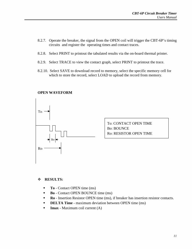
OPEN WAVEFORM
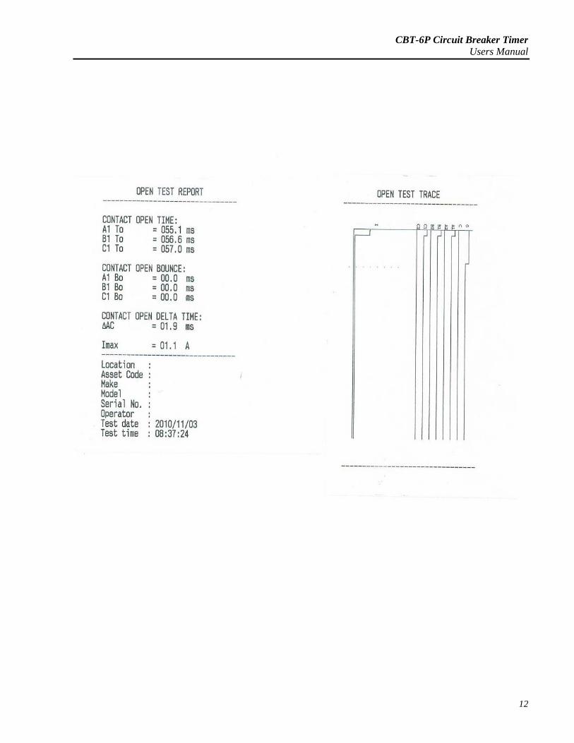
RESULTS:
To - Contact OPEN time (ms)
Bo - Contact OPEN BOUNCE time (ms)
Ro - Insertion Resistor OPEN time (ms), if breaker has insertion resistor contacts.
DELTA Time - maximum deviation between OPEN time (ms)
Imax - Maximum coil current (A)
To
Ro
Bo
To: CONTACT OPEN TIME
Bo: BOUNCE
Ro: RESISTOR OPEN TIME
CBT-6P Circuit Breaker TimerUsers Manual
12
CBT-6P Circuit Breaker TimerUsers Manual
13
8.3. CLOSE Operation (Using On-board DC power supply):
8.3.1. Check the breaker contact connections to the CBT-6P, make sure the breaker isprimed and contacts at initial OPEN position.
8.3.2. Make sure the control section of the breaker coil is deenergized.
8.3.3. Check the connections for DC Output Int. trigger, RED and BLACK wires toCLOSE coil of breaker.
8.3.4. Turn ON the CBT-6P.
8.3.5. Use the potentiometer to adjust the correct DC coil voltage (always zero start thepower supply before each test).
8.3.6. Select TEST, then select CLOSE, press OK to start breaker test.
8.3.7. The CBT-6P will automatically outputs the necessary coil voltage to activate thebreaker and registers its operating time and contact trace.
8.3.8. Select PRINT to printout the tabulated results via the on-board thermal printer.
8.3.9. Select TRACE to view the contact graph, select PRINT to printout the trace.
8.3.10. Select SAVE to download record to memory, select the specific memory cell forwhich to store the record, select LOAD to upload the record from memory.
8.4. CLOSE Operation (Using Ext- trigger)
8.4.1. Check the breaker contact connections to the CBT-6P, make sure the breaker isprimed and contacts at initial OPEN position.
8.4.2. The CBT-6P will use the signal from the breaker’s CLOSE coil to start count.
8.4.3. Check the connections at Ext. trigger terminals , connect the two RED wires to theCLOSE coil of breaker.
8.4.4. Turn ON the CBT-6P.
8.4.5. Select TEST, then select CLOSE, press OK to start breaker test.
8.4.6. The CBT-6P will display the message “OPERATE BREAKER NOW !”.
CBT-6P Circuit Breaker TimerUsers Manual
14
8.4.7. Operate the breaker, the signal from the CLOSE coil will trigger the CBT-6P’stiming circuits and register the breaker’s operating times and contact traces.
8.4.8. Select PRINT to printout the tabulated results via the on-board thermal printer.
8.4.9. Select TRACE to view the contact graph, select PRINT to printout the trace.
8.4.10. Select SAVE to download record to memory, select the specific memory cell forwhich to store the record, select LOAD to upload the record from memory.
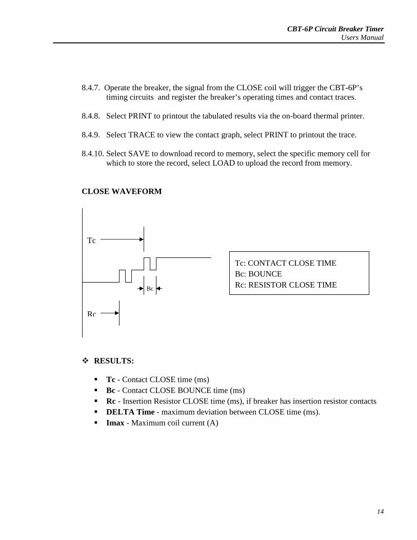
CLOSE WAVEFORM
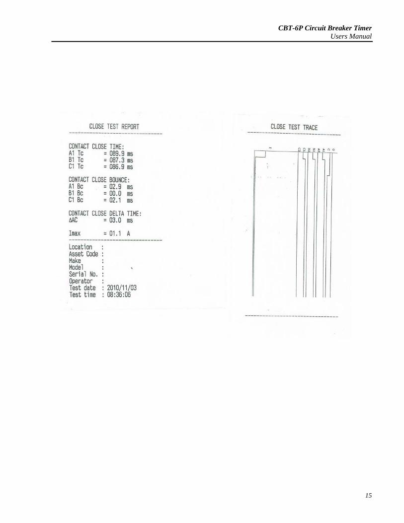
RESULTS:
Tc - Contact CLOSE time (ms)
Bc - Contact CLOSE BOUNCE time (ms)
Rc - Insertion Resistor CLOSE time (ms), if breaker has insertion resistor contacts
DELTA Time - maximum deviation between CLOSE time (ms).
Imax - Maximum coil current (A)
Bc
Tc
Rc
Tc: CONTACT CLOSE TIME
Bc: BOUNCE
Rc: RESISTOR CLOSE TIME
CBT-6P Circuit Breaker TimerUsers Manual
15
CBT-6P Circuit Breaker TimerUsers Manual
16
8.5. CLOSE-OPEN Operation (Using On-board DC Power Supply):
8.5.1. Check the breaker contact connections to the CBT-6P, make sure the breakercontacts are at initial OPEN position, primed and can be configured for thisCLOSE-OPEN test.
8.5.2. Make sure the control section of the breaker coils are deenergized.
8.5.3. Check the connections for DC Output Int. trigger, RED and BLACK wires toCLOSE coil of breaker, GREEN and BLACK wires to the OPEN coil of breaker.
8.5.4. Turn ON the CBT-6P.
8.5.5. Use the potentiometer to adjust the correct DC coil voltage (always zero start thepower supply before each test).
8.5.6. Select TEST, then select CLOSE-OPEN, press OK to start breaker test.
8.5.7. The CBT-6P will automatically outputs the necessary coil voltage to activate thebreaker test sequence and register its operating times and contact traces.
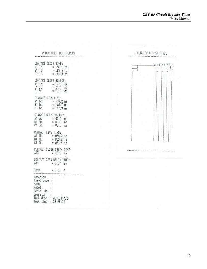
8.5.8. Select PRINT to printout the tabulated results via the on-board thermal printer.
8.5.9. Select TRACE to view the contact graph, select PRINT to printout the trace.
8.5.10. Select SAVE to download record to memory, select the specific memory cellfor which to store the record, select LOAD to upload the record from memory.
CBT-6P Circuit Breaker TimerUsers Manual
17
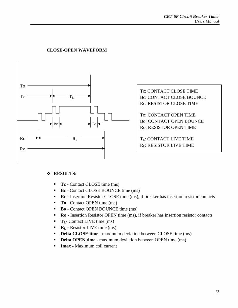
CLOSE-OPEN WAVEFORM
RESULTS:
Tc - Contact CLOSE time (ms)
Bc - Contact CLOSE BOUNCE time (ms)
Rc - Insertion Resistor CLOSE time (ms), if breaker has insertion resistor contacts
To - Contact OPEN time (ms)
Bo - Contact OPEN BOUNCE time (ms)
Ro - Insertion Resistor OPEN time (ms), if breaker has insertion resistor contacts
TL- Contact LIVE time (ms)
RL - Resistor LIVE time (ms)
Delta CLOSE time - maximum deviation between CLOSE time (ms)
Delta OPEN time - maximum deviation between OPEN time (ms).
Imax - Maximum coil current
BoBc
TLTc
To
RLRc
Ro
Tc: CONTACT CLOSE TIME
Bc: CONTACT CLOSE BOUNCE
Rc: RESISTOR CLOSE TIME
To: CONTACT OPEN TIME
Bo: CONTACT OPEN BOUNCE
Ro: RESISTOR OPEN TIME
TL: CONTACT LIVE TIME
RL: RESISTOR LIVE TIME
CBT-6P Circuit Breaker TimerUsers Manual
18
CBT-6P Circuit Breaker TimerUsers Manual
19
8.6. OPEN-CLOSE Operation (Using On-board DC Power Supply):
8.6.1. Check the breaker contact connections to the CBT-6P, make sure the breakercontacts are at initial CLOSE position, primed and can be configured for thisOPEN-CLOSE test.
8.6.2. Make sure the control section of the breaker coils are deenergized.
8.6.3. Check the connections for DC Output Int. trigger, RED and BLACK wires toCLOSE coil of breaker, GREEN and BLACK wires to the OPEN coil of breaker.
8.6.4. Turn ON the CBT-6P.
8.6.5. Use the potentiometer to adjust the correct DC coil voltage (always zero start thepower supply before each test).
8.6.6. Select TEST, then select OPEN-CLOSE , press OK to start breaker test.
8.6.7. The CBT-6P will automatically outputs the necessary coil voltage to activate thebreaker test sequence and register its operating times and contact traces.
8.6.8. Select PRINT to printout the tabulated results via the on-board thermal printer.
8.6.9. Select TRACE to view the contact graph, select PRINT to printout the trace.
8.6.10. Select SAVE to download record to memory, select the specific memory cell forwhich to store the record, select LOAD to upload the record from memory.
CBT-6P Circuit Breaker TimerUsers Manual
20
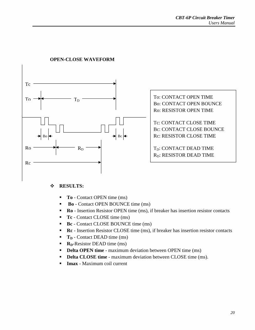
OPEN-CLOSE WAVEFORM
RESULTS:
To - Contact OPEN time (ms)
Bo - Contact OPEN BOUNCE time (ms)
Ro - Insertion Resistor OPEN time (ms), if breaker has insertion resistor contacts
Tc - Contact CLOSE time (ms)
Bc - Contact CLOSE BOUNCE time (ms)
Rc - Insertion Resistor CLOSE time (ms), if breaker has insertion resistor contacts
TD - Contact DEAD time (ms)
RD-Resistor DEAD time (ms)
Delta OPEN time - maximum deviation between OPEN time (ms)
Delta CLOSE time - maximum deviation between CLOSE time (ms).
Imax - Maximum coil current
RD
TD
Tc
To
Ro
Rc
BcBo
To: CONTACT OPEN TIME
Bo: CONTACT OPEN BOUNCE
Ro: RESISTOR OPEN TIME
Tc: CONTACT CLOSE TIME
Bc: CONTACT CLOSE BOUNCE
Rc: RESISTOR CLOSE TIME
TD: CONTACT DEAD TIME
RD: RESISTOR DEAD TIME
CBT-6P Circuit Breaker TimerUsers Manual
21
CBT-6P Circuit Breaker TimerUsers Manual
22
8.7. OPEN-CLOSE-OPEN Operation (Using On-board DC Power Supply):
8.7.1. Check the breaker contact connections to the CBT-6P, make sure the breakercontacts are at initial CLOSE position, primed and can be configured for this OPEN-CLOSE-OPEN test.
8.7.2. Make sure the control section of the breaker coils are deenergized.
8.7.3. Check the connections for DC Output Int. trigger, RED and BLACK wires toCLOSE coil of breaker, GREEN and BLACK wires to the OPEN coil of breaker.
8.7.4. Turn ON the CBT-6P.
8.7.5. Use the potentiometer to adjust the correct DC coil voltage (always zero start thepower supply before each test).
8.7.6. Select TEST, then select OPEN-CLOSE-OPEN , press OK to start breaker test.
8.7.7. The CBT-6P will automatically outputs the necessary coil voltage to activate thebreaker test sequence and register its operating times and contact traces.
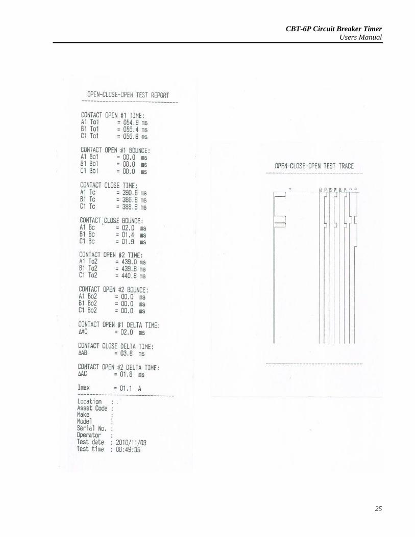
8.7.8. Select PRINT to printout the tabulated results via the on-board thermal printer.
8.7.9. Select TRACE to view the contact graph, select PRINT to printout the trace.
8.7.10. Select SAVE to download record to memory, select the specific memory cell forwhich to store the record, select LOAD to upload the record from memory.
CBT-6P Circuit Breaker TimerUsers Manual
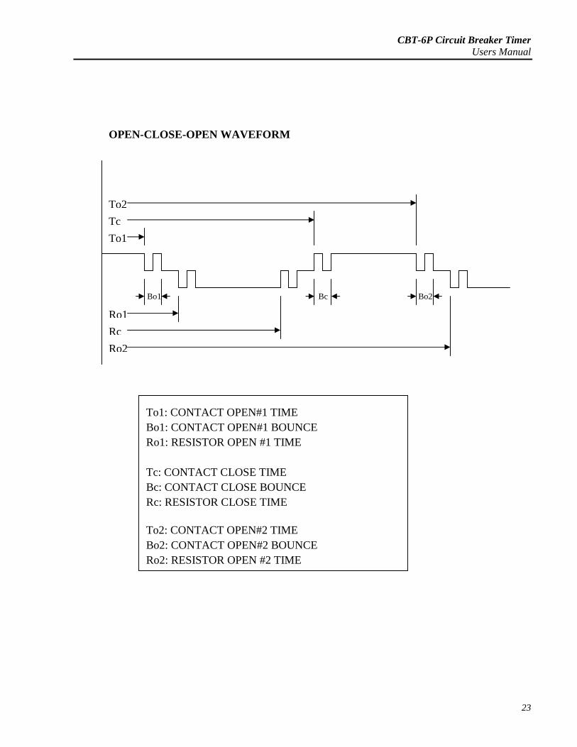
OPEN-CLOSE-OPEN WAVEFORM
Ro2
Ro1
Rc
To2
To1
Tc
BcBo1 Bo2
To1: CONTACT OPEN#1 TIME
Bo1: CONTACT OPEN#1 BOUNCE
Ro1: RESISTOR OPEN #1 TIME
Tc: CONTACT CLOSE TIME
Bc: CONTACT CLOSE BOUNCE
Rc: RESISTOR CLOSE TIME
To2: CONTACT OPEN#2 TIME
Bo2: CONTACT OPEN#2 BOUNCE
23
Ro2: RESISTOR OPEN #2 TIME
CBT-6P Circuit Breaker TimerUsers Manual
24
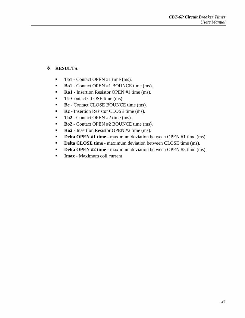
RESULTS:
To1 - Contact OPEN #1 time (ms).
Bo1 - Contact OPEN #1 BOUNCE time (ms).
Ro1 - Insertion Resistor OPEN #1 time (ms).
Tc-Contact CLOSE time (ms).
Bc - Contact CLOSE BOUNCE time (ms).
Rc - Insertion Resistor CLOSE time (ms).
To2 - Contact OPEN #2 time (ms).
Bo2 - Contact OPEN #2 BOUNCE time (ms).
Ro2 - Insertion Resistor OPEN #2 time (ms).
Delta OPEN #1 time - maximum deviation between OPEN #1 time (ms).
Delta CLOSE time - maximum deviation between CLOSE time (ms).
Delta OPEN #2 time - maximum deviation between OPEN #2 time (ms).
Imax - Maximum coil current
CBT-6P Circuit Breaker TimerUsers Manual
25
CBT-6P Circuit Breaker TimerUsers Manual
26
PARTS LIST
Transport case for CBT-6P
Transport case for cables
DC output supply cable
External trigger sense cable
2 sets Red, Yellow, Green sense cables
5 pcs. Black cables
1 pc. Interconnect cable
6 pcs. Shorting cable
Mains cable
Manuals


![Ultrameter Operation Manual Model 6P - [Official] Myron L ... · Ultrameter™ Operation Manual Model 6P 10 - 02 (WEB) EG MYRON L COMPANY. 7-1 1-00 Reference Junction under Glass](https://img.dokumen.tips/doc/110x75/5afd383c7f8b9a944d8d206b/ultrameter-operation-manual-model-6p-official-myron-l-operation-manual.jpg)


![HP LaserJet 5P - 6P Service Manual [Proper]](https://img.dokumen.tips/doc/110x75/577cc3a81a28aba71196bc1b/hp-laserjet-5p-6p-service-manual-proper.jpg)