Embed Size (px)
Citation preview
Technical Notes
INDEX
Physical properties of clay brick History Manufacture of brick Sizes, colours, shapes and orientation Moisture penetration through brickwork Use of waterproofing sealers Fire rating of clay brick veneer walls Thermal resistance of masonry Sound transmission of masonry Movement joints Sustainability Cleaning of brick Efflorescence CSA A82 requirements Freeze thaw tests Absorption tests Compressive strength test Initial rate of absorption (IRA) Finish Efflorescence test Dimensions Quantities of brick and mortar
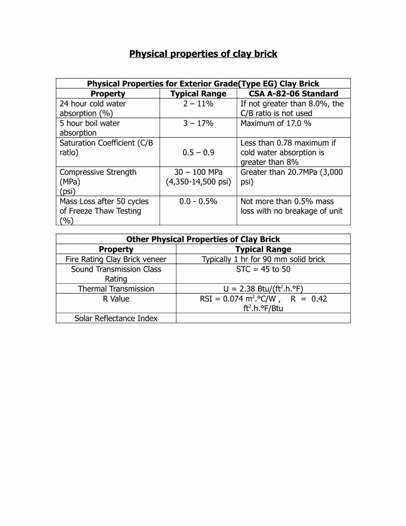
Physical properties of clay brick
Physical Properties for Exterior Grade(Type EG) Clay BrickProperty Typical Range CSA A-82-06 Standard
24 hour cold water absorption (%)
2 – 11% If not greater than 8.0%, the C/B ratio is not used
5 hour boil water absorption
3 – 17% Maximum of 17.0 %
Saturation Coefficient (C/B ratio) 0.5 – 0.9
Less than 0.78 maximum if cold water absorption is greater than 8%
Compressive Strength (MPa)(psi)
30 – 100 MPa(4,350-14,500 psi)
Greater than 20.7MPa (3,000 psi)
Mass Loss after 50 cycles of Freeze Thaw Testing (%)
0.0 - 0.5% Not more than 0.5% mass loss with no breakage of unit
Other Physical Properties of Clay BrickProperty Typical Range
Fire Rating Clay Brick veneer Typically 1 hr for 90 mm solid brickSound Transmission Class
RatingSTC = 45 to 50
Thermal Transmission U = 2.38 Btu/(ft2.h.°F)R Value RSI = 0.074 m2.°C/W , R = 0.42
ft2.h.°F/BtuSolar Reflectance Index
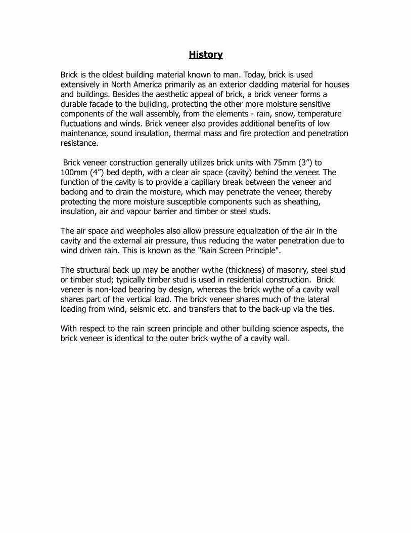
History
Brick is the oldest building material known to man. Today, brick is used extensively in North America primarily as an exterior cladding material for houses and buildings. Besides the aesthetic appeal of brick, a brick veneer forms a durable facade to the building, protecting the other more moisture sensitive components of the wall assembly, from the elements - rain, snow, temperature fluctuations and winds. Brick veneer also provides additional benefits of low maintenance, sound insulation, thermal mass and fire protection and penetration resistance.
Brick veneer construction generally utilizes brick units with 75mm (3”) to 100mm (4”) bed depth, with a clear air space (cavity) behind the veneer. The function of the cavity is to provide a capillary break between the veneer and backing and to drain the moisture, which may penetrate the veneer, thereby protecting the more moisture susceptible components such as sheathing, insulation, air and vapour barrier and timber or steel studs. The air space and weepholes also allow pressure equalization of the air in the cavity and the external air pressure, thus reducing the water penetration due to wind driven rain. This is known as the "Rain Screen Principle".
The structural back up may be another wythe (thickness) of masonry, steel stud or timber stud; typically timber stud is used in residential construction. Brick veneer is non-load bearing by design, whereas the brick wythe of a cavity wall shares part of the vertical load. The brick veneer shares much of the lateral loading from wind, seismic etc. and transfers that to the back-up via the ties.
With respect to the rain screen principle and other building science aspects, the brick veneer is identical to the outer brick wythe of a cavity wall.
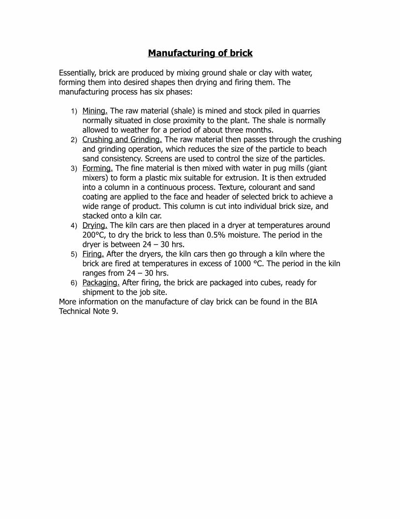
Manufacturing of brick
Essentially, brick are produced by mixing ground shale or clay with water, forming them into desired shapes then drying and firing them. The manufacturing process has six phases:
1) Mining . The raw material (shale) is mined and stock piled in quarries normally situated in close proximity to the plant. The shale is normally allowed to weather for a period of about three months.
2) Crushing and Grinding . The raw material then passes through the crushing and grinding operation, which reduces the size of the particle to beach sand consistency. Screens are used to control the size of the particles.
3) Forming . The fine material is then mixed with water in pug mills (giant mixers) to form a plastic mix suitable for extrusion. It is then extruded into a column in a continuous process. Texture, colourant and sand coating are applied to the face and header of selected brick to achieve a wide range of product. This column is cut into individual brick size, and stacked onto a kiln car.
4) Drying . The kiln cars are then placed in a dryer at temperatures around 200°C, to dry the brick to less than 0.5% moisture. The period in the dryer is between 24 – 30 hrs.
5) Firing . After the dryers, the kiln cars then go through a kiln where the brick are fired at temperatures in excess of 1000 °C. The period in the kiln ranges from 24 – 30 hrs.
6) Packaging . After firing, the brick are packaged into cubes, ready for shipment to the job site.
More information on the manufacture of clay brick can be found in the BIA Technical Note 9.
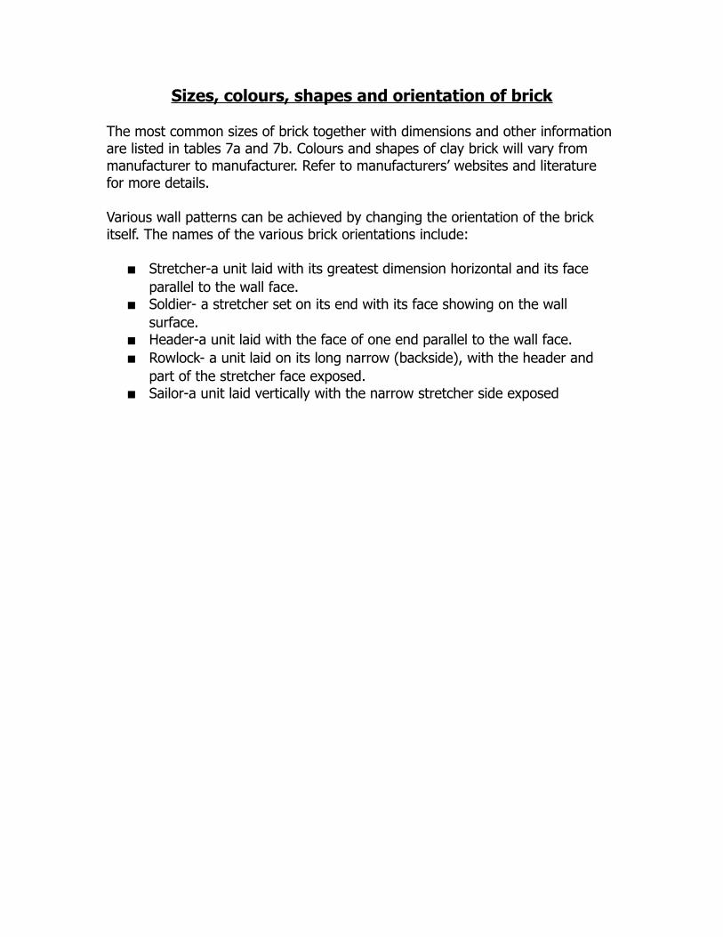
Sizes, colours, shapes and orientation of brick
The most common sizes of brick together with dimensions and other information are listed in tables 7a and 7b. Colours and shapes of clay brick will vary from manufacturer to manufacturer. Refer to manufacturers’ websites and literature for more details.
Various wall patterns can be achieved by changing the orientation of the brick itself. The names of the various brick orientations include:
Stretcher-a unit laid with its greatest dimension horizontal and its face parallel to the wall face.
Soldier- a stretcher set on its end with its face showing on the wall surface.
Header-a unit laid with the face of one end parallel to the wall face. Rowlock- a unit laid on its long narrow (backside), with the header and
part of the stretcher face exposed. Sailor-a unit laid vertically with the narrow stretcher side exposed
Moisture penetration through brickwork
Brick veneer cladding and brick cavity walls provide superior protection for a building against water penetration. However, occasionally there are situations where there is water leakage into the interior. In many such situations, the brick is erroneously blamed for the leakage. The fact that water permeates beyond the brick veneer does not mean the brick, the mortar or the workmanship is deficient.
The brick veneer wall system is a “drainage” or “Rain Screen” wall system.A typical brick veneer / cavity wall comprises of a back up wall (concrete block, timber or metal studs), the brick veneer, and a drainage cavity (air space) which separates the brick veneer from the back up wall. The design and construction of this wall system allows that water may occasionally penetrate the brick veneer, but on reaching the cavity, will drain downwards and be directed to the exterior of the building. The cavity provides many very important functions in ensuring that the interior of the building remains dry, namely:
A capillary break between the outer wythe (brick veneer) and the back-up wall
A drainage path to allow any water that does penetrate the brick veneer to drain to the base of the cavity and to the exterior
It allows for the drying out of the elements adjacent to the cavity Venting provides partial pressure equalization between the cavity and the
exterior. This reduces the amount of moisture, which could be driven through the
brick veneer due to driving rain.The importance and effectiveness of this cavity is now recognized throughout North America. Some building authorities now stipulate a drainage cavity in all wall systems. For the drainage wall system to operate effectively, the following details need to be in place:
a) Brick Veneer. Although the leakage of water through the brick veneer does not constitute a deficiency, it is prudent to minimize the amount of moisture which does get through. Although a well burned clay brick is porous, very little water will permeate through the brick itself. Experience and studies shows that any moisture, which does penetrate the brick veneer, does so mainly through voids in the mortar joints. The use of well proportioned mortar and the tooling of the joints (concave) will significantly reduce moisture penetration.
b) Cavity. The cavity should be clear and continuous. The width of a cavity behind a brick veneer is typically 25 – 50 mm (1” – 2”). Although some mortar droppings do fall into the cavity, the cavity should be reasonably clear. The use of pebbles or proprietary net products placed at the base of
the cavity help keep the important drainage area free from mortar droppings.
c) Wall Ties. Wall ties should be so designed and installed so that they do not allow water to traverse the cavity.
d) Flashing: Through-wall flashing should be installed at the base of the cavity, above any openings in the wall, and above the roof line at any point where the wall traverses the roofline. End dams should be constructed at the termination of flashing, eg against doors, columns, on lintels and shelf angles etc. Flashing should be adequately lapped and sealed. Corner details of flashing should be detailed appropriately. Flashing should extend six inches up the back-up wall, be well secured and lapped behind the building paper or house wrap, and extend to the exterior beyond the brickwork. Refer to technical note on Flashing.
e) Weepholes: Weepholes are normally constructed by leaving an open header on the first course at approximately 600mm (24 inches) spacing. The weepholes should be unobstructed, to allow for drainage.
f) The flashing and weepholes at the base of the wall should be at least 150 mm (6 inches) above finished grade to allow for free draining.
Use of water proofing sealers
Many people think that putting water repellent on a clay brick masonry wall will help keep out the moisture and prolong the life of it. Sometimes water repellents are applied to address problems of excessive moisture or leakage in the wall. The fact is that a wall designed and constructed using best practice does not need to be treated with water repellent. Walls with excessive moisture issues are best addressed by fixing the root cause of the problem.
Putting water repellents on the wall could lead to premature freeze thaw deterioration due to entrapment of the water inside the clay brick masonry, even though many of the repellents on the market today are said to be “breathable”. Although water repellents may reduce the surface absorption of moisture due to rain, the cause of deterioration is usually due to moisture sources that build up in the wall. These sources include:
Interior moisture, like warm interior air, condensing on a cold wall Exterior moisture that enters the wall through poor mortar joints,
deteriorated sealants or improper application of moisture control features
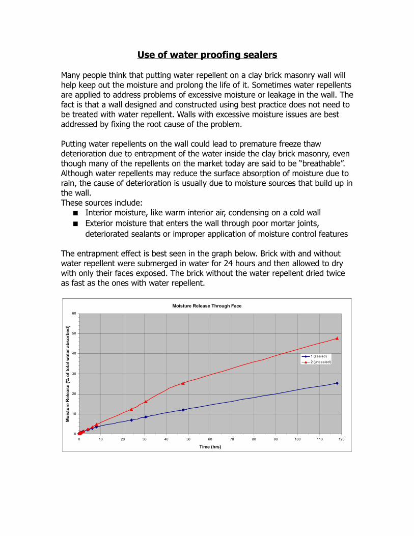
The entrapment effect is best seen in the graph below. Brick with and without water repellent were submerged in water for 24 hours and then allowed to dry with only their faces exposed. The brick without the water repellent dried twice as fast as the ones with water repellent.
Moisture Release Through Face
0
10
20
30
40
50
60
0 10 20 30 40 50 60 70 80 90 100 110 120
Time (hrs)
Mo
istu
re R
ele
as
e (
% o
f to
tal w
ate
r a
bs
orb
ed
)
1 (sealed)
2 (unsealed)
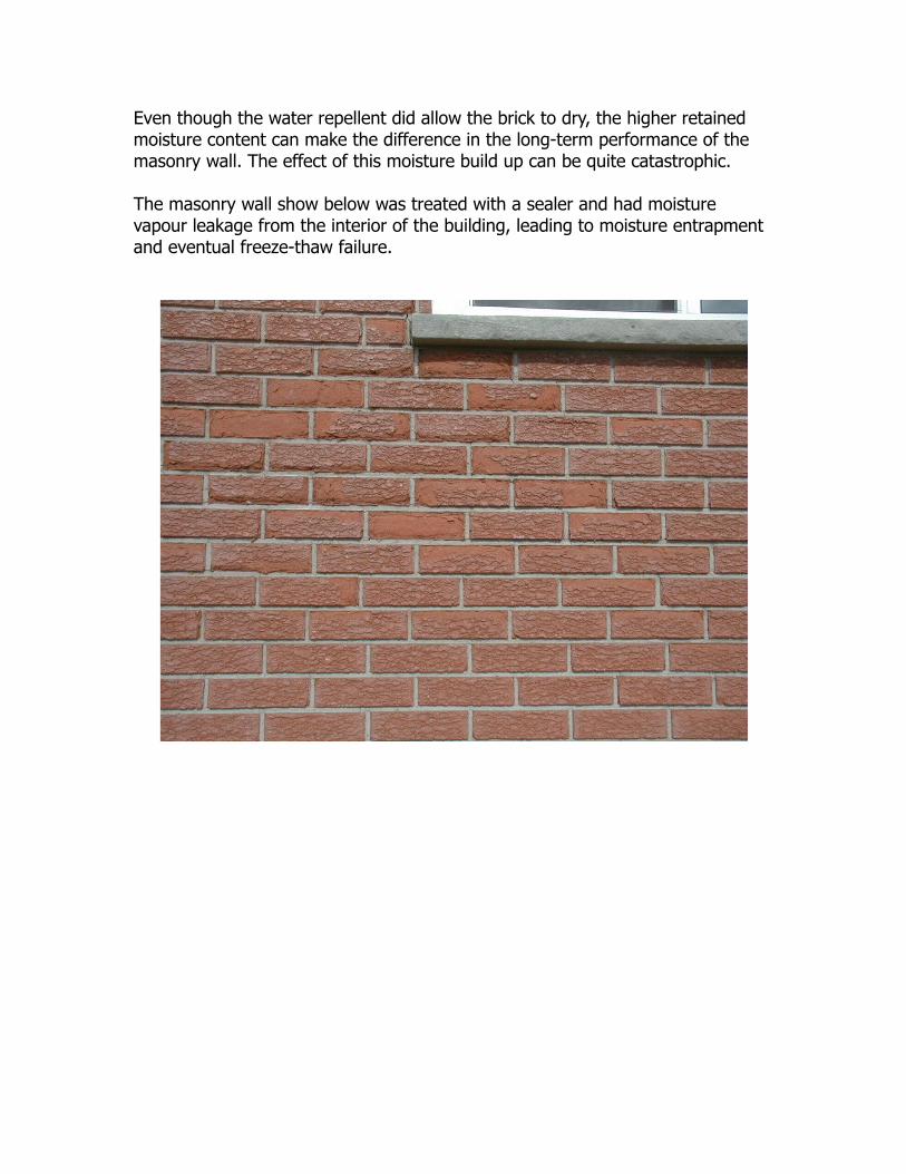
Even though the water repellent did allow the brick to dry, the higher retained moisture content can make the difference in the long-term performance of the masonry wall. The effect of this moisture build up can be quite catastrophic.
The masonry wall show below was treated with a sealer and had moisture vapour leakage from the interior of the building, leading to moisture entrapment and eventual freeze-thaw failure.

Fire rating of clay brick veneer walls
If calculating the fire resistance from the outside, the following can be used as a guide: Table D. 2.1.1 of the Division B of the Building Code gives rating for clay brick veneer. Fire rating for a 90 mm thick brick with 80% solid is one hour. Fire rating for a 90 mm thick brick with 75% solid is 54 minutes by interpolation. The building code allows for interpolation. The total fire-resistant rating for the wall assembly is a function of all the wall components on the fire exposed side. The building code gives the values for the time assigned to wallboard membranes and the framing in tables D-2.3.4.B and D-2.3.4.C. See Table 1 below. Irrespective of which framing or wallboard is used, the fire-resistant rating for the assembly will exceed one hour.
Table 1
Material Table Time (mins)Brick Veneer (75%) Table D.2.1.1 54 minsSheathing: Plywood / Gypsum
Table D.2.3.4.B 10 / 25 mins
Stud Frame: Steel / Wood Table D.2.3.4.C 10 / 20 minsTotal time 74 – 99 mins
Clause D-1.7.1. Determination of Contribution gives Portland cement-sand plaster or lime sand plaster contribution as solid clay brick in determining equivalent thickness. So filling the coreholes of a solid clay brick would effective increase the equivalent thickness to the full depth.
Table D. 2.1.1 in the Division B of the building code gives a 1 hour fire rating for a 90 mm thick clay brick wall. However, 3.1.7.3 (3) and 9.10.3.3 (2) of the building code states that “Exterior walls shall be rated for exposure to fire from the inside of the building”. This means that for a brick veneer wall, the brick can not be included in the calculation of the fire rating, as described in clause 2.3.4 (1) of the Supplementary Guidelines2. A 12.7mm Type X gypsum wallboard on wood studs 400mm oc will meet the required 45 minutes.
Brick's non-combustibility does however play an important part in preventing the spread of fire from one building to another. The requirements for exposed face of residential housing are as follows:- shall have a fire-resistance rating of not less than 45 minutes where the
limiting distance is less than 1.2m (4 ft)- be clad with non-combustible material where the limiting distance is less than
600 mm (2 ft). The limiting distance is the distance from the building to the property boundary.
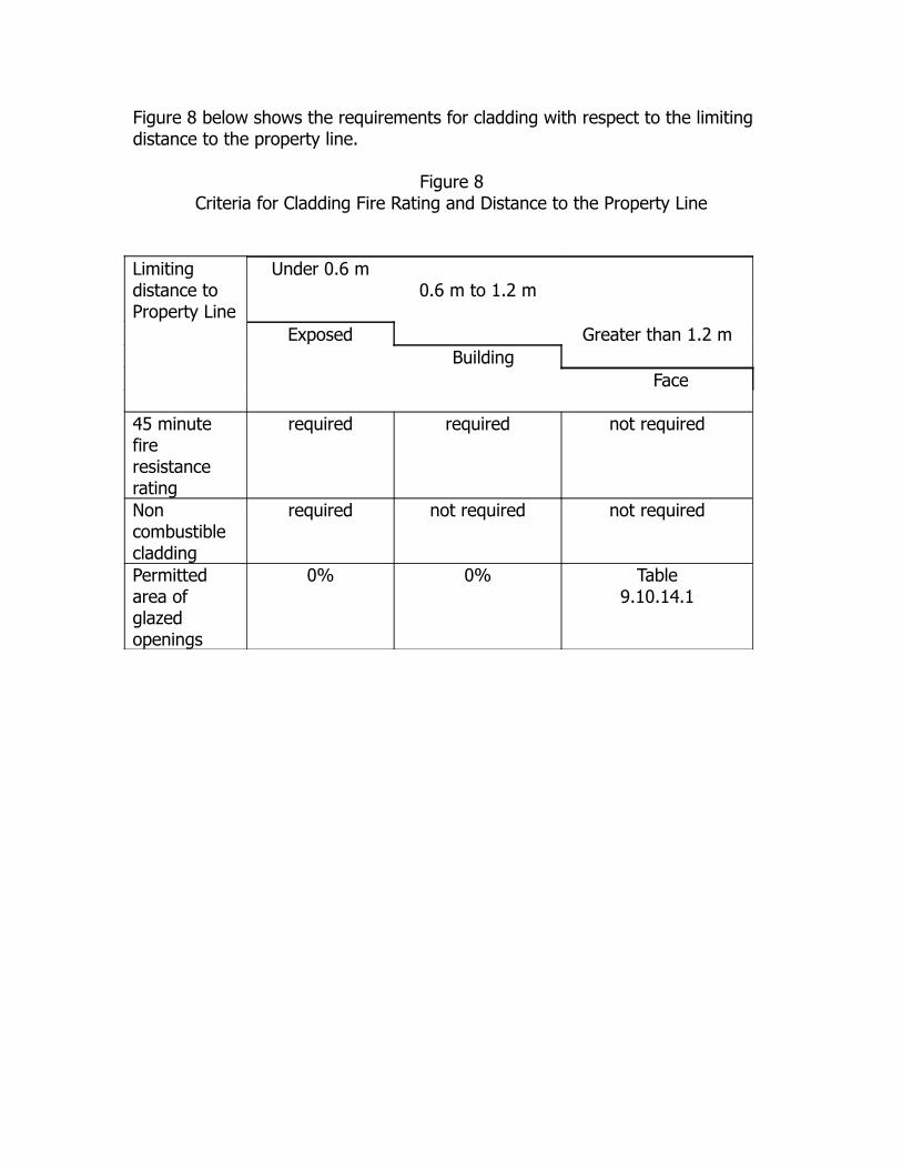
Figure 8 below shows the requirements for cladding with respect to the limiting distance to the property line.
Figure 8Criteria for Cladding Fire Rating and Distance to the Property Line
Limiting distance to Property Line
Under 0.6 m0.6 m to 1.2 m
Exposed Greater than 1.2 m Building
Face
45 minute fire resistance rating
required required not required
Non combustible cladding
required not required not required
Permitted area of glazed openings
0% 0% Table9.10.14.1
Thermal Resistance of Masonry - RSI (R) -Values
The RSI (R) - value is a measure of the Thermal Resistance of a material or wall assemblage. The units are RSI - m2.°C/W and R - ft2.h.°F/Btu . The Minimum Thermal Resistance of wall systems is 3.80 (R21) for Zone 1 in Ontario for gas heated building.
Typical value for thermal resistance of brick veneer is: RSI = 0.074 m2.°C/W , or R = 0.42 ft2.h.°F/Btu.
Brick veneer alone will not provide sufficient resistance to heat flow, and hence the need for insulation. However, the above figures are based on steady state heat flow and do not take into account the effect of “Thermal Mass”, i.e. the ability of the wall to absorb heat during the day and dissipate that heat in the night. Research carried out at the University of Waterloo, BEGHUT, indicates that a dark brick wall, particularly on the south or west wall, could result in significant savings (about 20%) in heating costs. Dark brick veneer will on average be 3-7°C above ambient temperature in the winter. BIA Tech Note 4B gives a conservative adjustment calculation, which takes into account the effect of Thermal Mass.

Sound Transmission Rating (STC)- Bldg. code Sect (9.11.2.1)
The specified STC rating of 50 is considered the minimum, but many builders prefer to design for STC 55. The code does not give values for brick. BIA Tech Note 5A gives STC values of 45 for a 95 mm (4 “) face brick wall and 50 for a 92 mm (4”) face brick wall and 13 mm (½“) plaster.
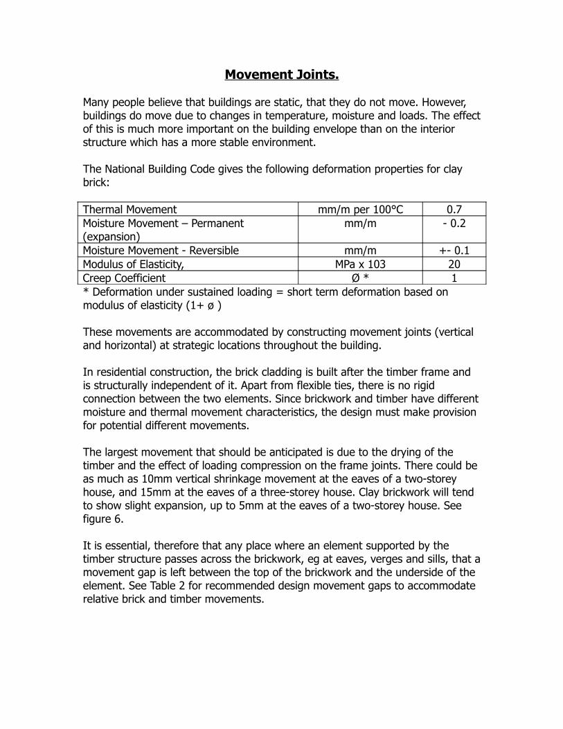
Movement Joints.
Many people believe that buildings are static, that they do not move. However, buildings do move due to changes in temperature, moisture and loads. The effect of this is much more important on the building envelope than on the interior structure which has a more stable environment.
The National Building Code gives the following deformation properties for clay brick:
Thermal Movement mm/m per 100°C 0.7Moisture Movement – Permanent (expansion)
mm/m - 0.2
Moisture Movement - Reversible mm/m +- 0.1Modulus of Elasticity, MPa x 103 20Creep Coefficient Ø * 1* Deformation under sustained loading = short term deformation based on modulus of elasticity (1+ ø )
These movements are accommodated by constructing movement joints (vertical and horizontal) at strategic locations throughout the building.
In residential construction, the brick cladding is built after the timber frame and is structurally independent of it. Apart from flexible ties, there is no rigid connection between the two elements. Since brickwork and timber have different moisture and thermal movement characteristics, the design must make provision for potential different movements.
The largest movement that should be anticipated is due to the drying of the timber and the effect of loading compression on the frame joints. There could be as much as 10mm vertical shrinkage movement at the eaves of a two-storey house, and 15mm at the eaves of a three-storey house. Clay brickwork will tend to show slight expansion, up to 5mm at the eaves of a two-storey house. See figure 6.
It is essential, therefore that any place where an element supported by the timber structure passes across the brickwork, eg at eaves, verges and sills, that a movement gap is left between the top of the brickwork and the underside of the element. See Table 2 for recommended design movement gaps to accommodate relative brick and timber movements.

Table 2 - Recommended Movement gaps.
Height Movement gapUp to 1st Floor 10 mmUp to 2nd Floor 15 mmUp to 3rd Floor 20 mm
Due to differential vertical movement characteristics, lintels for the brickwork are required to be independent of the timber frame. Similarly, door and window frames should not be fixed to the brickwork, although it is not likely to be a critical factor at ground level.
In addition to provisions for vertical movement, joints to accommodate horizontal movement are required in the brickwork cladding where there are long walls or short offsets less than 600mm. The CMCA recommends 10 mm wide expansion joints at 7-10m centres for clay brickwork. Such vertical joints can often be concealed behind rainwater pipes.

Sustainability
Masonry is one of the oldest building materials used by man and has been around for thousands of years and still the most widely used building material. The rich heritage of historic masonry buildings in Canada, Europe, Asia and other parts of the world bears testimony to the sustainability of masonry as a building material. This article looks at how a number of attributes of masonry contribute to sustainable design and construction. Some of these attributes are included in the LEED program; however, a number are not included in LEED. Table 4 at the end of this article lists the attributes and the applicable credits.
DurabilityMasonry units are durable and contribute to building assemblies that remain useful in the material cycle for long periods of time. The use of masonry units, if properly detailed, will minimize the risk and environmental costs of premature failure of building components. Most deterioration occurs to exterior wall components, therefore good building envelope design is essential. The Ontario Association of Architects (OAA) insurance plan only covers drained cladding systems or solid masonry or concrete systems that are moisture tolerant. Canada Standards Association (CSA) S478-95 (R2001) “Guidelines on Durability in Buildings” lists brick veneer with a design service life (DSL) of 50 years and concrete block firewalls with a DSL of 100 years. Masonry durability is recognized by OAA & CSA and should be part of building envelope design. Further, the Canadian version of LEED-NC gives a credit for Durability. Besides the durability of the materials used for construction, the actual assemblage of the wall system is fundamental in ensuring the durability of the building. An important aspect of the wall system is the presence of a drainage cavity or rainscreen wall system. The rainscreen wall system anticipates that water will get into the wall, either by permeating through the building materials, or by leakage through deficiencies in windows and other penetrations. The wall system is designed to direct this moisture back to the exterior. This drainage cavity is an important aspect of any wall system and is now a building code requirement for buildings in the high rainfall area (Moisture Index (MI) -greater than 1).
One of the best reasons for using masonry is its durability and potential for reuse and salvage. Most masonry units can be reused when carefully dismantled. In fact there is a significant market in Canada for reclaimed clay brick. However, the durability of the masonry units should be checked before reuse. Clay brick manufactured prior to 1950 was often fired in beehive kilns. Brick on the outer edges of the stack were under-fired and were lighter in colour (salmon). These brick did not have the durability of facing brick and were used on the inner wythe

of a multi-wythe brick wall. During demolition, it is important that these brick are kept separate from the facing brick.
Another aspect to consider when using reclaimed clay brick is the absorption characteristics of the bedding face, which may have been compromised by cement filling the voids. This can affect the potential bond between the mortar and the masonry unit. The initial rate of absorption (IRA) should also be checked before reuse to ensure a proper bond.
Because of the durability of masonry and masonry structures, masonry buildings are often ideal candidates for building reuse. Masonry also compares favourably with Life Cycle Analysis (LCA) that includes materials, construction and energy consumption.
Masonry is also resistant to other forms of degradation such as fire, mould and termites.Masonry is inherently fire resistant. Interior masonry fire partitions help stop the spread of fire. These aspects reduce the environmental impact of fires. Passive fire protection reduces the costs of buildings.
Masonry units are mould resistant and can be used in most environments where people work and live.
Structure / Finish CombinationMasonry can provide both structural support and the interior or exterior wall finish combination, which can reduce environmental and building costs. Both brick and block walls and columns have high structural load capacity. Most masonry structures are loaded to a fraction of their capacity. Furthermore, the face of masonry is visually attractive and does not need any coatings of finishes, whether installed in an exterior or interior application. LEED offers a credit where low VOC paints and sealers are used, but masonry does not need either, so VOCs are eliminated completely.
Masonry walls require very little maintenance, eliminating the need for regular upkeep and repairs and the associated cost and environmental impact.
Energy PerformanceThe mass of brick, block, natural and manufactured stone can provide thermal storage (also known as thermal mass) that can moderate a building’s temperature. Masonry can store heat energy and slowly release it, keeping the building cooler during the day and warmer at night. Thermal mass is more effective when used on the interior of a building and insulated to the outside. This is ideal for cooler climates. By using masonry in this way, the heating and cooling needs of the building are reduced and less energy is wasted.
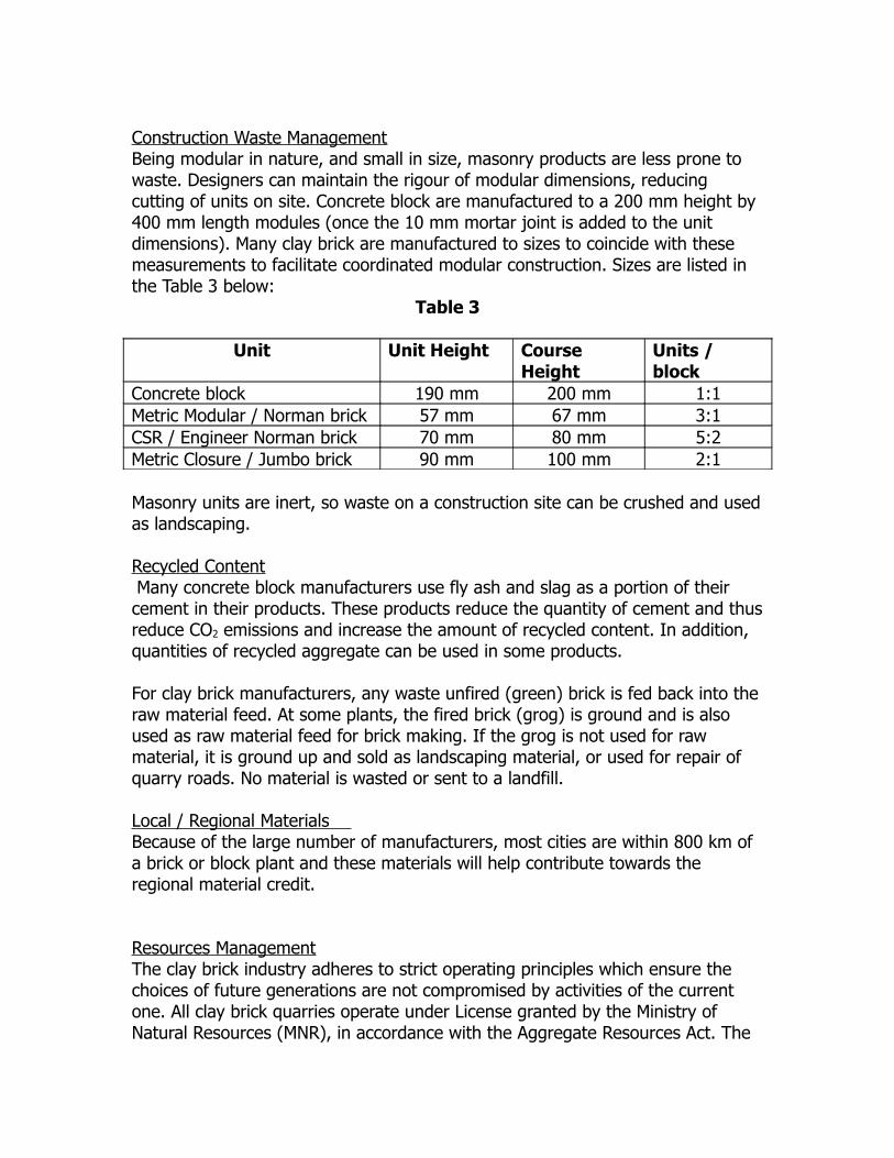
Construction Waste ManagementBeing modular in nature, and small in size, masonry products are less prone to waste. Designers can maintain the rigour of modular dimensions, reducing cutting of units on site. Concrete block are manufactured to a 200 mm height by 400 mm length modules (once the 10 mm mortar joint is added to the unit dimensions). Many clay brick are manufactured to sizes to coincide with these measurements to facilitate coordinated modular construction. Sizes are listed in the Table 3 below:
Table 3
Unit Unit Height Course Height
Units / block
Concrete block 190 mm 200 mm 1:1Metric Modular / Norman brick 57 mm 67 mm 3:1CSR / Engineer Norman brick 70 mm 80 mm 5:2Metric Closure / Jumbo brick 90 mm 100 mm 2:1
Masonry units are inert, so waste on a construction site can be crushed and used as landscaping.
Recycled Content Many concrete block manufacturers use fly ash and slag as a portion of their cement in their products. These products reduce the quantity of cement and thus reduce CO2 emissions and increase the amount of recycled content. In addition, quantities of recycled aggregate can be used in some products.
For clay brick manufacturers, any waste unfired (green) brick is fed back into the raw material feed. At some plants, the fired brick (grog) is ground and is also used as raw material feed for brick making. If the grog is not used for raw material, it is ground up and sold as landscaping material, or used for repair of quarry roads. No material is wasted or sent to a landfill.
Local / Regional Materials Because of the large number of manufacturers, most cities are within 800 km of a brick or block plant and these materials will help contribute towards the regional material credit.
Resources ManagementThe clay brick industry adheres to strict operating principles which ensure the choices of future generations are not compromised by activities of the current one. All clay brick quarries operate under License granted by the Ministry of Natural Resources (MNR), in accordance with the Aggregate Resources Act. The

License requires an approved Site Plan that typically contains operational, water, progressive and final rehabilitation plans, which are prepared in consultation with interested parties including the MNR, Conservation Authorities and local levels of government. Additional targets including control of dust and effluent discharge are set by the Ministry of Environment (MOE). Once mining operations at a quarry are complete, the land is carefully and meticulously backfilled and returned to a state as close as possible to the original, to ensure the land continues to offer future generations equivalent potential for use and development.
Quarries do impact the environment to a certain extent, but it is limited to the area of the quarry and is very controlled. The benefits of the quarry are significant. For example, a 200 acre quarry will be able to provide sufficient brick to clad approximately 10,000 houses (1.2 million sq. m. of wall area annually) or a total of around 500,000 houses over the life of the quarry. By contrast, one would need approximately 12,000 acres of farmland to produce enough straw bales to cover the same wall area.
The goal of the clay brick industry is to make clay mining operations environmentally neutral. In fact, from one perspective, the industry actually optimizes benefits from the land for current and future generations. If quarry land had actually been developed before the clay was mined, the mineral value of the land would be locked in and future generations would not have had the opportunity to access that clay. By extracting the clay, rehabilitating the land to pre-quarry use and then developing the land, the community has in fact achieved double the use of the valuable asset. Although the clay used to make brick is a very prevalent natural resource (existing resources will supply the needs of humans for thousands of years), brick manufacturers work diligently to ensure quarry sites are used responsibly and efficiently by developing them in a manner consistent with the criteria of the sustainability concept.
Reduced Environmental Impact of ManufactureAnother key criterion of sustainability is a reduction in the amount of energy required to produce building materials. Over the past 20 years, the clay brick industry has successfully committed to and accomplished a significant reduction in the energy needed to manufacture brick. In 2004, the energy required to manufacture one pound of material of clay brick is just over 50 percent of what it was in 1981. Since 2004, there has been a further reduction in energy use of about 10 percent due to improvements in the plants.
The dematerialization within the manufacturing process, also contributes to reducing energy consumption and the use of resources. In short, dematerialization translates into doing more with less. One of the goals of sustainability is to accomplish dematerialization without compromising the quality
or performance attributes of the product or project. The clay brick industry has achieved this in two ways:
Over the last two decades, the thickness of the brick veneer has gone from four inches to three and a half inches to three inches, and still maintaining the same level of performance
Investigating increasing the voids (cores) within the brick. Studies at the National Brick Research Centre (NBRC) at Clemson University, SC show that the Flexural bond strength, resistance to water penetration and compressive strength is not affected by increasing the voids up to 32 percent
With the increased use of scrubbers on new and old clay brick plants, the clay brick industry has aggressively reduced environmental emission and effluent throughout all steps in the manufacturing process. Ten years ago, approximately 52 percent of brick was manufactured from plants with scrubbers. Today that figure is 75 percent and expected to grow.
Since clay occurs naturally, it is virtually inert and remains so when formed into brick. Consequently, clay brick is the only cladding material that emits no gases, needs no maintenance and is impervious to chemical leaching. Moreover, brick is naturally fireproof and requires no coatings or cleaning products which could potentially produce environmentally harmful off gassing, or toxic fumes when burning.
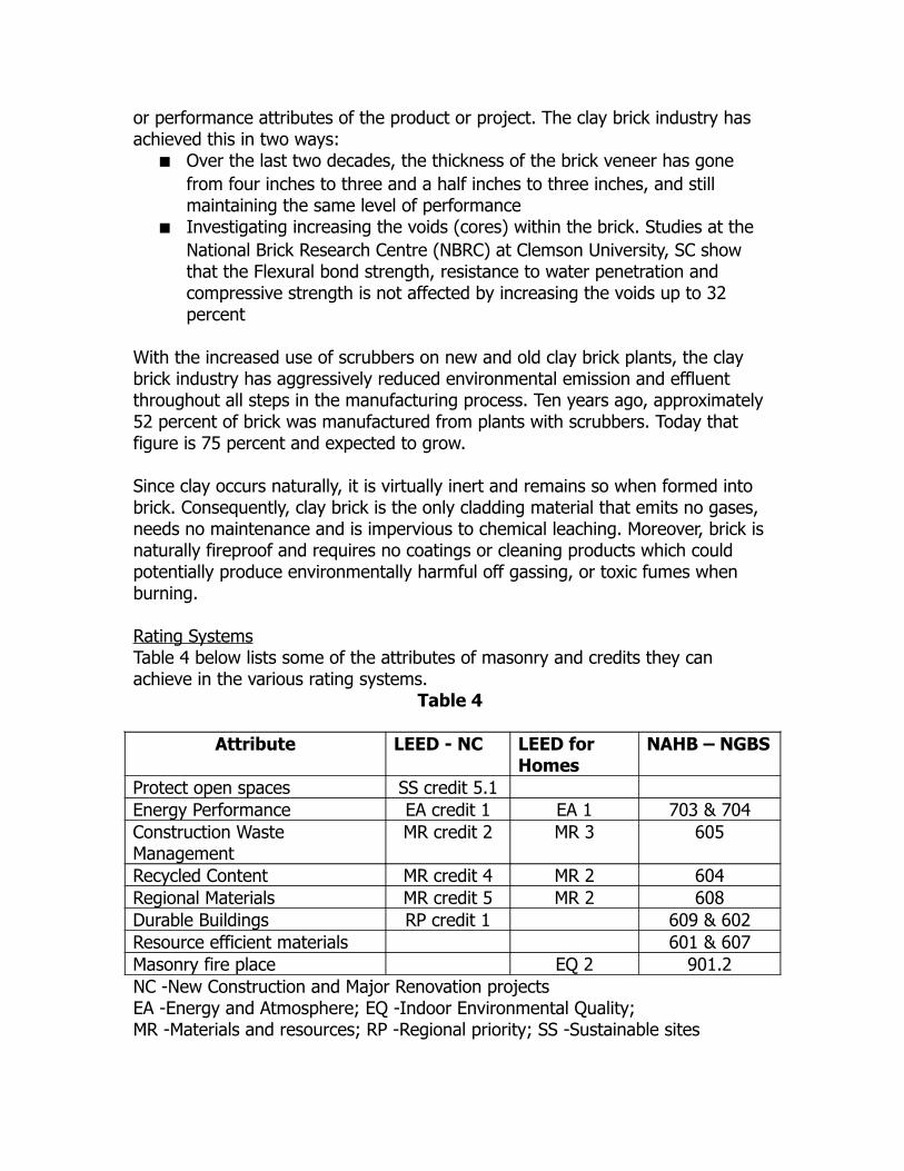
Rating SystemsTable 4 below lists some of the attributes of masonry and credits they can achieve in the various rating systems.
Table 4
Attribute LEED - NC LEED for Homes
NAHB – NGBS
Protect open spaces SS credit 5.1Energy Performance EA credit 1 EA 1 703 & 704Construction Waste Management
MR credit 2 MR 3 605
Recycled Content MR credit 4 MR 2 604Regional Materials MR credit 5 MR 2 608Durable Buildings RP credit 1 609 & 602Resource efficient materials 601 & 607Masonry fire place EQ 2 901.2NC -New Construction and Major Renovation projectsEA -Energy and Atmosphere; EQ -Indoor Environmental Quality; MR -Materials and resources; RP -Regional priority; SS -Sustainable sites
Cleaning of new masonry
It is often necessary to clean new masonry to achieve the desired aesthetics. The first step is for the mason to try and avoid getting mortar smears on the face of the brick. If there are mortar smears, the easiest cleaning method is to use clear water and a brush. This method needs to be carried out within 24 hour, before the mortar has had time to set. If the mortar has set, then cleaning can be achieved by using a proprietary cleaning agent, high pressure water or a combination of both. If either of these methods is used, the cleaning should be carried out between 7 and 30 days of installation. Seven days allows the mortar to gain sufficient strength so that the mortar is not damaged during cleaning. If the mortar is allowed to set for more than 30 days, it becomes progressively more difficult to remove.
If a proprietary cleaning agent is used, it is important that the brickwork is prewet so that the cleaning agent remains on the surface of the brickwork where it is most effective. Check with your brick manufacturer for recommendations on what cleaner is best suited for their product.
If high pressure water is used, then the pressure should not exceed 4850 kPa (700 psi) at a 2 ft. minimum distance. Also use a fan nozzle with a spray angle of at least 60º. Use gentle strokes.
As with all masonry cleaning projects, it is important to carry out the cleaning on an inconspicuous area of brickwork first to ensure that the desired results are achieved. Allow a day or two for the brickwork to dry before inspection. If the desired are achieved, proceed with cleaning the rest of the brickwork.
For more information on cleaning of masonry, see BIA Technical Note 20.

Efflorescence
Efflorescence is a white crystalline deposit left on the surface of masonry. It is a very complex process whose occurrence is very difficult to predict.
In new masonry construction when efflorescence is observed it is called new building bloom. In most cases, new building bloom will dissipate over time if the brickwork is allowed to dry after completion and if environmental factors such as wind and rain are given sufficient time to naturally clean the brick work. There are several factors that contribute to new building bloom. These include:
High moisture levels in the wall: This can be caused by walls under construction being exposed to rain, concentrated moisture at contact with grade and under horizontal elements such as sills and caps and sheet drainage from non-absorptive surfaces. The moisture will dissolve soluble elements of the wall and bring them to the surface.
Cement reactions: One of the main soluble elements is calcium hydroxide. It is found in all cement-bearing materials. It is a product of the cement hydration process. The calcium hydroxide reacts with CO2 in the air to form calcium carbonate, which is a white powder.
Reaction between the brick and mortar: The calcium hydroxide in the mortar can react with trace elements in the brick to form efflorescence as well.
Temperature: Calcium hydroxide becomes more soluble when the temperature decreases with maximum solubility reached at 40 °F. This is why efflorescence is more prevalent in the spring and fall.
If more immediate removal of efflorescence is required, it can be removed by scrubbing with a bristle brush and clean water. Cleaning of efflorescence should only take place once the efflorescence has ceased. If the brickwork is cleaned while the efflorescence is still occurring, it will continue to effloresce and will need to be cleaned again. As most means of cleaning efflorescence use water, it is not recommended to clean the efflorescence during cold months (Oct to Mar), as this will add more moisture into the brickwork increasing the risk of more efflorescence.
If efflorescence occurs in an older building, it is an indication that excess moisture is getting into the masonry. The best method of addressing this is to identify the source of the moisture and correct the offending detail. Once this has been done, the efflorescence can be removed.
CSA Standard A82-06 requirements
CSA Standard A82-06 “Fired masonry units made from clay or shale” sets down the requirements for manufacture of clay brick in Canada. The previous version of this standard is A82.1-M87 “Burned clay brick, manufactured from clay of shale’. This latter standard is the one that is referenced by the current building codes. The other CSA masonry standards refer to the former more recent standard. Architects and engineers are at liberty to specify a newer standard.
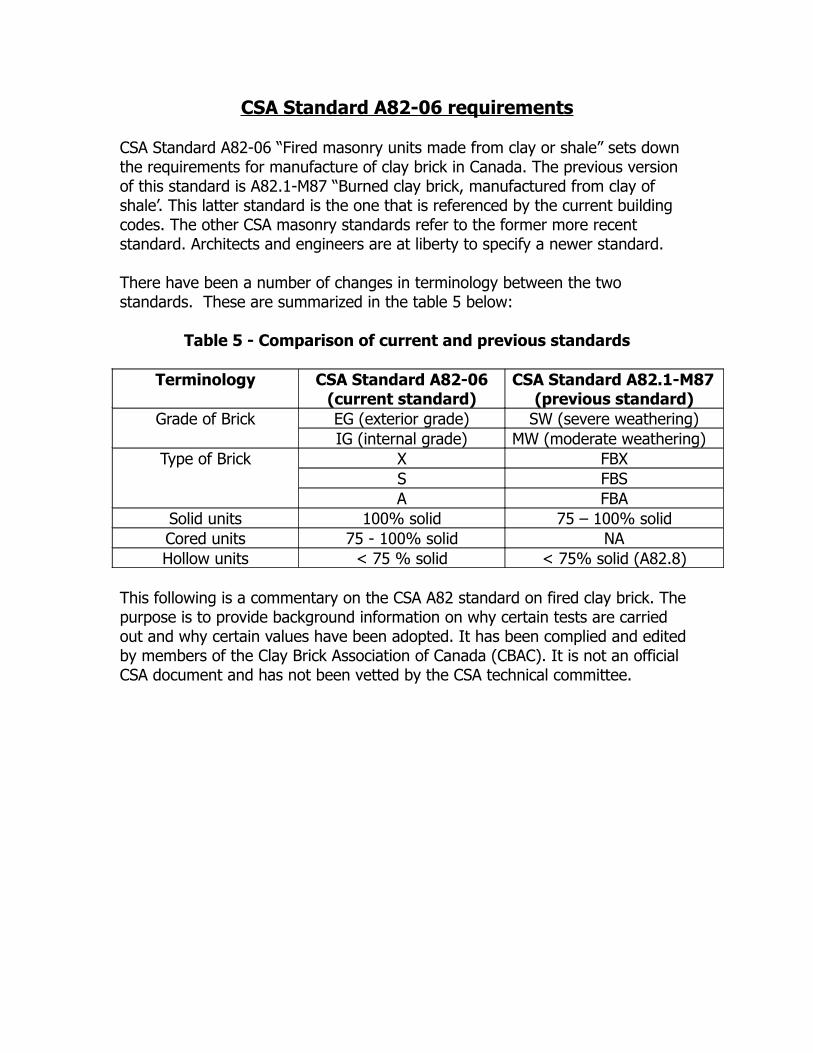
There have been a number of changes in terminology between the two standards. These are summarized in the table 5 below:
Table 5 - Comparison of current and previous standards
Terminology CSA Standard A82-06(current standard)
CSA Standard A82.1-M87(previous standard)
Grade of Brick EG (exterior grade) SW (severe weathering)IG (internal grade) MW (moderate weathering)
Type of Brick X FBXS FBSA FBA
Solid units 100% solid 75 – 100% solidCored units 75 - 100% solid NAHollow units < 75 % solid < 75% solid (A82.8)
This following is a commentary on the CSA A82 standard on fired clay brick. The purpose is to provide background information on why certain tests are carried out and why certain values have been adopted. It has been complied and edited by members of the Clay Brick Association of Canada (CBAC). It is not an official CSA document and has not been vetted by the CSA technical committee.
Freeze-thaw test
Clay brick is one of the most durable building products available. However, clay brick can be susceptible to damage (spalling) if they are subjected to freeze-thaw cycles in a saturated condition. This condition does not take place in properly designed masonry veneer (see BIA Tech Notes 7, 7A, 7B) but can occur due to improper masonry design or workmanship or if sealants are applied to the face of the brick. At a certain level of saturation and when exposed to repetitive freeze-thaw cycles, the expansion of the ice in the pore structure of the brick can lead to damage.
The freeze-thaw test is used to determine the brick’s capacity to resist damage during freezing and thawing. In the test, the brick is subjected to fifty cycles of 20 hours of freezing followed by four hours of thawing. At the end of the test, the units must not have lost more than 0.5% of their mass, nor have broken, or developed visible cracks.
After a 15 year joint CBAC-NRC research program, a number of changes were incorporated into the 2006 Standard, where the severity of the test was increased, by ensuring that the brick remains in a frozen state during any interruptions in the testing. Previously the standard allowed the brick to drain (air dry) during these periods such as weekend. The saturation level of the samples continuously increases dramatically increasing the severity of this test. This test takes approximately 10 to 12 weeks to complete.
The results of the freeze-thaw test take precedence over those of the absorption procedures, where the absorption properties do not meet the requirements shown below.
Absorption tests
Because the freeze-thaw tests take up to three months to complete, they are not practical as a quality control test, the absorption tests were developed which have a strong correlation to freeze-thaw durability and the freeze-thaw tests. These tests include:Cold water absorption (C) - Dry brick are placed in water for 24 hours and the percentage moisture absorbed is recorded as the % Cold Water Absorption.Boiling water absorption (B) - After the cold water absorption test is complete, the same brick are then placed in water and brought to a boil and held for a period of 5 hours and the total percentage moisture absorbed is measured.Saturation Coefficient (C/B) -The saturation coefficient is calculated as the ratio of the cold water absorption over the boiling water absorption. It is also known as the CB Ratio.
The standard sets the following upper limits for each of these tests:
C less than 8% and B less than 17 % or;
C/B less than 0.78 and B less than 17 %
Note that to comply with the standard, the brick must satisfy the requirement of either cold water or the saturation coefficient criteria. The reason for this is that the various clay bodies have different properties and that the criteria that ensures durability of one clay body may not be applicable to another.For a particular clay body, the more it is fired in the kiln, the lower the absorbency and the higher the durability. However, for the same level of durability, the darker brick tend to have lower absorbencies and the lighter coloured brick tend to have higher absorbencies.
The rationale behind the saturation coefficient is as follows:
The cold water absorption reflects the amount of water which the brick will take up in wet field conditions in properly designed and detailed veneer walls.The boiling water absorption reflects the maximum volume of voids which can be filled with water. If the brick has a saturation coefficient of less than 0.78, it means that even if the brick is saturated in field conditions when subjected to freezing, there is still 22% of the voids unfilled which allows the ice to expand into these voids without damaging the brick structure.
Compressive strength test
In this test, the brick is subjected to a compressive force until failure and the failure load over gross area is recorded as the strength. Originally, the compressive strength was considered an important indicator of durability as it is a measure of the fired bond strength in the brick. However, the compressive strength is no longer considered as a critical indicator of durability, but it is used in determining the load-bearing capacity of the masonry.
In order to achieve the above absorption levels, the brick has to be fired extremely hard and the resultant compressive strength of the units is several times higher than the standard requires. Also, in most applications, the stresses that the brick is subjected to, is very low, well below the strength of the unit.
Initial Rate of Absorption (IRA)
In this test, the bedding face of the brick is placed in a shallow tray of water for a period of one minute and the amount of water absorbed in calculated as in g/(min. x 20 000 mm2). The IRA is an indication of the potential bond between the brick unit and the mortar.
The brick does require a certain absorption range in order to draw the water and cement into the surface voids and create a mechanical bond. If the IRA is too low, the lack of absorption can inhibit bond development. If the absorption is too high, the unit will draw the water out of the mortar too quickly, causing the mortar to lose plasticity and inhibit its strength and the bond development of the mortar.
The IRA is an optional test and is not a requirement of the standard because there are more factors on site that can affect the IRA than simply the properties of the brick. Corrective measures for brick with low IRA and or cold weather may include:
Using type S mortar or increase amount of lime in mortar Keep brick dry and warm prior to installation Increase time between laying of the units and tooling
Corrective measures for brick with high IRA or hot weather may include: Pre-wet the units and/or keep them in shade prior to laying Use admixtures which increase water retentivity

Finish
Clay brick can be either “through-the-body” colour (where the colour on the face is the same as the clay body), or a clay brick can get its colour from a coating on the exterior faces only. Some extruded brick will have all or some of the following surface treatment applied to the face and headers of the brick prior to firing; texturing, engobe and/or coloured sand coating. This treatment enables manufacturers to provide a wide range of brick styles and appearances.
Some brick may exhibit surface defects. The following are some of the surface defects that can be present on a brick:
Chips - Although every endeavor is made by the manufacturer to ensure that all brick delivered to a site is free of chips, chips can occur as a result of handling, transportation or during installation. The standard does make an allowance for these chips. (see Table 8 below)
Hairline cracks -Clay brick are fired at temperatures in excess of 1000ºC. As the brick expand and contracts during the firing process, hairline cracks can sometime develop on the face or back of the brick.
These imperfections do not affect the integrity or durability of the brick. Masonry should be judged on its overall aesthetics rather than a close scrutiny of the individual units. The CSA A82 Standard states that those imperfections that are not visible from a distance of 4.5m (15 feet) for type X brick and 6.1 m (20 feet) for type S or A, are acceptable.
Efflorescence test
For this test, five brick are placed in a shallow tray of water for a week. The brick are then dried and compared with a control set of brick to determine whether or not there is efflorescence. Brick are rated as “no efflorescence”, “slightly effloresced” or “effloresced”. The first two categories are acceptable. This test is optional, because there are more factors on site which can contribute to efflorescence than the properties of the brick. Some of the factors on site which can affect efflorescence are; moisture content of the masonry at installation, adjacent materials, mortar composition, whether or not the masonry walls are covered during work stoppages, freezing during construction, exposure of the walls to runoff from slab or roof above.
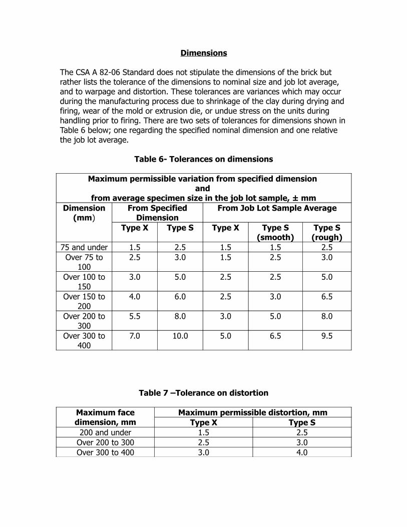
Dimensions
The CSA A 82-06 Standard does not stipulate the dimensions of the brick but rather lists the tolerance of the dimensions to nominal size and job lot average, and to warpage and distortion. These tolerances are variances which may occur during the manufacturing process due to shrinkage of the clay during drying and firing, wear of the mold or extrusion die, or undue stress on the units during handling prior to firing. There are two sets of tolerances for dimensions shown in Table 6 below; one regarding the specified nominal dimension and one relative the job lot average.
Table 6- Tolerances on dimensions
Maximum permissible variation from specified dimension and
from average specimen size in the job lot sample, ± mmDimension
(mm)From Specified
DimensionFrom Job Lot Sample Average
Type X Type S Type X Type S (smooth)
Type S (rough)
75 and under 1.5 2.5 1.5 1.5 2.5Over 75 to
1002.5 3.0 1.5 2.5 3.0
Over 100 to 150
3.0 5.0 2.5 2.5 5.0
Over 150 to 200
4.0 6.0 2.5 3.0 6.5
Over 200 to 300
5.5 8.0 3.0 5.0 8.0
Over 300 to 400
7.0 10.0 5.0 6.5 9.5
Table 7 –Tolerance on distortion
Maximum face dimension, mm
Maximum permissible distortion, mmType X Type S
200 and under 1.5 2.5Over 200 to 300 2.5 3.0Over 300 to 400 3.0 4.0

Table 8 -Tolerance on chippage
TypeMaximum allowed,
% *
Chippagein from Edgemm
Chippage in from Corner,
mm
Remaining allowed,
% *
Chippagein fromEdge,mm
Chippage in from Corner,
mm
X 5 or less 3.0-6.5 6.5-9.5 95-100 0-3.0 0-6.5
S(plain)** 10 or less 6.5-8.0 9.5-13.0 90-100 0-6.5 0-9.5
S(textured)***
15 or less 8.0-11.0 13.0-19.0
85-100 0-8.0 0-13.0
A As specified
*Percentage of exposed brick in the job lot permitted to have chippage extending from an edge or corner to the dimensions in this Table.
Of all the brick that will be exposed in place, a small percentage of the brick may have chips that range in size greater than that allowed for the majority of the brick. This special allowed percentage, as shown in the “Maximum allowed, %” columne, ranges up to 5% for X, up to 10% for S (plain), and up to 15% for S (textured). The remainder of the brick that will be exposed in place, as shown in the “Remaining allowed, % column, shall conform to the maximum allowed chippage shown in the last two columns of this Table.
** Plain brick are dry-pressed brick or extruded brick with an inbroken natural die finish face.*** Textured brick are moulded brick or extruded brick with the face sanded, combed, engobed, scratched, or scarified, or the die skin on the face entirely broken by mechanical means such as wire cutting or wire brushing.
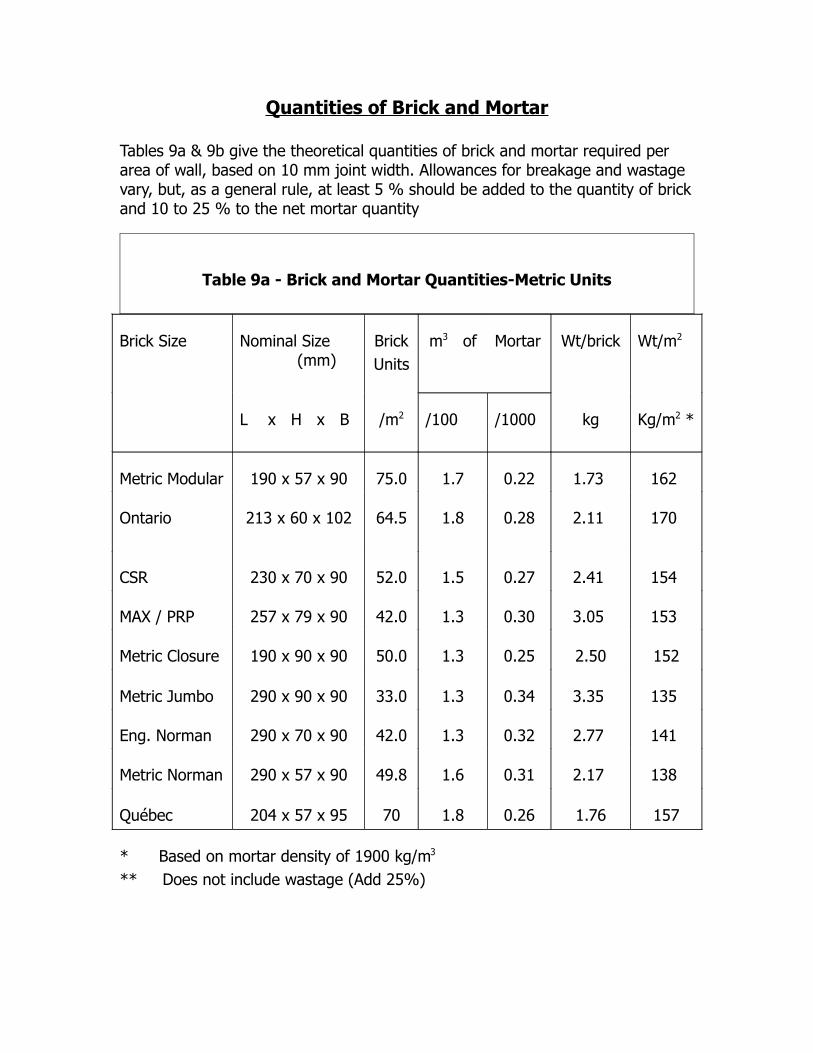
Quantities of Brick and Mortar
Tables 9a & 9b give the theoretical quantities of brick and mortar required per area of wall, based on 10 mm joint width. Allowances for breakage and wastage vary, but, as a general rule, at least 5 % should be added to the quantity of brick and 10 to 25 % to the net mortar quantity
Table 9a - Brick and Mortar Quantities-Metric Units
Brick Size Nominal Size (mm)
BrickUnits
m3 of Mortar Wt/brick Wt/m2
L x H x B /m2 /100 /1000 kg Kg/m2 *
Metric Modular 190 x 57 x 90 75.0 1.7 0.22 1.73 162
Ontario 213 x 60 x 102 64.5 1.8 0.28 2.11 170
CSR 230 x 70 x 90 52.0 1.5 0.27 2.41 154
MAX / PRP 257 x 79 x 90 42.0 1.3 0.30 3.05 153
Metric Closure 190 x 90 x 90 50.0 1.3 0.25 2.50 152
Metric Jumbo 290 x 90 x 90 33.0 1.3 0.34 3.35 135
Eng. Norman 290 x 70 x 90 42.0 1.3 0.32 2.77 141
Metric Norman 290 x 57 x 90 49.8 1.6 0.31 2.17 138
Québec 204 x 57 x 95 70 1.8 0.26 1.76 157
* Based on mortar density of 1900 kg/m3
** Does not include wastage (Add 25%)
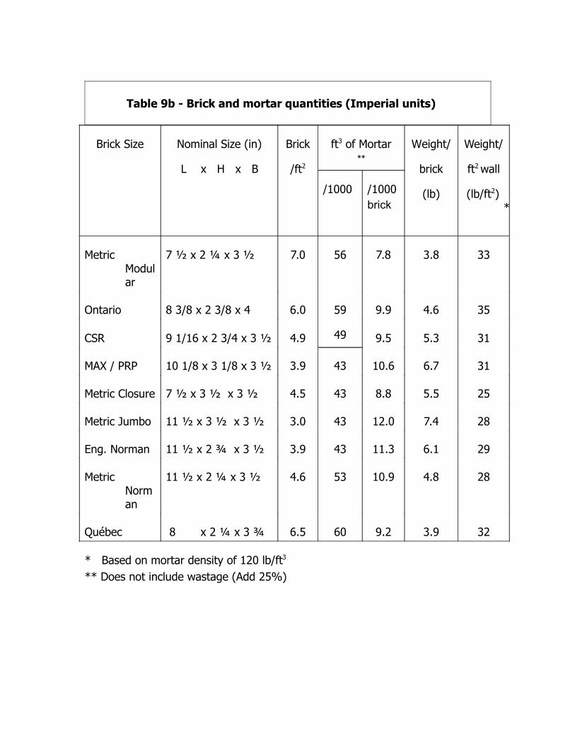
Table 9b - Brick and mortar quantities (Imperial units)
Brick Size Nominal Size (in)
L x H x B
Brick
/ft2
ft3 of Mortar**
Weight/
brick
(lb)
Weight/
ft2 wall
(lb/ft2) *
/1000 /1000brick
Metric Modular
7 ½ x 2 ¼ x 3 ½ 7.0 56 7.8 3.8 33
Ontario 8 3/8 x 2 3/8 x 4 6.0 59
49
9.9 4.6 35
CSR 9 1/16 x 2 3/4 x 3 ½ 4.9 9.5 5.3 31
MAX / PRP 10 1/8 x 3 1/8 x 3 ½ 3.9 43 10.6 6.7 31
Metric Closure 7 ½ x 3 ½ x 3 ½ 4.5 43 8.8 5.5 25
Metric Jumbo 11 ½ x 3 ½ x 3 ½ 3.0 43 12.0 7.4 28
Eng. Norman 11 ½ x 2 ¾ x 3 ½ 3.9 43 11.3 6.1 29
Metric Norman
11 ½ x 2 ¼ x 3 ½ 4.6 53 10.9 4.8 28
Québec 8 x 2 ¼ x 3 ¾ 6.5 60 9.2 3.9 32
* Based on mortar density of 120 lb/ft3
** Does not include wastage (Add 25%)