Embed Size (px)
Citation preview
1
Sixth International Symposium on Cavitation
CAV2006, Wageningen, The Netherlands, September 2006
CAVITATION IN KÁRMÁN VORTICES AND FLOW INDUCED VIBRATIONS
Ausoni Philippe Ecole polytechnique fédérale de Lausanne, Laboratory for Hydraulic Machines, Avenue de Cour 33bis, 1007 Lausanne, Switzerland
email: [email protected] Phone: +41 21 693 42 78 Fax: +41 21 693 35 54
Farhat Mohamed Ecole polytechnique fédérale de Lausanne, Laboratory for Hydraulic Machines, Avenue de Cour 33bis, 1007 Lausanne, Switzerland
Escaler Xavier Universitat politecnica de catalunya, Center for Industrial Diagnostics, Avenidad Diagonal 647, 08028 Barcelona, Spain
Avellan François Ecole polytechnique fédérale de Lausanne, Laboratory for Hydraulic Machines,
Avenue de Cour 33bis, 1007 Lausanne, Switzerland
ABSTRACT
The shedding process of the Kármán vortices at the trailing edge of a 2D hydrofoil at high Reynolds numbers is investigated. The focus is put on the effect of the cavitation on the vortex street morphology. A direct insight is also provided on the role of the structural vibration on the cavitation inception.
The shedding frequency, derived from the measurement of flow induced vibration, is found to follow the Strouhal law as far as none of resonance frequencies of the hydrofoil is excited. For lock-off condition, PIV measurements in cavitation free regime and high speed visualizations for developed cavitation reveal strong spanwise 3D instabilities. The comparison of instantaneous velocity fields in cavitation free regime and images of cavitating vortices does not show notable influence of the cavitation on the vortex street morphology. It is also observed that the cavitation inception index increases linearly with the square root of the Reynolds number. For Reynolds numbers ranging from 35’000 to 40’000, the torsion mode of the hydrofoil is excited with a substantial increase of the vibration level. In this case, the spatial coherence of the Kármán vortices is enhanced with a quasi 2D shape and the shedding frequency is locked onto the vibration frequency. The cavitation inception index is found to be significantly increased compared to lock-off conditions. It is thought that the vortex roll-up is amplified by the phase locked vibration of the trailing edge. Former model, successful in describing the cavitation inception for fixed bluff bodies, is extended for taking into account the hydrofoil trailing edge vibration velocity. In addition, we have found that the vortices strength increases for lock-in condition and is directly related to the vibration velocity of the trailing edge normalized by the upstream velocity.
INTRODUCTION
Vortex shedding is a dominant feature of two-dimensional body wakes. Although the wakes have been extensively studied for flow around cylinders or wedges, only few experimental works are related to the effect of cavitation on the Kármán vortex shedding process. It is known that the cavitation is not a passive agent for the visualization of the turbulent wake flow. But as matters stand, the influence of the cavitation on the wake morphology has remained unclear. The role of the cavitation in vortices 3D aspect is indeed an open question. The wake cavitation inception is also investigated. The role of the structural vibration on both the cavitation inception and vortex strength is pointed out.
Placed in a fluid stream, bluff bodies generate
separated flow over a substantial proportion of their surface that extends to their wake. The detachment of the boundary layers on both upper and lower surfaces forms two shear layers generating, above critical values of Reynolds number, a periodic array of discrete vortices termed Kármán street. In a range of upstream velocity, the vortex shedding frequency is known to follow the Strouhal law. From a hydrodynamic point of view, the instability of the shear layer separating from a circular cylinder has been extensively investigated; see Williamson [14] for a comprehensive review. Many authors observe that the wake structure may exhibit 3D aspect even if the obstacle and the upcoming flow are 2D. Gerrard [7] observes curved vortices and suspects that the cylinder end conditions might be the cause. Gerich et al. [5], Prasad et al. [10] and Williamson [13] find that the spanwise end conditions control the primary
2
vortex shedding and significantly affect the stability of the separating shear layer.
Vortex induced vibration and fluid-structure interaction phenomena have been the issue of many researches, which Rockwell [11] and Williamson et al. [15] have reviewed. It is well known that the bodies which shed spanwise vortices may be excited into oscillation by the fluctuating side forces that such vortices produce. For instance, the resonance occurs when the vortex shedding frequency coincides with one of the eigen frequencies of the combined fluid-structure system. In the case where the response amplitude becomes sufficiently large, the structural displacement can control the fluid excitation leading to the so-called “lock-in” phenomenon. The vortex shedding frequency is therefore “locked” onto the structural eigen frequency on a free velocity range. With large structural displacement, the vortex strength is increasing as well as the periodic forces. And with the axial correlation of vorticity increasing, the periodic forces are further increased. Davies [4] compares the wake structure of a stationary and oscillating bluff body. The results show an increase of 35% in the circulation of vortices shed from the oscillating cylinder, compared with those in the wake of a stationary body. Gilbert et al. [8] investigate the influence of the structural vibration on the vortex street morphology. They visualize hydrogen bubble flow of a self-oscillating cylinder vortex street “void”. Interestingly, “void” do not originate at nodes in the cylinder’s vibration; they are seen to appear where the cylinder is vibrating at amplitudes that appear to be a large fraction of the cylinder diameter.
When the pressure is low enough, bubbles filled with vapour and gas are initiated and persist in the centre of individual shed vortices. Sridhar et al. [12] investigate the effect of entrained bubbles on the structure of vortex rings. They demonstrate that a few microscopic bubbles fragment the core of the vortex into two regions with peak vorticities that are 20% higher than the original maximum vorticity. Young et al. [16] and Belahadji et al. [3] investigate the case of a flow around wedges. They observe that the cavitation development in the wake increases the shedding frequency by up to 25% and therefore affects the dynamic of the Kármán street. Models for cavitation inception in the wake of bluff bodies have been presented by Belahadji et al. [3], Arndt [1] and Pauchet et al. [9]. All models lead to a linear law between the cavitation inception index and the Reynolds number. Although remarkably successful in describing the cavitation inception for fixed bluff bodies, none of this study provides a direct insight into the role of the trailing edge vibration on the cavitation occurrence.
In this paper, the experimental setup and the
measuring techniques are first presented. The following section is devoted to the experimental results of the fluid-structure interaction in cavitation free regime: The flow induced vibration is evidenced as well as the lock-in and the corresponding eigen mode. Through PIV measurements, the wake morphology is revealed for both
lock-in and lock-off condition. The next section studies the flow induced vibration influence on cavitation inception: A direct insight is provided into the role of the hydrofoil trailing edge vibration. The cavitation development for both lock-off and lock-in conditions are finally presented through wake visualizations and flow induced vibration analysis. The paper conclusions are summarized in the last section.
NOMENCLATURE
( , , )z sA f x y Hydrofoil vibration amplitude for the
frequency fs at coordinates (x,z) [m] 'zA Hydrofoil vibration velocity [m/s]
b Hydrofoil span [m]
C Absolute velocity [m/s]
Cref Reference velocity at the test section inlet
[m/s]
fs Vortices shedding frequency [Hz]
ft Hydrofoil torsion eigen frequency [Hz]
l Hydrofoil chord length [m]
pinlet Reference pressure at the test section inlet
[bar]
pv Vapour pressure [bar]
Reh Reynolds number [-] Reh=Crefh/υ
St Strouhal number [-] St=fs h/Cref
h Hydrofoil trailing edge thickness [m]
α Incidence angle of the hydrofoil [°]
σ Cavitation index [-] σ=2(pinlet-pv)/ρCref2
σi Cavitation inception index [-]
υ Kinematic viscosity [m2/s]
3
EXPERIMENTAL SETUP The EPFL high-speed cavitation tunnel, outlined on
Figure 1, is a closed loop with a test section of 150x150x750 mm, Avellan et al. [2]. The operating flow parameters are the upstream velocity Cref, the cavitation index σ and the hydrofoil incidence angle α.
Figure 1 : EPFL high speed cavitation tunnel
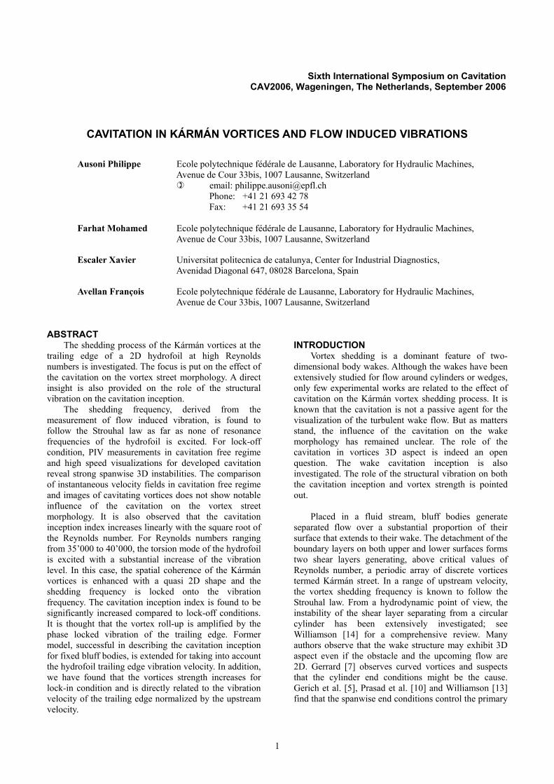
The experimental 2D hydrofoil, sketched on Figure
2, is a blunt truncated Naca 0009 made of stainless steel. The trailing edge thickness h is 3.22 mm and its chord length L and span b are 100 mm and 150 mm respectively. The hydrofoil mounting in the test section can be considered as a perfect embedding on one side and pivot embedding on the other. For all the measurements, the incidence angle of the hydrofoil α is fixed at 0° and the cavitation index is set high enough to allow cavitation occurrence only in the wake and not on the hydrofoil surface.
Figure 2 : Blunt truncated Naca 0009 hydrofoil
The flow induced vibrations are measured with the
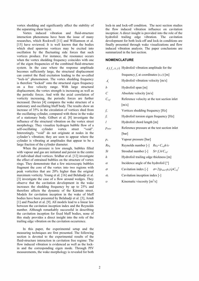
help of an accelerometer and a laser vibrometer. The piezoelectric accelerometer, whose resonance frequency is 54 kHz, is fitted on the profile support and a portable laser vibrometer is used to survey the hydrodoil surface vibrations. The measurement principle of the laser vibrometer is based on the detection of the frequency shift of the reflected laser beam according to the Doppler effect; the frequency shift being directly related to the displacement velocity of the surface in the laser direction. The location of the vibration amplitude measurements points is shown in Figure 3. Hydrofoil vibration measurements are synchronised with the accelerometer signal used as the reference. The amplitude and the phase of the hydrofoil motion at each measurement point are obtained and the eigen mode is identified for the detected hydro-elastic coupling.
The data acquisition system has 16 bits A/D resolution, 16 inputs, a memory depth of 1 MSamples/Channel and a maximum sampling frequency of 51.2 kHz/Channel
Figure 3 : Location of the hydrofoil vibration amplitude
measurements points
The vortical structures in the wake are visualized with the help of a high speed digital camera. The CCD image resolution is 512x256 pixels at 12’500 frames/sec.
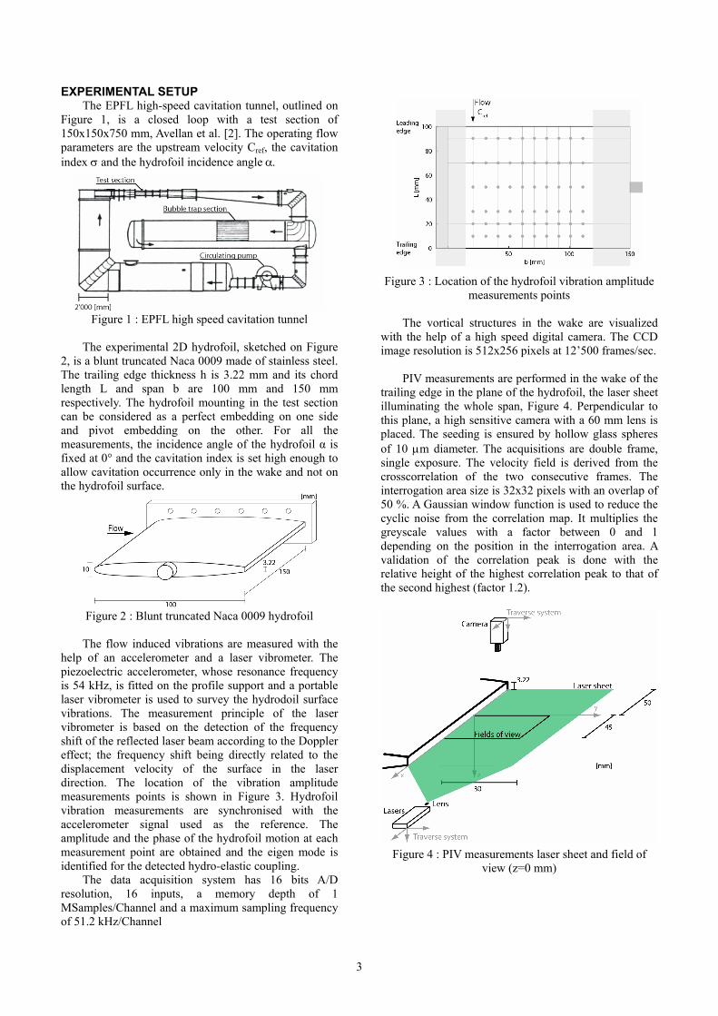
PIV measurements are performed in the wake of the
trailing edge in the plane of the hydrofoil, the laser sheet illuminating the whole span, Figure 4. Perpendicular to this plane, a high sensitive camera with a 60 mm lens is placed. The seeding is ensured by hollow glass spheres of 10 μm diameter. The acquisitions are double frame, single exposure. The velocity field is derived from the crosscorrelation of the two consecutive frames. The interrogation area size is 32x32 pixels with an overlap of 50 %. A Gaussian window function is used to reduce the cyclic noise from the correlation map. It multiplies the greyscale values with a factor between 0 and 1 depending on the position in the interrogation area. A validation of the correlation peak is done with the relative height of the highest correlation peak to that of the second highest (factor 1.2).
Figure 4 : PIV measurements laser sheet and field of
view (z=0 mm)
4
FLUID STRUCTURE INTERACTION IN CAVITATION FREE REGIME
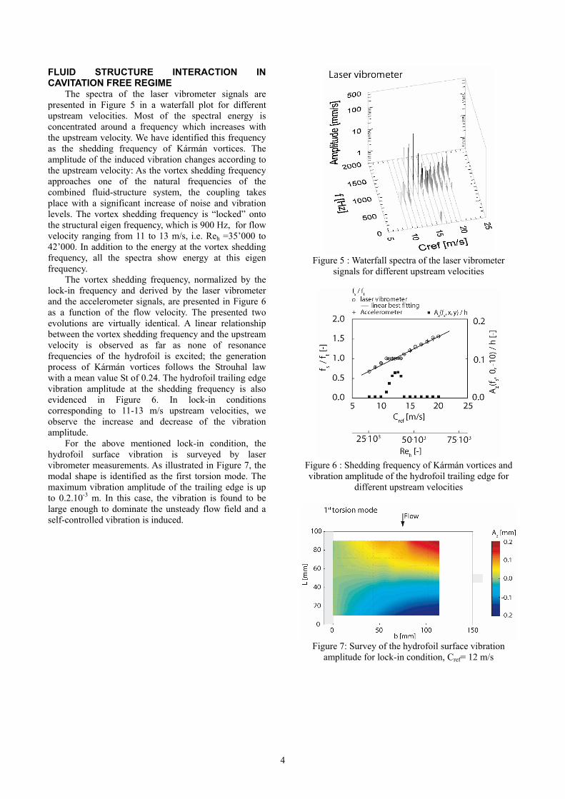
The spectra of the laser vibrometer signals are presented in Figure 5 in a waterfall plot for different upstream velocities. Most of the spectral energy is concentrated around a frequency which increases with the upstream velocity. We have identified this frequency as the shedding frequency of Kármán vortices. The amplitude of the induced vibration changes according to the upstream velocity: As the vortex shedding frequency approaches one of the natural frequencies of the combined fluid-structure system, the coupling takes place with a significant increase of noise and vibration levels. The vortex shedding frequency is “locked” onto the structural eigen frequency, which is 900 Hz, for flow velocity ranging from 11 to 13 m/s, i.e. Reh =35’000 to 42’000. In addition to the energy at the vortex shedding frequency, all the spectra show energy at this eigen frequency.
The vortex shedding frequency, normalized by the lock-in frequency and derived by the laser vibrometer and the accelerometer signals, are presented in Figure 6 as a function of the flow velocity. The presented two evolutions are virtually identical. A linear relationship between the vortex shedding frequency and the upstream velocity is observed as far as none of resonance frequencies of the hydrofoil is excited; the generation process of Kármán vortices follows the Strouhal law with a mean value St of 0.24. The hydrofoil trailing edge vibration amplitude at the shedding frequency is also evidenced in Figure 6. In lock-in conditions corresponding to 11-13 m/s upstream velocities, we observe the increase and decrease of the vibration amplitude.
For the above mentioned lock-in condition, the hydrofoil surface vibration is surveyed by laser vibrometer measurements. As illustrated in Figure 7, the modal shape is identified as the first torsion mode. The maximum vibration amplitude of the trailing edge is up to 0.2.10-3 m. In this case, the vibration is found to be large enough to dominate the unsteady flow field and a self-controlled vibration is induced.
Figure 5 : Waterfall spectra of the laser vibrometer
signals for different upstream velocities
Figure 6 : Shedding frequency of Kármán vortices and vibration amplitude of the hydrofoil trailing edge for
different upstream velocities
Figure 7: Survey of the hydrofoil surface vibration
amplitude for lock-in condition, Cref= 12 m/s
5
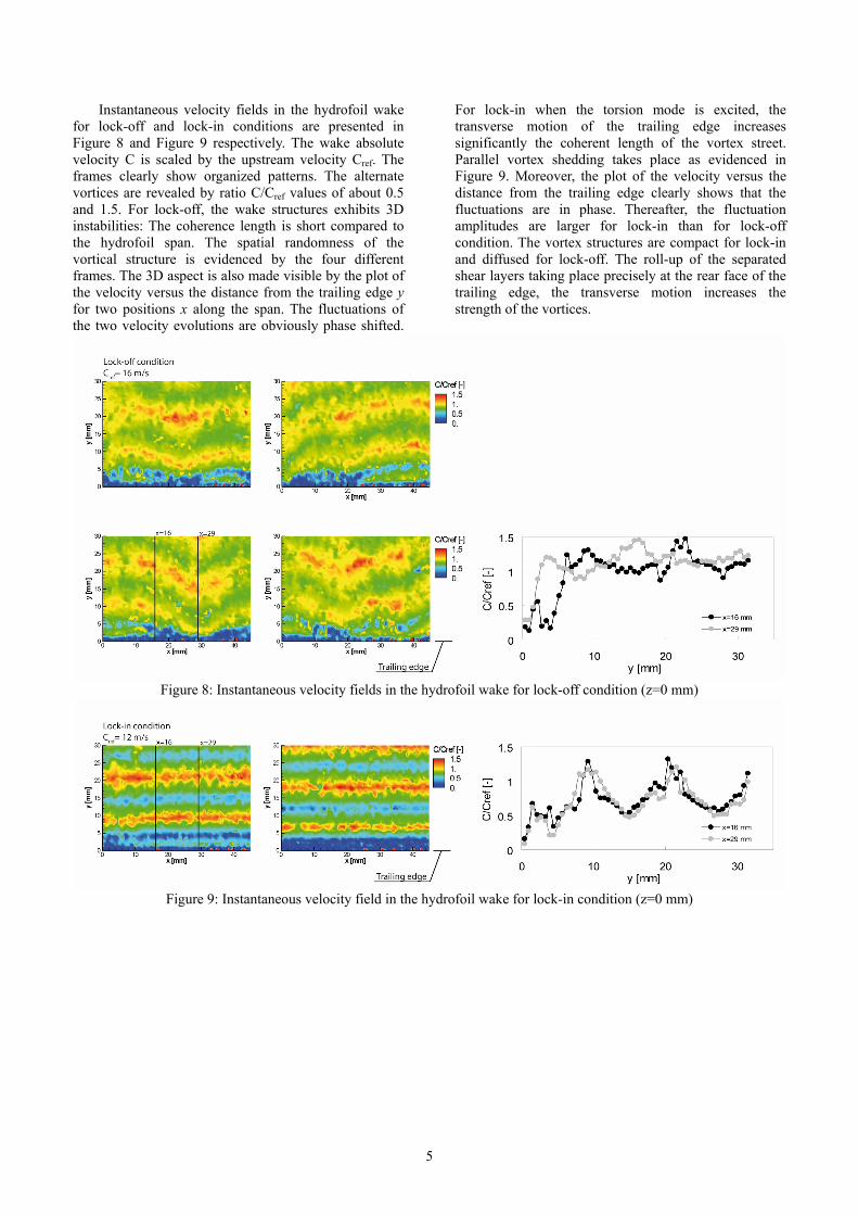
Instantaneous velocity fields in the hydrofoil wake for lock-off and lock-in conditions are presented in Figure 8 and Figure 9 respectively. The wake absolute velocity C is scaled by the upstream velocity Cref. The frames clearly show organized patterns. The alternate vortices are revealed by ratio C/Cref values of about 0.5 and 1.5. For lock-off, the wake structures exhibits 3D instabilities: The coherence length is short compared to the hydrofoil span. The spatial randomness of the vortical structure is evidenced by the four different frames. The 3D aspect is also made visible by the plot of the velocity versus the distance from the trailing edge y for two positions x along the span. The fluctuations of the two velocity evolutions are obviously phase shifted.
For lock-in when the torsion mode is excited, the transverse motion of the trailing edge increases significantly the coherent length of the vortex street. Parallel vortex shedding takes place as evidenced in Figure 9. Moreover, the plot of the velocity versus the distance from the trailing edge clearly shows that the fluctuations are in phase. Thereafter, the fluctuation amplitudes are larger for lock-in than for lock-off condition. The vortex structures are compact for lock-in and diffused for lock-off. The roll-up of the separated shear layers taking place precisely at the rear face of the trailing edge, the transverse motion increases the strength of the vortices.
Figure 8: Instantaneous velocity fields in the hydrofoil wake for lock-off condition (z=0 mm)
Figure 9: Instantaneous velocity field in the hydrofoil wake for lock-in condition (z=0 mm)
6
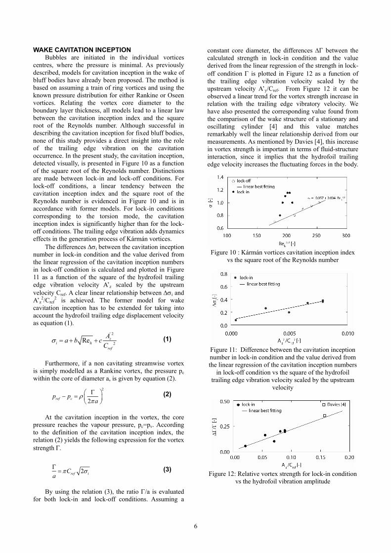
WAKE CAVITATION INCEPTION Bubbles are initiated in the individual vortices
centres, where the pressure is minimal. As previously described, models for cavitation inception in the wake of bluff bodies have already been proposed. The method is based on assuming a train of ring vortices and using the known pressure distribution for either Rankine or Oseen vortices. Relating the vortex core diameter to the boundary layer thickness, all models lead to a linear law between the cavitation inception index and the square root of the Reynolds number. Although successful in describing the cavitation inception for fixed bluff bodies, none of this study provides a direct insight into the role of the trailing edge vibration on the cavitation occurrence. In the present study, the cavitation inception, detected visually, is presented in Figure 10 as a function of the square root of the Reynolds number. Distinctions are made between lock-in and lock-off conditions. For lock-off conditions, a linear tendency between the cavitation inception index and the square root of the Reynolds number is evidenced in Figure 10 and is in accordance with former models. For lock-in conditions corresponding to the torsion mode, the cavitation inception index is significantly higher than for the lock-off conditions. The trailing edge vibration adds dynamics effects in the generation process of Kármán vortices.
The differences Δσi between the cavitation inception number in lock-in condition and the value derived from the linear regression of the cavitation inception numbers in lock-off condition is calculated and plotted in Figure 11 as a function of the square of the hydrofoil trailing edge vibration velocity A’z scaled by the upstream velocity Cref. A clear linear relationship between Δσi and A’z
2/Cref2 is achieved. The former model for wake
cavitation inception has to be extended for taking into account the hydrofoil trailing edge displacement velocity as equation (1).
' 2
2Re zi h
ref
Aa b cC
σ = + + (1)
Furthermore, if a non cavitating streamwise vortex is simply modelled as a Rankine vortex, the pressure pc within the core of diameter a, is given by equation (2).
2
2ref cp pa
ρπΓ⎛ ⎞− = ⎜ ⎟
⎝ ⎠ (2)
At the cavitation inception in the vortex, the core pressure reaches the vapour pressure, pc=pv. According to the definition of the cavitation inception index, the relation (2) yields the following expression for the vortex strength Γ.
2ref iCa
π σΓ= (3)
By using the relation (3), the ratio Γ/a is evaluated for both lock-in and lock-off conditions. Assuming a
constant core diameter, the differences ΔΓ between the calculated strength in lock-in condition and the value derived from the linear regression of the strength in lock-off condition Γ is plotted in Figure 12 as a function of the trailing edge vibration velocity scaled by the upstream velocity A’y/Cref. From Figure 12 it can be observed a linear trend for the vortex strength increase in relation with the trailing edge vibratory velocity. We have also presented the corresponding value found from the comparison of the wake structure of a stationary and oscillating cylinder [4] and this value matches remarkably well the linear relationship derived from our measurements. As mentioned by Davies [4], this increase in vortex strength is important in terms of fluid-structure interaction, since it implies that the hydrofoil trailing edge velocity increases the fluctuating forces in the body.
Figure 10 : Kármán vortices cavitation inception index
vs the square root of the Reynolds number
Figure 11: Difference between the cavitation inception number in lock-in condition and the value derived from the linear regression of the cavitation inception numbers
in lock-off condition vs the square of the hydrofoil trailing edge vibration velocity scaled by the upstream
velocity
Figure 12: Relative vortex strength for lock-in condition
vs the hydrofoil vibration amplitude
7
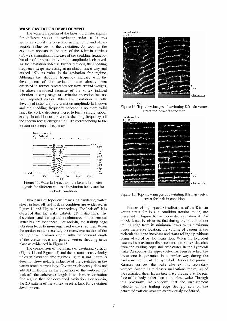
WAKE CAVITATION DEVELOPMENT The waterfall spectra of the laser vibrometer signals
for different values of cavitation index at 16 m/s upstream velocity is presented in Figure 13 and shows notable influences of the cavitation: As soon as the cavitation appears in the core of the Kármán vortices (σ/σi=1), a significant increase of the shedding frequency but also of the structural vibration amplitude is observed. As the cavitation index is further reduced, the shedding frequency keeps increasing in an almost linear way and exceed 15% its value in the cavitation free regime. Although the shedding frequency increase with the development of the cavitation have already been observed in former researches for flow around wedges, the above-mentioned increase of the vortex induced vibration at early stage of cavitation inception has not been reported earlier. When the cavitation is fully developed (σ/σi<0.4), the vibration amplitude falls down and the shedding frequency concept is no more valid since the vortex structures merge to form a single vapour cavity. In addition to the vortex shedding frequency, all the spectra reveal energy at 900 Hz corresponding to the torsion mode eigen frequency
Figure 13: Waterfall spectra of the laser vibrometer
signals for different values of cavitation index and for lock-off condition
Two pairs of top-view images of cavitating vortex
street in lock-off and lock-in condition are evidenced in Figure 14 and Figure 15 respectively. For lock-off, it is observed that the wake exhibits 3D instabilities. The distortions and the spatial randomness of the vortical structures are evidenced. For lock-in, the trailing edge vibration leads to more organized wake structures. When the torsion mode is excited, the transverse motion of the trailing edge increases significantly the coherent length of the vortex street and parallel vortex shedding takes place as evidenced in Figure 15.
The comparison of the images of cavitating vortices (Figure 14 and Figure 15) and the instantaneous velocity fields in cavitation free regime (Figure 8 and Figure 9) does not show notable influence of the cavitation in the vortex street morphology. Cavitation obviously does not add 3D instability in the advection of the vortices. For lock-off, the coherence length is as short in cavitation free regime than for developed cavitation. For lock-in, the 2D pattern of the vortex street is kept for cavitation development.
Figure 14: Top-view images of cavitating Kármán vortex
street for lock-off condition
Figure 15: Top-view images of cavitating Kármán vortex
street for lock-in condition
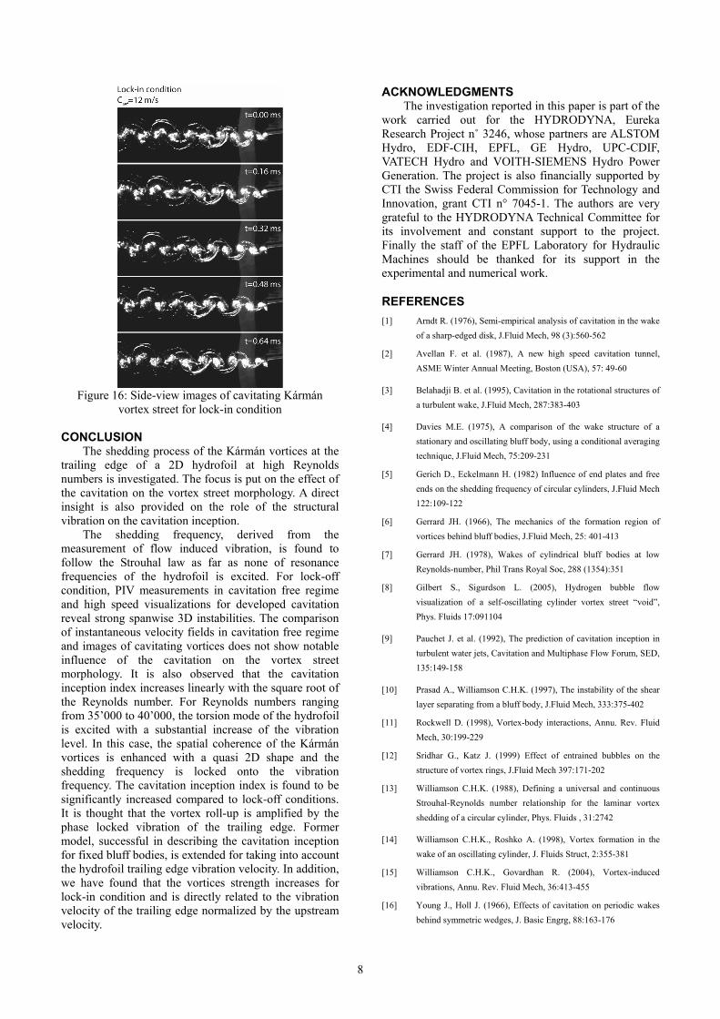
Frames of high speed visualisations of the Kármán vortex street for lock-in condition (torsion mode) are presented in Figure 16 for moderated cavitation at σ/σi =0.85. It can be observed that during the motion of the trailing edge from its minimum lower to its maximum upper transverse location, the volume of vapour in the recirculation zone increases and starts rolling-up without being advected by the mean flow. When the hydrofoil reaches its maximum displacement, the vortex detaches from the trailing edge and accelerates in the hydrofoil wake. As soon as the upper vortex has been detached, the lower one is generated in a similar way during the backward motion of the hydrofoil. Besides the primary Kármán vortices, the wake also exhibits secondary vortices. According to these visualisations, the roll-up of the separated shear layers take place precisely at the rear face of the body rather than in the close wake. Through this proximity, we conceive that the displacement velocity of the trailing edge strongly acts on the generated vortices strength as previously evidenced.
8
Figure 16: Side-view images of cavitating Kármán
vortex street for lock-in condition CONCLUSION
The shedding process of the Kármán vortices at the trailing edge of a 2D hydrofoil at high Reynolds numbers is investigated. The focus is put on the effect of the cavitation on the vortex street morphology. A direct insight is also provided on the role of the structural vibration on the cavitation inception.
The shedding frequency, derived from the measurement of flow induced vibration, is found to follow the Strouhal law as far as none of resonance frequencies of the hydrofoil is excited. For lock-off condition, PIV measurements in cavitation free regime and high speed visualizations for developed cavitation reveal strong spanwise 3D instabilities. The comparison of instantaneous velocity fields in cavitation free regime and images of cavitating vortices does not show notable influence of the cavitation on the vortex street morphology. It is also observed that the cavitation inception index increases linearly with the square root of the Reynolds number. For Reynolds numbers ranging from 35’000 to 40’000, the torsion mode of the hydrofoil is excited with a substantial increase of the vibration level. In this case, the spatial coherence of the Kármán vortices is enhanced with a quasi 2D shape and the shedding frequency is locked onto the vibration frequency. The cavitation inception index is found to be significantly increased compared to lock-off conditions. It is thought that the vortex roll-up is amplified by the phase locked vibration of the trailing edge. Former model, successful in describing the cavitation inception for fixed bluff bodies, is extended for taking into account the hydrofoil trailing edge vibration velocity. In addition, we have found that the vortices strength increases for lock-in condition and is directly related to the vibration velocity of the trailing edge normalized by the upstream velocity.
ACKNOWLEDGMENTS The investigation reported in this paper is part of the
work carried out for the HYDRODYNA, Eureka Research Project n˚ 3246, whose partners are ALSTOM Hydro, EDF-CIH, EPFL, GE Hydro, UPC-CDIF, VATECH Hydro and VOITH-SIEMENS Hydro Power Generation. The project is also financially supported by CTI the Swiss Federal Commission for Technology and Innovation, grant CTI n° 7045-1. The authors are very grateful to the HYDRODYNA Technical Committee for its involvement and constant support to the project. Finally the staff of the EPFL Laboratory for Hydraulic Machines should be thanked for its support in the experimental and numerical work.
REFERENCES [1] Arndt R. (1976), Semi-empirical analysis of cavitation in the wake
of a sharp-edged disk, J.Fluid Mech, 98 (3):560-562
[2] Avellan F. et al. (1987), A new high speed cavitation tunnel, ASME Winter Annual Meeting, Boston (USA), 57: 49-60
[3] Belahadji B. et al. (1995), Cavitation in the rotational structures of a turbulent wake, J.Fluid Mech, 287:383-403
[4] Davies M.E. (1975), A comparison of the wake structure of a stationary and oscillating bluff body, using a conditional averaging technique, J.Fluid Mech, 75:209-231
[5] Gerich D., Eckelmann H. (1982) Influence of end plates and free ends on the shedding frequency of circular cylinders, J.Fluid Mech 122:109-122
[6] Gerrard JH. (1966), The mechanics of the formation region of vortices behind bluff bodies, J.Fluid Mech, 25: 401-413
[7] Gerrard JH. (1978), Wakes of cylindrical bluff bodies at low Reynolds-number, Phil Trans Royal Soc, 288 (1354):351
[8] Gilbert S., Sigurdson L. (2005), Hydrogen bubble flow visualization of a self-oscillating cylinder vortex street “void”, Phys. Fluids 17:091104
[9] Pauchet J. et al. (1992), The prediction of cavitation inception in turbulent water jets, Cavitation and Multiphase Flow Forum, SED, 135:149-158
[10] Prasad A., Williamson C.H.K. (1997), The instability of the shear layer separating from a bluff body, J.Fluid Mech, 333:375-402
[11] Rockwell D. (1998), Vortex-body interactions, Annu. Rev. Fluid Mech, 30:199-229
[12] Sridhar G., Katz J. (1999) Effect of entrained bubbles on the structure of vortex rings, J.Fluid Mech 397:171-202
[13] Williamson C.H.K. (1988), Defining a universal and continuous Strouhal-Reynolds number relationship for the laminar vortex shedding of a circular cylinder, Phys. Fluids , 31:2742
[14] Williamson C.H.K., Roshko A. (1998), Vortex formation in the wake of an oscillating cylinder, J. Fluids Struct, 2:355-381
[15] Williamson C.H.K., Govardhan R. (2004), Vortex-induced vibrations, Annu. Rev. Fluid Mech, 36:413-455
[16] Young J., Holl J. (1966), Effects of cavitation on periodic wakes behind symmetric wedges, J. Basic Engrg, 88:163-176


![arXiv:1203.5133v1 [cond-mat.other] 22 Mar 2012sive vortex-vortex interaction, and sound waves emitted by moving and repinning vortices. So long as dissipation is low, sound waves emitted](https://img.dokumen.tips/doc/110x75/5e8ab2d539fa834d757bf1bf/arxiv12035133v1-cond-matother-22-mar-2012-sive-vortex-vortex-interaction-and.jpg)


![Quantized vortex stability and interaction in the ......vortices. The seminal work of Abrikosov [2] in 1957 already made predictions of the vortex lattice in superconductors a decade](https://img.dokumen.tips/doc/110x75/60c2886922cecb55e8539886/quantized-vortex-stability-and-interaction-in-the-vortices-the-seminal.jpg)