Embed Size (px)
Citation preview

Catalyst 2950 Desktop Switch Software Configuration GuideCisco IOS Release 12.1(11)EA1August 2002
Corporate HeadquartersCisco Systems, Inc.170 West Tasman DriveSan Jose, CA 95134-1706 USAhttp://www.cisco.comTel: 408 526-4000
800 553-NETS (6387)Fax: 408 526-4100
Customer Order Number: DOC-7811380=Text Part Number: 78-11380-05

THE SPECIFICATIONS AND INFORMATION REGARDING THE PRODUCTS IN THIS MANUAL ARE SUBJECT TO CHANGE WITHOUT NOTICE. ALL STATEMENTS, INFORMATION, AND RECOMMENDATIONS IN THIS MANUAL ARE BELIEVED TO BE ACCURATE BUT ARE PRESENTED WITHOUT WARRANTY OF ANY KIND, EXPRESS OR IMPLIED. USERS MUST TAKE FULL RESPONSIBILITY FOR THEIR APPLICATION OF ANY PRODUCTS.
THE SOFTWARE LICENSE AND LIMITED WARRANTY FOR THE ACCOMPANYING PRODUCT ARE SET FORTH IN THE INFORMATION PACKET THAT SHIPPED WITH THE PRODUCT AND ARE INCORPORATED HEREIN BY THIS REFERENCE. IF YOU ARE UNABLE TO LOCATE THE SOFTWARE LICENSE OR LIMITED WARRANTY, CONTACT YOUR CISCO REPRESENTATIVE FOR A COPY.
The Cisco implementation of TCP header compression is an adaptation of a program developed by the University of California, Berkeley (UCB) as part of UCB’s public domain version of the UNIX operating system. All rights reserved. Copyright © 1981, Regents of the University of California.
NOTWITHSTANDING ANY OTHER WARRANTY HEREIN, ALL DOCUMENT FILES AND SOFTWARE OF THESE SUPPLIERS ARE PROVIDED “AS IS” WITH ALL FAULTS. CISCO AND THE ABOVE-NAMED SUPPLIERS DISCLAIM ALL WARRANTIES, EXPRESSED OR IMPLIED, INCLUDING, WITHOUT LIMITATION, THOSE OF MERCHANTABILITY, FITNESS FOR A PARTICULAR PURPOSE AND NONINFRINGEMENT OR ARISING FROM A COURSE OF DEALING, USAGE, OR TRADE PRACTICE.
IN NO EVENT SHALL CISCO OR ITS SUPPLIERS BE LIABLE FOR ANY INDIRECT, SPECIAL, CONSEQUENTIAL, OR INCIDENTAL DAMAGES, INCLUDING, WITHOUT LIMITATION, LOST PROFITS OR LOSS OR DAMAGE TO DATA ARISING OUT OF THE USE OR INABILITY TO USE THIS MANUAL, EVEN IF CISCO OR ITS SUPPLIERS HAVE BEEN ADVISED OF THE POSSIBILITY OF SUCH DAMAGES.
Catalyst 2950 Desktop Switch Software Configuration GuideCopyright © 2001-2002, Cisco Systems, Inc.All rights reserved.
CCIP, the Cisco Arrow logo, the Cisco Powered Network mark, the Cisco Systems Verified logo, Cisco Unity, Follow Me Browsing, FormShare, Internet Quotient, iQ Breakthrough, iQ Expertise, iQ FastTrack, the iQ Logo, iQ Net Readiness Scorecard, Networking Academy, ScriptShare, SMARTnet, TransPath, and Voice LAN are trademarks of Cisco Systems, Inc.; Changing the Way We Work, Live, Play, and Learn, Discover All That’s Possible, The Fastest Way to Increase Your Internet Quotient, and iQuick Study are service marks of Cisco Systems, Inc.; and Aironet, ASIST, BPX, Catalyst, CCDA, CCDP, CCIE, CCNA, CCNP, Cisco, the Cisco Certified Internetwork Expert logo, Cisco IOS, the Cisco IOS logo, Cisco Press, Cisco Systems, Cisco Systems Capital, the Cisco Systems logo, Empowering the Internet Generation, Enterprise/Solver, EtherChannel, EtherSwitch, Fast Step, GigaStack, IOS, IP/TV, LightStream, MGX, MICA, the Networkers logo, Network Registrar, Packet, PIX, Post-Routing, Pre-Routing, RateMUX, Registrar, SlideCast, StrataView Plus, Stratm, SwitchProbe, TeleRouter, and VCO are registered trademarks of Cisco Systems, Inc. and/or its affiliates in the U.S. and certain other countries.
All other trademarks mentioned in this document or Web site are the property of their respective owners. The use of the word partner does not imply a partnership relationship between Cisco and any other company. (0206R)
Catal78-11380-05
C O N T E N T S
Preface xxiii
Audience xxiii
Purpose xxiii
Organization xxiv
Conventions xxvi
Related Publications xxvii
Obtaining Documentation xxvii
World Wide Web xxvii
Documentation CD-ROM xxviii
Ordering Documentation xxviii
Documentation Feedback xxviii
Obtaining Technical Assistance xxviii
Cisco.com xxix
Technical Assistance Center xxix
Cisco TAC Website xxix
Cisco TAC Escalation Center xxx
C H A P T E R 1 Overview 1-1
Features 1-1
Management Options 1-5
Management Interface Options 1-6
Advantages of Using CMS and Clustering Switches 1-6
Network Configuration Examples 1-7
Design Concepts for Using the Switch 1-7
Small to Medium-Sized Network Configuration 1-10
Collapsed Backbone and Switch Cluster Configuration 1-12
Large Campus Configuration 1-13
Multidwelling Network Using Catalyst 2950 Switches 1-14
Long-Distance, High-Bandwidth Transport Configuration 1-16
Where to Go Next 1-17
iiiyst 2950 Desktop Switch Software Configuration Guide

Contents
C H A P T E R 2 Using the Command-Line Interface 2-1
IOS Command Modes 2-1
Getting Help 2-3
Abbreviating Commands 2-3
Using no and default Forms of Commands 2-4
Understanding CLI Messages 2-4
Using Command History 2-5
Changing the Command History Buffer Size 2-5
Recalling Commands 2-5
Disabling the Command History Feature 2-6
Using Editing Features 2-6
Enabling and Disabling Editing Features 2-6
Editing Commands through Keystrokes 2-7
Editing Command Lines that Wrap 2-8
Searching and Filtering Output of show and more Commands 2-9
Accessing the CLI 2-9
Accessing the CLI from a Browser 2-10
C H A P T E R 3 Getting Started with CMS 3-1
Features 3-2
Front Panel View 3-4
Cluster Tree 3-5
Front-Panel Images 3-5
Redundant Power System LED 3-6
Port Modes and LEDs 3-7
VLAN Membership Modes 3-8
Topology View 3-9
Topology Icons 3-11
Device and Link Labels 3-12
Colors in the Topology View 3-12
Topology Display Options 3-13
Menus and Toolbar 3-14
Menu Bar 3-14
Toolbar 3-19
Front Panel View Popup Menus 3-20
Device Popup Menu 3-20
Port Popup Menu 3-20
ivCatalyst 2950 Desktop Switch Software Configuration Guide
78-11380-05

Contents
Topology View Popup Menus 3-21
Link Popup Menu 3-21
Device Popup Menus 3-22
Interaction Modes 3-23
Guide Mode 3-24
Expert Mode 3-24
Wizards 3-24
Tool Tips 3-25
Online Help 3-25
CMS Window Components 3-26
Host Name List 3-26
Tabs, Lists, and Tables 3-27
Icons Used in Windows 3-27
Buttons 3-27
Accessing CMS 3-28
Access Modes in CMS 3-29
HTTP Access to CMS 3-29
Verifying Your Changes 3-30
Change Notification 3-30
Error Checking 3-30
Saving Your Configuration 3-30
Restoring Your Configuration 3-31
CMS Preferences 3-31
Using Different Versions of CMS 3-31
Where to Go Next 3-32
C H A P T E R 4 Assigning the Switch IP Address and Default Gateway 4-1
Understanding the Boot Process 4-1
Assigning Switch Information 4-2
Default Switch Information 4-3
Understanding DHCP-Based Autoconfiguration 4-3
DHCP Client Request Process 4-4
Configuring the DHCP Server 4-5
Configuring the TFTP Server 4-5
Configuring the DNS 4-6
Configuring the Relay Device 4-6
Obtaining Configuration Files 4-7
Example Configuration 4-8
vCatalyst 2950 Desktop Switch Software Configuration Guide
78-11380-05

Contents
Manually Assigning IP Information 4-10
Checking and Saving the Running Configuration 4-10
C H A P T E R 5 Configuring IE2100 CNS Agents 5-1
Understanding IE2100 Series Configuration Registrar Software 5-1
CNS Configuration Service 5-2
CNS Event Service 5-3
NameSpace Mapper 5-3
What You Should Know About ConfigID, DeviceID, and Host Name 5-3
ConfigID 5-3
DeviceID 5-4
Host Name and DeviceID 5-4
Using Host Name, DeviceID, and ConfigID 5-4
Understanding CNS Embedded Agents 5-5
Initial Configuration 5-5
Incremental (Partial) Configuration 5-6
Synchronized Configuration 5-6
Configuring CNS Embedded Agents 5-6
Enabling Automated CNS Configuration 5-6
Enabling the CNS Event Agent 5-8
Enabling the CNS Configuration Agent 5-9
Enabling an Initial Configuration 5-9
Enabling a Partial Configuration 5-12
Displaying CNS Configuration 5-12
C H A P T E R 6 Clustering Switches 6-1
Understanding Switch Clusters 6-2
Command Switch Characteristics 6-3
Standby Command Switch Characteristics 6-3
Candidate Switch and Member Switch Characteristics 6-4
Planning a Switch Cluster 6-5
Automatic Discovery of Cluster Candidates and Members 6-5
Discovery through CDP Hops 6-6
Discovery through Non-CDP-Capable and Noncluster-Capable Devices 6-8
Discovery through the Same Management VLAN 6-9
Discovery through Different Management VLANs 6-10
Discovery of Newly Installed Switches 6-11
viCatalyst 2950 Desktop Switch Software Configuration Guide
78-11380-05

Contents
HSRP and Standby Command Switches 6-13
Virtual IP Addresses 6-14
Other Considerations for Cluster Standby Groups 6-14
Automatic Recovery of Cluster Configuration 6-16
IP Addresses 6-16
Host Names 6-17
Passwords 6-17
SNMP Community Strings 6-17
TACACS+ and RADIUS 6-18
Access Modes in CMS 6-18
Management VLAN 6-19
LRE Profiles 6-19
Availability of Switch-Specific Features in Switch Clusters 6-20
Creating a Switch Cluster 6-20
Enabling a Command Switch 6-20
Adding Member Switches 6-21
Creating a Cluster Standby Group 6-23
Verifying a Switch Cluster 6-25
Using the CLI to Manage Switch Clusters 6-26
Catalyst 1900 and Catalyst 2820 CLI Considerations 6-26
Using SNMP to Manage Switch Clusters 6-27
C H A P T E R 7 Administering the Switch 7-1
Preventing Unauthorized Access to Your Switch 7-1
Protecting Access to Privileged EXEC Commands 7-2
Default Password and Privilege Level Configuration 7-2
Setting or Changing a Static Enable Password 7-3
Protecting Enable and Enable Secret Passwords with Encryption 7-4
Setting a Telnet Password for a Terminal Line 7-5
Configuring Username and Password Pairs 7-6
Configuring Multiple Privilege Levels 7-7
Setting the Privilege Level for a Command 7-7
Changing the Default Privilege Level for Lines 7-8
Logging into and Exiting a Privilege Level 7-9
Controlling Switch Access with TACACS+ 7-9
Understanding TACACS+ 7-9
TACACS+ Operation 7-11
viiCatalyst 2950 Desktop Switch Software Configuration Guide
78-11380-05

Contents
Configuring TACACS+ 7-11
Default TACACS+ Configuration 7-12
Identifying the TACACS+ Server Host and Setting the Authentication Key 7-12
Configuring TACACS+ Login Authentication 7-13
Configuring TACACS+ Authorization for Privileged EXEC Access and Network Services 7-15
Starting TACACS+ Accounting 7-16
Displaying the TACACS+ Configuration 7-16
Controlling Switch Access with RADIUS 7-17
Understanding RADIUS 7-17
RADIUS Operation 7-18
Configuring RADIUS 7-19
Default RADIUS Configuration 7-19
Identifying the RADIUS Server Host 7-19
Configuring RADIUS Login Authentication 7-22
Defining AAA Server Groups 7-24
Configuring RADIUS Authorization for User Privileged Access and Network Services 7-26
Starting RADIUS Accounting 7-27
Configuring Settings for All RADIUS Servers 7-28
Configuring the Switch to Use Vendor-Specific RADIUS Attributes 7-28
Configuring the Switch for Vendor-Proprietary RADIUS Server Communication 7-29
Displaying the RADIUS Configuration 7-30
Configuring the Switch for Local Authentication and Authorization 7-31
Managing the System Time and Date 7-32
Understanding the System Clock 7-32
Understanding Network Time Protocol 7-32
Configuring NTP 7-34
Default NTP Configuration 7-35
Configuring NTP Authentication 7-35
Configuring NTP Associations 7-36
Configuring NTP Broadcast Service 7-37
Configuring NTP Access Restrictions 7-38
Configuring the Source IP Address for NTP Packets 7-40
Displaying the NTP Configuration 7-41
Configuring Time and Date Manually 7-41
Setting the System Clock 7-42
Displaying the Time and Date Configuration 7-42
Configuring the Time Zone 7-43
Configuring Summer Time (Daylight Saving Time) 7-44
viiiCatalyst 2950 Desktop Switch Software Configuration Guide
78-11380-05
Contents
Configuring a System Name and Prompt 7-46
Default System Name and Prompt Configuration 7-46
Configuring a System Name 7-46
Configuring a System Prompt 7-47
Understanding DNS 7-47
Default DNS Configuration 7-48
Setting Up DNS 7-48
Displaying the DNS Configuration 7-49
Creating a Banner 7-49
Default Banner Configuration 7-49
Configuring a Message-of-the-Day Login Banner 7-50
Configuring a Login Banner 7-51
Managing the MAC Address Table 7-52
Building the Address Table 7-52
MAC Addresses and VLANs 7-53
Default MAC Address Table Configuration 7-53
Changing the Address Aging Time 7-53
Removing Dynamic Address Entries 7-54
Configuring MAC Address Notification Traps 7-54
Adding and Removing Static Address Entries 7-56
Adding and Removing Secure Addresses 7-57
Displaying Address Table Entries 7-58
Managing the ARP Table 7-59
C H A P T E R 8 Configuring 802.1X Port-Based Authentication 8-1
Understanding 802.1X Port-Based Authentication 8-1
Device Roles 8-2
Authentication Initiation and Message Exchange 8-3
Ports in Authorized and Unauthorized States 8-4
Supported Topologies 8-5
Configuring 802.1X Authentication 8-5
Default 802.1X Configuration 8-6
802.1X Configuration Guidelines 8-7
Enabling 802.1X Authentication 8-8
Configuring the Switch-to-RADIUS-Server Communication 8-9
Enabling Periodic Re-Authentication 8-10
Manually Re-Authenticating a Client Connected to a Port 8-11
Changing the Quiet Period 8-11
Changing the Switch-to-Client Retransmission Time 8-12
ixCatalyst 2950 Desktop Switch Software Configuration Guide
78-11380-05

Contents
Setting the Switch-to-Client Frame-Retransmission Number 8-13
Enabling Multiple Hosts 8-13
Resetting the 802.1X Configuration to the Default Values 8-14
Displaying 802.1X Statistics and Status 8-14
C H A P T E R 9 Configuring Interface Characteristics 9-1
Understanding Interface Types 9-1
Port-Based VLANs 9-1
Switch Ports 9-2
Access Ports 9-2
Trunk Ports 9-3
EtherChannel Port Groups 9-3
Connecting Interfaces 9-3
Using the Interface Command 9-4
Procedures for Configuring Interfaces 9-5
Configuring a Range of Interfaces 9-6
Configuring and Using Interface Range Macros 9-8
Configuring Layer 2 Interfaces 9-9
Default Layer 2 Ethernet Interface Configuration 9-9
Configuring Interface Speed and Duplex Mode 9-10
Configuration Guidelines 9-11
Setting the Interface Speed and Duplex Parameters 9-11
Configuring IEEE 802.3X Flow Control on Gigabit Ethernet Ports 9-12
Adding a Description for an Interface 9-13
Monitoring and Maintaining the Interfaces 9-14
Monitoring Interface and Controller Status 9-14
Clearing and Resetting Interfaces and Counters 9-16
Shutting Down and Restarting the Interface 9-17
C H A P T E R 10 Configuring STP 10-1
Understanding Spanning-Tree Features 10-1
STP Overview 10-2
Supported Spanning-Tree Instances 10-2
Bridge Protocol Data Units 10-2
Election of the Root Switch 10-3
Bridge ID, Switch Priority, and Extended System ID 10-4
Spanning-Tree Timers 10-4
Creating the Spanning-Tree Topology 10-5
xCatalyst 2950 Desktop Switch Software Configuration Guide
78-11380-05

Contents
Spanning-Tree Interface States 10-5
Blocking State 10-7
Listening State 10-7
Learning State 10-7
Forwarding State 10-7
Disabled State 10-8
Spanning-Tree Address Management 10-8
STP and IEEE 802.1Q Trunks 10-8
Spanning Tree and Redundant Connectivity 10-8
Accelerated Aging to Retain Connectivity 10-9
Configuring Spanning-Tree Features 10-9
Default STP Configuration 10-10
STP Configuration Guidelines 10-10
Disabling STP 10-12
Configuring the Root Switch 10-12
Configuring a Secondary Root Switch 10-14
Configuring the Port Priority 10-15
Configuring the Path Cost 10-16
Configuring the Switch Priority of a VLAN 10-18
Configuring the Hello Time 10-19
Configuring the Forwarding-Delay Time for a VLAN 10-19
Configuring the Maximum-Aging Time for a VLAN 10-20
Configuring STP for Use in a Cascaded Stack 10-20
Displaying the Spanning-Tree Status 10-21
C H A P T E R 11 Configuring RSTP and MSTP 11-1
Understanding RSTP 11-2
Port Roles and the Active Topology 11-2
Rapid Convergence 11-3
Synchronization of Port Roles 11-4
Bridge Protocol Data Unit Format and Processing 11-5
Processing Superior BPDU Information 11-6
Processing Inferior BPDU Information 11-6
Topology Changes 11-6
Understanding MSTP 11-7
Multiple Spanning-Tree Regions 11-7
IST, CIST, and CST 11-8
Operations Within an MST Region 11-8
Operations Between MST Regions 11-9
xiCatalyst 2950 Desktop Switch Software Configuration Guide
78-11380-05

Contents
Hop Count 11-10
Boundary Ports 11-10
Interoperability with 802.1D STP 11-11
Configuring RSTP and MSTP Features 11-11
Default RSTP and MSTP Configuration 11-12
RSTP and MSTP Configuration Guidelines 11-12
Specifying the MST Region Configuration and Enabling MSTP 11-13
Configuring the Root Switch 11-14
Configuring a Secondary Root Switch 11-16
Configuring the Port Priority 11-17
Configuring the Path Cost 11-18
Configuring the Switch Priority 11-19
Configuring the Hello Time 11-19
Configuring the Forwarding-Delay Time 11-20
Configuring the Maximum-Aging Time 11-21
Configuring the Maximum-Hop Count 11-21
Specifying the Link Type to Ensure Rapid Transitions 11-22
Restarting the Protocol Migration Process 11-22
Displaying the MST Configuration and Status 11-23
C H A P T E R 12 Configuring Optional Spanning-Tree Features 12-1
Understanding Optional Spanning-Tree Features 12-1
Understanding Port Fast 12-2
Understanding BPDU Guard 12-3
Understanding BPDU Filtering 12-3
Understanding UplinkFast 12-4
Understanding Cross-Stack UplinkFast 12-5
How CSUF Works 12-6
Events That Cause Fast Convergence 12-7
Limitations 12-8
Connecting the Stack Ports 12-8
Understanding BackboneFast 12-10
Understanding Root Guard 12-12
Understanding Loop Guard 12-13
Configuring Optional Spanning-Tree Features 12-13
Default Optional Spanning-Tree Configuration 12-14
Enabling Port Fast 12-14
Enabling BPDU Guard 12-15
Enabling BPDU Filtering 12-16
xiiCatalyst 2950 Desktop Switch Software Configuration Guide
78-11380-05

Contents
Enabling UplinkFast for Use with Redundant Links 12-17
Enabling Cross-Stack UplinkFast 12-18
Enabling BackboneFast 12-19
Enabling Root Guard 12-19
Enabling Loop Guard 12-20
Displaying the Spanning-Tree Status 12-21
C H A P T E R 13 Configuring VLANs 13-1
Understanding VLANs 13-1
Supported VLANs 13-2
VLAN Port Membership Modes 13-3
Configuring Normal-Range VLANs 13-4
Token Ring VLANs 13-5
Normal-Range VLAN Configuration Guidelines 13-5
VLAN Configuration Mode Options 13-6
VLAN Configuration in config-vlan Mode 13-6
VLAN Configuration in VLAN Configuration Mode 13-6
Saving VLAN Configuration 13-7
Default Ethernet VLAN Configuration 13-8
Creating or Modifying an Ethernet VLAN 13-8
Deleting a VLAN 13-10
Assigning Static-Access Ports to a VLAN 13-11
Configuring Extended-Range VLANs 13-12
Default VLAN Configuration 13-12
Extended-Range VLAN Configuration Guidelines 13-12
Creating an Extended-Range VLAN 13-13
Displaying VLANs 13-14
Configuring VLAN Trunks 13-15
Trunking Overview 13-15
802.1Q Configuration Considerations 13-16
Default Layer 2 Ethernet Interface VLAN Configuration 13-17
Configuring an Ethernet Interface as a Trunk Port 13-17
Interaction with Other Features 13-17
Configuring a Trunk Port 13-18
Defining the Allowed VLANs on a Trunk 13-19
Changing the Pruning-Eligible List 13-20
Configuring the Native VLAN for Untagged Traffic 13-20
xiiiCatalyst 2950 Desktop Switch Software Configuration Guide
78-11380-05

Contents
Load Sharing Using STP 13-21
Load Sharing Using STP Port Priorities 13-21
Load Sharing Using STP Path Cost 13-23
Configuring VMPS 13-24
Understanding VMPS 13-25
Dynamic Port VLAN Membership 13-25
VMPS Database Configuration File 13-26
Default VMPS Configuration 13-27
VMPS Configuration Guidelines 13-28
Configuring the VMPS Client 13-28
Entering the IP Address of the VMPS 13-28
Configuring Dynamic Access Ports on VMPS Clients 13-29
Reconfirming VLAN Memberships 13-30
Changing the Reconfirmation Interval 13-30
Changing the Retry Count 13-30
Monitoring the VMPS 13-31
Troubleshooting Dynamic Port VLAN Membership 13-31
VMPS Configuration Example 13-32
C H A P T E R 14 Configuring VTP 14-1
Understanding VTP 14-1
The VTP Domain 14-2
VTP Modes 14-3
VTP Advertisements 14-3
VTP Version 2 14-4
VTP Pruning 14-4
Configuring VTP 14-6
Default VTP Configuration 14-6
VTP Configuration Options 14-7
VTP Configuration in Global Configuration Modes 14-7
VTP Configuration in VLAN Configuration Mode 14-7
VTP Configuration Guidelines 14-8
Domain Names 14-8
Passwords 14-8
Upgrading from Previous Software Releases 14-8
VTP Version 14-9
Configuration Requirements 14-9
Configuring a VTP Server 14-9
Configuring a VTP Client 14-11
xivCatalyst 2950 Desktop Switch Software Configuration Guide
78-11380-05

Contents
Disabling VTP (VTP Transparent Mode) 14-12
Enabling VTP Version 2 14-13
Enabling VTP Pruning 14-14
Adding a VTP Client Switch to a VTP Domain 14-15
Monitoring VTP 14-16
C H A P T E R 15 Configuring Voice VLAN 15-1
Understanding Voice VLAN 15-1
Configuring Voice VLAN 15-2
Default Voice VLAN Configuration 15-2
Voice VLAN Configuration Guidelines 15-3
Configuring a Port to Connect to a Cisco 7960 IP Phone 15-3
Configuring Ports to Carry Voice Traffic in 802.1Q Frames 15-4
Configuring Ports to Carry Voice Traffic in 802.1P Priority Tagged Frames 15-4
Overriding the CoS Priority of Incoming Data Frames 15-5
Configuring the IP Phone to Trust the CoS Priority of Incoming Data Frames 15-6
Displaying Voice VLAN 15-6
C H A P T E R 16 Configuring IGMP Snooping and MVR 16-1
Understanding IGMP Snooping 16-1
Joining a Multicast Group 16-2
Leaving a Multicast Group 16-4
Immediate-Leave Processing 16-4
Configuring IGMP Snooping 16-5
Default IGMP Snooping Configuration 16-5
Enabling or Disabling IGMP Snooping 16-5
Setting the Snooping Method 16-6
Configuring a Multicast Router Port 16-7
Configuring a Host Statically to Join a Group 16-8
Enabling IGMP Immediate-Leave Processing 16-9
Displaying IGMP Snooping Information 16-9
Understanding Multicast VLAN Registration 16-12
Using MVR in a Multicast Television Application 16-12
Configuring MVR 16-14
Default MVR Configuration 16-14
MVR Configuration Guidelines and Limitations 16-15
Configuring MVR Global Parameters 16-15
Configuring MVR Interfaces 16-16
xvCatalyst 2950 Desktop Switch Software Configuration Guide
78-11380-05

Contents
Displaying MVR Information 16-18
Configuring IGMP Filtering 16-19
Default IGMP Filtering Configuration 16-19
Configuring IGMP Profiles 16-20
Applying IGMP Profiles 16-21
Setting the Maximum Number of IGMP Groups 16-22
Displaying IGMP Filtering Configuration 16-23
C H A P T E R 17 Configuring Port-Based Traffic Control 17-1
Configuring Storm Control 17-1
Understanding Storm Control 17-1
Default Storm Control Configuration 17-2
Enabling Storm Control 17-2
Disabling Storm Control 17-3
Configuring Protected Ports 17-3
Configuring Port Security 17-4
Understanding Port Security 17-4
Secure MAC Addresses 17-5
Security Violations 17-6
Default Port Security Configuration 17-6
Port Security Configuration Guidelines 17-7
Enabling and Configuring Port Security 17-7
Enabling and Configuring Port Security Aging 17-10
Displaying Port-Based Traffic Control Settings 17-12
C H A P T E R 18 Configuring UDLD 18-1
Understanding UDLD 18-1
Configuring UDLD 18-3
Default UDLD Configuration 18-3
Enabling UDLD Globally 18-4
Enabling UDLD on an Interface 18-4
Resetting an Interface Shut Down by UDLD 18-5
Displaying UDLD Status 18-6
xviCatalyst 2950 Desktop Switch Software Configuration Guide
78-11380-05

Contents
C H A P T E R 19 Configuring CDP 19-1
Understanding CDP 19-1
Configuring CDP 19-2
Default CDP Configuration 19-2
Configuring the CDP Characteristics 19-2
Disabling and Enabling CDP 19-3
Disabling and Enabling CDP on an Interface 19-4
Monitoring and Maintaining CDP 19-5
C H A P T E R 20 Configuring SPAN and RSPAN 20-1
Understanding SPAN and RSPAN 20-1
SPAN and RSPAN Concepts and Terminology 20-3
SPAN Session 20-3
Traffic Types 20-3
Source Port 20-4
Destination Port 20-4
Reflector Port 20-4
SPAN Traffic 20-5
SPAN and RSPAN Interaction with Other Features 20-5
SPAN and RSPAN Session Limits 20-6
Default SPAN and RSPAN Configuration 20-6
Configuring SPAN 20-7
SPAN Configuration Guidelines 20-7
Creating a SPAN Session and Specifying Ports to Monitor 20-7
Removing Ports from a SPAN Session 20-9
Configuring RSPAN 20-10
RSPAN Configuration Guidelines 20-10
Creating an RSPAN Session 20-11
Creating an RSPAN Destination Session 20-12
Removing Ports from an RSPAN Session 20-13
Displaying SPAN and RSPAN Status 20-14
xviiCatalyst 2950 Desktop Switch Software Configuration Guide
78-11380-05

Contents
C H A P T E R 21 Configuring RMON 21-1
Understanding RMON 21-1
Configuring RMON 21-2
Default RMON Configuration 21-3
Configuring RMON Alarms and Events 21-3
Configuring RMON Collection on an Interface 21-5
Displaying RMON Status 21-6
C H A P T E R 22 Configuring System Message Logging 22-1
Understanding System Message Logging 22-1
Configuring System Message Logging 22-2
System Log Message Format 22-2
Default System Message Logging Configuration 22-3
Disabling and Enabling Message Logging 22-4
Setting the Message Display Destination Device 22-4
Synchronizing Log Messages 22-6
Enabling and Disabling Timestamps on Log Messages 22-7
Enabling and Disabling Sequence Numbers in Log Messages 22-8
Defining the Message Severity Level 22-8
Limiting Syslog Messages Sent to the History Table and to SNMP 22-10
Configuring UNIX Syslog Servers 22-10
Logging Messages to a UNIX Syslog Daemon 22-11
Configuring the UNIX System Logging Facility 22-11
Displaying the Logging Configuration 22-12
C H A P T E R 23 Configuring SNMP 23-1
Understanding SNMP 23-1
SNMP Versions 23-2
SNMP Manager Functions 23-3
SNMP Agent Functions 23-3
SNMP Community Strings 23-4
Using SNMP to Access MIB Variables 23-4
SNMP Notifications 23-5
Configuring SNMP 23-5
Default SNMP Configuration 23-6
SNMP Configuration Guidelines 23-6
Disabling the SNMP Agent 23-7
Configuring Community Strings 23-7
xviiiCatalyst 2950 Desktop Switch Software Configuration Guide
78-11380-05

Contents
Configuring SNMP Groups and Users 23-8
Configuring SNMP Notifications 23-10
Setting the Agent Contact and Location Information 23-13
Limiting TFTP Servers Used Through SNMP 23-13
SNMP Examples 23-14
Displaying SNMP Status 23-15
C H A P T E R 24 Configuring Network Security with ACLs 24-1
Understanding ACLs 24-2
Handling Fragmented and Unfragmented Traffic 24-3
Understanding Access Control Parameters 24-4
Guidelines for Applying ACLs to Physical Interfaces 24-6
Configuring ACLs 24-6
Unsupported Features 24-7
Creating Standard and Extended IP ACLs 24-7
ACL Numbers 24-8
Creating a Numbered Standard ACL 24-9
Creating a Numbered Extended ACL 24-10
Creating Named Standard and Extended ACLs 24-13
Applying Time Ranges to ACLs 24-15
Including Comments About Entries in ACLs 24-17
Creating Named MAC Extended ACLs 24-18
Creating MAC Access Groups 24-19
Applying ACLs to Terminal Lines or Physical Interfaces 24-20
Applying ACLs to a Terminal Line 24-20
Applying ACLs to a Physical Interface 24-21
Displaying ACL Information 24-21
Displaying ACLs 24-22
Displaying Access Groups 24-23
Examples for Compiling ACLs 24-23
Numbered ACL Examples 24-25
Extended ACL Examples 24-25
Named ACL Example 24-25
Commented IP ACL Entry Examples 24-25
xixCatalyst 2950 Desktop Switch Software Configuration Guide
78-11380-05

Contents
C H A P T E R 25 Configuring QoS 25-1
Understanding QoS 25-2
Basic QoS Model 25-3
Classification 25-4
Classification Based on QoS ACLs 25-5
Classification Based on Class Maps and Policy Maps 25-6
Policing and Marking 25-6
Mapping Tables 25-7
Queueing and Scheduling 25-7
How Class of Service Works 25-7
Port Priority 25-8
Port Scheduling 25-8
CoS and WRR 25-8
Configuring QoS 25-9
Default QoS Configuration 25-9
Configuration Guidelines 25-10
Configuring Classification Using Port Trust States 25-10
Configuring the Trust State on Ports within the QoS Domain 25-11
Configuring the CoS Value for an Interface 25-13
Configuring Trusted Boundary 25-13
Enabling Pass-Through Mode 25-15
Configuring a QoS Policy 25-16
Classifying Traffic by Using ACLs 25-16
Classifying Traffic by Using Class Maps 25-20
Classifying, Policing, and Marking Traffic by Using Policy Maps 25-21
Configuring CoS Maps 25-24
Configuring the CoS-to-DSCP Map 25-25
Configuring the DSCP-to-CoS Map 25-26
Configuring CoS and WRR 25-27
Configuring CoS Priority Queues 25-27
Configuring WRR 25-27
Displaying QoS Information 25-28
QoS Configuration Examples 25-29
QoS Configuration for the Existing Wiring Closet 25-30
QoS Configuration for the Intelligent Wiring Closet 25-30
xxCatalyst 2950 Desktop Switch Software Configuration Guide
78-11380-05

Contents
C H A P T E R 26 Configuring EtherChannels 26-1
Understanding EtherChannels 26-1
Understanding Port-Channel Interfaces 26-2
Understanding the Port Aggregation Protocol 26-3
PAgP Modes 26-4
Physical Learners and Aggregate-Port Learners 26-5
PAgP Interaction with Other Features 26-5
Understanding Load Balancing and Forwarding Methods 26-5
Configuring EtherChannels 26-7
Default EtherChannel Configuration 26-7
EtherChannel Configuration Guidelines 26-8
Configuring Layer 2 EtherChannels 26-8
Configuring EtherChannel Load Balancing 26-10
Configuring the PAgP Learn Method and Priority 26-11
Displaying EtherChannel and PAgP Status 26-11
C H A P T E R 27 Troubleshooting 27-1
Using Recovery Procedures 27-1
Recovering from Corrupted Software 27-2
Recovering from a Lost or Forgotten Password 27-2
Recovering from a Command Switch Failure 27-4
Replacing a Failed Command Switch with a Cluster Member 27-5
Replacing a Failed Command Switch with Another Switch 27-6
Recovering from Lost Member Connectivity 27-7
Preventing Autonegotiation Mismatches 27-8
GBIC Module Security and Identification 27-8
Using Debug Commands 27-8
Enabling Debugging on a Specific Feature 27-9
Enabling All-System Diagnostics 27-9
Redirecting Debug and Error Message Output 27-10
Using the crashinfo File 27-10
A P P E N D I X A Supported MIBs A-1
MIB List A-1
Using FTP to Access the MIB Files A-2
IN D E X
xxiCatalyst 2950 Desktop Switch Software Configuration Guide
78-11380-05

Contents
xxiiCatalyst 2950 Desktop Switch Software Configuration Guide
78-11380-05

Preface
AudienceThe Catalyst 2950 Desktop Switch Software Configuration Guide is for the network manager responsible for configuring the Catalyst 2950 switches, hereafter referred to as the switches. Before using this guide, you should be familiar with the concepts and terminology of Ethernet and local area networking.
PurposeThis guide provides information about configuring and troubleshooting a switch or switch clusters. It includes descriptions of the management interface options and the features supported by the switch software. The switch is supported by either the standard software image (SI) or the enhanced software image (EI). The EI provides a richer set of features, including access control lists (ACLs), enhanced quality of service (QoS) features, extended-range VLANs, and Remote Switch Port Analyzer (RSPAN).
The EI supports these switches:
• Catalyst 2950C-24
• Catalyst 2950G-12-EI
• Catalyst 2950G-24-EI
• Catalyst 2950G-24-EI-DC
• Catalyst 2950G-48-EI
• Catalyst 2950T-24
The SI supports these switches:
• Catalyst 2950-12
• Catalyst 2950-24
• Catalyst 2950SX-24
Use this guide with other documents for information about these topics:
• Requirements—This guide assumes that you have met the hardware and software requirements and cluster compatibility requirements described in the release notes.
• Start-up information—This guide assumes that you have assigned switch IP information and passwords by using the setup program described in the release notes.
xxiiiCatalyst 2950 Desktop Switch Software Configuration Guide
78-11380-05
PrefaceOrganization
• Cluster Management Suite (CMS) information—This guide provides an overview of the CMS web-based, switch management interface. For information about CMS requirements and the procedures for browser and plug-in configuration and accessing CMS, refer to the release notes. For CMS field-level window descriptions and procedures, refer to the CMS online help.
• Cluster configuration—This guide provides information about planning for, creating, and maintaining switch clusters. Because configuring switch clusters is most easily performed through CMS, this guide does not provide the command-line interface (CLI) procedures. For the cluster commands, refer to the command reference for this release.
• CLI command information—This guide provides an overview for using the CLI. For complete syntax and usage information about the commands that have been specifically created or changed for the switches, refer to the command reference for this release.
This guide does not describe system messages you might encounter or how to install your switch. For more information, refer to the Catalyst 2950 Desktop Switch System Message Guide for this release and to the Catalyst 2950 Desktop Switch Hardware Installation Guide.
Note This guide does not repeat the concepts and CLI procedures provided in the standard Cisco IOS Release 12.1 documentation. For information about the standard IOS Release 12.1 commands, refer to the IOS documentation set available from the Cisco.com home page at Service and Support > Technical Documents. On the Cisco Product Documentation home page, select Release 12.1 from the Cisco IOS Software drop-down list.
OrganizationThis guide is organized into these chapters:
Chapter 1, “Overview,” lists the software features of this release and provides examples of how the switch can be deployed in a network.
Chapter 2, “Using the Command-Line Interface,” describes how to access the command modes, use the CLI, and describes CLI messages that you might receive. It also describes how to get help, abbreviate commands, use no and default forms of commands, use command history and editing features, and how to search and filter the output of show and more commands.
Chapter 3, “Getting Started with CMS,” describes the CMS web-based, switch management interface. For information about configuring your web browser and accessing CMS, refer to the release notes. For field-level descriptions of all CMS windows and procedures for using the CMS windows, refer to the online help.
Chapter 4, “Assigning the Switch IP Address and Default Gateway,” describes how to create the initial switch configuration (for example, assign the switch IP address and default gateway information) by using a variety of automatic and manual methods.
Chapter 5, “Configuring IE2100 CNS Agents,” describes how to configure Cisco Intelligence Engine 2100 (IE2100) Series Cisco Networking Services (CNS) embedded agents on your switch. By using the IE2100 Series Configuration Registrar network management application, you can automate initial configurations and configuration updates by generating switch-specific configuration changes, sending them to the switch, executing the configuration change, and logging the results.
Chapter 6, “Clustering Switches,” describes switch clusters and the considerations for creating and maintaining them. The online help provides the CMS procedures for configuring switch clusters. Configuring switch clusters is most easily performed through CMS; therefore, CLI procedures are not provided. Cluster commands are described in the Catalyst 2950 Desktop Switch Command Reference.
xxivCatalyst 2950 Desktop Switch Software Configuration Guide
78-11380-05

PrefaceOrganization
Chapter 7, “Administering the Switch,” describes how to perform one-time operations to administer your switch. It describes how to prevent unauthorized access to your switch through the use of passwords, privilege levels, the Terminal Access Controller Access Control System Plus (TACACS+), and the Remote Authentication Dial-In User Service (RADIUS). It also describes how to set the system date and time, set system name and prompt, create a login banner, and how to manage the MAC address and Address Resolution Protocol (ARP) tables.
Chapter 8, “Configuring 802.1X Port-Based Authentication,” describes how to configure 802.1X port-based authentication to prevent unauthorized devices (clients) from gaining access to the network. As LANs extend to hotels, airports, and corporate lobbies, insecure environments could be created.
Chapter 9, “Configuring Interface Characteristics,” defines the types of interfaces on the switch. It describes the interface global configuration command and provides procedures for configuring physical interfaces.
Chapter 10, “Configuring STP,” describes how to configure the Spanning Tree Protocol (STP) on your switch.
Chapter 11, “Configuring RSTP and MSTP,” describes how to configure the Cisco implementation of the IEEE 802.1W Rapid STP (RSTP) and the IEEE 802.1S Multiple STP (MSTP) on your switch. RSTP provides rapid convergence, and MSTP enables VLANs to be grouped into a spanning-tree instance.
Chapter 12, “Configuring Optional Spanning-Tree Features,” describes how to configure optional spanning-tree features that can be used when your switch is running the per-VLAN spanning-tree (PVST) or the MSTP.
Chapter 13, “Configuring VLANs,” describes how to create and maintain VLANs. It includes information about the VLAN database, VLAN configuration modes, extended-range VLANs, VLAN trunks, and the VLAN Membership Policy Server (VMPS).
Chapter 14, “Configuring VTP,” describes how to use the VLAN Trunking Protocol (VTP) VLAN database for managing VLANs. It includes VTP characteristics and configuration.
Chapter 15, “Configuring Voice VLAN,” describes how to configure voice VLANs on the switch for a connection to an IP phone.
Chapter 16, “Configuring IGMP Snooping and MVR,” describes how to configure Internet Group Management Protocol (IGMP) snooping. It also describes Multicast VLAN Registration (MVR), a local IGMP snooping feature available on the switch, and how to use IGMP filtering to control multicast group membership.
Chapter 17, “Configuring Port-Based Traffic Control,” describes how to reduce traffic storms by setting broadcast, multicast, and unicast storm-control threshold levels; how to protect ports from receiving traffic from other ports on a switch; how to configure port security by using secure MAC addresses; and how to set the aging time for all secure addresses.
Chapter 19, “Configuring CDP,” describes how to configure Cisco Discovery Protocol (CDP) on your switch.
Chapter 20, “Configuring SPAN and RSPAN,” describes how to configure Switched Port Analyzer (SPAN) and Remote SPAN (RSPAN), which select network traffic for analysis by a network analyzer such as a SwitchProbe device or other Remote Monitoring (RMON) probe.
Chapter 21, “Configuring RMON,” describes how to configure remote monitoring (RMON). The RMON feature, which is used with the Simple Network Management Protocol (SNMP) agent in the switch, means that you can monitor all the traffic flowing among switches on all connected LAN segments.
xxvCatalyst 2950 Desktop Switch Software Configuration Guide
78-11380-05

PrefaceConventions
Chapter 22, “Configuring System Message Logging,” describes how to configure system message logging. It describes the message format and how to change the message display destination device, limit the type of messages sent, configure the UNIX server syslog daemon, and define the UNIX system logging facility and timestamp messages.
Chapter 23, “Configuring SNMP,” describes how to configure the Simple Network Management Protocol (SNMP). It describes how to configure community strings, enable trap managers and traps, set the agent contact and location information, and how to limit TFTP servers used through SNMP.
Chapter 24, “Configuring Network Security with ACLs,” describes how to configure network security by using access control lists (ACLs).
Chapter 25, “Configuring QoS,” describes how to configure quality of service (QoS) on your switch. With this feature, you can provide preferential treatment to certain types traffic.
Chapter 26, “Configuring EtherChannels,” describes how to bundle a set of individual ports into a single logical link on the interfaces.
Chapter 27, “Troubleshooting,” describes how to identify and resolve software problems related to the IOS software.
Appendix A, “Supported MIBs,” lists the supported MIBs for this release and how to use FTP to accessthe MIB files.
ConventionsThis guide uses these conventions to convey instructions and information:
Command descriptions use these conventions:
• Commands and keywords are in boldface text.
• Arguments for which you supply values are in italic.
• Square brackets ([ ]) indicate optional elements.
• Braces ({ }) group required choices, and vertical bars ( | ) separate the alternative elements.
• Braces and vertical bars within square brackets ([{ | }]) indicate a required choice within an optional element.
Interactive examples use these conventions:
• Terminal sessions and system displays are in screen font.
• Information you enter is in boldface screen font.
• Nonprinting characters, such as passwords or tabs, are in angle brackets (< >).
Notes, cautions, and tips use these conventions and symbols:
Note Means reader take note. Notes contain helpful suggestions or references to materials not contained in this manual.
Caution Means reader be careful. In this situation, you might do something that could result in equipment damage or loss of data.
xxviCatalyst 2950 Desktop Switch Software Configuration Guide
78-11380-05

PrefaceRelated Publications
Tip Means the following will help you solve a problem. The tips information might not be troubleshooting or even an action, but could be useful information.
Related PublicationsThese documents provide complete information about the switch and are available from this Cisco.com site:
http://www.cisco.com/univercd/cc/td/doc/product/lan/cat2950/index.htm
You can order printed copies of documents with a DOC-xxxxxx= number from the Cisco.com sites and from the telephone numbers listed in the “Obtaining Documentation” section on page xxvii.
• Release Notes for the Catalyst 2950 Switch (not orderable but is available on Cisco.com)
Note Switch requirements and procedures for initial configurations and software upgrades tend to change and therefore appear only in the release notes. Before installing, configuring, or upgrading the switch, refer to the release notes on Cisco.com for the latest information.
• Catalyst 2950 Desktop Switch Software Configuration Guide (order number DOC-7811380=)
• Catalyst 2950 Desktop Switch Command Reference (order number DOC-7811381=)
• Catalyst 2950 Desktop Switch System Message Guide (order number DOC-7814233=)
• Catalyst 2950 Desktop Switch Hardware Installation Guide (order number DOC-7811157=)
• Catalyst GigaStack Gigabit Interface Converter Hardware Installation Guide (order number DOC-786460=)
• CWDM Passive Optical System Installation Note (not orderable but is available on Cisco.com)
• 1000BASE-T GBIC Installation Notes (not orderable but is available on Cisco.com)
Obtaining DocumentationThese sections explain how to obtain documentation from Cisco Systems.
World Wide WebYou can access the most current Cisco documentation on the World Wide Web at this URL:
http://www.cisco.com
Translated documentation is available at this URL:
http://www.cisco.com/public/countries_languages.shtml
xxviiCatalyst 2950 Desktop Switch Software Configuration Guide
78-11380-05

PrefaceObtaining Technical Assistance
Documentation CD-ROMCisco documentation and additional literature are available in a Cisco Documentation CD-ROM package, which is shipped with your product. The Documentation CD-ROM is updated monthly and may be more current than printed documentation. The CD-ROM package is available as a single unit or through an annual subscription.
Ordering DocumentationYou can order Cisco documentation in these ways:
• Registered Cisco.com users (Cisco direct customers) can order Cisco product documentation from the Networking Products MarketPlace:
http://www.cisco.com/cgi-bin/order/order_root.pl
• Registered Cisco.com users can order the Documentation CD-ROM through the online Subscription Store:
http://www.cisco.com/go/subscription
• Nonregistered Cisco.com users can order documentation through a local account representative by calling Cisco Systems Corporate Headquarters (California, U.S.A.) at 408 526-7208 or, elsewhere in North America, by calling 800 553-NETS (6387).
Documentation FeedbackIf you are reading Cisco product documentation on the World Wide Web, you can send us your comments by completing the online survey. When you display the document listing for this platform, click Give Us Your Feedback. After you display the survey, select the manual that you wish to comment on. Click Submit to send your comments to the Cisco documentation group.
You can e-mail your comments to [email protected].
To submit your comments by mail, use the response card behind the front cover of your document, or write to the following address:
Cisco SystemsAttn: Document Resource Connection170 West Tasman DriveSan Jose, CA 95134-9883
We appreciate your comments.
Obtaining Technical AssistanceCisco provides Cisco.com as a starting point for all technical assistance. Customers and partners can obtain online documentation, troubleshooting tips, and sample configurations from online tools by using the Cisco Technical Assistance Center (TAC) Web Site. Cisco.com registered users have complete access to the technical support resources on the Cisco TAC Web Site.
xxviiiCatalyst 2950 Desktop Switch Software Configuration Guide
78-11380-05

PrefaceObtaining Technical Assistance
Cisco.comCisco.com is the foundation of a suite of interactive, networked services that provides immediate, open access to Cisco information, networking solutions, services, programs, and resources at any time, from anywhere in the world.
Cisco.com is a highly integrated Internet application and a powerful, easy-to-use tool that provides a broad range of features and services to help you with these tasks:
• Streamline business processes and improve productivity
• Resolve technical issues with online support
• Download and test software packages
• Order Cisco learning materials and merchandise
• Register for online skill assessment, training, and certification programs
If you want to obtain customized information and service, you can self-register on Cisco.com. To access Cisco.com, go to this URL:
http://www.cisco.com
Technical Assistance CenterThe Cisco Technical Assistance Center (TAC) is available to all customers who need technical assistance with a Cisco product, technology, or solution. Two levels of support are available: the Cisco TAC Web Site and the Cisco TAC Escalation Center.
Cisco TAC inquiries are categorized according to the urgency of the issue:
• Priority level 4 (P4)—You need information or assistance concerning Cisco product capabilities, product installation, or basic product configuration.
• Priority level 3 (P3)—Your network performance is degraded. Network functionality is noticeably impaired, but most business operations continue.
• Priority level 2 (P2)—Your production network is severely degraded, affecting significant aspects of business operations. No workaround is available.
• Priority level 1 (P1)—Your production network is down, and a critical impact to business operations will occur if service is not restored quickly. No workaround is available.
The Cisco TAC resource that you choose is based on the priority of the problem and the conditions of service contracts, when applicable.
Cisco TAC Website
You can use the Cisco TAC Web Site to resolve P3 and P4 issues yourself, saving both cost and time. The site provides around-the-clock access to online tools, knowledge bases, and software. To access the Cisco TAC Web Site, go to this URL:
http://www.cisco.com/tac
All customers, partners, and resellers who have a valid Cisco service contract have complete access to the technical support resources on the Cisco TAC Web Site. The Cisco TAC Web Site requires a Cisco.com login ID and password. If you have a valid service contract but do not have a login ID or password, go to this URL to register:
http://www.cisco.com/register/
xxixCatalyst 2950 Desktop Switch Software Configuration Guide
78-11380-05

PrefaceObtaining Technical Assistance
If you are a Cisco.com registered user, and you cannot resolve your technical issues by using the Cisco TAC Web Site, you can open a case online by using the TAC Case Open tool at this URL:
http://www.cisco.com/tac/caseopen
If you have Internet access, we recommend that you open P3 and P4 cases through the Cisco TAC Web Site.
Cisco TAC Escalation Center
The Cisco TAC Escalation Center addresses priority level 1 or priority level 2 issues. These classifications are assigned when severe network degradation significantly impacts business operations. When you contact the TAC Escalation Center with a P1 or P2 problem, a Cisco TAC engineer automatically opens a case.
To obtain a directory of toll-free Cisco TAC telephone numbers for your country, go to this URL:
http://www.cisco.com/warp/public/687/Directory/DirTAC.shtml
Before calling, please check with your network operations center to determine the level of Cisco support services to which your company is entitled: for example, SMARTnet, SMARTnet Onsite, or Network Supported Accounts (NSA). When you call the center, please have available your service agreement number and your product serial number.
xxxCatalyst 2950 Desktop Switch Software Configuration Guide
78-11380-05

Catalyst 2950 Deskto78-11380-05
C H A P T E R 1
OverviewThis chapter provides these topics about the Catalyst 2950 switch software:
• Features, page 1-1
• Management Options, page 1-5
• Network Configuration Examples, page 1-7
• Where to Go Next, page 1-17
FeaturesThe Catalyst 2950 software supports the switches listed in the “Purpose” section on page xxiii and in the release notes. This section describes the features supported in this release:
Note Some features require that you have the enhanced software image (EI) installed on your switch. For a list of the switches that support the EI, see the “Purpose” section on page xxiii, or refer to the release notes for this release.
Ease of Use and Ease of Deployment
• Cluster Management Suite (CMS) software for simplifying switch and switch cluster management through a web browser, such as Netscape Communicator or Microsoft Internet Explorer, from anywhere in your intranet
• Switch clustering technology used with CMS for
– Unified configuration, monitoring, authentication, and software upgrade of multiple switches (refer to the release notes for a list of eligible cluster members).
– Automatic discovery of candidate switches and creation of clusters of up to 16 switches that can be managed through a single IP address.
– Extended discovery of cluster candidates that are not directly connected to the command switch.
• Hot Standby Router Protocol (HSRP) for command-switch redundancy. The redundant command switches used for HSRP must have compatible software releases.
Note See the “Advantages of Using CMS and Clustering Switches” section on page 1-6. Refer to the release notes for the CMS, cluster hardware, software, and browser requirements.
1-1p Switch Software Configuration Guide

Chapter 1 OverviewFeatures
Performance
• Autosensing of speed on the 10/100 and 10/100/1000 ports and autonegotiation of duplex mode on the 10/100 ports for optimizing bandwidth
• IEEE 802.3X flow control on Gigabit Ethernet ports operating in full-duplex mode
• Fast EtherChannel and Gigabit EtherChannel for enhanced fault tolerance and for providing up to 2 Gbps of bandwidth between switches, routers, and servers
• Support for frames larger than 1500 bytes. The Catalyst 2950G-12-EI, 2950G-24-EI, 2950G-24-EI-DC, and 2950G-48-EI switches running Cisco IOS Release 12.1(6)EA2 or later support frame sizes from 1500 to 1530 bytes
• Per-port broadcast storm control for preventing faulty end stations from degrading overall system performance with broadcast storms
• Port Aggregation Protocol (PAgP) for automatic creation of EtherChannel links
• Internet Group Management Protocol (IGMP) snooping support to limit flooding of IP multicast traffic
• Multicast VLAN registration (MVR) to continuously send multicast streams in a multicast VLAN while isolating the streams from subscriber VLANs for bandwidth and security reasons
• IGMP filtering for controlling the set of multicast groups to which hosts on a switch port can belong
• Protected port (private VLAN edge port) option for restricting the forwarding of traffic to designated ports on the same switch
• Dynamic address learning for enhanced security
Manageability
• Cisco Intelligence Engine 2100 (IE2100) Series Cisco Networking Services (CNS) embedded agents for automating switch management, configuration storage and delivery (available only with the EI)
• Dynamic Host Configuration Protocol (DHCP)-based autoconfiguration for automatically configuring the switch during startup with IP address information and a configuration file that it receives during DHCP-based autoconfiguration
Note DHCP replaces the Bootstrap Protocol (BOOTP) feature autoconfiguration to ensure retrieval of configuration files by unicast TFTP messages. BOOTP is available in earlier software releases for this switch.
• Address Resolution Protocol (ARP) for identifying a switch through its IP address and its corresponding MAC address
• Cisco Discovery Protocol (CDP) versions 1 and 2 for network topology discovery and mapping between the switch and other Cisco devices on the network
• Network Time Protocol (NTP) for providing a consistent timestamp to all switches from an external source
• Directed unicast requests to a Trivial File Transfer Protocol (TFTP) server for obtaining software upgrades from a TFTP server
• Default configuration storage in Flash memory to ensure that the switch can be connected to a network and can forward traffic with minimal user intervention
• In-band management access through a CMS web-based session
1-2Catalyst 2950 Desktop Switch Software Configuration Guide
78-11380-05

Chapter 1 OverviewFeatures
• In-band management access through up to 16 simultaneous Telnet connections for multiple command-line interface (CLI)-based sessions over the network
• In-band management access through Simple Network Management Protocol (SNMP) versions 1, 2c, and 3 get and set requests
• Out-of-band management access through the switch console port to a directly-attached terminal or to a remote terminal through a serial connection and a modem
Note For additional descriptions of the management interfaces, see the “Management Options” section on page 1-5.
Redundancy
• HSRP for command-switch redundancy
• UniDirectional link detection (UDLD) on all Ethernet ports for detecting and disabling unidirectional links on fiber-optic interfaces caused by incorrect fiber-optic wiring or port faults
• IEEE 802.1D Spanning Tree Protocol (STP) for redundant backbone connections and loop-free networks. STP has these features:
– Per-VLAN Spanning Tree (PVST) for balancing load across VLANs
– UplinkFast, cross-stack UplinkFast, and BackboneFast for fast convergence after a spanning-tree topology change and for achieving load balancing between redundant uplinks, including Gigabit uplinks and cross-stack Gigabit uplinks
• IEEE 802.1S Multiple STP (MSTP) for grouping VLANs into a spanning-tree instance, and providing for multiple forwarding paths for data traffic and load balancing (available only with the EI)
• IEEE 802.1W Rapid STP (RSTP) for rapid convergence of the spanning tree by immediately transitioning root and designated ports to the forwarding state (available only with the EI)
• Optional spanning-tree features available:
– Port Fast for eliminating the forwarding delay by enabling a port to immediately transition from the blocking state to the forwarding state
– BPDU guard for shutting down Port Fast-enabled ports that receive BPDUs
– BPDU filtering for preventing a Port Fast-enabled port from sending or receiving BPDUs
– Root guard for preventing switches outside the network core from becoming the spanning-tree root
– Loop guard for preventing alternate or root ports from becoming designated ports because of a failure that leads to a unidirectional link
Note The switch supports up to 64 spanning-tree instances.
VLAN Support
• The switches support 250 port-based VLANs for assigning users to VLANs associated with appropriate network resources, traffic patterns, and bandwidth
Note The Catalyst 2950-12, Catalyst 2950-24, and Catalyst 2950SX-24 switches support only 64 port-based VLANs.
1-3Catalyst 2950 Desktop Switch Software Configuration Guide
78-11380-05

Chapter 1 OverviewFeatures
• The switch supports up to 4094 VLAN IDs to allow service provider networks to support the number of VLANs allowed by the IEEE 802.1Q standard (available only with the EI)
• IEEE 802.1Q trunking protocol on all ports for network moves, adds, and changes; management and control of broadcast and multicast traffic; and network security by establishing VLAN groups for high-security users and network resources
• VLAN Membership Policy Server (VMPS) for dynamic VLAN membership
• VLAN Trunking Protocol (VTP) pruning for reducing network traffic by restricting flooded traffic to links destined for stations receiving the traffic
• Dynamic Trunking Protocol (DTP) for negotiating trunking on a link between two devices and for negotiating the type of trunking encapsulation (802.1Q) to be used
• Voice VLAN for creating subnets for voice traffic from Cisco IP Phones
Security
• Bridge protocol data unit (BPDU) guard for shutting down a Port Fast-configured port when an invalid configuration occurs
• Protected port option for restricting the forwarding of traffic to designated ports on the same switch
• Password-protected access (read-only and read-write access) to management interfaces (CMS and CLI) for protection against unauthorized configuration changes
• Port security option for limiting and identifying MAC addresses of the stations allowed to access the port
• Port security aging to set the aging time for secure addresses on a port
• Multilevel security for a choice of security level, notification, and resulting actions
• MAC-based port-level security for restricting the use of a switch port to a specific group of source addresses and preventing switch access from unauthorized stations (available only with the EI)
• Terminal Access Controller Access Control System Plus (TACACS+), a proprietary feature for managing network security through a TACACS server
• IEEE 802.1X port-based authentication to prevent unauthorized devices from gaining access to the network
• Standard and extended IP access control lists (ACLs) for defining security policies (available only with the EI)
Quality of Service and Class of Service
• Classification
– IP Differentiated Services Code Point (IP DSCP) and class of service (CoS) marking priorities on a per-port basis for protecting the performance of mission-critical applications (only available with the EI)
– Flow-based packet classification (classification based on information in the MAC, IP, and TCP/UDP headers) for high-performance quality of service at the network edge, allowing for differentiated service levels for different types of network traffic and for prioritizing mission-critical traffic in the network (only available in the EI)
– Support for IEEE 802.1P CoS scheduling for classification and preferential treatment of high-priority voice traffic
– Trusted boundary (detect the presence of a Cisco IP phone, trust the CoS value received, and ensure port security. If the IP phone is not detected, disable the trusted setting on the port and prevent misuse of a high-priority queue.)
1-4Catalyst 2950 Desktop Switch Software Configuration Guide
78-11380-05

Chapter 1 OverviewManagement Options
• Policing
– Traffic-policing policies on the switch port for allocating the amount of the port bandwidth to a specific traffic flow
– Policing traffic flows to restrict specific applications or traffic flows to metered, predefined rates
– Up to 60 policers on ingress Gigabit-capable Ethernet ports Up to six policers on ingress 10/100 ports Granularity of 1 Mbps on 10/100 ports and 8 Mbps on 10/100/1000 ports
– Out-of-profile markdown for packets that exceed bandwidth utilization limits
Note Policing is available only in the EI.
• Egress Policing and Scheduling of Egress Queues—Four egress queues on all switch ports. Support for strict priority and weighted round-robin (WRR) CoS policies
Monitoring
• Switch LEDs that provide visual port and switch status
• Switched Port Analyzer (SPAN) and Remote SPAN (RSPAN) for traffic monitoring on any port or VLAN
Note RSPAN is available only in the EI.
• Four groups (history, statistics, alarms, and events) of embedded remote monitoring (RMON) agents for network monitoring and traffic analysis
• MAC address notification for tracking the MAC addresses that the switch has learned or removed
• Syslog facility for logging system messages about authentication or authorization errors, resource issues, and time-out events
Management OptionsThe switches are designed for plug-and-play operation: you only need to assign basic IP information to the switch and connect it to the other devices in your network. If you have specific network needs, you can configure and monitor the switch—on an individual basis or as part of a switch cluster—through its various management interfaces.
This section discusses these topics:
• Management Interface Options, page 1-6
• Advantages of Using CMS and Clustering Switches, page 1-6
1-5Catalyst 2950 Desktop Switch Software Configuration Guide
78-11380-05

Chapter 1 OverviewManagement Options
Management Interface OptionsYou can configure and monitor individual switches and switch clusters by using these interfaces:
• CMS—CMS is a graphical user interface that can be launched from anywhere in your network through a web browser such as Netscape Communicator or Microsoft Internet Explorer. CMS is already installed on the switch. Using CMS, you can configure and monitor a standalone switch, a specific cluster member, or an entire switch cluster. You can also display network topologies to gather link information and display switch images to modify switch and port level settings.
For more information about CMS, see Chapter 3, “Getting Started with CMS.”
• CLI—The switch IOS CLI software is enhanced to support desktop-switching features. You can configure and monitor the switch and switch cluster members from the CLI. You can access the CLI either by connecting your management station directly to the switch console port or by using Telnet from a remote management station.
For more information about the CLI, see Chapter 2, “Using the Command-Line Interface.”
• IE2100—Cisco Intelligence Engine 2100 Series Configuration Registrar is a network management device that works with embedded CNS Agents in the switch software. You can automate initial configurations and configuration updates by generating switch-specific configuration changes, sending them to the switch, executing the configuration change, and logging the results.
For more information about IE2100, see Chapter 5, “Configuring IE2100 CNS Agents.”
• SNMP—SNMP provides a means to monitor and control the switch and switch cluster members. You can manage switch configuration settings, performance, and security and collect statistics by using SNMP management applications such as CiscoWorks2000 LAN Management Suite (LMS) and HP OpenView.
You can manage the switch from an SNMP-compatible management station that is running platforms such as HP OpenView or SunNet Manager. The switch supports a comprehensive set of MIB extensions and four RMON groups.
For more information about using SNMP, see the Chapter 23, “Configuring SNMP.”
Advantages of Using CMS and Clustering SwitchesUsing CMS and switch clusters can simplify and minimize your configuration and monitoring tasks. You can use Cisco switch clustering technology to manage up to 16 interconnected and supported Catalyst switches through one IP address as if they were a single entity. This can conserve IP addresses if you have a limited number of them. CMS is the easiest interface to use and makes switch and switch cluster management accessible to authorized users from any PC on your network.
By using switch clusters and CMS, you can:
• Manage and monitor interconnected Catalyst switches (refer to the release notes for a list of supported switches), regardless of their geographic proximity and interconnection media, including Ethernet, Fast Ethernet, Fast EtherChannel, Cisco GigaStack Gigabit Interface Converter (GBIC), Gigabit Ethernet, and Gigabit EtherChannel connections.
• Accomplish multiple configuration tasks from a single CMS window without needing to remember CLI commands to accomplish specific tasks.
1-6Catalyst 2950 Desktop Switch Software Configuration Guide
78-11380-05

Chapter 1 OverviewNetwork Configuration Examples
• Apply actions from CMS to multiple ports and multiple switches at the same time to avoid re-entering the same commands for each individual port or switch. Here are some examples of globally setting and managing multiple ports and switches:
– Port configuration such as speed and duplex settings
– Port and console port security settings
– NTP, STP, VLAN, and quality of service (QoS) configurations
– Inventory and statistic reporting and link and switch-level monitoring and troubleshooting
– Group software upgrades
• View a topology of interconnected devices to identify existing switch clusters and eligible switches that can join a cluster. You can also use the topology to quickly identify link information between switches.
• Monitor real-time status of a switch or multiple switches from the LEDs on the front-panel images. The system, redundant power system (RPS), and port LED colors on the images are similar to those on the physical LEDs.
• Use an interactive mode that takes you step-by-step through configuring complex features such as VLANs, ACLs, and QoS.
• Use a wizard that prompts you to provide the minimum required information to configure complex features such as QoS priorities for video traffic, priority levels for data applications, and security.
For more information about CMS, see Chapter 3, “Getting Started with CMS.” For more information about switch clusters, see Chapter 6, “Clustering Switches.”
Network Configuration ExamplesThis section provides network configuration concepts and includes examples of using the switch to create dedicated network segments and interconnecting the segments through Fast Ethernet and Gigabit Ethernet connections.
Design Concepts for Using the SwitchAs your network users compete for network bandwidth, it takes longer to send and receive data. When you configure your network, consider the bandwidth required by your network users and the relative priority of the network applications they use.
Table 1-1 describes what can cause network performance to degrade and how you can configure your network to increase the bandwidth available to your network users.
1-7Catalyst 2950 Desktop Switch Software Configuration Guide
78-11380-05

Chapter 1 OverviewNetwork Configuration Examples
Bandwidth alone is not the only consideration when designing your network. As your network traffic profiles evolve, consider providing network services that can support applications such as voice and data integration and security.
Table 1-2 describes some network demands and how you can meet those demands.
Figure 1-1 shows configuration examples of using the Catalyst switches to create these networks:
• Cost-effective wiring closet—A cost-effective way to connect many users to the wiring closet is to connect up to nine Catalyst 2900 XL, Catalyst 2950, Catalyst 3500 XL, and Catalyst 3550 switches through GigaStack GBIC connections. When you use a stack of Catalyst 2950G-48 switches, you can connect up to 432 users. To preserve switch connectivity if one switch in the stack fails, connect the bottom switch to the top switch to create a GigaStack loopback, and enable cross-stack UplinkFast on the cross-stack Gigabit uplinks.
Table 1-1 Increasing Network Performance
Network Demands Suggested Design Methods
Too many users on a single network segment and a growing number of users accessing the Internet
• Create smaller network segments so that fewer users share the bandwidth, and use VLANs and IP subnets to place the network resources in the same logical network as the users who access those resources most.
• Use full-duplex operation between the switch and its connected workstations.
• Increased power of new PCs, workstations, and servers
• High demand from networked applications (such as e-mail with large attached files) and from bandwidth-intensive applications (such as multimedia)
• Connect global resources—such as servers and routers to which network users require equal access—directly to the Fast Ethernet or Gigabit Ethernet switch ports so that they have their own Fast Ethernet or Gigabit Ethernet segment.
• Use the Fast EtherChannel or Gigabit EtherChannel feature between the switch and its connected servers and routers.
Table 1-2 Providing Network Services
Network Demands Suggested Design Methods
High demand for multimedia support • Use IGMP and MVR to efficiently forward multicast traffic.
High demand for protecting mission-critical applications
• Use VLANs and protected ports to provide security and port isolation.
• Use VLAN trunks, cross-stack UplinkFast, and BackboneFast for traffic-load balancing on the uplink ports so that the uplink port with a lower relative port cost is selected to carry the VLAN traffic.
An evolving demand for IP telephony • Use QoS to prioritize applications such as IP telephony during congestion and to help control both delay and jitter within the network.
• Use switches that support at least two queues per port to prioritize voice and data traffic as either high- or low-priority, based on 802.1P/Q.
A growing demand for using existing infrastructure to transport data and voice from a home or office to the Internet or an intranet at higher speeds
• Use the Catalyst 2900 LRE XL switches to provide up to 15 Mb of IP connectivity over existing infrastructure (existing telephone lines).
1-8Catalyst 2950 Desktop Switch Software Configuration Guide
78-11380-05

Chapter 1 OverviewNetwork Configuration Examples
You can create backup paths by using Fast Ethernet, Gigabit, Fast EtherChannel, or Gigabit EtherChannel links. Using Gigabit modules on two of the switches, you can have redundant uplink connections to a Gigabit backbone switch such as the Catalyst 3550-12G switch. If one of the redundant connections fails, the other can serve as a backup path. You can configure the stack members and the Catalyst 3550-12G switch as a switch cluster to manage them through a single IP address.
• High-performance workgroup—For users who require high-speed access to network resources, use Gigabit modules to connect the switches directly to a backbone switch in a star configuration. Each switch in this configuration provides users with a dedicated 1-Gbps connection to network resources in the backbone. Compare this with the switches in a GigaStack configuration, where the 1-Gbps connection is shared among the switches. With the high speed uplink to the distribution server, the user can efficiently obtain and store data from servers. Using these Gigabit modules also provides flexibility in media and distance options:
– 1000BASE-T GBIC: copper connections of up to 328 feet (100 meters)
– 1000BASE-SX GBIC: fiber connections of up to 1804 feet (550 meters)
– 1000BASE-LX/LH GBIC: fiber connections of up to 32,808 feet (10 kilometers)
– 1000BASE-ZX GBIC: fiber connections of up to 328,084 feet (100 kilometers)
– GigaStack GBIC module for creating a 1-Gbps stack configuration of up to nine supported switches. The GigaStack GBIC supports one full-duplex link (in a point-to-point configuration) or up to nine half-duplex links (in a stack configuration) to other Gigabit Ethernet devices. Using the required Cisco proprietary signaling and cabling, the GigaStack GBIC-to-GigaStack GBIC connection cannot exceed 3 feet (1 meter).
• Redundant Gigabit backbone—Using HSRP, you can create backup paths between Catalyst 3550-12T-L3 switches. To enhance network reliability and load balancing for different VLANs and subnets, you can connect the Catalyst 2950 switches, again in a star configuration, to two backbone switches. If one of the backbone switches fails, the second backbone switch preserves connectivity between the switches and network resources.
1-9Catalyst 2950 Desktop Switch Software Configuration Guide
78-11380-05

Chapter 1 OverviewNetwork Configuration Examples
Figure 1-1 Example Configurations
Small to Medium-Sized Network ConfigurationFigure 1-2 shows a configuration for a network that has up to 250 users. Users in this network require e-mail, file-sharing, database, and Internet access.
You optimize network performance by placing workstations on the same logical segment as the servers they access most often. This divides the network into smaller segments (or workgroups) and reduces the amount of traffic that travels over a network backbone, thereby increasing the bandwidth available to each user and improving server response time.
Si
Si
Si
Catalyst 2900 XL, Catalyst 2950,Catalyst 3500 XL,and Catalyst 3550GigaStack cluster
1-Gbps HSRP
6099
2
Catalyst 2950 switch
Cost-EffectiveWiring Closet
High-PerformanceWorkgroup
Redundant GigabitBackbone
Catalyst 3550-12T orCatalyst 3550-12G switch
Gigabitserver
Catalyst 2900 XL, Catalyst 2950,Catalyst 3500 XL, and Catalyst 3550 cluster
Catalyst 3550-12T orCatalyst 3550-12G switch
Catalyst 3550-12T orCatalyst 3550-12G switch
Catalyst 2900 XL, Catalyst 2950, Catalyst 3500 XL, and Catalyst 3550 cluster
1-10Catalyst 2950 Desktop Switch Software Configuration Guide
78-11380-05

Chapter 1 OverviewNetwork Configuration Examples
A network backbone is a high-bandwidth connection (such as Fast Ethernet or Gigabit Ethernet) that interconnects segments and network resources. It is required if numerous segments require access to the servers. The Catalyst 2900 XL, Catalyst 2950, Catalyst 3500 XL, and Catalyst 3550 switches in this network are connected through a GigaStack GBIC on each switch to form a 1-Gbps network backbone. This GigaStack can also be configured as a switch cluster, with primary and secondary command switches for redundant cluster management.
Workstations are connected directly to the 10/100 switch ports for their own 10- or 100-Mbps access to network resources (such as web and mail servers). When a workstation is configured for full-duplex operation, it receives up to 200 Mbps of dedicated bandwidth from the switch.
Servers are connected to the GBIC module ports on the switches, allowing 1-Gbps throughput to users when needed. When the switch and server ports are configured for full-duplex operation, the links provide 2 Gbps of bandwidth. For networks that do not require Gigabit performance from a server, connect the server to a Fast Ethernet or Fast EtherChannel switch port.
Connecting a router to a Fast Ethernet switch port provides multiple, simultaneous access to the Internet through one line.
Figure 1-2 Small to Medium-Sized Network Configuration
100 Mbps(200 Mbps full duplex)
Single workstations
Gigabitserver
6099
3
Cisco 2600 router
Gigabitserver
10/100 Mbps(20/200 Mbps full duplex)
1 Gbps(2 Gbps full duplex)
Catalyst 2900 XL,Catalyst 2950,
Catalyst 3550, andCatalyst 3500 XLGigaStack cluster
1-11Catalyst 2950 Desktop Switch Software Configuration Guide
78-11380-05

Chapter 1 OverviewNetwork Configuration Examples
Collapsed Backbone and Switch Cluster ConfigurationFigure 1-3 shows a configuration for a network of approximately 500 employees. This network uses a collapsed backbone and switch clusters. A collapsed backbone has high-bandwidth uplinks from all segments and subnetworks to a single device, such as a Gigabit switch, that serves as a single point for monitoring and controlling the network. You can use a Catalyst 3550-12T-L3 switch, as shown, or a Catalyst 3508G XL switch to create a Gigabit backbone. A Catalyst 3550-12T-L3 backbone switch provides the benefits of inter-VLAN routing and allows the router to focus on WAN access.
The workgroups are created by clustering all the Catalyst switches except the Catalyst 4908G-L3 switch. Using CMS and Cisco switch clustering technology, you can group the switches into multiple clusters, as shown, or into a single cluster. You can manage a cluster through the IP address of its active and standby command switches, regardless of the geographic location of the cluster members.
This network uses VLANs to segment the network logically into well-defined broadcast groups and for security management. Data and multimedia traffic are configured on the same VLAN. Voice traffic from the Cisco IP Phones are configured on separate voice VLAN IDs (VVIDs). You can have up to four VVIDs per wiring closet. If data, multimedia, and voice traffic are assigned to the same VLAN, only one VLAN can be configured per wiring closet. For any switch port connected to Cisco IP Phones, 802.1P/Q QoS gives forwarding priority to voice traffic over data traffic.
Grouping servers in a centralized location provides benefits such as security and easier maintenance. The Gigabit connections to a server farm provide the workgroups full access to the network resources (such as a call-processing server running Cisco CallManager software, a DHCP server, or an IP/TV multicast server).
Cisco IP Phones are connected—using standard straight-through, twisted-pair cable with RJ-45 connectors—to the 10/100 inline-power ports on the Catalyst 3524-PWR XL switches and to the 10/100 ports on the Catalyst 2950 switches. These multiservice switch ports automatically detect if an IP phone is connected. Cisco CallManager controls call processing, routing, and IP phone features and configuration. Users with workstations running Cisco SoftPhone software can place, receive, and control calls from their PCs. Using Cisco IP Phones, Cisco CallManager software, and Cisco SoftPhone software integrates telephony and IP networks, and the IP network supports both voice and data.
Each 10/100 inline-power port on the Catalyst 3524-PWR XL switches provides –48 VDC power to the Cisco IP Phone. The IP phone can receive redundant power when it also is connected to an AC power source. IP phones not connected to the Catalyst 3524-PWR XL switches receive power from an AC power source.
1-12Catalyst 2950 Desktop Switch Software Configuration Guide
78-11380-05

Chapter 1 OverviewNetwork Configuration Examples
Figure 1-3 Collapsed Backbone and Switch Cluster Configuration
Large Campus ConfigurationFigure 1-4 shows a configuration for a network of more than 1000 users. Because it can aggregate up to 130 Gigabit connections, a Catalyst 6500 multilayer switch is used as the backbone switch.
You can use the workgroup configurations shown in previous examples to create workgroups with Gigabit uplinks to the Catalyst 6500 switch. For example, you can use switch clusters that have a mix of Catalyst 2950 switches.
The Catalyst 6500 switch provides the workgroups with Gigabit access to core resources:
• Cisco 7000 series router for access to the WAN and the Internet.
• Server farm that includes a call-processing server running Cisco CallManager software. Cisco CallManager controls call processing, routing, and IP phone features and configuration.
• Cisco Access gateway (such as Cisco Access Digital Trunk Gateway or Cisco Access Analog Trunk Gateway) that connects the IP network to the Public Switched Telephone Network (PSTN) or to users in an IP telephony network.
IP IP IP
IP
Catalyst 3550-12T orCatalyst 3550-12G switch
200 MbpsFast EtherChannel(400-Mbps full-duplexFast EtherChannel)
Gigabitservers
CiscoCallManager
6099
4
Cisco 2600 router
1 Gbps(2 Gbps full duplex)
CiscoIP Phones
Cisco IP PhonesWorkstations runningCisco SoftPhone software
Catalyst2950,
2900 XL,3550, and
3500 XLGigaStack cluster
Catalyst3524-PWR XLGigaStack cluster
Catalyst 2950, 2900 XL,3550, and 3500 XL
GigaStack cluster
IP
Si
1-13Catalyst 2950 Desktop Switch Software Configuration Guide
78-11380-05

Chapter 1 OverviewNetwork Configuration Examples
Figure 1-4 Large Campus Configuration
Multidwelling Network Using Catalyst 2950 SwitchesA growing segment of residential and commercial customers are requiring high-speed access to Ethernet metropolitan-area networks (MANs). Figure 1-5 shows a configuration for a Gigabit Ethernet MAN ring using Catalyst 3550 multilayer switches as aggregation switches in the mini-point-of-presence (POP) location. These switches are connected through 1000BASE-X GBIC ports.
The resident switches can be Catalyst 2950 switches, providing customers with high-speed connections to the MAN. Catalyst 2912-LRE or 2924-LRE XL Layer 2-only switches also can be used as residential switches for customers requiring connectivity through existing telephone lines. The Catalyst 2912-LRE or 2924-LRE XL switches can then connect to another residential switch or to an aggregation switch. For more information about the LRE switches, refer to the Catalyst 2900 Series XL Hardware Installation Guide.
Catalyst6500 switch
Cisco accessgateway
Servers
CiscoCallManager
Cisco 7200or 7500 router
WANIP telephony network or
PSTN
IP IP IP
IP
6099
5
Catalyst3524-PWR XLGigaStack cluster
1 Gbps(2 Gbpsfull duplex)
IP
Cisco IP Phones
Cisco IP PhonesWorkstations runningCisco SoftPhone software
Catalyst 2950, 2900 XL,3500 XL, and 3550
GigaStack cluster
1-14Catalyst 2950 Desktop Switch Software Configuration Guide
78-11380-05

Chapter 1 OverviewNetwork Configuration Examples
All ports on the residential Catalyst 2950 switches (and Catalyst 2912-LRE XL or 2924-LRE XL switches if they are included) are configured as 802.1Q trunks with protected port and STP root guard features enabled. The protected port feature provides security and isolation between ports on the switch, ensuring that subscribers cannot view packets destined for other subscribers. STP root guard prevents unauthorized devices from becoming the STP root switch. All ports have IGMP snooping or CGMP enabled for multicast traffic management. ACLs on the uplink ports to the aggregating Catalyst 3550 multilayer switches provide security and bandwidth management.
The aggregating switches and routers provide services such as those described in the previous examples, “Small to Medium-Sized Network Configuration” and “Large Campus Configuration.”
Figure 1-5 Catalyst 2950 Switches in a MAN Configuration
5083
3
ServiceProviderPOP
Mini-POPGigabit MAN
Residentiallocation
Catalyst 3550multilayerswitches
Catalystswitches
Catalyst 6500switches
Cisco 12000Gigabit switch routers
Si Si
Si Si
Si Si
SiSi
Residentialgateway (hub)
Set-top box
TV
PC
Set-top box
TV
1-15Catalyst 2950 Desktop Switch Software Configuration Guide
78-11380-05

Chapter 1 OverviewNetwork Configuration Examples
Long-Distance, High-Bandwidth Transport Configuration
Note To use the feature described in this section, you must have the EI installed on your switch.
Figure 1-6 shows a configuration for transporting Gigabits of data from one location to an off-site backup facility over a single fiber-optic cable. The Catalyst switches have Coarse Wave Division Multiplexer (CWDM) fiber-optic GBIC modules installed. The CWDM GBIC modules can connect to distances of up to 393,701 feet (74.5 miles or 120 kilometers). Depending on the CWDM GBIC module, data is sent at wavelengths from 1470 to 1610 nanometers (nm). The higher the wavelength, the farther the transmission can travel. A common wavelength for long-distance transmissions is 1550 nm.
Up to eight CWDM GBIC modules, with any combination of wavelengths, can connect to a Cisco CWDM Passive Optical System. It combines (or multiplexes) the different CWDM wavelengths, allowing them to travel simultaneously on the same fiber-optic cable. The Cisco CWDM Passive Optical System on the receiving end separates (or demultiplexes) the different wavelengths.
Using CWDM technology with the switches translates to farther data transmission and an increased bandwidth capacity (up to 8 Gbps) on a single fiber-optic cable.
For more information about the CWDM GBIC modules and CWDM Passive Optical System, refer to the CWDM Passive Optical System Installation Note.
Figure 1-6 Long-Distance, High-Bandwidth Transport Configuration
7408
9
Catalyst 2900 XL,Catalyst 2950,
Catalyst 3500 XL, andCatalyst 3550 switches
Access layer
Catalyst 4000multilayerswitches
Aggregation layer
Eight1-Gbps
connections
8 Gbps
CWDMOADM
modules
CWDMOADM
modules
1-16Catalyst 2950 Desktop Switch Software Configuration Guide
78-11380-05

Chapter 1 OverviewWhere to Go Next
Where to Go NextBefore configuring the switch, review these sections for start up information:
• Chapter 2, “Using the Command-Line Interface”
• Chapter 3, “Getting Started with CMS”
• Chapter 4, “Assigning the Switch IP Address and Default Gateway”
• Chapter 5, “Configuring IE2100 CNS Agents”
1-17Catalyst 2950 Desktop Switch Software Configuration Guide
78-11380-05

Chapter 1 OverviewWhere to Go Next
1-18Catalyst 2950 Desktop Switch Software Configuration Guide
78-11380-05

Catalyst 2950 Deskto78-11380-05
C H A P T E R 2
Using the Command-Line InterfaceThis chapter describes the IOS command-line interface (CLI) that you can use to configure your switches. It contains these sections:
• IOS Command Modes, page 2-1
• Getting Help, page 2-3
• Abbreviating Commands, page 2-3
• Using no and default Forms of Commands, page 2-4
• Understanding CLI Messages, page 2-4
• Using Command History, page 2-5
• Using Editing Features, page 2-6
• Searching and Filtering Output of show and more Commands, page 2-9
• Accessing the CLI, page 2-9
IOS Command ModesThe Cisco IOS user interface is divided into many different modes. The commands available to you depend on which mode you are currently in. Enter a question mark (?) at the system prompt to obtain a list of commands available for each command mode.
When you start a session on the switch, you begin in user mode, often called user EXEC mode. Only a limited subset of the commands are available in user EXEC mode. For example, most of the user EXEC commands are one-time commands, such as show commands, which show the current configuration status, and clear commands, which clear counters or interfaces. The user EXEC commands are not saved when the switch reboots.
To have access to all commands, you must enter privileged EXEC mode. Normally, you must enter a password to enter privileged EXEC mode. From this mode, you can enter any privileged EXEC command or enter global configuration mode.
Using the configuration modes (global, interface, and line), you can make changes to the running configuration. If you save the configuration, these commands are stored and used when the switch reboots. To access the various configuration modes, you must start at global configuration mode. From global configuration mode, you can enter interface configuration mode and line configuration mode.
Table 2-1 describes the main command modes, how to access each one, the prompt you see in that mode, and how to exit the mode. The examples in the table use the host name Switch.
2-1p Switch Software Configuration Guide

Chapter 2 Using the Command-Line InterfaceIOS Command Modes
Table 2-1 Command Mode Summary
Mode Access Method Prompt Exit Method About This Mode
User EXEC Begin a session with your switch.
Switch> Enter logout or quit. Use this mode to
• Change terminal settings.
• Perform basic tests.
• Display system information.
Privileged EXEC While in user EXEC mode, enter the enable command.
Switch# Enter disable to exit. Use this mode to verify commands that you have entered. Use a password to protect access to this mode.
Global configuration While in privileged EXEC mode, enter the configure command.
Switch(config)# To exit to privileged EXEC mode, enter exit or end, or press Ctrl-Z.
Use this mode to configure parameters that apply to the entire switch.
Config-vlan While in global configuration mode, enter the vlan vlan-id command.
Switch(config-vlan)# To exit to global configuration mode, enter the exit command.
To return to privileged EXEC mode, press Ctrl-Z or enter end.
Use this mode to configure VLAN parameters. When VTP mode is transparent, you can create extended-range VLANs (VLAN IDs greater than 1005) and save configurations in the switch startup configuration file.
VLAN configuration While in privileged EXEC mode, enter the vlan database command.
Switch(vlan)# To exit to privileged EXEC mode, enter exit.
Use this mode to configure VLAN parameters for VLANs 1 to 1005 in the VLAN database.
Interface configuration
While in global configuration mode, enter the interface command (with a specific interface).
Switch(config-if)# To exit to global configuration mode, enter exit.
To return to privileged EXEC mode, press Ctrl-Z or enter end.
Use this mode to configure parameters for the Ethernet interfaces.
To configure multiple interfaces with the same parameters, see the “Configuring a Range of Interfaces” section on page 9-6.
Line configuration While in global configuration mode, specify a line with the line vty or line console command.
Switch(config-line)# To exit to global configuration mode, enter exit.
To return to privileged EXEC mode, press Ctrl-Z or enter end.
Use this mode to configure parameters for the terminal line.
2-2Catalyst 2950 Desktop Switch Software Configuration Guide
78-11380-05

Chapter 2 Using the Command-Line InterfaceGetting Help
Getting HelpYou can enter a question mark (?) at the system prompt to display a list of commands available for each command mode. You can also obtain a list of associated keywords and arguments for any command, as shown in Table 2-2.
Abbreviating CommandsYou have to enter only enough characters for the switch to recognize the command as unique. This example shows how to enter the show configuration privileged EXEC command:
Switch# show conf
Table 2-2 Help Summary
Command Purpose
help Obtain a brief description of the help system in any command mode.
abbreviated-command-entry? Obtain a list of commands that begin with a particular character string.
For example:
Switch# di?dir disable disconnect
abbreviated-command-entry<Tab> Complete a partial command name.
For example:
Switch# sh conf<tab>Switch# show configuration
? List all commands available for a particular command mode.
For example:
Switch> ?
command ? List the associated keywords for a command.
For example:
Switch> show ?
command keyword ? List the associated arguments for a keyword.
For example:
Switch(config)# cdp holdtime ? <10-255> Length of time (in sec) that receiver must keep this packet
2-3Catalyst 2950 Desktop Switch Software Configuration Guide
78-11380-05

Chapter 2 Using the Command-Line InterfaceUsing no and default Forms of Commands
Using no and default Forms of CommandsAlmost every configuration command also has a no form. In general, use the no form to disable a feature or function or reverse the action of a command. For example, the no shutdown interface configuration command reverses the shutdown of an interface. Use the command without the keyword no to re-enable a disabled feature or to enable a feature that is disabled by default.
Configuration commands can also have a default form. The default form of a command returns the command setting to its default. Most commands are disabled by default, so the default form is the same as the no form. However, some commands are enabled by default and have variables set to certain default values. In these cases, the default command enables the command and sets variables to their default values.
Understanding CLI MessagesTable 2-3 lists some error messages that you might encounter while using the CLI to configure your switch.
Table 2-3 Common CLI Error Messages
Error Message Meaning How to Get Help% Ambiguous command: "show con"
You did not enter enough characters for your switch to recognize the command.
Re-enter the command followed by a question mark (?) with a space between the command and the question mark.
The possible keywords that you can enter with the command are displayed.
% Incomplete command. You did not enter all the keywords or values required by this command.
Re-enter the command followed by a question mark (?) with a space between the command and the question mark.
The possible keywords that you can enter with the command are displayed.
% Invalid input detected at ‘^’ marker.
You entered the command incorrectly. The caret (^) marks the point of the error.
Enter a question mark (?) to display all the commands that are available in this command mode.
The possible keywords that you can enter with the command are displayed.
2-4Catalyst 2950 Desktop Switch Software Configuration Guide
78-11380-05
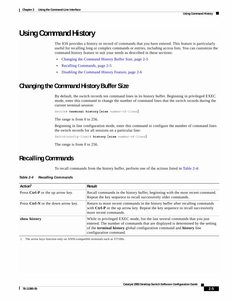
Chapter 2 Using the Command-Line InterfaceUsing Command History
Using Command HistoryThe IOS provides a history or record of commands that you have entered. This feature is particularly useful for recalling long or complex commands or entries, including access lists. You can customize the command history feature to suit your needs as described in these sections:
• Changing the Command History Buffer Size, page 2-5
• Recalling Commands, page 2-5
• Disabling the Command History Feature, page 2-6
Changing the Command History Buffer SizeBy default, the switch records ten command lines in its history buffer. Beginning in privileged EXEC mode, enter this command to change the number of command lines that the switch records during the current terminal session:
Switch# terminal history [size number-of-lines]
The range is from 0 to 256.
Beginning in line configuration mode, enter this command to configure the number of command lines the switch records for all sessions on a particular line:
Switch(config-line)# history [size number-of-lines]
The range is from 0 to 256.
Recalling CommandsTo recall commands from the history buffer, perform one of the actions listed in Table 2-4:
Table 2-4 Recalling Commands
Action1
1. The arrow keys function only on ANSI-compatible terminals such as VT100s.
Result
Press Ctrl-P or the up arrow key. Recall commands in the history buffer, beginning with the most recent command. Repeat the key sequence to recall successively older commands.
Press Ctrl-N or the down arrow key. Return to more recent commands in the history buffer after recalling commands with Ctrl-P or the up arrow key. Repeat the key sequence to recall successively more recent commands.
show history While in privileged EXEC mode, list the last several commands that you just entered. The number of commands that are displayed is determined by the setting of the terminal history global configuration command and history line configuration command.
2-5Catalyst 2950 Desktop Switch Software Configuration Guide
78-11380-05

Chapter 2 Using the Command-Line InterfaceUsing Editing Features
Disabling the Command History FeatureThe command history feature is automatically enabled.
To disable the feature during the current terminal session, enter the terminal no history privileged EXEC command.
To disable command history for the line, enter the no history line configuration command.
Using Editing FeaturesThis section describes the editing features that can help you manipulate the command line. It contains these sections:
• Enabling and Disabling Editing Features, page 2-6
• Editing Commands through Keystrokes, page 2-7
• Editing Command Lines that Wrap, page 2-8
Enabling and Disabling Editing FeaturesAlthough enhanced editing mode is automatically enabled, you can disable it.
To re-enable the enhanced editing mode for the current terminal session, enter this command in privileged EXEC mode:
Switch# terminal editing
To reconfigure a specific line to have enhanced editing mode, enter this command in line configuration mode:
Switch(config-line)# editing
To globally disable enhanced editing mode, enter this command in line configuration mode:
Switch(config-line)# no editing
2-6Catalyst 2950 Desktop Switch Software Configuration Guide
78-11380-05

Chapter 2 Using the Command-Line InterfaceUsing Editing Features
Editing Commands through KeystrokesTable 2-5 shows the keystrokes that you need to edit command lines.
Table 2-5 Editing Commands through Keystrokes
Capability Keystroke1 Purpose
Move around the command line to make changes or corrections.
Press Ctrl-B, or press the left arrow key.
Move the cursor back one character.
Press Ctrl-F, or press the right arrow key.
Move the cursor forward one character.
Press Ctrl-A. Move the cursor to the beginning of the command line.
Press Ctrl-E. Move the cursor to the end of the command line.
Press Esc B. Move the cursor back one word.
Press Esc F. Move the cursor forward one word.
Press Ctrl-T. Transpose the character to the left of the cursor with the character located at the cursor.
Recall commands from the buffer and paste them in the command line. The switch provides a buffer with the last ten items that you deleted.
Press Ctrl-Y. Recall the most recent entry in the buffer.
Press Esc Y. Recall the next buffer entry.
The buffer contains only the last 10 items that you have deleted or cut. If you press Esc Y more than ten times, you cycle to the first buffer entry.
Delete entries if you make a mistake or change your mind.
Press the Delete or Backspace key.
Erase the character to the left of the cursor.
Press Ctrl-D. Delete the character at the cursor.
Press Ctrl-K. Delete all characters from the cursor to the end of the command line.
Press Ctrl-U or Ctrl-X. Delete all characters from the cursor to the beginning of the command line.
Press Ctrl-W. Delete the word to the left of the cursor.
Press Esc D. Delete from the cursor to the end of the word.
Capitalize or lowercase words or capitalize a set of letters.
Press Esc C. Capitalize at the cursor.
Press Esc L. Change the word at the cursor to lowercase.
Press Esc U. Capitalize letters from the cursor to the end of the word.
Designate a particular keystroke as an executable command, perhaps as a shortcut.
Press Ctrl-V or Esc Q.
2-7Catalyst 2950 Desktop Switch Software Configuration Guide
78-11380-05

Chapter 2 Using the Command-Line InterfaceUsing Editing Features
Editing Command Lines that WrapYou can use a wraparound feature for commands that extend beyond a single line on the screen. When the cursor reaches the right margin, the command line shifts ten spaces to the left. You cannot see the first ten characters of the line, but you can scroll back and check the syntax at the beginning of the command.
To scroll back to the beginning of the command entry, press Ctrl-B or the left arrow key repeatedly. You can also press Ctrl-A to immediately move to the beginning of the line.
Note The arrow keys function only on ANSI-compatible terminals such as VT100s.
In this example, the access-list global configuration command entry extends beyond one line. When the cursor first reaches the end of the line, the line is shifted ten spaces to the left and redisplayed. The dollar sign ($) shows that the line has been scrolled to the left. Each time the cursor reaches the end of the line, the line is again shifted ten spaces to the left.
Switch(config)# access-list 101 permit tcp 131.108.2.5 255.255.255.0 131.108.1Switch(config)# $ 101 permit tcp 131.108.2.5 255.255.255.0 131.108.1.20 255.25Switch(config)# $t tcp 131.108.2.5 255.255.255.0 131.108.1.20 255.255.255.0 eqSwitch(config)# $108.2.5 255.255.255.0 131.108.1.20 255.255.255.0 eq 45
After you complete the entry, press Ctrl-A to check the complete syntax before pressing the Return key to execute the command. The dollar sign ($) appears at the end of the line to show that the line has been scrolled to the right:
Switch(config)# access-list 101 permit tcp 131.108.2.5 255.255.255.0 131.108.1$
The software assumes you have a terminal screen that is 80 columns wide. If you have a width other than that, use the terminal width privileged EXEC command to set the width of your terminal.
Scroll down a line or screen on displays that are longer than the terminal screen can display.
Note The More prompt is used for any output that has more lines than can be displayed on the terminal screen, including show command output. You can use the Return and Space bar keystrokes whenever you see the More prompt.
Press the Return key. Scroll down one line.
Press the Space bar. Scroll down one screen.
Redisplay the current command line if the switch suddenly sends a message to your screen.
Press Ctrl-L or Ctrl-R. Redisplay the current command line.
1. The arrow keys function only on ANSI-compatible terminals such as VT100s.
Table 2-5 Editing Commands through Keystrokes (continued)
Capability Keystroke1 Purpose
2-8Catalyst 2950 Desktop Switch Software Configuration Guide
78-11380-05

Chapter 2 Using the Command-Line InterfaceSearching and Filtering Output of show and more Commands
Use line wrapping with the command history feature to recall and modify previous complex command entries. For information about recalling previous command entries, see the “Editing Commands through Keystrokes” section on page 2-7.
Searching and Filtering Output of show and more CommandsYou can search and filter the output for show and more commands. This is useful when you need to sort through large amounts of output or if you want to exclude output that you do not need to see.
To use this functionality, enter a show or more command followed by the pipe character (|), one of the keywords begin, include, or exclude, and an expression that you want to search for or filter out:
command | {begin | include | exclude} regular-expression
Expressions are case sensitive. For example, if you enter | exclude output, the lines that contain output are not displayed, but the lines that contain Output are displayed.
This example shows how to include in the output display only lines where the expression protocol appears:
Switch# show interfaces | include protocolVlan1 is up, line protocol is upVlan10 is up, line protocol is downGigabitEthernet0/1 is up, line protocol is downGigabitEthernet0/2 is up, line protocol is up
Accessing the CLIBefore you can access the CLI, you need to connect a terminal or PC to the switch console port and power on the switch as described in the hardware installation guide that shipped with your switch. Then, to understand the boot process and the options available for assigning IP information, see Chapter 4, “Assigning the Switch IP Address and Default Gateway.”
If your switch is already configured, you can access the CLI through a local console connection or through a remote Telnet session, but your switch must first be configured for this type of access. For more information, see the “Setting a Telnet Password for a Terminal Line” section on page 7-5.
You can establish a connection with the switch in one of two ways:
• Connecting the switch console port to a management station or dial-up modem. For information about connecting to the console port, refer to the switch hardware installation guide.
• Using any Telnet TCP/IP package from a remote management station. The switch must have network connectivity with the Telnet client, and the switch must have an enable secret password configured.
For information about configuring the switch for Telnet access, see the “Setting a Telnet Password for a Terminal Line” section on page 7-5. The switch supports up to 16 simultaneous Telnet sessions. Changes made by one Telnet user are reflected in all other Telnet sessions.
After you connect through the console port or through a Telnet session, the user EXEC prompt appears on the management station.
2-9Catalyst 2950 Desktop Switch Software Configuration Guide
78-11380-05

Chapter 2 Using the Command-Line InterfaceAccessing the CLI from a Browser
Accessing the CLI from a BrowserThis procedure assumes you have met the software requirements (including browser and Java plug-in configurations) and have assigned IP information and a Telnet password to the switch or command switch, as described in the release notes.
To access the CLI from a web browser, follow these steps:
Step 1 Start one of the supported browsers.
Step 2 In the URL field, enter the IP address of the command switch.
Step 3 When the Cisco Systems Access page appears, click Telnet to start a Telnet session.
You can also access the CLI by clicking Monitor the router- HTML access to the command line interface from the Cisco Systems Access page. For information about the Cisco Systems Access page, see the “Accessing CMS” section in the release notes.
Step 4 Enter the switch password.
The user EXEC prompt appears on the management station.
Note Copies of the CMS pages that you display are saved in your browser memory cache until you exit the browser session. A password is not required to redisplay these pages, including the Cisco Systems Access page. You can access the CLI by clicking Web Console - HTML access to the command line interface from a cached copy of the Cisco Systems Access page. To prevent unauthorized access to CMS and the CLI, exit your browser to end the browser session.
2-10Catalyst 2950 Desktop Switch Software Configuration Guide
78-11380-05

Catalyst 2950 Deskto78-11380-05
C H A P T E R 3
Getting Started with CMSThis chapter provides these topics about the Cluster Management Suite (CMS) software:
• Features, page 3-2
• Front Panel View, page 3-4
• Topology View, page 3-9
• Menus and Toolbar, page 3-14
• Interaction Modes, page 3-23
• Wizards, page 3-24
• Online Help, page 3-25
• CMS Window Components, page 3-26
• Accessing CMS, page 3-28
• Verifying Your Changes, page 3-30
• Saving Your Configuration, page 3-30
• Restoring Your Configuration, page 3-31
• CMS Preferences, page 3-31
• Using Different Versions of CMS, page 3-31
• Where to Go Next, page 3-32
Note • For system requirements and for browser and Java plug-in configuration procedures, refer to the release notes.
• For procedures for using CMS, refer to the online help.
Note This chapter describes CMS on the Catalyst 2950 switches. Refer to the appropriate switch documentation for descriptions of the web-based management software used on other Catalyst switches.
3-1p Switch Software Configuration Guide

Chapter 3 Getting Started with CMSFeatures
FeaturesCMS provides these features (Figure 3-1) for managing switch clusters and individual switches from Web browsers such as Netscape Communicator or Microsoft Internet Explorer:
• Two views of your network that can be displayed at the same time:
– The Front Panel view displays the front-panel image of a specific switch or the front-panel images of all switches in a cluster. From this view, you can select multiple ports or multiple switches and configure them with the same settings.
When CMS is launched from a command switch, the Front Panel view displays the front-panel images of all switches in the cluster. When CMS is launched from a noncommand switch, the Front Panel view displays only the front panel of the specific switch.
Note CMS from a standalone switch or from a noncommand switch is referred to as Device Manager (also referred to as Switch Manager). Device Manager is for configuring an individual switch. When you select Device Manager for a specific switch in the cluster, you launch a separate CMS session. The Device Manager interface can vary between the Catalyst switch platforms.
– The Topology view displays a network map that uses icons that represent switch clusters, cluster members, cluster candidates, neighboring devices that are not eligible to join a cluster, and link types. From this view, you can select multiple switches and configure them to run with the same settings. You can also display link information in the form of link reports and link graphs.
This view is available only when CMS is launched from a command switch.
• Menus and toolbar to access configuration and management options:
– The menu bar provides the complete list of options for managing a single switch and switch clusters.
– The toolbar provides buttons for commonly used switch and cluster configuration options and information windows such as legends and online help.
– The port popup menu, in the Front Panel view, provides options specific for configuring and monitoring switch ports.
– The device popup menu, in either the Front Panel or the Topology views, provides switch and cluster configuration and monitoring options.
– The candidate, member, and link popup menus provide options for configuring and monitoring devices and links in the Topology view.
The toolbar and popup menus provide quick ways to access frequently used menu-bar options.
• Tools to simplify configuration tasks:
– Interactive modes—guide mode and expert mode—that control the presentation of some complex configuration options
– Wizards that require minimal information from you to configure some complex features
– Comprehensive online help that provides high-level concepts and procedures for performing tasks from the window
3-2Catalyst 2950 Desktop Switch Software Configuration Guide
78-11380-05

Chapter 3 Getting Started with CMSFeatures
• Two levels of access to the configuration options: read-write access for users allowed to change switch settings; read-only access for users allowed to only view switch settings
• Consistent set of GUI components (such as tabs, buttons, drop-down lists, tables, and so on) for a uniform approach to viewing and setting configuration parameters
Figure 3-1 CMS Features
Menu bar
Toolbar Move the cursor over the icon to display the tool tip. For example,
the button displays the legend of icons and color codes.
Click Guide or Expert interaction
mode to change how some configuration
options will be presented to you. 65
282
Front Panel view of the cluster.
Topology view of the cluster.
cluster1
6571
7
3-3Catalyst 2950 Desktop Switch Software Configuration Guide
78-11380-05

Chapter 3 Getting Started with CMSFront Panel View
Front Panel ViewWhen CMS is launched from a command switch, the Front Panel view displays the front-panel images of all switches in the cluster (Figure 3-2). When CMS is launched from a standalone or noncommand member switch, the Front Panel view displays only the front panel of the specific switch (Figure 3-3).
Figure 3-2 Front Panel View from a Command Switch
Figure 3-3 Front Panel View from a Standalone Switch
Cluster tree. Right-click a member switch image to display
the device pop-up menu, and select an
option to view or change system-related settings.
Right-click the command switch
image to display the cluster pop-up menu, and select a cluster-
related option.
cluster1
6571
8
10.1.1.2
2950-24
Right-click a port to display the port pop-up
menu, and select an option to view or change
port-related settings.
Press Ctrl, and then left-click ports to select multiple ports. The color of the port LED reflects
port or link status.
LEDs display the current port mode
and the status of the switch and
connected RPS.
Left-click the Mode button to change
the meaning of the port LEDs.
6571
9
2950-24
3-4Catalyst 2950 Desktop Switch Software Configuration Guide
78-11380-05

Chapter 3 Getting Started with CMSFront Panel View
Cluster TreeThe cluster tree (Figure 3-2) appears in the left frame of the Front Panel view and shows the name of the cluster and a list of its members. The sequence of the cluster-tree icons (Figure 3-4) mirror the sequence of the front-panel images. You can change the sequence by selecting View > Arrange Front Panel. The colors of the devices in the cluster tree show the status of the devices (Table 3-1).
If you want to configure switch or cluster settings on one or more switches, select the appropriate front-panel images.
• To select a front-panel image, click either the cluster-tree icon or the corresponding front-panel image. The front-panel image is then highlighted with a yellow outline.
• To select multiple front-panel images, press the Ctrl key, and left-click the cluster-tree icons or the front-panel images. To deselect an icon or image, press the Ctrl key, and left-click the icon or image.
If the cluster has many switches, you might need to scroll down the window to display the rest of the front-panel images. Instead of scrolling, you can click an icon in the cluster tree, and CMS then scrolls and displays the corresponding front-panel image.
Figure 3-4 Cluster-Tree Icons
Front-Panel ImagesYou can manage the switch from a remote station by using the front-panel images. The front-panel images are updated based on the network polling interval that you set from CMS > Preferences.
This section includes descriptions of the LED images. Similar descriptions of the switch LEDs are provided in the switch hardware installation guide.
Note The Preferences window is available if your switch access level is read-only. For more information about the read-only access mode, see the “Access Modes in CMS” section on page 3-29.
Table 3-1 Cluster Tree Icon Colors
Color Device Status
Green Switch is operating normally.
Yellow The internal fan of the switch is not operating, or the switch is receiving power from an RPS.
Red Switch is not powered up, has lost power, or the command switch is unable to communicate with the member switch.
3-5Catalyst 2950 Desktop Switch Software Configuration Guide
78-11380-05

Chapter 3 Getting Started with CMSFront Panel View
Figure 3-5 shows the port icons as they appear in the front-panel images. To select a port, click the port on the front-panel image. The port is then highlighted with a yellow outline. To select multiple ports, you can:
• Press the left mouse button, drag the pointer over the group of ports that you want to select, and then release the mouse button.
• Press the Ctrl key, and click the ports that you want to select.
• Right-click a port, and select Select All Ports from the port popup menu.
Figure 3-5 Port Icons
Table 3-2 describes the colors representing the wavelengths on the CWDM GBIC modules. For port status LED information, see the “Port Modes and LEDs” section on page 3-7.
Redundant Power System LED
The Redundant Power System (RPS) LED shows the RPS status (Table 3-3). Certain switches in the switch cluster use a specific RPS model:
• Cisco RPS 300 (model PWR300-AC-RPS-N1)—Catalyst 2900 LRE XL, Catalyst 2950, Catalyst 3524-PWR XL, and Catalyst 3550 switches
• Cisco RPS 600 (model PWR600-AC-RPS)—Catalyst 2900 XL and Catalyst 3500 XL switches, except the Catalyst 2900 LRE XL and Catalyst 3524-PWR XL switches
Refer to the appropriate switch hardware documentation for RPS descriptions specific for the switch.
Table 3-2 Port Icon Colors for the CWDM GBIC Module Ports
Wavelength Color
1470 nanometers (nm) Gray
1490 nm Violet
1510 nm Blue
1530 nm Green
1550 nm Yellow
1570 nm Orange
1590 nm Red
1610 nm Brown
3-6Catalyst 2950 Desktop Switch Software Configuration Guide
78-11380-05
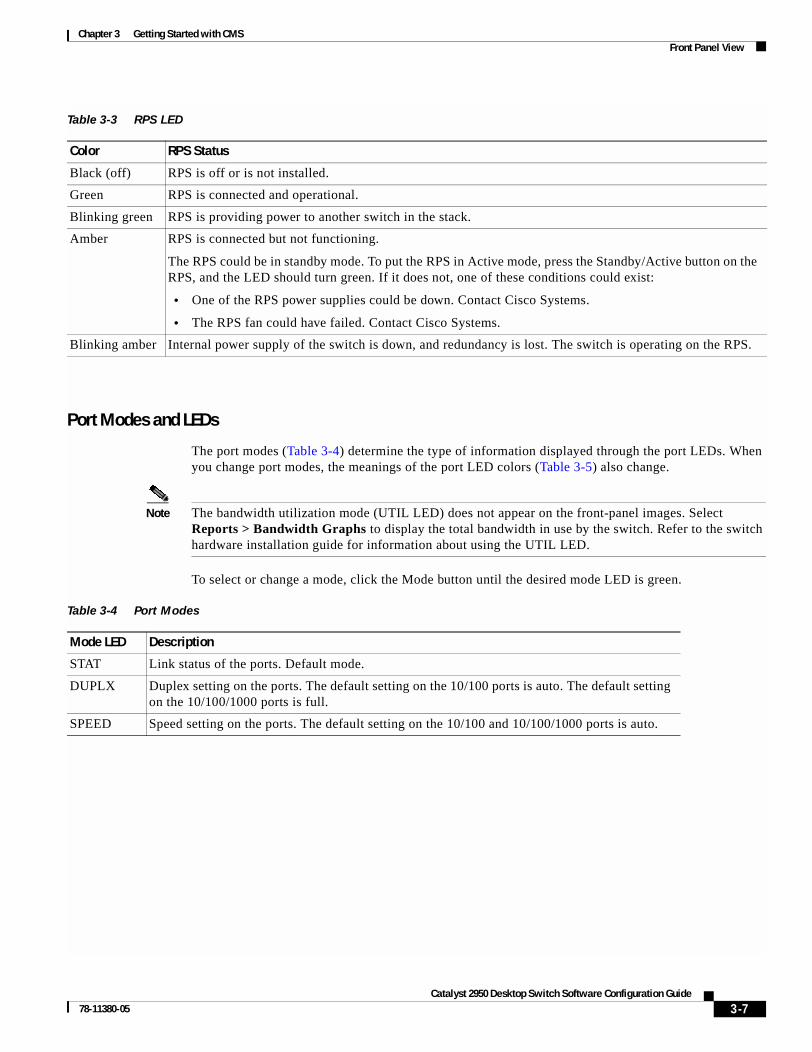
Chapter 3 Getting Started with CMSFront Panel View
Port Modes and LEDs
The port modes (Table 3-4) determine the type of information displayed through the port LEDs. When you change port modes, the meanings of the port LED colors (Table 3-5) also change.
Note The bandwidth utilization mode (UTIL LED) does not appear on the front-panel images. Select Reports > Bandwidth Graphs to display the total bandwidth in use by the switch. Refer to the switch hardware installation guide for information about using the UTIL LED.
To select or change a mode, click the Mode button until the desired mode LED is green.
Table 3-3 RPS LED
Color RPS Status
Black (off) RPS is off or is not installed.
Green RPS is connected and operational.
Blinking green RPS is providing power to another switch in the stack.
Amber RPS is connected but not functioning.
The RPS could be in standby mode. To put the RPS in Active mode, press the Standby/Active button on the RPS, and the LED should turn green. If it does not, one of these conditions could exist:
• One of the RPS power supplies could be down. Contact Cisco Systems.
• The RPS fan could have failed. Contact Cisco Systems.
Blinking amber Internal power supply of the switch is down, and redundancy is lost. The switch is operating on the RPS.
Table 3-4 Port Modes
Mode LED Description
STAT Link status of the ports. Default mode.
DUPLX Duplex setting on the ports. The default setting on the 10/100 ports is auto. The default setting on the 10/100/1000 ports is full.
SPEED Speed setting on the ports. The default setting on the 10/100 and 10/100/1000 ports is auto.
3-7Catalyst 2950 Desktop Switch Software Configuration Guide
78-11380-05

Chapter 3 Getting Started with CMSFront Panel View
VLAN Membership Modes
Ports in the Front Panel view are outlined by colors (Table 3-6) when you click Highlight VLAN Port Membership Modes on the Configure VLANs tab on the VLAN window (VLAN > VLAN > Configure VLANs). The colors show the VLAN membership mode of each port. The VLAN membership mode determines the kind of traffic the port carries and the number of VLANs it can belong to. For more information about these modes, see the “VLAN Port Membership Modes” section on page 13-3.
Note This feature is not supported on the Catalyst 1900 and Catalyst 2820 switches.
Table 3-5 Port LEDs
Port Mode Port LED Color Description
STAT Cyan (off) No link.
Green Link present.
Amber Link fault. Error frames can affect connectivity, and errors such as excessive collisions, CRC errors, and alignment and jabber errors are monitored for a link-fault indication.
Port is not forwarding. Port was disabled by management, by an address violation, or by Spanning Tree Protocol (STP).
Note After a port is reconfigured, the port LED can remain amber for up to 30 seconds as STP checks the switch for possible loops.
Brown No link and port is administratively shut down.
DUPLX Cyan (off) Port is operating in half-duplex mode.
Green Port is operating in full-duplex mode.
SPEED Cyan (off) Port is operating at 10 Mbps (10/100 ports) or no link (10/100/1000 ports and GBIC module ports).
Green Port is operating at 100 Mbps (10/100 ports) or 1000 Mbps (GBIC module ports).
Blinking green Port is operating at 1000 Mbps (10/100/1000 ports).
Table 3-6 VLAN Membership Modes
Mode Color
Static access Light green
Dynamic access Pink
802.1Q trunk Peach
Negotiate trunk White
3-8Catalyst 2950 Desktop Switch Software Configuration Guide
78-11380-05

Chapter 3 Getting Started with CMSTopology View
Topology ViewThe Topology view displays how the devices within a switch cluster are connected and how the switch cluster is connected to other clusters and devices. From this view, you can add and remove cluster members. This view provides two levels of detail of the network topology:
• When you right-click a cluster icon and select Expand Cluster, the Topology view displays the switch cluster in detail. This view shows the command switch and member switches in a cluster. It also shows candidate switches that can join the cluster. This view does not display the details of any neighboring switch clusters (Figure 3-6).
• When you right-click a command-switch icon and select Collapse Cluster, the cluster is collapsed and represented by a single icon. The view shows how the cluster is connected to other clusters, candidate switches, and devices that are not eligible to join the cluster (such as routers, access points, IP phones, and so on) (Figure 3-7).
Note The Topology view displays only the switch cluster and network neighborhood of the specific command or member switch that you access. To display a different switch cluster, you need to access the command switch or member switch of that cluster.
You can arrange the device icons in this view. To move a device icon, click and drag the icon. To select multiple device icons, you can either:
• Press the left mouse button, drag the pointer over the group of device icons that you want to select, and then release the mouse button.
• Press the Ctrl key, and click the device icons that you want to select.
After selecting the icons, drag the icons to any area in the view.
3-9Catalyst 2950 Desktop Switch Software Configuration Guide
78-11380-05

Chapter 3 Getting Started with CMSTopology View
Figure 3-6 Expand Cluster View
Figure 3-7 Collapse Cluster View
Right-click alink icon to displaya link popup menu.
Cluster members of cluster1 and other devices connected to cluster1.
6572
2Right-click adevice icon to displaya device popup menu.
Devices connected to cluster1 that are not eligible to join the cluster.
Neighboring cluster connected to cluster1.
6572
3cluster1
3-10Catalyst 2950 Desktop Switch Software Configuration Guide
78-11380-05

Chapter 3 Getting Started with CMSTopology View
Topology IconsThe Topology view and the cluster tree use the same set of device icons to represent clusters, command and standby command switches, and member switches (Figure 3-8). The Topology view also uses additional icons to represent these types of neighboring devices:
• Customer premises equipment (CPE) devices that are connected to Long-Reach Ethernet (LRE) switches
• Devices that are not eligible to join the cluster, such as Cisco IP phones, Cisco access points, and Cisco Discovery Protocol (CDP)-capable hubs and routers
Note The System Switch Processor (SSP) card in the Cisco Integrated Communications System (ICS) 7750 appears as a Layer 2 switch. SSP cards are not eligible to join switch clusters.
• Devices that are identified as unknown devices, such as some Cisco devices and third-party devices
Tip Neighboring devices are only displayed if they are connected to cluster members. To display neighboring devices in the Topology view, either add the switch to which they are connected to a cluster, or enable that switch as a command switch.
Note Candidate switches are distinguished by the color of their device label. Device labels and their colors are described in the “Colors in the Topology View” section on page 3-12.
To select a device, click the icon. The icon is then highlighted. To select multiple devices, you can either:
• Press the left mouse button, drag the pointer over the group of icons that you want to select, and then release the mouse button.
• Press the Ctrl key, and click the icons that you want to select.
Figure 3-8 Topology-View Device Icons
The Topology view also uses a set of link icons (Figure 3-9) to show the link type and status between two devices. To select a link, click the link that you want to select. To select multiple links, press the Ctrl key, and click the links that you want to select.
3-11Catalyst 2950 Desktop Switch Software Configuration Guide
78-11380-05

Chapter 3 Getting Started with CMSTopology View
Figure 3-9 Topology-View Link Icons
Device and Link LabelsThe Topology view displays device and link information by using these labels:
• Cluster and switch names
• Switch MAC and IP addresses
• Link type between the devices
• Link speed and IDs of the interfaces on both ends of the link
When using these labels, keep these considerations in mind:
• The IP address displays only in the labels for the command switch and member switches.
• The label of a neighboring cluster icon only displays the IP address of the command-switch IP address.
• The displayed link speeds are the actual link speeds except on the LRE links, which display the administratively assigned speed settings.
You can change the label settings from the Topology Options window, which is displayed by selecting View > Topology Options.
Colors in the Topology ViewThe colors of the Topology view icons show the status of the devices and links (Table 3-7, Table 3-8, and Table 3-9).
3-12Catalyst 2950 Desktop Switch Software Configuration Guide
78-11380-05

Chapter 3 Getting Started with CMSTopology View
The color of a device label shows the cluster membership of the device (Table 3-10).
Topology Display OptionsYou can set the type of information displayed in the Topology view by changing the settings in the Topology Options window. To display this window, select View > Topology Options. From this window, you can select:
• Device icons that you want displayed in or filtered from the Topology View window
• Interface IDs and Actual Speed values that you want displayed in the Link window
• Host Names, IP addresses, and MAC address labels that you want displayed in the Node window
Table 3-7 Device Icon Colors
Icon Color Color Meaning
Green The device is operating.
Yellow1
1. Available only on the cluster members.
The internal fan of the switch is not operating, or the switch is receiving power from an RPS.
Red1 The device is not operating.
Table 3-8 Single Link Icon Colors
Link Color Color Meaning
Green Active link
Red Down or blocked link
Table 3-9 Multiple Link Icon Colors
Link Color Color Meaning
Both green All links are active.
One green; one red At least one link is active, and at least one other link is down or blocked.
Both red All links are down or blocked.
Table 3-10 Device Label Colors
Label Color Color Meaning
Green A cluster member, either a member switch or the command switch
Cyan A candidate switch that is eligible to join the cluster
Yellow An unknown device or a device that is not eligible to join the cluster
3-13Catalyst 2950 Desktop Switch Software Configuration Guide
78-11380-05

Chapter 3 Getting Started with CMSMenus and Toolbar
Menus and ToolbarThe configuration and monitoring options for configuring switches and switch clusters are available from menus and a toolbar.
Menu BarThe menu bar provides the complete list of options for managing a single switch and switch cluster.
Options displayed from the menu bar can vary:
Note The menu-bar options on a Catalyst 2950 switch change depending on whether the switch is running the enhanced software image (EI) or the standard image (SI). The footnotes in Table 3-11 list the options available if the switch is running the EI.
• Access modes affect the availability of features from CMS. The footnotes in Table 3-11 describe the availability of an option based on your access mode in CMS: read-only (access level 1–14) and read-write (access level 15). For more information about how access modes affect CMS, see the “Access Modes in CMS” section on page 3-29.
• The option for enabling a command switch is only available from a CMS session launched from a command-capable switch.
• Cluster management tasks, such as upgrading the software of groups of switches, are available only from a CMS session launched from a command switch.
• If you launch CMS from a specific switch, the menu bar displays the features supported only by that switch.
• If you launch CMS from a command switch, the menu bar displays the features supported on the switches in the cluster, with these exceptions:
– If the command switch is a Layer 3 switch, such as a Catalyst 3550 switch, the menu bar displays the features of all Layer 3 and Layer 2 switches in the cluster.
– If the command switch is a Layer 2 switch, such as a Catalyst 2950 or Catalyst 3500 XL switch, the menu bar displays the features of all Layer 2 switches in the cluster. The menu bar does not display Layer 3 features even if the cluster has Catalyst 3550 Layer 3 member switches.
3-14Catalyst 2950 Desktop Switch Software Configuration Guide
78-11380-05

Chapter 3 Getting Started with CMSMenus and Toolbar
Note • We strongly recommend that the highest-end, command-capable switch in the cluster be the command switch:
– If your switch cluster has a Catalyst 3550 switch, that switch should be the command switch.
– If your switch cluster has Catalyst 2900 XL, Catalyst 2950, and Catalyst 3500 XL switches, the Catalyst 2950 should be the command switch.
– If your switch cluster has Catalyst 1900, Catalyst 2820, Catalyst 2900 XL, and Catalyst 3500 XL switches, either the Catalyst 2900 XL or Catalyst 3500 XL should be the command switch.
• Standby command switches must meet these requirements:
– When the command switch is a Catalyst 3550 switch, all standby command switches must be Catalyst 3550 switches.
– When the command switch is a Catalyst 2950 switch running Release 12.1(9)EA1 or later, all standby command switches must be Catalyst 2950 switches running Release 12.1(9)EA1 or later.
– When the command switch is a Catalyst 2950 switch running Release 12.1(6)EA2 or later, all standby command switches must be Catalyst 2950 switches running Release 12.1(6)EA2 or later.
– When the command switch is running Release 12.0(5)WC2 or earlier, the standby command switches can be these switches: Catalyst 2900 XL, Catalyst 2950, and Catalyst 3500 XL switches.
We strongly recommend that the command switch and standby command switches are of the same switch platform and that both are running the same level of software (SI or EI). In the event of a failover, the standby command switch must support the same configuration and services that are running on the command switch.
– If you have a Catalyst 3550 command switch, the standby command switches should be Catalyst 3550 switches.
– If you have a Catalyst 2950 command switch, the standby command switches should be Catalyst 2950 switches.
– If you have a Catalyst 2900 XL or Catalyst 3500 XL command switch, the standby command switches should be Catalyst 2900 XL and Catalyst 3500 XL switches.
Refer to the release notes for the Catalyst switches that can be part of a switch cluster.
Note Unless noted otherwise, Table 3-11 lists the menu-bar options available from a Catalyst 2950 command switch when the cluster contains only Catalyst 2950 member switches. The menu bar of the command switch displays all menu-bar options available from the cluster, including options from member switches from other cluster-capable switch platforms.
3-15Catalyst 2950 Desktop Switch Software Configuration Guide
78-11380-05

Chapter 3 Getting Started with CMSMenus and Toolbar
Table 3-11 Menu Bar
Menu-Bar Options Task
CMS
Page Setup Set default document printer properties to be used when printing from CMS.
Print Preview View the way the CMS window or help file will appear when printed.
Print Print a CMS window or help file.
Guide Mode/Expert Mode1 Select which interaction mode to use when you select a configuration option.
Preferences2 Set CMS display properties, such as polling intervals, the default views to open at startup, and the color of administratively shutdown ports.
Administration
IP Addresses2 Configure IP information for a switch.
SNMP2 Enable and disable Simple Network Management Protocol (SNMP), enter community strings, and configure end stations as trap managers.
System Time2 Configure the system time or configure the Network Time Protocol (NTP).
HTTP Port2 Configure the Hypertext Transfer Protocol (HTTP) port number.
Users and Passwords Configure usernames and passwords for privilege levels 0 to 15.
Console Baud Rate2 Change the baud rate for the switch console port.
MAC Addresses2 Enter dynamic, secure, and static addresses in a switch address table. You can also define the forwarding behavior of static addresses.
ARP2 Display the device Address Resolution Protocol (ARP) table, and configure the ARP cache timeout setting.
Save Configuration1 Save the configuration for the cluster or switch to Flash memory.
Restore Configuration Restore the configuration file to one or more switches in the cluster.
Software Upgrade1 Upgrade the software for the cluster or a switch.
System Reload1 Reboot the switch with the latest installed software.
Event Notification Create notification IDs that generate e-mail notifications when system events occur.
Cluster
Cluster Manager3 Launch a CMS session from the member switch.
Create Cluster1 4 Designate a command switch, and name a cluster.
Delete Cluster1 5 Delete a cluster.
Add to Cluster1 5 Add a candidate to a cluster.
Remove from Cluster1 5 Remove a member from the cluster.
Standby Command Switches2 5 Create a Hot Standby Router Protocol (HSRP) standby group to provide command-switch redundancy.
Hop Count2 5 Enter the number of hops away that a command switch looks for members and for candidate switches.
Device
Device Manager5 Launch Device Manager for a specific switch.
Host Name1 Change the host name of a switch.
STP2 Display and configure STP parameters for a switch.
3-16Catalyst 2950 Desktop Switch Software Configuration Guide
78-11380-05

Chapter 3 Getting Started with CMSMenus and Toolbar
IGMP Snooping2 Enable and disable Internet Group Management Protocol (IGMP) snooping and IGMP Immediate-Leave processing on the switch. Join or leave multicast groups, and configure multicast routers.
802.1X1 Configure 802.1X authentication of devices as they are attached to LAN ports in a point-to-point infrastructure.
ACL2 6
(guide mode available1)Create and maintain access control lists (ACLs), and attach ACLs to specific ports.
Security Wizard1 6 Filter certain traffic, such as HTTP traffic, to certain networks or devices. Restrict access to servers, networks, or application data from certain networks or devices.
QoS2
(guide mode available on some options1)
Display submenu options to enable and disable quality of service (QoS) and to configure or modify these parameters:
• Trust settings2
• Queues2
• Maps2 6
• Classes2 6(guide mode available1)
• Policies2 6(guide mode available1)
AVVID Wizards1 • Voice Wizard1—Configure a port to send or receive voice traffic.6
• Video Wizard1—Optimize multiple video servers for sending video traffic.6
• Data Wizard1—Provide a higher priority to specific applications.6
Port
Port Settings2 Display and configure port parameters on a switch.
Port Search Search for a port through its description.
Port Security1 Enable port security on a port.
EtherChannels2 Group ports into logical units for high-speed links between switches.
SPAN2 Enable Switched Port Analyzer (SPAN) port monitoring.
Protected Port2 Configure a port to prevent it from receiving bridged traffic from another port on the same switch.
Flooding Control2 Block the normal flooding of unicast and multicast packets, and enable the switch to block packet storms.
VLAN
VLAN2
(guide mode available1)Display VLAN membership, assign ports to VLANs, and configure 802.1Q trunks. Display and configure the VLAN Trunking Protocol (VTP) for interswitch VLAN membership.
Management VLAN2 Change the management VLAN on the switch.
VMPS2 Configure the VLAN Membership Policy Server (VMPS).
Voice VLAN2 Configure a port to use a voice VLAN for voice traffic, separating it from the VLANs for data traffic.
Reports
Inventory Display the device type, software version, IP address, and other switch information.
Table 3-11 Menu Bar (continued)
Menu-Bar Options Task
3-17Catalyst 2950 Desktop Switch Software Configuration Guide
78-11380-05

Chapter 3 Getting Started with CMSMenus and Toolbar
Port Statistics Display port statistics.
Bandwidth Graphs Display graphs that plot the total bandwidth in use by the switch.
Link Graphs Display a graph showing the bandwidth being used for the selected link.
Link Reports Display the link report for two connected devices. If one device is an unknown device or a candidate, only the cluster-member side of the link displays.
Resource Monitor6 Display masks for ACL and QoS policy maps.
System Messages Display the most recent system messages (IOS messages and switch-specific messages) sent by the switch software.
This option is available on the Catalyst 2950 or 3550 switches. It is not available from the Catalyst 2900 XL and Catalyst 3500 XL switches. You can display the system messages of the Catalyst 2900 XL and 3500 XL switches when they are in a cluster where the command switch is a Catalyst 2950 switch running Release 12.1(6)EA2 or later or a Catalyst 3550 switch running Release 12.1(8)EA1 or later. For more information about system messages, refer to the switch system message guide.
View
Refresh Update the views with the latest status.
Front Panel Display the Front Panel view.
Arrange Front Panel1 5 Rearrange the order in which switches appear in the Front Panel view.
Topology5 Display the Topology view.
Topology Options 5 Select the information to be displayed in the Topology view.
Automatic Topology Layout5 Request CMS to rearrange the topology layout.
Save Topology Layout1 5 Save the presentation of the cluster icons that you arranged in the Topology view to Flash memory.
Window List the open windows in your CMS session.
Help
Overview Obtain an overview of the CMS interface.
What’s New Obtain a description of the new CMS features.
Help For Active Window Display the help for the active open window. This is the same as clicking Help from the active window.
Contents List all of the available online help topics.
Legend Display the legend that describes the icons, labels, and links.
About Display the CMS version number.
1. Not available in read-only mode. For more information about the read-only and read-write access modes, see the “Access Modes in CMS” section on page 3-29.
2. Some options from this menu option are not available in read-only mode.
3. Available only from a Device Manager session on a cluster member.
4. Available only from a Device Manager session on a command-capable switch that is not a cluster member.
5. Available only from a cluster management session.
6. Available only from a switch running the EI.
Table 3-11 Menu Bar (continued)
Menu-Bar Options Task
3-18Catalyst 2950 Desktop Switch Software Configuration Guide
78-11380-05

Chapter 3 Getting Started with CMSMenus and Toolbar
ToolbarThe toolbar buttons display commonly-used switch and cluster configuration options and information windows such as legends and online help. Hover the cursor over an icon to display the feature. Table 3-12 describes the toolbar options, from left to right on the toolbar.
Table 3-12 Toolbar Buttons
Toolbar OptionKeyboard Shortcut Task
Print Ctrl-P Print a CMS window or help file.
Preferences1
1. Not available in read-only mode. For more information about the read-only and read-write access modes, see the “Access Modes in CMS” section on page 3-29.
Ctrl-R Set CMS display properties, such as polling intervals, the views to open at CMS startup, and the color of administratively shutdown ports.
Save Configuration2
2. Some options from this menu option are not available in read-only mode.
Ctrl-S Save the configuration for the cluster or switch to Flash memory.
Software Upgrade2 Ctrl-U Upgrade the software for the cluster or a switch.
Port Settings1 – Display and configure port parameters on a switch.
VLAN1 – Display VLAN membership, assign ports to VLANs, and configure 802.1Q trunks.
Inventory – Display the device type, the software version, the IP address, and other information about a switch.
Refresh – Update the views with the latest status.
Front Panel – Display the Front Panel view.
Topology3
3. Available only from a cluster-management session.
– Display the Topology view.
Topology Options3 – Select the information to be displayed in the Topology view.
Save Topology Layout2 3 – Save the presentation of the cluster icons that you arranged in the Topology view to Flash memory.
Legend – Display the legend that describes the icons, labels, and links.
Help For Active Window F1 key Display the help for the active open window. This is the same as clicking Help from the active window.
3-19Catalyst 2950 Desktop Switch Software Configuration Guide
78-11380-05

Chapter 3 Getting Started with CMSMenus and Toolbar
Front Panel View Popup MenusThese popup menus are available in the Front Panel view.
Device Popup Menu
You can display all switch and cluster configuration windows from the menu bar, or you can display commonly used configuration windows from the device popup menu (Table 3-13). To display the device popup menu, click the switch icon from the cluster tree or the front-panel image itself, and right-click.
Port Popup Menu
You can display all port configuration windows from the Port menu on the menu bar, or you can display commonly used port configuration windows from the port popup menu (Table 3-14). To display the port popup menu, click a specific port image, and right-click.
Table 3-13 Device Popup Menu
Popup Menu Option Task
Device Manager1
1. Available from a cluster member switch but not from the command switch.
Launch Device Manager for the switch.
Host Name2
2. Not available in read-only mode. For more information about the read-only mode, see the “Access Modes in CMS” section on page 3-29.
Change the name of the switch.
Delete Cluster2 3 4
3. Available only from the command switch.
4. Available only from a cluster-management session.
Delete a cluster.
Remove from Cluster2 4 Remove a member from the cluster.
Bandwidth Graphs Display graphs that plot the total bandwidth in use.
Properties Display information about the device and port on either end of the link and the state of the link.
Table 3-14 Port Popup Menu
Popup Menu Option Task
Port Settings1
1. Some options from this menu option are not available in read-only mode.
Display and configure port settings.
VLAN1 Define the VLAN mode for a port or ports and add ports to VLANs. Not available for the Catalyst 1900 and Catalyst 2820 switches.
Port Security1 2
2. Available on switches that support the Port Security feature.
Enable port security on a port.
Link Graphs3
3. Available only when there is an active link on the port (that is, the port LED is green when in port status mode).
Display a graph showing the bandwidth used by the selected link.
Select All Ports Select all ports on the switch for global configuration.
3-20Catalyst 2950 Desktop Switch Software Configuration Guide
78-11380-05

Chapter 3 Getting Started with CMSMenus and Toolbar
Topology View Popup MenusThese popup menus are available in the Topology view.
Link Popup Menu
You can display reports and graphs for a specific link displayed in the Topology view (Table 3-15). To display the link popup menu, click the link icon, and right-click.
The Link Report and Link Graph options are not available if at both ends of the link are
• Candidate switches
• Catalyst 1900 and Catalyst 2820 switches
• Devices that are not eligible to join the cluster
If multiple links are configured between two devices, when you click the link icon and right-click, the Multilink Content window appears (Figure 3-10). Click the link icon in this window, and right-click to display the link popup menu specific for that link.
Figure 3-10 Multilink Decomposer Window
Table 3-15 Link Popup Menu
Popup Menu Option Task
Link Report Display the link report for two connected devices. If one device is an unknown device or a candidate, only the cluster member side of the link displays.
Link Graph Display a graph showing the current bandwidth used by the selected link. You can change the graph polling interval by selecting CMS > Preferences.
Properties Display information about the device and port on either end of the link and the state of the link.
3-21Catalyst 2950 Desktop Switch Software Configuration Guide
78-11380-05

Chapter 3 Getting Started with CMSMenus and Toolbar
Device Popup Menus
Specific devices in the Topology view display a specific popup menu:
• Cluster (Table 3-16)
• Command switch (Table 3-17)
• Member or standby command switch (Table 3-18)
• Candidate switch with an IP address (Table 3-19)
• Candidate switch without an IP address (Table 3-20)
• Neighboring devices (Table 3-21)
Note The Device Manager option in these popup menus is available in read-only mode on Catalyst 2900 XL and Catalyst 3500 XL switches running Release 12.0(5)WC2 and later. It is also available on Catalyst 2950 switches running Release 12.1(6)EA2 and later and on Catalyst 3550 switch running Release 12.1(8)EA1 or later. It is not available on the Catalyst 1900 and Catalyst 2820 switches.
To display a device popup menu, click an icon, and right-click.
Table 3-16 Device Popup Menu of a Cluster Icon
Popup Menu Option Task
Expand cluster View a cluster-specific topology view.
Properties Display information about the device.
Table 3-17 Device Popup Menu of a Command-Switch Icon
Popup Menu Option Task
Collapse cluster View the neighborhood outside a specific cluster.
Host Name1
1. Not available in read-only mode. For more information about the read-only and read-write access modes, see the “Access Modes in CMS” section on page 3-29.
Change the host name of a switch.
Bandwidth Graphs Display graphs that plot the total bandwidth in use by the switch.
Properties Display information about the device.
Table 3-18 Device Popup Menu of a Member or Standby Command-Switch Icon
Popup Menu Option Task
Remove from Cluster1
1. Available only from a cluster-management session.
Remove a member from the cluster.
Host Name1 Change the host name of a switch.
Device Manager2
2. Available from a cluster member switch but not from the command switch.
Launch Device Manager for a switch.
Bandwidth Graphs Display graphs that plot the total bandwidth in use by the switch.
Properties Display information about the device.
3-22Catalyst 2950 Desktop Switch Software Configuration Guide
78-11380-05

Chapter 3 Getting Started with CMSInteraction Modes
Interaction ModesYou can change the interaction mode of CMS to either guide or expert mode. Guide mode steps you through each feature option and provides information about the parameter. Expert mode displays a configuration window in which you configure the feature options.
Table 3-19 Device Popup Menu of a Candidate-Switch Icon (When the Candidate Switch Has an
IP Address)
Popup Menu Option Task
Add to Cluster1 Add a candidate to a cluster.
Device Manager2 Launch Device Manager for a switch.
Properties Display information about the device.
1. Not available in read-only mode. For more information about the read-only and read-write access modes, see the “Access Modes in CMS” section on page 3-29.
2. Available from a cluster member switch but not from the command switch.
Table 3-20 Device Popup Menu of a Candidate-Switch Icon (When the Candidate Switch Does Not
Have an IP Address)
Popup Menu Option Task
Add to Cluster1
1. Not available in read-only mode. For more information about the read-only and read-write access modes, see the “Access Modes in CMS” section on page 3-29.
Add a candidate to a cluster.
Properties Display information about the device.
Table 3-21 Device Popup Menu of a Neighboring-Device Icon
Popup Menu Option Task
Device Manager1
1. Available from a cluster member switch but not from the command switch.
Access the web management interface of the device.
Note This option is available on Cisco access points, but not on Cisco IP phones, hubs, routers and on unknown devices such as some Cisco devices and third-party devices.
Disqualification Code Display the reason why the device could not join the cluster.
Properties Display information about the device.
3-23Catalyst 2950 Desktop Switch Software Configuration Guide
78-11380-05

Chapter 3 Getting Started with CMSWizards
Guide Mode
Note Guide mode is not available if your switch access level is read-only. For more information about the read-only access mode, see the “Access Modes in CMS” section on page 3-29.
Guide mode is for users who want a step-by-step approach for completing a specific configuration task. This mode is not available for all features. A menu-bar option that has a person icon means that guide mode is available for that option.
When you click Guide Mode and then select a menu-bar option that supports guide mode, CMS displays a specific parameter of the feature with information about the parameter field. To configure the feature, you provide the information that CMS requests in each step until you click Finish in the last step. Clicking Cancel at any time closes and ends the configuration task without applying any changes.
If Expert Mode is selected and you want to use guide mode, you must click Guide Mode before selecting an option from the menu bar, tool bar, or popup menu. If you change the interaction mode after selecting a configuration option, the mode change does not take effect until you select another configuration option.
Expert ModeExpert mode is for users who prefer to display all the parameter fields of a feature in a single CMS window. Information about the parameter fields is available by clicking the Help button.
Wizards
Note Wizards are not available if your switch access level is read-only. For more information about the read-only access mode, see the “Access Modes in CMS” section on page 3-29.
Wizards simplify some configuration tasks on the switch. Similar to the guide mode, wizards provide a step-by-step approach for completing a specific configuration task. Unlike guide mode, a wizard does not prompt you to provide information for all of the feature options. Instead, it prompts you to provide minimal information and then uses the default settings of the remaining options to set up default configurations.
Wizards are not available for all features. A menu-bar option that has wizard means that selecting that option launches the wizard for that feature.
3-24Catalyst 2950 Desktop Switch Software Configuration Guide
78-11380-05

Chapter 3 Getting Started with CMSTool Tips
Tool TipsCMS displays a popup message when you move your mouse over these devices:
• A yellow device icon in the cluster tree or in Topology view—A popup displays a fault message, such as that the RPS is faulty or that the switch is unavailable because you are in read-only mode.
• A red device icon in the cluster tree or in Topology view—A popup displays a message that the switch is down.
If you move your mouse over a table column heading, a popup displays the full heading.
Online HelpCMS provides comprehensive online help to assist you in understanding and performing configuration and monitoring tasks from the CMS windows (Figure 3-11).
• Feature help, available from the menu bar by selecting Help > Contents, provides background information and concepts on the features.
• Dialog-specific help, available from Help on the CMS windows, provides procedures for performing tasks.
• Index of help topics.
• Glossary of terms used in the online help.
You can send us feedback about the information provided in the online help. Click Feedback to display an online form. After completing the form, click Submit to send your comments to Cisco. We appreciate and value your comments.
Figure 3-11 Help Contents and Index
Information about the CMS interface.Feature help, such as concepts.
Legend of icons and color codes.Glossary of terms used in the online help. Click Back and Forward to redisplay
previously displayed pages. Click Feedback to send us your
comments about the online help.
Enter the firstletters of the topic,and click Find tosearch the index. 65
283
3-25Catalyst 2950 Desktop Switch Software Configuration Guide
78-11380-05

Chapter 3 Getting Started with CMSCMS Window Components
CMS Window ComponentsCMS windows consistently present configuration information. Figure 3-12 shows the components of a typical CMS window.
Figure 3-12 CMS Window Components
Host Name ListTo display or change the configuration of a cluster member, you need to select the specific switch from the Host Name drop-down list. The list appears in the configuration window of each feature and lists only the cluster members that support that feature. For example, the Host Name list on the VLAN
Click a tab to display more information.
Click a row to select it. Press Shift, and left-click another row to select contiguous multiple rows. Press Ctrl, and left-click rows to select non-contiguous rows.
Modify displays a secondary window from which you can change settings.
OK saves your changes and closes the window. Apply saves your changes and leaves
the window open.
Refresh refreshes the window to display the latest information.
Cancel closes the window without saving the changes.
Help displays help for the window and the menu of Help topics.
Select a cluster member from the Host Name list to display its settings.
7479
6
3-26Catalyst 2950 Desktop Switch Software Configuration Guide
78-11380-05

Chapter 3 Getting Started with CMSCMS Window Components
window does not include Catalyst 1900 and Catalyst 2820 switches even though they are part of the cluster. Similarly, the Host Name list on the LRE Profiles window only lists the LRE switches in the cluster.
Tabs, Lists, and TablesSome CMS windows have tabs that present different sets of information. Tabs are arranged like folder headings across the top of the window. Click the tab to display its information.
Listed information can often be changed by selecting an item from a list. To change the information, select one or more items, and click Modify. Changing multiple items is limited to those items that apply to at least one of the selections.
Some CMS windows present information in a table format. You can edit the information in these tables.
Note You can resize the width of the columns to display the column headings, or you can hover your cursor over the heading to display a popup description of the column.
Icons Used in WindowsSome window have icons for sorting information in tables, for showing which cells in a table are editable, and for displaying further information from Cisco.com (Figure 3-13).
Figure 3-13 Window Icons
ButtonsThese are the most common buttons that you use to change the information in a CMS window:
• OK—Save any changes and close the window. If you made no changes, the window closes. If CMS detects errors in your entry, the window remains open. For more information about error detection, see the “Error Checking” section on page 3-30.
• Apply—Save any changes made in the window and leave the window open. If you made no changes, the Apply button is disabled.
• Refresh—Update the CMS window with the latest status of the device. Unsaved changes are lost.
• Cancel—Do not save any changes made in the window and close the window.
• Help—Display procedures on performing tasks from the window.
• Modify—Display the secondary window for changing information on the selected item or items. You usually select an item from a list or table and click Modify.
3-27Catalyst 2950 Desktop Switch Software Configuration Guide
78-11380-05

Chapter 3 Getting Started with CMSAccessing CMS
Accessing CMSThis section assumes the following:
• You know the IP address and password of the command switch or a specific switch. This information is either:
– Assigned to the switch by following the setup program, as described in the release notes.
– Changed on the switch by following the information in the “Assigning Switch Information” section on page 4-2 and “Preventing Unauthorized Access to Your Switch” section on page 7-1. Considerations for assigning IP addresses and passwords to a command switch and cluster members are described in the “IP Addresses” section on page 6-16 and the “Passwords” section on page 6-17.
• You know your access privilege level to the switch.
• You have referred to the release notes for system requirements and have followed the procedures for installing the required Java plug-ins and configuring your browser.
Caution Copies of the CMS pages you display are saved in your browser memory cache until you exit the browser session. A password is not required to redisplay these pages, including the Cisco Systems Access page. You can access the CLI by clicking Monitor the router - HTML access to the command line interface from a cached copy of the Cisco Systems Access page. To prevent unauthorized access to CMS and the CLI, exit your browser to end the browser session.
Note If you have configured the Terminal Access Controller Access Control System Plus (TACACS+) or Remote Authentication Dial-In User Service (RADIUS) feature on the switch, you can still access the switch through CMS. For information about how inconsistent authentication configurations in switch clusters can affect access through CMS, see the “TACACS+ and RADIUS” section on page 6-18.
To access CMS, follow these steps:
Step 1 Enter the switch IP address and your privilege level in the browser Location field (Netscape Communicator) or Address field (Microsoft Internet Explorer). For example:http://10.1.126.45:184/level/14/
where 10.1.126.45 is the switch IP address, 184 is the HTTP port, and level/14 is the privilege level. You do not need to enter the HTTP port if the switch is using HTTP port 80 (the default) or enter the privilege level if you have read-write access to the switch (privilege level is 15). For information about the HTTP port, see the “HTTP Access to CMS” section on page 3-29. For information about privilege levels, see the “Access Modes in CMS” section on page 3-29.
Step 2 When prompted for a username and password, enter only the switch enable password. CMS prompts you a second time for a username and password. Enter only the enable password again.
If you configure a local username and password, make sure you enable it by using the ip http authentication global configuration command. Enter your username and password when prompted.
Step 3 Click Web Console.
If you access CMS from a standalone or member switch, Device Manager appears. If you access CMS from a command switch, you can display the Front Panel and Topology views.
3-28Catalyst 2950 Desktop Switch Software Configuration Guide
78-11380-05

Chapter 3 Getting Started with CMSAccessing CMS
Access Modes in CMSCMS provides two levels of access to the configuration options: read-write access and read-only access. Privilege levels 0 to 15 are supported.
• Privilege level 15 provides you with read-write access to CMS.
• Privilege levels 1 to 14 provide you with read-only access to CMS. Any options in the CMS windows, menu bar, toolbar, and popup menus that change the switch or cluster configuration are not shown in read-only mode.
• Privilege level 0 denies access to CMS.
If you do not include a privilege level when you access CMS, the switch verifies if you have privilege-level 15. If you do not, you are denied access to CMS. If you do have privilege-level 15, you are granted read-write access. Therefore, you do not need to include the privilege level if it is 15. Entering zero denies access to CMS. For more information about privilege levels, see the “Preventing Unauthorized Access to Your Switch” section on page 7-1.
Note • If your cluster has these member switches running earlier software releases and if you have read-only access to these member switches, some configuration windows for those switches display incomplete information:
– Catalyst 2900 XL or Catalyst 3500 XL member switches running Release 12.0(5)WC2 or earlier
– Catalyst 2950 member switches running Release 12.0(5)WC2 or earlier
– Catalyst 3550 member switches running Release 12.1(6)EA1 or earlier
For more information about this limitation, refer to the release notes.
• These switches do not support read-only mode on CMS:
– Catalyst 1900 and Catalyst 2820
– Catalyst 2900 XL switches with 4-MB CPU DRAM
In read-only mode, these switches appear as unavailable devices and cannot be configured from CMS.
HTTP Access to CMSCMS uses Hypertext Transfer Protocol (HTTP), which is an in-band form of communication with the switch through any one of its Ethernet ports and that allows switch management from a standard web browser. The default HTTP port is 80.
If you change the HTTP port, you must include the new port number when you enter the IP address in the browser Location or Address field (for example, http://10.1.126.45:184 where 184 is the new HTTP port number).
Do not disable or otherwise misconfigure the port through which your management station is communicating with the switch. You might want to write down the port number to which you are connected. Changes to the switch IP information should be done with care.
For information about connecting to a switch port, refer to the switch hardware installation guide.
3-29Catalyst 2950 Desktop Switch Software Configuration Guide
78-11380-05

Chapter 3 Getting Started with CMSVerifying Your Changes
Verifying Your ChangesCMS provides notification cues to help you track and confirm the changes you make.
Change NotificationA green border around a field or table cell means that you made an unsaved change to the field or table cell. Previous information in that field or table cell is displayed in the window status bar. When you save the changes or if you cancel the change, the green border disappears.
Error CheckingA red border around a field means that you entered invalid data in the field. An error message also displays in the window status bar. When you enter valid data in the field, a green border replaces the red border until you either save or cancel the change.
If there is an error in communicating with the switch or if you make an error while performing an action, a message notifies you about the error.
Saving Your Configuration
Note The Save Configuration option is not available if your switch access level is read-only. For more information about the read-only access mode, see the “Access Modes in CMS” section on page 3-29.
Tip As you make cluster configuration changes (except for changes to the Topology view and in the Preferences window), make sure that you periodically save the configuration from the command switch. The configuration is saved on the command and member switches.
The front-panel images and CMS windows always display the running configuration of the switch. When you make a configuration change to a switch or switch cluster, the change becomes part of the running configuration. The change does not automatically become part of the configuration file, which is the startup configuration used each time the switch restarts. If you do not save your changes, they are lost when the switch restarts.
Note Catalyst 1900 and Catalyst 2820 switches automatically save configuration changes to Flash memory as they occur.
For CMS procedures for saving your switch configuration, refer to the online help.
3-30Catalyst 2950 Desktop Switch Software Configuration Guide
78-11380-05
Chapter 3 Getting Started with CMSRestoring Your Configuration
Restoring Your ConfigurationAfter you save a switch configuration, you can restore the configuration to one or more switches for these reasons:
• You made an incorrect change to the current running configuration and want to reload a saved configuration.
• You need to reload a switch after a switch failure or power failure.
• You want to copy the configuration of a switch to other switches.
For CMS procedures for restoring a switch configuration, refer to the online help.
CMS PreferencesWhen you exit from CMS, your CMS preferences are saved to your PC in a file called .cms_properties. You can copy this file to other PCs. The file is stored in a default configuration directory, such as C:\Documents and Settings\username. If you cannot locate the CMS preferences file, select Start > Search > For Files or Folders..., and search for .cms_properties.
Note In previous CMS versions, the preferences were saved in Flash memory when you exited from CMS.
Using Different Versions of CMSWhen managing switch clusters through CMS, remember that clusters can have a mix of switch models using different IOS releases and that CMS in earlier IOS releases and on different switch platforms might look and function differently from CMS in this IOS release.
When you select Device > Device Manager for a cluster member, a new browser session is launched, and the CMS version for that switch is displayed.
Here are examples of how CMS can differ between IOS releases and switch platforms:
• On Catalyst switches running Release 12.0(5)WC2 or earlier or Release 12.1(6)EA1 or earlier, the CMS versions in those software releases might appear similar but are not the same as this release. For example, the Topology view in this release is not the same as the Topology view or Cluster View in those earlier software releases.
• CMS on the Catalyst 1900 and Catalyst 2820 switches is referred to as Switch Manager. Cluster management options are not available on these switches. This is the earliest version of CMS.
Refer to the documentation specific to the switch and its IOS release for descriptions of the CMS version you are using.
3-31Catalyst 2950 Desktop Switch Software Configuration Guide
78-11380-05

Chapter 3 Getting Started with CMSWhere to Go Next
Where to Go NextBefore configuring the switch, refer to these places for start-up information:
• Switch release notes on Cisco.com:
– CMS software requirements
– Procedures for running the setup program
– Procedures for browser configuration
– Procedures for accessing CMS
• Chapter 4, “Assigning the Switch IP Address and Default Gateway”
• Chapter 7, “Administering the Switch”
The rest of this guide provides information about and CLI procedures for the software features supported in this release. For CMS procedures and window descriptions, refer to the online help.
3-32Catalyst 2950 Desktop Switch Software Configuration Guide
78-11380-05

Catalyst 2950 Deskto78-11380-05
C H A P T E R 4
Assigning the Switch IP Address and Default GatewayThis chapter describes how to create the initial switch configuration (for example, assign the switch IP address and default gateway information) by using a variety of automatic and manual methods.
Note For complete syntax and usage information for the commands used in this chapter, refer to the command reference for this release.
This chapter consists of these sections:
• Understanding the Boot Process, page 4-1
• Assigning Switch Information, page 4-2
• Checking and Saving the Running Configuration, page 4-10
Understanding the Boot ProcessBefore you can assign switch information (IP address, subnet mask, default gateway, secret and Telnet passwords, and so forth), you need to install and power on the switch as described in the hardware installation guide that shipped with your switch.
The normal boot process involves the operation of the boot loader software, which performs these activities:
• Performs low-level CPU initialization. It initializes the CPU registers, which control where physical memory is mapped, its quantity, its speed, and so forth.
• Performs power-on self-test (POST) for the CPU subsystem. It tests the CPU DRAM and the portion of the Flash device that makes up the Flash file system.
• Initializes the Flash file system on the system board.
• Loads a default operating system software image into memory and boots the switch.
The boot loader provides access to the Flash file system before the operating system is loaded. Normally, the boot loader is used only to load, uncompress, and launch the operating system. After the boot loader gives the operating system control of the CPU, the boot loader is not active until the next system reset or power-on.
4-1p Switch Software Configuration Guide

Chapter 4 Assigning the Switch IP Address and Default GatewayAssigning Switch Information
The boot loader also provides trap-door access into the system if the operating system has problems serious enough that it cannot be used. The trap-door mechanism provides enough access to the system so that if it is necessary, you can format the Flash file system, reinstall the operating system software image by using the XMODEM Protocol, recover from a lost or forgotten password, and finally restart the operating system. For more information, see the “Recovering from Corrupted Software” section on page 27-2 and the “Recovering from a Lost or Forgotten Password” section on page 27-2.
Before you can assign switch information, make sure you have connected a PC or terminal to the console port, and configured the PC or terminal-emulation software baud rate and character format to match those of the switch console port. For more information, refer to the hardware installation guide that shipped with your switch.
Assigning Switch InformationYou can assign IP information through the switch setup program, through a Dynamic Host Configuration Protocol (DHCP) server, or manually.
Use the switch setup program if you are a new user and want to be prompted for specific IP information. With this program, you can also configure a host name and an enable secret password. It gives you the option of assigning a Telnet password (to provide security during remote management) and configuring your switch as a command or member switch of a cluster or as a standalone switch. For more information about the setup program, refer to the release notes on Cisco.com.
Use a DHCP server for centralized control and automatic assignment of IP information once the server is configured.
Note If you are using DHCP, do not respond to any of the questions in the setup program until the switch receives the dynamically-assigned IP address and reads the configuration file.
Use the manual method of configuration if you are an experienced user familiar with the switch configuration steps; otherwise, use the setup program described earlier.
This section contains this configuration information:
• Default Switch Information, page 4-3
• Understanding DHCP-Based Autoconfiguration, page 4-3
• Manually Assigning IP Information, page 4-10
4-2Catalyst 2950 Desktop Switch Software Configuration Guide
78-11380-05

Chapter 4 Assigning the Switch IP Address and Default GatewayAssigning Switch Information
Default Switch InformationTable 4-1 shows the default switch information.
Understanding DHCP-Based AutoconfigurationThe DHCP provides configuration information to Internet hosts and internetworking devices. This protocol consists of two components: one for delivering configuration parameters from a DHCP server to a device and a mechanism for allocating network addresses to devices. DHCP is built on a client-server model, in which designated DHCP servers allocate network addresses and deliver configuration parameters to dynamically configured devices.
During DHCP-based autoconfiguration, your switch (DHCP client) is automatically configured at startup with IP address information and a configuration file.
With DHCP-based autoconfiguration, no DHCP client-side configuration is needed on your switch. However, you need to configure the DHCP server for various lease options associated with IP addresses. If you are using DHCP to relay the configuration file location on the network, you might also need to configure a Trivial File Transfer Protocol (TFTP) server and a Domain Name System (DNS) server.
The DHCP server can be on the same LAN or on a different LAN than the switch. If the DHCP server is running on a different LAN, you should configure a DHCP relay. A relay device forwards broadcast traffic between two directly connected LANs. A router does not forward broadcast packets, but it forwards packets based on the destination IP address in the received packet.
DHCP-based autoconfiguration replaces the BOOTP client functionality on your switch.
Table 4-1 Default Switch Information
Feature Default Setting
IP address and subnet mask No IP address or subnet mask are defined.
Default gateway No default gateway is defined.
Enable secret password No password is defined.
Host name The factory-assigned default host name is Switch.
Telnet password No password is defined.
Cluster command switch functionality Disabled.
Cluster name No cluster name is defined.
4-3Catalyst 2950 Desktop Switch Software Configuration Guide
78-11380-05

Chapter 4 Assigning the Switch IP Address and Default GatewayAssigning Switch Information
DHCP Client Request Process
When you boot your switch, the DHCP client is invoked and automatically requests configuration information from a DHCP server when the configuration file is not present on the switch.
Figure 4-1 shows the sequence of messages that are exchanged between the DHCP client and the DHCP server.
Figure 4-1 DHCP Client and Server Message Exchange
The client, Switch A, broadcasts a DHCPDISCOVER message to locate a DHCP server. The DHCP server offers configuration parameters (such as an IP address, subnet mask, gateway IP address, DNS IP address, a lease for the IP address, and so forth) to the client in a DHCPOFFER unicast message.
In a DHCPREQUEST broadcast message, the client returns a formal request for the offered configuration information to the DHCP server. The formal request is broadcast so that all other DHCP servers that received the DHCPDISCOVER broadcast message from the client can reclaim the IP addresses that they offered to the client.
The DHCP server confirms that the IP address has been allocated to the client by returning a DHCPACK unicast message to the client. With this message, the client and server are bound, and the client uses configuration information received from the server. The amount of information the switch receives depends on how you configure the DHCP server. For more information, see the “Configuring the DHCP Server” section on page 4-5.
If the configuration parameters sent to the client in the DHCPOFFER unicast message are invalid (a configuration error exists), the client returns a DHCPDECLINE broadcast message to the DHCP server.
The DHCP server sends the client a DHCPNAK denial broadcast message, which means that the offered configuration parameters have not been assigned, that an error has occurred during the negotiation of the parameters, or that the client has been slow in responding to the DHCPOFFER message (the DHCP server assigned the parameters to another client).
A DHCP client might receive offers from multiple DHCP or BOOTP servers and can accept any of the offers; however, the client usually accepts the first offer it receives. The offer from the DHCP server is not a guarantee that the IP address is allocated to the client; however, the server usually reserves the address until the client has had a chance to formally request the address. If the switch accepts replies from a BOOTP server and configures itself, the switch broadcasts, instead of unicasts, TFTP requests to obtain the switch configuration file.
Switch A
DHCPACK (unicast)
DHCPREQUEST (broadcast)
DHCPOFFER (unicast)
DHCPDISCOVER (broadcast)
DHCP server
5180
7
4-4Catalyst 2950 Desktop Switch Software Configuration Guide
78-11380-05

Chapter 4 Assigning the Switch IP Address and Default GatewayAssigning Switch Information
Configuring the DHCP Server
You should configure the DHCP server with reserved leases that are bound to each switch by the switch hardware address.
If you want the switch to receive IP address information, you must configure the DHCP server with these lease options:
• IP address of the client (required)
• Subnet mask of the client (required)
• DNS server IP address (optional)
• Router IP address (default gateway address to be used by the switch) (required)
If you want the switch to receive the configuration file from a TFTP server, you must configure the DHCP server with these lease options:
• TFTP server name (required)
• Boot filename (the name of the configuration file that the client needs) (recommended)
• Host name (optional)
Depending on the settings of the DHCP server, the switch can receive IP address information, the configuration file, or both.
If you do not configure the DHCP server with the lease options described earlier, it replies to client requests with only those parameters that are configured. If the IP address and subnet mask are not in the reply, the switch is not configured. If the router IP address or TFTP server name are not found, the switch might send broadcast, instead of unicast, TFTP requests. Unavailability of other lease options does not affect autoconfiguration.
The DHCP server can be on the same LAN or on a different LAN than the switch. If the DHCP server is running on a different LAN, you should configure a DHCP relay. For more information, see the “Configuring the Relay Device” section on page 4-6. If your DHCP server is a Cisco device, refer to the “IP Addressing and Services” section in the Cisco IOS IP and IP Routing Configuration Guide for Release 12.1.
Configuring the TFTP Server
Based on the DHCP server configuration, the switch attempts to download one or more configuration files from the TFTP server. If you configured the DHCP server to respond to the switch with all the options required for IP connectivity to the TFTP server, and if you configured the DHCP server with a TFTP server name, address, and configuration filename, the switch attempts to download the specified configuration file from the specified TFTP server.
If you did not specify the configuration filename, the TFTP server, or if the configuration file could not be downloaded, the switch attempts to download a configuration file by using various combinations of filenames and TFTP server addresses. The files include the specified configuration filename (if any) and these files: network-config, cisconet.cfg, hostname.config, or hostname.cfg, where hostname is the switch’s current hostname. The TFTP server addresses used include the specified TFTP server address (if any) and the broadcast address (255.255.255.255).
4-5Catalyst 2950 Desktop Switch Software Configuration Guide
78-11380-05

Chapter 4 Assigning the Switch IP Address and Default GatewayAssigning Switch Information
For the switch to successfully download a configuration file, the TFTP server must contain one or more configuration files in its base directory. The files can include these files:
• The configuration file named in the DHCP reply (the actual switch configuration file).
• The network-confg or the cisconet.cfg file (known as the default configuration files).
• The router-confg or the ciscortr.cfg file (These files contain commands common to all switches. Normally, if the DHCP and TFTP servers are properly configured, these files are not accessed.)
If you specify the TFTP server name in the DHCP server-lease database, you must also configure the TFTP server name-to-IP-address mapping in the DNS-server database.
If the TFTP server to be used is on a different LAN from the switch, or if it is to be accessed by the switch through the broadcast address (which occurs if the DHCP server response does not contain all the required information described earlier), a relay must be configured to forward the TFTP packets to the TFTP server. For more information, see the “Configuring the Relay Device” section on page 4-6. The preferred solution is to configure the DHCP server with all the required information.
Configuring the DNS
The DHCP server uses the DNS server to resolve the TFTP server name to an IP address. You must configure the TFTP server name-to-IP address map on the DNS server. The TFTP server contains the configuration files for the switch.
You can configure the IP addresses of the DNS servers in the lease database of the DHCP server from where the DHCP replies will retrieve them. You can enter up to two DNS server IP addresses in the lease database.
The DNS server can be on the same or on a different LAN as the switch. If it is on a different LAN, the switch must be able to access it through a router.
Configuring the Relay Device
You must configure a relay device when a switch sends broadcast packets that need to be responded to by a host on a different LAN. Examples of broadcast packets that the switch might send are DHCP, DNS, and in some cases, TFTP packets. You must configure this relay device to forward received broadcast packets on an interface to the destination host.
If the relay device is a Cisco router, enable IP routing (ip routing global configuration command), and configure helper addresses by using the ip helper-address interface configuration command.
For example, in Figure 4-2, configure the router interfaces as follows:
On interface 10.0.0.2:
router(config-if)# ip helper-address 20.0.0.2router(config-if)# ip helper-address 20.0.0.3router(config-if)# ip helper-address 20.0.0.4
On interface 20.0.0.1
router(config-if)# ip helper-address 10.0.0.1
4-6Catalyst 2950 Desktop Switch Software Configuration Guide
78-11380-05

Chapter 4 Assigning the Switch IP Address and Default GatewayAssigning Switch Information
Figure 4-2 Relay Device Used in Autoconfiguration
Obtaining Configuration Files
Depending on the availability of the IP address and the configuration filename in the DHCP reserved lease, the switch obtains its configuration information in these ways:
• The IP address and the configuration filename is reserved for the switch and provided in the DHCP reply (one-file read method).
The switch receives its IP address, subnet mask, TFTP server address, and the configuration filename from the DHCP server. The switch sends a unicast message to the TFTP server to retrieve the named configuration file from the base directory of the server, and upon receipt, completes its boot-up process.
• The IP address and the configuration filename is reserved for the switch, but the TFTP server address is not provided in the DHCP reply (one-file read method).
The switch receives its IP address, subnet mask, and the configuration filename from the DHCP server. The switch sends a broadcast message to a TFTP server to retrieve the named configuration file from the base directory of the server, and upon receipt, completes its boot-up process.
• Only the IP address is reserved for the switch and provided in the DHCP reply. The configuration filename is not provided (two-file read method).
The switch receives its IP address, subnet mask, and the TFTP server address from the DHCP server. The switch sends a unicast message to the TFTP server to retrieve the network-confg or cisconet.cfg default configuration file. (If the network-confg file cannot be read, the switch reads the cisconet.cfg file.)
The default configuration file contains the host names-to-IP-address mapping for the switch. The switch fills its host table with the information in the file and obtains its host name. If the host name is not found in the file, the switch uses the host name in the DHCP reply. If the host name is not specified in the DHCP reply, the switch uses the default Switch as its host name.
After obtaining its host name from the default configuration file or the DHCP reply, the switch reads the configuration file that has the same name as its host name (hostname-confg or hostname.cfg, depending on whether network-confg or cisconet.cfg was read earlier) from the TFTP server. If the cisconet.cfg file is read, the filename of the host is truncated to eight characters.
If the switch cannot read the network-confg, cisconet.cfg, or the hostname file, it reads the router-confg file. If the switch cannot read the router-confg file, it reads the ciscortr.cfg file.
Switch(DHCP client)
Cisco router(Relay)
4906
8
DHCP server TFTP server DNS server
20.0.0.2 20.0.0.3
20.0.0.110.0.0.2
10.0.0.1
20.0.0.4
4-7Catalyst 2950 Desktop Switch Software Configuration Guide
78-11380-05

Chapter 4 Assigning the Switch IP Address and Default GatewayAssigning Switch Information
Note The switch broadcasts TFTP server requests if the TFTP server is not obtained from the DHCP replies, if all attempts to read the configuration file through unicast transmissions fail, or if the TFTP server name cannot be resolved to an IP address.
Example Configuration
Figure 4-3 shows a sample network for retrieving IP information by using DHCP-based autoconfiguration.
Figure 4-3 DHCP-Based Autoconfiguration Network Example
Table 4-2 shows the configuration of the reserved leases on the DHCP server.
Switch 100e0.9f1e.2001
Cisco router
4906
6
Switch 200e0.9f1e.2002
Switch 300e0.9f1e.2003
DHCP server DNS server TFTP server(maritsu)
10.0.0.1
10.0.0.10
10.0.0.2 10.0.0.3
Switch 400e0.9f1e.2004
Table 4-2 DHCP Server Configuration
Switch-1 Switch-2 Switch-3 Switch-4
Binding key (hardware address)
00e0.9f1e.2001 00e0.9f1e.2002 00e0.9f1e.2003 00e0.9f1e.2004
IP address 10.0.0.21 10.0.0.22 10.0.0.23 10.0.0.24
Subnet mask 255.255.255.0 255.255.255.0 255.255.255.0 255.255.255.0
Router address 10.0.0.10 10.0.0.10 10.0.0.10 10.0.0.10
DNS server address 10.0.0.2 10.0.0.2 10.0.0.2 10.0.0.2
TFTP server name maritsu or 10.0.0.3 maritsu or 10.0.0.3 maritsu or 10.0.0.3 maritsu or 10.0.0.3
Boot filename (configuration file) (optional)
switch1-confg switch2-confg switch3-confg switch4-confg
Host name (optional) switch1 switch2 switch3 switch4
4-8Catalyst 2950 Desktop Switch Software Configuration Guide
78-11380-05

Chapter 4 Assigning the Switch IP Address and Default GatewayAssigning Switch Information
DNS Server Configuration
The DNS server maps the TFTP server name maritsu to IP address 10.0.0.3.
TFTP Server Configuration (on UNIX)
The TFTP server base directory is set to /tftpserver/work/. This directory contains the network-confg file used in the two-file read method. This file contains the host name to be assigned to the switch based on its IP address. The base directory also contains a configuration file for each switch (switch1-confg, switch2-confg, and so forth) as shown in this display:
prompt> cd /tftpserver/work/prompt> lsnetwork-confgswitch1-confgswitch2-confgswitch3-confgswitch4-confgprompt> cat network-confgip host switch1 10.0.0.21ip host switch2 10.0.0.22ip host switch3 10.0.0.23ip host switch4 10.0.0.24
DHCP Client Configuration
No configuration file is present on Switch 1 through Switch 4.
Configuration Explanation
In Figure 4-3, Switch 1 reads its configuration file as follows:
• It obtains its IP address 10.0.0.21 from the DHCP server.
• If no configuration filename is given in the DHCP server reply, Switch 1 reads the network-confg file from the base directory of the TFTP server.
• It adds the contents of the network-confg file to its host table.
• It reads its host table by indexing its IP address 10.0.0.21 to its host name (switch1).
• It reads the configuration file that corresponds to its host name; for example, it reads switch1-confg from the TFTP server.
Switches 2 through 4 retrieve their configuration files and IP addresses in the same way.
4-9Catalyst 2950 Desktop Switch Software Configuration Guide
78-11380-05

Chapter 4 Assigning the Switch IP Address and Default GatewayChecking and Saving the Running Configuration
Manually Assigning IP InformationBeginning in privileged EXEC mode, follow these steps to manually assign IP information to multiple switched virtual interfaces (SVIs) or ports:
To remove the switch IP address, use the no ip address interface configuration command. If you are removing the address through a Telnet session, your connection to the switch will be lost. To remove the default gateway address, use the no ip default-gateway global configuration command.
For information on setting the switch system name, protecting access to privileged EXEC commands, and setting time and calendar services, see Chapter 7, “Administering the Switch.”
Checking and Saving the Running ConfigurationYou can check the configuration settings you entered or changes you made by entering this privileged EXEC command:
Switch# show running-config
Building configuration...
Current configuration : 2081 bytes!version 12.1no service padservice timestamps debug uptimeservice timestamps log datetimeno service password-encryptionservice sequence-numbers
Command Purpose
Step 1 configure terminal Enter global configuration mode.
Step 2 interface vlan vlan-id Enter interface configuration mode, and enter the VLAN to which the IP information is assigned. The range is 1 to 4094 when the enhanced software image is installed and 1 to 1001 when the standard software image is installed; do not enter leading zeros.
Step 3 ip address ip-address subnet-mask Enter the IP address and subnet mask.
Step 4 exit Return to global configuration mode.
Step 5 ip default-gateway ip-address Enter the IP address of the next-hop router interface that is directly connected to the switch where a default gateway is being configured. The default gateway receives IP packets with unresolved destination IP addresses from the switch.
Once the default gateway is configured, the switch has connectivity to the remote networks with which a host needs to communicate.
Note When your switch is configured to route with IP, it does not need to have a default gateway set.
Step 6 end Return to privileged EXEC mode.
Step 7 show running-config Verify your entries.
Step 8 copy running-config startup-config (Optional) Save your entries in the configuration file.
4-10Catalyst 2950 Desktop Switch Software Configuration Guide
78-11380-05

Chapter 4 Assigning the Switch IP Address and Default GatewayChecking and Saving the Running Configuration
!hostname Switch!enable secret 5 $1$ej9.$DMUvAUnZOAmvmgqBEzIxE0!ip subnet-zero!vlan 3020cluster enable Test 0cluster member 1 mac-address 0030.9439.0900cluster member 2 mac-address 0001.425b.4d80!spanning-tree extend system-id!!interface Port-channel1no ip address!interface FastEthernet0/1 switchport mode access switchport voice vlan 400 switchport priority extend cos 5 no ip address spanning-tree portfast trunk!interface FastEthernet0/2 switchport mode access no ip address!...interface FastEthernet0/8 switchport mode access switchport voice vlan 350 no ip address spanning-tree portfast trunk!interface FastEthernet0/9 switchport mode access no ip address shutdown!interface FastEthernet0/10 switchport trunk native vlan 2 no ip address speed 100!interface FastEthernet0/11 switchport voice vlan 4046 no ip address shutdown spanning-tree portfast trunk!interface FastEthernet0/12 switchport mode access switchport voice vlan 4011 no ip address shutdown spanning-tree portfast trunk!interface GigabitEthernet0/1 no ip address shutdown!interface GigabitEthernet0/2
4-11Catalyst 2950 Desktop Switch Software Configuration Guide
78-11380-05

Chapter 4 Assigning the Switch IP Address and Default GatewayChecking and Saving the Running Configuration
no ip address shutdown!interface Vlan1 ip address 172.20.139.133 255.255.255.224 no ip route-cache!ip default-gateway 172.20.139.129ip http server!ip access-list extended CMP-NAT-ACL!snmp-server engineID local 8000000903000005742809C1snmp-server community public ROsnmp-server community public@es0 ROsnmp-server enable traps MAC-Notification!line con 0 password letmeinline vty 0 4 password letmein loginline vty 5 15 password letmein login!end
To store the configuration or changes you have made to your startup configuration in Flash memory, enter this privileged EXEC command:
Switch# copy running-config startup-configDestination filename [startup-config]?Building configuration...
This command saves the configuration settings that you made. If you fail to do this, your configuration will be lost the next time you reload the system. To display information stored in the NVRAM section of Flash memory, use the show startup-config or more startup-config privileged EXEC command.
4-12Catalyst 2950 Desktop Switch Software Configuration Guide
78-11380-05

Catalyst 2950 Deskto78-11380-05
C H A P T E R 5
Configuring IE2100 CNS AgentsThis chapter describes how to configure the Intelligence Engine 2100 (IE2100) Series Cisco Networking Services (CNS) embedded agents on your switch. To use the feature described in this chapter, you must have the enhanced software image (EI) installed on your switch.
Note For complete syntax and usage information for the commands used in this section, refer to the Cisco Intelligence Engine 2100 Series Configuration Registrar Manual, and select Cisco IOS Software Release 12.2 > New Feature Documentation > 12.2(2)T on Cisco.com.
This chapter consists of these sections:
• Understanding IE2100 Series Configuration Registrar Software, page 5-1
• Understanding CNS Embedded Agents, page 5-5
• Configuring CNS Embedded Agents, page 5-6
• Displaying CNS Configuration, page 5-12
Understanding IE2100 Series Configuration Registrar SoftwareThe IE2100 Series Configuration Registrar is a network management device that acts as a configuration service for automating the deployment and management of network devices and services (see Figure 5-1). Each Configuration Registrar manages a group of Cisco IOS devices (switches and routers) and the services that they deliver, storing their configurations and delivering them as needed. The Configuration Registrar automates initial configurations and configuration updates by generating device-specific configuration changes, sending them to the device, executing the configuration change, and logging the results.
The Configuration Registrar supports standalone and server modes and has these CNS components:
• Configuration service (web server, file manager, and namespace mapping server)
• Event service (event gateway)
• Data service directory (data models and schema)
In standalone mode, the Configuration Registrar supports an embedded CNS Directory Service. In this mode, no external directory or other data store is required. In server mode, the Configuration Registrar supports the use of a user-defined external directory.
5-1p Switch Software Configuration Guide

Chapter 5 Configuring IE2100 CNS AgentsUnderstanding IE2100 Series Configuration Registrar Software
Figure 5-1 Configuration Registrar Architectural Overview
These sections contain this conceptual information:
• CNS Configuration Service, page 5-2
• CNS Event Service, page 5-3
• What You Should Know About ConfigID, DeviceID, and Host Name, page 5-3
CNS Configuration ServiceThe CNS Configuration Service is the core component of the Configuration Registrar. It consists of a configuration server that works with CNS configuration agents located on the switch. The CNS Configuration Service delivers device and service configurations to the switch for initial configuration and mass reconfiguration by logical groups. Switches receive their initial configuration from the CNS Configuration Service when they start up on the network for the first time.
The CNS Configuration Service uses the CNS Event Service to send and receive configuration change events and to send success and failure notifications.
The configuration server is a web server that uses configuration templates and the device-specific configuration information stored in the embedded (standalone mode) or remote (server mode) directory.
Configuration templates are text files containing static configuration information in the form of CLI commands. In the templates, variables are specified using lightweight directory access protocol (LDAP) URLs that reference the device-specific configuration information stored in a directory.
The configuration agent can perform a syntax check on received configuration files and publish events to indicate the success or failure of the syntax check. The configuration agent can either apply configurations immediately or delay the application until receipt of a synchronization event from the configuration server.
Configurationregistrar
Service provider network
Order entryconfiguration management
Data servicedirectory
Configuration server
Event service
Web-baseduser interface
7144
4
5-2Catalyst 2950 Desktop Switch Software Configuration Guide
78-11380-05

Chapter 5 Configuring IE2100 CNS AgentsUnderstanding IE2100 Series Configuration Registrar Software
CNS Event ServiceThe Configuration Registrar uses the CNS Event Service for receipt and generation of configuration events. The CNS event agent resides on the switch and facilitates the communication between the switch and the event gateway on the Configuration Registrar.
The CNS Event Service is a highly-scalable publish-and-subscribe communication method. The CNS Event Service uses subject-based addressing to send messages to their destinations. Subject-based addressing conventions define a simple, uniform namespace for messages and their destinations.
NameSpace Mapper
The Configuration Registrar includes the NameSpace Mapper (NSM) that provides a lookup service for managing logical groups of devices based on application, device ID or group ID, and event.
Cisco IOS devices recognize only event subject-names that match those configured in Cisco IOS software; for example, cisco.cns.config.load. You can use the namespace mapping service to designate events by using any desired naming convention. When you have populated your data store with your subject names, NSM resolves your event subject-name strings to those known by IOS.
For a subscriber, when given a unique device ID and event, the namespace mapping service returns a set of events to which to subscribe. Similarly, for a publisher, when given a unique group ID, device ID, and event, the mapping service returns a set of events on which to publish.
What You Should Know About ConfigID, DeviceID, and Host NameThe Configuration Registrar assumes that a unique identifier is associated with each configured switch. This unique identifier can take on multiple synonyms, where each synonym is unique within a particular namespace. The event service uses namespace content for subject-based addressing of messages.
The Configuration Registrar intersects two namespaces, one for the event bus and the other for the configuration server. Within the scope of the configuration server namespace, the term configID is the unique identifier for a device. Within the scope of the event bus namespace, the term deviceID is the CNS unique identifier for a device.
Because the Configuration Registrar uses both the event bus and the configuration server to provide configurations to devices, you must define both configID and deviceID for each configured switch.
Within the scope of a single instance of the configuration server, no two configured switches can share the same value for configID. Within the scope of a single instance of the event bus, no two configured switches can share the same value for deviceID.
ConfigID
Each configured switch has a unique configID, which serves as the key into the Configuration Registrar directory for the corresponding set of switch CLI attributes. The configID defined on the switch must match the configID for the corresponding switch definition on the Configuration Registrar.
The configID is fixed at boot time and cannot be changed until reboot, even when the switch host name is reconfigured.
5-3Catalyst 2950 Desktop Switch Software Configuration Guide
78-11380-05

Chapter 5 Configuring IE2100 CNS AgentsUnderstanding IE2100 Series Configuration Registrar Software
DeviceID
Each configured switch participating on the event bus has a unique deviceID, which is analogous to the switch source address so that the switch can be targeted as a specific destination on the bus. All switches configured with the cns config partial global configuration command must access the event bus. Therefore, the deviceID, as originated on the switch, must match the deviceID of the corresponding switch definition in the Configuration Registrar.
The origin of the deviceID is defined by the Cisco IOS host name of the switch. However, the deviceID variable and its usage reside within the event gateway, which is adjacent to the switch.
The logical Cisco IOS termination point on the event bus is embedded in the event gateway, which in turn functions as a proxy on behalf of the switch. The event gateway represents the switch and its corresponding deviceID to the event bus.
The switch declares its host name to the event gateway immediately after the successful connection to the event gateway. The event gateway couples the deviceID value to the Cisco IOS host name each time this connection is established. The event gateway caches this deviceID value for the duration of its connection to the switch.
Host Name and DeviceID
The deviceID is fixed at the time of the connection to the event gateway and does not change even when the switch host name is reconfigured.
When changing the switch host name on the switch, the only way to refresh the deviceID is to break the connection between the switch and the event gateway. Enter the no cns event global configuration command followed by the cns event global configuration command.
When the connection is re-established, the switch sends its modified host name to the event gateway. The event gateway redefines the deviceID to the new value.
Caution When using the Configuration Registrar user interface, you must first set the deviceID field to the host name value that the switch acquires after–not before–you use the cns config initial global configuration command at the switch. Otherwise, subsequent cns config partial global configuration command operations malfunction.
Using Host Name, DeviceID, and ConfigID
In standalone mode, when a host name value is set for a switch, the configuration server uses the host name as the deviceID when an event is sent on host name. If the host name has not been set, the event is sent on the cn=<value> of the device.
In server mode, the host name is not used. In this mode, the unique deviceID attribute is always used for sending an event on the bus. If this attribute is not set, you cannot update the switch.
These and other associated attributes (tag value pairs) are set when you run Setup on the Configuration Registrar.
Note For more information about running the setup program on the Configuration Registrar, refer to the Cisco Intelligence Engine 2100 Series Configuration Registrar Manual.
5-4Catalyst 2950 Desktop Switch Software Configuration Guide
78-11380-05

Chapter 5 Configuring IE2100 CNS AgentsUnderstanding CNS Embedded Agents
Understanding CNS Embedded AgentsThe CNS event agent feature allows the switch to publish and subscribe to events on the event bus and works with the CNS configuration agent. The CNS configuration agent feature supports the switch by providing:
• Initial configurations
• Incremental (partial) configurations
• Synchronized configuration updates
Initial ConfigurationWhen the switch first comes up, it attempts to get an IP address by broadcasting a Dynamic Host Configuration Protocol (DHCP) request on the network. Assuming there is no DHCP server on the subnet, the distribution switch acts as a DHCP relay agent and forwards the request to the DHCP server. Upon receiving the request, the DHCP server assigns an IP address to the new switch and includes the Trivial File Transfer Protocol (TFTP) server IP address, the path to the bootstrap configuration file, and the default gateway IP address in a unicast reply to the DHCP relay agent. The DHCP relay agent forwards the reply to the switch.
The switch automatically configures the assigned IP address on interface VLAN 1 (the default) and downloads the bootstrap configuration file from the TFTP server. Upon successful download of the bootstrap configuration file, the switch loads the file in its running configuration.
The embedded CNS agents initiate communication with the IE2100 Configuration Registrar by using the appropriate configID and eventID. The Configuration Registrar maps the configID to a template and downloads the full configuration file to the switch.
Figure 5-2 shows a sample network configuration for retrieving the initial bootstrap configuration file by using DHCP-based autoconfiguration.
Figure 5-2 Initial Configuration Overview
TFTPserver
DHCP relay agentdefault gatewayDistribution layer
IE2100Configuration
Registrar
Access layerswitches
7144
5
DHCPserver
VWAN
5-5Catalyst 2950 Desktop Switch Software Configuration Guide
78-11380-05

Chapter 5 Configuring IE2100 CNS AgentsConfiguring CNS Embedded Agents
Incremental (Partial) ConfigurationAfter the network is running, new services can be added by using the CNS configuration agent. Incremental (partial) configurations can be sent to the switch. The actual configuration can be sent as an event payload by way of the event gateway (push operation) or as a signal event that triggers the switch to initiate a pull operation.
The switch can check the syntax of the configuration before applying it. If the syntax is correct, the switch applies the incremental configuration and publishes an event that signals success to the configuration server. If the switch does not apply the incremental configuration, it publishes an event showing an error status. When the switch has applied the incremental configuration, it can write it to nonvolatile RAM (NVRAM) or wait until signaled to do so.
Synchronized ConfigurationWhen the switch receives a configuration, it can defer application of the configuration upon receipt of a write-signal event. The write-signal event tells the switch not to save the updated configuration into its NVRAM. The switch uses the updated configuration as its running configuration. This ensures that the switch configuration is synchronized with other network activities before saving the configuration in NVRAM for use at the next reboot.
Configuring CNS Embedded AgentsThe CNS agents embedded in the switch IOS software allow the switch to be connected and automatically configured as described in the “Enabling Automated CNS Configuration” section on page 5-6. If you want to change the configuration or install a custom configuration, see these sections for instructions:
• Enabling the CNS Event Agent, page 5-8
• Enabling the CNS Configuration Agent, page 5-9
Enabling Automated CNS ConfigurationTo enable automated CNS configuration of the switch, you must first complete the prerequisites in Table 5-1. When you complet them, power on the switch. At the setup prompt, do nothing: The switch begins the initial configuration as described in the “Initial Configuration” section on page 5-5. When the full configuration file is loaded on your switch, you need to do nothing else.
Table 5-1 Prerequisites for Enabling Automatic Configuration
Device Required Configuration
Access switch Factory default (no configuration file)
Distribution switch • IP helper address
• Enable DHCP relay agent
• IP routing (if used as default gateway)
5-6Catalyst 2950 Desktop Switch Software Configuration Guide
78-11380-05

Chapter 5 Configuring IE2100 CNS AgentsConfiguring CNS Embedded Agents
Note For more information about running the setup program and creating templates on the Configuration Registrar, refer to the Cisco Intelligence Engine 2100 Series Configuration Registrar Manual.
DHCP server • IP address assignment
• TFTP server IP address
• Path to bootstrap configuration file on the TFTP server
• Default gateway IP address
TFTP server • Create a bootstrap configuration file that includes the CNS configuration commands that enable the switch to communicate with the IE2100 Configuration Registrar.
• Configure the switch to use either the switch MAC address or the serial number (instead of the default host name) to generate the configID and eventID.
• Configure the CNS event agent to push the configuration file to the switch.
IE2100 Configuration Registrar Create one or more templates for each type of device, and map the configID of the device to the template.
Table 5-1 Prerequisites for Enabling Automatic Configuration (continued)
Device Required Configuration
5-7Catalyst 2950 Desktop Switch Software Configuration Guide
78-11380-05

Chapter 5 Configuring IE2100 CNS AgentsConfiguring CNS Embedded Agents
Enabling the CNS Event Agent
Note You must enable the CNS event agent on the switch before you enable the CNS configuration agent.
Beginning in privileged EXEC mode, follow these steps to enable the CNS event agent on the switch:
Command Purpose
Step 1 configure terminal Enter global configuration mode.
Step 2 cns event {ip-address | hostname} [port-number] [backup] [init-retry retry-count] [keepalive seconds retry-count] [source ip-address]
Enable the event agent, and enter the gateway parameters.
• For {ip-address | hostname}, enter either the IP address or the host name of the event gateway.
• (Optional) For port number, enter the port number for the event gateway. The default port number is 11011.
• (Optional) Enter backup to show that this is the backup gateway. (If omitted, this is the primary gateway.)
• (Optional) For init-retry retry-count, enter the number of initial retries before switching to backup. The default is 3.
• (Optional) For keepalive seconds, enter how often the switch sends keepalive messages. For retry-count, enter the number of unanswered keepalive messages that the switch sends before the connection is terminated. The default for each is 0.
• (Optional) For source ip-address, enter the source IP address of this device.
Note Though visible in the command-line help string, the encrypt and force-fmt1 keywords are not supported.
Step 3 end Return to privileged EXEC mode.
Step 4 show cns event connections Verify information about the event agent.
Step 5 show running-config Verify your entries.
Step 6 copy running-config startup-config (Optional) Save your entries in the configuration file.
5-8Catalyst 2950 Desktop Switch Software Configuration Guide
78-11380-05

Chapter 5 Configuring IE2100 CNS AgentsConfiguring CNS Embedded Agents
To disable the CNS event agent, use the no cns event {ip-address | hostname} global configuration command.
This example shows how to enable the CNS event agent, set the IP address gateway to 10.180.1.27, set 120 seconds as the keepalive interval, and set 10 as the retry count.
Switch(config)# cns event 10.180.1.27 keepalive 120 10
Enabling the CNS Configuration AgentAfter enabling the CNS event agent, start the CNS configuration agent on the switch. You can enable the configuration agent with these commands:
• the cns config initial global configuration command enables the configuration agent and initiates an initial configuration on the switch.
• the cns config partial global configuration command enables the configuration agent and initiates a partial configuration on the switch. You can then remotely send incremental configurations to the switch from the Configuration Registrar.
Enabling an Initial Configuration
Beginning in privileged EXEC mode, follow these steps to enable the CNS configuration agent and initiate an initial configuration on the switch:
Command Purpose
Step 1 configure terminal Enter global configuration mode.
Step 2 cns config connect-intf interface-prefix [ping-interval seconds] [retries num]
Enter the connect-interface-config submode, and specify the interface for connecting to the Configuration Registrar.
• Enter the interface-prefix for the connecting interface. You must specify the interface type but need not specify the interface number.
• (Optional) For ping-interval seconds, enter the interval between successive ping attempts. The range is 1 to 30 seconds. The default is 10 seconds.
• (Optional) For retries num, enter the number of ping retries. The range is 1 to 30. The default is 5.
5-9Catalyst 2950 Desktop Switch Software Configuration Guide
78-11380-05

Chapter 5 Configuring IE2100 CNS AgentsConfiguring CNS Embedded Agents
Step 3 config-cliorline-cli
Enter config-cli to connect to the Configuration Registrar through the interface defined in cns config connect-intf. Enter line-cli to connect to the Registrar through modem dialup lines.
Note The config-cli interface configuration command accepts the special directive character & that acts as a placeholder for the interface name. When the configuration is applied, the & is replaced with the interface name. For example, to connect through FastEthernet0/0, the command config-cli ip route 0.0.0.0 0.0.0.0 & generates the command ip route 0.0.0.0 0.0.0.0
FastEthernet0/0.
Step 4 exit Return to global configuration mode.
Step 5 hostname name Enter the host name for the switch.
Step 6 ip route network-number Establish a static route to the Configuration Registrar whose IP address is network-number.
Step 7 cns id interface num {dns-reverse | ipaddress | mac-address} [event]orcns id {hardware-serial | hostname | string string} [event]
Set the unique eventID or configID used by the Configuration Registrar.
• For interface num, enter the type of interface–for example, Ethernet, Group-Async, Loopback, or Virtual-Template. This setting specifies from which interface the IP or MAC address should be retrieved to define the unique ID.
• For {dns-reverse | ipaddress | mac-address} enter dns-reverse to retrieve the host name and assign it as the unique ID, enter ipaddress to use the IP address, or enter mac-address to use the MAC address as the unique ID.
• (Optional) Enter event to set the ID to be the event-id value used to identify the switch.
• For {hardware-serial | hostname| string string}, enter hardware-serial to set the switch serial number as the unique ID, enter hostname (the default) to select the switch host name as the unique ID, or enter an arbitrary text string for string string as the unique ID.
Command Purpose
5-10Catalyst 2950 Desktop Switch Software Configuration Guide
78-11380-05

Chapter 5 Configuring IE2100 CNS AgentsConfiguring CNS Embedded Agents
To disable the CNS configuration agent, use the no cns config initial {ip-address | hostname} global configuration command.
This example shows how to configure an initial configuration on a remote switch. The switch host name is the unique ID. The CNS Configuration Registrar IP address is 172.28.129.22.
Switch(config)# cns config connect-intf serial ping-interval 1 retries 1Switch(config-cns-conn-if)# config-cli ip address negotiatedSwitch(config-cns-conn-if)# config-cli encapsulation pppSwitch(config-cns-conn-if)# config-cli ip directed-broadcastSwitch(config-cns-conn-if)# config-cli no keepaliveSwitch(config-cns-conn-if)# config-cli no shutdownSwitch(config-cns-conn-if)# exitSwitch(config)# hostname RemoteSwitchRemoteSwitch(config)# ip route 10.1.1.1 255.255.255.255 11.11.11.1RemoteSwitch(config)# cns id Ethernet 0 ipaddressRemoteSwitch(config)# cns config initial 10.1.1.1 no-persist
Step 8 cns config initial {ip-address | hostname} [port-number] [event] [no-persist] [page page] [source ip-address] [syntax-check]
Enable the configuration agent, and initiate an initial configuration.
• For {ip-address | hostname}, enter the IP address or the host name of the configuration server.
• (Optional) For port-number, enter the port number of the configuration server. The default port number is 80.
• (Optional) Enable event for configuration success, failure, or warning messages when the configuration is finished.
• (Optional) Enable no-persist to suppress the automatic writing to NVRAM of the configuration pulled as a result of entering the cns config initial global configuration command. If the no-persist keyword is not entered, using the cns config initial command causes the resultant configuration to be automatically written to NVRAM.
• (Optional) For page page, enter the web page of the initial configuration. The default is /Config/config/asp.
• (Optional) Enter source ip-address to use for source IP address.
• (Optional) Enable syntax-check to check the syntax when this parameter is entered.
Note Though visible in the command-line help string, the encrypt keyword is not supported.
Step 9 end Return to privileged EXEC mode.
Step 10 show cns config connections Verify information about the configuration agent.
Step 11 show running-config Verify your entries.
Command Purpose
5-11Catalyst 2950 Desktop Switch Software Configuration Guide
78-11380-05

Chapter 5 Configuring IE2100 CNS AgentsDisplaying CNS Configuration
Enabling a Partial Configuration
Beginning in privileged EXEC mode, follow these steps to enable the CNS configuration agent and to initiate a partial configuration on the switch:
To disable the CNS configuration agent, use the no cns config partial {ip-address | hostname} global configuration command. To cancel a partial configuration, use the cns config cancel privileged EXEC command.
Displaying CNS ConfigurationYou can use the privileged EXEC commands in Table 5-2 to display CNS Configuration information.
Command Purpose
Step 1 configure terminal Enter global configuration mode.
Step 2 cns config partial {ip-address | hostname} [port-number] [source ip-address]
Enable the configuration agent, and initiate a partial configuration.
• For {ip-address | hostname}, enter the IP address or the host name of the configuration server.
• (Optional) For port-number, enter the port number of the configuration server. The default port number is 80.
• (Optional) Enter source ip-address to use for the source IP address.
Note Though visible in the command-line help string, the encrypt keyword is not supported.
Step 3 end Return to privileged EXEC mode.
Step 4 show cns config statsorshow cns config outstanding
Verify information about the configuration agent.
Step 5 show running-config Verify your entries.
Step 6 copy running-config startup-config (Optional) Save your entries in the configuration file.
Table 5-2 Displaying CNS Configuration
Command Purpose
show cns config connections Displays the status of the CNS configuration agent connections.
show cns config outstanding Displays information about incremental (partial) CNS configurations that have started but are not yet completed.
show cns config stats Displays statistics about the CNS configuration agent.
show cns event connections Displays the status of the CNS event agent connections.
5-12Catalyst 2950 Desktop Switch Software Configuration Guide
78-11380-05

Chapter 5 Configuring IE2100 CNS AgentsDisplaying CNS Configuration
show cns event stats Displays statistics about the CNS event agent.
show cns event subject Displays a list of event agent subjects that are subscribed to by applications.
Table 5-2 Displaying CNS Configuration (continued)
Command Purpose
5-13Catalyst 2950 Desktop Switch Software Configuration Guide
78-11380-05

Chapter 5 Configuring IE2100 CNS AgentsDisplaying CNS Configuration
5-14Catalyst 2950 Desktop Switch Software Configuration Guide
78-11380-05

Catalyst 2950 Deskto78-11380-05
C H A P T E R 6
Clustering SwitchesThis chapter provides these topics to help you get started with switch clustering:
• Understanding Switch Clusters, page 6-2
• Planning a Switch Cluster, page 6-5
• Creating a Switch Cluster, page 6-20
• Using the CLI to Manage Switch Clusters, page 6-26
• Using SNMP to Manage Switch Clusters, page 6-27
Configuring switch clusters is more easily done from the Cluster Management Suite (CMS) web-based interface than through the command-line interface (CLI). Therefore, information in this chapter focuses on using CMS to create a cluster. See Chapter 3, “Getting Started with CMS,” for additional information about switch clusters and the clustering options. For complete procedures about using CMS to configure switch clusters, refer to the online help.
For the CLI cluster commands, refer to the switch command reference.
Refer to the release notes for the list of Catalyst switches eligible for switch clustering, including which ones can be command switches and which ones can only be member switches, and for the required software versions and browser and Java plug-in configurations.
Note This chapter focuses on Catalyst 2950 switch clusters. It also includes guidelines and limitations for clusters mixed with other cluster-capable Catalyst switches, but it does not provide complete descriptions of the cluster features for these other switches. For complete cluster information for a specific Catalyst platform, refer to the software configuration guide for that switch.
6-1p Switch Software Configuration Guide

Chapter 6 Clustering SwitchesUnderstanding Switch Clusters
Understanding Switch ClustersA switch cluster is a group of connected Catalyst switches that are managed as a single entity. In a switch cluster, 1 switch must be the command switch and up to 15 switches can be member switches. The total number of switches in a cluster cannot exceed 16 switches. The command switch is the single point of access used to configure, manage, and monitor the member switches. Cluster members can belong to only one cluster at a time.
The benefits of clustering switches include:
• Management of Catalyst switches regardless of their interconnection media and their physical locations. The switches can be in the same location, or they can be distributed across a Layer 2 or Layer 3 (if your cluster is using a Catalyst 3550 multilayer switch as a Layer 3 router between the Layer 2 switches in the cluster) network.
Cluster members are connected to the command switch according to the connectivity guidelines described in the “Automatic Discovery of Cluster Candidates and Members” section on page 6-5.
• Command-switch redundancy if a command switch fails. One or more switches can be designated as standby command switches to avoid loss of contact with cluster members. A cluster standby group is a group of standby command switches.
• Management of a variety of Catalyst switches through a single IP address. This conserves on IP addresses, especially if you have a limited number of them. All communication with the switch cluster is through the command switch IP address.
For other clustering benefits, see the “Advantages of Using CMS and Clustering Switches” section on page 1-6.
Refer to the release notes for the list of Catalyst switches eligible for switch clustering, including which ones can be command switches and which ones can only be member switches, and the required software versions.
These sections describe:
• Command Switch Characteristics, page 6-3
• Standby Command Switch Characteristics, page 6-3
• Candidate Switch and Member Switch Characteristics, page 6-4
6-2Catalyst 2950 Desktop Switch Software Configuration Guide
78-11380-05

Chapter 6 Clustering SwitchesUnderstanding Switch Clusters
Command Switch CharacteristicsA Catalyst 2950 command switch must meet these requirements:
• It is running Release 12.0(5.2)WC(1) or later.
• It has an IP address.
• It has Cisco Discovery Protocol (CDP) version 2 enabled (the default).
• It is not a command or member switch of another cluster.
• If the Catalyst 2950 command switch is running Release 12.1(9)EA1 or later, it is connected to the standby command switches through the managmement VLAN and to the member switches through a common VLAN.
• If the Catalyst 2950 command switch is running a release earlier than Release 12.1(9)EA1, it is connected to the standby command switches and member switches through its management VLAN.
Note The CMP-NAT-ACL access list is created when a device is configured as the command switch. Configuring any other access list on the switch can restrict access to it and affect the discovery of member and candidate switches.
Note • We strongly recommend that the highest-end, command-capable switch in the cluster be the command switch:
– If your switch cluster has a Catalyst 3550 switch, that switch should be the command switch.
– If your switch cluster has Catalyst 2900 XL, Catalyst 2950, and Catalyst 3500 XL switches, the Catalyst 2950 should be the command switch.
– If your switch cluster has Catalyst 1900, Catalyst 2820, Catalyst 2900 XL, and Catalyst 3500 XL switches, either the Catalyst 2900 XL or Catalyst 3500 XL should be the command switch.
Standby Command Switch CharacteristicsA Catalyst 2950 standby command switch must meet these requirements:
• It is running Release 12.0(5.2)WC(1) or later.
• It has an IP address.
• It has CDP version 2 enabled.
• If the Catalyst 2950 standby command switch is running Release 12.1(9)EA1 or later, it is connected to other standby switches through its managment VLAN and to all member switches through a common VLAN.
• If the Catalyst 2950 standby command switch is running a release earlier than Release 12.1(9)EA1, it is connected to the command switch and to other standby command switches and member switches through its management VLAN.
6-3Catalyst 2950 Desktop Switch Software Configuration Guide
78-11380-05

Chapter 6 Clustering SwitchesUnderstanding Switch Clusters
Note Catalyst 2950 command switches running Release 12.1(9)EA1 or later can connect to standby command switches in the management VLAN.
• It is redundantly connected to the cluster so that connectivity to member switches is maintained.
• It is not a command or member switch of another cluster.
Note • Standby command switches must meet these requirements:
– When the command switch is a Catalyst 3550 switch, all standby command switches must be Catalyst 3550 switches.
– When the command switch is a Catalyst 2950 switch running Release 12.1(9)EA1 or later, all standby command switches must be Catalyst 2950 switches running Release 12.1(9)EA1 or later.
– When the command switch is a Catalyst 2950 switch running Release 12.1(6)EA2 or later, all standby command switches must be Catalyst 2950 switches running Release 12.1(6)EA2 or later.
– When the command switch is running Release 12.0(5)WC2 or earlier, the standby command switches can be these switches: Catalyst 2900 XL, Catalyst 2950, and Catalyst 3500 XL switches.
• We strongly recommend that the command switch and standby command switches are of the same switch platform.
– If you have a Catalyst 3550 command switch, the standby command switches should be Catalyst 3550 switches.
– If you have a Catalyst 2950 command switch, the standby command switches should be Catalyst 2950 switches.
– If you have a Catalyst 2900 XL or Catalyst 3500 XL command switch, the standby command switches should be Catalyst 2900 XL and Catalyst 3500 XL switches.
Candidate Switch and Member Switch CharacteristicsCandidate switches are cluster-capable switches that have not yet been added to a cluster. Member switches are switches that have actually been added to a switch cluster. Although not required, a candidate or member switch can have its own IP address and password (for related considerations, see the “IP Addresses” section on page 6-16 and “Passwords” section on page 6-17).
To join a cluster, a candidate switch must meet these requirements:
• It is running cluster-capable software.
• It has CDP version 2 enabled.
• It is not a command or member switch of another cluster.
• If the Catalyst 2950 member or candidate switch is running Release 12.1(9)EA1 or later, it is connected to the command switch through at least one common VLAN.
• If the Catalyst 2950 member or candidate switch is running a release earlier than Release 12.1(9)EA1, it is connected to the command switch through the command-switch management VLAN.
6-4Catalyst 2950 Desktop Switch Software Configuration Guide
78-11380-05

Chapter 6 Clustering SwitchesPlanning a Switch Cluster
Note Catalyst 2950 standby command switches running Release 12.1(9)EA1 or later can connect to candidate and member switches in VLANs different from their management VLANs.
Planning a Switch ClusterAnticipating conflicts and compatibility issues is a high priority when you manage several switches through a cluster. This section describes these guidelines, requirements, and caveats that you should understand before you create the cluster:
• Automatic Discovery of Cluster Candidates and Members, page 6-5
• HSRP and Standby Command Switches, page 6-13
• IP Addresses, page 6-16
• Host Names, page 6-17
• Passwords, page 6-17
• SNMP Community Strings, page 6-17
• TACACS+ and RADIUS, page 6-18
• Access Modes in CMS, page 6-18
• Management VLAN, page 6-19
• LRE Profiles, page 6-19
• Availability of Switch-Specific Features in Switch Clusters, page 6-20
Refer to the release notes for the list of Catalyst switches eligible for switch clustering, including which ones can be command switches and which ones can only be member switches, and for the required software versions and browser and Java plug-in configurations.
Automatic Discovery of Cluster Candidates and MembersThe command switch uses Cisco Discovery Protocol (CDP) to discover member switches, candidate switches, neighboring switch clusters, and edge devices in star or cascaded topologies.
Note Do not disable CDP on the command switch, on cluster members, or on any cluster-capable switches that you might want a command switch to discover. For more information about CDP, see Chapter 19, “Configuring CDP.”
Following these connectivity guidelines ensures automatic discovery of the switch cluster, cluster candidates, connected switch clusters, and neighboring edge devices:
• Discovery through CDP Hops, page 6-6
• Discovery through Non-CDP-Capable and Noncluster-Capable Devices, page 6-8
• Discovery through the Same Management VLAN, page 6-9
• Discovery through Different Management VLANs, page 6-10
• Discovery of Newly Installed Switches, page 6-11
6-5Catalyst 2950 Desktop Switch Software Configuration Guide
78-11380-05

Chapter 6 Clustering SwitchesPlanning a Switch Cluster
Discovery through CDP Hops
By using CDP, a command switch can discover switches up to seven CDP hops away (the default is three hops) from the edge of the cluster. The edge of the cluster is where the last member switches are connected to the cluster and to candidate switches. For example, member switches 9 and 10 in Figure 6-1 are at the edge of the cluster.
You can set the number of hops the command switch searches for candidate and member switches by selecting Cluster > Hop Count. When new candidate switches are added to the network, the command switch discovers them and adds them to the list of candidate switches.
In Figure 6-1, the command switch is running a release earlier than Release 12.1(9)EA1 and has ports assigned to management VLAN 16. In Figure 6-2, the command switch is running Release 12.1(9)EA1 or later and has ports assigned to VLANs 16 and 62. The CDP hop count is three. Each command switch discovers switches 11, 12, 13, and 14 because they are within three hops from the edge of the cluster. It does not discover switch 15 because it is four hops from the edge of the cluster.
Figure 6-1 Discovery through CDP Hops (Command Switch Running a Release Earlier than
Release 12.1(9)EA1)
Command switch
Memberswitch 10
Edge ofcluster
Memberswitch 8
Memberswitch 9
Switch 11candidate
switchCandidateswitches
ManagementVLAN 16
ManagementVLAN 16
6528
1
Switch 12
Switch 13
Switch 14
Switch 15
6-6Catalyst 2950 Desktop Switch Software Configuration Guide
78-11380-05

Chapter 6 Clustering SwitchesPlanning a Switch Cluster
Figure 6-2 Discovery through CDP Hops (Command Switch Running Release 12.1(9)EA1 or Later)
Command switch
Memberswitch 10
Memberswitch 8
Memberswitch 9
VLAN 62
Edge ofcluster
VLAN 16
7404
7
Switch 11candidate
switchCandidateswitches
Switch 12
Switch 13
Switch 14
Switch 15
6-7Catalyst 2950 Desktop Switch Software Configuration Guide
78-11380-05

Chapter 6 Clustering SwitchesPlanning a Switch Cluster
Discovery through Non-CDP-Capable and Noncluster-Capable Devices
If a command switch is connected to a non-CDP-capable third-party hub (such as a non-Cisco hub), it can discover cluster-enabled devices connected to that third-party hub. However, if the command switch is connected to a noncluster-capable Cisco device, it cannot discover a cluster-enabled device connected beyond the noncluster-capable Cisco device.
Figure 6-3 shows that the command switch discovers the Catalyst 3500 XL switch, which is connected to a third-party hub. However, the command switch does not discover the Catalyst 2950 switch that is connected to a Catalyst 5000 switch.
Refer to the release notes for the Catalyst switches that can be part of a switch cluster.
Figure 6-3 Discovery through Non-CDP-Capable and Noncluster-Capable Devices
Command switch
Catalyst 5000 switch(noncluster-capable)
Third-party hub(non-CDP-capable)
Catalyst 3500 XLcandidate switch
Catalyst 2950candidate switch
6529
0
6-8Catalyst 2950 Desktop Switch Software Configuration Guide
78-11380-05

Chapter 6 Clustering SwitchesPlanning a Switch Cluster
Discovery through the Same Management VLAN
A Catalyst 2900 XL command switch, a Catalyst 2950 command switch running a release earlier than Release 12.1(9)EA1, or a Catalyst 3500 XL command switch must connect to all cluster members through its management VLAN. The default management VLAN is VLAN 1. For more information about management VLANs, see the “Management VLAN” section on page 6-19.
Note You can avoid this limitation by using, whenever possible, a Catalyst 3550 command switch or a Catalyst 2950 command switch running Release 12.1(9)EA1 or later. These command switches can manage cluster members even if they belong to different management VLANs. See the “Discovery through Different Management VLANs” section on page 6-10.
The command switch in Figure 6-4 has ports assigned to management VLAN 9. It discovers all but these switches:
• Switches 7 and 10 because their management VLAN (VLAN 4) is different from the command-switch management VLAN (VLAN 9)
• Switch 9 because automatic discovery does not extend beyond a noncandidate device, which is switch 7
Figure 6-4 Discovery through the Same Management VLAN
Catalyst 1900,Catalyst 2820,
Catalyst 2900 XL,Catalyst 2950, and
Catalyst 3500 XLswitches
VLAN 9
VLAN trunk 4, 9
VLAN 9
VLAN 9
VLAN 9
VLAN 9 VLAN 9
Standby command switchCommand switch
VLAN 9
Switch 7(managementVLAN 4)
Switch 9(managementVLAN 9)
VLAN 465
277
Catalyst 2900 XL, Catalyst 2950,or Catalyst 3500 XL command
and standby command switches
Switch 3(managementVLAN 9)
Switch 4(managementVLAN 9)
Switch 10(managementVLAN 4)
Switch 8(managementVLAN 9)
Switch 6(managementVLAN 9)
Switch 5(managementVLAN 9)
6-9Catalyst 2950 Desktop Switch Software Configuration Guide
78-11380-05

Chapter 6 Clustering SwitchesPlanning a Switch Cluster
Discovery through Different Management VLANs
We recommend using a Catalyst 3550 command switch or a Catalyst 2950 command switch running Release 12.1(9)EA1 or later. These command switches can discover and manage member switches in different VLANs and different management VLANs. Catalyst 3550 member switches and Catalyst 2950 member switches running Release 12.1(9)EA1 or later must be connected through at least one VLAN in common with the command switch. All other member switches must be connected to the command switch through their management VLAN.
In contrast, a Catalyst 2900 XL command switch, a Catalyst 2950 command switch running a release earlier than Release 12.1(9)EA1, or a Catalyst 3500 XL command switch must connect to all cluster members through its management VLAN. The default management VLAN is VLAN 1. For information about discovery through the same management VLAN on these switches, see the “Discovery through the Same Management VLAN” section on page 6-9.
The Catalyst 2950 command switch (running Release 12.1(9)EA1 or later) in Figure 6-5 and the Catalyst 3550 command switch in Figure 6-6 have ports assigned to VLANs 9, 16, and 62. The management VLAN on the Catalyst 2950 command switch is VLAN 9. Each command switch discovers the switches in the different management VLANs except these:
• Switches 7 and 10 (switches in management VLAN 4) because they are not connected through a common VLAN (meaning VLANs 62 and 9) with the command switch
• Switch 9 because automatic discovery does not extend beyond a noncandidate device, which is switch 7
Figure 6-5 Discovery through Different Management VLANs with a Layer 2 Command Switch
Catalyst 1900,Catalyst 2820,
Catalyst 2900 XL,Catalyst 2950, and
Catalyst 3500 XLswitches
VLAN 62
VLAN trunk 4, 62
VLAN 62
VLAN 16
(managementVLAN 9)VLAN 16
VLAN 9
Catalyst 2950standby command switch
Catalyst 2950command switch
VLAN 9
Switch 7(managementVLAN 4)
Switch 9(managementVLAN 62)
VLAN 4
7404
9
Switch 3(management
VLAN 16)
Switch 4(management
VLAN 16)
Switch 10(managementVLAN 4)
Switch 8(managementVLAN 9)
Switch 6(managementVLAN 9)
Switch 5(managementVLAN 62)
6-10Catalyst 2950 Desktop Switch Software Configuration Guide
78-11380-05

Chapter 6 Clustering SwitchesPlanning a Switch Cluster
Figure 6-6 Discovery through Different Management VLANs with a Layer 3 Command Switch
Discovery of Newly Installed Switches
To join a cluster, the new, out-of-the-box switch must be connected to the cluster through one of its access ports. An access port (AP) carries the traffic of and belongs to the management VLAN. By default, the new switch and its access ports are assigned to management VLAN 1.
When the new switch joins a cluster, its default management VLAN changes to the VLAN of the immediately upstream neighbor. The new switch also configures its access port to belong to the VLAN of the immediately upstream neighbor.
The command switch (running a release earlier than Release 12.1(9)EA1) in Figure 6-7 belongs to management VLAN 16. When the new Catalyst 2900 LRE XL and Catalyst 2950 switches join the cluster, their management VLAN and access ports change from VLAN 1 to VLAN 16.
The command switch (running Release 12.1(9)EA1 or later) in Figure 6-8 belongs to VLANs 9 and 16. When the new Catalyst 3550 and Catalyst 2950 switches join the cluster:
• The Catalyst 3550 switch and its access port are assigned to VLAN 9.
• The Catalyst 2950 switch and its access port are assigned to management VLAN 16.
Si Si
Catalyst 1900,Catalyst 2820,
Catalyst 2900 XL,Catalyst 2950, and
Catalyst 3500 XLswitches
VLAN 62
VLAN trunk 4, 62
VLAN 62
VLAN 16
VLAN 9
VLAN 16 VLAN 9
Catalyst 3550standby command switch
Catalyst 3550command switch
VLAN 9
Switch 7(managementVLAN 4)
Switch 9(managementVLAN 62)
VLAN 4
5498
3
Switch 3(management
VLAN 16)
Switch 4(management
VLAN 16)
Switch 10(managementVLAN 4)
Switch 8(managementVLAN 9)
Switch 6(managementVLAN 9)
Switch 5(managementVLAN 62)
6-11Catalyst 2950 Desktop Switch Software Configuration Guide
78-11380-05

Chapter 6 Clustering SwitchesPlanning a Switch Cluster
Figure 6-7 Discovery of Newly Installed Switches in the Same Management VLAN
Figure 6-8 Discovery of Newly Installed Switches in Different Management VLANs
APAP
Command switch
Catalyst 3500 XLswitch
Catalyst 2950switch
VLAN 16
VLAN 16
VLAN 16
VLAN 16
New (out-of-box)Catalyst 2900 LRE XL
switch
New (out-of-box)Catalyst 2950switch 65
581
(ManagementVLAN 16)
(ManagementVLAN 16)
Command switch
New (out-of-box)Catalyst 2950switch
AP
Catalyst 2950switch
VLAN 9
VLAN 9
VLAN 16
VLAN 16
New (out-of-box)Catalyst 3550
switch
Catalyst 3500 XLswitch
7405
0
AP(Management
VLAN 9)(ManagementVLAN 16)
6-12Catalyst 2950 Desktop Switch Software Configuration Guide
78-11380-05

Chapter 6 Clustering SwitchesPlanning a Switch Cluster
HSRP and Standby Command SwitchesThe switch supports Hot Standby Router Protocol (HSRP) so that you can configure a group of standby command switches. Because a command switch manages the forwarding of all communication and configuration information to all the member switches, we strongly recommend that you configure a cluster standby command switch to take over if the primary command switch fails.
A cluster standby group is a group of command-capable switches that meet the requirements described in the “Standby Command Switch Characteristics” section on page 6-3. Only one cluster standby group can be assigned per cluster.
Note • When the command switch is a Catalyst 3550 switch, all standby command switches must be Catalyst 3550 switches.
• When the command switch is a Catalyst 2950 switch running Release 12.1(9)EA1 or later, all standby command switches must be Catalyst 2950 switches running Release 12.1(9)EA1 or later.
• When the command switch is a Catalyst 2950 switch running Release 12.1(6)EA2 or later, all standby command switches must be Catalyst 2950 switches running Release 12.1(6)EA2 or later.
• When the command switch is running Release 12.0(5)WC2 or earlier, the standby command switches can be these switches: Catalyst 2900 XL, Catalyst 2950, and Catalyst 3500 XL switches.
Note The cluster standby group is an HSRP group. Disabling HSRP disables the cluster standby group.
The switches in the cluster standby group are ranked according to HSRP priorities. The switch with the highest priority in the group is the active command switch (AC). The switch with the next highest priority is the standby command switch (SC). The other switches in the cluster standby group are the passive command switches (PC). If the active command switch and the standby command switch become disabled at the same time, the passive command switch with the highest priority becomes the active command switch. For the limitations to automatic discovery, see the “Automatic Recovery of Cluster Configuration” section on page 6-16. For information about changing HSRP priority values, refer to the standby priority interface configuration mode command in the IOS Release 12.1 documentation set. The HSRP commands are the same for changing the priority of cluster standby group members and router-redundancy group members.
Note The HSRP standby hold time interval should be greater than or equal to 3 times the hello time interval. The default HSRP standby hold time interval is 10 seconds. The default HSRP standby hello time interval is 3 seconds. For more information about the standby hold time and hello time intervals, refer to the Release 12.1 documentation set on Cisco.com.
These connectivity guidelines ensure automatic discovery of the switch cluster, cluster candidates, connected switch clusters, and neighboring edge devices. These topics also provide more detail about standby command switches:
• Virtual IP Addresses, page 6-14
• Other Considerations for Cluster Standby Groups, page 6-14
• Automatic Recovery of Cluster Configuration, page 6-16
6-13Catalyst 2950 Desktop Switch Software Configuration Guide
78-11380-05
Chapter 6 Clustering SwitchesPlanning a Switch Cluster
Virtual IP Addresses
You need to assign a unique virtual IP address and group number and name to the cluster standby group. This information must be configured on the management VLAN on the active command switch. The active command switch receives traffic destined for the virtual IP address. To manage the cluster, you must access the active command switch through the virtual IP address, not through the command-switch IP address. This is in case the IP address of the active command switch is different from the virtual IP address of the cluster standby group.
If the active command switch fails, the standby command switch assumes ownership of the virtual IP address and becomes the active command switch. The passive switches in the cluster standby group compare their assigned priorities to determine the new standby command switch. The passive standby switch with the highest priority then becomes the standby command switch. When the previously active command switch becomes active again, it resumes its role as the active command switch, and the current active command switch becomes the standby command switch again. For more information about IP address in switch clusters, see the “IP Addresses” section on page 6-16.
Other Considerations for Cluster Standby Groups
These requirements also apply:
• Standby command switches must meet these requirements:
– When the command switch is a Catalyst 3550 switch, all standby command switches must be Catalyst 3550 switches.
– When the command switch is a Catalyst 2950 switch running Release 12.1(9)EA1 or later, all standby command switches must be Catalyst 2950 switches running Release 12.1(9)EA1 or later.
– When the command switch is a Catalyst 2950 switch running Release 12.1(6)EA2 or later, all standby command switches must be Catalyst 2950 switches running Release 12.1(6)EA2 or later.
– When the command switch is running Release 12.0(5)WC2 or earlier, the standby command switches can be these switches: Catalyst 2900 XL, Catalyst 2950, and Catalyst 3500 XL switches.
We strongly recommend that the command switch and standby command switches are of the same switch platform.
– If you have a Catalyst 3550 command switch, the standby command switches should be Catalyst 3550 switches.
– If you have a Catalyst 2950 command switch, the standby command switches should be Catalyst 2950 switches.
– If you have a Catalyst 2900 XL or Catalyst 3500 XL command switch, the standby command switches should be Catalyst 2900 XL and Catalyst 3500 XL switches.
• Only one cluster standby group can be assigned to a cluster.
6-14Catalyst 2950 Desktop Switch Software Configuration Guide
78-11380-05

Chapter 6 Clustering SwitchesPlanning a Switch Cluster
• All standby-group members must be members of the cluster.
Note There is no limit to the number of switches that you can assign as standby command switches. However, the total number of switches in the cluster—which would include the active command switch, standby-group members, and member switches—cannot be more than 16.
• Each standby-group member (Figure 6-9) must be connected to the command switch through its management VLAN. Each standby-group member must also be redundantly connected to each other through the management VLAN.
Catalyst 1900, Catalyst 2820, Catalyst 2900 XL, Catalyst 2950, and Catalyst 3500 XL member switches must be connected to the cluster standby group through their management VLANs.
Note Catalyst 2950 standby command switches running Release 12.1(9)EA1 or later can connect to candidate and member switches in VLANs different from their management VLANs.
For more information about VLANs in switch clusters, see these sections:
– “Discovery through the Same Management VLAN” section on page 6-9
– “Discovery through Different Management VLANs” section on page 6-10
Figure 6-9 VLAN Connectivity between Standby-Group Members and Cluster Members
Si
ManagementVLAN 16
Catalyst 2900 XL orCatalyst 3500 XLswitch
Catalyst 3550multilayer switch
Catalyst 3550 standbycommand switch
VLAN 16
VLAN 9
Si Si
VLAN 9
Catalyst 3550 activecommand switch
Catalyst 3550 passivecommand switch
Member switches
ManagementVLAN 9
Catalyst 3550switch
Catalyst 2950switch
VLAN 9
VLANs 9,16 VLANs 9,16
ManagementVLAN 16
6528
0
Si
6-15Catalyst 2950 Desktop Switch Software Configuration Guide
78-11380-05

Chapter 6 Clustering SwitchesPlanning a Switch Cluster
Automatic Recovery of Cluster Configuration
The active command switch continually forwards cluster-configuration information (but not device-configuration information) to the standby command switch. This ensures that the standby command switch can take over the cluster immediately after the active command switch fails.
Automatic discovery has these limitations:
• This limitation applies only to clusters that have Catalyst 2950 and Catalyst 3550 command and standby command switches: If the active command switch and standby command switch become disabled at the same time, the passive command switch with the highest priority becomes the active command switch. However, because it was a passive standby command switch, the previous command switch did not forward cluster-configuration information to it. The active command switch only forwards cluster-configuration information to the standby command switch. You must therefore rebuild the cluster.
• This limitation applies to all clusters: If the active command switch fails and there are more than two switches in the cluster standby group, the new command switch does not discover any Catalyst 1900, Catalyst 2820, and Catalyst 2916M XL member switches. You must re-add these member switches to the cluster.
• This limitation applies to all clusters: If the active command switch fails and becomes active again, it does not discover any Catalyst 1900, Catalyst 2820, and Catalyst 2916M XL member switches. You must again add these member switches to the cluster.
When the previously active command switch resumes its active role, it receives a copy of the latest cluster configuration from the active command switch, including members that were added while it was down. The active command switch sends a copy of the cluster configuration to the cluster standby group.
IP AddressesYou must assign IP information to a command switch. You can access the cluster through the command-switch IP address. If you configure a cluster standby group, you must use the standby-group virtual IP address to manage the cluster from the active command switch. Using the virtual IP address ensures that you retain connectivity to the cluster if the active command switch fails and that a standby command switch becomes the active command switch.
If the active command switch fails and the standby command switch takes over, you must either use the standby-group virtual IP address or the IP address available on the new active command switch to access the cluster.
You can assign an IP address to a cluster-capable switch, but it is not necessary. A member switch is managed and communicates with other member switches through the command-switch IP address. If the member switch leaves the cluster and it does not have its own IP address, you then must assign IP information to it to manage it as a standalone switch.
Note Changing the command switch IP address ends your CMS session on the switch. Restart your CMS session by entering the new IP address in the browser Location field (Netscape Communicator) or Address field (Internet Explorer), as described in the release notes.
For more information about IP addresses, see Chapter 4, “Assigning the Switch IP Address and Default Gateway.”
6-16Catalyst 2950 Desktop Switch Software Configuration Guide
78-11380-05

Chapter 6 Clustering SwitchesPlanning a Switch Cluster
Host NamesYou do not need to assign a host name to either a command switch or an eligible cluster member. However, a host name assigned to the command switch can help to identify the switch cluster. The default host name for the switch is Switch.
If a switch joins a cluster and it does not have a host name, the command switch appends a unique member number to its own host name and assigns it sequentially as each switch joins the cluster. The number means the order in which the switch was added to the cluster. For example, a command switch named eng-cluster could name the fifth cluster member eng-cluster-5.
If a switch has a host name, it retains that name when it joins a cluster. It retains that host name even after it leaves the cluster.
If a switch received its host name from the command switch, was removed from a cluster, was then added to a new cluster, and kept the same member number (such as 5), the old host name (such as eng-cluster-5) is overwritten with the host name of the command switch in the new cluster (such as mkg-cluster-5). If the switch member number changes in the new cluster (such as 3), the switch retains the previous name (eng-cluster-5).
PasswordsYou do not need to assign passwords to an individual switch if it will be a cluster member. When a switch joins a cluster, it inherits the command-switch password and retains it when it leaves the cluster. If no command-switch password is configured, the member switch inherits a null password. Member switches only inherit the command-switch password.
If you change the member-switch password to be different from the command-switch password and save the change, the switch is not manageable by the command switch until you change the member-switch password to match the command-switch password. Rebooting the member switch does not revert the password back to the command-switch password. We recommend that you do not change the member-switch password after it joins a cluster.
For more information about passwords, see the “Preventing Unauthorized Access to Your Switch” section on page 7-1.
For password considerations specific to the Catalyst 1900 and Catalyst 2820 switches, refer to the installation and configuration guides for those switches.
SNMP Community StringsA member switch inherits the command-switch first read-only (RO) and read-write (RW) community strings with @esN appended to the community strings:
• command-switch-readonly-community-string@esN, where N is the member-switch number.
• command-switch-readwrite-community-string@esN, where N is the member-switch number.
If the command switch has multiple read-only or read-write community strings, only the first read-only and read-write strings are propagated to the member switch.
The switches support an unlimited number of community strings and string lengths. For more information about SNMP and community strings, see Chapter 23, “Configuring SNMP.”
For SNMP considerations specific to the Catalyst 1900 and Catalyst 2820 switches, refer to the installation and configuration guides specific to those switches.
6-17Catalyst 2950 Desktop Switch Software Configuration Guide
78-11380-05

Chapter 6 Clustering SwitchesPlanning a Switch Cluster
TACACS+ and RADIUSInconsistent authentication configurations in switch clusters cause CMS to continually prompt for a user name and password. If Terminal Access Controller Access Control System Plus (TACACS+) is configured on a cluster member, it must be configured on all cluster members. Similarly, if Remote Authentication Dial-In User Service (RADIUS) is configured on a cluster member, it must be configured on all cluster members. Further, the same switch cluster cannot have some members configured with TACACS+ and other members configured with RADIUS.
For more information about TACACS+, see the “Controlling Switch Access with TACACS+” section on page 7-9. For more information about RADIUS, see the “Controlling Switch Access with RADIUS” section on page 7-17.
Access Modes in CMSCMS provides two levels of access to the configuration options: read-write access and read-only access. Privilege levels 0 to 15 are supported.
• Privilege level 15 provides you with read-write access to CMS.
• Privilege levels 1 to 14 provide you with read-only access to CMS. Any options in the CMS windows, menu bar, toolbar, and popup menus that change the switch or cluster configuration are not shown in read-only mode.
• Privilege level 0 denies access to CMS.
For more information about CMS access modes, see the “Access Modes in CMS” section on page 3-29.
Note • If your cluster has these member switches running earlier software releases and if you have read-only access to these member switches, some configuration windows for those switches display incomplete information:
– Catalyst 2900 XL or Catalyst 3500 XL member switches running Release 12.0(5)WC2 or earlier
– Catalyst 2950 member switches running Release 12.0(5)WC2 or earlier
– Catalyst 3550 member switches running Release 12.1(6)EA1 or earlier
For more information about this limitation, refer to the release notes.
• These switches do not support read-only mode on CMS:
– Catalyst 1900 and Catalyst 2820
– Catalyst 2900 XL switches with 4-MB CPU DRAM
In read-only mode, these switches appear as unavailable devices and cannot be configured from CMS.
6-18Catalyst 2950 Desktop Switch Software Configuration Guide
78-11380-05

Chapter 6 Clustering SwitchesPlanning a Switch Cluster
Management VLANCommunication with the switch management interfaces is through the command-switch IP address. The IP address is associated with the management VLAN, which by default is VLAN 1. To manage switches in a cluster, the command switch, member switches, and candidate switches must be connected through ports assigned to the command-switch management VLAN.
Note • If the command switch is a Catalyst 2950 running Release 12.1(9)EA1 or later, candidate and member switches can belong to different management VLANs. However, they must connect to the command switch through their management VLAN.
• Catalyst 2950 standby command switches running Release 12.1(9)EA1 or later can connect to candidate and member switches in VLANs different from their management VLANs.
If you add a new, out-of-box switch to a cluster and the cluster is using a management VLAN other than the default VLAN 1, the command switch automatically senses that the new switch has a different management VLAN and has not been configured. The command switch issues commands to change the management VLAN of the new switch to the one the cluster is using. This automatic VLAN change only occurs for new, out-of-box switches that do not have a config.text file and that have no changes to the running configuration. For more information, see the “Discovery of Newly Installed Switches” section on page 6-11.
You can change the management VLAN of a member switch (not the command switch). However, the command switch will not be able to communicate with it. In this case, you will need to manage the switch as a standalone switch.
You can globally change the management VLAN for the cluster as long as each member switch has either a trunk connection or a connection to the new command-switch management VLAN. From the command switch, use the cluster management vlan global configuration command to change the cluster management VLAN to a different management VLAN.
Caution You can change the management VLAN through a console connection without interrupting the console connection. However, changing the management VLAN ends your CMS session. Restart your CMS session by entering the new IP address in the browser Location field (Netscape Communicator) or Address field (Microsoft Internet Explorer), as described in the release notes.
For more information about changing the management VLAN, see the “Management VLAN” section on page 6-19.
LRE Profiles A configuration conflict occurs if a switch cluster has Long-Reach Ethernet (LRE) switches that use both private and public profiles. If one LRE switch in a cluster is assigned a public profile, all LRE switches in that cluster must have that same public profile. Before you add an LRE switch to a cluster, make sure that you assign it the same public profile used by other LRE switches in the cluster.
A cluster can have a mix of LRE switches that use different private profiles.
6-19Catalyst 2950 Desktop Switch Software Configuration Guide
78-11380-05
Chapter 6 Clustering SwitchesCreating a Switch Cluster
Availability of Switch-Specific Features in Switch ClustersThe menu bar on the command switch displays all options available from the switch cluster. Therefore, features specific to a member switch are available from the command-switch menu bar. For example, Device > LRE Profile appears in the command-switch menu bar when at least one Catalyst 2900 LRE XL switch is in the cluster.
Creating a Switch ClusterUsing CMS to create a cluster is easier than using the CLI commands. This section provides this information:
• Enabling a Command Switch, page 6-20
• Adding Member Switches, page 6-21
• Creating a Cluster Standby Group, page 6-23
• Verifying a Switch Cluster, page 6-25
This section assumes you have already cabled the switches, as described in the switch hardware installation guide, and followed the guidelines described in the “Planning a Switch Cluster” section on page 6-5.
Note Refer to the release notes for the list of Catalyst switches eligible for switch clustering, including which ones can be command switches and which ones can only be member switches, and for the required software versions and browser and Java plug-in configurations.
Enabling a Command SwitchThe switch you designate as the command switch must meet the requirements described in the “Command Switch Characteristics” section on page 6-3, the “Planning a Switch Cluster” section on page 6-5, and the release notes.
Note • We strongly recommend that the highest-end, command-capable switch in the cluster be the command switch:
– If your switch cluster has a Catalyst 3550 switch, that switch should be the command switch.
– If your switch cluster has Catalyst 2900 XL, Catalyst 2950, and Catalyst 3500 XL switches, the Catalyst 2950 should be the command switch.
– If your switch cluster has Catalyst 1900, Catalyst 2820, Catalyst 2900 XL, and Catalyst 3500 XL switches, either the Catalyst 2900 XL or Catalyst 3500 XL should be the command switch.
You can enable a command switch, name the cluster, and assign an IP address and a password to the command switch when you run the setup program during initial switch setup. For information about using the setup program, refer to the release notes.
6-20Catalyst 2950 Desktop Switch Software Configuration Guide
78-11380-05

Chapter 6 Clustering SwitchesCreating a Switch Cluster
If you did not enable a command switch during initial switch setup, launch Device Manager from a command-capable switch, and select Cluster > Create Cluster. Enter a cluster number (the default is 0), and use up to 31 characters to name the cluster (Figure 6-10). Instead of using CMS to enable a command switch, you can use the cluster enable global configuration command.
Figure 6-10 Create Cluster Window
Adding Member SwitchesAs explained in the “Automatic Discovery of Cluster Candidates and Members” section on page 6-5, the command switch automatically discovers candidate switches. When you add new cluster-capable switches to the network, the command switch discovers them and adds them to a list of candidate switches. To display an updated cluster candidates list from the Add to Cluster window (Figure 6-11), either relaunch CMS and redisplay this window, or follow these steps:
1. Close the Add to Cluster window.
2. Select View > Refresh.
3. Select Cluster > Add to Cluster to redisplay the Add to Cluster window.
From CMS, there are two ways to add switches to a cluster:
• Select Cluster > Add to Cluster, select a candidate switch from the list, click Add, and click OK. To add more than one candidate switch, press Ctrl, and make your choices, or press Shift, and choose the first and last switch in a range.
• Display the Topology view, right-click a candidate-switch icon, and select Add to Cluster (Figure 6-12). In the Topology view, candidate switches are cyan, and member switches are green. To add more than one candidate switch, press Ctrl, and left-click the candidates that you want to add.
Instead of using CMS to add members to the cluster, you can use the cluster member global configuration command from the command switch. Use the password option in this command if the candidate switch has a password.
You can select 1 or more switches as long as the total number of switches in the cluster does not exceed 16 (this includes the command switch). When a cluster has 16 members, the Add to Cluster option is not available for that cluster. In this case, you must remove a member switch before adding a new one.
If a password has been configured on a candidate switch, you are prompted to enter it before it can be added it to the cluster. If the candidate switch does not have a password, any entry is ignored.
If multiple candidates switches have the same password, you can select them as a group, and add them at the same time.
Enter up to 31 characters to name the cluster.
5652
0
C3550-12T
6-21Catalyst 2950 Desktop Switch Software Configuration Guide
78-11380-05

Chapter 6 Clustering SwitchesCreating a Switch Cluster
If a candidate switch in the group has a password different from the group, only that specific candidate switch is not added to the cluster.
When a candidate switch joins a cluster, it inherits the command-switch password. For more information about setting passwords, see the “Passwords” section on page 6-17.
For additional authentication considerations in switch clusters, see the “TACACS+ and RADIUS” section on page 6-18.
Figure 6-11 Add to Cluster Window
Enter the password of the candidate switch. If no password exists for the switch, leave this field blank.
Select a switch, and click Add. Press Ctrl and left-click to select more than one switch.
2900-LRE-24-1
6572
4
6-22Catalyst 2950 Desktop Switch Software Configuration Guide
78-11380-05

Chapter 6 Clustering SwitchesCreating a Switch Cluster
Figure 6-12 Using the Topology View to Add Member Switches
Creating a Cluster Standby GroupThe cluster standby group members must meet the requirements described in the “Standby Command Switch Characteristics” section on page 6-3 and “HSRP and Standby Command Switches” section on page 6-13. To create a cluster standby group, select Cluster > Standby Command Switches (Figure 6-13).
Instead of using CMS to add switches to a standby group and to bind the standby group to a cluster, you can use the standby ip, the standby name, and the standby priority interface configuration commands and the cluster standby group global configuration command.
Note • When the command switch is a Catalyst 3550 switch, all standby command switches must be Catalyst 3550 switches.
• When the command switch is a Catalyst 2950 switch running Release 12.1(9)EA1 or later, all standby command switches must be Catalyst 2950 switches running Release 12.1(9)EA1 or later.
• When the command switch is a Catalyst 2950 switch running Release 12.1(6)EA2 or later, all standby command switches must be Catalyst 2950 switches running Release 12.1(6)EA2 or later.
• When the command switch is running Release 12.0(5)WC2 or earlier, the standby command switches can be these switches: Catalyst 2900 XL, Catalyst 2950, and Catalyst 3500 XL switches.
Thin line means a connection to a
candidate switch.
Right-click a candidate switch to display the
pop-up menu, and select Add to Cluster to add
the switch to the cluster. 6572
5
6-23Catalyst 2950 Desktop Switch Software Configuration Guide
78-11380-05

Chapter 6 Clustering SwitchesCreating a Switch Cluster
These abbreviations are appended to the switch host names in the Standby Command Group list to show their eligibility or status in the cluster standby group:
• AC—Active command switch
• SC—Standby command switch
• PC—Member of the cluster standby group but not the standby command switch
• HC—Candidate switch that can be added to the cluster standby group
• CC—Command switch when HSRP is disabled
You must enter a virtual IP address for the cluster standby group. This address must be in the same subnet as the IP addresses of the switch. The group number must be unique within the IP subnet. It can be from 0 to 255, and the default is 0. The group name can have up to 31 characters.
The Standby Command Configuration window uses the default values for the preempt and name commands that you have set by using the CLI. If you use this window to create the HSRP group, all switches in the group have the preempt command enabled. You must also provide a name for the group.
Note The HSRP standby hold time interval should be greater than or equal to 3 times the hello time interval. The default HSRP standby hold time interval is 10 seconds. The default HSRP standby hello time interval is 3 seconds. For more information about the standby hold time and hello time intervals, refer to the Cisco IOS Release 12.1 documentation set on Cisco.com.
Figure 6-13 Standby Command Configuration Window
3550C (cisco WS-C3550-C-24, HC, ... NMS-3550-12T-149 (cisco WS-C3550-13550-150 (cisco WS-C3550-12T, SC, ...
Active command switch.Standby command switch.
Must be a valid IP address in the same subnet as the active command switch.
Once entered, this information cannot be changed.
6572
6
6-24Catalyst 2950 Desktop Switch Software Configuration Guide
78-11380-05

Chapter 6 Clustering SwitchesCreating a Switch Cluster
Verifying a Switch ClusterWhen you finish adding cluster members, follow these steps to verify the cluster:
Step 1 Enter the command switch IP address in the browser Location field (Netscape Communicator) or Address field (Microsoft Internet Explorer) to access all switches in the cluster.
Step 2 Enter the command-switch password.
Step 3 Select View > Topology to display the cluster topology and to view link information (Figure 3-6 on page 3-10). For complete information about the Topology view, including descriptions of the icons, links, and colors, see the “Topology View” section on page 3-9.
Step 4 Select Reports > Inventory to display an inventory of the switches in the cluster (Figure 6-14).
The summary includes information such as switch model numbers, serial numbers, software versions, IP information, and location.
You can also display port and switch statistics from Reports > Port Statistics and Port > Port Settings > Runtime Status.
Instead of using CMS to verify the cluster, you can use the show cluster members user EXEC command from the command switch or use the show cluster user EXEC command from the command switch or from a member switch.
Figure 6-14 Inventory Window
If you lose connectivity with a member switch or if a command switch fails, see the “Using Recovery Procedures” section on page 27-1.
For more information about creating and managing clusters, refer to the online help. For information about the cluster commands, refer to the switch command reference.
10.10.10.6
12.1(4)EA1
12.0(5)WC2
12.1(4)EA1
12.1(6)EA2
13.0(5)XU
10.10.10.7
10.1.1.2, 10.10.10.1, 10.
10.10.10.2
10.10.10.3
10.10.10.9
6572
7
6-25Catalyst 2950 Desktop Switch Software Configuration Guide
78-11380-05

Chapter 6 Clustering SwitchesUsing the CLI to Manage Switch Clusters
Using the CLI to Manage Switch ClustersYou can configure member switches from the CLI by first logging into the command switch. Enter the rcommand user EXEC command and the member switch number to start a Telnet session (through a console or Telnet connection) and to access the member switch CLI. The command mode changes, and the IOS commands operate as usual. Enter the exit privileged EXEC command on the member switch to return to the command-switch CLI.
This example shows how to log into member-switch 3 from the command-switch CLI:
switch# rcommand 3
If you do not know the member-switch number, enter the show cluster members privileged EXEC command on the command switch. For more information about the rcommand command and all other cluster commands, refer to the switch command reference.
The Telnet session accesses the member-switch CLI at the same privilege level as on the command switch. The IOS commands then operate as usual. For instructions on configuring the switch for a Telnet session, see the “Setting a Telnet Password for a Terminal Line” section on page 7-5.
Catalyst 1900 and Catalyst 2820 CLI ConsiderationsIf your switch cluster has Catalyst 1900 and Catalyst 2820 switches running standard edition software, the Telnet session accesses the management console (a menu-driven interface) if the command switch is at privilege level 15. If the command switch is at privilege level 1 to 14, you are prompted for the password to access the menu console.
Command-switch privilege levels map to the Catalyst 1900 and Catalyst 2820 member switches running standard and Enterprise Edition Software as follows:
• If the command-switch privilege level is 1 to 14, the member switch is accessed at privilege level 1.
• If the command-switch privilege level is 15, the member switch is accessed at privilege level 15.
Note The Catalyst 1900 and Catalyst 2820 CLI is available only on switches running Enterprise Edition Software.
For more information about the Catalyst 1900 and Catalyst 2820 switches, refer to the installation and configuration guides for those switches.
6-26Catalyst 2950 Desktop Switch Software Configuration Guide
78-11380-05

Chapter 6 Clustering SwitchesUsing SNMP to Manage Switch Clusters
Using SNMP to Manage Switch ClustersWhen you first power on the switch, SNMP is enabled if you enter the IP information by using the setup program and accept its proposed configuration. If you did not use the setup program to enter the IP information and SNMP was not enabled, you can enable it as described in the “Configuring SNMP” section on page 23-5. On Catalyst 1900 and Catalyst 2820 switches, SNMP is enabled by default.
When you create a cluster, the command switch manages the exchange of messages between member switches and an SNMP application. The cluster software on the command switch appends the member switch number (@esN, where N is the switch number) to the first configured read-write and read-only community strings on the command switch and propagates them to the member switch. The command switch uses this community string to control the forwarding of gets, sets, and get-next messages between the SNMP management station and the member switches.
Note When a cluster standby group is configured, the command switch can change without your knowledge. Use the first read-write and read-only community strings to communicate with the command switch if there is a cluster standby group configured for the cluster.
If the member switch does not have an IP address, the command switch redirects traps from the member switch to the management station, as shown in Figure 6-15. If a member switch has its own IP address and community strings, the member switch can send traps directly to the management station, without going through the command switch.
If a member switch has its own IP address and community strings, they can be used in addition to the access provided by the command switch. For more information about SNMP and community strings, see Chapter 23, “Configuring SNMP.”
Figure 6-15 SNMP Management for a Cluster
Trap
Trap
Trap
Command switch
Trap 1, Trap 2, Trap 3
Member 1 Member 2 Member 3
3302
0SNMP Manager
6-27Catalyst 2950 Desktop Switch Software Configuration Guide
78-11380-05

Chapter 6 Clustering SwitchesUsing SNMP to Manage Switch Clusters
6-28Catalyst 2950 Desktop Switch Software Configuration Guide
78-11380-05

Catalyst 2950 Deskto78-11380-05
C H A P T E R 7
Administering the SwitchThis chapter describes how to perform one-time operations to administer your switch. This chapter consists of these sections:
• Preventing Unauthorized Access to Your Switch, page 7-1
• Protecting Access to Privileged EXEC Commands, page 7-2
• Controlling Switch Access with TACACS+, page 7-9
• Controlling Switch Access with RADIUS, page 7-17
• Configuring the Switch for Local Authentication and Authorization, page 7-31
• Managing the System Time and Date, page 7-32
• Configuring a System Name and Prompt, page 7-46
• Creating a Banner, page 7-49
• Managing the MAC Address Table, page 7-52
• Managing the ARP Table, page 7-59
Preventing Unauthorized Access to Your SwitchYou can prevent unauthorized users from reconfiguring your switch and viewing configuration information. Typically, you want network administrators to have access to your switch while you restrict access to users who dial from outside the network through an asynchronous port, connect from outside the network through a serial port, or connect through a terminal or workstation from within the local network.
To prevent unauthorized access into your switch, you should configure one or more of these security features:
• At a minimum, you should configure passwords and privileges at each switch port. These passwords are locally stored on the switch. When users attempt to access the switch through a port or line, they must enter the password specified for the port or line before they can access the switch. For more information, see the “Protecting Access to Privileged EXEC Commands” section on page 7-2.
• For an additional layer of security, you can also configure username and password pairs, which are locally stored on the switch. These pairs are assigned to lines or interfaces and authenticate each user before that user can access the switch. If you have defined privilege levels, you can also assign a specific privilege level (with associated rights and privileges) to each username and password pair. For more information, see the “Configuring Username and Password Pairs” section on page 7-6.
7-1p Switch Software Configuration Guide

Chapter 7 Administering the SwitchProtecting Access to Privileged EXEC Commands
• If you want to use username and password pairs, but you want to store them centrally on a server instead of locally, you can store them in a database on a security server. Multiple networking devices can then use the same database to obtain user authentication (and, if necessary, authorization) information. For more information, see the “Controlling Switch Access with TACACS+” section on page 7-9.
Protecting Access to Privileged EXEC CommandsA simple way of providing terminal access control in your network is to use passwords and assign privilege levels. Password protection restricts access to a network or network device. Privilege levels define what commands users can enter after they have logged into a network device.
Note For complete syntax and usage information for the commands used in this section, refer to the Cisco IOS Security Command Reference for Release 12.1.
This section describes how to control access to the configuration file and privileged EXEC commands. It contains this configuration information:
• Default Password and Privilege Level Configuration, page 7-2
• Setting or Changing a Static Enable Password, page 7-3
• Protecting Enable and Enable Secret Passwords with Encryption, page 7-4
• Setting a Telnet Password for a Terminal Line, page 7-5
• Configuring Username and Password Pairs, page 7-6
• Configuring Multiple Privilege Levels, page 7-7
Default Password and Privilege Level ConfigurationTable 7-1 shows the default password and privilege level configuration.
Table 7-1 Default Password and Privilege Levels
Feature Default Setting
Enable password and privilege level No password is defined. The default is level 15 (privileged EXEC level). The password is not encrypted in the configuration file.
Enable secret password and privilege level No password is defined. The default is level 15 (privileged EXEC level). The password is encrypted before it is written to the configuration file.
Line password No password is defined.
7-2Catalyst 2950 Desktop Switch Software Configuration Guide
78-11380-05

Chapter 7 Administering the SwitchProtecting Access to Privileged EXEC Commands
Setting or Changing a Static Enable PasswordThe enable password controls access to the privileged EXEC mode. Beginning in privileged EXEC mode, follow these steps to set or change a static enable password:
To remove the password, use the no enable password global configuration command.
This example shows how to change the enable password to l1u2c3k4y5. The password is not encrypted and provides access to level 15 (traditional privileged EXEC mode access):
Switch(config)# enable password l1u2c3k4y5
Command Purpose
Step 1 configure terminal Enter global configuration mode.
Step 2 enable password password Define a new password or change an existing password for access to privileged EXEC mode.
By default, no password is defined.
For password, specify a string from 1 to 25 alphanumeric characters. The string cannot start with a number, is case sensitive, and allows spaces but ignores leading spaces. It can contain the question mark (?) character if you precede the question mark with the key combination Crtl-v when you create the password; for example, to create the password abc?123, do this:
Enter abc.
Enter Crtl-v.
Enter ?123.
When the system prompts you to enter the enable password, you need not precede the question mark with the Ctrl-v; you can simply enter abc?123 at the password prompt.
Step 3 end Return to privileged EXEC mode.
Step 4 show running-config Verify your entries.
Step 5 copy running-config startup-config (Optional) Save your entries in the configuration file.
The enable password is not encrypted and can be read in the switch configuration file.
7-3Catalyst 2950 Desktop Switch Software Configuration Guide
78-11380-05

Chapter 7 Administering the SwitchProtecting Access to Privileged EXEC Commands
Protecting Enable and Enable Secret Passwords with EncryptionTo provide an additional layer of security, particularly for passwords that cross the network or that are stored on a Trivial File Transfer Protocol (TFTP) server, you can use either the enable password or enable secret global configuration commands. Both commands accomplish the same thing; that is, you can establish an encrypted password that users must enter to access privileged EXEC mode (the default) or any privilege level you specify.
We recommend that you use the enable secret command because it uses an improved encryption algorithm.
If you configure the enable secret command, it takes precedence over the enable password command; the two commands cannot be in effect simultaneously.
Beginning in privileged EXEC mode, follow these steps to configure encryption for enable and enable secret passwords:
Command Purpose
Step 1 configure terminal Enter global configuration mode.
Step 2 enable password [level level] {password | encryption-type encrypted-password}
or
enable secret [level level] {password | encryption-type encrypted-password}
Define a new password or change an existing password for access to privileged EXEC mode.
or
Define a secret password, which is saved using a nonreversible encryption method.
• (Optional) For level, the range is from 0 to 15. Level 1 is normal user EXEC mode privileges. The default level is 15 (privileged EXEC mode privileges).
• For password, specify a string from 1 to 25 alphanumeric characters. The string cannot start with a number, is case sensitive, and allows spaces but ignores leading spaces. By default, no password is defined.
• (Optional) For encryption-type, only type 5, a Cisco proprietary encryption algorithm, is available. If you specify an encryption type, you must provide an encrypted password—an encrypted password you copy from another Catalyst2950 switch configuration.
Note If you specify an encryption type and then enter a clear text password, you can not re-enter privileged EXEC mode. You cannot recover a lost encrypted password by any method.
Step 3 service password-encryption (Optional) Encrypt the password when the password is defined or when the configuration is written.
Encryption prevents the password from being readable in the configuration file.
Step 4 end Return to privileged EXEC mode.
Step 5 copy running-config startup-config (Optional) Save your entries in the configuration file.
7-4Catalyst 2950 Desktop Switch Software Configuration Guide
78-11380-05

Chapter 7 Administering the SwitchProtecting Access to Privileged EXEC Commands
If both the enable and enable secret passwords are defined, users must enter the enable secret password.
Use the level keyword to define a password for a specific privilege level. After you specify the level and set a password, give the password only to users who need to have access at this level. Use the privilege level global configuration command to specify commands accessible at various levels. For more information, see the “Configuring Multiple Privilege Levels” section on page 7-7.
If you enable password encryption, it applies to all passwords including username passwords, authentication key passwords, the privileged command password, and console and virtual terminal line passwords.
To remove a password and level, use the no enable password [level level] or no enable secret [level level] global configuration command. To disable password encryption, use the no service password-encryption global configuration command.
This example shows how to configure the encrypted password $1$FaD0$Xyti5Rkls3LoyxzS8 for privilege level 2:
Switch(config)# enable secret level 2 5 $1$FaD0$Xyti5Rkls3LoyxzS8
Setting a Telnet Password for a Terminal LineWhen you power-up your switch for the first time, an automatic setup program runs to assign IP information and to create a default configuration for continued use. The setup program also prompts you to configure your switch for Telnet access through a password. If you neglected to configure this password during the setup program, you can configure it now through the command-line interface (CLI).
Beginning in privileged EXEC mode, follow these steps to configure your switch for Telnet access:
Command Purpose
Step 1 Attach a PC or workstation with emulation software to the switch console port.
The default data characteristics of the console port are 9600, 8, 1, no parity. You might need to press the Return key several times to see the command-line prompt.
Step 2 enable password password Enter privileged EXEC mode.
Step 3 configure terminal Enter global configuration mode.
Step 4 line vty 0 15 Configure the number of Telnet sessions (lines), and enter line configuration mode.
There are 16 possible sessions on a command-capable switch. The 0 and 15 mean that you are configuring all 16 possible Telnet sessions.
Step 5 password password Enter a Telnet password for the line or lines.
For password, specify a string from 1 to 25 alphanumeric characters. The string cannot start with a number, is case sensitive, and allows spaces but ignores leading spaces. By default, no password is defined.
Step 6 end Return to privileged EXEC mode.
Step 7 show running-config Verify your entries.
The password is listed under the command line vty 0 15.
Step 8 copy running-config startup-config (Optional) Save your entries in the configuration file.
7-5Catalyst 2950 Desktop Switch Software Configuration Guide
78-11380-05

Chapter 7 Administering the SwitchProtecting Access to Privileged EXEC Commands
To remove the password, use the no password global configuration command.
This example shows how to set the Telnet password to let45me67in89:
Switch(config)# line vty 10Switch(config-line)# password let45me67in89
Configuring Username and Password PairsYou can configure username and password pairs, which are locally stored on the switch. These pairs are assigned to lines or interfaces and authenticate each user before that user can access the switch. If you have defined privilege levels, you can also assign a specific privilege level (with associated rights and privileges) to each username and password pair.
Beginning in privileged EXEC mode, follow these steps to establish a username-based authentication system that requests a login username and a password:
To disable username authentication for a specific user, use the no username name global configuration command. To disable password checking and allow connections without a password, use the no login line configuration command.
Command Purpose
Step 1 configure terminal Enter global configuration mode.
Step 2 username name [privilege level] {password encryption-type password}
Enter the username, privilege level, and password for each user.
• For name, specify the user ID as one word. Spaces and quotation marks are not allowed.
• (Optional) For level, specify the privilege level the user has after gaining access. The range is 0 to 15. Level 15 gives privileged EXEC mode access. Level 1 gives user EXEC mode access.
• For encryption-type, enter 0 to specify that an unencrypted password will follow. Enter 7 to specify that a hidden password will follow.
• For password, specify the password the user must enter to gain access to the switch. The password must be from 1 to 25 characters, can contain embedded spaces, and must be the last option specified in the username command.
Step 3 line console 0
or
line vty 0 15
Enter line configuration mode, and configure the console port (line 0) or the VTY lines (line 0 to 15).
Step 4 login local Enable local password checking at login time. Authentication is based on the username specified in Step 2.
Step 5 end Return to privileged EXEC mode.
Step 6 show running-config Verify your entries.
Step 7 copy running-config startup-config (Optional) Save your entries in the configuration file.
7-6Catalyst 2950 Desktop Switch Software Configuration Guide
78-11380-05

Chapter 7 Administering the SwitchProtecting Access to Privileged EXEC Commands
Configuring Multiple Privilege LevelsBy default, the IOS software has two modes of password security: user EXEC and privileged EXEC. You can configure up to 16 hierarchical levels of commands for each mode. By configuring multiple passwords, you can allow different sets of users to have access to specified commands.
For example, if you want many users to have access to the clear line command, you can assign it level 2 security and distribute the level 2 password fairly widely. But if you want more restricted access to the configure command, you can assign it level 3 security and distribute that password to a more restricted group of users.
This section includes this configuration information:
• Setting the Privilege Level for a Command, page 7-7
• Changing the Default Privilege Level for Lines, page 7-8
• Logging into and Exiting a Privilege Level, page 7-9
Setting the Privilege Level for a Command
Beginning in privileged EXEC mode, follow these steps to set the privilege level for a command mode:
Command Purpose
Step 1 configure terminal Enter global configuration mode.
Step 2 privilege mode level level command Set the privilege level for a command.
• For mode, enter configure for global configuration mode, exec for EXEC mode, interface for interface configuration mode, or line for line configuration mode.
• For level, the range is from 0 to 15. Level 1 is for normal user EXEC mode privileges. Level 15 is the level of access permitted by the enable password.
• For command, specify the command to which you want to restrict access.
Step 3 enable password level level password Specify the enable password for the privilege level.
• For level, the range is from 0 to 15. Level 1 is for normal user EXEC mode privileges.
• For password, specify a string from 1 to 25 alphanumeric characters. The string cannot start with a number, is case sensitive, and allows spaces but ignores leading spaces. By default, no password is defined.
Step 4 end Return to privileged EXEC mode.
Step 5 show running-config
or
show privilege
Verify your entries.
The first command displays the password and access level configuration. The second command displays the privilege level configuration.
Step 6 copy running-config startup-config (Optional) Save your entries in the configuration file.
7-7Catalyst 2950 Desktop Switch Software Configuration Guide
78-11380-05

Chapter 7 Administering the SwitchProtecting Access to Privileged EXEC Commands
When you set a command to a privilege level, all commands whose syntax is a subset of that command are also set to that level. For example, if you set the show ip traffic command to level 15, the show commands and show ip commands are automatically set to privilege level 15 unless you set them individually to different levels.
To return to the default privilege for a given command, use the no privilege mode level level command global configuration command.
This example shows how to set the configure command to privilege level 14 and define SecretPswd14 as the password users must enter to use level 14 commands:
Switch(config)# privilege exec level 14 configureSwitch(config)# enable password level 14 SecretPswd14
Changing the Default Privilege Level for Lines
Beginning in privileged EXEC mode, follow these steps to change the default privilege level for a line:
Users can override the privilege level you set using the privilege level line configuration command by logging in to the line and enabling a different privilege level. They can lower the privilege level by using the disable command. If users know the password to a higher privilege level, they can use that password to enable the higher privilege level. You might specify a high level or privilege level for your console line to restrict line usage.
To return to the default line privilege level, use the no privilege level line configuration command.
Command Purpose
Step 1 configure terminal Enter global configuration mode.
Step 2 line vty line Select the virtual terminal line on which to restrict access.
Step 3 privilege level level Change the default privilege level for the line.
For level, the range is from 0 to 15. Level 1 is for normal user EXEC mode privileges. Level 15 is the level of access permitted by the enable password.
Step 4 end Return to privileged EXEC mode.
Step 5 show running-config
or
show privilege
Verify your entries.
The first command displays the password and access level configuration. The second command displays the privilege level configuration.
Step 6 copy running-config startup-config (Optional) Save your entries in the configuration file.
7-8Catalyst 2950 Desktop Switch Software Configuration Guide
78-11380-05

Chapter 7 Administering the SwitchControlling Switch Access with TACACS+
Logging into and Exiting a Privilege Level
Beginning in privileged EXEC mode, follow these steps to log in to a specified privilege level and to exit to a specified privilege level:
Controlling Switch Access with TACACS+ This section describes how to enable and configure Terminal Access Controller Access Control System Plus (TACACS+), which provides detailed accounting information and flexible administrative control over authentication and authorization processes. TACACS+ is facilitated through authentication, authorization, accounting (AAA) and can be enabled only through AAA commands.
Note For complete syntax and usage information for the commands used in this section, refer to the Cisco IOS Security Command Reference for Release 12.1.
This section contains this configuration information:
• Understanding TACACS+, page 7-9
• TACACS+ Operation, page 7-11
• Configuring TACACS+, page 7-11
• Displaying the TACACS+ Configuration, page 7-16
Understanding TACACS+TACACS+ is a security application that provides centralized validation of users attempting to gain access to your switch. TACACS+ services are maintained in a database on a TACACS+ daemon typically running on a UNIX or Windows NT workstation. You should have access to and should configure a TACACS+ server before the configuring TACACS+ features on your switch.
TACACS+ provides for separate and modular authentication, authorization, and accounting facilities. TACACS+ allows for a single access control server (the TACACS+ daemon) to provide each service—authentication, authorization, and accounting—independently. Each service can be tied into its own database to take advantage of other services available on that server or on the network, depending on the capabilities of the daemon.
The goal of TACACS+ is to provide a method for managing multiple network access points from a single management service. Your switch can be a network access server along with other Cisco routers and access servers. A network access server provides connections to a single user, to a network or subnetwork, and to interconnected networks as shown in Figure 7-1.
Command Purpose
Step 1 enable level Log in to a specified privilege level.
For level, the range is 0 to 15.
Step 2 disable level Exit to a specified privilege level.
For level, the range is 0 to 15.
7-9Catalyst 2950 Desktop Switch Software Configuration Guide
78-11380-05

Chapter 7 Administering the SwitchControlling Switch Access with TACACS+
Figure 7-1 Typical TACACS+ Network Configuration
TACACS+, administered through the AAA security services, can provide these services:
• Authentication—Provides complete control of authentication through login and password dialog, challenge and response, and messaging support.
The authentication facility can conduct a dialog with the user (for example, after a username and password are provided, to challenge a user with several questions, such as home address, mother’s maiden name, service type, and social security number). The TACACS+ authentication service can also send messages to user screens. For example, a message could notify users that their passwords must be changed because of the company’s password aging policy.
• Authorization—Provides fine-grained control over user capabilities for the duration of the user’s session, including but not limited to setting autocommands, access control, session duration, or protocol support. You can also enforce restrictions on what commands a user can execute with the TACACS+ authorization feature.
• Accounting—Collects and sends information used for billing, auditing, and reporting to the TACACS+ daemon. Network managers can use the accounting facility to track user activity for a security audit or to provide information for user billing. Accounting records include user identities, start and stop times, executed commands (such as PPP), number of packets, and number of bytes.
The TACACS+ protocol provides authentication between the switch and the TACACS+ daemon, and it ensures confidentiality because all protocol exchanges between the switch and the TACACS+ daemon are encrypted.
You need a system running the TACACS+ daemon software to use TACACS+ on your switch.
UNIX workstation(TACACS+server 2)
UNIX workstation(TACACS+server 1)
Catalyst 2950 or3550 switches
Configure the switches with theTACACS+ server addresses.
Set an authentication key(also configure the same key onthe TACACS+ servers).
Enable AAA.Create a login authentication method list.Apply the list to the terminal lines.Create an authorization and accounting
method list as required.
Catalyst 6500series switch
Workstations
171.20.10.8
171.20.10.7
7472
0
Workstations
7-10Catalyst 2950 Desktop Switch Software Configuration Guide
78-11380-05

Chapter 7 Administering the SwitchControlling Switch Access with TACACS+
TACACS+ OperationWhen a user attempts a simple ASCII login by authenticating to a switch using TACACS+, this process occurs:
1. When the connection is established, the switch contacts the TACACS+ daemon to obtain a username prompt, which is then displayed to the user. The user enters a username, and the switch then contacts the TACACS+ daemon to obtain a password prompt. The switch displays the password prompt to the user, the user enters a password, and the password is then sent to the TACACS+ daemon.
TACACS+ allows a conversation to be held between the daemon and the user until the daemon receives enough information to authenticate the user. The daemon prompts for a username and password combination, but can include other items, such as the user’s mother’s maiden name.
2. The switch eventually receives one of these responses from the TACACS+ daemon:
– ACCEPT—The user is authenticated and service can begin. If the switch is configured to require authorization, authorization begins at this time.
– REJECT—The user is not authenticated. The user can be denied access or is prompted to retry the login sequence, depending on the TACACS+ daemon.
– ERROR—An error occurred at some time during authentication with the daemon or in the network connection between the daemon and the switch. If an ERROR response is received, the switch typically tries to use an alternative method for authenticating the user.
– CONTINUE—The user is prompted for additional authentication information.
After authentication, the user undergoes an additional authorization phase if authorization has been enabled on the switch. Users must first successfully complete TACACS+ authentication before proceeding to TACACS+ authorization.
3. If TACACS+ authorization is required, the TACACS+ daemon is again contacted, and it returns an ACCEPT or REJECT authorization response. If an ACCEPT response is returned, the response contains data in the form of attributes that direct the EXEC or NETWORK session for that user, determining the services that the user can access:
– Telnet, rlogin, or privileged EXEC services
– Connection parameters, including the host or client IP address, access list, and user timeouts
Configuring TACACS+This section describes how to configure your switch to support TACACS+. At a minimum, you must identify the host or hosts maintaining the TACACS+ daemon and define the method lists for TACACS+ authentication. You can optionally define method lists for TACACS+ authorization and accounting. A method list defines the sequence and methods to be used to authenticate, to authorize, or to keep accounts on a user. You can use method lists to designate one or more security protocols to be used, thus ensuring a backup system if the initial method fails. The software uses the first method listed to authenticate, to authorize, or to keep accounts on users; if that method does not respond, the software selects the next method in the list. This process continues until there is successful communication with a listed method or the method list is exhausted.
7-11Catalyst 2950 Desktop Switch Software Configuration Guide
78-11380-05

Chapter 7 Administering the SwitchControlling Switch Access with TACACS+
This section contains this configuration information:
• Default TACACS+ Configuration, page 7-12
• Identifying the TACACS+ Server Host and Setting the Authentication Key, page 7-12
• Configuring TACACS+ Login Authentication, page 7-13
• Configuring TACACS+ Authorization for Privileged EXEC Access and Network Services, page 7-15
• Starting TACACS+ Accounting, page 7-16
Default TACACS+ Configuration
TACACS+ and AAA are disabled by default.
To prevent a lapse in security, you cannot configure TACACS+ through a network management application.When enabled, TACACS+ can authenticate users accessing the switch through the CLI.
Note Although TACACS+ configuration is performed through the CLI, the TACACS+ server authenticates HTTP connections that have been configured with a privilege level of 15.
Identifying the TACACS+ Server Host and Setting the Authentication Key
You can configure the switch to use a single server or AAA server groups to group existing server hosts for authentication. You can group servers to select a subset of the configured server hosts and use them for a particular service. The server group is used with a global server-host list and contains the list of IP addresses of the selected server hosts.
Beginning in privileged EXEC mode, follow these steps to identify the IP host or host maintaining TACACS+ server and optionally set the encryption key:
Command Purpose
Step 1 configure terminal Enter global configuration mode.
Step 2 tacacs-server host hostname [port integer] [timeout integer] [key string]
Identify the IP host or hosts maintaining a TACACS+ server. Enter this command multiple times to create a list of preferred hosts. The software searches for hosts in the order in which you specify them.
• For hostname, specify the name or IP address of the host.
• (Optional) For port integer, specify a server port number. The default is port 49. The range is 1 to 65535.
• (Optional) For timeout integer, specify a time in seconds the switch waits for a response from the daemon before it times out and declares an error. The default is 5 seconds. The range is 1 to 1000 seconds.
• (Optional) For key string, specify the encryption key for encrypting and decrypting all traffic between the switch and the TACACS+ daemon. You must configure the same key on the TACACS+ daemon for encryption to be successful.
Step 3 aaa new-model Enable AAA.
7-12Catalyst 2950 Desktop Switch Software Configuration Guide
78-11380-05

Chapter 7 Administering the SwitchControlling Switch Access with TACACS+
To remove the specified TACACS+ server name or address, use the no tacacs-server host hostname global configuration command. To remove a server group from the configuration list, use the no aaa group server tacacs+ group-name global configuration command. To remove the IP address of a TACACS+ server, use the no server ip-address server group subconfiguration command.
Configuring TACACS+ Login Authentication
To configure AAA authentication, you define a named list of authentication methods and then apply that list to various interfaces. The method list defines the types of authentication to be performed and the sequence in which they are performed; it must be applied to a specific interface before any of the defined authentication methods are performed. The only exception is the default method list (which, by coincidence, is named default). The default method list is automatically applied to all interfaces except those that have a named method list explicitly defined. A defined method list overrides the default method list.
A method list describes the sequence and authentication methods to be queried to authenticate a user. You can designate one or more security protocols to be used for authentication, thus ensuring a backup system for authentication in case the initial method fails. The software uses the first method listed to authenticate users; if that method fails to respond, the software selects the next authentication method in the method list. This process continues until there is successful communication with a listed authentication method or until all defined methods are exhausted. If authentication fails at any point in this cycle—meaning that the security server or local username database responds by denying the user access—the authentication process stops, and no other authentication methods are attempted.
Step 4 aaa group server tacacs+ group-name (Optional) Define the AAA server-group with a group name.
This command puts the switch in a server group subconfiguration mode.
Step 5 server ip-address (Optional) Associate a particular TACACS+ server with the defined server group. Repeat this step for each TACACS+ server in the AAA server group.
Each server in the group must be previously defined in Step 2.
Step 6 end Return to privileged EXEC mode.
Step 7 show tacacs Verify your entries.
Step 8 copy running-config startup-config (Optional) Save your entries in the configuration file.
Command Purpose
7-13Catalyst 2950 Desktop Switch Software Configuration Guide
78-11380-05

Chapter 7 Administering the SwitchControlling Switch Access with TACACS+
Beginning in privileged EXEC mode, follow these steps to configure login authentication:
Command Purpose
Step 1 configure terminal Enter global configuration mode.
Step 2 aaa new-model Enable AAA.
Step 3 aaa authentication login {default | list-name} method1 [method2...]
Create a login authentication method list.
• To create a default list that is used when a named list is not specified in the login authentication command, use the default keyword followed by the methods that are to be used in default situations. The default method list is automatically applied to all interfaces.
• For list-name, specify a character string to name the list you are creating.
• For method1..., specify the actual method the authentication algorithm tries. The additional methods of authentication are used only if the previous method returns an error, not if it fails.
Select one of these methods:
• enable—Use the enable password for authentication. Before you can use this authentication method, you must define an enable password by using the enable password global configuration command.
• group tacacs+—Uses TACACS+ authentication. Before you can use this authentication method, you must configure the TACACS+ server. For more information, see the “Identifying the TACACS+ Server Host and Setting the Authentication Key” section on page 7-12.
• line—Use the line password for authentication. Before you can use this authentication method, you must define a line password. Use the password password line configuration command.
• local—Use the local username database for authentication. You must enter username information in the database. Use the username password global configuration command.
• local-case—Use a case-sensitive local username database for authentication. You must enter username information in the database by using the username name password global configuration command.
• none—Do not use any authentication for login.
Step 4 line [console | tty | vty] line-number [ending-line-number]
Enter line configuration mode, and configure the lines to which you want to apply the authentication list.
Step 5 login authentication {default | list-name}
Apply the authentication list to a line or set of lines.
• If you specify default, use the default list created with the aaa authentication login command.
• For list-name, specify the list created with the aaa authentication login command.
Step 6 end Return to privileged EXEC mode.
Step 7 show running-config Verify your entries.
Step 8 copy running-config startup-config (Optional) Save your entries in the configuration file.
7-14Catalyst 2950 Desktop Switch Software Configuration Guide
78-11380-05

Chapter 7 Administering the SwitchControlling Switch Access with TACACS+
To disable AAA, use the no aaa new-model global configuration command. To disable AAA authentication, use the no aaa authentication login {default | list-name} method1 [method2...] global configuration command. To either disable TACACS+ authentication for logins or to return to the default value, use the no login authentication {default | list-name} line configuration command.
Configuring TACACS+ Authorization for Privileged EXEC Access and Network Services
AAA authorization limits the services available to a user. When AAA authorization is enabled, the switch uses information retrieved from the user’s profile, which is located either in the local user database or on the security server, to configure the user’s session. The user is granted access to a requested service only if the information in the user profile allows it.
You can use the aaa authorization global configuration command with the tacacs+ keyword to set parameters that restrict a user’s network access to privileged EXEC mode.
The aaa authorization exec tacacs+ local command sets these authorization parameters:
• Use TACACS+ for privileged EXEC access authorization if authentication was performed by using TACACS+.
• Use the local database if authentication was not performed by using TACACS+.
Note Authorization is bypassed for authenticated users who log in through the CLI even if authorization has been configured.
Beginning in privileged EXEC mode, follow these steps to specify TACACS+ authorization for privileged EXEC access and network services:
To disable authorization, use the no aaa authorization {network | exec} method1 global configuration command.
Command Purpose
Step 1 configure terminal Enter global configuration mode.
Step 2 aaa authorization network tacacs+ Configure the switch for user TACACS+ authorization for all network-related service requests.
Step 3 aaa authorization exec tacacs+ Configure the switch for user TACACS+ authorization to determine if the user has privileged EXEC access.
The exec keyword might return user profile information (such as autocommand information).
Step 4 end Return to privileged EXEC mode.
Step 5 show running-config Verify your entries.
Step 6 copy running-config startup-config (Optional) Save your entries in the configuration file.
7-15Catalyst 2950 Desktop Switch Software Configuration Guide
78-11380-05

Chapter 7 Administering the SwitchControlling Switch Access with TACACS+
Starting TACACS+ Accounting
The AAA accounting feature tracks the services that users are accessing and the amount of network resources that they are consuming. When AAA accounting is enabled, the switch reports user activity to the TACACS+ security server in the form of accounting records. Each accounting record contains accounting attribute-value (AV) pairs and is stored on the security server. This data can then be analyzed for network management, client billing, or auditing.
Beginning in privileged EXEC mode, follow these steps to enable TACACS+ accounting for each Cisco IOS privilege level and for network services:
To disable accounting, use the no aaa accounting {network | exec} {start-stop} method1... global configuration command.
Displaying the TACACS+ ConfigurationTo display TACACS+ server statistics, use the show tacacs privileged EXEC command.
Command Purpose
Step 1 configure terminal Enter global configuration mode.
Step 2 aaa accounting network start-stop tacacs+
Enable TACACS+ accounting for all network-related service requests.
Step 3 aaa accounting exec start-stop tacacs+ Enable TACACS+ accounting to send a start-record accounting notice at the beginning of a privileged EXEC process and a stop-record at the end.
Step 4 end Return to privileged EXEC mode.
Step 5 show running-config Verify your entries.
Step 6 copy running-config startup-config (Optional) Save your entries in the configuration file.
7-16Catalyst 2950 Desktop Switch Software Configuration Guide
78-11380-05

Chapter 7 Administering the SwitchControlling Switch Access with RADIUS
Controlling Switch Access with RADIUS This section describes how to enable and configure the Remote Authentication Dial-In User Service (RADIUS), which provides detailed accounting information and flexible administrative control over authentication and authorization processes. RADIUS is facilitated through AAA and can be enabled only through AAA commands.
Note For complete syntax and usage information for the commands used in this section, refer to the Cisco IOS Security Command Reference for Release 12.1.
This section contains this configuration information:
• Understanding RADIUS, page 7-17
• RADIUS Operation, page 7-18
• Configuring RADIUS, page 7-19
• Displaying the RADIUS Configuration, page 7-30
Understanding RADIUSRADIUS is a distributed client/server system that secures networks against unauthorized access. RADIUS clients run on supported Cisco routers and switches, including Catalyst 3550 multilayer switches and Catalyst 2950 series switches. Clients send authentication requests to a central RADIUS server, which contains all user authentication and network service access information. The RADIUS host is normally a multiuser system running RADIUS server software from Cisco (Cisco Secure Access Control Server version 3.0), Livingston, Merit, Microsoft, or another software provider. For more information, refer to the RADIUS server documentation.
Use RADIUS in these network environments that require access security:
• Networks with multiple-vendor access servers, each supporting RADIUS. For example, access servers from several vendors use a single RADIUS server-based security database. In an IP-based network with multiple vendors’ access servers, dial-in users are authenticated through a RADIUS server that has been customized to work with the Kerberos security system.
• Turnkey network security environments in which applications support the RADIUS protocol, such as in an access environment that uses a smart card access control system. In one case, RADIUS has been used with Enigma’s security cards to validates users and to grant access to network resources.
• Networks already using RADIUS. You can add a Cisco switch containing a RADIUS client to the network. This might be the first step when you make a transition to a TACACS+ server. See Figure 7-2 on page 7-18.
• Network in which the user must only access a single service. Using RADIUS, you can control user access to a single host, to a single utility such as Telnet, or to the network through a protocol such as IEEE 802.1X. For more information about this protocol, see Chapter 8, “Configuring 802.1X Port-Based Authentication.”
• Networks that require resource accounting. You can use RADIUS accounting independently of RADIUS authentication or authorization. The RADIUS accounting functions allow data to be sent at the start and end of services, showing the amount of resources (such as time, packets, bytes, and so forth) used during the session. An Internet service provider might use a freeware-based version of RADIUS access control and accounting software to meet special security and billing needs.
7-17Catalyst 2950 Desktop Switch Software Configuration Guide
78-11380-05

Chapter 7 Administering the SwitchControlling Switch Access with RADIUS
RADIUS is not suitable in these network security situations:
• Multiprotocol access environments. RADIUS does not support AppleTalk Remote Access (ARA), NetBIOS Frame Control Protocol (NBFCP), NetWare Asynchronous Services Interface (NASI), or X.25 PAD connections.
• Switch-to-switch or router-to-router situations. RADIUS does not provide two-way authentication. RADIUS can be used to authenticate from one device to a non-Cisco device if the non-Cisco device requires authentication.
• Networks using a variety of services. RADIUS generally binds a user to one service model.
Figure 7-2 Transitioning from RADIUS to TACACS+ Services
RADIUS OperationWhen a user attempts to log in and authenticate to a switch that is access controlled by a RADIUS server, these events occur:
1. The user is prompted to enter a username and password.
2. The username and encrypted password are sent over the network to the RADIUS server.
3. The user receives one of these responses from the RADIUS server:
a. ACCEPT—The user is authenticated.
b. REJECT—The user is either not authenticated and is prompted to re-enter the username and password, or access is denied.
c. CHALLENGE—A challenge requires additional data from the user.
d. CHALLENGE PASSWORD—A response requests the user to select a new password.
The ACCEPT or REJECT response is bundled with additional data that is used for privileged EXEC or network authorization. Users must first successfully complete RADIUS authentication before proceeding to RADIUS authorization, if it is enabled. The additional data included with the ACCEPT or REJECT packets includes these items:
• Telnet, rlogin, or privileged EXEC services
• Connection parameters, including the host or client IP address, access list, and user timeouts
7472
1
RADIUSserver
RADIUSserver
TACACS+server
TACACS+server
R1
R2
T1
T2
Catalyst 2950 or3550 switchRemote
PC
Workstation
7-18Catalyst 2950 Desktop Switch Software Configuration Guide
78-11380-05

Chapter 7 Administering the SwitchControlling Switch Access with RADIUS
Configuring RADIUSThis section describes how to configure your switch to support RADIUS. At a minimum, you must identify the host or hosts that run the RADIUS server software and define the method lists for RADIUS authentication. You can optionally define method lists for RADIUS authorization and accounting.
A method list defines the sequence and methods to be used to authenticate, to authorize, or to keep accounts on a user. You can use method lists to designate one or more security protocols to be used (such as TACACS+ or local username lookup), thus ensuring a backup system if the initial method fails. The software uses the first method listed to authenticate, to authorize, or to keep accounts on users; if that method does not respond, the software selects the next method in the list. This process continues until there is successful communication with a listed method or the method list is exhausted.
You should have access to and should configure a RADIUS server before configuring RADIUS features on your switch.
This section contains this configuration information:
• Default RADIUS Configuration, page 7-19
• Identifying the RADIUS Server Host, page 7-19 (required)
• Configuring RADIUS Login Authentication, page 7-22 (required)
• Defining AAA Server Groups, page 7-24 (optional)
• Configuring RADIUS Authorization for User Privileged Access and Network Services, page 7-26 (optional)
• Starting RADIUS Accounting, page 7-27 (optional)
• Configuring Settings for All RADIUS Servers, page 7-28 (optional)
• Configuring the Switch to Use Vendor-Specific RADIUS Attributes, page 7-28 (optional)
• Configuring the Switch for Vendor-Proprietary RADIUS Server Communication, page 7-29 (optional)
Default RADIUS Configuration
RADIUS and AAA are disabled by default.
To prevent a lapse in security, you cannot configure RADIUS through a network management application. When enabled, RADIUS can authenticate users accessing the switch through the CLI.
Identifying the RADIUS Server Host
Switch-to-RADIUS-server communication involves several components:
• Host name or IP address
• Authentication destination port
• Accounting destination port
• Key string
• Timeout period
• Retransmission value
7-19Catalyst 2950 Desktop Switch Software Configuration Guide
78-11380-05

Chapter 7 Administering the SwitchControlling Switch Access with RADIUS
You identify RADIUS security servers by their host name or IP address, host name and specific UDP port numbers, or their IP address and specific UDP port numbers. The combination of the IP address and the UDP port number creates a unique identifier, allowing different ports to be individually defined as RADIUS hosts providing a specific AAA service. This unique identifier enables RADIUS requests to be sent to multiple UDP ports on a server at the same IP address.
If two different host entries on the same RADIUS server are configured for the same service—for example, accounting—the second host entry configured acts as a fail-over backup to the first one. Using this example, if the first host entry fails to provide accounting services, the switch tries the second host entry configured on the same device for accounting services. (The RADIUS host entries are tried in the order that they are configured.)
A RADIUS server and the switch use a shared secret text string to encrypt passwords and exchange responses. To configure RADIUS to use the AAA security commands, you must specify the host running the RADIUS server daemon and a secret text (key) string that it shares with the switch.
The timeout, retransmission, and encryption key values can be configured globally for all RADIUS servers, on a per-server basis, or in some combination of global and per-server settings. To apply these settings globally to all RADIUS servers communicating with the switch, use the three unique global configuration commands: radius-server timeout, radius-server retransmit, and radius-server key. To apply these values on a specific RADIUS server, use the radius-server host global configuration command.
Note If you configure both global and per-server functions (timeout, retransmission, and key commands) on the switch, the per-server timer, retransmission, and key value commands override global timer, retransmission, and key value commands. For information on configuring these setting on all RADIUS servers, see the “Configuring Settings for All RADIUS Servers” section on page 7-28.
You can configure the switch to use AAA server groups to group existing server hosts for authentication. For more information, see the “Defining AAA Server Groups” section on page 7-24.
7-20Catalyst 2950 Desktop Switch Software Configuration Guide
78-11380-05

Chapter 7 Administering the SwitchControlling Switch Access with RADIUS
Beginning in privileged EXEC mode, follow these steps to configure per-server RADIUS server communication. This procedure is required.
To remove the specified RADIUS server, use the no radius-server host hostname | ip-address global configuration command.
Command Purpose
Step 1 configure terminal Enter global configuration mode.
Step 2 radius-server host {hostname | ip-address} [auth-port port-number] [acct-port port-number] [timeout seconds] [retransmit retries] [key string]
Specify the IP address or host name of the remote RADIUS server host.
• (Optional) For auth-port port-number, specify the UDP destination port for authentication requests.
• (Optional) For acct-port port-number, specify the UDP destination port for accounting requests.
• (Optional) For timeout seconds, specify the time interval that the switch waits for the RADIUS server to reply before resending. The range is 1 to 1000. This setting overrides the radius-server timeout global configuration command setting. If no timeout is set with the radius-server host command, the setting of the radius-server timeout command is used.
• (Optional) For retransmit retries, specify the number of times a RADIUS request is resent to a server if that server is not responding or responding slowly. The range is 1 to 1000. If no retransmit value is set with the radius-server host command, the setting of the radius-server retransmit global configuration command is used.
• (Optional) For key string, specify the authentication and encryption key used between the switch and the RADIUS daemon running on the RADIUS server.
Note The key is a text string that must match the encryption key used on the RADIUS server. Always configure the key as the last item in the radius-server host command. Leading spaces are ignored, but spaces within and at the end of the key are used. If you use spaces in your key, do not enclose the key in quotation marks unless the quotation marks are part of the key.
To configure the switch to recognize more than one host entry associated with a single IP address, enter this command as many times as necessary, making sure that each UDP port number is different. The switch software searches for hosts in the order in which you specify them. Set the timeout, retransmit, and encryption key values to use with the specific RADIUS host.
Step 3 end Return to privileged EXEC mode.
Step 4 show running-config Verify your entries.
Step 5 copy running-config startup-config (Optional) Save your entries in the configuration file.
7-21Catalyst 2950 Desktop Switch Software Configuration Guide
78-11380-05

Chapter 7 Administering the SwitchControlling Switch Access with RADIUS
This example shows how to configure one RADIUS server to be used for authentication and another to be used for accounting:
Switch(config)# radius-server host 172.29.36.49 auth-port 1612 key rad1Switch(config)# radius-server host 172.20.36.50 acct-port 1618 key rad2
This example shows how to configure host1 as the RADIUS server and to use the default ports for both authentication and accounting:
Switch(config)# radius-server host host1
Note You also need to configure some settings on the RADIUS server. These settings include the IP address of the switch and the key string to be shared by both the server and the switch. For more information, refer to the RADIUS server documentation.
Configuring RADIUS Login Authentication
To configure AAA authentication, you define a named list of authentication methods and then apply that list to various interfaces. The method list defines the types of authentication to be performed and the sequence in which they are performed; it must be applied to a specific interface before any of the defined authentication methods are performed. The only exception is the default method list (which, by coincidence, is named default). The default method list is automatically applied to all interfaces except those that have a named method list explicitly defined.
A method list describes the sequence and authentication methods to be queried to authenticate a user. You can designate one or more security protocols to be used for authentication, thus ensuring a backup system for authentication in case the initial method fails. The software uses the first method listed to authenticate users; if that method fails to respond, the software selects the next authentication method in the method list. This process continues until there is successful communication with a listed authentication method or until all defined methods are exhausted. If authentication fails at any point in this cycle—meaning that the security server or local username database responds by denying the user access—the authentication process stops, and no other authentication methods are attempted.
Beginning in privileged EXEC mode, follow these steps to configure login authentication. This procedure is required.
Command Purpose
Step 1 configure terminal Enter global configuration mode.
Step 2 aaa new-model Enable AAA.
7-22Catalyst 2950 Desktop Switch Software Configuration Guide
78-11380-05

Chapter 7 Administering the SwitchControlling Switch Access with RADIUS
Step 3 aaa authentication login {default | list-name} method1 [method2...]
Create a login authentication method list.
• To create a default list that is used when a named list is not specified in the login authentication command, use the default keyword followed by the methods that are to be used in default situations. The default method list is automatically applied to all interfaces.
• For list-name, specify a character string to name the list you are creating.
• For method1..., specify the actual method the authentication algorithm tries. The additional methods of authentication are used only if the previous method returns an error, not if it fails.
Select one of these methods:
– enable—Use the enable password for authentication. Before you can use this authentication method, you must define an enable password by using the enable password global configuration command.
– group radius—Use RADIUS authentication. Before you can use this authentication method, you must configure the RADIUS server. For more information, see the “Identifying the RADIUS Server Host” section on page 7-19.
– line—Use the line password for authentication. Before you can use this authentication method, you must define a line password. Use the password password line configuration command.
– local—Use the local username database for authentication. You must enter username information in the database. Use the username name password global configuration command.
– local-case—Use a case-sensitive local username database for authentication. You must enter username information in the database by using the username password global configuration command.
– none—Do not use any authentication for login.
Step 4 line [console | tty | vty] line-number [ending-line-number]
Enter line configuration mode, and configure the lines to which you want to apply the authentication list.
Step 5 login authentication {default | list-name}
Apply the authentication list to a line or set of lines.
• If you specify default, use the default list created with the aaa authentication login command.
• For list-name, specify the list created with the aaa authentication login command.
Step 6 end Return to privileged EXEC mode.
Step 7 show running-config Verify your entries.
Step 8 copy running-config startup-config (Optional) Save your entries in the configuration file.
Command Purpose
7-23Catalyst 2950 Desktop Switch Software Configuration Guide
78-11380-05

Chapter 7 Administering the SwitchControlling Switch Access with RADIUS
To disable AAA, use the no aaa new-model global configuration command. To disable AAA authentication, use the no aaa authentication login {default | list-name} method1 [method2...] global configuration command. To either disable RADIUS authentication for logins or to return to the default value, use the no login authentication {default | list-name} line configuration command.
Defining AAA Server Groups
You can configure the switch to use AAA server groups to group existing server hosts for authentication. You select a subset of the configured server hosts and use them for a particular service. The server group is used with a global server-host list, which lists the IP addresses of the selected server hosts.
Server groups also can include multiple host entries for the same server if each entry has a unique identifier (the combination of the IP address and UDP port number), allowing different ports to be individually defined as RADIUS hosts providing a specific AAA service. If you configure two different host entries on the same RADIUS server for the same service, (for example, accounting), the second configured host entry acts as a fail-over backup to the first one.
You use the server group server configuration command to associate a particular server with a defined group server. You can either identify the server by its IP address or identify multiple host instances or entries by using the optional auth-port and acct-port keywords.
7-24Catalyst 2950 Desktop Switch Software Configuration Guide
78-11380-05

Chapter 7 Administering the SwitchControlling Switch Access with RADIUS
Beginning in privileged EXEC mode, follow these steps to define the AAA server group and associate a particular RADIUS server with it:
Command Purpose
Step 1 configure terminal Enter global configuration mode.
Step 2 radius-server host {hostname | ip-address} [auth-port port-number] [acct-port port-number] [timeout seconds] [retransmit retries] [key string]
Specify the IP address or host name of the remote RADIUS server host.
• (Optional) For auth-port port-number, specify the UDP destination port for authentication requests.
• (Optional) For acct-port port-number, specify the UDP destination port for accounting requests.
• (Optional) For timeout seconds, specify the time interval that the switch waits for the RADIUS server to reply before resending. The range is 1 to 1000. This setting overrides the radius-server timeout global configuration command setting. If no timeout is set with the radius-server host command, the setting of the radius-server timeout command is used.
• (Optional) For retransmit retries, specify the number of times a RADIUS request is resent to a server if that server is not responding or responding slowly. The range is 1 to 1000. If no retransmit value is set with the radius-server host command, the setting of the radius-server retransmit global configuration command is used.
• (Optional) For key string, specify the authentication and encryption key used between the switch and the RADIUS daemon running on the RADIUS server.
Note The key is a text string that must match the encryption key used on the RADIUS server. Always configure the key as the last item in the radius-server host command. Leading spaces are ignored, but spaces within and at the end of the key are used. If you use spaces in your key, do not enclose the key in quotation marks unless the quotation marks are part of the key.
To configure the switch to recognize more than one host entry associated with a single IP address, enter this command as many times as necessary, making sure that each UDP port number is different. The switch software searches for hosts in the order in which you specify them. Set the timeout, retransmit, and encryption key values to use with the specific RADIUS host.
Step 3 aaa new-model Enable AAA.
Step 4 aaa group server radius group-name Define the AAA server-group with a group name.
This command puts the switch in a server group configuration mode.
Step 5 server ip-address Associate a particular RADIUS server with the defined server group. Repeat this step for each RADIUS server in the AAA server group.
Each server in the group must be previously defined in Step 2.
Step 6 end Return to privileged EXEC mode.
7-25Catalyst 2950 Desktop Switch Software Configuration Guide
78-11380-05

Chapter 7 Administering the SwitchControlling Switch Access with RADIUS
To remove the specified RADIUS server, use the no radius-server host hostname | ip-address global configuration command. To remove a server group from the configuration list, use the no aaa group server radius group-name global configuration command. To remove the IP address of a RADIUS server, use the no server ip-address server group configuration command.
In this example, the switch is configured to recognize two different RADIUS group servers (group1 and group2). Group1 has two different host entries on the same RADIUS server configured for the same services. The second host entry acts as a fail-over backup to the first entry.
Switch(config)# radius-server host 172.20.0.1 auth-port 1000 acct-port 1001Switch(config)# radius-server host 172.10.0.1 auth-port 1645 acct-port 1646Switch(config)# aaa new-modelSwitch(config)# aaa group server radius group1Switch(config-sg-radius)# server 172.20.0.1 auth-port 1000 acct-port 1001Switch(config-sg-radius)# exitSwitch(config)# aaa group server radius group2Switch(config-sg-radius)# server 172.20.0.1 auth-port 2000 acct-port 2001Switch(config-sg-radius)# exit
Configuring RADIUS Authorization for User Privileged Access and Network Services
AAA authorization limits the services available to a user. When AAA authorization is enabled, the switch uses information retrieved from the user’s profile, which is in the local user database or on the security server, to configure the user’s session. The user is granted access to a requested service only if the information in the user profile allows it.
You can use the aaa authorization global configuration command with the radius keyword to set parameters that restrict a user’s network access to privileged EXEC mode.
The aaa authorization exec radius local command sets these authorization parameters:
• Use RADIUS for privileged EXEC access authorization if authentication was performed by using RADIUS.
• Use the local database if authentication was not performed by using RADIUS.
Note Authorization is bypassed for authenticated users who log in through the CLI even if authorization has been configured.
Step 7 show running-config Verify your entries.
Step 8 copy running-config startup-config (Optional) Save your entries in the configuration file.
Step 9 Enable RADIUS login authentication. See the “Configuring RADIUS Login Authentication” section on page 7-22.
Command Purpose
7-26Catalyst 2950 Desktop Switch Software Configuration Guide
78-11380-05

Chapter 7 Administering the SwitchControlling Switch Access with RADIUS
Beginning in privileged EXEC mode, follow these steps to specify RADIUS authorization for privileged EXEC access and network services:
To disable authorization, use the no aaa authorization {network | exec} method1 global configuration command.
Starting RADIUS Accounting
The AAA accounting feature tracks the services that users are accessing and the amount of network resources that they are consuming. When AAA accounting is enabled, the switch reports user activity to the RADIUS security server in the form of accounting records. Each accounting record contains accounting attribute-value (AV) pairs and is stored on the security server. This data can then be analyzed for network management, client billing, or auditing.
Beginning in privileged EXEC mode, follow these steps to enable RADIUS accounting for each Cisco IOS privilege level and for network services:
To disable accounting, use the no aaa accounting {network | exec} {start-stop} method1... global configuration command.
Command Purpose
Step 1 configure terminal Enter global configuration mode.
Step 2 aaa authorization network radius Configure the switch for user RADIUS authorization for all network-related service requests.
Step 3 aaa authorization exec radius Configure the switch for user RADIUS authorization to determine if the user has privileged EXEC access.
The exec keyword might return user profile information (such as autocommand information).
Step 4 end Return to privileged EXEC mode.
Step 5 show running-config Verify your entries.
Step 6 copy running-config startup-config (Optional) Save your entries in the configuration file.
Command Purpose
Step 1 configure terminal Enter global configuration mode.
Step 2 aaa accounting network start-stop radius
Enable RADIUS accounting for all network-related service requests.
Step 3 aaa accounting exec start-stop radius Enable RADIUS accounting to send a start-record accounting notice at the beginning of a privileged EXEC process and a stop-record at the end.
Step 4 end Return to privileged EXEC mode.
Step 5 show running-config Verify your entries.
Step 6 copy running-config startup-config (Optional) Save your entries in the configuration file.
7-27Catalyst 2950 Desktop Switch Software Configuration Guide
78-11380-05

Chapter 7 Administering the SwitchControlling Switch Access with RADIUS
Configuring Settings for All RADIUS Servers
Beginning in privileged EXEC mode, follow these steps to configure global communication settings between the switch and all RADIUS servers:
To return to the default setting for the retransmit, timeout, and deadtime, use the no forms of these commands.
Configuring the Switch to Use Vendor-Specific RADIUS Attributes
The Internet Engineering Task Force (IETF) draft standard specifies a method for communicating vendor-specific information between the switch and the RADIUS server by using the vendor-specific attribute (attribute 26). Vendor-specific attributes (VSAs) allow vendors to support their own extended attributes not suitable for general use. The Cisco RADIUS implementation supports one vendor-specific option by using the format recommended in the specification. Cisco’s vendor-ID is 9, and the supported option has vendor-type 1, which is named cisco-avpair. The value is a string with this format:
protocol : attribute sep value *
Protocol is a value of the Cisco protocol attribute for a particular type of authorization. Attribute and value are an appropriate attribute-value (AV) pair defined in the Cisco TACACS+ specification, and sep is = for mandatory attributes and * for optional attributes. This allows the full set of features available for TACACS+ authorization to also be used for RADIUS.
Command Purpose
Step 1 configure terminal Enter global configuration mode.
Step 2 radius-server key string Specify the shared secret text string used between the switch and all RADIUS servers.
Note The key is a text string that must match the encryption key used on the RADIUS server. Leading spaces are ignored, but spaces within and at the end of the key are used. If you use spaces in your key, do not enclose the key in quotation marks unless the quotation marks are part of the key.
Step 3 radius-server retransmit retries Specify the number of times the switch sends each RADIUS request to the server before giving up. The default is 3; the range 1 to 1000.
Step 4 radius-server timeout seconds Specify the number of seconds a switch waits for a reply to a RADIUS request before resending the request. The default is 5 seconds; the range is 1 to 1000.
Step 5 radius-server deadtime minutes Specify the number of minutes a RADIUS server, which is not responding to authentication requests, to be skipped, thus avoiding the wait for the request to timeout before trying the next configured server. The default is 0; the range is 1 to 1440 minutes.
Step 6 end Return to privileged EXEC mode.
Step 7 show running-config Verify your settings.
Step 8 copy running-config startup-config (Optional) Save your entries in the configuration file.
7-28Catalyst 2950 Desktop Switch Software Configuration Guide
78-11380-05

Chapter 7 Administering the SwitchControlling Switch Access with RADIUS
For example, the following AV pair activates Cisco’s multiple named ip address pools feature during IP authorization (during PPP’s IPCP address assignment):
cisco-avpair= ”ip:addr-pool=first“
The following example shows how to provide a user logging in from a switch with immediate access to privileged EXEC commands:
cisco-avpair= ”shell:priv-lvl=15“
Other vendors have their own unique vendor-IDs, options, and associated VSAs. For more information about vendor-IDs and VSAs, refer to RFC 2138, “Remote Authentication Dial-In User Service (RADIUS).”
Beginning in privileged EXEC mode, follow these steps to configure the switch to recognize and use VSAs:
For a complete list of RADIUS attributes or more information about vendor-specific attribute 26, refer to the “RADIUS Attributes” appendix in the Cisco IOS Security Configuration Guide for Release 12.1.
Configuring the Switch for Vendor-Proprietary RADIUS Server Communication
Although an IETF draft standard for RADIUS specifies a method for communicating vendor-proprietary information between the switch and the RADIUS server, some vendors have extended the RADIUS attribute set in a unique way. Cisco IOS software supports a subset of vendor-proprietary RADIUS attributes.
As mentioned earlier, to configure RADIUS (whether vendor-proprietary or IETF draft-compliant), you must specify the host running the RADIUS server daemon and the secret text string it shares with the switch. You specify the RADIUS host and secret text string by using the radius-server global configuration commands.
Command Purpose
Step 1 configure terminal Enter global configuration mode.
Step 2 radius-server vsa send [accounting | authentication]
Enable the switch to recognize and use VSAs as defined by RADIUS IETF attribute 26.
• (Optional) Use the accounting keyword to limit the set of recognized vendor-specific attributes to only accounting attributes.
• (Optional) Use the authentication keyword to limit the set of recognized vendor-specific attributes to only authentication attributes.
If you enter this command without keywords, both accounting and authentication vendor-specific attributes are used.
Step 3 end Return to privileged EXEC mode.
Step 4 show running-config Verify your settings.
Step 5 copy running-config startup-config (Optional) Save your entries in the configuration file.
7-29Catalyst 2950 Desktop Switch Software Configuration Guide
78-11380-05

Chapter 7 Administering the SwitchControlling Switch Access with RADIUS
Beginning in privileged EXEC mode, follow these steps to specify a vendor-proprietary RADIUS server host and a shared secret text string:
To delete the vendor-proprietary RADIUS host, use the no radius-server host {hostname | ip-address} non-standard global configuration command. To disable the key, use the no radius-server key global configuration command.
This example shows how to specify a vendor-proprietary RADIUS host and to use a secret key of rad124 between the switch and the server:
Switch(config)# radius-server host 172.20.30.15 nonstandardSwitch(config)# radius-server key rad124
Displaying the RADIUS ConfigurationTo display the RADIUS configuration, use the show running-config privileged EXEC command.
Command Purpose
Step 1 configure terminal Enter global configuration mode.
Step 2 radius-server host {hostname | ip-address} non-standard Specify the IP address or host name of the remote RADIUS server host and identify that it is using a vendor-proprietary implementation of RADIUS.
Step 3 radius-server key string Specify the shared secret text string used between the switch and the vendor-proprietary RADIUS server. The switch and the RADIUS server use this text string to encrypt passwords and exchange responses.
Note The key is a text string that must match the encryption key used on the RADIUS server. Leading spaces are ignored, but spaces within and at the end of the key are used. If you use spaces in your key, do not enclose the key in quotation marks unless the quotation marks are part of the key.
Step 4 end Return to privileged EXEC mode.
Step 5 show running-config Verify your settings.
Step 6 copy running-config startup-config (Optional) Save your entries in the configuration file.
7-30Catalyst 2950 Desktop Switch Software Configuration Guide
78-11380-05

Chapter 7 Administering the SwitchConfiguring the Switch for Local Authentication and Authorization
Configuring the Switch for Local Authentication and Authorization
You can configure AAA to operate without a server by setting the switch to implement AAA in local mode. The switch then handles authentication and authorization. No accounting is available in this configuration.
Beginning in privileged EXEC mode, follow these steps to configure the switch for local AAA:
To disable AAA, use the no aaa new-model global configuration command. To disable authorization, use the no aaa authorization {network | exec} method1 global configuration command.
Command Purpose
Step 1 configure terminal Enter global configuration mode.
Step 2 aaa new-model Enable AAA.
Step 3 aaa authentication login default local Set the login authentication to use the local username database. The default keyword applies the local user database authentication to all interfaces.
Step 4 aaa authorization exec local Configure user AAA authorization to determine if the user is allowed to run an EXEC shell by checking the local database.
Step 5 aaa authorization network local Configure user AAA authorization for all network-related service requests.
Step 6 username name [privilege level] {password encryption-type password}
Enter the local database, and establish a username-based authentication system.
Repeat this command for each user.
• For name, specify the user ID as one word. Spaces and quotation marks are not allowed.
• (Optional) For level, specify the privilege level the user has after gaining access. The range is 0 to 15. Level 15 gives privileged EXEC mode access. Level 0 gives user EXEC mode access.
• For encryption-type, enter 0 to specify that an unencrypted password follows. Enter 7 to specify that a hidden password follows.
• For password, specify the password the user must enter to gain access to the switch. The password must be from 1 to 25 characters, can contain embedded spaces, and must be the last option specified in the username command.
Step 7 end Return to privileged EXEC mode.
Step 8 show running-config Verify your entries.
Step 9 copy running-config startup-config (Optional) Save your entries in the configuration file.
7-31Catalyst 2950 Desktop Switch Software Configuration Guide
78-11380-05

Chapter 7 Administering the SwitchManaging the System Time and Date
Managing the System Time and DateYou can manage the system time and date on your switch using automatic configuration, such as the Network Time Protocol (NTP), or manual configuration methods.
Note For complete syntax and usage information for the commands used in this section, refer to the Cisco IOS Configuration Fundamentals Command Reference for Release 12.1.
This section contains this configuration information:
• Understanding the System Clock, page 7-32
• Understanding Network Time Protocol, page 7-32
• Configuring NTP, page 7-34
• Configuring Time and Date Manually, page 7-41
Understanding the System Clock The heart of the time service is the system clock. This clock runs from the moment the system starts up and keeps track of the date and time.
The system clock can then be set from these sources:
• Network Time Protocol
• Manual configuration
The system clock can provide time to these services:
• User show commands
• Logging and debugging messages
The system clock keeps track of time internally based on Universal Time Coordinated (UTC), also known as Greenwich Mean Time (GMT). You can configure information about the local time zone and summer time (daylight saving time) so that the time is correctly displayed for the local time zone.
The system clock keeps track of whether the time is authoritative or not (that is, whether it has been set by a time source considered to be authoritative). If it is not authoritative, the time is available only for display purposes and is not redistributed. For configuration information, see the “Configuring Time and Date Manually” section on page 7-41.
Understanding Network Time ProtocolThe NTP is designed to time-synchronize a network of devices. NTP runs over User Datagram Protocol (UDP), which runs over IP. NTP is documented in RFC 1305.
An NTP network usually gets its time from an authoritative time source, such as a radio clock or an atomic clock attached to a time server. NTP then distributes this time across the network. NTP is extremely efficient; no more than one packet per minute is necessary to synchronize two devices to within a millisecond of one another.
NTP uses the concept of a stratum to describe how many NTP hops away a device is from an authoritative time source. A stratum 1 time server has a radio or atomic clock directly attached, a stratum 2 time server receives its time through NTP from a stratum 1 time server, and so on. A device
7-32Catalyst 2950 Desktop Switch Software Configuration Guide
78-11380-05

Chapter 7 Administering the SwitchManaging the System Time and Date
running NTP automatically chooses as its time source the device with the lowest stratum number with which it communicates through NTP. This strategy effectively builds a self-organizing tree of NTP speakers.
NTP avoids synchronizing to a device whose time might not be accurate by never synchronizing to a device that is not synchronized. NTP also compares the time reported by several devices and does not synchronize to a device whose time is significantly different than the others, even if its stratum is lower.
The communications between devices running NTP (known as associations) are usually statically configured; each device is given the IP address of all devices with which it should form associations. Accurate timekeeping is possible by exchanging NTP messages between each pair of devices with an association. However, in a LAN environment, NTP can be configured to use IP broadcast messages instead. This alternative reduces configuration complexity because each device can simply be configured to send or receive broadcast messages. However, in that case, information flow is one-way only.
The time kept on a device is a critical resource; you should use the security features of NTP to avoid the accidental or malicious setting of an incorrect time. Two mechanisms are available: an access list-based restriction scheme and an encrypted authentication mechanism.
Cisco’s implementation of NTP does not support stratum 1 service; it is not possible to connect to a radio or atomic clock. We recommend that the time service for your network be derived from the public NTP servers available on the IP Internet. Figure 7-3 show a typical network example using NTP.
If the network is isolated from the Internet, Cisco’s implementation of NTP allows a device to act as though it is synchronized through NTP, when in fact it has determined the time by using other means. Other devices then synchronize to that device through NTP.
When multiple sources of time are available, NTP is always considered to be more authoritative. NTP time overrides the time set by any other method.
Several manufacturers include NTP software for their host systems, and a publicly available version for systems running UNIX and its various derivatives is also available. This software allows host systems to be time-synchronized as well.
7-33Catalyst 2950 Desktop Switch Software Configuration Guide
78-11380-05

Chapter 7 Administering the SwitchManaging the System Time and Date
Figure 7-3 Typical NTP Network Configuration
Configuring NTPThe Catalyst 2950 switches do not have a hardware-supported clock, and they cannot function as an NTP master clock to which peers synchronize themselves when an external NTP source is not available. These switches also have no hardware support for a calendar. As a result, the ntp update-calendar and the ntp master global configuration commands are not available.
This section contains this configuration information:
• Default NTP Configuration, page 7-35
• Configuring NTP Authentication, page 7-35
• Configuring NTP Associations, page 7-36
• Configuring NTP Broadcast Service, page 7-37
• Configuring NTP Access Restrictions, page 7-38
• Configuring the Source IP Address for NTP Packets, page 7-40
• Displaying the NTP Configuration, page 7-41
Catalyst 2950 or3550 switch
Catalyst 2950 or3550 switch
Catalyst 2950 or3550 switch
Catalyst 2950 or3550 switch
These switches are configured inNTP server mode (server association)with the Catalyst 6500 series switch.
Catalyst 6500series switch(NTP master)
This switch is configured as an NTPpeer to the upstream and downstreamCatalyst 3550 switches.
Catalyst 2950 or3550 switch
Workstations
Workstations
Localworkgroup
servers
7472
2
7-34Catalyst 2950 Desktop Switch Software Configuration Guide
78-11380-05

Chapter 7 Administering the SwitchManaging the System Time and Date
Default NTP Configuration
Table 7-2 shows the default NTP configuration.
NTP is enabled on all interfaces by default. All interfaces receive NTP packets.
Configuring NTP Authentication
This procedure must be coordinated with the administrator of the NTP server; the information you configure in this procedure must be matched by the servers used by the switch to synchronize its time to the NTP server.
Beginning in privileged EXEC mode, follow these steps to authenticate the associations (communications between devices running NTP that provide for accurate timekeeping) with other devices for security purposes:
Table 7-2 Default NTP Configuration
Feature Default Setting
NTP authentication Disabled. No authentication key is specified.
NTP peer or server associations None configured.
NTP broadcast service Disabled; no interface sends or receives NTP broadcast packets.
NTP access restrictions No access control is specified.
NTP packet source IP address The source address is determined by the outgoing interface.
Command Purpose
Step 1 configure terminal Enter global configuration mode.
Step 2 ntp authenticate Enable the NTP authentication feature, which is disabled by default.
Step 3 ntp authentication-key number md5 value Define the authentication keys. By default, none are defined.
• For number, specify a key number. The range is 1 to 4294967295.
• md5 specifies that message authentication support is provided by using the message digest algorithm 5 (MD5).
• For value, enter an arbitrary string of up to eight characters for the key.
The switch does not synchronize to a device unless both have one of these authentication keys, and the key number is specified by the ntp trusted-key key-number command.
Step 4 ntp trusted-key key-number Specify one or more key numbers (defined in Step 3) that a peer NTP device must provide in its NTP packets for this switch to synchronize to it.
By default, no trusted keys are defined.
For key-number, specify the key defined in Step 3.
This command provides protection against accidentally synchronizing the switch to a device that is not trusted.
7-35Catalyst 2950 Desktop Switch Software Configuration Guide
78-11380-05

Chapter 7 Administering the SwitchManaging the System Time and Date
To disable NTP authentication, use the no ntp authenticate global configuration command. To remove an authentication key, use the no ntp authentication-key number global configuration command. To disable authentication of the identity of a device, use the no ntp trusted-key key-number global configuration command.
This example shows how to configure the switch to synchronize only to devices providing authentication key 42 in the device’s NTP packets:
Switch(config)# ntp authenticateSwitch(config)# ntp authentication-key 42 md5 aNiceKeySwitch(config)# ntp trusted-key 42
Configuring NTP Associations
An NTP association can be a peer association (this switch can either synchronize to the other device or allow the other device to synchronize to it), or it can be a server association (meaning that only this switch synchronizes to the other device, and not the other way around).
Beginning in privileged EXEC mode, follow these steps to form an NTP association with another device:
Step 5 end Return to privileged EXEC mode.
Step 6 show running-config Verify your entries.
Step 7 copy running-config startup-config (Optional) Save your entries in the configuration file.
Command Purpose
Command Purpose
Step 1 configure terminal Enter global configuration mode.
Step 2 ntp peer ip-address [version number] [key keyid] [source interface] [prefer]
or
ntp server ip-address [version number] [key keyid] [source interface] [prefer]
Configure the switch system clock to synchronize a peer or to be synchronized by a peer (peer association).
or
Configure the switch system clock to be synchronized by a time server (server association).
No peer or server associations are defined by default.
• For ip-address in a peer association, specify either the IP address of the peer providing, or being provided, the clock synchronization. For a server association, specify the IP address of the time server providing the clock synchronization.
• (Optional) For number, specify the NTP version number. The range is 1 to 3. By default, version 3 is selected.
• (Optional) For keyid, enter the authentication key defined with the ntp authentication-key global configuration command.
• (Optional) For interface, specify the interface from which to pick the IP source address. By default, the source IP address is taken from the outgoing interface.
• (Optional) Enter the prefer keyword to make this peer or server the preferred one that provides synchronization. This keyword reduces switching back and forth between peers and servers.
7-36Catalyst 2950 Desktop Switch Software Configuration Guide
78-11380-05

Chapter 7 Administering the SwitchManaging the System Time and Date
You need to configure only one end of an association; the other device can automatically establish the association. If you are using the default NTP version (version 3) and NTP synchronization does not occur, try using NTP version 2. Many NTP servers on the Internet run version 2.
To remove a peer or server association, use the no ntp peer ip-address or the no ntp server ip-address global configuration command.
This example shows how to configure the switch to synchronize its system clock with the clock of the peer at IP address 172.16.22.44 using NTP version 2:
Switch(config)# ntp server 172.16.22.44 version 2
Configuring NTP Broadcast Service
The communications between devices running NTP (known as associations) are usually statically configured; each device is given the IP addresses of all devices with which it should form associations. Accurate timekeeping is possible by exchanging NTP messages between each pair of devices with an association. However, in a LAN environment, NTP can be configured to use IP broadcast messages instead. This alternative reduces configuration complexity because each device can simply be configured to send or receive broadcast messages. However, the information flow is one-way only.
The switch can send or receive NTP broadcast packets on an interface-by-interface basis if there is an NTP broadcast server, such as a router, broadcasting time information on the network. The switch can send NTP broadcast packets to a peer so that the peer can synchronize to it. The switch can also receive NTP broadcast packets to synchronize its own clock. This section provides procedures for both sending and receiving NTP broadcast packets.
Beginning in privileged EXEC mode, follow these steps to configure the switch to send NTP broadcast packets to peers so that they can synchronize their clock to the switch:
Step 3 end Return to privileged EXEC mode.
Step 4 show running-config Verify your entries.
Step 5 copy running-config startup-config (Optional) Save your entries in the configuration file.
Command Purpose
Command Purpose
Step 1 configure terminal Enter global configuration mode.
Step 2 interface interface-id Specify the interface to send NTP broadcast packets, and enter interface configuration mode.
Step 3 ntp broadcast [version number] [key keyid] [destination-address]
Enable the interface to send NTP broadcast packets to a peer.
By default, this feature is disabled on all interfaces.
• (Optional) For number, specify the NTP version number. The range is 1 to 3. If you do not specify a version, version 3 is used.
• (Optional) For keyid, specify the authentication key to use when sending packets to the peer.
• (Optional) For destination-address, specify the IP address of the peer that is synchronizing its clock to this switch.
Step 4 end Return to privileged EXEC mode.
Step 5 show running-config Verify your entries.
7-37Catalyst 2950 Desktop Switch Software Configuration Guide
78-11380-05

Chapter 7 Administering the SwitchManaging the System Time and Date
To disable the interface from sending NTP broadcast packets, use the no ntp broadcast interface configuration command.
This example shows how to configure an interface to send NTP version 2 packets:
Switch(config)# interface gigabitethernet0/1Switch(config-if)# ntp broadcast version 2
Beginning in privileged EXEC mode, follow these steps to configure the switch to receive NTP broadcast packets from connected peers:
To disable an interface from receiving NTP broadcast packets, use the no ntp broadcast client interface configuration command. To change the estimated round-trip delay to the default, use the no ntp broadcastdelay global configuration command.
This example shows how to configure an interface to receive NTP broadcast packets:
Switch(config)# interface gigabitethernet0/1Switch(config-if)# ntp broadcast client
Configuring NTP Access Restrictions
You can control NTP access on two levels as described in these sections:
• Creating an Access Group and Assigning a Basic IP Access List, page 7-39
• Disabling NTP Services on a Specific Interface, page 7-40
Step 6 copy running-config startup-config (Optional) Save your entries in the configuration file.
Step 7 Configure the connected peers to receive NTP broadcast packets as described in the next procedure.
Command Purpose
Command Purpose
Step 1 configure terminal Enter global configuration mode.
Step 2 interface interface-id Specify the interface to receive NTP broadcast packets, and enter interface configuration mode.
Step 3 ntp broadcast client Enable the interface to receive NTP broadcast packets.
By default, no interfaces receive NTP broadcast packets.
Step 4 exit Return to global configuration mode.
Step 5 ntp broadcastdelay microseconds (Optional) Change the estimated round-trip delay between the switch and the NTP broadcast server.
The default is 3000 microseconds; the range is 1 to 999999.
Step 6 end Return to privileged EXEC mode.
Step 7 show running-config Verify your entries.
Step 8 copy running-config startup-config (Optional) Save your entries in the configuration file.
7-38Catalyst 2950 Desktop Switch Software Configuration Guide
78-11380-05

Chapter 7 Administering the SwitchManaging the System Time and Date
Creating an Access Group and Assigning a Basic IP Access List
Beginning in privileged EXEC mode, follow these steps to control access to NTP services by using access lists:
The access group keywords are scanned in this order, from least restrictive to most restrictive:
1. peer—Allows time requests and NTP control queries and allows the switch to synchronize itself to a device whose address passes the access list criteria.
2. serve—Allows time requests and NTP control queries, but does not allow the switch to synchronize itself to a device whose address passes the access list criteria.
3. serve-only—Allows only time requests from a device whose address passes the access list criteria.
4. query-only—Allows only NTP control queries from a device whose address passes the access list criteria.
Command Purpose
Step 1 configure terminal Enter global configuration mode.
Step 2 ntp access-group {query-only | serve-only | serve | peer} access-list-number
Create an access group, and apply a basic IP access list.
The keywords have these meanings:
• query-only—Allows only NTP control queries.
• serve-only—Allows only time requests.
• serve—Allows time requests and NTP control queries, but does not allow the switch to synchronize to the remote device.
• peer—Allows time requests and NTP control queries and allows the switch to synchronize to the remote device.
For access-list-number, enter a standard IP access list number from 1 to 99.
Step 3 access-list access-list-number permit source [source-wildcard]
Create the access list.
• For access-list-number, enter the number specified in Step 2.
• Enter the permit keyword to permit access if the conditions are matched.
• For source, enter the IP address of the device that is permitted access to the switch.
• (Optional) For source-wildcard, enter the wildcard bits to be applied to the source.
Note When creating an access list, remember that, by default, the end of the access list contains an implicit deny statement for everything if it did not find a match before reaching the end.
Step 4 end Return to privileged EXEC mode.
Step 5 show running-config Verify your entries.
Step 6 copy running-config startup-config (Optional) Save your entries in the configuration file.
7-39Catalyst 2950 Desktop Switch Software Configuration Guide
78-11380-05

Chapter 7 Administering the SwitchManaging the System Time and Date
If the source IP address matches the access lists for more than one access type, the first type is granted. If no access groups are specified, all access types are granted to all devices. If any access groups are specified, only the specified access types are granted.
To remove access control to the switch NTP services, use the no ntp access-group {query-only | serve-only | serve | peer} global configuration command.
This example shows how to configure the switch to allow itself to synchronize to a peer from access list 99. However, the switch restricts access to allow only time requests from access list 42:
Switch# configure terminalSwitch(config)# ntp access-group peer 99Switch(config)# ntp access-group serve-only 42Switch(config)# access-list 99 permit 172.20.130.5Switch(config)# access list 42 permit 172.20.130.6
Disabling NTP Services on a Specific Interface
NTP services are enabled on all interfaces by default.
Beginning in privileged EXEC mode, follow these steps to disable NTP packets from being received on an interface:
To re-enable receipt of NTP packets on an interface, use the no ntp disable interface configuration command.
Configuring the Source IP Address for NTP Packets
When the switch sends an NTP packet, the source IP address is normally set to the address of the interface through which the NTP packet is sent. Use the ntp source global configuration command when you want to use a particular source IP address for all NTP packets. The address is taken from the specified interface. This command is useful if the address on an interface cannot be used as the destination for reply packets.
Command Purpose
Step 1 configure terminal Enter global configuration mode.
Step 2 interface interface-id Enter interface configuration mode, and specify the interface to disable.
Step 3 ntp disable Disable NTP packets from being received on the interface.
By default, all interfaces receive NTP packets.
Step 4 end Return to privileged EXEC mode.
Step 5 show running-config Verify your entries.
Step 6 copy running-config startup-config (Optional) Save your entries in the configuration file.
7-40Catalyst 2950 Desktop Switch Software Configuration Guide
78-11380-05

Chapter 7 Administering the SwitchManaging the System Time and Date
Beginning in privileged EXEC mode, follow these steps to configure a specific interface from which the IP source address is to be taken:
The specified interface is used for the source address for all packets sent to all destinations. If a source address is to be used for a specific association, use the source keyword in the ntp peer or ntp server global configuration command as described in the “Configuring NTP Associations” section on page 7-36.
Displaying the NTP Configuration
You can use two privileged EXEC commands to display NTP information:
• show ntp associations [detail]
• show ntp status
For detailed information about the fields in these displays, refer to the Cisco IOS Configuration Fundamentals Command Reference for Release 12.1.
Configuring Time and Date ManuallyIf no other source of time is available, you can manually configure the time and date after the system is restarted. The time remains accurate until the next system restart. We recommend that you use manual configuration only as a last resort. If you have an outside source to which the switch can synchronize, you do not need to manually set the system clock.
This section contains this configuration information:
• Setting the System Clock, page 7-42
• Displaying the Time and Date Configuration, page 7-42
• Configuring the Time Zone, page 7-43
• Configuring Summer Time (Daylight Saving Time), page 7-44
Command Purpose
Step 1 configure terminal Enter global configuration mode.
Step 2 ntp source type number Specify the interface type and number from which the IP source address is taken.
By default, the source address is determined by the outgoing interface.
Step 3 end Return to privileged EXEC mode.
Step 4 show running-config Verify your entries.
Step 5 copy running-config startup-config (Optional) Save your entries in the configuration file.
7-41Catalyst 2950 Desktop Switch Software Configuration Guide
78-11380-05

Chapter 7 Administering the SwitchManaging the System Time and Date
Setting the System Clock
If you have an outside source on the network that provides time services, such as an NTP server, you do not need to manually set the system clock.
Beginning in privileged EXEC mode, follow these steps to set the system clock:
This example shows how to manually set the system clock to 1:32 p.m. on July 23, 2001:
Switch# clock set 13:32:00 23 July 2001
Displaying the Time and Date Configuration
To display the time and date configuration, use the show clock [detail] privileged EXEC command.
The system clock keeps an authoritative flag that shows whether the time is authoritative (believed to be accurate). If the system clock has been set by a timing source such as NTP, the flag is set. If the time is not authoritative, it is used only for display purposes. Until the clock is authoritative and the authoritative flag is set, the flag prevents peers from synchronizing to the clock when the peers’ time is invalid.
The symbol that precedes the show clock display has this meaning:
• *—Time is not authoritative.
• (blank)—Time is authoritative.
• .—Time is authoritative, but NTP is not synchronized.
Command Purpose
Step 1 clock set hh:mm:ss day month year
or
clock set hh:mm:ss month day year
Manually set the system clock using one of these formats.
• For hh:mm:ss, specify the time in hours (24-hour format), minutes, and seconds. The time specified is relative to the configured time zone.
• For day, specify the day by date in the month.
• For month, specify the month by name.
• For year, specify the year (no abbreviation).
Step 2 show running-config Verify your entries.
Step 3 copy running-config startup-config (Optional) Save your entries in the configuration file.
7-42Catalyst 2950 Desktop Switch Software Configuration Guide
78-11380-05

Chapter 7 Administering the SwitchManaging the System Time and Date
Configuring the Time Zone
Beginning in privileged EXEC mode, follow these steps to manually configure the time zone:
The minutes-offset variable in the clock timezone global configuration command is available for those cases where a local time zone is a percentage of an hour different from UTC. For example, the time zone for some sections of Atlantic Canada (AST) is UTC-3.5, where the 3 means 3 hours and .5 means 50 percent. In this case, the necessary command is clock timezone AST -3 30.
To set the time to UTC, use the no clock timezone global configuration command.
Command Purpose
Step 1 configure terminal Enter global configuration mode.
Step 2 clock timezone zone hours-offset [minutes-offset]
Set the time zone.
The switch keeps internal time in universal time coordinated (UTC), so this command is used only for display purposes and when the time is manually set.
• For zone, enter the name of the time zone to be displayed when standard time is in effect. The default is UTC.
• For hours-offset, enter the hours offset from UTC.
• (Optional) For minutes-offset, enter the minutes offset from UTC.
Step 3 end Return to privileged EXEC mode.
Step 4 show running-config Verify your entries.
Step 5 copy running-config startup-config (Optional) Save your entries in the configuration file.
7-43Catalyst 2950 Desktop Switch Software Configuration Guide
78-11380-05

Chapter 7 Administering the SwitchManaging the System Time and Date
Configuring Summer Time (Daylight Saving Time)
Beginning in privileged EXEC mode, follow these steps to configure summer time (daylight saving time) in areas where it starts and ends on a particular day of the week each year:
The first part of the clock summer-time global configuration command specifies when summer time begins, and the second part specifies when it ends. All times are relative to the local time zone. The start time is relative to standard time. The end time is relative to summer time. If the starting month is after the ending month, the system assumes that you are in the southern hemisphere.
This example shows how to specify that summer time starts on the first Sunday in April at 02:00 and ends on the last Sunday in October at 02:00:
Switch(config)# clock summer-time PDT recurring 1 Sunday April 2:00 last Sunday October 2:00
Command Purpose
Step 1 configure terminal Enter global configuration mode.
Step 2 clock summer-time zone recurring [week day month hh:mm week day month hh:mm [offset]]
Configure summer time to start and end on the specified days every year.
Summer time is disabled by default. If you specify clock summer-time zone recurring without parameters, the summer time rules default to the United States rules.
• For zone, specify the name of the time zone (for example, PDT) to be displayed when summer time is in effect.
• (Optional) For week, specify the week of the month (1 to 5 or last).
• (Optional) For day, specify the day of the week (Sunday, Monday...).
• (Optional) For month, specify the month (January, February...).
• (Optional) For hh:mm, specify the time (24-hour format) in hours and minutes.
• (Optional) For offset, specify the number of minutes to add during summer time. The default is 60.
Step 3 end Return to privileged EXEC mode.
Step 4 show running-config Verify your entries.
Step 5 copy running-config startup-config (Optional) Save your entries in the configuration file.
7-44Catalyst 2950 Desktop Switch Software Configuration Guide
78-11380-05

Chapter 7 Administering the SwitchManaging the System Time and Date
Beginning in privileged EXEC mode, follow these steps if summer time in your area does not follow a recurring pattern (configure the exact date and time of the next summer time events):
The first part of the clock summer-time global configuration command specifies when summer time begins, and the second part specifies when it ends. All times are relative to the local time zone. The start time is relative to standard time. The end time is relative to summer time. If the starting month is after the ending month, the system assumes that you are in the southern hemisphere.
To disable summer time, use the no clock summer-time global configuration command.
This example shows how to set summer time to start on October 12, 2000, at 02:00, and end on April 26, 2001, at 02:00:
Switch(config)# clock summer-time pdt date 12 October 2000 2:00 26 April 2001 2:00
Command Purpose
Step 1 configure terminal Enter global configuration mode.
Step 2 clock summer-time zone date [month date year hh:mm month date year hh:mm [offset]]
or
clock summer-time zone date [date month year hh:mm date month year hh:mm [offset]]
Configure summer time to start on the first date and end on the second date.
Summer time is disabled by default.
• For zone, specify the name of the time zone (for example, PDT) to be displayed when summer time is in effect.
• (Optional) For week, specify the week of the month (1 to 5 or last).
• (Optional) For day, specify the day of the week (Sunday, Monday...).
• (Optional) For month, specify the month (January, February...).
• (Optional) For hh:mm, specify the time (24-hour format) in hours and minutes.
• (Optional) For offset, specify the number of minutes to add during summer time. The default is 60.
Step 3 end Return to privileged EXEC mode.
Step 4 show running-config Verify your entries.
Step 5 copy running-config startup-config (Optional) Save your entries in the configuration file.
7-45Catalyst 2950 Desktop Switch Software Configuration Guide
78-11380-05

Chapter 7 Administering the SwitchConfiguring a System Name and Prompt
Configuring a System Name and PromptYou configure the system name on the switch to identify it. By default, the system name and prompt are Switch.
If you have not configured a system prompt, the first 20 characters of the system name are used as the system prompt. A greater-than symbol [>] is appended. The prompt is updated whenever the system name changes, unless you manually configure the prompt by using the prompt global configuration command.
Note For complete syntax and usage information for the commands used in this section, refer to the Cisco IOS Configuration Fundamentals Command Reference and the Cisco IOS IP and IP Routing Command Reference for Release 12.1.
This section contains this configuration information:
• Default System Name and Prompt Configuration, page 7-46
• Configuring a System Name, page 7-46
• Configuring a System Prompt, page 7-47
• Understanding DNS, page 7-47
Default System Name and Prompt ConfigurationThe default switch system name and prompt is Switch.
Configuring a System NameBeginning in privileged EXEC mode, follow these steps to manually configure a system name:
When you set the system name, it is also used as the system prompt. You can override the prompt setting by using the prompt global configuration command.
To return to the default hostname, use the no hostname global configuration command.
Command Purpose
Step 1 configure terminal Enter global configuration mode.
Step 2 hostname name Manually configure a system name.
The default setting is switch.
The name must follow the rules for ARPANET host names. They must start with a letter, end with a letter or digit, and have as interior characters only letters, digits, and hyphens. Names can be up to 63 characters.
Step 3 end Return to privileged EXEC mode.
Step 4 show running-config Verify your entries.
Step 5 copy running-config startup-config (Optional) Save your entries in the configuration file.
7-46Catalyst 2950 Desktop Switch Software Configuration Guide
78-11380-05

Chapter 7 Administering the SwitchConfiguring a System Name and Prompt
Configuring a System PromptBeginning in privileged EXEC mode, follow these steps to manually configure a system prompt:
To return to the default prompt, use the no prompt [string] global configuration command.
Understanding DNSThe DNS protocol controls the Domain Name System (DNS), a distributed database with which you can map host names to IP addresses. When you configure DNS on your switch, you can substitute the host name for the IP address with all IP commands, such as ping, telnet, connect, and related Telnet support operations.
IP defines a hierarchical naming scheme that allows a device to be identified by its location or domain. Domain names are pieced together with periods (.) as the delimiting characters. For example, Cisco Systems is a commercial organization that IP identifies by a com domain name, so its domain name is cisco.com. A specific device in this domain, for example, the File Transfer Protocol (FTP) system is identified as ftp.cisco.com.
To keep track of domain names, IP has defined the concept of a domain name server, which holds a cache (or database) of names mapped to IP addresses. To map domain names to IP addresses, you must first identify the host names, specify the name server that is present on your network, and enable the DNS.
This section contains this configuration information:
• Default DNS Configuration, page 7-48
• Setting Up DNS, page 7-48
• Displaying the DNS Configuration, page 7-49
Command Purpose
Step 1 configure terminal Enter global configuration mode.
Step 2 prompt string Configure the command-line prompt to override the setting from the hostname command.
The default prompt is either switch or the name defined with the hostname global configuration command, followed by an angle bracket (>) for user EXEC mode or a pound sign (#) for privileged EXEC mode.
The prompt can consist of all printing characters and escape sequences.
Step 3 end Return to privileged EXEC mode.
Step 4 show running-config Verify your entries.
Step 5 copy running-config startup-config (Optional) Save your entries in the configuration file.
7-47Catalyst 2950 Desktop Switch Software Configuration Guide
78-11380-05

Chapter 7 Administering the SwitchConfiguring a System Name and Prompt
Default DNS Configuration
Table 7-3 shows the default DNS configuration.
Setting Up DNS
Beginning in privileged EXEC mode, follow these steps to set up your switch to use the DNS:
If you use the switch IP address as its hostname, the IP address is used and no DNS query occurs. If you configure a hostname that contains no periods (.), a period followed by the default domain name is appended to the hostname before the DNS query is made to map the name to an IP address. The default
Table 7-3 Default DNS Configuration
Feature Default Setting
DNS enable state Enabled.
DNS default domain name None configured.
DNS servers No name server addresses are configured.
Command Purpose
Step 1 configure terminal Enter global configuration mode.
Step 2 ip domain-name name Define a default domain name that the software uses to complete unqualified host names (names without a dotted-decimal domain name).
Do not include the initial period that separates an unqualified name from the domain name.
At boot time, no domain name is configured; however, if the switch configuration comes from a BOOTP or Dynamic Host Configuration Protocol (DHCP) server, then the default domain name might be set by the BOOTP or DHCP server (if the servers were configured with this information).
Step 3 ip name-server server-address1 [server-address2 ... server-address6]
Specify the address of one or more name servers to use for name and address resolution.
You can specify up to six name servers. Separate each server address with a space. The first server specified is the primary server. The switch sends DNS queries to the primary server first. If that query fails, the backup servers are queried.
Step 4 ip domain-lookup (Optional) Enable DNS-based host name-to-address translation on your switch. This feature is enabled by default.
If your network devices require connectivity with devices in networks for which you do not control name assignment, you can dynamically assign device names that uniquely identify your devices by using the global Internet naming scheme (DNS).
Step 5 end Return to privileged EXEC mode.
Step 6 show running-config Verify your entries.
Step 7 copy running-config startup-config
(Optional) Save your entries in the configuration file.
7-48Catalyst 2950 Desktop Switch Software Configuration Guide
78-11380-05

Chapter 7 Administering the SwitchCreating a Banner
domain name is the value set by the ip domain-name global configuration command. If there is a period (.) in the hostname, the IOS software looks up the IP address without appending any default domain name to the hostname.
To remove a domain name, use the no ip domain-name name global configuration command. To remove a name server address, use the no ip name-server server-address global configuration command. To disable DNS on the switch, use the no ip domain-lookup global configuration command.
Displaying the DNS Configuration
To display the DNS configuration information, use the show running-config privileged EXEC command.
Creating a BannerYou can configure a message-of-the-day (MOTD) and a login banner. The MOTD banner displays on all connected terminals at login and is useful for sending messages that affect all network users (such as impending system shutdowns).
The login banner also displays on all connected terminals. It is displayed after the MOTD banner and before the login prompts.
Note For complete syntax and usage information for the commands used in this section, refer to the Cisco IOS Configuration Fundamentals Command Reference for Release 12.1.
This section contains this configuration information:
• Default Banner Configuration, page 7-49
• Configuring a Message-of-the-Day Login Banner, page 7-50
• Configuring a Login Banner, page 7-51
Default Banner ConfigurationThe MOTD and login banners are not configured.
7-49Catalyst 2950 Desktop Switch Software Configuration Guide
78-11380-05

Chapter 7 Administering the SwitchCreating a Banner
Configuring a Message-of-the-Day Login BannerYou can create a single or multiline message banner that appears on the screen when someone logs in to the switch.
Beginning in privileged EXEC mode, follow these steps to configure a MOTD login banner:
To delete the MOTD banner, use the no banner motd global configuration command.
This example shows how to configure a MOTD banner for the switch by using the pound sign (#) symbol as the beginning and ending delimiter:
Switch(config)# banner motd #This is a secure site. Only authorized users are allowed.For access, contact technical support.#Switch(config)#
This example shows the banner displayed from the previous configuration:
Unix> telnet 172.2.5.4Trying 172.2.5.4...Connected to 172.2.5.4.Escape character is '^]'.
This is a secure site. Only authorized users are allowed.For access, contact technical support.
User Access Verification
Password:
Command Purpose
Step 1 configure terminal Enter global configuration mode.
Step 2 banner motd c message c Specify the message of the day.
For c, enter the delimiting character of your choice, for example, a pound sign (#), and press the Return key. The delimiting character signifies the beginning and end of the banner text. Characters after the ending delimiter are discarded.
For message, enter a banner message up to 255 characters. You cannot use the delimiting character in the message.
Step 3 end Return to privileged EXEC mode.
Step 4 show running-config Verify your entries.
Step 5 copy running-config startup-config (Optional) Save your entries in the configuration file.
7-50Catalyst 2950 Desktop Switch Software Configuration Guide
78-11380-05

Chapter 7 Administering the SwitchCreating a Banner
Configuring a Login BannerYou can configure a login banner to be displayed on all connected terminals. This banner appears after the MOTD banner and before the login prompt.
Beginning in privileged EXEC mode, follow these steps to configure a login banner:
To delete the login banner, use the no banner login global configuration command.
This example shows how to configure a login banner for the switch by using the dollar sign ($) symbol as the beginning and ending delimiter:
Switch(config)# banner login $Access for authorized users only. Please enter your username and password.$Switch(config)#
Command Purpose
Step 1 configure terminal Enter global configuration mode.
Step 2 banner login c message c Specify the login message.
For c, enter the delimiting character of your choice, for example, a pound sign (#), and press the Return key. The delimiting character signifies the beginning and end of the banner text. Characters after the ending delimiter are discarded.
For message, enter a login message up to 255 characters. You cannot use the delimiting character in the message.
Step 3 end Return to privileged EXEC mode.
Step 4 show running-config Verify your entries.
Step 5 copy running-config startup-config (Optional) Save your entries in the configuration file.
7-51Catalyst 2950 Desktop Switch Software Configuration Guide
78-11380-05

Chapter 7 Administering the SwitchManaging the MAC Address Table
Managing the MAC Address TableThe MAC address table contains address information that the switch uses to forward traffic between ports. All MAC addresses in the address table are associated with one or more ports. The address table includes these types of addresses:
• Dynamic address: a source MAC address that the switch learns and then ages when it is not in use.
• Static address: a manually entered unicast or multicast address that does not age and that is not lost when the switch resets.
The address table lists the destination MAC address, the associated VLAN ID, and port number associated with the address.
Note For complete syntax and usage information for the commands used in this section, refer to the command reference for this release.
This section contains this configuration information:
• Building the Address Table, page 7-52
• MAC Addresses and VLANs, page 7-53
• Default MAC Address Table Configuration, page 7-53
• Changing the Address Aging Time, page 7-53
• Removing Dynamic Address Entries, page 7-54
• Configuring MAC Address Notification Traps, page 7-54
• Adding and Removing Static Address Entries, page 7-56
• Adding and Removing Secure Addresses, page 7-57
• Displaying Address Table Entries, page 7-58
Building the Address TableWith multiple MAC addresses supported on all ports, you can connect any port on the switch to individual workstations, repeaters, switches, routers, or other network devices. The switch provides dynamic addressing by learning the source address of packets it receives on each port and adding the address and its associated port number to the address table. As stations are added or removed from the network, the switch updates the address table, adding new dynamic addresses and aging out those that are not in use.
The aging interval is configured on a per-switch basis. However, the switch maintains an address table for each VLAN, and STP can accelerate the aging interval on a per-VLAN basis.
The switch sends packets between any combination of ports, based on the destination address of the received packet. Using the MAC address table, the switch forwards the packet only to the port or ports associated with the destination address. If the destination address is on the port that sent the packet, the packet is filtered and not forwarded. The switch always uses the store-and-forward method: complete packets are stored and checked for errors before transmission.
7-52Catalyst 2950 Desktop Switch Software Configuration Guide
78-11380-05

Chapter 7 Administering the SwitchManaging the MAC Address Table
MAC Addresses and VLANsAll addresses are associated with a VLAN. An address can exist in more than one VLAN and have different destinations in each. Multicast addresses, for example, could be forwarded to port 1 in VLAN 1 and ports 9, 10, and 11 in VLAN 5.
Each VLAN maintains its own logical address table. A known address in one VLAN is unknown in another until it is learned or statically associated with a port in the other VLAN. Addresses that are statically entered in one VLAN must be configured as static addresses in all other VLANs or remain unlearned in the other VLANs.
Default MAC Address Table ConfigurationTable 7-4 shows the default MAC address table configuration.
Changing the Address Aging TimeDynamic addresses are source MAC addresses that the switch learns and then ages when they are not in use. You can change the aging time setting for all VLANs or for a specified VLAN.
Setting too short an aging time can cause addresses to be prematurely removed from the table. Then when the switch receives a packet for an unknown destination, it floods the packet to all ports in the same VLAN as the receiving port. This unnecessary flooding can impact performance. Setting too long an aging time can cause the address table to be filled with unused addresses, which prevents new addresses from being learned. Flooding results, which can impact switch performance.
Beginning in privileged EXEC mode, follow these steps to configure the dynamic address table aging time:
Table 7-4 Default MAC Address Table Configuration
Feature Default Setting
Aging time 300 seconds
Dynamic addresses Automatically learned
Static addresses None configured
Command Purpose
Step 1 configure terminal Enter global configuration mode.
Step 2 mac address-table aging-time [0 | 10-1000000] [vlan vlan-id]
Set the length of time that a dynamic entry remains in the MAC address table after the entry is used or updated.
The range is 10 to 1000000 seconds. The default is 300. You can also enter 0, which disables aging. Static address entries are never aged or removed from the table.
For vlan-id, valid IDs are 1 to 4094 when the enhanced software image (EI) is installed and 1 to 1005 when the standard software image (SI) is installed. Do not enter leading zeros.
Step 3 end Return to privileged EXEC mode.
7-53Catalyst 2950 Desktop Switch Software Configuration Guide
78-11380-05

Chapter 7 Administering the SwitchManaging the MAC Address Table
To return to the default value, use the no mac address-table aging-time global configuration command.
Removing Dynamic Address EntriesTo remove all dynamic entries, use the clear mac address-table dynamic command in privileged EXEC mode. You can also remove a specific MAC address (clear mac address-table dynamic address mac-address), remove all addresses on the specified physical port or port channel (clear mac address-table dynamic interface interface-id), or remove all addresses on a specified VLAN (clear mac address-table dynamic vlan vlan-id).
To verify that dynamic entries have been removed, use the show mac address-table dynamic privileged EXEC command.
Configuring MAC Address Notification TrapsMAC address notification enables you to track users on a network by storing the MAC address activity on the switch. Whenever the switch learns or removes a MAC address, an SNMP notification can be generated and sent to the NMS. If you have many users coming and going from the network, you can set a trap interval time to bundle the notification traps and reduce network traffic. The MAC notification history table stores the MAC address activity for each hardware port for which the trap is enabled. MAC address notifications are generated for dynamic and secure MAC addresses; events are not generated for self addresses, multicast addresses, or other static addresses.
Step 4 show mac address-table aging-time Verify your entries.
Step 5 copy running-config startup-config (Optional) Save your entries in the configuration file.
Command Purpose
7-54Catalyst 2950 Desktop Switch Software Configuration Guide
78-11380-05

Chapter 7 Administering the SwitchManaging the MAC Address Table
Beginning in privileged EXEC mode, follow these steps to configure the switch to send MAC address notification traps to an NMS host:
Command Purpose
Step 1 configure terminal Enter global configuration mode.
Step 2 snmp-server host host-addr {traps | informs} {version {1 | 2c | 3}} community-string notification-type
Specify the recipient of the trap message.
• For host-addr, specify the name or address of the NMS.
• Specify traps (the default) to send SNMP traps to the host. Specify informs to send SNMP informs to the host.
• Specify the SNMP version to support. Version 1, the default, is not available with informs.
• For community-string, specify the string to send with the notification operation. Though you can set this string by using the snmp-server host command, we recommend that you define this string by using the snmp-server community command before using the snmp-server host command.
• For notification-type, use the mac-notification keyword.
Step 3 snmp-server enable traps mac-notification Enable the switch to send MAC address traps to the NMS.
Step 4 mac address-table notification Enable the MAC address notification feature.
Step 5 mac address-table notification [interval value] | [history-size value]
Enter the trap interval time and the history table size.
• (Optional) For interval value, specify the notification trap interval in seconds between each set of traps that are generated to the NMS. The range is 0 to 2147483647 seconds; the default is 1 second.
• (Optional) For history-size value, specify the maximum number of entries in the MAC notification history table. The range is 0 to 500; the default is 1.
Step 6 interface interface-id Enter interface configuration mode, and specify the interface on which to enable the SNMP MAC address notification trap.
Step 7 snmp trap mac-notification {added | removed} Enable the MAC address notification trap.
• Enable the MAC notification trap whenever a MAC address is added on this interface.
• Enable the MAC notification trap whenever a MAC address is removed from this interface.
Step 8 end Return to privileged EXEC mode.
7-55Catalyst 2950 Desktop Switch Software Configuration Guide
78-11380-05

Chapter 7 Administering the SwitchManaging the MAC Address Table
To disable the switch from sending MAC address notification traps, use the no snmp-server enable traps mac-notification global configuration command. To disable the MAC address notification traps on a specific interface, use the no snmp trap mac-notification {added | removed} interface configuration command. To disable the MAC address notification feature, use the no mac address-table notification global configuration command.
This example shows how to specify 172.20.10.10 as the NMS, enable the switch to send MAC address notification traps to the NMS, enable the MAC address notification feature, set the interval time to 60 seconds, set the history-size to 100 entries, and enable traps whenever a MAC address is added on Fast Ethernet interface 0/4.
Switch(config)# snmp-server host 172.20.10.10 traps privateSwitch(config)# snmp-server enable traps mac-notificationSwitch(config)# mac address-table notificationSwitch(config)# mac address-table notification interval 60Switch(config)# mac address-table notification history-size 100Switch(config)# interface fastethernet0/4Switch(config-if)# snmp trap mac-notification added
You can verify the previous commands by entering the show mac address-table notification interface and the show mac address-table notification privileged EXEC commands.
Adding and Removing Static Address EntriesA static address has these characteristics:
• It is manually entered in the address table and must be manually removed.
• It can be a unicast or multicast address.
• It does not age and is retained when the switch restarts.
You can add and remove static addresses and define the forwarding behavior for them. The forwarding behavior determines how a port that receives a packet forwards it to another port for transmission. Because all ports are associated with at least one VLAN, the switch acquires the VLAN ID for the address from the ports that you specify. You can specify a different list of destination ports for each source port.
A static address in one VLAN must be a static address in other VLANs. A packet with a static address that arrives on a VLAN where it has not been statically entered is flooded to all ports and not learned.
You add a static address to the address table by specifying the destination MAC address (unicast or multicast) and the VLAN from which it is received. Packets received with this destination address are forwarded to the interface specified with the interface-id option.
Step 9 show mac address-table notification interface
show running-config
Verify your entries.
Step 10 copy running-config startup-config (Optional) Save your entries in the configuration file.
Command Purpose
7-56Catalyst 2950 Desktop Switch Software Configuration Guide
78-11380-05

Chapter 7 Administering the SwitchManaging the MAC Address Table
Beginning in privileged EXEC mode, follow these steps to add a static address:
To remove static entries from the address table, use the no mac address-table static mac-addr vlan vlan-id interface interface-id global configuration command.
This example shows how to add the static address c2f3.220a.12f4 to the MAC address table. When a packet is received in VLAN 4 with this MAC address as its destination address, the packets is forwarded to the specified interface:
Switch(config)# mac address-table static c2f3.220a.12f4 vlan 4 interface gigabitethernet0/1
Adding and Removing Secure AddressesA secure address is a manually entered unicast address or dynamically learned address that is forwarded to only one port per VLAN. If you enter a static address that is already assigned to another port, the request will be rejected.
Secure addresses can be learned dynamically if the configured secure addresses do not reach the maximum limit of the port.
You can configure an interface to convert the dynamic MAC addresses to sticky secure MAC addresses and to add them to the running configuration by enabling sticky learning. When sticky learning is enabled, the interface converts all the dynamic secure MAC addresses, including those that were learned dynamically before sticky learning is enabled, to sticky secure MAC addresses. It adds all the sticky secure MAC addresses to the running configuration. For more information, see the “Secure MAC Addresses” section on page 17-5.
Command Purpose
Step 1 configure terminal Enter global configuration mode.
Step 2 mac address-table static mac-addr vlan vlan-id interface interface-id
Add a static address to the MAC address table.
• For mac-addr, specify the destination MAC address (unicast or multicast) to add to the address table. Packets with this destination address received in the specified VLAN are forwarded to the specified interface.
• For vlan-id, specify the VLAN for which the packet with the specified MAC address is received. Valid VLAN IDs are 1 to 4094 when the EI is installed and 1 to 1005 when the SI is installed; do not enter leading zeros.
• For interface-id..., specify the interface to which the received packet is forwarded. Valid interfaces include physical ports.
Step 3 end Return to privileged EXEC mode.
Step 4 show mac address-table static Verify your entries.
Step 5 copy running-config startup-config (Optional) Save your entries in the configuration file.
7-57Catalyst 2950 Desktop Switch Software Configuration Guide
78-11380-05

Chapter 7 Administering the SwitchManaging the MAC Address Table
Beginning in privileged EXEC mode, follow these steps to add a secure address:
To remove a secure address, use the no switchport port-security mac-address mac-address global configuration command.
Displaying Address Table EntriesYou can display the MAC address table by using one or more of the privileged EXEC commands described in Table 7-5:
Command Purpose
Step 1 configure terminal Enter global configuration mode.
Step 2 interface interface-id Specify an interface, and enter interface configuration mode.
Step 3 switchport port-security mac-address mac-address
Add a secure address.
Step 4 end Return to privileged EXEC mode.
Step 5 show port-security Verify your entry.
Step 6 copy running-config startup-config
(Optional) Save your entries in the configuration file.
Table 7-5 Commands for Displaying the MAC Address Table
Command Description
show mac address-table address Displays MAC address table information for the specified MAC address.
show mac address-table aging-time Displays the aging time in all VLANs or the specified VLAN.
show mac address-table count Displays the number of addresses present in all VLANs or the specified VLAN.
show mac address-table dynamic Displays dynamic MAC address table entries only.
show mac address-table interface Displays the MAC address table information for the specified interface.
show mac address-table multicast Displays the Layer 2 multicast entries for all VLANs or the specified VLAN.
show mac address-table static Displays static MAC address table entries only.
show mac address-table vlan Displays the MAC address table information for the specified VLAN.
7-58Catalyst 2950 Desktop Switch Software Configuration Guide
78-11380-05

Chapter 7 Administering the SwitchManaging the ARP Table
Managing the ARP TableTo communicate with a device (over Ethernet, for example), the software first must determine the 48-bit MAC or the local data link address of that device. The process of determining the local data link address from an IP address is called address resolution.
The Address Resolution Protocol (ARP) associates a host IP address with the corresponding media or MAC addresses and the VLAN ID. Taking an IP address as input, ARP determines the associated MAC address. Once a MAC address is determined, the IP-MAC address association is stored in an ARP cache for rapid retrieval. Then the IP datagram is encapsulated in a link-layer frame and sent over the network. Encapsulation of IP datagrams and ARP requests and replies on IEEE 802 networks other than Ethernet is specified by the Subnetwork Access Protocol (SNAP). By default, standard Ethernet-style ARP encapsulation (represented by the arpa keyword) is enabled on the IP interface.
ARP entries added manually to the table do not age and must be manually removed.
For CLI procedures, refer to the Cisco IOS Release 12.1 documentation on Cisco.com.
7-59Catalyst 2950 Desktop Switch Software Configuration Guide
78-11380-05

Chapter 7 Administering the SwitchManaging the ARP Table
7-60Catalyst 2950 Desktop Switch Software Configuration Guide
78-11380-05
Catalyst 2950 Deskto78-11380-05
C H A P T E R 8
Configuring 802.1X Port-Based AuthenticationThis chapter describes how to configure IEEE 802.1X port-based authentication to prevent unauthorized devices (clients) from gaining access to the network. As LANs extend to hotels, airports, and corporate lobbies, insecure environments could be created.
Note For complete syntax and usage information for the commands used in this chapter, refer to the command reference for this release.
This chapter consists of these sections:
• Understanding 802.1X Port-Based Authentication, page 8-1
• Configuring 802.1X Authentication, page 8-5
• Displaying 802.1X Statistics and Status, page 8-14
Understanding 802.1X Port-Based AuthenticationThe IEEE 802.1X standard defines a client-server-based access control and authentication protocol that restricts unauthorized clients from connecting to a LAN through publicly accessible ports. The authentication server authenticates each client connected to a switch port before making available any services offered by the switch or the LAN.
Until the client is authenticated, 802.1X access control allows only Extensible Authentication Protocol over LAN (EAPOL) traffic through the port to which the client is connected. After authentication is successful, normal traffic can pass through the port.
These sections describe 802.1X port-based authentication:
• Device Roles, page 8-2
• Authentication Initiation and Message Exchange, page 8-3
• Ports in Authorized and Unauthorized States, page 8-4
• Supported Topologies, page 8-5
8-1p Switch Software Configuration Guide

Chapter 8 Configuring 802.1X Port-Based AuthenticationUnderstanding 802.1X Port-Based Authentication
Device RolesWith 802.1X port-based authentication, the devices in the network have specific roles as shown in Figure 8-1.
Figure 8-1 802.1X Device Roles
• Client—the device (workstation) that requests access to the LAN and switch services and responds to requests from the switch.The workstation must be running 802.1X-compliant client software such as that offered in the Microsoft Windows XP operating system. (The client is the supplicant in the IEEE 802.1X specification.)
Note To resolve Windows XP network connectivity and 802.1X authentication issues, read the Microsoft Knowledge Base article at this URL: http://support.microsoft.com/support/kb/articles/Q303/5/97.ASP
• Authentication server—performs the actual authentication of the client. The authentication server validates the identity of the client and notifies the switch whether or not the client is authorized to access the LAN and switch services. Because the switch acts as the proxy, the authentication service is transparent to the client. In this release, the Remote Authentication Dial-In User Service (RADIUS) security system with Extensible Authentication Protocol (EAP) extensions is the only supported authentication server; it is available in Cisco Secure Access Control Server version 3.0. RADIUS operates in a client/server model in which secure authentication information is exchanged between the RADIUS server and one or more RADIUS clients.
• Switch (edge switch or wireless access point)—controls the physical access to the network based on the authentication status of the client. The switch acts as an intermediary (proxy) between the client and the authentication server, requesting identity information from the client, verifying that information with the authentication server, and relaying a response to the client. The switch includes the RADIUS client, which is responsible for encapsulating and decapsulating the Extensible Authentication Protocol (EAP) frames and interacting with the authentication server.
When the switch receives EAPOL frames and relays them to the authentication server, the Ethernet header is stripped and the remaining EAP frame is re-encapsulated in the RADIUS format. The EAP frames are not modified or examined during encapsulation, and the authentication server must support EAP within the native frame format. When the switch receives frames from the authentication server, the server’s frame header is removed, leaving the EAP frame, which is then encapsulated for Ethernet and sent to the client.
The devices that can act as intermediaries include the Catalyst 3550 multilayer switch, the Catalyst 2950 switch, or a wireless access point. These devices must be running software that supports the RADIUS client and 802.1X.
Workstations(clients)
Catalyst 2950or 3550(switch)
Authenticationserver
(RADIUS)
7461
5
8-2Catalyst 2950 Desktop Switch Software Configuration Guide
78-11380-05

Chapter 8 Configuring 802.1X Port-Based AuthenticationUnderstanding 802.1X Port-Based Authentication
Authentication Initiation and Message ExchangeThe switch or the client can initiate authentication. If you enable authentication on a port by using the dot1x port-control auto interface configuration command, the switch must initiate authentication when it determines that the port link state transitions from down to up. It then sends an EAP-request/identity frame to the client to request its identity (typically, the switch sends an initial identity/request frame followed by one or more requests for authentication information). Upon receipt of the frame, the client responds with an EAP-response/identity frame.
However, if during bootup, the client does not receive an EAP-request/identity frame from the switch, the client can initiate authentication by sending an EAPOL-start frame, which prompts the switch to request the client’s identity.
Note If 802.1X is not enabled or supported on the network access device, any EAPOL frames from the client are dropped. If the client does not receive an EAP-request/identity frame after three attempts to start authentication, the client sends frames as if the port is in the authorized state. A port in the authorized state effectively means that the client has been successfully authenticated. For more information, see the “Ports in Authorized and Unauthorized States” section on page 8-4.
When the client supplies its identity, the switch begins its role as the intermediary, passing EAP frames between the client and the authentication server until authentication succeeds or fails. If the authentication succeeds, the switch port becomes authorized. For more information, see the “Ports in Authorized and Unauthorized States” section on page 8-4.
The specific exchange of EAP frames depends on the authentication method being used. Figure 8-2 shows a message exchange initiated by the client using the One-Time-Password (OTP) authentication method with a RADIUS server.
Figure 8-2 Message Exchange
ClientCatalyst 2950 or 3550 switch
Port Authorized
Port Unauthorized
EAPOL-Start
EAP-Request/Identity
EAP-Response/Identity
EAP-Request/OTP
EAP-Response/OTP
EAP-Success
RADIUS Access-Request
RADIUS Access-Challenge
RADIUS Access-Request
RADIUS Access-Accept
EAPOL-Logoff
Authenticationserver
(RADIUS)
7461
6
8-3Catalyst 2950 Desktop Switch Software Configuration Guide
78-11380-05

Chapter 8 Configuring 802.1X Port-Based AuthenticationUnderstanding 802.1X Port-Based Authentication
Ports in Authorized and Unauthorized StatesThe switch port state determines whether or not the client is granted access to the network. The port starts in the unauthorized state. While in this state, the port disallows all ingress and egress traffic except for 802.1X protocol packets. When a client is successfully authenticated, the port transitions to the authorized state, allowing all traffic for the client to flow normally.
If a client that does not support 802.1X is connected to an unauthorized 802.1X port, the switch requests the client’s identity. In this situation, the client does not respond to the request, the port remains in the unauthorized state, and the client is not granted access to the network.
In contrast, when an 802.1X-enabled client connects to a port that is not running the 802.1X protocol, the client initiates the authentication process by sending the EAPOL-start frame. When no response is received, the client sends the request for a fixed number of times. Because no response is received, the client begins sending frames as if the port is in the authorized state.
You control the port authorization state by using the dot1x port-control interface configuration command and these keywords:
• force-authorized—disables 802.1X authentication and causes the port to transition to the authorized state without any authentication exchange required. The port sends and receives normal traffic without 802.1X-based authentication of the client. This is the default setting.
• force-unauthorized—causes the port to remain in the unauthorized state, ignoring all attempts by the client to authenticate. The switch cannot provide authentication services to the client through the interface.
• auto—enables 802.1X authentication and causes the port to begin in the unauthorized state, allowing only EAPOL frames to be sent and received through the port. The authentication process begins when the link state of the port transitions from down to up or when an EAPOL-start frame is received. The switch requests the identity of the client and begins relaying authentication messages between the client and the authentication server. Each client attempting to access the network is uniquely identified by the switch by using the client’s MAC address.
If the client is successfully authenticated (receives an Accept frame from the authentication server), the port state changes to authorized, and all frames from the authenticated client are allowed through the port. If the authentication fails, the port remains in the unauthorized state, but authentication can be retried. If the authentication server cannot be reached, the switch can resend the request. If no response is received from the server after the specified number of attempts, authentication fails, and network access is not granted.
When a client logs off, it sends an EAPOL-logoff message, causing the switch port to transition to the unauthorized state.
If the link state of a port transitions from up to down, or if an EAPOL-logoff frame is received, the port returns to the unauthorized state.
8-4Catalyst 2950 Desktop Switch Software Configuration Guide
78-11380-05

Chapter 8 Configuring 802.1X Port-Based AuthenticationConfiguring 802.1X Authentication
Supported TopologiesThe 802.1X port-based authentication is supported in two topologies:
• Point-to-point
• Wireless LAN
In a point-to-point configuration (see Figure 8-1 on page 8-2), only one client can be connected to the 802.1X-enabled switch port. The switch detects the client when the port link state changes to the up state. If a client leaves or is replaced with another client, the switch changes the port link state to down, and the port returns to the unauthorized state.
Figure 8-3 shows 802.1X port-based authentication in a wireless LAN. The 802.1X port is configured as a multiple-host port that becomes authorized as soon as one client is authenticated. When the port is authorized, all other hosts indirectly attached to the port are granted access to the network. If the port becomes unauthorized (re-authentication fails or an EAPOL-logoff message is received), the switch denies access to the network to all of the attached clients. In this topology, the wireless access point is responsible for authenticating the clients attached to it, and the wireless access point acts as a client to the switch.
Figure 8-3 Wireless LAN Example
Configuring 802.1X AuthenticationThese sections describe how to configure 802.1X port-based authentication on your switch:
• Default 802.1X Configuration, page 8-6
• 802.1X Configuration Guidelines, page 8-7
• Enabling 802.1X Authentication, page 8-8 (required)
• Configuring the Switch-to-RADIUS-Server Communication, page 8-9 (required)
• Enabling Periodic Re-Authentication, page 8-10 (optional)
• Manually Re-Authenticating a Client Connected to a Port, page 8-11 (optional)
• Changing the Quiet Period, page 8-11 (optional)
• Changing the Switch-to-Client Retransmission Time, page 8-12 (optional)
• Setting the Switch-to-Client Frame-Retransmission Number, page 8-13 (optional)
• Enabling Multiple Hosts, page 8-13 (optional)
• Resetting the 802.1X Configuration to the Default Values, page 8-14 (optional)
Wireless clients
Access point Catalyst 2950 or3550 switch
Authenticationserver
(RADIUS)
7461
7
8-5Catalyst 2950 Desktop Switch Software Configuration Guide
78-11380-05

Chapter 8 Configuring 802.1X Port-Based AuthenticationConfiguring 802.1X Authentication
Default 802.1X ConfigurationTable 8-1 shows the default 802.1X configuration.
Table 8-1 Default 802.1X Configuration
Feature Default Setting
Authentication, authorization, and accounting (AAA)
Disabled.
RADIUS server
• IP address
• UDP authentication port
• Key
• None specified.
• 1812.
• None specified.
Per-interface 802.1X enable state Disabled (force-authorized).
The port sends and receives normal traffic without 802.1X-based authentication of the client.
Periodic re-authentication Disabled.
Number of seconds between re-authentication attempts
3600 seconds.
Quiet period 60 seconds (number of seconds that the switch remains in the quiet state following a failed authentication exchange with the client).
Retransmission time 30 seconds (number of seconds that the switch should wait for a response to an EAP request/identity frame from the client before resending the request).
Maximum retransmission number 2 times (number of times that the switch will send an EAP-request/identity frame before restarting the authentication process).
Multiple host support Disabled.
Client timeout period 30 seconds (when relaying a request from the authentication server to the client, the amount of time the switch waits for a response before resending the request to the client.
Authentication server timeout period 30 seconds (when relaying a response from the client to the authentication server, the amount of time the switch waits for a reply before resending the response to the server. This setting is not configurable.)
8-6Catalyst 2950 Desktop Switch Software Configuration Guide
78-11380-05

Chapter 8 Configuring 802.1X Port-Based AuthenticationConfiguring 802.1X Authentication
802.1X Configuration GuidelinesThese are the 802.1X authentication configuration guidelines:
• When 802.1X is enabled, ports are authenticated before any other Layer 2 features are enabled.
• The 802.1X protocol is supported on Layer 2 static-access ports, but it is not supported on these port types:
– Trunk port—If you try to enable 802.1X on a trunk port, an error message appears, and 802.1X is not enabled. If you try to change the mode of an 802.1X-enabled port to trunk, the port mode is not changed.
– Dynamic ports—A port in dynamic mode can negotiate with its neighbor to become a trunk port. If you try to enable 802.1X on a dynamic port, an error message appears, and 802.1X is not enabled. If you try to change the mode of an 802.1X-enabled port to dynamic, the port mode is not changed.
– Dynamic-access ports—If you try to enable 802.1X on a dynamic-access (VLAN Query Protocol [VQP]) port, an error message appears, and 802.1X is not enabled. If you try to change an 802.1X-enabled port to dynamic VLAN assignment, an error message appears, and the VLAN configuration is not changed.
– EtherChannel port—Before enabling 802.1X on the port, you must first remove it from the EtherChannel. If you try to enable 802.1X on an EtherChannel or on an active port in an EtherChannel, an error message appears, and 802.1X is not enabled. If you enable 802.1X on a not-yet active port of an EtherChannel, the port does not join the EtherChannel.
– Secure port—You cannot configure a secure port as an 802.1X port. If you try to enable 802.1X on a secure port, an error message appears, and 802.1X is not enabled. If you try to change an 802.1X-enabled port to a secure port, an error message appears, and the security settings are not changed.
– Switched Port Analyzer (SPAN) destination port—You can enable 802.1X on a port that is a SPAN destination port; however, 802.1X is disabled until the port is removed as a SPAN destination. You can enable 802.1X on a SPAN source port.
8-7Catalyst 2950 Desktop Switch Software Configuration Guide
78-11380-05

Chapter 8 Configuring 802.1X Port-Based AuthenticationConfiguring 802.1X Authentication
Enabling 802.1X AuthenticationTo enable 802.1X port-based authentication, you must enable AAA and specify the authentication method list. A method list describes the sequence and authentication methods to be queried to authenticate a user.
The software uses the first method listed to authenticate users; if that method fails to respond, the software selects the next authentication method in the method list. This process continues until there is successful communication with a listed authentication method or until all defined methods are exhausted. If authentication fails at any point in this cycle, the authentication process stops, and no other authentication methods are attempted.
Beginning in privileged EXEC mode, follow these steps to configure 802.1X port-based authentication. This procedure is required.
To disable AAA, use the no aaa new-model global configuration command. To disable 802.1X AAA authentication, use the no aaa authentication dot1x {default | list-name} method1 [method2...] global configuration command. To disable 802.1X authentication, use the dot1x port-control force-authorized or the no dot1x port-control interface configuration command.
Command Purpose
Step 1 configure terminal Enter global configuration mode.
Step 2 aaa new-model Enable AAA.
Step 3 aaa authentication dot1x {default} method1 [method2...]
Create an 802.1X authentication method list.
To create a default list that is used when a named list is not specified in the authentication command, use the default keyword followed by the methods that are to be used in default situations. The default method list is automatically applied to all interfaces.
Enter at least one of these keywords:
• group radius—Use the list of all RADIUS servers for authentication.
• none—Use no authentication. The client is automatically authenticated by the switch without using the information supplied by the client.
Step 4 interface interface-id Enter interface configuration mode, and specify the interface connected to the client that is to be enabled for 802.1X authentication.
Step 5 dot1x port-control auto Enable 802.1X authentication on the interface.
For feature interaction information with trunk, dynamic, dynamic-access, EtherChannel, secure, and SPAN ports, see the “802.1X Configuration Guidelines” section on page 8-7.
Step 6 end Return to privileged EXEC mode.
Step 7 show dot1x Verify your entries.
Check the Status column in the 802.1X Port Summary section of the display. An enabled status means the port-control value is set either to auto or to force-unauthorized.
Step 8 copy running-config startup-config (Optional) Save your entries in the configuration file.
8-8Catalyst 2950 Desktop Switch Software Configuration Guide
78-11380-05

Chapter 8 Configuring 802.1X Port-Based AuthenticationConfiguring 802.1X Authentication
This example shows how to enable AAA and 802.1X on Fast Ethernet port 0/1:
Switch# configure terminalSwitch(config)# aaa new-modelSwitch(config)# aaa authentication dot1x default group radiusSwitch(config)# interface fastethernet0/1Switch(config-if)# dot1x port-control autoSwitch(config-if)# end
Configuring the Switch-to-RADIUS-Server CommunicationRADIUS security servers are identified by their host name or IP address, host name and specific UDP port numbers, or IP address and specific UDP port numbers. The combination of the IP address and UDP port number creates a unique identifier, which enables RADIUS requests to be sent to multiple UDP ports on a server at the same IP address. If two different host entries on the same RADIUS server are configured for the same service—for example, authentication—the second host entry configured acts as the fail-over backup to the first one. The RADIUS host entries are tried in the order that they were configured.
Beginning in privileged EXEC mode, follow these steps to configure the RADIUS server parameters on the switch. This procedure is required.
To delete the specified RADIUS server, use the no radius-server host {hostname | ip-address} global configuration command.
Command Purpose
Step 1 configure terminal Enter global configuration mode.
Step 2 radius-server host {hostname | ip-address} auth-port port-number key string
Configure the RADIUS server parameters on the switch.
For hostname | ip-address, specify the host name or IP address of the remote RADIUS server.
For auth-port port-number, specify the UDP destination port for authentication requests. The default is 1812.
For key string, specify the authentication and encryption key used between the switch and the RADIUS daemon running on the RADIUS server. The key is a text string that must match the encryption key used on the RADIUS server.
Note Always configure the key as the last item in the radius-server host command syntax because leading spaces are ignored, but spaces within and at the end of the key are used. If you use spaces in the key, do not enclose the key in quotation marks unless the quotation marks are part of the key. This key must match the encryption used on the RADIUS daemon.
If you want to use multiple RADIUS servers, re-enter this command.
Step 3 end Return to privileged EXEC mode.
Step 4 show running-config Verify your entries.
Step 5 copy running-config startup-config (Optional) Save your entries in the configuration file.
8-9Catalyst 2950 Desktop Switch Software Configuration Guide
78-11380-05

Chapter 8 Configuring 802.1X Port-Based AuthenticationConfiguring 802.1X Authentication
This example shows how to specify the server with IP address 172.20.39.46 as the RADIUS server, to use port 1612 as the authorization port, and to set the encryption key to rad123, matching the key on the RADIUS server:
Switch(config)# radius-server host 172.l20.39.46 auth-port 1612 key rad123
You can globally configure the timeout, retransmission, and encryption key values for all RADIUS servers by using the radius-server host global configuration command. If you want to configure these options on a per-server basis, use the radius-server timeout, radius-server retransmit, and the radius-server key global configuration commands. For more information, see the “Configuring Settings for All RADIUS Servers” section on page 7-28.
You also need to configure some settings on the RADIUS server. These settings include the IP address of the switch and the key string to be shared by both the server and the switch. For more information, refer to the RADIUS server documentation.
Enabling Periodic Re-AuthenticationYou can enable periodic 802.1X client re-authentication and specify how often it occurs. If you do not specify a time period before enabling re-authentication, the number of seconds between re-authentication attempts is 3600.
Automatic 802.1X client re-authentication is a global setting and cannot be set for clients connected to individual ports. To manually re-authenticate the client connected to a specific port, see the “Manually Re-Authenticating a Client Connected to a Port” section on page 8-11.
Beginning in privileged EXEC mode, follow these steps to enable periodic re-authentication of the client and to configure the number of seconds between re-authentication attempts:
To disable periodic re-authentication, use the no dot1x re-authentication global configuration command.To return to the default number of seconds between re-authentication attempts, use the no dot1x timeout re-authperiod global configuration command.
This example shows how to enable periodic re-authentication and set the number of seconds between re-authentication attempts to 4000:
Switch(config)# dot1x re-authenticationSwitch(config)# dot1x timeout re-authperiod 4000
Command Purpose
Step 1 configure terminal Enter global configuration mode.
Step 2 dot1x re-authentication Enable periodic re-authentication of the client, which is disabled by default.
Step 3 dot1x timeout re-authperiod seconds Set the number of seconds between re-authentication attempts.
The range is 1 to 4294967295; the default is 3600 seconds.
This command affects the behavior of the switch only if periodic re-authentication is enabled.
Step 4 end Return to privileged EXEC mode.
Step 5 show dot1x Verify your entries.
Step 6 copy running-config startup-config (Optional) Save your entries in the configuration file.
8-10Catalyst 2950 Desktop Switch Software Configuration Guide
78-11380-05

Chapter 8 Configuring 802.1X Port-Based AuthenticationConfiguring 802.1X Authentication
Manually Re-Authenticating a Client Connected to a PortYou can manually re-authenticate the client connected to a specific port at any time by entering the dot1x re-authenticate interface interface-id privileged EXEC command. If you want to enable or disable periodic re-authentication, see the “Enabling Periodic Re-Authentication” section on page 8-10.
This example shows how to manually re-authenticate the client connected to Fast Ethernet port 0/1:
Switch# dot1x re-authenticate interface fastethernet0/1Starting reauthentication on FastEthernet0/1
Changing the Quiet PeriodWhen the switch cannot authenticate the client, the switch remains idle for a set period of time, and then tries again. The idle time is determined by the quiet-period value. A failed authentication of the client might occur because the client provided an invalid password. You can provide a faster response time to the user by entering a smaller number than the default.
Beginning in privileged EXEC mode, follow these steps to change the quiet period:
To return to the default quiet time, use the no dot1x timeout quiet-period global configuration command.
This example shows how to set the quiet time on the switch to 30 seconds:
Switch(config)# dot1x timeout quiet-period 30
Command Purpose
Step 1 configure terminal Enter global configuration mode.
Step 2 dot1x timeout quiet-period seconds Set the number of seconds that the switch remains in the quiet state following a failed authentication exchange with the client.
The range is 0 to 65535 seconds; the default is 60.
Step 3 end Return to privileged EXEC mode.
Step 4 show dot1x Verify your entries.
Step 5 copy running-config startup-config (Optional) Save your entries in the configuration file.
8-11Catalyst 2950 Desktop Switch Software Configuration Guide
78-11380-05

Chapter 8 Configuring 802.1X Port-Based AuthenticationConfiguring 802.1X Authentication
Changing the Switch-to-Client Retransmission TimeThe client responds to the EAP-request/identity frame from the switch with an EAP-response/identity frame. If the switch does not receive this response, it waits a set period of time (known as the retransmission time) and then resends the frame.
Note You should change the default value of this command only to adjust for unusual circumstances such as unreliable links or specific behavioral problems with certain clients and authentication servers.
Beginning in privileged EXEC mode, follow these steps to change the amount of time that the switch waits for client notification:
To return to the default retransmission time, use the no dot1x timeout tx-period global configuration command.
This example shows how to set 60 as the number of seconds that the switch waits for a response to an EAP-request/identity frame from the client before resending the request:
Switch(config)# dot1x timeout tx-period 60
Command Purpose
Step 1 configure terminal Enter global configuration mode.
Step 2 dot1x timeout tx-period seconds Set the number of seconds that the switch waits for a response to an EAP-request/identity frame from the client before resending the request.
The range is 1 to 65535 seconds; the default is 30.
Step 3 end Return to privileged EXEC mode.
Step 4 show dot1x Verify your entries.
Step 5 copy running-config startup-config (Optional) Save your entries in the configuration file.
8-12Catalyst 2950 Desktop Switch Software Configuration Guide
78-11380-05

Chapter 8 Configuring 802.1X Port-Based AuthenticationConfiguring 802.1X Authentication
Setting the Switch-to-Client Frame-Retransmission NumberIn addition to changing the switch-to-client retransmission time, you can change the number of times that the switch sends an EAP-request/identity frame (assuming no response is received) to the client before restarting the authentication process.
Note You should change the default value of this command only to adjust for unusual circumstances such as unreliable links or specific behavioral problems with certain clients and authentication servers.
Beginning in privileged EXEC mode, follow these steps to set the switch-to-client frame-retransmission number:
To return to the default retransmission number, use the no dot1x max-req global configuration command.
This example shows how to set 5 as the number of times that the switch sends an EAP-request/identity request before restarting the authentication process:
Switch(config)# dot1x max-req 5
Enabling Multiple HostsYou can attach multiple hosts to a single 802.1X-enabled port as shown in Figure 8-3 on page 8-5. In this mode, only one of the attached hosts must be successfully authorized for all hosts to be granted network access. If the port becomes unauthorized (re-authentication fails or an EAPOL-logoff message is received), all attached clients are denied access to the network.
Beginning in privileged EXEC mode, follow these steps to allow multiple hosts (clients) on an 802.1X-authorized port that has the dot1x port-control interface configuration command set to auto.
Command Purpose
Step 1 configure terminal Enter global configuration mode.
Step 2 dot1x max-req count Set the number of times that the switch sends an EAP-request/identity frame to the client before restarting the authentication process. The range is 1 to 10; the default is 2.
Step 3 end Return to privileged EXEC mode.
Step 4 show dot1x Verify your entries.
Step 5 copy running-config startup-config (Optional) Save your entries in the configuration file.
Command Purpose
Step 1 configure terminal Enter global configuration mode.
Step 2 interface interface-id Enter interface configuration mode, and specify the interface to which multiple hosts are indirectly attached.
Step 3 dot1x multiple-hosts Allow multiple hosts (clients) on an 802.1X-authorized port.
Make sure that the dot1x port-control interface configuration command set is set to auto for the specified interface.
8-13Catalyst 2950 Desktop Switch Software Configuration Guide
78-11380-05

Chapter 8 Configuring 802.1X Port-Based AuthenticationDisplaying 802.1X Statistics and Status
To disable multiple hosts on the port, use the no dot1x multiple-hosts interface configuration command.
This example shows how to enable 802.1X on Fast Ethernet interface 0/1 and to allow multiple hosts:
Switch(config)# interface fastethernet0/1Switch(config-if)# dot1x port-control autoSwitch(config-if)# dot1x multiple-hosts
Resetting the 802.1X Configuration to the Default ValuesBeginning in privileged EXEC mode, follow these steps to reset the 802.1X configuration to the default values:
Displaying 802.1X Statistics and StatusTo display 802.1X statistics for all interfaces, use the show dot1x statistics privileged EXEC command. To display 802.1X statistics for a specific interface, use the show dot1x statistics interface interface-id privileged EXEC command.
To display the 802.1X administrative and operational status for the switch, use the show dot1x privileged EXEC command. To display the 802.1X administrative and operational status for a specific interface, use the show dot1x interface interface-id privileged EXEC command.
For detailed information about the fields in these displays, refer to the command reference for this release.
Step 4 end Return to privileged EXEC mode.
Step 5 show dot1x interface interface-id Verify your entries.
Step 6 copy running-config startup-config (Optional) Save your entries in the configuration file.
Command Purpose
Command Purpose
Step 1 configure terminal Enter global configuration mode.
Step 2 dot1x default Reset the configurable 802.1X parameters to the default values.
Step 3 end Return to privileged EXEC mode.
Step 4 show dot1x Verify your entries.
Step 5 copy running-config startup-config (Optional) Save your entries in the configuration file.
8-14Catalyst 2950 Desktop Switch Software Configuration Guide
78-11380-05

Catalyst 2950 Deskto78-11380-05
C H A P T E R 9
Configuring Interface CharacteristicsThis chapter defines the types of interfaces on the switch and describes how to configure them. The chapter has these sections:
• Understanding Interface Types, page 9-1
• Using the Interface Command, page 9-4
• Configuring Layer 2 Interfaces, page 9-9
• Monitoring and Maintaining the Interfaces, page 9-14
Note For complete syntax and usage information for the commands used in this chapter, refer to the switch command reference for this release and the online Cisco IOS Interface Command Reference for Release 12.1.
Understanding Interface TypesThis section describes the different types of interfaces supported by the switch with references to chapters that contain more detailed information about configuring these interface types. The rest of the chapter describes configuration procedures for physical interface characteristics.
These sections are included:
• Port-Based VLANs, page 9-1
• Switch Ports, page 9-2
• EtherChannel Port Groups, page 9-3
• Connecting Interfaces, page 9-3
Port-Based VLANsA VLAN is a switched network that is logically segmented by function, team, or application, without regard to the physical location of the users. For more information about VLANs, see Chapter 13, “Configuring VLANs.” Packets received on a port are forwarded only to ports that belong to the same VLAN as the receiving port. Network devices in different VLANs cannot communicate with one another without a Layer 3 device to route traffic between the VLANs.
9-1p Switch Software Configuration Guide

Chapter 9 Configuring Interface CharacteristicsUnderstanding Interface Types
VLAN partitions provide hard firewalls for traffic in the VLAN, and each VLAN has its own MAC address table. A VLAN comes into existence when a local port is configured to be associated with the VLAN, when the VLAN Trunking Protocol (VTP) learns of its existence from a neighbor on a trunk, or when a user creates a VLAN.
To configure normal-range VLANs (VLAN IDs 1 to 1005), use the vlan vlan-id global configuration command to enter config-vlan mode or the vlan database privileged EXEC command to enter VLAN configuration mode. The VLAN configurations for VLAN IDs 1 to 1005 are saved in the VLAN database. To configure extended-range VLANs (VLAN IDs 1006 to 4094) when the enhanced software image is installed, you must use config-vlan mode with VTP mode set to transparent. Extended-range VLANs are not added to the VLAN database. When VTP mode is transparent, the VTP and VLAN configuration is saved in the switch running configuration, and you can save it in the switch startup configuration file by entering the copy running-config startup-config privileged EXEC command.
Add ports to a VLAN by using the switchport interface configuration commands:
• Identify the interface.
• For a trunk port, set trunk characteristics, and if desired, define the VLANs to which it can belong.
• For an access port, set and define the VLAN to which it belongs.
Switch PortsSwitch ports are Layer 2-only interfaces associated with a physical port. A switch port can be either an access port, or a trunk port. You can configure a port as an access port or trunk port or let the Dynamic Trunking Protocol (DTP) operate on a per-port basis to determine if a switch port should be an access port or a trunk port by negotiating with the port on the other end of the link. Switch ports are used for managing the physical interface and associated Layer 2 protocols and do not handle routing or bridging.
Configure switch ports by using the switchport interface configuration commands. For detailed information about configuring access port and trunk port characteristics, see Chapter 13, “Configuring VLANs.”
Access Ports
An access port belongs to and carries the traffic of only one VLAN. Traffic is received and sent in native formats with no VLAN tagging. Traffic arriving on an access port is assumed to belong to the VLAN assigned to the port. If an access port receives a tagged packet (Inter-Switch Link [ISL] or 802.1Q tagged), the packet is dropped, the source address is not learned, and the frame is counted in the No destination statistic. An access port can forward a tagged packet (802.1P and 802.1Q).
Two types of access ports are supported:
• Static access ports are manually assigned to a VLAN.
• VLAN membership of dynamic access ports is learned through incoming packets. By default, a dynamic access port is a member of no VLAN, and forwarding to and from the port is enabled only when the VLAN membership of the port is discovered. Dynamic access ports on the switch are assigned to a VLAN by a VLAN Membership Policy Server (VMPS). The VMPS can be a Catalyst 6000 series switch; the Catalyst 2950 switch does not support the function of a VMPS.
9-2Catalyst 2950 Desktop Switch Software Configuration Guide
78-11380-05

Chapter 9 Configuring Interface CharacteristicsUnderstanding Interface Types
Trunk Ports
A trunk port carries the traffic of multiple VLANs and by default is a member of all VLANs in the VLAN database. Only IEEE 802.1Q trunk ports are supported. An IEEE 802.1Q trunk port supports simultaneous tagged and untagged traffic. An 802.1Q trunk port is assigned a default Port VLAN ID (PVID), and all untagged traffic travels on the port default PVID. All untagged traffic and tagged traffic with a NULL VLAN ID are assumed to belong to the port default PVID. A packet with a VLAN ID equal to the outgoing port default PVID is sent untagged. All other traffic is sent with a VLAN tag.
Although by default, a trunk port is a member of every VLAN known to the VTP, you can limit VLAN membership by configuring an allowed list of VLANs for each trunk port. The list of allowed VLANs does not affect any other port but the associated trunk port. By default, all possible VLANs (VLAN ID 1 to 4094 when the enhanced software image is installed or VLAN ID 1 to 1005 when the standard software image is installed) are in the allowed list. A trunk port can only become a member of a VLAN if VTP knows of the VLAN and the VLAN is in the enabled state. If VTP learns of a new, enabled VLAN and the VLAN is in the allowed list for a trunk port, the trunk port automatically becomes a member of that VLAN and traffic is forwarded to and from the trunk port for that VLAN. If VTP learns of a new, enabled VLAN that is not in the allowed list for a trunk port, the port does not become a member of the VLAN, and no traffic for the VLAN is forwarded to or from the port.
Note VLAN 1 cannot be excluded from the allowed list.
For more information about trunk ports, see Chapter 13, “Configuring VLANs.”
EtherChannel Port GroupsEtherChannel port groups provide the ability to treat multiple switch ports as one switch port. These port groups act as a single logical port for high-bandwidth connections between switches or between switches and servers. An EtherChannel balances the traffic load across the links in the channel. If a link within the EtherChannel fails, traffic previously carried over the failed link changes to the remaining links. You can group multiple trunk ports into one logical trunk port, or group multiple access ports into one logical access port. Most protocols operate over either single ports or aggregated switch ports and do not recognize the physical ports within the port group. Exceptions are the DTP, the Cisco Discovery Protocol (CDP), and the Port Aggregation Protocol (PAgP), which operate only on physical ports.
When you configure an EtherChannel, you create a port-channel logical interface and assign an interface to the EtherChannel. For Layer 2 interfaces, the logical interface is dynamically created. You manually assign an interface to the EtherChannel by using the channel-group interface configuration command. This command binds the physical and logical ports together. For more information, see Chapter 26, “Configuring EtherChannels.”
Connecting InterfacesDevices within a single VLAN can communicate directly through any switch. Ports in different VLANs cannot exchange data without going through a routing device or routed interface.
With a standard Layer 2 switch, ports in different VLANs have to exchange information through a router. In the configuration shown in Figure 9-1, when Host A in VLAN 20 sends data to Host B in VLAN 30, it must go from Host A to the switch, to the router, back to the switch, and then to Host B.
9-3Catalyst 2950 Desktop Switch Software Configuration Guide
78-11380-05

Chapter 9 Configuring Interface CharacteristicsUsing the Interface Command
Figure 9-1 Connecting VLANs with Layer 2 Switches
Using the Interface CommandThe switch supports these interface types:
• Physical ports—Switch ports
• VLANs—switch virtual interfaces
• Port-channels—EtherChannel of interfaces
You can also configure a range of interfaces (see the “Configuring a Range of Interfaces” section on page 9-6).
To configure a physical interface (port), enter interface configuration mode, and specify the interface type, slot, and number.
• Type—Fast Ethernet (fastethernet or fa) for 10/100 Ethernet or Gigabit Ethernet (gigabitethernet or gi)
• Slot—The slot number on the switch (always 0 on this switch).
• Port number—The interface number on the switch. The port numbers always begin at 1, starting at the left when facing the front of the switch, for example, fastethernet 0/1, fastethernet 0/2. If there is more than one media type (for example, 10/100 ports and Gigabit Ethernet ports), the port number starts again with the second media: gigabitethernet 0/1, gigabitethernet 0/2.
You can identify physical interfaces by physically checking the interface location on the switch. You can also use the IOS show privileged EXEC commands to display information about a specific interface or all the interfaces on the switch. The remainder of this chapter primarily provides physical interface configuration procedures.
Host A
Switch
Cisco router
VLAN 20
Host B
VLAN 30
4664
7
9-4Catalyst 2950 Desktop Switch Software Configuration Guide
78-11380-05

Chapter 9 Configuring Interface CharacteristicsUsing the Interface Command
Procedures for Configuring InterfacesThese general instructions apply to all interface configuration processes.
Step 1 Enter the configure terminal command at the privileged EXEC prompt:
Switch# configure terminal Enter configuration commands, one per line. End with CNTL/Z.Switch(config)#
Step 2 Enter the interface global configuration command. Identify the interface type and the number of the connector. In this example, Gigabit Ethernet interface 0/1 is selected:
Switch(config)# interface gigabitethernet0/1 Switch(config-if)#
Note You do not need to add a space between the interface type and interface number. For example, in the preceding line, you can specify either gigabitethernet 0/1, gigabitethernet0/1, gi 0/1, or gi0/1.
Step 3 Follow each interface command with the interface configuration commands your particular interface requires. The commands you enter define the protocols and applications that will run on the interface. The commands are collected and applied to the interface when you enter another interface command or enter end to return to privileged EXEC mode.
You can also configure a range of interfaces by using the interface range or interface range macro global configuration commands. Interfaces configured in a range must be the same type and must be configured with the same feature options.
Step 4 After you configure an interface, verify its status by using the show privileged EXEC commands listed in the “Monitoring and Maintaining the Interfaces” section on page 9-14.
Enter the show interfaces privileged EXEC command to see a list of all interfaces on or configured for the switch. A report is provided for each interface that the device supports or for the specified interface:
Switch# show interfacesVlan1 is up, line protocol is up Hardware is EtherSVI, address is 0000.0000.0000 (bia 0000.0000.00 Internet address is 10.1.1.64/24 MTU 1500 bytes, BW 1000000 Kbit, DLY 10 usec, reliability 255/255, txload 1/255, rxload 1/255 Encapsulation ARPA, loopback not set ARP type: ARPA, ARP Timeout 04:00:00 Last input 00:00:35, output 2d14h, output hang never Last clearing of "show interface" counters never Queueing strategy: fifo Output queue 0/40, 1 drops; input queue 0/75, 0 drops 5 minute input rate 0 bits/sec, 0 packets/sec 5 minute output rate 0 bits/sec, 0 packets/sec 264251 packets input, 163850228 bytes, 0 no buffer Received 0 broadcasts, 0 runts, 0 giants, 0 throttles 0 input errors, 0 CRC, 0 frame, 0 overrun, 0 ignored 380 packets output, 26796 bytes, 0 underruns 0 output errors, 0 interface resets 0 output buffer failures, 0 output buffers swapped outFastEthernet0/1 is up, line protocol is down Hardware is Fast Ethernet, address is 0000.0000.0001 (bia 0000.00 MTU 1500 bytes, BW 100000 Kbit, DLY 100 usec,
9-5Catalyst 2950 Desktop Switch Software Configuration Guide
78-11380-05

Chapter 9 Configuring Interface CharacteristicsUsing the Interface Command
reliability 255/255, txload 1/255, rxload 1/255 Encapsulation ARPA, loopback not set Keepalive set (10 sec) Auto-duplex, Auto-speed input flow-control is off, output flow-control is off ARP type: ARPA, ARP Timeout 04:00:00 Last input never, output never, output hang never Last clearing of "show interface" counters never Queueing strategy: fifo Output queue 0/40, 0 drops; input queue 0/75, 0 drops 5 minute input rate 0 bits/sec, 0 packets/sec 5 minute output rate 0 bits/sec, 0 packets/sec 0 packets input, 0 bytes, 0 no buffer Received 0 broadcasts, 0 runts, 0 giants, 0 throttles 0 input errors, 0 CRC, 0 frame, 0 overrun, 0 ignored 0 input packets with dribble condition detected 0 packets output, 0 bytes, 0 underruns 0 output errors, 0 collisions, 2 interface resets 0 babbles, 0 late collision, 0 deferred 0 lost carrier, 0 no carrier 0 output buffer failures, 0 output buffers swapped out
<output truncated>
Configuring a Range of InterfacesYou can use the interface range global configuration command to configure multiple interfaces with the same configuration parameters. When you enter the interface range configuration mode, all command parameters that you enter are attributed to all interfaces within that range until you exit this mode.
Beginning in privileged EXEC mode, follow these steps to configure a range of interfaces with the same parameters:
Command Purpose
Step 1 configure terminal Enter global configuration mode.
Step 2 interface range {port-range | macro macro_name}
Enter interface range configuration mode by entering the range of interfaces (VLANs or physical ports) to be configured.
• You can use the interface range command to configure up to five port ranges or a previously defined macro.
• The macro variable is explained in the “Configuring and Using Interface Range Macros” section on page 9-8.
• Each comma-separated port-range must consist of the same port type. You do not need to enter spaces before or after the comma.
• When you define a range, the space between the first port and the hyphen is required.
Step 3 You can now use the normal configuration commands to apply the configuration parameters to all interfaces in the range.
Step 4 end Return to privileged EXEC mode.
Step 5 show interfaces [interface-id] Verify the configuration of the interfaces in the range.
Step 6 copy running-config startup-config (Optional) Save your entries in the configuration file.
9-6Catalyst 2950 Desktop Switch Software Configuration Guide
78-11380-05

Chapter 9 Configuring Interface CharacteristicsUsing the Interface Command
When using the interface range global configuration command, note these guidelines:
• Valid entries for port-range:
– vlan vlan-ID - vlan-ID, where VLAN ID is from 1 to 4094 with the enhanced software image installed or 1 to 1005 with the standard software image installed
– fastethernet slot/{first port} - {last port}, where slot is 0
– gigabitethernet slot/{first port} - {last port}, where slot is 0
– port-channel port-channel-number - port-channel-number, where port-channel-number is from 1 to 6
• You must add a space between the interface numbers and the hyphen when using the interface range command. For example, the command interface range fastethernet 0/1 - 5 is a valid range; the command interface range fastethernet 0/1-5 is not a valid range.
• The interface range command works only with VLAN interfaces that have been configured with the interface vlan command (the show running-config privileged EXEC command displays the configured VLAN interfaces). VLAN interfaces not displayed by the show running-config command cannot be used with the interface range command.
• All interfaces in a range must be the same type; that is, all Fast Ethernet ports, all Gigabit Ethernet ports, all EtherChannel ports, or VLAN interfaces.
This example shows how to use the interface range global configuration command to enable Fast Ethernet interfaces 0/1 to 0/5:
Switch# configure terminalSwitch(config)# interface range fastethernet0/1 - 5 Switch(config-if-range)# no shutdown Switch(config-if-range)#*Oct 6 08:24:35: %LINK-3-UPDOWN: Interface FastEthernet0/1, changed state to up*Oct 6 08:24:35: %LINK-3-UPDOWN: Interface FastEthernet0/2, changed state to up*Oct 6 08:24:35: %LINK-3-UPDOWN: Interface FastEthernet0/3, changed state to up*Oct 6 08:24:35: %LINK-3-UPDOWN: Interface FastEthernet0/4, changed state to up*Oct 6 08:24:35: %LINK-3-UPDOWN: Interface FastEthernet0/5, changed state to up*Oct 6 08:24:36: %LINEPROTO-5-UPDOWN: Line protocol on Interface FastEthernet0/05, changed state to up*Oct 6 08:24:36: %LINEPROTO-5-UPDOWN: Line protocol on Interface FastEthernet0/3, changed state to up*Oct 6 08:24:36: %LINEPROTO-5-UPDOWN: Line protocol on Interface FastEthernet0/4, changed state to up
This example shows how to use a comma to add different interface type strings to the range to enable all Fast Ethernet interfaces in the range 0/1 to 0/3 and Gigabit Ethernet interfaces 0/1 and 0/2:
Switch# configure terminalSwitch(config)# interface range fastethernet0/1 - 3, gigabitethernet0/1 - 2 Switch(config-if-range)# no shutdown Switch(config-if-range)#*Oct 6 08:29:28: %LINK-3-UPDOWN: Interface FastEthernet0/1, changed state to up*Oct 6 08:29:28: %LINK-3-UPDOWN: Interface FastEthernet0/2, changed state to up*Oct 6 08:29:28: %LINK-3-UPDOWN: Interface FastEthernet0/3, changed state to up*Oct 6 08:29:28: %LINK-3-UPDOWN: Interface GigabitEthernet0/1, changed state to up*Oct 6 08:29:28: %LINK-3-UPDOWN: Interface GigabitEthernet0/2, changed state to up*Oct 6 08:29:29: %LINEPROTO-5-UPDOWN: Line protocol on Interface GigabitEthernet0/ 1, changed state to up*Oct 6 08:29:29: %LINEPROTO-5-UPDOWN: Line protocol on Interface FastEthernet0/ 2, changed state to up*Oct 6 08:29:29: %LINEPROTO-5-UPDOWN: Line protocol on Interface FastEthernet0/ 3, changed state to up
9-7Catalyst 2950 Desktop Switch Software Configuration Guide
78-11380-05

Chapter 9 Configuring Interface CharacteristicsUsing the Interface Command
If you enter multiple configuration commands while you are in interface range mode, each command is executed as it is entered. The commands are not batched together and executed after you exit interface range mode. If you exit interface range configuration mode while the commands are being executed, some commands might not be executed on all interfaces in the range. Wait until the command prompt reappears before exiting interface range configuration mode.
Configuring and Using Interface Range MacrosYou can create an interface range macro to automatically select a range of interfaces for configuration. Before you can use the macro keyword in the interface range macro global configuration command string, you must use the define interface-range global configuration command to define the macro.
Beginning in privileged EXEC mode, follow these steps to define an interface range macro:
Use the no define interface-range macro_name global configuration command to delete a macro.
When using the define interface-range global configuration command, note these guidelines:
• Valid entries for interface-range:
– vlan vlan-ID - vlan-ID, where VLAN ID is from 1 to 4094 with the enhanced software image installed or 1 to 1005 with the standard software image installed
– fastethernet slot/{first port} - {last port}, where slot is 0
– gigabitethernet slot/{first port} - {last port}, where slot is 0
– port-channel port-channel-number - port-channel-number, where port-channel-number is from 1 to 64.
• You must add a space between the interface numbers and the hyphen when entering an interface-range. For example, fastethernet 0/1 - 5 is a valid range; fastethernet 0/1-5 is not a valid range.
• The VLAN interfaces must have been configured with the interface vlan command. The show running-config privileged EXEC command displays the configured VLAN interfaces. VLAN interfaces not displayed by the show running-config command cannot be used as interface-ranges.
Command Purpose
Step 1 configure terminal Enter global configuration mode.
Step 2 define interface-range macro_name interface-range
Define the interface-range macro, and save it in NVRAM.
• The macro_name is a 32-character maximum character string.
• A macro can contain up to five comma-separated interface ranges. You do not need to enter spaces before or after the comma.
• Each interface-range must consist of the same port type.
Step 3 interface range macro macro_name Select the interface range to be configured by using the values saved in the interface-range macro called macro_name.
You can now use the normal configuration commands to apply the configuration to all interfaces in the defined macro.
Step 4 end Return to privileged EXEC mode.
Step 5 show running-config | include define Show the defined interface range macro configuration.
Step 6 copy running-config startup-config (Optional) Save your entries in the configuration file.
9-8Catalyst 2950 Desktop Switch Software Configuration Guide
78-11380-05

Chapter 9 Configuring Interface CharacteristicsConfiguring Layer 2 Interfaces
• All interfaces in a range must be the same type; that is, all Fast Ethernet ports, all Gigabit Ethernet ports, all EtherChannel ports, or all VLANs, but you can combine multiple interface types in a macro.
This example shows how to define an interface-range macro named enet_list to select Fast Ethernet ports 1 to 4 and to verify the macro configuration:
Switch# configure terminalSwitch(config)# define interface-range enet_list fastethernet0/1 - 4 Switch(config)# endSwitch# show running-config | include define define interface-range enet_list FastEthernet0/1 - 4
This example shows how to create a multiple-interface macro named macro1:
Switch# configure terminalSwitch(config)# define interface-range macro1 gigabitethernet0/1 - 2, fastethernet0/5 - 7Switch(config)# endSwitch#
This example shows how to enter interface range configuration mode for the interface-range macro enet_list:
Switch# configure terminalSwitch(config)# interface range macro enet_list Switch(config-if-range)#
This example shows how to delete the interface-range macro enet_list and to verify that it has been deleted.
Switch# configure terminalSwitch(config)# no define interface-range enet_list Switch# show run | include define
Configuring Layer 2 InterfacesThese sections describe the default interface configuration and the optional features that you can configure on most physical interfaces:
• Default Layer 2 Ethernet Interface Configuration, page 9-9
• Configuring Interface Speed and Duplex Mode, page 9-10
• Configuring IEEE 802.3X Flow Control on Gigabit Ethernet Ports, page 9-12
• Adding a Description for an Interface, page 9-13
Default Layer 2 Ethernet Interface ConfigurationTable 9-1 shows the Layer 2 Ethernet interface default configuration. For more details on the VLAN parameters listed in the table, see Chapter 13, “Configuring VLANs.” For details on controlling traffic to the port, see Chapter 17, “Configuring Port-Based Traffic Control.”
9-9Catalyst 2950 Desktop Switch Software Configuration Guide
78-11380-05

Chapter 9 Configuring Interface CharacteristicsConfiguring Layer 2 Interfaces
Configuring Interface Speed and Duplex ModeEthernet interfaces on the switch operate in 10, 100, or 1000 Mbps and in either full or half duplex mode. In full-duplex mode, two stations can send and receive at the same time. When packets can flow in both directions simultaneously, effective Ethernet bandwidth doubles to 20 Mbps for 10-Mbps interfaces, to 200 Mbps for Fast Ethernet interfaces, and to 2 Gbps for Gigabit interfaces. Full-duplex communication is often an effective solution to collisions, which are major constrictions in Ethernet networks. Normally, 10-Mbps ports operate in half-duplex mode, which means that stations can either receive or send.
You can configure interface speed on Fast Ethernet (10/100-Mbps) and Gigabit Ethernet (10/100/1000-Mbps) interfaces; you cannot configure speed on Gigabit Interface Converter (GBIC) interfaces. You can configure duplex mode on any Fast Ethernet or Gigabit Ethernet interfaces that are not set to autonegotiate; you cannot configure duplex mode on GBIC interfaces.The 10/100/1000 interfaces can operate only in full duplex mode if the speed is set to 1000; they can autonegotiate to half duplex if the speed is set to 10 or 100 Mbps.
Note You cannot configure speed or duplex mode on Gigabit Interface Converter (GBIC) ports, but for certain types of GBICs, you can configure speed to not negotiate (nonegotiate) if connected to a device that does not support autonegotiation.
Table 9-1 Default Layer 2 Ethernet Interface Configuration
Feature Default Setting
Operating mode Layer 2
Allowed VLAN range VLANs 1 – 4094 with the enhanced software image installed or 1 to 1005 with the standard software image installed.
Default VLAN (for access ports) VLAN 1.
Native VLAN (for 802.1Q trunks) VLAN 1.
VLAN trunking Switchport mode dynamic desirable (supports DTP).
Port enable state All ports are enabled.
Port description None defined.
Speed Autonegotiate.
Duplex mode Autonegotiate.
Flow control Flow control is set to off for receive and desired for send for Gigabit Ethernet ports.
EtherChannel (PAgP) Disabled on all Ethernet ports. See Chapter 26, “Configuring EtherChannels.”
Broadcast, multicast, and unicast storm control
Disabled. See the “Default Storm Control Configuration” section on page 17-2.
Protected port Disabled. See the “Configuring Protected Ports” section on page 17-3.
Port security Disabled. See the “Default Port Security Configuration” section on page 17-6.
Port Fast Disabled.
9-10Catalyst 2950 Desktop Switch Software Configuration Guide
78-11380-05

Chapter 9 Configuring Interface CharacteristicsConfiguring Layer 2 Interfaces
These sections describe how to configure the interface speed and duplex mode:
• Configuration Guidelines, page 9-11
• Setting the Interface Speed and Duplex Parameters, page 9-11
Configuration Guidelines
When configuring an interface speed and duplex mode, note these guidelines:
• Ethernet ports set to 1000 Mbps should always be set to full duplex.
• Gigabit Ethernet ports that do not match the settings of an attached device can lose connectivity and do not generate statistics.
• If both ends of the line support autonegotiation, we highly recommend the default setting of autonegotiation.
• When connecting an interface to a 100BASE-T device that does not autonegotiate, set the duplex mode to full or half to match the device, and set the speed to auto. Autonegotiation for the speed setting selects the correct speed even if the attached device does not autonegotiate, but duplex mode must be explicitly set.
• When connecting an interface to a Gigabit Ethernet device that does not autonegotiate, disable autonegotiation on the switch and set the duplex and flow control parameters to be compatible with the remote device.
• 100BASE-FX ports operate only at 100 Mbps and in full-duplex mode.
• GigaStack-to-GigaStack cascade connections operate in half-duplex mode, and GigaStack-to-GigaStack point-to-point connections operate in full-duplex mode.
• When STP is enabled and a port is reconfigured, the switch can take up to 30 seconds to check for loops. The port LED is amber while STP reconfigures.
Caution Changing the interface speed and duplex mode configuration might shut down and re-enable the interface during the reconfiguration.
Setting the Interface Speed and Duplex Parameters
Beginning in privileged EXEC mode, follow these steps to set the speed and duplex mode for a physical interface:
Command Purpose
Step 1 configure terminal Enter global configuration mode.
Step 2 interface interface-id Enter interface configuration mode and the physical interface identification.
Step 3 speed {10 | 100 | 1000 | auto| nonegotiate} Enter the appropriate speed parameter for the interface, or enter auto or nonegotiate.
Note The 1000 keyword is available only for 10/100/1000 Mbps ports. 100BASE-FX ports operate only at 100 Mbps. GBIC module ports operate only at 1000 Mbps. The nonegotiate keyword is available only for 1000BASE-SX, -LX, and -ZX GBIC ports.
9-11Catalyst 2950 Desktop Switch Software Configuration Guide
78-11380-05

Chapter 9 Configuring Interface CharacteristicsConfiguring Layer 2 Interfaces
Use the no speed and no duplex interface configuration commands to return the interface to the default speed and duplex settings (autonegotiate). To return all interface settings to the defaults, use the default interface interface-id interface configuration command.
This example shows how to set the interface speed to 10 Mbps and the duplex mode to half on FastEthernet interface 0/3 and to verify the configuration:
Switch# configure terminalSwitch(config)# interface fastethernet0/3Switch(config-if)# speed 10Switch(config-if)# duplex half
Configuring IEEE 802.3X Flow Control on Gigabit Ethernet PortsFlow control is supported only on 10/100/1000 Mbps and GBIC ports. Flow control enables connected Gigabit Ethernet ports to control traffic rates during congestion by allowing congested nodes to pause link operation at the other end. If one port experiences congestion and cannot receive any more traffic, it notifies the other port to stop sending until the condition clears. When the local device detects any congestion at its end, it can notify the link partner or the remote device of the congestion by sending a pause frame. Upon receipt of a pause frame, the remote device stops sending any data packets, which prevents any loss of data packets during the congestion period.
Note We strongly recommend that you do not configure IEEE 802.3X flowcontrol when quality of service (QoS) is configured on the switch. Before configuring flowcontrol on an interface, make sure to return to the default QoS settings listed in the “Default QoS Configuration” section on page 25-9.
Flow control can be implemented in two forms, symmetric and asymmetric. The symmetric implementation is suitable for point-to-point links, and asymmetric is suitable for hub-to-end node connections, where it is desirable for the hub to pause the end system, but not vice-versa. You use the flowcontrol interface configuration command to set the interface’s ability to receive and send pause frames to on, off, or desired. The default state for Gigabit Ethernet ports is receive off and send desired. The default state for Fast Ethernet ports is receive off and send off.
These rules apply to flow control settings on the device:
• receive on (or desired) and send on: Flow control operates in both directions; both the local and the remote devices can send pause frames to show link congestion.
• receive on (or desired) and send desired: The port can receive pause frames and can send pause frames if the attached device supports flow control.
• receive on (or desired) and send off: The port cannot send pause frames but can operate with an attached device that is required to or can send pause frames; the port can receive pause frames.
Step 4 duplex {auto | full | half} Enter the duplex parameter for the interface.
Note The 100BASE-FX ports set to 100 and the 10/100/1000 ports set to 1000 operate only in full-duplex mode.
Step 5 end Return to privileged EXEC mode.
Step 6 show interfaces interface-id Display the interface speed and duplex mode configuration.
Step 7 copy running-config startup-config (Optional) Save your entries in the configuration file.
Command Purpose
9-12Catalyst 2950 Desktop Switch Software Configuration Guide
78-11380-05

Chapter 9 Configuring Interface CharacteristicsConfiguring Layer 2 Interfaces
• receive off and send on: The port sends pause frames if the remote device supports flow control but cannot receive pause frames from the remote device.
• receive off and send desired: The port cannot receive pause frames but can send pause frames if the attached device supports flow control.
• receive off and send off: Flow control does not operate in either direction. In case of congestion, no indication is given to the link partner, and no pause frames are sent or received by either device.
Note For details about the command settings and the resulting flow control resolution on local and remote ports, refer to the flowcontrol interface configuration command in the command reference for this release.
Beginning in privileged EXEC mode, follow these steps to configure flow control on an interface:
To disable flow control, use the flowcontrol receive off and flowcontrol send off interface configuration commands.
This example shows how to turn off all flow control on Gigabit Ethernet interface 0/1 and to display the results:
Switch# configure terminalSwitch(config)# interface gigabitethernet0/1Switch(config-if)# flowcontrol receive offSwitch(config-if)# flowcontrol send offSwitch(config-if)# end
Adding a Description for an Interface You can add a description about an interface to help you remember its function. The description appears in the output of these commands: show configuration, show running-config, and show interfaces.
Beginning in privileged EXEC mode, follow these steps to add a description for an interface:
Command Purpose
Step 1 configure terminal Enter global configuration mode
Step 2 interface interface-id Enter interface configuration mode and the physical interface to be configured.
Step 3 flowcontrol {receive | send} {on | off | desired} Configure the flow control mode for the port.
Step 4 end Return to privileged EXEC mode.
Step 5 show interfaces interface-id Verify the interface flow control settings.
Step 6 copy running-config startup-config (Optional) Save your entries in the configuration file.
Command Purpose
Step 1 configure terminal Enter global configuration mode
Step 2 interface interface-id Enter interface configuration mode, and enter the interface for which you are adding a description.
Step 3 description string Add a description (up to 240 characters) for an interface.
Step 4 end Return to privileged EXEC mode.
9-13Catalyst 2950 Desktop Switch Software Configuration Guide
78-11380-05

Chapter 9 Configuring Interface CharacteristicsMonitoring and Maintaining the Interfaces
Use the no description interface configuration command to delete the description.
This example shows how to add a description on Fast Ethernet interface 0/4 and to verify the description:
Switch# config terminalEnter configuration commands, one per line. End with CNTL/Z.Switch(config)# interface fastethernet0/4Switch(config-if)# description Connects to MarketingSwitch(config-if)# endSwitch# show interfaces fastethernet0/4 descriptionInterface Status Protocol DescriptionFa0/4 up down Connects to Marketing
Monitoring and Maintaining the InterfacesYou can perform the tasks in these sections to monitor and maintain interfaces:
• Monitoring Interface and Controller Status, page 9-14
• Clearing and Resetting Interfaces and Counters, page 9-16
• Shutting Down and Restarting the Interface, page 9-17
Monitoring Interface and Controller Status Commands entered at the privileged EXEC prompt display information about the interface, including the version of the software and the hardware, the controller status, and statistics about the interfaces. Table 9-2 lists some of these interface monitoring commands. (You can display the full list of show commands by using the show ? command at the privileged EXEC prompt.) These commands are fully described in the Cisco IOS Interface Command Reference for Release 12.1.
Step 5 show interfaces interface-id description
or
show running-config
Verify your entry.
Step 6 copy running-config startup-config (Optional) Save your entries in the configuration file.
Command Purpose
Table 9-2 Show Commands for Interfaces
Command Purpose
show interfaces [interface-id] Display the status and configuration of all interfaces or a specific interface.
show interfaces interface-id status [err-disabled] Display interface status or a list of interfaces in error-disabled state.
show interfaces [interface-id] switchport Display administrative and operational status of switching (nonrouting) ports.
show interfaces [interface-id] description Display the description configured on an interface or all interfaces and the interface status.
show ip interface [interface-id] Display the usability status of all interfaces configured for IP or the specified interface.
9-14Catalyst 2950 Desktop Switch Software Configuration Guide
78-11380-05

Chapter 9 Configuring Interface CharacteristicsMonitoring and Maintaining the Interfaces
This example shows how to display the status of all interfaces:
Switch# show interfaces status
Port Name Status Vlan Duplex Speed TypeFa0/1 connected 1 a-full a-100 10/100BaseTXFa0/2 notconnect 1 auto auto 10/100BaseTXFa0/3 notconnect 1 auto auto 10/100BaseTX
<output truncated>
Fa0/23 notconnect 1 auto auto 10/100BaseTXFa0/24 notconnect 1 auto auto 10/100BaseTXGi0/1 notconnect 1 auto auto unknownGi0/2 notconnect 1 auto auto unknown
This example shows how to display the status of switching ports:
Switch# show interfaces switchportName: Fa0/1Switchport: EnabledAdministrative Mode: static accessOperational Mode: downAdministrative Trunking Encapsulation: dot1qNegotiation of Trunking: OffAccess Mode VLAN: 1 (default)Trunking Native Mode VLAN: 1 (default)Trunking VLANs Enabled: ALLPruning VLANs Enabled: 2-1001
Protected: falseUnknown unicast blocked: disabledUnknown multicast blocked: disabled
Voice VLAN: dot1p (Inactive)Appliance trust: 5Name: Fa0/2Switchport: EnabledAdministrative Mode: static accessOperational Mode: down
<output truncated>
This example shows how to display the running configuration of Fast Ethernet interface 0/2:
Switch# show running-config interface fastethernet0/2Building configuration...
Current configuration : 131 bytes!interface FastEthernet0/2 switchport mode access switchport protected
show running-config interface [interface-id] Display the running configuration in RAM for the interface.
show version Display the hardware configuration, software version, the names and sources of configuration files, and the boot images.
Table 9-2 Show Commands for Interfaces (continued)
Command Purpose
9-15Catalyst 2950 Desktop Switch Software Configuration Guide
78-11380-05

Chapter 9 Configuring Interface CharacteristicsMonitoring and Maintaining the Interfaces
no ip address mls qos cos 7 mls qos cos overrideend
Clearing and Resetting Interfaces and CountersTable 9-3 lists the privileged EXEC mode clear commands that you can use to clear counters and reset interfaces.
To clear the interface counters shown by the show interfaces privileged EXEC command, use the clear counters privileged EXEC command. The clear counters command clears all current interface counters from the interface unless optional arguments are specified to clear only a specific interface type from a specific interface number.
Note The clear counters privileged EXEC command does not clear counters retrieved by using Simple Network Management Protocol (SNMP), but only those seen with the show interface privileged EXEC command.
This example shows how to clear and reset the counters on Fast Ethernet interface 0/5:
Switch# clear counters fastethernet0/5 Clear "show interface" counters on this interface [confirm] y Switch#*Sep 30 08:42:55: %CLEAR-5-COUNTERS: Clear counter on interface FastEthernet0/5by vty1 (171.69.115.10)
Use the clear interface or clear line privileged EXEC command to clear and reset an interface or serial line. Under most circumstances, you do not need to clear the hardware logic on interfaces or serial lines.
This example shows how to clear and reset Fast Ethernet interface 0/5:
Switch# clear interface fastethernet0/5
Table 9-3 Clear Commands for Interfaces
Command Purpose
clear counters [interface-id] Clear interface counters.
clear interface interface-id Reset the hardware logic on an interface.
clear line [number | console 0 | vty number] Reset the hardware logic on an asynchronous serial line.
9-16Catalyst 2950 Desktop Switch Software Configuration Guide
78-11380-05

Chapter 9 Configuring Interface CharacteristicsMonitoring and Maintaining the Interfaces
Shutting Down and Restarting the InterfaceShutting down an interface disables all functions on the specified interface and marks the interface as unavailable on all monitoring command displays. This information is communicated to other network servers through all dynamic routing protocols. The interface is not mentioned in any routing updates.
Beginning in privileged EXEC mode, follow these steps to shut down an interface:
Use the no shutdown interface configuration command to restart the interface.
This example shows how to shut down Fast Ethernet interface 0/5:
Switch# configure terminalSwitch(config)# interface fastethernet0/5 Switch(config-if)# shutdown Switch(config-if)#*Sep 30 08:33:47: %LINK-5-CHANGED: Interface FastEthernet0/5, changed state to a administratively down
This example shows how to re-enable Fast Ethernet interface 0/5:
Switch# configure terminalSwitch(config)# interface fastethernet0/5 Switch(config-if)# no shutdown Switch(config-if)#*Sep 30 08:36:00: %LINK-3-UPDOWN: Interface FastEthernet0/5, changed state to up
To verify that an interface is disabled, enter the show interfaces privileged EXEC command. A disabled interface is shown as administratively down in the show interface command display.
Command Purpose
Step 1 configure terminal Enter global configuration mode.
Step 2 interface {vlan vlan-id} | {{fastethernet | gigabitethernet} interface-id} | {port-channel port-channel-number}
Select the interface to be configured.
Step 3 shutdown Shut down an interface.
Step 4 end Return to privileged EXEC mode.
Step 5 show running-config Verify your entry.
9-17Catalyst 2950 Desktop Switch Software Configuration Guide
78-11380-05

Chapter 9 Configuring Interface CharacteristicsMonitoring and Maintaining the Interfaces
9-18Catalyst 2950 Desktop Switch Software Configuration Guide
78-11380-05

Catalyst 2950 Deskto78-11380-05
C H A P T E R 10
Configuring STPThis chapter describes how to configure the Spanning Tree Protocol (STP) on your switch.
For information about the Rapid Spanning Tree Protocol (RSTP) and the Multiple Spanning Tree Protocol (MSTP), see Chapter 11, “Configuring RSTP and MSTP.” For information about optional spanning-tree features, see Chapter 12, “Configuring Optional Spanning-Tree Features.”
Note For complete syntax and usage information for the commands used in this chapter, refer to the command reference for this release.
This chapter consists of these sections:
• Understanding Spanning-Tree Features, page 10-1
• Configuring Spanning-Tree Features, page 10-9
• Displaying the Spanning-Tree Status, page 10-21
Understanding Spanning-Tree FeaturesThese sections describe how spanning-tree features work:
• STP Overview, page 10-2
• Supported Spanning-Tree Instances, page 10-2
• Bridge Protocol Data Units, page 10-2
• Election of the Root Switch, page 10-3
• Bridge ID, Switch Priority, and Extended System ID, page 10-4
• Spanning-Tree Timers, page 10-4
• Creating the Spanning-Tree Topology, page 10-5
• Spanning-Tree Interface States, page 10-5
• Spanning-Tree Address Management, page 10-8
• STP and IEEE 802.1Q Trunks, page 10-8
10-1p Switch Software Configuration Guide

Chapter 10 Configuring STPUnderstanding Spanning-Tree Features
• Spanning Tree and Redundant Connectivity, page 10-8
• Accelerated Aging to Retain Connectivity, page 10-9
STP OverviewSTP is a Layer 2 link management protocol that provides path redundancy while preventing loops in the network. For a Layer 2 Ethernet network to function properly, only one active path can exist between any two stations. Spanning-tree operation is transparent to end stations, which cannot detect whether they are connected to a single LAN segment or a switched LAN of multiple segments.
When you create fault-tolerant internetworks, you must have a loop-free path between all nodes in a network. The spanning-tree algorithm calculates the best loop-free path throughout a switched Layer 2 network. Switches send and receive spanning-tree frames, called bridge protocol data units (BPDUs), at regular intervals. The switches do not forward these frames, but use the frames to construct a loop-free path.
Multiple active paths among end stations cause loops in the network. If a loop exists in the network, end stations might receive duplicate messages. Switches might also learn end-station MAC addresses on multiple Layer 2 interfaces. These conditions result in an unstable network.
Spanning tree defines a tree with a root switch and a loop-free path from the root to all switches in the Layer 2 network. Spanning tree forces redundant data paths into a standby (blocked) state. If a network segment in the spanning tree fails and a redundant path exists, the spanning-tree algorithm recalculates the spanning-tree topology and activates the standby path.
When two interfaces on a switch are part of a loop, the spanning-tree port priority and path cost settings determine which interface is put in the forwarding state and which is put in the blocking state. The port priority value represents the location of an interface in the network topology and how well it is located to pass traffic. The path cost value represents media speed.
Supported Spanning-Tree InstancesThe switch supports the per-VLAN spanning tree (PVST) and a maximum of 64 spanning-tree instances. For information about how spanning tree interoperates with the VLAN Trunking Protocol (VTP), see the “STP Configuration Guidelines” section on page 10-10.
Bridge Protocol Data UnitsThe stable, active spanning-tree topology of a switched network is determined by these elements:
• The unique bridge ID (switch priority and MAC address) associated with each VLAN on each switch
• The spanning-tree path cost to the root switch
• The port identifier (port priority and MAC address) associated with each Layer 2 interface
When the switches in a network are powered up, each functions as the root switch. Each switch sends a configuration BPDU through all of its ports. The BPDUs communicate and compute the spanning-tree topology. Each configuration BPDU contains this information:
• The unique bridge ID of the switch that the sending switch identifies as the root switch
• The spanning-tree path cost to the root
• The bridge ID of the sending switch
10-2Catalyst 2950 Desktop Switch Software Configuration Guide
78-11380-05

Chapter 10 Configuring STPUnderstanding Spanning-Tree Features
• Message age
• The identifier of the sending interface
• Values for the hello, forward delay, and max-age protocol timers
When a switch receives a configuration BPDU that contains superior information (lower bridge ID, lower path cost, and so forth), it stores the information for that port. If this BPDU is received on the root port of the switch, the switch also forwards it with an updated message to all attached LANs for which it is the designated switch.
If a switch receives a configuration BPDU that contains inferior information to that currently stored for that port, it discards the BPDU. If the switch is a designated switch for the LAN from which the inferior BPDU was received, it sends that LAN a BPDU containing the up-to-date information stored for that port. In this way, inferior information is discarded, and superior information is propagated on the network.
A BPDU exchange results in these actions:
• One switch in the network is elected as the root switch.
• A root port is selected for each switch (except the root switch). This port provides the best path (lowest cost) when the switch forwards packets to the root switch.
• The shortest distance to the root switch is calculated for each switch based on the path cost.
• A designated switch for each LAN segment is selected. The designated switch incurs the lowest path cost when forwarding packets from that LAN to the root switch. The port through which the designated switch is attached to the LAN is called the designated port.
• Interfaces included in the spanning-tree instance are selected. Root ports and designated ports are put in the forwarding state.
• All interfaces not included in the spanning tree are blocked.
Election of the Root SwitchAll switches in the Layer 2 network participating in spanning tree gather information about other switches in the network through an exchange of BPDU data messages. This exchange of messages results in these actions:
• The election of a unique root switch for each spanning-tree instance
• The election of a designated switch for every switched LAN segment
• The removal of loops in the switched network by blocking Layer 2 interfaces connected to redundant links
For each VLAN, the switch with the highest switch priority (the lowest numerical priority value) is elected as the root switch. If all switches are configured with the default priority (32768), the switch with the lowest MAC address in the VLAN becomes the root switch. The switch priority value occupies the most significant bits of the bridge ID.
When you change the switch priority value, you change the probability that the switch will be elected as the root switch. Configuring a higher value decreases the probability; a lower value increases the probability.
The root switch is the logical center of the spanning-tree topology in a switched network. All paths that are not needed to reach the root switch from anywhere in the switched network are placed in the spanning-tree blocking mode.
10-3Catalyst 2950 Desktop Switch Software Configuration Guide
78-11380-05

Chapter 10 Configuring STPUnderstanding Spanning-Tree Features
BPDUs contain information about the sending switch and its ports, including switch and MAC addresses, switch priority, port priority, and path cost. Spanning tree uses this information to elect the root switch and root port for the switched network and the root port and designated port for each switched segment.
Bridge ID, Switch Priority, and Extended System IDThe IEEE 802.1D standard requires that each switch has an unique bridge identifier (bridge ID), which determines the selection of the root switch. Because each VLAN is considered as a different logical bridge with PVST+, the same switch must have as many different bridge IDs as VLANs configured on it. Each VLAN on the switch has a unique 8-byte bridge ID; the two most-significant bytes are used for the switch priority, and the remaining six bytes are derived from the switch MAC address.
In Release 12.1(9)EA1 and later, Catalyst 2950 switches support the 802.1T spanning-tree extensions, and some of the bits previously used for the switch priority are now used as the VLAN identifier. The result is that fewer MAC addresses are reserved for the switch, and a larger range of VLAN IDs can be supported, all while maintaining the uniqueness of the bridge ID. As shown in Table 10-1, the two bytes previously used for the switch priority are reallocated into a 4-bit priority value and a 12-bit extended system ID value equal to the VLAN ID. In earlier releases, the switch priority is a 16-bit value.
Spanning tree uses the extended system ID, the switch priority, and the allocated spanning-tree MAC address to make the bridge ID unique for each VLAN. With earlier releases, spanning tree used one MAC address per VLAN to make the bridge ID unique for each VLAN.
Support for the extended system ID affects how you manually configure the root switch, the secondary root switch, and the switch priority of a VLAN. For more information, see the “Configuring the Root Switch” section on page 10-12, “Configuring a Secondary Root Switch” section on page 10-14, and “Configuring the Switch Priority of a VLAN” section on page 10-18.
Spanning-Tree TimersTable 10-2 describes the timers that affect the entire spanning-tree performance.
Table 10-1 Switch Priority Value and Extended System ID
Switch Priority Value Extended System ID (Set Equal to the VLAN ID)
Bit 16 Bit 15 Bit 14 Bit 13 Bit 12 Bit 11 Bit 10 Bit 9 Bit 8 Bit 7 Bit 6 Bit 5 Bit 4 Bit 3 Bit 2 Bit 1
32768 16384 8192 4096 2048 1024 512 256 128 64 32 16 8 4 2 1
Table 10-2 Spanning-Tree Timers
Variable Description
Hello timer Determines how often the switch broadcasts hello messages to other switches.
Forward-delay timer Determines how long each of the listening and learning states last before the interface begins forwarding.
Maximum-age timer Determines the amount of time the switch stores protocol information received on an interface.
10-4Catalyst 2950 Desktop Switch Software Configuration Guide
78-11380-05

Chapter 10 Configuring STPUnderstanding Spanning-Tree Features
Creating the Spanning-Tree TopologyIn Figure 10-1, Switch A is elected as the root switch because the switch priority of all the switches is set to the default (32768) and Switch A has the lowest MAC address. However, because of traffic patterns, number of forwarding interfaces, or link types, Switch A might not be the ideal root switch. By increasing the priority (lowering the numerical value) of the ideal switch so that it becomes the root switch, you force a spanning-tree recalculation to form a new topology with the ideal switch as the root.
Figure 10-1 Spanning-Tree Topology
When the spanning-tree topology is calculated based on default parameters, the path between source and destination end stations in a switched network might not be ideal. For instance, connecting higher-speed links to an interface that has a higher number than the root port can cause a root-port change. The goal is to make the fastest link the root port.
For example, assume that one port on Switch B is a Gigabit Ethernet link and that another port on Switch B (a 10/100 link) is the root port. Network traffic might be more efficient over the Gigabit Ethernet link. By changing the spanning-tree port priority on the Gigabit Ethernet interface to a higher priority (lower numerical value) than the root port, the Gigabit Ethernet interface becomes the new root port.
Spanning-Tree Interface StatesPropagation delays can occur when protocol information passes through a switched LAN. As a result, topology changes can take place at different times and at different places in a switched network. When an interface transitions directly from nonparticipation in the spanning-tree topology to the forwarding state, it can create temporary data loops. Interfaces must wait for new topology information to propagate through the switched LAN before starting to forward frames. They must allow the frame lifetime to expire for forwarded frames that have used the old topology.
Each Layer 2 interface on a switch using spanning tree exists in one of these states:
• Blocking—The interface does not participate in frame forwarding.
• Listening—The first transitional state after the blocking state when the spanning tree determines that the interface should participate in frame forwarding.
• Learning—The interface prepares to participate in frame forwarding.
• Forwarding—The interface forwards frames.
• Disabled—The interface is not participating in spanning tree because of a shutdown port, no link on the port, or no spanning-tree instance running on the port.
4356
8
DP
DP
RP DP
DPRP
DP
RP = Root PortDP = Designated Port
DP
RP
DPDA
CB
10-5Catalyst 2950 Desktop Switch Software Configuration Guide
78-11380-05

Chapter 10 Configuring STPUnderstanding Spanning-Tree Features
An interface moves through these states:
• From initialization to blocking
• From blocking to listening or to disabled
• From listening to learning or to disabled
• From learning to forwarding or to disabled
• From forwarding to disabled
Figure 10-2 illustrates how an interface moves through the states.
Figure 10-2 Spanning-Tree Interface States
When you power up the switch, STP is enabled by default, and every interface in the switch, VLAN, or network goes through the blocking state and the transitory states of listening and learning. Spanning tree stabilizes each interface at the forwarding or blocking state.
When the spanning-tree algorithm places a Layer 2 interface in the forwarding state, this process occurs:
1. The interface is in the listening state while spanning tree waits for protocol information to transition the interface to the blocking state.
2. While spanning tree waits the forward-delay timer to expire, it moves the interface to the learning state and resets the forward-delay timer.
3. In the learning state, the interface continues to block frame forwarding as the switch learns end-station location information for the forwarding database.
4. When the forward-delay timer expires, spanning tree moves the interface to the forwarding state, where both learning and frame forwarding are enabled.
Power-oninitialization
Blockingstate
4356
9
Listeningstate
Disabledstate
Learningstate
Forwardingstate
10-6Catalyst 2950 Desktop Switch Software Configuration Guide
78-11380-05

Chapter 10 Configuring STPUnderstanding Spanning-Tree Features
Blocking State
A Layer 2 interface in the blocking state does not participate in frame forwarding. After initialization, a BPDU is sent to each interface in the switch. A switch initially functions as the root until it exchanges BPDUs with other switches. This exchange establishes which switch in the network is the root or root switch. If there is only one switch in the network, no exchange occurs, the forward-delay timer expires, and the interfaces move to the listening state. An interface always enters the blocking state after switch initialization.
An interface in the blocking state performs as follows:
• Discards frames received on the port
• Discards frames switched from another interface for forwarding
• Does not learn addresses
• Receives BPDUs
Listening State
The listening state is the first state a Layer 2 interface enters after the blocking state. The interface enters this state when the spanning tree determines that the interface should participate in frame forwarding.
An interface in the listening state performs as follows:
• Discards frames received on the port
• Discards frames switched from another interface for forwarding
• Does not learn addresses
• Receives BPDUs
Learning State
A Layer 2 interface in the learning state prepares to participate in frame forwarding. The interface enters the learning state from the listening state.
An interface in the learning state performs as follows:
• Discards frames received on the port
• Discards frames switched from another interface for forwarding
• Learns addresses
• Receives BPDUs
Forwarding State
A Layer 2 interface in the forwarding state forwards frames. The interface enters the forwarding state from the learning state.
An interface in the forwarding state performs as follows:
• Receives and forwards frames received on the port
• Forwards frames switched from another port
• Learns addresses
• Receives BPDUs
10-7Catalyst 2950 Desktop Switch Software Configuration Guide
78-11380-05

Chapter 10 Configuring STPUnderstanding Spanning-Tree Features
Disabled State
A Layer 2 interface in the disabled state does not participate in frame forwarding or in the spanning tree. An interface in the disabled state is nonoperational.
A disabled interface performs as follows:
• Discards frames received on the port
• Discards frames switched from another interface for forwarding
• Does not learn addresses
• Does not receive BPDUs
Spanning-Tree Address ManagementIEEE 802.1D specifies 17 multicast addresses, ranging from 0x00180C2000000 to 0x0180C2000010, to be used by different bridge protocols. These addresses are static addresses that cannot be removed.
Regardless of the spanning-tree state, the switch receives but does not forward packets destined for addresses between 0x0180C2000000 and 0x0180C200000F.
If STP is enabled, the switch CPU receives packets destined for 0x0180C2000000 and 0x0180C2000010. If STP is disabled, the switch forwards those packets as unknown multicast addresses.
STP and IEEE 802.1Q TrunksThe IEEE 802.1Q standard for VLAN trunks imposes some limitations on the spanning-tree strategy for a network. The standard requires only one spanning-tree instance for all VLANs allowed on the trunks. However, in a network of Cisco switches connected through 802.1Q trunks, the switches maintain one spanning-tree instance for each VLAN allowed on the trunks.
When you connect a Cisco switch to a non-Cisco device through an 802.1Q trunk, the Cisco switch uses per-VLAN spanning tree+ (PVST+) to provide spanning-tree interoperability. It combines the spanning-tree instance of the 802.1Q VLAN of the trunk with the spanning-tree instance of the non-Cisco 802.1Q switch.
However, all PVST+ information is maintained by Cisco switches separated by a cloud of non-Cisco 802.1Q switches. The non-Cisco 802.1Q cloud separating the Cisco switches is treated as a single trunk link between the switches.
The external spanning-tree behavior on access ports and trunk ports is not affected by PVST+.
For more information on 802.1Q trunks, see Chapter 13, “Configuring VLANs.”
Spanning Tree and Redundant ConnectivityYou can create a redundant backbone with spanning tree by connecting two switch interfaces to another device or to two different devices. Spanning tree automatically disables one interface but enables it if the other one fails, as shown in Figure 10-3. If one link is high-speed and the other is low-speed, the low-speed link is always disabled. If the speeds are the same, the port priority and port ID are added together, and spanning tree disables the link with the lowest value.
10-8Catalyst 2950 Desktop Switch Software Configuration Guide
78-11380-05

Chapter 10 Configuring STPConfiguring Spanning-Tree Features
Figure 10-3 Spanning Tree and Redundant Connectivity
You can also create redundant links between switches by using EtherChannel groups. For more information, see Chapter 26, “Configuring EtherChannels.”
Accelerated Aging to Retain ConnectivityThe default for aging dynamic addresses is 5 minutes, the default setting of the mac-address-table aging-time global configuration command. However, a spanning-tree reconfiguration can cause many station locations to change. Because these stations could be unreachable for 5 minutes or more during a reconfiguration, the address-aging time is accelerated so that station addresses can be dropped from the address table and then relearned. The accelerated aging is the same as the forward-delay parameter value (spanning-tree vlan vlan-id forward-time seconds global configuration command) when the spanning tree reconfigures.
Because each VLAN is a separate spanning-tree instance, the switch accelerates aging on a per-VLAN basis. A spanning-tree reconfiguration on one VLAN can cause the dynamic addresses learned on that VLAN to be subject to accelerated aging. Dynamic addresses on other VLANs can be unaffected and remain subject to the aging interval entered for the switch.
Configuring Spanning-Tree FeaturesThese sections describe how to configure spanning-tree features:
• Default STP Configuration, page 10-10
• STP Configuration Guidelines, page 10-10
• Disabling STP, page 10-12
• Configuring the Root Switch, page 10-12
• Configuring a Secondary Root Switch, page 10-14
• Configuring the Port Priority, page 10-15
• Configuring the Path Cost, page 10-16
• Configuring the Switch Priority of a VLAN, page 10-18
Catalyst 2950 or 3550switch
Workstations
Catalyst 2950 or 3550switch
Catalyst 2950 or 3550switch
Switch A
Switch B
Active link
Blocked link
Switch C
7462
0
10-9Catalyst 2950 Desktop Switch Software Configuration Guide
78-11380-05

Chapter 10 Configuring STPConfiguring Spanning-Tree Features
• Configuring the Hello Time, page 10-19
• Configuring the Forwarding-Delay Time for a VLAN, page 10-19
• Configuring the Maximum-Aging Time for a VLAN, page 10-20
• Configuring STP for Use in a Cascaded Stack, page 10-20
Default STP ConfigurationTable 10-3 shows the default STP configuration.
STP Configuration GuidelinesIf more VLANs are defined in the VTP than there are spanning-tree instances, you can enable STP on only 64 VLANs. If the number of VLANs exceeds 64, we recommend that you enable the MSTP to map multiple VLANs to a single spanning-tree instance. For more information, see the Chapter 11, “Configuring RSTP and MSTP.”
If 64 instances of spanning tree are already in use, you can disable STP on one of the VLANs and then enable it on the VLAN where you want it to run. Use the no spanning-tree vlan vlan-id global configuration command to disable STP on a specific VLAN, and use the spanning-tree vlan vlan-id global configuration command to enable STP on the desired VLAN.
Table 10-3 Default STP Configuration
Feature Default Setting
Enable state Enabled on VLAN 1.
Up to 64 spanning-tree instances can be enabled.
Switch priority 32768.
Spanning-tree port priority (configurable on a per-interface basis—used on interfaces configured as Layer 2 access ports)
128.
Spanning-tree port cost (configurable on a per-interface basis—used on interfaces configured as Layer 2 access ports)
1000 Mbps: 4.
100 Mbps: 19.
10 Mbps: 100.
Spanning-tree VLAN port priority (configurable on a per-VLAN basis—used on interfaces configured as Layer 2 trunk ports)
128.
Spanning-tree VLAN port cost (configurable on a per-VLAN basis—used on interfaces configured as Layer 2 trunk ports)
1000 Mbps: 4.
100 Mbps: 19.
10 Mbps: 100.
Hello time 2 seconds.
Forward-delay time 15 seconds.
Maximum-aging time 20 seconds.
10-10Catalyst 2950 Desktop Switch Software Configuration Guide
78-11380-05

Chapter 10 Configuring STPConfiguring Spanning-Tree Features
Caution Switches that are not running spanning tree still forward BPDUs that they receive so that the other switches on the VLAN that have a running spanning-tree instance can break loops. Therefore, spanning tree must be running on enough switches to break all the loops in the network; for example, at least one switch on each loop in the VLAN must be running spanning tree. It is not absolutely necessary to run spanning tree on all switches in the VLAN; however, if you are running spanning tree only on a minimal set of switches, an incautious change to the network that introduces another loop into the VLAN can result in a broadcast storm.
Note If you have already used all available spanning-tree instances on your switch, adding another VLAN anywhere in the VTP domain creates a VLAN that is not running spanning tree on that switch. If you have the default allowed list on the trunk ports of that switch, the new VLAN is carried on all trunk ports. Depending on the topology of the network, this could create a loop in the new VLAN that will not be broken, particularly if there are several adjacent switches that have all run out of spanning-tree instances. You can prevent this possibility by setting up allowed lists on the trunk ports of switches that have used up their allocation of spanning-tree instances. Setting up allowed lists is not necessary in many cases and can make it more labor-intensive to add another VLAN to the network.
Spanning-tree commands determine the configuration of VLAN spanning-tree instances. You create a spanning-tree instance when you assign an interface to a VLAN. The spanning-tree instance is removed when the last interface is moved to another VLAN. You can configure switch and port parameters before a spanning-tree instance is created; these parameters are applied when the spanning-tree instance is created.
10-11Catalyst 2950 Desktop Switch Software Configuration Guide
78-11380-05

Chapter 10 Configuring STPConfiguring Spanning-Tree Features
Disabling STPSTP is enabled by default on VLAN 1 and on all newly created VLANs up to the spanning-tree limit specified in Table 10-3. Disable STP only if you are sure there are no loops in the network topology.
Caution When STP is disabled and loops are present in the topology, excessive traffic and indefinite packet duplication can drastically reduce network performance.
Beginning in privileged EXEC mode, follow these steps to disable STP on a per-VLAN basis:
To re-enable STP, use the spanning-tree vlan vlan-id global configuration command.
Configuring the Root SwitchThe switch maintains a separate spanning-tree instance for each active VLAN configured on it. A bridge ID, consisting of the switch priority and the switch MAC address, is associated with each instance. For each VLAN, the switch with the lowest bridge ID becomes the root switch for that VLAN.
To configure a switch to become the root for the specified VLAN, use the spanning-tree vlan vlan-id root global configuration command to modify the switch priority from the default value (32768) to a significantly lower value. When you enter this command, the switch checks the switch priority of the root switches for each VLAN. Because of the extended system ID support, the switch sets its own priority for the specified VLAN to 24576 if this value will cause this switch to become the root for the specified VLAN.
If any root switch for the specified VLAN has a switch priority lower than 24576, the switch sets its own priority for the specified VLAN to 4096 less than the lowest switch priority. (4096 is the value of the least-significant bit of a 4-bit switch priority value as shown in Table 10-1 on page 10-4.)
Note The spanning-tree vlan vlan-id root global configuration command fails if the value necessary to be the root switch is less than 1.
Before Release 12.1(9)EA1, entering the spanning-tree vlan vlan-id root global configuration command on a Catalyst 2950 switch (no extended system ID) caused it to set its own switch priority for the specified VLAN to 8192 if this value caused this switch to become the root for the specified VLAN. If any root switch for the specified VLAN has a switch priority lower than 8192, the switch sets its own priority for the specified VLAN to 1 less than the lowest switch priority.
Command Purpose
Step 1 configure terminal Enter global configuration mode.
Step 2 no spanning-tree vlan vlan-id Disable STP on a per-VLAN basis.
For vlan-id, the range is 1 to 4094 when the enhanced software image (EI) is installed and 1 to 1005 when the standard software image (SI) is installed. Do not enter leading zeros.
Step 3 end Return to privileged EXEC mode.
Step 4 show spanning-tree vlan vlan-id Verify your entries.
Step 5 copy running-config startup-config (Optional) Save your entries in the configuration file.
10-12Catalyst 2950 Desktop Switch Software Configuration Guide
78-11380-05

Chapter 10 Configuring STPConfiguring Spanning-Tree Features
These examples show the effect of the spanning-tree vlan vlan-id root command with and without the extended system ID support:
• For Catalyst 2950 switches with the extended system ID (Release 12.1(9)EA1 and later), if all network devices in VLAN 20 have the default priority of 32768, entering the spanning-tree vlan 20 root primary command on the switch sets the switch priority to 24576, which causes this switch to become the root switch for VLAN 20.
• For Catalyst 2950 switches without the extended system ID (software earlier than Release 12.1(9)EA1), if all network devices in VLAN 100 have the default priority of 32768, entering the spanning-tree vlan 100 root primary command on the switch sets the switch priority for VLAN 100 to 8192, which causes this switch to become the root switch for VLAN 100.
Note If your network consists of switches that both do and do not support the extended system ID, it is unlikely that the switch with the extended system ID support will become the root switch. The extended system ID increases the switch priority value every time the VLAN number is greater than the priority of the connected switches running older software.
Note The root switch for each spanning-tree instance should be a backbone or distribution switch. Do not configure an access switch as the spanning-tree primary root.
Use the diameter keyword to specify the Layer 2 network diameter (that is, the maximum number of switch hops between any two end stations in the Layer 2 network). When you specify the network diameter, the switch automatically sets an optimal hello time, forward-delay time, and maximum-age time for a network of that diameter, which can significantly reduce the convergence time. You can use the hello keyword to override the automatically calculated hello time.
Note After configuring the switch as the root switch, we recommend that you avoid manually configuring the hello time, forward-delay time, and maximum-age time by using the spanning-tree vlan vlan-id hello-time, spanning-tree vlan vlan-id forward-time, and the spanning-tree vlan vlan-id max-age global configuration commands.
10-13Catalyst 2950 Desktop Switch Software Configuration Guide
78-11380-05

Chapter 10 Configuring STPConfiguring Spanning-Tree Features
Beginning in privileged EXEC mode, follow these steps to a switch to become the root for the specified VLAN:
To return the switch to its default setting, use the no spanning-tree vlan vlan-id root global configuration command.
Configuring a Secondary Root SwitchWhen you configure a Catalyst 2950 switch that supports the extended system ID as the secondary root, the switch priority is modified from the default value (32768) to 28672. The switch is then likely to become the root switch for the specified VLAN if the primary root switch fails. This is assuming that the other network switches use the default switch priority of 32768 and therefore are unlikely to become the root switch. For Catalyst 2950 switches without the extended system ID support (software earlier than Release 12.1(9)EA1), the switch priority is changed to 16384.
You can execute this command on more than one switch to configure multiple backup root switches. Use the same network diameter and hello-time values as you used when you configured the primary root switch with the spanning-tree vlan vlan-id root primary global configuration command.
Command Purpose
Step 1 configure terminal Enter global configuration mode.
Step 2 spanning-tree vlan vlan-id root primary [diameter net-diameter [hello-time seconds]]
Configure a switch to become the root for the specified VLAN.
• For vlan-id, the range is 1 to 4094 when the EI is installed and 1 to 1005 when the SI is installed. Do not enter leading zeros.
• (Optional) For diameter net-diameter, specify the maximum number of switches between any two end stations. The range is 2 to 7.
• (Optional) For hello-time seconds, specify the interval in seconds between the generation of configuration messages by the root switch. The range is 1 to 10 seconds; the default is 2 seconds.
Step 3 end Return to privileged EXEC mode.
Step 4 show spanning-tree detail Verify your entries.
Step 5 copy running-config startup-config (Optional) Save your entries in the configuration file.
10-14Catalyst 2950 Desktop Switch Software Configuration Guide
78-11380-05

Chapter 10 Configuring STPConfiguring Spanning-Tree Features
Beginning in privileged EXEC mode, follow these steps to configure a switch to become the secondary root for the specified VLAN:
To return the switch to its default setting, use the no spanning-tree vlan vlan-id root global configuration command.
Configuring the Port PriorityIf a loop occurs, spanning tree uses the port priority when selecting an interface to put into the forwarding state. You can assign higher priority values (lower numerical values) to interfaces that you want selected first and lower priority values (higher numerical values) that you want selected last. If all interfaces have the same priority value, spanning tree puts the interface with the lowest interface number in the forwarding state and blocks the other interfaces.
Cisco IOS uses the port priority value when the interface is configured as an access port and uses VLAN port priority values when the interface is configured as a trunk port.
Beginning in privileged EXEC mode, follow these steps to configure the port priority of an interface:
Command Purpose
Step 1 configure terminal Enter global configuration mode.
Step 2 spanning-tree vlan vlan-id root secondary [diameter net-diameter [hello-time seconds]]
Configure a switch to become the secondary root for the specified VLAN.
• For vlan-id, the range is 1 to 4094 when the EI is installed and 1 to 1005 when the SI is installed. Do not enter leading zeros.
• (Optional) For diameter net-diameter, specify the maximum number of switches between any two end stations. The range is 2 to 7.
• (Optional) For hello-time seconds, specify the interval in seconds between the generation of configuration messages by the root switch. The range is 1 to 10 seconds; the default is 2 seconds.
Use the same network diameter and hello-time values that you used when configuring the primary root switch. See the “Configuring the Root Switch” section on page 10-12.
Step 3 end Return to privileged EXEC mode.
Step 4 show spanning-tree detail Verify your entries.
Step 5 copy running-config startup-config (Optional) Save your entries in the configuration file.
Command Purpose
Step 1 configure terminal Enter global configuration mode.
Step 2 interface interface-id Enter interface configuration mode, and specify an interface to configure.
Valid interfaces include physical interfaces and port-channel logical interfaces (port-channel port-channel-number).
10-15Catalyst 2950 Desktop Switch Software Configuration Guide
78-11380-05

Chapter 10 Configuring STPConfiguring Spanning-Tree Features
Note The show spanning-tree interface interface-id privileged EXEC command displays information only if the port is in a link-up operative state. Otherwise, you can use the show running-config interface privileged EXEC command to confirm the configuration.
To return the interface to its default setting, use the no spanning-tree [vlan vlan-id] port-priority interface configuration command. For information on how to configure load sharing on trunk ports by using spanning-tree port priorities, see the “Load Sharing Using STP” section on page 13-21.
Configuring the Path CostThe spanning-tree path cost default value is derived from the media speed of an interface. If a loop occurs, spanning tree uses cost when selecting an interface to put in the forwarding state. You can assign lower cost values to interfaces that you want selected first and higher cost values that you want selected last. If all interfaces have the same cost value, spanning tree puts the interface with the lowest interface number in the forwarding state and blocks the other interfaces.
Spanning tree uses the cost value when the interface is configured as an access port and uses VLAN port cost values when the interface is configured as a trunk port.
Beginning in privileged EXEC mode, follow these steps to configure the cost of an interface:
Step 3 spanning-tree port-priority priority Configure the port priority for an interface that is an access port.
For priority, the range is 0 to 255; the default is 128. The lower the number, the higher the priority.
Step 4 spanning-tree vlan vlan-id port-priority priority Configure the VLAN port priority for an interface that is a trunk port.
• For vlan-id, the range is 1 to 4094 when the EI is installed and 1 to 1005 when the SI is installed. Do not enter leading zeros.
• For priority, the range is 0 to 255; the default is 128. The lower the number, the higher the priority.
Step 5 end Return to privileged EXEC mode.
Step 6 show spanning-tree interface interface-id
or
show spanning-tree vlan vlan-id
Verify your entries.
Step 7 copy running-config startup-config (Optional) Save your entries in the configuration file.
Command Purpose
Command Purpose
Step 1 configure terminal Enter global configuration mode.
Step 2 interface interface-id Enter interface configuration mode, and specify an interface to configure. Valid interfaces include physical interfaces and port-channel logical interfaces (port-channel port-channel-number).
10-16Catalyst 2950 Desktop Switch Software Configuration Guide
78-11380-05

Chapter 10 Configuring STPConfiguring Spanning-Tree Features
Note The show spanning-tree interface interface-id privileged EXEC command displays information only for ports that are in a link-up operative state. Otherwise, you can use the show running-config privileged EXEC command to confirm the configuration.
To return the interface to its default setting, use the no spanning-tree [vlan vlan-id] cost interface configuration command. For information on how to configure load sharing on trunk ports by using spanning-tree path costs, see the “Load Sharing Using STP” section on page 13-21.
Step 3 spanning-tree cost cost Configure the cost for an interface that is an access port.
If a loop occurs, spanning tree uses the path cost when selecting an interface to place into the forwarding state. A lower path cost represents higher-speed transmission.
For cost, the range is 1 to 200000000; the default value is derived from the media speed of the interface.
Step 4 spanning-tree vlan vlan-id cost cost Configure the VLAN cost for an interface that is a trunk port.
If a loop occurs, spanning tree uses the path cost when selecting an interface to place into the forwarding state. A lower path cost represents higher-speed transmission.
• For vlan-id, the range is 1 to 4094 when the EI is installed and 1 to 1005 when the SI is installed. Do not enter leading zeros.
• For cost, the range is 1 to 200000000; the default value is derived from the media speed of the interface.
Step 5 end Return to privileged EXEC mode.
Step 6 show spanning-tree interface interface-id
or
show spanning-tree vlan vlan-id
Verify your entries.
Step 7 copy running-config startup-config (Optional) Save your entries in the configuration file.
Command Purpose
10-17Catalyst 2950 Desktop Switch Software Configuration Guide
78-11380-05

Chapter 10 Configuring STPConfiguring Spanning-Tree Features
Configuring the Switch Priority of a VLANYou can configure the switch priority and make it more likely that the switch will be chosen as the root switch.
Note Exercise care when using this command. For most situations, we recommend that you use the spanning-tree vlan vlan-id root primary and the spanning-tree vlan vlan-id root secondary global configuration commands to modify the switch priority.
Beginning in privileged EXEC mode, follow these steps to configure the switch priority of a VLAN:
To return the switch to its default setting, use the no spanning-tree vlan vlan-id priority global configuration command.
Command Purpose
Step 1 configure terminal Enter global configuration mode.
Step 2 spanning-tree vlan vlan-id priority priority Configure the switch priority of a VLAN.
• For vlan-id, the range is 1 to 4094 when the EI is installed and 1 to 1005 when the SI is installed. Do not enter leading zeros.
• For priority, the range is 0 to 61440 in increments of 4096; the default is 32768. The lower the number, the more likely the switch will be chosen as the root switch.
Valid priority values are 4096, 8192, 12288, 16384, 20480, 24576, 28672, 32768, 36864, 40960, 45056, 49152, 53248, 57344, and 61440. All other values are rejected.
Step 3 end Return to privileged EXEC mode.
Step 4 show spanning-tree vlan vlan-id Verify your entries.
Step 5 copy running-config startup-config (Optional) Save your entries in the configuration file.
10-18Catalyst 2950 Desktop Switch Software Configuration Guide
78-11380-05

Chapter 10 Configuring STPConfiguring Spanning-Tree Features
Configuring the Hello TimeYou can configure the interval between the generation of configuration messages by the root switch by changing the hello time.
Note Exercise care when using this command. For most situations, we recommend that you use the spanning-tree vlan vlan-id root primary and the spanning-tree vlan vlan-id root secondary global configuration commands to modify the hello time.
Beginning in privileged EXEC mode, follow these steps to configure the hello time of a VLAN:
To return the switch to its default setting, use the no spanning-tree vlan vlan-id hello-time global configuration command.
Configuring the Forwarding-Delay Time for a VLANBeginning in privileged EXEC mode, follow these steps to configure the forwarding-delay time for a VLAN:
Command Purpose
Step 1 configure terminal Enter global configuration mode.
Step 2 spanning-tree vlan vlan-id hello-time seconds Configure the hello time of a VLAN. The hello time is the interval between the generation of configuration messages by the root switch. These messages mean that the switch is alive.
• For vlan-id, the range is 1 to 4094 when the EI is installed and 1 to 1005 when the SI is installed. Do not enter leading zeros.
• For seconds, the range is 1 to 10; the default is 2.
Step 3 end Return to privileged EXEC mode.
Step 4 show spanning-tree vlan vlan-id Verify your entries.
Step 5 copy running-config startup-config (Optional) Save your entries in the configuration file.
Command Purpose
Step 1 configure terminal Enter global configuration mode.
Step 2 spanning-tree vlan vlan-id forward-time seconds
Configure the forward time of a VLAN. The forward delay is the number of seconds a port waits before changing from its spanning-tree learning and listening states to the forwarding state.
• For vlan-id, the range is 1 to 4094 when the EI is installed and 1 to 1005 when the SI is installed. Do not enter leading zeros.
• For seconds, the range is 4 to 30; the default is 15.
Step 3 end Return to privileged EXEC mode.
Step 4 show spanning-tree vlan vlan-id Verify your entries.
Step 5 copy running-config startup-config (Optional) Save your entries in the configuration file.
10-19Catalyst 2950 Desktop Switch Software Configuration Guide
78-11380-05

Chapter 10 Configuring STPConfiguring Spanning-Tree Features
To return the switch to its default setting, use the no spanning-tree vlan vlan-id forward-time global configuration command.
Configuring the Maximum-Aging Time for a VLANBeginning in privileged EXEC mode, follow these steps to configure the maximum-aging time for a VLAN:
To return the switch to its default setting, use the no spanning-tree vlan vlan-id max-age global configuration command.
Configuring STP for Use in a Cascaded StackSTP uses default values that can be reduced when configuring your switch in cascaded configurations. If a root switch is part of a cluster that is one switch from a cascaded stack, you can customize spanning tree to reconverge more quickly after a switch failure. Figure 10-4 shows switches in three cascaded stacks that use the GigaStack GBIC. Table 10-4 shows the default STP settings and those that are acceptable for these configurations.
Command Purpose
Step 1 configure terminal Enter global configuration mode.
Step 2 spanning-tree vlan vlan-id max-age seconds Configure the maximum-aging time of a VLAN. The maximum-aging time is the number of seconds a switch waits without receiving spanning-tree configuration messages before attempting a reconfiguration.
• For vlan-id, the range is 1 to 4094 when the EI is installed and 1 to 1005 when the SI is installed. Do not enter leading zeros.
• For seconds, the range is 6 to 40; the default is 20.
Step 3 end Return to privileged EXEC mode.
Step 4 show spanning-tree vlan vlan-id Verify your entries.
Step 5 copy running-config startup-config (Optional) Save your entries in the configuration file.
Table 10-4 Default and Acceptable STP Parameter Settings (in seconds)
STP Parameter STP Default Acceptable for Option 1 Acceptable for Option 2 Acceptable for Option 3
Hello Time 2 1 1 1
Max Age 20 6 10 6
Forwarding Delay 15 4 7 4
10-20Catalyst 2950 Desktop Switch Software Configuration Guide
78-11380-05

Chapter 10 Configuring STPDisplaying the Spanning-Tree Status
Figure 10-4 Gigabit Ethernet Stack
Displaying the Spanning-Tree StatusTo display the spanning-tree status, use one or more of the privileged EXEC commands in Table 10-5:
For information about other keywords for the show spanning-tree privileged EXEC command, refer to the command reference for this release.
Catalyst 2950 or 3550switches
7462
1
Catalyst2950
or 3550switches
Catalyst3550 or
6000 seriesbackbone
Option 1:standalonecascaded
cluster
Option 2:cascaded
cluster connected to a Layer 2 backbone
Option 3:cascaded
cluster connected to a Layer 3 backbone
Catalyst 3550series switch
Catalyst 6000switch
Layer 3backbone
Cisco 7000router
Catalyst 2950or 3550switches
Cisco 7000router
Table 10-5 Commands for Displaying Spanning-Tree Status
Command Purpose
show spanning-tree active Displays spanning-tree information on active interfaces only.
show spanning-tree detail Displays a detailed summary of interface information.
show spanning-tree interface interface-id Displays spanning-tree information for the specified interface.
show spanning-tree summary [totals] Displays a summary of port states or displays the total lines of the STP state section.
10-21Catalyst 2950 Desktop Switch Software Configuration Guide
78-11380-05

Chapter 10 Configuring STPDisplaying the Spanning-Tree Status
10-22Catalyst 2950 Desktop Switch Software Configuration Guide
78-11380-05

Catalyst 2950 Deskto78-11380-05
C H A P T E R 11
Configuring RSTP and MSTPThis chapter describes how to configure the Cisco implementation of the IEEE 802.1W Rapid Spanning Tree Protocol (RSTP) and the IEEE 802.1S Multiple STP (MSTP) on your switch. To use the features described in this chapter, you must have the enhanced software image (EI) installed on your switch.
RSTP provides rapid convergence of the spanning tree. MSTP, which uses RSTP to provide rapid convergence, enables VLANs to be grouped into a spanning-tree instance, provides for multiple forwarding paths for data traffic, and enables load balancing. It improves the fault tolerance of the network because a failure in one instance (forwarding path) does not affect other instances (forwarding paths). The most common initial deployment of MSTP and RSTP is in the backbone and distribution layers of a Layer 2 switched network; this deployment provides the highly-available network required in a service-provider environment.
Both RSTP and MSTP improve the operation of the spanning tree while maintaining backward compatibility with equipment that is based on the (original) 802.1D spanning tree, with existing Cisco per-VLAN spanning tree (PVST+), and with the existing Cisco-proprietary Multiple Instance STP (MISTP). For information about STP, see Chapter 10, “Configuring STP.” For information about optional spanning-tree features, see Chapter 12, “Configuring Optional Spanning-Tree Features.”
Note For complete syntax and usage information for the commands used in this chapter, refer to the command reference for this release.
This chapter consists of these sections:
• Understanding RSTP, page 11-2
• Understanding MSTP, page 11-7
• Interoperability with 802.1D STP, page 11-11
• Configuring RSTP and MSTP Features, page 11-11
• Displaying the MST Configuration and Status, page 11-23
11-1p Switch Software Configuration Guide
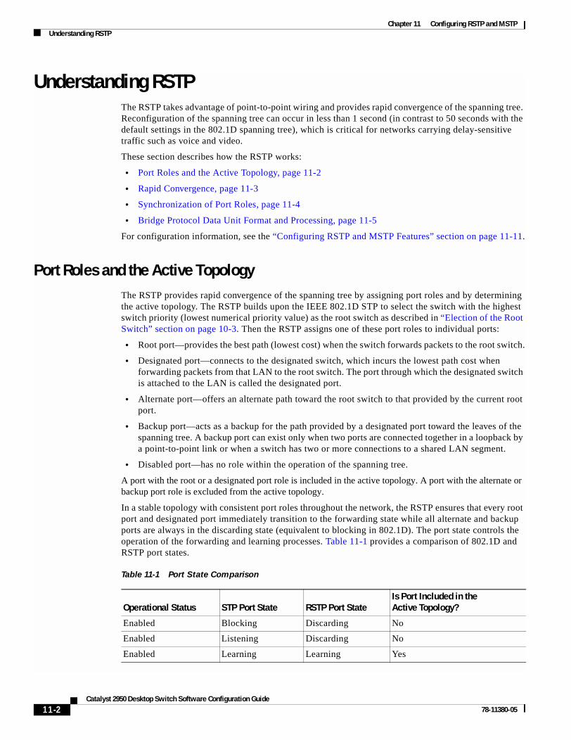
Chapter 11 Configuring RSTP and MSTPUnderstanding RSTP
Understanding RSTPThe RSTP takes advantage of point-to-point wiring and provides rapid convergence of the spanning tree. Reconfiguration of the spanning tree can occur in less than 1 second (in contrast to 50 seconds with the default settings in the 802.1D spanning tree), which is critical for networks carrying delay-sensitive traffic such as voice and video.
These section describes how the RSTP works:
• Port Roles and the Active Topology, page 11-2
• Rapid Convergence, page 11-3
• Synchronization of Port Roles, page 11-4
• Bridge Protocol Data Unit Format and Processing, page 11-5
For configuration information, see the “Configuring RSTP and MSTP Features” section on page 11-11.
Port Roles and the Active TopologyThe RSTP provides rapid convergence of the spanning tree by assigning port roles and by determining the active topology. The RSTP builds upon the IEEE 802.1D STP to select the switch with the highest switch priority (lowest numerical priority value) as the root switch as described in “Election of the Root Switch” section on page 10-3. Then the RSTP assigns one of these port roles to individual ports:
• Root port—provides the best path (lowest cost) when the switch forwards packets to the root switch.
• Designated port—connects to the designated switch, which incurs the lowest path cost when forwarding packets from that LAN to the root switch. The port through which the designated switch is attached to the LAN is called the designated port.
• Alternate port—offers an alternate path toward the root switch to that provided by the current root port.
• Backup port—acts as a backup for the path provided by a designated port toward the leaves of the spanning tree. A backup port can exist only when two ports are connected together in a loopback by a point-to-point link or when a switch has two or more connections to a shared LAN segment.
• Disabled port—has no role within the operation of the spanning tree.
A port with the root or a designated port role is included in the active topology. A port with the alternate or backup port role is excluded from the active topology.
In a stable topology with consistent port roles throughout the network, the RSTP ensures that every root port and designated port immediately transition to the forwarding state while all alternate and backup ports are always in the discarding state (equivalent to blocking in 802.1D). The port state controls the operation of the forwarding and learning processes. Table 11-1 provides a comparison of 802.1D and RSTP port states.
Table 11-1 Port State Comparison
Operational Status STP Port State RSTP Port StateIs Port Included in the Active Topology?
Enabled Blocking Discarding No
Enabled Listening Discarding No
Enabled Learning Learning Yes
11-2Catalyst 2950 Desktop Switch Software Configuration Guide
78-11380-05

Chapter 11 Configuring RSTP and MSTPUnderstanding RSTP
To be consistent with Cisco STP implementations, this guide documents the port state as blocking instead of discarding. Designated ports start in the listening state.
Rapid ConvergenceThe RSTP provides for rapid recovery of connectivity following the failure of switch, a switch port, or a LAN. It provides rapid convergence for edge ports, new root ports, and ports connected through point-to-point links as follows:
• Edge ports—If you configure a port as an edge port on an RSTP switch by using the spanning-tree portfast interface configuration command, the edge port immediately transitions to the forwarding state. An edge port is the same as a Port Fast-enabled port, and you should enable it only on ports that connect to a single end station.
• Root ports—If the RSTP selects a new root port, it blocks the old root port and immediately transitions the new root port to the forwarding state.
• Point-to-point links—If you connect a port to another port through a point-to-point link and the local port becomes a designated port, it negotiates a rapid transition with the other port by using the proposal-agreement handshake to ensure a loop-free topology.
As shown in Figure 11-1, Switch A is connected to Switch B through a point-to-point link, and all of the ports are in the blocking state. Assume that the priority of Switch A is a smaller numerical value than the priority of Switch B. Switch A sends a proposal message (a configuration bridge protocol data unit [BPDU] with the proposal flag set) to Switch B, proposing itself as the designated switch.
After receiving the proposal message, Switch B selects as its new root port the port from which the proposal message was received, forces all nonedge ports to the blocking state, and sends an agreement message (a BPDU with the agreement flag set) through its new root port.
After receiving Switch B’s agreement message, Switch A also immediately transitions its designated port to the forwarding state. No loops in the network are formed because Switch B blocked all of its nonedge ports and because there is a point-to-point link between Switches A and B.
When Switch C is connected to Switch B, a similar set of handshaking messages are exchanged. Switch C selects the port connected to Switch B as its root port, and both ends immediately transition to the forwarding state. With each iteration of this handshaking process, one more switch joins the active topology. As the network converges, this proposal-agreement handshaking progresses from the root toward the leaves of the spanning tree.
The switch determines the link type from the port duplex mode: a full-duplex port is considered to have a point-to-point connection; a half-duplex port is considered to have a shared connection. You can override the default setting that is determined by the duplex setting by using the spanning-tree link-type interface configuration command.
Enabled Forwarding Forwarding Yes
Disabled Disabled Discarding No
Table 11-1 Port State Comparison (continued)
Operational Status STP Port State RSTP Port StateIs Port Included in the Active Topology?
11-3Catalyst 2950 Desktop Switch Software Configuration Guide
78-11380-05

Chapter 11 Configuring RSTP and MSTPUnderstanding RSTP
Figure 11-1 Proposal and Agreement Handshaking for Rapid Convergence
Synchronization of Port RolesWhen the switch receives a proposal message on one of its ports and that port is selected as the new root port, the RSTP forces all other ports to synchronize with the new root information.
The switch is synchronized with superior root information received on the root port if all other ports are synchronized. An individual port on the switch is synchronized if
• That port is in the blocking state
• It is an edge port (a port configured to be at the edge of the network)
If a designated port is in the forwarding state and is not configured as an edge port, it transitions to the blocking state when the RSTP forces it to synchronize with new root information. In general, when the RSTP forces a port to synchronize with root information and the port does not satisfy any of the above conditions, its port state is set to blocking.
After ensuring all of the ports are synchronized, the switch sends an agreement message to the designated switch corresponding to its root port. When the switches connected by a point-to-point link are in agreement about their port roles, the RSTP immediately transitions the port states to forwarding. The sequence of events is shown in Figure 11-2.
ProposalSwitch A Switch B
FF
RPDP
FF
RPDP
FF
RPDP
FF
RPDP
Switch C
7400
7
AgreementRootDesignated
switch
RootDesignated
switch Proposal
RootDesignated
switch Agreement
DP = designated portRP = root portF = forwarding
11-4Catalyst 2950 Desktop Switch Software Configuration Guide
78-11380-05

Chapter 11 Configuring RSTP and MSTPUnderstanding RSTP
Figure 11-2 Sequence of Events During Rapid Convergence
Bridge Protocol Data Unit Format and ProcessingThe RSTP BPDU format is the same as the IEEE 802.1D BPDU format except that the protocol version is set to 2. A new one-byte version 1 Length field is set to zero, which means that no version 1 protocol information is present. Table 11-2 shows the RSTP flag fields.
The sending switch sets the proposal flag in the RSTP BPDU to propose itself as the designated switch on that LAN. The port role in the proposal message is always set to the designated port.
The sending switch sets the agreement flag in the RSTP BPDU to accept the previous proposal. The port role in the agreement message is always set to the root port.
2. Block9. Forward
1. Proposal4. Agreement
6. Proposal
Root portDesignated port
8. Agreement 10. Agreement
Edge port
7. Proposal
5. Forward
3. Block11. Forward
7400
8
Table 11-2 RSTP BPDU Flags
Bit Function
0 Topology change (TC)
1 Proposal
2–3:
00
01
10
11
Port role:
Unknown
Alternate port
Root port
Designated port
4 Learning
5 Forwarding
6 Agreement
7 Topology change acknowledgement (TCA)
11-5Catalyst 2950 Desktop Switch Software Configuration Guide
78-11380-05

Chapter 11 Configuring RSTP and MSTPUnderstanding RSTP
The RSTP does not have a separate topology change notification (TCN) BPDU. It uses the topology change (TC) flag to show the topology changes. However, for interoperability with 802.1D switches, the RSTP switch processes and generates TCN BPDUs.
The learning and forwarding flags are set according to the state of the sending port.
Processing Superior BPDU Information
If a port receives superior root information (lower bridge ID, lower path cost, and so forth) than currently stored for the port, the RSTP triggers a reconfiguration. If the port is proposed and is selected as the new root port, RSTP forces all the other ports to synchronize.
If the BPDU received is an RSTP BPDU with the proposal flag set, the switch sends an agreement message after all of the other ports are synchronized. If the BPDU is an 802.1D BPDU, the switch does not set the proposal flag and starts the forward-delay timer for the port. The new root port requires twice the forward-delay time to transition to the forwarding state.
If the superior information received on the port causes the port to become a backup or alternate port, RSTP sets the port to the blocking state but does not send the agreement message. The designated port continues sending BPDUs with the proposal flag set until the forward-delay timer expires, at which time the port transitions to the forwarding state.
Processing Inferior BPDU Information
If a designated port receives an inferior BPDU (higher bridge ID, higher path cost, and so forth than currently stored for the port) with a designated port role, it immediately replies with its own information.
Topology ChangesThis section describes the differences between the RSTP and the 802.1D in handling spanning-tree topology changes.
• Detection—Unlike 802.1D in which any transition between the blocking and the forwarding state causes a topology change, only transitions from the blocking to the forwarding state cause a topology change with RSTP (only an increase in connectivity is considered a topology change). State changes on an edge port do not cause a topology change. When an RSTP switch detects a topology change, it flushes the learned information on all of its nonedge ports.
• Notification—Unlike 802.1D, which uses TCN BPDUs, the RSTP does not use them. However, for 802.1D interoperability, an RSTP switch processes and generates TCN BPDUs.
• Acknowledgement—When an RSTP switch receives a TCN message on a designated port from an 802.1D switch, it replies with an 802.1D configuration BPDU with the TCA bit set. However, if the TC-while timer (the same as the topology-change timer in 802.1D) is active on a root port connected to an 802.1D switch and a configuration BPDU with the TCA bit set is received, the TC-while timer is reset.
This behavior is only required to support 802.1D switches. The RSTP BPDUs never have the TCA bit set.
11-6Catalyst 2950 Desktop Switch Software Configuration Guide
78-11380-05

Chapter 11 Configuring RSTP and MSTPUnderstanding MSTP
• Propagation—When an RSTP switch receives a TC message from another switch through a designated or root port, it propagates the topology change to all of its nonedge, edge, designated ports, and root port (excluding the port on which it is received). The switch starts the TC-while timer for all such ports and flushes the information learned on them.
• Protocol migration—For backward compatibility with 802.1D switches, RSTP selectively sends 802.1D configuration BPDUs and TCN BPDUs on a per-port basis.
When a port is initialized, the migrate-delay timer is started (specifies the minimum time during which RSTP BPDUs are sent), and RSTP BPDUs are sent. While this timer is active, the switch processes all BPDUs received on that port and ignores the protocol type.
If the switch receives an 802.1D BPDU after the port’s migration-delay timer has expired, it assumes that it is connected to an 802.1D switch and starts using only 802.1D BPDUs. However, if the RSTP switch is using 802.1D BPDUs on a port and receives an RSTP BPDU after the timer has expired, it restarts the timer and starts using RSTP BPDUs on that port.
Understanding MSTPMSTP, which uses RSTP for rapid convergence, enables VLANs to be grouped into a spanning-tree instance, with each instance having a spanning-tree topology independent of other spanning-tree instances. This architecture provides multiple forwarding paths for data traffic, enables load balancing, and reduces the number of spanning-tree instances required to support a large number of VLANs.
These sections describe how the MSTP works:
• Multiple Spanning-Tree Regions, page 11-7
• IST, CIST, and CST, page 11-8
• Hop Count, page 11-10
For configuration information, see the “Configuring RSTP and MSTP Features” section on page 11-11.
Multiple Spanning-Tree RegionsFor switches to participate in multiple spanning-tree (MST) instances, you must consistently configure the switches with the same MST configuration information. A collection of interconnected switches that have the same MST configuration comprises an MST region as shown in Figure 11-3 on page 11-9.
The MST configuration determines to which MST region each switch belongs. The configuration includes the name of the region, the revision number, and the MST instance-to-VLAN assignment map. You configure the switch for a region by using the spanning-tree mst configuration global configuration command, after which the switch enters the MST configuration mode. From this mode, you can map VLANs to an MST instance by using the instance MST configuration command, specify the region name by using the name MST configuration command, and set the revision number by using the revision MST configuration command.
A region can have one member or multiple members with the same MST configuration; each member must be capable of processing RSTP BPDUs. There is no limit to the number of MST regions in a network, but each region can support up to 16 spanning-tree instances. You can assign a VLAN to only one spanning-tree instance at a time.
11-7Catalyst 2950 Desktop Switch Software Configuration Guide
78-11380-05

Chapter 11 Configuring RSTP and MSTPUnderstanding MSTP
IST, CIST, and CSTUnlike PVST+ in which all the spanning-tree instances are independent, the MSTP establishes and maintains two types of spanning-trees:
• An internal spanning tree (IST), which is the spanning tree that runs in an MST region.
Within each MST region, the MSTP maintains multiple spanning-tree instances. Instance 0 is a special instance for a region, known as the internal spanning tree (IST). All other MST instances are numbered from 1 to 15.
The IST is the only spanning-tree instance that sends and receives BPDUs; all of the other spanning-tree instance information is contained in M-records, which are encapsulated within MSTP BPDUs. Because the MSTP BPDU carries information for all instances, the number of BPDUs that need to be processed by a switch to support multiple spanning-tree instances is significantly reduced.
All MST instances within the same region share the same protocol timers, but each MST instance has its own topology parameters, such as root switch ID, root path cost, and so forth. By default, all VLANs are assigned to the IST.
An MST instance is local to the region; for example, MST instance 1 in region A is independent of MST instance 1 in region B, even if regions A and B are interconnected.
• A common and internal spanning tree (CIST), which is a collection of the ISTs in each MST region, and the common spanning tree (CST) that interconnects the MST regions and single spanning trees.
The spanning tree computed in a region appears as a subtree in the CST that encompasses the entire switched domain. The CIST is formed as a result of the spanning-tree algorithm running between switches that support the 802.1W, 802.1S, and 802.1D protocols. The CIST inside an MST region is the same as the CST outside a region.
For more information, see the “Operations Within an MST Region” section on page 11-8 and the “Operations Between MST Regions” section on page 11-9.
Operations Within an MST Region
The IST connects all the MSTP switches in a region. When the IST converges, the root of the IST becomes the IST master (shown in Figure 11-3 on page 11-9), which is the switch within the region with the lowest bridge ID and path cost to the CST root. The IST master also is the CST root if there is only one region within the network. If the CST root is outside the region, one of the MSTP switches at the boundary of the region is selected as the IST master.
When an MSTP switch initializes, it sends BPDUs claiming itself as the root of the CST and the IST master, with both of the path costs to the CST root and to the IST master set to zero. The switch also initializes all of its MST instances and claims to be the root for all of them. If the switch receives superior MST root information (lower bridge ID, lower path cost, and so forth) than currently stored for the port, it relinquishes its claim as the IST master.
During initialization, a region might have many subregions, each with its own IST master. As switches receive superior IST information, they leave their old subregions and join the new subregion that might contain the true IST master. Thus all subregions shrink, except for the one that contains the true IST master.
For correct operation, all switches in the MST region must agree on the same IST master. Therefore, any two switches in the region synchronize their port roles for an MST instance only if they converge to a common IST master.
11-8Catalyst 2950 Desktop Switch Software Configuration Guide
78-11380-05

Chapter 11 Configuring RSTP and MSTPUnderstanding MSTP
Operations Between MST Regions
If there are multiple regions or legacy 802.1D switches within the network, MSTP establishes and maintains the CST, which includes all MST regions and all legacy STP switches in the network. The MST instances combine with the IST at the boundary of the region to become the CST.
The IST connects all the MSTP switches in the region and appears as a subtree in the CST that encompasses the entire switched domain, with the root of the subtree being the IST master. The MST region appears as a virtual switch to adjacent STP switches and MST regions.
Figure 11-3 shows a network with three MST regions and a legacy 802.1D switch (D). The IST master for region 1 (A) is also the CST root. The IST master for region 2 (B) and the IST master for region 3 (C) are the roots for their respective subtrees within the CST. The RSTP runs in all regions.
Figure 11-3 MST Regions, IST Masters, and the CST Root
Figure 11-3 does not show additional MST instances for each region. Note that the topology of MST instances can be different from that of the IST for the same region.
Only the CST instance sends and receives BPDUs, and MST instances add their spanning-tree information into the BPDUs to interact with neighboring switches and compute the final spanning-tree topology. Because of this, the spanning-tree parameters related to BPDU transmission (for example, hello time, forward time, max-age, and max-hops) are configured only on the CST instance but affect all MST instances. Parameters related to the spanning-tree topology (for example, switch priority, port VLAN cost, port VLAN priority) can be configured on both the CST instance and the MST instance.
MSTP switches use version 3 RSTP BPDUs or 802.1D STP BPDUs to communicate with legacy 802.1D switches. MSTP switches use MSTP BPDUs to communicate with MSTP switches.
IST masterand CST root
IST master IST master
A
MST Region 1
DLegacy 802.1D
B
MST Region 2 MST Region 3
C
7400
9
11-9Catalyst 2950 Desktop Switch Software Configuration Guide
78-11380-05

Chapter 11 Configuring RSTP and MSTPUnderstanding MSTP
Hop CountThe IST and MST instances do not use the message-age and maximum-age information in the configuration BPDU to compute the spanning-tree topology. Instead, they use the path cost to the root and a hop-count mechanism similar to the IP time-to-live (TTL) mechanism.
By using the spanning-tree mst max-hops global configuration command, you can configure the maximum hops inside the region and apply it to the IST and all MST instances in that region. The hop count achieves the same result as the message-age information (determines when to trigger a reconfiguration). The root switch of the instance always sends a BPDU (or M-record) with a cost of 0 and the hop count set to the maximum value. When a switch receives this BPDU, it decrements the received remaining hop count by one and propagates this value as the remaining hop count in the BPDUs it generates. When the count reaches zero, the switch discards the BPDU and ages the information held for the port.
The message-age and maximum-age information in the RSTP portion of the BPDU remain the same throughout the region, and the same values are propagated by the region’s designated ports at the boundary.
Boundary PortsA boundary port is a a port that connects an MST region to a single spanning-tree region running RSTP, or to a single spanning-tree region running 802.1D, or to another MST region with a different MST configuration. A boundary port also connects to a LAN, the designated switch of which is either a single spanning-tree switch or a switch with a different MST configuration.
At the boundary, the roles of the MST ports do not matter, and their state is forced to be the same as the IST port state (MST ports at the boundary are in the forwarding state only when the IST port is forwarding). An IST port at the boundary can have any port role except a backup port role.
On a shared boundary link, the MST ports wait in the blocking state for the forward-delay time to expire before transitioning to the learning state. The MST ports wait another forward-delay time before transitioning to the forwarding state.
If the boundary port is on a point-to-point link and it is the IST root port, the MST ports transition to the forwarding state as soon as the IST port transitions to the forwarding state.
If the IST port is a designated port on a point-to-point link and if the IST port transitions to the forwarding state because of an agreement received from its peer port, the MST ports also immediately transition to the forwarding state.
If a boundary port transitions to the forwarding state in an IST instance, it is forwarding in all MST instances, and a topology change is triggered. If a boundary port with the IST root or designated port role receives a topology change notice external to the MST cloud, the MSTP switch triggers a topology change in the IST instance and in all the MST instances active on that port.
11-10Catalyst 2950 Desktop Switch Software Configuration Guide
78-11380-05

Chapter 11 Configuring RSTP and MSTPInteroperability with 802.1D STP
Interoperability with 802.1D STPA switch running both MSTP and RSTP supports a built-in protocol migration mechanism that enables it to interoperate with legacy 802.1D switches. If this switch receives a legacy 802.1D configuration BPDU (a BPDU with the protocol version set to 0), it sends only 802.1D BPDUs on that port. An MST switch can also detect that a port is at the boundary of a region when it receives a legacy BPDU, an MST BPDU (version 3) associated with a different region, or an RST BPDU (version 2).
However, the switch does not automatically revert to the MSTP mode if it no longer receives 802.1D BPDUs because it cannot determine whether the legacy switch has been removed from the link unless the legacy switch is the designated switch. Also, a switch might continue to assign a boundary role to a port when the switch to which this switch is connected has joined the region. To restart the protocol migration process (force the renegotiation with neighboring switches), you can use the clear spanning-tree detected-protocols privileged EXEC command.
If all the legacy switches on the link are RSTP switches, they can process MSTP BPDUs as if they are RSTP BPDUs. Therefore, MSTP switches send either a version 0 configuration and TCN BPDUs or version 3 MSTP BPDUs on a boundary port. A boundary port connects to a LAN, the designated switch of which is either a single spanning-tree switch or a switch with a different MST configuration.
Configuring RSTP and MSTP FeaturesThese sections describe how to configure basic RSTP and MSTP features:
• Default RSTP and MSTP Configuration, page 11-12
• RSTP and MSTP Configuration Guidelines, page 11-12
• Specifying the MST Region Configuration and Enabling MSTP, page 11-13 (required)
• Configuring the Root Switch, page 11-14 (optional)
• Configuring a Secondary Root Switch, page 11-16 (optional)
• Configuring the Port Priority, page 11-17 (optional)
• Configuring the Path Cost, page 11-18 (optional)
• Configuring the Switch Priority, page 11-19 (optional)
• Configuring the Hello Time, page 11-19 (optional)
• Configuring the Forwarding-Delay Time, page 11-20 (optional)
• Configuring the Maximum-Aging Time, page 11-21 (optional)
• Configuring the Maximum-Hop Count, page 11-21 (optional)
• Specifying the Link Type to Ensure Rapid Transitions, page 11-22 (optional)
• Restarting the Protocol Migration Process, page 11-22 (optional)
11-11Catalyst 2950 Desktop Switch Software Configuration Guide
78-11380-05

Chapter 11 Configuring RSTP and MSTPConfiguring RSTP and MSTP Features
Default RSTP and MSTP ConfigurationTable 11-3 shows the default RSTP and MSTP configuration.
RSTP and MSTP Configuration GuidelinesThese are the configuration guidelines for RSTP and MSTP:
• The UplinkFast, BackboneFast, and cross-stack UplinkFast features are not supported with the RSTP and MSTP.
• Per-VLAN RSTP is not supported. When you enable MST by using the spanning-tree mode mst global configuration command, RSTP is enabled.
• PVST, PVST+ and MSTP are supported, but only one version can be active at any time; all VLANs run PVST, or all VLANs run MSTP.
• VTP propagation of the MST configuration is not supported. However, you can manually configure the MST configuration (region name, revision number, and VLAN-to-instance mapping) on each switch within the MST region by using the command-line interface (CLI) or through the SNMP support.
• For load balancing across redundant paths in the network to work, all VLAN-to-instance mapping assignments must match; otherwise, all traffic flows on a single link.
• All MST boundary ports must be forwarding for load balancing between a PVST+ and an MST cloud. For this to happen, the IST master of the MST cloud should also be the root of the CST. If the MST cloud consists of multiple MST regions, one of the MST regions must contain the CST root, and all of the other MST regions must have a better path to the root contained with the MST cloud than a path through the PVST+ cloud. You might have to manually configure the switches in the clouds.
• Partitioning the network into a large number of regions is not recommended. However, if this situation is unavoidable, we recommend that you partition the switched LAN into smaller LANs interconnected by routers or non-Layer 2 devices.
Table 11-3 Default RSTP and MSTP Configuration
Feature Default Setting
Spanning-tree mode PVST (MSTP and RSTP are disabled).
Switch priority (configurable on a per-CIST interface basis) 32768.
Spanning-tree port priority (configurable on a per-CIST interface basis) 128.
Spanning-tree port cost (configurable on a per-CIST interface basis) 1000 Mbps: 4.
100 Mbps: 19.
10 Mbps: 100.
Hello time 2 seconds.
Forward-delay time 15 seconds.
Maximum-aging time 20 seconds.
Maximum hop count 20 hops.
11-12Catalyst 2950 Desktop Switch Software Configuration Guide
78-11380-05

Chapter 11 Configuring RSTP and MSTPConfiguring RSTP and MSTP Features
Specifying the MST Region Configuration and Enabling MSTPFor two or more switches to be in the same MST region, they must have the same VLAN-to-instance mapping, the same configuration revision number, and the same name.
A region can have one member or multiple members with the same MST configuration; each member must be capable of processing RSTP BPDUs. There is no limit to the number of MST regions in a network, but each region can support up to 16 spanning-tree instances. You can assign a VLAN to only one spanning-tree instance at a time.
Beginning in privileged EXEC mode, follow these steps to specify the MST region configuration and enable MSTP. This procedure is required.
To return to the default MST region configuration, use the no spanning-tree mst configuration global configuration command. To return to the default VLAN-to-instance map, use the no instance instance-id [vlan vlan-range] MST configuration command. To return to the default name, use the no name MST
Command Purpose
Step 1 configure terminal Enter global configuration mode.
Step 2 spanning-tree mst configuration Enter MST configuration mode.
Step 3 instance instance-id vlan vlan-range Map VLANs to an MST instance.
• For instance-id, the range is 1 to 15.
• For vlan vlan-range, the range is 1 to 4094.
When you map VLANs to an MST instance, the mapping is incremental, and the range of VLANs specified is added or removed to the existing ones.
To specify a range, use a hyphen; for example, instance 1 vlan 1-63 maps VLANs 1 through 63 to MST instance 1.
To specify a series, use a comma; for example, instance 1 vlan 10, 20, 30 maps VLANs 10, 20, and 30 to MST instance 1.
Step 4 name name Specify the configuration name. The name string has a maximum length of 32 characters and is case sensitive.
Step 5 revision version Specify the configuration revision number. The range is 0 to 65535.
Step 6 show pending Verify your configuration by displaying the pending configuration.
Step 7 exit Apply all changes, and return to global configuration mode.
Step 8 spanning-tree mode mst Enable MSTP. RSTP is also enabled.
Caution Changing spanning-tree modes can disrupt traffic because all spanning-tree instances are stopped for the previous mode and restarted in the new mode.
You cannot run both MSTP and PVST at the same time.
Step 9 end Return to privileged EXEC mode.
Step 10 show running-config Verify your entries.
Step 11 copy running-config startup-config (Optional) Save your entries in the configuration file.
11-13Catalyst 2950 Desktop Switch Software Configuration Guide
78-11380-05

Chapter 11 Configuring RSTP and MSTPConfiguring RSTP and MSTP Features
configuration command. To return to the default revision number, use the no revision MST configuration command.To re-enable PVST, use the no spanning-tree mode or the spanning-tree mode pvst global configuration command.
This example shows how to enter MST configuration mode, map VLANs 10 to 20 to MST instance 1, name the region region1, set the configuration revision to 1, display the pending configuration, apply the changes, and return to global configuration mode:
Switch(config)# spanning-tree mst configurationSwitch(config-mst)# instance 1 vlan 10-20Switch(config-mst)# name region1Switch(config-mst)# revision 1Switch(config-mst)# show pendingPending MST configurationName [region1]Revision 1Instance Vlans Mapped-------- ---------------------0 1-9,21-40941 10-20-------------------------------
Switch(config-mst)# exitSwitch(config)#
Configuring the Root SwitchThe switch maintains a spanning-tree instance for the group of VLANs mapped to it. A bridge ID, consisting of the switch priority and the switch MAC address, is associated with each instance. The switch with the lowest bridge ID becomes the root switch for the group of VLANs.
To configure a switch to become the root, use the spanning-tree mst instance-id root global configuration command to modify the switch priority from the default value (32768) to a significantly lower value so that the switch becomes the root switch for the specified spanning-tree instance. When you enter this command, the switch checks the switch priorities of the root switches. Because of the extended system ID support, the switch sets its own priority for the specified instance to 24576 if this value will cause this switch to become the root for the specified spanning-tree instance.
If any root switch for the specified instance has a switch priority lower than 24576, the switch sets its own priority to 4096 less than the lowest switch priority. (4096 is the value of the least-significant bit of a 4-bit switch priority value as shown in Table 10-1 on page 10-4.)
Note Catalyst 2950 switches running software earlier than Release 12.1(9)EA1 do not support the extended system ID. Catalyst 2950 switches running software earlier than Release 12.1(9)EA1 do not support the MSTP.
Note If your network consists of switches that both do and do not support the extended system ID, it is unlikely that the switch with the extended system ID support will become the root switch. The extended system ID increases the switch priority value every time the VLAN number is greater than the priority of the connected switches running older software.
11-14Catalyst 2950 Desktop Switch Software Configuration Guide
78-11380-05

Chapter 11 Configuring RSTP and MSTPConfiguring RSTP and MSTP Features
Note The root switch for each spanning-tree instance should be a backbone or distribution switch. Do not configure an access switch as the spanning-tree primary root.
Use the diameter keyword, which is available only for MST instance 0, to specify the Layer 2 network diameter (that is, the maximum number of switch hops between any two end stations in the Layer 2 network). When you specify the network diameter, the switch automatically sets an optimal hello time, forward-delay time, and maximum-age time for a network of that diameter, which can significantly reduce the convergence time. You can use the hello keyword to override the automatically calculated hello time.
Note We recommend that you avoid manually configuring the hello time, forward-delay time, and maximum-age time by using the spanning-tree mst hello-time, spanning-tree mst forward-time, and the spanning-tree mst max-age global configuration commands after configuring the switch as the root switch.
Beginning in privileged EXEC mode, follow these steps to configure a switch as the root switch:
To return the switch to its default setting, use the no spanning-tree mst instance-id root global configuration command.
Command Purpose
Step 1 configure terminal Enter global configuration mode.
Step 2 spanning-tree mst instance-id root primary [diameter net-diameter [hello-time seconds]]
Configure a switch as the root switch.
• For instance-id, the range is 0 to 15.
• (Optional) For diameter net-diameter, specify the maximum number of switches between any two end stations. The range is 2 to 7. This keyword is available only for MST instance 0.
• (Optional) For hello-time seconds, specify the interval in seconds between the generation of configuration messages by the root switch. The range is 1 to 10 seconds; the default is 2 seconds.
Step 3 end Return to privileged EXEC mode.
Step 4 show spanning-tree mst instance-id Verify your entries.
Step 5 copy running-config startup-config (Optional) Save your entries in the configuration file.
11-15Catalyst 2950 Desktop Switch Software Configuration Guide
78-11380-05

Chapter 11 Configuring RSTP and MSTPConfiguring RSTP and MSTP Features
Configuring a Secondary Root SwitchWhen you configure a Catalyst 2950 switch that supports the extended system ID as the secondary root, the spanning-tree switch priority is modified from the default value (32768) to 28672. The switch is then likely to become the root switch for the specified instance if the primary root switch fails. This is assuming that the other network switches use the default switch priority of 32768 and therefore are unlikely to become the root switch. For Catalyst 2950 switches without the extended system ID support (software earlier than Release 12.1(9)EA1), the switch priority is changed to 16384.
You can execute this command on more than one switch to configure multiple backup root switches. Use the same network diameter and hello-time values that you used when you configured the primary root switch with the spanning-tree mst instance-id root primary global configuration command.
Beginning in privileged EXEC mode, follow these steps to configure a switch as the secondary root switch:
To return the switch to its default setting, use the no spanning-tree mst instance-id root global configuration command.
Command Purpose
Step 1 configure terminal Enter global configuration mode.
Step 2 spanning-tree mst instance-id root secondary [diameter net-diameter [hello-time seconds]]
Configure a switch as the secondary root switch.
• For instance-id, the range is 0 to 15.
• (Optional) For diameter net-diameter, specify the maximum number of switches between any two end stations. The range is 2 to 7. This keyword is available only for MST instance 0.
• (Optional) For hello-time seconds, specify the interval in seconds between the generation of configuration messages by the root switch. The range is 1 to 10 seconds; the default is 2 seconds.
Use the same network diameter and hello-time values that you used when configuring the primary root switch. See the “Configuring the Root Switch” section on page 11-14.
Step 3 end Return to privileged EXEC mode.
Step 4 show spanning-tree mst instance-id Verify your entries.
Step 5 copy running-config startup-config (Optional) Save your entries in the configuration file.
11-16Catalyst 2950 Desktop Switch Software Configuration Guide
78-11380-05

Chapter 11 Configuring RSTP and MSTPConfiguring RSTP and MSTP Features
Configuring the Port PriorityIf a loop occurs, the MSTP uses the port priority when selecting an interface to put into the forwarding state. You can assign higher priority values (lower numerical values) to interfaces that you want selected first and lower priority values (higher numerical values) that you want selected last. If all interfaces have the same priority value, the MSTP puts the interface with the lowest interface number in the forwarding state and blocks the other interfaces.
Beginning in privileged EXEC mode, follow these steps to configure the MSTP port priority of an interface:
Note The show spanning-tree mst interface interface-id privileged EXEC command displays information only if the port is in a link-up operative state. Otherwise, you can use the show running-config interface privileged EXEC command to confirm the configuration.
To return the interface to its default setting, use the no spanning-tree mst instance-id port-priority interface configuration command.
Command Purpose
Step 1 configure terminal Enter global configuration mode.
Step 2 interface interface-id Enter interface configuration mode, and specify an interface to configure.
Valid interfaces include physical ports and port channels. Valid port-channel numbers are 1 to 6.
Step 3 spanning-tree mst instance-id port-priority priority Configure the port priority for an MST instance.
• For instance-id, the range is 0 to 15.
• For priority, the range is 0 to 255; the default is 128. The lower the number, the higher the priority.
Step 4 end Return to privileged EXEC mode.
Step 5 show spanning-tree mst interface interface-id
or
show spanning-tree mst instance-id
Verify your entries.
Step 6 copy running-config startup-config (Optional) Save your entries in the configuration file.
11-17Catalyst 2950 Desktop Switch Software Configuration Guide
78-11380-05

Chapter 11 Configuring RSTP and MSTPConfiguring RSTP and MSTP Features
Configuring the Path CostThe MSTP path cost default value is derived from the media speed of an interface. If a loop occurs, the MSTP uses cost when selecting an interface to put in the forwarding state. You can assign lower cost values to interfaces that you want selected first and higher cost values that you want selected last. If all interfaces have the same cost value, the MSTP puts the interface with the lowest interface number in the forwarding state and blocks the other interfaces.
Beginning in privileged EXEC mode, follow these steps to configure the MSTP cost of an interface:
Note The show spanning-tree mst interface interface-id privileged EXEC command displays information only for ports that are in a link-up operative state. Otherwise, you can use the show running-config privileged EXEC command to confirm the configuration.
To return the interface to its default setting, use the no spanning-tree mst instance-id cost interface configuration command.
Command Purpose
Step 1 configure terminal Enter global configuration mode.
Step 2 interface interface-id Enter interface configuration mode, and specify an interface to configure. Valid interfaces include physical ports and port channels. Valid port-channel numbers are 1 to 6.
Step 3 spanning-tree mst instance-id cost cost Configure the cost for an MST instance.
If a loop occurs, the MSTP uses the path cost when selecting an interface to place into the forwarding state. A lower path cost represents higher-speed transmission.
• For instance-id, the range is 0 to 15.
• For cost, the range is 1 to 200000000; the default value is derived from the media speed of the interface.
Step 4 end Return to privileged EXEC mode.
Step 5 show spanning-tree mst interface interface-id
or
show spanning-tree mst instance-id
Verify your entries.
Step 6 copy running-config startup-config (Optional) Save your entries in the configuration file.
11-18Catalyst 2950 Desktop Switch Software Configuration Guide
78-11380-05

Chapter 11 Configuring RSTP and MSTPConfiguring RSTP and MSTP Features
Configuring the Switch PriorityYou can configure the switch priority and make it more likely that the switch will be chosen as the root switch.
Note Exercise care when using this command. For most situations, we recommend that you use the spanning-tree mst instance-id root primary and the spanning-tree mst instance-id root secondary global configuration commands to modify the switch priority.
Beginning in privileged EXEC mode, follow these steps to configure the switch priority:
To return the switch to its default setting, use the no spanning-tree mst instance-id priority global configuration command.
Configuring the Hello TimeYou can configure the interval between the generation of configuration messages by the root switch by changing the hello time.
Note Exercise care when using this command. For most situations, we recommend that you use the spanning-tree mst instance-id root primary and the spanning-tree mst instance-id root secondary global configuration commands to modify the hello time.
Command Purpose
Step 1 configure terminal Enter global configuration mode.
Step 2 spanning-tree mst instance-id priority priority Configure the switch priority for an MST instance.
• For instance-id, the range is 0 to 15.
• For priority, the range is 0 to 61440 in increments of 4096; the default is 32768. The lower the number, the more likely the switch will be chosen as the root switch.
Valid priority values are 0, 4096, 8192, 12288, 16384, 20480, 24576, 28672, 32768, 36864, 40960, 45056, 49152, 53248, 57344, and 61440. All other values are rejected.
Step 3 end Return to privileged EXEC mode.
Step 4 show spanning-tree mst instance-id Verify your entries.
Step 5 copy running-config startup-config (Optional) Save your entries in the configuration file.
11-19Catalyst 2950 Desktop Switch Software Configuration Guide
78-11380-05

Chapter 11 Configuring RSTP and MSTPConfiguring RSTP and MSTP Features
Beginning in privileged EXEC mode, follow these steps to configure the hello time for all MST instances:
To return the switch to its default setting, use the no spanning-tree mst hello-time global configuration command.
Configuring the Forwarding-Delay TimeBeginning in privileged EXEC mode, follow these steps to configure the forwarding-delay time for all MST instances:
To return the switch to its default setting, use the no spanning-tree mst forward-time global configuration command.
Command Purpose
Step 1 configure terminal Enter global configuration mode.
Step 2 spanning-tree mst hello-time seconds Configure the hello time for all MST instances. The hello time is the interval between the generation of configuration messages by the root switch. These messages mean that the switch is alive.
For seconds, the range is 1 to 10; the default is 2.
Step 3 end Return to privileged EXEC mode.
Step 4 show spanning-tree mst Verify your entries.
Step 5 copy running-config startup-config (Optional) Save your entries in the configuration file.
Command Purpose
Step 1 configure terminal Enter global configuration mode.
Step 2 spanning-tree mst forward-time seconds Configure the forward time for all MST instances. The forward delay is the number of seconds a port waits before changing from its spanning-tree learning and listening states to the forwarding state.
For seconds, the range is 4 to 30; the default is 15.
Step 3 end Return to privileged EXEC mode.
Step 4 show spanning-tree mst Verify your entries.
Step 5 copy running-config startup-config (Optional) Save your entries in the configuration file.
11-20Catalyst 2950 Desktop Switch Software Configuration Guide
78-11380-05

Chapter 11 Configuring RSTP and MSTPConfiguring RSTP and MSTP Features
Configuring the Maximum-Aging TimeBeginning in privileged EXEC mode, follow these steps to configure the maximum-aging time for all MST instances:
To return the switch to its default setting, use the no spanning-tree mst max-age global configuration command.
Configuring the Maximum-Hop CountBeginning in privileged EXEC mode, follow these steps to configure the maximum-hop count for all MST instances:
To return the switch to its default setting, use the no spanning-tree mst max-hops global configuration command.
Command Purpose
Step 1 configure terminal Enter global configuration mode.
Step 2 spanning-tree mst max-age seconds Configure the maximum-aging time for all MST instances. The maximum-aging time is the number of seconds a switch waits without receiving spanning-tree configuration messages before attempting a reconfiguration.
For seconds, the range is 6 to 40; the default is 20.
Step 3 end Return to privileged EXEC mode.
Step 4 show spanning-tree mst Verify your entries.
Step 5 copy running-config startup-config (Optional) Save your entries in the configuration file.
Command Purpose
Step 1 configure terminal Enter global configuration mode.
Step 2 spanning-tree mst max-hops hop-count Specify the number of hops in a region before the BPDU is discarded, and the information held for a port is aged.
For hop-count, the range is 1 to 40; the default is 20.
Step 3 end Return to privileged EXEC mode.
Step 4 show spanning-tree mst Verify your entries.
Step 5 copy running-config startup-config (Optional) Save your entries in the configuration file.
11-21Catalyst 2950 Desktop Switch Software Configuration Guide
78-11380-05

Chapter 11 Configuring RSTP and MSTPConfiguring RSTP and MSTP Features
Specifying the Link Type to Ensure Rapid TransitionsIf you connect a port to another port through a point-to-point link and the local port becomes a designated port, the RSTP negotiates a rapid transition with the other port by using the proposal-agreement handshake to ensure a loop-free topology as described in the “Rapid Convergence” section on page 11-3.
By default, the link type is determined from the duplex mode of the interface: a full-duplex port is considered to have a point-to-point connection; a half-duplex port is considered to have a shared connection. If you have a half-duplex link physically connected point-to-point to a single port on a remote switch running RSTP, you can override the default setting of the link type and enable rapid transitions to the forwarding state.
Beginning in privileged EXEC mode, follow these steps to override the default link-type setting:
To return the switch to its default setting, use the no spanning-tree link-type interface configuration command.
Restarting the Protocol Migration ProcessA switch running both MSTP and RSTP supports a built-in protocol migration mechanism that enables it to interoperate with legacy 802.1D switches. If this switch receives a legacy 802.1D configuration BPDU (a BPDU with the protocol version set to 0), it sends only 802.1D BPDUs on that port. An MSTP switch can also detect that a port is at the boundary of a region when it receives a legacy BPDU, an MST BPDU (version 3) associated with a different region, or an RST BPDU (version 2).
However, the switch does not automatically revert to the MSTP mode if it no longer receives 802.1D BPDUs because it cannot determine whether the legacy switch has been removed from the link unless the legacy switch is the designated switch. A switch also might continue to assign a boundary role to a port when the switch to which it is connected has joined the region.
To restart the protocol migration process (force the renegotiation with neighboring switches) on the entire switch, you can use the clear spanning-tree detected-protocols privileged EXEC command. Use the clear spanning-tree detected-protocols interface interface-id privileged EXEC command to restart the protocol migration process on a specific interface.
Command Purpose
Step 1 configure terminal Enter global configuration mode.
Step 1 interface interface-id Enter interface configuration mode, and specify the interface to configure. Valid interfaces include physical ports, VLANs, and port channels. Valid VLAN IDs are 1 to 4094; valid port-channel numbers are 1 to 6.
Step 2 spanning-tree link-type point-to-point Specify that the link type of a port is point-to-point.
Step 3 end Return to privileged EXEC mode.
Step 4 show spanning-tree mst interface interface-id Verify your entries.
Step 5 copy running-config startup-config (Optional) Save your entries in the configuration file.
11-22Catalyst 2950 Desktop Switch Software Configuration Guide
78-11380-05

Chapter 11 Configuring RSTP and MSTPDisplaying the MST Configuration and Status
Displaying the MST Configuration and StatusTo display the spanning-tree status, use one or more of the privileged EXEC commands in Table 11-4:
For information about other keywords for the show spanning-tree privileged EXEC command, refer to the command reference for this release.
Table 11-4 Commands for Displaying MST Status
Command Purpose
show spanning-tree mst configuration Displays the MST region configuration.
show spanning-tree mst instance-id Displays MST information for the specified instance.
show spanning-tree mst interface interface-id Displays MST information for the specified interface. Valid interfaces include physical ports, VLANs, and port channels. The valid VLAN range is 1 to 4094; the valid port-channel range is 1 to 6.
11-23Catalyst 2950 Desktop Switch Software Configuration Guide
78-11380-05

Chapter 11 Configuring RSTP and MSTPDisplaying the MST Configuration and Status
11-24Catalyst 2950 Desktop Switch Software Configuration Guide
78-11380-05

Catalyst 2950 Deskto78-11380-05
C H A P T E R 12
Configuring Optional Spanning-Tree FeaturesThis chapter describes how to configure optional spanning-tree features. You can configure all of these features when your switch is running the per-VLAN spanning-tree (PVST). You can only configure the noted features when your switch is running the Multiple Spanning Tree Protocol (MSTP). To use these features with MSTP, you must have the enhanced software image (EI) installed on your switch.
For information on configuring the Spanning Tree Protocol (STP), see Chapter 10, “Configuring STP.” For information on configuring the Rapid Spanning Tree Protocol (RSTP) and the Multiple Spanning Tree Protocol (MSTP), see Chapter 11, “Configuring RSTP and MSTP.”
Note For complete syntax and usage information for the commands used in this chapter, refer to the command reference for this release.
This chapter consists of these sections:
• Understanding Optional Spanning-Tree Features, page 12-1
• Configuring Optional Spanning-Tree Features, page 12-13
• Displaying the Spanning-Tree Status, page 12-21
Understanding Optional Spanning-Tree FeaturesThese sections describe how the optional spanning-tree features work:
• Understanding Port Fast, page 12-2
• Understanding BPDU Guard, page 12-3
• Understanding BPDU Filtering, page 12-3
• Understanding UplinkFast, page 12-4
• Understanding Cross-Stack UplinkFast, page 12-5
• Understanding BackboneFast, page 12-10
• Understanding Root Guard, page 12-12
• Understanding Loop Guard, page 12-13
12-1p Switch Software Configuration Guide

Chapter 12 Configuring Optional Spanning-Tree FeaturesUnderstanding Optional Spanning-Tree Features
Understanding Port FastPort Fast immediately brings an interface configured as an access or trunk port to the forwarding state from a blocking state, bypassing the listening and learning states. You can use Port Fast on ports connected to a single workstation or server, as shown in Figure 12-1, to allow those devices to immediately connect to the network, rather than waiting for the spanning tree to converge.
Ports connected to a single workstation or server should not receive bridge protocol data units (BPDUs). A port with Port Fast enabled goes through the normal cycle of spanning-tree status changes when the switch is restarted.
Note Because the purpose of Port Fast is to minimize the time ports must wait for spanning-tree to converge, it is effective only when used on ports connected to end stations. If you enable Port Fast on a port connecting to another switch, you risk creating a spanning-tree loop.
If your switch is running PVST or MSTP, you can enable this feature by using the spanning-tree portfast interface configuration or the spanning-tree portfast default global configuration command. The MSTP is available only if you have the EI installed on your switch.
Figure 12-1 Port Fast-Enabled Ports
Catalyst 6000series switch
Catalyst 3550switch
Catalyst 2950 or 3550switch
WorkstationsWorkstations
Server
PortFast-enabled portPort
Fast-enabledports
Catalyst 2950 or 3550switch
7462
2
12-2Catalyst 2950 Desktop Switch Software Configuration Guide
78-11380-05

Chapter 12 Configuring Optional Spanning-Tree FeaturesUnderstanding Optional Spanning-Tree Features
Understanding BPDU GuardThe BPDU guard feature can be globally enabled on the switch or can be enabled per interface, but the feature operates with some differences.
At the global level, you can enable BPDU guard on Port Fast-enabled ports by using the spanning-tree portfast bpduguard default global configuration command. Spanning tree shuts down ports that are in a Port Fast-operational state. In a valid configuration, Port Fast-enabled ports do not receive BPDUs. Receiving a BPDU on a Port Fast-enabled port signals an invalid configuration, such as the connection of an unauthorized device, and the BPDU guard feature puts the port in the error-disabled state.
At the interface level, you can enable BPDU guard on any port by using the spanning-tree bpduguard enable interface configuration command without also enabling the Port Fast feature. When the port receives a BPDU, it is put in the error-disabled state.
The BPDU guard feature provides a secure response to invalid configurations because you must manually put the port back in service. Use the BPDU guard feature in a service-provider network to prevent an access port from participating in the spanning tree.
If your switch is running PVST or MSTP, you can enable the BPDU guard feature for the entire switch or for an interface.The MSTP is available only if you have the EI installed on your switch.
Understanding BPDU FilteringThe BPDU filtering feature can be globally enabled on the switch or can be enabled per interface, but the feature operates with some differences.
At the global level, you can enable BPDU filtering on Port Fast-enabled ports by using the spanning-tree portfast bpdufilter default global configuration command. This command prevents ports that are in a Port Fast-operational state from sending or receiving BPDUs. The ports still send a few BPDUs at link-up before the switch begins to filter outbound BPDUs. You should globally enable BPDU filtering on a switch so that hosts connected to these ports do not receive BPDUs. If a BPDU is received on a Port Fast-enabled port, the port loses its Port Fast-operational status, and BPDU filtering is disabled.
At the interface level, you can enable BPDU filtering on any port without also enabling the Port Fast feature by using the spanning-tree bpdufilter enable interface configuration command. This command prevents the port from sending or receiving BPDUs.
Caution Enabling BPDU filtering on an interface is the same as disabling spanning tree on it and can result in spanning-tree loops.
If your switch is running PVST or MSTP, you can enable the BPDU filtering feature for the entire switch or for an interface.The MSTP is available only if you have the EI installed on your switch.
12-3Catalyst 2950 Desktop Switch Software Configuration Guide
78-11380-05

Chapter 12 Configuring Optional Spanning-Tree FeaturesUnderstanding Optional Spanning-Tree Features
Understanding UplinkFastSwitches in hierarchical networks can be grouped into backbone switches, distribution switches, and access switches. Figure 12-2 shows a complex network where distribution switches and access switches each have at least one redundant link that spanning tree blocks to prevent loops.
Figure 12-2 Switches in a Hierarchical Network
If a switch looses connectivity, it begins using the alternate paths as soon as the spanning tree selects a new root port. By enabling UplinkFast with the spanning-tree uplinkfast global configuration command, you can accelerate the choice of a new root port when a link or switch fails or when the spanning tree reconfigures itself. The root port transitions to the forwarding state immediately without going through the listening and learning states, as it would with the normal spanning-tree procedures. The UplinkFast feature is supported only when the switch is running PVST.
When the spanning tree reconfigures the new root port, other interfaces flood the network with multicast packets, one for each address that was learned on the interface. You can limit these bursts of multicast traffic by reducing the max-update-rate parameter (the default for this parameter is 150 packets per second). However, if you enter zero, station-learning frames are not generated, so the spanning-tree topology converges more slowly after a loss of connectivity.
Note UplinkFast is most useful in wiring-closet switches at the access or edge of the network. It is not appropriate for backbone devices. This feature might not be useful for other types of applications.
UplinkFast provides fast convergence after a direct link failure and achieves load balancing between redundant Layer 2 links using uplink groups. An uplink group is a set of Layer 2 interfaces (per VLAN), only one of which is forwarding at any given time. Specifically, an uplink group consists of the root port (which is forwarding) and a set of blocked ports, except for self-looping ports. The uplink group provides an alternate path in case the currently forwarding link fails.
Figure 12-3 shows an example topology with no link failures. Switch A, the root switch, is connected directly to Switch B over link L1 and to Switch C over link L2. The Layer 2 interface on Switch C that is connected directly to Switch B is in a blocking state.
2950 2950 2950 2950
Active linkBlocked link
Root bridge
Backbone switches
Distribution switches
Access switches
7462
3
Catalyst 3550switches
Catalyst 3550switches
12-4Catalyst 2950 Desktop Switch Software Configuration Guide
78-11380-05

Chapter 12 Configuring Optional Spanning-Tree FeaturesUnderstanding Optional Spanning-Tree Features
Figure 12-3 UplinkFast Example Before Direct Link Failure
If Switch C detects a link failure on the currently active link L2 on the root port (a direct link failure), UplinkFast unblocks the blocked port on Switch C and transitions it to the forwarding state without going through the listening and learning states, as shown in Figure 12-4. This change takes approximately 1 to 5 seconds.
Figure 12-4 UplinkFast Example After Direct Link Failure
Understanding Cross-Stack UplinkFastCross-stack UplinkFast (CSUF) provides a fast spanning-tree transition (fast convergence in less than 1 second under normal network conditions) across a stack of switches that use the GigaStack GBICs connected in a shared cascaded configuration (multidrop backbone). During the fast transition, an alternate redundant link on the stack of switches is placed in the forwarding state without causing temporary spanning-tree loops or loss of connectivity to the backbone. With this feature, you can have a redundant and resilient network in some configurations. You enable CSUF by using the spanning-tree stack-port interface configuration command. The CSUF feature is supported only when the switch is running PVST.
CSUF might not provide a fast transition all the time; in these cases, the normal spanning-tree transition occurs, completing in 30 to 40 seconds. For more information, see the “Events That Cause Fast Convergence” section on page 12-7.
L1
L2 L3
Switch C
Switch A(Root) Switch B
Blocked port
4357
5
L1
L2 L3
Switch C
Switch A(Root) Switch B
UplinkFast transitions portdirectly to forwarding state.
Link failure43
576
12-5Catalyst 2950 Desktop Switch Software Configuration Guide
78-11380-05

Chapter 12 Configuring Optional Spanning-Tree FeaturesUnderstanding Optional Spanning-Tree Features
How CSUF Works
CSUF ensures that one link in the stack is elected as the path to the root. As shown in Figure 12-5, Switches A, B, and C are cascaded through the GigaStack GBIC to form a multidrop backbone, which communicates control and data traffic across the switches at the access layer. The switches in the stack use their stack ports to communicate with each other and to connect to the stack backbone; stack ports are always in the spanning-tree forwarding state. The stack-root port on Switch A provides the path to the root of the spanning tree; the alternate stack-root ports on Switches B and C can provide an alternate path to the spanning-tree root if the current stack-root switch fails or if its link to the spanning-tree root fails.
Link A, the root link, is in the spanning-tree forwarding state; Links B and C are alternate redundant links that are in the spanning-tree blocking state. If Switch A fails, if its stack-root port fails, or if Link A fails, CSUF selects either the Switch B or Switch C alternate stack-root port and puts it into the forwarding state in less than 1 second.
Figure 12-5 Cross-Stack UplinkFast Topology
CSUF uses the Stack Membership Discovery Protocol to build a neighbor list of stack members through the receipt of discovery hello packets. When certain link loss or spanning-tree events occur (described in “Events That Cause Fast Convergence” section on page 12-7), the Fast Uplink Transition Protocol uses the neighbor list to send fast-transition requests on the stack port to stack members.
Switch A
Spanning-tree root
Backbone
Multidrop backbone(GigaStack GBIC connections)
Stack port
4906
7
Switch B Stack port
Forward
Link A(Root link)
Link B(Alternateredundantlink)
Link C(Alternateredundantlink)
100 or 1000 Mbps 100 or 1000 Mbps 100 or 1000 Mbps
ForwardForward
Switch C Stack port
Stack-root portAlternate stack-root port
Alternate stack-root port
12-6Catalyst 2950 Desktop Switch Software Configuration Guide
78-11380-05

Chapter 12 Configuring Optional Spanning-Tree FeaturesUnderstanding Optional Spanning-Tree Features
The switch sending the fast-transition request needs to do a fast transition to the forwarding state of a port that it has chosen as the root port, and it must obtain an acknowledgement from each stack switch before performing the fast transition.
Each switch in the stack determines if the sending switch is a better choice than itself to be the stack root of this spanning-tree instance by comparing the root, cost, and bridge ID. If the sending switch is the best choice as the stack root, each switch in the stack returns an acknowledgement; otherwise, it does not respond to the sending switch (drops the packet). The sending switch then has not received acknowledgements from all stack switches.
When acknowledgements are received from all stack switches, the Fast Uplink Transition Protocol on the sending switch immediately transitions its alternate stack-root port to the forwarding state. If acknowledgements from all stack switches are not obtained by the sending switch, the normal spanning-tree transitions (blocking, listening, learning, and forwarding) take place, and the spanning-tree topology converges at its normal rate (2 * forward-delay time + max-age time).
The Fast Uplink Transition Protocol is implemented on a per-VLAN basis and affects only one spanning-tree instance at a time.
Events That Cause Fast Convergence
Depending on the network event or failure, the CSUF fast convergence might or might not occur.
Fast convergence (less than 1 second under normal network conditions) occurs under these circumstances:
• The stack-root port link fails.
If two switches in the stack have alternate paths to the root, only one of the switches performs the fast transition.
• The failed link, which connects the stack root to the spanning-tree root, recovers.
• A network reconfiguration causes a new stack-root switch to be selected.
• A network reconfiguration causes a new port on the current stack-root switch to be chosen as the stack-root port.
Note The fast transition might not occur if multiple events occur simultaneously. For example, if a stack member switch is powered off, and at the same time, the link connecting the stack root to the spanning-tree root comes back up, the normal spanning-tree convergence occurs.
Normal spanning-tree convergence (30 to 40 seconds) occurs under these conditions:
• The stack-root switch is powered off, or the software failed.
• The stack-root switch, which was powered off or failed, is powered on.
• A new switch, which might become the stack root, is added to the stack.
• A switch other than the stack root is powered off or failed.
• A link fails between stack ports on the multidrop backbone.
12-7Catalyst 2950 Desktop Switch Software Configuration Guide
78-11380-05

Chapter 12 Configuring Optional Spanning-Tree FeaturesUnderstanding Optional Spanning-Tree Features
Limitations
These limitations apply to CSUF:
• CSUF uses the GigaStack GBIC and runs on all Catalyst 3550 switches, all Catalyst 3500 XL switches, Catalyst 2950 switches with GBIC module slots, and only on modular Catalyst 2900 XL switches that have the 1000BASE-X module installed.
• Up to nine stack switches can be connected through their stack ports to the multidrop backbone. Only one stack port per switch is supported.
• Each stack switch can be connected to the spanning-tree backbone through one uplink.
• If the stack consists of a mixture of Catalyst 3550, Catalyst 3500 XL, Catalyst 2950, and Catalyst 2900 XL switches, up to 64 VLANs with spanning tree enabled are supported. If the stack consists of only Catalyst 3550 switches, up to 128 VLANs with spanning tree enabled are supported.
Connecting the Stack Ports
A fast transition occurs across the stack of switches if the multidrop backbone connections are a continuous link from one GigaStack GBIC to another as shown in the top half of Figure 12-6. The bottom half of Figure 12-6 shows how to connect the GigaStack GBIC to achieve a normal convergence time.
You should follow these guidelines:
• A switch supports only one stack port.
• Do not connect alternate stack-root ports to stack ports.
• Connect all stack ports on the switch stack to the multidrop backbone.
• You can connect the open ports on the top and bottom GigaStack GBICs within the same stack to form a redundant link.
12-8Catalyst 2950 Desktop Switch Software Configuration Guide
78-11380-05

Chapter 12 Configuring Optional Spanning-Tree FeaturesUnderstanding Optional Spanning-Tree Features
Figure 12-6 GigaStack GBIC Connections and Spanning-Tree Convergence
Catalyst 2950G-24
SPEED
SYSTEM
RPS
STATUSMODEUTIL
DUPLX
Catalyst 3500 XL
7 83
21
1 2
Catalyst 2950G-121
1X
2X
11X
12X
2 3 4 5 6 7 8 9 10 11 12
5 6421
1 2
Catalyst 3508G XL
GigaStack GBIC connection for fast convergence
GigaStack GBIC connection for normal convergence
SPEED
SYSTEM
RPS
STATUS
UTIL
DUPLX
Catalyst 3500
1 2
Catalyst 3550-12T
MODE 1 1 1 1 1 1 1 1 1 1
SPEED
SYSTEM
RPS
STATUS
UTIL
DUPLX
Catalyst 3500
1 2
Catalyst 3550-12T
MODE 1 1 1 1 1 1 1 1 1 1
21
1
1
1 21 2
Catalyst 2950G-241
1X
2X
11X
12X
13X
14X
15X
16X
2 3 4 5 6 7 8 9 10 11 12 13 14 15 16 17 18 19 20 21 22 23 24
21
1 2
1 2
Catalyst 2950G-121
1X
2X
11X
12X
2 3 4 5 6 7 8 9 10 11 12
21
1 2
Catalyst 2950G-24
Catalyst 2950G-48
SPEEDDUPLXUTILSTATUSRPSSYSTEM
Catalyst 2950
MODE
Catalyst 2950G-48
1
1X
2X
11X
12X
13X
14X
15X
16X
2 3 4 5 6 7 8 9 10 11 12 13 14 15 16 17 18 19 20 21 22 23 24
6527
6
RPSSYST
STAT UTIL DUPLXSPEED
Catalyst 2950
MODE
RPSSYST
STAT UTIL DUPLXSPEED
Catalyst 2950
Catalyst 2950
MODE
RPSSYST
STAT UTIL DUPLXSPEED
MODE
1
1X
2X
11X
12X
2 3 4 5 6 7 8 9 10 9 10 9 10 9 10 1
1X
2X
11X
12X
2 3 4 5 6 7 8 9 10 9 10 9 10 9 10 1
1X
2X
2 3 4 5 6 7 8 9 10 9 10 9 10 9 10
1
1
1 2SPEEDDUPLXUTILSTATUSRPSSYSTEM
Catalyst 2950
MODE
1
1X
2X
11X
12X
2 3 4 5 6 7 8 9 10 9 10 9 10 9 10 1
1X
2X
11X
12X
2 3 4 5 6 7 8 9 10 9 10 9 10 9 10 1
1X
2X
2 3 4 5 6 7 8 9 10 9 10 9 10 9 10
21
1 2
1
1X
2X
11X
12X
13X
14X
15X
16X
2 3 4 5 6 7 8 9 10 11 12 13 14 15 16 17 18 19 20 21 22 23 24
RPSSYST
STAT UTIL DUPLXSPEED
Catalyst 2950
Catalyst 2950
MODE
RPSSYST
STAT UTIL DUPLXSPEED
MODE
12-9Catalyst 2950 Desktop Switch Software Configuration Guide
78-11380-05

Chapter 12 Configuring Optional Spanning-Tree FeaturesUnderstanding Optional Spanning-Tree Features
Understanding BackboneFastBackboneFast detects indirect failures in the core of the backbone. BackboneFast is a complementary technology to the UplinkFast feature, which responds to failures on links directly connected to access switches. BackboneFast optimizes the maximum-age timer, which determines the amount of time the switch stores protocol information received on an interface. When a switch receives an inferior BPDU from the designated port of another switch, the BPDU is a signal that the other switch might have lost its path to the root, and BackboneFast tries to find an alternate path to the root.
BackboneFast, which is enabled by using the spanning-tree backbonefast global configuration command, starts when a root port or blocked port on a switch receives inferior BPDUs from its designated bridge. An inferior BPDU identifies one switch as both the root bridge and the designated bridge. When a switch receives an inferior BPDU, it means that a link to which the switch is not directly connected (an indirect link) has failed (that is, the designated bridge has lost its connection to the root switch). Under spanning-tree rules, the switch ignores inferior BPDUs for the configured maximum aging time specified by the spanning-tree max-age global configuration command. The BackboneFast feature is supported only when the switch is running PVST.
The switch tries to determine if it has an alternate path to the root switch. If the inferior BPDU arrives on a blocked port, the root port and other blocked ports on the switch become alternate paths to the root switch. (Self-looped ports are not considered alternate paths to the root switch.) If the inferior BPDU arrives on the root port, all blocked ports become alternate paths to the root switch. If the inferior BPDU arrives on the root port and there are no blocked ports, the switch assumes that it has lost connectivity to the root switch, causes the maximum aging time on the root port to expire, and becomes the root switch according to normal spanning-tree rules.
If the switch has alternate paths to the root switch, it uses these alternate paths to send a root link query (RLQ) request. The switch sends the RLQ request on all alternate paths to the root switch and waits for an RLQ reply from other switches in the network. If the switch determines that it still has an alternate path to the root, it expires the maximum aging time on the port that received the inferior BPDU. If all the alternate paths to the root switch indicate that the switch has lost connectivity to the root switch, the switch expires the maximum aging time on the port that received the RLQ reply . If one or more alternate paths can still connect to the root switch, the switch makes all ports on which it received an inferior BPDU its designated ports and moves them from the blocking state (if they were in the blocking state), through the listening and learning states, and into the forwarding state.
Figure 12-7 shows an example topology with no link failures. Switch A, the root switch, connects directly to Switch B over link L1 and to Switch C over link L2. The Layer 2 interface on Switch C that connects directly to Switch B is in the blocking state.
Figure 12-7 BackboneFast Example Before Indirect Link Failure
L1
L2 L3
Switch C
Switch A(Root) Switch B
Blocked port
4496
3
12-10Catalyst 2950 Desktop Switch Software Configuration Guide
78-11380-05

Chapter 12 Configuring Optional Spanning-Tree FeaturesUnderstanding Optional Spanning-Tree Features
If link L1 fails as shown in Figure 12-8, Switch C cannot detect this failure because it is not connected directly to link L1. However, because Switch B is directly connected to the root switch over L1, it detects the failure, elects itself the root, and begins sending BPDUs to Switch C, identifying itself as the root. When Switch C receives the inferior BPDUs from Switch B, Switch C assumes that an indirect failure has occurred. At that point, BackboneFast allows the blocked port on Switch C to move immediately to the listening state without waiting for the maximum aging time for the port to expire. BackboneFast then transitions the Layer 2 interface on Switch C to the forwarding state, providing a path from Switch B to Switch A. This switchover takes approximately 30 seconds, twice the Forward Delay time if the default Forward Delay time of 15 seconds is set. Figure 12-8 shows how BackboneFast reconfigures the topology to account for the failure of link L1.
Figure 12-8 BackboneFast Example After Indirect Link Failure
If a new switch is introduced into a shared-medium topology as shown in Figure 12-9, BackboneFast is not activated because the inferior BPDUs did not come from the recognized designated bridge (Switch B). The new switch begins sending inferior BPDUs that indicate it is the root switch. However, the other switches ignore these inferior BPDUs, and the new switch learns that Switch B is the designated bridge to Switch A, the root switch.
Figure 12-9 Adding a Switch in a Shared-Medium Topology
L1
L2 L3
Switch C
Switch A(Root) Switch B
Link failure
4496
4
BackboneFast transitions portthrough listening and learning states to forwarding state.
Switch A(Root)
Switch C Switch B(Designated bridge)
Added switch
4496
5
Blocked port
12-11Catalyst 2950 Desktop Switch Software Configuration Guide
78-11380-05

Chapter 12 Configuring Optional Spanning-Tree FeaturesUnderstanding Optional Spanning-Tree Features
Understanding Root GuardThe Layer 2 network of a service provider (SP) can include many connections to switches that are not owned by the SP. In such a topology, the spanning tree can reconfigure itself and select a customer switch as the root switch, as shown in Figure 12-10. You can avoid this situation by configuring root guard on SP switch interfaces that connect to switches in your customer’s network. If spanning-tree calculations cause an interface in the customer network to be selected as the root port, root guard then places the interface in the root-inconsistent (blocked) state to prevent the customer’s switch from becoming the root switch or being in the path to the root.
If a switch outside the SP network becomes the root switch, the interface is blocked (root-inconsistent state), and spanning tree selects a new root switch. The customer’s switch does not become the root switch and is not in the path to the root.
If the switch is operating in multiple spanning-tree (MST) mode, root guard forces the port to be a designated port. If a boundary port is blocked in an internal spanning-tree (IST) instance because of root guard, the port also is blocked in all MST instances. A boundary port is a port that connects to a LAN, the designated switch of which is either an 802.1D switch or a switch with a different MST region configuration.
Root guard enabled on an interface applies to all the VLANs to which the interface belongs. VLANs can be grouped and mapped to an MST instance.
If your switch is running PVST or MSTP, you can enable this feature by using the spanning-tree guard root interface configuration command. The MSTP is available only if you have the EI installed on your switch.
Caution Misuse of the root-guard feature can cause a loss of connectivity.
Figure 12-10 Root Guard in a Service-Provider Network
Customer network
Potentialspanning-tree root without
root guard enabled
Enable the root-guard featureon these interfaces to preventswitches in the customernetwork from becomingthe root switch or beingin the path to the root.
Desiredroot switch
Service-provider network
4357
8
12-12Catalyst 2950 Desktop Switch Software Configuration Guide
78-11380-05

Chapter 12 Configuring Optional Spanning-Tree FeaturesConfiguring Optional Spanning-Tree Features
Understanding Loop GuardYou can use loop guard to prevent alternate or root ports from becoming designated ports because of a failure that leads to a unidirectional link. This feature is most effective when it is configured on the entire switched network.
If your switch is running PVST or MSTP, you can enable this feature by using the spanning-tree loopguard default global configuration command. The MSTP is available only if you have the EI installed on your switch.
When the switch is operating in PVST mode, loop guard prevents alternate and root ports from becoming designated ports, and spanning tree does not send BPDUs on root or alternate ports.
When the switch is operating in MST mode, BPDUs are not sent on nonboundary ports only if the port is blocked by loop guard in all MST instances. On a boundary port, loop guard blocks the port in all MST instances.
Configuring Optional Spanning-Tree FeaturesThese sections describe how to configure optional spanning-tree features:
• Default Optional Spanning-Tree Configuration, page 12-14
• Enabling Port Fast, page 12-14
• Enabling BPDU Guard, page 12-15
• Enabling BPDU Filtering, page 12-16
• Enabling UplinkFast for Use with Redundant Links, page 12-17
• Enabling Cross-Stack UplinkFast, page 12-18
• Enabling BackboneFast, page 12-19
• Enabling Root Guard, page 12-19
• Enabling Loop Guard, page 12-20
12-13Catalyst 2950 Desktop Switch Software Configuration Guide
78-11380-05
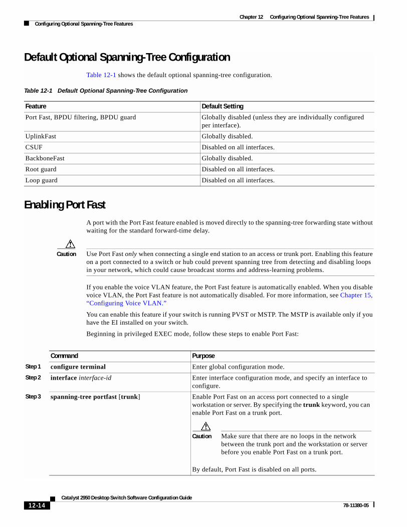
Chapter 12 Configuring Optional Spanning-Tree FeaturesConfiguring Optional Spanning-Tree Features
Default Optional Spanning-Tree ConfigurationTable 12-1 shows the default optional spanning-tree configuration.
Enabling Port FastA port with the Port Fast feature enabled is moved directly to the spanning-tree forwarding state without waiting for the standard forward-time delay.
Caution Use Port Fast only when connecting a single end station to an access or trunk port. Enabling this feature on a port connected to a switch or hub could prevent spanning tree from detecting and disabling loops in your network, which could cause broadcast storms and address-learning problems.
If you enable the voice VLAN feature, the Port Fast feature is automatically enabled. When you disable voice VLAN, the Port Fast feature is not automatically disabled. For more information, see Chapter 15, “Configuring Voice VLAN.”
You can enable this feature if your switch is running PVST or MSTP. The MSTP is available only if you have the EI installed on your switch.
Beginning in privileged EXEC mode, follow these steps to enable Port Fast:
Table 12-1 Default Optional Spanning-Tree Configuration
Feature Default Setting
Port Fast, BPDU filtering, BPDU guard Globally disabled (unless they are individually configured per interface).
UplinkFast Globally disabled.
CSUF Disabled on all interfaces.
BackboneFast Globally disabled.
Root guard Disabled on all interfaces.
Loop guard Disabled on all interfaces.
Command Purpose
Step 1 configure terminal Enter global configuration mode.
Step 2 interface interface-id Enter interface configuration mode, and specify an interface to configure.
Step 3 spanning-tree portfast [trunk] Enable Port Fast on an access port connected to a single workstation or server. By specifying the trunk keyword, you can enable Port Fast on a trunk port.
Caution Make sure that there are no loops in the network between the trunk port and the workstation or server before you enable Port Fast on a trunk port.
By default, Port Fast is disabled on all ports.
12-14Catalyst 2950 Desktop Switch Software Configuration Guide
78-11380-05

Chapter 12 Configuring Optional Spanning-Tree FeaturesConfiguring Optional Spanning-Tree Features
Note You can use the spanning-tree portfast default global configuration command to globally enable the Port Fast feature on all nontrunking ports.
To disable the Port Fast feature, use the spanning-tree portfast disable interface configuration command.
Enabling BPDU GuardWhen you globally enable BPDU guard on ports that are Port Fast-enabled (the ports are in a Port Fast-operational state), spanning tree shuts down Port Fast-enabled ports that receive BPDUs.
In a valid configuration, Port Fast-enabled ports do not receive BPDUs. Receiving a BPDU on a Port Fast-enabled port signals an invalid configuration, such as the connection of an unauthorized device, and the BPDU guard feature puts the port in the error-disabled state. The BPDU guard feature provides a secure response to invalid configurations because you must manually put the port back in service. Use the BPDU guard feature in a service-provider network to prevent an access port from participating in the spanning tree.
Caution Configure Port Fast only on ports that connect to end stations; otherwise, an accidental topology loop could cause a data packet loop and disrupt switch and network operation.
You can also use the spanning-tree bpduguard enable interface configuration command to enable BPDU guard on any port without also enabling the Port Fast feature. When the port receives a BPDU, it is put in the error-disabled state.
You can enable the BPDU guard feature if your switch is running PVST or MSTP. The MSTP is available only if you have the EI installed on your switch.
Beginning in privileged EXEC mode, follow these steps to globally enable the BPDU guard feature:
Step 4 end Return to privileged EXEC mode.
Step 5 show spanning-tree interface interface-id portfast
Verify your entries.
Step 6 copy running-config startup-config (Optional) Save your entries in the configuration file.
Command Purpose
Command Purpose
Step 1 configure terminal Enter global configuration mode.
Step 2 spanning-tree portfast bpduguard default Globally enable BPDU guard.
By default, BPDU guard is disabled.
Step 3 interface interface-id Enter interface configuration mode, and specify the interface connected to an end station.
Step 4 spanning-tree portfast Enable the Port Fast feature.
Step 5 end Return to privileged EXEC mode.
12-15Catalyst 2950 Desktop Switch Software Configuration Guide
78-11380-05

Chapter 12 Configuring Optional Spanning-Tree FeaturesConfiguring Optional Spanning-Tree Features
To disable BPDU guard, use the no spanning-tree portfast bpduguard default global configuration command.
You can override the setting of the no spanning-tree portfast bpduguard default global configuration command by using the spanning-tree bpduguard enable interface configuration command.
Enabling BPDU FilteringWhen you globally enable BPDU filtering on Port Fast-enabled ports, it prevents ports that are in a Port Fast-operational state from sending or receiving BPDUs. The ports still send a few BPDUs at link-up before the switch begins to filter outbound BPDUs. You should globally enable BPDU filtering on a switch so that hosts connected to these ports do not receive BPDUs. If a BPDU is received on a Port Fast-enabled port, the port loses its Port Fast-operational status, and BPDU filtering is disabled.
Caution Configure Port Fast only on ports that connect to end stations; otherwise, an accidental topology loop could cause a data packet loop and disrupt switch and network operation.
You can also use the spanning-tree bpdufilter enable interface configuration command to enable BPDU filtering on any port without also enabling the Port Fast feature. This command prevents the port from sending or receiving BPDUs.
Caution Enabling BPDU filtering on an interface is the same as disabling spanning tree on it and can result in spanning-tree loops.
You can enable the BPDU filtering feature if your switch is running PVST or MSTP. The MSTP is available only if you have the EI installed on your switch.
Beginning in privileged EXEC mode, follow these steps to globally enable the BPDU filtering feature:
Step 6 show running-config Verify your entries.
Step 7 copy running-config startup-config (Optional) Save your entries in the configuration file.
Command Purpose
Command Purpose
Step 1 configure terminal Enter global configuration mode.
Step 2 spanning-tree portfast bpdufilter default Globally enable BPDU filtering.
By default, BPDU filtering is disabled.
Step 3 interface interface-id Enter interface configuration mode, and specify the interface connected to an end station.
Step 4 spanning-tree portfast Enable the Port Fast feature.
Step 5 end Return to privileged EXEC mode.
Step 6 show running-config Verify your entries.
Step 7 copy running-config startup-config (Optional) Save your entries in the configuration file.
12-16Catalyst 2950 Desktop Switch Software Configuration Guide
78-11380-05

Chapter 12 Configuring Optional Spanning-Tree FeaturesConfiguring Optional Spanning-Tree Features
To disable BPDU filtering, use the no spanning-tree portfast bpdufilter default global configuration command.
You can override the setting of the no spanning-tree portfast bpdufilter default global configuration command by using the spanning-tree bpdufilter enable interface configuration command.
Enabling UplinkFast for Use with Redundant LinksUplinkFast cannot be enabled on VLANs that have been configured for switch priority. To enable UplinkFast on a VLAN with switch priority configured, first restore the switch priority on the VLAN to the default value by using the no spanning-tree vlan vlan-id priority global configuration command.
Note When you enable UplinkFast, it affects all VLANs on the switch. You cannot configure UplinkFast on an individual VLAN.
The UplinkFast feature is supported only when the switch is running PVST.
Beginning in privileged EXEC mode, follow these steps to enable UplinkFast:
When UplinkFast is enabled, the switch priority of all VLANs is set to 49152. If you change the path cost to a value less than 3000 and you enable UplinkFast or UplinkFast is already enabled, the path cost of all interfaces and VLAN trunks is increased by 3000 (if you change the path cost to 3000 or above, the path cost is not altered). The changes to the switch priority and the path cost reduces the chance that the switch will become the root switch.
When UplinkFast is disabled, the switch priorities of all VLANs and path costs of all interfaces are set to default values if you did not modify them from their defaults.
To return the update packet rate to the default setting, use the no spanning-tree uplinkfast max-update-rate global configuration command. To disable UplinkFast, use the no spanning-tree uplinkfast command.
Command Purpose
Step 1 configure terminal Enter global configuration mode.
Step 2 spanning-tree uplinkfast [max-update-rate pkts-per-second]
Enable UplinkFast.
(Optional) For pkts-per-second, the range is 0 to 65535 packets per second; the default is 150.
If you set the rate to 0, station-learning frames are not generated, and the spanning-tree topology converges more slowly after a loss of connectivity.
Step 3 end Return to privileged EXEC mode.
Step 4 show spanning-tree summary Verify your entries.
Step 5 copy running-config startup-config (Optional) Save your entries in the configuration file.
12-17Catalyst 2950 Desktop Switch Software Configuration Guide
78-11380-05

Chapter 12 Configuring Optional Spanning-Tree FeaturesConfiguring Optional Spanning-Tree Features
Enabling Cross-Stack UplinkFastBefore enabling CSUF, make sure your stack switches are properly connected. For more information, see the “Connecting the Stack Ports” section on page 12-8.
The CSUF feature is supported only when the switch is running PVST.
Beginning in privileged EXEC mode, follow these steps to enable CSUF:
To disable CSUF on an interface, use the no spanning-tree stack-port interface configuration command. To disable UplinkFast on the switch and all its VLANs, use the no spanning-tree uplinkfast global configuration command.
Command Purpose
Step 1 configure terminal Enter global configuration mode.
Step 2 spanning-tree uplinkfast [max-update-rate pkts-per-second]
Enable UplinkFast on the switch.
(Optional) For max-update-rate pkts-per-second, specify the number of packets per second at which update packets are sent. The range is 0 to 65535; the default is 150 packets per second.
Step 1 interface interface-id Enter interface configuration mode, and specify the GBIC interface on which to enable CSUF.
Step 2 spanning-tree stack-port Enable CSUF on only one stack-port GBIC interface.
The stack port connects to the GigaStack GBIC multidrop backbone. If you try to enable CSUF on a Fast Ethernet or a Gigabit-capable Ethernet port, you receive an error message.
If CSUF is already enabled on an interface and you try to enable it on another interface, you receive an error message. You must disable CSUF on the first interface before enabling it on a new interface.
Use this command only on access switches.
Step 3 end Return to privileged EXEC mode.
Step 4 show running-config Verify your entries.
Step 5 copy running-config startup-config (Optional) Save your entries in the configuration file.
12-18Catalyst 2950 Desktop Switch Software Configuration Guide
78-11380-05

Chapter 12 Configuring Optional Spanning-Tree FeaturesConfiguring Optional Spanning-Tree Features
Enabling BackboneFastYou can enable BackboneFast to detect indirect link failures and to start the spanning-tree reconfiguration sooner.
Note If you use BackboneFast, you must enable it on all switches in the network. BackboneFast is not supported on Token Ring VLANs. This feature is supported for use with third-party switches.
The BackboneFast feature is supported only when the switch is running PVST.
Beginning in privileged EXEC mode, follow these steps to enable BackboneFast:
To disable the BackboneFast feature, use the no spanning-tree backbonefast global configuration command.
Enabling Root GuardRoot guard enabled on an interface applies to all the VLANs to which the interface belongs.
Do not enable the root guard on interfaces to be used by the UplinkFast feature. With UplinkFast, the backup interfaces (in the blocked state) replace the root port in the case of a failure. However, if root guard is also enabled, all the backup interfaces used by the UplinkFast feature are placed in the root-inconsistent state (blocked) and are prevented from reaching the forwarding state.
Note You cannot enable both root guard and loop guard at the same time.
You can enable this feature if your switch is running PVST or MSTP. The MSTP is available only if you have the EI installed on your switch.
Beginning in privileged EXEC mode, follow these steps to enable root guard on an interface:
Command Purpose
Step 1 configure terminal Enter global configuration mode.
Step 2 spanning-tree backbonefast Enable BackboneFast.
Step 3 end Return to privileged EXEC mode.
Step 4 show spanning-tree summary Verify your entries.
Step 5 copy running-config startup-config (Optional) Save your entries in the configuration file.
Command Purpose
Step 1 configure terminal Enter global configuration mode.
Step 2 interface interface-id Enter interface configuration mode, and specify an interface to configure.
Step 3 spanning-tree guard root Enable root guard on the interface.
By default, root guard is disabled on all interfaces.
Step 4 end Return to privileged EXEC mode.
12-19Catalyst 2950 Desktop Switch Software Configuration Guide
78-11380-05

Chapter 12 Configuring Optional Spanning-Tree FeaturesConfiguring Optional Spanning-Tree Features
To disable root guard, use the no spanning-tree guard interface configuration command.
Enabling Loop GuardYou can use loop guard to prevent alternate or root ports from becoming designated ports because of a failure that leads to a unidirectional link. This feature is most effective when it is configured on the entire switched network. Loop guard operates only on ports that are considered point-to-point by the spanning tree.
Note You cannot enable both loop guard and root guard at the same time.
You can enable this feature if your switch is running PVST or MSTP. The MSTP is available only if you have the EI installed on your switch.
Beginning in privileged EXEC mode, follow these steps to enable loop guard:
To globally disable loop guard, use the no spanning-tree loopguard default global configuration command. You can override the setting of the no spanning-tree loopguard default global configuration command by using the spanning-tree guard loop interface configuration command.
Step 5 show running-config Verify your entries.
Step 6 copy running-config startup-config (Optional) Save your entries in the configuration file.
Command Purpose
Command Purpose
Step 1 show spanning-tree active
or
show spanning-tree mst
Determine which ports are alternate or root ports.
Step 2 configure terminal Enter global configuration mode.
Step 3 spanning-tree loopguard default Enable loop guard.
By default, loop guard is disabled.
Step 4 end Return to privileged EXEC mode.
Step 5 show running-config Verify your entries.
Step 6 copy running-config startup-config (Optional) Save your entries in the configuration file.
12-20Catalyst 2950 Desktop Switch Software Configuration Guide
78-11380-05

Chapter 12 Configuring Optional Spanning-Tree FeaturesDisplaying the Spanning-Tree Status
Displaying the Spanning-Tree StatusTo display the spanning-tree status, use one or more of the privileged EXEC commands in Table 12-2:
For information about other keywords for the show spanning-tree privileged EXEC command, refer to the command reference for this release.
Table 12-2 Commands for Displaying the Spanning-Tree Status
Command Purpose
show spanning-tree active Displays spanning-tree information on active interfaces only.
show spanning-tree detail Displays a detailed summary of interface information.
show spanning-tree interface interface-id Displays spanning-tree information for the specified interface.
show spanning-tree mst interface interface-id Displays MST information for the specified interface.
show spanning-tree summary [totals] Displays a summary of port states or displays the total lines of the spanning-tree state section.
12-21Catalyst 2950 Desktop Switch Software Configuration Guide
78-11380-05

Chapter 12 Configuring Optional Spanning-Tree FeaturesDisplaying the Spanning-Tree Status
12-22Catalyst 2950 Desktop Switch Software Configuration Guide
78-11380-05

Catalyst 2950 Deskto78-11380-05
C H A P T E R 13
Configuring VLANsThis chapter describes how to configure normal-range VLANs (VLAN IDs 1 to 1005) and extended-range VLANs (VLAN IDs 1006 to 4094). It includes information about VLAN modes and the VLAN Membership Policy Server (VMPS).
Note For complete syntax and usage information for the commands used in this chapter, refer to the command reference for this release.
The chapter includes these sections:
• Understanding VLANs, page 13-1
• Configuring Normal-Range VLANs, page 13-4
• Configuring Extended-Range VLANs, page 13-12
• Displaying VLANs, page 13-14
• Configuring VLAN Trunks, page 13-15
• Configuring VMPS, page 13-24
Understanding VLANsA VLAN is a switched network that is logically segmented by function, project team, or application, without regard to the physical locations of the users. VLANs have the same attributes as physical LANs, but you can group end stations even if they are not physically located on the same LAN segment. Any switch port can belong to a VLAN, and unicast, broadcast, and multicast packets are forwarded and flooded only to end stations in the VLAN. Each VLAN is considered a logical network, and packets destined for stations that do not belong to the VLAN must be forwarded through a router or bridge as shown in Figure 13-1. Because a VLAN is considered a separate logical network, it contains its own bridge Management Information Base (MIB) information and can support its own implementation of spanning tree. See Chapter 10, “Configuring STP” and Chapter 11, “Configuring RSTP and MSTP.”
Note Before you create VLANs, you must decide whether to use VLAN Trunking Protocol (VTP) to maintain global VLAN configuration for your network. For more information on VTP, see Chapter 14, “Configuring VTP.”
13-1p Switch Software Configuration Guide

Chapter 13 Configuring VLANsUnderstanding VLANs
Figure 13-1 shows an example of VLANs segmented into logically defined networks.
Figure 13-1 VLANs as Logically Defined Networks
VLANs are often associated with IP subnetworks. For example, all the end stations in a particular IP subnet belong to the same VLAN. Interface VLAN membership on the switch is assigned manually on an interface-by-interface basis. When you assign switch interfaces to VLANs by using this method, it is known as interface-based, or static, VLAN membership.
Supported VLANsCatalyst 2950 switches that run the standard software image (SI) support 64 VLANs; switches that run the enhanced software image (EI) support 250 VLANs. Refer to the release notes for the list of switches that support each image. VLANs are identified with a number from 1 to 4094 when the EI is installed and 1 to 1005 when the SI is installed. VLAN IDs 1002 through 1005 are reserved for Token Ring and FDDI VLANs. VTP only learns normal-range VLANs, with VLAN IDs 1 to 1005; VLAN IDs greater than 1005 are extended-range VLANs and are not stored in the VLAN database. The switch must be in VTP transparent mode when you create VLAN IDs from 1006 to 4094.
The switch supports per-VLAN spanning tree (PVST) with a maximum of 64 spanning-tree instances. One spanning-tree instance is allowed per VLAN. See the “Normal-Range VLAN Configuration Guidelines” section on page 13-5 for more information about the number of spanning-tree instances and the number of VLANs. The switch supports IEEE 802.1Q trunking for sending VLAN traffic over Ethernet ports.
Floor 1
Floor 2
EngineeringVLAN
Cisco router
Fast Ethernet
Floor 3
MarketingVLAN
AccountingVLAN
1675
1
13-2Catalyst 2950 Desktop Switch Software Configuration Guide
78-11380-05
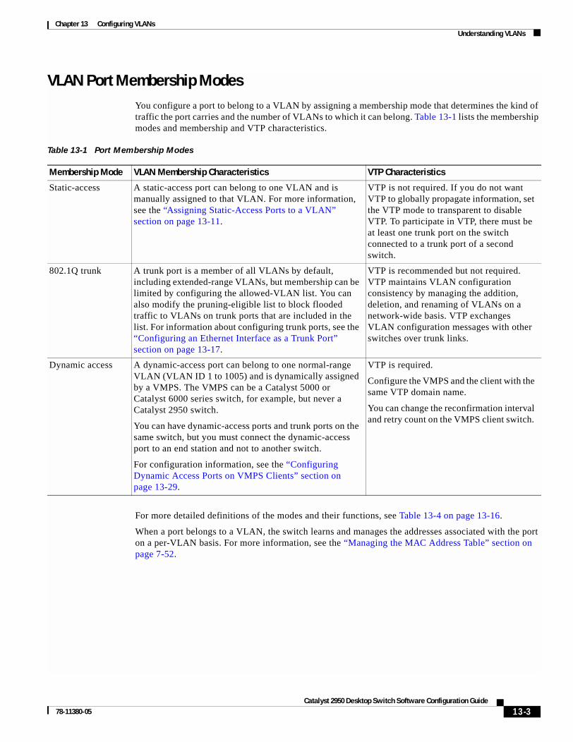
Chapter 13 Configuring VLANsUnderstanding VLANs
VLAN Port Membership ModesYou configure a port to belong to a VLAN by assigning a membership mode that determines the kind of traffic the port carries and the number of VLANs to which it can belong. Table 13-1 lists the membership modes and membership and VTP characteristics.
For more detailed definitions of the modes and their functions, see Table 13-4 on page 13-16.
When a port belongs to a VLAN, the switch learns and manages the addresses associated with the port on a per-VLAN basis. For more information, see the “Managing the MAC Address Table” section on page 7-52.
Table 13-1 Port Membership Modes
Membership Mode VLAN Membership Characteristics VTP Characteristics
Static-access A static-access port can belong to one VLAN and is manually assigned to that VLAN. For more information, see the “Assigning Static-Access Ports to a VLAN” section on page 13-11.
VTP is not required. If you do not want VTP to globally propagate information, set the VTP mode to transparent to disable VTP. To participate in VTP, there must be at least one trunk port on the switch connected to a trunk port of a second switch.
802.1Q trunk A trunk port is a member of all VLANs by default, including extended-range VLANs, but membership can be limited by configuring the allowed-VLAN list. You can also modify the pruning-eligible list to block flooded traffic to VLANs on trunk ports that are included in the list. For information about configuring trunk ports, see the “Configuring an Ethernet Interface as a Trunk Port” section on page 13-17.
VTP is recommended but not required. VTP maintains VLAN configuration consistency by managing the addition, deletion, and renaming of VLANs on a network-wide basis. VTP exchanges VLAN configuration messages with other switches over trunk links.
Dynamic access A dynamic-access port can belong to one normal-range VLAN (VLAN ID 1 to 1005) and is dynamically assigned by a VMPS. The VMPS can be a Catalyst 5000 or Catalyst 6000 series switch, for example, but never a Catalyst 2950 switch.
You can have dynamic-access ports and trunk ports on the same switch, but you must connect the dynamic-access port to an end station and not to another switch.
For configuration information, see the “Configuring Dynamic Access Ports on VMPS Clients” section on page 13-29.
VTP is required.
Configure the VMPS and the client with the same VTP domain name.
You can change the reconfirmation interval and retry count on the VMPS client switch.
13-3Catalyst 2950 Desktop Switch Software Configuration Guide
78-11380-05

Chapter 13 Configuring VLANsConfiguring Normal-Range VLANs
Configuring Normal-Range VLANsNormal-range VLANs are VLANs with VLAN IDs 1 to 1005. If the switch is in VTP server or transparent mode, you can add, modify or remove configurations for VLANs 2 to 1001 in the VLAN database. (VLAN IDs 1 and 1002 to 1005 are automatically created and cannot be removed.)
Note When the switch is in VTP transparent mode and the EI is installed, you can also create extended-range VLANs (VLANs with IDs from 1006 to 4094), but these VLANs are not saved in the VLAN database. See the “Configuring Extended-Range VLANs” section on page 13-12.
Configurations for VLAN IDs 1 to 1005 are written to the file vlan.dat (VLAN database), and you can display them by entering the show vlan privileged EXEC command. The vlan.dat file is stored in nonvolatile RAM (NVRAM).
Caution You can cause inconsistency in the VLAN database if you attempt to manually delete the vlan.dat file. If you want to modify the VLAN configuration, use the commands described in these sections and in the command reference for this release. To change the VTP configuration, see Chapter 14, “Configuring VTP.”
You use the interface configuration mode to define the port membership mode and to add and remove ports from VLANs. The results of these commands are written to the running-configuration file, and you can display the file by entering the show running-config privileged EXEC command.
You can set these parameters when you create a new normal-range VLAN or modify an existing VLAN in the VLAN database:
• VLAN ID
• VLAN name
• VLAN type (Ethernet, Fiber Distributed Data Interface [FDDI], FDDI network entity title [NET], TrBRF, or TrCRF, Token Ring, Token Ring-Net)
• VLAN state (active or suspended)
• Maximum transmission unit (MTU) for the VLAN
• Security Association Identifier (SAID)
• Bridge identification number for TrBRF VLANs
• Ring number for FDDI and TrCRF VLANs
• Parent VLAN number for TrCRF VLANs
• Spanning Tree Protocol (STP) type for TrCRF VLANs
• VLAN number to use when translating from one VLAN type to another
Note This section does not provide configuration details for most of these parameters. For complete information on the commands and parameters that control VLAN configuration, refer to the command reference for this release.
13-4Catalyst 2950 Desktop Switch Software Configuration Guide
78-11380-05

Chapter 13 Configuring VLANsConfiguring Normal-Range VLANs
This section includes information about these topics about normal-range VLANs:
• Token Ring VLANs, page 13-5
• Normal-Range VLAN Configuration Guidelines, page 13-5
• VLAN Configuration Mode Options, page 13-6
• Saving VLAN Configuration, page 13-7
• Default Ethernet VLAN Configuration, page 13-8
• Creating or Modifying an Ethernet VLAN, page 13-8
• Deleting a VLAN, page 13-10
• Assigning Static-Access Ports to a VLAN, page 13-11
Token Ring VLANsAlthough the switch does not support Token Ring connections, a remote device such as a Catalyst 5000 series switch with Token Ring connections could be managed from one of the supported switches. Switches running VTP version 2 advertise information about these Token Ring VLANs:
• Token Ring TrBRF VLANs
• Token Ring TrCRF VLANs
For more information on configuring Token Ring VLANs, refer to the Catalyst 5000 Series Software Configuration Guide.
Normal-Range VLAN Configuration Guidelines Follow these guidelines when creating and modifying normal-range VLANs in your network:
• See Table 13-1 for the maximum number of supported VLANs per switch model. On a switch supporting 250 VLANs, if VTP reports that there are 254 active VLANs, four of the active VLANs (1002 to 1005) are reserved for Token Ring and FDDI.
• Normal-range VLANs are identified with a number between 1 and 1001. VLAN numbers 1002 through 1005 are reserved for Token Ring and FDDI VLANs.
• VLAN configuration for VLANs 1 to 1005 are always saved in the VLAN database. If VTP mode is transparent, VTP and VLAN configuration is also saved in the switch running configuration file.
• The switch also supports VLAN IDs 1006 through 4094 in VTP transparent mode (VTP disabled) when the EI is installed. These are extended-range VLANs and configuration options are limited. Extended-range VLANs are not saved in the VLAN database. See the “Configuring Extended-Range VLANs” section on page 13-12.
• Before you can create a VLAN, the switch must be in VTP server mode or VTP transparent mode. If the switch is a VTP server, you must define a VTP domain or VTP will not function.
• The switch does not support Token Ring or FDDI media. The switch does not forward FDDI, FDDI-Net, TrCRF, or TrBRF traffic, but it does propagate the VLAN configuration through VTP.
• The switch supports 64 spanning-tree instances. If a switch has more active VLANs than supported spanning-tree instances, spanning tree can be enabled on 64 VLANs and is disabled on the remaining VLANs. If you have already used all available spanning-tree instances on a switch, adding another VLAN anywhere in the VTP domain creates a VLAN on that switch that is not running spanning-tree. If you have the default allowed list on the trunk ports of that switch (which
13-5Catalyst 2950 Desktop Switch Software Configuration Guide
78-11380-05

Chapter 13 Configuring VLANsConfiguring Normal-Range VLANs
is to allow all VLANs), the new VLAN is carried on all trunk ports. Depending on the topology of the network, this could create a loop in the new VLAN that would not be broken, particularly if there are several adjacent switches that all have run out of spanning-tree instances. You can prevent this possibility by setting allowed lists on the trunk ports of switches that have used up their allocation of spanning-tree instances.
If the number of VLANs on the switch exceeds the number of supported spanning tree instances, we recommend that you configure the IEEE 802.1S Multiple STP (MSTP) on your switch to map multiple VLANs to a single STP instance. For more information about MSTP, see Chapter 11, “Configuring RSTP and MSTP.”
VLAN Configuration Mode OptionsYou can configure normal-range VLANs (with VLAN IDs 1 to 1005) by using these two configuration modes:
• VLAN Configuration in config-vlan Mode, page 13-6
You access config-vlan mode by entering the vlan vlan-id global configuration command.
• VLAN Configuration in VLAN Configuration Mode, page 13-6
You access VLAN configuration mode by entering the vlan database privileged EXEC command.
VLAN Configuration in config-vlan Mode
To access config-vlan mode, enter the vlan global configuration command with a VLAN ID. Enter a new VLAN ID to create a VLAN or with an existing VLAN ID to modify the VLAN. You can use the default VLAN configuration (Table 13-2) or enter multiple commands to configure the VLAN. For more information about commands available in this mode, refer to the vlan global configuration command description in the command reference for this release. When you have finished the configuration, you must exit config-vlan mode for the configuration to take effect. To display the VLAN configuration, enter the show vlan privileged EXEC command.
You must use this config-vlan mode when creating extended-range VLANs (VLAN IDs greater than 1005). See the “Configuring Extended-Range VLANs” section on page 13-12.
VLAN Configuration in VLAN Configuration Mode
To access VLAN configuration mode, enter the vlan database privileged EXEC command. Then enter the vlan command with a new VLAN ID to create a VLAN or with an existing VLAN ID to modify the VLAN. You can use the default VLAN configuration (Table 13-2) or enter multiple commands to configure the VLAN. For more information about keywords available in this mode, refer to the vlan VLAN configuration command description in the command reference for this release. When you have finished the configuration, you must enter apply or exit for the configuration to take effect. When you enter the exit command, it applies all commands and updates the VLAN database. VTP messages are sent to other switches in the VTP domain, and the privileged EXEC mode prompt appears.
13-6Catalyst 2950 Desktop Switch Software Configuration Guide
78-11380-05

Chapter 13 Configuring VLANsConfiguring Normal-Range VLANs
Saving VLAN ConfigurationThe configurations of VLAN IDs 1 to 1005 are always saved in the VLAN database (vlan.dat file). If VTP mode is transparent, they are also saved in the switch running configuration file and you can enter the copy running-config startup-config privileged EXEC command to save the configuration in the startup configuration file. You can use the show running-config vlan privileged EXEC command to display the switch running configuration file. To display the VLAN configuration, enter the show vlan privileged EXEC command.
When you save VLAN and VTP information (including extended-range VLAN configuration information) in the startup configuration file and reboot the switch, the switch configuration is determined as follows:
• If the VTP mode is transparent in the startup configuration, and the VLAN database and the VTP domain name from the VLAN database matches that in the startup configuration file, the VLAN database is ignored (cleared), and the VTP and VLAN configurations in the startup configuration file are used. The VLAN database revision number remains unchanged in the VLAN database.
• If the VTP mode or domain name in the startup configuration does not match the VLAN database, the domain name and VTP mode and configuration for the first 1005 VLANs use the VLAN database information.
• If VTP mode is server, the domain name and VLAN configuration for the first 1005 VLANs use the VLAN database information
• If the switch is running IOS Release 12.1(9)EA1 or later and you use an older startup configuration file to boot up the switch, the configuration file does not contain VTP or VLAN information, and the switch uses the VLAN database configurations.
• If the switch is running an IOS release earlier than 12.1(9)EA1 and you use a startup configuration file from IOS Release 12.1(9)EA1 or later to boot up the switch, the image on the switch does not recognize the VLAN and VTP configurations in the startup configuration file, so the switch uses the VLAN database configuration.
Caution If the VLAN database configuration is used at startup and the startup configuration file contains extended-range VLAN configuration, this information is lost when the system boots up.
13-7Catalyst 2950 Desktop Switch Software Configuration Guide
78-11380-05
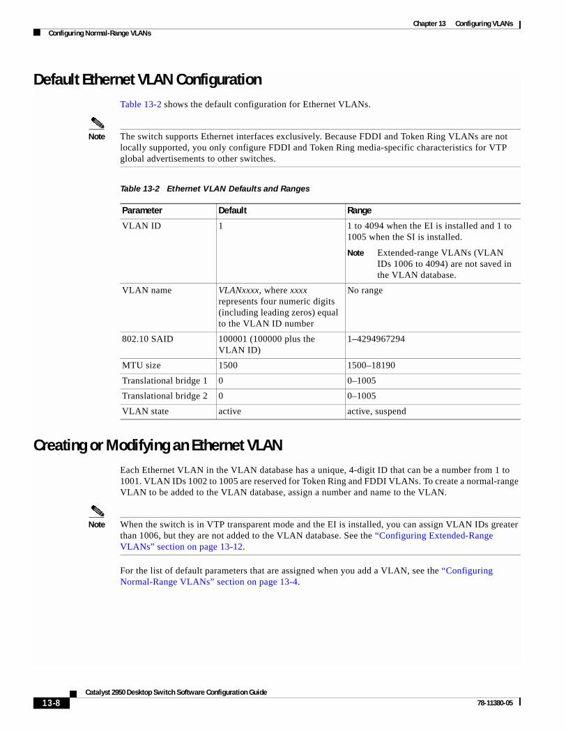
Chapter 13 Configuring VLANsConfiguring Normal-Range VLANs
Default Ethernet VLAN ConfigurationTable 13-2 shows the default configuration for Ethernet VLANs.
Note The switch supports Ethernet interfaces exclusively. Because FDDI and Token Ring VLANs are not locally supported, you only configure FDDI and Token Ring media-specific characteristics for VTP global advertisements to other switches.
Creating or Modifying an Ethernet VLANEach Ethernet VLAN in the VLAN database has a unique, 4-digit ID that can be a number from 1 to 1001. VLAN IDs 1002 to 1005 are reserved for Token Ring and FDDI VLANs. To create a normal-range VLAN to be added to the VLAN database, assign a number and name to the VLAN.
Note When the switch is in VTP transparent mode and the EI is installed, you can assign VLAN IDs greater than 1006, but they are not added to the VLAN database. See the “Configuring Extended-Range VLANs” section on page 13-12.
For the list of default parameters that are assigned when you add a VLAN, see the “Configuring Normal-Range VLANs” section on page 13-4.
Table 13-2 Ethernet VLAN Defaults and Ranges
Parameter Default Range
VLAN ID 1 1 to 4094 when the EI is installed and 1 to 1005 when the SI is installed.
Note Extended-range VLANs (VLAN IDs 1006 to 4094) are not saved in the VLAN database.
VLAN name VLANxxxx, where xxxx represents four numeric digits (including leading zeros) equal to the VLAN ID number
No range
802.10 SAID 100001 (100000 plus the VLAN ID)
1–4294967294
MTU size 1500 1500–18190
Translational bridge 1 0 0–1005
Translational bridge 2 0 0–1005
VLAN state active active, suspend
13-8Catalyst 2950 Desktop Switch Software Configuration Guide
78-11380-05

Chapter 13 Configuring VLANsConfiguring Normal-Range VLANs
Beginning in privileged EXEC mode, follow these steps to use config-vlan mode to create or modify an Ethernet VLAN:
To return the VLAN name to the default settings, use the no vlan name or no vlan mtu config-vlan commands.
This example shows how to use config-vlan mode to create Ethernet VLAN 20, name it test20, and add it to the VLAN database:
Switch# configure terminalSwitch(config)# vlan 20Switch(config-vlan)# name test20Switch(config-vlan)# end
Beginning in privileged EXEC mode, follow these steps to use VLAN configuration mode to create or modify an Ethernet VLAN:
Command Purpose
Step 1 configure terminal Enter global configuration mode.
Step 2 vlan vlan-id Enter a VLAN ID, and enter config-vlan mode. Enter a new VLAN ID to create a VLAN, or enter an existing VLAN ID to modify a VLAN.
Note The available VLAN ID range for this command is 1 to 1005 when the SI is installed and 1 to 4094 when the EI is installed; do not enter leading zeros. For information about adding VLAN IDs greater than 1005 (extended-range VLANs), see the “Configuring Extended-Range VLANs” section on page 13-12.
Step 3 name vlan-name (Optional) Enter a name for the VLAN. If no name is entered for the VLAN, the default is to append the vlan-id with leading zeros to the word VLAN. For example, VLAN0004 is a default VLAN name for VLAN 4.
Step 4 mtu mtu-size (Optional) Change the MTU size (or other VLAN characteristic).
Step 5 end Return to privileged EXEC mode.
Step 6 show vlan {name vlan-name | id vlan-id} Verify your entries.
Step 7 copy running-config startup config (Optional) If the switch is in VTP transparent mode, the VLAN configuration is saved in the running configuration file as well as in the VLAN database. This saves the configuration in the switch startup configuration file.
Command Purpose
Step 1 vlan database Enter VLAN configuration mode.
Step 2 vlan vlan-id name vlan-name Add an Ethernet VLAN by assigning a number to it. The range is 1 to 1001; do not enter leading zeros.
If no name is entered for the VLAN, the default is to append the vlan-id with leading zeros to the word VLAN. For example, VLAN0004 is a default VLAN name for VLAN 4.
Step 3 vlan vlan-id mtu mtu-size (Optional) To modify a VLAN, identify the VLAN and change a characteristic, such as the MTU size.
13-9Catalyst 2950 Desktop Switch Software Configuration Guide
78-11380-05

Chapter 13 Configuring VLANsConfiguring Normal-Range VLANs
To return the VLAN name to the default settings, use the no vlan vlan-id name or no vlan vlan-id mtu VLAN configuration command.
This example shows how to use VLAN configuration mode to create Ethernet VLAN 20, name it test20, and add it to the VLAN database:
Switch# vlan databaseSwitch(vlan)# vlan 20 name test20Switch(vlan)# exitAPPLY completed.Exiting....Switch#
Deleting a VLANWhen you delete a VLAN from a switch that is in VTP server mode, the VLAN is removed from the VLAN database for all switches in the VTP domain. When you delete a VLAN from a switch that is in VTP transparent mode, the VLAN is deleted only on that specific switch.
You cannot delete the default VLANs for the different media types: Ethernet VLAN 1 and FDDI or Token Ring VLANs 1002 to 1005.
Caution When you delete a VLAN, any ports assigned to that VLAN become inactive. They remain associated with the VLAN (and thus inactive) until you assign them to a new VLAN.
Beginning in privileged EXEC mode, follow these steps to delete a VLAN on the switch by using global configuration mode:
To delete a VLAN by using VLAN configuration mode, use the vlan database privileged EXEC command to enter VLAN configuration mode and the no vlan vlan-id VLAN configuration command.
Step 4 exit Update the VLAN database, propagate it throughout the administrative domain, and return to privileged EXEC mode.
Step 5 show vlan {name vlan-name | id vlan-id} Verify your entries.
Step 6 copy running-config startup config (Optional) If the switch is in VTP transparent mode, the VLAN configuration is saved in the running configuration file as well as in the VLAN database. This saves the configuration in the switch startup configuration file.
Command Purpose
Command Purpose
Step 1 configure terminal Enter global configuration mode.
Step 2 no vlan vlan-id Remove the VLAN by entering the VLAN ID.
Step 3 end Return to privileged EXEC mode.
Step 4 show vlan brief Verify the VLAN removal.
Step 5 copy running-config startup config (Optional) If the switch is in VTP transparent mode, the VLAN configuration is saved in the running configuration file as well as in the VLAN database. This saves the configuration in the switch startup configuration file.
13-10Catalyst 2950 Desktop Switch Software Configuration Guide
78-11380-05

Chapter 13 Configuring VLANsConfiguring Normal-Range VLANs
Assigning Static-Access Ports to a VLANYou can assign a static-access port to a VLAN without having VTP globally propagate VLAN configuration information (VTP is disabled). If you are assigning a port on a cluster member switch to a VLAN, first use the rcommand privileged EXEC command to log in to the member switch.
Note If you assign an interface to a VLAN that does not exist, the new VLAN is created. (See the “Creating or Modifying an Ethernet VLAN” section on page 13-8.)
Beginning in privileged EXEC mode, follow these steps to assign a port to a VLAN in the VLAN database:
To return an interface to its default configuration, use the default interface interface-id interface configuration command.
This example shows how to configure Fast Ethernet interface 0/1 as an access port in VLAN 2:
Switch# configure terminal Enter configuration commands, one per line. End with CNTL/Z.Switch(config)# interface fastethernet0/1 Switch(config-if)# switchport mode access Switch(config-if)# switchport access vlan 2Switch(config-if)# end Switch#
Command Purpose
Step 1 configure terminal Enter global configuration mode
Step 2 interface interface-id Enter the interface to be added to the VLAN.
Step 3 switchport mode access Define the VLAN membership mode for the port (Layer 2 access port).
Step 4 switchport access vlan vlan-id Assign the port to a VLAN. Valid VLAN IDs are 1 to 4094; do not enter leading zeros.
Step 5 end Return to privileged EXEC mode.
Step 6 show running-config interface interface-id Verify the VLAN membership mode of the interface.
Step 7 show interfaces interface-id switchport Verify your entries in the Administrative Mode and the Access Mode VLAN fields of the display.
Step 8 copy running-config startup-config (Optional) Save your entries in the configuration file.
13-11Catalyst 2950 Desktop Switch Software Configuration Guide
78-11380-05

Chapter 13 Configuring VLANsConfiguring Extended-Range VLANs
Configuring Extended-Range VLANsWhen the switch is in VTP transparent mode (VTP disabled) and the EI is installed), you can create extended-range VLANs (in the range 1006 to 4094). Extended-range VLANs enable service providers to extend their infrastructure to a greater number of customers. The extended-range VLAN IDs are allowed for any switchport commands that allow VLAN IDs. You always use config-vlan mode (accessed by entering the vlan vlan-id global configuration command) to configure extended-range VLANs. The extended range is not supported in VLAN configuration mode (accessed by entering the vlan database privileged EXEC command).
Extended-range VLAN configurations are not stored in the VLAN database, but because VTP mode is transparent, they are stored in the switch running configuration file, and you can save the configuration in the startup configuration file by using the copy running-config startup-config privileged EXEC command.
Note Although the switch supports 4094 VLAN IDs when the EI is installed, see the “Supported VLANs” section on page 13-2 for the actual number of VLANs supported.
This section includes this information about extended-range VLANs:
• Default VLAN Configuration, page 13-12
• Extended-Range VLAN Configuration Guidelines, page 13-12
• Creating an Extended-Range VLAN, page 13-13
• Displaying VLANs, page 13-14
Default VLAN ConfigurationSee Table 13-2 on page 13-8 for the default configuration for Ethernet VLANs. You can change only the MTU size on extended-range VLANs; all other characteristics must remain at the default state.
Extended-Range VLAN Configuration GuidelinesFollow these guidelines when creating extended-range VLANs:
• To add an extended-range VLAN, you must use the vlan vlan-id global configuration command and access config-vlan mode. You cannot add extended-range VLANs in VLAN configuration mode (accessed by entering the vlan database privileged EXEC command).
• VLAN IDs in the extended range are not saved in the VLAN database and are not recognized by VTP.
• You cannot include extended-range VLANs in the pruning eligible range.
• The switch must be in VTP transparent mode when you create extended-range VLANs. If VTP mode is server or client, an error message is generated, and the extended-range VLAN is rejected.
• You can set the VTP mode to transparent in global configuration mode or in VLAN configuration mode. See the “Disabling VTP (VTP Transparent Mode)” section on page 14-12. You should save this configuration to the startup configuration so that the switch will boot up in VTP transparent mode. Otherwise, you will lose extended-range VLAN configuration if the switch resets.
• VLANs in the extended range are not supported by VQP. They cannot be configured by VMPS.
13-12Catalyst 2950 Desktop Switch Software Configuration Guide
78-11380-05

Chapter 13 Configuring VLANsConfiguring Extended-Range VLANs
• STP is enabled by default on extended-range VLANs, but you can disable it by using the no spanning-tree vlan vlan-id global configuration command. When the maximum number of spanning-tree instances (64) are on the switch, spanning tree is disabled on any newly created VLANs. If the number of VLANs on the switch exceeds the maximum number of spanning tree instances, we recommend that you configure the IEEE 802.1S Multiple STP (MSTP) on your switch to map multiple VLANs to a single STP instance. For more information about MSTP, see Chapter 11, “Configuring RSTP and MSTP.”
Creating an Extended-Range VLANYou create an extended-range VLAN in global configuration mode by entering the vlan global configuration command with a VLAN ID from 1006 to 4094. This command accesses the config-vlan mode. The extended-range VLAN has the default Ethernet VLAN characteristics (see Table 13-2) and the MTU size is the only parameter you can change. Refer to the description of the vlan global configuration command in the command reference for defaults of all parameters. If you enter an extended-range VLAN ID when the switch is not in VTP transparent mode, an error message is generated when you exit from config-vlan mode, and the extended-range VLAN is not created.
Extended-range VLANs are not saved in the VLAN database; they are saved in the switch running configuration file. You can save the extended-range VLAN configuration in the switch startup configuration file by using the copy running-config startup-config privileged EXEC command.
Note Before you create an extended-range VLAN, you can verify that the VLAN ID is not used internally by entering the show vlan internal usage privileged EXEC command. If the VLAN ID is used internally and you want to free it up, go to the“Displaying VLANs” section on page 13-14 before creating the extended-range VLAN.
Beginning in privileged EXEC mode, follow these steps to create an extended-range VLAN:
Command Purpose
Step 1 configure terminal Enter global configuration mode.
Step 2 vtp mode transparent Configure the switch for VTP transparent mode, disabling VTP.
Step 3 vlan vlan-id Enter an extended-range VLAN ID and enter config-vlan mode. The range is 1006 to 4094.
Step 4 mtu mtu-size (Optional) Modify the VLAN by changing the MTU size.
Note Although all commands appear in the CLI help in config-vlan mode, only the mtu mtu-size command is supported for extended-range VLANs.
Step 5 end Return to privileged EXEC mode.
Step 6 show vlan id vlan-id Verify that the VLAN has been created.
Step 7 copy running-config startup config Save your entries in the switch startup configuration file. To save extended-range VLAN configurations, you need to save the VTP transparent mode configuration and the extended-range VLAN configuration in the switch startup configuration file. Otherwise, if the switch resets, it will default to VTP server mode, and the extended-range VLAN IDs will not be saved.
13-13Catalyst 2950 Desktop Switch Software Configuration Guide
78-11380-05

Chapter 13 Configuring VLANsDisplaying VLANs
To delete an extended-range VLAN, use the no vlan vlan-id global configuration command.
The procedure for assigning static-access ports to an extended-range VLAN is the same as for normal-range VLANs. See the “Assigning Static-Access Ports to a VLAN” section on page 13-11.
This example shows how to create a new extended-range VLAN (when the EI is installed) with all default characteristics, enter config-vlan mode, and save the new VLAN in the switch startup configuration file:
Switch(config)# vtp mode transparentSwitch(config)# vlan 2000Switch(config-vlan)# endSwitch# copy running-config startup config
Displaying VLANsUse the show vlan privileged EXEC command to display a list of all VLANs on the switch, including extended-range VLANs. The display includes VLAN status, ports, and configuration information. To view normal-range VLANs in the VLAN database (1 to 1005,) use the show VLAN configuration command (accessed by entering the vlan database privileged EXEC command). For a list of the VLAN IDs on the switch, use the show running-config vlan privileged EXEC command, optionally entering a VLAN ID range.
Table 13-3 lists the commands for monitoring VLANs.
For more details about the show command options and explanations of output fields, refer to the command reference for this release.
Table 13-3 VLAN Monitoring Commands
Command Command Mode Purpose
show VLAN configuration Display status of VLANs in the VLAN database.
show current [vlan-id] VLAN configuration Display status of all or the specified VLAN in the VLAN database.
show interfaces [vlan vlan-id]
Privileged EXEC Display characteristics for all interfaces or for the specified VLAN configured on the switch.
show running-config vlan Privileged EXEC Display all or a range of VLANs on the switch.
show vlan [id vlan-id] Privileged EXEC Display parameters for all VLANs or the specified VLAN on the switch.
13-14Catalyst 2950 Desktop Switch Software Configuration Guide
78-11380-05

Chapter 13 Configuring VLANsConfiguring VLAN Trunks
Configuring VLAN TrunksThese sections describe how VLAN trunks function on the switch:
• Trunking Overview, page 13-15
• 802.1Q Configuration Considerations, page 13-16
• Default Layer 2 Ethernet Interface VLAN Configuration, page 13-17
Trunking OverviewA trunk is a point-to-point link between one or more Ethernet switch interfaces and another networking device such as a router or a switch. Fast Ethernet and Gigabit Ethernet trunks carry the traffic of multiple VLANs over a single link, and you can extend the VLANs across an entire network.
Figure 13-2 shows a network of switches that are connected by 802.1Q trunks.
Figure 13-2 Catalyst 2950, 2900 XL, and 3500 XL Switches in a 802.1Q Trunking Environment
You can configure a trunk on a single Ethernet interface or on an EtherChannel bundle. For more information about EtherChannel, see Chapter 26, “Configuring EtherChannels.”
Ethernet trunk interfaces support different trunking modes (see Table 13-4). You can set an interface as trunking or nontrunking or to negotiate trunking with the neighboring interface. To autonegotiate trunking, the interfaces must be in the same VTP domain.
Trunk negotiation is managed by the Dynamic Trunking Protocol (DTP), which is a Point-to-Point Protocol. However, some internetworking devices might forward DTP frames improperly, which could cause misconfigurations.
Catalyst 6000 seriesswitch
Catalyst2900 XL
switch Catalyst3500 XL
switch
Catalyst2950 switch
Catalyst 3500 XLswitch
VLAN2
VLAN3VLAN1
VLAN1
VLAN2
VLAN3
802.1Qtrunk
802.1Qtrunk
802.1Qtrunk
802.1Qtrunk
4496
2
13-15Catalyst 2950 Desktop Switch Software Configuration Guide
78-11380-05

Chapter 13 Configuring VLANsConfiguring VLAN Trunks
To avoid this, you should configure interfaces connected to devices that do not support DTP to not forward DTP frames, that is, to turn off DTP.
• If you do not intend to trunk across those links, use the switchport mode access interface configuration command to disable trunking.
• To enable trunking to a device that does not support DTP, use the switchport mode trunk and switchport nonegotiate interface configuration commands to cause the interface to become a trunk but to not generate DTP frames.
Note On GigaStack GBICs, dynamic trunking is only supported when only one port of a GigaStack GBIC is being used. If trunking is required on a GigaStack GBIC where both ports are in use, use the switchport mode trunk and switchport nonegotiate interface configuration commands on both GBIC interfaces to cause the interfaces to become trunks.
802.1Q Configuration Considerations
802.1Q trunks impose these limitations on the trunking strategy for a network:
• In a network of Cisco switches connected through 802.1Q trunks, the switches maintain one instance of spanning tree for each VLAN allowed on the trunks. Non-Cisco devices might support one spanning-tree instance for all VLANs.
When you connect a Cisco switch to a non-Cisco device through an 802.1Q trunk, the Cisco switch combines the spanning-tree instance of the VLAN of the trunk with the spanning-tree instance of the non-Cisco 802.1Q switch. However, spanning-tree information for each VLAN is maintained by Cisco switches separated by a cloud of non-Cisco 802.1Q switches. The non-Cisco 802.1Q cloud separating the Cisco switches is treated as a single trunk link between the switches.
• Make sure the native VLAN for an 802.1Q trunk is the same on both ends of the trunk link. If the native VLAN on one end of the trunk is different from the native VLAN on the other end, spanning-tree loops might result.
Table 13-4 Layer 2 Interface Modes
Mode Function
switchport mode access Puts the interface (access port) into permanent nontrunking mode and negotiates to convert the link into a nontrunk link. The interface becomes a nontrunk interface even if the neighboring interface is not a trunk interface.
switchport mode dynamic desirable
Makes the interface actively attempt to convert the link to a trunk link. The interface becomes a trunk interface if the neighboring interface is set to trunk, desirable, or auto mode. The default switch-port mode for all Ethernet interfaces is dynamic desirable.
switchport mode dynamic auto Makes the interface able to convert the link to a trunk link. The interface becomes a trunk interface if the neighboring interface is set to trunk or desirable mode.
switchport mode trunk Puts the interface into permanent trunking mode and negotiates to convert the link into a trunk link. The interface becomes a trunk interface even if the neighboring interface is not a trunk interface.
switchport nonegotiate Prevents the interface from generating DTP frames. You can use this command only when the interface switchport mode is access or trunk. You must manually configure the neighboring interface as a trunk interface to establish a trunk link.
13-16Catalyst 2950 Desktop Switch Software Configuration Guide
78-11380-05

Chapter 13 Configuring VLANsConfiguring VLAN Trunks
• Disabling spanning tree on the native VLAN of an 802.1Q trunk without disabling spanning tree on every VLAN in the network can potentially cause spanning-tree loops. We recommend that you leave spanning tree enabled on the native VLAN of an 802.1Q trunk or disable spanning tree on every VLAN in the network. Make sure your network is loop-free before disabling spanning tree.
Default Layer 2 Ethernet Interface VLAN ConfigurationTable 13-5 shows the default Layer 2 Ethernet interface VLAN configuration.
Configuring an Ethernet Interface as a Trunk PortBecause trunk ports send and receive VTP advertisements, to use VTP you must ensure that at least one trunk port is configured on the switch and that this trunk port is connected to the trunk port of a second switch. Otherwise, the switch cannot receive any VTP advertisements.
This section includes these procedures for configuring an Ethernet interface as a trunk port on the switch:
• Interaction with Other Features, page 13-17
• Defining the Allowed VLANs on a Trunk, page 13-19
• Changing the Pruning-Eligible List, page 13-20
• Configuring the Native VLAN for Untagged Traffic, page 13-20
Note The default mode for Layer 2 interfaces is switchport mode dynamic desirable. If the neighboring interface supports trunking and is configured to allow trunking, the link is a Layer 2 trunk.
Interaction with Other Features
Trunking interacts with other features in these ways:
• A trunk port cannot be a secure port.
• Trunk ports can be grouped into EtherChannel port groups, but all trunks in the group must have the same configuration. When a group is first created, all ports follow the parameters set for the first port to be added to the group. If you change the configuration of one of these parameters, the switch propagates the setting you entered to all ports in the group:
– allowed-VLAN list
– STP port priority for each VLAN
Table 13-5 Default Layer 2 Ethernet Interface VLAN Configuration
Feature Default Setting
Interface mode switchport mode dynamic desirable
Allowed VLAN range VLANs 1 to 4094 when the EI is installed and 1 to 1005 when the SI is installed
VLAN range eligible for pruning VLANs 2 to 1001
Default VLAN (for access ports) VLAN 1
Native VLAN (for 802.1Q trunks) VLAN 1
13-17Catalyst 2950 Desktop Switch Software Configuration Guide
78-11380-05

Chapter 13 Configuring VLANsConfiguring VLAN Trunks
– STP Port Fast setting
– trunk status: if one port in a port group ceases to be a trunk, all ports cease to be trunks.
• If you try to enable 802.1X on a trunk port, an error message appears, and 802.1X is not enabled. If you try to change the mode of an 802.1X-enabled port to trunk, the port mode is not changed.
• A port in dynamic mode can negotiate with its neighbor to become a trunk port. If you try to enable 802.1X on a dynamic port, an error message appears, and 802.1X is not enabled. If you try to change the mode of an 802.1X-enabled port to dynamic, the port mode is not changed.
Configuring a Trunk Port
Beginning in privileged EXEC mode, follow these steps to configure a port as 802.1Q trunk port:
To return an interface to its default configuration, use the default interface interface-id interface configuration command. To reset all trunking characteristics of a trunking interface to the defaults, use the no switchport trunk interface configuration command. To disable trunking, use the switchport mode access interface configuration command to configure the port as a static-access port.
This example shows how to configure the Fast Ethernet interface 0/4 as an 802.1Q trunk. The example assumes that the neighbor interface is configured to support 802.1Q trunking.
Switch# configure terminal Enter configuration commands, one per line. End with CNTL/Z.Switch(config)# interface fastethernet0/4
Command Purpose
Step 1 configure terminal Enter global configuration mode.
Step 2 interface interface-id Enter the interface configuration mode and the port to be configured for trunking.
Step 3 switchport mode {dynamic {auto | desirable} | trunk}
Configure the interface as a Layer 2 trunk (required only if the interface is a Layer 2 access port or to specify the trunking mode).
• dynamic auto—Set the interface to a trunk link if the neighboring interface is set to trunk or desirable mode.
• dynamic desirable—Set the interface to a trunk link if the neighboring interface is set to trunk, desirable, or auto mode.
• trunk—Set the interface in permanent trunking mode and negotiate to convert the link to a trunk link even if the neighboring interface is not a trunk interface.
Step 4 switchport access vlan vlan-id (Optional) Specify the default VLAN, which is used if the interface stops trunking.
Step 5 switchport trunk native vlan vlan-id Specify the native VLAN.
Step 6 end Return to privileged EXEC mode.
Step 7 show interfaces interface-id switchport Display the switchport configuration of the interface in the Administrative Mode and the Administrative Trunking Encapsulation fields of the display.
Step 8 show interfaces interface-id trunk Display the trunk configuration of the interface.
Step 9 copy running-config startup-config (Optional) Save your entries in the configuration file.
13-18Catalyst 2950 Desktop Switch Software Configuration Guide
78-11380-05

Chapter 13 Configuring VLANsConfiguring VLAN Trunks
Switch(config-if)# switchport mode dynamic desirable Switch(config-if)# end
Defining the Allowed VLANs on a Trunk
By default, a trunk port sends traffic to and receives traffic from all VLANs. All VLAN IDs, 1 to 4094 when the EI is installed, and 1 to 1005 when the SI is installed, are allowed on each trunk. However, you can remove VLANs from the allowed list, preventing traffic from those VLANs from passing over the trunk. To restrict the traffic a trunk carries, use the switchport trunk allowed vlan remove vlan-list interface configuration command to remove specific VLANs from the allowed list.
Note You cannot remove VLAN 1 or VLANs 1002 to 1005 from the allowed VLAN list.
A trunk port can become a member of a VLAN if the VLAN is enabled, if VTP knows of the VLAN, and if the VLAN is in the allowed list for the port. When VTP detects a newly enabled VLAN and the VLAN is in the allowed list for a trunk port, the trunk port automatically becomes a member of the enabled VLAN. When VTP detects a new VLAN and the VLAN is not in the allowed list for a trunk port, the trunk port does not become a member of the new VLAN.
Beginning in privileged EXEC mode, follow these steps to modify the allowed list of an 802.1Q trunk:
To return to the default allowed VLAN list of all VLANs, use the no switchport trunk allowed vlan interface configuration command.
This example shows how to remove VLAN 2 from the allowed VLAN list:
Switch(config)# interface fastethernet0/1Switch(config-if)# switchport trunk allowed vlan remove 2Switch(config-if)# endSwitch#
Command Purpose
Step 1 configure terminal Enter global configuration mode.
Step 2 interface interface-id Enter interface configuration mode and the port to be configured.
Step 3 switchport mode trunk Configure the interface as a VLAN trunk port.
Step 4 switchport trunk allowed vlan {add | all | except | remove} vlan-list
(Optional) Configure the list of VLANs allowed on the trunk.
For explanations about using the add, all, except, and remove keywords, refer to the command reference for this release.
The vlan-list parameter is either a single VLAN number from 1 to 4094 or a range of VLANs described by two VLAN numbers, the lower one first, separated by a hyphen. Do not enter any spaces between comma-separated VLAN parameters or in hyphen-specified ranges.
All VLANs are allowed by default. You cannot remove any of the default VLANs (1 or 1002 to 1005) from a trunk.
Step 5 end Return to privileged EXEC mode.
Step 6 show interfaces interface-id switchport Verify your entries in the Trunking VLANs Enabled field of the display.
Step 7 copy running-config startup-config (Optional) Save your entries in the configuration file.
13-19Catalyst 2950 Desktop Switch Software Configuration Guide
78-11380-05

Chapter 13 Configuring VLANsConfiguring VLAN Trunks
Changing the Pruning-Eligible List
The pruning-eligible list applies only to trunk ports. Each trunk port has its own eligibility list. VTP pruning must be enabled for this procedure to take effect. The “Enabling VTP Pruning” section on page 14-14 describes how to enable VTP pruning.
Beginning in privileged EXEC mode, follow these steps to remove VLANs from the pruning-eligible list on a trunk port:
To return to the default pruning-eligible list of all VLANs, use the no switchport trunk pruning vlan interface configuration command.
Configuring the Native VLAN for Untagged Traffic
A trunk port configured with 802.1Q tagging can receive both tagged and untagged traffic. By default, the switch forwards untagged traffic in the native VLAN configured for the port. The native VLAN is VLAN 1 by default.
Note The native VLAN can be assigned any VLAN ID; it is not dependent on the management VLAN.
For information about 802.1Q configuration issues, see the “802.1Q Configuration Considerations” section on page 13-16.
Command Purpose
Step 1 configure terminal Enter global configuration mode.
Step 2 interface interface-id Enter interface configuration mode, and select the trunk port for which VLANs should be pruned.
Step 3 switchport trunk pruning vlan {add | except | none | remove} vlan-list [,vlan[,vlan[,,,]]
Configure the list of VLANs allowed to be pruned from the trunk. (See the “VTP Pruning” section on page 14-4).
For explanations about using the add, except, none, and remove keywords, refer to the command reference for this release.
Separate nonconsecutive VLAN IDs with a comma and no spaces; use a hyphen to designate a range of IDs. Valid IDs are from 2 to 1001. Extended-range VLANs (VLAN IDs 1006 to 4094) cannot be pruned.
VLANs that are pruning-ineligible receive flooded traffic.
The default list of VLANs allowed to be pruned contains VLANs 2 to 1001.
Step 4 end Return to privileged EXEC mode.
Step 5 show interfaces interface-id switchport Verify your entries in the Pruning VLANs Enabled field of the display.
Step 6 copy running-config startup-config (Optional) Save your entries in the configuration file.
13-20Catalyst 2950 Desktop Switch Software Configuration Guide
78-11380-05

Chapter 13 Configuring VLANsConfiguring VLAN Trunks
Beginning in privileged EXEC mode, follow these steps to configure the native VLAN on an 802.1Q trunk:
To return to the default native VLAN, VLAN 1, use the no switchport trunk native vlan interface configuration command.
If a packet has a VLAN ID that is the same as the outgoing port native VLAN ID, the packet is sent untagged; otherwise, the switch sends the packet with a tag.
Load Sharing Using STPLoad sharing divides the bandwidth supplied by parallel trunks connecting switches. To avoid loops, STP normally blocks all but one parallel link between switches. Using load sharing, you divide the traffic between the links according to which VLAN the traffic belongs.
You configure load sharing on trunk ports by using STP port priorities or STP path costs. For load sharing using STP port priorities, both load-sharing links must be connected to the same switch. For load sharing using STP path costs, each load-sharing link can be connected to the same switch or to two different switches. For more information about STP, see Chapter 10, “Configuring STP.”
Load Sharing Using STP Port Priorities
When two ports on the same switch form a loop, the STP port priority setting determines which port is enabled and which port is in a blocking state. You can set the priorities on a parallel trunk port so that the port carries all the traffic for a given VLAN. The trunk port with the higher priority (lower values) for a VLAN is forwarding traffic for that VLAN. The trunk port with the lower priority (higher values) for the same VLAN remains in a blocking state for that VLAN. One trunk port sends or receives all traffic for the VLAN.
Figure 13-3 shows two trunks connecting supported switches. In this example, the switches are configured as follows:
• VLANs 8 through 10 are assigned a port priority of 10 on Trunk 1.
• VLANs 3 through 6 retain the default port priority of 128 on Trunk 1.
• VLANs 3 through 6 are assigned a port priority of 10 on Trunk 2.
• VLANs 8 through 10 retain the default port priority of 128 on Trunk 2.
Command Purpose
Step 1 configure terminal Enter global configuration mode.
Step 2 interface interface-id Enter interface configuration mode, and define the interface that is configured as the 802.1Q trunk.
Step 3 switchport trunk native vlan vlan-id Configure the VLAN that is sending and receiving untagged traffic on the trunk port.
For vlan-id, the range is 1 to 4094 when the EI is installed, and 1 to 1005 when the SI is installed. Do not enter leading zeros.
Step 4 end Return to privileged EXEC mode.
Step 5 show interfaces interface-id switchport Verify your entries in the Trunking Native Mode VLAN field.
Step 6 copy running-config startup-config (Optional) Save your entries in the configuration file.
13-21Catalyst 2950 Desktop Switch Software Configuration Guide
78-11380-05

Chapter 13 Configuring VLANsConfiguring VLAN Trunks
In this way, Trunk 1 carries traffic for VLANs 8 through 10, and Trunk 2 carries traffic for VLANs 3 through 6. If the active trunk fails, the trunk with the lower priority takes over and carries the traffic for all of the VLANs. No duplication of traffic occurs over any trunk port.
Figure 13-3 Load Sharing by Using STP Port Priorities
Beginning in privileged EXEC mode, follow these steps to configure the network shown in Figure 13-3.
1593
2
Switch 1
Switch 2
Trunk 2VLANs 3 – 6 (priority 10)VLANs 8 – 10 (priority 128)
Trunk 1VLANs 8 – 10 (priority 10)VLANs 3 – 6 (priority 128)
Command Purpose
Step 1 configure terminal Enter global configuration mode on Switch 1.
Step 2 vtp domain domain-name Configure a VTP administrative domain.
The domain name can be from 1 to 32 characters.
Step 3 vtp mode server Configure Switch 1 as the VTP server.
Step 4 end Return to privileged EXEC mode.
Step 5 show vtp status Verify the VTP configuration on both Switch 1 and Switch 2.
In the display, check the VTP Operating Mode and the VTP Domain Name fields.
Step 6 show vlan Verify that the VLANs exist in the database on Switch 1.
Step 7 configure terminal Enter global configuration mode.
Step 8 interface fastethernet 0/1 Enter interface configuration mode, and define Fast Ethernet port 0/1 as the interface to be configured as a trunk.
Step 9 switchport mode trunk Configure the port as a trunk port.
Step 10 end Return to privilege EXEC mode.
Step 11 show interfaces fastethernet0/1 switchport
Verify the VLAN configuration.
Step 12 Repeat Steps 7 through 11 on Switch 1 for Fast Ethernet port 0/2.
Step 13 Repeat Steps 7 through 11 on Switch 2 to configure the trunk ports on Fast Ethernet ports 0/1 and 0/2.
Step 14 show vlan When the trunk links come up, VTP passes the VTP and VLAN information to Switch 2. Verify that Switch 2 has learned the VLAN configuration.
Step 15 configure terminal Enter global configuration mode on Switch 1.
Step 16 interface fastethernet0/1 Enter interface configuration mode, and define the interface to set the STP port priority.
13-22Catalyst 2950 Desktop Switch Software Configuration Guide
78-11380-05

Chapter 13 Configuring VLANsConfiguring VLAN Trunks
Load Sharing Using STP Path Cost
You can configure parallel trunks to share VLAN traffic by setting different path costs on a trunk and associating the path costs with different sets of VLANs. The VLANs keep the traffic separate. Because no loops exist, STP does not disable the ports, and redundancy is maintained in the event of a lost link.
In Figure 13-4, Trunk ports 1 and 2 are 100BASE-T ports. The path costs for the VLANs are assigned as follows:
• VLANs 2 through 4 are assigned a path cost of 30 on Trunk port 1.
• VLANs 8 through 10 retain the default 100BASE-T path cost on Trunk port 1 of 19.
• VLANs 8 through 10 are assigned a path cost of 30 on Trunk port 2.
• VLANs 2 through 4 retain the default 100BASE-T path cost on Trunk port 2 of 19.
Figure 13-4 Load-Sharing Trunks with Traffic Distributed by Path Cost
Step 17 spanning-tree vlan 8 port-priority 10 Assign the port priority of 10 for VLAN 8.
Step 18 spanning-tree vlan 9 port-priority 10 Assign the port priority of 10 for VLAN 9.
Step 19 spanning-tree vlan 10 port-priority 10 Assign the port priority of 10 for VLAN 10.
Step 20 exit Return to global configuration mode.
Step 21 interface fastethernet0/2 Enter interface configuration mode, and define the interface to set the STP port priority.
Step 22 spanning-tree vlan 3 port-priority 10 Assign the port priority of 10 for VLAN 3.
Step 23 spanning-tree vlan 4 port-priority 10 Assign the port priority of 10 for VLAN 4.
Step 24 spanning-tree vlan 5 port-priority 10 Assign the port priority of 10 for VLAN 5.
Step 25 spanning-tree vlan 6 port-priority 10 Assign the port priority of 10 for VLAN 6.
Step 26 end Return to privileged EXEC mode.
Step 27 show running-config Verify your entries.
Step 28 copy running-config startup-config (Optional) Save your entries in the configuration file.
Command Purpose
1659
1
Switch 1
Switch 2
Trunk port 1VLANs 2 – 4 (path cost 30)
VLANs 8 – 10 (path cost 19)
Trunk port 2VLANs 8 – 10 (path cost 30)VLANs 2 – 4 (path cost 19)
13-23Catalyst 2950 Desktop Switch Software Configuration Guide
78-11380-05

Chapter 13 Configuring VLANsConfiguring VMPS
Beginning in privileged EXEC mode, follow these steps to configure the network shown in Figure 13-4:
Configuring VMPSThe switch cannot be a VMPS server but can act as a client to the VMPS and communicate with it through the VLAN Query Protocol (VQP). VMPS dynamically assigns dynamic access port VLAN membership.
This section includes this information about configuring VMPS:
• “Understanding VMPS” section on page 13-25
• “Default VMPS Configuration” section on page 13-27
• “VMPS Configuration Guidelines” section on page 13-28
• “Configuring the VMPS Client” section on page 13-28
Command Purpose
Step 1 configure terminal Enter global configuration mode on Switch 1.
Step 2 interface fastethernet 0/1 Enter interface configuration mode, and define Fast Ethernet port 0/1 as the interface to be configured as a trunk.
Step 3 switchport mode trunk Configure the port as a trunk port.
Step 4 exit Return to global configuration mode.
Step 5 Repeat Steps 2 through 4 on Switch 1 interface Fast Ethernet 0/2.
Step 6 end Return to privileged EXEC mode.
Step 7 show running-config Verify your entries.
In the display, make sure that interfaces Fast Ethernet 0/1 and Fast Ethernet 0/2 are configured as trunk ports.
Step 8 show vlan When the trunk links come up, Switch 1 receives the VTP information from the other switches. Verify that Switch 1 has learned the VLAN configuration.
Step 9 configure terminal Enter global configuration mode.
Step 10 interface fastethernet 0/1 Enter interface configuration mode, and define Fast Ethernet port 0/1 as the interface to set the STP cost.
Step 11 spanning-tree vlan 2 cost 30 Set the spanning-tree path cost to 30 for VLAN 2.
Step 12 spanning-tree vlan 3 cost 30 Set the spanning-tree path cost to 30 for VLAN 3.
Step 13 spanning-tree vlan 4 cost 30 Set the spanning-tree path cost to 30 for VLAN 4.
Step 14 end Return to global configuration mode.
Step 15 Repeat Steps 9 through 11 on Switch 1 interface Fast Ethernet 0/2, and set the spanning-tree path cost to 30 for VLANs 8, 9, and 10.
Step 16 exit Return to privileged EXEC mode.
Step 17 show running-config Verify your entries.
In the display, verify that the path costs are set correctly for interfaces Fast Ethernet 0/1 and 0/2.
Step 18 copy running-config startup-config (Optional) Save your entries in the configuration file.
13-24Catalyst 2950 Desktop Switch Software Configuration Guide
78-11380-05

Chapter 13 Configuring VLANsConfiguring VMPS
• “Monitoring the VMPS” section on page 13-31
• “Troubleshooting Dynamic Port VLAN Membership” section on page 13-31
• “VMPS Configuration Example” section on page 13-32
Understanding VMPSWhen the VMPS receives a VQP request from a client switch, it searches its database for a MAC-address-to-VLAN mapping. The server response is based on this mapping and whether or not the server is in secure mode. Secure mode determines whether the server shuts down the port when a VLAN is not allowed on it or just denies the port access to the VLAN.
In response to a request, the VMPS takes one of these actions:
• If the assigned VLAN is restricted to a group of ports, the VMPS verifies the requesting port against this group and responds as follows:
– If the VLAN is allowed on the port, the VMPS sends the VLAN name to the client in response.
– If the VLAN is not allowed on the port and the VMPS is not in secure mode, the VMPS sends an access-denied response.
– If the VLAN is not allowed on the port and the VMPS is in secure mode, the VMPS sends a port-shutdown response.
• If the VLAN in the database does not match the current VLAN on the port and active hosts exist on the port, the VMPS sends an access-denied or a port-shutdown response, depending on the secure mode of the VMPS.
If the switch receives an access-denied response from the VMPS, it continues to block traffic from the MAC address to or from the port. The switch continues to monitor the packets directed to the port and sends a query to the VMPS when it identifies a new address. If the switch receives a port-shutdown response from the VMPS, it disables the port. The port must be manually re-enabled by using the CLI, CMS, or SNMP.
You can also use an explicit entry in the configuration table to deny access to specific MAC addresses for security reasons. If you enter the none keyword for the VLAN name, the VMPS sends an access-denied or port-shutdown response, depending on the VMPS secure mode setting.
Dynamic Port VLAN Membership
A dynamic (nontrunking) port on the switch can belong to only one VLAN, with a VLAN ID from 1 to 1005. When the link comes up, the switch does not forward traffic to or from this port until the VMPS provides the VLAN assignment. The VMPS receives the source MAC address from the first packet of a new host connected to the dynamic port and attempts to match the MAC address to a VLAN in the VMPS database.
If there is a match, the VMPS sends the VLAN number for that port. If the client switch was not previously configured, it uses the domain name from the first VTP packet it receives on its trunk port from the VMPS. If the client switch was previously configured, it includes its domain name in the query packet to the VMPS to obtain its VLAN number. The VMPS verifies that the domain name in the packet matches its own domain name before accepting the request and responds to the client with the assigned VLAN number for the client. If there is no match, the VMPS either denies the request or shuts down the port (depending on the VMPS secure mode setting).
Multiple hosts (MAC addresses) can be active on a dynamic port if they are all in the same VLAN; however, the VMPS shuts down a dynamic port if more than 20 hosts are active on the port.
13-25Catalyst 2950 Desktop Switch Software Configuration Guide
78-11380-05

Chapter 13 Configuring VLANsConfiguring VMPS
If the link goes down on a dynamic port, the port returns to an isolated state and does not belong to a VLAN. Any hosts that come online through the port are checked again through the VQP with the VMPS before the port is assigned to a VLAN.
VMPS Database Configuration File
The VMPS contains a database configuration file that you create. This ASCII text file is stored on a switch-accessible TFTP server that functions as a VMPS server. The file contains VMPS information, such as the domain name, the fallback VLAN name, and the MAC-address-to-VLAN mapping. The switch cannot act as the VMPS, but you can use a Catalyst 5000 or Catalyst 6000 series switch as the VMPS.
You can configure a fallback VLAN name. If you connect a device with a MAC address that is not in the database, the VMPS sends the fallback VLAN name to the client. If you do not configure a fallback VLAN and the MAC address does not exist in the database, the VMPS sends an access-denied response. If the VMPS is in secure mode, it sends a port-shutdown response.
Whenever port names are used in the VMPS database configuration file, the server must use the switch convention for naming ports. For example, Fa0/4 is fixed Fast Ethernet port number 4. If the switch is a cluster member, the command switch adds the name of the switch before the type. For example, es3%Fa0/4 refers to fixed Fast Ethernet port 4 on member switch 3. When port names are required, these naming conventions must be followed in the VMPS database configuration file when it is configured to support a cluster.
This example shows a example of a VMPS database configuration file as it appears on a Catalyst 6000 series switch. The file has these characteristics:
• The security mode is open.
• The default is used for the fallback VLAN.
• MAC address-to-VLAN name mappings—The MAC address of each host and the VLAN to which each host belongs is defined.
• Port groups are defined.
• VLAN groups are defined.
• VLAN port policies are defined for the ports associated with restricted VLANs.
!VMPS File Format, version 1.1! Always begin the configuration file with! the word “VMPS”!!vmps domain <domain-name>! The VMPS domain must be defined.!vmps mode {open | secure}! The default mode is open.!vmps fallback <vlan-name>!vmps no-domain-req { allow | deny }!! The default value is allow.vmps domain DSBUvmps mode openvmps fallback defaultvmps no-domain-req deny!!!MAC Addresses!vmps-mac-addrs!
13-26Catalyst 2950 Desktop Switch Software Configuration Guide
78-11380-05

Chapter 13 Configuring VLANsConfiguring VMPS
! address <addr> vlan-name <vlan_name>!address 0012.2233.4455 vlan-name hardwareaddress 0000.6509.a080 vlan-name hardwareaddress aabb.ccdd.eeff vlan-name Greenaddress 1223.5678.9abc vlan-name ExecStaffaddress fedc.ba98.7654 vlan-name --NONE--address fedc.ba23.1245 vlan-name Purple!!Port Groups!!vmps-port-group <group-name>! device <device-id> { port <port-name> | all-ports }!vmps-port-group WiringCloset1 device 198.92.30.32 port 0/2 device 172.20.26.141 port 0/8vmps-port-group “Executive Row” device 198.4.254.222 port 0/2 device 198.4.254.222 port 0/3 device 198.4.254.223 all-ports!!!VLAN groups!!vmps-vlan-group <group-name>! vlan-name <vlan-name>!vmps-vlan-group Engineeringvlan-name hardwarevlan-name software!!!VLAN port Policies!!vmps-port-policies {vlan-name <vlan_name> | vlan-group <group-name> }! { port-group <group-name> | device <device-id> port <port-name> }!vmps-port-policies vlan-group Engineering port-group WiringCloset1vmps-port-policies vlan-name Green device 198.92.30.32 port 0/8vmps-port-policies vlan-name Purple device 198.4.254.22 port 0/2 port-group “Executive Row”
Default VMPS ConfigurationTable 13-6 shows the default VMPS and dynamic port configuration on client switches.
Table 13-6 Default VMPS Client and Dynamic Port Configuration
Feature Default Setting
VMPS domain server None
VMPS reconfirm interval 60 minutes
VMPS server retry count 3
Dynamic ports None configured
13-27Catalyst 2950 Desktop Switch Software Configuration Guide
78-11380-05
Chapter 13 Configuring VLANsConfiguring VMPS
VMPS Configuration GuidelinesThese guidelines and restrictions apply to dynamic port VLAN membership:
• You must configure the VMPS before you configure ports as dynamic.
• The communication between a cluster of switches and VMPS is managed by the command switch and includes port-naming conventions that are different from standard port names. For the cluster-based port-naming conventions, see the “VMPS Database Configuration File” section on page 13-26.
• When you configure a port as dynamic, the spanning-tree Port Fast feature is automatically enabled for that port. The Port Fast mode accelerates the process of bringing the port into the forwarding state. You can disable Port Fast mode on a dynamic port.
• 802.1X ports cannot be configured as dynamic ports. If you try to enable 802.1X on a dynamic-access (VQP) port, an error message appears, and 802.1X is not enabled. If you try to change an 802.1X-enabled port to dynamic VLAN assignment, an error message appears, and the VLAN configuration is not changed.
• Trunk ports cannot be dynamic ports, but you can enter the switchport access vlan dynamic interface configuration command for a trunk port. In this case, the switch retains the setting and applies it if the port is later configured as an access port.
You must turn off trunking on the port before the dynamic access setting takes effect.
• Dynamic ports cannot be network ports or monitor ports.
• Secure ports cannot be dynamic ports. You must disable port security on a port before it becomes dynamic.
• Dynamic ports cannot be members of an EtherChannel group.
• Port channels cannot be configured as dynamic ports.
• The VTP management domain of the VMPS client and the VMPS server must be the same.
• VQP does not support extended-range VLANs (VLAN IDs higher than 1006). Extended-range VLANs cannot be configured by VMPS.
• The VLAN configured on the VMPS server should not be a voice VLAN.
Configuring the VMPS ClientYou configure dynamic VLANs by using the VMPS (server). The switch can be a VMPS client; it cannot be a VMPS server.
Entering the IP Address of the VMPS
You must first enter the IP address of the server to configure the switch as a client.
Note If the VMPS is being defined for a cluster of switches, enter the address on the command switch.
13-28Catalyst 2950 Desktop Switch Software Configuration Guide
78-11380-05

Chapter 13 Configuring VLANsConfiguring VMPS
Beginning in privileged EXEC mode, follow these steps to enter the IP address of the VMPS:
Note The switch port that is connected to the VMPS server cannot be a dynamic access port. It can be either a static access port or a trunk port. See the “Configuring an Ethernet Interface as a Trunk Port” section on page 13-17.
Configuring Dynamic Access Ports on VMPS Clients
If you are configuring a port on a cluster member switch as a dynamic port, first use the rcommand privileged EXEC command to log into the member switch.
Caution Dynamic port VLAN membership is for end stations or hubs connected to end stations. Connecting dynamic access ports to other switches can cause a loss of connectivity.
Beginning in privileged EXEC mode, follow these steps to configure a dynamic access port on a VMPS client switch:
To return an interface to its default configuration, use the default interface interface-id interface configuration command. To return an interface to its default switchport mode (dynamic desirable), use the no switchport mode interface configuration command. To reset the access mode to the default VLAN for the switch, use the no switchport access interface configuration command.
Command Purpose
Step 1 configure terminal Enter global configuration mode.
Step 2 vmps server ipaddress primary Enter the IP address of the switch acting as the primary VMPS server.
Step 3 vmps server ipaddress Enter the IP address of the switch acting as a secondary VMPS server.
You can enter up to three secondary server addresses.
Step 4 end Return to privileged EXEC mode.
Step 5 show vmps Verify your entries in the VMPS Domain Server field of the display.
Step 6 copy running-config startup-config (Optional) Save your entries in the configuration file.
Command Purpose
Step 1 configure terminal Enter global configuration mode.
Step 2 interface interface-id Enter interface configuration mode and the switch port that is connected to the end station.
Step 3 switchport mode access Set the port to access mode.
Step 4 switchport access vlan dynamic Configure the port as eligible for dynamic VLAN membership.
The dynamic access port must be connected to an end station.
Step 5 end Return to privileged EXEC mode.
Step 6 show interfaces interface-id switchport Verify your entries in the Operational Mode field of the display.
Step 7 copy running-config startup-config (Optional) Save your entries in the configuration file.
13-29Catalyst 2950 Desktop Switch Software Configuration Guide
78-11380-05

Chapter 13 Configuring VLANsConfiguring VMPS
Reconfirming VLAN Memberships
Beginning in privileged EXEC mode, follow these steps to confirm the dynamic port VLAN membership assignments that the switch has received from the VMPS:
Changing the Reconfirmation Interval
VMPS clients periodically reconfirm the VLAN membership information received from the VMPS. You can set the number of minutes after which reconfirmation occurs.
If you are configuring a member switch in a cluster, this parameter must be equal to or greater than the reconfirmation setting on the command switch. You must also first use the rcommand privileged EXEC command to log into the member switch.
Beginning in privileged EXEC mode, follow these steps to change the reconfirmation interval:
To return the switch to its default setting, use the no vmps reconfirm global configuration command.
Changing the Retry Count
Beginning in privileged EXEC mode, follow these steps to change the number of times that the switch attempts to contact the VMPS before querying the next server:
Command Purpose
Step 1 vmps reconfirm Reconfirm dynamic port VLAN membership.
Step 2 show vmps Verify the dynamic VLAN reconfirmation status.
Command Purpose
Step 1 configure terminal Enter global configuration mode.
Step 2 vmps reconfirm minutes Enter the number of minutes between reconfirmations of the dynamic VLAN membership.
Enter a number from 1 to 120. The default is 60 minutes.
Step 3 end Return to privileged EXEC mode.
Step 4 show vmps Verify the dynamic VLAN reconfirmation status in the Reconfirm Interval field of the display.
Step 5 copy running-config startup-config (Optional) Save your entries in the configuration file.
Command Purpose
Step 1 configure terminal Enter global configuration mode.
Step 2 vmps retry count Change the retry count.
The retry range is from 1 to 10; the default is 3.
Step 3 end Return to privileged EXEC mode.
Step 4 show vmps Verify your entry in the Server Retry Count field of the display.
Step 5 copy running-config startup-config (Optional) Save your entries in the configuration file.
13-30Catalyst 2950 Desktop Switch Software Configuration Guide
78-11380-05

Chapter 13 Configuring VLANsConfiguring VMPS
To return the switch to its default setting, use the no vmps retry global configuration command.
Monitoring the VMPSYou can display information about the VMPS by using the show vmps privileged EXEC command. The switch displays this information about the VMPS:
This is an example of output for the show vmps privileged EXEC command:
Switch# show vmps
VQP Client Status:--------------------VMPS VQP Version: 1Reconfirm Interval: 60 minServer Retry Count: 3VMPS domain server: 172.20.128.86 (primary, current) 172.20.128.87 Reconfirmation status---------------------VMPS Action: No Dynamic Port
Troubleshooting Dynamic Port VLAN MembershipThe VMPS shuts down a dynamic port under these conditions:
• The VMPS is in secure mode, and it does not allow the host to connect to the port. The VMPS shuts down the port to prevent the host from connecting to the network.
• More than 20 active hosts reside on a dynamic port.
To re-enable a disabled dynamic port, enter the no shutdown interface configuration command.
VMPS VQP Version The version of VQP used to communicate with the VMPS. The switch queries the VMPS that is using VQP version 1.
Reconfirm Interval The number of minutes the switch waits before reconfirming the VLAN-to-MAC-address assignments.
Server Retry Count The number of times VQP resends a query to the VMPS. If no response is received after this many tries, the switch starts to query the secondary VMPS.
VMPS domain server The IP address of the configured VLAN membership policy servers. The switch sends queries to the one marked current. The one marked primary is the primary server.
VMPS Action The result of the most recent reconfirmation attempt. A reconfirmation attempt can occur automatically when the reconfirmation interval expired, or you can force it by entering the vmps reconfirm privileged EXEC command or its CMS or SNMP equivalent.
13-31Catalyst 2950 Desktop Switch Software Configuration Guide
78-11380-05

Chapter 13 Configuring VLANsConfiguring VMPS
VMPS Configuration ExampleFigure 13-5 shows a network with a VMPS server switch and VMPS client switches with dynamic ports. In this example, these assumptions apply:
• The VMPS server and the VMPS client are separate switches.
• The Catalyst 5000 series Switch 1 is the primary VMPS server.
• The Catalyst 5000 series Switch 3 and Switch 10 are secondary VMPS servers.
• The end stations are connected to these clients:
– Catalyst 2950 Switch 2
– Catalyst 3500 XL Switch 9
• The database configuration file is stored on the TFTP server with the IP address 172.20.22.7.
Figure 13-5 Dynamic Port VLAN Membership Configuration
Primary VMPSServer 1
Secondary VMPSServer 2
Secondary VMPSServer 3
172.20.26.150
172.20.26.151
Trunk port
Catalyst 5000 series
172.20.26.152
Ethernet segm
ent(Trunk link)
172.20.26.153
172.20.26.154
172.20.26.155
172.20.26.156
172.20.26.157
172.20.26.158
172.20.26.159
Client
Client
Endstation 2
Endstation 1
TFTP server
Dynamic-access port
Dynamic-access port
Switch 10
Switch 9
Switch 8
Switch 7
Switch 6
Switch 5
Switch 3
Switch 2
Switch 1
Switch 4
172.20.22.7
3076
9Trunk port
Router
13-32Catalyst 2950 Desktop Switch Software Configuration Guide
78-11380-05

Catalyst 2950 Deskto78-11380-05
C H A P T E R 14
Configuring VTPThis chapter describes how to use the VLAN Trunking Protocol (VTP) and the VLAN database for managing VLANs.
Note For complete syntax and usage information for the commands used in this chapter, refer to the command reference for this release.
The chapter includes these sections:
• Understanding VTP, page 14-1
• Configuring VTP, page 14-6
• Monitoring VTP, page 14-16
Understanding VTPVTP is a Layer 2 messaging protocol that maintains VLAN configuration consistency by managing the addition, deletion, and renaming of VLANs on a network-wide basis. VTP minimizes misconfigurations and configuration inconsistencies that can cause several problems, such as duplicate VLAN names, incorrect VLAN-type specifications, and security violations.
Before you create VLANs, you must decide whether to use VTP in your network. Using VTP, you can make configuration changes centrally on one or more switches and have those changes automatically communicated to all the other switches in the network. Without VTP, you cannot send information about VLANs to other switches. VTP configuration information is saved in the VTP VLAN database.
VTP only learns about normal-range VLANs (VLAN IDs 1 to 1005). Extended-range VLANs (VLAN IDs greater than 1005) are not supported by VTP or stored in the VTP VLAN database. Extended-range VLANs are only supported when the enhanced software image (EI) is installed.
This section contains information about these VTP parameters:
• The VTP Domain, page 14-2
• VTP Modes, page 14-3
• VTP Advertisements, page 14-3
• VTP Version 2, page 14-4
• VTP Pruning, page 14-4
14-1p Switch Software Configuration Guide

Chapter 14 Configuring VTPUnderstanding VTP
The VTP Domain A VTP domain (also called a VLAN management domain) consists of one switch or several interconnected switches under the same administrative responsibility sharing the same VTP domain name. A switch can be in only one VTP domain.You make global VLAN configuration changes for the domain by using the command-line interface (CLI), Cluster Management Suite (CMS) software, or Simple Network Management Protocol (SNMP).
By default, the switch is in VTP no-management-domain state until it receives an advertisement for a domain over a trunk link (a link that carries the traffic of multiple VLANs) or until you configure a domain name. Until the management domain name is specified or learned, you cannot create or modify VLANs on a VTP server, and VLAN information is not propagated over the network.
If the switch receives a VTP advertisement over a trunk link, it inherits the management domain name and the VTP configuration revision number. The switch then ignores advertisements with a different domain name or an earlier configuration revision number.
Caution Before adding a VTP client switch to a VTP domain, always verify that its VTP configuration revision number is lower than the configuration revision number of the other switches in the VTP domain. Switches in a VTP domain always use the VLAN configuration of the switch with the highest VTP configuration revision number. If you add a switch that has a revision number higher than the revision number in the VTP domain, it can erase all VLAN information from the VTP server and VTP domain. See the “Adding a VTP Client Switch to a VTP Domain” section on page 14-15 for the procedure for verifying and resetting the VTP configuration revision number.
When you make a change to the VLAN configuration on a VTP server, the change is propagated to all switches in the VTP domain. VTP advertisements are sent over all IEEE 802.1Q trunk connections. VTP maps VLANs dynamically across multiple LAN types with unique names and internal index associates. Mapping eliminates excessive device administration required from network administrators.
If you configure a switch for VTP transparent mode, you can create and modify VLANs, but the changes are not sent to other switches in the domain, and they affect only the individual switch. However, configuration changes made when the switch is in this mode are saved in the switch running configuration and can be saved to the switch startup configuration file.
For domain name and password configuration guidelines, see the “VTP Configuration Guidelines” section on page 14-8.
14-2Catalyst 2950 Desktop Switch Software Configuration Guide
78-11380-05

Chapter 14 Configuring VTPUnderstanding VTP
VTP ModesYou can configure a supported switch to be in one of the VTP modes listed in Table 14-1.
When the network is configured with more than the maximum 250 VLANs, the switch automatically changes from VTP server or client mode to VTP transparent mode. The switch then operates with the VLAN configuration that preceded the one that sent it into transparent mode.
VTP AdvertisementsEach switch in the VTP domain sends periodic global configuration advertisements from each trunk port to a reserved multicast address. Neighboring switches receive these advertisements and update their VTP and VLAN configurations as necessary.
Note Because trunk ports send and receive VTP advertisements, you must ensure that at least one trunk port is configured on the switch and that this trunk port is connected to the trunk port of a second switch. Otherwise, the switch cannot receive any VTP advertisements. For more information on trunk ports, see the “Configuring VLAN Trunks” section on page 13-15.
VTP advertisements distribute this global domain information:
• VTP domain name
• VTP configuration revision number
• Update identity and update timestamp
Table 14-1 VTP Modes
VTP Mode Description
VTP server In VTP server mode, you can create, modify, and delete VLANs and specify other configuration parameters (such as the VTP version) for the entire VTP domain. VTP servers advertise their VLAN configurations to other switches in the same VTP domain and synchronize their VLAN configurations with other switches based on advertisements received over trunk links.
In VTP server mode, VLAN configurations are saved in nonvolatile RAM (NVRAM). VTP server is the default mode.
VTP client A VTP client behaves like a VTP server, but you cannot create, change, or delete VLANs on a VTP client.
In VTP client mode, VLAN configurations are not saved in NVRAM.
VTP transparent VTP transparent switches do not participate in VTP. A VTP transparent switch does not advertise its VLAN configuration and does not synchronize its VLAN configuration based on received advertisements. However, in VTP version 2, transparent switches do forward VTP advertisements that they receive from other switches from their trunk interfaces. You can create, modify, and delete VLANs on a switch in VTP transparent mode. The switch must be in VTP transparent mode when you create extended-range VLANs. See the “Configuring Extended-Range VLANs” section on page 13-12.
When the switch is in VTP transparent mode, the VTP and VLAN configurations are saved in NVRAM, but they are not advertised to other switches. In this mode, VTP mode and domain name are saved in the switch running configuration and you can save this information in the switch startup configuration file by entering the copy running-config startup-config privileged EXEC command.
14-3Catalyst 2950 Desktop Switch Software Configuration Guide
78-11380-05

Chapter 14 Configuring VTPUnderstanding VTP
• MD5 digest VLAN configuration, including maximum transmission unit (MTU) size for each VLAN.
• Frame format
VTP advertisements distribute this VLAN information for each configured VLAN:
• VLAN IDs
• VLAN name
• VLAN type
• VLAN state
• Additional VLAN configuration information specific to the VLAN type
VTP Version 2If you use VTP in your network, you must decide whether to use version 1 or version 2. By default, VTP operates in version 1.
VTP version 2 supports these features not supported in version 1:
• Token Ring support—VTP version 2 supports Token Ring Bridge Relay Function (TrBRF) and Token Ring Concentrator Relay Function (TrCRF) VLANs. For more information about Token Ring VLANs, see the “Configuring Normal-Range VLANs” section on page 13-4.
• Unrecognized Type-Length-Value (TLV) support—A VTP server or client propagates configuration changes to its other trunks, even for TLVs it is not able to parse. The unrecognized TLV is saved in NVRAM when the switch is operating in VTP server mode.
• Version-Dependent Transparent Mode—In VTP version 1, a VTP transparent switch inspects VTP messages for the domain name and version and forwards a message only if the version and domain name match. Because VTP version 2 supports only one domain, it forwards VTP messages in transparent mode without inspecting the version and domain name.
• Consistency Checks—In VTP version 2, VLAN consistency checks (such as VLAN names and values) are performed only when you enter new information through the CLI, the Cluster Management Software (CMS), or SNMP. Consistency checks are not performed when new information is obtained from a VTP message or when information is read from NVRAM. If the MD5 digest on a received VTP message is correct, its information is accepted.
VTP PruningVTP pruning increases network available bandwidth by restricting flooded traffic to those trunk links that the traffic must use to reach the destination devices. Without VTP pruning, a switch floods broadcast, multicast, and unknown unicast traffic across all trunk links within a VTP domain even though receiving switches might discard them. VTP pruning is disabled by default.
VTP pruning blocks unneeded flooded traffic to VLANs on trunk ports that are included in the pruning-eligible list. Only VLANs included in the pruning-eligible list can be pruned. By default, VLANs 2 through 1001 are pruning eligible switch trunk ports. If the VLANs are configured as pruning-ineligible, the flooding continues. VTP pruning is supported with VTP version 1 and version 2.
Figure 14-1 shows a switched network without VTP pruning enabled. Port 1 on Switch 1 and Port 2 on Switch 4 are assigned to the Red VLAN. If a broadcast is sent from the host connected to Switch 1, Switch 1 floods the broadcast and every switch in the network receives it, even though Switches 3, 5, and 6 have no ports in the Red VLAN.
14-4Catalyst 2950 Desktop Switch Software Configuration Guide
78-11380-05

Chapter 14 Configuring VTPUnderstanding VTP
Figure 14-1 Flooding Traffic without VTP Pruning
Figure 14-2 shows a switched network with VTP pruning enabled. The broadcast traffic from Switch 1 is not forwarded to Switches 3, 5, and 6 because traffic for the Red VLAN has been pruned on the links shown (Port 5 on Switch 2 and Port 4 on Switch 4).
Figure 14-2 Optimized Flooded Traffic with VTP Pruning
Enabling VTP pruning on a VTP server enables pruning for the entire management domain. Making VLANs pruning-eligible or pruning-ineligible affects pruning eligibility for those VLANs on that device only (not on all switches in the VTP domain). See the “Enabling VTP Pruning” section on page 14-14. VTP pruning takes effect several seconds after you enable it. VTP pruning does not prune traffic from VLANs that are pruning-ineligible. VLAN 1 and VLANs 1002 to 1005 are always pruning-ineligible; traffic from these VLANs cannot be pruned. Extended-range VLANs (VLAN IDs higher than 1005) are also pruning-ineligible.
Switch 4
Switch 5
Switch 3Switch 6 Switch 1
Switch 2
Port 1
Port 2
Red VLAN
4582
6
Switch 4
Switch 5
Switch 3Switch 6 Switch 1
Switch 2
Port 1
Port 2
Red VLAN
4582
7
Port4
Port5
Flooded trafficis pruned.
Flooded trafficis pruned.
14-5Catalyst 2950 Desktop Switch Software Configuration Guide
78-11380-05

Chapter 14 Configuring VTPConfiguring VTP
VTP pruning is not designed to function in VTP transparent mode. If one or more switches in the network are in VTP transparent mode, you should do one of these:
• Turn off VTP pruning in the entire network.
• Turn off VTP pruning by making all VLANs on the trunk of the switch upstream to the VTP transparent switch pruning ineligible.
To configure VTP pruning on an interface, use the switchport trunk pruning vlan interface configuration command (see the “Changing the Pruning-Eligible List” section on page 13-20). VTP pruning operates when an interface is trunking. You can set VLAN pruning-eligibility, whether or not VTP pruning is enabled for the VTP domain, whether or not any given VLAN exists, and whether or not the interface is currently trunking.
Configuring VTP This section includes guidelines and procedures for configuring VTP. These sections are included:
• Default VTP Configuration, page 14-6
• VTP Configuration Options, page 14-7
• VTP Configuration Guidelines, page 14-8
• Configuring a VTP Server, page 14-9
• Configuring a VTP Client, page 14-11
• Disabling VTP (VTP Transparent Mode), page 14-12
• Enabling VTP Version 2, page 14-13
• Enabling VTP Pruning, page 14-14
• Adding a VTP Client Switch to a VTP Domain, page 14-15
Default VTP ConfigurationTable 14-2 shows the default VTP configuration.
Table 14-2 Default VTP Configuration
Feature Default Setting
VTP domain name Null.
VTP mode Server.
VTP version 2 enable state Version 2 is disabled.
VTP password None.
VTP pruning Disabled.
14-6Catalyst 2950 Desktop Switch Software Configuration Guide
78-11380-05

Chapter 14 Configuring VTPConfiguring VTP
VTP Configuration OptionsYou can configure VTP by using these configuration modes.
• VTP Configuration in Global Configuration Modes, page 14-7
• VTP Configuration in VLAN Configuration Mode, page 14-7
You access VLAN configuration mode by entering the vlan database privileged EXEC command.
For detailed information about vtp commands, refer to the command reference for this release.
VTP Configuration in Global Configuration Modes
You can use the vtp global configuration command to set the VTP password, the version, the VTP file name, the interface providing updated VTP information, the domain name, and the mode, and to disable or enable pruning. For more information about available keywords, refer to the command descriptions in the command reference for this release. The VTP information is saved in the VTP VLAN database. When VTP mode is transparent, the VTP domain name and mode are also saved in the switch running configuration file, and you can save it in the switch startup configuration file by entering the copy running-config startup-config privileged EXEC command. You must use this command if you want to save VTP mode as transparent, even if the switch resets.
When you save VTP information in the switch startup configuration file and reboot the switch, the switch configuration is determined as follows:
• If the VTP mode is transparent in the startup configuration and the VLAN database and the VTP domain name from the VLAN database matches that in the startup configuration file, the VLAN database is ignored (cleared), and the VTP and VLAN configurations in the startup configuration file are used. The VLAN database revision number remains unchanged in the VLAN database.
• If the VTP mode or domain name in the startup configuration do not match the VLAN database, the domain name and VTP mode and configuration for the first 1005 VLANs use the VLAN database information.
• If the switch is running IOS Release 12.1(9)EA1 or later and you use an older configuration file to boot up the switch, the configuration file does not contain VTP or VLAN information, and the switch uses the VLAN database configurations.
• If the switch is running an IOS release earlier than 12.1(9)EA1 on the switch and you use a configuration file from IOS Release 12.1(9)EA1 or later to boot up the switch, the image on the switch does not recognize VLAN and VTP configurations in the configuration file, so the switch uses the VLAN database configuration.
VTP Configuration in VLAN Configuration Mode
You can configure all VTP parameters in VLAN configuration mode, which you access by entering the vlan database privileged EXEC command. For more information about available keywords, refer to the vtp VLAN configuration command description in the command reference for this release. When you enter the exit command in VLAN configuration mode, it applies all the commands that you entered and updates the VLAN database. VTP messages are sent to other switches in the VTP domain, and the privileged EXEC mode prompt appears.
If VTP mode is transparent, the domain name and the mode (transparent) are saved in the switch running configuration, and you can save this information in the switch startup configuration file by entering the copy running-config startup-config privileged EXEC command.
14-7Catalyst 2950 Desktop Switch Software Configuration Guide
78-11380-05

Chapter 14 Configuring VTPConfiguring VTP
VTP Configuration GuidelinesThese sections describe guidelines you should follow when implementing VTP in your network.
Domain Names
When configuring VTP for the first time, you must always assign a domain name. You must configure all switches in the VTP domain with the same domain name. Switches in VTP transparent mode do not exchange VTP messages with other switches, and you do not need to configure a VTP domain name for them.
Note If NVRAM and DRAM storage is sufficient, all switches in a VTP domain should be in VTP server mode.
Caution Do not configure a VTP domain if all switches are operating in VTP client mode. If you configure the domain, it is impossible to make changes to the VLAN configuration of that domain. Make sure that you configure at least one switch in the VTP domain for VTP server mode.
Passwords
You can configure a password for the VTP domain, but it is not required. If you do configure a domain password, all domain switches must share the same password and you must configure the password on each switch in the management domain. Switches without a password or with the wrong password reject VTP advertisements.
If you configure a VTP password for a domain, a switch that is booted without a VTP configuration does not accept VTP advertisements until you configure it with the correct password. After the configuration, the switch accepts the next VTP advertisement that uses the same password and domain name in the advertisement.
If you are adding a new switch to an existing network with VTP capability, the new switch learns the domain name only after the applicable password has been configured on it.
Caution When you configure a VTP domain password, the management domain does not function properly if you do not assign a management domain password to each switch in the domain.
Upgrading from Previous Software Releases
When you upgrade from an IOS software version that supports VLANs but does not support VTP, such as Release 12.0(5.1)WC, to a version that does support VTP, ports that belong to a VLAN retain their VLAN membership, and VTP enters transparent mode. The domain name becomes UPGRADE, and VTP does not propagate the VLAN configuration to other switches.
If you want the switch to propagate VLAN configuration information to other switches and to learn the VLANs enabled on the network, you must configure the switch with the correct domain name and domain password and change the VTP mode to VTP server.
14-8Catalyst 2950 Desktop Switch Software Configuration Guide
78-11380-05

Chapter 14 Configuring VTPConfiguring VTP
VTP Version
Follow these guidelines when deciding which VTP version to implement:
• All switches in a VTP domain must run the same VTP version.
• A VTP version 2-capable switch can operate in the same VTP domain as a switch running VTP version 1 if version 2 is disabled on the version 2-capable switch (version 2 is disabled by default).
• Do not enable VTP version 2 on a switch unless all of the switches in the same VTP domain are version-2-capable. When you enable version 2 on a switch, all of the version-2-capable switches in the domain enable version 2. If there is a version 1-only switch, it does not exchange VTP information with switches with version 2 enabled.
• If there are TrBRF and TrCRF Token Ring networks in your environment, you must enable VTP version 2 for Token Ring VLAN switching to function properly. To run Token Ring and Token Ring-Net, disable VTP version 2.
Configuration Requirements
When you configure VTP, you must configure a trunk port so that the switch can send and receive VTP advertisements. For more information, see the “Configuring VLAN Trunks” section on page 13-15.
If you are configuring VTP on a cluster member switch to a VLAN, use the rcommand privileged EXEC command to log into the member switch. For more information about the command, refer to the command reference for this release.
If you are configuring extended-range VLANs on the switch, the switch must be in VTP transparent mode.
Configuring a VTP ServerWhen a switch is in VTP server mode, you can change the VLAN configuration and have it propagated throughout the network.
Note If extended-range VLANs are configured on the switch, you cannot change VTP mode to server. You receive an error message, and the configuration is not allowed.
Beginning in privileged EXEC mode, follow these steps to configure the switch as a VTP server:
Command Purpose
Step 1 configure terminal Enter global configuration mode.
Step 2 vtp mode server Configure the switch for VTP server mode (the default).
Step 3 vtp domain domain-name Configure the VTP administrative-domain name. The name can be from 1 to 32 characters. All switches operating in VTP server or client mode under the same administrative responsibility must be configured with the same domain name.
14-9Catalyst 2950 Desktop Switch Software Configuration Guide
78-11380-05

Chapter 14 Configuring VTPConfiguring VTP
When you configure a domain name, it cannot be removed; you can only reassign a switch to a different domain.
To return the switch to a no-password state, use the no vtp password global configuration command.
This example shows how to use global configuration mode to configure the switch as a VTP server with the domain name eng_group and the password mypassword:
Switch# config terminalSwitch(config)# vtp mode serverSwitch(config)# vtp domain eng_groupSwitch(config)# vtp password mypasswordSwitch(config)# end
You can also use VLAN configuration mode to configure VTP parameters. Beginning in privileged EXEC mode, follow these steps to use VLAN configuration mode to configure the switch as a VTP server:
When you configure a domain name, it cannot be removed; you can only reassign a switch to a different domain.
To return the switch to a no-password state, use the no vtp password VLAN configuration command.
Step 4 vtp password password (Optional) Set the password for the VTP domain. The password can be from 8 to 64 characters.
If you configure a VTP password, the VTP domain does not function properly if you do not assign the same password to each switch in the domain.
Step 5 end Return to privileged EXEC mode.
Step 6 show vtp status Verify your entries in the VTP Operating Mode and the VTP Domain Name fields of the display.
Command Purpose
Command Purpose
Step 1 vlan database Enter VLAN configuration mode.
Step 2 vtp server Configure the switch for VTP server mode (the default).
Step 3 vtp domain domain-name Configure a VTP administrative-domain name. The name can be from 1 to 32 characters. All switches operating in VTP server or client mode under the same administrative responsibility must be configured with the same domain name.
Step 4 vtp password password (Optional) Set a password for the VTP domain. The password can be from 8 to 64 characters.
If you configure a VTP password, the VTP domain does not function properly if you do not assign the same password to each switch in the domain.
Step 5 exit Update the VLAN database, propagate it throughout the administrative domain, and return to privileged EXEC mode.
Step 6 show vtp status Verify your entries in the VTP Operating Mode and the VTP Domain Name fields of the display.
14-10Catalyst 2950 Desktop Switch Software Configuration Guide
78-11380-05

Chapter 14 Configuring VTPConfiguring VTP
This example shows how to use VLAN configuration mode to configure the switch as a VTP server with the domain name eng_group and the password mypassword:
Switch# vlan databaseSwitch(vlan)# vtp serverSwitch(vlan)# vtp domain eng_groupSwitch(vlan)# vtp password mypasswordSwitch(vlan)# exitAPPLY completed.Exiting....
Configuring a VTP ClientWhen a switch is in VTP client mode, you cannot change its VLAN configuration. The client switch receives VTP updates from a VTP server in the VTP domain and then modifies its configuration accordingly.
Note If extended-range VLANs are configured on the switch, you cannot change VTP mode to client. You receive an error message, and the configuration is not allowed.
Caution If all switches are operating in VTP client mode, do not configure a VTP domain name. If you do, it is impossible to make changes to the VLAN configuration of that domain. Therefore, make sure you configure at least one switch as a VTP server.
Beginning in privileged EXEC mode, follow these steps to configure the switch as a VTP client:
Use the no vtp mode global configuration command to return the switch to VTP server mode. To return the switch to a no-password state, use the no vtp password global configuration command. When you configure a domain name, it cannot be removed; you can only reassign a switch to a different domain.
Command Purpose
Step 1 configure terminal Enter global configuration mode.
Step 2 vtp mode client Configure the switch for VTP client mode. The default setting is VTP server.
Step 3 vtp domain domain-name (Optional) Enter the VTP administrative-domain name. The name can be from 1 to 32 characters. This should be the same domain name as the VTP server.
All switches operating in VTP server or client mode under the same administrative responsibility must be configured with the same domain name.
Step 4 vtp password password (Optional) Enter the password for the VTP domain.
Step 5 end Return to privileged EXEC mode.
Step 6 show vtp status Verify your entries in the VTP Operating Mode and the VTP Domain Name fields of the display.
14-11Catalyst 2950 Desktop Switch Software Configuration Guide
78-11380-05

Chapter 14 Configuring VTPConfiguring VTP
Note You can also configure a VTP client by using the vlan database privileged EXEC command to enter VLAN configuration mode and entering the vtp client command, similar to the second procedure under “Configuring a VTP Server” section on page 14-9. Use the no vtp client VLAN configuration command to return the switch to VTP server mode or the no vtp password VLAN configuration command to return the switch to a no-password state. When you configure a domain name, it cannot be removed; you can only reassign a switch to a different domain.
Disabling VTP (VTP Transparent Mode)When you configure the switch for VTP transparent mode, you disable VTP on the switch. The switch does not send VTP updates and does not act on VTP updates received from other switches. However, a VTP transparent switch running VTP version 2 does forward received VTP advertisements on all of its trunk links.
Note Before you create extended-range VLANs (VLAN IDs 1006 to 4094), you must set VTP mode to transparent by using the vtp mode transparent global configuration command. Save this configuration to the startup configuration so that the switch boots up in VTP transparent mode. Otherwise, you lose the extended-range VLAN configuration if the switch resets and boots up in VTP server mode (the default).
Beginning in privileged EXEC mode, follow these steps to configure VTP transparent mode and save the VTP configuration in the switch startup configuration file:
To return the switch to VTP server mode, use the no vtp mode global configuration command.
Note If extended-range VLANs are configured on the switch, you cannot change VTP mode to server. You receive an error message, and the configuration is not allowed.
Command Purpose
Step 1 configure terminal Enter global configuration mode.
Step 2 vtp mode transparent Configure the switch for VTP transparent mode (disable VTP).
Step 3 end Return to privileged EXEC mode.
Step 4 show vtp status Verify your entries in the VTP Operating Mode and the VTP Domain Name fields of the display.
Step 5 copy running-config startup-config (Optional) Save the configuration in the startup configuration file.
Note Only VTP mode and domain name are saved in the switch running configuration and can be copied to the startup configuration file.
14-12Catalyst 2950 Desktop Switch Software Configuration Guide
78-11380-05

Chapter 14 Configuring VTPConfiguring VTP
Note You can also configure VTP transparent mode by using the vlan database privileged EXEC command to enter VLAN configuration mode and by entering the vtp transparent command, similar to the second procedure under the “Configuring a VTP Server” section on page 14-9. Use the no vtp transparent VLAN configuration command to return the switch to VTP server mode. If extended-range VLANs are configured on the switch, you cannot change VTP mode to server. You receive an error message, and the configuration is not allowed.
Enabling VTP Version 2VTP version 2 is disabled by default on VTP version 2-capable switches. When you enable VTP version 2 on a switch, every VTP version 2-capable switch in the VTP domain enables version 2. You can only configure the version on switches in VTP server or transparent mode.
Caution VTP version 1 and VTP version 2 are not interoperable on switches in the same VTP domain. Every switch in the VTP domain must use the same VTP version. Do not enable VTP version 2 unless every switch in the VTP domain supports version 2.
Note In TrCRF and TrBRF Token ring environments, you must enable VTP version 2 for Token Ring VLAN switching to function properly. For Token Ring and Token Ring-Net media, VTP version 2 must be disabled.
For more information on VTP version configuration guidelines, see the “VTP Version” section on page 14-9.
Beginning in privileged EXEC mode, follow these steps to enable VTP version 2:
To disable VTP version 2, use the no vtp version global configuration command.
Note You can also enable VTP version 2 by using the vlan database privileged EXEC command to enter VLAN configuration mode and entering the vtp v2-mode VLAN configuration command. To disable VTP version 2, use the no vtp v2-mode VLAN configuration command.
Command Purpose
Step 1 configure terminal Enter global configuration mode.
Step 2 vtp version 2 Enable VTP version 2 on the switch.
VTP version 2 is disabled by default on VTP version 2-capable switches.
Step 3 end Return to privileged EXEC mode.
Step 4 show vtp status Verify that VTP version 2 is enabled in the VTP V2 Mode field of the display.
14-13Catalyst 2950 Desktop Switch Software Configuration Guide
78-11380-05

Chapter 14 Configuring VTPConfiguring VTP
Enabling VTP PruningPruning increases available bandwidth by restricting flooded traffic to those trunk links that the traffic must use to access the destination devices. You can only enable VTP pruning on a switch in VTP server mode.
Beginning in privileged EXEC mode, follow these steps to enable VTP pruning in the VTP domain:
To disable VTP pruning, use the no vtp pruning global configuration command.
Note You can also enable VTP pruning by using the vlan database privileged EXEC command to enter VLAN configuration mode and entering the vtp pruning VLAN configuration command. To disable VTP pruning, use the no vtp pruning VLAN configuration command.
Pruning is supported with VTP version 1 and version 2. If you enable pruning on the VTP server, it is enabled for the entire VTP domain.
Only VLANs included in the pruning-eligible list can be pruned. By default, VLANs 2 through 1001 are pruning eligible on trunk ports. Reserved VLANs and extended-range VLANs cannot be pruned. To change the pruning-eligible VLANs, see the “Changing the Pruning-Eligible List” section on page 13-20.
Command Purpose
Step 1 configure terminal Enter global configuration mode.
Step 2 vtp pruning Enable pruning in the VTP administrative domain.
By default, pruning is disabled. You need to enable pruning on only one switch in VTP server mode.
Step 3 end Return to privileged EXEC mode.
Step 4 show vtp status Verify your entries in the VTP Pruning Mode field of the display.
14-14Catalyst 2950 Desktop Switch Software Configuration Guide
78-11380-05

Chapter 14 Configuring VTPConfiguring VTP
Adding a VTP Client Switch to a VTP DomainBefore adding a VTP client to a VTP domain, always verify that its VTP configuration revision number is lower than the configuration revision number of the other switches in the VTP domain. Switches in a VTP domain always use the VLAN configuration of the switch with the highest VTP configuration revision number. If you add a switch that has a revision number higher than the revision number in the VTP domain, it can erase all VLAN information from the VTP server and VTP domain.
Beginning in privileged EXEC mode, follow these steps to verify and reset the VTP configuration revision number on a switch before adding it to a VTP domain:
You can also change the VTP domain name by entering the vlan database privileged EXEC command to enter VLAN configuration mode and by entering the vtp domain domain-name command. In this mode, you must enter the exit command to update VLAN information and return to privileged EXEC mode.
After resetting the configuration revision number, add the switch to the VTP domain.
Note You can use the vtp mode transparent global configuration command or the vtp transparent VLAN configuration command to disable VTP on the switch, and then change its VLAN information without affecting the other switches in the VTP domain.
Command Purpose
Step 1 show vtp status Check the VTP configuration revision number.
If the number is 0, add the switch to the VTP domain.
If the number is greater than 0, follow these steps:
a. Write down the domain name.
b. Write down the configuration revision number.
c. Continue with the next steps to reset the configuration revision number on the switch.
Step 2 configure terminal Enter global configuration mode.
Step 3 vtp domain domain-name Change the domain name from the original one displayed in Step 1 to a new name.
Step 4 end The VLAN information on the switch is updated and the configuration revision number is reset to 0. You return to privileged EXEC mode.
Step 5 show vtp status Verify that the configuration revision number has been reset to 0.
Step 6 configure terminal Enter global configuration mode.
Step 7 vtp domain domain-name Enter the original domain name on the switch.
Step 8 end The VLAN information on the switch is updated, and you return to privileged EXEC mode.
Step 9 show vtp status (Optional) Verify that the domain name is the same as in Step 1 and that the configuration revision number is 0.
14-15Catalyst 2950 Desktop Switch Software Configuration Guide
78-11380-05

Chapter 14 Configuring VTPMonitoring VTP
Monitoring VTPYou monitor VTP by displaying VTP configuration information: the domain name, the current VTP revision, and the number of VLANs. You can also display statistics about the advertisements sent and received by the switch.
Table 14-3 shows the privileged EXEC commands for monitoring VTP activity.
This is an example of output from the show vtp status privileged EXEC command:
Switch# show vtp statusVTP Version : 2Configuration Revision : 25Maximum VLANs supported locally : 250Number of existing VLANs : 69VTP Operating Mode : ServerVTP Domain Name : testVTP Pruning Mode : DisabledVTP V2 Mode : DisabledVTP Traps Generation : DisabledMD5 digest : 0x59 0xBA 0x92 0xA4 0x74 0xD5 0x42 0x29Configuration last modified by 0.0.0.0 at 3-1-93 00:18:42Local updater ID is 10.1.1.59 on interface Vl1 (lowest numbered VLAN interface found)
This is an example of output from the show vtp counters privileged EXEC command:
Switch# show vtp counters VTP statistics:Summary advertisements received : 20Subset advertisements received : 0Request advertisements received : 0Summary advertisements transmitted : 11Subset advertisements transmitted : 0Request advertisements transmitted : 0Number of config revision errors : 0Number of config digest errors : 0Number of V1 summary errors : 0
VTP pruning statistics:
Trunk Join Transmitted Join Received Summary advts received from non-pruning-capable device---------------- ---------------- ---------------- ---------------------------
Table 14-3 VTP Monitoring Commands
Command Purpose
show vtp status Display the VTP switch configuration information.
show vtp counters Display counters about VTP messages that have been sent and received.
14-16Catalyst 2950 Desktop Switch Software Configuration Guide
78-11380-05

Catalyst 2950 Deskto78-11380-05
C H A P T E R 15
Configuring Voice VLANThis chapter describes how to configure the voice VLAN feature on your switch. Voice VLAN is referred to as an auxiliary VLAN in the Catalyst 6000 family switch documentation.
Note For complete syntax and usage information for the commands used in this chapter, refer to the command reference for this release.
This chapter consists of these sections:
• Understanding Voice VLAN, page 15-1
• Configuring Voice VLAN, page 15-2
• Displaying Voice VLAN, page 15-6
Understanding Voice VLANThe voice VLAN feature enables access ports to carry IP voice traffic from an IP phone. The switch can connect to a Cisco 7960 IP Phone and carry IP voice traffic. Because the sound quality of an IP phone call can deteriorate if the data is unevenly sent, the switch supports quality of service (QoS) based on IEEE 802.1P class of service (CoS). QoS uses classification and scheduling to send network traffic from the switch in a predictable manner. For more information on QoS, see Chapter 25, “Configuring QoS.”The Cisco 7960 IP Phone is a configurable device, and you can configure it to forward traffic with an 802.1P priority. You can configure the switch to trust or override the traffic priority assigned by an IP phone.
The Cisco 7960 IP Phone contains an integrated three-port 10/100 switch as shown in Figure 15-1. The ports provide dedicated connections to these devices:
• Port 1 connects to the switch or other voice-over-IP (VoIP) device.
• Port 2 is an internal 10/100 interface that carries the IP phone traffic.
• Port 3 (access port) connects to a PC or other device.
15-1p Switch Software Configuration Guide

Chapter 15 Configuring Voice VLANConfiguring Voice VLAN
Figure 15-1 shows one way to connect a Cisco 7960 IP Phone.
Figure 15-1 Cisco 7960 IP Phone Connected to a Switch
When the IP phone connects to the switch, the access port (PC-to-telephone jack) of the IP phone can connect to a PC. Packets to and from the PC and to or from the IP phone share the same physical link to the switch and the same switch port. For deployment examples that use voice VLANs, refer to the “Network Configuration Examples” section on page 1-7.
Configuring Voice VLANThis section describes how to configure voice VLAN on access ports. It contains this configuration information:
• Default Voice VLAN Configuration, page 15-2
• Voice VLAN Configuration Guidelines, page 15-3
• Configuring a Port to Connect to a Cisco 7960 IP Phone, page 15-3
Default Voice VLAN ConfigurationThe voice VLAN feature is disabled by default.
When the voice VLAN feature is enabled, all untagged traffic is sent according to the default CoS priority of the port.
The CoS value is trusted for all 802.1P or 802.1Q tagged traffic.
3-portswitch
P1 P3
P2
Accessport
Cisco IP Phone 7960
PCCatalyst 2950 or3550 switch
7471
0
PhoneASIC
15-2Catalyst 2950 Desktop Switch Software Configuration Guide
78-11380-05

Chapter 15 Configuring Voice VLANConfiguring Voice VLAN
Voice VLAN Configuration GuidelinesThese are the voice VLAN configuration guidelines:
• You should configure voice VLAN on switch access ports.
• The Port Fast feature is automatically enabled when voice VLAN is configured. When you disable voice VLAN, the Port Fast feature is not automatically disabled.
• If you enable port security on a voice VLAN port and if there is a PC connected to the IP phone, you should set the maximum allowed secure addresses on the port to more than 1.
• You cannot configure static secure MAC addresses in the voice VLAN.
• Voice VLAN ports can also be these port types:
– Dynamic access port. See the “Configuring Dynamic Access Ports on VMPS Clients” section on page 13-29 for more information.
– Secure port. See the “Configuring Port Security” section on page 17-4 for more information.
– 802.1X authenticated port. See the “Enabling 802.1X Authentication” section on page 8-8 for more information.
– Protected port. See the “Configuring Protected Ports” section on page 17-3 for more information.
Configuring a Port to Connect to a Cisco 7960 IP PhoneBecause a Cisco 7960 IP Phone also supports a connection to a PC or other device, a port connecting the switch to a Cisco 7960 IP Phone can carry mixed traffic.
You can configure the port to carry voice traffic in one of these ways:
• Configuring Ports to Carry Voice Traffic in 802.1Q Frames, page 15-4
• Configuring Ports to Carry Voice Traffic in 802.1P Priority Tagged Frames, page 15-4
You can configure the IP phone to carry data traffic in one of these ways:
• Overriding the CoS Priority of Incoming Data Frames, page 15-5
• Configuring the IP Phone to Trust the CoS Priority of Incoming Data Frames, page 15-6
15-3Catalyst 2950 Desktop Switch Software Configuration Guide
78-11380-05

Chapter 15 Configuring Voice VLANConfiguring Voice VLAN
Configuring Ports to Carry Voice Traffic in 802.1Q Frames
Beginning in privileged EXEC mode, follow these steps to configure a port to carry voice traffic in 802.1Q frames for a specific VLAN:
To remove voice VLAN, use the no switchport voice vlan interface configuration command or the switchport voice vlan none interface configuration command.
Configuring Ports to Carry Voice Traffic in 802.1P Priority Tagged Frames
Beginning in privileged EXEC mode, follow these steps to configure a port to instruct the IP phone to give voice traffic a higher priority and to forward all traffic through the native VLAN.
To return the port to its default setting, use the no switchport voice vlan interface configuration command.
Command Purpose
Step 1 configure terminal Enter global configuration mode.
Step 2 interface interface-id Specify the interface connected to the IP phone, and enter interface configuration mode.
Step 3 switchport voice vlan vlan-id Instruct the Cisco IP phone to forward all voice traffic through the specified VLAN. By default, the Cisco IP phone forwards the voice traffic with an 802.1Q priority of 5.
Valid VLAN IDs are from 1 to 4094 when the enhanced software image (EI) is installed and 1 to 1001 when the standard software image is installed. Do not enter leading zeros.
Step 4 end Return to privileged EXEC mode.
Step 5 show interfaces interface-id switchport
Verify your voice VLAN entries.
Step 6 copy running-config startup-config (Optional) Save your entries in the configuration file.
Command Purpose
Step 1 configure terminal Enter global configuration mode.
Step 2 interface interface-id Specify the interface connected to the IP phone, and enter interface configuration mode.
Step 3 switchport voice vlan dot1p Instruct the switch port to use 802.1P priority tagging for voice traffic and to use the default native VLAN (VLAN 0) to carry all traffic. By default, the Cisco IP phone forwards the voice traffic with an 802.1P priority of 5.
Step 4 end Return to privileged EXEC mode.
Step 5 show interfaces interface-id switchport
Verify your voice VLAN entries.
Step 6 copy running-config startup-config (Optional) Save your entries in the configuration file.
15-4Catalyst 2950 Desktop Switch Software Configuration Guide
78-11380-05

Chapter 15 Configuring Voice VLANConfiguring Voice VLAN
Overriding the CoS Priority of Incoming Data Frames
You can connect a PC or other data device to a Cisco 7960 IP Phone port. The PC can generate packets with an assigned CoS value. You can configure the switch to override the priority of frames arriving on the IP phone port from connected devices.
Beginning in privileged EXEC mode, follow these steps to override the CoS priority received from the nonvoice port on the Cisco 7960 IP Phone:
Use the no switchport voice vlan interface configuration command or the switchport priority extend none interface configuration command to return the port to its default setting.
Command Purpose
Step 1 configure terminal Enter global configuration mode.
Step 2 interface interface-id Enter interface configuration mode, and specify the interface connected to the IP phone.
Step 3 switchport priority extendcos value
Set the IP phone access port to override the priority received from the PC or the attached device.
The CoS value is a number from 0 to 7. Seven is the highest priority. The default is 0.
Step 4 end Return to privileged EXEC mode.
Step 5 show interfaces interface-id switchport
Verify your entries.
Step 6 copy running-config startup-config (Optional) Save your entries in the configuration file.
15-5Catalyst 2950 Desktop Switch Software Configuration Guide
78-11380-05

Chapter 15 Configuring Voice VLANDisplaying Voice VLAN
Configuring the IP Phone to Trust the CoS Priority of Incoming Data Frames
You can connect a PC or other data device to a Cisco 7960 IP Phone port. The PC can generate packets with an assigned CoS value. You can configure the switch to trust the priority of frames arriving on the IP phone port from connected devices.
Beginning in privileged EXEC mode, follow these steps to trust the CoS priority received from the nonvoice port on the Cisco 7960 IP Phone:
To return the port to its default setting, use the no switchport voice vlan interface configuration command or the switchport priority extend none interface configuration command.
Displaying Voice VLANTo display voice VLAN for an interface, use the show interfaces interface-id switchport privileged EXEC command.
For detailed information about the fields in the display, refer to the command reference for this release.
Command Purpose
Step 1 configure terminal Enter global configuration mode.
Step 2 interface interface-id Enter interface configuration mode, and specify the interface connected to the IP phone.
Step 3 switchport priority extend trust Set the IP phone access port to trust the priority received from the PC or the attached device.
Step 4 end Return to privileged EXEC mode.
Step 5 show interfaces interface-id switchport
Verify your entries.
Step 6 copy running-config startup-config (Optional) Save your entries in the configuration file.
15-6Catalyst 2950 Desktop Switch Software Configuration Guide
78-11380-05

Catalyst 2950 Deskto78-11380-05
C H A P T E R 16
Configuring IGMP Snooping and MVRThis chapter describes how to configure Internet Group Management Protocol (IGMP) snooping on your switch, including an application of local IGMP snooping, Multicast VLAN Registration (MVR). It also includes procedures for controlling multicast group membership by using IGMP filtering.
Note For complete syntax and usage information for the commands used in this chapter, refer to the switch command reference for this release and the Cisco IOS Release Network Protocols Command Reference, Part 1, for Release 12.1.
This chapter consists of these sections:
• Understanding IGMP Snooping, page 16-1
• Configuring IGMP Snooping, page 16-5
• Displaying IGMP Snooping Information, page 16-9
• Understanding Multicast VLAN Registration, page 16-12
• Configuring MVR, page 16-14
• Displaying MVR Information, page 16-18
• Configuring IGMP Filtering, page 16-19
• Displaying IGMP Filtering Configuration, page 16-23
Note For MAC addresses that map to IP multicast groups, you can either manage them through features such as IGMP snooping and MVR, or you can use static MAC addresses. However, you cannot use both methods simultaneously. Therefore, before using IGMP snooping or MVR, you should remove all statically configured MAC addresses that map to IP multicast groups.
Understanding IGMP SnoopingLayer 2 switches can use IGMP snooping to constrain the flooding of multicast traffic by dynamically configuring Layer 2 interfaces so that multicast traffic is forwarded to only those interfaces associated with IP multicast devices. As the name implies, IGMP snooping requires the LAN switch to snoop on the IGMP transmissions between the host and the router and to keep track of multicast groups and member ports. When the switch receives an IGMP report from a host for a particular multicast group,
16-1p Switch Software Configuration Guide

Chapter 16 Configuring IGMP Snooping and MVRUnderstanding IGMP Snooping
the switch adds the host port number to the forwarding table entry; when it receives an IGMP Leave Group message from a host, it removes the host port from the table entry. It also periodically deletes entries if it does not receive IGMP membership reports from the multicast clients.
Note For more information on IP multicast and IGMP, refer to RFC 1112 and RFC 2236.
The multicast router sends out periodic IGMP general queries to all VLANs. When IGMP snooping is enabled, the switch responds to the router queries with only one join request per MAC multicast group, and the switch creates one entry per VLAN in the Layer 2 forwarding table for each MAC group from which it receives an IGMP join request. All hosts interested in this multicast traffic send join requests and are added to the forwarding table entry.
Layer 2 multicast groups learned through IGMP snooping are dynamic. However, you can statically configure MAC multicast groups by using the ip igmp snooping vlan static global configuration command. If you specify group membership for a multicast group address statically, your setting supersedes any automatic manipulation by IGMP snooping. Multicast group membership lists can consist of both user-defined and IGMP snooping-learned settings.
If a port spanning-tree, a port group, or a VLAN ID change occurs, the IGMP snooping-learned multicast groups from this port on the VLAN are deleted.
The switches support a maximum of 255 IP multicast groups and support both IGMP version 1 and IGMP version 2.
In the IP multicast-source-only environment, the switch learns the IP multicast group from the IP multicast data stream and only forwards traffic to the multicast router ports.
Joining a Multicast GroupWhen a host connected to the switch wants to join an IP multicast group, it sends an unsolicited IGMP join message, specifying the IP multicast group to join. Alternatively, when the switch receives a general query from the router, it forwards the query to all ports in the VLAN. Hosts wanting to join the multicast group respond by sending a join message to the switch. The switch CPU creates a multicast forwarding-table entry for the group if it is not already present. The CPU also adds the interface where the join message was received to the forwarding-table entry. The host associated with that interface receives multicast traffic for that multicast group. See Figure 16-1.
16-2Catalyst 2950 Desktop Switch Software Configuration Guide
78-11380-05

Chapter 16 Configuring IGMP Snooping and MVRUnderstanding IGMP Snooping
Figure 16-1 Initial IGMP Join Message
Router A sends a general query to the switch, which forwards the query to ports 2 through 5, all members of the same VLAN. Host 1 wants to join multicast group 224.1.2.3 and multicasts an IGMP membership report (IGMP join message) to the group with the equivalent MAC destination address of 0x0100.5E01.0203. When the CPU receives the IGMP report multicast by Host 1, the CPU uses the information in the IGMP report to set up a forwarding-table entry, as shown in Table 16-1, that includes the port numbers of Host 1, the router, and the switch internal CPU.
Note that the switch hardware can distinguish IGMP information packets from other packets for the multicast group.
• The first entry in the table tells the switching engine to send IGMP packets to only the switch CPU. This prevents the CPU from becoming overloaded with multicast frames.
• The second entry tells the switching engine to send frames addressed to the 0x0100.5E01.0203 multicast MAC address that are not IGMP packets (!IGMP) to the router and to the host that has joined the group.
If another host (for example, Host 4) sends an unsolicited IGMP join message for the same group (Figure 16-2), the CPU receives that message and adds the port number of Host 4 to the forwarding table as shown in Table 16-2. Note that because the forwarding table directs IGMP messages to only the CPU, the message is not flooded to other ports on the switch. Any known multicast traffic is forwarded to the group and not to the CPU. Any unknown multicast traffic is flooded to the VLAN and sent to the CPU until it becomes known.
Forwardingtable
CPU
Host 1 Host 2 Host 3 Host 4
Router A
IGMP report 224.1.2.3
VLANSwitching engine
1
0
2 3 4 5
4575
0
Table 16-1 IGMP Snooping Forwarding Table
Destination Address Type of Packet Ports
0100.5exx.xxxx IGMP 0
0100.5e01.0203 !IGMP 1, 2
16-3Catalyst 2950 Desktop Switch Software Configuration Guide
78-11380-05

Chapter 16 Configuring IGMP Snooping and MVRUnderstanding IGMP Snooping
Figure 16-2 Second Host Joining a Multicast Group
Leaving a Multicast GroupThe router sends periodic multicast general queries and the switch forwards these queries through all ports in the VLAN. Interested hosts respond to the queries. If at least one host in the VLAN wishes to receive multicast traffic, the router continues forwarding the multicast traffic to the VLAN. The switch forwards multicast group traffic to only those hosts listed in the forwarding table for that Layer 2 multicast group.
When hosts want to leave a multicast group, they can either silently leave, or they can send a leave message. When the switch receives a leave message from a host, it sends out a MAC-based general query to determine if any other devices connected to that interface are interested in traffic for the specific multicast group. The switch then updates the forwarding table for that MAC group so that only those hosts interested in receiving multicast traffic for the group are listed in the forwarding table. If the router receives no reports from a VLAN, it removes the group for the VLAN from its IGMP cache.
Immediate-Leave ProcessingThe switch uses IGMP snooping Immediate-Leave processing to remove from the forwarding table an interface that sends a leave message without the switch sending MAC-based general queries to the interface. The VLAN interface is pruned from the multicast tree for the multicast group specified in the original leave message. Immediate-Leave processing ensures optimal bandwidth management for all hosts on a switched network, even when multiple multicast groups are simultaneously in use.
Table 16-2 Updated IGMP Snooping Forwarding Table
Destination Address Type of Packet Ports
0100.5exx.xxxx IGMP 0
0100.5e01.0203 !IGMP 1, 2, 5
Forwardingtable
CPU
Host 1 Host 2 Host 3 Host 4
Router A
Switching engineVLAN
1
0
2 3 4 5
4575
1
16-4Catalyst 2950 Desktop Switch Software Configuration Guide
78-11380-05

Chapter 16 Configuring IGMP Snooping and MVRConfiguring IGMP Snooping
Note You should only use the Immediate-Leave processing feature on VLANs where a single host is connected to each port. If Immediate Leave is enabled in VLANs where more than one host is connected to a port, some hosts might be inadvertently dropped. Immediate Leave is supported with only IGMP version 2 hosts.
Configuring IGMP SnoopingIGMP snooping allows switches to examine IGMP packets and make forwarding decisions based on their content.
These sections describe how to configure IGMP snooping:
• Default IGMP Snooping Configuration, page 16-5
• Enabling or Disabling IGMP Snooping, page 16-5
• Setting the Snooping Method, page 16-6
• Configuring a Multicast Router Port, page 16-7
• Configuring a Host Statically to Join a Group, page 16-8
• Enabling IGMP Immediate-Leave Processing, page 16-9
Default IGMP Snooping ConfigurationTable 16-3 shows the default IGMP snooping configuration.
Enabling or Disabling IGMP SnoopingBy default, IGMP snooping is globally enabled on the switch. When globally enabled or disabled, it is also enabled or disabled in all existing VLAN interfaces. IGMP snooping is by default enabled on all VLANs, but can be enabled and disabled on a per-VLAN basis.
Global IGMP snooping overrides the VLAN IGMP snooping. If global snooping is disabled, you cannot enable VLAN snooping. If global snooping is enabled, you can enable or disable VLAN snooping.
Table 16-3 Default IGMP Snooping Configuration
Feature Default Setting
IGMP snooping Enabled globally and per VLAN
Multicast routers None configured
Multicast router learning (snooping) method PIM-DVMRP
IGMP snooping Immediate Leave Disabled
Static groups None configured
16-5Catalyst 2950 Desktop Switch Software Configuration Guide
78-11380-05

Chapter 16 Configuring IGMP Snooping and MVRConfiguring IGMP Snooping
Beginning in privileged EXEC mode, follow these steps to globally enable IGMP snooping on the switch:
To globally disable IGMP snooping on all VLAN interfaces, use the no ip igmp snooping global configuration command.
Beginning in privileged EXEC mode, follow these steps to enable IGMP snooping on a VLAN interface:
To disable IGMP snooping on a VLAN interface, use the no ip igmp snooping vlan vlan-id global configuration command for the specified VLAN number.
Setting the Snooping MethodMulticast-capable router ports are added to the forwarding table for every Layer 2 multicast entry. The switch learns of such ports through one of these methods:
• Snooping on IGMP queries, Protocol Independent Multicast (PIM) packets, and Distance Vector Multicast Routing Protocol (DVMRP) packets
• Listening to Cisco Group Management Protocol (CGMP) packets from other routers
• Statically connecting to a multicast router port with the ip igmp snooping mrouter global configuration command
You can configure the switch either to snoop on IGMP queries and PIM/DVMRP packets or to listen to CGMP self-join or proxy-join packets. By default, the switch snoops on PIM/DVMRP packets on all VLANs. To learn of multicast router ports through only CGMP packets, use the ip igmp snooping vlan vlan-id mrouter learn cgmp global configuration command. When this command is entered, the router listens to only CGMP self-join and CGMP proxy-join packets and no other CGMP packets. To learn of multicast router ports through only PIM-DVMRP packets, use the ip igmp snooping vlan vlan-id mrouter learn pim-dvmrp global configuration command.
Command Purpose
Step 1 configure terminal Enter global configuration mode.
Step 2 ip igmp snooping Globally enable IGMP snooping in all existing VLAN interfaces.
Step 3 end Return to privileged EXEC mode.
Step 4 copy running-config startup-config (Optional) Save your entries in the configuration file.
Command Purpose
Step 1 configure terminal Enter global configuration mode.
Step 2 ip igmp snooping vlan vlan-id Enable IGMP snooping on the VLAN interface.
Step 3 end Return to privileged EXEC mode.
Step 4 copy running-config startup-config (Optional) Save your entries in the configuration file.
16-6Catalyst 2950 Desktop Switch Software Configuration Guide
78-11380-05

Chapter 16 Configuring IGMP Snooping and MVRConfiguring IGMP Snooping
Beginning in privileged EXEC mode, follow these steps to alter the method in which a VLAN interface dynamically accesses a multicast router:
This example shows how to configure IGMP snooping to use CGMP packets as the learning method:
Switch# configure terminalSwitch(config)# ip igmp snooping vlan 1 mrouter learn cgmpSwitch(config)# end Switch# show ip igmp snooping vlan 1vlan 1---------- IGMP snooping is globally enabled IGMP snooping is enabled on this Vlan IGMP snooping immediate-leave is disabled on this Vlan IGMP snooping mrouter learn mode is cgmp on this Vlan IGMP snooping is running in IGMP_ONLY mode on this Vlan
To return to the default learning method, use the no ip igmp snooping vlan vlan-id mrouter learn cgmp global configuration command.
Configuring a Multicast Router PortTo add a multicast router port (add a static connection to a multicast router), use the ip igmp snooping vlan mrouter global configuration command on the switch.
Beginning in privileged EXEC mode, follow these steps to enable a static connection to a multicast router:
Command Purpose
Step 1 configure terminal Enter global configuration mode.
Step 2 ip igmp snooping vlan vlan-id mrouter learn {cgmp | pim-dvmrp}
Enable IGMP snooping on a VLAN.The VLAN ID range is 1 to 1005 when the standard software image (SI) is installed and 1 to 4094 when the enhanced software image (EI) is installed; do not enter leading zeros.
Specify the multicast router learning method:
• cgmp—Listen for CGMP packets. This method is useful for reducing control traffic.
• pim-dvmrp—Snoop on IGMP queries and PIM-DVMRP packets. This is the default.
Step 3 end Return to privileged EXEC mode.
Step 4 show ip igmp snooping Verify the configuration.
Step 5 copy running-config startup-config (Optional) Save your entries in the configuration file.
Command Purpose
Step 1 configure terminal Enter global configuration mode.
Step 2 ip igmp snooping vlan vlan-id mrouter interface interface-id
Specify the multicast router VLAN ID and specify the interface to the multicast router. For the VLAN ID , the range is 1 to 1005 when the SI is installed and 1 to 4094 when the EI is installed; do not enter leading zeros.
16-7Catalyst 2950 Desktop Switch Software Configuration Guide
78-11380-05

Chapter 16 Configuring IGMP Snooping and MVRConfiguring IGMP Snooping
To remove a multicast router port from the VLAN, use the no ip igmp snooping vlan vlan-id mrouter interface interface-id global configuration command.
This example shows how to enable a static connection to a multicast router and verify the configuration:
Switch# configure terminalSwitch(config)# ip igmp snooping vlan 200 mrouter interface gigabitethernet0/2Switch(config)# endSwitch# show ip igmp snooping mrouter vlan 200vlan ports-----+---------------------------------------- 200 Gi0/2(static)
Configuring a Host Statically to Join a GroupHosts or Layer 2 ports normally join multicast groups dynamically, but you can also statically configure a host on an interface.
Beginning in privileged EXEC mode, follow these steps to add a Layer 2 port as a member of a multicast group:
To remove the Layer 2 port from the multicast group, use the no ip igmp snooping vlan vlan-id static mac-address interface interface-id global configuration command.
This example shows how to statically configure a host on an interface and verify the configuration:
Switch# configure terminalSwitch(config)# ip igmp snooping vlan 1 static 0100.5e00.0203 interface gigabitethernet0/1Switch(config)# end
Step 3 end Return to privileged EXEC mode.
Step 4 show ip igmp snooping mrouter [vlan vlan-id] Verify that IGMP snooping is enabled on the VLAN interface.
Step 5 copy running-config startup-config (Optional) Save your entries in the configuration file.
Command Purpose
Command Purpose
Step 1 configure terminal Enter global configuration mode
Step 2 ip igmp snooping vlan vlan-id static mac-address interface interface-id
Statically configure a Layer 2 port as a member of a multicast group:
• vlan-id is the multicast group VLAN ID.
• mac-address is the group MAC address.
• interface-id is the member port.
Step 3 end Return to privileged EXEC mode.
Step 4 show ip igmp snooping mrouter vlan vlan-id
orshow mac address-table multicast vlan vlan-id
Verify that the member port is a member of the VLAN multicast group.
Verify the member port and the MAC address
Step 5 copy running-config startup-config (Optional) Save your entries in the configuration file.
16-8Catalyst 2950 Desktop Switch Software Configuration Guide
78-11380-05

Chapter 16 Configuring IGMP Snooping and MVRDisplaying IGMP Snooping Information
Switch# show mac address-table multicast vlan 1Vlan Mac Address Type Ports---- ----------- ---- ----- 1 0100.5e00.0203 USER Gi0/1
Enabling IGMP Immediate-Leave ProcessingWhen you enable IGMP Immediate-Leave processing, the switch immediately removes a port when it detects an IGMP version 2 leave message on that port. You should use the Immediate-Leave feature only when there is a single receiver present on every port in the VLAN.
Immediate Leave is supported with only IGMP version 2 hosts.
Beginning in privileged EXEC mode, follow these steps to enable IGMP Immediate-Leave processing:
To disable IGMP Immediate-Leave on a VLAN, use the no ip igmp snooping vlan vlan-id immediate-leave global configuration command.
This example shows how to enable IGMP immediate-leave processing on VLAN 130 and verify the configuration:
Switch# configure terminalSwitch(config)# ip igmp snooping vlan 130 immediate-leaveSwitch(config)# endSwitch# show ip igmp snooping vlan 130vlan 130---------- IGMP snooping is globally enabled IGMP snooping is enabled on this Vlan IGMP snooping immediate-leave is enabled on this Vlan IGMP snooping mrouter learn mode is pim-dvmrp on this Vlan IGMP snooping is running in IGMP_ONLY mode on this Vlan
Displaying IGMP Snooping InformationYou can display IGMP snooping information for dynamically learned and statically configured router ports and VLAN interfaces. You can also display MAC address multicast entries for a VLAN configured for IGMP snooping.
To display IGMP snooping information, use one or more of the privileged EXEC commands in Table 16-4.
Command Purpose
Step 1 configure terminal Enter global configuration mode
Step 2 ip igmp snooping vlan vlan-id immediate-leave
Enable IGMP Immediate-Leave processing on the VLAN interface.
Step 3 end Return to privileged EXEC mode.
Step 4 show ip igmp snooping vlan vlan-id Verify that Immediate Leave is enabled on the VLAN.
Step 5 copy running-config startup-config (Optional) Save your entries in the configuration file.
16-9Catalyst 2950 Desktop Switch Software Configuration Guide
78-11380-05

Chapter 16 Configuring IGMP Snooping and MVRDisplaying IGMP Snooping Information
This is an example of output from the show ip igmp snooping privileged EXEC command for all VLAN interfaces on the switch:
Switch# show ip igmp snooping vlan 1---------- IGMP snooping is globally enabled IGMP snooping is enabled on this Vlan IGMP snooping immediate-leave is disabled on this Vlan IGMP snooping mrouter learn mode is pim-dvmrp on this Vlan IGMP snooping is running in IGMP_ONLY mode on this Vlanvlan 2---------- IGMP snooping is globally enabled IGMP snooping is enabled on this Vlan IGMP snooping immediate-leave is disabled on this Vlan IGMP snooping mrouter learn mode is pim-dvmrp on this Vlan IGMP snooping is running in IGMP_ONLY mode on this Vlanvlan 10---------- IGMP snooping is globally enabled IGMP snooping is enabled on this Vlan IGMP snooping immediate-leave is disabled on this Vlan IGMP snooping mrouter learn mode is pim-dvmrp on this Vlan IGMP snooping is running in IGMP_ONLY mode on this Vlan
Table 16-4 Commands for Displaying IGMP Snooping Information
Command Purpose
show ip igmp snooping [vlan vlan-id] Display the snooping configuration information for all VLANs on the switch or for a specified VLAN.
(Optional) Enter vlan vlan-id to display information for a single VLAN.
show ip igmp snooping mrouter [vlan vlan-id] Display information on dynamically learned and manually configured multicast router interfaces.
Note When you enable IGMP snooping, the switch automatically learns the interface to which a multicast router is connected. These are dynamically learned interfaces.
(Optional) Enter vlan vlan-id to display information for a single VLAN.
show mac address-table multicast [vlan vlan-id] [user | igmp-snooping] [count]
Display the Layer 2 MAC address table entries for a VLAN. The keywords are all optional and limit the display as shown:
• vlan vlan-id—Displays only the specified multicast group VLAN.
• user—Displays only the user-configured multicast entries.
• igmp-snooping—Displays only entries learned through IGMP snooping.
• count—Displays only the total number of entries for the selected criteria, not the actual entries.
16-10Catalyst 2950 Desktop Switch Software Configuration Guide
78-11380-05

Chapter 16 Configuring IGMP Snooping and MVRDisplaying IGMP Snooping Information
This is an example of output from the show ip igmp snooping privileged EXEC command for a specific VLAN interface:
Switch# show ip igmp snooping vlan 1vlan 1---------- IGMP snooping is globally enabled IGMP snooping is disabled on this Vlan IGMP snooping immediate-leave is disabled on this Vlan IGMP snooping mrouter learn mode is pim-dvmrp on this Vlan
This is an example of output from the show ip igmp snooping mrouter privileged EXEC command for VLAN 1:
Switch# show ip igmp snooping mrouter vlan 1Vlan ports---- ----- 1 Gi0/1(dynamic)
1 Gi0/2(dynamic)
This example shows how to display the Layer 2 multicast entries for VLAN 1:
Switch# show mac address-table multicast vlan 1vlan mac address type ports-----+---------------+--------+---------+---+-------------------------------- 1 0100.5e02.0203 user Gi0/1,Gi0/2 1 0100.5e00.0127 igmp Gi0/1,Gi0/2 1 0100.5e00.0128 user Gi0/1,Gi0/2 1 0100.5e00.0001 igmp Gi0/1,Gi0/2
This is an example of output from the show mac address-table multicast count privileged EXEC command for the switch:
Switch# show mac address-table multicast count
Multicast MAC Entries for all vlans: 10
This is an example of output from the show mac address-table multicast count privileged EXEC command for a VLAN:
Switch# show mac address-table multicast vlan 1 count
Multicast MAC Entries for vlan 1:
This example shows how to display only the user-configured multicast entries for VLAN 1:
Switch# show mac address-table multicast vlan 1 user vlan mac address type ports-----+---------------+--------+---------+---+-------------------------------- 1 0100.5e02.0203 user Gi0/1,Gi0/2 1 0100.5e00.0128 user Gi0/1,Gi0/2
This example shows how to display the total number of entries learned by IGMP snooping for VLAN 1:
Switch# show mac address-table multicast vlan 1 igmp-snooping count
Number of user programmed entries: 2
16-11Catalyst 2950 Desktop Switch Software Configuration Guide
78-11380-05
Chapter 16 Configuring IGMP Snooping and MVRUnderstanding Multicast VLAN Registration
Understanding Multicast VLAN RegistrationMulticast VLAN Registration (MVR) is designed for applications using wide-scale deployment of multicast traffic across an Ethernet ring-based service provider network (for example, the broadcast of multiple television channels over a service-provider network). MVR allows a subscriber on a port to subscribe and unsubscribe to a multicast stream on the network-wide multicast VLAN. It allows the single multicast VLAN to be shared in the network while subscribers remain in separate VLANs. MVR provides the ability to continuously send multicast streams in the multicast VLAN, but to isolate the streams from the subscriber VLANs for bandwidth and security reasons.
MVR assumes that subscriber ports subscribe and unsubscribe (join and leave) these multicast streams by sending out IGMP join and leave messages. These messages can originate from an IGMP version-2-compatible host with an Ethernet connection. Although MVR operates on the underlying mechanism of IGMP snooping, the two features operate independently of each other. One can be enabled or disabled without affecting the behavior of the other feature. However, if IGMP snooping and MVR are both enabled, MVR reacts only to join and leave messages from multicast groups configured under MVR. Join and leave messages from all other multicast groups are managed by IGMP snooping.
The switch CPU identifies the MVR IP multicast streams and their associated MAC addresses in the switch forwarding table, intercepts the IGMP messages, and modifies the forwarding table to include or remove the subscriber as a receiver of the multicast stream, even though the receivers might be in a different VLAN from the source. This forwarding behavior selectively allows traffic to cross between different VLANs.
The switch has these modes of MVR operation: dynamic and compatible.
• When operating in MVR dynamic mode, the switch performs standard IGMP snooping. IGMP information packets are sent to the switch CPU, but multicast data packets are not sent to the CPU. Dynamic mode allows the multicast router to run normally because the switch sends the IGMP join messages to the router, and the router forwards multicast streams for a particular group to an interface only if it has received a join message from the interface for the group. Receiver ports are treated as members of the multicast VLAN for MVR multicast control and data traffic. IGMP reports for MVR groups are sent out source ports in the multicast VLAN.
• When in MVR compatible mode, MVR on the Catalyst 2950 switch interoperates with MVR on Catalyst 3500 XL and Catalyst 2900 XL switches. It works the same as dynamic mode for all multicast data packets and IGMP query and leave packets. However, received IGMP report packets for MVR groups are not sent out on the multicast VLAN source ports. In contrast to dynamic mode, the switch does not send join messages to the router. The router must be statically configured for the interface to receive the multicast stream. Therefore, in this mode, MVR does not support dynamic membership joins on source ports.
Using MVR in a Multicast Television ApplicationIn a multicast television application, a PC or a television with a set-top box can receive the multicast stream. Multiple set-top boxes or PCs can be connected to one subscriber port, which is a switch port configured as an MVR receiver port. See Figure 16-3. DHCP assigns an IP address to the set-top box or the PC. When a subscriber selects a channel, the set-top box or PC sends an IGMP report to the S1 switch to join the appropriate multicast. If the IGMP report matches one of the configured multicast MAC addresses, the switch CPU modifies the hardware address table to include this receiver port and VLAN as a forwarding destination of the specified multicast stream when it is received from the multicast VLAN. Uplink ports that send and receive multicast data to and from the multicast VLAN are called MVR source ports.
16-12Catalyst 2950 Desktop Switch Software Configuration Guide
78-11380-05

Chapter 16 Configuring IGMP Snooping and MVRUnderstanding Multicast VLAN Registration
When a subscriber changes channels or turns off the television, the set-top box sends an IGMP leave message for the multicast stream. The switch CPU sends an IGMP group-specific query through the receiver port VLAN. If there is another set-top box in the VLAN still subscribing to this group, that set-top box must respond within the maximum response time. If the CPU does not receive a response, it eliminates the receiver port as a forwarding destination for this group.
If the Immediate-Leave feature is enabled on a receiver port, the port leaves a multicast group more quickly. Without Immediate Leave, when the switch receives an IGMP leave message from a subscriber on a receiver port, it sends out an IGMP query on that port and waits for IGMP group membership reports. If no reports are received in a configured time period, the receiver port is removed from multicast group membership. With Immediate Leave, an IGMP query is not sent from the receiver port on which the IGMP leave was received. As soon as the leave message is received, the receiver port is removed from multicast group membership, which speeds up leave latency. Enable the Immediate Leave feature only on receiver ports to which a single receiver device is connected.
Figure 16-3 Multicast VLAN Registration Example
SP1Multicast
dataMulticast
data
Customerpremises
Multicast VLAN
SP
SP
RP = Receiver PortSP = Source Port
Note: All source ports belong tothe multicast VLAN.
Hub
TVdata
Set-top boxSet-top box
TV TV
PC
SP
SP
SP
SP
IGMP join
Cisco router
Multicastserver
Catalyst 3550 switch
Catalyst 2950switch
Catalyst 2950switch
Catalyst 3550 switch SP2
RP1 RP2 RP3 RP4 RP5 RP6 RP7
7459
3
S1
16-13Catalyst 2950 Desktop Switch Software Configuration Guide
78-11380-05

Chapter 16 Configuring IGMP Snooping and MVRConfiguring MVR
MVR eliminates the need to duplicate television-channel multicast traffic for subscribers in each VLAN. Multicast traffic for all channels is only sent around the VLAN trunk once—only on the multicast VLAN. Although the IGMP leave and join message in the VLAN to which the subscriber port is assigned. These messages dynamically register for streams of multicast traffic in the multicast VLAN on the Layer 3 device. The access layer switch (S1 switch) modifies the forwarding behavior to allow the traffic to be forwarded from the multicast VLAN to the subscriber port in a different VLAN, selectively allowing traffic to cross between two VLANs.
IGMP reports are sent to the same MAC addresses as the multicast data. The S1 CPU must capture all IGMP join and leave messages from receiver ports and forward them to the multicast VLAN of the source (uplink) port.
Configuring MVRThese sections include basic MVR configuration information:
• Default MVR Configuration, page 16-14
• MVR Configuration Guidelines and Limitations, page 16-15
• Configuring MVR Global Parameters, page 16-15
• Configuring MVR Interfaces, page 16-16
Default MVR ConfigurationTable 16-5 shows the default MVR configuration.
Table 16-5 Default MVR Configuration
Feature Default Setting
MVR Disabled globally and per interface
Multicast addresses None configured
Query response time 0.5 second
Multicast VLAN VLAN 1
Mode Compatible
Interface (per port) default Neither a receiver nor a source port
Immediate Leave Disabled on all ports
16-14Catalyst 2950 Desktop Switch Software Configuration Guide
78-11380-05

Chapter 16 Configuring IGMP Snooping and MVRConfiguring MVR
MVR Configuration Guidelines and LimitationsFollow these guidelines when configuring MVR:
• Receiver ports cannot be trunk ports. Receiver ports on a switch can be in different VLANs, but should not belong to the multicast VLAN.
• The maximum number of multicast entries that can be configured on a switch (that is, the maximum number of television channels that can be received) is 256.
• Each channel is one multicast stream destined for a unique IP multicast address. These IP addresses cannot alias between themselves or with the reserved IP multicast addresses (in the range 224.0.0.xxx).
Note For complete syntax and usage information for the commands used in this section, refer to the command reference for this release.
Configuring MVR Global ParametersYou do not need to set the optional MVR parameters if you choose to use the default settings. If you do want to change the default parameters (except for the MVR VLAN), you must first enable MVR.
Beginning in privileged EXEC mode, follow these steps to configure MVR parameters:
Command Purpose
Step 1 configure terminal Enter global configuration mode.
Step 2 mvr Enable MVR on the switch.
Step 3 mvr group ip-address [count] Configure an IP multicast address on the switch or use the count parameter to configure a contiguous series of MVR group addresses (the range for count is 1 to 256; the default is 1). Any multicast data sent to this address is sent to all source ports on the switch and all receiver ports that have elected to receive data on that multicast address. Each multicast address would correspond to one television channel.
Note Each IP address translates to a multicast 48-bit MAC address. If an IP address being configured translates (aliases) to a previously configured MAC address or to any reserved multicast MAC addresses, the command fails.
Step 4 mvr querytime value (Optional) Define the maximum time to wait for IGMP report memberships on a receiver port before removing the port from multicast group membership. The value is in units of tenths of a second. The range is from 1 to 100 and the default is 5 tenths or one-half second.
Step 5 mvr vlan vlan-id (Optional) Specify the VLAN in which multicast data is received; all source ports must belong to this VLAN. The VLAN range is 1 to 1005 when the SI is installed and 1 to 4094 when the EI is installed. Do not enter leading zeros. The default is VLAN 1.
16-15Catalyst 2950 Desktop Switch Software Configuration Guide
78-11380-05

Chapter 16 Configuring IGMP Snooping and MVRConfiguring MVR
To return the switch to its default settings, use the no mvr [mode | group ip-address | querytime | vlan] global configuration commands.
This example shows how to enable MVR, configure the MVR group address, set the query time to 1 second (10 tenths), specify the MVR multicast VLAN as VLAN 22, set the MVR mode as dynamic, and verify the results:
Switch(config)# mvrSwitch(config)# mvr group 228.1.23.4Switch(config)# mvr querytime 10Switch(config)# mvr vlan 22 Switch(config)# mvr mode dynamic Switch(config)# end Switch# show mvrMVR Running: TRUEMVR multicast vlan: 22MVR Max Multicast Groups: 256MVR Current multicast groups: 1MVR Global query response time: 10 (tenths of sec)MVR Mode: dynamic
You can use the show mvr members privileged EXEC command to verify the MVR multicast group addresses on the switch.
Configuring MVR InterfacesBeginning in privileged EXEC mode, follow these steps to configure MVR interfaces:
Step 6 mvr mode {dynamic | compatible} (Optional) Specify the MVR mode of operation:
• dynamic—Allows dynamic MVR membership on source ports.
• compatible—Is compatible with Catalyst 3500 XL and Catalyst 2900 XL switches and does not support IGMP dynamic joins on source ports.
The default is compatible mode.
Step 7 end Return to privileged EXEC mode.
Step 8 show mvr
or
show mvr members
Verify the configuration.
Step 9 copy running-config startup-config
(Optional) Save your entries in the configuration file.
Command Purpose
Command Purpose
Step 1 configure terminal Enter global configuration mode.
Step 2 mvr Enable MVR on the switch.
Step 3 interface interface-id Enter interface configuration mode, and enter the type and number of the port to configure, for example, gi0/1 or gigabitethernet 0/1 for Gigabit Ethernet port 1.
16-16Catalyst 2950 Desktop Switch Software Configuration Guide
78-11380-05

Chapter 16 Configuring IGMP Snooping and MVRConfiguring MVR
To return the interface to its default settings, use the no mvr [type | immediate | vlan vlan-id | group] interface configuration commands.
This example shows how to configure Gigabit Ethernet port 0/2 as a receiver port, statically configure the port to receive multicast traffic sent to the multicast group address, configure Immediate Leave on the interface, and verify the results.
Switch(config)# mvrSwitch(config)# interface gigabitethernet0/2Switch(config-if)# mvr type receiverSwitch(config-if)# mvr vlan 22 group 228.1.23.4Switch(config-if)# mvr immediateSwitch(config)# end Switch# show mvr interface gigabitethernet0/2Type: RECEIVER Status: ACTIVE Immediate Leave: ENABLED
Step 4 mvr type {source | receiver} Configure an MVR port as one of these:
• source—Configure uplink ports that receive and send multicast data as source ports. Subscribers cannot be directly connected to source ports. All source ports on a switch belong to the single multicast VLAN.
• receiver—Configure a port as a receiver port if it is a subscriber port and should only receive multicast data. It does not receive data unless it becomes a member of the multicast group, either statically or by using IGMP leave and join messages. Receiver ports cannot belong to the multicast VLAN.
The default configuration is as a non-MVR port. If you attempt to configure a non-MVR port with MVR characteristics, the operation fails.
Step 5 mvr vlan vlan-id group ip-address (Optional) Statically configure a port to receive multicast traffic sent to the multicast VLAN and the IP multicast address. A port statically configured as a member of a group remains a member of the group until statically removed.
Note In compatible mode, this command applies to only receiver ports. In dynamic mode, it applies to receiver ports and source ports.
Receiver ports can also dynamically join multicast groups by using IGMP join and leave messages.
Step 6 mvr immediate (Optional) Enable the Immediate Leave feature of MVR on the port.
Note This command applies to only receiver ports and should only be enabled on receiver ports to which a single receiver device is connected.
Step 7 end Return to privileged EXEC mode.
Step 8 show mvr
show mvr interface
or
show mvr members
Verify the configuration.
Step 9 copy running-config startup-config (Optional) Save your entries in the configuration file.
Command Purpose
16-17Catalyst 2950 Desktop Switch Software Configuration Guide
78-11380-05

Chapter 16 Configuring IGMP Snooping and MVRDisplaying MVR Information
This is an example of output from the show mvr interface privileged EXEC command when the member keyword is included:
Switch# show mvr interface fastethernet0/2 members224.0.1.1 DYNAMIC ACTIVE
Displaying MVR InformationYou can display MVR information for the switch or for a specified interface.
Beginning in privileged EXEC mode, use the commands in Table 16-6 to display MVR configuration:
This is an example of output from the show mvr privileged EXEC command:
Switch# show mvrMVR Running: TRUEMVR multicast vlan: 1MVR Max Multicast Groups: 256MVR Current multicast groups: 256MVR Global query response time: 5 (tenths of sec)MVR Mode: compatible
This is an example of output from the show mvr interface privileged EXEC command:
Switch# show mvr interfacePort Type Status Immediate Leave
---- ---- ------- ---------------Fa0/1 SOURCE ACTIVE/UP DISABLEDFa0/2 SOURCE ACTIVE/UP DISABLEDFa0/3 SOURCE ACTIVE/DOWN DISABLEDFa0/5 SOURCE ACTIVE/DOWN DISABLED
Table 16-6 Commands for Displaying MVR Information
show mvr Displays MVR status and values for the switch—whether MVR is enabled or disabled, the multicast VLAN, the maximum (256) and current (0 through 256) number of multicast groups, the query response time, and the MVR mode.
show mvr interface [interface-id] [members [vlan vlan-id]]
Displays all MVR interfaces and their MVR configurations.
When a specific interface is entered, displays this information:
• Type—Receiver or Source
• Status—One of these:
– Active means the port is part of a VLAN.
– Up/Down means that the port is forwarding or nonforwarding.
– Inactive means that the port is not part of any VLAN.
• Immediate Leave—Enabled or Disabled
If the members keyword is entered, displays all multicast group members on this port or, if a VLAN identification is entered, all multicast group members on the VLAN. The VLAN ID range is 1 to 1005 when the SI is installed and 1 to 4094 when the EI is installed; do not enter leading zeros.
show mvr members [ip-address] Displays all receiver ports that are members of any IP multicast group or the specified IP multicast group IP address.
16-18Catalyst 2950 Desktop Switch Software Configuration Guide
78-11380-05

Chapter 16 Configuring IGMP Snooping and MVRConfiguring IGMP Filtering
This is an example of output from the show mvr interface privileged EXEC command for a specified interface:
Switch# show mvr interface fastethernet0/2224.0.1.1 DYNAMIC ACTIVE
This is an example of output from the show mvr interface privileged EXEC command when the members keyword is included:
Switch# show mvr interface fastethernet0/2 members224.0.1.1 DYNAMIC ACTIVE
This is an example of output from the show mvr members privileged EXEC command:
Switch# show mvr membersMVR Group IP Status Members------------ ------ -------224.0.1.1 ACTIVE Fa0/1(s), Fa0/2(d)224.0.1.2 ACTIVE Fa0/1(s)224.0.1.3 ACTIVE Fa0/1(s)224.0.1.4 ACTIVE Fa0/1(s)224.0.1.5 ACTIVE Fa0/1(s)<output truncated>
Configuring IGMP FilteringIn some environments, for example metropolitan or multiple-dwelling unit (MDU) installations, an administrator might want to control the set of multicast groups to which a user on a switch port can belong. This allows the administrator to control the distribution of multicast services, such as IP/TV, based on some type of subscription or service plan. With the IGMP filtering feature, you can filter multicast joins on a per-port basis by configuring IP multicast profiles and associating them with individual switch ports. An IGMP profile can contain one or more multicast groups and specifies whether access to the group is permitted or denied. If an IGMP profile denying access to a multicast group is applied to a switch port, the IGMP join report requesting the stream of IP multicast traffic is dropped, and the port is not allowed to receive IP multicast traffic from that group. If the filtering action permits access to the multicast group, the IGMP report from the port is forwarded for normal processing.
IGMP filtering controls only group specific query and membership reports, including join and leave reports. It does not control general IGMP queries. IGMP filtering has no relationship with the function that directs the forwarding of IP multicast traffic. The filtering feature operates in the same manner whether CGMP or MVR is used to forward the multicast traffic.
You can also set the maximum number of IGMP groups that a Layer 2 interface can join.
Default IGMP Filtering ConfigurationTable 16-7 shows the default IGMP filtering configuration.
Table 16-7 Default IGMP Filtering Configuration
Feature Default Setting
IGMP filters None applied
IGMP Maximum number of IGMP groups No maximum set
16-19Catalyst 2950 Desktop Switch Software Configuration Guide
78-11380-05

Chapter 16 Configuring IGMP Snooping and MVRConfiguring IGMP Filtering
Configuring IGMP ProfilesTo configure an IGMP profile, use the ip igmp profile global configuration command with a profile number to create an IGMP profile and to enter IGMP profile configuration mode. From this mode, you can specify the parameters of the IGMP profile to be used for filtering IGMP join requests from a port. When you are in IGMP profile configuration mode, you can create the profile by using these commands:
• deny: Specifies that matching addresses are denied; this is the default condition.
• exit: Exits from igmp-profile configuration mode.
• no: Negates a command or sets its defaults.
• permit: Specifies that matching addresses are permitted.
• range: Specifies a range of IP addresses for the profile. You can enter a single IP address or a range with a start and an end address.
The default is for the switch to have no IGMP profiles configured. When a profile is configured, if neither the permit nor deny keyword is included, the default is to deny access to the range of IP addresses.
Beginning in privileged EXEC mode, follow these steps to create an IGMP profile:
To delete a profile, use the no ip igmp profile profile number global configuration command.
To delete an IP multicast address or range of IP multicast addresses, use the no range ip multicast address IGMP profile configuration command.
IGMP profiles None defined
IGMP profile action Deny the range addresses
Table 16-7 Default IGMP Filtering Configuration (continued)
Feature Default Setting
Command Purpose
Step 1 configure terminal Enter global configuration mode.
Step 2 ip igmp profile profile number Enter IGMP profile configuration mode, and assign a number to the profile you are configuring. The range is from 1 to 4294967295.
Step 3 permit | deny (Optional) Set the action to permit or deny access to the IP multicast address. If no action is configured, the default for the profile is to deny access.
Step 4 range ip multicast address Enter the IP multicast address or range of IP multicast addresses to which access is being controlled. If entering a range, enter the low IP multicast address, a space, and the high IP multicast address.
You can use the range command multiple times to enter multiple addresses or ranges of addresses.
Step 5 end Return to privileged EXEC mode.
Step 6 show ip igmp profile profile number Verify the profile configuration.
Step 7 copy running-config startup-config (Optional) Save your entries in the configuration file.
16-20Catalyst 2950 Desktop Switch Software Configuration Guide
78-11380-05

Chapter 16 Configuring IGMP Snooping and MVRConfiguring IGMP Filtering
This example shows how to create IGMP profile 4 allowing access to the single IP multicast address and how to verify the configuration. If the action was to deny (the default), it would not appear in the show ip igmp profile output display.
Switch(config)# ip igmp profile 4Switch(config-igmp-profile)# permitSwitch(config-igmp-profile)# range 229.9.9.0Switch(config-igmp-profile)# endSwitch# show ip igmp profile 4IGMP Profile 4 permit range 229.9.9.0 229.9.9.0
Applying IGMP ProfilesTo control access as defined in an IGMP profile, use the ip igmp filter interface configuration command to apply the profile to the appropriate interfaces. You can apply IGMP profiles to Layer 2 ports only. You cannot apply profiles to ports that belong to an EtherChannel port group. You can apply a profile to multiple interfaces, but each interface can only have one profile applied to it.
Beginning in privileged EXEC mode, follow these steps to apply an IGMP profile to a switch port:
To remove a profile from an interface, use the no ip igmp filter profile number interface configuration command.
This example shows how to apply IGMP profile 4 to an interface and verify the configuration.
Switch(config)# interface fastethernet0/12Switch(config-if)# ip igmp filter 4Switch(config-if)# endSwitch# show running-config interface fastethernet0/12Building configuration...
Current configuration : 123 bytes!interface FastEthernet0/12 no ip address shutdown snmp trap link-status ip igmp max-groups 25 ip igmp filter 4end
Command Purpose
Step 1 configure terminal Enter global configuration mode.
Step 2 interface interface-id Enter interface configuration mode, and enter the physical interface to configure, for example fastethernet0/3. The interface must be a Layer 2 port that does not belong to an EtherChannel port group.
Step 3 ip igmp filter profile number Apply the specified IGMP profile to the interface. The profile number can be from 1 to 4294967295.
Step 4 end Return to privileged EXEC mode.
Step 5 show running configuration interface interface-id
Verify the configuration.
Step 6 copy running-config startup-config (Optional) Save your entries in the configuration file.
16-21Catalyst 2950 Desktop Switch Software Configuration Guide
78-11380-05

Chapter 16 Configuring IGMP Snooping and MVRConfiguring IGMP Filtering
Setting the Maximum Number of IGMP GroupsYou can set the maximum number of IGMP groups that a Layer 2 interface can join by using the ip igmp mac-groups interface configuration command. Use the no form of this command to set the maximum back to the default, which is no limit.
You cannot use this command on ports that belong to an EtherChannel port group.
Beginning in privileged EXEC mode, follow these steps to apply an IGMP profile to a switch port:
To remove the maximum group limitation and return to the default of no maximum, use the no ip igmp max-groups interface configuration command.
This example shows how to limit the number of IGMP groups that an interface can join to 25.
Switch(config)# interface fastethernet0/12Switch(config-if)# ip igmp max-groups 25Switch(config-if)# endSwitch# show running-config interface fastethernet0/12Building configuration...
Current configuration : 123 bytes!interface FastEthernet0/12 no ip address shutdown snmp trap link-status ip igmp max-groups 25 ip igmp filter 4end
Command Purpose
Step 1 configure terminal Enter global configuration mode.
Step 2 interface interface-id Enter interface configuration mode, and enter the physical interface to configure, for example gigabitethernet0/1. The interface must be a Layer 2 port that does not belong to an EtherChannel group.
Step 3 ip igmp max-groups number Set the maximum number of IGMP groups that the interface can join. The range is from 0 to 4294967294. The default is to have no maximum set.
Step 4 end Return to privileged EXEC mode.
Step 5 show running-configuration interface interface-id
Verify the configuration.
Step 6 copy running-config startup-config (Optional) Save your entries in the configuration file.
16-22Catalyst 2950 Desktop Switch Software Configuration Guide
78-11380-05

Chapter 16 Configuring IGMP Snooping and MVRDisplaying IGMP Filtering Configuration
Displaying IGMP Filtering ConfigurationYou can display IGMP profile characteristics, and you can display the IGMP profile and maximum group configuration for all interfaces on the switch or for a specified interface.
Use the privileged EXEC commands in Table 16-8 to display IGMP filtering configuration:
This is an example of the show ip igmp profile privileged EXEC command when no profile number is entered. All profiles defined on the switch are displayed.
Switch# show ip igmp profileIGMP Profile 3 range 230.9.9.0 230.9.9.0IGMP Profile 4 permit range 229.9.9.0 229.255.255.255
This is an example of the output from the show running-config privileged EXEC command when an interface is specified with IGMP maximum groups configured and IGMP profile 4 has been applied to the interface.
Switch# show running-config interface fastethernet0/12Building configuration...Current configuration : 123 bytes!interface FastEthernet0/12 no ip address shutdown snmp trap link-status ip igmp max-groups 25 ip igmp filter 4end
Table 16-8 Commands for Displaying IGMP Filtering Configuration
show ip igmp profile [profile number]
Displays the specified IGMP profile or all IGMP profiles defined on the switch.
show running-configuration [interface interface-id]
Displays the configuration of the specified interface or all interfaces on the switch, including (if configured) the maximum number of IGMP groups to which an interface can belong and the IGMP profile applied to the interface.
16-23Catalyst 2950 Desktop Switch Software Configuration Guide
78-11380-05

Chapter 16 Configuring IGMP Snooping and MVRDisplaying IGMP Filtering Configuration
16-24Catalyst 2950 Desktop Switch Software Configuration Guide
78-11380-05

Catalyst 2950 Deskto78-11380-05
C H A P T E R 17
Configuring Port-Based Traffic ControlThis chapter describes how to configure the port-based traffic control features on your switch.
Note For complete syntax and usage information for the commands used in this chapter, refer to the command reference for this release.
This chapter consists of these sections:
• Configuring Storm Control, page 17-1
• Configuring Protected Ports, page 17-3
• Configuring Port Security, page 17-4
• Displaying Port-Based Traffic Control Settings, page 17-12
Configuring Storm ControlThese sections include storm control configuration information and procedures:
• Understanding Storm Control, page 17-1
• Default Storm Control Configuration, page 17-2
• Enabling Storm Control, page 17-2
• Disabling Storm Control, page 17-3
Understanding Storm ControlA packet storm occurs when a large number of broadcast, unicast, or multicast packets are received on a port. Forwarding these packets can cause the network to slow down or to time out. Storm control is configured for the switch as a whole but operates on a per-port basis. By default, storm control is disabled.
Storm control uses rising and falling thresholds to block and then restore the forwarding of broadcast, unicast, or multicast packets. You can also set the switch to shut down the port when the rising threshold is reached.
Storm control uses a bandwidth-based method to measure traffic activity. The thresholds are expressed as a percentage of the total available bandwidth that can be used by the broadcast, multicast, or unicast traffic.
17-1p Switch Software Configuration Guide

Chapter 17 Configuring Port-Based Traffic ControlConfiguring Storm Control
The rising threshold is the percentage of total available bandwidth associated with multicast, broadcast, or unicast traffic before forwarding is blocked. The falling threshold is the percentage of total available bandwidth below which the switch resumes normal forwarding. In general, the higher the level, the less effective the protection against broadcast storms.
Default Storm Control ConfigurationBy default, broadcast, multicast, and unicast storm control is disabled on the switch. The default action is to filter traffic and to not send an SNMP trap.
Enabling Storm ControlBeginning in privileged EXEC mode, follow these steps to enable storm control:
Command Purpose
Step 1 configure terminal Enter global configuration mode.
Step 2 interface interface-id Specify the port to configure, and enter interface configuration mode.
Step 3 storm-control {broadcast | multicast | unicast} level level [level-low]
Configure broadcast, multicast, or unicast storm control.
Specify the rising threshold level for broadcast, multicast, or unicast traffic. The storm control action occurs when traffic utilization reaches this level.
(Optional) Specify the falling threshold level. The normal transmission restarts (if the action is filtering) when traffic drops below this level.
Step 4 storm-control action {shutdown | trap} Specify the action to be taken when a storm is detected.
The default is to filter out the traffic and not to send traps.
Select the shutdown keyword to error-disable the port during a storm.
Select the trap keyword to generate an SNMP trap when a storm is detected.
Step 5 end Return to privileged EXEC mode.
Step 6 show storm-control [interface] [{broadcast | history | multicast | unicast}]
Verify your entries.
Step 7 copy running-config startup-config (Optional) Save your entries in the configuration file.
17-2Catalyst 2950 Desktop Switch Software Configuration Guide
78-11380-05

Chapter 17 Configuring Port-Based Traffic ControlConfiguring Protected Ports
Disabling Storm ControlBeginning in privileged EXEC mode, follow these steps to disable storm control:
Configuring Protected PortsSome applications require that no traffic be forwarded between ports on the same switch so that one neighbor does not see the traffic generated by another neighbor. In such an environment, the use of protected ports ensures that there is no exchange of unicast, broadcast, or multicast traffic between these ports on the switch.
Protected ports have these features:
• A protected port does not forward any traffic (unicast, multicast, or broadcast) to any other port that is also a protected port. Traffic cannot be forwarded between protected ports at Layer 2; all traffic passing between protected ports must be forwarded through a Layer 3 device.
• Forwarding behavior between a protected port and a nonprotected port proceeds as usual.
The default is to have no protected ports defined.
A protected port cannot be a secure port.
You can configure protected ports on a physical interface (for example, Gigabit Ethernet 0/1) or an EtherChannel group (for example, port-channel 5). When you enable protected ports for a port channel, it is enabled for all ports in the port-channel group.
Beginning in privileged EXEC mode, follow these steps to define a port as a protected port:
Command Purpose
Step 1 configure terminal Enter global configuration mode.
Step 2 interface interface-id Specify the port to configure, and enter interface configuration mode.
Step 3 no storm-control {broadcast | multicast | unicast} level
Disable port storm control.
Step 4 no storm-control action {shutdown | trap}
Disable the specified storm control action.
Step 5 end Return to privileged EXEC mode.
Step 6 show storm-control {broadcast | multicast | unicast}
Verify your entries.
Step 7 copy running-config startup-config (Optional) Save your entries in the configuration file.
Command Purpose
Step 1 configure terminal Enter global configuration mode.
Step 2 interface interface-id Specify the type and number of the physical interface to configure, for example gigabitethernet0/1, and enter interface configuration mode.
Step 3 switchport protected Configure the interface to be a protected port.
Step 4 end Return to privileged EXEC mode.
17-3Catalyst 2950 Desktop Switch Software Configuration Guide
78-11380-05

Chapter 17 Configuring Port-Based Traffic ControlConfiguring Port Security
To disable protected port, use the no switchport protected interface configuration command.
This example shows how to configure Gigabit Ethernet interface 0/1 as a protected port and verify the configuration:
Switch# configure terminalSwitch(config)# interface gigabitethernet0/1Switch(config-if)# switchport protectedSwitch(config-if)# endSwitch# show interfaces gigabitethernet0/1 switchportName: Gi0/1Switchport: Enabled
<output truncated>
Protected: TrueUnknown unicast blocked: disabledUnknown multicast blocked: disabled
Configuring Port SecurityYou can use the port security feature to restrict input to an interface by limiting and identifying MAC addresses of the stations allowed to access the port. When you assign secure MAC addresses to a secure port, the port does not forward packets with source addresses outside the group of defined addresses. If you limit the number of secure MAC addresses to one and assign a single secure MAC address, the workstation attached to that port is assured the full bandwidth of the port.
If a port is configured as a secure port and the maximum number of secure MAC addresses is reached, when the MAC address of a station attempting to access the port is different from any of the identified secure MAC addresses, a security violation occurs. Also, if a station with a secure MAC address configured or learned on one secure port attempts to access another secure port, a violation is flagged.
These sections include port security configuration information and procedures:
• Understanding Port Security, page 17-4
• Default Port Security Configuration, page 17-6
• Port Security Configuration Guidelines, page 17-7
• Enabling and Configuring Port Security, page 17-7
• Enabling and Configuring Port Security Aging, page 17-10
Understanding Port SecurityThis section contains information about these topics:
• Secure MAC Addresses, page 17-5
• Security Violations, page 17-6
Step 5 show interfaces interface-id switchport Verify your entries.
Step 6 copy running-config startup-config (Optional) Save your entries in the configuration file.
Command Purpose
17-4Catalyst 2950 Desktop Switch Software Configuration Guide
78-11380-05

Chapter 17 Configuring Port-Based Traffic ControlConfiguring Port Security
Secure MAC Addresses
A secure port can have from 1 to 132 associated secure addresses. After you have set the maximum number of secure MAC addresses on a port, the secure addresses are included in an address table in one of these ways:
• You can configure all secure MAC addresses by using the switchport port-security mac-address mac-address interface configuration command.
• You can allow the port to dynamically configure secure MAC addresses with the MAC addresses of connected devices.
• You can configure a number of addresses and allow the rest to be dynamically configured.
Once the maximum number of secure MAC addresses is configured, they are stored in an address table. Setting a maximum number of addresses to one and configuring the MAC address of an attached device ensures that the device has the full bandwidth of the port.
The switch supports these types of secure MAC addresses:
• Static secure MAC addresses—These are manually configured by using the switchport port-security mac-address mac-address interface configuration command, stored in the address table, and added to the switch running configuration.
• Dynamic secure MAC addresses—These are dynamically configured, stored only in the address table, and removed when the switch restarts.
• Sticky secure MAC addresses—These are dynamically configured, stored in the address table, and added to the running configuration. If these addresses are saved in the configuration file, when the switch restarts, the interface does not need to dynamically reconfigure them.
You can configure an interface to convert the dynamic MAC addresses to sticky secure MAC addresses and to add them to the running configuration by enabling sticky learning. To enable sticky learning, enter the switchport port-security mac-address sticky interface configuration command. When you enter this command, the interface converts all the dynamic secure MAC addresses, including those that were dynamically learned before sticky learning was enabled, to sticky secure MAC addresses. The interface adds all the sticky secure MAC addresses to the running configuration.
The sticky secure MAC addresses do not automatically become part of the configuration file, which is the startup configuration used each time the switch restarts. If you save the sticky secure MAC addresses in the configuration file, when the switch restarts, the interface does not need to relearn these addresses. If you do not save the sticky secure addresses, they are lost.
This is an example of text from the running configuration when sticky learning is enabled on an interface:
<output truncated>
!interface FastEthernet0/2 switchport mode access switchport port-security switchport port-security maximum 6 switchport port-security aging time 5 switchport port-security aging static switchport port-security mac-address sticky switchport port-security mac-address 0000.0000.000b switchport port-security mac-address sticky 0000.0000.4141 switchport port-security mac-address sticky 0000.0000.5050 no ip address
<output truncated>
17-5Catalyst 2950 Desktop Switch Software Configuration Guide
78-11380-05

Chapter 17 Configuring Port-Based Traffic ControlConfiguring Port Security
If port security is disabled, the sticky secure MAC addresses remain in the running configuration.
To disable sticky learning, enter the no switchport port-security mac-address sticky interface configuration command. If sticky learning is disabled or the running configuration is removed, the sticky secure MAC addresses remain part of the running configuration but are removed from the address table. The addresses that were removed can be dynamically reconfigured and added to the address table as dynamic addresses.
Note If sticky learning is disabled, when the switch restarts or the interface shuts down, all the addresses that were dynamically learned are removed.
Security Violations
It is a security violation when one of these situations occurs:
• The maximum number of secure MAC addresses have been added to the address table, and a station whose MAC address is not in the address table attempts to access the interface.
• An address learned or configured on one secure interface is seen on another secure interface in the same VLAN.
You can configure the interface for one of three violation modes, based on the action to be taken if a violation occurs:
• protect—when the number of secure MAC addresses reaches the maximum limit allowed on the port, packets with unknown source addresses are dropped until you remove a sufficient number of secure MAC addresses to drop below the maximum value.
• restrict—a port security violation restricts data and causes the SecurityViolation counter to increment. It also sends an SNMP trap when an address-security violation occurs.
• shutdown—the interface is error-disabled when a security violation occurs. When a secure port is in the error-disabled state, you can bring it out of this state by entering the errdisable recovery cause psecure-violation global configuration command, or you can manually re-enable it by entering the shutdown and no shutdown interface configuration commands. This is the default mode.
Default Port Security ConfigurationTable 17-1 shows the default port security configuration for an interface.
Table 17-1 Default Port Security Configuration
Feature Default Setting
Port security Disabled on a port
Maximum number of secure MAC addresses 1
Violation mode Shutdown. The interface is error-disabled when a security violation occurs. When a secure port is in the error-disabled state, you can bring it out of this state by entering the errdisable recovery cause psecure-violation global configuration command, or you can manually re-enable it by entering the shutdown and no shutdown interface configuration commands.
17-6Catalyst 2950 Desktop Switch Software Configuration Guide
78-11380-05

Chapter 17 Configuring Port-Based Traffic ControlConfiguring Port Security
Port Security Configuration GuidelinesFollow these guidelines when configuring port security:
• Port security can only be configured on static access ports.
• A secure port cannot be a dynamic access port or a trunk port.
• A secure port cannot be a protected port.
• A secure port cannot be a destination port for Switch Port Analyzer (SPAN).
• A secure port cannot belong to a Fast EtherChannel or Gigabit EtherChannel port group.
• A secure port cannot be an 802.1X port.
• You cannot configure static secure MAC addresses in the voice VLAN.
• When you enable port security on a voice VLAN port, you must set the maximum allowed secure addresses on the port to at least two. When the port is connected to a Cisco IP phone, the IP phone requires two MAC addresses: one for the access VLAN and the other for the voice VLAN. Connecting a PC to the IP phone requires additional MAC addresses.
Enabling and Configuring Port SecurityBeginning in privileged EXEC mode, follow these steps to restrict input to an interface by limiting and identifying MAC addresses of the stations allowed to access the port:
Command Purpose
Step 1 configure terminal Enter global configuration mode.
Step 2 interface interface-id Specify the type and number of the physical interface to configure, for example gigabitethernet0/1, and enter interface configuration mode.
Step 3 switchport mode access Set the interface mode as access; an interface in the default mode (dynamic desirable) cannot be configured as a secure port.
Step 4 switchport port-security Enable port security on the interface.
Step 5 switchport port-security maximum value
(Optional) Set the maximum number of secure MAC addresses for the interface. The range is 1 to 132; the default is 1.
17-7Catalyst 2950 Desktop Switch Software Configuration Guide
78-11380-05

Chapter 17 Configuring Port-Based Traffic ControlConfiguring Port Security
Step 6 switchport port-security violation {protect | restrict | shutdown}
(Optional) Set the violation mode, the action to be taken when a security violation is detected, as one of these:
• protect—When the number of port secure MAC addresses reaches the maximum limit allowed on the port, packets with unknown source addresses are dropped until you remove a sufficient number of secure MAC addresses to drop below the maximum value.
• restrict—A port security violation restricts data and causes the SecurityViolation counter to increment and sends an SNMP trap.
• shutdown—The interface is error-disabled when a security violation occurs.
Note When a secure port is in the error-disabled state, you can bring it out of this state by entering the errdisable recovery cause psecure-violation global configuration command, or you can manually re-enable it by entering the shutdown and no shutdown interface configuration commands.
Step 7 switchport port-security mac-address mac-address
(Optional) Enter a static secure MAC address for the interface, repeating the command as many times as necessary. You can use this command to enter the maximum number of secure MAC addresses. If you configure fewer secure MAC addresses than the maximum, the remaining MAC addresses are dynamically learned.
Note If you enable sticky learning after you enter this command, the secure addresses that were dynamically learned are converted to sticky secure MAC addresses and are added to the running configuration.
Step 8 switchport port-security mac-address sticky
(Optional) Enable stick learning on the interface.
Step 9 switchport port-security mac-address sticky mac-address
(Optional) Enter a sticky secure MAC address, repeating the command as many times as necessary. If you configure fewer secure MAC addresses than the maximum, the remaining MAC addresses are dynamically learned, are converted to sticky secure MAC addresses, and are added to the running configuration.
Note If you do not enable sticky learning before this command is entered, an error message appears, and you cannot enter a sticky secure MAC address.
Step 10 end Return to privileged EXEC mode.
Step 11 show port-security
show port-security address
show port-security interface interface-id
Verify your entries.
Step 12 copy running-config startup-config (Optional) Save your entries in the configuration file.
Command Purpose
17-8Catalyst 2950 Desktop Switch Software Configuration Guide
78-11380-05

Chapter 17 Configuring Port-Based Traffic ControlConfiguring Port Security
To return the interface to the default condition as not a secure port, use the no switchport port-security interface configuration command. If you enter this command when sticky learning is enabled, the sticky secure addresses remain part of the running configuration but are removed from the address table. The addresses that were removed can be dynamically reconfigured and added to the address table as dynamic addresses.
To return the interface to the default number of secure MAC addresses, use the no switchport port-security maximum value interface configuration command.
To return the violation mode to the default condition (shutdown mode), use the no switchport port-security violation {protocol | restrict} interface configuration command.
To disable sticky learning on an interface, use the no switchport port-security mac-address sticky interface configuration command. The interface converts the sticky secure MAC addresses to dynamic secure addresses.
To delete a static secure MAC address from the address table, use the no switchport port-security mac-address mac-address interface configuration command.
To delete a dynamic secure MAC address from the address table, use the clear port-security dynamic address mac-addr privileged EXEC command. To delete all the dynamic addresses on an interface, use the clear port-security dynamic interface interface-id privileged EXEC command.
To delete sticky secure MAC addresses from the address table, disable sticky learning, which converts the sticky secure MAC addresses to dynamic secure addresses. Use the no switchport port-security mac-address sticky interface configuration command. Delete dynamic secure addresses on an interface by using the clear port-security dynamic interface interface-id privileged EXEC command. To delete a dynamic secure MAC address, use the clear port-security dynamic address mac-addr privileged EXEC command.
This example shows how to enable port security on Fast Ethernet port 1 and to set the maximum number of secure addresses to 50. The violation mode is the default, no static secure MAC addresses are configured, and sticky learning is enabled.
Switch# configure terminalEnter configuration commands, one per line. End with CNTL/Z.Switch(config)# interface fastethernet0/1Switch(config-if)# switchport mode accessSwitch(config-if)# switchport port-securitySwitch(config-if)# switchport port-security maximum 50Switch(config-if)# switchport port-security mac-address stickySwitch(config-if)# endSwitch# show port-security interface fastethernet0/1Port Security: EnabledPort status: SecureUpViolation mode: ShutdownMaximum MAC Addresses :50Total MAC Addresses: 11Configured MAC Addresses: 0Sticky MAC Addresses :11Aging time: 20 minsAging type: InactivitySecureStatic address aging: EnabledSecurity Violation count: 0
This example shows how to configure a static secure MAC address and a sticky secure MAC address on Fast Ethernet port 12 and verify the configuration:
Switch# configure terminalEnter configuration commands, one per line. End with CNTL/Z.Switch(config)# interface fastethernet0/12Switch(config-if)# switchport mode accessSwitch(config-if)# switchport port-security
17-9Catalyst 2950 Desktop Switch Software Configuration Guide
78-11380-05

Chapter 17 Configuring Port-Based Traffic ControlConfiguring Port Security
Switch(config-if)# switchport port-security mac-address 0000.02000.0004Switch(config-if)# switchport port-security mac-address stickySwitch(config-if)# switchport port-security mac-address sticky 0008.a343.b581Switch(config-if)# endSwitch# show port-security address= Secure Mac Address Table-------------------------------------------------------------------Vlan Mac Address Type Ports Remaining Age (mins)---- ----------- ---- ----- ------------- 1 0000.0000.000a SecureDynamic Fa0/1 - 1 0000.0002.0300 SecureDynamic Fa0/1 - 1 0000.0200.0003 SecureConfigured Fa0/1 - 1 0000.0200.0004 SecureConfigured Fa0/12 - 1 0003.fd62.1d40 SecureConfigured Fa0/5 - 1 0003.fd62.1d45 SecureConfigured Fa0/5 - 1 0003.fd62.21d3 SecureSticky Fa0/5 - 1 0005.7428.1a45 SecureSticky Fa0/8 - 1 0005.7428.1a46 SecureSticky Fa0/8 - 1 0006.1218.2436 SecureSticky Fa0/8 - 1 0008.a343.b581 SecureSticky Fa0/12 --------------------------------------------------------------------Total Addresses in System :11Max Addresses limit in System :1024
Enabling and Configuring Port Security AgingYou can use port security aging to set the aging time for all secure addresses on a port. Two types of aging are supported per port:
• Absolute—The secure addresses on the port are deleted after the specified aging time.
• Inactivity—The secure addresses on the port are deleted only if the secure addresses are inactive for the specified aging time.
Use this feature to remove and add PCs on a secure port without manually deleting the existing secure MAC addresses and to still limit the number of secure addresses on a port. You can enable or disable the aging of statically-configured secure addresses on a per-port basis.
17-10Catalyst 2950 Desktop Switch Software Configuration Guide
78-11380-05

Chapter 17 Configuring Port-Based Traffic ControlConfiguring Port Security
Beginning in privileged EXEC mode, follow these steps to configure port security aging:
To disable port security aging for all secure addresses on a port, use the no switchport port-security aging time interface configuration command. To disable aging for only statically configured secure addresses, use the no switchport port-security aging static interface configuration command.
This example shows how to set the aging time as 2 hours for the secure addresses on the Fast Ethernet interface 0/1:
Switch(config)# interface fastethernet0/1 Switch(config-if)# switchport port-security aging time 120
This example shows how to set the aging time as 2 minutes for the inactivity aging type with aging enabled for the configured secure addresses on the interface:
Switch(config-if)# switchport port-security aging time 2 Switch(config-if)# switchport port-security aging type inactivity Switch(config-if)# switchport port-security aging static
You can verify the previous commands by entering the show port-security interface interface-id privileged EXEC command.
Command Purpose
Step 1 configure terminal Enter global configuration mode.
Step 2 interface interface-id Specify the port on which you want to enable port security aging, and enter interface configuration mode.
Step 3 switchport port-security aging {static | time time | type {absolute | inactivity}}
Enable or disable static aging for the secure port, or set the aging time or type.
Enter static to enable aging for statically configured secure addresses on this port.
For time, specify the aging time for this port. The valid range is from 0 to 1440 minutes. If the time is equal to 0, aging is disabled for this port.
For type, select one of these keywords:
• absolute—Sets the aging type as absolute aging. All the secure addresses on this port age out exactly after the time (minutes) specified lapses and are removed from the secure address list.
• inactivity—Sets the aging type as inactivity aging. The secure addresses on this port age out only if there is no data traffic from the secure source addresses for the specified time period.
Step 4 end Return to privileged EXEC mode.
Step 5 show port-security [interface interface-id] [address]
Verify your entries.
Step 6 copy running-config startup-config (Optional) Save your entries in the configuration file.
17-11Catalyst 2950 Desktop Switch Software Configuration Guide
78-11380-05
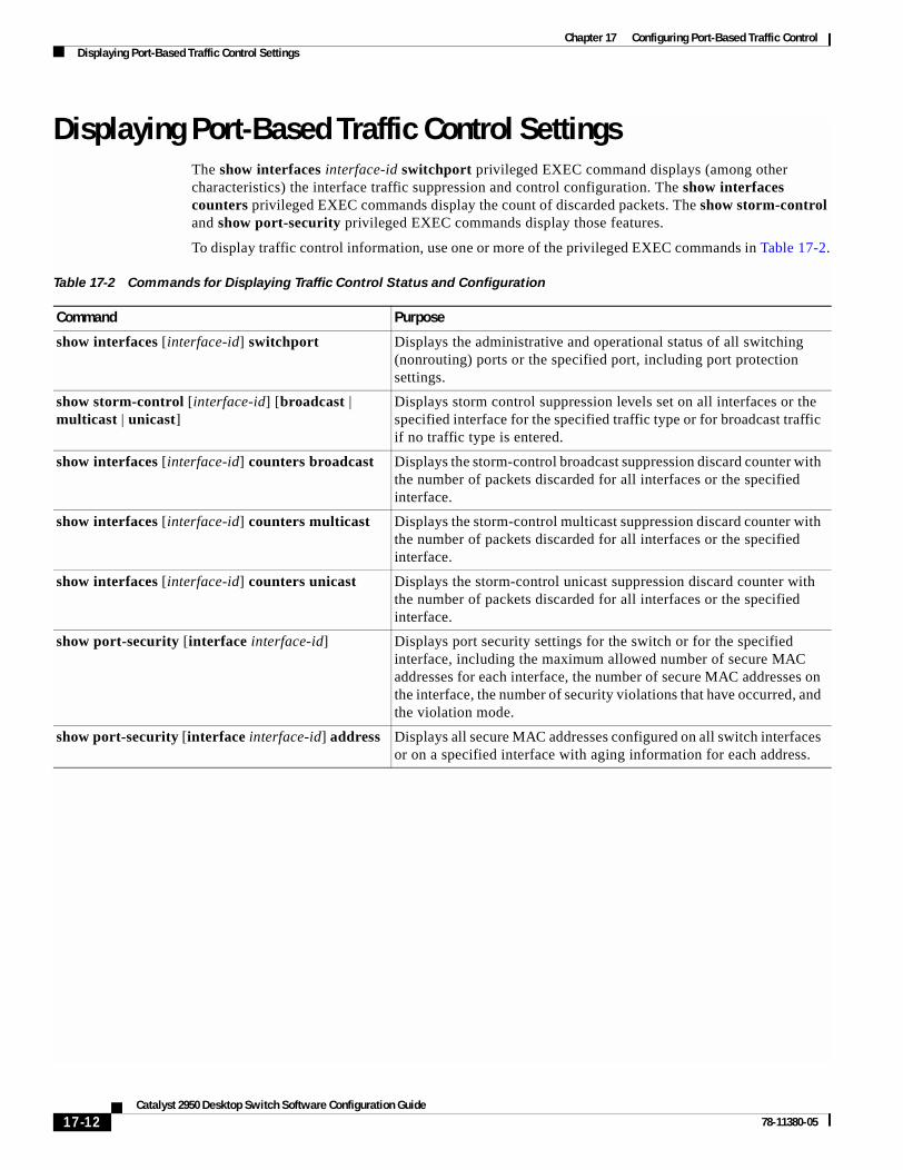
Chapter 17 Configuring Port-Based Traffic ControlDisplaying Port-Based Traffic Control Settings
Displaying Port-Based Traffic Control SettingsThe show interfaces interface-id switchport privileged EXEC command displays (among other characteristics) the interface traffic suppression and control configuration. The show interfaces counters privileged EXEC commands display the count of discarded packets. The show storm-control and show port-security privileged EXEC commands display those features.
To display traffic control information, use one or more of the privileged EXEC commands in Table 17-2.
Table 17-2 Commands for Displaying Traffic Control Status and Configuration
Command Purpose
show interfaces [interface-id] switchport Displays the administrative and operational status of all switching (nonrouting) ports or the specified port, including port protection settings.
show storm-control [interface-id] [broadcast | multicast | unicast]
Displays storm control suppression levels set on all interfaces or the specified interface for the specified traffic type or for broadcast traffic if no traffic type is entered.
show interfaces [interface-id] counters broadcast Displays the storm-control broadcast suppression discard counter with the number of packets discarded for all interfaces or the specified interface.
show interfaces [interface-id] counters multicast Displays the storm-control multicast suppression discard counter with the number of packets discarded for all interfaces or the specified interface.
show interfaces [interface-id] counters unicast Displays the storm-control unicast suppression discard counter with the number of packets discarded for all interfaces or the specified interface.
show port-security [interface interface-id] Displays port security settings for the switch or for the specified interface, including the maximum allowed number of secure MAC addresses for each interface, the number of secure MAC addresses on the interface, the number of security violations that have occurred, and the violation mode.
show port-security [interface interface-id] address Displays all secure MAC addresses configured on all switch interfaces or on a specified interface with aging information for each address.
17-12Catalyst 2950 Desktop Switch Software Configuration Guide
78-11380-05

Catalyst 2950 Deskto78-11380-05
C H A P T E R 18
Configuring UDLDThis chapter describes how to configure the UniDirectional Link Detection (UDLD) protocol on your switch.
Note For complete syntax and usage information for the commands used in this chapter, refer to the command reference for this release.
This chapter consists of these sections:
• Understanding UDLD, page 18-1
• Configuring UDLD, page 18-3
• Displaying UDLD Status, page 18-6
Understanding UDLDUDLD is a Layer 2 protocol that enables devices connected through fiber-optic or twisted-pair Ethernet cables to monitor the physical configuration of the cables and detect when a unidirectional link exists. All connected devices must support UDLD for the protocol to successfully identify and disable unidirectional links. When UDLD detects a unidirectional link, it administratively shuts down the affected port and alerts you. Unidirectional links can cause a variety of problems, including spanning-tree topology loops.
UDLD works with the Layer 1 mechanisms to determine the physical status of a link. At Layer 1, autonegotiation takes care of physical signaling and fault detection. UDLD performs tasks that autonegotiation cannot perform, such as detecting the identities of neighbors and shutting down misconnected interfaces. When you enable both autonegotiation and UDLD, Layer 1 and Layer 2 detections work together to prevent physical and logical unidirectional connections and the malfunctioning of other protocols.
A unidirectional link occurs whenever traffic sent by the local device is received by the neighbor but traffic from the neighbor is not received by the local device. If one of the fiber strands in a pair is disconnected, as long as autonegotiation is active, the link does not stay up. In this case, the logical link is undetermined, and UDLD does not take any action. If both fibers are working normally from a Layer 1 perspective, UDLD at Layer 2 determines whether those fibers are connected correctly and whether traffic is flowing bidirectionally between the correct neighbors. This check cannot be performed by autonegotiation because autonegotiation operates at Layer 1.
18-1p Switch Software Configuration Guide

Chapter 18 Configuring UDLDUnderstanding UDLD
UDLD operates by using two mechanisms:
• Neighbor database maintenance
UDLD learns about other UDLD-capable neighbors by periodically sending a hello packet (also called an advertisement or probe) on every active interface to keep each device informed about its neighbors.
When the switch receives a hello message, it caches the information until the age time (hold time or time-to-live) expires. If the switch receives a new hello message before an older cache entry ages, the switch replaces the older entry with the new one.
Whenever an interface is disabled and UDLD is running, whenever UDLD is disabled on an interface, or whenever the switch is reset, UDLD clears all existing cache entries for the interfaces affected by the configuration change. UDLD sends at least one message to inform the neighbors to flush the part of their caches affected by the status change. The message is intended to keep the caches synchronized.
• Event-driven detection and echoing
UDLD relies on echoing as its detection mechanism. Whenever a UDLD device learns about a new neighbor or receives a resynchronization request from an out-of-sync neighbor, it restarts the detection window on its side of the connection and sends echo messages in reply. Because this behavior is the same on all UDLD neighbors, the sender of the echoes expects to receive an echo in reply. If the detection window ends and no valid reply message is received, the link is considered unidirectional, and the interface is shut down.
Figure 18-1 shows an example of a unidirectional link condition.
Figure 18-1 UDLD Detection of a Unidirectional Link
TX
TX
RX
RX
Switch A
Switch B
Switch B successfullyreceives traffic from
Switch A on this port. However, Switch A does not receive trafficfrom Switch B on the same port. UDLDdetects the problem and disables the port.
4358
3
18-2Catalyst 2950 Desktop Switch Software Configuration Guide
78-11380-05

Chapter 18 Configuring UDLDConfiguring UDLD
Configuring UDLDThis section describes how to configure UDLD on your switch. It contains this configuration information:
• Default UDLD Configuration, page 18-3
• Enabling UDLD Globally, page 18-4
• Enabling UDLD on an Interface, page 18-4
• Resetting an Interface Shut Down by UDLD, page 18-5
Default UDLD ConfigurationTable 18-1 shows the default UDLD configuration.
A UDLD-capable interface also cannot detect a unidirectional link if it is connected to a UDLD-incapable port of another switch.
Table 18-1 Default UDLD Configuration
Feature Default Setting
UDLD global enable state Globally disabled
UDLD per-interface enable state for fiber-optic media Disabled on all Ethernet fiber-optic interfaces
UDLD per-interface enable state for twisted-pair (copper) media
Disabled on all Ethernet 10/100 and 1000BASE-TX interfaces
UDLD aggressive mode Disabled
18-3Catalyst 2950 Desktop Switch Software Configuration Guide
78-11380-05

Chapter 18 Configuring UDLDConfiguring UDLD
Enabling UDLD GloballyBeginning in privileged EXEC mode, follow these steps to enable UDLD in the aggressive or normal mode and to set the configurable message timer on all fiber-optic interfaces on the switch:
To disable UDLD globally, use the no udld enable global configuration command to disable normal mode UDLD on all fiber-optic ports. Use the no udld aggressive global configuration command to disable aggressive mode UDLD on all fiber-optic ports.
Enabling UDLD on an InterfaceBeginning in privileged EXEC mode, follow these steps to enable UDLD in the aggressive or normal mode on an interface:
Command Purpose
Step 1 configure terminal Enter global configuration mode.
Step 2 udld {aggressive | enable | message time message-timer-interval}
Specify the UDLD mode of operation:
• aggressive—Enables UDLD in aggressive mode on all fiber-optic interfaces. For details on the usage guidelines for the aggressive mode, refer to the command reference guide.
• enable—Enables UDLD in normal mode on all fiber-optic interfaces on the switch. UDLD is disabled by default.
An individual interface configuration overrides the setting of the udld enable global configuration command.
• message time message-timer-interval—Configures the period of time between UDLD probe messages on ports that are in the advertisement phase and are determined to be bidirectional. The range is from 7 to 90 seconds.
Note This command affects fiber-optic interfaces only. Use the udld interface configuration command to enable UDLD on other interface types. For more information, see the “Enabling UDLD on an Interface” section on page 18-4.
Step 3 end Return to privileged EXEC mode.
Step 4 show udld Verify your entries.
Step 5 copy running-config startup-config (Optional) Save your entries in the configuration file.
Command Purpose
Step 1 configure terminal Enter global configuration mode.
Step 2 interface interface-id Enter interface configuration mode, and specify the interface to be enabled for UDLD.
18-4Catalyst 2950 Desktop Switch Software Configuration Guide
78-11380-05

Chapter 18 Configuring UDLDConfiguring UDLD
To disable UDLD on a non-fiber-optic interface, use the no udld enable interface configuration command.
Note On fiber-optic interfaces, the no udld enable command reverts the interface configuration to the udld enable global configuration command setting.
To disable UDLD on a fiber-optic interface, use the udld disable command to revert to the udld enable global configuration command setting. This command is not supported on non-fiber-optic interfaces.
Resetting an Interface Shut Down by UDLDBeginning in privileged EXEC mode, follow these steps to reset all interfaces shut down by UDLD:
You can also bring up the interface by using these commands:
• The shutdown interface configuration command followed by the no shutdown interface configuration command restarts the disabled interface.
• The no udld enable global configuration command re-enables UDLD globally.
• The udld disable interface configuration command re-enables UDLD on the specified interface.
Step 3 udld {aggressive | enable} Specify the UDLD mode of operation:
• aggressive—Enables UDLD in aggressive mode on the specified interface. For details on the usage guidelines for the aggressive mode, refer to the command reference guide.
• enable—Enables UDLD in normal mode on the specified interface. UDLD is disabled by default.
On a fiber-optic interface, this command overrides the udld enable global configuration command setting.
Step 4 end Return to privileged EXEC mode.
Step 5 show udld interface-id Verify your entries.
Step 6 copy running-config startup-config (Optional) Save your entries in the configuration file.
Command Purpose
Command Purpose
Step 1 udld reset Reset all interfaces shut down by UDLD.
Step 2 show udld Verify your entries.
Step 3 copy running-config startup-config (Optional) Save your entries in the configuration file.
18-5Catalyst 2950 Desktop Switch Software Configuration Guide
78-11380-05

Chapter 18 Configuring UDLDDisplaying UDLD Status
Displaying UDLD StatusTo display the UDLD status for the specified interface or for all interfaces, use the show udld [interface-id] privileged EXEC command.
For detailed information about the fields in the display, refer to the command reference for this release.
18-6Catalyst 2950 Desktop Switch Software Configuration Guide
78-11380-05

Catalyst 2950 Deskto78-11380-05
C H A P T E R 19
Configuring CDPThis chapter describes how to configure Cisco Discovery Protocol (CDP) on your switch.
Note For complete syntax and usage information for the commands used in this chapter, refer to the command reference for this release and the Cisco IOS Configuration Fundamentals Command Reference for Release 12.1.
This chapter consists of these sections:
• Understanding CDP, page 19-1
• Configuring CDP, page 19-2
• Monitoring and Maintaining CDP, page 19-5
Understanding CDPCDP is a device discovery protocol that runs over Layer 2 (the data link layer) on all Cisco-manufactured devices (routers, bridges, access servers, and switches) and allows network management applications to discover Cisco devices that are neighbors of already known devices. With CDP, network management applications can learn the device type and the Simple Network Management Protocol (SNMP) agent address of neighboring devices running lower-layer, transparent protocols. This feature enables applications to send SNMP queries to neighboring devices.
CDP runs on all media that support Subnetwork Access Protocol (SNAP). Because CDP runs over the data-link layer only, two systems that support different network-layer protocols can learn about each other.
Each CDP-configured device sends periodic messages to a multicast address, advertising at least one address at which it can receive SNMP messages. The advertisements also contain time-to-live, or holdtime information, which is the length of time a receiving device holds CDP information before discarding it. Each device also listens to the messages sent by other devices to learn about neighboring devices.
On the switch, CDP enables the Cluster Management Suite to display a graphical view of the network. The switch uses CDP to find cluster candidates and maintain information about cluster members and other devices up to three cluster-enabled devices away from the command switch by default.
The switch supports CDP version 2.
19-1p Switch Software Configuration Guide

Chapter 19 Configuring CDPConfiguring CDP
Configuring CDPThese sections include CDP configuration information and procedures:
• Default CDP Configuration, page 19-2
• Configuring the CDP Characteristics, page 19-2
• Disabling and Enabling CDP, page 19-3
• Disabling and Enabling CDP on an Interface, page 19-4
Default CDP ConfigurationTable 19-1 shows the default CDP configuration.
Configuring the CDP CharacteristicsYou can configure the frequency of CDP updates, the amount of time to hold the information before discarding it, and whether or not to send version-2 advertisements.
Beginning in privileged EXEC mode, follow these steps to configure the CDP timer, holdtime, and advertisement type.
Note Steps 2 through 4 are all optional and can be performed in any order.
Table 19-1 Default CDP Configuration
Feature Default Setting
CDP global state Enabled
CDP interface state Enabled
CDP timer (packet update frequency) 60 seconds
CDP holdtime (before discarding) 180 seconds
CDP version-2 advertisements Enabled
Command Purpose
Step 1 configure terminal Enter global configuration mode.
Step 2 cdp timer seconds (Optional) Set the transmission frequency of CDP updates in seconds.
The range is from 5 to 254; the default is 60 seconds.
Step 3 cdp holdtime seconds (Optional) Specify the amount of time a receiving device should hold the information sent by your device before discarding it.
The range is from 10 to 255 seconds; the default is 180 seconds.
Step 4 cdp advertise-v2 (Optional) Configure CDP to send version-2 advertisements.
This is the default state.
Step 5 end Return to privileged EXEC mode.
19-2Catalyst 2950 Desktop Switch Software Configuration Guide
78-11380-05

Chapter 19 Configuring CDPConfiguring CDP
Use the no form of the CDP commands to return to the default settings.
This example shows how to configure and verify CDP characteristics.
Switch# configure terminalSwitch(config)# cdp timer 50Switch(config)# cdp holdtime 120Switch(config)# cdp advertise-v2Switch(config)# end
Switch# show cdp
Global CDP information: Sending CDP packets every 50 seconds Sending a holdtime value of 120 seconds Sending CDPv2 advertisements is enabled
For additional CDP show commands, see the “Monitoring and Maintaining CDP” section on page 19-5.
Disabling and Enabling CDPCDP is enabled by default.
Note Creating and maintaining switch clusters is based on the regular exchange of CDP messages. Disabling CDP can interrupt cluster discovery. For more information, see Chapter 6, “Clustering Switches.”
Beginning in privileged EXEC mode, follow these steps to disable the CDP device discovery capability:
Beginning in privileged EXEC mode, follow these steps to enable CDP when it has been disabled:
Step 6 show cdp Verify configuration by displaying global information about CDP on the device.
Step 7 copy running-config startup-config (Optional) Save your entries in the configuration file.
Command Purpose
Command Purpose
Step 1 configure terminal Enter global configuration mode.
Step 2 no cdp run Disable CDP.
Step 3 end Return to privileged EXEC mode.
Command Purpose
Step 1 configure terminal Enter global configuration mode.
Step 2 cdp run Enable CDP after disabling it.
Step 3 end Return to privileged EXEC mode.
19-3Catalyst 2950 Desktop Switch Software Configuration Guide
78-11380-05

Chapter 19 Configuring CDPConfiguring CDP
This example shows how to enable CDP if it has been disabled.
Switch# configure terminalSwitch(config)# cdp runSwitch(config)# end
Disabling and Enabling CDP on an InterfaceCDP is enabled by default on all supported interfaces to send and receive CDP information.
Beginning in privileged EXEC mode, follow these steps to disable CDP on an interface:
Beginning in privileged EXEC mode, follow these steps to enable CDP on an interface when it has been disabled:
This example shows how to enable CDP on an interface when it has been disabled.
Switch# configure terminalSwitch(config)# interface fastethernet0/5Switch(config-if)# cdp enableSwitch(config-if)# end
Command Purpose
Step 1 configure terminal Enter global configuration mode.
Step 2 interface interface-id Enter interface configuration mode, and enter the interface on which you are disabling CDP.
Step 3 no cdp enable Disable CDP on an interface.
Step 4 end Return to privileged EXEC mode.
Step 5 copy running-config startup-config (Optional) Save your entries in the configuration file.
Command Purpose
Step 1 configure terminal Enter global configuration mode.
Step 2 interface interface-id Enter interface configuration mode, and enter the interface on which you are enabling CDP.
Step 3 cdp enable Enable CDP on an interface after disabling it.
Step 4 end Return to privileged EXEC mode.
Step 5 copy running-config startup-config (Optional) Save your entries in the configuration file.
19-4Catalyst 2950 Desktop Switch Software Configuration Guide
78-11380-05

Chapter 19 Configuring CDPMonitoring and Maintaining CDP
Monitoring and Maintaining CDPTo monitor and maintain CDP on your device, perform one or more of these tasks, beginning in privileged EXEC mode.
This is an example of the output from the show cdp privileged EXEC commands:
Switch# show cdp
Global CDP information: Sending CDP packets every 50 seconds Sending a holdtime value of 120 seconds Sending CDPv2 advertisements is enabled
Command Description
clear cdp counters Reset the traffic counters to zero.
clear cdp table Delete the CDP table of information about neighbors.
show cdp Display global information, such as frequency of transmissions and the holdtime for packets being sent.
show cdp entry entry-name [protocol | version]
Display information about a specific neighbor.
You can enter an asterisk (*) to display all CDP neighbors, or you can enter the name of the neighbor about which you want information.
You can also limit the display to information about the protocols enabled on the specified neighbor or information about the version of software running on the device.
show cdp interface [type number] Display information about interfaces where CDP is enabled.
You can limit the display to the type of interface or the number of the interface about which you want information (for example, entering gigabitethernet 0/1 displays information only about Gigabit Ethernet port 1).
show cdp neighbors [type number] [detail]
Display information about neighbors, including device type, interface type and number, holdtime settings, capabilities, platform, and port ID.
You can limit the display to neighbors on a specific type or number of interface or expand the display to provide more detailed information.
show cdp traffic Display CDP counters, including the number of packets sent and received and checksum errors.
19-5Catalyst 2950 Desktop Switch Software Configuration Guide
78-11380-05

Chapter 19 Configuring CDPMonitoring and Maintaining CDP
19-6Catalyst 2950 Desktop Switch Software Configuration Guide
78-11380-05

Catalyst 2950 Deskto78-11380-05
C H A P T E R 20
Configuring SPAN and RSPANThis chapter describes how to configure Switched Port Analyzer (SPAN) and Remote SPAN (RSPAN) on your switch. To use the RSPAN feature described in this chapter, you must have the enhanced software image (EI) installed on your switch.
Note For complete syntax and usage information for the commands used in this chapter, refer to the command reference for this release.
This chapter consists of these sections:
• Understanding SPAN and RSPAN, page 20-1
• Configuring SPAN, page 20-7
• Configuring RSPAN, page 20-10
• Displaying SPAN and RSPAN Status, page 20-14
Understanding SPAN and RSPANYou can analyze network traffic passing through ports by using SPAN to send a copy of the traffic to another port on the switch that has been connected to a SwitchProbe device or other Remote Monitoring (RMON) probe. SPAN mirrors received or sent (or both) traffic on one or more source ports to a destination port for analysis.
For example, in Figure 20-1, all traffic on port 5 (the source port) is mirrored to port 10 (the destination port). A network analyzer on port 10 receives all network traffic from port 5 without being physically attached to port 5.
20-1p Switch Software Configuration Guide

Chapter 20 Configuring SPAN and RSPANUnderstanding SPAN and RSPAN
Figure 20-1 Example SPAN Configuration
Only traffic that enters or leaves source ports can be monitored by using SPAN.
RSPAN extends SPAN by enabling remote monitoring of multiple switches across your network. The traffic for each RSPAN session is carried over a user-specified RSPAN VLAN that is dedicated for that RSPAN session in all participating switches. The SPAN traffic from the sources is copied onto the RSPAN VLAN through a reflector port and then forwarded over trunk ports that are carrying the RSPAN VLAN to any RSPAN destination session monitoring the RSPAN VLAN, as shown in Figure 20-2.
Figure 20-2 Example of RSPAN Configuration
SPAN and RSPAN do not affect the switching of network traffic on source ports; a copy of the packets received or sent by the source interfaces are sent to the destination interface. Except for traffic that is required for the SPAN or RSPAN session, reflector ports and destination ports do not receive or forward traffic.
1 2 3 4 5 6 7 8 9 10 11 12Port 5 traffic mirroredon Port 10
32
1
45
6 78
911
12
10
Network analyzer 4358
0
Source switch Intermediate switch Destination switch
7472
7
RSPANsource port
RSPANdestination port
Reflectorport
RSPANVLAN
RSPANVLAN
20-2Catalyst 2950 Desktop Switch Software Configuration Guide
78-11380-05

Chapter 20 Configuring SPAN and RSPANUnderstanding SPAN and RSPAN
SPAN and RSPAN Concepts and TerminologyThis section describes concepts and terminology associated with SPAN and RSPAN configuration.
SPAN Session
A local SPAN session is an association of a destination port with source ports. You can monitor incoming or outgoing traffic on a series or range of ports.
An RSPAN session is an association of source ports across your network with an RSPAN VLAN. The destination source is the RSPAN VLAN.
SPAN sessions do not interfere with the normal operation of the switch. However, an oversubscribed SPAN destination, for example, a 10-Mbps port monitoring a 100-Mbps port, results in dropped or lost packets.
You can configure SPAN sessions on disabled ports; however, a SPAN session does not become active unless you enable the destination port and at least one source port for that session. The show monitor session session_number privileged EXEC command displays the operational status of a SPAN session.
A SPAN session remains inactive after system power-on until the destination port is operational.
Traffic Types
SPAN sessions include these traffic types:
• Receive (Rx) SPAN—The goal of receive (or ingress) SPAN is to monitor as much as possible all the packets received by the source interface. A copy of each packet received by the source is sent to the destination port for that SPAN session. You can monitor a series or range of ingress ports in a SPAN session.
At the destination port, if tagging is enabled, the packets appear with the 802.1Q header. If no tagging is specified, packets appear in the native format.
Packets that are modified because of quality of service (QoS)—for example, modified Differentiated Services Code Point (DSCP)—are copied with modification for Rx SPAN.
• Transmit (Tx) SPAN—The goal of transmit (or egress) SPAN is to monitor as much as possible all the packets sent by the source interface after all modification and processing is performed by the switch. A copy of each packet sent by the source is sent to the destination port for that SPAN session. The copy is provided after the packet is modified. You can monitor a range of egress ports in a SPAN session.
Packets that are modified because of QoS, the modified packet might not have the same DSCP (IP packet) or CoS (non-IP packet) as the SPAN source.
Some features that can cause a packet to be dropped during transmit processing might also affect the duplicated copy for SPAN. These features include IP standard and extended output ACLs on multicast packets, and egress QoS policing. In the case of output ACLs, if the SPAN source drops the packet, the SPAN destination would also drop the packet. If the source port is oversubscribed, the destination ports will have different dropping behavior.
• Both—In a SPAN session, you can monitor a series or range of ports for both received and sent packets.
20-3Catalyst 2950 Desktop Switch Software Configuration Guide
78-11380-05

Chapter 20 Configuring SPAN and RSPANUnderstanding SPAN and RSPAN
Source Port
A source port (also called a monitored port) is a switched port that you monitor for network traffic analysis. In a single local SPAN session or RSPAN source session, you can monitor source port traffic such as received (Rx), transmitted (Tx), or bidirectional (both). The switch supports any number of source ports (up to the maximum number of available ports on the switch).
A source port has these characteristics:
• It can be any port type (for example, EtherChannel, Fast Ethernet, Gigabit Ethernet, and so forth).
• It cannot be a destination port.
• Each source port can be configured with a direction (ingress, egress, or both) to monitor. For EtherChannel sources, the monitored direction would apply to all the physical ports in the group.
• Source ports can be in the same or different VLANs.
You can configure a trunk port as a source port. All VLANs active on the trunk are monitored.
Destination Port
Each local SPAN session or RSPAN destination session must have a destination port (also called a monitoring port) that receives a copy of traffic from the source port.
The destination port has these characteristics:
• It must reside on the same switch as the source port (for a local SPAN session).
• It can be any Ethernet physical port.
• It cannot be a source port or a reflector port.
• It cannot be an EtherChannel group or a VLAN.
• It can be a physical port that is assigned to an EtherChannel group, even if the EtherChannel group has been specified as a SPAN source. The port is removed from the group while it is configured as a SPAN destination port.
• When it is active, incoming traffic is disabled. The port does not transmit any traffic except that required for the SPAN session.
• It does not participate in spanning tree while the SPAN session is active.
• When it is a destination port, it does not participate in any of the Layer 2 protocols (STP, VTP, CDP, DTP, PagP).
• No address learning occurs on the destination port.
Reflector Port
The reflector port is the mechanism that copies packets onto an RSPAN VLAN. The reflector port forwards only the traffic from the RSPAN source session with which it is affiliated. Any device connected to a port set as a reflector port loses connectivity until the RSPAN source session is disabled.
The reflector port has these characteristics:
• It is a port set to loopback.
• It cannot be an EtherChannel group, it does not trunk, and it cannot do protocol filtering.
20-4Catalyst 2950 Desktop Switch Software Configuration Guide
78-11380-05

Chapter 20 Configuring SPAN and RSPANUnderstanding SPAN and RSPAN
• It can be a physical port that is assigned to an EtherChannel group, even if the EtherChannel group is specified as a SPAN source. The port is removed from the group while it is configured as a reflector port.
• A port used as a reflector port cannot be a SPAN source or destination port, nor can a port be a reflector port for more than one session at a time.
• It is invisible to all VLANs.
• The native VLAN for looped-back traffic on a reflector port is the RSPAN VLAN.
• The reflector port loops back untagged traffic to the switch. The traffic is then placed on the RSPAN VLAN and flooded to any trunk ports that carry the RSPAN VLAN.
• Spanning tree is automatically disabled on a reflector port.
If the bandwidth of the reflector port is not sufficient to handle the traffic from the corresponding source ports, the excess packets are dropped. A 10/100 port reflects at 100 Mbps. A Gigabit port reflects at 1 Gbps.
SPAN Traffic
You can use local SPAN to monitor all network traffic, including multicast and bridge protocol data unit (BPDU) packets, and Cisco Discovery Protocol (CDP), VLAN Trunk Protocol (VTP), Dynamic Trunking Protocol (DTP), Spanning Tree Protocol (STP), and Port Aggregation Protocol (PagP) packets. You cannot use RSPAN to monitor Layer 2 protocols. See the “RSPAN Configuration Guidelines” section on page 20-10 for more information.
In some SPAN configurations, multiple copies of the same source packet are sent to the SPAN destination port. For example, a bidirectional (both Rx and Tx) SPAN session is configured for the sources a1 Rx monitor and the a2 Rx and Tx monitor to destination port d1. If a packet enters the switch through a1 and is switched to a2, both incoming and outgoing packets are sent to destination port d1.
SPAN and RSPAN Interaction with Other FeaturesSPAN interacts with these features:
• Spanning Tree Protocol (STP)—A destination port or a reflector port does not participate in STP while its SPAN or RSPAN session is active. The destination or reflector port can participate in STP after the SPAN or RSPAN session is disabled. On a source port, SPAN does not affect the STP status. STP can be active on trunk ports carrying an RSPAN VLAN.
• Cisco Discovery Protocol (CDP)—A SPAN destination port does not participate in CDP while the SPAN session is active. After the SPAN session is disabled, the port again participates in CDP.
• VLAN Trunking Protocol (VTP)—You can use VTP to prune an RSPAN VLAN between switches.
• VLAN and trunking—You can modify VLAN membership or trunk settings for source, destination, or reflector ports at any time. However, changes in VLAN membership or trunk settings for a destination or reflector port do not take effect until you disable the SPAN or RSPAN session. Changes in VLAN membership or trunk settings for a source port immediately take effect, and the SPAN session automatically adjusts accordingly.
• EtherChannel—You can configure an EtherChannel group as a source port but not as a SPAN destination port. When a group is configured as a SPAN source, the entire group is monitored.
20-5Catalyst 2950 Desktop Switch Software Configuration Guide
78-11380-05

Chapter 20 Configuring SPAN and RSPANUnderstanding SPAN and RSPAN
If a port is added to a monitored EtherChannel group, the new port is added to the SPAN source port list. If a port is removed from a monitored EtherChannel group, it is automatically removed from the source port list. If the port is the only port in the EtherChannel group, the EtherChannel group is removed from SPAN.
If a physical port that belongs to an EtherChannel group is configured as a SPAN source, destination, or reflector port, it is removed from the group. After the port is removed from the SPAN session, it rejoins the EtherChannel group. Ports removed from an EtherChannel group remain members of the group, but they are in the down or standalone state.
If a physical port that belongs to an EtherChannel group is a destination or reflector port and the EtherChannel group is a source, the port is removed from the EtherChannel group and from the list of monitored ports.
• QoS—For ingress monitoring, the packets sent to the SPAN destination port might be different from the packets actually received at the SPAN source port because the packets are forwarded after ingress QoS classification and policing. The packet DSCP might not be the same as the received packet.
• Multicast traffic can be monitored. For egress and ingress port monitoring, only a single unedited packet is sent to the SPAN destination port. It does not reflect the number of times the multicast packet is sent.
• A secure port cannot be a SPAN destination port.
SPAN and RSPAN Session LimitsYou can configure (and store in NVRAM) one local SPAN session or multiple RSPAN sessions on a switch. The number of active sessions and combinations are subject to these restrictions:
• SPAN or RSPAN source (rx, tx, both): 1 active session limit. (SPAN and RSPAN are mutually exclusive on a source switch).
• RSPAN source sessions have one destination per session with an RSPAN VLAN associated for that session.
• Each RSPAN destination session has one or more destination interfaces for each RSPAN VLAN that they support.
• RSPAN destination sessions are limited to two, or one if a local SPAN or a source RSPAN session is configured on the same switch.
Default SPAN and RSPAN ConfigurationTable 20-1 shows the default SPAN and RSPAN configuration.
Table 20-1 Default SPAN and RSPAN Configuration
Feature Default Setting
SPAN state Disabled.
Source port traffic to monitor Both received and sent traffic (both).
Encapsulation type (destination port) Native form (no encapsulation type header).
20-6Catalyst 2950 Desktop Switch Software Configuration Guide
78-11380-05

Chapter 20 Configuring SPAN and RSPANConfiguring SPAN
Configuring SPANThis section describes how to configure SPAN on your switch. It contains this configuration information:
• SPAN Configuration Guidelines, page 20-7
• Creating a SPAN Session and Specifying Ports to Monitor, page 20-7
• Removing Ports from a SPAN Session, page 20-9
SPAN Configuration GuidelinesFollow these guidelines when configuring SPAN:
• SPAN sessions can coexist with RSPAN sessions within the limits described in the “SPAN and RSPAN Session Limits” section on page 20-6.
• The destination port cannot be a source port; a source port cannot be a destination port.
• You can have only one destination port.
• An EtherChannel port can be a SPAN source port; it cannot be a SPAN destination port.
• For SPAN source ports, you can monitor sent and received traffic for a single port or for a series or range of ports.
• When you configure a switch port as a SPAN destination port, it is no longer a normal switch port; only monitored traffic passes through the SPAN destination port.
• You can configure a disabled port to be a source or destination port, but the SPAN function does not start until the destination port and at least one source port is enabled.
• A SPAN destination port never participates in any VLAN spanning tree. SPAN does include BPDUs in the monitored traffic, so any spanning-tree BPDUs received on the SPAN destination port for a SPAN session were copied from the SPAN source ports.
• When SPAN is enabled, configuration changes have these results:
– If you change the VLAN configuration of a destination port, the change is not effective until SPAN is disabled.
– If you disable all source ports or the destination port, the SPAN function stops until both a source and the destination port are enabled.
Creating a SPAN Session and Specifying Ports to MonitorBeginning in privileged EXEC mode, follow these steps to create a SPAN session and specify the source (monitored) and destination (monitoring) ports:
Command Purpose
Step 1 configure terminal Enter global configuration mode.
Step 2 no monitor session {session_number | all | local | remote}
Clear any existing SPAN configuration for the session.
For session_number, specify 1.
Specify all to remove all SPAN sessions, local to remove all local sessions, or remote to remove all remote SPAN sessions.
20-7Catalyst 2950 Desktop Switch Software Configuration Guide
78-11380-05

Chapter 20 Configuring SPAN and RSPANConfiguring SPAN
This example shows how to set up a SPAN session, session 1, for monitoring source port traffic to a destination port. First, any existing SPAN configuration for session 1 is cleared, and then bidirectional traffic is mirrored from source port 1 to destination port 10.
Switch(config)# no monitor session 1Switch(config)# monitor session 1 source interface fastEthernet0/1Switch(config)# monitor session 1 destination interface fastEthernet0/10 encapsulation dot1qSwitch(config)# end
Step 3 monitor session session_number source interface interface-id [, | -] [both | rx | tx]
Specify the SPAN session and the source port (monitored port).
For session_number, specify 1.
For interface-id, specify the source port to monitor. Valid interfaces include physical interfaces and port-channel logical interfaces (port-channel port-channel-number).
(Optional) [, | -] Specify a series or range of interfaces. Enter a space after the comma; enter a space before and after the hyphen.
(Optional) Specify the direction of traffic to monitor. If you do not specify a traffic direction, the source interface sends both sent and received traffic.
• both—Monitor both received and sent traffic.
• rx—Monitor received traffic.
• tx—Monitor sent traffic.
Step 4 monitor session session_number destination interface interface-id [encapsulation {dot1q}]
Specify the SPAN session and the destination port (monitoring port).
For session_number, specify 1.
For interface-id, specify the destination port. Valid interfaces include physical interfaces.
(Optional) Specify the encapsulation header for outgoing packets. If not specified, packets are sent in native form.
• dot1q—Use 802.1Q encapsulation.
Step 5 end Return to privileged EXEC mode.
Step 6 show monitor [session session_number] Verify your entries.
Step 7 copy running-config startup-config (Optional) Save your entries in the configuration file.
Command Purpose
20-8Catalyst 2950 Desktop Switch Software Configuration Guide
78-11380-05

Chapter 20 Configuring SPAN and RSPANConfiguring SPAN
Removing Ports from a SPAN SessionBeginning in privileged EXEC mode, follow these steps to remove a port as a SPAN source for a session:
To remove a source or destination port from the SPAN session, use the no monitor session session_number source interface interface-id global configuration command or the no monitor session session_number destination interface interface-id global configuration command. To change the encapsulation type back to the default (native), use the monitor session session_number destination interface interface-id without the encapsulation keyword.
This example shows how to remove port 1 as a SPAN source for SPAN session 1:
Switch(config)# no monitor session 1 source interface fastEthernet0/1Switch(config)# end
This example shows how to disable received traffic monitoring on port 1, which was configured for bidirectional monitoring:
Switch(config)# no monitor session 1 source interface fastEthernet0/1 rx
The monitoring of traffic received on port 1 is disabled, but traffic sent from this port continues to be monitored.
Command Purpose
Step 1 configure terminal Enter global configuration mode.
Step 2 no monitor session session_number source interface interface-id [, | -] [both | rx | tx]
Specify the characteristics of the source port (monitored port) and SPAN session to remove.
For session, specify 1.
For interface-id, specify the source port to no longer monitor. Valid interfaces include physical interfaces and port-channel logical interfaces (port-channel port-channel-number).
(Optional) Use [, | -] to specify a series or range of interfaces if they were configured. This option is valid when monitoring only received traffic. Enter a space after the comma; enter a space before and after the hyphen.
(Optional) Specify the direction of traffic (both, rx, or tx) to no longer monitor. If you do not specify a traffic direction, both transmit and receive are disabled.
Step 3 end Return to privileged EXEC mode.
Step 4 show monitor [session session_number] Verify your entries.
Step 5 copy running-config startup-config (Optional) Save your entries in the configuration file.
20-9Catalyst 2950 Desktop Switch Software Configuration Guide
78-11380-05

Chapter 20 Configuring SPAN and RSPANConfiguring RSPAN
Configuring RSPANThis section describes how to configure RSPAN on your switch. It contains this configuration information:
• RSPAN Configuration Guidelines, page 20-10
• Creating an RSPAN Session, page 20-11
• Creating an RSPAN Destination Session, page 20-12
• Removing Ports from an RSPAN Session, page 20-13
RSPAN Configuration GuidelinesTo use the RSPAN feature described in this section, you must have the EI installed on your switch. Follow these guidelines when configuring RSPAN:
• All the items in the “SPAN Configuration Guidelines” section on page 20-7 apply to RSPAN.
Note As RSPAN VLANs have special properties, you should reserve a few VLANs across your network for use as RSPAN VLANs; do not assign access ports to these VLANs.
• RSPAN sessions can coexist with SPAN sessions within the limits described in the “SPAN and RSPAN Session Limits” section on page 20-6.
• For RSPAN configuration, you can distribute the source ports and the destination ports across multiple switches in your network.
• A port cannot serve as an RSPAN source port or RSPAN destination port while designated as an RSPAN reflector port.
• When you configure a switch port as a reflector port, it is no longer a normal switch port; only looped-back traffic passes through the reflector port.
• RSPAN does not support BPDU packet monitoring or other Layer 2 switch protocols.
• In a network consisting of only Catalyst 2950 switches, you must use a unique RSPAN VLAN session on each source switch. If more than one source switch uses the same RSPAN VLAN, the switches are limited to act only as source switches to ensure the delivery of all monitored traffic to the destination switch.
• You can configure any VLAN as an RSPAN VLAN as long as these conditions are met:
– The RSPAN VLAN is not configured as a native VLAN.
– Extended range RSPAN VLANs will not be propagated to other switches using VTP.
– No access port is configured in the RSPAN VLAN.
– All participating switches support RSPAN.
20-10Catalyst 2950 Desktop Switch Software Configuration Guide
78-11380-05

Chapter 20 Configuring SPAN and RSPANConfiguring RSPAN
• You should create an RSPAN VLAN before configuring an RSPAN source or destination session.
• If you enable VTP and VTP pruning, RSPAN traffic is pruned in the trunks to prevent the unwanted flooding of RSPAN traffic across the network for VLAN-IDs that are lower than 1005.
Creating an RSPAN SessionFirst create an RSPAN VLAN that does not exist for the RSPAN session in any of the switches that will participate in RSPAN. With VTP enabled in the network, you can create the RSPAN VLAN in one switch, and VTP propagates it to the other switches in the VTP domain for VLAN-IDs that are lower than 1005.
Use VTP pruning to get efficient flow of RSPAN traffic, or manually delete the RSPAN VLAN from all trunks that do not need to carry the RSPAN traffic.
After creating the RSPAN VLAN, begin in privileged EXEC mode, and follow these steps to start an RSPAN source session and to specify the source (monitored) ports and the destination RSPAN VLAN.
Command Purpose
Step 1 configure terminal Enter global configuration mode.
Step 2 no monitor session {session_number | all | local | remote}
Clear any existing RSPAN configuration for the session.
For session_number, specify the session number identified with this RSPAN session.
Specify all to remove all RSPAN sessions, local to remove all local sessions, or remote to remove all remote SPAN sessions.
Step 3 monitor session session_number source interface interface-id [, | -] [both | rx | tx]
Specify the RSPAN session and the source port (monitored port).
For session_number, specify the session number identified with this RSPAN session.
For interface-id, specify the source port to monitor. Valid interfaces include physical interfaces and port-channel logical interfaces (port-channel port-channel-number).
(Optional) [, | -] Specify a series or range of interfaces. Enter a space after the comma; enter a space before and after the hyphen.
(Optional) Specify the direction of traffic to monitor. If you do not specify a traffic direction, the source interface sends both sent and received traffic.
• both—Monitor both received and sent traffic.
• rx—Monitor received traffic.
• tx—Monitor sent traffic.
20-11Catalyst 2950 Desktop Switch Software Configuration Guide
78-11380-05

Chapter 20 Configuring SPAN and RSPANConfiguring RSPAN
This example shows how to clear any existing RSPAN configuration for session 1, configure RSPAN session 1 to monitor multiple source interfaces, and configure the destination RSPAN VLAN and the reflector-port.
Switch(config)# no monitor session 1Switch(config)# monitor session 1 source interface fastEthernet0/10 txSwitch(config)# monitor session 1 source interface fastEthernet0/2 rxSwitch(config)# monitor session 1 source interface fastEthernet0/3 rxSwitch(config)# monitor session 1 source interface port-channel 102 rxSwitch(config)# monitor session 1 destination remote vlan 901 reflector-port fastEthernet0/1Switch(config)# end
Creating an RSPAN Destination SessionBeginning in privileged EXEC mode, follow these steps to create an RSPAN destination session and to specify the source RSPAN VLAN and the destination port:
Step 4 monitor session session_number destination remote vlan vlan-id reflector-port interface
Specify the RSPAN session, the destination remote VLAN, and the reflector port.
For session_number, enter the session number identified with this RSPAN session.
For vlan-id, specify the RSPAN VLAN to carry the monitored traffic to the destination port.
For interface, specify the interface that will flood the RSPAN traffic onto the RSPAN VLAN.
Step 5 end Return to privileged EXEC mode.
Step 6 show monitor [session session_number] Verify your entries.
Step 7 copy running-config startup-config (Optional) Save your entries in the configuration file.
Command Purpose
Command Purpose
Step 1 configure terminal Enter global configuration mode.
Step 2 monitor session session_number source remote vlan vlan-id
Specify the RSPAN session and the source RSPAN VLAN.
For session_number, specify the session number identified with this RSPAN session.
For vlan-id, specify the source RSPAN VLAN to monitor.
Step 3 monitor session session_number destination interface interface-id [encapsulation {dot1q}]
Specify the RSPAN session and the destination interface.
For session_number, specify the session number identified with this RSPAN session.
For interface-id, specify the destination interface.
(Optional) Specify the encapsulation header for outgoing packets. If not specified, packets are sent in native form.
• dot1q—Use 802.1Q encapsulation.
Step 4 end Return to privileged EXEC mode.
20-12Catalyst 2950 Desktop Switch Software Configuration Guide
78-11380-05

Chapter 20 Configuring SPAN and RSPANConfiguring RSPAN
This example shows how to configure VLAN 901 as the source remote VLAN and port 5 as the destination interface:
Switch(config)# monitor session 1 source remote vlan 901Switch(config)# monitor session 1 destination interface fastEthernet0/5Switch(config)# end
Removing Ports from an RSPAN SessionBeginning in privileged EXEC mode, follow these steps to remove a port as an RSPAN source for a session:
This example shows how to remove port 1 as an RSPAN source for RSPAN session 1:
Switch(config)# no monitor session 1 source interface fastEthernet0/1Switch(config)# end
This example shows how to disable received traffic monitoring on port 1, which was configured for bidirectional monitoring:
Switch(config)# no monitor session 1 source interface fastEthernet0/1 rx
The monitoring of traffic received on port 1 is disabled, but traffic sent from this port continues to be monitored.
Step 5 show monitor [session session_number] Verify your entries.
Step 6 copy running-config startup-config (Optional) Save your entries in the configuration file.
Command Purpose
Command Purpose
Step 1 configure terminal Enter global configuration mode.
Step 2 no monitor session session_number source interface interface-id [, | -] [both | rx | tx]
Specify the characteristics of the RSPAN source port (monitored port) to remove.
For session_number, specify the session number identified with this RSPAN session.
For interface-id, specify the source port to no longer monitor. Valid interfaces include physical interfaces and port-channel logical interfaces (port-channel port-channel-number).
(Optional) Use [, | -] to specify a series or range of interfaces if they were configured. Enter a space after the comma; enter a space before and after the hyphen.
(Optional) Specify the direction of traffic (both, rx, or tx) to no longer monitor. If you do not specify a traffic direction, both transmit and receive are disabled.
Step 3 end Return to privileged EXEC mode.
Step 4 show monitor [session session_number] Verify your entries.
Step 5 copy running-config startup-config (Optional) Save your entries in the configuration file.
20-13Catalyst 2950 Desktop Switch Software Configuration Guide
78-11380-05

Chapter 20 Configuring SPAN and RSPANDisplaying SPAN and RSPAN Status
Displaying SPAN and RSPAN StatusTo display the status of the current SPAN or RSPAN configuration, use the show monitor privileged EXEC command.
This is an example of output for the show monitor privileged EXEC command for RSPAN source session 1:
Switch# show monitor session 1Session 1---------Type: Remote Source SessionSource Ports: RX Only: Fa0/3 TX Only: None Both: None Source VLANs: RX Only: None TX Only: None Both: NoneSource RSPAN VLAN: NoneDestination Ports: None
Encapsulation: NativeReflector Port: Fa0/4Filter VLANs: NoneDest RSPAN VLAN: 901
20-14Catalyst 2950 Desktop Switch Software Configuration Guide
78-11380-05

Catalyst 2950 Deskto78-11380-05
C H A P T E R 21
Configuring RMONThis chapter describes how to configure Remote Network Monitoring (RMON) on your switch. RMON is a standard monitoring specification that defines a set of statistics and functions that can be exchanged between RMON-compliant console systems and network probes. RMON provides you with comprehensive network-fault diagnosis, planning, and performance-tuning information.
Note For complete syntax and usage information for the commands used in this chapter, refer to the Cisco IOS Configuration Fundamentals Command Reference for Release 12.1.
This chapter consists of these sections:
• Understanding RMON, page 21-1
• Configuring RMON, page 21-2
• Displaying RMON Status, page 21-6
Understanding RMONRMON is an Internet Engineering Task Force (IETF) standard monitoring specification that allows various network agents and console systems to exchange network monitoring data. You can use the RMON feature with the Simple Network Management Protocol (SNMP) agent in the switch to monitor all the traffic flowing among switches on all connected LAN segments.
21-1p Switch Software Configuration Guide

Chapter 21 Configuring RMONConfiguring RMON
Figure 21-1 Remote Monitoring Example
The switch supports these RMON groups (defined in RFC 1757):
• Statistics (RMON group 1)—Collects Ethernet, Fast Ethernet, and Gigabit Ethernet statistics on an interface.
• History (RMON group 2)—Collects a history group of statistics on Ethernet, Fast Ethernet, and Gigabit Ethernet interfaces for a specified polling interval.
• Alarm (RMON group 3)—Monitors a specific management information base (MIB) object for a specified interval, triggers an alarm at a specified value (rising threshold), and resets the alarm at another value (falling threshold). Alarms can be used with events; the alarm triggers an event, which can generate a log entry or an SNMP trap.
• Event (RMON group 9)—Determines the action to take when an event is triggered by an alarm. The action can be to generate a log entry or an SNMP trap.
Because switches supported by this IOS release use hardware counters for RMON data processing, the monitoring is more efficient, and little processing power is required.
Configuring RMONThis section describes how to configure RMON on your switch. It contains this configuration information:
• Default RMON Configuration, page 21-3
• Configuring RMON Alarms and Events, page 21-3
• Configuring RMON Collection on an Interface, page 21-5
Catalyst 3550 switchRMON alarms and events
configured. SNMP configured.
Catalyst 2950switch
RMON historyand statistic
collection enabled.
Workstations 7460
2
Catalyst 3550switch
Workstations
Network management station withgeneric RMON console application
21-2Catalyst 2950 Desktop Switch Software Configuration Guide
78-11380-05

Chapter 21 Configuring RMONConfiguring RMON
Default RMON ConfigurationRMON is disabled by default; no alarms or events are configured.
Only RMON 1 is supported on the switch.
Configuring RMON Alarms and EventsYou can configure your switch for RMON by using the command-line interface (CLI) or an SNMP-compatible network management station. We recommend that you use a generic RMON console application on the network management station (NMS) to take advantage of RMON’s network management capabilities. You must also configure SNMP on the switch to access RMON MIB objects. For more information, see Chapter 23, “Configuring SNMP.”
Beginning in privileged EXEC mode, follow these steps to enable RMON alarms and events:
Command Purpose
Step 1 configure terminal Enter global configuration mode.
Step 2 rmon alarm number variable interval {absolute | delta} rising-threshold value [event-number] falling-threshold value [event-number] [owner string]
Set an alarm on a MIB object.
• For number, specify the alarm number. The range is 1 to 65535.
• For variable, specify the MIB object to monitor.
• For interval, specify the time in seconds the alarm monitors the MIB variable. The range is 1 to 4294967295 seconds.
• Specify the absolute keyword to test each MIB variable directly; specify the delta keyword to test the change between samples of a MIB variable.
• For value, specify a number at which the alarm is triggered and one for when the alarm is reset. The range for the rising threshold and falling threshold values is -2147483648 to 2147483647.
• (Optional) For event-number, specify the event number to trigger when the rising or falling threshold exceeds its limit.
• (Optional) For owner string, specify the owner of the alarm.
21-3Catalyst 2950 Desktop Switch Software Configuration Guide
78-11380-05

Chapter 21 Configuring RMONConfiguring RMON
To disable an alarm, use the no rmon alarm number global configuration command on each alarm you configured. You cannot disable at once all the alarms that you configured. To disable an event, use the no rmon event number global configuration command. To learn more about alarms and events and how they interact with each other, refer to RFC 1757.
You can set an alarm on any MIB object. The following example configures RMON alarm number 10 by using the rmon alarm command. The alarm monitors the MIB variable ifEntry.20.1 once every 20 seconds until the alarm is disabled and checks the change in the variable’s rise or fall. If the ifEntry.20.1 value shows a MIB counter increase of 15 or more, such as from 100000 to 100015, the alarm is triggered. The alarm in turn triggers event number 1, which is configured with the rmon event command. Possible events can include a log entry or an SNMP trap. If the ifEntry.20.1 value changes by 0, the alarm is reset and can be triggered again.
Switch(config)# rmon alarm 10 ifEntry.20.1 20 delta rising-threshold 15 1 falling-threshold 0 owner jjohnson
The following example creates RMON event number 1 by using the rmon event command. The event is defined as High ifOutErrors and generates a log entry when the event is triggered by the alarm. The user jjones owns the row that is created in the event table by this command. This example also generates an SNMP trap when the event is triggered.
Switch(config)# rmon event 1 log trap eventtrap description "High ifOutErrors" owner jjones
Step 3 rmon event number [description string] [log] [owner string] [trap community]
Add an event in the RMON event table that is associated with an RMON event number.
• For number, assign an event number. The range is 1 to 65535.
• (Optional) For description string, specify a description of the event.
• (Optional) Use the log keyword to generate an RMON log entry when the event is triggered.
• (Optional) For owner string, specify the owner of this event.
• (Optional) For community, enter the SNMP community string used for this trap.
Step 4 end Return to privileged EXEC mode.
Step 5 show running-config Verify your entries.
Step 6 copy running-config startup-config (Optional) Save your entries in the configuration file.
Command Purpose
21-4Catalyst 2950 Desktop Switch Software Configuration Guide
78-11380-05

Chapter 21 Configuring RMONConfiguring RMON
Configuring RMON Collection on an InterfaceYou must first configure RMON alarms and events to display collection information.
Beginning in privileged EXEC mode, follow these steps to collect group history statistics on an interface:
To disable history collection, use the no rmon collection history index interface configuration command.
Beginning in privileged EXEC mode, follow these steps to collect group Ethernet statistics on an interface:
Command Purpose
Step 1 configure terminal Enter global configuration mode.
Step 2 interface interface-id Enter interface configuration mode, and specify the interface on which to collect history.
Step 3 rmon collection history index[buckets bucket-number] [interval seconds] [owner ownername]
Enable history collection for the specified number of buckets and time period.
• For index, identify the RMON group of statistics The range is 1 to 65535.
• (Optional) For buckets bucket-number, specify the maximum number of buckets desired for the RMON collection history group of statistics. The range is 1 to 65535. The default is 50 buckets.
• (Optional) For interval seconds, specify the number of seconds in each polling cycle.
• (Optional) For owner ownername, enter the name of the owner of the RMON group of statistics.
Step 4 end Return to privileged EXEC mode.
Step 5 show running-config Verify your entries.
Step 6 show rmon history Display the contents of the switch history table.
Step 7 copy running-config startup-config (Optional) Save your entries in the configuration file.
Command Purpose
Step 1 configure terminal Enter global configuration mode.
Step 2 interface interface-id Enter interface configuration mode, and specify the interface on which to collect statistics.
Step 3 rmon collection stats index [owner ownername] Enable RMON statistic collection on the interface.
• For index, specify the RMON group of statistics. The range is from 1 to 65535.
• (Optional) For owner ownername, enter the name of the owner of the RMON group of statistics.
Step 4 end Return to privileged EXEC mode.
Step 5 show running-config Verify your entries.
21-5Catalyst 2950 Desktop Switch Software Configuration Guide
78-11380-05
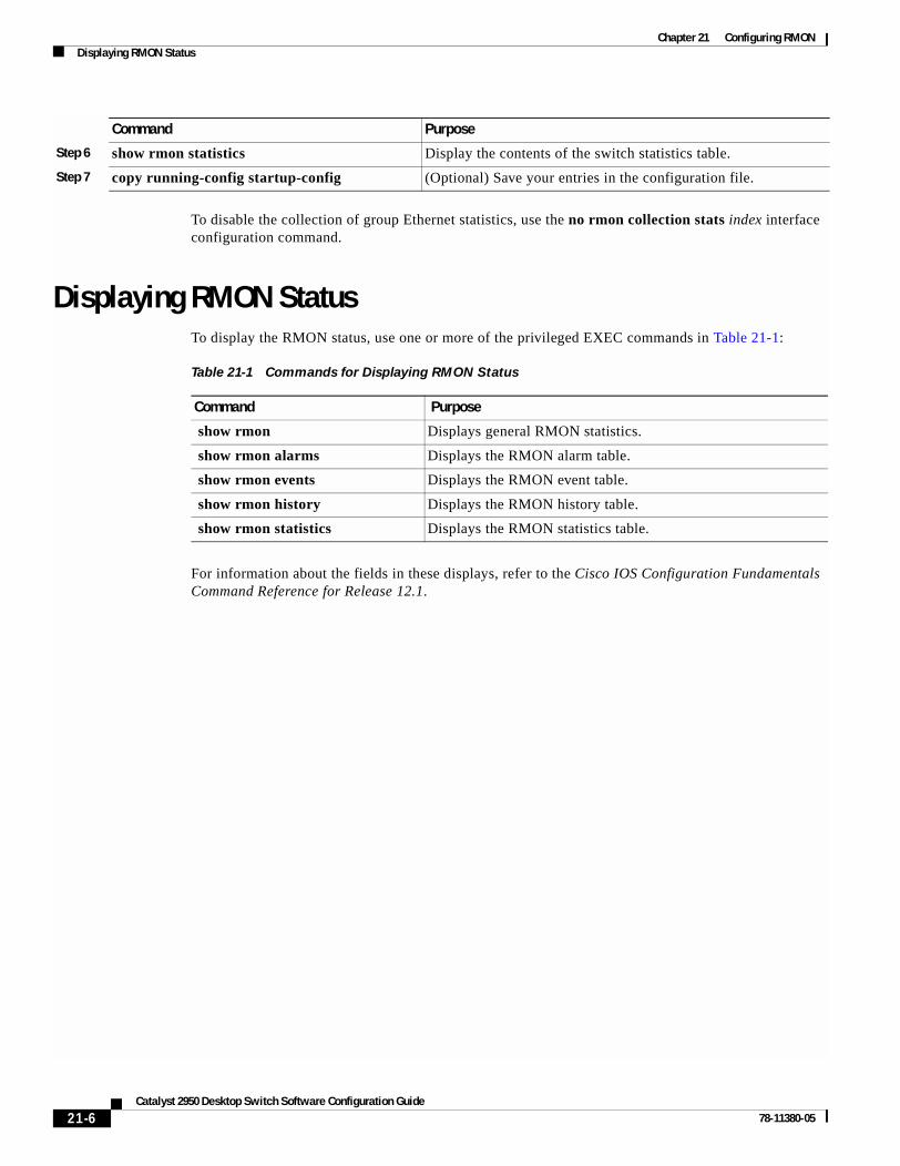
Chapter 21 Configuring RMONDisplaying RMON Status
To disable the collection of group Ethernet statistics, use the no rmon collection stats index interface configuration command.
Displaying RMON StatusTo display the RMON status, use one or more of the privileged EXEC commands in Table 21-1:
For information about the fields in these displays, refer to the Cisco IOS Configuration Fundamentals Command Reference for Release 12.1.
Step 6 show rmon statistics Display the contents of the switch statistics table.
Step 7 copy running-config startup-config (Optional) Save your entries in the configuration file.
Command Purpose
Table 21-1 Commands for Displaying RMON Status
Command Purpose
show rmon Displays general RMON statistics.
show rmon alarms Displays the RMON alarm table.
show rmon events Displays the RMON event table.
show rmon history Displays the RMON history table.
show rmon statistics Displays the RMON statistics table.
21-6Catalyst 2950 Desktop Switch Software Configuration Guide
78-11380-05

Catalyst 2950 Deskto78-11380-05
C H A P T E R 22
Configuring System Message LoggingThis chapter describes how to configure system message logging on your switch.
Note For complete syntax and usage information for the commands used in this chapter, refer to the Cisco IOS Configuration Fundamentals Command Reference for Release 12.1.
This chapter consists of these sections:
• Understanding System Message Logging, page 22-1
• Configuring System Message Logging, page 22-2
• Displaying the Logging Configuration, page 22-12
Understanding System Message LoggingBy default, a switch sends the output from system messages and debug privileged EXEC commands to a logging process. The logging process controls the distribution of logging messages to various destinations, such as the logging buffer, terminal lines, or a UNIX syslog server, depending on your configuration. The process also sends messages to the console.
Note The syslog format is compatible with 4.3 BSD UNIX.
When the logging process is disabled, messages are sent only to the console. The messages are sent as they are generated, so message and debug output are interspersed with prompts or output from other commands. Messages are displayed on the console after the process that generated them has finished.
You can set the severity level of the messages to control the type of messages displayed on the console and each of the destinations. You can timestamp log messages or set the syslog source address to enhance real-time debugging and management. For information on possible messages, refer to the system message guide for this release.
You can access logged system messages by using the switch command-line interface (CLI) or by saving them to a properly configured syslog server. The switch software saves syslog messages in an internal buffer. You can remotely monitor system messages by accessing the switch through Telnet, through the console port, or by viewing the logs on a syslog server.
22-1p Switch Software Configuration Guide

Chapter 22 Configuring System Message LoggingConfiguring System Message Logging
Configuring System Message LoggingThese sections describe how to configure system message logging:
• System Log Message Format, page 22-2
• Default System Message Logging Configuration, page 22-3
• Disabling and Enabling Message Logging, page 22-4
• Setting the Message Display Destination Device, page 22-4
• Synchronizing Log Messages, page 22-6
• Enabling and Disabling Timestamps on Log Messages, page 22-7
• Enabling and Disabling Sequence Numbers in Log Messages, page 22-8
• Defining the Message Severity Level, page 22-8
• Limiting Syslog Messages Sent to the History Table and to SNMP, page 22-10
• Configuring UNIX Syslog Servers, page 22-10
System Log Message FormatSystem log messages can contain up to 80 characters and a percent sign (%), which follows the optional sequence number or timestamp information, if configured. Messages are displayed in this format:
seq no:timestamp: %facility-severity-MNEMONIC:description
The part of the message preceding the percent sign depends on the setting of the service sequence-numbers, service timestamps log datetime, service timestamps log datetime [localtime] [msec] [show-timezone], or service timestamps log uptime global configuration command.
Table 22-1 describes the elements of syslog messages.
Table 22-1 System Log Message Elements
Element Description
seq no: Stamps log messages with a sequence number only if the service sequence-numbers global configuration command is configured.
For more information, see the “Enabling and Disabling Sequence Numbers in Log Messages” section on page 22-8.
timestamp formats:
mm/dd hh:mm:ss
or
hh:mm:ss (short uptime)
or
d h (long uptime)
Date and time of the message or event. This information appears only if the service timestamps log [datetime | log] global configuration command is configured.
For more information, see the “Enabling and Disabling Timestamps on Log Messages” section on page 22-7.
facility The facility to which the message refers (for example, SNMP, SYS, and so forth). For a list of supported facilities, see Table 22-4 on page 22-12.
severity Single-digit code from 0 to 7 that is the severity of the message. For a description of the severity levels, see Table 22-3 on page 22-9.
22-2Catalyst 2950 Desktop Switch Software Configuration Guide
78-11380-05

Chapter 22 Configuring System Message LoggingConfiguring System Message Logging
This example shows a partial switch system message:
00:00:46: %LINK-3-UPDOWN: Interface Port-channel1, changed state to up00:00:47: %LINK-3-UPDOWN: Interface GigabitEthernet0/1, changed state to up00:00:47: %LINK-3-UPDOWN: Interface GigabitEthernet0/2, changed state to up00:00:48: %LINEPROTO-5-UPDOWN: Line protocol on Interface Vlan1, changed state to down00:00:48: %LINEPROTO-5-UPDOWN: Line protocol on Interface GigabitEthernet0/1, changed state to down 2*Mar 1 18:46:11: %SYS-5-CONFIG_I: Configured from console by vty2 (10.34.195.36)18:47:02: %SYS-5-CONFIG_I: Configured from console by vty2 (10.34.195.36)*Mar 1 18:48:50.483 UTC: %SYS-5-CONFIG_I: Configured from console by vty2 (10.34.195.36)
Default System Message Logging ConfigurationTable 22-2 shows the default system message logging configuration.
MNEMONIC Text string that uniquely describes the message.
description Text string containing detailed information about the event being reported.
Table 22-1 System Log Message Elements (continued)
Element Description
Table 22-2 Default System Message Logging Configuration
Feature Default Setting
System message logging to the console Enabled.
Console severity Debugging (and numerically lower levels; see Table 22-3 on page 22-9).
Logging buffer size 4096 bytes.
Logging history size 1 message.
Timestamps Disabled.
Synchronous logging Disabled.
Logging server Disabled.
Syslog server IP address None configured.
Server facility Local7 (see Table 22-4 on page 22-12).
Server severity Informational (and numerically lower levels; see Table 22-3 on page 22-9).
22-3Catalyst 2950 Desktop Switch Software Configuration Guide
78-11380-05

Chapter 22 Configuring System Message LoggingConfiguring System Message Logging
Disabling and Enabling Message LoggingMessage logging is enabled by default. It must be enabled to send messages to any destination other than the console. When enabled, log messages are sent to a logging process, which logs messages to designated locations asynchronously to the processes that generated the messages.
Beginning in privileged EXEC mode, follow these steps to disable message logging:
Disabling the logging process can slow down the switch because a process must wait until the messages are written to the console before continuing. When the logging process is disabled, messages are displayed on the console as soon as they are produced, often appearing in the middle of command output.
The logging synchronous global configuration command also affects the display of messages to the console. When this command is enabled, messages appear only after you press Return. For more information, see the “Synchronizing Log Messages” section on page 22-6.
To re-enable message logging after it has been disabled, use the logging on global configuration command.
Setting the Message Display Destination DeviceIf message logging is enabled, you can send messages to specific locations in addition to the console. Beginning in privileged EXEC mode, use one or more of the following commands to specify the locations that receive messages:
Command Purpose
Step 1 configure terminal Enter global configuration mode.
Step 2 no logging on Disable message logging.
Step 3 end Return to privileged EXEC mode.
Step 4 show running-config
or
show logging
Verify your entries.
Step 5 copy running-config startup-config (Optional) Save your entries in the configuration file.
Command Purpose
Step 1 configure terminal Enter global configuration mode.
Step 2 logging buffered [size] Log messages to an internal buffer. The default buffer size is 4096. The range is 4096 to 4294967295 bytes.
Note Do not make the buffer size too large because the switch could run out of memory for other tasks. Use the show memory privileged EXEC command to view the free processor memory on the switch; however, this value is the maximum available, and the buffer size should not be set to this amount.
22-4Catalyst 2950 Desktop Switch Software Configuration Guide
78-11380-05

Chapter 22 Configuring System Message LoggingConfiguring System Message Logging
The logging buffered global configuration command copies logging messages to an internal buffer. The buffer is circular, so newer messages overwrite older messages after the buffer is full. To display the messages that are logged in the buffer, use the show logging privileged EXEC command. The first message displayed is the oldest message in the buffer. To clear the contents of the buffer, use the clear logging privileged EXEC command.
To disable logging to the console, use the no logging console global configuration command. To disable logging to a file, use the no logging file [severity-level-number | type] global configuration command.
Step 3 logging host Log messages to a UNIX syslog server host.
For host, specify the name or IP address of the host to be used as the syslog server.
To build a list of syslog servers that receive logging messages, enter this command more than once.
For complete syslog server configuration steps, see the “Configuring UNIX Syslog Servers” section on page 22-10.
Step 4 logging file flash:filename [max-file-size] [min-file-size] [severity-level-number | type]
Store log messages in a file in Flash memory.
• For filename, enter the log message filename.
• (Optional) For max-file-size, specify the maximum logging file size. The range is 4096 to 2147483647. The default is 4069 bytes.
• (Optional) For min-file-size, specify the minimum logging file size. The range is 1024 to 2147483647. The default is 2048 bytes.
• (Optional) For severity-level-number | type, specify either the logging severity level or the logging type. The severity range is 0 to 7. For a list of logging type keywords, see Table 22-3 on page 22-9. By default, the log file receives debugging messages and numerically lower levels.
Step 5 end Return to privileged EXEC mode.
Step 6 terminal monitor Log messages to a nonconsole terminal during the current session.
Terminal parameter-setting commands are set locally and do not remain in effect after the session has ended. You must perform this step for each session to see the debugging messages.
Step 7 show running-config Verify your entries.
Step 8 copy running-config startup-config (Optional) Save your entries in the configuration file.
Command Purpose
22-5Catalyst 2950 Desktop Switch Software Configuration Guide
78-11380-05

Chapter 22 Configuring System Message LoggingConfiguring System Message Logging
Synchronizing Log MessagesYou can configure the system to synchronize unsolicited messages and debug privileged EXEC command output with solicited device output and prompts for a specific console port line or virtual terminal line. You can identify the types of messages to be output asynchronously based on the level of severity. You can also determine the maximum number of buffers for storing asynchronous messages for the terminal after which messages are dropped.
When synchronous logging of unsolicited messages and debug command output is enabled, unsolicited device output is displayed on the console or printed after solicited device output is displayed or printed. Unsolicited messages and debug command output is displayed on the console after the prompt for user input is returned. Therefore, unsolicited messages and debug command output are not interspersed with solicited device output and prompts. After the unsolicited messages are displayed, the console again displays the user prompt.
Beginning in privileged EXEC mode, follow these steps to configure synchronous logging:
Command Purpose
Step 1 configure terminal Enter global configuration mode.
Step 2 line [console | vty] line-number [ending-line-number]
Specify the line to be configured for synchronous logging of messages.
• Use the console keyword for configurations that occur through the switch console port.
• Use the line vty line-number command to specify which vty lines are to have synchronous logging enabled. You use a vty connection for configurations that occur through a Telnet session. The range of line numbers is from 0 to 15.
You can change the setting of all 16 vty lines at once by entering:
line vty 0 15
Or you can change the setting of the single vty line being used for your current connection. For example, to change the setting for vty line 2, enter:
line vty 2
When you enter this command, the mode changes to line configuration.
Step 3 logging synchronous [level severity-level | all] [limit number-of-buffers]
Enable synchronous logging of messages.
• (Optional) For level severity-level, specify the message severity level. Messages with a severity level equal to or higher than this value are printed asynchronously. Low numbers mean greater severity and high numbers mean lesser severity. The default is 2.
• (Optional) Specifying level all means that all messages are printed asynchronously regardless of the severity level.
• (Optional) For limit number-of-buffers, specify the number of buffers to be queued for the terminal after which new messages are dropped. The default is 20.
Step 4 end Return to privileged EXEC mode.
22-6Catalyst 2950 Desktop Switch Software Configuration Guide
78-11380-05

Chapter 22 Configuring System Message LoggingConfiguring System Message Logging
To disable synchronization of unsolicited messages and debug output, use the no logging synchronous [level severity-level | all] [limit number-of-buffers] line configuration command.
Enabling and Disabling Timestamps on Log MessagesBy default, log messages are not timestamped.
Beginning in privileged EXEC mode, follow these steps to enable timestamping of log messages:
To disable timestamps for both debug and log messages, use the no service timestamps global configuration command.
This example shows part of a logging display with the service timestamps log datetime global configuration command enabled:
*Mar 1 18:46:11: %SYS-5-CONFIG_I: Configured from console by vty2 (10.34.195.36)
This example shows part of a logging display with the service timestamps log uptime global configuration command enabled:
00:00:46: %LINK-3-UPDOWN: Interface Port-channel1, changed state to up
Step 5 show running-config Verify your entries.
Step 6 copy running-config startup-config (Optional) Save your entries in the configuration file.
Command Purpose
Command Purpose
Step 1 configure terminal Enter global configuration mode.
Step 2 service timestamps log uptime
or
service timestamps log datetime [msec] [localtime] [show-timezone]
Enable log timestamps.
The first command enables timestamps on log messages, showing the time since the system was rebooted.
The second command enables timestamps on log messages. Depending on the options selected, the timestamp can include the date, time in milliseconds relative to the local time zone, and the time zone name.
Step 3 end Return to privileged EXEC mode.
Step 4 show running-config Verify your entries.
Step 5 copy running-config startup-config (Optional) Save your entries in the configuration file.
22-7Catalyst 2950 Desktop Switch Software Configuration Guide
78-11380-05

Chapter 22 Configuring System Message LoggingConfiguring System Message Logging
Enabling and Disabling Sequence Numbers in Log MessagesBecause there is a chance that more than one log message can have the same timestamp, you can display messages with sequence numbers so that you can unambiguously refer to a single message. By default, sequence numbers in log messages are not displayed.
Beginning in privileged EXEC mode, follow these steps to enable sequence numbers in log messages:
To disable sequence numbers, use the no service sequence-numbers global configuration command.
This example shows part of a logging display with sequence numbers enabled:
000019: %SYS-5-CONFIG_I: Configured from console by vty2 (10.34.195.36)
Defining the Message Severity LevelYou can limit messages displayed to the selected device by specifying the severity level of the message, which are described in Table 22-3.
Beginning in privileged EXEC mode, follow these steps to define the message severity level:
Command Purpose
Step 1 configure terminal Enter global configuration mode.
Step 2 service sequence-numbers Enable sequence numbers.
Step 3 end Return to privileged EXEC mode.
Step 4 show running-config Verify your entries.
Step 5 copy running-config startup-config (Optional) Save your entries in the configuration file.
Command Purpose
Step 1 configure terminal Enter global configuration mode.
Step 2 logging console level Limit messages logged to the console.
By default, the console receives debugging messages and numerically lower levels (see Table 22-3 on page 22-9).
Step 3 logging monitor level Limit messages logged to the terminal lines.
By default, the terminal receives debugging messages and numerically lower levels (see Table 22-3 on page 22-9).
Step 4 logging trap level Limit messages logged to the syslog servers.
By default, syslog servers receive informational messages and numerically lower levels (see Table 22-3 on page 22-9).
For complete syslog server configuration steps, see the “Configuring UNIX Syslog Servers” section on page 22-10.
Step 5 end Return to privileged EXEC mode.
22-8Catalyst 2950 Desktop Switch Software Configuration Guide
78-11380-05

Chapter 22 Configuring System Message LoggingConfiguring System Message Logging
Note Specifying a level causes messages at that level and numerically lower levels to be displayed at the destination.
To disable logging to the console, use the no logging console global configuration command. To disable logging to a terminal other than the console, use the no logging monitor global configuration command. To disable logging to syslog servers, use the no logging trap global configuration command.
Table 22-3 describes the level keywords. It also lists the corresponding UNIX syslog definitions from the most severe level to the least severe level.
The software generates four other categories of messages:
• Error messages about software or hardware malfunctions, displayed at levels warnings through emergencies. These types of messages mean that the functionality of the switch is affected. For information on how to recover from these malfunctions, refer to the system message guide for this release.
• Output from the debug commands, displayed at the debugging level. Debug commands are typically used only by the Technical Assistance Center.
• Interface up or down transitions and system restart messages, displayed at the notifications level. This message is only for information; switch functionality is not affected.
• Reload requests and low-process stack messages, displayed at the informational level. This message is only for information; switch functionality is not affected.
Step 6 show running-config
or
show logging
Verify your entries.
Step 7 copy running-config startup-config (Optional) Save your entries in the configuration file.
Command Purpose
Table 22-3 Message Logging Level Keywords
Level Keyword Level Description Syslog Definition
emergencies 0 System unstable LOG_EMERG
alerts 1 Immediate action needed LOG_ALERT
critical 2 Critical conditions LOG_CRIT
errors 3 Error conditions LOG_ERR
warnings 4 Warning conditions LOG_WARNING
notifications 5 Normal but significant condition LOG_NOTICE
informational 6 Informational messages only LOG_INFO
debugging 7 Debugging messages LOG_DEBUG
22-9Catalyst 2950 Desktop Switch Software Configuration Guide
78-11380-05

Chapter 22 Configuring System Message LoggingConfiguring System Message Logging
Limiting Syslog Messages Sent to the History Table and to SNMPIf you enabled syslog message traps to be sent to an SNMP network management station by using the snmp-server enable trap global configuration command, you can change the level of messages sent and stored in the switch history table. You also can change the number of messages that are stored in the history table.
Messages are stored in the history table because SNMP traps are not guaranteed to reach their destination. By default, one message of the level warning and numerically lower levels (see Table 22-3 on page 22-9) are stored in the history table even if syslog traps are not enabled.
Beginning in privileged EXEC mode, follow these steps to change the level and history table size defaults:
When the history table is full (it contains the maximum number of message entries specified with the logging history size global configuration command), the oldest message entry is deleted from the table to allow the new message entry to be stored.
To return the logging of syslog messages to the default level, use the no logging history global configuration command. To return the number of messages in the history table to the default value, use the no logging history size global configuration command.
Configuring UNIX Syslog ServersThe next sections describe how to configure the UNIX server syslog daemon and how to define the UNIX system logging facility.
Command Purpose
Step 1 configure terminal Enter global configuration mode.
Step 2 logging history level1
1. Table 22-3 lists the level keywords and severity level. For SNMP usage, the severity level values increase by 1. For example, emergencies equal 1, not 0, and critical equals 3, not 2.
Change the default level of syslog messages stored in the history file and sent to the SNMP server.
See Table 22-3 on page 22-9 for a list of level keywords.
By default, warnings, errors, critical, alerts, and emergencies messages are sent.
Step 3 logging history size number Specify the number of syslog messages that can be stored in the history table.
The default is to store one message. The range is 1 to 500 messages.
Step 4 end Return to privileged EXEC mode.
Step 5 show running-config Verify your entries.
Step 6 copy running-config startup-config (Optional) Save your entries in the configuration file.
22-10Catalyst 2950 Desktop Switch Software Configuration Guide
78-11380-05

Chapter 22 Configuring System Message LoggingConfiguring System Message Logging
Logging Messages to a UNIX Syslog Daemon
Before you can send system log messages to a UNIX syslog server, you must configure the syslog daemon on a UNIX server. Log in as root, and perform these steps:
Note Some recent versions of UNIX syslog daemons no longer accept by default syslog packets from the network. If this is the case with your system, use the UNIX man syslogd command to determine what options must be added to or removed from the syslog command line to enable logging of remote syslog messages.
Step 1 Add a line such as the following to the file /etc/syslog.conf:
local7.debug /usr/adm/logs/cisco.log
The local7 keyword specifies the logging facility to be used; see Table 22-4 on page 22-12 for information on the facilities. The debug keyword specifies the syslog level; see Table 22-3 on page 22-9 for information on the severity levels. The syslog daemon sends messages at this level or at a more severe level to the file specified in the next field. The file must already exist, and the syslog daemon must have permission to write to it.
Step 2 Create the log file by entering these commands at the UNIX shell prompt:
$ touch /var/log/cisco.log$ chmod 666 /var/log/cisco.log
Step 3 Make sure the syslog daemon reads the new changes:
$ kill -HUP `cat /etc/syslog.pid`
For more information, see the man syslog.conf and man syslogd commands on your UNIX system.
Configuring the UNIX System Logging Facility
When sending system log messages to an external device, you can cause the switch to identify its messages as originating from any of the UNIX syslog facilities.
Beginning in privileged EXEC mode, follow these steps to configure UNIX system facility message logging:
Command Purpose
Step 1 configure terminal Enter global configuration mode.
Step 2 logging host Log messages to a UNIX syslog server host by entering its IP address.
To build a list of syslog servers that receive logging messages, enter this command more than once.
Step 3 logging trap level Limit messages logged to the syslog servers.
Be default, syslog servers receive informational messages and lower. See Table 22-3 on page 22-9 for level keywords.
22-11Catalyst 2950 Desktop Switch Software Configuration Guide
78-11380-05

Chapter 22 Configuring System Message LoggingDisplaying the Logging Configuration
To remove a syslog server, use the no logging host global configuration command, and specify the syslog server IP address. To disable logging to syslog servers, enter the no logging trap global configuration command.
Table 22-4 lists the UNIX system facilities supported by the Cisco IOS software. For more information about these facilities, consult the operator’s manual for your UNIX operating system.
Displaying the Logging ConfigurationTo display the logging configuration and the contents of the log buffer, use the show logging privileged EXEC command. For information about the fields in this display, refer to the Cisco IOS Configuration Fundamentals Command Reference for Release 12.1.
Step 4 logging facility facility-type Configure the syslog facility. See Table 22-4 on page 22-12 for facility-type keywords.
The default is local7.
Step 5 end Return to privileged EXEC mode.
Step 6 show running-config Verify your entries.
Step 7 copy running-config startup-config (Optional) Save your entries in the configuration file.
Command Purpose
Table 22-4 Logging Facility-Type Keywords
Facility Type Keyword Description
auth Authorization system
cron Cron facility
daemon System daemon
kern Kernel
local0-7 Locally defined messages
lpr Line printer system
mail Mail system
news USENET news
sys9 System use
sys10 System use
sys11 System use
sys12 System use
sys13 System use
sys14 System use
syslog System log
user User process
uucp UNIX-to-UNIX copy system
22-12Catalyst 2950 Desktop Switch Software Configuration Guide
78-11380-05

Catalyst 2950 Deskto78-11380-05
C H A P T E R 23
Configuring SNMPThis chapter describes how to configure the Simple Network Management Protocol (SNMP) on your switch.
Note For complete syntax and usage information for the commands used in this chapter, refer to the switch command reference for this release and to the Cisco IOS Configuration Fundamentals Command Reference for Release 12.1.
This chapter consists of these sections:
• Understanding SNMP, page 23-1
• Configuring SNMP, page 23-5
• Displaying SNMP Status, page 23-15
Understanding SNMPSNMP is an application-layer protocol that provides a message format for communication between managers and agents. The SNMP system consists of an SNMP manager, an SNMP agent, and a management information base (MIB). The SNMP manager can be part of a network management system (NMS) such as CiscoWorks. The agent and MIB reside on the switch. To configure SNMP on the switch, you define the relationship between the manager and the agent.
The SNMP agent contains MIB variables whose values the SNMP manager can request or change. A manager can get a value from an agent or store a value into the agent. The agent gathers data from the MIB, the repository for information about device parameters and network data. The agent can also respond to a manager’s requests to get or set data.
An agent can send unsolicited traps to the manager. Traps are messages alerting the SNMP manager to a condition on the network. Traps can mean improper user authentication, restarts, link status (up or down), MAC address tracking, closing of a TCP connection, loss of connection to a neighbor, or other significant events.
This section includes information about these topics:
• SNMP Versions, page 23-2
• SNMP Manager Functions, page 23-3
• SNMP Agent Functions, page 23-3
• SNMP Community Strings, page 23-4
23-1p Switch Software Configuration Guide

Chapter 23 Configuring SNMPUnderstanding SNMP
• Using SNMP to Access MIB Variables, page 23-4
• SNMP Notifications, page 23-5
SNMP VersionsThis software release supports these SNMP versions:
• SNMPv1—The Simple Network Management Protocol, a Full Internet Standard, defined in RFC 1157.
• SNMPv2C replaces the Party-based Administrative and Security Framework of SNMPv2Classic with the community-string-based Administrative Framework of SNMPv2C while retaining the bulk retrieval and improved error handling of SNMPv2Classic. It has these features:
– SNMPv2—Version 2 of the Simple Network Management Protocol, a Draft Internet Standard, defined in RFCs 1902 through 1907.
– SNMPv2C—The community-string-based Administrative Framework for SNMPv2, an Experimental Internet Protocol defined in RFC 1901.
• SNMPv3—Version 3 of the SNMP is an interoperable standards-based protocol defined in RFCs 2273 to 2275. SNMPv3 provides secure access to devices by authenticating and encrypting packets over the network and includes these security features:
– Message integrity—ensuring that a packet was not tampered with in transit
– Authentication—determining that the message is from a valid source
Both SNMPv1 and SNMPv2C use a community-based form of security. The community of managers able to access the agent’s MIB is defined by an IP address access control list and password.
SNMPv2C includes a bulk retrieval mechanism and more detailed error message reporting to management stations. The bulk retrieval mechanism retrieves tables and large quantities of information, minimizing the number of round-trips required. The SNMPv2C improved error-handling includes expanded error codes that distinguish different kinds of error conditions; these conditions are reported through a single error code in SNMPv1. Error return codes in SNMPv2C report the error type.
SNMPv3 provides for both security models and security levels. A security model is an authentication strategy set up for a user and the group within which the user resides. A security level is the permitted level of security within a security model. A combination of the security level and the security model determine which security mechanism is used when handling an SNMP packet. Available security models are SNMPv1, SNMPv2C, and SNMPv3.
Table 23-1 identifies the characteristics of the different combinations of security models and levels.
Table 23-1 SNMP Security Models and Levels
Model Level Authentication Encryption Result
SNMPv1 noAuthNoPriv Community string No Uses a community string match for authentication.
SNMPv2C noAuthNoPriv Community string No Uses a community string match for authentication.
SNMPv3 noAuthNoPriv Username No Uses a username match for authentication.
SNMPv3 authNoPriv MD5 or SHA No Provides authentication based on the HMAC-MD5 or HMAC-SHA algorithms.
23-2Catalyst 2950 Desktop Switch Software Configuration Guide
78-11380-05

Chapter 23 Configuring SNMPUnderstanding SNMP
You must configure the SNMP agent to use the SNMP version supported by the management station. Because an agent can communicate with multiple managers, you can configure the software to support communications with one management station using the SNMPv1 protocol, one using the SNMPv2C protocol and another using SNMPv3.
SNMP Manager FunctionsThe SNMP manager uses information in the MIB to perform the operations described in Table 23-2.
SNMP Agent FunctionsThe SNMP agent responds to SNMP manager requests as follows:
• Get a MIB variable—The SNMP agent begins this function in response to a request from the NMS. The agent retrieves the value of the requested MIB variable and responds to the NMS with that value.
• Set a MIB variable—The SNMP agent begins this function in response to a message from the NMS. The SNMP agent changes the value of the MIB variable to the value requested by the NMS.
The SNMP agent also sends unsolicited trap messages to notify an NMS that a significant event has occurred on the agent. Examples of trap conditions include, but are not limited to, when a port or module goes up or down, when spanning-tree topology changes occur, and when authentication failures occur.
Table 23-2 SNMP Operations
Operation Description
get-request Retrieves a value from a specific variable.
get-next-request Retrieves a value from a variable within a table.1
1. With this operation, an SNMP manager does not need to know the exact variable name. A sequential search is performed to find the needed variable from within a table.
get-bulk-request2
2. The get-bulk command only works with SNMPv2 or later.
Retrieves large blocks of data, such as multiple rows in a table, that would otherwise require the transmission of many small blocks of data.
get-response Replies to a get-request, get-next-request, and set-request sent by an NMS.
set-request Stores a value in a specific variable.
trap An unsolicited message sent by an SNMP agent to an SNMP manager when some event has occurred.
23-3Catalyst 2950 Desktop Switch Software Configuration Guide
78-11380-05

Chapter 23 Configuring SNMPUnderstanding SNMP
SNMP Community StringsSNMP community strings authenticate access to MIB objects and function as embedded passwords. In order for the NMS to access the switch, the community string definitions on the NMS must match at least one of the three community string definitions on the switch.
A community string can have one of these attributes:
• Read-only (RO)—Gives read access to authorized management stations to all objects in the MIB except the community strings, but does not allow write access
• Read-write (RW)—Gives read and write access to authorized management stations to all objects in the MIB, but does not allow access to the community strings
• Read-write-all—Gives read and write access to authorized management stations to all objects in the MIB, including the community strings
Note When a cluster is created, the command switch manages the exchange of messages among member switches and the SNMP application. The Cluster Management software appends the member switch number (@esN, where N is the switch number) to the first configured RW and RO community strings on the command switch and propagates them to the member switches. For more information, see Chapter 6, “Clustering Switches.”
Using SNMP to Access MIB Variables An example of an NMS is the CiscoWorks network management software. CiscoWorks 2000 software uses the switch MIB variables to set device variables and to poll devices on the network for specific information. The results of a poll can be displayed as a graph and analyzed to troubleshoot internetworking problems, increase network performance, verify the configuration of devices, monitor traffic loads, and more.
As shown in Figure 23-1, the SNMP agent gathers data from the MIB. The agent can send traps, or notification of certain events, to the SNMP manager, which receives and processes the traps. Traps alert the SNMP manager to a condition on the network such as improper user authentication, restarts, link status (up or down), MAC address tracking, and so forth. The SNMP agent also responds to MIB-related queries sent by the SNMP manager in get-request, get-next-request, and set-request format.
Figure 23-1 SNMP Network
For information on supported MIBs and how to access them, see Appendix A, “Supported MIBs.”
Get-request, Get-next-request,Get-bulk, Set-request
Network device
Get-response, traps
4358
1
SNMP Manager
NMS
MIBSNMP Agent
23-4Catalyst 2950 Desktop Switch Software Configuration Guide
78-11380-05

Chapter 23 Configuring SNMPConfiguring SNMP
SNMP NotificationsSNMP allows the switch to send notifications to SNMP managers when particular events occur. SNMP notifications can be sent as traps or inform requests. In command syntax, unless there is an option in the command to select either traps or informs, the keyword traps refers to either traps or informs, or both. Use the snmp-server host command to specify whether to send SNMP notifications as traps or informs.
Traps are unreliable because the receiver does not send an acknowledgment when it receives a trap, and the sender cannot determine if the trap was received. When an SNMP manager receives an inform request, it acknowledges the message with an SNMP response protocol data unit (PDU). If the sender does not receive a response, the inform request can be sent again. Because they can be re-sent, informs are more likely than traps to reach their intended destination.
The characteristics that make informs more reliable than traps also consume more resources in the switch and in the network. Unlike a trap, which is discarded as soon as it is sent, an inform request is held in memory until a response is received or the request times out. Traps are sent only once, but an inform might be re-sent or retried several times. The retries increase traffic and contribute to a higher overhead on the network. Therefore, traps and informs require a trade-off between reliability and resources. If it is important that the SNMP manager receive every notification, use inform requests. If traffic on the network or memory in the switch is a concern and notification is not required, use traps.
Note SNMPv1 does not support informs.
Configuring SNMPThis section describes how to configure SNMP on your switch. It contains this configuration information:
• Default SNMP Configuration, page 23-6
• SNMP Configuration Guidelines, page 23-6
• Disabling the SNMP Agent, page 23-7
• Configuring Community Strings, page 23-7
• Configuring SNMP Groups and Users, page 23-8
• Configuring SNMP Notifications, page 23-10
• Setting the Agent Contact and Location Information, page 23-13
• Limiting TFTP Servers Used Through SNMP, page 23-13
• SNMP Examples, page 23-14
23-5Catalyst 2950 Desktop Switch Software Configuration Guide
78-11380-05

Chapter 23 Configuring SNMPConfiguring SNMP
Default SNMP ConfigurationTable 23-3 shows the default SNMP configuration.
SNMP Configuration GuidelinesAn SNMP group is a table that maps SNMP users to SNMP views. An SNMP user is a member of an SNMP group. An SNMP host is the recipient of an SNMP trap operation. An SNMP engine ID is a name for the local or remote SNMP engine.
When configuring SNMP, follow these guidelines:
• When configuring an SNMP group, do not specify a notify view. The snmp-server host global configuration command autogenerates a notify view for the user and then adds it to the group associated with that user. Modifying the group's notify view affects all users associated with that group. Refer to the Cisco IOS Configuration Fundamentals Command Reference for Release 12.1 for information about when you should configure notify views.
• To configure a remote user, specify the IP address or port number for the remote SNMP agent of the device where the user resides.
• Before you configure remote users for a particular agent, configure the SNMP engine ID, using the snmp-server engineID global configuration with the remote option. The remote agent's SNMP engine ID and user password are used to compute the authentication and privacy digests. If you do not configure the remote engine ID first, the configuration command fails.
• When configuring SNMP informs, you need to configure the SNMP engine ID for the remote agent in the SNMP database before you can send proxy requests or informs to it.
• Changing the value of the SNMP engine ID has important side effects. A user's password (entered on the command line) is converted to an MD5 or SHA security digest based on the password and the local engine ID. The command-line password is then destroyed, as required by RFC 2274. Because of this deletion, if the value of engineID changes, the security digests of SNMPv3 users become invalid, and you need to reconfigure SNMP users by using the snmp-server user username global configuration command. Similar restrictions require the reconfiguration of community strings when the engine ID changes.
Table 23-3 Default SNMP Configuration
Feature Default Setting
SNMP agent Enabled
SNMP community strings Read-Only: Public
Read-Write: Private
Read-Write-all: Secret
SNMP trap receiver None configured
SNMP traps None enabled
SNMP version If no version keyword is present, the default is version 1.
SNMPv3 authentication If no keyword is entered, the default is the noauth (noAuthNoPriv) security level.
SNMP notification type If no type is specified, all notifications are sent.
23-6Catalyst 2950 Desktop Switch Software Configuration Guide
78-11380-05

Chapter 23 Configuring SNMPConfiguring SNMP
Disabling the SNMP AgentBeginning in privileged EXEC mode, follow these steps to disable the SNMP agent:
The no snmp-server global configuration command disables all running versions (version 1, version 2C, and version 3) on the device. No specific IOS command exists to enable SNMP. The first snmp-server global configuration command that you enter enables all versions of SNMP.
Configuring Community StringsYou use the SNMP community string to define the relationship between the SNMP manager and the agent. The community string acts like a password to permit access to the agent on the switch. Optionally, you can specify one or more of these characteristics associated with the string:
• An access list of IP addresses of the SNMP managers that are permitted to use the community string to gain access to the agent
• A MIB view, which defines the subset of all MIB objects accessible to the given community
• Read and write or read-only permission for the MIB objects accessible to the community
Beginning in privileged EXEC mode, follow these steps to configure a community string on the switch:
Command Purpose
Step 1 configure terminal Enter global configuration mode.
Step 2 no snmp-server Disable the SNMP agent operation.
Step 3 end Return to privileged EXEC mode.
Step 4 show running-config Verify your entries.
Step 5 copy running-config startup-config (Optional) Save your entries in the configuration file.
Command Purpose
Step 1 configure terminal Enter global configuration mode.
Step 2 snmp-server community string [view view-name] [ro | rw] [access-list-number]
Configure the community string.
• For string, specify a string that acts like a password and permits access to the SNMP protocol. You can configure one or more community strings of any length.
• (Optional) For view, specify the view record accessible to the community.
• (Optional) Specify either read-only (ro) if you want authorized management stations to retrieve MIB objects, or specify read-write (rw) if you want authorized management stations to retrieve and modify MIB objects. By default, the community string permits read-only access to all objects.
• (Optional) For access-list-number, enter an IP standard access list numbered from 1 to 99 and 1300 to 1999.
23-7Catalyst 2950 Desktop Switch Software Configuration Guide
78-11380-05

Chapter 23 Configuring SNMPConfiguring SNMP
Note To disable access for an SNMP community, set the community string for that community to the null string (do not enter a value for the community string).
To remove a specific community string, use the no snmp-server community string global configuration command.
This example shows how to assign the string comaccess to SNMP, to allow read-only access, and to specify that IP access list 4 can use the community string to gain access to the switch SNMP agent:
Switch(config)# snmp-server community comaccess ro 4
Configuring SNMP Groups and UsersYou can specify an identification name (engineID) for the local or remote SNMP server engine on the switch. You can configure an SNMP server group that maps SNMP users to SNMP views, and you can add new users to the SNMP group.
Step 3 access-list access-list-number {deny | permit} source [source-wildcard]
(Optional) If you specified an IP standard access list number in Step 2, then create the list, repeating the command as many times as necessary.
• For access-list-number, enter the access list number specified in Step 2.
• The deny keyword denies access if the conditions are matched. The permit keyword permits access if the conditions are matched.
• For source, enter the IP address of the SNMP managers that are permitted to use the community string to gain access to the agent.
• (Optional) For source-wildcard, enter the wildcard bits in dotted decimal notation to be applied to the source. Place ones in the bit positions that you want to ignore.
Recall that the access list is always terminated by an implicit deny statement for everything.
Step 4 end Return to privileged EXEC mode.
Step 5 show running-config Verify your entries.
Step 6 copy running-config startup-config (Optional) Save your entries in the configuration file.
Command Purpose
23-8Catalyst 2950 Desktop Switch Software Configuration Guide
78-11380-05

Chapter 23 Configuring SNMPConfiguring SNMP
Beginning in privileged EXEC mode, follow these steps to configure SNMP on the switch:
Command Purpose
Step 1 configure terminal Enter global configuration mode.
Step 2 snmp-server engineID {local engineid-string | remote ip-address [udp-port port-number] engineid-string}
Configure a name for either the local or remote copy of SNMP.
• The engineid-string is a 24-character ID string with the name of the copy of SNMP. You need not specify the entire 24-character engine ID if it contains trailing zeros. Specify only the portion of the engine ID up until the point where only zeros remain in the value. For example, to configure an engine ID of 123400000000000000000000, you can enter this: snmp-server engineID local 1234
• If you select remote, specify the ip-address of the device that contains the remote copy of SNMP and the optional UDP port on the remote device. The default is 162.
Step 3 snmp-server group groupname {v1 | v2c | v3 [auth | noauth]}] [read readview] [write writeview] [notify notifyview] [access access-list]
Configure a new SNMP group on the remote device.
• For groupname, specify the name of the group.
• Specify a security model:
– v1 is the least secure of the possible security models.
– v2c is the second least secure model. It allows transmission of informs and integers twice the normal width.
– v3, the most secure, requires you to select an authentication level:
auth—Enables the Message Digest 5 (MD5) and the Secure Hash Algorithm (SHA) packet authentication.
noauth —The noAuthNoPriv security level. This is the default if no keyword is specified.
• (Optional) Enter read readview with a string (not to exceed 64 characters) that is the name of the view in which you can only view the contents of the agent.
• (Optional) Enter write writeview with a string (not to exceed 64 characters) that is the name of the view in which you enter data and configure the contents of the agent.
• (Optional) Enter notify notifyview with a string (not to exceed 64 characters) that is the name of the view in which you specify a notify, inform, or trap.
• (Optional) Enter access access-list with a string (not to exceed 64 characters) that is the name of the access list.
23-9Catalyst 2950 Desktop Switch Software Configuration Guide
78-11380-05

Chapter 23 Configuring SNMPConfiguring SNMP
Configuring SNMP NotificationsA trap manager is a management station that receives and processes traps. Traps are system alerts that the switch generates when certain events occur. By default, no trap manager is defined, and no traps are sent. Switches running this IOS release can have an unlimited number of trap managers.
Note Many commands use the word traps in the command syntax. Unless there is an option in the command to select either traps or informs, the keyword traps refers to either traps, informs, or both. Use the snmp-server host command to specify whether to send SNMP notifications as traps or informs.
Table 23-4 describes the supported switch traps (notification types). You can enable any or all of these traps and configure a trap manager to receive them.
Step 4 snmp-server user username groupname [remote host [udp-port port]] {v1 | v2c | v3 [auth {md5 | sha} auth-password]} [encrypted] [access access-list]
Configure a new user to an SNMP group.
• The username is the name of the user on the host that connects to the agent.
• The groupname is the name of the group to which the user is associated.
• (Optional) Enter remote to specify a remote SNMP entity to which the user belongs and the hostname or IP address of that entity with the optional UDP port number. The default is 162.
• Enter the SNMP version number (v1, v2c, or v3). If you enter v3, you have these additional options:
– auth is an authentication level setting session, which can be either the HMAC-MD5-96 or the HMAC-SHA-96 authentication level, and requires a password string (not to exceed 64 characters).
– encrypted specifies that the password appears in encrypted format.
• (Optional) Enter access access-list with a string (not to exceed 64 characters) that is the name of the access list.
Step 5 end Return to privileged EXEC mode.
Step 6 show running-config Verify your entries.
Step 7 copy running-config startup-config (Optional) Save your entries in the configuration file.
Command Purpose
Table 23-4 Switch Notification Types
Notification Type Keyword Description
c2900 Generates a trap for Catalyst 2950-specific notifications.
cluster Generates a trap when the cluster configuration changes.
config Generates a trap for SNMP configuration changes.
entity Generates a trap for SNMP entity changes.
23-10Catalyst 2950 Desktop Switch Software Configuration Guide
78-11380-05

Chapter 23 Configuring SNMPConfiguring SNMP
Some notification types cannot be controlled with the snmp-server enable global configuration command, for example, tty and udp-port. These notification types are always enabled. You can use the snmp-server host global configuration command to a specific host to receive the notification types listed in Table 23-4.
Beginning in privileged EXEC mode, follow these steps to configure the switch to send traps or informs to a host:
hsrp Generates a trap for Hot Standby Router Protocol (HSRP) changes.
mac-notification Generates a trap for MAC address notifications.
rtr Generates a trap for the SNMP Response Time Reporter (RTR).
snmp Generates a trap for SNMP-type notifications.
syslog Generates a trap for SNMP syslog notifications.
tty Sends Cisco enterprise-specific notifications when a Transmission Control Protocol (TCP) connection closes.
udp-port Sends notification of the User Datagram Protocol (UDP) port number of the host.
vlan-membership Generates a trap for SNMP VLAN membership changes.
vtp Generates a trap for VLAN Trunking Protocol (VTP) changes.
Table 23-4 Switch Notification Types (continued)
Notification Type Keyword Description
Command Purpose
Step 1 configure terminal Enter global configuration mode.
Step 2 snmp-server engineID remote ip-address engineid-string
Specify the engine ID for the remote host.
Step 3 snmp-server user username groupname remote host [udp-port port] {v1 | v2c | v3 [auth {md5 | sha} auth-password]} [encrypted] [access access-list]
Configure an SNMP user to be associated with the remote host created in Step 2.
Note You cannot configure a remote user for an address without first configuring the engine ID for the remote host. If you try to configure the user before configuring the remote engine ID, you receive an error message, and the command is not executed.
Step 4 snmp-server group [groupname {v1 | v2c | v3 [auth | noauth]}] [read readview] [write writeview] [notify notifyview] [access access-list]
Configure an SNMP group.
23-11Catalyst 2950 Desktop Switch Software Configuration Guide
78-11380-05

Chapter 23 Configuring SNMPConfiguring SNMP
The snmp-server host command specifies which hosts receive the notifications. The snmp-server enable trap command globally enables the mechanism for the specified notification (for traps and informs). To enable a host to receive an inform, you must configure an snmp-server host informs command for the host and globally enable informs by using the snmp-server enable traps command.
To remove the specified host from receiving traps, use the no snmp-server host host global configuration command. The no snmp-server host command with no keywords disables traps, but not informs, to the host. To disable informs, use the no snmp-server host informs global configuration command. To disable a specific trap type, use the no snmp-server enable traps notification-types global configuration command.
Step 5 snmp-server host host-addr [traps | informs] [version {1 | 2c | 3 [auth | noauth]}] community-string [udp-port port] [notification-type]
Specify the recipient of an SNMP trap operation.
• For host-addr, specify the name or Internet address of the host (the targeted recipient).
• (Optional) Enter traps (the default) to send SNMP traps to the host.
• (Optional) Enter informs to send SNMP informs to the host.
• (Optional) Specify the SNMP version (1, 2c, or 3). SNMPv1 is not available with informs.
• (Optional) For version 3, select authentication level auth or noauth.
• For community-string, enter the password-like community string sent with the notification operation.
• (Optional) For udp-port port, enter the UDP port on the remote device.
• (Optional) For notification-type, use the keywords listed in Table 23-4 on page 23-10. If no type is specified, all notifications are sent.
Step 6 snmp-server enable traps notification-types
Enable the switch to send traps or informs and specify the type of notifications to be sent. For a list of notification types, see Table 23-4 on page 23-10 or enter this: snmp-server enable traps ?
To enable multiple types of traps, you must enter a separate snmp-server enable traps command for each trap type.
Step 7 snmp-server trap-source interface-id (Optional) Specify the source interface, which provides the IP address for the trap message. This command also sets the source IP address for informs.
Step 8 snmp-server queue-length length (Optional) Establish the message queue length for each trap host. The range is 1 to 1000; the default is 10.
Step 9 snmp-server trap-timeout seconds (Optional) Define how often to resend trap messages. The range is 1 to 1000; the default is 30 seconds.
Step 10 end Return to privileged EXEC mode.
Step 11 show running-config Verify your entries.
Step 12 copy running-config startup-config (Optional) Save your entries in the configuration file.
Command Purpose
23-12Catalyst 2950 Desktop Switch Software Configuration Guide
78-11380-05

Chapter 23 Configuring SNMPConfiguring SNMP
Setting the Agent Contact and Location InformationBeginning in privileged EXEC mode, follow these steps to set the system contact and location of the SNMP agent so that these descriptions can be accessed through the configuration file:
Limiting TFTP Servers Used Through SNMPBeginning in privileged EXEC mode, follow these steps to limit the TFTP servers used for saving and loading configuration files through SNMP to the servers specified in an access list:
Command Purpose
Step 1 configure terminal Enter global configuration mode.
Step 2 snmp-server contact text Set the system contact string.
For example:
snmp-server contact Dial System Operator at beeper 21555.
Step 3 snmp-server location text Set the system location string.
For example:
snmp-server location Building 3/Room 222
Step 4 end Return to privileged EXEC mode.
Step 5 show running-config Verify your entries.
Step 6 copy running-config startup-config (Optional) Save your entries in the configuration file.
Command Purpose
Step 1 configure terminal Enter global configuration mode.
Step 2 snmp-server tftp-server-list access-list-number
Limit TFTP servers used for configuration file copies through SNMP to the servers in the access list.
For access-list-number, enter an IP standard access list numbered from 1 to 99 and 1300 to 1999.
Step 3 access-list access-list-number {deny | permit} source [source-wildcard]
Create a standard access list, repeating the command as many times as necessary.
• For access-list-number, enter the access list number specified in Step 2.
• The deny keyword denies access if the conditions are matched. The permit keyword permits access if the conditions are matched.
• For source, enter the IP address of the TFTP servers that can access the switch.
• (Optional) For source-wildcard, enter the wildcard bits, in dotted decimal notation, to be applied to the source. Place ones in the bit positions that you want to ignore.
Recall that the access list is always terminated by an implicit deny statement for everything.
23-13Catalyst 2950 Desktop Switch Software Configuration Guide
78-11380-05

Chapter 23 Configuring SNMPConfiguring SNMP
SNMP ExamplesThis example shows how to enable all versions of SNMP. The configuration permits any SNMP manager to access all objects with read-only permissions using the community string public. This configuration does not cause the switch to send any traps.
Switch(config)# snmp-server community public
This example shows how to permit any SNMP manager to access all objects with read-only permission using the community string public. The switch also sends VTP traps to the hosts 192.180.1.111 and 192.180.1.33 using SNMPv1 and to the host 192.180.1.27 using SNMPv2C. The community string public is sent with the traps.
Switch(config)# snmp-server community publicSwitch(config)# snmp-server enable traps vtpSwitch(config)# snmp-server host 192.180.1.27 version 2c publicSwitch(config)# snmp-server host 192.180.1.111 version 1 publicSwitch(config)# snmp-server host 192.180.1.33 public
This example shows how to allow read-only access for all objects to members of access list 4 that use the comaccess community string. No other SNMP managers have access to any objects. SNMP Authentication Failure traps are sent by SNMPv2C to the host cisco.com using the community string public.
Switch(config)# snmp-server community comaccess ro 4Switch(config)# snmp-server enable traps snmp authenticationSwitch(config)# snmp-server host cisco.com version 2c public
This example shows how to send Entity MIB traps to the host cisco.com. The community string is restricted. The first line enables the switch to send Entity MIB traps in addition to any traps previously enabled. The second line specifies the destination of these traps and overwrites any previous snmp-server host commands for the host cisco.com.
Switch(config)# snmp-server enable traps entity Switch(config)# snmp-server host cisco.com restricted entity
This example shows how to enable the switch to send all traps to the host myhost.cisco.com using the community string public:
Switch(config)# snmp-server enable trapsSwitch(config)# snmp-server host myhost.cisco.com public
Step 4 end Return to privileged EXEC mode.
Step 5 show running-config Verify your entries.
Step 6 copy running-config startup-config (Optional) Save your entries in the configuration file.
Command Purpose
23-14Catalyst 2950 Desktop Switch Software Configuration Guide
78-11380-05

Chapter 23 Configuring SNMPDisplaying SNMP Status
Displaying SNMP StatusTo display SNMP input and output statistics, including the number of illegal community string entries, errors, and requested variables, use the show snmp privileged EXEC command. You can also use the other privileged EXEC commands in Table 23-5 to display SNMP information. For information about the fields in the output displays, refer to the Cisco IOS Configuration Fundamentals Command Reference for Release 12.1.
Table 23-5 Commands for Displaying SNMP Information
Feature Default Setting
show snmp Displays SNMP statistics.
show snmp engineID [local | remote] Displays information on the local SNMP engine and all remote engines that have been configured on the device.
show snmp group Displays information on each SNMP group on the network.
show snmp user Displays information on each SNMP user name in the SNMP users table.
23-15Catalyst 2950 Desktop Switch Software Configuration Guide
78-11380-05

Chapter 23 Configuring SNMPDisplaying SNMP Status
23-16Catalyst 2950 Desktop Switch Software Configuration Guide
78-11380-05

Catalyst 2950 Deskto78-11380-05
C H A P T E R 24
Configuring Network Security with ACLsThis chapter describes how to configure network security on your switch by using access control lists (ACLs), which are also referred to in commands and tables as access lists.
You can create ACLs for physical interfaces or management interfaces. A management interface is defined as a management VLAN or any traffic that is going directly to the CPU, such as SNMP, Telnet, or web traffic. You can create ACLs for management interfaces with the standard software image (SI) or the enhanced software image (EI) installed on your switch. However, you must have the EI installed on your switch to apply ACLs to physical interfaces.
Note An ACLs that applied is to a physical interface has a limitation of one mask, and certain keywords are not supported. For more information, see the “Guidelines for Applying ACLs to Physical Interfaces” section on page 24-6.
Note For complete syntax and usage information for the commands used in this chapter, refer to the command reference for this release and the “Configuring IP Services” section of the Cisco IOS IP and IP Routing Configuration Guide and the Command Reference for IOS Release 12.1.
This chapter consists of these sections:
• Understanding ACLs, page 24-2
• Configuring ACLs, page 24-6
• Displaying ACL Information, page 24-21
• Examples for Compiling ACLs, page 24-23
You can configure ACLs by using the Cluster Management Suite (CMS) or through the command-line interface (CLI). Refer to the CMS online help for step-by-step configuration procedures through CMS. For information about accessing and using CMS, see Chapter 3, “Getting Started with CMS.”
You can also use the security wizard to filter inbound traffic on the switches. Filtering can be based on network addresses, Transmission Control Protocol (TCP) applications, or User Datagram Protocol (UDP) applications. You can choose whether to drop or to forward packets that meet the filtering criteria. To use this wizard, you must know how the network is designed and how interfaces are used on the filtering device. Refer to the security wizard online help for step-by-step configuration procedures about using this wizard.
24-1p Switch Software Configuration Guide

Chapter 24 Configuring Network Security with ACLsUnderstanding ACLs
Understanding ACLsPacket filtering can limit network traffic and restrict network use by certain users or devices. ACLs can filter traffic as it passes through a switch and permit or deny packets at specified interfaces. An ACL is a sequential collection of permit and deny conditions that apply to packets. When a packet is received on an interface, the switch compares the fields in the packet against any applied ACLs to verify that the packet has the required permissions to be forwarded, based on the criteria specified in the access lists. The switch tests the packet against the conditions in an access list one by one. The first match determines whether the switch accepts or rejects the packet. Because the switch stops testing conditions after the first match, the order of conditions in the list is critical. If no conditions match, the switch rejects the packet. If there are no restrictions, the switch forwards the packet; otherwise, the switch drops the packet.
You configure access lists on a Layer 2 switch to provide basic security for your network. If you do not configure ACLs, all packets passing through the switch could be allowed onto all parts of the network. You can use ACLs to control which hosts can access different parts of a network or to decide which types of traffic are forwarded or blocked at switch interfaces. For example, you can allow e-mail traffic to be forwarded but not Telnet traffic. ACLs can be configured to block inbound traffic.
An ACL contains an ordered list of access control entries (ACEs). Each ACE specifies permit or deny and a set of conditions the packet must satisfy in order to match the ACE. The meaning of permit or deny depends on the context in which the ACL is used.
The switch supports these types of ACLs on physical interfaces in the inbound direction:
• IP ACLs filter IP, TCP, and UDP traffic.
• Ethernet or MAC ACLs filter Layer 2 traffic.
• MAC extended access lists use source and destination MAC addresses and optional protocol type information for matching operations.
• Standard IP access lists use source addresses for matching operations.
• Extended IP access lists use source and destination addresses and optional protocol type information for matching operations.
The switch examines access lists associated with features configured on a given interface. As packets enter the switch on an interface, ACLs associated with all inbound features configured on that interface are examined.
ACLs permit or deny packet forwarding based on how the packet matches the entries in the ACL. For example, you can use ACLs to allow one host to access a part of a network, but to prevent another host from accessing the same part. In Figure 24-1, ACLs applied at the switch input allow Host A to access the Human Resources network, but prevent Host B from accessing the same network.
24-2Catalyst 2950 Desktop Switch Software Configuration Guide
78-11380-05

Chapter 24 Configuring Network Security with ACLsUnderstanding ACLs
Figure 24-1 Using ACLs to Control Traffic to a Network
Handling Fragmented and Unfragmented TrafficIP packets can be fragmented as they cross the network. When this happens, only the fragment containing the beginning of the packet contains the Layer 4 information, such as TCP or UDP port numbers, Internet Control Message Protocol (ICMP) type and code, and so on. All other fragments are missing this information.
Some ACEs do not check Layer 4 information and therefore can be applied to all packet fragments. ACEs that do test Layer 4 information cannot be applied in the standard manner to most of the fragments in a fragmented IP packet. When the fragment contains no Layer 4 information and the ACE tests some Layer 4 information, the matching rules are modified:
• Permit ACEs that check the Layer 3 information in the fragment (including protocol type, such as TCP, UDP, and so on) are considered to match the fragment regardless of what the missing Layer 4 information might have been.
• Deny ACEs that check Layer 4 information never match a fragment unless the fragment contains Layer 4 information.
Consider access list 102, configured with these commands, applied to three fragmented packets:
Switch (config)# access-list 102 permit tcp any host 10.1.1.1 eq smtpSwitch (config)# access-list 102 deny tcp any host 10.1.1.2 eq telnetSwitch (config)# access-list 102 deny tcp any any
Note In the first and second ACEs in the examples, the eq keyword after the destination address means to test for the TCP-destination-port well-known numbers equaling Simple Mail Transfer Protocol (SMTP) and Telnet, respectively.
Host A
Host B
6528
5
Research &Development
network
= ACL denying traffic from Host Band permitting traffic from Host A
= Packet
Catalyst 2950 switch
HumanResources
network
24-3Catalyst 2950 Desktop Switch Software Configuration Guide
78-11380-05

Chapter 24 Configuring Network Security with ACLsUnderstanding ACLs
• Packet A is a TCP packet from host 10.2.2.2, port 65000, going to host 10.1.1.1 on the SMTP port. If this packet is fragmented, the first fragment matches the first ACE (a permit), as if it were a complete packet because all Layer 4 information is present. The remaining fragments also match the first ACE, even though they do not contain the SMTP port information because the first ACE only checks Layer 3 information when applied to fragments. (The information in this example is that the packet is TCP and that the destination is 10.1.1.1.)
• Packet B is from host 10.2.2.2, port 65001, going to host 10.1.1.2 on the Telnet port. If this packet is fragmented, the first fragment matches the second ACE (a deny) because all Layer 3 and Layer 4 information is present. The remaining fragments in the packet do not match the second ACE because they are missing Layer 4 information.
• Because the first fragment was denied, host 10.1.1.2 cannot reassemble a complete packet, so packet B is effectively denied. However, the later fragments that are permitted will consume bandwidth on the network and the resources of host 10.1.1.2 as it tries to reassemble the packet.
• Fragmented packet C is from host 10.2.2.2, port 65001, going to host 10.1.1.3, port ftp. If this packet is fragmented, the first fragment matches the third ACE (a deny). All other fragments also match the third ACE because that ACE does not check any Layer 4 information and because Layer 3 information in all fragments shows that they are being sent to host 10.1.1.3, and the earlier permit ACEs were checking different hosts.
Understanding Access Control ParametersBefore configuring ACLs on the switches, you must have a thorough understanding of the access control parameters (ACPs). ACPs are referred to as masks in the switch CLI commands, output, and CMS.
Each ACE has a mask and a rule. The Classification Field or mask is the field of interest on which you want to perform an action. The specific values associated with a given mask are called rules.
Packets can be classified on these Layer 2, Layer 3, and Layer 4 fields:
• Layer 2 fields:
– Source MAC address (Specify all 48 bits.)
– Destination MAC address (Specify all 48 bits.)
– Ethertype (16-bit ethertype field)
You can use any combination or all of these fields simultaneously to define a flow.
• Layer 3 fields:
– IP source address (Specify all 32 IP source address bits to define the flow, or specify an user- defined subnet. There are no restrictions on the IP subnet to be specified.)
– IP destination address (Specify all 32 IP destination address bits to define the flow, or specify an user-defined subnet. There are no restrictions on the IP subnet to be specified.)
You can use any combination or all of these fields simultaneously to define a flow.
24-4Catalyst 2950 Desktop Switch Software Configuration Guide
78-11380-05

Chapter 24 Configuring Network Security with ACLsUnderstanding ACLs
• Layer 4 fields:
– TCP (You can specify a TCP source, destination port number, or both at the same time.)
– UDP (You can specify a UDP source, destination port number, or both at the same time.)
Note A mask can be a combination of either multiple Layer 3 and Layer 4 fields or of multiple Layer 2 fields. Layer 2 fields cannot be combined with Layer 3 or Layer 4 fields.
There are two types of masks:
• User-defined mask—masks that are defined by the user.
• System-defined mask—these masks can be configured on any interface:
Switch (config-ext-nacl)# permit tcp any any Switch (config-ext-nacl)# deny tcp any any Switch (config-ext-nacl)# permit udp any any Switch (config-ext-nacl)# deny udp any any Switch (config-ext-nacl)# permit ip any any Switch (config-ext-nacl)# deny ip any any Switch (config-ext-nacl)# deny any any Switch (config-ext-nacl)# permit any any
Note In an IP extended ACL (both named and numbered), a Layer 4 system-defined mask cannot precede a Layer 3 user-defined mask. For example, a Layer 4 system-defined mask such as permit tcp any any or deny udp any any cannot precede a Layer 3 user-defined mask such as permit ip 10.1.1.1 any. If you configure this combination, the ACL is not allowed on a Layer 2 interface. All other combinations of system-defined and user-defined masks are allowed in security ACLs.
The switch ACL configuration is consistent with other Cisco Catalyst switches. However, there are significant restrictions for configuring ACLs on the switches.
Only four user-defined masks can be defined for the entire system. These can be used for either security or quality of service (QoS) but cannot be shared by QoS and security. You can configure as many ACLs as you require. However, a system error message appears if ACLs with more than four different masks are applied to interfaces. For more information about error messages, see the system message guide for this release.
Table 24-1 lists a summary of the ACL restrictions on the switches.
Table 24-1 Summary of ACL Restrictions
Restriction Number Permitted
Number of user-defined masks allowed in an ACL 1
Number of ACLs allowed on an interface 1
Total number of user-defined masks for security and QoS allowed on a switch
4
24-5Catalyst 2950 Desktop Switch Software Configuration Guide
78-11380-05

Chapter 24 Configuring Network Security with ACLsConfiguring ACLs
Guidelines for Applying ACLs to Physical InterfacesWhen applying ACLs to physical interfaces, follow these configuration guidelines:
• Only one ACL can be attached to an interface. For more information, refer to the ip access-group interface command in the command reference for this release.
• All ACEs in an ACL must have the same user-defined mask. However, ACEs can have different rules that use the same mask. On a given interface, only one type of user-defined mask is allowed, but you can apply any number of system-defined masks. For more information on system-defined masks, see the “Understanding Access Control Parameters” section on page 24-4.
This example shows the same mask in an ACL:
Switch (config)#ip access-list extended acl2Switch (config-ext-nacl)# permit tcp 10.1.1.1 0.0.0.0 any eq 80 Switch (config-ext-nacl)# permit tcp 20.1.1.1 0.0.0.0 any eq 23
In this example, the first ACE permits all the TCP packets coming from host 10.1.1.1 with a destination TCP port number of 80. The second ACE permits all TCP packets coming from host 20.1.1.1 with a destination TCP port number of 23. Both the ACEs use the same mask; therefore, a switch supports this ACL.
• When you apply an ACL to a physical interface, some keywords are not supported and certain mask restrictions apply to the ACLs. See the “Creating a Numbered Standard ACL” section on page 24-9 and the “Creating a Numbered Extended ACL” section on page 24-10 for creating these ACLs.
Note You can also apply ACLs to a management interface without the above limitations. For information, refer to the “Configuring IP Services” section of the Cisco IOS IP and IP Routing Configuration Guide and the Command Reference for IOS Release 12.1.
Configuring ACLsThis section includes these topics:
• “Unsupported Features” section on page 24-7
• “Creating Standard and Extended IP ACLs” section on page 24-7
• “Creating Named MAC Extended ACLs” section on page 24-18
• “Creating MAC Access Groups” section on page 24-19
Configuring ACLs on a Layer 2 interface is the same as configuring ACLs on Cisco routers. The process is briefly described here. For more detailed information about configuring router ACLs, refer to the “Configuring IP Services” chapter in the Cisco IP and IP Routing Configuration Guide for IOS Release 12.1. For detailed information about the commands, refer to the Cisco IOS IP and IP Routing Command Reference for IOS Release 12.1. For a list of IOS features not supported on the switch, see the “Unsupported Features” section on page 24-7.
24-6Catalyst 2950 Desktop Switch Software Configuration Guide
78-11380-05

Chapter 24 Configuring Network Security with ACLsConfiguring ACLs
Unsupported FeaturesThe switch does not support these IOS router ACL-related features:
• Non-IP protocol ACLs (see Table 24-2 on page 24-8)
• Bridge-group ACLs
• IP accounting
• ACL support on the outbound direction
• Inbound and outbound rate limiting (except with QoS ACLs)
• IP packets that have a header length of less than 5 bytes
• Reflexive ACLs
• Dynamic ACLs (except for certain specialized dynamic ACLs used by the switch clustering feature)
• ICMP-based filtering
• Interior Gateway Routing Protocol (IGMP)-based filtering
Creating Standard and Extended IP ACLsThis section describes how to create switch IP ACLs. The switch tests packets against the conditions in an access list one by one. The first match determines whether the switch accepts or rejects the packet. Because the switch stops testing conditions after the first match, the order of the conditions is critical. If no conditions match, the switch denies the packet.
Follow these steps to use ACLs:
Step 1 Create an ACL by specifying an access list number or name and access conditions.
Step 2 Apply the ACL to interfaces or terminal lines.
The software supports these kinds of IP access lists:
• Standard IP access lists use source addresses for matching operations.
• Extended IP access lists use source and destination addresses for matching operations and optional protocol-type information for finer granularity of control.
Note MAC extended access list use source and destination MAC addresses and optional protocol type information for matching operations. For more information, see the “Creating Named MAC Extended ACLs” section on page 24-18.
The next sections describe access lists and the steps for using them.
24-7Catalyst 2950 Desktop Switch Software Configuration Guide
78-11380-05

Chapter 24 Configuring Network Security with ACLsConfiguring ACLs
ACL Numbers
The number you use to denote your ACL shows the type of access list that you are creating. Table 24-2 lists the access list number and corresponding type and shows whether or not they are supported by the switch. The switch supports IP standard and IP extended access lists, numbers 1 to 199 and 1300 to 2699.
Note In addition to numbered standard and extended ACLs, you can also create named standard and extended IP ACLs by using the supported numbers. That is, the name of a standard IP ACL can be 1 to 99; the name of an extended IP ACL can be 100 to 199. The advantage of using named ACLs instead of numbered lists is that you can delete individual entries from a named list.
Table 24-2 Access List Numbers
ACL Number Type Supported
1–99 IP standard access list Yes
100–199 IP extended access list Yes
200–299 Protocol type-code access list No
300–399 DECnet access list No
400–499 XNS standard access list No
500–599 XNS extended access list No
600–699 AppleTalk access list No
700–799 48-bit MAC address access list No
800–899 IPX standard access list No
900–999 IPX extended access list No
1000–1099 IPX SAP access list No
1100–1199 Extended 48-bit MAC address access list No
1200–1299 IPX summary address access list No
1300–1999 IP standard access list (expanded range) Yes
2000–2699 IP extended access list (expanded range) Yes
24-8Catalyst 2950 Desktop Switch Software Configuration Guide
78-11380-05

Chapter 24 Configuring Network Security with ACLsConfiguring ACLs
Creating a Numbered Standard ACL
Note For information about creating ACLs to apply to a management interface, refer to the “Configuring IP Services” section of the Cisco IOS IP and IP Routing Configuration Guide and the Command Reference for IOS Release 12.1. You can these apply these ACLs only to a management interface.
Beginning in privileged EXEC mode, follow these steps to create a numbered standard IP ACL:
Use the no access-list access-list-number global configuration command to delete the entire ACL. You cannot delete individual ACEs from numbered access lists.
Note When creating an ACL, remember that, by default, the end of the ACL contains an implicit deny statement for all packets that it did not find a match for before reaching the end. With standard access lists, if you omit the mask from an associated IP host address ACL specification, 0.0.0.0 is assumed to be the mask.
Command Purpose
Step 1 configure terminal Enter global configuration mode.
Step 2 access-list access-list-number {deny | permit | remark} {source source-wildcard | host source | any}
Define a standard IP ACL by using a source address and wildcard.
The access-list-number is a decimal number from 1 to 99 or 1300 to 1999.
Enter deny or permit to specify whether to deny or permit access if conditions are matched.
The source is the source address of the network or host from which the packet is being sent:
• The 32-bit quantity in dotted-decimal format.
• The keyword any as an abbreviation for source and source-wildcard of 0.0.0.0 255.255.255.255. You do not need to enter a source wildcard.
• The keyword host as an abbreviation for source and source-wildcard of source 0.0.0.0.
(Optional) The source-wildcard applies wildcard bits to the source. (See first bullet item.)
Note The log option is not supported on the switches.
Step 3 end Return to privileged EXEC mode.
Step 4 show access-lists [number | name] Show the access list configuration.
Step 5 copy running-config startup-config (Optional) Save your entries in the configuration file.
24-9Catalyst 2950 Desktop Switch Software Configuration Guide
78-11380-05

Chapter 24 Configuring Network Security with ACLsConfiguring ACLs
This example shows how to create a standard ACL to deny access to IP host 171.69.198.102, permit access to any others, and display the results.
Switch (config)# access-list 2 deny host 171.69.198.102Switch (config)# access-list 2 permit anySwitch(config)# end Switch# show access-listsStandard IP access list 2 deny 171.69.198.102 permit any
Creating a Numbered Extended ACL
Although standard ACLs use only source addresses for matching, you can use an extended ACL source and destination addresses for matching operations and optional protocol type information for finer granularity of control. Some protocols also have specific parameters and keywords that apply to that protocol.
These IP protocols are supported on physical interfaces (protocol keywords are in parentheses in bold): Internet Protocol (ip), Transmission Control Protocol (tcp), or User Datagram Protocol (udp).
Supported parameters can be grouped into these categories:
• TCP
• UDP
Table 24-3 lists the possible filtering parameters for ACEs for each protocol type.
For more details about the specific keywords relative to each protocol, refer to the Cisco IP and IP Routing Command Reference for IOS Release 12.1.
Table 24-3 Filtering Parameter ACEs Supported by Different IP Protocols
Filtering Parameter1
1. X in a protocol column means support for the filtering parameter.
TCP UDP
Layer 3 Parameters:
IP type of service (ToS) byte2
2. No support for type of service (ToS) minimize monetary cost bit.
– –
Differentiated Services Code Point (DSCP) X X
IP source address X X
IP destination address X X
Fragments – –
TCP or UDP X X
Layer 4 Parameters
Source port operator X X
Source port X X
Destination port operator X X
Destination port X X
TCP flag – –
24-10Catalyst 2950 Desktop Switch Software Configuration Guide
78-11380-05

Chapter 24 Configuring Network Security with ACLsConfiguring ACLs
Note The switch does not support dynamic or reflexive access lists. It also does not support filtering based on the minimize-monetary-cost type of service (ToS) bit.
When creating ACEs in numbered extended access lists, remember that after you create the list, any additions are placed at the end of the list. You cannot reorder the list or selectively add or remove ACEs from a numbered list.
Note For information about creating ACLs to apply to management interfaces, refer to the “Configuring IP Services” section of Cisco IOS IP and IP Routing Configuration Guide and the Command Reference for IOS Release 12.1. You can apply ACLs only to a management interface or the CPU, such as SNMP, Telnet, or web traffic.
24-11Catalyst 2950 Desktop Switch Software Configuration Guide
78-11380-05

Chapter 24 Configuring Network Security with ACLsConfiguring ACLs
Beginning in privileged EXEC mode, follow these steps to create an extended ACL:
Command Purpose
Step 1 configure terminal Enter global configuration mode.
Step 2 access-list access-list-number {deny | permit | remark} protocol {source source-wildcard | host source | any} [operator port] {destination destination-wildcard | host destination | any} [operator port] [dscp dscp-value] [time-range time-range-name]
Define an extended IP access list and the access conditions.
The access-list-number is a decimal number from 100 to 199 or 2000 to 2699.
Enter deny or permit to specify whether to deny or permit the packet if conditions are matched.
For protocol, enter the name or number of an IP protocol: IP, TCP, or UDP. To match any Internet protocol (including TCP and UDP), use the keyword ip.
The source is the number of the network or host from which the packet is sent.
The source-wildcard applies wildcard bits to the source.
The destination is the network or host number to which the packet is sent.
Define a destination or source port.
• The operator can be only eq (equal).
• If operator is after source source-wildcard, conditions match when the source port matches the defined port.
• If operator is after destination destination-wildcard, conditions match when the destination port matches the defined port.
• The port is a decimal number or name of a TCP or UDP port. The number can be from 0 to 65535.
• Use TCP port names only for TCP traffic.
• Use UDP port names only for UDP traffic.
The destination-wildcard applies wildcard bits to the destination.
Source, source-wildcard, destination, and destination-wildcard can be specified in three ways:
• The 32-bit quantity in dotted-decimal format.
• The keyword any as an abbreviation for source and source-wildcard of 0.0.0.0 255.255.255.255 or any source host.
• The keyword host, followed by the 32-bit quantity in dotted-decimal format, as an abbreviation for a single host with source and source-wildcard of source 0.0.0.0.
dscp—Enter to match packets with any of the supported 13 DSCP values(0, 8, 10, 16, 18, 24, 26, 32, 34, 40, 46, 48, and 56), or use the question mark (?) to see a list of available values.
The time-range keyword is optional. For an explanation of this keyword, see the “Applying Time Ranges to ACLs” section on page 24-15.
Step 3 show access-lists [number | name] Verify the access list configuration.
Step 4 copy running-config startup-config
(Optional) Save your entries in the configuration file.
24-12Catalyst 2950 Desktop Switch Software Configuration Guide
78-11380-05

Chapter 24 Configuring Network Security with ACLsConfiguring ACLs
Use the no access-list access-list-number global configuration command to delete the entire access list. You cannot delete individual ACEs from numbered access lists.
This example shows how to create and display an extended access list to deny Telnet access from any host in network 171.69.198.0 to any host in network 172.20.52.0 and permit any others. (The eq keyword after the destination address means to test for the TCP destination port number equaling Telnet.)
Switch(config)# access-list 102 deny tcp 171.69.198.0 0.0.0.255 172.20.52.0 0.0.0.255 eq telnetSwitch(config)# access-list 102 permit tcp any any Switch(config)# end Switch# show access-listsExtended IP access list 102 deny tcp 171.69.198.0 0.0.0.255 172.20.52.0 0.0.0.255 eq telnet permit tcp any any
After an ACL is created, any additions (possibly entered from the terminal) are placed at the end of the list. You can add ACEs to an ACL, but deleting any ACE deletes the entire ACL.
Note When creating an ACL, remember that, by default, the end of the access list contains an implicit deny statement for all packets if the access list does not find a match before reaching the end. With standard access lists, if you omit the mask from an associated IP host address ACL specification, 0.0.0.0 is assumed to be the mask.
After creating an ACL, you must apply it to a line or interface, as described in the “Applying ACLs to Terminal Lines or Physical Interfaces” section on page 24-20.
Creating Named Standard and Extended ACLs
You can identify IP ACLs with an alphanumeric string (a name) rather than a number. You can use named ACLs to configure more IP access lists on a switch than if you use numbered access lists. If you identify your access list with a name rather than a number, the mode and command syntax are slightly different. However, not all commands that use IP access lists accept a named ACL.
Note The name you give to a standard ACL or extended ACL can also be a number in the supported range of access list numbers. That is, the name of a standard IP ACL can be 1 to 99; the name of an extended IP ACL can be 100 to 199. The advantage of using named ACLs instead of numbered lists is that you can delete individual entries from a named list.
Consider these guidelines and limitations before configuring named ACLs:
• A standard ACL and an extended ACL cannot have the same name.
• Numbered ACLs are also available, as described in the “Creating Standard and Extended IP ACLs” section on page 24-7.
24-13Catalyst 2950 Desktop Switch Software Configuration Guide
78-11380-05

Chapter 24 Configuring Network Security with ACLsConfiguring ACLs
Beginning in privileged EXEC mode, follow these steps to create a standard named access list using names:
Beginning in privileged EXEC mode, follow these steps to create an extended named ACL using names:
Command Purpose
Step 1 configure terminal Enter global configuration mode.
Step 2 ip access-list standard {name | access-list-number}
Define a standard IP access list by using a name, and enter access-list configuration mode.
Note The name can be a number from 1 to 99.
Step 3 deny {source source-wildcard | host source | any}
or
permit {source source-wildcard | host source | any}
In access-list configuration mode, specify one or more conditions denied or permitted to determine if the packet is forwarded or dropped.
• host source represents a source and source-wildcard of source 0.0.0.0.
• any represents a source and source-wildcard of 0.0.0.0 255.255.255.255.
Note The log option is not supported on the switches.
Step 4 end Return to privileged EXEC mode.
Step 5 show access-lists [number | name] Show the access list configuration.
Step 6 copy running-config startup-config (Optional) Save your entries in the configuration file.
Command Purpose
Step 1 configure terminal Enter global configuration mode.
Step 2 ip access-list extended {name | access-list-number}
Define an extended IP access list by using a name, and enter access-list configuration mode.
Note The name can be a number from 100 to 199.
Step 3 {deny | permit} protocol {source source-wildcard | host source | any} [operator port] {destination destination-wildcard | host destination | any} [operator port] [dscp dscp-value] [time-range time-range-name]
In access-list configuration mode, specify the conditions allowed or denied.
See the “Creating a Numbered Extended ACL” section on page 24-10 for definitions of protocols and other keywords.
• host source represents a source and source-wildcard of source 0.0.0.0, and host destination represents a destination and destination-wildcard of destination 0.0.0.0.
• any represents a source and source-wildcard or destination and destination-wildcard of 0.0.0.0 255.255.255.255.
dscp—Enter to match packets with any of the supported 13 DSCP values ( 0, 8, 10, 16, 18, 24, 26, 32, 34, 40, 46, 48, and 56), or use the question mark (?) to see a list of available values.
The time-range keyword is optional. For an explanation of this keyword, see the “Applying Time Ranges to ACLs” section on page 24-15.
Step 4 end Return to privileged EXEC mode.
24-14Catalyst 2950 Desktop Switch Software Configuration Guide
78-11380-05

Chapter 24 Configuring Network Security with ACLsConfiguring ACLs
When making the standard and extended ACL, remember that, by default, the end of the ACL contains an implicit deny statement for everything if it did not find a match before reaching the end. For standard ACLs, if you omit the mask from an associated IP host address access list specification, 0.0.0.0 is assumed to be the mask.
After you create an ACL, any additions are placed at the end of the list. You cannot selectively add ACEs to a specific ACL. However, you can use no permit and no deny commands to remove ACEs from a named ACL. This example shows how you can delete individual ACEs from a named ACL:
Switch(config)# ip access-list extended border-listSwitch(config-ext-nacl)# no permit ip host 10.1.1.3 any
Being able to selectively remove lines from a named ACL is one reason you might use named ACLs instead of numbered ACLs.
After creating an ACL, you must apply it to a line or interface, as described in the “Applying ACLs to Terminal Lines or Physical Interfaces” section on page 24-20.
Applying Time Ranges to ACLs
You can implement extended ACLs based on the time of day and week by using the time-range global configuration command. First, define the name and times of the day and week of the time range, and then reference the time range by name in an ACL to apply restrictions to the access list. You can use the time range to define when the permit or deny statements in the ACL are in effect. The time-range keyword and argument are referenced in the named and numbered extended ACL task tables in the “Creating Standard and Extended IP ACLs” section on page 24-7, and the “Creating Named Standard and Extended ACLs” section on page 24-13.
These are some of the many benefits of using time ranges:
• You have more control over permitting or denying a user access to resources, such as an application (identified by an IP address mask pair and a port number).
• You can control logging messages. ACL entries can log traffic at certain times of the day, but not constantly. Therefore, you can simply deny access without having to analyze many logs generated during peak hours.
Note The time range relies on the switch system clock. Therefore, you need a reliable clock source. We recommend that you use Network Time Protocol (NTP) to synchronize the switch clock. For more information, see the “Managing the System Time and Date” section on page 7-32.
Beginning in privileged EXEC mode, follow these steps to configure a time-range parameter for an ACL:
Step 5 show access-lists [number | name] Show the access list configuration.
Step 6 copy running-config startup-config (Optional) Save your entries in the configuration file.
Command Purpose
Command Purpose
Step 1 configure terminal Enter global configuration mode.
Step 2 time-range time-range-name Identify the time-range by a meaningful name (for example, workhours), and enter time-range configuration mode. The name cannot contain a space or quotation mark and must begin with a letter.
24-15Catalyst 2950 Desktop Switch Software Configuration Guide
78-11380-05
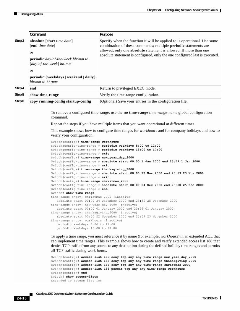
Chapter 24 Configuring Network Security with ACLsConfiguring ACLs
To remove a configured time-range, use the no time-range time-range-name global configuration command.
Repeat the steps if you have multiple items that you want operational at different times.
This example shows how to configure time ranges for workhours and for company holidays and how to verify your configuration.
Switch(config)# time-range workhoursSwitch(config-time-range)# periodic weekdays 8:00 to 12:00Switch(config-time-range)# periodic weekdays 13:00 to 17:00Switch(config-time-range)# exitSwitch(config)# time-range new_year_day_2000Switch(config-time-range)# absolute start 00:00 1 Jan 2000 end 23:59 1 Jan 2000Switch(config-time-range)# exitSwitch(config)# time-range thanksgiving_2000Switch(config-time-range)# absolute start 00:00 22 Nov 2000 end 23:59 23 Nov 2000Switch(config-time-range)# exitSwitch(config)# time-range christmas_2000Switch(config-time-range)# absolute start 00:00 24 Dec 2000 end 23:50 25 Dec 2000Switch(config-time-range)# endSwitch# show time-rangetime-range entry: christmas_2000 (inactive) absolute start 00:00 24 December 2000 end 23:50 25 December 2000time-range entry: new_year_day_2000 (inactive) absolute start 00:00 01 January 2000 end 23:59 01 January 2000time-range entry: thanksgiving_2000 (inactive) absolute start 00:00 22 November 2000 end 23:59 23 November 2000time-range entry: workhours (inactive) periodic weekdays 8:00 to 12:00 periodic weekdays 13:00 to 17:00
To apply a time range, you must reference it by name (for example, workhours) in an extended ACL that can implement time ranges. This example shows how to create and verify extended access list 188 that denies TCP traffic from any source to any destination during the defined holiday time ranges and permits all TCP traffic during work hours.
Switch(config)# access-list 188 deny tcp any any time-range new_year_day_2000Switch(config)# access-list 188 deny tcp any any time-range thanskgiving_2000Switch(config)# access-list 188 deny tcp any any time-range christmas_2000Switch(config)# access-list 188 permit tcp any any time-range workhoursSwitch(config)# endSwitch# show access-listsExtended IP access list 188
Step 3 absolute [start time date] [end time date]
or
periodic day-of-the-week hh:mm to [day-of-the-week] hh:mm
or
periodic {weekdays | weekend | daily} hh:mm to hh:mm
Specify when the function it will be applied to is operational. Use some combination of these commands; multiple periodic statements are allowed; only one absolute statement is allowed. If more than one absolute statement is configured, only the one configured last is executed.
Step 4 end Return to privileged EXEC mode.
Step 5 show time-range Verify the time-range configuration.
Step 6 copy running-config startup-config (Optional) Save your entries in the configuration file.
Command Purpose
24-16Catalyst 2950 Desktop Switch Software Configuration Guide
78-11380-05

Chapter 24 Configuring Network Security with ACLsConfiguring ACLs
deny tcp any any time-range new_year_day_2000 (inactive) deny tcp any any time-range thanskgiving_2000 (active) deny tcp any any time-range christmas_2000 (inactive) permit tcp any any time-range workhours (inactive)
This example uses named ACLs to permit and deny the same traffic.
Switch(config)# ip access-list extended deny_accessSwitch(config-ext-nacl)# deny tcp any any time-range new_year_day_2000Switch(config-ext-nacl)# deny tcp any any time-range thanksgiving_2000Switch(config-ext-nacl)# deny tcp any any time-range christmas_2000Switch(config-ext-nacl)# exitSwitch(config)# ip access-list extended may_accessSwitch(config-ext-nacl)# permit tcp any any time-range workhoursSwitch(config-ext-nacl)# endSwitch# show ip access-listsExtended IP access list deny_access deny tcp any any time-range new_year_day_2000 (inactive) deny tcp any any time-range thanksgiving_2000 (inactive) deny tcp any any time-range christmas_2000 (inactive)Extended IP access list may_access permit tcp any any time-range workhours (inactive)
Including Comments About Entries in ACLs
You can use the remark command to include comments (remarks) about entries in any IP standard or extended ACL. The remarks make the ACL easier for you to understand and scan. Each remark line is limited to 100 characters.
The remark can go before or after a permit or deny statement. You should be consistent about where you put the remark so that it is clear which remark describes which permit or deny statement. For example, it would be confusing to have some remarks before the associated permit or deny statements and some remarks after the associated statements.
For IP numbered standard or extended ACLs, use the access-list access-list number remark remark global configuration command to include a comment about an access list. To remove the remark, use the no form of this command.
In this example, the workstation belonging to Jones is allowed access, and the workstation belonging to Smith is not allowed access:
Switch(config)# access-list 1 remark Permit only Jones workstation throughSwitch(config)# access-list 1 permit 171.69.2.88Switch(config)# access-list 1 remark Do not allow Smith workstation throughSwitch(config)# access-list 1 deny 171.69.3.13
For an entry in a named IP ACL, use the remark access-list global configuration command. To remove the remark, use the no form of this command.
24-17Catalyst 2950 Desktop Switch Software Configuration Guide
78-11380-05

Chapter 24 Configuring Network Security with ACLsConfiguring ACLs
In this example, the Jones subnet is not allowed to use outbound Telnet:
Switch(config)# ip access-list extended telnettingSwitch(config-ext-nacl)# remark Do not allow Jones subnet to telnet outSwitch(config-ext-nacl)# deny tcp host 171.69.2.88 any eq telnet
Creating Named MAC Extended ACLsYou can filter Layer 2 traffic on a physical Layer 2 interface by using MAC addresses and named MAC extended ACLs. The procedure is similar to that of configuring other extended named access lists.
Note Named MAC extended ACLs are used as a part of the mac access-group privileged EXEC command.
For more information about the supported non-IP protocols in the mac access-list extended command, refer to the command reference for this release.
Note Matching on any SNAP-encapsulated packet with a nonzero Organizational Unique Identifier (OUI) is not supported.
Beginning in privileged EXEC mode, follow these steps to create a named MAC extended ACL:
Use the no mac access-list extended name global configuration command to delete the entire ACL. You can also delete individual ACEs from named MAC extended ACLs.
Command Purpose
Step 1 configure terminal Enter global configuration mode.
Step 2 mac access-list extended name Define an extended MAC access list by using a name.
Step 3 {deny | permit} {any | host source MAC address} {any | host destination MAC address} [aarp | amber | appletalk | dec-spanning | decnet-iv | diagnostic | dsm | etype-6000 | etype-8042 | lat | lavc-sca | mop-console | mop-dump | msdos | mumps | netbios | vines-echo |vines-ip | xns-idp]
In extended MAC access-list configuration mode, specify to permit or deny any source MAC address or a specific host source MAC address and any destination MAC address.
(Optional) You can also enter these options:
aarp | amber | appletalk | dec-spanning | decnet-iv | diagnostic | dsm | etype-6000 | etype-8042 | lat | lavc-sca | mop-console | mop-dump | msdos | mumps | netbios | vines-echo |vines-ip | xns-idp—(a non-IP protocol).
Step 4 end Return to privileged EXEC mode.
Step 5 show access-lists [number | name] Show the access list configuration.
Step 6 copy running-config startup-config (Optional) Save your entries in the configuration file.
24-18Catalyst 2950 Desktop Switch Software Configuration Guide
78-11380-05

Chapter 24 Configuring Network Security with ACLsConfiguring ACLs
This example shows how to create and display an access list named mac1, denying only EtherType DECnet Phase IV traffic, but permitting all other types of traffic.
Switch(config)# mac access-list extended mac1Switch(config-ext-macl)# deny any any decnet-ivSwitch(config-ext-macl)# permit any anySwitch(config-ext-macl)# endSwitch # show access-listExtended MAC access list mac1 deny any any decnet-iv permit any any
Creating MAC Access GroupsBeginning in privileged EXEC mode, follow these steps to create MAC access groups and to apply a MAC access list to an interface:
This example shows how to apply ACL 2 on Gigabit Ethernet interface 0/1 to filter packets entering the interface:
Switch(config)# interface gigabitethernet0/1Router(config-if)# mac access-group 2 in
Note The mac access-group interface configuration command is only valid when applied to a Layer 2 interface.
For inbound ACLs, after receiving a packet, the switch checks the packet against the ACL. If the ACL permits the packet, the switch continues to process the packet. If the ACL rejects the packet, the switch discards the packet. The MAC ACL applies to both IP and non-IP packets.
When you apply an undefined ACL to an interface, the switch acts as if the ACL has not been applied to the interface and permits all packets. Remember this behavior if you use undefined ACLs as a means of network security.
Command Purpose
Step 1 configure terminal Enter global configuration mode.
Step 2 interface interface-id Identify a specific interface for configuration, and enter interface configuration mode.
The interface must be a Layer 2 interface.
Step 3 mac access-group {name} {in} Control access to the specified interface by using the MAC access list name.
Step 4 end Return to privileged EXEC mode.
Step 5 show mac-access group Display the MAC ACLs applied on the switch.
Step 6 copy running-config startup-config (Optional) Save your entries in the configuration file.
24-19Catalyst 2950 Desktop Switch Software Configuration Guide
78-11380-05

Chapter 24 Configuring Network Security with ACLsApplying ACLs to Terminal Lines or Physical Interfaces
Applying ACLs to Terminal Lines or Physical Interfaces
Note Before applying an ACL to a physical interface, see the “Guidelines for Applying ACLs to Physical Interfaces” section on page 24-6.
You can apply ACLs to any management interface. For information on creating ACLs on management interfaces, refer to the “Configuring IP Services” section of the Cisco IOS IP and IP Routing Configuration Guide and the Command Reference for IOS Release 12.1.
Note The limitations that apply to ACLs on physical interfaces do not apply to ACLs on management interfaces.
After you create an ACL, you can apply it to one or more management interfaces or terminal lines. ACLs can be applied on inbound interfaces. This section describes how to accomplish this task for both terminal lines and network interfaces. Note these guidelines:
• When controlling access to a line, you must use numbered IP ACLs or MAC extended ACLs.
• When controlling access to an interface, you can use named or numbered ACLs.
• Set identical restrictions on all the virtual terminal lines because a user can attempt to connect to any of them.
• If you apply ACLs to a management interface, the ACL only filters packets that are intended for the CPU, such as SNMP, Telnet, or web traffic.
• If you apply ACLs to a management VLAN, see the “Management VLAN” section on page 6-19.
Applying ACLs to a Terminal LineBeginning in privileged EXEC mode, follow these steps to restrict incoming connections between a virtual terminal line and the addresses in an ACL:
Command Purpose
Step 1 configure terminal Enter global configuration mode.
Step 2 line [console | vty] line-number Identify a specific line for configuration, and enter in-line configuration mode.
Enter console for the console terminal line. The console port is DCE.
Enter vty for a virtual terminal for remote console access.
The line-number is the first line number in a contiguous group that you want to configure when the line type is specified. The range is from 0 to 16.
Step 3 access-class access-list-number {in} Restrict incoming and outgoing connections between a particular virtual terminal line (into a device) and the addresses in an access list.
Step 4 end Return to privileged EXEC mode.
Step 5 show running-config Display the access list configuration.
Step 6 copy running-config startup-config (Optional) Save your entries in the configuration file.
24-20Catalyst 2950 Desktop Switch Software Configuration Guide
78-11380-05

Chapter 24 Configuring Network Security with ACLsDisplaying ACL Information
Applying ACLs to a Physical InterfaceBeginning in privileged EXEC mode, follow these steps to control access to a Layer 2 interface:
This example shows how to apply access list 2 on Gigabit Ethernet interface 0/2 to filter packets entering the interface:
Switch(config)# interface gigabitethernet0/2Router(config-if)# ip access-group 2 in
Note The ip access-group interface configuration command is only valid when applied to a management interface or a Layer 2 physical interface. ACLs cannot be applied to interface port-channels.
For inbound ACLs, after receiving a packet, the switch checks the packet against the ACL. If the ACL permits the packet, the switch continues to process the packet. If the ACL rejects the packet, the switch discards the packet.
When you apply an undefined ACL to an interface, the switch acts as if the ACL has not been applied to the interface and permits all packets. Remember this behavior if you use undefined ACLs for network security.
Displaying ACL InformationYou can display the ACLs that are configured on the switch, and you can display the ACLs that have been applied to physical and management interfaces. This section consists of these topics:
• Displaying ACLs, page 24-22
• Displaying Access Groups, page 24-23
Command Purpose
Step 1 configure terminal Enter global configuration mode.
Step 2 interface interface-id Identify a specific interface for configuration and enter interface configuration mode.
The interface must be a Layer 2 or management interface or a management interface VLAN ID.
Step 3 ip access-group {access-list-number | name} {in}
Control access to the specified interface.
Step 4 end Return to privileged EXEC mode.
Step 5 show running-config Display the access list configuration.
Step 6 copy running-config startup-config (Optional) Save your entries in the configuration file.
24-21Catalyst 2950 Desktop Switch Software Configuration Guide
78-11380-05

Chapter 24 Configuring Network Security with ACLsDisplaying ACL Information
Displaying ACLsYou can display existing ACLs by using show commands.
Beginning in privileged EXEC mode, follow these steps to display access lists:
This example shows all standard and extended ACLs:
Switch# show access-listsStandard IP access list 1 permit 172.20.10.10Standard IP ACL 10 permit 12.12.12.12Standard IP access list 12 deny 1.3.3.2Standard IP access list 32 permit 172.20.20.20Standard IP access list 34 permit 10.24.35.56 permit 23.45.56.34Extended IP access list 120Extended MAC access list mac1
This example shows only IP standard and extended ACLs.
Switch# show ip access-listsStandard IP access list 1 permit 172.20.10.10Standard IP access list 10 permit 12.12.12.12Standard IP access list 12 deny 1.3.3.2Standard IP access list 32 permit 172.20.20.20Standard IP access list 34 permit 10.24.35.56 permit 23.45.56.34Extended IP access list 120
Command Purpose
Step 1 show access-lists [number | name] Show information about all IP and MAC address access lists or about a specific access list (numbered or named).
Step 2 show ip access-list [number | name] Show information about all IP address access lists or about a specific IP ACL (numbered or named).
24-22Catalyst 2950 Desktop Switch Software Configuration Guide
78-11380-05

Chapter 24 Configuring Network Security with ACLsExamples for Compiling ACLs
Displaying Access Groups
Note This feature is available only if your switch is running the EI.
You use the ip access-group interface configuration command to apply ACLs to a Layer 3 interface. When IP is enabled on an interface, you can use the show ip interface interface-id privileged EXEC command to view the input and output access lists on the interface, as well as other interface characteristics. If IP is not enabled on the interface, the access lists are not shown.
This example shows how to view all access groups configured for VLAN 1 and for Gigabit Ethernet interface 0/2:
Switch# show ip interface vlan 1GigabitEthernet0/2 is up, line protocol is down Internet address is 10.20.30.1/16 Broadcast address is 255.255.255.255 Address determined by setup command MTU is 1500 bytes Helper address is not set Directed broadcast forwarding is disabled Outgoing access list is permit Any Inbound access list is 13
<information truncated>
Switch# show ip interface fastethernet0/9FastEthernet0/9 is down, line protocol is down Inbound access list is ip1
The only way to ensure that you can view all configured access groups under all circumstances is to use the show running-config privileged EXEC command. To display the ACL configuration of a single interface, use the show running-config interface interface-id command.
This example shows how to display the ACL configuration of Gigabit Ethernet interface 0/1:
Switch# show running-config interface gigabitethernet0/1Building configuration...
Current configuration :112 bytes!interface GigabitEthernet0/1 ip access-group 11 in snmp trap link-status no cdp enableend!
Examples for Compiling ACLsFor detailed information about compiling ACLs, refer to the Security Configuration Guide and the “IP Services” chapter of the Cisco IOS IP and IP Routing Configuration Guide for IOS Release 12.1.
Figure 24-2 shows a small networked office with a stack of switches that are connected to a Cisco router. A host is connected to the network through the Internet using a WAN link.
24-23Catalyst 2950 Desktop Switch Software Configuration Guide
78-11380-05

Chapter 24 Configuring Network Security with ACLsExamples for Compiling ACLs
Use switch ACLs to do these:
• Create a standard ACL, and filter traffic from a specific Internet host with an address 172.20.128.64.
• Create an extended ACL, and filter traffic to deny HTTP access to all Internet hosts but allow all other types of access.
Figure 24-2 Using Switch ACLs to Control Traffic
This example uses a standard ACL to allow access to a specific Internet host with the address 172.20.128.64.
Switch(config)# access-list 6 permit 172.20.128.64 0.0.0.0Switch(config)# endSwitch(config)# interface gigabitethernet0/1Switch(config-if)# ip access-group 6 in
This example uses an extended ACL to deny traffic from port 80 (HTTP). It permits all other types of traffic.
Switch(config)# access-list 106 deny tcp any any eq 80Switch(config)# access-list 106 permit ip any anySwitch(config)# interface gigabitethernet0/2Switch(config-if)# ip access-group 106 in
Cisco router
Catalyst 2950
Catalyst 2950
Catalyst 2950
Workstation
Endworkstations 65
289
Internet
24-24Catalyst 2950 Desktop Switch Software Configuration Guide
78-11380-05

Chapter 24 Configuring Network Security with ACLsExamples for Compiling ACLs
Numbered ACL ExamplesThis example shows that the switch accepts addresses on network 36.0.0.0 subnets and denies all packets coming from 56.0.0.0 subnets. The ACL is then applied to packets entering Gigabit Ethernet interface 0/1.
Switch(config)# access-list 2 permit 36.0.0.0 0.255.255.255Switch(config)# access-list 2 deny 56.0.0.0 0.255.255.255Switch(config)# interface gigabitethernet0/1Switch(config-if)# ip access-group 2 in
Extended ACL ExamplesIn this example of using an extended ACL, you have a network connected to the Internet, and you want any host on the network to be able to form TCP Telnet and SMTP connections to any host on the Internet.
Switch(config)# access-list 102 permit tcp any 128.88.0.0 0.0.255.255 eq 23Switch(config)# access-list 102 permit tcp any 128.88.0.0 0.0.255.255 eq 25Switch(config)# interface gigabitethernet0/1Switch(config-if)# ip access-group 102 in
SMTP uses TCP port 25 on one end of the connection and a random port number on the other end. The same port numbers are used throughout the life of the connection. Mail packets coming in from the Internet have a destination port of 25. Because the secure system behind the switch always accepts mail connections on port 25, the incoming services are controlled.
Named ACL ExampleThe Marketing_group ACL allows any TCP Telnet traffic to the destination address and wildcard 171.69.0.0 0.0.255.255 and denies any other TCP traffic. It permits any other IP traffic.
Switch(config)# ip access-list extended marketing_groupSwitch(config-ext-nacl)# permit tcp any 171.69.0.0 0.0.255.255 eq telnetSwitch(config-ext-nacl)# deny tcp any anySwitch(config-ext-nacl)# permit ip any any
The ACLs are applied to permit Gigabit Ethernet port 0/1, which is configured as a Layer 2 port, with the Marketing_group ACL applied to incoming traffic.
Switch(config)# interface gigabitethernet0/1Switch(config-if)# ip access-group marketing_group in...
Commented IP ACL Entry ExamplesIn this example of a numbered ACL, the workstation belonging to Jones is allowed access, and the workstation belonging to Smith is not allowed access:
Switch(config)# access-list 1 remark Permit only Jones workstation throughSwitch(config)# access-list 1 permit 171.69.2.88Switch(config)# access-list 1 remark Do not allow Smith workstation throughSwitch(config)# access-list 1 deny 171.69.3.13
24-25Catalyst 2950 Desktop Switch Software Configuration Guide
78-11380-05

Chapter 24 Configuring Network Security with ACLsExamples for Compiling ACLs
In this example of a numbered ACL, the Winter and Smith workstations are not allowed to browse the web:
Switch(config)# access-list 100 remark Do not allow Winter to browse the webSwitch(config)# access-list 100 deny host 171.69.3.85 any eq wwwSwitch(config)# access-list 100 remark Do not allow Smith to browse the webSwitch(config)# access-list 100 deny host 171.69.3.13 any eq www
In this example of a named ACL, the Jones subnet is not allowed access:
Switch(config)# ip access-list standard preventionSwitch(config-std-nacl)# remark Do not allow Jones subnet throughSwitch(config-std-nacl)# deny 171.69.0.0 0.0.255.255
In this example of a named ACL, the Jones subnet is not allowed to use outbound Telnet:
Switch(config)# ip access-list extended telnettingSwitch(config-ext-nacl)# remark Do not allow Jones subnet to telnet outSwitch(config-ext-nacl)# deny tcp 171.69.0.0 0.0.255.255 any eq telnet
24-26Catalyst 2950 Desktop Switch Software Configuration Guide
78-11380-05

Catalyst 2950 Deskto78-11380-05
C H A P T E R 25
Configuring QoSThis chapter describes how to configure quality of service (QoS) by using QoS commands. With QoS, you can provide preferential treatment to certain types of traffic at the expense of others. Without QoS, the switch offers best-effort service to each packet, regardless of the packet contents or size. It sends the packets without any assurance of reliability, delay bounds, or throughput.
To use the features described in this chapter, you must have the enhanced software image (EI) installed on your switch.
If you have the standard software image (SI) installed on your switch, you cannot configure some of the features. Table 25-1 lists the sections that describe the features that you can configure.
Note For complete syntax and usage information for the commands used in this chapter, refer to the command reference for this release.
QoS can be configured either by using the Cluster Management Suite (CMS) or through the command-line interface (CLI). Refer to the CMS online help for configuration procedures through CMS. For information about accessing and using CMS, see Chapter 3, “Getting Started with CMS.”
You can also use these wizards to configure QoS only if your switch is running the EI:
• Priority data wizard—Lets you assign priority levels to data applications based on their TCP or UDP ports. It provides a standard list of applications, and you select the ones that you want to prioritize, the priority levels, and the interfaces where the prioritization occurs. Refer to the priority data wizard online help for procedures about using this wizard.
Table 25-1 Sections Describing Standard Software Features
Topic Section
Queueing and scheduling at the egress ports
“Queueing and Scheduling” section on page 25-7
Configuring QoS “Configuring QoS” section on page 25-9
“Default QoS Configuration” section on page 25-9
“Configuring Classification Using Port Trust States” section on page 25-10
“Configuring CoS and WRR” section on page 25-27
25-1p Switch Software Configuration Guide

Chapter 25 Configuring QoSUnderstanding QoS
• Video wizard—Gives traffic that originates from specified video servers a higher priority than the priority of data traffic. The wizard assumes that the video servers are connected to a single device in the cluster. Refer to the video wizard online help for procedures about using this wizard.
This chapter consists of these sections:
• Understanding QoS, page 25-2
• Configuring QoS, page 25-9
• Displaying QoS Information, page 25-28
• QoS Configuration Examples, page 25-29
Understanding QoSThis section describes how QoS is implemented on the switch. If you have the SI installed on your switch, some concepts and features in this section might not apply. For a list of available features, see Table 25-1 on page 25-1.
Typically, networks operate on a best-effort delivery basis, which means that all traffic has equal priority and an equal chance of being delivered in a timely manner. When congestion occurs, all traffic has an equal chance of being dropped.
When you configure the QoS feature, you can select specific network traffic, prioritize it according to its relative importance, and use congestion-management and congestion-avoidance techniques to provide preferential treatment. Implementing QoS in your network makes network performance more predictable and bandwidth utilization more effective.
The QoS implementation is based on the DiffServ architecture, an emerging standard from the Internet Engineering Task Force (IETF). This architecture specifies that each packet is classified upon entry into the network. The classification is carried in the IP packet header, using 6 bits from the deprecated IP type-of-service (ToS) field to carry the classification (class) information.
Classification can also be carried in the Layer 2 frame. These special bits in the Layer 2 frame or a Layer 3 packet are described here and shown in Figure 25-1:
• Prioritization values in Layer 2 frames
Layer 2 802.1Q frame headers have a 2-byte Tag Control Information field that carries the class of service (CoS) value in the three most-significant bits, which are called the User Priority bits. On interfaces configured as Layer 2 802.1Q trunks, all traffic is in 802.1Q frames except for traffic in the native VLAN.
Other frame types cannot carry Layer 2 CoS values.
Layer 2 CoS values range from 0 for low priority to 7 for high priority.
• Prioritization bits in Layer 3 packets
Layer 3 IP packets can carry a Differentiated Services Code Point (DSCP) value. The supported DSCP values are 0, 8, 10, 16, 18, 24, 26, 32, 34, 40, 46, 48, and 56.
25-2Catalyst 2950 Desktop Switch Software Configuration Guide
78-11380-05

Chapter 25 Configuring QoSUnderstanding QoS
Figure 25-1 QoS Classification Layers in Frames and Packets
All switches and routers that access the Internet rely on the class information to provide the same forwarding treatment to packets with the same class information and different treatment to packets with different class information. The class information in the packet can be assigned by end hosts or by switches or routers along the way, based on a configured policy, detailed examination of the packet, or both. Detailed examination of the packet is expected to happen closer to the edge of the network so that the core switches and routers are not overloaded.
Switches and routers along the path can use the class information to limit the amount of resources allocated per traffic class. The behavior of an individual device when handling traffic in the DiffServ architecture is called per-hop behavior. If all devices along a path provide a consistent per-hop behavior, you can construct an end-to-end QoS solution.
Implementing QoS in your network can be a simple or complex task and depends on the QoS features offered by your internetworking devices, the traffic types and patterns in your network, and the granularity of control that you need over incoming and outgoing traffic.
Basic QoS ModelFigure 25-2 shows the basic QoS model. Actions at the ingress interface include classifying traffic, policing, and marking:
Note If you have the SI installed on your switch, only the queueing and scheduling features are available.
• Classifying distinguishes one kind of traffic from another. For more information, see the “Classification” section on page 25-4.
• Policing determines whether a packet is in or out of profile according to the configured policer, and the policer limits the bandwidth consumed by a flow of traffic. The result of this determination is passed to the marker. For more information, see the “Policing and Marking” section on page 25-6.
6098
0
Encapsulated Packet
Layer 2header
IP header Data
Layer 2 802.1Q/P Frame
Preamble Start framedelimiter
DA
Len
SA Tag PT Data FCS
Layer 3 IPv4 Packet
Versionlength
ToS(1 byte)
ID Offset TTL Proto FCS IP-SA IP-DA Data
3 bits used for CoS (user priority)
DSCP
25-3Catalyst 2950 Desktop Switch Software Configuration Guide
78-11380-05

Chapter 25 Configuring QoSUnderstanding QoS
• Marking evaluates the policer and configuration information for the action to be taken when a packet is out of profile and decides what to do with the packet (pass through a packet without modification, mark down the DSCP value in the packet, or drop the packet). For more information, see the “Policing and Marking” section on page 25-6.
Actions at the egress interface include queueing and scheduling:
• Queueing evaluates the CoS value and determines which of the four egress queues in which to place the packet.
• Scheduling services the four egress queues based on their configured weighted round robin (WRR) weights.
Figure 25-2 Basic QoS Model
Classification
Note This feature is available only if your switch is running the EI.
Classification is the process of distinguishing one kind of traffic from another by examining the fields in the packet.
Classification occurs only on a physical interface basis. No support exists for classifying packets at the VLAN level.
You specify which fields in the frame or packet that you want to use to classify incoming traffic.
For non-IP traffic, you have these classification options:
• Use the port default. If the frame does not contain a CoS value, the switch assigns the default port CoS value to the incoming frame.
• Trust the CoS value in the incoming frame (configure the port to trust CoS). Layer 2 802.1Q frame headers carry the CoS value in the three most-significant bits of the Tag Control Information field. CoS values range from 0 for low priority to 7 for high priority.
6097
9
Classification Policing
Actions at ingress Actions at egress
Mark
In profile orout of profile
Classify the packet based on the ACL.
Determine if the packet is in profile or out of profile based on the policer associated with the filter.
Based on whether the packet is in or out of profile and the configured parameters, determine whether to pass through, mark down, or drop the packet. The DSCP and CoS are marked or changed accordingly.
Queueing andscheduling
Based on the CoS, determine into which of the egress queues to place the packet. Then service the queues according to the configured weights.
25-4Catalyst 2950 Desktop Switch Software Configuration Guide
78-11380-05

Chapter 25 Configuring QoSUnderstanding QoS
The trust DSCP configuration is meaningless for non-IP traffic. If you configure a port with this option and non-IP traffic is received, the switch assigns the default port CoS value and classifies traffic based on the CoS value.
For IP traffic, you have these classification options:
• Trust the IP DSCP in the incoming packet (configure the port to trust DSCP). The switch assigns the same DSCP to the packet for internal use. The IETF defines the 6 most-significant bits of the 1-byte ToS field as the DSCP. The priority represented by a particular DSCP value is configurable. The supported DSCP values are 0, 8, 10, 16, 18, 24, 26, 32, 34, 40, 46, 48, and 56.
• Trust the CoS value (if present) in the incoming packet. The switch generates the DSCP by using the CoS-to-DSCP map.
Note An interface can be configured to trust either CoS or DSCP, but not both at the same time.
Classification Based on QoS ACLs
You can use IP standard, IP extended, and Layer 2 MAC access control lists (ACLs) to define a group of packets with the same characteristics (class). In the QoS context, the permit and deny actions in the access control entries (ACEs) have different meanings than with security ACLs:
• If a match with a permit action is encountered (first-match principle), the specified QoS-related action is taken.
• If no match with a permit action is encountered and all the ACEs have been examined, no QoS processing occurs on the packet.
• If multiple ACLs are configured on an interface, the packet matches the first ACL with a permit action, and QoS processing begins.
• Configuration of a deny action is not supported in QoS ACLs on the switch.
• System-defined masks are allowed in class maps with these restrictions:
– A combination of system-defined and user-defined masks cannot be used in the multiple class maps that are a part of a policy map.
– System-defined masks that are a part of a policy map must all use the same type of system mask. For example, a policy map cannot have a class map that uses the permit tcp any any ACE and another that uses the permit ip any any ACE.
– A policy map can contain multiple class maps that all use the same user-defined mask or the same system-defined mask.
Note For more information about system-defined masks, see the “Understanding Access Control Parameters” section on page 24-4.
For more information about ACL restrictions, see the “Configuring ACLs” section on page 24-6.
After a traffic class has been defined with the ACL, you can attach a policy to it. A policy might contain multiple classes with actions specified for each one of them. A policy might include commands to classify the class as a particular aggregate (for example, assign a DSCP) or rate-limit the class. This policy is then attached to a particular port on which it becomes effective.
You implement IP ACLs to classify IP traffic by using the access-list global configuration command; you implement Layer 2 MAC ACLs to classify Layer 2 traffic by using the mac access-list extended global configuration command.
25-5Catalyst 2950 Desktop Switch Software Configuration Guide
78-11380-05

Chapter 25 Configuring QoSUnderstanding QoS
Classification Based on Class Maps and Policy Maps
A class map is a mechanism that you use to isolate and name a specific traffic flow (or class) from all other traffic. The class map defines the criteria used to match against a specific traffic flow to further classify it; the criteria can include matching the access group defined by the ACL. If you have more than one type of traffic that you want to classify, you can create another class map and use a different name. After a packet is matched against the class-map criteria, you further classify it through the use of a policy map.
A policy map specifies which traffic class to act on. Actions can include setting a specific DSCP value in the traffic class or specifying the traffic bandwidth limitations and the action to take when the traffic is out of profile. Before a policy map can be effective, you must attach it to an interface.
You create a class map by using the class-map global configuration command or the class policy-map configuration command. You should use the class-map global configuration command when the map is shared among many ports. When you enter the class-map global configuration command, the switch enters the class-map configuration mode. In this mode, you define the match criterion for the traffic by using the match class-map configuration command.
You create and name a policy map by using the policy-map global configuration command. When you enter this command, the switch enters the policy-map configuration mode. In this mode, you specify the actions to take on a specific traffic class by using the class policy-map configuration or set policy-map class configuration command. To make the policy map effective, you attach it to an interface by using the service-policy interface configuration command.
The policy map can also contain commands that define the policer, the bandwidth limitations of the traffic, and the action to take if the limits are exceeded. For more information, see the “Policing and Marking” section on page 25-6.
A policy map also has these characteristics:
• A policy map can contain multiple class statements.
• A separate policy-map class can exist for each type of traffic received through an interface.
• A policy-map configuration state supersedes any actions due to an interface trust state.
For configuration information, see the “Configuring a QoS Policy” section on page 25-16.
Policing and Marking
Note This feature is available only if your switch is running the EI.
Policing involves creating a policer that specifies the bandwidth limits for the traffic. Packets that exceed the limits are out of profile or nonconforming. Each policer specifies the action to take for packets that are in or out of profile. These actions, carried out by the marker, include dropping the packet or marking down the packet with a new user-defined value.
You can create an individual policer. QoS applies the bandwidth limits specified in the policer separately to each matched traffic class. You configure this type of policer within a policy map by using the policy-map configuration command.
When configuring policing and policers, keep these items in mind:
• By default, no policers are configured.
• Policers can only be configured on a physical port. There is no support for policing at a VLAN level.
25-6Catalyst 2950 Desktop Switch Software Configuration Guide
78-11380-05

Chapter 25 Configuring QoSUnderstanding QoS
• Only one policer can be applied to a packet in the input direction.
• Only the average rate and committed burst parameters are configurable.
• Policing occurs on the ingress interfaces:
– 60 policers are supported on ingress Gigabit-capable Ethernet ports.
– 6 policers are supported on ingress 10/100 Ethernet ports.
– Granularity for the average burst rate is 1 Mbps for 10/100 ports and 8 Mbps for Gigabit Ethernet ports.
• On an interface configured for QoS, all traffic received through the interface is classified, policed, and marked according to the policy map attached to the interface. On a trunk interface configured for QoS, traffic in all VLANs received through the interface is classified, policed, and marked according to the policy map attached to the interface.
Note You cannot configure policers on the egress interfaces.
Mapping Tables
Note This feature is available only if your switch is running the EI.
During classification, QoS uses a configurable CoS-to-DSCP map to derive an internal DSCP value from the received CoS value. This DSCP value represents the priority of the traffic.
Before the traffic reaches the scheduling stage, QoS uses the configurable DSCP-to-CoS map to derive a CoS value from the internal DSCP value. The CoS value is used to select one of the four egress queues.
The CoS-to-DSCP and DSCP-to-CoS maps have default values that might or might not be appropriate for your network.
For configuration information, see the “Configuring CoS Maps” section on page 25-24.
Queueing and Scheduling
Note Both the EI and SI support this feature.
The switch provides QoS-based 802.1P CoS values. QoS uses classification and scheduling to send network traffic from the switch in a predictable manner. QoS classifies frames by assigning priority-indexed CoS values to them and gives preference to higher-priority traffic such as telephone calls.
How Class of Service Works
Before you set up 802.1P CoS on a Catalyst 2950 switch that operates with the Catalyst 6000 family of switches, refer to the Catalyst 6000 documentation. There are differences in the 802.1P implementation that you should understand to ensure compatibility.
25-7Catalyst 2950 Desktop Switch Software Configuration Guide
78-11380-05

Chapter 25 Configuring QoSUnderstanding QoS
Port Priority
Frames received from users in the administratively-defined VLANs are classified or tagged for transmission to other devices. Based on rules that you define, a unique identifier (the tag) is inserted in each frame header before it is forwarded. The tag is examined and understood by each device before any broadcasts or transmissions to other switches, routers, or end stations. When the frame reaches the last switch or router, the tag is removed before the frame is sent to the target end station. VLANs that are assigned on trunk or access ports without identification or a tag are called native or untagged frames.
For IEEE 802.1Q frames with tag information, the priority value from the header frame is used. For native frames, the default priority of the input port is used.
Port Scheduling
Each port on the switch has a single receive queue buffer (the ingress port) for incoming traffic. When an untagged frame arrives, it is assigned the value of the port as its port default priority. You assign this value by using the CLI or CMS. A tagged frame continues to use its assigned CoS value when it passes through the ingress port.
CoS configures each transmit port (the egress port) with a normal-priority transmit queue and a high-priority transmit queue, depending on the frame tag or the port information. Frames in the normal-priority queue are forwarded only after frames in the high-priority queue are forwarded.
The switch (802.1P user priority) has four priority queues. The frames are forwarded to appropriate queues based on the priority-to-queue mapping that you defined.
CoS and WRR
The switch supports four CoS queues for each egress port. For each queue, you can specify these types of scheduling:
• Strict priority scheduling
Strict priority scheduling is based on the priority of queues. Queues can have priorities from 0 to 7, 7 being the highest. Packets in the high-priority queue always transmit first, and packets in the low-priority queue do not transmit until all the high-priority queues become empty.
• Weighted round-robin (WRR) scheduling
WRR scheduling requires you to specify a number that indicates the importance (weight) of the queue relative to the other CoS queues. WRR scheduling prevents the low-priority queues from being completely neglected during periods of high-priority traffic. The WRR scheduler transmits some packets from each queue in turn. The number of packets it sends corresponds to the relative importance of the queue. For example, if one queue has a weight of 3 and another has a weight of 4, three packets are sent from the first queue for every four that are sent from the second queue. By using this scheduling, low-priority queues have the opportunity to send packets even though the high-priority queues are not empty.
25-8Catalyst 2950 Desktop Switch Software Configuration Guide
78-11380-05

Chapter 25 Configuring QoSConfiguring QoS
Configuring QoSBefore configuring QoS, you must have a thorough understanding of these items:
• The types of applications used and the traffic patterns on your network.
• Traffic characteristics and needs of your network. Is the traffic bursty? Do you need to reserve bandwidth for voice and video streams?
• Bandwidth requirements and speed of the network.
• Location of congestion points in the network.
This section describes how to configure QoS on your switch:
Note If your switch is running the SI, you can configure only the features described in the “Configuring Classification Using Port Trust States” and the “Configuring CoS and WRR” sections. You can also display the QoS information as described in the “Displaying QoS Information” section.
• Default QoS Configuration, page 25-9
• Configuration Guidelines, page 25-10
• Configuring Classification Using Port Trust States, page 25-10
• Configuring a QoS Policy, page 25-16
• Configuring CoS Maps, page 25-24
• Configuring CoS and WRR, page 25-27
Default QoS ConfigurationThis is the default QoS configuration:
Note You can configure policy maps, policers, the CoS-to-DSCP map, and the DSCP-to-CoS map only if your switch is running the EI.
• The default port CoS value is 0.
• The CoS value of 0 is assigned to all incoming packets.
• The default port trust state is untrusted.
• No policy maps are configured.
• No policers are configured.
• The default CoS-to-DSCP map is shown in Table 25-3.
• The default DSCP-to-CoS map is shown in Table 25-4.
• For default QoS and WRR values, see the “Configuring CoS and WRR” section on page 25-27.
Note In software releases earlier than Release 12.1(11)EA1, the switch uses the CoS value of incoming packets without modifying the DSCP value. You can configure this by enabling pass-through mode on the port. For more information, see the “Enabling Pass-Through Mode” section on page 25-15.
25-9Catalyst 2950 Desktop Switch Software Configuration Guide
78-11380-05

Chapter 25 Configuring QoSConfiguring QoS
Configuration Guidelines
Note These guidelines are applicable only if your switch is running the EI.
Before beginning the QoS configuration, you should be aware of this information:
• If you have EtherChannel ports configured on your switch, you must configure QoS classification, policing, mapping, and queueing on the individual physical ports that comprise the EtherChannel. You must decide whether the QoS configuration should match on all ports in the EtherChannel.
• It is not possible to match IP fragments against configured IP extended ACLs to enforce QoS. IP fragments are sent as best-effort traffic. IP fragments are denoted by fields in the IP header.
• All ingress QoS processing actions apply to control traffic (such as spanning-tree bridge protocol data units [BPDUs] and routing update packets) that the switch receives.
• Only an ACL that is created for physical interfaces can be attached to a class map.
• Only one ACL per class map and only one match command per class map are supported. The ACL can have multiple access control entries, which are commands that match fields against the contents of the packet.
• Policy maps with ACL classification in the egress direction are not supported and cannot be attached to an interface by using the service-policy input policy-map-name interface configuration command.
• In a policy map, the class named class-default is not supported. The switch does not filter traffic based on the policy map defined by the class class-default policy-map configuration command.
• For more information about guidelines for configuring ACLs, see the “Classification Based on QoS ACLs” section on page 25-5.
• For information about applying ACLs to physical interfaces, see the “Guidelines for Applying ACLs to Physical Interfaces” section on page 24-6.
Note Do not configure QoS when IEEE 802.3X flowcontrol is configured on the switch. Before configuring QoS on an interface, make sure to disable flowcontrol on the switch.
Configuring Classification Using Port Trust StatesThis section describes how to classify incoming traffic by using port trust states:
• Configuring the Trust State on Ports within the QoS Domain, page 25-11
• Configuring the CoS Value for an Interface, page 25-13
• Configuring Trusted Boundary, page 25-13
• Enabling Pass-Through Mode, page 25-15
25-10Catalyst 2950 Desktop Switch Software Configuration Guide
78-11380-05

Chapter 25 Configuring QoSConfiguring QoS
Note Both the EI and SI support this feature.
Configuring the Trust State on Ports within the QoS Domain
Packets entering a QoS domain are classified at the edge of the QoS domain. When the packets are classified at the edge, the switch port within the QoS domain can be configured to one of the trusted states because there is no need to classify the packets at every switch within the QoS domain. Figure 25-3 shows a sample network topology.
Figure 25-3 Port Trusted States within the QoS Domain
8116
3
Catalyst3550-12T switch
Trunk
Trusted interface
Classificationof trafficperformed here
Catalyst 2950wiring closet
IP
25-11Catalyst 2950 Desktop Switch Software Configuration Guide
78-11380-05

Chapter 25 Configuring QoSConfiguring QoS
Beginning in privileged EXEC mode, follow these steps to configure the port to trust the classification of the traffic that it receives:
To return a port to its untrusted state, use the no mls qos trust interface configuration command.
For information on how to change the default CoS value, see the “Configuring the CoS Value for an Interface” section on page 25-13. For information on how to configure the CoS-to-DSCP map, see the “Configuring the CoS-to-DSCP Map” section on page 25-25.
Command Purpose
Step 1 configure terminal Enter global configuration mode.
Step 2 interface interface-id Enter interface configuration mode, and specify the interface to be trusted.
Valid interfaces include physical interfaces.
Step 3 mls qos trust [cos | dscp] Configure the port trust state.
By default, the port is not trusted.
The keywords have these meanings:
cos—Classifies ingress packets with the packet CoS values. For tagged IP packets, the DSCP value of the packet is modified based on the CoS-to-DSCP map. The egress queue assigned to the packet is based on the packet CoS value.
dscp—Classifies ingress packets with packet DSCP values. For non-IP packets, the packet CoS value is set to 0 for tagged packets; the default port CoS is used for untagged packets. Internally, the switch modifies the CoS value by using the DSCP-to-CoS map. This keyword is available only if your switch is running the EI.
Note In software releases earlier than Release 12.1(11)EA1, the mls qos trust command is available only when the switch is running the EI.
Use the cos keyword if your network is composed of Ethernet LANs.
Use the dscp keyword if your network is not composed of only Ethernet LANs and if you are familiar with sophisticated QoS features and implementations.
For more information about this command, refer to the command reference for this release.
Step 4 end Return to privileged EXEC mode.
Step 5 show mls qos interface [interface-id] [policers]
Verify your entries.
Step 6 copy running-config startup-config (Optional) Save your entries in the configuration file.
25-12Catalyst 2950 Desktop Switch Software Configuration Guide
78-11380-05

Chapter 25 Configuring QoSConfiguring QoS
Configuring the CoS Value for an Interface
QoS assigns the CoS value specified with the mls qos cos interface configuration command to untagged frames received on trusted and untrusted ports.
Beginning in privileged EXEC mode, follow these steps to define the default CoS value of a port or to assign the default CoS to all incoming packets on the port:
To return to the default setting, use the no mls qos cos {default-cos | override} interface configuration command.
Configuring Trusted Boundary
In a typical network, you connect a Cisco IP phone to a switch port as shown in Figure 25-3 on page 25-11. Traffic sent from the telephone to the switch is typically marked with a tag that uses the 802.1Q header. The header contains the VLAN information and the CoS 3-bit field, which determines the priority of the packet. For most Cisco IP phone configurations, the traffic sent from the telephone to the switch is trusted to ensure that voice traffic is properly prioritized over other types of traffic in the network. By using the mls qos trust cos interface configuration command, you can configure the switch port to which the telephone is connected to trust the CoS labels of all traffic received on that port.
In some situations, you also might connect a PC or workstation to the IP phone. In these cases, you can use the switchport priority extend cos interface configuration command to configure the telephone through the switch CLI to override the priority of the traffic received from the PC. With this command, you can prevent a PC from taking advantage of a high-priority data queue.
Command Purpose
Step 1 configure terminal Enter global configuration mode.
Step 2 interface interface-id Enter interface configuration mode, and specify the interface to be trusted.
Valid interfaces include physical interfaces.
Step 3 mls qos cos {default-cos | override} Configure the default CoS value for the port.
• For default-cos, specify a default CoS value to be assigned to a port. If the port is CoS trusted and packets are untagged, the default CoS value becomes the CoS value for the packet. The CoS range is 0 to 7. The default is 0.
• Use the override keyword to override the previously configured trust state of the incoming packets and to apply the default port CoS value to all incoming packets. By default, CoS override is disabled.
Use the override keyword when all incoming packets on certain ports deserve higher priority than packets entering from other ports. Even if a port was previously set to trust DSCP, this command overrides the previously configured trust state, and all the incoming CoS values are assigned the default CoS value configured with this command. If an incoming packet is tagged, the CoS value of the packet is modified with the default CoS of the port at the egress port.
Step 4 end Return to privileged EXEC mode.
Step 5 show mls qos interface Verify your entries.
Step 6 copy running-config startup-config (Optional) Save your entries in the configuration file.
25-13Catalyst 2950 Desktop Switch Software Configuration Guide
78-11380-05

Chapter 25 Configuring QoSConfiguring QoS
However, if a user bypasses the telephone and connects the PC directly to the switch, the CoS labels generated by the PC are trusted by the switch (because of the trusted CoS setting) and can allow misuse of high-priority queues. The trusted boundary feature solves this problem by using the Cisco Discovery Protocol (CDP) to detect the presence of a Cisco IP phone (such as the Cisco IP Phone 7910, 7935, 7940, and 7960) on a switch port. If the telephone is not detected, the trusted boundary feature disables the trusted setting on the switch port and prevents misuse of a high-priority queue.
Beginning in privileged EXEC mode, follow these steps to configure trusted boundary on a switch port:
When you enter the no mls qos trust interface configuration command, trusted boundary is not disabled. If this command is entered and the port is connected to a Cisco IP phone, the port does not trust the classification of traffic that it receives. To disable trusted boundary, use the no mls qos trust device interface configuration command
If you enter the mls qos cos override interface configuration command, the port does not trust the classification of the traffic that it receives, even when it is connected to a Cisco IP phone.
Table 25-2 lists the port configuration when an IP phone is present or absent.
Command Purpose
Step 1 configure terminal Enter global configuration mode.
Step 2 cdp enable Enable CDP globally. By default, it is enabled.
Step 3 interface interface-id Enter interface configuration mode, and specify the interface to be trusted.
Valid interfaces include physical interfaces.
Step 4 cdp enable Enable CDP on the interface. By default, CDP is enabled.
Step 5 mls qos trust device cisco-phone Configure the Cisco IP phone as a trusted device on the interface.
Step 6 mls qos trust cos Configure the port trust state to trust the CoS value of the ingress packet.
By default, the port is not trusted.
Note In software releases earlier than Release 12.1(11)EA1, the mls qos trust cos command is available only when the switch is running the EI.
For more information on this command, refer to the command reference for this release.
Step 7 end Return to privileged EXEC mode.
Step 8 show mls qos interface [interface-id] [policers]
Verify your entries.
Step 9 copy running-config startup-config (Optional) Save your entries in the configuration file.
25-14Catalyst 2950 Desktop Switch Software Configuration Guide
78-11380-05

Chapter 25 Configuring QoSConfiguring QoS
Enabling Pass-Through Mode
In software releases earlier than Release 12.1(11)EA1, the switch is in pass-through mode. It uses the CoS value of incoming packets without modifying the DSCP value and sends the packets from one of the four egress queues. You cannot enable or disable pass-through mode if your switch is running a software release earlier than Release 12.1(11)EA1.
In Release 12.1(11)EA1 or later, the switch assigns a CoS value of 0 to all incoming packets without modifying the packets. The switch offers best-effort service to each packet regardless of the packet contents or size and sends it from a single egress queue.
Beginning in privileged EXEC mode, follow these steps to enable pass-through mode:
To disable pass-through mode, use the no mls qos trust pass-through dscp interface configuration command.
If you enter the mls qos cos override and the mls qos trust [cos | dscp] interface commands when pass-through mode is enabled, pass-through mode is disabled.
If you enter the mls qos trust cos pass-through dscp interface configuration command when the mls qos cos override and the mls qos trust [cos | dscp] interface commands are already configured, pass-through mode is disabled.
Table 25-2 Port Configurations When Trusted Boundary is Enabled
Port Configuration When a Cisco IP Phone is Present When a Cisco IP Phone is Absent
The port trusts the CoS value of the incoming packet.
The packet CoS value is trusted. The packet CoS value is assigned the default CoS value.
The port trusts the DSCP value of the incoming packet.
The packet DSCP value is trusted. For tagged non-IP packets, the packet CoS value is set to 0.
For untagged non-IP packets, the packet CoS value is assigned the default CoS value.
The port assigns the default CoS value to incoming packets.
The packet CoS value is assigned the default CoS value.
The packet CoS value is assigned the default CoS value.
Command Purpose
Step 1 configure terminal Enter global configuration mode.
Step 2 interface interface-id Enter interface configuration mode, and specify the interface on which pass-through mode is enabled.
Valid interfaces include physical interfaces.
Step 3 mls qos trust cos pass-through dscp Enable pass-through mode. The interface is configured to trust the CoS value of the incoming packets and to send them without modifying the DSCP value.
Step 4 end Return to privileged EXEC mode.
Step 5 show mls qos interface [interface-id] Verify your entries.
Step 6 copy running-config startup-config (Optional) Save your entries in the configuration file.
25-15Catalyst 2950 Desktop Switch Software Configuration Guide
78-11380-05

Chapter 25 Configuring QoSConfiguring QoS
Configuring a QoS Policy
Note This feature is available only if your switch is running the EI.
Configuring a QoS policy typically requires classifying traffic into classes, configuring policies applied to those traffic classes, and attaching policies to interfaces.
For background information, see the “Classification” section on page 25-4 and the “Policing and Marking” section on page 25-6.
This section contains this configuration information:
• Classifying Traffic by Using ACLs, page 25-16
• Classifying Traffic by Using Class Maps, page 25-20
• Classifying, Policing, and Marking Traffic by Using Policy Maps, page 25-21
Classifying Traffic by Using ACLs
You can classify IP traffic by using IP standard or IP extended ACLs; you can classify Layer 2 traffic by using Layer 2 MAC ACLs.
Beginning in privileged EXEC mode, follow these steps to create an IP standard ACL for IP traffic:
Command Purpose
Step 1 configure terminal Enter global configuration mode.
Step 2 access-list access-list-number {permit | remark} {source source-wildcard | host source | any}
Create an IP standard ACL, repeating the command as many times as necessary.
For access-list-number, enter the ACL number. The range is 1 to 99 and 1300 to 1999.
Enter permit to specify whether to permit access if conditions are matched.
Enter remark to specify an ACL entry comment up to 100 characters.
Note Deny statements are not supported for QoS ACLs. See the “Classification Based on QoS ACLs” section on page 25-5 for more details.
The source is the source address of the network or host from which the packet is being sent, specified in one of three ways:
• The 32-bit quantity in dotted decimal format.
• The keyword any as an abbreviation for source and source-wildcard of 0.0.0.0 255.255.255.255. You do not need to enter a source wildcard.
• The keyword host as an abbreviation for source and source-wildcard of source 0.0.0.0.
(Optional) The source-wildcard variable applies wildcard bits to the source (see first bullet item).
25-16Catalyst 2950 Desktop Switch Software Configuration Guide
78-11380-05

Chapter 25 Configuring QoSConfiguring QoS
For more information about creating IP standard ACLs, see the “Guidelines for Applying ACLs to Physical Interfaces” section on page 24-6.
To delete an ACL, use the no access-list access-list-number global configuration command.
This example shows how to allow access for only those hosts on the two specified networks. The wildcard bits apply to the host portions of the network addresses. Any host with a source address that does not match the ACL statements is rejected.
Switch(config)# access-list 1 permit 192.5.255.0 0.0.0.255Switch(config)# access-list 1 permit 36.0.0.0 0.0.0.255
Step 3 end Return to privileged EXEC mode.
Step 4 show access-lists Verify your entries.
Step 5 copy running-config startup-config (Optional) Save your entries in the configuration file.
Command Purpose
25-17Catalyst 2950 Desktop Switch Software Configuration Guide
78-11380-05

Chapter 25 Configuring QoSConfiguring QoS
Beginning in privileged EXEC mode, follow these steps to create an IP extended ACL for IP traffic:
Command Purpose
Step 1 configure terminal Enter global configuration mode.
Step 2 access-list access-list-number {permit | remark} protocol {source source-wildcard | host source | any} [operator port] {destination destination-wildcard | host destination | any} [operator port] [dscp dscp-value] [time-range time-range-name]
Create an IP extended ACL, repeating the command as many times as necessary.
For access-list-number, enter the ACL number. The range is 100 to 199 and 2000 to 2699.
Enter permit to permit access if conditions are matched.
Enter remark to specify an ACL entry comment up to 100 characters.
Note Deny statements are not supported for QoS ACLs. See the “Classification Based on QoS ACLs” section on page 25-5 for more details.
For protocol, enter the name or number of an IP protocol. Use the question mark (?) to see a list of available protocol keywords.
For source, enter the network or host from which the packet is being sent. For source-wildcard, enter the wildcard bits by placing ones in the bit positions that you want to ignore. You specify the source and source-wilcard by using dotted decimal notation, by using the any keyword as an abbreviation for source 0.0.0.0 source-wildcard 255.255.255.255, or by using the host keyword for source 0.0.0.0.
For destination, enter the network or host to which the packet is being sent. You have the same options for specifying the destination and destination-wildcard as those described for source and source-wildcard.
Define a destination or source port.
• The operator can be only eq (equal).
• If operator is after source source-wildcard, conditions match when the source port matches the defined port.
• If operator is after destination destination-wildcard, conditions match when the destination port matches the defined port.
• The port is a decimal number or name of a TCP or UDP port. The number can be from 0 to 65535.
• Use TCP port names only for TCP traffic.
• Use UDP port names only for UDP traffic.
Enter dscp to match packets with any of the 13 supported DSCP values (0, 8, 10, 16, 18, 24, 26, 32, 34, 40, 46, 48, and 56) or use the question mark (?) to see a list of available values.
The time-range keyword is optional. For information about this keyword, see the “Applying Time Ranges to ACLs” section on page 24-15.
Step 3 end Return to privileged EXEC mode.
25-18Catalyst 2950 Desktop Switch Software Configuration Guide
78-11380-05

Chapter 25 Configuring QoSConfiguring QoS
For more information about creating IP extended ACLs, see the “Guidelines for Applying ACLs to Physical Interfaces” section on page 24-6.
To delete an ACL, use the no access-list access-list-number global configuration command.
This example shows how to create an ACL that permits only TCP traffic from the destination IP address 128.88.1.2 with TCP port number 25:
Switch(config)# access-list 102 permit tcp 0.0.0.0 255.255.255.255 128.88.1.2 0.0.0.0 eq 25
Beginning in privileged EXEC mode, follow these steps to create a Layer 2 MAC ACL for Layer 2 traffic:
For more information about creating MAC extended ACLs, see the “Creating Named MAC Extended ACLs” section on page 24-18.
To delete an ACL, use the no mac access-list extended name global configuration command.
Step 4 show access-lists Verify your entries.
Step 5 copy running-config startup-config (Optional) Save your entries in the configuration file.
Command Purpose
Command Purpose
Step 1 configure terminal Enter global configuration mode.
Step 2 mac access-list extended name Create a Layer 2 MAC ACL by specifying the name of the list.
After entering this command, the mode changes to extended MAC ACL configuration.
Step 3 permit {any | host source MAC address} {any | host destination MAC address} [aarp | amber | appletalk | dec-spanning | decnet-iv | diagnostic | dsm | etype-6000 | etype-8042 | lat | lavc-sca | mop-console | mop-dump | msdos | mumps | netbios | vines-echo |vines-ip | xns-idp]
Enter permit to permit access if conditions are matched.
Note Deny statements are not supported for QoS ACLs. See the “Classification Based on QoS ACLs” section on page 25-5 for more details.
For source MAC address, enter the MAC address of the host from which the packet is being sent. You specify this by using the any keyword to deny any source MAC address or by using the host keyword and the source in the hexadecimal format (H.H.H).
For destination MAC address, enter the MAC address of the host to which the packet is being sent. You specify this by using the any keyword to deny any destination MAC address or by using the host keyword and the destination in the hexadecimal format (H.H.H).
(Optional) You can also enter these options:
aarp | amber | appletalk | dec-spanning | decnet-iv | diagnostic | dsm | etype-6000 | etype-8042 | lat | lavc-sca | mop-console | mop-dump | msdos | mumps | netbios | vines-echo |vines-ip | xns-idp (a non-IP protocol).
Step 4 end Return to privileged EXEC mode.
Step 5 show access-lists [number | name] Verify your entries.
Step 6 copy running-config startup-config (Optional) Save your entries in the configuration file.
25-19Catalyst 2950 Desktop Switch Software Configuration Guide
78-11380-05
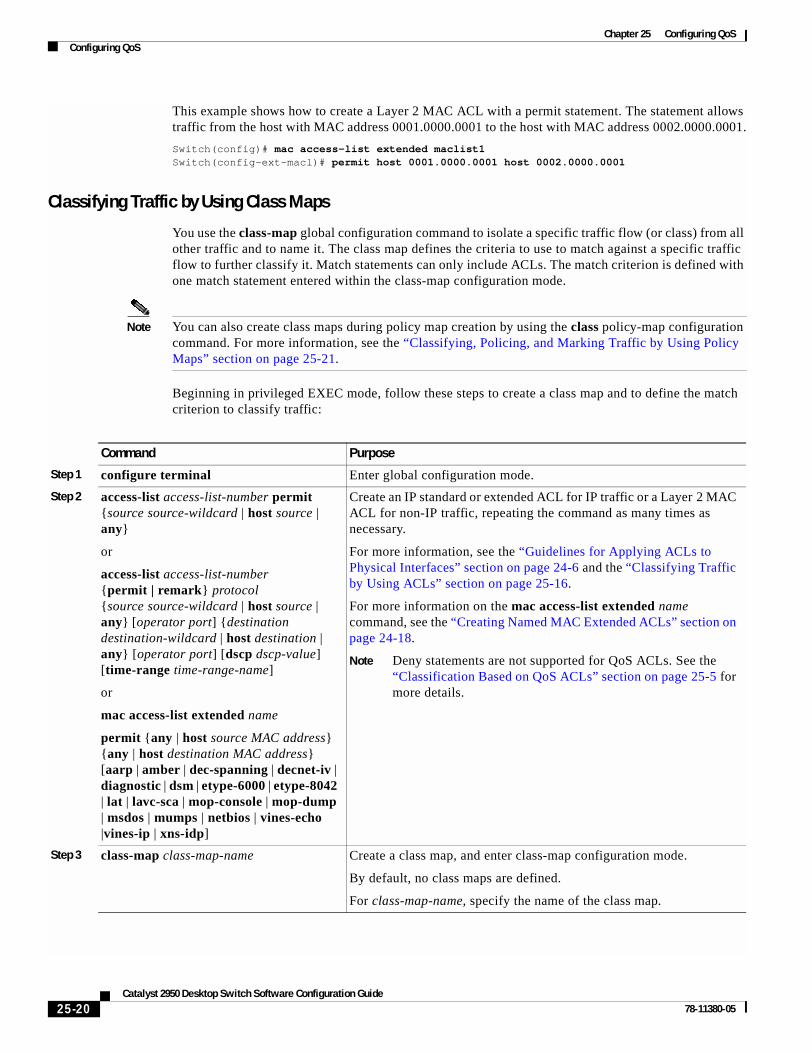
Chapter 25 Configuring QoSConfiguring QoS
This example shows how to create a Layer 2 MAC ACL with a permit statement. The statement allows traffic from the host with MAC address 0001.0000.0001 to the host with MAC address 0002.0000.0001.
Switch(config)# mac access-list extended maclist1Switch(config-ext-macl)# permit host 0001.0000.0001 host 0002.0000.0001
Classifying Traffic by Using Class Maps
You use the class-map global configuration command to isolate a specific traffic flow (or class) from all other traffic and to name it. The class map defines the criteria to use to match against a specific traffic flow to further classify it. Match statements can only include ACLs. The match criterion is defined with one match statement entered within the class-map configuration mode.
Note You can also create class maps during policy map creation by using the class policy-map configuration command. For more information, see the “Classifying, Policing, and Marking Traffic by Using Policy Maps” section on page 25-21.
Beginning in privileged EXEC mode, follow these steps to create a class map and to define the match criterion to classify traffic:
Command Purpose
Step 1 configure terminal Enter global configuration mode.
Step 2 access-list access-list-number permit {source source-wildcard | host source | any}
or
access-list access-list-number {permit | remark} protocol {source source-wildcard | host source | any} [operator port] {destination destination-wildcard | host destination | any} [operator port] [dscp dscp-value] [time-range time-range-name]
or
mac access-list extended name
permit {any | host source MAC address} {any | host destination MAC address} [aarp | amber | dec-spanning | decnet-iv | diagnostic | dsm | etype-6000 | etype-8042 | lat | lavc-sca | mop-console | mop-dump | msdos | mumps | netbios | vines-echo |vines-ip | xns-idp]
Create an IP standard or extended ACL for IP traffic or a Layer 2 MAC ACL for non-IP traffic, repeating the command as many times as necessary.
For more information, see the “Guidelines for Applying ACLs to Physical Interfaces” section on page 24-6 and the “Classifying Traffic by Using ACLs” section on page 25-16.
For more information on the mac access-list extended name command, see the “Creating Named MAC Extended ACLs” section on page 24-18.
Note Deny statements are not supported for QoS ACLs. See the “Classification Based on QoS ACLs” section on page 25-5 for more details.
Step 3 class-map class-map-name Create a class map, and enter class-map configuration mode.
By default, no class maps are defined.
For class-map-name, specify the name of the class map.
25-20Catalyst 2950 Desktop Switch Software Configuration Guide
78-11380-05

Chapter 25 Configuring QoSConfiguring QoS
To delete an existing class map, use the no class-map class-map-name global configuration command. To remove a match criterion, use the no match {access-group acl-index | name acl-name | ip dscp} class-map configuration command.
This example shows how to configure the class map called class1. The class1 has one match criterion, which is an ACL called 103.
Switch(config)# access-list 103 permit any any tcp eq 80 Switch(config)# class-map class1Switch(config-cmap)# match access-group 103Switch(config-cmap)# endSwitch#
Classifying, Policing, and Marking Traffic by Using Policy Maps
A policy map specifies which traffic class to act on. Actions can include trusting the CoS or DSCP values in the traffic class; setting a specific DSCP value in the traffic class; and specifying the traffic bandwidth limitations for each matched traffic class (policer) and the action to take when the traffic is out of profile (marking).
A policy map also has these characteristics:
• A policy map can contain multiple class statements, each with different match criteria and policers.
• A separate policy-map class can exist for each type of traffic received through an interface.
You can attach only one policy map per interface in the input direction.
Step 4 match {access-group acl-index | access-group name acl-name | ip dscp dscp-list}
Define the match criterion to classify traffic.
By default, no match criterion is supported.
Only one match criterion per class map is supported, and only one ACL per class map is supported.
For access-group acl-index or access-group name acl-name, specify the number or name of the ACL created in Step 3.
For ip dscp dscp-list, enter a list of up to eight IP DSCP values for each match statement to match against incoming packets. Separate each value with a space. The supported DSCP values are 0, 8, 10, 16, 18, 24, 26, 32, 34, 40, 46, 48, and 56.
Step 5 end Return to privileged EXEC mode.
Step 6 show class-map [class-map-name] Verify your entries.
Step 7 copy running-config startup-config (Optional) Save your entries in the configuration file.
Command Purpose
25-21Catalyst 2950 Desktop Switch Software Configuration Guide
78-11380-05

Chapter 25 Configuring QoSConfiguring QoS
Beginning in privileged EXEC mode, follow these steps to create a policy map:
Command Purpose
Step 1 configure terminal Enter global configuration mode.
Step 2 access-list access-list-number permit {source source-wildcard | host source | any}
or
access-list access-list-number {permit | remark} protocol {source source-wildcard | host source | any} [operator port] {destination destination-wildcard | host destination | any} [operator port] [dscp dscp-value] [time-range time-range-name]
or
mac access-list extended name
permit {any | host source MAC address} {any | host destination MAC address} [aarp | amber | appletalk |dec-spanning | decnet-iv | diagnostic | dsm | etype-6000 | etype-8042 | lat | lavc-sca | mop-console | mop-dump | msdos | mumps | netbios | vines-echo |vines-ip | xns-idp]
Create an IP standard or extended ACL for IP traffic or a Layer 2 MAC ACL for non-IP traffic, repeating the command as many times as necessary.
For more information, see the “Classifying Traffic by Using ACLs” section on page 25-16.
Note Deny statements are not supported for QoS ACLs. See the “Classification Based on QoS ACLs” section on page 25-5 for more details.
For more information on the mac access-list extended name command, see the “Creating Named MAC Extended ACLs” section on page 24-18.
Step 3 policy-map policy-map-name Create a policy map by entering the policy map name, and enter policy-map configuration mode.
By default, no policy maps are defined.
The default behavior of a policy map is to set the DSCP to 0 if the packet is an IP packet and to set the CoS to 0 if the packet is tagged. No policing is performed.
Step 4 class class-map-name [access-group name acl-index-or-name]
Define a traffic classification, and enter policy-map class configuration mode.
By default, no policy map class maps are defined.
If a traffic class has already been defined by using the class-map global configuration command, specify its name for class-map-name in this command.
For access-group name acl-index-or-name, specify the number or name of the ACL created in Step 2.
Note In a policy map, the class named class-default is not supported. The switch does not filter traffic based on the policy map defined by the class class-default policy-map configuration command.
25-22Catalyst 2950 Desktop Switch Software Configuration Guide
78-11380-05

Chapter 25 Configuring QoSConfiguring QoS
To delete an existing policy map, use the no policy-map policy-map-name global configuration command. To delete an existing class map, use the no class class-map-name policy-map configuration command. To remove an assigned DSCP value, use the no set ip dscp new-dscp policy-map configuration command. To remove an existing policer, use the no police rate-bps burst-byte [exceed-action {drop | dscp dscp-value}] policy-map configuration command. To remove the policy map and interface association, use the no service-policy input policy-map-name interface configuration command.
This example shows how to create a policy map and attach it to an ingress interface. In the configuration, the IP standard ACL permits traffic from network 10.1.0.0. For traffic matching this classification, the DSCP value in the incoming packet is trusted. If the matched traffic exceeds an average traffic rate of 5000000 bps and a normal burst size of 8192 bytes, its DSCP is marked down to a value of 10 and sent.
Step 5 set {ip dscp new-dscp} Classify IP traffic by setting a new value in the packet.
For ip dscp new-dscp, enter a new DSCP value to be assigned to the classified traffic. The supported DSCP values are 0, 8, 10, 16, 18, 24, 26, 32, 34, 40, 46, 48, and 56.
Step 6 police rate-bps burst-byte [exceed-action {drop | dscp dscp-value}]
Define a policer for the classified traffic.
You can configure up to 60 policers on ingress Gigabit-capable Ethernet ports and up to 6 policers on ingress 10/100 Ethernet ports.
For rate-bps, specify average traffic rate in bits per second (bps). The range is 1 Mbps to 100 Mbps for 10/100 Ethernet ports and 8 Mbps to 1000 Mbps for the Gigabit-capable Ethernet ports.
For burst-byte, specify the normal burst size in bytes. The values supported on the 10/100 ports are 4096, 8192, 16384, 32768, and 65536. The values supported on the Gigabit-capable Ethernet ports are 4096, 8192, 16348, 32768, 65536, 131072, 262144, and 524288.
(Optional) Specify the action to take when the rates are exceeded. Use the exceed-action drop keywords to drop the packet. Use the exceed-action dscp dscp-value keywords to mark down the DSCP value and send the packet.
Step 7 exit Return to policy-map configuration mode.
Step 8 exit Return to global configuration mode.
Step 9 interface interface-id Enter interface configuration mode, and specify the interface to attach to the policy map.
Valid interfaces include physical interfaces.
Step 10 service-policy input policy-map-name Apply specified policy map to the input of a particular interface.
Only one policy map per interface per direction is supported.
Step 11 end Return to privileged EXEC mode.
Step 12 show policy-map [policy-map-name class class-name]
Verify your entries.
Step 13 copy running-config startup-config (Optional) Save your entries in the configuration file.
Command Purpose
25-23Catalyst 2950 Desktop Switch Software Configuration Guide
78-11380-05

Chapter 25 Configuring QoSConfiguring QoS
Switch(config)# access-list 1 permit 10.1.0.0 0.0.255.255Switch(config)# class-map ipclass1Switch(config-cmap)# match access-group 1Switch(config-cmap)# exitSwitch(config)# policy-map flow1tSwitch(config-pmap)# class ipclass1Switch(config-pmap-c)# police 5000000 8192 exceed-action dscp 10Switch(config-pmap-c)# exitSwitch(config-pmap)# exitSwitch(config)# interface gigabitethernet0/1Switch(config-if)# switchport mode accessSwitch(config-if)# service-policy input flow1t
This example shows how to create a Layer 2 MAC ACL with two permit statements and attach it to an ingress interface. The first permit statement allows traffic from the host with MAC address 0001.0000.0001 destined for the host with MAC address 0002.0000.0001.
Switch(config)# mac access-list extended maclist1Switch(config-ext-mac)# permit host 0001.0000.0001 host 0002.0000.0001 Switch(config-ext-mac)# exitSwitch(config)# mac access-list extended maclist2Switch(config-ext-mac)# permit host 0001.0000.0003 host 0002.0000.0003 Switch(config-ext-mac)# exitSwitch(config)# class-map macclass1Switch(config-cmap)# match access-group name maclist1Switch(config-cmap)# exitSwitch(config)# policy-map macpolicy1Switch(config-pmap)# class macclass1Switch(config-pmap-c)# set ip dscp 56Switch(config-pmap-c)# exitSwitch(config-pmap)# class macclass2 maclist2Switch(config-pmap-c)# set ip dscp 48Switch(config-pmap-c)# exitSwitch(config-pmap)# exitSwitch(config)# interface gigabitethernet0/1Switch(config-if)# switchport mode trunkSwitch(config-if)# mls qos trust cosSwitch(config-if)# service-policy input macpolicy1
Configuring CoS Maps
Note This feature is available only if your switch is running the EI.
This section describes how to configure the CoS maps:
• Configuring the CoS-to-DSCP Map, page 25-25
• Configuring the DSCP-to-CoS Map, page 25-26
All the maps are globally defined.
25-24Catalyst 2950 Desktop Switch Software Configuration Guide
78-11380-05

Chapter 25 Configuring QoSConfiguring QoS
Configuring the CoS-to-DSCP Map
You use the CoS-to-DSCP map to map CoS values in incoming packets to a DSCP value that QoS uses internally to represent the priority of the traffic.
Table 25-3 shows the default CoS-to-DSCP map.
If these values are not appropriate for your network, you need to modify them.
Beginning in privileged EXEC mode, follow these steps to modify the CoS-to-DSCP map:
To return to the default map, use the no mls qos map cos-dscp global configuration command.
This example shows how to modify and display the CoS-to-DSCP map:
Switch# configure terminalSwitch(config)# mls qos map cos-dscp 8 8 8 8 24 32 56 56Switch(config)# endSwitch# show mls qos maps cos-dscp
Cos-dscp map: cos: 0 1 2 3 4 5 6 7 -------------------------------- dscp: 8 8 8 8 24 32 56 56
Table 25-3 Default CoS-to-DSCP Map
CoS value 0 1 2 3 4 5 6 7
DSCP value 0 8 16 24 32 40 48 56
Command Purpose
Step 1 configure terminal Enter global configuration mode.
Step 2 mls qos map cos-dscp dscp1...dscp8 Modify the CoS-to-DSCP map.
For dscp1...dscp8, enter 8 DSCP values that correspond to CoS values 0 to 7. Separate each DSCP value with a space.
The supported DSCP values are 0, 8, 10, 16, 18, 24, 26, 32, 34, 40, 46, 48, and 56.
Step 3 end Return to privileged EXEC mode.
Step 4 show mls qos maps cos-dscp Verify your entries.
Step 5 copy running-config startup-config (Optional) Save your entries in the configuration file.
25-25Catalyst 2950 Desktop Switch Software Configuration Guide
78-11380-05

Chapter 25 Configuring QoSConfiguring QoS
Configuring the DSCP-to-CoS Map
You use the DSCP-to-CoS map to map DSCP values in incoming packets to a CoS value, which is used to select one of the four egress queues.
The switch supports these DSCP values: 0, 8, 10, 16, 18, 24, 26, 32, 34, 40, 46, 48, and 56.
Table 25-4 shows the default DSCP-to-CoS map.
If these values are not appropriate for your network, you need to modify them.
Beginning in privileged EXEC mode, follow these steps to modify the DSCP-to-CoS map:
To return to the default map, use the no mls qos map dscp-cos global configuration command.
This example shows how the DSCP values 26 and 48 are mapped to CoS value 7. For the remaining DSCP values, the DSCP-to-CoS mapping is the default.
Switch(config)# mls qos map dscp-cos 26 48 to 7Switch(config)# exit
Switch# show mls qos maps dscp-cos
Dscp-cos map: dscp: 0 8 10 16 18 24 26 32 34 40 46 48 56 ----------------------------------------------- cos: 0 1 1 2 2 3 7 4 4 5 5 7 7
Table 25-4 Default DSCP-to-CoS Map
DSCP values 0 8, 10 16, 18 24, 26 32, 34 40, 46 48 56
CoS values 0 1 2 3 4 5 6 7
Command Purpose
Step 1 configure terminal Enter global configuration mode.
Step 2 mls qos map dscp-cos dscp-list to cos Modify the DSCP-to-CoS map.
For dscp-list, enter up to 13 DSCP values separated by spaces. Then enter the to keyword.
For cos, enter the CoS value to which the DSCP values correspond.
The supported DSCP values are 0, 8, 10, 16, 18, 24, 26, 32, 34, 40, 46, 48, and 56. The CoS range is 0 to 7.
Step 3 end Return to privileged EXEC mode.
Step 4 show mls qos maps dscp-cos Verify your entries.
Step 5 copy running-config startup-config (Optional) Save your entries in the configuration file.
25-26Catalyst 2950 Desktop Switch Software Configuration Guide
78-11380-05

Chapter 25 Configuring QoSConfiguring QoS
Configuring CoS and WRR
Note This feature is supported by both the EI and SI.
This section describes how to configure CoS priorities and weighted round-robin (WRR):
• Configuring CoS Priority Queues, page 25-27
• Configuring WRR, page 25-27
Configuring CoS Priority Queues
Beginning in privileged EXEC mode, follow these steps to configure the CoS priority queues:
To disable the new CoS settings and return to default settings, use the no wrr-queue cos-map global configuration command.
Configuring WRR
Beginning in privileged EXEC mode, follow these steps to configure the WRR priority:
Command Purpose
Step 1 configure terminal Enter global configuration mode.
Step 2 wrr-queue cos-map qid cos1..cosn Specify the queue ID of the CoS priority queue. (Ranges are 1 to 4 where 1 is the lowest CoS priority queue.)
Specify the CoS values that are mapped to the queue id.
Default values are as follows:
CoS Value CoS Priority Queues
0, 1 1
2, 3 2
4, 5 3
6, 7 4
Step 3 end Return to privileged EXEC mode.
Step 4 show wrr-queue cos-map Display the mapping of the CoS priority queues.
Command Purpose
Step 1 configure terminal Enter global configuration mode.
Step 2 wrr-queue bandwidth weight1...weight4
Assign WRR weights to the four CoS queues. (Ranges for the WRR values are 1 to 255.)
Step 3 end Return to privileged EXEC mode.
Step 4 show wrr-queue bandwidth Display the WRR bandwidth allocation for the CoS priority queues.
25-27Catalyst 2950 Desktop Switch Software Configuration Guide
78-11380-05

Chapter 25 Configuring QoSDisplaying QoS Information
To disable the WRR scheduler and enable the strict priority scheduler, use the no wrr-queue bandwidth global configuration command.
Displaying QoS InformationTo display QoS information, use one or more of the privileged EXEC commands in Table 25-5:
Table 25-5 Commands for Displaying QoS Information
Command Purpose
show class-map [class-map-name]1
1. Available only on a switch running the EI.
Display QoS class maps, which define the match criteria to classify traffic.
show policy-map [policy-map-name [class class-name]]1 Display QoS policy maps, which define classification criteria for incoming traffic.
show mls qos maps [cos-dscp | dscp-cos]1 Display QoS mapping information. Maps are used to generate an internal DSCP value, which represents the priority of the traffic.
show mls qos interface [interface-id] [policers]1 Display QoS information at the interface level, including the configuration of the egress queues and the CoS-to-egress-queue map, which interfaces have configured policers, and ingress and egress statistics (including the number of bytes dropped).2
2. You can define up to 13 DSCP values for which byte or packet statistics are gathered by hardware by using the show mls qos interface statistics privileged EXEC command.
show mls masks [qos | security]1 Display details regarding the masks3 used for QoS and security ACLs.
3. Access control parameters are called masks in the switch CLI commands and output.
show wrr-queue cos-map Display the mapping of the CoS priority queues.
show wrr-queue bandwidth Display the WRR bandwidth allocation for the CoS priority queues.
25-28Catalyst 2950 Desktop Switch Software Configuration Guide
78-11380-05

Chapter 25 Configuring QoSQoS Configuration Examples
QoS Configuration Examples
Note These examples are applicable only if your switch is running the EI.
This section provides a QoS migration path to help you quickly implement QoS features based on your existing network and planned changes to your network, as shown in Figure 25-4. It contains this information:
• QoS Configuration for the Existing Wiring Closet, page 25-30
• QoS Configuration for the Intelligent Wiring Closet, page 25-30
Figure 25-4 QoS Configuration Example Network
Cisco router
Existing wiring closetCatalyst 2900 and 3500 XL
switches
Intelligent wiring closetCatalyst 2950 switches
To Internet
Catalyst 3550-12G switch
Gigabit Ethernet 0/5
Gigabit Ethernet 0/2
GigabitEthernet
0/2 GigabitEthernet0/1
Trunklink
Gigabit Ethernet 0/1
Trunklink
Endstations
Video server172.20.10.16
6528
8
25-29Catalyst 2950 Desktop Switch Software Configuration Guide
78-11380-05

Chapter 25 Configuring QoSQoS Configuration Examples
QoS Configuration for the Existing Wiring ClosetThe existing wiring closet in Figure 25-4 consists of existing Catalyst 2900 XL and 3500 XL switches. These switches are running IOS release 12.0(5)XP or later, which supports the QoS-based IEEE 802.1P CoS values. QoS classifies frames by assigning priority-indexed CoS values to them and gives preference to higher-priority traffic.
Recall that on the Catalyst 2900 and 3500 XL switches, you can classify untagged (native) Ethernet frames at the ingress ports by setting a default CoS priority (switchport priority default default-priority-id interface configuration command) for each port. For IEEE 802.1Q frames with tag information, the priority value from the header frame is used. On the Catalyst 3524-PWR XL and 3548 XL switches, you can override this priority with the default value by using the switchport priority default override interface configuration command. For Catalyst 2950 and Catalyst 2900 XL switches and other 3500 XL models that do not have the override feature, the Catalyst 3550-12T switch at the distribution layer can override the 802.1P CoS value by using the mls qos cos override interface configuration command.
For the Catalyst 2900 and 3500 XL switches, CoS configures each transmit port (the egress port) with a normal-priority transmit queue and a high-priority transmit queue, depending on the frame tag or the port information. Frames in the normal-priority queue are forwarded only after frames in the high-priority queue are forwarded. Frames that have 802.1P CoS values of 0 to 3 are placed in the normal-priority transmit queue while frames with CoS values of 4 to 7 are placed in the expedite (high-priority) queue.
QoS Configuration for the Intelligent Wiring ClosetThe intelligent wiring closet in Figure 25-4 is composed of Catalyst 2950 switches. One of the switches is connected to a video server, which has an IP address of 172.20.10.16.
The object of this example is to prioritize the video traffic over all other traffic. To do so, a DSCP of 46 is assigned to the video traffic. This traffic is stored in queue 4, which is serviced more frequently than the other queues.
Beginning in privileged EXEC mode, follow these steps to configure the switch to prioritize video packets over all other traffic:
Command Purpose
Step 1 configure terminal Enter global configuration mode.
Step 2 access-list 1 permit 172.20.10.16 Define an IP standard ACL, and permit traffic from the video server at 172.20.10.16.
Step 3 class-map videoclass Create a class map called videoclass, and enter class-map configuration mode.
Step 4 match access-group 1 Define the match criterion by matching the traffic specified by ACL 1.
Step 5 exit Return to global configuration mode.
Step 6 policy-map videopolicy Create a policy map called videopolicy, and enter policy-map configuration mode.
Step 7 class videoclass Specify the class on which to act, and enter policy-map class configuration mode.
Step 8 set ip dscp 46 For traffic matching ACL 1, set the DSCP of incoming packets to 46.
25-30Catalyst 2950 Desktop Switch Software Configuration Guide
78-11380-05

Chapter 25 Configuring QoSQoS Configuration Examples
Step 9 police 5000000 8192 exceed-action drop Define a policer for the classified video traffic to drop traffic that exceeds 5-Mbps average traffic rate with an 8192-byte burst size.
Step 10 exit Return to policy-map configuration mode.
Step 11 exit Return to global configuration mode.
Step 12 interface gigabitethernet0/1 Enter interface configuration mode, and specify the ingress interface.
Step 13 service-policy input videopolicy Apply the policy to the ingress interface.
Step 14 exit Return to global configuration mode.
Step 15 wrr-queue bandwidth 1 2 3 4 Assign a higher WRR weight to queue 4.
Step 16 wrr-queue cos-map 4 6 7 Configure the CoS-to-egress-queue map so that CoS values 6 and 7 select queue 4.
Step 17 end Return to privileged EXEC mode.
Step 18 show class-map videoclass
show policy-map videopolicy
show mls qos maps [cos-dscp | dscp-cos]
Verify your entries.
Step 19 copy running-config startup-config (Optional) Save your entries in the configuration file.
Command Purpose
25-31Catalyst 2950 Desktop Switch Software Configuration Guide
78-11380-05

Chapter 25 Configuring QoSQoS Configuration Examples
25-32Catalyst 2950 Desktop Switch Software Configuration Guide
78-11380-05

Catalyst 2950 Deskto78-11380-05
C H A P T E R 26
Configuring EtherChannelsThis chapter describes how to configure EtherChannel on Layer 2 interfaces. EtherChannel provides fault-tolerant high-speed links between switches, routers, and servers. You can use it to increase the bandwidth between the wiring closets and the data center, and you can deploy it anywhere in the network where bottlenecks are likely to occur. EtherChannel provides automatic recovery for the loss of a link by redistributing the load across the remaining links. If a link fails, EtherChannel redirects traffic from the failed link to the remaining links in the channel without intervention.
Note For complete syntax and usage information for the commands used in this chapter, refer to the command reference for this release.
This chapter consists of these sections:
• Understanding EtherChannels, page 26-1
• Configuring EtherChannels, page 26-7
• Displaying EtherChannel and PAgP Status, page 26-11
Understanding EtherChannelsAn EtherChannel consists of individual Fast Ethernet or Gigabit Ethernet links bundled into a single logical link as shown in Figure 26-1. The EtherChannel provides full-duplex bandwidth up to 800 Mbps (Fast EtherChannel) or 2 Gbps (Gigabit EtherChannel) between your switch and another switch or host.
26-1p Switch Software Configuration Guide

Chapter 26 Configuring EtherChannelsUnderstanding EtherChannels
Figure 26-1 Typical EtherChannel Configuration
Each EtherChannel can consist of up to eight compatibly configured Ethernet interfaces. All interfaces in each EtherChannel must be the same speed, and all must be configured as Layer 2 interfaces.
Note The network device to which your switch is connected can impose its own limits on the number of interfaces in the EtherChannel. For Catalyst 2950 switches, the number of EtherChannels is limited to six with eight ports per EtherChannel.
If a link within an EtherChannel fails, traffic previously carried over that failed link changes to the remaining links within the EtherChannel. A trap is sent for a failure, identifying the switch, the EtherChannel, and the failed link. Inbound broadcast and multicast packets on one link in an EtherChannel are blocked from returning on any other link of the EtherChannel.
Understanding Port-Channel InterfacesWhen you create an EtherChannel for Layer 2 interfaces, a logical interface is dynamically created. You then manually assign an interface to the EtherChannel by using the channel-group interface configuration command as shown in Figure 26-2.
Each EtherChannel has a logical port-channel interface numbered from 1 to. 6.
Catalyst 8500, 6000,5500, or 4000series switch
Catalyst 3550-12Tswitch
Gigabit EtherChannel
Catalyst 3550-12Tswitch
Workstations
10/100Switched
links
7461
8
Catalyst 2950G-24switch
Workstations
10/100Switched
links
1000BASE-X 1000BASE-X
26-2Catalyst 2950 Desktop Switch Software Configuration Guide
78-11380-05

Chapter 26 Configuring EtherChannelsUnderstanding EtherChannels
Figure 26-2 Relationship of Physical Ports, Logical Port Channels, and Channel Groups
After you configure an EtherChannel, configuration changes applied to the port-channel interface apply to all the physical interfaces assigned to the port-channel interface. Configuration changes applied to the physical interface affect only the interface where you apply the configuration. To change the parameters of all ports in an EtherChannel, apply configuration commands to the port-channel interface, for example, spanning-tree commands or commands to configure a Layer 2 EtherChannel as a trunk.
Understanding the Port Aggregation ProtocolThe Port Aggregation Protocol (PAgP) facilitates the automatic creation of EtherChannels by exchanging packets between Ethernet interfaces. By using PAgP, the switch learns the identity of partners capable of supporting PAgP and learns the capabilities of each interface. It then dynamically groups similarly configured interfaces into a single logical link (channel or aggregate port); these interfaces are grouped based on hardware, administrative, and port parameter constraints. For example, PAgP groups the interfaces with the same speed, duplex mode, native VLAN, VLAN range, and trunking status and type. After grouping the links into an EtherChannel, PAgP adds the group to the spanning tree as a single switch port.
6563
6
SYSTRPS
DUPLX
MODE
SPEEDUTIL
STAT
Catalyst 2950 SERIES
1X
2X
11X
12X
1 2 3 4 5 6 7 8 9 10 11 12
1
13X
14X
23X
24X
13 14 15 16 17 18 19 20 21 22 23 24
2
10/100 ports
GBIC moduleslots
Physicalports
Logicalport-channel
Channel-groupbinding
Logicalport-channel
26-3Catalyst 2950 Desktop Switch Software Configuration Guide
78-11380-05

Chapter 26 Configuring EtherChannelsUnderstanding EtherChannels
PAgP Modes
Table 26-1 shows the user-configurable EtherChannel modes for the channel-group interface configuration command: on, auto, and desirable. Switch interfaces exchange PAgP packets only with partner interfaces configured in the auto or desirable modes; interfaces configured in the on mode do not exchange PAgP packets.
Both the auto and desirable modes allow interfaces to negotiate with partner interfaces to determine if they can form an EtherChannel based on criteria such as interface speed and, for Layer 2 EtherChannels, trunking state and VLAN numbers.
Interfaces can form an EtherChannel when they are in different PAgP modes as long as the modes are compatible. For example:
• An interface in the desirable mode can form an EtherChannel with another interface that is in the desirable or auto mode.
• An interface in the auto mode can form an EtherChannel with another interface in the desirable mode.
An interface in the auto mode cannot form an EtherChannel with another interface that is also in the auto mode because neither interface starts PAgP negotiation.
An interface in the on mode that is added to a port channel is forced to have the same characteristics as the already existing on mode interfaces in the channel.
Caution You should exercise care when setting the mode to on (manual configuration). All ports configured in the on mode are bundled in the same group and are forced to have similar characteristics. If the group is misconfigured, packet loss or spanning-tree loops might occur.
If your switch is connected to a partner that is PAgP-capable, you can configure the switch interface for nonsilent operation by using the non-silent keyword. If you do not specify non-silent with the auto or desirable mode, silent mode is assumed.
The silent mode is used when the switch is connected to a device that is not PAgP-capable and seldom, if ever, sends packets. An example of a silent partner is a file server or a packet analyzer that is not generating traffic. In this case, running PAgP on a physical port connected to a silent partner prevents that switch port from ever becoming operational; however, the silent setting allows PAgP to operate, to attach the interface to a channel group, and to use the interface for transmission.
Table 26-1 EtherChannel Modes
Mode Description
auto Places an interface into a passive negotiating state, in which the interface responds to PAgP packets it receives but does not start PAgP packet negotiation. This setting minimizes the transmission of PAgP packets.
desirable Places an interface into an active negotiating state, in which the interface starts negotiations with other interfaces by sending PAgP packets.
on Forces the interface to channel without PAgP. With the on mode, a usable EtherChannel exists only when an interface group in the on mode is connected to another interface group in the on mode.
26-4Catalyst 2950 Desktop Switch Software Configuration Guide
78-11380-05

Chapter 26 Configuring EtherChannelsUnderstanding EtherChannels
Physical Learners and Aggregate-Port Learners
Network devices are classified as PAgP physical learners or aggregate-port learners. A device is a physical learner if it learns addresses by physical ports and directs transmissions based on that knowledge. A device is an aggregate-port learner if it learns addresses by aggregate (logical) ports.
When a device and its partner are both aggregate-port learners, they learn the address on the logical port-channel. The device sends packets to the source by using any of the interfaces in the EtherChannel. With aggregate-port learning, it is not important on which physical port the packet arrives.
The switch uses source-MAC address distribution for a channel if it is connected to a physical learner even if the user configures destination-MAC address distribution.
These frame distribution mechanisms are possible for frame transmission:
• Port selection based on the source-MAC address of the packet
• Port selection based on the destination- MAC address of the packet
The switch supports up to eight ports in a PAgP group.
PAgP Interaction with Other Features
The Dynamic Trunking Protocol (DTP) and Cisco Discovery Protocol (CDP) send and receive packets over the physical interfaces in the EtherChannel. Trunk ports send and receive PAgP protocol data units (PDUs) on the lowest numbered VLAN.
Spanning tree sends packets over a single physical interface in the EtherChannel. Spanning tree regards the EtherChannel as one port.
PAgP sends and receives PAgP PDUs only from interfaces that are up and have PAgP enabled for the auto or desirable mode.
Understanding Load Balancing and Forwarding MethodsEtherChannel balances the traffic load across the links in a channel by reducing part of the binary pattern formed from the addresses in the frame to a numerical value that selects one of the links in the channel. EtherChannel load balancing can use either source-MAC or destination-MAC address forwarding.
With source-MAC address forwarding, when packets are forwarded to an EtherChannel, they are distributed across the ports in the channel based on the source-MAC address of the incoming packet. Therefore, to provide load balancing, packets from different hosts use different ports in the channel, but packets from the same host use the same port in the channel (and the MAC address learned by the switch does not change).
With destination-MAC address forwarding, when packets are forwarded to an EtherChannel, they are distributed across the ports in the channel based on the destination host’s MAC address of the incoming packet. Therefore, packets to the same destination are forwarded over the same port, and packets to a different destination are sent on a different port in the channel. You configure the load balancing and forwarding method by using the port-channel load-balance global configuration command.
In Figure 26-3, an EtherChannel of four workstations communicates with a router. Because the router is a single-MAC-address device, source-based forwarding on the switch EtherChannel ensures that the switch uses all available bandwidth to the router. The router is configured for destination-based forwarding because the large number of workstations ensures that the traffic is evenly distributed from the router EtherChannel.
26-5Catalyst 2950 Desktop Switch Software Configuration Guide
78-11380-05

Chapter 26 Configuring EtherChannelsUnderstanding EtherChannels
Use the option that provides the greatest variety in your configuration. For example, if the traffic on a channel is going only to a single MAC address, using the destination-MAC address always chooses the same link in the channel; using source addresses or IP addresses might result in better load balancing.
Figure 26-3 Load Distribution and Forwarding Methods
7461
9
Cisco routerwith destination-basedforwarding enabled
EtherChannel
Catalyst 2950 or 3550 switchwith source-basedforwarding enabled
26-6Catalyst 2950 Desktop Switch Software Configuration Guide
78-11380-05

Chapter 26 Configuring EtherChannelsConfiguring EtherChannels
Configuring EtherChannelsThese sections describe how to configure EtherChannel interfaces:
• Default EtherChannel Configuration, page 26-7
• EtherChannel Configuration Guidelines, page 26-8
• Configuring Layer 2 EtherChannels, page 26-8
• Configuring EtherChannel Load Balancing, page 26-10
• Configuring the PAgP Learn Method and Priority, page 26-11
Note Make sure that the interfaces are correctly configured (see the “EtherChannel Configuration Guidelines” section on page 26-8).
Note After you configure an EtherChannel, configuration changes applied to the port-channel interface apply to all the physical interfaces assigned to the port-channel interface, and configuration changes applied to the physical interface affect only the interface where you apply the configuration.
Default EtherChannel ConfigurationTable 26-2 shows the default EtherChannel configuration.
Table 26-2 Default EtherChannel Configuration
Feature Default Setting
Channel groups None assigned.
PAgP mode No default.
PAgP learn method Aggregate-port learning on all interfaces.
PAgP priority 128 on all interfaces. (Changing this value has no effect.)
Load balancing Load distribution on the switch is based on the source-MAC address of the incoming packet.
26-7Catalyst 2950 Desktop Switch Software Configuration Guide
78-11380-05

Chapter 26 Configuring EtherChannelsConfiguring EtherChannels
EtherChannel Configuration GuidelinesIf improperly configured, some EtherChannel interfaces are automatically disabled to avoid network loops and other problems. Follow these guidelines to avoid configuration problems:
• Configure an EtherChannel with up to eight Ethernet interfaces of the same type.
Note Do not configure a GigaStack GBIC port as part of an EtherChannel.
• Configure all interfaces in an EtherChannel to operate at the same speeds and duplex modes.
• Enable all interfaces in an EtherChannel. An interface in an EtherChannel that is disabled by using the shutdown interface configuration command is treated as a link failure, and its traffic is transferred to one of the remaining interfaces in the EtherChannel.
• When a group is first created, all ports follow the parameters set for the first port to be added to the group. If you change the configuration of one of these parameters, you must also make the changes to all ports in the group:
– Allowed-VLAN list
– Spanning-tree path cost for each VLAN
– Spanning-tree port priority for each VLAN
– Spanning-tree Port Fast setting
• If you configure Switch Port Analyzer (SPAN) on a port that is a member of the EtherChannel, it leaves the EtherChannel.
• Do not configure a port that belongs to an EtherChannel port group as a secure port.
• Before enabling 802.1X on the port, you must first remove it from the EtherChannel. If you try to enable 802.1X on an EtherChannel or on an active port in an EtherChannel, an error message appears, and 802.1X is not enabled. If you enable 802.1X on a not-yet active port of an EtherChannel, the port does not join the EtherChannel.
• Assign all interfaces in the EtherChannel to the same VLAN, or configure them as trunks.
• If you configure an EtherChannel from trunk interfaces, verify that the trunking mode (802.1Q) is the same on all the trunks. Inconsistent trunk modes on EtherChannel interfaces can have unexpected results.
• An EtherChannel supports the same allowed range of VLANs on all the interfaces in a trunking Layer 2 EtherChannel. If the allowed range of VLANs is not the same, the interfaces do not form an EtherChannel even when PAgP is set to the auto or desirable mode.
• Interfaces with different spanning-tree path costs can form an EtherChannel if they are otherwise compatibly configured. Setting different spanning-tree path costs does not, by itself, make interfaces incompatible for the formation of an EtherChannel.
Configuring Layer 2 EtherChannelsYou configure Layer 2 EtherChannels by configuring the Ethernet interfaces with the channel-group interface configuration command, which creates the port-channel logical interface.
Note Layer 2 interfaces must be connected and functioning for IOS to create port-channel interfaces.
26-8Catalyst 2950 Desktop Switch Software Configuration Guide
78-11380-05

Chapter 26 Configuring EtherChannelsConfiguring EtherChannels
Beginning in privileged EXEC mode, follow these steps to assign a Layer 2 Ethernet interface to a Layer 2 EtherChannel:
Command Purpose
Step 1 configure terminal Enter global configuration mode.
Step 2 interface interface-id Enter interface configuration mode, and specify a physical interface to configure.
Valid interfaces include physical interfaces.
Up to eight interfaces of the same type and speed can be configured for the same group.
Step 3 channel-group channel-group-number mode {auto [non-silent] | desirable [non-silent] | on}
Assign the interface to a channel group, and specify the PAgP mode. The default mode is auto silent.
For channel-group-number, the range is 1 to 6. Each EtherChannel can have of up to eight compatibly configured Ethernet interfaces.
For mode, select one of these keywords:
• auto—Enables PAgP only if a PAgP device is detected. It places an interface into a passive negotiating state, in which the interface responds to PAgP packets it receives but does not start PAgP packet negotiation.
• desirable—Unconditionally enables PAgP. It places an interface into an active negotiating state, in which the interface starts negotiations with other interfaces by sending PAgP packets.
• on—Forces the interface to channel without PAgP. With the on mode, a usable EtherChannel exists only when an interface group in the on mode is connected to another interface group in the on mode.
• non-silent—If your switch is connected to a partner that is PAgP-capable, you can configure the switch interface for nonsilent operation. You can configure an interface with the non-silent keyword for use with the auto or desirable mode. If you do not specify non-silent with the auto or desirable mode, silent is assumed. The silent setting is for connections to file servers or packet analyzers; this setting allows PAgP to operate, to attach the interface to a channel group, and to use the interface for transmission.
For information on compatible PAgP modes for the switch and its partner, see the “PAgP Modes” section on page 26-4.
Step 4 end Return to privileged EXEC mode.
Step 5 show running-config Verify your entries.
Step 6 copy running-config startup-config (Optional) Save your entries in the configuration file.
26-9Catalyst 2950 Desktop Switch Software Configuration Guide
78-11380-05

Chapter 26 Configuring EtherChannelsConfiguring EtherChannels
To remove an interface from the EtherChannel group, use the no channel-group interface configuration command. If you delete the EtherChannel by using the no interface port-channel global configuration command without removing the physical interfaces, the physical interfaces are shutdown. If you do not want the member physical interfaces to shut down, remove the physical interfaces before deleting the EtherChannel.
This example shows how to assign Gigabit Ethernet interfaces 0/1 and 0/2 with the PAgP mode desirable:
Switch# configure terminal Switch(config)# interface range gigabitethernet0/1 -2 Switch(config-if)# channel-group 5 mode desirable Switch(config-if)# end
Configuring EtherChannel Load BalancingThis section describes how to configure EtherChannel load balancing by using source-based or destination-based forwarding methods. For more information, see the “Understanding Load Balancing and Forwarding Methods” section on page 26-5.
Beginning in privileged EXEC mode, follow these steps to configure EtherChannel load balancing:
Command Purpose
Step 1 configure terminal Enter global configuration mode.
Step 2 port-channel load-balance {dst-mac | src-mac} Configure an EtherChannel load-balancing method.
The default is src-mac.
Select one of these keywords to determine the load-distribution method:
• dst-mac—Load distribution is based on the destination-host MAC address of the incoming packet. Packets to the same destination are sent on the same port, but packets to different destinations are sent on different ports in the channel.
• src-mac—Load distribution is based on the source-MAC address of the incoming packet. Packets from different hosts use different ports in the channel, but packets from the same host use the same port in the channel.
If the link partner to the switch is a physical learner, set the load-distribution method to one of these ways:
• If the channel-group interface configuration command is set to auto or desirable, the switch automatically uses the load distribution method based on the source-MAC address, regardless of the configured load-distribution method.
• If the channel-group interface configuration command is set to on, set the load-distribution method based on the source-MAC address by using the port-channel load-balance src-mac global configuration command.
Step 3 end Return to privileged EXEC mode.
26-10Catalyst 2950 Desktop Switch Software Configuration Guide
78-11380-05

Chapter 26 Configuring EtherChannelsDisplaying EtherChannel and PAgP Status
To return EtherChannel load balancing to the default configuration, use the no port-channel load-balance global configuration command.
Configuring the PAgP Learn Method and PriorityNetwork devices are classified as PAgP physical learners or aggregate-port learners. A device is a physical learner if it learns addresses by physical ports and directs transmissions based on that knowledge. A device is an aggregate-port learner if it learns addresses by aggregate ports.
For compatibility with Catalyst 1900 series switches, configure the Catalyst 2950 switches for source-MAC load distribution.
The Catalyst 2950 switch supports address learning only on aggregate ports even though the physical-port keyword is provided in the command-line interface (CLI). The pagp learn-method and the pagp port-priority interface configuration command have no effect on the switch hardware.
Note You should not set the learn method to physical-port because the switch is an aggregate-learning device.
If the link partner to the switch is a physical learner that has the channel-group interface configuration command set to auto or desirable, the switch automatically uses the load-distribution method based on the source MAC address, regardless of the configured load distribution method.
If the link partner to the Catalyst 2950 switch is a physical learner that has the channel-group interface configuration command set to on, set the load-distribution method based on the source MAC address by using the port-channel load-balance src-mac global configuration command.
Displaying EtherChannel and PAgP StatusYou can use the privileged EXEC commands described in Table 26-3 to display EtherChannel and PAgP status information:
For detailed information about the fields in the displays, refer to the command reference for this release.
Step 4 show etherchannel load-balance Verify your entries.
Step 5 copy running-config startup-config (Optional) Save your entries in the configuration file.
Command Purpose
Table 26-3 Commands for Displaying EtherChannel and PAgP Status
Command Description
show etherchannel [channel-group-number] {brief | detail | load-balance | port | port-channel | summary}
Displays EtherChannel information in a brief, detailed, and one-line summary form. Also displays the load-balance or frame-distribution scheme, port, and port-channel information.
show pagp [channel-group-number] {counters | internal | neighbor}1
1. You can clear PAgP channel-group information and traffic filters by using the clear pagp {channel-group-number [counters] | counters} privileged EXEC command.
Displays PAgP information such as traffic information, the internal PAgP configuration, and neighbor information.
26-11Catalyst 2950 Desktop Switch Software Configuration Guide
78-11380-05

Chapter 26 Configuring EtherChannelsDisplaying EtherChannel and PAgP Status
26-12Catalyst 2950 Desktop Switch Software Configuration Guide
78-11380-05

Catalyst 2950 Deskto78-11380-05
C H A P T E R 27
TroubleshootingThis chapter describes how to identify and resolve software problems related to the IOS software. Depending on the nature of the problem, you can use the command-line interface (CLI) or the Cluster Management Suite (CMS) to identify and solve problems. To identify and resolve Cisco-approved Course Wave Division Multiplexer (CWDM) Gigabit Interface Converter (GBIC) problems, you must have the enhanced software image (EI) installed on your switch.
Note For complete syntax and usage information for the commands used in this chapter, refer to the command reference for this release and the Cisco IOS Command Summary for Release 12.1.
This chapter consists of these sections:
• Using Recovery Procedures, page 27-1
• Preventing Autonegotiation Mismatches, page 27-8
• GBIC Module Security and Identification, page 27-8
• Using Debug Commands, page 27-8
• Using the crashinfo File, page 27-10
Using Recovery ProceduresThese recovery procedures require that you have physical access to the switch:
• Recovering from Corrupted Software, page 27-2
• Recovering from a Lost or Forgotten Password, page 27-2
• Recovering from a Command Switch Failure, page 27-4
• Recovering from Lost Member Connectivity, page 27-7
27-1p Switch Software Configuration Guide

Chapter 27 TroubleshootingUsing Recovery Procedures
Recovering from Corrupted SoftwareSwitch software can be corrupted during an upgrade, by downloading the wrong file to the switch, and by deleting the image file. In all of these cases, the switch does not pass the power-on self-test (POST), and there is no connectivity.
This procedure uses the XMODEM Protocol to recover from a corrupt or wrong image file. There are many software packages that support the XMODEM protocol, and this procedure is largely dependent on the emulation software you are using.
Step 1 Connect a PC with terminal-emulation software supporting the XMODEM Protocol to the switch console port.
Step 2 Set the line speed on the emulation software to 9600 baud.
Step 3 Disconnect the switch power cord.
Step 4 Reconnect the power cord to the switch.
The software image does not load. The switch starts in boot loader mode, which is indicated by the switch# prompt.
Step 5 Use the boot loader to enter commands, and start the transfer.
switch# copy xmodem: flash:image_filename.bin
Step 6 When the XMODEM request appears, use the appropriate command on the terminal-emulation software to start the transfer and to copy the software image to Flash memory.
Recovering from a Lost or Forgotten PasswordFollow these steps if you have forgotten or lost the switch password.
Step 1 Connect a terminal or PC with terminal emulation software to the console port. For more information, refer to the switch hardware installation guide.
Note You can configure your switch for Telnet by following the procedure in the “Accessing the CLI” section on page 2-9.
Step 2 Set the line speed on the emulation software to 9600 baud.
Step 3 Unplug the switch power cord.
27-2Catalyst 2950 Desktop Switch Software Configuration Guide
78-11380-05

Chapter 27 TroubleshootingUsing Recovery Procedures
Step 4 Press the Mode button, and at the same time, reconnect the power cord to the switch.
You can release the Mode button a second or two after the LED above port 1X goes off. Several lines of information about the software appear, as do instructions:
The system has been interrupted prior to initializing the flash file system. These commands will initialize the flash file system, and finish loading the operating system software:
flash_initload_helperboot
Step 5 Initialize the Flash file system:
switch# flash_init
Step 6 If you had set the console port speed to anything other than 9600, it has been reset to that particular speed. Change the emulation software line speed to match that of the switch console port.
Step 7 Load any helper files:
switch# load_helper
Step 8 Display the contents of Flash memory as in this example:
switch# dir flash:The switch file system is displayed:Directory of flash:/ 3 drwx 10176 Mar 01 2001 00:04:34 html 6 -rwx 2343 Mar 01 2001 03:18:16 config.text171 -rwx 1667997 Mar 01 2001 00:02:39 c2950-i6q412-mz.121-9.EA1.bin 7 -rwx 3060 Mar 01 2001 00:14:20 vlan.dat172 -rwx 100 Mar 01 2001 00:02:54 env_vars
7741440 bytes total (3884509 bytes free)
Step 9 Rename the configuration file to config.text.old.
This file contains the password definition.
switch# rename flash:config.text flash:config.text.old
Step 10 Boot the system:
switch# boot
You are prompted to start the setup program. Enter N at the prompt:
Continue with the configuration dialog? [yes/no]: N
Step 11 At the switch prompt, change to privileged EXEC mode:
switch> enable
Step 12 Rename the configuration file to its original name:
switch# rename flash:config.text.old flash:config.text
27-3Catalyst 2950 Desktop Switch Software Configuration Guide
78-11380-05

Chapter 27 TroubleshootingUsing Recovery Procedures
Step 13 Copy the configuration file into memory:
switch# copy flash:config.text system:running-configSource filename [config.text]?Destination filename [running-config]?
Press Return in response to the confirmation prompts.
The configuration file is now reloaded, and you can use the following normal commands to change the password.
Step 14 Enter global configuration mode:
switch# config terminal
Step 15 Change the password:
switch(config)# enable secret <password>
or
switch(config)# enable password <password>
Step 16 Return to privileged EXEC mode:
switch(config)# exitswitch#
Step 17 Write the running configuration to the startup configuration file:
switch# copy running-config startup-config
The new password is now included in the startup configuration.
Recovering from a Command Switch FailureThis section describes how to recover from a failed command switch. You can configure a redundant command switch group by using the Hot Standby Router Protocol (HSRP). For more information, see Chapter 6, “Clustering Switches.”
Note HSRP is the preferred method for supplying redundancy to a cluster.
If you have not configured a standby command switch, and your command switch loses power or fails in some other way, management contact with the member switches is lost, and you must install a new command switch. However, connectivity between switches that are still connected is not affected, and the member switches forward packets as usual. You can manage the members as standalone switches through the console port or, if they have IP addresses, through the other management interfaces.
You can prepare for a command switch failure by assigning an IP address to a member switch or another switch that is command-capable, making a note of the command-switch password, and cabling your cluster to provide redundant connectivity between the member switches and the replacement command switch. This section describes two solutions for replacing a failed command switch:
• Replacing a failed command switch with a cluster member
• Replacing a failed command switch with another switch
For information on command-capable switches, refer to the release notes.
27-4Catalyst 2950 Desktop Switch Software Configuration Guide
78-11380-05

Chapter 27 TroubleshootingUsing Recovery Procedures
Replacing a Failed Command Switch with a Cluster Member
To replace a failed command switch with a command-capable member in the same cluster, follow these steps:
Step 1 Disconnect the command switch from the member switches, and physically remove it from the cluster.
Step 2 Insert the member switch in place of the failed command switch, and duplicate its connections to the cluster members.
Step 3 Start a CLI session on the new command switch.
You can access the CLI by using the console port or, if an IP address has been assigned to the switch, by using Telnet. For details about using the console port, refer to the switch hardware installation guide.
Step 4 At the switch prompt, enter privileged EXEC mode:
Switch> enableSwitch#
Step 5 Enter the password of the failed command switch.
Step 6 Enter global configuration mode.
Switch# configure terminalEnter configuration commands, one per line. End with CNTL/Z.
Step 7 Remove the member switch from the cluster.
Switch(config)# no cluster commander-address
Step 8 Return to privileged EXEC mode.
Switch(config)# endSwitch#
Step 9 Use the setup program to configure the switch IP information. This program prompts you for IP address information and passwords. From privileged EXEC mode, enter setup, and press Return.
Switch# setup --- System Configuration Dialog ---Continue with configuration dialog? [yes/no]: y
At any point you may enter a question mark '?' for help.Use ctrl-c to abort configuration dialog at any prompt.Default settings are in square brackets '[]'.
Basic management setup configures only enough connectivityfor management of the system, extended setup will ask youto configure each interface on the system
Would you like to enter basic management setup? [yes/no]:
Step 10 Enter Y at the first prompt.
The prompts in the setup program vary depending on the member switch you selected to be the command switch:
Continue with configuration dialog? [yes/no]: y
or
Configuring global parameters:
If this prompt does not appear, enter enable, and press Return. Enter setup, and press Return to start the setup program.
27-5Catalyst 2950 Desktop Switch Software Configuration Guide
78-11380-05

Chapter 27 TroubleshootingUsing Recovery Procedures
Step 11 Respond to the questions in the setup program.
When prompted for the host name, recall that on a command switch, the host name is limited to 28 characters; on a member switch to 31 characters. Do not use -n, where n is a number, as the last characters in a host name for any switch.
When prompted for the Telnet (virtual terminal) password, recall that it can be from 1 to 25 alphanumeric characters, is case sensitive, allows spaces, but ignores leading spaces.
Step 12 When prompted for the enable secret and enable passwords, enter the passwords of the failed command switch again.
Step 13 When prompted, make sure to enable the switch as the cluster command switch, and press Return.
Step 14 When prompted, assign a name to the cluster, and press Return.
The cluster name can be 1 to 31 alphanumeric characters, dashes, or underscores.
Step 15 After the initial configuration displays, verify that the addresses are correct.
Step 16 If the displayed information is correct, enter Y, and press Return.
If this information is not correct, enter N, press Return, and begin again at Step 9.
Step 17 Start your browser, and enter the IP address of the new command switch.
Step 18 From the Cluster menu, select Add to Cluster to display a list of candidate switches to add to the cluster.
Replacing a Failed Command Switch with Another Switch
To replace a failed command switch with a switch that is command-capable but not part of the cluster, follow these steps:
Step 1 Insert the new switch in place of the failed command switch, and duplicate its connections to the cluster members.
Step 2 Start a CLI session on the new command switch.
You can access the CLI by using the console port or, if an IP address has been assigned to the switch, by using Telnet. For details about using the console port, refer to the switch hardware installation guide.
Step 3 At the switch prompt, enter privileged EXEC mode:
Switch> enableSwitch#
Step 4 Enter the password of the failed command switch.
Step 5 Use the setup program to configure the switch IP information.
This program prompts you for IP address information and passwords. From privileged EXEC mode, enter setup, and press Return.
Switch# setup --- System Configuration Dialog ---Continue with configuration dialog? [yes/no]: y
At any point you may enter a question mark '?' for help.Use ctrl-c to abort configuration dialog at any prompt.Default settings are in square brackets '[]'.
27-6Catalyst 2950 Desktop Switch Software Configuration Guide
78-11380-05

Chapter 27 TroubleshootingUsing Recovery Procedures
Basic management setup configures only enough connectivityfor management of the system, extended setup will ask youto configure each interface on the system
Would you like to enter basic management setup? [yes/no]:
Step 6 Enter Y at the first prompt.
The prompts in the setup program vary depending on the switch you selected to be the command switch:
Continue with configuration dialog? [yes/no]: y
or
Configuring global parameters:
If this prompt does not appear, enter enable, and press Return. Enter setup, and press Return to start the setup program.
Step 7 Respond to the questions in the setup program.
When prompted for the host name, recall that on a command switch, the host name is limited to 28 characters. Do not use -n, where n is a number, as the last characters in a host name for any switch.
When prompted for the Telnet (virtual terminal) password, recall that it can be from 1 to 25 alphanumeric characters, is case sensitive, allows spaces, but ignores leading spaces.
Step 8 When prompted for the enable secret and enable passwords, enter the passwords of the failed command switch again.
Step 9 When prompted, make sure to enable the switch as the cluster command switch, and press Return.
Step 10 When prompted, assign a name to the cluster, and press Return.
The cluster name can be 1 to 31 alphanumeric characters, dashes, or underscores.
Step 11 When the initial configuration displays, verify that the addresses are correct.
Step 12 If the displayed information is correct, enter Y, and press Return.
If this information is not correct, enter N, press Return, and begin again at Step 9.
Step 13 Start your browser, and enter the IP address of the new command switch.
Step 14 From the Cluster menu, select Add to Cluster to display a list of candidate switches to add to the cluster.
Recovering from Lost Member ConnectivitySome configurations can prevent the command switch from maintaining contact with member switches. If you are unable to maintain management contact with a member, and the member switch is forwarding packets normally, check for these conflicts:
• A member switch (Catalyst 3550, Catalyst 3500 XL, Catalyst 2950, Catalyst 2900 XL, Catalyst 2820, and Catalyst 1900 switch) cannot connect to the command switch through a port that is defined as a network port.
• Catalyst 3500 XL, Catalyst 2900 XL, Catalyst 2820, and Catalyst 1900 member switches must connect to the command switch through a port that belongs to the same management VLAN.
• A member switch (Catalyst 3550, Catalyst 2950, Catalyst 3500 XL, Catalyst 2900 XL, Catalyst 2820, and Catalyst 1900 switch) connected to the command switch through a secured port can lose connectivity if the port is disabled because of a security violation.
27-7Catalyst 2950 Desktop Switch Software Configuration Guide
78-11380-05

Chapter 27 TroubleshootingPreventing Autonegotiation Mismatches
Preventing Autonegotiation MismatchesThe IEEE 802.3AB autonegotiation protocol manages the switch settings for speed (10 Mbps, 100 Mbps, and 1000 Mbps excluding GBIC ports) and duplex (half or full). There are situations when this protocol can incorrectly align these settings, reducing performance. A mismatch occurs under these circumstances:
• A manually-set speed or duplex parameter is different from the manually set speed or duplex parameter on the connected port.
• A port is set to autonegotiate, and the connected port is set to full duplex with no autonegotiation.
To maximize switch performance and ensure a link, follow one of these guidelines when changing the settings for duplex and speed:
• Let both ports autonegotiate both speed and duplex.
• Manually set the speed and duplex parameters for the ports on both ends of the connection.
Note If a remote device does not autonegotiate, configure the duplex settings on the two ports to match. The speed parameter can adjust itself even if the connected port does not autonegotiate.
GBIC Module Security and IdentificationCisco-approved Gigabit Interface Converter (GBIC) modules have a serial EEPROM that contains the module serial number, the vendor name and ID, a unique security code, and cyclic redundancy check (CRC). When a GBIC module is inserted in the switch, the switch software reads the EEPROM to check the serial number, vendor name and vendor ID, and recompute the security code and CRC. If the serial number, the vendor name or vendor ID, the security code, or CRC is invalid, the switch places the interface in an error-disabled state.
Note If you are using a non-Cisco approved GBIC module, remove the GBIC from the switch, and replace it with a Cisco-approved module.
After inserting a Cisco-approved GBIC module, use the errdisable recovery cause gbic-invalid global configuration command to verify the port status, and enter a time interval for recovering from the error-disabled state. After the elapsed interval, the switch brings the interface out of the error-disabled state and retries the operation. For more information about the errdisable recovery command, refer to the command reference for this release.
Using Debug CommandsThis section explains how you use debug commands to diagnose and resolve internetworking problems. It contains this information:
• Enabling Debugging on a Specific Feature, page 27-9
• Enabling All-System Diagnostics, page 27-9
• Redirecting Debug and Error Message Output, page 27-10
27-8Catalyst 2950 Desktop Switch Software Configuration Guide
78-11380-05

Chapter 27 TroubleshootingUsing Debug Commands
Caution Because debugging output is assigned high priority in the CPU process, it can render the system unusable. For this reason, use debug commands only to troubleshoot specific problems or during troubleshooting sessions with Cisco technical support staff. It is best to use debug commands during periods of lower network traffic and fewer users. Debugging during these periods decreases the likelihood that increased debug command processing overhead will affect system use.
Note For complete syntax and usage information for specific debug commands, refer to the command reference for this release.
Enabling Debugging on a Specific FeatureAll debug commands are entered in privileged EXEC mode, and most debug commands take no arguments. For example, beginning in privileged EXEC mode, enter this command to enable the debugging for EtherChannel:
Switch# debug etherchannel
The switch continues to generate output until you enter the no form of the command.
If you enable a debug command and no output is displayed, consider these possibilities:
• The switch might not be properly configured to generate the type of traffic you want to monitor. Use the show running-config command to check its configuration.
• Even if the switch is properly configured, it might not generate the type of traffic you want to monitor during the particular period that debugging is enabled. Depending on the feature you are debugging, you can use commands such as the TCP/IP ping command to generate network traffic.
To disable debugging of EtherChannel, enter this command in privileged EXEC mode:
Switch# no debug etherchannel
Alternately, in privileged EXEC mode, you can enter the undebug form of the command:
Switch# undebug etherchannel
To display the state of each debugging option, enter this command in privileged EXEC mode:
Switch# show debugging
Enabling All-System DiagnosticsBeginning in privileged EXEC mode, enter this command to enable all-system diagnostics:
Switch# debug all
Caution Because debugging output takes priority over other network traffic, and because the debug all privileged EXEC command generates more output than any other debug command, it can severely diminish switch performance or even render it unusable. In virtually all cases, it is best to use more specific debug commands.
27-9Catalyst 2950 Desktop Switch Software Configuration Guide
78-11380-05

Chapter 27 TroubleshootingUsing the crashinfo File
The no debug all privileged EXEC command disables all diagnostic output. Using the no debug all command is a convenient way to ensure that you have not accidentally left any debug commands enabled.
Redirecting Debug and Error Message OutputBy default, the network server sends the output from debug commands and system error messages to the console. If you use this default, you can use a virtual terminal connection to monitor debug output instead of connecting to the console port.
Possible destinations include the console, virtual terminals, internal buffer, and UNIX hosts running a syslog server. The syslog format is compatible with 4.3 Berkeley Standard Distribution (BSD) UNIX and its derivatives.
Note Be aware that the debugging destination you use affects system overhead. Logging messages to the console produces very high overhead, whereas logging messages to a virtual terminal produces less overhead. Logging messages to a syslog server produces even less, and logging to an internal buffer produces the least overhead of any method.
Using the crashinfo FileThis feature is available if your switch is running IOS Release 12.1(11)EA1 or later.
The crashinfo file saves information that helps Cisco technical support representatives to debug problems that caused the IOS image to fail (crash). The switch writes the crash information to the console at the time of the failure, and the file is created the next time you boot the IOS image after the failure (instead of while the system is failing).
The information in the file includes the IOS image name and version that failed, a dump of the processor registers, and a stack trace. You can provide this information to the Cisco technical support representative by using the show tech-support privileged EXEC command.
All crashinfo files are kept in this directory on the Flash file system:
flash:/crashinfo/crashinfo_n where n is a sequence number.
Each new crashinfo file that is created uses a sequence number that is larger than any previously-existing sequence number, so the file with the largest sequence number describes the most recent failure. Version numbers are used instead of a timestamp because the switches do not include a real-time clock. You cannot change the name of the file that the system will use when it creates the file. However, after the file is created, you can use the rename privileged EXEC command to rename it, but the contents of the renamed file will not be displayed by the show stacks or the show tech-support privileged EXEC command. You can delete crashinfo files using the delete privileged EXEC command.
You can display the most recent crashinfo file (that is, the file with the highest sequence number at the end of its filename) by entering the show stacks or the show tech-support privileged EXEC command. You also can access the file by using any command that can copy or display files, such as the more or the copy privileged EXEC command.
27-10Catalyst 2950 Desktop Switch Software Configuration Guide
78-11380-05

Catalyst 2950 Deskto78-11380-05
C H A P T E R A
Supported MIBsThis appendix lists the supported management information base (MIBs) for this release. It contains these sections:
• MIB List, page A-1
• Using FTP to Access the MIB Files, page A-2
MIB List• BRIDGE-MIB (RFC1493)
• CISCO-CDP-MIB
• CISCO-2900-MIB
• CISCO-CLUSTER-MIB
• CISCO-CONFIG-MAN-MIB
• CISCO-ENTITY-VENDORTYPE-OID-MIB
• CISCO-FLASH-MIB
• CISCO-IGMP-FILTER-MIB
• CISCO-IMAGE-MIB
• CISCO-MAC-NOTIFICATION-MIB
• CISCO-MEMORY-POOL-MIB
• CISCO-PAGP-MIB
• CISCO-PING-MIB
• CISCO-PROCESS-MIB
• CISCO-PRODUCTS-MIB
• CISCO-SMI
• CISCO-STACKMAKER-MIB
• CISCO-STP-EXTENSIONS-MIB
• CISCO-SYSLOG-MIB
• CISCO-TC
• CISCO-TCP-MIB
A-1p Switch Software Configuration Guide

Chapter A Supported MIBsUsing FTP to Access the MIB Files
• CISCO-VLAN-MEMBERSHIP-MIB
• CISCO-VTP-MIB
• ENTITY-MIB
• IANAifType-MIB
• IF-MIB (RFC 1573)
• OLD-CISCO-CHASSIS-MIB
• OLD-CISCO-CPU-MIB
• OLD-CISCO-INTERFACES-MIB
• OLD-CISCO-IP-MIB
• OLD-CISCO-MEMORY-MIB
• OLD-CISCO-SYSTEM-MIB
• OLD-CISCO-TCP-MIB
• OLD-CISCO-TS-MIB
• RFC1213-MIB
• RFC1398-MIB
• RMON-MIB (RFC 1757)
• RS-232-MIB
• SNMPv2-MIB
• SNMPv2-SMI
• SNMPv2-TC
• TCP-MIB
• UDP-MIB
Using FTP to Access the MIB FilesYou can obtain each MIB file by using this procedure:
Step 1 Use FTP to access the server ftp.cisco.com.
Step 2 Log in with the username anonymous.
Step 3 Enter your e-mail username when prompted for the password.
Step 4 At the ftp> prompt, change directories to /pub/mibs/v1 and the /pub/mibs/v2.
Step 5 Use the get MIB_filename command to obtain a copy of the MIB file.
Note You can also access information about MIBs on the Cisco web site:http://www.cisco.com/public/sw-center/netmgmt/cmtk/mibs.shtml
A-2Catalyst 2950 Desktop Switch Software Configuration Guide
78-11380-05

Catalyst 2950 Desktop S78-11380-05
I N D E X
Numerics
802.1D
See STP
802.1Q
and trunk ports 9-3
configuration limitations 13-16
native VLAN for untagged traffic 13-20
trunk mode 3-8
802.1S
See MSTP
802.1W
See RSTP
802.1X
See port-based authentication
802.3Z flow control 9-12
A
abbreviating commands 2-3
AC (command switch) 6-13, 6-24
access-class command 24-20
access control entries
See ACEs
access-denied response, VMPS 13-25
access groups, viewing 24-23
accessing
clusters, switch 6-16
CMS 3-28
command switches 6-14
HTTP port 3-29
member switches 6-16
switch clusters 6-16
access lists
See ACLs
access ports
defined 9-2
in switch clusters 6-11
accounting
with RADIUS 7-27
with TACACS+ 7-10, 7-16
ACEs
defined 24-2
Ethernet 24-2
IP 24-2
Layer 3 parameters 24-10
Layer 4 parameters 24-10
ACLs
ACEs 24-2
any keyword 24-9
applying
time ranges to 24-15
to management interfaces 24-20
to management VLANs 24-20
to physical interfaces 24-21
to QoS 25-5
to terminal lines 24-20
classifying traffic for QoS 25-16
comments in 24-17
compiling 24-23
configuration guidelines
management interfaces, applying to 24-6
physical interfaces, applying to 24-6
defined 24-2
displaying interface 24-23
examples of 24-23
IN-1witch Software Configuration Guide

Index
ACLs (continued)
extended IP
configuring for QoS classification 25-18
creating 24-10
matching criteria 24-7
host keyword 24-9
IP
creating 24-7
implicit deny 24-9, 24-13, 24-15
implicit masks 24-9
management interfaces, applying to 24-20
matching criteria 24-2, 24-7
named 24-13
physical interfaces, applying to 24-21
undefined 24-19, 24-21
virtual terminal lines, setting on 24-20
MAC extended 24-18
matching 24-7
monitoring 24-22
named 24-13
numbers 24-8
protocol parameters 24-10
standard IP
configuring for QoS classification 25-16
creating 24-9
matching criteria 24-7
time ranges 24-15
unsupported features 24-7
ACP
system-defined mask 24-4
understanding 24-4
user-defined mask 24-4
adding secure addresses 7-57
addresses
displaying the MAC address table 7-58
IN-2Catalyst 2950 Desktop Switch Software Configuration Guide
addresses (continued)
dynamic
accelerated aging 10-9
changing the aging time 7-53
default aging 10-9
defined 7-52
learning 7-52
removing 7-54
MAC
adding secure 7-57
discovering 7-59
multicast STP address management 10-8
secure
adding 7-57
described 7-57
static
adding and removing 7-56
defined 7-52
address resolution 7-59
Address Resolution Protocol
See ARP table
address table, adding secure addresses 7-57
advertisements
CDP 19-1
VTP 13-17, 14-3
aggregated ports
See EtherChannel
aging, accelerating 10-9
aging time
accelerated
for MSTP 11-20
for STP 10-9, 10-19
MAC address table 7-53
maximum
for MSTP 11-21
for STP 10-20
78-11380-05

Index
alarms, RMON 21-3
allowed-VLAN list 13-19
Apply button 3-27
ARP table
address resolution 7-59
managing 7-59
attributes, RADIUS
vendor-proprietary 7-29
vendor-specific 7-28
authentication
local mode with AAA 7-31
NTP associations 7-35
RADIUS
key 7-20
login 7-22
TACACS+
defined 7-10
key 7-12
login 7-13
See also port-based authentication
authoritative time source, described 7-32
authorization
with RADIUS 7-26
with TACACS+ 7-10, 7-15
authorized ports with 802.1X 8-4
autoconfiguration 4-3
automatic discovery
adding member switches 6-21
considerations
beyond a non-candidate device 6-9, 6-10
brand new switches 6-11
connectivity 6-5
management VLANs 6-9, 6-10
non-CDP-capable devices 6-8
non-cluster-capable devices 6-8
creating a cluster standby group 6-23
in switch clusters 6-5
See also CDP
78-11380-05
automatic recovery, clusters 6-13
See also HSRP
autonegotiation
interface configuration guidelines 9-11
mismatches 27-8
auxiliary VLAN
See voice VLAN
B
BackboneFast
described 12-10
enabling 12-19
support for 1-3
bandwidth graphs 3-7
banners
configuring
login 7-51
message-of-the-day login 7-50
default configuration 7-49
when displayed 7-49
booting
boot loader, function of 4-1
boot process 4-1
boot loader
described 4-1
trap-door mechanism 4-2
BPDU
error-disabled state 12-3
filtering 12-3
RSTP format 11-5
BPDU filtering
described 12-3
enabling 12-16
support for 1-3
IN-3Catalyst 2950 Desktop Switch Software Configuration Guide

Index
BPDU guard
described 12-3
enabling 12-15
support for 1-3
broadcast storm control
configuring 17-1
disabling 17-3
browser configuration 3-1, 6-1
buttons, CMS 3-27
C
cables, monitoring for unidirectional links 18-1
Cancel button 3-27
candidate switch
adding 6-21
automatic discovery 6-5
defined 6-4
HC 6-24
passwords 6-21
requirements 6-4
standby group 6-23
See also command switch, cluster standby group, and member switch
cautions xxvi
CC (command switch) 6-24
CDP 1-2
and trusted boundary 25-14
automatic discovery in switch clusters 6-5
configuring 19-2
default configuration 19-2
described 19-1
disabling for routing device 19-3, 19-4
enabling and disabling
on an interface 19-4
on a switch 19-3
monitoring 19-5
IN-4Catalyst 2950 Desktop Switch Software Configuration Guide
CDP (continued)
overview 19-1
transmission timer and holdtime, setting 19-2
updates 19-2
CGMP, joining multicast group 16-2
change notification, CMS 3-30
Cisco Access Analog Trunk Gateway 1-13
Cisco CallManager software 1-12, 1-13
Cisco Discovery Protocol
See CDP
Cisco Intelligence Engine 2100 Series Configuration Registrar
See IE2100
Cisco IP Phones 1-12
Cisco Networking Services
See IE2100
Cisco SoftPhone software 1-12
CiscoWorks 2000 1-6, 23-4
class maps for QoS
configuring 25-20
described 25-6
displaying 25-28
class of service
See CoS
clearing interfaces 9-16
CLI
abbreviating commands 2-3
command modes 2-1
described 1-6
editing features
enabling and disabling 2-6
keystroke editing 2-7
wrapped lines 2-8
error messages 2-4
getting help 2-3
78-11380-05

Index
CLI (continued)
history
changing the buffer size 2-5
described 2-5
disabling 2-6
recalling commands 2-5
managing clusters 6-26
no and default forms of commands 2-4
client mode, VTP 14-3
clock
See system clock
Cluster Management Suite 1-6
See CMS
clusters, switch
accessing 6-16
adding member switches 6-21
automatic discovery 6-5
automatic recovery 6-13
command switch configuration 6-20
compatibility 6-5
creating 6-20
creating a cluster standby group 6-23
described 6-1
LRE profile considerations 6-19
managing
through CLI 6-26
through SNMP 6-27
planning 6-5
planning considerations
automatic discovery 6-5
automatic recovery 6-13
CLI 6-26
host names 6-17
IP addresses 6-16
LRE profiles 6-19
management VLAN 6-19
passwords 6-17
78-11380-05
clusters, switch (continued)
RADIUS 6-18
SNMP 6-17, 6-27
switch-specific features 6-20
TACACS+ 6-18
redundancy 6-23
troubleshooting 6-25
verifying 6-25
See also candidate switch, command switch, cluster standby group, member switch, and standby command switch
cluster standby group
automatic recovery 6-16
considerations 6-14
creating 6-23
defined 6-2
requirements 6-3
virtual IP address 6-14
See also HSRP
cluster tree
described 3-5
icons 3-5
CMS
accessing 3-28
advantages 1-6
change notification 3-30
cluster tree 3-5
described 3-1
different versions of 3-31
displaying system messages 3-18
error checking 3-30
features 3-2
Front Panel images 3-5
Front Panel view 3-4
interaction modes 3-23
menu bar 3-14
IN-5Catalyst 2950 Desktop Switch Software Configuration Guide

Index
CMS (continued)
online help 3-25
requirements 3-28
saving configuration changes 3-30
toolbar 3-19
tool tips 3-25
Topology view 3-9
verifying configuration changes 3-30
window components 3-26
wizards 3-24
Coarse Wave Division Multiplexer
See CWDM GBIC modules
Collapse Cluster view 3-10
command-line interface
See CLI
command modes 2-1
commands
abbreviating 2-3
no and default 2-4
setting privilege levels 7-7
command switch
accessing 6-14
active (AC) 6-13, 6-24
command switch with HSRP disabled (CC) 6-24
configuration conflicts 27-7
defined 6-2
enabling 6-20
passive (PC) 6-13, 6-24
password privilege levels 6-26
priority 6-13
recovery
from command-switch failure 6-13
from failure 27-4
from lost member connectivity 27-7
redundant 6-13, 6-23
replacing
with another switch 27-6
with cluster member 27-5
IN-6Catalyst 2950 Desktop Switch Software Configuration Guide
command switch (continued)
requirements 6-3
standby (SC) 6-13, 6-24
See also candidate switch, cluster standby group, member switch, and standby command switch
community strings
configuring 6-17, 23-7
for cluster switches 23-4
in clusters 6-17
overview 23-4
SNMP 6-17
configuration, switch, saving changes 3-30
configuration conflicts, recovering from lost member connectivity 27-7
configuration examples, network
collapsed backbone and switch cluster 1-12
design concepts
cost-effective wiring closet 1-8
high-performance workgroup 1-9
network performance 1-7
network services 1-8
redundant Gigabit backbone 1-9
large campus 1-13
long-distance, high-bandwidth transport configuration 1-16
small to medium-sized network 1-10
configuration files
limiting TFTP server access 23-13
obtaining with DHCP 4-7
system contact and location information 23-13
VMPS database 13-26
configuration settings, saving 4-10
configure terminal command 9-5
config-vlan mode 2-2, 13-6
conflicts, configuration 27-7
consistency checks in VTP version 2 14-4
console port, connecting to 2-9
78-11380-05

Index
conventions
command xxvi
for examples xxvi
text xxvi
CoS
configuring 25-7
configuring priority queues 25-27
defining 25-8
described 1-4
override priority 15-5
trust priority 15-6
CoS-to-DSCP map for QoS 25-25
counters, clearing interface 9-16
crashinfo file 27-10
cross-stack UplinkFast, STP
connecting stack ports 12-8
described 12-5
enabling 12-18
fast-convergence events 12-7
Fast Uplink Transition Protocol 12-6
limitations 12-8
normal-convergence events 12-7
Stack Membership Discovery Protocol 12-6
support for 1-3
CWDM GBIC modules
network example 1-16
wavelength colors on CMS 3-6
D
daylight saving time 7-44
debugging
enabling all system diagnostics 27-9
enabling for a specific feature 27-9
redirecting error message output 27-10
using commands 27-8
default commands 2-4
78-11380-05
default configuration
802.1X 8-6
banners 7-49
CDP 19-2
DNS 7-48
EtherChannel 26-7
IGMP filtering 16-19
IGMP snooping 16-5
initial switch information 4-3
Layer 2 interfaces 9-9
MAC address table 7-53
MVR 16-14
NTP 7-35
optional spanning-tree features 12-14
password and privilege level 7-2
QoS 25-9
RADIUS 7-19
RMON 21-3
RSPAN 20-6
RSTP and MSTP 11-12
SNMP 23-6
SPAN 20-6
STP 10-10
system message logging 22-3
system name and prompt 7-46
TACACS+ 7-12
UDLD 18-3
VLAN, Layer 2 Ethernet interfaces 13-17
VLANs 13-8
VMPS 13-27
voice VLAN 15-2
VTP 14-6
default gateway 4-10
deleting VLANs 13-10
description command 9-13
destination addresses, in ACLs 24-12
detecting indirect link failures, STP 12-10
device discovery protocol 19-1
IN-7Catalyst 2950 Desktop Switch Software Configuration Guide

Index
device icons
Front Panel view 3-5
Topology view 3-11
device labels 3-12
Device Manager 3-2
See also Switch Manager
device pop-up menu
Front Panel view 3-20
Topology view 3-22
DHCP 1-2
DHCP-based autoconfiguration
client request message exchange 4-4
configuring
client side 4-3
DNS 4-6
relay device 4-6
server-side 4-5
TFTP server 4-5
example 4-8
lease options
for IP address information 4-5
for receiving the configuration file 4-5
overview 4-3
relationship to BOOTP 4-3
Differentiated Services architecture, QoS 25-2
Differentiated Services Code Point 25-2
discovery, clusters
See automatic discovery
display options, Topology view 3-13
Disqualification Code option 3-23
DNS
and DHCP-based autoconfiguration 4-6
default configuration 7-48
displaying the configuration 7-49
overview 7-47
setting up 7-48
documentation, related xxvii
IN-8Catalyst 2950 Desktop Switch Software Configuration Guide
domain names
DNS 7-47
VTP 14-8
Domain Name System
See DNS
DSCP 1-4, 25-2
DSCP-to-CoS map for QoS 25-26
DTP 1-4, 13-15
duplex mode, configuring 9-10
dynamic access mode 3-8
dynamic access ports
characteristics 13-3
configuring 13-29
defined 9-2
dynamic addresses
See addresses
dynamic desirable trunking mode 13-16
dynamic port VLAN membership
described 13-25
reconfirming 13-30
troubleshooting 13-31
types of connections 13-29
VMPS database configuration file 13-26
Dynamic Trunking Protocol
See DTP
E
editing features
enabling and disabling 2-6
keystrokes used 2-7
wrapped lines 2-8
egress port scheduling 25-8
enable password 7-4
enable secret password 7-4
encapsulation 25-8
encryption for passwords 7-4
78-11380-05
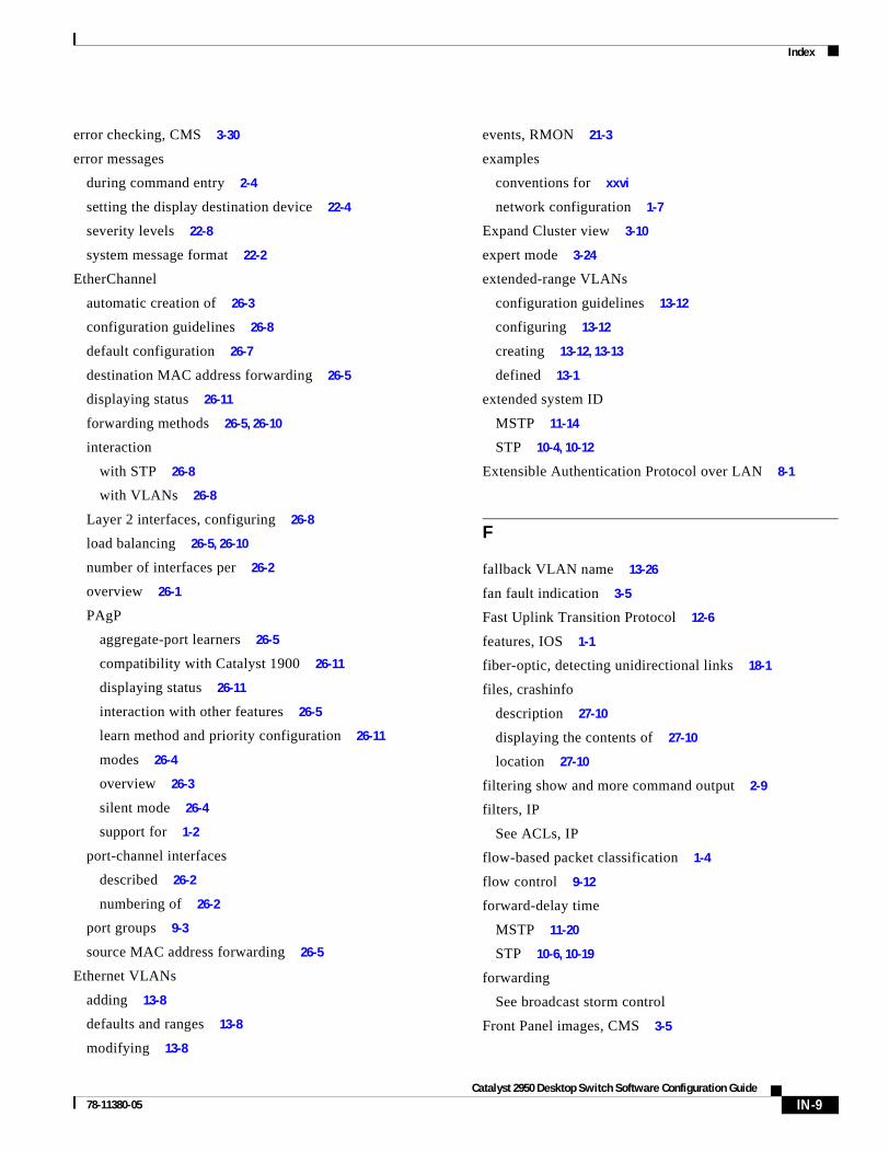
Index
error checking, CMS 3-30
error messages
during command entry 2-4
setting the display destination device 22-4
severity levels 22-8
system message format 22-2
EtherChannel
automatic creation of 26-3
configuration guidelines 26-8
default configuration 26-7
destination MAC address forwarding 26-5
displaying status 26-11
forwarding methods 26-5, 26-10
interaction
with STP 26-8
with VLANs 26-8
Layer 2 interfaces, configuring 26-8
load balancing 26-5, 26-10
number of interfaces per 26-2
overview 26-1
PAgP
aggregate-port learners 26-5
compatibility with Catalyst 1900 26-11
displaying status 26-11
interaction with other features 26-5
learn method and priority configuration 26-11
modes 26-4
overview 26-3
silent mode 26-4
support for 1-2
port-channel interfaces
described 26-2
numbering of 26-2
port groups 9-3
source MAC address forwarding 26-5
Ethernet VLANs
adding 13-8
defaults and ranges 13-8
modifying 13-8
78-11380-05
events, RMON 21-3
examples
conventions for xxvi
network configuration 1-7
Expand Cluster view 3-10
expert mode 3-24
extended-range VLANs
configuration guidelines 13-12
configuring 13-12
creating 13-12, 13-13
defined 13-1
extended system ID
MSTP 11-14
STP 10-4, 10-12
Extensible Authentication Protocol over LAN 8-1
F
fallback VLAN name 13-26
fan fault indication 3-5
Fast Uplink Transition Protocol 12-6
features, IOS 1-1
fiber-optic, detecting unidirectional links 18-1
files, crashinfo
description 27-10
displaying the contents of 27-10
location 27-10
filtering show and more command output 2-9
filters, IP
See ACLs, IP
flow-based packet classification 1-4
flow control 9-12
forward-delay time
MSTP 11-20
STP 10-6, 10-19
forwarding
See broadcast storm control
Front Panel images, CMS 3-5
IN-9Catalyst 2950 Desktop Switch Software Configuration Guide

Index
Front Panel view
cluster tree 3-5
command switch 3-4
described 3-4
pop-up menus 3-20
port icons 3-6
port LEDs 3-7
RPS LED 3-6
switch images 3-5
FTP, accessing MIB files A-2
G
GBICs
1000BASE-LX/LH module 1-9
1000BASE-SX module 1-9
1000BASE-ZX module 1-9
CWDM module 1-16
GigaStack module 1-8
security and identification 27-8
get-bulk-request operation 23-3
get-next-request operation 23-3, 23-4
get-request operation 23-3, 23-4
get-response operation 23-3
Gigabit Interface Converters
See GBICs
GigaStack GBIC
fast transition of redundant link 12-5
See also GBICs
global configuration mode 2-2
graphs, bandwidth 3-7
guide
audience xxiii
ogranization of xxiv
purpose xxiii
guide mode 3-24
IN-10Catalyst 2950 Desktop Switch Software Configuration Guide
H
HC (candidate switch) 6-24
hello time
MSTP 11-19
STP 10-19
help, for the command line 2-3
Help button, CMS 3-27
Help Contents 3-25
history
changing the buffer size 2-5
described 2-5
disabling 2-6
recalling commands 2-5
history table, level and number of syslog messages 22-10
host name list, CMS 3-26
host names
abbreviations appended to 6-24
in clusters 6-17
hosts, limit on dynamic ports 13-31
HP OpenView 1-6
HSRP
automatic cluster recovery 6-16
cluster standby group considerations 6-14
See also clusters, cluster standby group, and standby command switch
HTTP access 3-28, 3-29
Hypertext Transfer Protocol
See HTTP access
I
icons
cluster tree 3-5
colors
cluster tree 3-5
Topology view 3-12
78-11380-05

Index
icons (continued)
editable table cell 3-27
Front Panel view 3-6
multilink 3-21
sorting 3-27
toolbar 3-19
Topology view 3-11
web link 3-27
IE2100
CNS embedded agents
described 5-5
enabling automated configuration 5-6
enabling configuration agent 5-9
enabling event agent 5-8
Configuration Registrar
configID, deviceID, hostname 5-3
configuration service 5-2
described 5-1
event service 5-3
described 1-6
support for 1-2
IEEE 802.1P 15-1
IGMP
joining multicast group 16-2
join messages 16-2
leave processing, enabling 16-9
leaving multicast group 16-4
queries 16-3
IGMP filtering
configuring 16-20
default configuration 16-19
described 16-19
monitoring 16-23
IGMP groups, setting the maximum number 16-22
IGMP profile
applying 16-21
configuration mode 16-20
configuring 16-20
78-11380-05
IGMP snooping
configuring 16-5
default configuration 16-5
definition 16-1
enabling and disabling 16-5
global configuration 16-5
Immediate Leave 16-4
method 16-6
monitoring 16-9
VLAN configuration 16-6
Immediate-Leave, IGMP 16-4
ingress port scheduling 25-8
Intelligence Engine 2100 Series CNS Agents
See IE2100
interaction modes, CMS 3-23
interface
number 9-4
range macros 9-8
interface command 9-4, 9-5
interface configuration mode 2-2
interfaces
configuration guidelines 9-11
configuring 9-5
configuring duplex mode 9-10
configuring speed 9-10
counters, clearing 9-16
described 9-13
descriptive name, adding 9-13
displaying information about 9-14
flow control 9-12
IOS supported 1-5
monitoring 9-14
naming 9-13
physical, identifying 9-4
range of 9-6
restarting 9-17
shutting down 9-17
IN-11Catalyst 2950 Desktop Switch Software Configuration Guide

Index
interfaces (continued)
supported 9-4
types of 9-1
interfaces range macro command 9-8
inventory, cluster 6-25
IOS command-line interface
See CLI
IP
named extended ACL 24-14
named standard ACL 24-14
numbered extended ACL 24-10
numbered standard ACL 24-9
IP ACLs
applying to
management interfaces 24-20
physical interfaces 24-21
extended, creating 24-10
for QoS classification 25-16
implicit deny 24-9, 24-13, 24-15
implicit masks 24-9
management interfaces, applying to 24-20
named 24-13
physical interfaces, applying to 24-21
standard, creating 24-9
undefined 24-19, 24-21
virtual terminal lines, setting on 24-20
IP addresses
candidate or member 6-4, 6-16
cluster access 6-2
command switch 6-3, 6-14, 6-16
discovering 7-59
management VLAN 6-19
redundant clusters 6-14
standby command switch 6-14, 6-16
See also IP information
ip igmp profile command 16-20
IN-12Catalyst 2950 Desktop Switch Software Configuration Guide
IP information
assigned
manually 4-10
through DHCP-based autoconfiguration 4-3
default configuration 4-3
IP multicast routing and IGMP snooping 16-1, 16-5
IP phones
and QoS 15-1
configuring 15-3
trusted boundary for QoS 25-13
IP protocols in ACLs 24-12
J
Java plug-in configuration 3-1, 6-1
join messages, IGMP 16-2
L
Layer 2 frames, classification with CoS 25-2
Layer 2 interfaces, default configuration 9-9
Layer 2 trunks 13-15
Layer 3 packets, classification methods 25-2
Layer 3 parameters of ACEs 24-10
Layer 4 parameters of ACEs 24-10
LDAP 5-2
leave processing, IGMP 16-9
LEDs
port 3-7, 3-8
port modes 3-7
RPS 3-6
legend, CMS icons and labels 3-18
lightweight directory access protocol
See LDAP
line configuration mode 2-2
link icons, Topology view 3-12
78-11380-05

Index
link labels 3-12
link pop-up menu, Topology view 3-21
links, unidirectional 18-1
lists, CMS 3-27
login authentication
with RADIUS 7-22
with TACACS+ 7-13
login banners 7-49
log messages
See system message logging
loop guard
described 12-13
enabling 12-20
support for 1-3
LRE profiles, considerations in switch clusters 6-19
M
MAC addresses
adding secure 7-57
aging time 7-53
and VLAN association 7-53
building the address table 7-52
default configuration 7-53
discovering 7-59
displaying 7-58
dynamic
learning 7-52
removing 7-54
in ACLs 24-18
static
adding 7-57
characteristics of 7-56
removing 7-57
MAC address multicast entries, monitoring 16-10
MAC address-to-VLAN mapping 13-25
MAC extended access lists 24-18
78-11380-05
management options
benefits
clustering 1-6
CMS 1-6
CLI 2-1
CMS 3-1
CNS 5-1
overview 1-5
management VLAN
changing 6-19
considerations in switch clusters 6-9, 6-10, 6-19
discovery through different management VLANs 6-10
discovery through same management VLAN 6-9
IP address 6-19
MANs
CWDM configuration example 1-16
long-distance, high-bandwidth transport configuration example 1-16
mapping tables for QoS
configuring
DSCP 25-24
DSCP-to-CoS 25-26
described 25-5
matching, ACLs 24-7
maximum aging time
MSTP 11-21
STP 10-20
maximum hop count, MSTP 11-21
membership mode, VLAN port 3-8, 13-3
member switch
adding 6-21
automatic discovery 6-5
defined 6-2
managing 6-26
passwords 6-16
recovering from lost connectivity 27-7
requirements 6-4
See also candidate switch, cluster standby group, and standby command switch
IN-13Catalyst 2950 Desktop Switch Software Configuration Guide

Index
menu bar
described 3-14
variations 3-14
messages
system 3-18
to users through banners 7-49
metropolitan-area networks
See MANs
MIBs
accessing files with FTP A-2
location of files A-2
overview 23-1
SNMP interaction with 23-4
supported A-1
mini-point-of-presence
See POP
mirroring traffic for analysis 20-1
mismatches, autonegotiation 27-8
Mode button 3-7
modes
port 3-7
VLAN port membership 3-8
Modify button 3-27
monitoring
access groups 24-23
ACLs 24-22
cables for unidirectional links 18-1
CDP 19-5
IGMP
filters 16-23
snooping 16-9
interfaces 9-14
multicast router interfaces 16-10
MVR 16-18
network traffic for analysis with probe 20-1
port protection 17-12
speed and duplex mode 9-12
IN-14Catalyst 2950 Desktop Switch Software Configuration Guide
monitoring (continued)
traffic flowing among switches 21-1
traffic suppression 17-12
VLANs 13-14
VMPS 13-31
VTP 14-16
MSTP
boundary ports
configuration guidelines 11-12
described 11-10
BPDU filtering
described 12-3
enabling 12-16
BPDU guard
described 12-3
enabling 12-15
CIST, described 11-8
configuration guidelines 11-12
configuring
forward-delay time 11-20
hello time 11-19
link type for rapid convergence 11-22
maximum aging time 11-21
maximum hop count 11-21
MST region 11-13
path cost 11-18
port priority 11-17
root switch 11-14
secondary root switch 11-16
switch priority 11-19
CST
defined 11-8
operations between regions 11-9
default configuration 11-12
default optional feature configuration 12-14
displaying status 11-23
enabling the mode 11-13
78-11380-05

Index
MSTP (continued)
extended system ID
affects on root switch 11-14
affects on secondary root switch 11-16
unexpected behavior 11-14
interface state, blocking to forwarding 12-2
interoperability with 802.1D
described 11-11
restarting migration process 11-22
IST
defined 11-8
master 11-8
operations within a region 11-8
loop guard
described 12-13
enabling 12-20
mapping VLANs to MST instance 11-13
MST region
CIST 11-8
configuring 11-13
described 11-7
hop-count mechanism 11-10
IST 11-8
supported spanning-tree instances 11-7
overview 11-7
Port Fast
described 12-2
enabling 12-14
preventing root switch selection 12-12
root guard
described 12-12
enabling 12-19
root switch
affects of extended system ID 11-14
configuring 11-14
unexpected behavior 11-14
shutdown Port Fast-enabled port 12-3
78-11380-05
multicast groups
and IGMP snooping 16-5
Immediate Leave 16-4
joining 16-2
leaving 16-4
static joins 16-8
multicast router interfaces, monitoring 16-10
multicast router ports, adding 16-7
Multicast VLAN Registration
See MVR
Multilink Decomposer window 3-21
multilink icon 3-21
Multiple Spanning Tree Protocol
See MSTP
MVR
configuring interfaces 16-16
default configuration 16-14
described 16-12
modes 16-16
monitoring 16-18
setting global parameters 16-15
N
named IP ACLs 24-13
NameSpace Mapper
See NSM
native VLAN
configuring 13-20
default 13-20
negotiate trunk mode 3-8
neighboring devices, types of 3-11
IN-15Catalyst 2950 Desktop Switch Software Configuration Guide

Index
network examples
collapsed backbone and switch cluster 1-12
design concepts
cost-effective wiring closet 1-8
high-performance workgroup 1-9
network performance 1-7
network services 1-8
redundant Gigabit backbone 1-9
large campus 1-13
long-distance, high-bandwidth transport configuration 1-16
small to medium-sized network 1-10
network management
CDP 19-1
RMON 21-1
SNMP 23-1
Network Time Protocol
See NTP
no commands 2-4
nontrunking mode 13-16
normal-range VLANs
configuration modes 13-6
defined 13-1
NSM 5-3
NTP
associations
authenticating 7-35
defined 7-33
enabling broadcast messages 7-37
peer 7-36
server 7-36
default configuration 7-35
displaying the configuration 7-41
overview 7-32
restricting access
creating an access group 7-39
disabling NTP services per interface 7-40
IN-16Catalyst 2950 Desktop Switch Software Configuration Guide
NTP (continued)
source IP address, configuring 7-40
stratum 7-32
synchronizing devices 7-36
time
services 7-33
synchronizing 7-32
O
OK button 3-27
online help 3-25
out-of-profile markdown 1-5
overheating indication, switch 3-5
P
PAgP
See EtherChannel
pass-through mode 25-15
passwords
default configuration 7-2
encrypting 7-4
in clusters 6-17, 6-21
in CMS 3-28
overview 7-1
recovery of 27-2
setting
enable 7-3
enable secret 7-4
Telnet 7-5
with usernames 7-6
VTP domain 14-8
path cost
MSTP 11-18
STP 10-16
78-11380-05

Index
PC (passive command switch) 6-13, 6-24
per-VLAN Spanning Tree (PVST) 10-2
per-VLAN Spanning Tree+ (PVST+) 10-8
physical ports 9-2
PIM-DVMRP, as snooping method 16-6
policers
configuring for each matched traffic class 25-21
described 25-3
number of 1-5, 25-7
types of 25-6
policing 1-5, 25-3
policy maps for QoS
characteristics of 25-21
configuring 25-21
described 25-6
displaying 25-28
POP 1-14
Port Aggregation Protocol
See EtherChannel
See PAgP
port-based authentication
authentication server
defined 8-2
RADIUS server 8-2
client, defined 8-2
configuration guidelines 8-7
configuring
manual re-authentication of a client 8-11
quiet period 8-11
RADIUS server 8-10
RADIUS server parameters on the switch 8-9
switch-to-client frame-retransmission number 8-13
switch-to-client retransmission time 8-12
default configuration 8-6
described 8-1
device roles 8-2
displaying statistics 8-14
78-11380-05
port-based authentication (continued)
EAPOL-start frame 8-3
EAP-request/identity frame 8-3
EAP-response/identity frame 8-3
enabling
802.1X authentication 8-8
periodic re-authentication 8-10
encapsulation 8-2
initiation and message exchange 8-3
method lists 8-8
ports
authorization state and dot1x port-control command 8-4
authorized and unauthorized 8-4
resetting to default values 8-14
switch
as proxy 8-2
RADIUS client 8-2
topologies, supported 8-5
port-channel
See EtherChannel
Port Fast
described 12-2
enabling 12-14
mode, spanning tree 13-28
support for 1-3
port icons, Front Panel view 3-6
port LEDs
described 3-8
DUPLX 3-7
port modes 3-7
SPEED 3-7
STAT 3-7
port membership modes, VLAN 3-8, 13-3
port modes
described 3-7
LEDs 3-7
IN-17Catalyst 2950 Desktop Switch Software Configuration Guide

Index
port pop-up menu, Front Panel view 3-20
port priority
MSTP 11-17
STP 10-15
ports
802.1Q trunk 3-8
access 9-2
dynamic access 3-8, 13-3
negotiate trunk 3-8
priority 25-8
protected 17-3
secure 17-4
static-access 3-8, 13-3, 13-11
switch 9-2
trunks 13-15
VLAN assignments 13-11
port scheduling 25-8
port security
aging 17-10
configuring 17-7
default configuration 17-6
described 17-4
displaying 17-12
sticky learning 17-5
violations 17-6
with other features 17-7
port-shutdown response, VMPS 13-25
preferential treatment of traffic
See QoS
preventing unauthorized access 7-1
priority
overriding CoS 15-5
port
described 25-8
trusting CoS 15-6
private VLAN edge ports
see protected ports
IN-18Catalyst 2950 Desktop Switch Software Configuration Guide
privileged EXEC mode 2-2
privilege levels
changing the default for lines 7-8
command switch 6-26
exiting 7-9
logging into 7-9
mapping on member switches 6-26
overview 7-2, 7-7
setting a command with 7-7
protected ports 1-2, 17-3
pruning, VTP
enabling 14-14
enabling on a port 13-20
examples 14-5
overview 14-4
pruning-eligible list
changing 13-20
for VTP pruning 14-4
VLANs 14-14
PSTN 1-13
publications, related xxvii
PVST 13-2
Q
QoS
basic model 25-3
classification
class maps, described 25-6
defined 25-3
in frames and packets 25-3
IP ACLs, described 25-5
MAC ACLs, described 25-5
pass-through mode, described 25-15
policy maps, described 25-6
port default, described 25-4
trust DSCP, described 25-5
78-11380-05

Index
QoS (continued)
classification (continued)
trusted boundary, described 25-13
trusted CoS, described 25-4
types for IP traffic 25-5
types for non-IP traffic 25-4
class maps
configuring 25-20
displaying 25-28
configuration examples
common wiring closet 25-30
intelligent wiring closet 25-30
configuration guidelines 25-10
configuring
class maps 25-20
CoS and WRR 25-27
default port CoS value 25-13
IP extended ACLs 25-18
IP standard ACLs 25-16
MAC ACLs 25-19
policy maps 25-21
port trust states within the domain 25-11
QoS policy 25-16
trusted boundary 25-14
default configuration 25-9
displaying statistics 25-28
egress port scheduling 25-8
ingress port scheduling 25-8
IP phones, detection and trusted settings 25-13
mapping tables
CoS-to-DSCP 25-25
displaying 25-28
DSCP-to-CoS 25-26
types of 25-5
marked-down actions 25-23
marking, described 25-4, 25-6
overview 25-2
pass-through mode 25-15
78-11380-05
QoS (continued)
policers
configuring 25-23
described 25-6
number of 25-7
types of 25-6
policing, described 25-3, 25-6
policy maps
characteristics of 25-21
configuring 25-21
displaying 25-28
queueing, defined 25-4
scheduling, defined 25-4
support for 1-4
trusted bounday 25-13
trust states 25-4
understanding 25-2
quality of service
See QoS
queries, IGMP 16-3
R
RADIUS
attributes
vendor-proprietary 7-29
vendor-specific 7-28
configuring
accounting 7-27
authentication 7-22
authorization 7-26
communication, global 7-20, 7-28
communication, per-server 7-19, 7-20
multiple UDP ports 7-20
default configuration 7-19
defining AAA server groups 7-24
displaying the configuration 7-30
identifying the server 7-19
IN-19Catalyst 2950 Desktop Switch Software Configuration Guide

Index
RADIUS (continued)
in clusters 6-18
limiting the services to the user 7-26
method list, defined 7-19
operation of 7-18
overview 7-17
suggested network environments 7-17
tracking services accessed by user 7-27
range
macro 9-8
of interfaces 9-6
Rapid Spanning Tree Protocol
See RSTP
rcommand command 6-26
reconfirmation interval, VMPS, changing 13-30
recovery procedures 27-1
redundancy
EtherChannel 26-2
STP
backbone 10-8
multidrop backbone 12-5
path cost 13-23
port priority 13-21
redundant clusters
See cluster standby group
redundant links and UplinkFast 12-17
redundant power system
See RPS
Refresh button 3-27
Remote Authentication Dial-In User Service
See RADIUS
remote monitoring
see RMON
Remote Network Monitoring
See RMON
removing secure addresses 7-57
resetting a UDLD-shutdown interface 18-5
IN-20Catalyst 2950 Desktop Switch Software Configuration Guide
restricting access
NTP services 7-38
overview 7-1
passwords and privilege levels 7-2
RADIUS 7-17
TACACS+ 7-9
retry count, VMPS, changing 13-30
RFC
1112, IP multicast and IGMP 16-2
1157, SNMPv1 23-2
1305, NTP 7-32
1757, RMON 21-2
1901, SNMPv2C 23-2
1902 to 1907, SNMPv2 23-2
2236, IP multicast and IGMP 16-2
2273-2275, SNMPv3 23-2
RMON
default configuration 21-3
displaying status 21-6
enabling alarms and events 21-3
groups supported 21-2
overview 21-1
statistics
collecting group Ethernet 21-5
collecting group history 21-5
root guard
described 12-12
enabling 12-19
support for 1-3
root switch
MSTP 11-14
STP 10-12
RPS LED 3-6
RSPAN
configuration guidelines 20-10
default configuration 20-6
destination ports 20-4
78-11380-05

Index
RSPAN (continued)
displaying status 20-14
interaction with other features 20-5
monitored ports 20-4
monitoring ports 20-4
overview 1-5, 20-1
received traffic 20-3
reflector port 20-4
session limits 20-6
sessions
creating 20-11
defined 20-3
removing source (monitored) ports 20-13
specifying monitored ports 20-11
source ports 20-4
transmitted traffic 20-3
RSTP
active topology, determining 11-2
BPDU
format 11-5
processing 11-6
configuration guidelines 11-12
designated port, defined 11-2
designated switch, defined 11-2
interoperability with 802.1D
described 11-11
restarting migration process 11-22
topology changes 11-6
overview 11-2
port roles
described 11-2
synchronized 11-4
proposal-agreement handshake process 11-3
rapid convergence
edge ports and Port Fast 11-3
point-to-point links 11-3, 11-22
root ports 11-3
root port, defined 11-2
See also MSTP
78-11380-05
running configuration, saving 4-10
S
SC (standby command switch) 6-13, 6-24
secure addresses
adding 7-57
described 7-57
secure ports, configuring 17-4
security, port 17-4
sequence numbers in log messages 22-8
server mode, VTP 14-3
servers, BOOTP 1-2
service-provider network, MSTP and RSTP 11-1
set-request operation 23-4
setup program, failed command switch replacement 27-5, 27-6
severity levels, defining in system messages 22-8
show and more command output, filtering 2-9
show cdp traffic command 19-5
show cluster members command 6-26
show configuration command 9-13
show interfaces command 9-12, 9-13
show running-config command
displaying ACLs 24-19, 24-20, 24-21
interface description in 9-13
shutdown command on interfaces 9-17
Simple Network Management Protocol
See SNMP
SNAP 19-1
SNMP
accessing MIB variables with 23-4
agent
described 23-3
disabling 23-7
community strings
configuring 23-7
for cluster switches 23-4
overview 23-4
IN-21Catalyst 2950 Desktop Switch Software Configuration Guide

Index
SNMP (continued)
configuration examples 23-14
default configuration 23-6
groups 23-8
in clusters 6-17
informs
and trap keyword 23-10
described 23-5
differences from traps 23-5
enabling 23-12
limiting access by TFTP servers 23-13
limiting system log messages to NMS 22-10
manager functions 23-3
managing clusters with 6-27
MIBs
location of A-2
supported A-1
notifications 23-5
overview 23-1, 23-4
status, displaying 23-15
system contact and location 23-13
trap manager, configuring 23-11
traps
described 23-3, 23-5
differences from informs 23-5
enabling 23-10
enabling MAC address notification 7-54
overview 23-1, 23-4
types of 23-10
users 23-8
versions supported 23-2
snooping, IGMP 16-1
software, VLAN considerations 14-8
software images
recovery procedures 27-2
See also downloading and uploading
source addresses, in ACLs 24-12
IN-22Catalyst 2950 Desktop Switch Software Configuration Guide
SPAN
configuration guidelines 20-7
default configuration 20-6
destination ports 20-4
displaying status 20-14
interaction with other features 20-5
monitored ports 20-4
monitoring ports 20-4
overview 1-5, 20-1
received traffic 20-3
session limits 20-6
sessions
creating 20-7
defined 20-3
removing destination (monitoring) ports 20-9
removing source (monitored) ports 20-9
specifying monitored ports 20-7
source ports 20-4
transmitted traffic 20-3
spanning tree and native VLANs 13-17
Spanning Tree Protocol
See STP
speed, configuring on interfaces 9-10
Stack Membership Discovery Protocol 12-6
Standby Command Configuration window 6-24
standby command switch
configuring 6-23
considerations 6-14
defined 6-2
priority 6-13
requirements 6-3
virtual IP address 6-14
See also cluster standby group and HSRP
standby group, cluster
See cluster standby group and HSRP
static access mode 3-8
78-11380-05

Index
static access ports
assigning to VLAN 13-11
defined 9-2, 13-3
static addresses
See addresses
static VLAN membership 13-2
statistics
802.1X 8-14
CDP 19-5
interface 9-14
QoS ingress and egress 25-28
RMON group Ethernet 21-5
RMON group history 21-5
SNMP input and output 23-15
VTP 14-16
status bar
change notification 3-30
error notification 3-30
sticky learning 17-5
storm control
described 17-1
displaying 17-12
STP
accelerating root port selection 12-4
BackboneFast
described 12-10
enabling 12-19
BPDU filtering
described 12-3
enabling 12-16
BPDU guard
described 12-3
enabling 12-15
BPDU message exchange 10-2
configuration guidelines 10-10
78-11380-05
STP (continued)
configuring
forward-delay time 10-19
hello time 10-19
in cascaded stack 10-20
maximum aging time 10-20
path cost 10-16
port priority 10-15, 11-17
root switch 10-12
secondary root switch 10-14
switch priority 10-18
cross-stack UplinkFast
described 12-5
enabling 12-18
default configuration 10-10
default optional feature configuration 12-14
designated port, defined 10-3
designated switch, defined 10-3
detecting indirect link failures 12-10
disabling 10-12
displaying status 10-21
extended system ID
affects on root switch 10-12
affects on the secondary root switch 10-14
overview 10-4
unexpected behavior 10-13
features supported 1-3
inferior BPDU 10-3
interface state, blocking to forwarding 12-2
interface states
blocking 10-7
disabled 10-8
forwarding 10-6, 10-7
learning 10-7
listening 10-7
overview 10-5
limitations with 802.1Q trunks 10-8
IN-23Catalyst 2950 Desktop Switch Software Configuration Guide

Index
STP (continued)
load sharing
overview 13-21
using path costs 13-23
using port priorities 13-21
loop guard
described 12-13
enabling 12-20
multicast addresses, affect of 10-8
overview 10-2
path costs 13-23, 13-24
Port Fast
described 12-2
enabling 12-14
port priorities 13-22
preventing root switch selection 12-12
redundant connectivity 10-8
root guard
described 12-12
enabling 12-19
root port, defined 10-3
root switch
affects of extended system ID 10-4, 10-12
configuring 10-12
election 10-3
unexpected behavior 10-13
settings in a cascaded stack 10-20
shutdown Port Fast-enabled port 12-3
superior BPDU 10-3
supported number of spanning-tree instances 10-2
timers, described 10-4
UplinkFast
described 12-4
enabling 12-17
stratum, NTP 7-32
summer time 7-44
SunNet Manager 1-6
IN-24Catalyst 2950 Desktop Switch Software Configuration Guide
switch clustering technology 6-1
See clusters, switch
switched ports 9-2
Switch Manager 3-2, 3-31
See also Device Manager
switchport protected command 17-3
switch priority
MSTP 11-19
STP 10-18
syslog
See system message logging
system clock
configuring
daylight saving time 7-44
manually 7-42
summer time 7-44
time zones 7-43
displaying the time and date 7-42
overview 7-32
See also NTP
system message logging
default configuration 22-3
defining error message severity levels 22-8
disabling 22-4
displaying the configuration 22-12
enabling 22-4
facility keywords, described 22-12
level keywords, described 22-9
limiting messages 22-10
message format 22-2
overview 22-1
sequence numbers, enabling and disabling 22-8
setting the display destination device 22-4
synchronizing log messages 22-6
timestamps, enabling and disabling 22-7
78-11380-05

Index
system message logging (continued)
UNIX syslog servers
configuring the daemon 22-11
configuring the logging facility 22-11
facilities supported 22-12
system messages on CMS 3-18
system name
default configuration 7-46
default setting 7-46
manual configuration 7-46
See also DNS
system prompt
default setting 7-46
manual configuration 7-47
T
tables, CMS 3-27
tabs, CMS 3-27
TACACS+
accounting, defined 7-10
authentication, defined 7-10
authorization, defined 7-10
configuring
accounting 7-16
authentication key 7-12
authorization 7-15
login authentication 7-13
default configuration 7-12
displaying the configuration 7-16
identifying the server 7-12
in clusters 6-18
limiting the services to the user 7-15
operation of 7-11
overview 7-9
tracking services accessed by user 7-16
78-11380-05
Telnet
accessing management interfaces 2-9
accessing the CLI 1-6
from a browser 2-10
setting a password 7-5
Terminal Access Controller Access Control System Plus
See TACACS+
terminal lines, setting a password 7-5
TFTP
configuration files in base directory 4-6
configuring for autoconfiguration 4-5
limiting access by servers 23-13
time
See NTP and system clock
time-range command 24-15
time ranges in ACLs 24-15
timestamps in log messages 22-7
time zones 7-43
Token Ring VLANs
support for 13-5
VTP support 14-4
toolbar 3-19
tool tips 3-25
Topology view
Collapse Cluster view 3-10
described 3-2, 3-9
device icons 3-11, 3-12
device labels 3-12
display options 3-13
Expand Cluster view 3-10
icons 3-11
link icons 3-12
link labels 3-12
multilink icon 3-21
neighboring devices 3-11
pop-up menus 3-21
IN-25Catalyst 2950 Desktop Switch Software Configuration Guide

Index
TOS 1-4
traffic
fragmented 24-3
unfragmented 24-3
traffic policing 1-5
transparent mode, VTP 14-3, 14-12
trap-door mechanism 4-2
traps
configuring MAC address notification 7-54
configuring managers 23-10
defined 23-3
enabling 7-54, 23-10
notification types 23-10
overview 23-1, 23-4
troubleshooting
detecting unidirectional links 18-1
displaying crash information 27-10
GBIC security and identification 27-8
with CiscoWorks 23-4
with debug commands 27-8
with system message logging 22-1
trunk ports
configuring 13-18
defined 9-3
trunks
allowed-VLAN list 13-19
load sharing
setting STP path costs 13-23
using STP port priorities 13-21, 13-22
native VLAN for untagged traffic 13-20
parallel 13-23
pruning-eligible list 13-20
to non-DTP device 13-15
understanding 13-15
trusted boundary 25-13
twisted-pair Ethernet, detecting unidirectional links 18-1
type-of-service
See TOS
IN-26Catalyst 2950 Desktop Switch Software Configuration Guide
U
UDLD
default configuration 18-3
echoing detection mechanism 18-2
enabling
globally 18-4
per interface 18-4
link-detection mechanism 18-1
neighbor database 18-2
overview 18-1
resetting an interface 18-5
status, displaying 18-6
unauthorized ports with 802.1X 8-4
UniDirectional Link Detection protocol
See UDLD
UNIX syslog servers
daemon configuration 22-11
facilities supported 22-12
message logging configuration 22-11
unrecognized Type-Length-Value (TLV) support 14-4
upgrading software, VLAN considerations 14-8
UplinkFast
described 12-4
enabling 12-17
support for 1-3
user EXEC mode 2-2
username-based authentication 7-6
V
verifying changes in CMS 3-30
version-dependent transparent mode 14-4
virtual IP address
cluster standby group 6-14, 6-24
command switch 6-14, 6-24
See also IP addresses
vlan.dat file 13-4
78-11380-05

Index
VLAN configuration
at bootup 13-7
saving 13-7
VLAN configuration mode 2-2, 13-6
VLAN database
and startup configuration file 13-7
and VTP 14-1
VLAN configuration saved in 13-7
VLANs saved in 13-4
vlan database command 13-6
vlan global configuration command 13-6
VLAN ID, discovering 7-59
VLAN management domain 14-2
VLAN Management Policy Server
See VMPS
VLAN membership
confirming 13-30
modes 3-8, 13-3
VLAN Query Protocol
See VQP
VLANs
adding 13-8
adding to VLAN database 13-8
aging dynamic addresses 10-9
allowed on trunk 13-19
and spanning-tree instances 13-2, 13-6, 13-13
configuration guidelines, normal-range VLANs 13-5
configuration options 13-6
configuring 13-1
configuring IDs 1006 to 4094 13-12
creating in config-vlan mode 13-9
creating in VLAN configuration mode 13-9
default configuration 13-8
deleting 13-10
described 9-1, 13-1
displaying 13-14
extended-range 13-1, 13-12
illustrated 13-2
78-11380-05
VLANs (continued)
modifying 13-8
native, configuring 13-20
normal-range 13-1, 13-4
parameters 13-4
port membership modes 3-8, 13-3
static-access ports 13-11
STP and 802.1Q trunks 10-8
supported 13-2
Token Ring 13-5
VTP modes 14-3
VLAN Trunking Protocol
See VTP
VLAN trunks 13-15
VMPS
administering 13-31
configuration example 13-32
configuration guidelines 13-28
default configuration 13-27
description 13-24
dynamic port membership
described 13-25
reconfirming 13-30
troubleshooting 13-31
entering server address 13-28
mapping MAC addresses to VLANs 13-25
monitoring 13-31
reconfirmation interval, changing 13-30
reconfirming membership 13-30
retry count, changing 13-30
voice VLAN
Cisco 7960 phone, port connections 15-1
configuration guidelines 15-3
configuring IP phones for data traffic
override CoS of incoming frame 15-5
trust CoS priority of incoming frame 15-6
IN-27Catalyst 2950 Desktop Switch Software Configuration Guide

Index
voice VLAN (continued)
configuring ports for voice traffic in
802.1P priority tagged frames 15-4
802.1Q frames 15-4
connecting to an IP phone 15-3
default configuration 15-2
described 15-1
displaying 15-6
VQP 13-24
VTP
adding a client to a domain 14-15
advertisements 13-17, 14-3
and extended-range VLANs 14-1
and normal-range VLANs 14-1
client mode, configuring 14-11
configuration
global configuration mode 14-7
guidelines 14-8
privileged EXEC mode 14-7
requirements 14-9
saving 14-7
VLAN configuration mode 14-7
configuration mode options 14-7
configuration requirements 14-9
configuration revision number
guideline 14-15
resetting 14-15
configuring
client mode 14-11
server mode 14-9
transparent mode 14-12
consistency checks 14-4
default configuration 14-6
described 14-1
disabling 14-12
domain names 14-8
domains 14-2
IN-28Catalyst 2950 Desktop Switch Software Configuration Guide
VTP (continued)
modes
client 14-3, 14-11
server 14-3, 14-9
transitions 14-3
transparent 14-3, 14-12
monitoring 14-16
passwords 14-8
pruning
disabling 14-14
enabling 14-14
examples 14-5
overview 14-4
pruning-eligible list, changing 13-20
server mode, configuring 14-9
statistics 14-16
Token Ring support 14-4
transparent mode, configuring 14-12
using 14-1
version, guidelines 14-9
version 1 14-4
version 2
configuration guidelines 14-9
disabling 14-13
enabling 14-13
overview 14-4
W
warnings xxvi
web-based management software
See CMS
Weighted Round Robin
See WRR
window components, CMS 3-26
wizards 3-24
78-11380-05

Index
WRR
configuring 25-27
defining 25-8
description 25-8
X
XMODEM protocol 27-2
78-11380-05
IN-29Catalyst 2950 Desktop Switch Software Configuration Guide
Index
IN-30Catalyst 2950 Desktop Switch Software Configuration Guide
78-11380-05