Embed Size (px)
Citation preview

NASA Reference Publication 1317 January 1994
Catalog of Apollo Experiment Operations
Thomas A. Sullivan


NASA Reference Publication 1317 January 1994
Catalog of Apollo Experiment Operations
Thomas A. Sullivan NASA - Johnson Space Center Houston, Texas
National Aeronautic and Space Administration


iii
Preface
The accomplishments of the Apollo missions to the Moon unfolded on the TV screens of America almost as a given. While there were certainly moments when things did not go as planned, for the most part it looked easy. Walking and driving on the lunar surface, laying out experiment packages, and collecting samples all seemed as natural as the many science fiction stories we had been reading for years.
Of course, it wasn't that easy. Years of planning, training, rethinking, and improvement had gone into those operations. Carrying out useful work from inside a pressure suit required a great deal of compromise on the part of experiment designers and mission planners. Even then, many tasks which were accomplished turned out to be extremely difficult. The lunar environment, especially its dust, low gravity, and vacuum, made it difficult to perform many operations. The need for a pressure suit lowered the productivity of an individual, making it a constant struggle to even merely grip something.
Someday we will be going back to the Moon and even onward to Mars. Many of the things we want to do there will be similar to those we have already done. True, the instruments will be better and may be used for different purposes, but the tasks required of an astronaut and the design problems faced by the engineers will largely be the same. I hope to capture, with this document, some of the knowledge from the Apollo era to make the jobs of those future designers and operators of lunar experiments somewhat more productive.
The original motivation for this database came from the Astronaut Office, Science Support Group, which wanted to document the experience of the astronaut/experiment interface from the operations perspective. Beyond that, I hope to retain some of the "lessons learned" from the Apollo experience so that future astronauts, principle investigators, design engineers, and trainers will not need to make many of the same mistakes in operation and design of instruments and tools created for use by a crew in an extravehicular mobility unit with time constraints, on a planet with low gravity.
In addition to the usual meaning of the term "experiment," I have included some pieces of equipment and hardware, such as the lunar rover and some of the tools the crew had available. Also included in this database are a few experiments performed in the command module during translunar and trans-Earth coasts that were precursors to some Skylab experiments. While we have come a long way since then, some of the problems we still have in microgravity today were first seen in the Apollo command module.
The progress made in the late '60s and early '70s was not as well documented as one might have hoped. We were operating at such a rapid pace that no one had the time to write it all down. The present effort was started by reviewing relevant documents, such as Apollo mission reports, preliminary science reports, technical crew debriefings, lunar surface operations plans, and various lunar experiment documents, and then collecting general and operation-specific information by experiment. After this, the crews who actually dealt with these experiments on the Moon were consulted for their input with 20+ years of hindsight. The anecdotes some of them shared concerning the deployment and operation of these units is probably the most valuable information in this document.
Thomas A. Sullivan Solar System Exploration Division NASA - Lyndon B. Johnson Space Center

iv
Acknowledgments This document was started at the request of Dr. Bonnie Dunbar, without whose foresight I would not have had the opportunity to uncover so much of our past. It would not have been possible without the help of Joey Kuhlman and Janet Kovacevich in the JSC History Office. They were able to find information in the archives that I did not know existed. Likewise, Annie Platoff provided access to documents which had long since been kept on anyone's shelf. Eric Jones was also very helpful in providing anecdotes related to him by the crews. Of course, the twelve astronauts that did the actual work on the Moon and allowed us to increase our knowledge of our solar system are owed a great debt, as are the teams of scientists and engineers who helped make it happen. I also need to thank John Young, Thornton Page, and Jack Sevier for their help and time discussing those experiments on which they worked. Mike Foale's review of what I had hoped was the final draft helped me to realize that more comparison of planned and actual timelines would be instructive to future EVA planners. Finally, my thanks go to several people in the Solar System Exploration Division who talked with me in the hallways and gave me tips about who to talk to and what really happened back when I was just a kid in high school.

v
Table of Contents
Section Page
Preface .................................................................................................................................. iii Acknowledgments ............................................................................................................................. iv Contents .................................................................................................................................. v Acronyms .................................................................................................................................. viii Introduction .................................................................................................................................. x
Part I Lunar Surface Experiment Operations During Apollo Extravehicular Activities (EVAs)
Active Seismic Experiment ............................................................................................................... 1 Apollo Lunar Surface Experiments Package (ALSEP) - General Information ................................. 5 Cameras - General Information ......................................................................................................... 11 Charged Particle Lunar Environment Experiment ............................................................................ 14 Cold Cathode Gauge Experiment ...................................................................................................... 17 Cosmic Ray Detector Experiment/Lunar Surface Cosmic Ray Experiment ..................................... 20 Dust Detector Experiment ................................................................................................................. 25 Early Apollo Surface Experiments Package (EASEP) - General Information .................................. 28 Far Ultraviolet (UV) Camera/Spectrograph ...................................................................................... 31 Gravimeter, Lunar Surface ................................................................................................................ 35 Gravimeter, Traverse ......................................................................................................................... 38 Heat Flow Experiment ....................................................................................................................... 41 Laser Ranging Retroreflector ............................................................................................................ 45 Lunar Atmosphere Composition Experiment .................................................................................... 48 Lunar Ejecta and Meteorites Experiment .......................................................................................... 51 Lunar Geology Experiment - General Information ........................................................................... 54 Lunar Geology Experiment - Tools ................................................................................................... 60 Lunar Neutron Probe Experiment ..................................................................................................... 64 Lunar Rover Vehicle - General Information ..................................................................................... 67 Lunar Seismic Profiling Experiment ................................................................................................. 72 Magnetometer, Lunar Surface ........................................................................................................... 75 Magnetometer, Portable .................................................................................................................... 78 Miscellaneous Tools and Equipment ................................................................................................ 81 Passive Seismic Experiment (Package) ............................................................................................. 87 Soil Mechanics Experiment .............................................................................................................. 91 Solar Wind Composition Experiment ............................................................................................... 95 Solar Wind Spectrometer Experiment ............................................................................................... 99 Suprathermal Ion Detector Experiment ............................................................................................. 102 Surface Electrical Properties Experiment ......................................................................................... 106 Surveyor 3 Retrieval .......................................................................................................................... 110 Thermal Degradation Sample............................................................................................................. 113

vi
Table of Contents (continued)
Section Page
Part II Experiment Operations at Microgravity During Trans-Lunar and Trans-Earth Coast........................................................................................................ 116
Composite Casting Demonstration, Apollo 14 .................................................................................. 118 Electrophoresis Demonstration, Apollo 14 ....................................................................................... 120 Electrophoresis Demonstration, Apollo 16 ....................................................................................... 122 Heat Flow and Convection Demonstration, Apollo 14 ..................................................................... 125 Heat Flow and Convection Demonstration, Apollo 17 ..................................................................... 127 Light Flashes Experiment .................................................................................................................. 130 Liquid Transfer Demonstration, Apollo 14 ....................................................................................... 133 Part III Summary of Lessons Learned and Guidelines for Future Experiments ........ 135
Appendix A - Apollo Experiments and Missions ............................................................................. A-1 Appendix B-Bibliography .................................................................................................................. B-1

vii
Table of Contents (continued)
Figures Page
1 Mortar package assembly .......................................................................................................... 4 2 ALSEP central station from Apollo 14 ..................................................................................... 10 3 CPLEE deployed at Apollo 14 ALSEP site .............................................................................. 16 4 CCIG, SIDE at Apollo 14 ALSEP site ...................................................................................... 19 5 CRD ........................................................................................................................................... 23 6 LSCRE ...................................................................................................................................... 24 7 DTREM schematic .................................................................................................................... 27 8 EASEP, containing PSEP and LRRR ....................................................................................... 30 9 Far UV camera .......................................................................................................................... 34 10 LSG deployed at Apollo 17 ALSEP site ................................................................................... 37 11 TGE experiment ........................................................................................................................ 40 12 HFE on Apollo 15 ..................................................................................................................... 44 13 LR3 on Apollo 14 ...................................................................................................................... 47 14 LACE at Apollo 17 ALSEP site ................................................................................................ 50 15 LEAM at Apollo 17 ALSEP site ............................................................................................... 53 16 Apollo 12 astronaut using tongs ................................................................................................ 59 17 Astronaut using rake ................................................................................................................. 62 18 Astronaut emplacing core tube into ground .............................................................................. 63 19 Lunar neutron probe .................................................................................................................. 66 20 LRV on Apollo 16 ..................................................................................................................... 71 21 Explosive package used for the LSPE ...................................................................................... 74 22 LSM deployed at Apollo 16 ALSEP site .................................................................................. 77 23 LPM on Apollo 16 .................................................................................................................... 80 24 MET .......................................................................................................................................... 85 25 Erectable antenna on Apollo 14 ................................................................................................ 85 26 RTG deployed for Apollo 14 ALSEP ....................................................................................... 86 27 Fuel cask on Apollo 12 ............................................................................................................. 86 28 PSEP deployed on Apollo 11 .................................................................................................... 90 29 PSE, with shroud deployed ....................................................................................................... 90 30 Trench dug for soil mechanics investigation ............................................................................ 93 31 SWC foil deployed on Apollo 11 .............................................................................................. 96 32 SWC foil on Apollo 16 ............................................................................................................. 97 33 SWS deployed on Apollo 15 ..................................................................................................... 100 34 SIDE deployed on Apollo 14 .................................................................................................... 104 35 SIDE deployed at Apollo 15 ALSEP site .................................................................................. 104 36 SEP transmitter deployed near Apollo 17 landing site ............................................................. 108 37 SEP receiving antenna on Apollo 17 LRV ............................................................................... 108 38 Astronaut Alan Bean and two U.S. spacecraft on surface of Moon ......................................... 111 39 Panels I to 6 of TDS 1002 ......................................................................................................... 114 40 Electrophoresis demonstration on Apollo 16 ............................................................................ 122 41 Electrophoresis demonstration - left side view ......................................................................... 123 42 Panel face of Apollo 17 heat flow and convection apparatus ................................................... 128 43 Interior view of ALFMED device ............................................................................................. 131 44 ALFMED device worn during investigation ............................................................................. 131

viii
Acronyms A Apollo (as in A- 14) ALCC Apollo Lunar Closeup (Stereoscopic) Camera ALFMED Apollo Light Flashes Moving Emulsion Detector ALHT Apollo Lunar Hand Tools ALSD Apollo Lunar Surface Drill ALSEP Apollo Lunar Surface Experiment Package ALSRC Apollo lunar-sample return containers ASE Active Seismic Experiment ASP Apollo Simple Penetrometer CCIG Cold Cathode Ion Gauge CCG(E) Cold Cathode Gauge (Experiment) CDR Commander CM Command Module CMP Command Module Pilot CPLEE Charged Particle Lunar Environment Experiment CRD(E) Cosmic Ray Detector (Experiment) CSM Command/Service Module DAC Data acquisition camera DRT Dome Removal Tool DSEA Data storage electronics assembly DTREM Dust, Thermal, & Radiation Engineering Measurements EASEP Early Apollo Scientific Experiment Package EAU Electromagnetic Interference EMU Extravehicular Mobility Unit EOS Electrophoresis Operations in Space ETB Equipment Transfer Bag eV Electron Volts EVA Extravehicular Activity FOV Field of View FIT Fuel Transfer Tool HFC Heat Flow and Convection HFE Heat Flow Experiment IVA Intravehicular Activity JPL Jet Propulsion Lab JSC Johnson Space Center LACE Lunar Atmosphere Composition Experiment LCRU Lunar Communications Relay Unit LDD Lunar Dust Detector LDEF Long-Duration Exposure Facility LEAM Lunar Ejecta and Meteorites LEC Lunar Equipment Conveyor I-M Lunar Module

ix
Acronyms (continued)
LMP Lunar Module Pilot LMS Lunar Mass Spectrometer LNPE Lunar Neutron Probe Experiment LPM Lunar Portable Magnetometer LRRR,LR3 Laser Ranging Retroreflector LRV Lunar Rover Vehicle LSCRE Lunar Surface Cosmic Ray Experiment LSG Lunar Surface Gravimeter LSM Lunar Surface Magnetorneter LSPE Lunar Seismic Profiling Experiment LSUC Lunar Surface Ultraviolet Camera LTD Liquid Transfer Demonstration MCC Mission Control Center MESA Modularized Equipment Stowage Assembly MET Modularized Equipment Transporter MPA Mortar Package Assembly MSC Manned Spacecraft Center PI Principal Investigator PLSS Portable Life Support System PSE(P) Passive Seismic Experiment (Package) RTG Radioisotope Thermal Generator SEB Scientific Equipment Bay SEP Surface Electrical Properties Experiment SIDE Suprathermal Ion Detector Experiment SIVB Saturn launch vehicle 3rd stage SNAP-27 System for Nuclear Auxiliary Power SM Service Module SRC Sample Return Containers SRP Self-Recording Penetrometer SWC Solar Wind Composition SWS Solar Wind Spectrometer TDS Thermal Degradation Samples TGE Traverse Gravimeter Experiment UHT Universal Handling Tool UV Ultraviolet UVC Ultraviolet Camera

x
Introduction
This catalog is organized by discrete experiments and selected pieces of equipment used or emplaced by an astronaut during the Apollo program. Part I consists of experiments performed on the lunar surface. Each of the Apollo Lunar Surface Experiment Package (ALSEP) experiments is described individually in addition to being addressed in a general ALSEP section. The many other experiments performed on the surface are likewise listed under their own title. Certain tools or pieces of equipment which were critical to experiment operations are also listed, since they were key to the successful performance of the task.
There are also seven experiments which were performed at microgravity during the trans-lunar or trans-Earth coasts. These are collected in Part 111.
Within each experiment, general information about the principal investigator (PI) and other contacts, experiment mass and dimensions, manufacturer, and the mission(s) it flew on is provided. The Apollo experiment number is listed, an attempt to classify it into a discipline of study is made, and a description of the hardware and purpose is provided. After this, a general set of questions that are operational in nature is applied to the experiment so that the interaction of the crew with the experiment or hardware can be understood. Not all questions make sense for each experiment, but a standard battery of questions was applied to all with the idea that it might trigger the recollection of some unique aspect of that operation. Many experiments flew on more than one mission, and improvements were made for the follow-on flights based on the difficulties experienced. A cross reference to other similar experiments from Apollo or other efforts is also provided. Some disciplines which continue to be studied on the Space Shuttle today are listed as a discipline code. This code is relevant to an on-line database of shuttle experiments prepared by the Flight Crew Operations Directorate at JSC.
Part HI attempts to summarize some of the general problems encountered on the lunar surface and provides guidelines for the design of future experiments to enable easier operation. Parts I and 11 are intended to also be incorporated into an electronic database that can be searched using many different query types. This remains a task for the near future.

Part 1: Lunar Surface Experiment Operations During Apollo EVAs
Active Seismic Experiment
Apollo Lunar Surface Experiments Package (ALSEP) - General
Cameras - General Information
Charged Particle Lunar Environment Experiment
Cold Cathode Gauge Experiment
Cosmic Ray Detector Experiment/Lunar Surface Cosmic Ray Experiment
Lunar Dust Detector Experiment
Early Apollo Surface Experiments Package (EASEP) - General
Far UV Camera/Spectrograph
Gravimeter, Lunar Surface
Gravirneter, Traverse
Heat Flow Experiment
Laser Ranging Retroreflector
Lunar Atmosphere Composition Experiment
Lunar Ejecta and Meteorites Experiment
Lunar Geology Experiment - General
Lunar Geology Experiment - Tools
Lunar Neutron Probe Experiment
Lunar Rover Vehicle - General Information
Lunar Seismic Profiling Experiment
Magnetometer, Lunar Surface
Magnetometer, Portable
Miscellaneous Tools and Equipment
Passive Seismic Experiment (Package)
Soil Mechanics Experiment
Solar Wind Composition Experiment
Solar Wind Spectrometer Experiment
Suprathermal Ion Detector Experiment
Surface Electrical Properties Experiment
Surveyor 3 Retrieval
Thermal Degradation Sample


1
Experiment Operations During Apollo EVAs Acronym: ASE
PI/Engineer: Robert L. Kovack/ Stanford University
Apollo Flight Nos.: 14, 16
Weight: 11.2 kg
Manufacturer: Bendix (grenade launcher made by Space Ordinance Systems, Inc.)
Experiment: Active Seismic Experiment
Other Contacts: Tom Landers/Stanford Joel S. Watkins/University of NC
Discipline: Lunar Seismology
Dimensions: See ALSEP Flight System Familiarization Manual, p. 2-152 for data on all the ASE subsystems
Apollo Experiment No.: S 033
Description/Purpose—A string of three geophones was emplaced by Apollo 14 (A-14) and A-16. This allowed profiling of the internal structure of the Moon to a depth of -460 m. Two seismic sources were included: an astronaut-activated thumper device containing 21 small explosive initiators, and a rocket grenade launcher that was capable of launching four grenades at known times and distances (150, 300, 900, and 1500 m) from the seismometer. High frequency natural seismic activity was monitored with the geophones. Electronics for the experiment were within the Apollo Lunar Surface Experiments Package (ALSEP) central station.
The astronaut-activated thumper was a short staff used to detonate small explosive charges—single bridgewire Apollo standard initiators. Twenty-one initiators were mounted perpendicular to the base plate at the lower end of the staff. This flat base plate was driven down against the surface to provide a known energy pulse. A pressure switch in the plate detected the instant of initiation. An arm/fire switch and an initiator/selector switch were located at the upper end of the staff. A cable connected the thumper to the central station to transmit real-time event data. The thumper also stored the three geophones and connecting cable until deployment.
The three identical geophones were miniature moving coil-magnet seismometers. They were anchored into the surface by short spikes as they were unreeled from the thumper/geophone assembly. They were emplaced 46 m apart and were sensitive to signals with frequencies in the range of 3 to 250 Hz.
The mortar package assembly (MPA) comprised a mortar box, a grenade launch tube assembly, and interconnecting cables. A two-axis inclinometer provided pitch and roll angle data. Many safeguards existed on arming, launching, and detonating the grenades, all of which were done from Earth after crew departure. The A-16 MPA was modified to have a more stable base than the one on A-14.
Unloading from the lunar module (LM)—As part of the ALSEP.
Transporting by foot or modularized equipment transporter (MET)—As part of the ALSEP.
Loading/unloading tools/experiments on lunar rover vehicle (LRV)—NA
Site selection—As part of the ALSEP.
Deploying experiment—The geophones deployed very easily on A-14. They went into the soft surface readily and were then stepped on to implant them. However, the loose soil gave little resistance to hold them in place, and in moving the cable Edgar Mitchell pulled the second geophone out of the soil and it had to be replaced. While deploying the ASE electronics package on A-16, the cable became taut and pulled on the central station. The crewman had to go back and adjust the central station. Before unreeling the geophone cable, it was staked in place (with the aid of an extension handle) through a loop in the cable so that the lunar module pilot (LMP) would not drag the central station behind him while laying out the geophone line. The foot pads on the mortar pack rotated out of the proper position, and the package had to be picked up and the pads rotated to a position in which they would rest properly
2
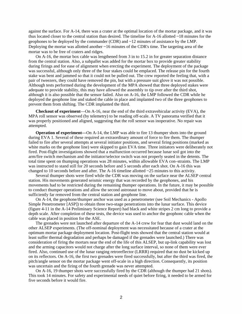
against the surface. For A-14, there was a crater at the optimal location of the mortar package, and it was thus located closer to the central station than desired. The timeline for A-16 allotted ~18 minutes for the geophones to be deployed by the commander (CDR) and ~12 minutes of assistance by the LMP. Deploying the mortar was allotted another ~16 minutes of the CDR's time. The targeting area of the mortar was to be free of craters and ridges.
On A-16, the mortar box cable was lengthened from 3 in to 15.2 in for greater separation distance from the central station. Also, a subpallet was added for the mortar box to provide greater stability during firings and for ease of alignment when erecting the experiment. The deployment of the package was successful, although only three of the four stakes could be emplaced. The release pin for the fourth stake was bent and jammed so that it could not be pulled out. The crew reported the feeling that, with a pair of tweezers, they could have removed the pin, but with a pressure suit glove it was not possible. Although tests performed during the development of the MPA showed that three deployed stakes were adequate to provide stability, this may have allowed the assembly to tip over after the third shot, although it is also possible that the sensor failed. Also on A-16, the LMP followed the CDR while he deployed the geophone line and staked the cable in place and implanted two of the three geophones to prevent them from shifting. The CDR implanted the third.
Checkout of experiment—On A-16, near the end of the third extravehicular activity (EVA), the MPA roll sensor was observed (by telemetry) to be reading off-scale. A TV panorama verified that it was properly positioned and aligned, suggesting that the roll sensor was inoperative. No repair was attempted.
Operation of experiment—On A-14, the LMP was able to fire 13 thumper shots into the ground during EVA 1. Several of these required an extraordinary amount of force to fire them. The thumper failed to fire after several attempts at several initiator positions, and several firing positions (marked as white marks on the geophone line) were skipped to gain EVA time. Three initiators were deliberately not fired. Post-flight investigations showed that a malfunction occurred because lunar soil got into the arm/fire switch mechanism and the initiator/selector switch was not properly seated in the detents. The total time spent on thumping operations was 28 minutes, within allowable EVA con–straints. The LMP was instructed to stand still for 20 seconds before and 5 seconds after each shot. On A-16 this was changed to 10 seconds before and after. The A-16 timeline allotted ~25 minutes to this activity.
Several thumper shots were fired while the CDR was moving on the surface near the ALSEP central station. His movements generated seismic energy that was recorded by the geophones, and his movements had to be restricted during the remaining thumper operations. In the future, it may be possible to conduct thumper operations and allow the second astronaut to move about, provided that he is sufficiently far removed from the central station and geophone line.
On A-14, the geophone/thumper anchor was used as a penetrometer (see Soil Mechanics - Apollo Simple Penetrometer [ASP]) to obtain three two-stage penetrations into the lunar surface. This device (figure 4-11 in the A-14 Preliminary Science Report) had black and white stripes 2 cm long to provide a depth scale. After completion of these tests, the device was used to anchor the geophonc cable when the cable was placed in position for the ASE.
The grenades were not launched after departure of the A-14 crew for fear that dust would land on the other ALSEP experiments. (The off-nominal deployment was necessitated because of a crater at the optimum mortar package deployment location. Post-flight tests showed that the central station would at least suffer thermal degradation and perhaps be damaged if the grenades were launched.) There was consideration of firing the mortars near the end of the life of this ALSEP, but up-link capability was lost and the arming capacitors would not charge after the long surface interval, so none of them were ever fired. Also, continued use of the lunar ranging retroreflector (LRRR) required that no dust be kicked up on its reflectors. On A-16, the first two grenades were fired successfully, but after the third was fired, the pitch/angle sensor on the mortar package went off-scale in a high direction. Consequently, its position was uncertain and the firing of the fourth grenade was never attempted.
On A-16, 19 thumper shots were successfully fired by the CDR (although the thumper had 21 shots). This took 14 minutes. For safety and experimental needs of quiet before firing, it needed to be armed for five seconds before it would fire.

3
Repairs to experiment—On A-14, upon reaching position 11 (at the middle geophone) the LMP observed that this geophone had pulled out of the ground, apparently because of the effects of set or elastic memory of the cable. After repositioning the geophone, he resumed operations. Even though geophone 2 was resting on its side during the first five firings, usable seismic data was obtained.
Recovery/takedown of experiment—NA
Stowing experiment for return—NA
Loading/unloading samples on LRV—NA
Loading of experiment/samples into the LM—NA
Stowing of package once in the LM—NA
Sampling operations (soil, rocks) —NA
Trenching—NA
Raking—NA
Drilling—NA
Navigating/recognizing landmarks—NA
Were there any hazards in the experiment, i.e., hazardous materials (explosive, radioactive, toxic), sharp objects, high voltages, massive/bulky objects, tripping hazards, temperatures?—The mortar in A-14 was to lob four explosive charges whose shocks would be recorded on the seismometer. However, it was placed so close to the central station that experimenters feared that firing it would cover the central station with dust, so the experiment was not performed. There was also a hand-held “thumper” unit that contained small explosive charges. Several safeguards existed on both these items.
On A-16, three grenades were launched. Because the pitch position sensor then went off-scale, the decision was made not to launch the fourth.
Was lighting a problem?—No.
Were the results visible to the crew?—No.
Would you recommend any design changes?—For A-16, the thumper was modified to improve the switch dust seals and to increase the torque required to move the selector switch from one detent to the next. Also, a longer cable to the MPA was provided to ensure adequate deployment.
Were any special tools required?—Thumper, universal handling tool (UHT). On A-16, the LRV was used to provide a guideline for laying out the geophone line along a heading of 290.
Was the orientation of the experiment (i.e. horizontal/vertical) important? Difficult?—The geo-phone array was laid out in a linear fashion. There were little flags to assist in this alignment. There was a 7ºConstraint on their deployment, most likely on their horizontal orientation, but it is unclear from reading the literature. The orientation of this array was set by driving the LRV along the required heading for 100 m to lay out a track in the regolith to be followed in deploying the line. The targeting area of the mortar was to be free of craters and ridges.
Was the experiment successful?—No.
Were there related experiments on other flights?—See S 203 - Lunar Seismic Profiling Experiment (LSPE). See also S 031 - Passive Seismic Experiment package (PSEP).
Where was it stored during flight?—Part of ALSEP.
Were there any problems photographing the experiment?—No.

4
What pre-launch and cruise requirements were there? Power, thermal, late access, early recovery?—None noted.
What was different between training and actual EVA?—Cable memory allowed the very light cable to stick up in the low gravity.
What problems were due to the suit rather than the experiment?—No comments by crew.
Any experiences inside the LM of interest from the experiment/operations viewpoint?—NA
References:
Preliminary Science Report for A-14 Mission Report for A-14 Apollo Scientific Experiments Data Handbook, JSC-09166, NASA TM X-58131, August 1974, in JSC History Office Apollo Program Summary Report, section 3.2.10, Active Seismic Experiment, JSC-09423, April 1975 Apollo 16 Final Lunar Surface Procedures, March 16, 1972, MSC ALSEP Termination Report, NASA Reference Publication 1036, April 1979 Apollo Lunar Surface Experiments Package (ALSEP) Flight System Familiarization Manual, Bendix Aerospace Division, Contract No. NAS9-5829, 1 August 1967, in JSC History Office Apollo 16 Technical Crew Debriefing, 5 May 1972, in JSC History Office
Figure 1: The MPA deployed at the Apollo 16 ALSEP site. Note the stable base which was an improvement over the Apollo 14 mortar (AS-16-113-18376). See figure 2 for the MPA
on A-14. See also figure 29 for the flags which mark the geophones of the ASE array.

5
Experiment Operations During Apollo EVAs Acronym: ALSEP
PI/Engineer: Several PIs for individual experiments
Apollo Flight No.: 12, 14, 15, 16, 17
Weight: Varied, see individual missions
Manufacturer: Bendix (subcontractors had individual instruments)
Experiment: Apollo Lunar Surface Experiments Package
Other Contacts: Tom Landers/Stanford Joel S. Watkins/University of NC
Discipline: Several
Dimensions: Several packages spread out on the lunar surface, connected by cables (which caused some problems)
Apollo Experiment No.: (contained several experiments) A-12 included PSE, SIDE, SWS,
LSM, LDD, and CCG A-13 was to have had PSE, CCG, HFE,
and CPLEE A-14 included PSE, ASE, SIDE, CPLEE, LDD,
and CCG A-15 included PSE, SIDE, SWS, LDD,
LSM, HFE, and CCG A-16 included PSE, ASE, LSM, & HFE
(HFE damaged during deployment) A-17 included HFE, LEAM, LSG, LACE, LSP
Description/Purpose—A combination of experiments taken to a site sufficiently far from the LM was collectively called the ALSEP. There was a central processing station to which all of the peripheral experiments and the radioisotope thermal generator (RTG) were attached. It provided power distribution, communications with Earth, etc. The rest of the experiments connected to this station by cables. Power for all of the experiments was provided by the RTG. Each experiment was assigned its own name and number and is considered separately in this database. With several of the packages in place on the Moon, networks provided more information than any one could provide. For example, the seismometer network provided from ALSEPs emplaced by A-12, 14, 15, and 16 enabled the location of impacts and moonquakes to be determined. The network of three lunar surface magnetometers (LSMs) enabled the study of solar wind plasma movement by detection of its contained magnetic field. The ALSEP on A-17 carried different instruments since the networks had been established by earlier flights.
Unloading from the LM—The ALSEP was stored in the Scientific Equipment Bay (SEB) during flight. There were booms of some sort to prevent the crew from becoming unbalanced when removing the equipment, but these were not needed on A-15, perhaps because of the slope on which they landed. Lanyards were used to release the packages and allow them to swing free and then be lowered by pulley to the surface. The pulleys were removed for A-17 since the crew felt they were not needed. The height of the pallets was at the limit for easy manual deployment on level terrain, and unloading the pallets was hindered by a small crater 8 to 10 feet to the rear of the LM. However, sufficient working area was available in which to place a pallet and conduct fueling operations. The mission timelines show unloading as a coordinated activity and allowed 8 to 9 minutes from both crewmen.
Transporting by foot—It was packaged on two major subpallets in the LM which were removed and then attached by a “barbell” (which later became the antenna mast) to enable carrying. On the A-12 ALSEP, the whole pallet tended to rotate, especially the pallet containing the RTG. The crew commented that having to grip the carry bar tightly was tiring to the hands. On A-14, Mitchell commented that the bouncing subpallets at the end of the barbell made it very difficult to carry and that he ended up carrying

6
it across his arms. It was considerably heavier than he anticipated since the 1/6th g lightweight mock-up did not respond in the same way. On A-15, Irwin decided to carry it in the crook of his elbow and had an easy time carrying it to the deployment site. Even once the LRV was available, the LMP carried the ALSEP while the CDR drove to the deployment site. On the A-16 ALSEP deployment traverse, the RTG fell off the subpallet. Lunar dirt in the subpackage socket had prevented the flanged end of the carry bar from sliding all the way into place so that the pin could lock. The LMP knocked the dirt out of the socket and re-attached the package. After reaching the deployment site, the LMP had to rest. It took 275 seconds to reach the site, during which his metabolic rate was as high as 2300 BTU/hr. He rested for three minutes afterward, while also describing the site. The total mass of the A-16 ALSEP was ~250 lbs, or 41.5 lbs moon weight. The A-17 LMP has commented that after just a short time on this long traverse, his total attention was on how much his arms hurt from holding onto the ALSEP. The total mass for this ALSEP was ~360 lbs, or 60 lbs force on the Moon.
Loading/unloading tools/experiments on LRV—Even on A-15 through A-17, the LMP carried the ALSEP subpallets to the site while the CDR drove the LRV.
Site selection—A level site was desired. Generally, 100 m to the west of the LM (but not in its shadow at sunrise) was seen as adequate. Craters and slopes were avoided since they would degrade the thermal control of the unit. A-14 had some trouble finding such a site. Also, a location far enough away from the LM to avoid the dust and debris of ascent and the seismic disturbance of the venting propellant tanks and thermally creaking structure was desired. Since, in addition to this, a reasonable straight and level area for a geophone line (on those missions with ASE or LSPE) and a clear area for mortar firings (for ASE) was needed, a perfect site was difficult to find.
Deploying experiment—See individual experiments. The central station (mass, 25 kg; stowed volume, 3.48 M3) was deployed and connected to the RTG and the separate experiments. Thirty minutes was allotted for this on the A-16 timeline. A-14 allotted ~20 minutes, A-17 allotted 17 minutes. Most, if not all, crews had difficulty erecting the sunshade on the central station due to its lightweight, flimsy nature.
On A-12, the fuel element for the RTG would not come out of its cask easily and several minutes were spent working with the delicate element before it was removed satisfactorily. They had to hit the cask with a hammer while pulling on the element to coax it out. Also, the crew commented that there seemed to be no way to avoid getting dust on the experiment during unloading, transport, and de-ployment, and that this should be considered during the design.
A-14 had difficulty releasing one of the Boyd bolts on an ALSEP subpallet when the guide cup became full of dirt. The crew commented that there seemed to be no way to avoid getting the experiments dirty during transport and deployment. Also, there was always at least one side of the central station in the shade, which made seeing the bolts difficult. On the traverse to the deployment site, the pallets on either side of the antenna mast (barbell) oscillated vertically and the mast flexed, making the assembly rather difficult to carry. However, they believed the barbell arrangement to be suitable for traverses of as much as 150 meters. When erecting the central station the sunshield did not lock in the “up” position, but the scientists in the support room at JSC noticed it and had the crew return to fix it. The communication between these scientists and the crew on the surface was, by some accounts, too “filtered” to have good interaction under the tight timelines that existed.
A-15 and A-16 crewmembers reported no particular problems deploying ALSEP (but see A-16 Heat Flow Experiment (HFE). Some cords which were to release pins on the central station of A-15 broke and the pins had to be released by hand. A-16 deployment took 134 minutes, including travel preparation and obtaining a documented sample at the end (25 minutes).
The A-17 crew had trouble removing the dome from the fuel cask. The chisel end of the geological hammer was used to pry the dome off the cask. The remainder of the operation went nominally. They also had difficulty leveling the central station and antenna gimbal. The leveling was accomplished by working the edge of the station down to a level below the loose upper soil and placing a large, flat rock under the comer. In doing this, ~30% of the upper surface of the station sunshield was covered with a thin layer of dust, and no attempt was made to remove this dust. Also, soil became banked against the edge of the station. Later, upon request from ground personnel, this soil was removed by clearing a 15-

7
20-cm-wide moat around that edge of the station. Some dust and soil still adhered to the sides of the station, but the white thermal coating was visible through most of the dust.
During antenna gimbal leveling, both the N-S and E-W level bubbles appeared to be sticky and prevented precise leveling of the antenna gimbal. The N-S bubble eventually became free-floating, but the E-W remained at the E end of the fluid tube. Precise antenna pointing was not verified, but ground personnel reported that the signal strength appeared to be adequate. The time deficit resulting from these activities was compensated for by relocating the first traverse station to an area near the rim of Steno Crater. Checkout of experiment—See individual experiments.
Operation of experiment—See individual experiments. The central station had five switches operable by the astronaut, all of which interfaced with the UHT. Two were for backup operation only and would allow the crew to make ALSEP work despite certain possible failures. Also, the experiments were operated after crew departure from JSC via the ALSEP Command System. - The commands took the form of an octal number which was entered manually via a thumbwheel and sent by pushing another button. On most days, tens to hundreds of commands were sent. Many would be routine commands for leveling experiments after terminator crossing or flipping magnetic field sensors, but many were at the request of the PIs for particular studies. A number of engineering tests of the ALSEP hardware and electronics were also performed. An ALSEP Termination Report (NASA Reference Publication 1036, April 1979) is available that lists these operations and tests.
Repairs to experiment—During A-14 EVA 2, the crew was able to adjust the alignment of the central station antenna in an effort to strengthen the signal received at Earth. Photos show that the antenna aiming mechanism was not properly seated on the antenna mount and, despite the fact that the correct settings were used in aiming the antenna, it was pointed ~8º off nominal.
During erection of the central station on A-15, the rear-curtain retainer removal lanyard broke, requiring the LMP to remove the pins by hand.
Recovery/takedown of experiment—See individual experiments, but nothing was returned from the ALSEP itself.
Stowing experiment for return—See individual experiments.
Loading/unloading samples on LRV—Even after the LRV was available, the ALSEP pallets were carried by hand to the deployment location ~100 meters from the LM.
Loading of experiment/samples into the LM—NA
Stowing of package once in the LM—NA
Sampling operations (soil, rocks)—NA
Trenching—NA
Raking—NA
Drilling—Drilling was required for the emplacement of the HFE. Some drill cores were also taken near the ALSEP site and helped to characterize the area, which was helpful for interpretation of the seismic experiments. The Apollo Lunar Surface Drill (ALSD) was developed for these tasks and was considered, by some, as part of the ALSEP package.
Navigating/recognizing landmarks—NA
Were there any hazards in the experiment, i.e. hazardous materials (explosive, radioactive, toxic), sharp objects, high voltages, massive/bulky objects, tripping hazards, temperatures?—All the ALSEPS had SNAP-27 RTGs to generate power. The fuel capsules for these were kept in a separate cask for safety (they were at 500ºC and radioactive) until the astronaut on the surface removed it and placed it into the thermocouple assembly with the fuel transfer tool. The cask was mounted outside the descent stage of the LM. Redesign of the package or revision of procedures was necessary after the critical design review with the astronauts. The A-12 crew commented that the fuel cask guard was not needed

8
and commented that heat radiating from the fuel element was noticeable through the gloves and during the walk to the deployment site, but was never objectionable.
The ASE had small explosive charges in the “thumper” (see previous experiment). The LSPE had explosive charges which were deployed by the crew but not set off until after departure. See individual experiments for safety aspects.
Was lighting a problem?—No.
Were the results visible to the crew?—Silver and black decals were difficult to read in bright sunlight. A needle was not visible on a current meter on the A-12 RTG or central station-it was possible that the shorting plug had been depressed before the intended time.
Would you recommend any design changes?—The A-12 crew commented that some sort of over-the-neck strap might be advantageous for deployment distances beyond 100 m. Also, the RTG fuel element was redesigned with looser tolerances for later flights.
Were any special tools required?—The Apollo Lunar Hand Tools (ALHTs) were considered by some as part of the ALSEP package, but they were mostly used in the geological field work. The geological hand tool carrier was carried for 3 flights, A-12 to 14.
Two UHTs were included to help carry and level many of the individual units on the surface. These were usually discarded after ALSEP activation, but on A-17 one was used as a handle for the LRV soil sampler. Also, a fuel transfer tool (FTT) was used to remove the fuel elements from their casks on the outside of the LM descent stage and place them in the RTG. A dome removal tool (DRT) was also included, to operate the fuel cask dome. A-14 required several attempts to lock the DRT onto the dome. The A-17 crew also had trouble with the fuel cask dome. The A-12 crew commented that the tools should have been 2 to 5 inches longer. The change was made for later flights. The difficulty in fitting and locking both tools in most of the experiment receptacles was frustrating and time-consuming. Looser tolerances would probably have eliminated the problem.
Was the orientation of the experiment (i.e. horizontal/vertical) important? Difficult?—The central station and most, if not all, of the individual experiments needed to be leveled to within 5º of vertical and oriented with respect to the Sun. The central station was aligned within 5º of the E-W line using the partial compass rose and its gnomon, for proper thermal control. See individual experiments.
Was the experiment successful?—Yes.
Were there related experiments on other flights? Apollo? Other?—All landed missions had an ALSEP except for A-11, which had EASEP.
Where was it stored during Right?—A-11 through A-14 used the LM Modularized Equipment Stowage Area (MESA). A-15, 16, and 17 list the SEB Quad II as the storage area.
Were there any problems photographing the experiment?—No. A chart of desired photos of the ALSEP area was provided to the crew to document all orientations of the instruments. This task took ~20 to 25 minutes.
What pre-launch and cruise requirements were there? Power, thermal, late access, early recovery?—The radioisotope fuel capsule needed cooling before launch because the temperature of its fuel cask would be above the ignition temperature of some of the fuels used on the spacecraft if this cooling were not provided.
What was different between training and actual EVA?—Installation of the RTG power cable connector to the central station was more difficult than it had been in training. The A-14 crew said that, by the end of training, they were consistently ahead of the timeline by 25 to 30 minutes, and felt that this would be adequate to take care of the extra time that they would use on the surface in being more careful, and to allow for problems. As it turned out, it wasn't enough. “The fact is that you're just a bit more careful with the actual flight equipment.” They recommended a 25% to 30% pad. The Apollo 16 Time and Motion Study looked at the ratio of time to perform tasks related to ALSEP deployment on the lunar surface on A-15 and A-16 vs. the time the crew took on their third 1-g training session. This ratio ranged

9
from 1.16 for simple tasks to 2.18 for more complex ones. The average ratio on A-15 was 1.41, and that on A-16 was 1.66. The difference is not statistically significant. This suggests that tasks take about 50% longer to perform under the lunar EVA constraints than in training.
What problems were due to the suit rather than the experiment?—If the fuel element of the RTG were to brush against the suit, it would have damaged it.
Any experiences inside the LM of interest from the experiment/operations viewpoint?—At the end of the last EVA, surface procedures called for a crewman to police the area around the LM, especially in the direction of the ALSEP, for material and loose equipment which could be blown by the ascent stage engine into the experiments. This loose gear and trash, much of which was brought out of the LM at the beginning of each EVA, was to be kicked underneath the descent stage.
References:
Preliminary Science Reports, A-12, 14, 15, 16, 17
Mission Reports, A-12, 14, 15, 16, 17
“Alignment, Leveling, and Deployment Constraints for A-15 Lunar Scientific Experiments,” document in JSC History Office
Memorandum from FC93/Head, Lunar Surface Section, 7 October 1971, re: Apollo 14 ALSEP 4 Post-mission Report
The thermal control designs of 8 of the experiments and the central station are discussed in Apollo Experience Report # 17 - “Thermal Design of Apollo Lunar Surface Experiments Package”
Apollo Lunar Surface Experiments Package - Apollo 17 ALSEP (Array E) Familiarization Course -Handout for class of 1 September 1972, in JSC History Office
Apollo Lunar Surface Experiments Package - ALSEP Familiarization Course - Handout for class of 15 January 1968, in JSC History Office
Apollo Lunar Surface Experiments Package (ALSEP) Flight System Familiarization Manual, at JSC History Office
Final Systems Mission Rules for Apollo Lunar Surface Experiments Package - ALSEP 3, March 23, 1970
Apollo Scientific Experiments Data Handbook, JSC-09166, NASA TM X-58131, August 1974, in JSC History Office
Apollo Program Summary Report, JCS-09423, section 3.2, Lunar Surface Science, April 1975
Apollo 15 Technical Crew Debriefing, 14 August 1971, in JSC History Office
Apollo 14 Technical Crew Debriefing, 17 February 1971, in JSC History Office
Personal communication with Herb Zook, 1 April 1993, re: ALSEP command procedures
ALSEP Termination Report, NASA Reference Publication 1036, April 1979
Personal communication with Jim Bates, 21 April, 1993, re: ALSEPs
Apollo 16 Time and Motion Study (Final Mission Report), NASA, Manned Spacecraft Center, Houston, TX, July 1972

10
Figure 2: ALSEP central station from Apollo 14. Note the mortar box for the active seismic
experiment in the background to the right. The antenna mast was used as the “barbell” for carrying the two subpallets to the deployment site. (AS-14-67-9378)

11
Experiment Operations During Apollo EVAs Acronym: Several
PI/Engineer: Several PIs for individual experiments
Apollo Flight No.: 11, 12, 14, 15, 16, 17
Weight:
Manufacturer:
Experiment: Cameras - General Information
Other Contacts: Image Sciences Division/JL
Discipline: Used to document experiments in several disciplines
Dimensions:
Apollo Experiment No.: Supported several experiments
Description/Purpose—Cameras of several types were used to document the activities during the Apollo missions. Scientifically useful information about the situation of a rock or soil about to be sampled was obtained, and post-sampling photos further documented the process. Photos were also used to document the orientation of the experiments that were deployed on the surface, specifically by noting the sun compass shadows and level bubbles. A gnomon (see geological tools) was used to record local vertical, and its shadow provided other geometrical data on slope and orientation. One leg of the gnomon had a color or gray scale on it.
One particular type of camera was carried which was called the Apollo Lunar Stereoscopic Closeup Camera (ALCC). This was used for very close-up pictures of the soil to document its morphology in place for the soil mechanics investigation. It was also used to document the thermal degradation samples (TDS) experiment.
Unloading from the LM—cameras and film magazines were transferred from the LM cabin to the surface using an equipment transfer bag (ETB). After the CDR began to exit the cabin, the LMP would hand it to him.
Transporting by foot or MET—A bracket on the chest-mounted remote control for the portable life support system (PLSS) held a camera.
Loading/unloading tools/experiments on LRV—A TV camera and data acquisition camera were carried on the LRV. The TV camera was remotely operable from Earth.
Site selection—NA
Deploying experiment—NA
Checkout of experiment—NA
Operation of experiment—The A-12 crew commented that both cameras became extremely dusty. It was believed that some dirt was on the lens, but was hard to detect because the lenses were recessed. Cleaning the lens was not possible until A-17, when a lens brush was included. The dust brush had been used before that in an attempt to clean it. Toward the end of the second EVA on A-12, the fluted thumbwheel on the screw that attached the camera to the mounting bracket (on the front of the suit) worked free from the screw. The camera could no longer be mounted to the suit and was not used for the remainder of the EVA.
The film was not to be exposed to vacuum for more than 8 hours and was to be kept in the range of 50º to 100º F. The Lunar Surface Procedures documents include general photo requirements for panoramas, ALSEP documentation, the LRY “grand prix,” polarimetric surveys, and other standard techniques.
Repairs to experiment—On A-15, the LMP's camera did not advance film properly near the end of EVA 2. It failed again on EVA 3 after only six pictures had been taken. Inspection in the LM cabin revealed excessive lunar material on the film drive. Also on A-15, the polarizing filter for the Hasselblad

12
electric data camera could not be installed because of excessive dust in the bayonet fining. A lens brush was used to clean the cameras during EVA. On A-17, the mounting mechanism on the remote control unit (RCU) of the LMP came loose on EVA 2, forcing Jack Schmitt to hold the camera by hand. At station 2, the CDR repaired the mount and the camera could again be mounted.
Recovery/takedown of experiment—NA
Stowing experiment for return—Most cameras were left on the surface; only the film was returned. Some were bootlegged back to the command module (CM) to document the EVA by the CMP during the trans-Earth coast (TEC) for recovery of the film cartridges (per Schmitt).
Loading/unloading samples on LRV—NA
Loading of experiment/samples into the LM—Cameras and film magazines were loaded into the ETB for transfer to the LM.
Stowing of package once in the LM—No comments by crew.
Sampling operations (soil, rocks)—The photographic techniques used for documented samples and for documenting core tube samples were: The CDR took a cross-sun stereo pair from 7 feet before sampling while the LMP took a down-sun photo from 11 feet. The CDR then took an after photo cross-sun from 7 feet and the LMP took a cross-sun location photo from 15 feet with the LRV in the background. This procedure assumed that a photo panorama was taken at each science site, showing the position of the LRV. To document a core tube sample, a cross-sun stereo pair from 7 feet and a location photo from 15 feet were taken after the core tube was embedded in the surface. This documentation amounted to ~10% “overhead” in the timeline (guesstimate from Schmitt). The estimate from J. Young was higher, perhaps 20% of the time during geological sampling, depending on the task.
Trenching-See Geology—General Information.
Raking—See Geology-General Information.
Drilling—See Geology-General Information.
Navigating/recognizing landmarks—Landmarks such as the LRV, LM, or other landmarks were used to document the location of samples.
Were there any hazards in the experiment, i.e., hazardous materials (explosive, radioactive, toxic), sharp objects, high voltages, massive/bulky objects, tripping hazards, temperatures?—No.
Was lighting a problem?—For the 70-mm camera, the recommended settings were f/5.6 for shots into the Sun and ~80º to either side of the Sun; f/8 for 80º to nearly down-sun; and f/11 within ~10º of down-sun. Several different types and speeds of film were used for the several cameras. These are summarized in a photographic summary section in each Preliminary Science Report.
Were the results visible to the crew?—A frame counter was available. Some comments were made that the crew knew the film magazines were not advancing. Dust was a problem in seeing the settings.
Would you recommend any design changes?—The A-15 crew commented that, since the camera was at the same height as the area in which one rolls up the sample bags, dirt got in the camera. They thought Beta booties on the top of the camera might help. Young suggested that a helmet-mounted TV camera might be used to totally document the entire scene and operation without specifically requiring any action by the crew, thus saving the overhead operation time of photodocumentation.
Were any special tools required?—A lens brush was used to remove dust.
Was the orientation of the experiment (i.e. horizontal/vertical) important? Difficult?—A chart of desired photos of the ALSEP area was provided to the crews to document the orientation of the instruments.
Was the experiment successful?—Yes.
Were there related experiments on other flights? Apollo? Other?—All flights have photos,

13
Where was it stored during flight?—In the LM and the CM.
Were there any problems photographing the experiment?—NA
What pre-launch and cruise requirements were there? Power, thermal, late access, early recovery?—None reported.
What was different between training and actual EVA?—No comments by crew.
What problems were due to the suit rather than the experiment?—No comments by crew.
Any experiences inside the LM of interest from the experiment/operations viewpoint?—No comments by crew.
References:
Preliminary Science Reports have tables of the cameras flown on that mission in a chapter which discusses the photography on the mission.
Apollo Experience Report # 37 - Photographic Equipment and Operations During Manned Spaceflight Programs
Apollo 17 Final Lunar Surface Procedures, Vol. 1: Nominal Plans, MSC, 11/6/72
Apollo 15 Final Lunar Surface Procedures, JSC, July 9, 1971
Apollo 15 Technical Crew Debriefing, 14 August 1971, in JSC History Office
Personal communication with John Young, 1 April 1993

14
Experiment Operations During Apollo EVAs Acronym: CPLEE
PI/Engineer: D. L. Reasoner/ Rice University
Apollo Flight No.: 14
Weight:
Manufacturer: Bendix
Experiment: Charged Particle Lunar Environment Experiment
Other Contacts: Brian J. O'Brien/ University of Sydney
Discipline: Solar wind - charged particles radiation
Dimensions: 28.7 x 21.6 x 11.4 cm, stowed 46 cm high, deployed
Apollo Experiment No.: S 038
Description/Purpose—This experiment was designed to measure the ambient fluxes of charged particles, both electrons and ions, with energies in the range of 50 to 50,000 eV. One of the most stable features observed was the presence of low-energy electrons whenever the site is illuminated by the Sun. The variation during the lunar eclipse provided strong evidence that these were photoelectrons liberated from the lunar surface.
The CPLEE consists of a box supported by legs. It contains two similar physical charged-particle analyzers oriented in different directions for minimum exposure to the ecliptic path of the Sun. Each detector package had six particle detectors (five provided information about particle energy distribution, and the sixth provided high sensitivity at low particle fluxes), two different programmable high-voltage power supplies, and other circuitry.
Unloading from the LM—As part of ALSEP.
Transporting by foot or MET—As part of ALSEP.
Loading/unloading tools/experiments on LRV—NA
Site selection—As part of ALSEP.
Deploying experiment—Accomplished without difficulty. Alignment and leveling were within 2° and 2.5°, respectively, by using a Sun compass and bubble level. Timeline shows ~5 minutes allotted for deploying the unit.
Checkout of experiment—Calibration was enabled by a 63Ni radioactive source placed on the underside of the dust cover, which was not removed until after LM ascent. More extensive calibration occurred on Earth before launch.
Operation of experiment—From JSC via the ALSEP command system. The dust cover was not removed until after LM ascent. A brief functional test of 5 minutes' duration was done during EVA 1.
Repairs to experiment—None required.
Recovery/takedown of experiment—NA
Stowing experiment for return—NA
Loading/unloading samples on LRV—NA
Loading of experiment/samples into the LM—NA
Stowing of package once in the LM—NA
Sampling operations (soil, rocks)—NA
Trenching—NA
Raking—NA

15
Drilling—NA
Navigating/recognizing landmarks—NA
Were there any hazards in the experiment, i.e., hazardous materials (explosive, radioactive, toxic), sharp objects, high voltages, massive/bulky objects, tripping hazards, temperatures?—High voltages were not turned on until the unit was activated by Earth command. A 63Ni radioactive source was placed on the underside of the dust cover for calibration, but its dose was not high enough to be a major concern.
Was lighting a problem?—No.
Were the results visible to the crew?—Just alignment and level.
Would you recommend any design changes?—No comments by crew.
Were any special tools required?—UHT for deployment and alignment.
Was the orientation of the experiment (i.e. horizontal/vertical) important? Difficult?—It had to be level within 2.5º and aligned within 2º of the E-W Sun line. It was aligned using the shadow of the UHT while in the carrying socket and alignment marks on the experiment.
Was the experiment successful?—Yes.
Were there related experiments on other flights? Apollo? Other?—See Suprathermal. ion detector experiment (SIDE) (S036).
Where was it stored during flight?—As part of ALSEP.
Were there any problems photographing the experiment?—No.
What pre-launch and cruise requirements were there? Power, thermal, late access, early recovery?—None reported.
What was different between training and actual EVA?—No comments by crew.
What problems were due to the suit rather than the experiment?—No comments by crew.
Any experiences inside the LM of interest from the experiment/operations viewpoint?—No comments by crew.
References:
A-14 Preliminary Science Report
Apollo Scientific Experiments Data Handbook, JSC-09166, NASA TM X-58131, August 1974, in JSC History Office
Apollo 14 Final Lunar Surface Procedures, JSC, December 31, 1970
Apollo Program Summary Report, section 3.2.20, Charged-Particle Lunar Environment Experiment, JSC-09423, April 1975
ALSEP Termination Report, NASA Reference Publication 1036, April 1979

16
Figure 3: CPLEE deployed on the surface at the Apollo 14 ALSEP site. Note the leveling bubble and
the arrow pointing to the east (AS-14-67-9364). The dust cover is still in place.

17
Experiment Operations During Apollo EVAs Acronym: CCG (CCIG, CCGE)
PI/Engineer: Francis S. Johnson/ University of Texas at Dallas
Apollo Flight No.: 12, 14, 15
Weight: 5.7 kg
Manufacturer: The Norton Co., Time Zero Corp.
Experiment: Cold Cathode Gauge (a.k.a. Cold Cathode Ion Gauge, a.k.a. Cold Cathode Gauge Experiment, a.k.a. Lunar Atmosphere Detector)
Other Contacts: Dallas E. Evans/JSC J. M. Carroll
Discipline: Lunar atmosphere
Dimensions: 34.0 x 11.7 x 30.5 cm
Apollo Experiment No.: S 058
Description/Purpose—The purpose of the instrument is to measure the tenuous lunar atmosphere. Only the amount of gas can be measured with this unit, not its composition. Pressures between 10-6 and 10-12 torr could be measured. The basic sensing unit consists of a coaxial electrode arrangement. As gas is ionized in the instrument, the resulting current is a measure of the gas density in the gauge. The gauge was sealed for deployment, and opened by a squib charge.
Unloading from the LM—As part of the SIDE which is part of the ALSEP.
Transporting by foot or MET—As part of ALSEP.
Loading/unloading tools/experiments on LRV—NA
Site selection—As part of ALSEP and near the SIDE, to which it was attached by a 1.5-m cable. It was deployed away from the ground screen of the SIDE. It had a strong magnet, and thus needed to be placed at least 25 meters away from the LSM.
Deploying experiment—Some of the electronics for the CCIG were contained in the SIDE, which provided the command and data-handling systems. It was stored in the SIDE for transport. The CCIG was then separated from the SIDE and connected to it by a cable ~1.5 meter long. It was intended that the gauge opening would be oriented horizontally and would face the pole, generally away from the LM. See the SIDE experiment for deployment details. A typical timeline from A-15 shows ~10 minutes for deploying the SIDE, including the CCIG.
On A-12, the gauge tended to undeploy itself, but they finally got it to lie down while pointing upward at ~60º. The problem was caused by the cable, which was cold and stiff and which kept pulling back on the instrument and causing it to face in a generally upward direction. The mission report stated that the tape wrap would be eliminated from future experiment packages to avoid this problem.
On A-14, considerable difficulty was experienced with the stiffness of the interconnecting cable between the CCIG and the SIDE. Whenever an attempt was made to move the CCIG, the cable caused the SIDE to tip over. After several minutes of readjusting the experiments, the crew managed to deploy them successfully.
On A-15, the connection to the SIDE was redesigned to be an “extended leg” based on the above experience. It sat ~33 cm from the SIDE.
Checkout of experiment—Calibration cycles were included in the instrument operation.
Operation of experiment—Operated from JSC via the ALSEP command system. There was some confusion during the early operation of the A-14 CCIG until the correct range setting was decided upon.
Repairs to experiment—On A-12, the crew needed to rework the cable to get it to deploy properly.
Recovery/takedown of experiment—NA

18
Stowing experiment for return—NA
Loading/unloading samples on LRV—NA
Loading of experiment/samples into the LM—NA
Stowing of package once in the LM—NA
Sampling operations (soil, rocks)—NA
Trenching—NA
Raking—NA
Drilling—NA
Navigating/recognizing landmarks—NA
Were there any hazards in the experiment, i.e., hazardous materials (explosive, radioactive, toxic), sharp objects, high voltages, massive/bulky objects, tripping hazards, temperatures?—A squib was used to remove the dust cover. High voltage was not turned on until after the unit was deployed. There was a strong magnet that would have interfered with LSM if it was not at least 25 m away from it.
Was lighting a problem?—NA
Were the results visible to the crew?—NA
Would you recommend any design changes?—After A-12, the Mylar tape wrap was eliminated, reducing the cable stiffness by 70%. The connection to the SIDE was redesigned to be an “extended leg” for A-15 because of the high latitude of the site - it needed to point at the zenith. Also, the original design was for the CCIG to be totally included in the SIDE package, but its magnetic field interfered with the SIDE instrument and the two packages needed to be separated.
Were any special tools required?—No.
Was the orientation of the experiment (i.e. horizontal/vertical) important? Difficult? —See deploying, above. It was desirable that the orifice be pointed in a particular direction. Different missions looked in different directions so that, as a network, greater understanding of the lunar atmosphere was obtained. It was to have a clear view away from all other ALSEP subsystems and the LM. An arrow decal placed on the unit was to point north.
Was the experiment successful?—Yes, but the unit at the A-12 site failed after ~14 hours of operation when the 4500 V power supply shut off. This may have been due to dust getting into the unit when it continually tipped over during deployment.
Were there related experiments on other flights? Apollo? Other?—The lunar atmosphere com-position experiment (LACE) (S 205) was an improved atmospheric detector (mass spectrometer) developed later in the program. There was also a mass spectrometer in the Scientific Instrumentation Module (SIM) Bay of A-15 &16 to measure the atmosphere at higher altitudes.
Where was it stored during flight?—In the SIDE, as part of the ALSEP.
Were there any problems photographing the experiment?—No.
What pre-launch and cruise requirements were there? Power, thermal, late access, early recovery?—None reported.
What was different between training and actual EVA?—No comments by crew.
What problems were due to the suit rather than the experiment?—No comments by crew.
Any experiences inside the LM of interest from the experiment/operations viewpoint?—Venting of the LM for EVA, and even the approach of an astronaut, could be measured due to the gasses released. Exhaust gasses from liftoff could be detected.

19
References:
Preliminary Science Reports for Apollo 12, 14, 15
Personal conversation with Dallas Evans/JSC, 25 March 1993
“Alignment, Leveling, and Deployment Constraints for A-15 Lunar Scientific Experiments,” in JSC History Office
Apollo Scientific Experiments Data Handbook, JSC-09166, NASA TM X-58131, August 1974, in JSC History Office
Final Apollo 12 Lunar Surface Operations Plan, JSC, October 23, 1969
Apollo Program Summary Report, section 3.2.23, Suprathermal Ion Detector and Cold-Cathode Gage Experiments, JSC-09423, April 1975
ALSEP Termination Report, NASA Reference Publication 1036, April 1979
Figure 4: The COG is the small unit in the background to the left of the SIDE at the Apollo 14 ALSEP site. The cable is less stiff than the one flown on Apollo 12. Note the lunar dust adhering to the vertical surface of the SIDE due to its being tipped over during deployment (AS-14-67-9369). The main ribbon cable to the central station is visible to the right.

20
Experiment Operations During Apollo EVAs Acronym: CRD (A-16) (CRE, CRDE)
LSCRE (A-17)
PI/Engineer: R. L. Fleischer/ General Electric R&D Lab Schenectady, NY
Apollo Flight No.: (11) 16, 17
Weight: 63 g (LSCRE)
Manufacturer: General Electric
Experiment: Cosmic Ray Detector a.k.a. Cosmic Ray Experiment a.k.a. Cosmic Ray Detector Experiment
Lunar Surface Cosmic Ray Experiment
Other Contacts: Buford Price[U. C./Berkeley Robert M. Walker, E. Zinner/ Washington Univ./St. Louis
Discipline: Radiation, solar; radiation, cosmic; solar wind
Dimensions: 22.5 x 6.3 x 1.1 cm (LSCRE) 5 x 18.4 x 30 cm (CRD, folded for return)
Apollo Experiment No.: S 152 (S 151 on A-11)
Description/Purpose—The CRD on A-16 consisted of a four-panel array of passive particle track detectors to observe cosmic ray and solar wind nuclei and thermal neutrons, and also included metal foils to trap light solar wind gasses. As the particles passed through the materials, they left tracks which could be observed after preferential chemical attack, allowing the particles to be identified and counted.
A new set of smaller detectors was carried to the surface on the A-17 mission. Two sets were exposed, one set facing the Sun and one set in the shade facing away. On A-11, the CRD was entirely passive and was limited to post-mission analysis of the flight helmets.
Unloading from the LM—On A-16, it was mounted to the LM before launch and first exposed to space just after trans-lunar injection when the LM was withdrawn from the adapter. It was left in place during EVA 1, but moved to a shadowed foot pad during EVA 2 because of high temperatures.
On A-17, a two-part experiment was performed, one in the Sun and one in the shade. Neither was exposed until the first EVA on the surface, when they were hung on the descent stage of the LM. To avoid contamination, the LSCRE was transported to the Moon in a plastic bag inside the LM cabin in storage area A5.
Transporting by foot or MET—NA
Loading/unloading tools/experiments on LRV—NA
Site selection—NA
Deploying experiment—On A-16, it was to be deployed by pulling a lanyard on the unit. It broke. The crew had never seen the experiment deployed and could not tell whether the lanyard broke at the end of its normal travel or at an intermediate point. In fact, it was only partially deployed due to incorrectly installed screws which interfered with the travel of the plates. This degraded portions of the experiment.
On A-17, the LSCRE was deployed by first pulling the slide cover off while in the shade of the LM and hanging the cover on a hook attached to the side of the LM. The cover remained in the shade, with the detectors pointed toward space, for 45.5 hours. After deployment of the cover, the box portion of the LSCRE was carried into sunlight and hung on the strut of the LM using the Velcro strap attached to the end ring. Deployment was nominal and was completed early in EVA 1. It was intended to have the Sun half be perpendicular to the rays of the Sun. This was accomplished, based on photos with no visible shade on the detector. The experiment was terminated at the beginning of EVA 3.
Checkout of experiment—On A-16, by the beginning of EVA 2, the temperature labels indicated that the experiment was reaching its upper limit. The experiment was removed from the LM and was placed on the -Y foot pad so that it faced away from the Sun. The crew felt that the experiment may have reached this temperature before landing due to the extra three revolutions before descent.

21
Operation of experiment—The panels were aligned to a new position (to allow identification of tracks by co-alignment in the new position) by pulling a lanyard.
Repairs to experiment—At the end of EVA 1 on A-16, the experiment was moved for thermal control. Although the clean equipment should not have overheated, a deposit of as much as 10% cover of dust would have produced excessive heating. Temperature labels, designed to sense the approach to the permitted upper limit, were located on the outboard face of the frame. At the end of EVA 1, all of these labels had been affected, showing the temperature had exceeded 3 19 K; therefore, the contingency procedure was followed. It is not known if the “dust” covering was from lunar dust from landing or a residue from engine exhaust emplaced during transposition and docking.
Recovery/takedown of experiment—On A-16, the experiment was terminated at the end of EVA 3. The panels were hung up inside the frame. After pulling so hard that the nylon strap broke, it was necessary to use a pair of pliers to get sufficient grip on the panels to free them for stowage. They were bagged for return with the help of the LMP. On A-17, the array was pulled out of its frame at the beginning of EVA 3, after 45.5 hours of exposure, and folded into a compact 5 x 18.4 x 30-cm package for return to Earth. First, the Sun half was taken down, then the LMP walked into the shade and mated it with the shade half. Thus, the shade half was never exposed to the Sun. The exposure time was cut from the original plan (through the end of EVA 3) because Houston expected a small solar flare. The LMP was instructed to place the LSCRE in a Beta cloth bag near the LM for retrieval at the end of the EVA.
Stowing experiment for return—On A-16 the unit was placed into a plastic bag for return to Earth. The A-17 LSCRE was stored inside a bag in interim stowage assembly F6 in stowage area A3 for LM ascent.
Loading/unloading samples on LRV—NA
Loading of experiment/samples into the LM—No comment by crew.
Stowing of package once in the LM—No comment by crew.
Sampling operations (soil, rocks)—NA
Trenching—NA
Raking—NA
Drilling—NA
Navigating/recognizing landmarks—NA
Were there any hazards in the experiment, i.e., hazardous materials (explosive, radioactive, toxic), sharp objects, high voltages, massive/bulky objects, tripping hazards, temperatures?—No, but the array was hot to the touch, even through the gloves, when recovered.
Was lighting a problem?—For A-16, only in a thermal sense. The array was to be kept below 328 K. For A-17, there were two portions to the experiment; one to be kept in the shade and one exposed in the sunlight. There was no problem seeing in the shade, however.
Were the results visible to the crew?—Temperature labels were visible on the outside.
Would you recommend any design changes?—A mistake in the final assembly caused the panels to be only partially deployed. The experiment for A-17 was redesigned.
Were any special tools required?—Not nominally, although a pair of pliers was used on A-16 during recovery.
Was the orientation of the experiment (i.e. horizontal/vertical) important? Difficult?—On A-17, one half of the experiment was in the shade and the other half was exposed to sunlight, relatively perpendicular to the solar incidence.
Was the experiment successful?—Partially.

22
Were there related experiments on other flights? Apollo? Other?—Analysis of the filter glass of Surveyor III (brought back by A-12). Sounding rockets have been used to launch detectors during solar flares. Also, the window of the A-12 spacecraft was analyzed for cosmic ray tracks. One helmet on A-8 and three worn on A-12 were used as heavy-particle dosimeters. A control helmet was also exposed to cosmic rays at a balloon altitude of 41 km. The lunar neutron probe experiment (LNPE) on A-17 measured thermal neutron fluence. The experiments were supported by Sun monitoring stations during the experimental period. In particular, Vela and ATS-1 were mentioned.
Where was it stored during flight?—For A-16, on the LM descent stage. For A-17, inside the LM in storage area A5 (aft, left side, near floor).
Were there any problems photographing the experiment?—No.
What pre-launch and cruise requirements were there? Power, thermal, late access, early recovery?—The temperature was controlled below 328 K during trans-lunar coast (and supposedly while on the surface) by covering with a perforated thermal control material.
What was different between training and actual EVA?—The experiment used in training was not functional, and the flight unit could not be cycled. The crew commented after return that they should operate a functional replica of every experiment during training.
What problems were due to the suit rather than the experiment?—None.
Any experiences inside the LM of interest from the experiment/operations viewpoint?—No.
References:
A-16 &17 Preliminary Science Reports
A-16 &17 Mission Reports
Apollo Scientific Experiments Data Handbook, JSC-09166, NASA TM X-58131, August 1974, in JSC History Office
Apollo Program Summary Report, section 3.2.24, Cosmic Ray Detector Experiment, JSC-09423, April 1975
Apollo Program Summary Report, section 3.3.8, Cosmic Ray Detector (Helmets), JSC-09423, April 1975
Apollo 17 Final Lunar Surface Procedures, Vol. 1: Nominal Plans, MSC, 11/6/72
Apollo 16 Technical Crew Debriefing, 5 May 1972, in JSC History Office
Personal communication with John Young, 1 April 1993
Apollo Stowage List -Apollo 17, MSC, 12 December 1972

23
Figure 5: The CRD as relocated on the -Y footpad of the LM, looking down-sun, where it was placed on EVA 1 (AS-16-107-17442). Also visible in the background is the tilted cask which contained the
fuel element which powered the RTG.

24
Figure 6: The portion of the LSCRE which was located in the Sun hanging from the landing strut of
the Apollo 17 LM (AS-17-140-21382).

25
Experiment Operations During Apollo EVAs Acronym: DTREM, (LDD)
PI/Engineer: James R. Bates/JSC
Apollo Flight No.: (11), 12, 14, 15
Weight: 0.27 kg
Manufacturer: MSC (JSC)
Experiment: Dust, Thermal, & Radiation Engineering Measurements Package (a.k.a. Lunar Dust Detector)
Other Contacts: S. C. Freden, B. J. O'Brien
Discipline: Lunar dust
Dimensions:
Apollo Experiment No.: M515
Description/Purpose—This engineering measurement was included on the central station of the ALSEPs to record the then-anticipated heavy dust accumulation from LM ascent or from any long-term cause. Subsequent findings showed the dust layer and resultant blowing of the dust to be less than expected, so the original configuration was expanded to include the effect of radiation degradation of the solar cells and their resultant drop in voltage output. It merely measured the power generation from solar cells as their illumination varied through the day/light cycle and due to dust coverage. It consisted of three different solar cells attached atop the structure and three temperature sensors (internal, cell, and external infrared temperatures). Three different types of solar cells were used: a bare cell without cover glass; a cell with 0. 15 nun cover glass; and a cell with a cover glass which was also pre-irradiated with 1x10¹⁵ electrons of 1 MeV energy. The short circuit current was measured due to its direct dependence on illumination. This was considered an engineering experiment rather than a science experiment, hence the M designation rather than S.
Unloading from the LM—It was part of the ALSEP central stations.
Transporting by toot or MET—See ALSEP - General Information.
Loading/unloading tools/experiments on LRV—NA
Site selection—As part of the central station of the ALSEP.
Deploying experiment—No action required separate from deploying the central station.
Checkout of experiment—The data was received on Earth to verify operation.
Operation of experiment—There was no real operation of the experiment, since it was passive, but data was collected by telemetry at JSC. The A-14 instrument yielded data from 2/71 to 2/76. The A15 instrument yielded data from 7/71 to 2/76. Although the data continued to be received for an additional 19 months, it was not processed due to budget cutbacks and these data are not retrievable.
Repairs to experiment—NA
Recovery/takedown of experiment—NA
Stowing experiment for return—NA
Loading/unloading samples on LRV—NA
Loading of experiment/samples into the LM—NA
Stowing of package once in the LM—NA
Sampling operations (soil, rocks)—NA
Trenching—NA
Raking—NA
Drilling—NA

26
Navigating/recognizing landmarks—NA
Were there any hazards in the experiment, i.e., hazardous materials (explosive, radioactive, toxic), sharp objects, high voltages, massive/bulky objects, tripping hazards, temperatures?—No.
Was lighting a problem?—No. But, as described below, on-orbit observations of A-17 used the Moon to occult the Sun and provide the necessary lighting conditions to view the corona, zodiacal light, and possible lunar dust at high altitude.
Were the results visible to the crew?—No.
Would you recommend any design changes?—None made by crew.
Were any special tools required?—No.
Was the orientation of the experiment (i.e. horizontal/vertical) important? Difficult?—No.
Was the experiment successful?—Yes.
Were there related experiments on other flights?—The power generated by the A-11 PSEP solar panels may have provided similar information, but the lifetime of the experiment was limited and the power output curves are not retrievable. On-orbit sketches from the A-17 crew (and others) were made of the lunar horizon before orbital sunrise. This was intended to look at the solar corona and zodiacal light. A glow along the horizon has been interpreted as evidence of lunar dust at high altitude (~10 km) that was caused by expulsion from the surface by photoelectric charging of the soil near the terminator. Also, one of the Lunakhod rovers had a UV/visible photometer which looked vertically and registered a glow for at least two hours after local sunset. This was interpreted as a dust cloud at least 200 m above the surface. Finally, Surveyor cameras registered a “horizon glow” after sunset that was deduced to be only several tens of centimeters above the surface. The lunar ejecta and meteorites (LEAM) provided data consistent with the detection of the transport of lunar surface fines.
Where was it stored during flight?—With the ALSEP.
Were there any problems photographing the experiment?—No, but the high altitude dust described from orbit on A-17 did not register on film.
What pre-launch and cruise requirements were there? Power, thermal, late access, early recovery?—None.
What was different between training and actual EVA?—See ALSEP - General Information.
What problems were due to the suit rather than the experiment?—None.
Any experiences inside the LM of interest from the experiment/operations viewpoint?—No.
References:
Preliminary Science Report for A-11, 14, 15
Apollo Scientific Experiments Data Handbook, JSC-09166, NASA TM X-58131, August 1974, in JSC History Office
Personal communication, J. R. Bates/JSC
H. A. Zook and J. E. McCoy, Large Scale Lunar Horizon Glow and a High Altitude Lunar Dust Exosphere, Geophys. Res. Let., Vol. 18, No. 1, 2117-2120, 1991
Criswell, D. R., Lunar dust motion, in: Proc. 3rd Lunar Sci. Conf., The MIT Press, Cambridge, MA, 2671-2680, 1972
Rennilson, J. J. and D. R. Criswell, Surveyor observations of lunar horizon glow, The Moon 10, 121-142, 1974

27
Apollo Program Summary Report, section 3.2.27 Lunar Dust Detector Experiment, JSC-09423, April 1975
ALSEP Termination Report, NASA Reference Publication 1036, April 1979
Figure 7. DTREM schematic.

28
Experiment Operations During Apollo EVAs Acronym: EASEP
PI/Engineer: See individual experiments
Apollo Flight No.: 11
Weight: See individual experiments
Manufacturer: Bendix
Experiment: Early Apollo Scientific Experiment Package
Other Contacts: See individual experiments
Discipline: Several
Dimensions: See individual experiments
Apollo Experiment No.: Included S 031, S 078
Description/Purpose—This name was given to the combination of the PSEP and the LRRR. It was two separate units that were merely carried out to the same site together. Little reason (other than ALSEP program delay) exists for combining them together under one name - EASEP was put together when it was apparent that the ALSEP program was running behind and would not be ready for the first landing. Furthermore, the margins needed for the first landing would almost certainly have “bumped” a heavier unit such as a full ALSEP, and the EVA time available on the first landing would probably not have been adequate to deploy one.
Unloading from the LM—No comments by crew.
Transporting by foot or MET—Carried by hand, suitcase style.
Loading/unloading tools/experiments on LRV—NA
Site selection—The two experiments were to be placed away from the LM on a generally level area. The operational limit on A-11 constrained the deployment distance somewhat.
Deploying experiment—See individual experiments.
Checkout of experiment—See individual experiments.
Operation of experiment—See individual experiments.
Repairs to experiment—See individual experiments.
Recovery/takedown of experiment—NA
Stowing experiment for return—NA
Loading/unloading samples on LRV—NA
Loading of experiment/samples into the LM—NA
Stowing of package once in the LM—NA
Sampling operations (soil, rocks)—NA
Trenching—NA
Raking—NA
Drilling—NA
Navigating/recognizing landmarks—NA
Were there any hazards in the experiment, i.e. hazardous materials (explosive, radioactive, toxic), sharp objects, high voltages, massive/bulky objects, tripping hazards, temperatures?—No.
Was lighting a problem?—No

29
Were the results visible to the crew?—Just level and alignment.
Would you recommend any design changes?—None made by crew.
Were any special tools required?—No.
Was the orientation of the experiment (i.e. horizontal/vertical) important? Difficult?—The leveling device did not function properly on the PSEP; a metal ball (BB) in a concave cup rolled too much to be useful in leveling.
Was the experiment successful?—Yes.
Were there related experiments on other flights? Apollo? Other?—See ALSEP - General Information.
Where was it stored during flight?—LM SEB.
Were there any problems photographing the experiment?—No.
What pre-launch and cruise requirements were there? Power, thermal, late access, early recovery?—None reported.
What was different between training and actual EVA?—No comments by crew.
What problems were due to the suit rather than the experiment?—No comments by crew.
Any experiences inside the LM of interest from the experiment/operations viewpoint?—No.
References:
A-11 Preliminary Science Report
The thermal control designs of EASEP are discussed in Apollo Experience Report # 17 - Thermal Design of Apollo Lunar Surface Experiments Package.
Apollo Scientific Experiments Data Handbook, JSC-09166, NASA TM X-58131, August 1974, in JSC History Office

30
Figure 8: Buzz Aldrin carrying the two packages that made up the EASEP on Apollo 11. On the left is
the PSEP and on the right is the LRRR (AS-11-40-5942).
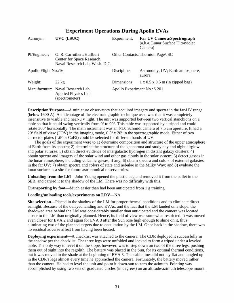
31
Experiment Operations During Apollo EVAs Acronym: UVC (LSUC)
PI/Engineer: G. R. Carruthers/Hurlburt Center for Space Research, Naval Research Lab, Wash. D.C.
Apollo Flight No.:16
Weight: 22 kg
Manufacturer: Naval Research Lab, Applied Physics Lab (spectrometer)
Experiment: Far UV Camera/Spectrograph (a.k.a. Lunar Surface Ultraviolet Camera)
Other Contacts: Thornton Page/JSC
Discipline: Astronomy, UV; Earth atmosphere, aurora
Dimensions: 1 x 0.5 x 0.5 m (in zipped bag)
Apollo Experiment No.: S 201
Description/Purpose—A miniature observatory that acquired imagery and spectra in the far-UV range (below 1600 A). An advantage of the electronographic technique used was that it was completely insensitive to visible and near-UV light. The unit was supported between two vertical stanchions on a table so that it could swing vertically from 0º to 90º. This table was supported by a tripod and could rotate 360º horizontally. The main instrument was an f/1.0 Schmidt camera of 7.5 cm aperture. It had a 20º field of view (FOV) in the imaging mode, 0.5º x 20º in the spectrographic mode. Either of two corrector plates (LiF or CaF2) could be selected for different bands of UV.
The goals of the experiment were to 1) determine composition and structure of the upper atmosphere of Earth from its spectra; 2) determine the structure of the geocorona and study day and night airglow and polar aurorae; 3) obtain direct evidence of intergalactic hydrogen in distant galaxy clusters; 4) obtain spectra and imagery of the solar wind and other gas clouds in the solar system; 5) detect gasses in the lunar atmosphere, including volcanic gasses, if any; 6) obtain spectra and colors of external galaxies in the far UV; 7) obtain spectra and colors of stars and nebulae in the Milky Way; and 8) evaluate the lunar surface as a site for future astronomical observatories.
Unloading from the LM—John Young opened the plastic bag and removed it from the pallet in the SEB, and carried it to the shadow of the LM. There was no difficulty with this.
Transporting by foot—Much easier than had been anticipated from 1 g training.
Loading/unloading tools/experiments on LRV—NA
Site selection—Placed in the shadow of the LM for proper thermal conditions and to eliminate direct sunlight. Because of the delayed landing and EVAs, and the fact that the LM landed on a slope, the shadowed area behind the LM was considerably smaller than anticipated and the camera was located closer to the LM than originally planned. Hence, its field of view was somewhat restricted. It was moved even closer for EVA 2 and again for EVA 3 after the Sun rose high enough to shine on it, thus eliminating two of the planned targets due to occultation by the LM. Once back in the shadow, there was no residual adverse affect from having been heated.
Deploying experiment—A checklist was attached to the camera. The CDR deployed it successfully in the shadow per the checklist. The three legs were unfolded and locked to form a tripod under a leveled table. The only way to level it on the slope, however, was to step down on two of the three legs, pushing them out of sight into the regolith. The battery was placed in the Sun, for its optimal thermal conditions, but it was moved to the shade at the beginning of EVA 3. The cable lines did not lay flat and tangled up in the CDR's legs almost every time he approached the camera. Fortunately, the battery moved rather than the camera. He had to level the unit and point it down-sun to zero the azimuth. Pointing was accomplished by using two sets of graduated circles (in degrees) on an altitude-azimuth telescope mount.
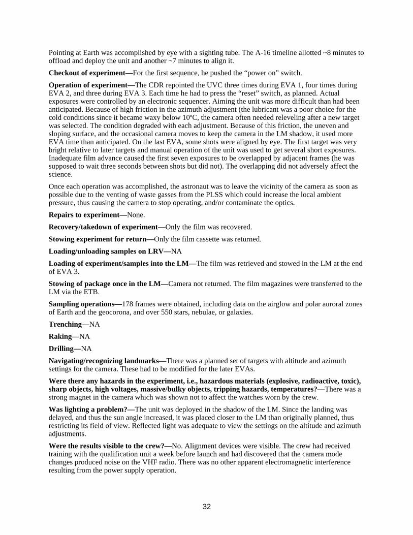
32
Pointing at Earth was accomplished by eye with a sighting tube. The A-16 timeline allotted ~8 minutes to offload and deploy the unit and another ~7 minutes to align it.
Checkout of experiment—For the first sequence, he pushed the “power on” switch.
Operation of experiment—The CDR repointed the UVC three times during EVA 1, four times during EVA 2, and three during EVA 3. Each time he had to press the “reset” switch, as planned. Actual exposures were controlled by an electronic sequencer. Aiming the unit was more difficult than had been anticipated. Because of high friction in the azimuth adjustment (the lubricant was a poor choice for the cold conditions since it became waxy below 10ºC, the camera often needed releveling after a new target was selected. The condition degraded with each adjustment. Because of this friction, the uneven and sloping surface, and the occasional camera moves to keep the camera in the LM shadow, it used more EVA time than anticipated. On the last EVA, some shots were aligned by eye. The first target was very bright relative to later targets and manual operation of the unit was used to get several short exposures. Inadequate film advance caused the first seven exposures to be overlapped by adjacent frames (he was supposed to wait three seconds between shots but did not). The overlapping did not adversely affect the science.
Once each operation was accomplished, the astronaut was to leave the vicinity of the camera as soon as possible due to the venting of waste gasses from the PLSS which could increase the local ambient pressure, thus causing the camera to stop operating, and/or contaminate the optics.
Repairs to experiment—None.
Recovery/takedown of experiment—Only the film was recovered.
Stowing experiment for return—Only the film cassette was returned.
Loading/unloading samples on LRV—NA
Loading of experiment/samples into the LM—The film was retrieved and stowed in the LM at the end of EVA 3.
Stowing of package once in the LM—Camera not returned. The film magazines were transferred to the LM via the ETB.
Sampling operations—178 frames were obtained, including data on the airglow and polar auroral zones of Earth and the geocorona, and over 550 stars, nebulae, or galaxies.
Trenching—NA
Raking—NA
Drilling—NA
Navigating/recognizing landmarks—There was a planned set of targets with altitude and azimuth settings for the camera. These had to be modified for the later EVAs.
Were there any hazards in the experiment, i.e., hazardous materials (explosive, radioactive, toxic), sharp objects, high voltages, massive/bulky objects, tripping hazards, temperatures?—There was a strong magnet in the camera which was shown not to affect the watches worn by the crew.
Was lighting a problem?—The unit was deployed in the shadow of the LM. Since the landing was delayed, and thus the sun angle increased, it was placed closer to the LM than originally planned, thus restricting its field of view. Reflected light was adequate to view the settings on the altitude and azimuth adjustments.
Were the results visible to the crew?—No. Alignment devices were visible. The crew had received training with the qualification unit a week before launch and had discovered that the camera mode changes produced noise on the VHF radio. There was no other apparent electromagnetic interference resulting from the power supply operation.

33
Would you recommend any design changes?—New lubricant for azimuth bearing ring. Also, include this during tests of the instrument in environment chamber.
The backup unit to A-16 was flown on Skylab 4. The unit was modified by removing the tripod and sealing it so that the internal atmosphere would not coat the optics. The mirror was also coated with Al + MgF2 rather than rhenium, as on the A-16 model. A clamp was added so that it could be mounted to the Apollo Telescope Mount while on EVA. Images of the comet Kohoutek were thus obtained. For this operation it was pointed by eye. This experiment was called S201K. It was also used by placing it in the scientific airlock, during which there were mirrors used (articulated mirror system) to enable pointing the FOV at the targets. During this general operation it was called S201G. After some time, the mirrors got clouded by contamination from Skylab.
In the spectrographic mode, the PI recommended that future instruments include a coarse, venetian-blind collimator (a few degrees FWHM) ahead of the grid collimator.
Were any special tools required?—No.
Was the orientation of the experiment (i.e. horizontal/vertical) important? Difficult?—It was important and very difficult. Setting the azimuth on EVA 3 moved the camera off level because of the torque force required. In several realignments, it was impossible to move the leveling bubble to the center of the ring because of the geometry of the three camera legs on the slopes and the time available for releveling.
Was the experiment successful?—Yes.
Were there related experiments on other flights? Apollo? Other?—UV telescopes have flown in Earth orbit. One example was the Orbiting Astronomical Observatory. Hand-held photography of the Earth and Moon was performed during many of the Apollo flights. On A-17 a far UV spectrometer in the SIM Bay of the service module, which was primarily used to study lunar atmospheric density and composition while in lunar orbit, was also used during TEC to observe Earth's atmosphere, zodiacal light, and galactic and extragalactic sources. As mentioned under “design changes” above, the backup unit to A-16 was flown on Skylab 4. An extreme UV survey experiment flew on the Apollo-Soyuz test flight.
Where was it stored during flight?—Quad III of the LM, SEB.
Were there any problems photographing the experiment?—No. Photos clearly show the unit deployed on the surface. Some scattering of far UV light in the photos of the Magellanic cloud was attributed to lunar dust electrostatically suspended above the surface. See also “Lunar Dust Detector DTREM.”
What pre-launch and cruise requirements were there? Power, thermal, late access, early recovery?—A major requirement was to avoid gas contamination of the photocathode. The unit was placed into a bag. The bag was then purged with dry nitrogen continuously until 72 hours before launch to keep out moisture while on the launch pad. The bag must have vented upon launch. The mass of this bag is included in the 22 kg.
What was different between training and actual EVA?—The Sun angle was different than planned and trained under.
What problems were due to the suit rather than the experiment?—No.
Any experiences inside the LM of interest from the experiment/operations viewpoint?—No.
References:
A-46 Preliminary Science Report, NASA SP-315, 1972
A-16 Mission Report
Apollo Scientific Experiments Data Handbook, JSC-09166, NASA TM X-59131, August 1974, in JSC History Office
Page, T. and G. R. Carruthers, S201 Far Ultraviolet Atlas of the Large Magellanic Cloud, NRL Report 8206, 1978

34
George R. Carruthers, “Apollo 16 Far-Ultraviolet Camera/Spectrograph: Instrument and Operations, Applied Optics,” Vol. 12, p. 2501 - 2508, Oct. 1973
Thornton Page, personal communication with Thomas Sullivan
Thornton Page, “S201 Far-Ultraviolet Photographs of Comet Kohoutek From Skylab 4 (SL4), Preliminary Report,” in Comet Kohoutek, Proceedings of a Workshop held at MSFC, June 13-14 1974, pp. 37-75
Apollo 16 Final Lunar Surface Procedures, March 16, 1972, MSC
Apollo Program Summary Report, section 3.2.31 Far-Ultraviolet Camera/Spectrograph, JSC-09423, April 1975
Apollo 16 Technical Crew Debriefing, 5 May 1972, in JSC History Office
Figure 9: Far UV camera deployed in the LM shadow (AS-16-114-18439).

35
Experiment Operations During Apollo EVAs Acronym: LSG
PI/Engineer: Joseph Weber/ University of Maryland
Apollo Flight No.:17
Weight: 12.7 kg
Manufacturer: Univ./Maryland & Bendix
Experiment: Lunar Surface Gravimeter a.k.a. Lunar Tidal Gravimeter
Other Contacts: John. J. Giganti, J. V. Larsen J. P. Richard/University of Maryland
Discipline: Space physics, lunar geology, lunar gravimetry
Dimensions: 27.7 x 25.4 x 38.4 cm, stowed plus a 7.6 cm (dia.) cable reel
Apollo Experiment No.: S 207
Description/Purpose—This was designed to make very accurate (1 part in 1011) measurements of the lunar gravity and of its variation with time. It was essentially a sensitive spring balance, and also functioned as a one-axis seismometer. It was considered part of the ALSEP. Its intent was to measure gravity waves by using the Moon as an antenna and also investigate tidal distortions of the shape of the Moon. Following deployment of the gravimeter, problems occurred in trying to balance the beam. These problems were caused by a mathematical error in the sensor mass weights. Several reconfigurations of the instrument were made during the previous year.
Unloading from the LM—As part of ALSEP.
Transporting by foot or MET—As part of ALSEP.
Loading/unloading tools/experiments on LRV—NA
Site selection—Part of ALSEP, ~8 m from the central station.
Deploying experiment—As part of ALSEP on EVA 1. After releasing it from the subpallet with the UHT, it was carried (using the UHT) to its site. The crew had to raise and tilt a sunshade, set the instrument on a firm surface with approximate orientation, level and align it using a bubble and shadowgraph, perform initial uncaging, and report level and alignment. It was planned to take ~3 minutes. There were no known anomalies in the deployment of the LSG that would account for the problems encountered upon the commanded activation of the experiment.
Checkout of experiment—It was discovered on EVA 2 that the sensor beam of the LSG could not be nulled (using the micrometer screw adjustment of the instrument), even though the LMP reverified that the instrument was level and the gimbal was free. Later analysis showed a design (arithmetic) error of the sensor mass weights. They were ~2% lighter than the proper nominal weight for 1/6 g operation of the flight unit. The sensor mechanism allowed up to only 1.5% adjustment from the nominal for possible inaccuracies. The error was made in the conversion calculations from 1 g to 1/6 g for the flight unit by including an erroneous value in the calculations from the uncorrected calculations for the qualification unit.
Operation of experiment—From JSC via the ALSEP command system. After determining the design error in the instrument, it was reconfigured to obtain long-term seismic and free-mode science data. However, the sensitivity of the system was considerably reduced.
Repairs to experiment—Attempted on EVA 2 and 3, but unsuccessful due to design error. The LMP rapped the exposed top plate on the gimbal; rocked the experiment in all directions; releveled the instrument, working the base well against the surface; and verified the sunshade tilt. These actions were taken to free a mass assembly or a sensor beam that was suspected of being caught or bound, but no change was apparent. The problem was at least partly overcome by applying pressure on the beam with the mass-changing mechanism beyond the design point by addition of all included masse so that it contacted the beam. Much valuable EVA time (~30 minutes) was spent on the attempt.
36
Recovery/takedown of experiment—NA
Stowing experiment for return—NA
Loading/unloading samples on LRV—NA
Loading of experiment/samples into the LM—NA
Stowing of package once in the LM—NA
Sampling operations (soil, rocks)—NA
Trenching—NA
Raking—NA
Drilling—NA
Navigating/recognizing landmarks—NA
Were there any hazards in the experiment, i.e., hazardous materials (explosive, radioactive, toxic), sharp objects, high voltages, massive/bulky objects, tripping hazards, temperatures?—No.
Was lighting a problem?—NA
Were the results visible to the crew?—Instrument level and gimbal release were visible.
Would you recommend any design changes?—Yes. The PI considered his experiment proprietary and was able to bypass NASA reviews and supply his experiment as a “black box.” Perhaps the design error would have been caught in the proper reviews if they focused on the technical aspects of the device, but not if they only looked for hazards.
Were any special tools required?—The UHT was used during deployment. It was also used later to attempt to jar the gimbal loose during a repair attempt.
Was the orientation of the experiment (i.e. horizontal/vertical) important? Difficult?—The unit needed to be leveled.
Was the experiment successful?—No, but the signals received were processed and analyzed for seismic, free mode, and gravity wave information.
Were there related experiments on other flights? Apollo? Other?—There was also a traverse gravimeter (S 199) on A-17 which took 7 measurements on the 1st EVA, 7 on the 2nd, and 9 on the 3rd. Orbital measurements of mascons were made in several orbital missions, both manned and unmanned. There were also seismic experiments (S 031 and S 033) performed on landed missions.
Where was it stored during flight?—As part of the ALSEP.
Were there any problems photographing the experiment?—No.
What pre-launch and cruise requirements were there? Power, thermal, late access, early recovery?—None.
What was different between training and actual EVA?—No comments by crew.
What problems were due to the suit rather than the experiment?—No comments by crew.
Any experiences inside the LM of interest from the experiment/operations viewpoint?—No.
References:
A-17 Preliminary Science Report
Apollo 17 Mission Report
Apollo Lunar Surface Experiments Package - Apollo 17 ALSEP (Array E) Familiarization Course -Handout for class of 1 September 1972, in JSC History Office

37
Apollo Scientific Experiments Data Handbook, JSC-09166, NASA TM X-58131, August 1974, in JSC History Office
Apollo Program Summary Report, section 3.2.15 Lunar Surface Gravimeter Experiment, JSC-09423, April 1975
Apollo 17 Final Lunar Surface Procedures, Vol. 1: Nominal Plans, MSC, 11/6/72
ALSEP Array E Critical Design Review Presentation Material, NASA/MSC - Bendix. Aerospace Systems Division, NAS9-5829, 14 - 18 June 1971, at JSC History Office
ALSEP Termination Report, NASA Reference Publication 1036, April 1979
Figure 10: The LSG deployed at the Apollo 17 ALSEP site. The sunshield is tipped
appropriately for the latitude of the site. The central station, RTG, and LM are visible in the background (AS-17-134-20501).

38
Experiment Operations During Apollo EVAs Acronym: TGE
PI/Engineer: Manik Talwani/ Columbia University
Apollo Flight No.: 17
Weight: 14.6 kg
Manufacturer: MIT/Draper Lab
Experiment: Traverse Gravimeter Experiment
Other Contacts: George Thompson, Brian Dent Stanford University
Discipline: Space physics, lunar geology, lunar gravimetry
Dimensions: 50.8H x 27.9W x 24.8 cm deep
Apollo Experiment No.: S 199
Description/Purpose—The primary goal of the TGE was to make relative gravity measurements at a number of locations in the A-17 landing area and to use these to obtain information about the geological substructure. A secondary goal was to obtain the value of the gravity at the landing site relative to an accurately known value on Earth. The gravity sensor used was a Bosch Arma D4E vibrating string accelerometer. It was a double-stringed instrument. The sensor was mounted on a gimbaled frame. Two vertical pendulums mounted on the frame sensed departures from vertical through comparator circuits, which drove motors to level the unit-up to 20 seconds was required in the normal mode and between 90 - 130 seconds in the bias mode (instrument inverted). The TGE could be leveled only if it was initially placed in a position less than 15º from level. The entire unit was housed in a cylindrical box with a flat rear surface. The battery powered unit had three feet, a handle for carrying, and a cover over the display/control panel.
Unloading from the LM—With ALSEP pallets.
Transporting by foot or MET—NA
Loading/unloading tools/experiments on LRV—It rode on the geopallet at the back of the LRV. Between EVA periods, the unit was placed in the shade with the radiator open.
Site selection—The field geology stations on the planned traverses were used to obtain the TGE measurements. Several measurements around the LM were also made.
Deploying experiment—Measurements were made both with the TGE mounted on the LRV and with it placed on the surface. One reading was made at the start and end of each EVA.
Checkout of experiment—Several runs near LM, and on and off the LRV, were performed to check the operation of the instrument.
Operation of experiment—A network of gravity measurements at 12 sites spread across the valley floor (and one gravimeter bias measurement) were obtained during EVAs on A-17. Six measurements (and the bias) were made on EVA 1, seven on EVA 2, and four on EVA 3, spread out among several stations and near the LM (some were duplicates). A measurement was initiated by depressing the “GRAV” button. The cycle started by leveling then went into the measurement mode. To obtain the bias measurement, a separate button was pushed, and a similar sequence ensued. It had to be left undisturbed during its operating cycle. The reading was displayed on the display and stayed on for 20 seconds. It could be redisplayed by pushing the “READ” button once the crewman had time to read it. A toggle switch selected ON or STANDBY for power conservation.
The TGE team strongly wanted to impose a constraint which would not allow the LRV TV camera to be aimed during the gravimeter's operating cycle because of vibrations. The geology team was just as strongly opposed to not being able to see what the crew was doing every minute at a station, or not being able to see some potentially interesting rock and directing the crew's attention to it. The gravimeter team was hard pressed to specify exactly what constituted an “unacceptable” vibration level. A great deal of analytical work went into trying to prove what the vibration levels would be, and it was finally necessary to instrument an engineering model of the LRV with accelerometers in the vacuum chamber. The vibration from the moving camera proved to be negligible and the “constraint” went away.
39
Repairs to experiment—None required. Note that the pallet on which the TGE sat in the LRV swung open before measurement 25 and the resultant banging of the pallet may have caused problems resulting in an erroneous reading.
Recovery/takedown of experiment—Left on the surface.
Stowing experiment for return—NA
Loading/unloading samples on LRV—It was mounted on a pallet. There was a folding handle on top of the unit. Cam latches on the sides of the handles secured it to the LRV pallet when the handle was pressed down toward the rear of the unit.
Loading of experiment/samples into the LM—NA
Stowing of package once in the LM—NA
Sampling operations (soil, rocks)—NA
Trenching—NA
Raking—NA
Drilling—NA
Navigating/recognizing landmarks—NA
Were there any hazards in the experiment, i.e., hazardous materials (explosive, radioactive, toxic), sharp objects, high voltages, massive/bulky objects, tripping hazards, temperatures?—Power was supplied by a 7.5 V battery.
Was lighting a problem?—No.
Were the results visible to the crew?—Yes. A display panel read out gravity and oven temperature values.
Would you recommend any design changes?—No comments by crew.
Were any special tools required?—No.
Was the orientation of the experiment (i.e. horizontal/vertical) important? Difficult?—Yes, level was important, but the astronaut only had to have it level to 15º, the instrument did the rest.
Was the experiment successful?—Yes.
Were there related experiments on other flights? Apollo? Other?—There was a stationary LSG (S 207) on A-17. Also, orbital measurements of mascons were made during several manned and unmanned missions. The accelerometers of all LMs which landed measured a value of lunar g after landing.
Where was it stored during flight?—LM Quad 111, experiment pallet.
Were there any problems photographing the experiment?—No.
What pre-launch and cruise requirements were there? Power, thermal, late access, early recovery?—None reported.
What was different between training and actual EVA?—No comments by crew.
What problems were due to the suit rather than the experiment?—Operating the unit on the surface, as opposed to on the LRV, was difficult because it was very low and the suit made it hard to lean over and press the buttons. Gene Cernan tended to put it down near the LRV so that he could lean on it to reach the experiment, or if on a slope, stand down-slope. Leaning on a scoop might have worked, too.
Any experiences inside the LM of interest from the experiment/operations viewpoint?—No.
References: A-17 Preliminary Science Report
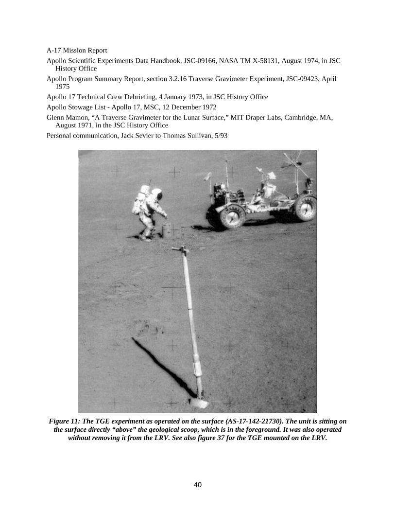
40
A-17 Mission Report Apollo Scientific Experiments Data Handbook, JSC-09166, NASA TM X-58131, August 1974, in JSC
History Office Apollo Program Summary Report, section 3.2.16 Traverse Gravimeter Experiment, JSC-09423, April
1975 Apollo 17 Technical Crew Debriefing, 4 January 1973, in JSC History Office Apollo Stowage List - Apollo 17, MSC, 12 December 1972 Glenn Mamon, “A Traverse Gravimeter for the Lunar Surface,” MIT Draper Labs, Cambridge, MA,
August 1971, in the JSC History Office Personal communication, Jack Sevier to Thomas Sullivan, 5/93
Figure 11: The TGE experiment as operated on the surface (AS-17-142-21730). The unit is sitting on
the surface directly “above” the geological scoop, which is in the foreground. It was also operated without removing it from the LRV. See also figure 37 for the TGE mounted on the LRV.

41
Experiment Operations During Apollo EVAs Acronym: HFE
PI/Engineer: Marcus G. Langseth/ Columbia University
Apollo Flight No.:15, (16), 17
Weight: 9.9 kg, total; 4.6 kg, electronics box
Manufacturer: Columbia University, Arthur D. Little, Martin-Marietta
Experiment: Heat Flow Experiment
Other Contacts: Sydney P. Clark, Jr.[Yale J.L. Chute, Jr., S. J. Keihm/ Lamont-Doherty Geological Observatory
Discipline: Lunar geology, heat flow
Dimensions: Probes - 4 x 50 cm segments (stowed 8.6 x 11.4 x 64.8 cm); electronics box 28 x 25 x 24 c
Apollo Experiment No.: S 037
Description/Purpose—This experiment was designed to make temperature and thermal-property measurements in the lunar subsurface in order to determine the rate at which heat flows out of the interior of the Moon. This heat loss is directly related to the rate of internal heat production and to the internal temperature profile; hence the measurements resulted in information about the abundances of long-lived radioisotopes within the Moon and increased the understanding of the thermal evolution of the body.
The essential measurements were made by two slender temperature-sensing probes that were placed in pre-drilled holes in the subsurface (the borestems were left in the ground, as well), spaced -10 m apart. Each probe consisted of two nearly identical 50-cm-long sections. Each section of each heat flow probe had two accurate (+/-0.001 K) differential thermometers that measured temperature differences between points separated by 47 and 28 cm. The probe segments also contained heaters which provided heat to measure the thermal conductivity. The electronics were contained in a separate box which rested on the lunar surface and was connected to the ALSEP central station.
Unloading from the LM—As part of the ALSEP.
Transporting by foot or MET—As part of the ALSEP.
Loading/unloading tools/experiments on LRV—NA
Site selection—The electronics package was placed 7.6 to 9.1 m north of the central station, at least 3 m from all other experiments, and at least 6 m from the PSE. Two holes needed to be drilled for emplacement of the probes below the surface. These were located 4.6 - 5.8 m from the electronics package and ~7.6 m from the RTG. Also, the holes/probes needed to be at least 60 m from fresh craters with surrounding stones and at least 5 diameters from large isolated boulders > 0.7 m across exposed at the surface.
A third constraint on the placement of the probes (although it may not have ever been documented) was that they not be deployed within one crater radius of large old craters. A few weeks before the mission, the PI worried that the official target point for the landing was too close to the crater Camelot and that the effects of the crater topography would cause the heat flow data to be skewed. Although one can correct for topography, it adds uncertainty to the data that could be avoided. A change in the landing coordinates (stored in the computer) at that late date was unheard of. The PI did let his concerns be known at NASA Headquarters and it eventually made its way to Cernan whose reaction was, “No problem, I'll simply redesignate a little short if necessary to stay one crater radius short of the rim of Camelot.” The important thing, as far as the crew was concerned, was to get the very best data possible for this experiment on the last opportunity to do so. They did, indeed, land short by the necessary distance, although it is unclear whether it was necessary to redesignate.
42
Deploying experiment—The general operation involved assembling the first two bore stems, inserting them into the drill chuck, and drilling into the surface until about one-third of a section protruded above the surface. Using a wrench, the chuck was released and the drill was removed. A second pair of bore stems was assembled and attached to those already emplaced in the surface. The drill chuck was reset and the drill placed atop the new bore stem sections and the total bore stem assembly was drilled further until again about one-third of a section remained above the surface. The procedure was repeated for a third pair of bore stems until ~15 cm remained above the surface. The drill was then removed and the HFE probe was inserted as far as possible into the bore stem using the emplacement tool. The depth of penetration was indicated by markings on the tool. The drill and rack were carried to the second probe site and the entire procedure was repeated. The timeline for A-15 planned ~61 minutes for the entire activity. A-16 allotted 64 minutes.
On A-15, drilling the holes to emplace the probes was more difficult than had been expected. The resistant nature of the subsurface or the poor bore stem design prevented penetration to the planned depth of 3 m. Instead, at the probe 1 site, the bore stem penetrated 1.62 m; and, at probe site 2, the bore stern penetrated 1.60 m. An obstruction, probably a break in the stem at a depth of 1 m, prevented probe 2 from passing to the bottom of the borestem. This “break” may have been caused by pulling up on the bore stem, causing a decoupling of the segments. Because of the very large temperature differences over the upper section, no valid temperature measurements were obtained by the upper section of this probe. Probe 1 was inserted 140 cm into the bore stem. The crew had to report probe depth, stem height, and thermal shield depth during the activities.
On A-16, the first hole was drilled and the probe inserted successfully, but the cable connecting the electronics package to the central station was then inadvertently pulled loose from the connector on the central station when the CDR caught his foot in the loose cable. The cable had looped and become snagged on a boot. This rendered the experiment useless and drilling of the second hole was eliminated. The CDR did not know that the cable had broken because pressure suit mobility is restrictive and he could not normally see his lower legs or feet. The mission report pointed out that it was well known that the ALSEP package cables had memory and stood off the surface in low g. This condition required a crewman to jump clear of cables which he could not adequately see.
Both probes were successfully inserted to their full depth on A-17. Probe 1 went to 2.36 m and probe 2 went to 2.3 m. A photo shows the CDR on his knees while inserting the probe into the hole (although he needed a “prop” to kneel).
Checkout of experiment—From Earth.
Operation of experiment—From JSC via the ALSEP command system. Platinum resistors provided heat, and the temperature rise at known distances from these heaters was measured via thermocouples. With the heaters off, the diurnal temperature cycle was measured at known depths.
Repairs to experiment—See drilling. After the cable broke on A-16, it could not be repaired. The incident precipitated the inclusion of strain relief in the cable connectors on the A-17 instruments. A contingency plan existed to place the probes in a trench if the drilling was difficult, but this was not performed.
Recovery/takedown of experiment—NA
Stowing experiment for return—NA
Loading/unloading samples on LRV—NA
Loading of experiment/samples into the LM—NA
Stowing of package once in the LM—NA
Sampling operations (soil, rocks)—NA
Trenching—NA
Raking—NA

43
Drilling—During the drilling, the bore stems were drilled into the surface in sections. After the first was drilled in partway, a wrench was used to release the chuck from the stem, the second section was screwed into the lower section, and the drill attached to this upper section. This process was repeated to attach the third section. The holes were to be within 15º of vertical, as visually determined by the astronaut once the probes were inserted. The cores were left in place.
Drilling the second hole for the heat flow probe on A-15 proved difficult. Because of the high torque levels on the chuck-stem interface, the drill chuck bound to the stem; in one case it was necessary to destroy the stem to remove it from the chuck. A trick to make the operation easier involved putting the wrench onto the stem which was in the ground and holding it in place with an ankle while turning the drill handle to remove it from the bore stem.
Navigating/recognizing landmarks—NA
Were there any hazards in the experiment, i.e. hazardous materials (explosive, radioactive, toxic), sharp objects, high voltages, massive/bulky objects, tripping hazards, temperatures?—During deployment on A-16, the cable was pulled loose of the central station during deployment by tripping. This was due to memory in the cable which did not allow it to lie flat, causing a tripping hazard. This was evident during training but not corrected. On A-15, David Scott had also tripped over one of the wires to the probe and moved the electrical box from its position. It had to be realigned on the next EVA.
Was lighting a problem?—No
Were the results visible to the crew?—Other than the drilling effort and alignment, no.
Would you recommend any design changes?—The drill stem was redesigned based on the A-15 experience. The cable attachments were strengthened for the A-17 instruments so that even the excessive force of tripping over the cable would not pull it loose.
Were any special tools required?—The ALSD. The bore stems had a solid-faced bit (so that a hole would remain open, unlike the core samples where the drill stem filled with regolith) and were made of boron filament reinforced epoxy rather than titanium, for low thermal conductivity. Also, a probe emplacement tool (a.k.a. rammer) was packaged with the two probes in a box separate from the electronics package. It had marks to measure the depth of the probes. A type of Stillson wrench was used to decouple the bore stems from the ALSD chuck.
Was the orientation of the experiment (i.e. horizontal/vertical) important? Difficult?—The electronics package was leveled to within 5º of vertical with the UHT. It was not difficult. Alignment was accomplished with a shadowgraph, using the shadow of the UHT on a decal as a guide.
Was the experiment successful?—On A-15, partially. On A-16, one cable was broken and the hardware became inoperative. On A-17 the experiment was successful.
Were there related experiments on other flights? Apollo? Other?—No.
Where was it stored during flight?—LM MESA.
Were there any problems photographing the experiment?—No.
What pre-launch and cruise requirements were there? Power, thermal, late access, early recovery?—None.
What was different between training and actual EVA?—Drilling effort.
What problems were due to the suit rather than the experiment?—No comments by crew.
Any experiences inside the LM of interest from the experiment/operations viewpoint?—No.
References: Preliminary Science Reports for A-15, 16, 17 Mission Reports for A-15, 16, 17

44
Apollo Lunar Surface Experiments Package - Apollo 17 ALSEP (Array E) Familiarization Course handout for class of 1 September 1972, in JSC History Office
Apollo Scientific Experiments Data Handbook, JSC-09166, NASA TM X-58131, August 1974, in JSC History Office
Apollo 15 Final Lunar Surface Procedures, JSC, July 9, 1971 Apollo 16 Final Lunar Surface Procedures, March 16, 1972, MSC Apollo 17 Final Lunar Surface Procedures, Vol. 1: Nominal Plans, MSC, 11/6/72 Apollo Program Summary Report, section 3.2.14 Heat Flow Experiment, JSC-09423, April 1975 Apollo 15 Technical Crew Debriefing, 14 August 1971, in JSC History Office ALSEP Termination Report, NASA Reference Publication 1036, April 1979 “Lunar Sourcebook - A User's Guide to the Moon,” G. Heiken, D. Vaniman, and B. French, Eds.,
Cambridge University Press, Cambridge, 1991 Personal communication, Jack Sevier to Thomas Sullivan, May 1993
Figure 12: The HFE during emplacement on Apollo 15. The drill rack is in the foreground
and the ALSD is on the surface behind the borestem, which is emplaced in the ground. The dark, two-segment rod in the left hand of the crewman is the heat probe. The white probe emplacement
tool is in his right hand (AS-15-92-12407).

45
Experiment Operations During Apollo EVAs Acronym: LRRR, LR3
PI/Engineer: James E. Faller/ Wesleyan University
Apollo Flight No.: 11, 14, 15
Weight: 9 A-11 23.59 kg; A-14 20.41 A-15 36.20
Manufacturer: Bendix
Experiment: Laser Ranging Retroreflector
Other Contacts: C. 0. Alley/University of Maryland
Discipline: Earth/Moon system
Ht W-stwd W-dplyd Lngth Dimensions: 29.2 cm 68.6 68.6 66.0 30.0 63.8 63.8 64.8 30.0 69.5 105.2 64.8
Apollo Experiment No.: S 078
Description/Purpose—An optical comer reflector to measure lunar librations (both in latitude and longitude), the recession of the moon from the Earth due to tidal dissipation, and the irregular motion of the Earth, including the Chandler wobble of the poles. This is accomplished by using the technique of short-pulse laser ranging. The LRRR of A-14 differed in only main design aspects from that on A-11. The LRRR on A-15 was the largest, with 300 separate sub-reflectors-the previous two had only 100. The A-15 array consisted of a hinged, two-panel assembly (204 and 94 reflectors) mounted on a leg assembly, which was deployed by the astronaut. The larger array was to allow smaller telescopes on Earth to receive signals from it, but a report on 31 July, 1971, showed that the larger array was comparable, but not superior, to the smaller arrays.
Unloading from the LM—No comments by crew.
Transporting by foot or MET—Carried by hand on A-11 to balance the PSEP package in the other hand. Also carried by hand on A-14 while pulling the MET.
Loading/unloading tools/experiments on LRV—On A-15 it was carried on the LMP's seat of the LRV, held in place with the seat belt, and driven to the deployment site. The LMP was carrying the ALSEP at the time.
Site selection—Generally flat and level area, 300 to 500 feet due W of the LM. Greater than 500 feet was requested to minimize the dust from LM ascent.
Deploying experiment—Carried by hand (along with the PSEP on A-11) to the deployment site. The leveling leg, deployed by the astronaut by pulling a pin, provided the proper elevation angle for each site. It was tilted and then rested on the surface using the UHT. It was pointed towards the Earth. The bubble used to level the device on A-11 showed it to be within 0.5º of level, with the bubble oriented to the SW. A sun-compass allowed azimuthal alignment of the array with respect to the Sun. After these steps, the dust cover was removed. There was no trouble deploying the A-14 or 15 LRRR, either. The operations sequence on A-15 was slightly different, but essentially the same tasks were performed. A typical timeline from A-15 shows ~6 minutes for deploying the experiment.
Checkout of experiment—Range measurements to the A-14 LRRR (from Earth) were successfully accomplished on the day it was deployed. Measurements taken after LM liftoff indicate that the ascent stage engine bum caused no serious degradation of the LRRR reflective properties.
Operation of experiment—None, it is passive.
Repairs to experiment—NA
Recovery/takedown of experiment—NA
Stowing experiment for return—NA
Loading/unloading samples on LRV—NA
Loading of experiment/samples into the LM—NA

46
Stowing of package once in the LM—NA
Sampling operations (soil, rocks)—NA
Trenching—NA
Raking—NA
Drilling—NA
Navigating/recognizing landmarks—NA
Were there any hazards in the experiment, i.e. hazardous materials (explosive, radioactive, toxic), sharp objects, high voltages, massive/bulky objects, tripping hazards, temperatures?—No.
Was lighting a problem?—NA
Were the results visible to the crew?—The unit had a gnomon and bubble leveling device for the astronaut to use during deployment. The results of the experiment were not visible to the crew.
Would you recommend any design changes?—The overall design for the A-14 and A-15 reflector arrays was similar to that for A-11 except that the half-angle taper of the reflector cavities was increased so as to increase the array optical efficiency 20 to 30 percent for off-axis Earth positions. The number of reflectors in the array was increased for A-15 to permit regular observations with simpler ground equipment.
Were any special tools required?—UHT.
Was the orientation of the experiment (i.e. horizontal/vertical) important? Difficult?—Very
important, but not difficult. It was aimed at Earth and leveled to within 5º. Alignment was reported by noting where the shadow was cast on index marks by the gnomon. These marks were set for a specific landing site and deployment date.
Was the experiment successful?—Yes.
Were there related experiments on other flights? Apollo?—A-11, 14, 15 all had LRRR. A French-Russian array was carried on Luna 17. Two LAGEOS satellites were launched by the Shuttle (into high orbits within the Van Allen belts?).
Where was it stored during flight?—On A-11 it was stored in LM SEB/Quad 11. A-14 stored it in Quad 1. A-15 in Quad 111.
Were there any problems photographing the experiment?—No.
What pre-launch and cruise requirements were there? Power, thermal, late access, early recovery?—None.
What was different between training and actual EVA?—No comments by crew.
What problems were due to the suit rather than the experiment?—No comments by crew.
Any experiences inside the LM of interest from the experiment/operations viewpoint?—No.
References:
Preliminary Science Reports for A-11, 14, 15
Apollo Scientific Experiments Data Handbook, JSC-09166, NASA TM X-58131, August 1974, in JSC History Office
Apollo Program Summary Report, section 3.2.19, Laser Ranging Retroreflector Experiment, JSC09423, April 1975
ALSEP Termination Report, NASA Reference Publication 1036, April 1979

47
Figure 13: The LRRR as deployed at the Apollo 14 site. Note the bubble level and the shadow graph for orientation. These were set for the landing site location prior to launch (AS14-67-9385). See also
figure 8 for a method of carrying the LRRR.

48
Experiment Operations During Apollo EVAs Acronym: LACE (LMS)
PI/Engineer: John H. Hoffman/ University of Texas/Dallas
Apollo Flight No.: 17
Weight: 9.1 kg
Manufacturer: Univ. of Texas/Dallas, Bendix
Experiment: Lunar Atmospheric Composition Experiment (a.k.a. Lunar Mass Spectrometer)
Other Contacts: Dallas E. Evans/JSC R.R. Hodges, Jr. & F.S. Johnson/U. T./Dallas
Discipline: Lunar atmosphere
Dimensions: 33.7 x 16.5 x 31.8 cm
Apollo Experiment No.: S 205
Description/Purpose—The LACE was a 3-channel mass spectrometer designed to identify the composition of, and variation in, the lunar atmosphere. Its mass range was from 1-to-110 amu. It consisted of a magnetic deflection mass spectrometer, an electronics portion, and a dust cover which was not commanded open until the last explosive charge of the LSPE was detonated, 6 days after deployment.
Unloading from the LM—As part of ALSEP.
Transporting by foot or MET—As part of ALSEP - see ALSEP - General Information.
Loading/unloading tools/experiments on LRV—NA
Site selection—As part of ALSEP
Deploying experiment—The crew had to open a vent valve, remove three fasteners, rotate the unit upright, place it 45 feet NW of the central station, level it with a bubble, break the hermetic seal on the sensor, and recheck the level. The entrance aperture was oriented upward to intercept and measure the downward flux of gasses at the lunar surface-atoms and molecules have a ballistic trajectory under lunar conditions. This was sealed by a ceramic cap until opened by the crew. An arrow (Sun orientation) and bubble level aided deployment.
Checkout of experiment—From Earth.
Operation of experiment—From JSC via the ALSEP command system. It could not be operated in the lunar daytime because the electronics could not take the heat.
Repairs to experiment—None required or attempted.
Recovery/takedown of experiment—NA
Stowing experiment for return—NA
Loading/unloading samples on LRV—NA
Loading of experiment/samples into the LM—NA
Stowing of package once in the LM—NA
Sampling operations (soil, rocks)—NA
Trenching—NA
Raking—NA
Drilling—NA
Navigating/recognizing landmarks—NA

49
Were there any hazards in the experiment, i.e. hazardous materials (explosive, radioactive, toxic), sharp objects, high voltages, massive/bulky objects, tripping hazards, temperatures?—High voltages in the instrument were not turned on until after departure.
Was fighting a problem?—No.
Were the results visible to the crew?—Just level and alignment.
Would you recommend any design changes?—None made by crew.
Were any special tools required?—UHT for deployment.
Was the orientation of the experiment (i.e. horizontal/vertical) important? Difficult?—The entrance aperture was oriented upward to intercept and measure the downward flux of gasses at the lunar surface. It only needed to be within 15º of level. The bubble level made this easy. An arrow aided the orientation of the instrument toward the Sun.
Was the experiment successful?—Yes, although an error in thermal design and temperature-sensitive components limited its operation to temperatures <325 K, which precluded operation during elevated lunar day temperatures when the atmosphere would have been most prevalent.
Were there related experiments on other flights? Apollo? Other?—The CCIG (S059) on A-12, 14, & 15 was limited to total gas concentrations. The mass spectrometer (S-165) in the SIM bay of the SM on A-15 &16 also observed the lunar atmosphere at higher altitudes. Also, the Far Ultraviolet Spectrometer Experiment (S 169) in the SIM Bay of the SM of A-17 was used to measure the lunar atmosphere using resonance line scattering (none found except for a cloud just after LM descent.)
Where was it stored during flight?—As part of ALSEP.
Were there any problems photographing the experiment?—No.
What pre-launch and cruise requirements were there? Power, thermal, late access, early recovery?—None reported.
What was different between training and actual EVA?—No comments by crew.
What problems were due to the suit rather than the experiment?—No comments by crew.
Any experiences inside the LM of interest from the experiment/operations viewpoint?—No comments by crew.
References:
A-17 Preliminary Science Report
Personal conversation with Dallas Evans
Apollo 17 Mission Report
Apollo 17 Final Lunar Surface Procedures, Vol. 1: Nominal Plans, MSC, 11/6/72
Apollo Lunar Surface Experiments Package - Apollo 17 ALSEP (Array E) Familiarization Course handout for class of 1 September 1972, in JSC History Office
Apollo Scientific Experiments Data Handbook, JSC-09166, NASA TM X-58131, August 1974, in JSC History Office
Apollo Program Summary Report, section 3.2.26, Lunar Atmosphere Composition Experiment, JSC-09423, April 1975
ALSEP Array E Critical Design Review Presentation Material, NASA/MSC - Bendix Aerospace Systems Division, NAS9-5829, 14-18 June 1971, JSC History Office
ALSEP Termination Report, NASA Reference Publication 1036, April 1979

50
Figure 14: The LACE instrument deployed at the Apollo 17 ALSEP site. The bubble level and
orientation arrow are visible on the top (AS-17-134-20498).

51
Experiment Operations During Apollo EVAs Acronym: LEAM
PI/Engineer: Otto E. Berg/ Goddard Space Flight Center
Apollo Flight No.: 17
Weight: 7.4 kg
Manufacturer: Bendix
Experiment: Lunar Ejecta and Meteorites
Other Contacts: F. F. Richardson, H. Burton/ Goddard Space Flight Center
Discipline: Lunar geology, cratering, micrometeorites
Dimensions: 32.3 x 30.5 x 19.8 cm, stowed
Apollo Experiment No.: S 202
Description/Purpose—The objectives of the LEAM experiment were to detect secondary particles that had been ejected by meteorite impacts on the lunar surface and to detect primary micrometeorites themselves. The three classes of particles encountered by the LEAM included lunar ejecta, interstellar grains, and cometary debris, all of which can be considered under the title of cosmic dust. The experiment measures particle speed, radiant direction, particle momentum, and particle kinetic energy. The particle detectors of the instrument were multi-layered arrays that were capable of measuring the velocity and energy of incident particles. It consisted of three sensors—east, west, and up. It stood on four legs and was connected to the ALSEP central station by a cable.
Unloading from the LM—As part of ALSEP.
Transporting by foot or MET—As part of ALSEP.
Loading/unloading tools/experiments on LRV—NA
Site selection—As part of ALSEP.
Deploying experiment—As part of ALSEP. The crew had to connect a cable to the central station, remove the instrument from the subpallet, locate it 25 feet SE of the central station, release the legs, and place in on the surface within 5º of level and 5º of alignment, using a bubble and sun dial. As requested, the east sensor was directed 25º north of east to accommodate interstellar grains. It was protected by two dust covers that were removed by ground command using a redundant squib system.
Checkout of experiment—After deployment, it was commanded “on” from Earth for calibration, then turned off until after LM ascent and detonation of the surface charges of the LSPE.
Operation of experiment—Operated from JSC via the ALSEP command system. The dust covers over the sensors were commanded to release in the lunar night, but did not, perhaps because of the cold. They did release sometime during dawn of the second lunation.
Repairs to experiment—None required or attempted.
Recovery/takedown of experiment—NA
Stowing experiment for return—NA
Loading/unloading samples on LRV—NA
Loading of experiment/samples into the LM—NA
Stowing of package once in the LM—NA
Sampling operations (soil, rocks)—NA
Trenching—NA
Raking—NA
Drilling—NA
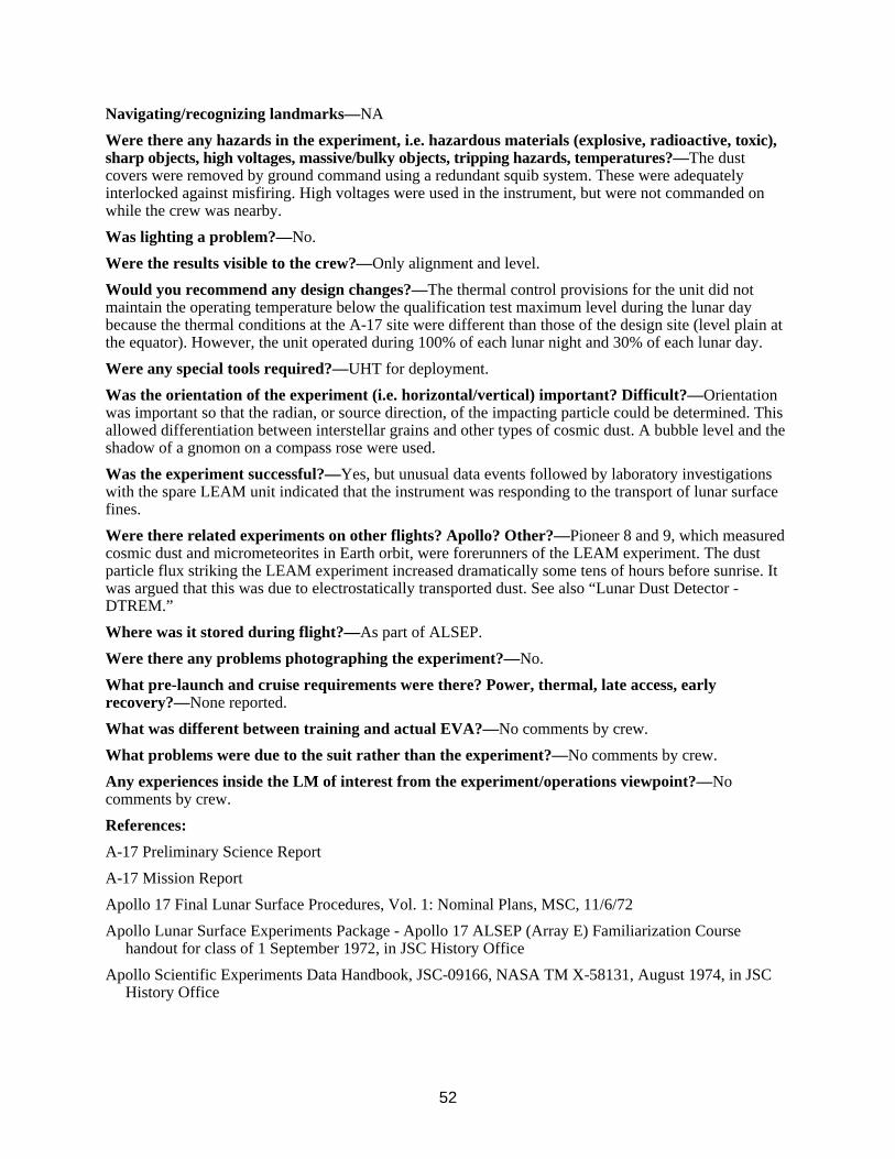
52
Navigating/recognizing landmarks—NA
Were there any hazards in the experiment, i.e. hazardous materials (explosive, radioactive, toxic), sharp objects, high voltages, massive/bulky objects, tripping hazards, temperatures?—The dust covers were removed by ground command using a redundant squib system. These were adequately interlocked against misfiring. High voltages were used in the instrument, but were not commanded on while the crew was nearby.
Was lighting a problem?—No.
Were the results visible to the crew?—Only alignment and level.
Would you recommend any design changes?—The thermal control provisions for the unit did not maintain the operating temperature below the qualification test maximum level during the lunar day because the thermal conditions at the A-17 site were different than those of the design site (level plain at the equator). However, the unit operated during 100% of each lunar night and 30% of each lunar day.
Were any special tools required?—UHT for deployment.
Was the orientation of the experiment (i.e. horizontal/vertical) important? Difficult?—Orientation was important so that the radian, or source direction, of the impacting particle could be determined. This allowed differentiation between interstellar grains and other types of cosmic dust. A bubble level and the shadow of a gnomon on a compass rose were used.
Was the experiment successful?—Yes, but unusual data events followed by laboratory investigations with the spare LEAM unit indicated that the instrument was responding to the transport of lunar surface fines.
Were there related experiments on other flights? Apollo? Other?—Pioneer 8 and 9, which measured cosmic dust and micrometeorites in Earth orbit, were forerunners of the LEAM experiment. The dust particle flux striking the LEAM experiment increased dramatically some tens of hours before sunrise. It was argued that this was due to electrostatically transported dust. See also “Lunar Dust Detector - DTREM.”
Where was it stored during flight?—As part of ALSEP.
Were there any problems photographing the experiment?—No.
What pre-launch and cruise requirements were there? Power, thermal, late access, early recovery?—None reported.
What was different between training and actual EVA?—No comments by crew.
What problems were due to the suit rather than the experiment?—No comments by crew.
Any experiences inside the LM of interest from the experiment/operations viewpoint?—No comments by crew.
References:
A-17 Preliminary Science Report
A-17 Mission Report
Apollo 17 Final Lunar Surface Procedures, Vol. 1: Nominal Plans, MSC, 11/6/72
Apollo Lunar Surface Experiments Package - Apollo 17 ALSEP (Array E) Familiarization Course handout for class of 1 September 1972, in JSC History Office
Apollo Scientific Experiments Data Handbook, JSC-09166, NASA TM X-58131, August 1974, in JSC History Office
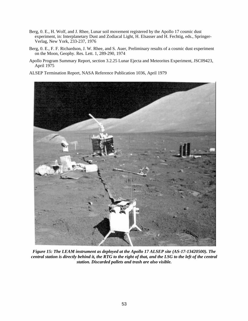
53
Berg, 0. E., H. Wolf, and J. Rhee, Lunar soil movement registered by the Apollo 17 cosmic dust experiment, in: Interplanetary Dust and Zodiacal Light, H. Elsasser and H. Fechtig, eds., Springer-Verlag, New York, 233-237, 1976
Berg, 0. E., F. F. Richardson, J. W. Rhee, and S. Auer, Preliminary results of a cosmic dust experiment on the Moon, Geophy. Res. Lett. 1, 289-290, 1974
Apollo Program Summary Report, section 3.2.25 Lunar Ejecta and Meteorites Experiment, JSC09423, April 1975
ALSEP Termination Report, NASA Reference Publication 1036, April 1979
Figure 15: The LEAM instrument as deployed at the Apollo 17 ALSEP site (AS-17-13420500). The
central station is directly behind it, the RTG to the right of that, and the LSG to the left of the central station. Discarded pallets and trash are also visible.

54
Experiment Operations During Apollo EVAs Acronym: None
PI/Engineer: See below
Apollo Flight No.: 11, 12, 14, 15, 16, 17
Weight: NA - See Lunar Geology - Tools
Manufacturer: NA
Experiment: Lunar Geology - General Information
Other Contacts: See below
Discipline: Lunar geosciences
Dimensions: NA
Apollo Experiment No.: S 059
Description/Purpose—The geological field work at the six Apollo sites was rigorously planned—some say too well orchestrated with no time for human thought, although this improved in the later “J” missions. The efforts behind the site selections and scientific objectives are beyond the scope of this database. A large body of documentation exists on this subject. Several tasks were repeated at many stations, and average times are available. The first task was generally a geological description of the area, which took ~5 minutes, including photography. Additional tasks are discussed below.
Unloading from the LM—NA
Transporting by foot or MET—The few tools used on A-11 were carried by hand. The EMU had attach points for sample bags. The A-12 crew had a small rack which held their tools. This was carried by hand. On A-14, the MET (see Miscellaneous Tools and Equipment) was used to transport the tool rack (the same as on A-12) and other equipment during longer traverses. On A-12 and most later flights a clip on a cable, which rolled up on a reel which was strapped to hoses on the front of the extravehicular mobility unit (EMU), was used to which several tools could be attached. This was known as a “yo-yo.”
Loading/unloading tools/experiments on LRV—On A-15, 16, & 17, the tools for the geological traverses were carried on a rack at the rear of the LRV. This rack could swing out to expose both sides of it. The sample return containers also attached to this rack so that the samples could be easily stowed. See Lunar Geology - Tools.
Site selection—Performed before launch by a site selection committee on the basis of scientific goals within operational (landing, orbital mechanics, etc.) constraints. Several stations were selected in advance for each traverse, with operations at each station carefully planned.
Deploying experiment—NA
Checkout of experiment—NA
Operation of experiment—NA
Repairs to experiment—NA
Recovery/takedown of experiment—NA
Stowing experiment for return—The samples were bagged and placed in the Apollo lunar sample return containers (ALSRC) for return.
Loading/unloading samples on LRV—Once the LRV was available, the sample collection bags were attached to a tool rack which was attached to the LRV. The bagged samples were placed in these for eventual placement into the “rock boxes” (ALSRC) and loading into the LM.
Loading of experiment/samples into the LM—A lunar equipment conveyor (LEC) was included on the early flights for loading the sample return boxes into the LM. It was more trouble than it was worth, and later crews merely carried the boxes up the ladder by hand.
Stowing of package once in the LM—The A-11 crew weighed the rock boxes outside, but the other crews carried them directly inside. After getting the samples into the LM and repressurizing, the boxes were weighed. The A-16 crew had to do some shuffling of rocks between boxes to keep them below

55
45 pounds each for weight and balance concerns. They also had to report the weights to Earth and wait to see if they could bring all the samples home. If not, the excess would have been tossed onto the surface before ascent. On A-12, this scale broke due to a loose nut.
A study indicated that, because of the temperature on the Moon's surface, lunar samples would cool the LM cabin when placed in the rock box inside the cabin, apparently because of the “dawn” sampling. An anecdote from John Young tells of his hand freezing to a rock which he had let cool in the shadow of the LM after he had brought it inside. After ~5 seconds it came loose. In the future, hot rocks could heat the area in which they were stored and be a bum hazard.
Sampling operations (soil, rocks)—The heart of the geology “experiment” was in the collection of samples while on traverses. The EVA on A-11 was limited to within 200 m of the LM. On A-12, walking traverses up to 500 m from the LM were performed. The Apollo 14 crew had the MET to carry their tools and went nearly 1.4 km from the LM. Once the LRV was available, traverses of up to 20 km, lasting up to 7.5 hours were possible, with stops at several geologically interesting stations. These were limited by the walk-back time to the LM (in the event of an LRV failure) vs. PLSS consumables.
A-11 had difficulty collecting the bulk sample. Difficulty scooping up the material without throwing it out as the scoop came free created some problem. It was almost impossible to collect a full scoop of material, and the task required double the planned time. The fact that the MESA was in shadow made the operation difficult, and they recommended a yaw maneuver just before touchdown to put this area into the sunlight.
During solo attempts to sample soil, an astronaut would have to hold the end of the loaded scoop in one hand, an open sample bag in the other, and then, with both arms extended, try to pour the soil into the bag. Some crew developed the ability to do solo sampling with relative ease by “walking” a hand down the handle of a shovel until it was close to the actual scoop, then bagging the sample closer to the chest. For two people, soil sampling was easier: one person manipulated the scoop, the other the bag. A-12 crew comments indicate that geological operations on the Moon are more difficult than on Earth because the color cues are not there. The lunar geologist has to look for texture, fracture, and luster, among other things, to aid in determining differences in rocks and minerals. Color differences were very slight. The samples were extensively photographed (usually) in-place before sampling, and the sampled area was photographed again post-sampling. A protocol was developed for documentation. The Preliminary Science Reports cross reference samples with photographs, sample numbers, and mission timeline.
The A-14 crew commented that they had a difficult time getting a single sample bag. When reaching for one, 2 or 3 would come loose. They would use one and the rest would fall to the ground. It was too difficult to recover them.
The A-15 crew emphasized their impression that their ability to identify rock types at the time of their collection seemed equal to their ability to do so during the many terrestrial field exercises of the training period. They felt basically unhampered (although somewhat slowed physically) by the bulky equipment. (Perhaps their impression-different from the A-12 crew-reflects a greater amount of pre-flight training-Ed.)
Documented samples, those with extensive photographic coverage, took ~3 minutes each on A-16. It was a two-person activity. Activities included: CDR - describe sample and place gnomon down-sun with pointer leg at sample and color chart at 45º to Sun; take stereo pair cross-sun at f/8, 1/250, 7 feet; collect sample; take “after” photo cross-sun at f/8, 1/250, 7 feet; describe area of sample; pick up gnomon; proceed to next sample; LMP - describe sample, take down-Sun photo at f/11, 1/250, 11 feet; prepare sample bag and report bag number; seal sample bag and place in collection bag; take locator photo using LRV in background cross-sun at f/8, 1/250, 15 feet. Special samples included deep drill cores, CSSD (Contact Soil Sampling Device), skim sample, and scoop sample. The A-16 crew had a lot of difficulty with their 20-bag dispensers falling off, which slowed down the sampling operations. Also, since each crewman had to place his samples into the bag which hung on the PLSS of the other crewman, their proximity to each other was necessarily close. Future sampling operations might benefit from allowing a crewman to place samples in a bag hanging on his own PLSS (requiring high flexibility in the suit) or perhaps from using a sack that can rest on the ground with a handle that can be reached for carrying like a shopping bag (per J. Young).

56
Trenching—Trenching was used to obtain sub-surface samples as well as to observe soil mechanics behavior. A deep trench (up to 60 cm) was dug on A-14. It took three minutes to dig a shallow trench on A-16. The soil mechanics studies added to this time, 10 minutes was allowed for such a trench on A-15 timelines. It was a two-person activity, but was done solo by the LMP (Irwin) due to timeline problems caused by the vise with the core tube sample. Planned activities included: LMP take locator photo with LRV in background, cross sun, f/8 1/250, 15 feet; use scoop to dig trench 3 - 8 inches deep 20º off sun-line; take “after” photo down-sun f/11, 1/250, 11 feet; CDR - select area to be sampled, place gnomon; take “after” photos, stereo pair cross-sun f/8, 1/250, 7 feet.
Raking—The rake was designed to provide a technique to obtain samples of small rocks, 1-to-5 cm, which would otherwise be very hard to obtain operationally. Because of the mobility of the suit, it was possible to operate it with one hand. On A-16, it took 8 minutes to get a rake sample with soil. It was a two-person activity. Activities included: CDR - select area for optimum rock distribution and place gnomon; describe area and relate to surrounding terrain; take cross-sun stereo pair f/8, 1/250, 7 feet; use rake to collect 1 kg of rocks (-1 sample bag full); get sample bag ready, report number, hold for LMP to fill; close sample bag containing fines (see below); seal and stow in sample collection bag (on LMP PLSS); take “after” shot, cross-sun, f/8, 1/250, 7 feet; LMP - remove rake and extension handle from LRV; hand rake to CDR; take “before” photo down-sun f/11, 1/250, 11 feet; make ready sample bag, report number; hold bag for CDR to fill; close and seal sample bag containing rocks (see above); stow in SCB (on CDR PLSS); collect 1 kg fines (1 bag full) from a pristine area; take locator shot, LRV or landmark in background, f/8, 1/250, 15 feet; stow rake on the LRV.
Core Tubes—Three generations of core tubes existed. Early tubes were sometimes hard to drive into the compact lunar regolith and did not always retain the core when removed. By A-15 new, thin-walled, larger-diameter core tubes were designed and worked well. On A-16, it took 5 minutes to get a single core tube, 11 minutes for a double core tube. A core sample vacuum container with single core took 9 minutes. It was a two-person activity. Activities included: CDR - place gnomon nearby; remove hammer from LMP PLSS tool carrier; take stereo pair cross-sun at f/8, 1/250, 7 feet; photograph tube and LRV f/8, 1/250, 15 feet (locator photo); obtain core tube cap from LMP PLSS and cap tube; remove core tube from extension handle; pull follower pin; get core tube tool and seat core follower against core; stow core in collection bag; stow core tube tool and hammer; pick up gnomon; proceed to next sample; LMP - remove core tube from CDR's sample bag; assemble core tube/extension handle; report number; hold core tube upright on surface and press into surface by hand; drive tube into surface, comment on difficulty; remove core from surface; assist CDR; get extension handle from CDR and install scoop; proceed to next sample. Double core tube procedures were similar except that the cap of the lower tube must be removed to mate the lower tube to the upper tube. The caps were replaced when the tubes were disassembled and the follower on each tube was seated with tool. The double core was rammed as a unit before the tubes were disassembled.
Drilling—A-15 was the first mission with the ALSD. Drilling the second hole for the heat flow probe on A-15 proved difficult. Because of the high torque levels on the chuck-stem interface, the drill chuck bound to the stems; in one case it was necessary to destroy the stem itself to remove it from the chuck. The drill stem was hard to remove from the hole. It was left in while the other tasks were completed. At the end of the second EVA it took both astronauts working at the limit of their combined strengths to pull up the drill stem. It was physically exhausting. Redesign for the last two flights was accomplished. The “treadle” was developed for removal of drill stems on the last two flights. Also, the core stems were redesigned to allow clearing the dense soil from the hole. The A-16 crew had little difficulty in drilling or extracting the deep core. Very little soil was lost during capping of the core stems. A typical timeline from A-15 shows ~26 minutes for drilling the deep core, taking photos, removing, separating, and capping the core segments.
Navigating/recognizing landmarks—On foot, navigation appears to have been the most difficult problem encountered during lunar surface activities (A-14 Mission Report). Unexpected terrain features, as compared to relief maps, were the source of navigational problems. The ridges and valleys had an average change in elevation of ~3 to 5 m. The landmarks that were clearly apparent on the maps were not

57
at all apparent on the surface. Even when the crewmen climbed to a ridge, the landmark often was not clearly in sight.
Later crews used the LRV, which had excellent navigation. A total of 5 hours was spent at traverse station stops on A-15, and the astronauts transmitted excellent descriptions of the lunar surface while in transit between stations. Also, much useful information was obtained from the TV camera on the LRV at 8 of the 12 stations.
Were there any hazards in the experiment, i.e. hazardous materials (explosive, radioactive, toxic), sharp objects, high voltages, massive/bulky objects, tripping hazards, temperatures?—The act of obtaining a sample without a tool can be very awkward, but falling in lunar gravity is so slow as to give plenty of time to act. Glove protectors were worn when working with the drill cores.
Was lighting a problem?—Generally not. Driving down-sun was difficult at first, but the crew adapted. The human eye could see into the shadowed areas very well. Operation in Earthshine seems very reasonable. Distance perception was difficult because the airless body did not provide the visual cue of haze.
Were the results visible to the crew?—NA
Would you recommend any design changes?—More time for investigation. Crew and PIs alike recommend that field geology be given less of a time line and more freedom to explore and think while investigating. Whether they would settle for fewer samples in trade is an open question.
Were any special tools required?—See Lunar Geology - Tools. See also Miscellaneous Tools and Equipment and Lunar Rover Vehicle - General Information.
Was the orientation of the experiment (i.e. horizontal/vertical) important? Difficult?—”The
absence of any natural vertical features, coupled with the poor definition of the horizon and the weak gravity...causes difficulty in identification of level areas”... (This) “is further complicated by the fact that when ... wearing a spacesuit, the center of mass ... is higher and farther back than normal...” (A-11 )
Was the experiment successful?—Yes.
Were there related experiments on other flights? Apollo? Other?—NA
Where was it stored during flight?—NA
Were there any problems photographing the experiment?—A protocol of documenting samples while on traverses was developed that eventually worked quite well. When pressed for time, however, this was sometimes skipped.
What pre-launch and cruise requirements were there? Power, thermal, late access, early recovery?—None reported.
What was different between training and actual EVA?—See other comments above. Trainers and PIs - Dave McKay/SN (early effort & general training for A-11 & 12)
Ted Foss (A-11 & 12, retired in early 70s) Gary Lofgren/SN4 (some on A-12, mostly 13 & 15) Bill Phinney/SN4 (branch chief for last 3) Fred Horz/SN4 (A-16) Don Morrison/SN4 (A-17) Mike McEwen (A-14, now retired)
Gordon A. Swann (PI for A-14 & 15, Center of Astrogeology, USGS, Flagstaff, retired) William R. Muehlberger (PI for A-16 & 17, Univ. of TX) John Dietrich (A-13, 14, now retired) E. M. Shoemaker (PI for A-12 - Calif. Inst. of Tech.) Jeff Warner (now at Chevron Research, La Haba, CA) Leon Silver (Cal. Tech. - general Apollo program advisor

58
and Ph.D. advisor for Mike Duke & Jack Schmitt) Uel Clanton - retired Jack Sevier (now at Lunar and Planetary Institute) Elbert King - early general training 1963-69. Professor of Geology at the University of Houston/Downtown Ray G. Zedekar, Lunar Surface Operations Office, now retired
What problems were due to the suit rather than the experiment?—Suit stiffness produced severe forearm fatigue. Any movement or positioning of a leg, arm, hand, or finger away from the “rest” configuration of the pressurized suit required constant muscle tension. Jack Schmitt described the problem as “like squeezing a tennis ball repetitively. Within a half hour or so, the forearm muscles were sufficiently fatigued to ache and you reached a much lower level of productivity using your hands than when you started. Eventually, by pacing yourself, you reached a constant level of forearm pain such that you could tolerate it and still do the job and not drop things and still apply sufficient grip to work, and that then went on for the rest of the EVA.”
There was also physical trauma that resulted from repeated reaching with the gloves. According to Schmitt, “as you reached in the suit and just got a little bit of scraping from the rubber bladder, it grabbed at your fingernail and, eventually, lifted the nail right off the quick. It was a problem we knew about before the mission, because others had experienced it. Knowing that, I wore some nylon liners. I still had the problem, but not as rapidly as Gene Cernan, who didn't wear any liners. Ultimately, all my nails were lifted off the quick. And that was just continuous, traumatic soreness which faded into the background and you didn't worry about it. I don't recall having rough or damaged fingertips, but I think Gene and a lot of the other guys did.”
Any experiences inside the LM of interest from the experiment/operations viewpoint?—No comments by crew.
References:
Preliminary Science Reports for all landed missions
“Moon Trip - A Personal Account of the Apollo Program and its Science,” Bert King, University of Houston, Houston, TX, 1989. Good general reference on training.
Apollo Scientific Experiments Data Handbook, JSC-09166, NASA TM X-58131, August 1974, in JSC History Office
Eric M. Jones, Working on the Moon: in: Proceedings of Space '90, ASCE, pp 1423 - 1432, 1990
Apollo 17 Final Lunar Surface Procedures, Vol. 1: Nominal Plans, MSC, 11/6/72
Apollo Program Summary Report, JSC-09423, April 1975
Personal communication with J. Young, 1 April 1993
Apollo 14 Technical Crew Debriefing, 17 February 1971, in the JSC History Office
Don E. Wilhelms, “To a Rocky Moon, A Geologist's History of Lunar Exploration,” University of Arizona Press, Tucson, 1993
The personal files of Shoemaker and Masursky re lunar traverse planning and training are at the National Archives branch at Laguna Niguel, CA. Personal communication from Dr. Joseph N. Tatarewicz to Thomas Sullivan.
A great deal more information is available concerning geology training in the JSC History Office from the personal files of R. Parker.

59
Figure 16: Apollo 12 astronaut with the tongs used to grab small rocks without bending over (AS-12-
48-7148). See also figure 11 for the scoop.

60
Experiment Operations During Apollo EVAs Acronym: Several for individual tools
PI/Engineer: See Lunar Geology - General Information
Apollo Flight No.: 11, 12, 14, 15, 16, 17
Weight: See reference catalog & below
Manufacturer: JSC, unless noted
Experiment: Lunar Geology - Tools Also see - Lunar Geology - General and Soil Mechanics
Other Contacts: Solar System Exploration Div.
Discipline: Lunar geosciences
Dimensions: See reference catalog
Apollo Experiment No.: S 059 and S 200
Description/Purpose—The tools used in geological field work are well documented in various photos, reports, and the reference catalog below.
Unloading from the LM—No problems reported removing tools from bays within LM.
Transporting by foot or MET—A hand tool carrier was used to carry the tools on A-12. It was also carried, with its tools, on the MET for A-14.
Loading/unloading tools/experiments on LRV—The tools could fit in a rack on the back of the LRV. See reference catalog.
Site selection—NA
Deploying experiment—NA
Checkout of experiment—NA
Operation of experiment—Operation of the tools was, for the most part, nominal. The hammer became very hard to grip against the pressurized glove, however. A larger diameter handle would have alleviated the problem. The other tools did not seen to present this problem since they were not used as frequently nor for as long a time.
Repairs to experiment—A vise on the A-15 LRV, which was to be used to separate drill core stems segments, was designed incorrectly on Earth. Its jaws, similar to a pipe wrench, could only be used to tighten the cores, not loosen them. The Earth trainer had been installed backwards and so worked properly, but the flight tool was installed as per the drawings, and cost Scott and Irwin both time and aggravation.
Recovery/takedown of experiment—NA
Stowing experiment for return—Tools were left at the landing site. Two ALSRCs per flight were used to return the sample bags. These were to maintain the samples in lunar vacuum for their return, but 4 of the 12 had a substantial leak. On A-15, it was very hard to close at least one of these containers because a bag was caught in the rear hinge. This caused problems in stowing the SRC in the LM, the pins would not engage, and they finally taped it in place for ascent. Extra sample bags were exposed to the cabin and Earth's atmosphere.
Loading/unloading samples on LRV—Sample collection bags could be attached to the tool carrier rack at the back of the LRV.
Loading of experiment/samples into the LM—See Geology - General Information.
Stowing of package once in the LM—NA. The tools were left on the Moon.
Sampling operations (soil, rocks)—The scoop was used to sample soil. Tongs were available to grab larger rock samples. Very large boulders were sampled using the chisel end of the hammer to break off a piece.
Trenching—The long handle scoop was used for digging trenches.

61
Raking—The rake was developed as a way to obtain many rock samples of > 1 cm easily.
Drilling—The ALSD, manufactured by Martin Marietta, was considered by some as part of the ALSEP package, although it was also used to obtain deep core samples. It had a rotary-percussive action. It was 13.4 kg, total, and 57.7 x 24.4 x 17.8 cm, not including the drill string and caps. It took 5 to 15 minutes to drill a hole, depending on the material. The core stems came in sections. After the first two sections were assembled and drilled in so that ~15 cm remained above the surface, the drill was removed from the core with a wrench and the second pair of core stems were assembled and attached. Then the drill was attached to this new section and the drilling continued until the third and fourth pairs had to be attached in like fashion. Drilling the second hole for the heat flow probe on A-15 proved difficult. Because of the high torque levels on the chuck-stem interface, the drill chuck bound to the stems; in one case it was necessary to destroy the stem itself to remove it from the chuck. For the A-15 deep core, the drill stem was hard to remove from the hole. It was left in while the other tasks were completed. At the end of the second EVA it took both astronauts working at the limit of their combined strengths to pull up the drill stem. It was physically exhausting. Its removal took an extra 15 minutes of EVA time and caused a severe shoulder sprain in Scott. This is why the jack was developed for removal of drill stems on the last two flights. Also, the core stems were redesigned to allow clearing the dense soil from the hole by operation at constant depth to bring soil to the surface. The A-16 crew had little difficulty in drilling or extracting the deep core. Very little soil was lost during capping of the core stems.
A rack was supplied which held the bore stems for the HFE off the ground and made them easy for a suited crewman to reach. The core stems for the deep core were stored on the hand tool carrier on the back of the LRV.
Coring—The core tubes were redesigned twice from the early missions to make them easier to drive into the soil. The bevel in the early design compacted the soil and made it difficult to drive into the soil. See tool catalog. The hammer used to pound the core tubes had a small striking area and its side was used to drive the tubes because of the inaccuracy of arm motion in the EMU.
Navigating/recognizing landmarks—See LRV.
Were there any hazards in the experiment, i.e. hazardous materials (explosive, radioactive, toxic), sharp objects, high voltages, massive/bulky objects, tripping hazards, temperatures?—The tools could be considered hazardous in a number of ways. The drill was capable of high torque and could have damaged any cords or hoses that got entangled in it. Glove protectors were available while operating it, but these restrained hand movements even further. The hammer had a “chisel” end which could have damaged a suit, and any pieces of rock that flew off during sampling may have scratched a visor. The thin metallic coating on the hammer fractured and flew off during normal hammering operations on A-12.
Was lighting a problem?—Generally not. Some samples were to be taken from permanently shadowed areas, however.
Were the results visible to the crew?—Yes.
Would you recommend any design changes?—Changes were made as the missions progressed and experience developed. Extension handles got longer. The LRV sampler was developed for A-17 to get samples from areas between stations.
Were any special tools required?—The ALHTs were considered by some as part of the ALSEP package, but they were mostly used in the geological field work. The materials from which the tools were made were limited to special choices so as not to contaminate the samples. These included
Teflon, stainless steel, and aluminum. See the reference catalog. Total weights of geological tools per mission were as follows: A-11, 22.9 kg; A-12, 29.2 kg; A-14, 34.1 kg; A-15, 50.3 kg; A-16, 53.0 kg; A-17, 45.7 kg.
Was the orientation of the experiment (i.e. horizontal/vertical) important? Difficult?—NA
Was the experiment successful?—See Geology - General Information.

62
Were there related experiments on other flights? Apollo? Other?—Samples of the Moon were also obtained by three robotic Lunakhod flights.
Where was it stored during flight?—On some flights, the tools were packed with the ALSEP.
Were there any problems photographing the experiment?—A protocol of photodocumentation was developed to document samples. Tools were often used for scale.
What pre-launch and cruise requirements were there? Power, thermal, late access, early recovery?—None.
What was different between training and actual EVA?—-Scott (A-15) commented that it seemed more difficult to screw the sections of the drill stems together during EVA than it was in training. Charles Duke (A-16) and Cernan (A-17) concurred, and suggested a small workbench would have helped.
What problems were due to the suit rather than the experiment?—No comments by crew.
Any experiences inside the LM of interest from the experiment/operations viewpoint?—No.
References: Catalog of Apollo Lunar Surface Geological Sampling Tools and Containers, JSC-23454 Apollo Lunar Surface Experiments Package - Apollo 17 ALSEP (Array E) Familiarization Course
handout for class of 1 September 1972, in JSC History Office Apollo Scientific Experiments Data Handbook, JSC-09166, NASA TM X-58131, August 1974, in JSC
History Office Eric M. Jones, Working on the Moon: in: Proceedings of Space '90, ASCE, p 1423 - 1432, 1990 Apollo Program Summary Report, JSC-09423, section 3.2.7, Geology and Soil Mechanics Equipment,
April 1975 Apollo 15 Technical Crew Debriefing, 14 August 1971, in JSC History Office
Figure 17: The rake was developed to obtain a greater number of small rock samples than could be
obtained using the tongs (AS-17-134-20425). Note the sample bags attached to the PLSS of the crewman. Since he could not reach his own sample bags, each crewman had to place samples in the
other person's sample bags. See also figure 37 for the rake and scoop mounted on the pallet at the rear of the LRV.

63
Figure 18: This view from Apollo 12 shows the hand tool carrier and a core tube, attached to the
extension handle, being emplaced into the soil (AS-12-49-7243). Numbered sample bags are held in the hand tool carrier. Additional core tubes are visible in the carrier. See also figure 30 for a view of
the gnomon which provided a reference to vertical, scale, Sun orientation, slope, and gray scale.

64
Experiment Operations During Apollo EVAs Acronym: LNPE (NFE)
PI/Engineer: D. S. Burnett/Califomia Institute of Technology
Apollo Flight No.: 17
Weight: 2.27 kg, total; only 1.86 kg probe and 0.4 kg container returned
Manufacturer: Calif. Inst. of Tech.
Experiment: Lunar Neutron Probe Experiment (a.k.a. Neutron Flux Experiment
Other Contacts: Dorothy S. Woolum, C. A Bauman/Cal. Tech.
Discipline: Lunar dust, radiation, attenuation by regolith
Dimensions: 2.35 m long, deployed; 1.23 m long, stowed; 2 cm dia. nom., 4.5 cm dia. at top
Apollo Experiment No.: S 229
Description/Purpose—Time-integrated fluxes of thermal neutrons as a function of depth in the regolith were measured using targets of boron-10 and uranium-235 placed at intervals along a 2-m rod that was inserted into the hole left by the deep drill core. Cellulose triacetate plastic detectors were used in conjunction with the B-10 targets, and mica detectors were used in conjunction with the U-235 targets. Some information on the energy distribution of the equilibrium flux was also obtained by including two cadmium absorbers and three KBr capsules at different depths on the probe. Temperature indicators were included at four points along the length of the probe to record its thermal history. This information has geological relevance to the speed of regolith turnover. It is also important for the understanding of radiation protection required for longer human occupancy of the Moon. For stowage, the probe was fabricated in two 1-m-long sections.
Unloading from the LM—Nominal, from LM MESA. It was stored inside its thermal bag.
Transporting by foot or MET—NA
Loading/unloading tools/experiments on LRV—At beginning of EVA 1. To prevent overheating, the two sections of the LNPE were kept in a thermal bag during the EVA before actual deployment.
Site selection—The deep drill core stem sample was acquired at a site ~38 m north of the ALSEP central station and the RTG. The site was in a shallow depression and behind a meter-sized rock, which should have provided additional shielding from the RTG neutrons.
Deploying experiment—Deployed during EVA 1 on A-17. The probe was inserted into the hole left behind after obtaining the deep drill core, and recovered at the very end of EVA 3, after 49 hours of exposure. After deployment of ALSEP and recovery of the deep core, the two LNPE sections were removed from the thermal bags, activated, coupled, and emplaced in the hole. Nominal insertion by hand was made after first passing the probe through the hole in the treadle used for recovering the deep core because, in retrieving the core, the top of the hole had been widened; thus, the possibility existed that the probe would drop too far into the hole to be retrieved. Backup procedures for emplacing the probe by hammering or with the ALSD existed. To prevent overheating, the top of the probe protruding above the surface was covered with the thermal bag during exposure.
Before insertion into the hole, the probe was activated by twisting the unit, thus aligning the neutron targets with their particle track detectors. Deactivation was accomplished by again twisting the unit to move the particle track detectors away from the neutron capture targets.
Each segment of the probe could be activated separately. The upper section was activated by depressing a bar on the large handle at the upper end and rotating 180º. The lower section was activated by removing the dust cap at its upper end and using it as a tool to rotate the central rod, which was spring-loaded to snap into one of two configurations 180º apart. The two sections could then be coupled for deployment by simply screwing them together.

65
This activation/deactivation sequence was necessary to prevent the accumulation of background events from neutrons produced by cosmic ray interactions in the spacecraft and by the plutonium238 power source for the ALSEP package.
Checkout of experiment—-Correct activation was verified after return to Earth by inspection of alpha particle tracks from the U-238 sources.
Operation of experiment—Activated, inserted, retrieved, and deactivated probe without difficulty. Otherwise passive. It had a total activated exposure period of 49 hours.
Repairs to experiment—NA
Recovery/takedown of experiment—Recovered probe on EVA 3. The core jacking mechanism (treadle) was used to remove it from the hole. The two probe segments were separated by unscrewing for storage and then deactivated by twisting within a minute or two after withdrawal from the hole. The experiment was placed in the shade of the LM within ~3 minutes.
Stowing experiment for return—The probe was placed in a return container on top of a core stem return container in storage area A5 of the LM.
Loading/unloading samples on LRV—NA
Loading of experiment/samples into the LM—No comments by crew.
Stowing of package once in the LM—No comments by crew.
Sampling operations (soil, rocks)—NA
Trenching—NA
Raking—NA
Drilling—Drilling the hole for the deep core presented some problems during the extraction, but all sections of the core were obtained, and the hole did not collapse, therefore allowing the insertion of the probe. The treadle was left in place to support the probe and not allow it to fall too far into the hole. Without this treadle to mark the location, the hole would have been very hard to find again after walking away to get the probe due to the shadows from random bumps on the ground.
Navigating/recognizing landmarks—NA
Were there any hazards in the experiment, i.e. hazardous materials (explosive, radioactive, toxic), sharp objects, high voltages, massive/bulky objects, tripping hazards, temperatures?—There was U-235 as a neutron absorber target which would fission and release more neutrons, which was what was actually detected by the mica. There were also U-238 point sources which verified correct activation and deactivation.
Was lighting a problem?—No.
Were the results visible to the crew?—No.
Would you recommend any design changes?—None made by crew.
Were any special tools required?—ALSD required to provide hole. The dust cap of the lower segment served as a tool for its activation.
Was the orientation of the experiment (i.e. horizontal/vertical) important? Difficult?—Needed to be subsurface. Hole should be vertical so that depth of regolith is known.
Was the experiment successful?—Yes.
Were there related experiments on other flights? Apollo? Other?—Thermal neutrons were to be measured as part of the cosmic ray/regolith interaction on the CRD (S 152) on A-16. Analysis of the returned lunar samples from all the flights used thermal neutron capture to explain certain isotopic abundances.

66
Where was it stored during flight?—LM MESA in Quad IV.
Were there any problems photographing the experiment?—No.
What pre-launch and cruise requirements were there? Power, thermal, late access, early recovery?—Did not want the probes to get above 333 K.
What was different between training and actual EVA?—No comments by crew.
What problems were due to the suit rather than the experiment?—No comments by crew.
Any experiences inside the LM of interest from the experiment/operations viewpoint?—No comments by crew.
References: A-17 Preliminary Science Report Apollo Scientific Experiments Data Handbook, JSC-09166, NASA TM X-58131, August 1974, in JSC
History Office Apollo Program Summary Report, section 3.2.18, Lunar Neutron Probe Experiment, JSC-09423, April
1975 Apollo 17 Final Lunar Surface Procedures, Vol. 1: Nominal Plans, MSC, 11/6/72 Apollo Stowage List - Apollo 17, MSC, 12 December 1972
Figure 19. The assembled flight unit of the lunar neutron probe. The upper section, with the probe
handle at the top, is on the right. The lower section with its removable dust cap is on the left. Coupling of the two sections was accomplished by screwing the lower and upper units together after removing
the dust cap. Each section was approximately 1 m long.

67
Experiment Operations During Apollo EVAs Acronym: LRV
PI/Engineer: NA
Apollo Flight No.: 15, 16, 17
Weight: 200 kg; Could carry 490 kg of payload, including 2 astronauts, PLSSs, tools, equip- ment, & 27 kg of lunar samples each trip
Manufacturer: Boeing
Experiment: Lunar Rover Vehicle
Other Contacts:
Discipline: Rovers
Dimensions: 3.1 m long, 1.83 m wide, 1.14 m high, 2.3 m wheelbase
Apollo Experiment No.: NA
Description/Purpose—This rover was used to extend the range of the astronauts so that a greater variety of terrain could be visited. It had a 90-inch wheelbase, was 81 inches wide, and weighed 455 lbs empty. Its gross operational weight was 1535 pounds with crew, equipment, and payload. Power was supplied by two 36V silver zinc batteries with sufficient power for a range of 65 km at speeds up to 17 km/h, although a top speed of 22 km/h was obtained on A-16. If either battery failed the other could carry the entire load. Four separate motors, one at each wheel, drove the vehicle, but any wheel could be cut out to “free-wheel” if its drive mechanism developed problems. All the driving functions were controlled by a T-handle mounted between the seats. The vehicle had four-wheel, double Ackerman steering. It could climb over obstacles 30 cm high, climb and descend slopes of 25 degrees, and park on slopes of up to 35 degrees. Speeds of 10 kph were attained within three vehicle lengths. Going in reverse was possible with one dismounted crewmember confirming the general condition of the surface to be covered, but this was not often done.
Unloading from the LM—For deployment, some thermal blankets needed to be removed from the LM and one of the crew had to climb the ladder to pull a “D-ring,” then descend the ladder. Both crewmembers then had to apply a steady pull on deploy cables and tapes until the wheels were on the ground. After it was on the ground, the crew actually picked it up and turned it 90º. The fenders, seats, seat belts, and console then had to be deployed on it. On A-15 there were some problems with deployment and checkout, but they were quickly solved. It took 26.5 minutes rather than the 17 planned. A-16 also had to lock some pins to complete deployment.
On A-15, during the first traverse the front steering did not work, but the rear steering allowed them to complete the EVA without problems. While going downhill with any speed and the front wheels locked in the straight ahead position they did a “180” turn when they tried to maneuver. On the second and third EVA, the front steering became operable. This rover covered 27.9 km by its odometer, corresponding to a map distance of ~25.3 km. Its average speed was 9.6 km/hr, and speeds up to 12 km/hr were attained over level terrain. The A-16 LRV covered 27 km. The A-17 LRV covered ~35 km. The longest traverse was on A-17, where it covered 19.5 km during EVA 2.
Transporting by foot or MET—NA
Loading/unloading tools/experiments on LRV—A loading and unloading time was allotted for putting tools and equipment on the LRV. Checklists existed for these procedures.
Site selection—An operational constraint on the use of the LRV was that the astronauts must be able to walk back to the LM if the LRV were to fail at any time during the EVA. Thus, the traverses were limited in the distance they could go at the start and at any time later in the EVA. Therefore, they went to the furthest point away from the LM and worked their way back to it so that, as the life support consumables were depleted, their remaining walk back distance was equally diminished. A Buddy Secondary Life Support System was carried on the LRV to share cooling water from one PLSS to the other if one failed.
Deploying experiment—See above.

68
Checkout of experiment—The CDR took the LRV for a test spin around the LM to the vicinity of the MESA after deployment. The tools and other equipment needed on the EVA were loaded from the MESA and Quad III onto the LRV.
Operation of experiment—On A-15, the seat belts were difficult to fasten. Pre-launch adjustments did not properly account for the reduced gravity in combination with the pressurized suits, and the belts were too short. This was corrected for A-16 & 17 by measuring the settings on the KC-135. Detailed procedures for offloading, setup, power-up, navigation alignment, stopping at traverse sites, navigation updates, malfunctions, and closeouts are provided in the Final Surface Procedures documents.
Repairs to experiment—The rear fender extension on the A-16 LRV was lost during EVA 2 at station 8 when Young bumped into it while going to assist Duke. The dust thrown up from the wheel covered the crew, the console, and the communications equipment. High battery temperatures and resulting high power consumption ensued. No repair attempt was mentioned. The fender extension on the A-17 LRV broke when accidentally bumped by the CDR with a hammer handle. The crew taped the extension back in place, but because of the dusty surfaces, the tape did not adhere and the extension was lost after about 1 hour of driving, allowing the astronauts to be covered with dust. For the second EVA, a replacement “fender” was made with some EVA maps, duct tape, and a pair of clamps from inside the LM - nominally used for the moveable overhead light. This repair was later undone so that the clamps could be brought back inside for launch. The maps were brought back and are now on display at the National Air and Space Museum. The abrasion from the dust is evident on some portions of the makeshift fender.
Recovery/takedown of experiment—NA
Stowing experiment for return—NA
Loading/unloading samples on LRV—Sample containers and tools were attached at the rear of the LRV.
Loading of experiment/samples into the LM—NA
Stowing of package once in the LM—NA
Sampling operations (soil, rocks)—Some of the tools and SCBs (see Lunar Geology - Tools) attached to a tool carrier which attached to the back of the LRV to aid in sampling. Also, on A-17 only, there was a new sampling device (LRV soil sampler, see Geology - Tools) that allowed for the collection of samples while seated in the LRV. Thus, A-17 is the only LRV-aided mission with samples collected between stations.
Trenching—NA
Raking—The rake was carried in the rear-mounted tool carrier.
Drilling—NA
Navigating/recognizing landmarks—The requirements for the rover were that it display vehicle heading, bearing to the last point of initialization (usually the LM), speed (km/h), total distance traveled (km), and distance to the LM (km). It did not need to have pitch, roll, X and Y coordinates, or time, although a pitch indicator was present on all LRVs. At the start of a traverse the astronauts oriented the system's navigational gyroscope with reference to the Sun. It took nearly two minutes for the gyro to reach operating speed. The navigation system was said to be accurate to within 100 m of range. At the end of EVA 1 on A-15 when the crew returned to the LM they estimated its bearing at 15º, but the navigation system said it was at 34º, indicating some drift, but the range accuracy may still have been correct.
On A-15, dust was kicked up on acceleration of the LRV and when crossing the rims of soft craters. Little of the dust impacted on the LRV itself or on the crew, and it did not cause any problems with visibility or operation of the vehicle, although frequent cleaning of the lunar communications relay unit (LCRU) was required to prevent overheating of the TV circuits. No dust accumulation was noted in the wire wheels, but a thin layer of dust eventually covered most of the vehicle.

69
Minor operational problems were caused by thin layers of dust on the camera lenses and dials, gnomon color chart, navigation maps, and LCRU mirror. The dust was easily brushed off, but the dust was so prevalent that, during part of the mission the crew reported that, to set the lens, dust had to be wiped from the camera settings every time they took a picture.
The A-16 crew commented that the map holder on the LRV was worthless and got in the way. Instead, they wedged a map in between the camera and a staff. The maps did not reflect the topography very well. They also lost their navigation unit during the return of the second EVA due to inadvertently hitting a protected switch. They got it back for the third EVA.
One experiment, the surface electrical properties (SEP) experiment, recorded navigational information from the LRV onto a tape recorder for analysis of its data. The navigation unit of the LRV was also used to orient the transmitting antennas of the SEP on A-17 and to align the geophones of the ASE on A-16 by leaving tracks along the proper direction.
On A-17, the crew got 7370 meters away from the LM on EVA 2, the farthest of any crew. The CDR commented that, because of the inability to travel on a straight line for very long periods of time, he primarily did not navigate on a heading. Rather, he navigated to points defined by bearing and range, those points being the planned jogs in the traverse, or for samples, or LSPE charge deploys, or stations. It worked well, and was why they never followed their tracks back to anywhere.
Because of the low pressure exerted by the wheels on the soil, the average depth of the tracks was only ~1¼ cm, varying from near 0 to 5. On one occasion, because of its light weight, the LRV had a tendency to slide sideways down a rather steep slope as soon as the A-15 crew stepped off the vehicle. Maneuvering the vehicle on slopes did not present any serious problems. It was reported that the vehicle could be controlled more easily upslope than downslope; and, when the vehicle was traversing along slope contours, the wheels on the downslope side tended to displace to soil laterally and to sink more than the wheels on the upslope side. On A-17, the bouncing from craters at times caused a feeling of nearly overturning while traveling cross-slope, and the crew did reduce their speed somewhat as a result.
On A-16, the crew climbed slopes of up to 18º in the LRV and thought that it was approaching its limit of slope-climbing ability. Tests on Earth predicted a maximum of 19º to 23º. In general, they had no serious operational problems on slopes.
Were there any hazards in the experiment, i.e., hazardous materials (explosive, radioactive, toxic), sharp objects, high voltages, massive/bulky objects, tripping hazards, temperatures?—Dust kicked up by the wheels covered the astronauts, especially when the fender broke off. Both crewmen on A-17 commented that the restraint system on the LRV was inadequate, especially on slopes.
Was lighting a problem?—Driving down-sun or into the Sun was difficult due to visibility problems. The A-16 crew could go no faster than 4 or 5 kph and still ran right over some craters because they could not see them until they were on top of them. Boulders could be seen and avoided.
Were the results visible to the crew?—NA
Would you recommend any design changes?—The seat belt design was changed for the later flights to account for the lower g. The restraint system design could be improved further, especially for driving on slopes. The A-15 crew recommended a bar, such as in a kiddie ride, which would lock in place to restrain the crew, or push out of the way easily. This had been considered but not accepted due to the weight penalty vs. seat belts. The time advantage vs. working the seat belts might be worth it, however. For A-17, fender extension stops were added based on the loss of the fender extension on A-16. The sighting device on the antenna could be improved by opening up the light passage through it to improve the visibility of Earth.
Were any special tools required?—No
Was the orientation of the experiment (i.e. horizontal/vertical) important? Difficult?—Driving on slopes left the down-slope crew member feeling precarious. The LCRU, a high-gain antenna mounted on the LRV, had to be oriented at each station for television transmission to Earth. TV was cut off while moving, but voice communication was maintained over the low-gain antenna. The low-gain antenna for A-17 had to be aimed at Earth due to the location of this landing site. This was done by “dialing in” a reciprocal heading for antenna aiming from that being driven. The other sights were more sub-Earth and

70
could use a vertically pointing antenna. Orientation of the high-gain antenna was accomplished with an optical sighting device, but this presented a very dim image of Earth which was hampered by the helmet visor. The use of signal strength, as indicated on the AGC control meter, was an acceptable backup alignment technique.
Was the experiment successful?—The LRV worked very well and extended the operable range of the crew on EVA.
Were there related experiments on other flights? Apollo? Other?—NA
Where was it stored during flight?—LM quadrant 1.
Were there any problems photographing the experiment?—The television camera on the LRV was operable from Earth, allowing the ground to observe a “station” in panorama while the astronauts were doing field work. The camera which was to film the “grand prix” on EVA 2 of A-15 did not operate because the film magazine was faulty.
What pre-launch and cruise requirements were there? Power, thermal, late access, early recovery?—None reported.
What was different between training and actual EVA?—The Earth trainer had rubber tires and could support its own weight in 1 g. The flight article would have collapsed in 1 g if the crew sat on it. Since the handling characteristics of the LRV could not be fully tested on Earth, a “grand prix” test was performed by the CDR on A-15 & 16. The trainer provided adequate simulation, the major difference was having to pay constant attention to the lunar terrain in order to have adequate warning of obstacles, especially in adverse lighting situations. Braking required ~2 x the 1 g distance. Steering was not as responsive between 8 - 10 kph with hard-over inputs.
What problems were due to the suit rather than the experiment?—The suit used for the last three flights was able to bend at the waist, allowing the astronaut to sit on the LRV. This also allowed them to kneel, which assisted some experiment deployment and sample collection.
Any experiences inside the LM of interest from the experiment/operations viewpoint?—NA
References:
Mission Reports for Apollo 15, 16, and 17
Final Lunar Surface Procedures - Apollo 16, March 16, 1972, MSC
Final Lunar Surface Procedures - Apollo 17, November 6, 1972, MSC
Apollo Program Summary Report, section 4.8.2, Lunar Roving Vehicle, JSC-09423, April 1975
Apollo 15 Technical Crew Debriefing, 14 August 1971, in JSC History Office
Apollo 16 Technical Crew Debriefing, 5 May 1972, in JSC History Office
Apollo 17 Technical Crew Debriefing, 4 January 1973, in JSC History Office
“Lunar Sourcebook - A User's Guide to the Moon,” G. Heiken, D. Vaniman, and B. French, Eds., Cambridge University Press, Cambridge, 1991
Personal communication from John Young, 1 April 1993
Personal communication from Jack Sevier, 18 May 1993
Personal communication from Eric Jones, 3 August 1993

71
Figure 20: This view of the LRV from Apollo 16 shows the crewman at the front and the tool carrier at the left (AS-16-108-17729). See also figure 11 and figure 37 for other views of the LRV. Compare the
antenna on the LRV to the erectable antenna in figure 25.

72
Experiment Operations During Apollo EVAs Acronym: LSPE
PI/Engineer: Robert L. Kovack Stanford University
Apollo Flight No.: 17
Weight: 25.1 kg, total; 7.1 kg geophones,
Manufacturer: Bendix
Experiment: Lunar Seismic Profiling Experiment
Other Contacts: Joel S. Watkins/UT-Galveston Pradeep Talwani/Stanford
Discipline: Lunar seismology
Dimensions: Several packages - see reference 17.6 kg explosives
Apollo Experiment No.: S 203
Description/Purpose—This is an extension of the ASE carried on A-14 and 16. The data were planned to determine the internal characteristics of the lunar crust to a depth of several kilometers. Eight explosive charges (containing from 57 to 2722 g of high explosive) were deployed at distances between 100 m and 3.5 km from an array of four identical geophones. These charges were later detonated by a timer after LM ascent stage lift-off, and seismic measurements were obtained. The electronics for the experiment were one of the ALSEP packages. A whip antenna was deployed near the HFE which sent the signals to these charges. For stability, the antenna was mounted to the subpallet to which the HFE had been mounted for transport.
Unloading from the LM—As part of the ALSEP packages.
Transporting by foot or MET—The geophones were carried as part of the ALSEP.
Loading/unloading tools/experiments on LRV—The explosive charges were carried on the traverses for deployment at distant sites-see figure 37 for placement on the LRV. No particular hazards or problems were encountered.
Site selection—The geophone array was part of the ALSEP on A-17. Explosive charges were placed at distant locations while on field geology traverses. Charges deployed within line-of-site of the ALSEP were deployed in shallow depressions.
Deploying experiment—Operations were spread out over the three EVAs. The ALSEP electronics module containing the four geophones was deployed on EVA 1 without difficulty. The timeline allotted 29 minutes to deploy and photograph them. Two explosive packages were also deployed on EVA 1, three on EVA 2, and three on EVA 3. See “hazards” for arming sequence of the explosive package. The packages needed to be in the Sun to ensure temperatures above 5ºC before activation. Also, each explosive package had to have a telescoping antenna pulled out.
Checkout of experiment—From Earth.
Operation of experiment—From JSC via the ALSEP command system. The explosive charges were set off after the crew left. Also, the crash of the ascent stage of the LM was recorded. High and low scan rates could be selected.
Repairs to experiment—NA
Recovery/takedown of experiment—NA
Stowing experiment for return—NA
Loading/unloading samples on LRV—There were temperature requirements on the timers in the explosive packages that constrained LRV operations in the shade.
Loading of experiment/samples into the LM—NA
Stowing of package once in the LM—NA
Sampling operations (soil, rocks)—NA

73
Trenching—NA
Raking—NA
Drilling—NA
Navigating/recognizing landmarks—NA
Were there any hazards in the experiment, i.e., hazardous materials (explosive, radioactive, toxic), sharp objects, high voltages, massive/bulky objects, tripping hazards, temperatures?—Explosive charges were used for active sounding. These were deployed by the crew while on traverses, but not activated until after departure. All eight were fired. An explosive package was activated by removing three pull pins. Removal of the first pin activated the SAFE/ARM slide timer, which was preset at ~90 hours (each one varied slightly). Removal of the second pull pin released the SAFE/ ARM slide from its constrained SAFE position. Removal of the third pin removed a constraint on the firing pin and activated the thermal battery timer. The LSPE transmitter, which was located on the ALSEP central station, transmitted a repetitive pulsed carrier signal. A series of three pulses properly spaced in time was required to elicit a FIRE signal from the signal processor within the explosive package and to detonate the explosives train. The thermal battery, activated by the timer, had a minimum life of two minutes, ensuring that at least one firing pulse set was received while the explosive package was energized electrically. One of the explosions was seen via TV by using the camera of the LRV after departure of the crew.
There was concern late in the A-17 mission planning when someone raised the possibility that the larger charges could conceivably throw debris to altitudes where the command/service module (CSM) was still gathering orbital data two days later. Although it was a remote possibility, the idea of “shooting down” the last mission after it had successfully landed and returned to orbit did not sit well with NASA Headquarters. After a hastily convened group of explosive (Bureau of Mines, NRL, and others) and cratering/impact experts met, it was calculated that the risk was in the range of 10-5 to 10-6, which was good enough to allow the experiment to proceed.
Was lighting a problem?—No.
Were the results visible to the crew?—No.
Would you recommend any design changes?—No comments by crew.
Were any special tools required?—No, although the LRV was used to deploy the charges.
Was the orientation of the experiment (i.e. horizontal/vertical) important? Difficult?—The arrangement of the geophones was planned to gather seismic signals.
Was the experiment successful?—Yes
Were there related experiments on other flights?—See S 033, ASE on A-14 and A-16. See also S 031, PSEP.
Where was it stored during flight?—Explosive packages stored in Quad III in two groups of four. The rest of the unit was in Quad IV on the MESA.
Were there any problems photographing the experiment?—No.
What pre-launch and cruise requirements were there? Power, thermal, late access, early recovery?—None reported.
What was different between training and actual EVA?—No comments by crew.
What problems were due to the suit rather than the experiment?—No comments by crew.
Any experiences inside the LM of interest from the experiment/operations viewpoint?—No comments by crew.

74
References:
A-17 Preliminary Science Report
Apollo 17 Mission Report
Apollo 17 Final Lunar Surface Procedures, Vol. 1: Nominal Plans, MSC, 11/6/72
Apollo Lunar Surface Experiments Package - Apollo 17 ALSEP (Array E) Familiarization Course handout for class of 1 September 1972, in JSC History Office
Apollo Scientific Experiments Data Handbook, JSC-09166, NASA TM X-58131, August 1974, in JSC History Office
Apollo Program Summary Report, section 3.2.11, Lunar Seismic Profiling Experiment, JSC-09423, April 1975
ALSEP Array E Critical Design Review Presentation Material, NASA/MSC - Bendix Aerospace Systems Division, NAS9-5829, 14 - 18 June 1971, in JSC History Office
Personal communication, Jack Sevier to Tom Sullivan, 18 May 1993
Figure 21: Explosive package used for the LSPE. Figure 37 shows four of the charges mounted at the
rear of the LRV while on a traverse.

75
Experiment Operations During Apollo EVAs Acronym: LSM
PI/Engineer: Palmer Dyal Ames Research Center
Apollo Flight No.: 12, 15, 16
Weight: 8.6 kg
Manufacturer: Naval Ordinance Lab & NASA Ames Research Center; Philco - Ford
Experiment: Lunar Surface Magnetometer
Other Contacts: Joel Charles P. Sonett/Lunar & Planetary Lab/U of AZ
Discipline: Lunar magnetometry
Dimensions: 25 x 28 x 63 cm, stowed
Apollo Experiment No.: S 034
Description/Purpose—The purpose of the magnetometer was to measure the magnetic field on the lunar surface and to determine from these measurements some of the deep-interior electrical properties of the Moon. This experiment also helped to elucidate the interaction between the solar plasma and the lunar surface. The Earth's magnetic field also extends to the Moon's orbit. Thus, as the Moon passed through the “bow shock” of the Earth it was detected by the LSM.
Unloading from the LM—As part of the ALSEP pallet.
Transporting by foot or MET—See ALSEP - General Information.
Loading/unloading tools/experiments on LRV—NA
Site selection—As part of the ALSEP, 12.2 to 14.6 rn NW of the central station, limited by a 15.2-m cable, to minimize the electromagnetic interference effect on the sensors. Also a minimum of 24 in from the CCIG, which contained a strong magnet. The instrument could measure its position with respect to the lunar coordinate system, by the use of level sensor readings of two angles and a shadowgraph reading taken by an astronaut to determine the azimuthal alignment of the magnetometer. Large metallic bodies nearby would compromise the measurements.
Deploying experiment—The experiment was transported in a folded configuration. Once deployed, each “arm” was directed at an angle of ~35º above the horizontal, each being orthogonal to the other two. The CDR released the unit with the UHT, then removed and discarded a support bracket. He then grasped a lift-off handle to lift it off the subpallet and carried it by hand ~3 meters. After repositioning the unit to the vertical position he placed it on the surface with the carry handle upright. The LMP then took the LSM to the deployment site. He discarded a bracket, deployed three support legs, rotated the unit so that a color-coded leg was oriented eastward, and put it on the surface. The UHT was used to remove and discard foam packing, and to extend the three arms. A lanyard was used to remove a cover. It was checked for any packing materials and pieces and to ensure the thermal doors were open. It was azimuthally aligned along the ALSEP-to-Sun line by moving the instrument around until shadowgraph reading, as transmitted over the voice telemetry link, indicated that it was within 0.5º of the instrument shadowgraph-to-Sun line. It was leveled with the UHT by observing a bubble level. A typical timeline from A-15 shows ~15 minutes for deploying the experiment. A-16 allotted 9 minutes. Two orthogonal level sensors indicated that the instrument changed its orientation by ~2º during the first lunar day during one of the missions. None of the mission reports mentioned any difficulty in deployment.
Checkout of experiment—From Earth.
Operation of experiment—From JSC via the ALSEP command system.
Repairs to experiment—None required.
Recovery/takedown of experiment—NA
Stowing experiment for return—NA
Loading/unloading samples on LRV—NA
Loading of experiment/samples into the LM—NA

76
Stowing of package once in the LM—NA
Sampling operations (soil, rocks)—NA
Trenching—NA
Raking—NA
Drilling—NA
Navigating/recognizing landmarks—NA
Were there any hazards in the experiment, i.e. hazardous materials (explosive, radioactive, toxic), sharp objects, high voltages, massive/bulky objects, tripping hazards, temperatures?—No.
Was lighting a problem?—No.
Were the results visible to the crew?—Only the level and shadowgraph.
Would you recommend any design changes?—The measurement ranges were halved from the A-12 instrument values for the later instruments. A curtain was also added over the electronics box to improve thermal control (see figure 22).
Were any special tools required?—UHT.
Was the orientation of the experiment (i.e. horizontal/vertical) important? Difficult?—The astronaut aligned it to within 300 of the sun line and could read a shadowgraph to within 1º. He also leveled it to within 3º using a bubble level. It was not difficult.
Was the experiment successful?—Yes, alone and in combination with the other magnetometer readings at other landing sites.
Were there related experiments on other flights? Apollo? Other?—Lunar 2 & 10 and Explorer 35 made orbital measurements of the Moon's magnetic field. There was also a portable magnetometer (S 198) on A-14 & 16 and a magnetometer on the A-15 & 16 subsatellite (S 174) that was launched from the SM before trans-Earth injection.
Where was it stored during flight?—In the SEB of the LM as part of the ALSEP package.
Were there any problems photographing the experiment?—No.
What pre-launch and cruise requirements were there? Power, thermal, late access, early recovery?—None reported.
What was different between training and actual EVA?—No comments by crew.
What problems were due to the suit rather than the experiment?—No comments by crew.
Any experiences inside the LM of interest from the experiment/operations viewpoint?—No comments by crew.
References:
Instrument description and theory in A-12 Preliminary Science Report
Mission Reports for A-12, 14, 15, 16, 17
Apollo Scientific Experiments Data Handbook, JSC-09166, NASA TM X-58131, August 1974, in JSC History Office
Final Apollo 12 Lunar Surface Operations Plans, JSC, October 23, 1969
Apollo Program Summary Report, section 3.2.12, Lunar Surface Magnetometer Experiment, JSC-09423, April 1975
ALSEP Termination Report, NASA Reference Publication 1036, April 1979

77
Figure 22: The LSM deployed at the Apollo 16 ALSEP site (AS-16-113-18373).

78
Experiment Operations During Apollo EVAs Acronym: LPM
PI/Engineer: Palmer Dyal Ames Research Center
Apollo Flight No.: 14, 16
Weight: 4.6 kg (A-16)
Manufacturer: NASA - Ames
Experiment: Lunar Portable Magnetometer
Other Contacts:
Discipline: Lunar magnetometry
Dimensions: 56 x 15 x 14 cm, stowed. The sensor block stood 75 cm above the lunar surface when deployed.
Apollo Experiment No.: S 198
Description/Purpose—The instrument stood on a tripod and had a bubble level (with 1º annular rings) and shadowgraph (with 3º markings) attached to the sensor block. It contained three orthogonal flux-gate sensors. A separate electronics/battery box was connected by a 15-m-long cable and reel. The long cable allowed the astronaut to take the readings far removed from the sensor, so as not to perturb the measurement. It was used to measure the steady magnetic field at different locations at the A-14 and A-16 sites. The discovery of the unexpectedly high field at the A-12 site resulted in the concept of the LPM for A-14.
Unloading from the LM—Had been stored in the LM SEB. It took both crewman to unload it on A-14.
Transporting by foot or MET—On A-14, it was carried in special stowage areas on the MET for each of the subassemblies (tripod with sensor, electronics box). It needed to be a minimum of 100 m from the LM to eliminate it as an artificial field source. It also needed to be a minimum of 11 m from the MET on A-14 or LRV on A-16.
Loading/unloading tools/experiments on LRV—On A-16, it was carried on the LRV.
Site selection—Used at two sites on A-14 and four sites on the A-16 traverses. (Along with the LSM at A-16, five measurements were thus made at this landing area.)
Deploying experiment—Carried on EVA 2 of A-14 on the MET. The electronics were turned on when first loaded to allow them to warm up and stabilize. Two measurements were made during the traverse on A-14. The readings were relayed to Mission Control. They had trouble when attempting to reel in the LPM cable. The set in the cable was such that, if the handle was released, the cable would unwind three or four turns. They wound it in enough to keep it off the ground and proceeded with the traverse. Later in that EVA they deployed the LPM again. After some difficulty in leveling the instrument, they relayed the reading on the voice link. The LPM was discarded at the completion of this reading.
On A-16, the deployment and operation of the LPM was normal in all respects and leveling, orientation, positioning, and switching were accomplished without difficulty. Cable unwinding got harder and harder, however, eventually giving the impression that the cable would break before it completely unwound. Winding it up was not difficult. It was also easy to set up and operate, according to this crew.
Checkout of experiment—No set procedure for checkout, but a zero offset measurement was made—see below.
Operation of experiment—The instrument needed to be at least 35 feet (10.7 m) from the MET, electronics box, and the PLSSs. A stripe on the cable indicated that 40 feet (12.2 m) of cable had been reeled out. The astronaut had to select a range switch (high/low) as required by the readings on the meter, and report it when reporting the readings. The astronaut had to wait 60 seconds for meter stabilization before reporting the readings. At the first site only, two sets of additional readings were taken with the sensor block rotated first 180º about a horizontal axis, then 180º about a vertical axis. These allowed determination of a zero offset for each axis. Also on A-16, the magnetic field of a rock was measured in situ by placing the rock on the instrument. This same rock (sample 331) was returned to Earth as a sample for laboratory measurements. Also on A-16, to measure any fields that may have been induced by

79
the spacecraft or otherwise during TEC, a demagnetized sample from A-12 was returned and its field measured there. The sample acquired a “soft” component of magnetism, indicating that the exposure to magnetic fields during trans-lunar coast accounted for at least some of the field measured in samples returned to the Earth. After the last site measurement, the astronaut had to turn it off and read the temperature indicator labels before disposing of the LIM.
Repairs to experiment—None required.
Recovery/takedown of experiment—Discarded after second reading on A-14. The cable was somewhat difficult to rewind after the first readings. Also discarded after use on A-16.
Stowing experiment for return—NA
Loading/unloading samples on LRV—NA
Loading of experiment/samples into the LM—NA
Stowing of package once in the LM—NA
Sampling operations (soil, rocks)—NA
Trenching—NA
Raking—NA
Drilling—NA
Navigating/recognizing landmarks—NA
Were there any hazards in the experiment, i.e. hazardous materials (explosive, radioactive, toxic), sharp objects, high voltages, massive/bulky objects, tripping hazards, temperatures?—No.
Was lighting a problem?—No. It was even easy to read in the Sun. If necessary, a hand could provide any needed shade to allow the numbers to be read.
Were the results visible to the crew?—Yes.
Would you recommend any design changes?—Based on the A-14 experience with cable rewinding, corrective action for A-16 consisted of adding a ratchet and pawl assembly for actuation with the gloved hand, and providing a better grip for the reel and crank. See figure 14-32 in Mission Report.
Were any special tools required?—No.
Was the orientation of the experiment (i.e. horizontal/vertical) important? Difficult?—Yes. The instrument had to be level within 5º using a leveling bubble. A sun compass was used to align it within 3º of a sunline using a shadowgraph. Leveling was somewhat difficult for the second reading of A-14.
Was the experiment successful?—Yes.
Were there related experiments on other flights?—See LSM (S 034) on A-12, 15, and 16.
Where was it stored during flight?—LM Quad II SEB.
Were there any problems photographing the experiment?—No.
What pre-launch and cruise requirements were there? Power, thermal, late access, early recovery?—None reported.
What was different between training and actual EVA?—No comments by crew.
What problems were due to the suit rather than the experiment?—No comments by crew.
Any experiences inside the LM of interest from the experiment/operations viewpoint?—No comments by crew.

80
References:
Preliminary Science Reports, A-14, 16
Apollo Scientific Experiments Data Handbook, JSC-09166, NASA TM X-58131, August 1974, in JSC History Office
Apollo Program Summary Report, section 3.2.13 Lunar Portable Magnetometer Experiment, JSC09423, April 1975
Apollo 16 Technical Crew Debriefing, 5 May 1972, in JSC History Office
Figure 23: The LPM instrument in use during Apollo 16 (AS-16-116-18721). A small rock has been placed on the instrument to measure its magnetic field. The smudge to the right of the instrument is due to a damaged negative; this entire roll of film has roller marks running vertically. See figure 24
for the LPM mounted on the MET during Apollo 14.

81
Experiment Operations During Apollo EVAs Acronym: MET
UHT DRT FTT RTG LEC
PI/Engineer: Several
Apollo Flight No.: All
Weight: Variable
Manufacturer: RTG - Atomic Energy Commission, tools - JSC
Experiment: Miscellaneous Tools and Equipment -Includes Erectable S-Band Antenna, Modularized Equipment Transporter, TV stand, Flag, Universal Handling Tool, Dome Removal Tool, Fuel Transfer Tool, Radioisotope Thermal Generator, Lunar Equipment Conveyor
Other Contacts: Several
Discipline: General equipment
Dimensions: Variable
Apollo Experiment No.: NA
Description/Purpose—The Modularized Equipment Transporter (MET) was a 2-wheeled, rickshaw type vehicle with pneumatic tires which was used to carry instruments, geological tools, and photographic equipment. It was only used on A-14. It was stored under the MESA in Quad IV. Its mass was 13.6 kg and it was capable of carrying up to 160 kg, but its actual load was much lighter. The crew released the MET by pulling the upper pip-pins and allowing it and the thermal blanket to fall to the surface. The low temperature limit (-56ºC) to which the tires were designed required the use of a special synthetic rubber for both the tires and tubes. The tires inflated as expected, and the MET was loaded with equipment without difficulty. They reported that it performed very satisfactorily. It was more stable than had been expected and could traverse the surface over a range of speeds without loss of control. The tires were smooth and did not kick up much dust. No appreciable soil adhesion was noticed on the tires or other structural components. The only difficulty encountered in pulling the MET was while attempting to climb relatively steep grades. Near cone crater it was easier for both astronauts to carry the MET than for one of them to pull it uphill alone. As it rolled on a level surface or downhill at relatively high speeds, the MET bounced; however, bouncing on the Moon was less than that observed on Earth in lunar-g simulations. Besides carrying more equipment than could be carried by hand, it served as a mobile workbench. Since constant gripping of the handle against the suit pressure would have tired the hand and arm of the crewmen, the handle was designed to permit control of the MET without requiring constant gripping. A triangular shape was used. The base of the triangle was long enough for insertion of the hand but the dimension perpendicular to the base was shorter than the width of the hand. Rotation of the hand toward the shorter dimension applied sufficient pressure for pulling and rotational control.
The erectable S-Band antenna used on A-12-14 was replaced with the antenna on the LRV for the J-class missions. It was also mentioned in the A-11 Lunar Surface Operations Plan for the alternate timeline, but was not emplaced. It was required only if the 210-foot dishes at Goldstone or Parkes (Australia) were not available. The larger antenna allowed better reception and color television. It was stored in Quad 1. The A-12 Lunar Surface Operation Plan has four pages of activities on the timeline for the CDR. The A-12 crew commented that it was easy to deploy on its tripod but difficult to align. The entire unit tended to move about when the hand crank was used. The alignment sight did not have a sufficient field of view and had to be precisely aligned to contain the Earth's image. One-man deployment was satisfactory, but two were needed for alignment. On A-14, the antenna was easily offloaded and presented no problems in deployment except that the netting which formed the dish caught on the feed hom and had to be released manually. The antenna obstructed the work area immediately around the MESA - a longer cable would have allowed deployment at a greater distance from the LM. They agreed that erecting it was a one-man job, but aligning required two. The timeline allowed 17 to 19 minutes for the entire task (depending on the mission), with coordination of two crew members on the alignment. Once set up, the LMP re-entered the LM and moved the antenna switch on the communication panel to

82
“lunar stay” and monitored the signal meter. He also turned the LM steerable antenna track mode switch “off.”
The fully unstowed PLSS antenna physically interfered with the S-band antenna reflector during alignment operations.
The maximum stable downward pitch of the reflector was 60º. The tripod design limit to terrain slope which could be compensated for by manual adjustment was 5º. Detailed procedures exist in the Lunar Surface Operations Plans and the Lunar Surface Procedures documents.
On A-11, the TV system presented no major difficulty except that the cord was continually in the way. At first, the white cord showed up well, but it soon became covered with dust and was therefore difficult to see. The cable had a “set” from being coiled around the reel, and would not lie completely flat. Even when it was flat, however, a foot could still slide under it, and the CDR became entangled several times. The A-14 crew actually pulled the TV camera over one time after tripping on the cable. A TV tripod flew on many, if not all, the Apollo missions. On A-14 & 15 it was stored in the MESA.
The Radioisotope Thermal Generator (RTG) provided power to the ALSEPs and is discussed more under the ALSEP - General Information section. It was 19.6 kg, 40.6 cm in diameter and 46.0 cm long. The fuel element needed to be placed into the RTG from a fuel cask on the outside of the LM descent stage, where it was stored during flight. This cask rotated to point slightly downward to allow this operation upon pulling a lanyard. The DRT and FTT were used only for opening the fuel cask and transferring the fuel element to the RTG, respectively. Both were then discarded. The DRT had a temperature label on its shaft. The FTT had an engage/disengage knob and a temperature label on its shaft.
On A-12 the fuel element for the RTG would not come out of its cask easily and several minutes were spent working with the delicate element before it was removed satisfactorily. They had to hit the cask with a hammer while pulling on the element to coax it out. The A-17 crew had trouble removing the dome from the fuel cask. The chisel end of the geological hammer was used to pry the dome off the cask. The remainder of the operation went nominally.
Initial power output for A-12 on the lunar surface was 74 Watts (W) (66.5 W after 4 years), for A14 was 73 W (68 W after 3 years), for A-15 was 75 W (69.4 W after 3 years), for A-16 was 70.9 W (69.5 W after 2 years), and for A-17 was 77.5 W (76.9 W after 1 year). The actual rate of decrease in output (primarily the result of changes in the lead telluride material from time, temperature, and pressure) for all five flight RTGs was considerably less than calculated predictions (about one-fourth the design specification rate.)
The U. S. Flag was implanted at all Apollo sites. The flag kit, lunar surface, which had a mass of 1.2 kg for A-17 (not to be confused with a flag kit, standard, that was carried to the surface and returned, which carried small flags for public relations purposes), was unstowed from the MESA, positioned at “1:30” relative to the front of the LM and ~6 meters from it. The lower staff was hammered into the soil, the upper portion was unfolded and then placed on the lower portion. Six to seven minutes were required for one crewman.
The Universal Handling Tool (UHT) was a general purpose device similar to an elongated Allen wrench. Two were included on ALSEP subpackage 2. The insertion end of the UHT was designed to fit both the carry sockets on the ALSEP instruments and structural units and the Boyd bolt fasteners. The head was equipped with a spring-loaded ball lock for positive retention in the carry sockets. A trigger at the handle end was used to release the lock. There were two temperature labels on the handle. The UHT was used to 1) handle and position the ALSEP units, 2) transport and emplace experiment subsystems, 3) release Boyd bolt fasteners, 4) remove pull-pins and release Deutch fasteners, and 5) actuate the auxiliary “astronaut” switches on the central station.
The Lunar Equipment Conveyor (LEC) was a device which the crew used during EVA to transfer equipment to or from the ascent stage. It could also be used as a safety tether when going down the ladder or as an aid in ascending the ladder. Initially, a pulley-like double strap conveyor was used to raise and lower equipment. It was a thin, 60-foot continuous loop of 1-inch-wide strap which looped through a support in the ascent stage and back to the man on the surface. The end of the loop was closed by two
83
hooks, attached together, which provided a way to secure equipment to the LEC for transfer. The person on the surface could transfer items to the ascent stage by pulling the top strap which caused equipment hooked to the lower strap to go into the ascent stage. Although the concept was simple, the actual operation required significant time and effort-more if caution was not observed in keeping the straps untangled or if the proper procedures were not used. Up to five minutes plus a rest period was required. The A-11 crew found that, when the strap became coated with dust, the dust fell on the suit of the surface crew member and was also deposited in the LM cabin. The dust ultimately seemed to bind the pulley so that considerable force was required to operate it. A one-strap conveyor was used for A-12, but the crew reported that this also collected dust and deposited it in the cabin. In lieu of a conveyor, the A-14 crew reported that stability and mobility on the ladder, maintained by using one hand for support, was adequate to allow carrying equipment up the ladder. The A-15 crew agreed, and suggested a wrist strap attached to the item be used to leave both hands free while climbing the ladder. On A-16 and 17, sample bags and other items were easily hand-carried up the ladder, alleviating the dust problem. The conveyor was modified to a single short strap which retained the ETB and was easily hoisted by one hand.
Unloading from the LM—The UHT, FTT, and DRT were part of the ALSEP package and were removed with the two subpallets.
Transporting by foot or MET—None of this equipment was placed on the MET. Carrying the S-band antenna was not a problem.
Loading/unloading tools/experiments on LRV—There was a tool carrier on the back of the LRV.
Site selection—The RTG had to be 3 to 4 in from and +/-20º east of the central station to minimize the thermal load on it. A level site was desired for thermal view factors.
Deploying experiment—NA
Checkout of experiment—NA
Operation of experiment—NA
Repairs to experiment—NA
Recovery/takedown of experiment—NA
Stowing experiment for return—NA
Loading/unloading samples on LRV—NA
Loading of experiment/samples into the LM—NA
Stowing of package once in the LM—NA
Sampling operations (soil, rocks)—NA
Trenching—NA
Raking—NA
Drilling—See ALSD in Geology - Tools.
Navigating/recognizing landmarks—The A-14 crew was never far enough from the LM, even with the aid of the MET, to be concerned about return to it. Their maximum distance was 1.4 km. At worst, they could follow its tracks back.
Were there any hazards in the experiment, i.e., hazardous materials (explosive, radioactive, toxic), sharp objects, high voltages, massive/bulky objects, tripping hazards, temperatures?—All the ALSEPS had SNAP-27 RTGs to generate power. The fuel capsules for these were kept in a separate cask for safety (they were at 500ºC and radioactive) until the astronaut on the surface removed it and placed it into the thermocouple assembly with the FTT. The cask was mounted outside the descent stage of the LM. The A-12 crew commented that the fuel cask guard was not needed and commented that heat

84
radiating from the fuel element was noticeable through the gloves and during the walk to the deployment site, but was never objectionable.
Was lighting a problem?—NA
Were the results visible to the crew?—NA
Would you recommend any design changes?—No comments by crew.
Were any special tools required?—NA
Was the orientation of the experiment (i.e. horizontal/vertical) important? Difficult?—The RTG was to be deployed on a horizontal (+/— 10º) site, but no provisions were provided to level it.
Was the experiment successful?—NA
Were there related experiments on other flights? Apollo? Other?—NA
Where was it stored during flight?—NA
Were there any problems photographing the experiment?—No.
What pre-launch and cruise requirements were there? Power, thermal, late access, early recovery?—None reported.
What was different between training and actual EVA?—No comments by crew.
What problems were due to the suit rather than the experiment?—No comments by crew.
Any experiences inside the LM of interest from the experiment/operations viewpoint?—When the hot-fire tests of the RCS on A-14 were performed before lift-off, the erectable S-band antenna blew over.
References:
Final Apollo 12 Lunar Surface Operations Plan, JSC, October 23, 1969
Apollo 14 Final Lunar Surface Procedures, JSC, December 31, 1970
Apollo 11 Final Lunar Surface Operations Plan, JSC, June 27, 1969
Apollo Program Summary Report, section 4.8.1, Modular Equipment Transporter, JSC-09423, April 1975
Apollo Program Summary Report, section 6.1.2.7, Lunar Surface Operations, JSC-09423, April 1975
Apollo 14 Technical Crew Debriefing, 17 February 1971, in JSC History Office
Apollo 15 Technical Crew Debriefing, 14 August 1971, in JSC History Office
ALSEP Termination Report, NASA Reference Publication 1036, April 1979
Apollo Stowage List - Apollo 17, MSC, 12 December 1972

85
Figure 24: The MET was loaded with equipment used during the geology traverse of the second EVA. The CDR works with the core tube and extension handle. The ribbon cable of the LPM is visible to the
rear of the MET. (AS-14-68-9404)
Figure 25: The erectable antenna as deployed at the Apollo 14 site. The open MESA is visible on the
LM (AS-14-66-9256). The U. S. Flag is visible behind the dish of the antenna.

86
Figure 26: The RTG as deployed for the Apollo 14 ALSEP. The central station is visible in the
background (AS-14-679366).
Figure 27: The fuel cask is visible in the upper right portion of this photo after it has been tilted away from the Apollo 12 LM and emptied of its fuel element for the RTG. The FTT and DRT (still attached to the fuel cask dome) are visible on the surface (AS - 1248-7034). See also figure 5 for the fuel cask
on the Apollo 16 LM.

87
Experiment Operations During Apollo EVAs Acronym: PSE (PSEP on A-11 )
PI/Engineer: Gary V. Latham/Marine Biomedical Institute, Galveston, TX
Apollo Flight No.: 11, 12, 14, 15, 16
Weight: 11.5 kg (A-12, 14-16) 47.7 kg (A-11 )
Manufacturer: Teledyne, Bendix
Experiment: Passive Seismic Experiment (Package)
Other Contacts: Maurice Ewing, Frank Press
Discipline: Lunar seismometry
Dimensions: 23 cm dia., 29 cm high, thermal skirt extended to 1.5 m dia.
Apollo Experiment No.: S 031
Description/Purpose—The instrument consisted of a seismometer designed to detect moonquakes and impacts. It was considered part of the EASEP on A-11 . It contained three long-period seismometers with resonant periods of ~15 seconds, aligned orthogonally to measure surface motion in three dimensions, and a single-axis, short-period seismometer sensitive to vertical motion at higher frequencies (resonant period of ~1 sec.) On later ALSEPs, the single vertical sensor frequency was 0.05 to 10 Hz and the 3 orthogonal sensors were sensitive to 0.004 to 3 Hz. It sat on a mounting stool, which raised the unit off the surface. A Mylar skirt surrounded the unit to reduce thermally induced tilts of the local surface around the apparatus. The A-11 instrument was powered by solar panels, the rest by the ALSEP RTG.
Unloading from the LM—As part of ALSEP.
Transporting by foot or MET—Carried by hand (along with the LRRR on A-11 ) to deployment site. When part of the ALSEP, two pallets were connected by a mast and the whole was carried “barbell style.”
Loading/unloading tools/experiments on LRV—NA
Site selection—On A-11, PSEP was located behind a rock (relative to the LM) to shield it from the effects of liftoff. It was learned that the LM is a source of seismic signals of unexpectedly large amplitudes. Astronaut activities were also recorded by the instrument. Later missions located their ALSEP packages further from the LM. Other ALSEPs had the PSE 2.4 to 2.7 m west of the central station, limited by a 3-m cable and slack. A separation of 4.6 m from the RTG minimized heat input. On A-12 the crew tried to prepare the surface for experiment emplacement by tamping the surface with the ribbed soles of their boots. This did not seem to be effective-the total compaction achieved was reported to be small. The A-15 crew did the same.
Deploying experiment—The surface was first “packed down” to prevent it from sinking. The mounting stool did not provide sufficient protection against inadvertent contact of the bottom of the unit with the surface. To overcome this, the crewman dug a small hole with his boot-a procedure which was time-consuming and imprecise. Leveling the unit on A-12 was simple using the bubble; however, the metal ball leveling device was useless because of the lack of adequate damping of ball motion. There was no difficulty on A-14, 15, or 16, although A-14 was unable to make the ribbon cable lie flat on the surface under the thermal shroud skirt. A timeline from A-15 shows ~11 minutes for deploying the unit, but A-16 allotted only ~6 minutes.
The Mylar skirt thermal shroud was not deployed until late in ALSEP deployment so that dust would not accumulate on it. On A-12, it would not lie flat; it was believed that it had been folded for so long that it had “elastic memory.” It could also have been due to electrical effects. It was resolved by putting lunar soil and bolts along the skirt edges (which affected the skirt's function).
Before removing the girdle, the astronaut had to align the PSE within 20º of the sunline by pointing the arrow on the girdle at the Sun. Fine alignment was done after removing the girdle and spreading the thermal shroud. The astronaut read and reported, to the nearest degree, where the shadow of the gnomon fell on the compass rose.

88
During transport, the sensitive sensors were held in place with expanded bellows, which were deflated for “uncaging” the experiment by means of a small explosive device.
Checkout of experiment—Calibration signals were inherent in the experiment. Also, the signals pro-duced by firing the LM reaction control system (RCS) and ascent engine provided a check on the compressional velocity of the local soil. Impacts of the two PLSSs after ejection from the LM were also observed. These sources caused signals which were smaller than those from the PSEP on A-11 by a factor of 80 due to the greater separation of the PSE and the LM.
Operation of experiment—From JSC via the ALSEP command system. PSEP on A-11 worked for 21 days. It got hotter than expected (perhaps because of dust coverage), and no longer accepted commands after near-noon of the second lunar day. Since it was powered by solar cells it did not operate at night, but it did have an isotope heater for critical components. Leveling motors were operated from Earth to level the low frequency sensors to within 2 seconds of arc. On the ALSEP design, a set of 15 commands governed operation. These worked much longer and operated during the night, but were not without their problems. More detail is available in the scientific literature. There was no astronaut operation other than deployment. The PSE on the A-16 ALSEP got warmer than planned. This was likely due to dust that was inadvertently kicked onto the skirt after deployment.
Repairs to experiment—Deployment of the solar panels on the A-11 PSEP was not nominal. One of the two retaining structures that should have fallen away when the package was righted failed. The LMP reached down with his finger and flicked it loose. After initial deployment on A-11, an attempt was made to level it more by pushing one side down into the soil more. This did not work. He had to slide it back and forth to scrape away the excess material. Placement of the shroud on A-12 required some weights to hold it down. Later shrouds had weights built in and the shroud was stitched to prevent layer separation.
Recovery/takedown of experiment—NA
Stowing experiment for return—NA
Loading/unloading samples on LRV—NA
Loading of experiment/samples into the LM—NA
Stowing of package once in the LM—NA
Sampling operations (soil, rocks)—NA
Trenching—NA
Raking—NA
Drilling—NA
Navigating/recognizing landmarks—NA
Were there any hazards in the experiment, i.e., hazardous materials (explosive, radioactive, toxic), sharp objects, high voltages, massive/bulky objects, tripping hazards, temperatures?—There were small explosive devices on the bellows (used to lock the experiment for transport) which were activated to “uncage” the instrument.
Was lighting a problem?—No.
Were the results visible to the crew?—There was a leveling bubble and a Sun gnomon on the instrument.
Would you recommend any design changes?—The thermal shroud was redesigned after A-12 to include some weights at its circumference and to spot-sew the laminations together. This resulted in better thermal control and the leveling commands required from Earth were less frequent. The metal ball in the bowl-leveling indicator rolled all over the place for A-11 PSEP and also on the A-12 PSE. The bubble level was added for the A-12 PSE and it worked very well. The “1313” was never used again.
Were any special tools required?—UHT.

89
Was the orientation of the experiment (i.e. horizontal/vertical) important? Difficult?—Level was very important, but was not difficult. It was leveled within 5º of vertical by the astronaut using a bubble level. The automatic, fine-leveling gimbal system corrected the rest.
Was the experiment successful?—Yes, alone and as a network of four seismometers. However, several of the stations exhibited thermal control problems. For collection of tidal data, limiting the instrument operation temperature to a band of ~1.1 K was desirable. This limitation was not achieved, partly because of problems with deployment of the thermal shroud. Corrective actions included the addition of weights to the outer edges of the shroud, the use of a Teflon layer as the outer shroud covering, and stitching of the shroud to prevent layer separation. Even so, an optimum shroud deployment was not achieved. Thus, the heat loss during lunar night and the solar input incurred during the lunar day was greater than desired.
Were there related experiments on other flights?—See ASE (S 033) and LSPE (S203). See also LSG (S207).
Where was it stored during flight?—As part of ALSEP.
Were there any problems photographing the experiment?—No.
What pre-launch and cruise requirements were there? Power, thermal, late access, early recovery?—None reported.
What was different between training and actual EVA?—The skirt would not stay down.
What problems were due to the suit rather than the experiment?—No comments by crew.
Any experiences inside the LM of interest from the experiment/operations viewpoint?—The PSE was sensitive enough to detect the activities of the astronauts, the hot-fire tests of the RCS jets, the liftoff, and the thermal “noises” of the LM after departure. There were also signals that were interpreted as the venting of propellants from the tanks on the descent stage. Several spent S413 and LM ascent stages were crashed into the moon to provide seismic signals that the seismometers detected. Even though the A-17 ALSEP did not include a PSE, it did crash the S413 and the LM into the Moon to participate in the experiment using those instruments.
References:
Preliminary Science Reports for A-11, 12, 14, 15, 16, 17
Mission Reports for A-11, 12, 14, 15, 16, 17
Apollo Scientific Experiments Data Handbook, JSC-09166, NASA TM X-58131, August 1974, in JSC History Office
Apollo 14 Final Lunar Surface Procedures, JSC, December 31, 1970
Apollo Program Summary Report, section 3.2.9, Passive Seismic Experiment, JSC-09423, April 1975
ALSEP Termination Report, NASA Reference Publication 1036, April 1979

90
Figure 28: A close-up of the PSEP as deployed by the Apollo 11 crew (AS-11-40-5953). See also figure
8 for method of carrying PSEP.
Figure 29: The aluminum colored Mylar shroud covers and protects the PSE, which is deployed north of the central station. Some dirt was unavoidably kicked onto the shroud. The red flag visible behind and to the right of the PSE is at the end of the ASE geophone line. The RTG is behind and to the left of the central station (AS-16-113-18347). The tendency for cables to stay off the surface due to “set”
and low gravity is evident.

91
Experiment Operations During Apollo EVAs Acronym: None for experiment ASP SRP
PI/Engineer: James K. Mitchell/ Univ. of Calif./Berkeley
Apollo Flight No.: 11, 12, 14, 15, 16, 17
Weight: 2.3 kg for SRP
Manufacturer: NA (ASP) Murdock Engineering (SRP)
Experiment: Soil Mechanics Apollo Simple Penetrometer (A-14) Self-Recording Penetrometer (A-15 & 16)
Other Contacts: W. David Carrier, III/JSC R. F. Scott, N. C. Costes/MSFC
Discipline: Soil mechanics
Dimensions: NA
Apollo Experiment No.: S 200
Description/Purpose—Broad objectives: (1) To enhance the scientific understanding of the nature and origin of the materials, and the mechanisms and processes responsible for the present morphology and consistency of the lunar surface. (2) To provide engineering data on the interaction of crewed systems and operations with the lunar surface, thereby aiding in the evaluation of the mission, and in the planning of future lunar surface scientific investigations and related engineering tasks supporting these activities.
Specific scientific objectives: (1) To verify lunar soil models previously formulated from Earth-based observations and lab investigations and from lunar orbiting and unmanned lunar landing missions. (2) To determine the extent of variability in lunar soil properties with depth and lateral position. (3) To aid in the interpretation of geological observations, sampling, and general documentation of features.
Specific engineering objectives: (1) To obtain information relating to the interaction of the LM with the lunar surface during landing and to lunar soil erosion caused by the spacecraft engine exhaust. (2) To provide a basis for altering mission plans because of unexpected conditions. (3) To assess the effect of lunar soil properties on astronaut and surface vehicle mobility. (4) To obtain at least qualitative information needed for the deployment, installation, operation, and maintenance of scientific and engineering stations and equipment to be used in extended lunar exploration.
The Soil Mechanics Investigation was included at a late phase of the Apollo 11 mission planning; consequently, no special soil mechanics testing or sampling devices were to be added to the hardware already planned for that mission. The main sources from which data could be extracted included (1) real-time astronaut observations; (2) television; (3) cameras; (4) flight mechanics telemetry; and (5) various objects of known geometry and dead weight that came in contact with the lunar surface, including the LM, astronauts, EASEP, hand tools, and various poles and shafts inserted into the lunar surface (contingency sampler handle, solar wind composition [SWC], flagpole, and core tubes).
Simple observation of tasks such as walking, the interaction of the wheels of the MET, the effect of the LM descent engine on the soil, the depth of the LM footpads, and other phenomena provided a good qualitative to semi-quantitative estimate of many geotechnical properties of the regolith.
When a firm decision was made to build a rover (around the time of A-12), it was decided that more quantitative data was needed to design it and predict its performance. The ASP and SRP were approved and became part of the timeline. This was at a time when there were to be several “H” missions in which to gather the data. Subsequently, the delay after the A-13 problem allowed the hardware enhancements for the “J” missions to be ready by Apollo 15. It turned out that the first substantial soil mechanics measurements (presumably justified on the basis of input to the LRV design) flew on the same mission as the first rover. They also stayed in the timelines for A-16 and 17, despite the efforts of some to have them removed.
Operation of experiment—The A-15 timeline presents these coordinated activities: LMP - Unstow pene-trometer from pallet, attach to extension handle; attach cone or plate to penetrometer; index penetrometer drum to next position; move reference plane to the tip (fully extended) position; position penetrometer vertically on surface; press tip into surface with downward force on extension handle (if cone penetration, attempt 1 inch per second penetration rate); withdraw penetrometer from surface and move reference plane full up; restow penetrometer on pallet; proceed to next sample; CDR - select area for penetrometer test and

92
place gnomon; take locator photo using prominent feature - cross-sun, f/8, 1/250, 15 feet; take “after” stereo pair cross-sun, f/8, 1/250, 7 feet, when penetrometer removed; retrieve gnomon.
Were any special tools required?—On A-14, the geophone/thumper anchor was used as a penetrometer to obtain three two-stage penetrations into the lunar surface. This device (figure 4-11 in the A-14 Preliminary Science Report) was a 68-cm-long aluminum shaft which was 0.95 cm in diameter and had black and white stripes 2 cm long to provide a depth scale. It had a 30º cone tip (apex angle) on one end and a connection for the extension handle on the other. When so used, it was referred to as the ASP. After completion of these tests, the device was used to anchor the geophone cable when the cable was placed in position for the ASE.
On A-15 four new data sources were available for the first time. These included new, larger diameter, thin-walled core tubes, an SRP, the LRV, and the ALSD. The SRP could penetrate to a maximum of 76 cm with a penetration force of up to 111 Newtons. The record of each penetration was scribed on a recording drum contained in the upper housing. The lunar surface reference plane, which folded for storage, rested on the surface during a measurement and served as datum for measurement of penetration depth. Three penetrating cones, each of 30º apex angle and base areas of 1.29, 3.22, and 6.45 cm2, were available for attachment to the shaft, as well as a 2.54-by-12.7 cm bearing plate.
The middle cone and the bearing plate were used for a series of six measurements at station 8 on A-15. The records were scribed on the data drum, which was returned for analysis. The surface-reference pad tended to ride up on the shaft when the SRP was vibrated, however, and it is therefore difficult to determine precisely the depth of penetration from four of the tests.
On A-16, eleven SRP tests were performed during the EVA 2. The lunar-reference plane (zeropoint) was repositioned after each test back to the zero-point, but while moving to the next test station this plate moved up the shaft slightly. Also, placing the SRP onto the surface while holding it by the housing could have led to some penetration (because of inertia) without recording the accompanying force. An improved procedure might eliminate these two sources of error. Also, test 5 at station 10 did not record on the SRP drum, probably because the LMP placed his left hand around the upper housing in such a manner that the indexing lever was depressed, thus locking the recording drum and preventing inscription of the data (this based on viewing the films). Design with greater sensitivity to operation could have prevented this. At station 4 on the 2nd EVA, the 1.29 cm2 cone fell off the penetrometer but was recovered. Once set up properly, the test was performed but a steady push was not easy to provide. Once the crewman leaned on it he lost his balance and came up off it. When it would “give,” it would go fast enough to allow the spring to back off. Spiked readings on the recording drum resulted.
Trenching—Vertical walls on trenches were observed. On A-14, a trench dug by Alan Shepard collapsed at a shallower depth than predicted, evidently because of lessened soil cohesion-as small as 10% of the values calculated for soils at previous landing sites. This was on the rim of a crater, however. Also at this trench site, the crew was to step onto the pile dug out of the trench to observe the uncompacted behavior of regolith. On A-15, Irwin dug a trench with the small scoop attached to the extension handle (see Lunar Geology - Tools) on EVA 2. This went smoothly and without difficulty until a much harder layer was reached. After this, further excavation required chipping out material. The trenched was caused to fail by inducing a load at the top with the SRP, although forces beyond its range were required. Collapse was sudden and complete. The pre-mission timeline allowed 10 minutes for this soil mechanics trench study.
Coring—On A-14, both core tubes driven into the soil in the vicinity of the solar wind composition experiment (SWC) were easily pushed to a depth of 3 to 5 inches, but further penetration of ~2 inches required hammering as vigorously as possible-to the degree that the hammer dented the extension handle attached to the core tube. In general, core tube holes remained intact after removal of the sample.
On A-15, thinner-walled, larger diameter core tubes were used so as to reduce sample disturbance, increase the size of the sample, and facilitate ease of sampling by the crew. Operationally, this new core tube required the astronaut to insert a “rammer-jammer” rod into the core tube after it had been driven into the soil to push a “keeper” down until it came into contact with the soil. This then held the sample in place while it was extracted. On A-17, the lunar drill deep core hole remained open, as predicted, for the insertion of the Lunar Neutron Flux Probe.

93
Were there related experiments on other flights?—All landing sites included some element of soil mechanics investigations. Lunokhod 1 & 2 both carried cone penetrometers.
What was different between training and actual EVA?—No comments by crew.
References: The Preliminary Science Reports of all landed missions include a chapter on soil mechanics
investigations based on a variety of observations. Geotechnical Engineering on the Moon, document from the Planet Surface Systems Office, NASA JSC,
12/90 Memo from Leon T. Silver to Members of the SWP Subpanel on Soil Mechanics Experiment (S-200),
November 30, 1971, in JSC History Office Apollo 14 Final Lunar Surface Procedures, JSC, December 31, 1970 Apollo 15 Final Lunar Surface Procedures, JSC, July 9, 1971 Apollo Scientific Experiments Data Handbook, JSC-09166, NASA TM X-58131, August 1974, in JSC
History Office Apollo Program Summary Report, JSC-09423, section 3.2.7, Geology and Soil Mechanics Equipment,
April 1975 Apollo 16 Technical Crew Debriefing, 5 May 1972, in JSC History Office “Lunar Sourcebook - A User's Guide to the Moon,” G. Heiken, D. Vaniman, and B. French, Eds.,
Cambridge University Press, Cambridge, 1991 See also - Lunar Geology - Tools.
Figure 30: This trench was dug as part of the soil mechanics investigation. The gnomon provides local
vertical, Sun orientation, scale, and color (AS-17-142-21724).

94
Experiment Operations During Apollo EVAs Acronym: SWC
PI/Engineer: J. Geiss/University of Bern
Apollo Flight No.: 11, 12, 14, 15, 16
Weight: Total 430 g; Foil 130 g; 450 g on A-16
Manufacturer: University of Bern,NA Swiss Nat'l Science Foundation
Experiment: Solar Wind Composition
Other Contacts: P. Signer, F. Buehler, J. Meister, P. Eberhardt
Discipline: Solar wind, solar physics
Dimensions: Foil Sheet 30 cm x 140 cm (130 cm exposed), 15 gm thick; Pole 4 cm dia., 40 cm long, stowed, 1.5 m long, deployed
Apollo Experiment No.: S 080
Description/Purpose—The SWC experiment consisted of an aluminum metal foil which was deployed to trap the solar wind so as to measure the ion types and energies of the solar wind on the lunar surface. The area of the foil was 4000 cm2. It was deployed on a five-section telescopic pole and unrolled. The reel of foil was stored inside the collapsed pole. Purity of the foil was critical to avoid contamination of the lunar samples and background contamination of the experiment itself. The A-16 experiment was composed of both aluminum and platinum foils. The platinum foil allowed for treatment with dilute hydrofluoric acid before sample analysis on Earth to remove dust contamination and the resulting uncertainties.
Unloading from the LM—No comments by crew.
Transporting by foot or MET—Hand carried.
Loading/unloading tools/experiments on LRV—NA
Site selection—Near the LM, in the Sun.
Deploying experiment—The telescopic pole was extended and the five sections locked automatically. The reel was then pulled out, and the foil was unrolled and fastened to a hook near the lower end of the pole. The pole was pressed upright into the ground, but it did not necessarily have to be perfectly vertical. Pictures from A-12 clearly show it leaning ~10º, perhaps to provide more area perpendicular to the Sun. Pictures from A-14, 15, and 16 show it to be within a few degrees of vertical. On A-11, it was possible to penetrate the lunar surface only ~4 or 5 inches with the pole. One side of the foil was marked with the word SUN, which was pointed at the Sun. A typical timeline from A-15 shows ~7 minutes for deploying the experiment.
Checkout of experiment—None required.
Operation of experiment—Exposed for 77 minutes on A-11; 18 hours, 42 minutes on A-12; 21 hours on A-14; 41 hours, 8 minutes on A-15; and 45 hours, 5 minutes on A-16.
Repairs to experiment—See recovery/takedown.
Recovery/takedown of experiment—The reel was spring-loaded to facilitate rewinding of the foil. It was detached from the telescopic pole, placed in a Teflon bag, and placed in an SRC. The pole was not returned. A typical timeline from A-15 shows -4 minutes for retrieving the foil and placing it in the bag.
On A-12, the foil rolled up the first—1.5 ft. After that, it would crinkle rather than roll. Using great care, they tried to roll up the foil, but on the fifth attempt a crack appeared in the crinkle area. They finally used their hands to roll it, and as a result the foil was soiled by the dirt adhering to their gloves. After it was rolled, they discovered that it was too big to fit into the container that was to be used to return it, and had to crush it with their hands. Upon inspection during EVA 2, they decided that the foil tended to “set” and that it would not roll up because the set was stronger than the tension of the roller.

95
On A-14, about half the foil rolled up automatically, the rest was done manually. On A-15, the foil was rolled manually when it failed to roll mechanically. There was no reported difficulty recovering the A-16 foil.
Stowing experiment for return—Placed in a Teflon bag, then into the SRC. On A-15, it was transferred to the LM via the ETB (still in its Teflon bag) and may have been kept separate from other samples to minimize dust contamination.
Loading/unloading samples on LRV—NA
Loading of experiment/samples into the LM—With the SRC.
Stowing of package once in the LM—Within the SRC.
Sampling operations—The foil had to be ultrasonically cleaned before analysis on Earth. Part of the sheet was then melted in an ultra-high vacuum system and the gasses released were analyzed with a mass spectrometer. The platinum portions of the A-16 foil were cleaned with aqueous HF before analysis.
Trenching—NA
Raking—NA
Drilling—Emplacing the shaft into the ground by hammering was difficult due to the compacted nature of the subsurface.
Navigating/recognizing landmarks—NA
Were there any hazards in the experiment, i.e., hazardous materials (explosive, radioactive, toxic), sharp objects, high voltages, massive/bulky objects, tripping hazards, temperatures?—No.
Was lighting a problem?—No.
Were the results visible to the crew?—No.
Would you recommend any design changes?—No comments by crew. The foil was changed for A-16 to include a platinum section to determine whether HF acid could be used to remove any dust from the surface before analysis.
Were any special tools required?—A hammer was sometimes required to drive the shaft into the ground.
Was the orientation of the experiment (i.e. horizontal/vertical) important? Difficult?—The metal foil needed to be oriented perpendicular to the Sun so as to capture the solar wind most efficiently. On A-14, 15, and 16, the reel handle was color coded to give the exact angular position during exposure of the reel and the portion of the foil rolled around it to yield the angular distribution of the arriving solar wind.
Was the experiment successful?—Yes.
Were there related experiments on other flights?—Yes. Some satellite measurements of solar wind and plasma and magnetic field strengths are relevant, i.e. Explorer 35, Vela 3A and 3B. See also S 035, Solar Wind Spectrometer (SWS). On A-17, there was a greatly scaled-down version of the aluminum and platinum foils included as part of the LSCRE. Also, the lunar regolith itself has trapped the solar wind over the eons, but is an uncertain “instrument.” Still, analysis of volatiles released upon heating of the regolith is used to provide insight into the solar wind.
Where was it stored during flight?—LM MESA in Quad IV.
Were there any problems photographing the experiment?—No.
What pre-launch and cruise requirements were there? Power, thermal, late access, early recovery?—None.
What was different between training and actual EVA?—No comments by crew.
What problems were due to the suit rather than the experiment?—No comments by crew.

96
Any experiences inside the LM of interest from the experiment/operations viewpoint?—No comments by crew.
References:
Preliminary Science Reports for A-11, 12, 14, 15, & 16
Mission Reports for A-11, 12, 14, 15, 16
Apollo Scientific Experiments Data Handbook, JSC-09166, NASA TM X-58131, August 1974, in JSC History Office
Final Apollo 11 Lunar Surface Operations Plan, JSC, June 27, 1969
Apollo Program Summary Report, section 3.2.22 Solar Wind Composition Experiment, JSC-09423, April 1975
Apollo Program Summary Report, section 3.2.29, Particle Implantation Studies, JSC-09423, April 1975
Figure 31: The SWC foil deployed on Apollo 11. Notice the identification of which side should be in
the shade at the bottom of the foil (AS - 11 40-5873).

97
Figure 32: The SWC foil on Apollo 16 had some sections of platinum, which allowed for easier
cleaning operations on Earth. Note the identity of the Sun side near the bottom (AS-16-117-18849).

98
Experiment Operations During Apollo EVAs Acronym: SWS (SWE)
PI/Engineer: J. Conway W. Snyder/Jet Propulsion Lab
Apollo Flight No.: 12, 15
Weight: 5.3 kg
Manufacturer: JPL/Electro-Optical Systems Pasadena, CA (Bendix - Integration into ALSEP)
Experiment: Solar Wind Spectrometer (a.k.a. Medium Energy Solar Wind Experiment)
Other Contacts: Douglas R. Clay/JPL Marcia Neugebaucr/JPL
Discipline: Solar wind, solar physics Earth sciences-magnetosphere
Dimensions: 27.9 x 22.9 x 10.2 cm, stowed; 35.6 x 22.9 x 43.2 cm, deployed
Apollo Experiment No.: S 035
Description/Purpose—The sensor in the SWS is a Faraday cup that measures the charged-particle flux entering the cup. An array of seven cups was used to be sensitive in any direction and to ascertain the angular distribution—one pointed vertically and the others arrayed around it at 60” off vertical and to each other.
The purpose was (1) to compare the solar wind properties at the lunar surface with those measured in space near the moon; (2) to determine whether there were any subtle effects of the Moon on the solar wind properties, and to relate these to properties of the Moon; (3) to study the motion of waves or discontinuities in the solar wind by measuring the time intervals between the observation of changes in plasma properties at the Moon and at the Earth; (4) to make inferences as to the length, breadth, and structure of the magnetospheric tail of the Earth from continuous measurements made for four or five days around the time of full Moon.
Unloading from the LM—As part of ALSEP.
Transporting by foot or MET—As part of ALSEP.
Loading/unloading tools/experiments on LRV—NA
Site selection—As part of ALSEP, 12 to 15 feet north of the central station.
Deploying experiment—Four Boyd bolts were turned with the UHT to release it from the ALSEP subpallet. It was then carried with the UHT 4 m to the north. Four legs were then extended and locked, then the unit was placed on the surface and aligned using the shadow cast on the sensor head. The crewman checked that the thermal door was open and facing away from the central station. It was deployed without difficulty on A-12 and 15, although the Boyd bolt fasteners that held it to the subpallet were hard to remove on A-15. The covers were left on and were removed after LM ascent on command from Earth. The louvered side was oriented north for thermal control. A typical timeline from A-15 shows ~4 minutes for deploying the experiment.
Checkout of experiment—From Earth.
Operation of experiment—From JSC via the ALSEP command system.
Repairs to experiment—NA
Recovery/takedown of experiment—NA
Stowing experiment for return—NA
Loading/unloading samples on LRV—NA
Loading of experiment/samples into the LM—NA
Stowing of package once in the LM—NA
Sampling operations (soil, rocks)—NA

99
Trenching—NA
Raking—NA
Drilling—NA
Navigating/recognizing landmarks—NA
Were there any hazards in the experiment, i.e., hazardous materials (explosive, radioactive, toxic), sharp objects, high voltages, massive/bulky objects, tripping hazards, temperatures?—No.
Was lighting a problem?—No.
Were the results visible to the crew?—No.
Would you recommend any design changes?—None made by crew.
Were any special tools required?—UHT.
Was the orientation of the experiment (i.e. horizontal/vertical) important? Difficult?—The astronaut had to level it to within 5º of horizontal about the N-S axis. He also had to align the unit about the vertical axis so that the shadow cast by the N edge of the sensors ran parallel to the edge of the sun shield. Post-flight photos were used to determine that the A-12 orientation was less than 3º off level and off N-S alignment, which was said to be within tolerance. It was self-leveling about the E-W axis. By touching the bottom of the unit with the UHT, the astronaut could see that it hung free.
Was the experiment successful?—Yes.
Were there related experiments on other flights? Apollo? Other?—The SWC experiment (S 080) was flown on all Apollo landing missions except A-17.
Where was it stored during flight?—With ALSEP subpallets.
Were there any problems photographing the experiment?—No.
What pre-launch and cruise requirements were there? Power, thermal, late access, early recovery?—None reported.
What was different between training and actual EVA?—No comments by crew.
What problems were due to the suit rather than the experiment?—No comments by crew.
Any experiences inside the LM of interest from the experiment/operations viewpoint?—No comments by crew.
References:
Preliminary Science Reports for A-12, 15
Apollo Scientific Experiments Data Handbook, JSC-09166, NASA TM X-58131, August 1974, in JSC History Office
Final Apollo 12 Lunar Surface Operations Plan, JSC, October 23, 1969
Apollo Program Summary Report, section 3.2.21, Solar Wind Spectrometer Experiment, JSC-09423, April 1975
100
Figure 33: The SWS as deployed on Apollo 15. The dust covers are still in place, to be removed after LM ascent by command from Earth. The louvered side was oriented north (on the side not visible in
this view) for thermal control (AS-15-86-11593).

101
Experiment Operations During Apollo EVAs Acronym: SIDE
PI/Engineer: John W. Freeman/ Rice University
Apollo Flight No.: 12, 14, 15
Weight: 8.5 - 8.8 kg
Manufacturer: Time Zero Corp. (formerly Marshal Laboratories)
Experiment: Suprathermal Ion Detector Experiment (aka Lunar Ionosphere Detector)
Other Contacts: H. Balsiger/Rice University; H.K Hills/Rice Univ.; Dallas E. Evans/JSC
Discipline: Lunar atmosphere, solar wind, radiation, lunar vulcanology, Earth Sciences - magnetosphere, human environmental impact on the Moon
Dimensions: 38.9 x 33.0 x 11.4 cm. When deployed, the top surface stood 51 cm above the lunar surface.
Apollo Experiment No.: S 036
Description/Purpose—The SIDE consisted of two positive ion detectors. The first, the mass analyzer, was provided with a velocity filter and a curved plate electrostatic energy-per-unit-charge filter in tandem in the ion flight path. The second, the total ion detector, employed only a curved plate electrostatic energy-per-unit-charge filter. The only major difference between the instruments on A-12, 14, & 15 was the mass range they covered.
The purpose was to (1) provide information on the energy and mass spectra of the positive ions close to the lunar surface that result from solar-UV or solar-wind ionization of gasses from any of the following sources: residual primordial atmosphere of heavy gasses, sporadic out-gassing such as volcanic activity, evaporation of solar-wind gasses accreted on the lunar surface, and exhaust gasses from the lunar module descent and ascent motors and the astronauts' PLSSs; (2) measure the flux and energy spectrum of positive ions in the Earth's magnetotail and magnetosheath during those periods when the Moon passes through the magnetic tail of the Earth; (3) provide data on the plasma inter-action between the solar wind and the Moon; and (4) determine a preliminary value for the electric potential of the lunar surface. By having more than one instrument on the surface, discrimination is possible between moving ion clouds and temporal fluctuations of the overall ion distribution.
Unloading from the LM—As part of the ALSEP.
Transporting by foot or MET—See ALSEP - General Information. On A-12, the SIDE was carried separately from the rest of the ALSEP package. Once at the ALSEP site it was carried with the UHT.
Loading/unloading tools/experiments on LRV—NA
Site selection—As part of ALSEP. The SIDE was deployed 15 to 18 m NE of the central station, limited by an 18-m cable. The site was smooth and allowed emplacement of the ground screen.
Deploying experiment—Its three legs had to be unfolded and a cable connected to the central station. The instrument was grounded to the surface via a screen. The CCIG was stored inside the SIDE for transport, then separated from it before deployment (but it remained connected by a cable ~1 meter long).
It was carried to its site with the UHT. The UHT was then used to release the ground screen, which was then emplaced on the surface. The CCIG (see CCIG experiment) cover Deutsch fastener was then released with the UHT and the entire SIDE/CCIG package was lifted using the UHT. The CCIG cover was removed and discarded. The CCIG was removed from its stowage cavity and the SIDE was replaced on the surface on its ground screen. A lanyard was used to lower the CCIG to the surface. The CCIG orifice was oriented properly. The SIDE was leveled and aligned by observing
the shadow on the side of the unit. A typical timeline from A-15 shows ~10 minutes for deploying the experiment, including the CCIG.
On A-12, the protective lid, designed to be released by ground command, opened accidentally three times during deployment and had to be re-closed. It was left open the last time since the experiment was already deployed. It took both crewmembers working together to orient both the SIDE and the CCIG due

102
to the force of the cable between them. The CCIG was not placed as far from the SIDE as it should have been because the force of the cable disallowed it.
On A-14, considerable difficulty was experienced with the stiffness of the interconnecting cable between the CCIG and the SIDE. Whenever an attempt was made to move the CCIG, the cable caused the SIDE to tip over. It tipped over three times. After several minutes of readjusting the experiments, they managed to deploy them successfully, although a large amount of dust adhered to one end of the package. A similar problem was seen on A-12 which caused the CCIG to be deployed at an angle (see CCIG.) On A-15, the connection to the SIDE was redesigned to be an “extended leg” based on the above experience and because of the high latitude of the site vs. its intended field of view.
Also on A-14, 10 minutes were required to release the SIDE from its subpallet since dust had piled up against it and into the hidden Boyd bolt, which had to be reached blind by passing the UHT through a channel. The three experiment components were difficult to handle simultaneously, and were not sufficiently stable to prevent the SIDE from turning over several times during deployment.
On A-15, there was some difficulty in interfacing the UHT with the experiment receptacle and, as a result, the instrument was dropped, apparently with no harm.
Checkout of experiment—From Earth.
Operation of experiment—From JSC via the ALSEP command system. On A-14, the high voltages were not operated when the instrument was above 25ºC on the first lunar day of deployment, 45ºC on the second lunar day, 55ºC on the third, working up by 10ºC each lunar day until full-time operation was reached. This protocol was based on observations of high gas levels near lunar noon on the A-12 instrument and was controlled from Earth. Dust in the A-12 instrument from deployment by the LMP may also have been a cause of the problems.
Repairs to experiment—See deployment. On A-14, the crew had to turn the unit upside down to knock the dust out and be able to release the Boyd bolt. On A-15, connection of the SIDE to the central station was very difficult. It required the LMP to use both hands and all the weight that he could bring to bear on the locking collar.
Recovery/takedown of experiment—NA
Stowing experiment for return—NA
Loading/unloading samples on LRV—NA
Loading of experiment/samples into the LM—NA
Stowing of package once in the LM—NA
Sampling operations (soil, rocks)—NA
Trenching—NA
Raking—NA
Drilling—NA
Navigating/recognizing landmarks—NA
Were there any hazards in the experiment, i.e., hazardous materials (explosive, radioactive, toxic), sharp objects, high voltages, massive/bulky objects, tripping hazards, temperatures?—The high voltage of the instrument was not activated until after deployment.
Was lighting a problem?—No.
Were the results visible to the crew?—No.
Would you recommend any design changes?—The original design was for the CCIG to be totally included in the SIDE package, but its magnetic field interfered with the SIDE instrument and the two packages needed to be separated. The A-12 crew commented that the three legs were too close together, which made it prone to tipping over. They also had a hard time with the spring-loaded ground screen,

103
recommending that the spring-loading be left out. The A-14 crew suggested leaving the blind Boyd bolt off to ease release from the subpallet.
Were any special tools required?—UHT.
Was the orientation of the experiment (i.e. horizontal/vertical) important? Difficult?—Difficult, due to the interconnecting cable to the CCIG. The orientation of the instruments was to align the “look” direction with the direction of the magnetosheath around the Earth as the moon entered and left this region each month. The “look” directions of A-12, 14, and 15 were oriented differently to cover a wide range and allow study of the directional characteristics of ion fluxes. The astronaut leveled the unit to within 5º of vertical using a bubble level. It also needed to be within 5º of E-W alignment by pointing an arrow at the Sun and then aligning a shadow with the side of the unit.
Was the experiment successful?—Yes, alone and in coordination with the other sights.
Were there related experiments on other flights? Apollo? Other?—See CPLEE (S038).
Where was it stored during flight?—With the ALSEP subpallet. The CCIG experiment used some of the electronics of the SIDE experiment.
Were there any problems photographing the experiment?—No.
What pre-launch and cruise requirements were there? Power, thermal, late access, early recovery?—None reported.
What was different between training and actual EVA?—Low g allowed the units to tip over.
What problems were due to the suit rather than the experiment?—Hard to manipulate the CCIG and SIDE and the ground screen all at once in the EMU.
Any experiences inside the LM of interest from the experiment/operations viewpoint?—The exhaust gasses of the LM descent and ascent engines and the PLSSs were detected by the SIDE. Venting of the LM cabin oxygen before the second EVA provided a convenient calibration of the mass analyzer detector.
References:
Preliminary Science Reports, A-12, 14, 15
Mission Reports, A-12, 14, 15
Apollo Scientific Experiments Data Handbook, JSC-09166, NASA TM X-58131, August 1974, in JSC History Office
Final Apollo 12 Lunar Surface Operations Plan, JSC, October 23, 1969
Apollo 14 Final Lunar Surface Procedures, JSC, December 31, 1970
Apollo 15 Final Lunar Surface Procedures, JSC, July 9, 1971
Apollo Program Summary Report, section 3.2.23, Suprathermal Ion Detector and Cold-Cathode Gage Experiments, JSC-09423, April 1975
Apollo 14 Technical Crew Debriefing, 17 February 1971
ALSEP Termination Report, NASA Reference Publication 1036, April 1979

104
Figure 34: The Apollo 14 SIDE after deployment. Note the dust adhering to the vertical surface of the
unit (AS-14-67-9371). The ground screen is visible below the unit. The bubble level and Sun orientation arrow are also visible on the top at the right side. See figure 4 for attachment of the COG
to the SIDE.
Figure 35: The SIDE instrument deployed at the Apollo 15 ALSEP site. Its greater tilt is due to the
higher latitude of the Apollo 15 landing site (AS-15-86-11595).

105
Experiment Operations During Apollo EVAs Acronym: SEP
PI/Engineer: M. Gene Simmons/MIT David W. Strangway/ University of Toronto
Apollo Flight No.: 17
Weight: 16 kg (1 kg recorder returned)
Manufacturer: Raytheon, MIT/ Center for Space Research
Experiment: Surface Electrical Properties
Other Contacts:
Discipline: Lunar geology, geochemistry
Dimensions: receiver box = 23 cm3-Transmitter stood knee high on its legs, plus the solar panels that faced the Sun ~60 x 25 cm, unfolded from trifold stowed position
Apollo Experiment No.: S 204
Description/Purpose—This experiment measured the dielectric constant and loss tangent of the lunar regolith in situ and also provided information on the subsurface structure (electrical layering, discrete scattering bodies, and the possible presence of water) in the region covered by the geology traverses. Electromagnetic radiation at six frequencies from 1 to 32.1 MHz was transmitted from a fixed crossed-dipole antenna and received through an antenna attached to the LRV. The basic principal of the unit was interferometry, with reflected waves and “free space” creating an interference pattern. Useful data was received only during the traverse from the SEP site to station 2. During passes of the CSM overhead, the Lunar Sounder Experiment antenna also took measurements with the SEP on and off.
The experiment consisted of a crossed—dipole antenna that was laid on the ground, a transmitter unit (which stood on four legs, needed to be leveled, and had solar panels for power) which generated the signal, and a receiver and receiving antenna (~2.5 m high) on the LRV. The two 70-m-long wires which made up the transmitting antenna stretched 35 m in four directions, crossing at the SEP central unit, and were operated sequentially.
Unloading from the LM—No comments by crew. The Data Storage Electronics Assembly (DSEA) recorder was transported to the moon inside the LM in stowage area A2. The rest was stowed in the descent stage.
Transporting by foot or MET—NA
Loading/unloading tools/experiments on LRV—The receiver and receiving antenna were placed on the back of the LRY during EVA 1 for thermal control and operational convenience even though they were not used until EVA 2. A cable for position information was connected to the navigation unit of the LRV.
Site selection—A flat area was found for the transmitting antenna ~100 meters east of the LM. The receiving site was wherever the LRV went on its traverses. Information on the location of the LRV, obtained from its navigation system, was recorded on the DSEA.
Stereographic photos were used to obtain the location of the starting point of the SEP experiment profiles to within 1 m. The LRV, with its navigation system, was used to mark straight, orthogonal lines to be used as guides for deploying the transmitting antenna.
Deploying experiment—The transmitting antenna was deployed ~100 m east of the LM on EVA 1. The cables were stored on reels until deployed. During the deployment of the transmitter antennas, the two sets of dipoles were reversed from the planned orientation (due to the reels being dropped), but this was corrected in the data reduction process with no loss of data. Also, a problem was encountered in keeping the solar panels open because of memory in the panel wiring harness. The A-17 timeline allotted 21 minutes of coordinated activity of both crewmen to deploy the transmitter in addition to the time to drive to the site.
Checkout of experiment—Calibration and synchronization pulses were transmitted.

106
Operation of experiment—Nominal during EVA 1. During the rest period between EVA 1 and 2, however, the temperature of the receiver increased. This was due to dust kicked up by the LRV compounded by inadequate dust protection for the SEP radiators. (The LRV had a broken fender on EVA 1, but it was repaired before the 2nd EVA. The adhesive on the beta cloth cover for the radiator failed, allowing dust onto the radiator. There was an earlier adhesive failure in the program, but since that experiment was not scheduled for reflight no corrective action was taken.) Overheating hampered the operation until the DSEA recorder was removed in the middle of EVA 3 to prevent loss of data that had already been recorded. Despite the efforts of the crew to control the temperature, the receiver became too hot and was turned off by a thermally operated switch. The transmitter operated nominally throughout the mission. Data was obtained during EVA 2 on the traverses from the SEP transmitter site toward station 2 and from station 4 towards the transmitter. Data was not obtained during the early part of EVA 3 because the receiver switch was in the standby position rather than “on” as requested by Mission Control.
Repairs to experiment—See Operation, above, for temperature control attempts. The crew resolved the solar panel problem by taping the panel fully open.
Recovery/takedown of experiment—Terminated at the end of EVA 3. The tape recorder was removed from the receiver at station 9 and stowed under the LRV seat (for thermal protection) until it was transferred into the ETB and ultimately into the LM cabin.
Stowing experiment for return—The DSEA was returned to the LM in an ETB and then placed in storage locker A1L for ascent.
Loading/unloading samples on LRV—NA
Loading of experiment/samples into the LM—NA
Stowing of package once in the LM—NA
Sampling operations (soil, rocks)—NA
Trenching—NA
Raking—NA
Drilling—NA
Navigating/recognizing landmarks—The navigational information of the LRV was recorded in the DSEA tape recorder. This included odometer pulses at 0.5-m increments, computed range to the SEP transmitter in 100-m increments, and the computed bearing to the SEP transmitter in 1º increments. The data is approximate because of wheel slippage and was later improved by additional data on the LRV location based on photographs, crew comments, and long baseline interferometry.
Were there any hazards in the experiment, i.e., hazardous materials (explosive, radioactive, toxic), sharp objects, high voltages, massive/bulky objects, tripping hazards, temperatures?—No.
Was lighting a problem?—No.
Were the results visible to the crew?—No. But the receiver did contain a thermometer that was visible to the crew.
Would you recommend any design changes?—None made by crew. Choice of adhesive for the beta cloth cover for the radiator, or new radiator design, would be wise.
Were any special tools required?—The LRV was used to align the antenna during deployment.
Was the orientation of the experiment (i.e. horizontal/vertical) important? Difficult?—The transmitting antenna had one dipole oriented N-S, the other E-W. It was especially important that the arms of the transmitting antenna were laid out straight and at right angles to each other for analysis of the data - see site selection.
Was the experiment successful?—Partially.

107
Were there related experiments on other flights? Apollo? Other?—The Bistatic-Radar Investigation on A-14, 15, and 16, and the Lunar Sounder Experiment of A-17, all orbital radar investigations and not included in this database, were influenced by the dielectric constant of the regolith. The Lunar Sounder Experiment penetrated deeper into the subsurface than the SEP experiment.
Where was it stored during flight?—LM Quad 111.
Were there any problems photographing the experiment?—No.
What pre-launch and cruise requirements were there? Power, thermal, late access, early recovery?—None reported.
What was different between training and actual EVA?—No comments by crew.
What problems were due to the suit rather than the experiment?—No comments by crew.
Any experiences inside the LM of interest from the experiment/operations viewpoint?—No.
References:
A-17 Preliminary Science Report
Apollo 17 Mission Report
Apollo Scientific Experiments Data Handbook, JSC-09166, NASA TM X-58131, August 1974, in JSC History Office
Apollo 17 Final Lunar Surface Procedures, Vol. 1: Nominal Plans, MSC, 11/6/72
Apollo 17 Technical Crew Debriefing, 4 January 1973, in JSC History Office
Apollo Program Summary Report, section 3.2.17, Surface Electrical Properties Experiment, JSC09423, April 1975
Apollo Stowage List - Apollo 17, MSC, 12 December 1972
Personal communication with Eric Jones, 3 August 1993

108
Figure 36: The SEP transmitter as deployed near the Apollo 17 landing site. Note the tape holding the
solar panels open (AS-17-135-20543).
Figure 37: The SEP receiving antenna on the Apollo 17 LRV. Also visible is the TGE, geological tools, and sample return bag mounted on the rear (AS-17-141-21511). Between the astronaut and the tools
can be seen a pallet of four explosive charges for the LSPE.
109
Experiment Operations During Apollo EVAs Acronym: None
PI/Engineer: R. E. Benson, JSC
Apollo Flight No.: 12
Weight: NA
Manufacturer: NA
Experiment: Surveyor 3 retrieval
Other Contacts: B. G. Cour-Palais, JSC
Discipline: Materials of Construction
Dimensions: NA
Apollo Experiment No.: None
Description/Purpose—After a 30-month exposure of Surveyor 3 on the surface, the A-12 crew inspected the spacecraft and retrieved key parts from it for further analysis on Earth ... sort of a long duration exposure facility (LDEF) of the Moon. The effects of the A-12 LM blast ejecta, micrometeoroid effects on electronics (TV camera), cables, metal structure, mirrors, etc., analysis of the sampler scoop, effect of a low temperature oxygen plasma on the coatings, induced radioactivity, and microbe survival in the lunar environment, were a few of the studies conducted. It also allowed verification of the original remote analyses performed by the alpha-backscatter instrument on Surveyor.
Unloading from the LM—NA
Transporting by foot or MET—A "Surveyor parts bag" was attached to the CDR's PLSS by the LMP. The cutting tool was in the bag.
Loading/unloading tools/experiments on LRV—NA
Site selection—The precision landing needed to land near the S3 site was required, but once accomplished, there was no astronaut site selection. The crew actually saw Surveyor crater during the descent. The LM landed -163 m from the spacecraft, just outside the radius of 150 m which was to be avoided to minimize contamination of the Surveyor vehicle by LM exhaust and dust. A geology traverse was part of the trip to and from the spacecraft.
Deploying experiment—NA
Checkout of experiment—The crew visited the spacecraft on the second EVA. Photography of specific parts was planned, including vernier engines, klystron, foot pads, power supplies, solar panels, and others. Also, photography of some of the same scenes viewed by the S3 TV camera provided a comparison of trenches and other scenes over time.
Operation of experiment—As the CDR cut specific parts off of S3 the LMP caught the samples. A cable sample (-10 cm) was caught in the special environment sample container. There were pockets in the parts bag for each item returned. Some surfaces were wiped and then photographed to document any dust accumulation.
Repairs to experiment—NA
Recovery/takedown of experiment—NA
Stowing experiment for return—The parts were stored in a bag for return.
Loading/unloading samples on LRV—NA
Loading of experiment/samples into the LM—Nominal.
Stowing of package once in the LM—The storage of the Surveyor parts bag and its components in the LM was completely satisfactory.
Sampling operations (soil, rocks)—The crew retrieved a painted tube, an unpainted tube, the TV camera, a cable, and the scoop. Some soil that was in the scoop was returned, as well.
Trenching—NA

110
Raking—NA
Drilling—NA
Navigating/recognizing landmarks—NA
Were there any hazards in the experiment, i.e., hazardous materials (explosive, radioactive, toxic), sharp objects, high voltages, massive/bulky objects, tripping hazards, temperatures? Concern existed before the mission about operating on the inner slope of the crater (Surveyor crater) where S3 had landed. A 10-m tether was provided in case stability was questionable.
Was lighting a problem?—No.
Were the results visible to the crew?—Some discoloration was evident to the crew.
Would you recommend any design changes?—NA
Were any special tools required?—A cutting tool was used to remove the TV camera and tubes. A 30-foot (9.1-m) tether was included in case the steepness of the slope made operation difficult, but it was not needed. The crew recommended that a 100-foot (30-m) tether would be ideal for determining whether or not a specific crater wall with steep sides was adequate for descent to obtain samples inside it. This was flown on A-13 and 14, but never used.
Was the orientation of the experiment (i.e. horizontal/vertical) important? Difficult?—The spacecraft was on a 12' slope, but there was no feeling that it was likely to slide downhill nor was there a problem maintaining balance.
Was the experiment successful?—Yes.
Were there related experiments on other flights? Apollo? Other?—The TDS experiment considered the degradation of thermal properties of coatings after exposure to the lunar dust. The LDEF was placed in low Earth orbit (LEO) for six years to investigate the effects of the LEO environment on various materials. A "long-term surface exposure experiment" was begun on A-17. Selected hardware was photographically documented and left on the Moon during the mission. Samples of similar material were set aside for long-term storage on Earth, to allow comparison of the materials at some future time. The long-term effect of the lunar environment on the materials thus can be evaluated if the A-17 site is revisited. The hardware comprised items which would be flown on A-17 anyway, such as the LEAM experiment, the mirror surface on the LRV batteries, TV, communications unit, and thermal blankets on the ALSEP central station.
Where was it stored during flight?—NA
Were there any problems photographing the experiment?—Some shadows may have been a problem.
What pre-launch and cruise requirements were there? Power, thermal, late access, early recovery?—NA
What was different between training and actual EVA?—The aluminum tubing seemed to be more brittle and easier to cut than the tubes used in training. The insulation had become very hard and dry.
What problems were due to the suit rather than the experiment?—No comments by crew.
Any experiences inside the LM of interest from the experiment/operations viewpoint?—No.
References:
"Analysis of Surveyor 3 Material and Photographs Returned by Apollo 12," NASA SP-284, 1972
Apollo 12 Preliminary Science Report and Apollo 12 Mission Report
Final Apollo 12 Lunar Surface Operations Plan, JSC, October 23, 1969
Apollo Program Summary Report, section 3.2.28, Surveyor III Analysis, JSC-09423, April 1975

111
Figure 38: Astronaut Alan Bean and two U. S. spacecraft on the surface of the Moon. This
photograph shows how close Charles Conrad landed the LM to its target point (AS-12-48-7135).

112
Experiment Operations During Apollo EVAs Acronym: TDS
PI/Engineer: Unknown
Apollo Flight No.: 14
Weight: 180 g each array, x 2
Manufacturer: Probably JSC
Experiment: Thermal Degradation Sample
Other Contacts: Unknown
Discipline: Engineering -materials of construction
Dimensions: NA
Apollo Experiment No.: None
Description/Purpose—To evaluate the effect of lunar dust on the optical properties (absorptivity and emissivity) of 12 candidate thermal coatings. Two duplicate arrays, each containing samples of the 12 coatings, were taken to the Moon. After covering them with dust, one was tapped to remove the dust and the other was cleaned with a nylon-bristle brush.
Unloading from the LM—It was stowed inside the LM in the interim stowage assembly in front of the center instrument panel. It was brought to the surface in an ETB.
Transporting by foot or MET—Carried on the MET to the first geological station.
Loading/unloading tools/experiments on LRV—NA
Site selection—Performed at the first geological station while the LMP performed the LPM experiment.
Deploying experiment—On the SRC table of the MET.
Checkout of experiment—NA
Operation of experiment—The CDR opened one array and placed it on the sample return container table on the MET. He photographed it with the ALCC. He then scooped up some lunar material with the small scoop and placed it on the array. He then shook off the dust and took more pictures. He then brushed the array with a nylon brush and again took photos. He folded and stowed this array. After taking out the second TDS, he put soil on this array and again tapped it clean, and photographed it. It was not brushed clean. A series of seven stereopairs of the arrays were obtained (using the ALCQ for three conditions: when the arrays were pristine, when the arrays were dusted with lunar soil, and after the lunar dust had been brushed or tapped off. The arrays were then packaged in a closed, but not vacuum sealed, container (the hand tool carrier pouch) and returned to Earth. Shepard commented that he was surprised by the low adherence of the dust to the array.
Repairs to experiment—None required.
Recovery/takedown of experiment—Once brushed off or tapped clean, they were folded and packaged for return to Earth for extensive evaluation of their thermal properties.
Stowing experiment for return—Placed in its bag.
Loading/unloading samples on LRV—NA
Loading of experiment/samples into the LM—No comments by crew.
Stowing of package once in the LM—Stowed in its bag in the interim stowage assembly over the ascent stage engine cover.
Sampling operations (soil, rocks)—NA
Trenching—NA
Raking—NA
Drilling—NA
Navigating/recognizing landmarks—NA

113
Were there any hazards in the experiment, i.e., hazardous materials (explosive, radioactive, toxic), sharp objects, high voltages, massive/bulky objects, tripping hazards, temperatures?—No.
Was lighting a problem?—NA
Were the results visible to the crew?—Yes.
Would you recommend any design changes?—No.
Were any special tools required?—ALCC, nylon-bristle brush, sampling scoop.
Was the orientation of the experiment (i.e. horizontal/vertical) important? Difficult?—No.
Was the experiment successful?—Yes.
Were there related experiments on other flights? Apollo? Other?—A-12 sampled parts of the Surveyor 3 spacecraft after 31 months of exposure. LDEF was left in Earth orbit for ~six years to determine materials' ability to withstand the LEO environment.
Where was it stored during flight?—Uncertain.
Were there any problems photographing the experiment?—No.
What pre-launch and cruise requirements were there? Power, thermal, late access, early recovery?—None.
What was different between training and actual EVA?—No comments by crew.
What problems were due to the suit rather than the experiment?—The astronauts could have picked up a static charge while on EVA and transferred this charge to the test articles. This charge would have attracted the dust. It is unknown if this was a factor.
Any experiences inside the LM of interest from the experiment/operations viewpoint?—No.
References:
A-14 Preliminary Science Report, p 91, 244-246
S. Jacobs, R. E. Durkee, and R. S. Harris, Jr., Lunar Dust Deposition Effects on the Solar Absorptance of Thermal Control Materials, AIAA paper 71-459, AIAA 6th Thermophysics Conference, Tullahoma, TN, April 26-28, 1971
Apollo 14 Final Lunar Surface Procedures, JSC, December 31, 1970
Apollo 14 Technical Crew Debriefing, 17 February 1971, in the JSC History Office
Apollo Stowage List - Apollo 14, MSC, 9 February 1971

114
Figure 39: Panels I to 6 of TDS 1002 covered with soil (AS 14-77-10362). This photo was taken with
the Apollo Lunar Closeup Camera.

115
Part II: Experiment Operations at Microgravity During Apollo Trans-Lunar and Trans-Earth Coasts
Composite Casting Demonstration, Apollo 14
Electrophoresis Demonstration, Apollo 14
Electrophoresis Demonstration, Apollo 16
Heat Flow and Convection Demonstration, Apollo 14
Heat Flow and Convection Demonstration, Apollo 17
Light Flashes Experiment
Liquid Transfer Demonstration, Apollo 14


117
Experiment Operations During Apollo EVAs Acronym:
PI/Engineer: I. C. Yates, Jr.
Apollo Flight Nos.: 14
Weight: 3.5 kg
Manufacturer: Process Engineering Lab, Marshall SFC
Experiment: Composite Casting Demonstration
Other Contacts: Tom Landers/Stanford Joel S. Watkins/University of NC
Discipline: Materials Science - Composites (2660)
Dimensions: Roughly 10 x 10 x 21 cm
Apollo Experiment No.: None
Description/Purpose—The apparatus consisted of an electrical heater, a storage box for the heater which also served as a heat sink for cooling the samples to touch temperature before removal, and 18 samples contained in hermetically sealed metal capsules. A beta cloth bag resembling a cartridge belt was used to store the sample capsules.
Eleven samples of various immiscible compositions were heated, mixed by shaking (some had been premixed), and allowed to solidify by cooling in 0-g. Specimens were processed in a small heating chamber (figure 5-4 in Mission Report) and returned for examination and testing. Lab analysis, including X-ray, indicated that more homogeneous mixing was achieved than is possible with similar samples on Earth.
Site selection—The experiment was mounted in the docking tunnel via a spring during operation.
Deploying experiment—The experiment was deployed by opening its storage box, attaching a power cable, mounting the unit in the docking tunnel with a spring, and installing an extractor pin.
Checkout of experiment—NA
Operation of experiment—After setup of the unit, procedures called for inserting each capsule into the heater, heating for a prescribed time to melt the contents of the capsule, shaking in some cases to mix the materials, and cooling by placing the heater and capsule onto the heat sink. The right half of the storage box was a massive section of aluminum with an integrally machined heat sink pin which made contact with the specimen capsule.
The unit was plugged into the 28-VDC utility receptacle using the Data Acquisition Camera (DAC) power cable, and a switch on the panel was used to turn the heater on and off. The shaking procedure, when required, involved bumping each end of the heater against the heel of the hand four times to dislodge any particles trapped in the ends of the capsule; three cycles of alternately shaking the heater axially 10 times, oscillating in a rotary motion 15 times; and finishing by oscillating 10 times going from a vigorous motion to very slow.
No problems with the equipment or procedures were noted. The CSM needed to be out of the passive thermal control (barbecue) mode in order to perform this demonstration. Only I I of 18 samples were completed because there was not sufficient time while out of this mode. The last sample had a few small RCS firings about halfway through the cooling cycle.
Repairs to experiment—Sample 10 was heated at least twice because RCS firings occurred during the first cooling cycle. Several RCS firings occurred at -15 minutes into the cooling cycle on sample 12, but mission constraints prevented reheating.
Recovery/takedown of experiment—No comments by crew.
Stowing experiment for return—No comments by crew.
Stowing of package once in the LM—NA
Sampling operations (soil, rocks)—NA
Were there any hazards in the experiment, i.e., hazardous materials (explosive, radioactive, toxic), sharp objects, high voltages, massive/bulky objects, tripping hazards, temperatures?—The

118
experiment design was dictated by maximum touch temperature, toxicity, flammability, and other safety factors in addition to the standard mass, etc. The materials used were not that useful themselves, but were intended to model the reduced gravity effects which would be expected to occur in other more directly useful materials. Redundant thermal switches were installed to ensure that the outside surfaces of the heater did not exceed 40º C.
Was lighting a problem?—No.
Were the results visible to the crew?—No.
Would you recommend any design changes?—No comments by crew.
Were any special tools required?—An extractor pin was used to remove specimens from the heater.
Was the orientation of the experiment (i.e. horizontal/vertical) important? Difficult?—NA
Was the experiment successful?—Yes. Qualitative results in a very limited range of materials and under processing conditions that were not instrumented or closely controlled were obtained.
Were there related experiments on other flights? Apollo? Other?—See Skylab and Shuttle database. This experiment was scheduled to fly again on A-15 but was canceled due to a hardware malfunction.
Where was it stored during flight?—Storage lockers listed for timer - A5, power cable - B3, specimen and heater box - A8.
Were there any problems photographing the experiment?—Not attempted since capsules were not transparent.
What pre-launch and cruise requirements were there? Power, thermal, late access, early recovery?—None reported.
What was different between training and actual operation?—No comments by crew.
Any experiences inside the CM of interest from the experiment/operations viewpoint?—Performed on trans-lunar and TEC JEC with live color television during a press conference).
References:
A-14 Mission Report
TM X-64641, "Apollo 14 Composite Casting Demonstration Final Report," 1. C. Yates, Jr., October, 1971
Apollo Program Summary Report, section 3.6, Inflight Demonstrations, JSC-09423, April 1975
Apollo 14 Technical Crew Debriefing 17 February 1971, in the JSC History Office
Apollo Stowage List - Apollo 14, MSC, 9 February 1971

119
Experiment Operations During Apollo EVAs Acronym: None
PI/Engineer: R. N. Griffin/GE L. R. McCreight/GE
Apollo Flight Nos.: 14
Weight: 2.3 kg
Manufacturer: Marshall SFC (Possibly with General Electric)
Experiment: Electrophoresis or Electrophoretic Separation
Other Contacts: E. C. McKannan/MSFC A. C. Krupnick/MSFC
Discipline: Materials science - organics/proteins (2680)
Dimensions: 10 x 12.7 x 18 cm
Apollo Experiment No.: None
Description/Purpose—Many organic molecules, when placed in water solutions, will migrate if an electric field is applied. Molecules of different substances move at different speeds; thus, they will separate. Gravity and thermal convection tend to diminish this separation if solution density changes upon concentration of these species. A small unit was used to demonstrate the separations obtained with three sample mixtures having widely different molecular weights: 1) a mix of red and blue organic dyes, 2) human hemoglobin, and 3) DNA from salmon sperm.
The experiment consisted of four subsystems. First, a metal case for safety and containment with a window ~5 x 7.6 cm. Second, a pump to circulate the electrolytic fluid (that which flowed over the electrodes - not the fluid in which the separation occurred since it was a static separation), a fluorescent light for viewing the action in the tubes, and a voltage doubler/rectifier. Third, the electrophoresis cells were in a polycarbonate block, 12.7 x 7.6 x 1.27 cm with three holes drilled through the long dimension to provide the 0.63-cm-diameter test tubes. The fluid in the cells did not flow and was enclosed at the ends by cellulose membranes with a pore size of 4 to 5 microns. Hence, the electrodes at each end of the tubes were separated from the specimens in their solution. The fourth subsystem provided circulation of electrolyte through the six electrode compartments. In operation, the electrodes were continuously flushed by the flowing electrolyte which had the same composition as the solvent, which maintained constant pH in the electrode compartments by being interchanged between the anode and cathode ends. It also removed gaseous products from the vicinity of the electrodes.
Site selection—NA
Deploying experiment—No comments by crew.
Checkout of experiment—No comments by crew.
Operation of experiment—The unit had two switches on it: one for power (on/off) and one to control the lighting (off/white/UV). Samples were released into the tubes by operating a slide valve. Data on the progress of electrophoresis was collected by taking a sequence of photographs at intervals of 2.5 to 5 minutes of the action in the tubes through the window of the case with a 70-mm Hasselblad. The total time required to demonstrate the separations was 57 minutes. The color bands were so faint that they were difficult to see by eye. The crew was doubtful as to whether they would show up on film, but they did. The other two experiments did not appear to work at all according to the crew debriefs.
Post-mission review of the filmed data reveals that the red and blue organic dyes separated better and sharper than on Earth, as expected; however, separation of the hemoglobin and DNA could not be detected. Post-flight examination of the apparatus indicated that the samples were not released effectively (due to injection problems caused by the slide valve) to permit good separation, causing the dyes to streak. The hemoglobin and DNA samples did not separate because they contained bacteria that consumed the organic molecules prior to activation of the apparatus.
Repairs to experiment—None attempted.
Recovery/takedown of experiment—The apparatus was returned after 60 days of quarantine at the lunar receiving lab. The photos were obtained shortly after splashdown.

120
Stowing experiment for return—No comments by crew.
Loading/unloading samples—The samples were injected into the tubes through a slide valve. It did not operate properly and the samples were placed in a region of maximum electro-osmotic shear, which degraded the separation.
Sampling operations—NA
Were there any hazards in the experiment, i.e., hazardous materials (explosive, radioactive, toxic), sharp objects, high voltages, massive/bulky objects, tripping hazards, temperatures?—The electrical system produced 270 VDC for the electrodes for separation. The crew was protected from this.
Was lighting a problem?—No.
Were the results visible to the crew?—Yes.
Would you recommend any design changes?—The slide valve, allowing for the release of the samples, did not fully open due to misalignment between the cell block and the case. This was corrected for A-16. A means of measuring the distance of the camera to the experiment might have helped the focus. A tripod was added to the A-16 unit to allow the camera to be held more steadily and at a fixed distance and two M-21 Hasselblad lens extension tubes were included to take close-up pictures with the correct range and focus. The window was enlarged so that the electrodes could also be seen. Time, temperature and current measurement capabilities were also added and were visible in the window for A-16. Markings I cm apart were added to the tubes for aid in measurements. The anode was identified by yellow paint. Nondegradable samples (polystyrene spheres) were used for A-16.
Were any special tools required?—Camera for filming.
Was the orientation of the experiment (i.e. horizontal/vertical) important? Difficult?—No.
Was the experiment successful?—The red and blue dyes did separate, but the DNA and hemoglobin was not verified to be separated. Bacterial contamination followed by digestion of the material was suspected. Nevertheless, the dye separation successfully demonstrated the process.
Were there related experiments on other flights?—Apollo 16, Skylab, Shuttle middeck electrophoresis operations in space (EOS), Spacelab(?).
Where was it stored during flight?—CM aft bulkhead locker A8.
Were there any problems photographing the experiment?—No, but some of the photos were out of focus. The experiment was performed on TEC with live color television during a press conference. It was also filmed.
What pre-launch and cruise requirements were there? Power, thermal, late access, early recovery?—The photos were recovered upon splashdown. The apparatus itself had to go through the Lunar Receiving Lab quarantine. The unit might have performed better if last minute loading of the electrolytic fluids and samples, to minimize the opportunity for bacterial growth, had been possible.
What was different between training and actual operation?—No comments by crew.
Any experiences inside the CM of interest from the experiment/operations viewpoint?—No comments by crew.
References: A-14 Mission Report A-16 Mission Report NASA TM X-6461 1, Electrophoresis Separation in Space - Apollo 14, 1971 Apollo Program Summary Report, section 3.6, Inflight Demonstrations, JSC-09423, April 1975 Apollo 14 Technical Crew Debriefing 17 February 1971, in the JSC History Office Apollo Stowage List - Apollo 14, MSC, 9 February 1971

121
Experiment Operations During Apollo EVAs Acronym: None
PI/Engineer: Richard N. Griffin/MSF
Apollo Flight Nos.: 16
Weight: 3.4 kg
Manufacturer: General Electric (with Marshall SFQ)
Experiment: Electrophoresis or Electrophoretic Separation
Other Contacts: R. S. Snyder/MSFC
Discipline: Materials science - organics/proteins (2680)
Dimensions: 10 x 12.7 x 18 cm
Apollo Experiment No.: None
Description/Purpose—The A-16 experiment demonstrated the electrophoresis of large, dense, nonbiological particles in order to evaluate the potential for separation of biological particles such as living cells. The apparatus contained three separation columns: one column containing a mixture of mono-disperse polystyrene latex particles of 0.2-and 0.8-micron diameter and, in the other two columns, particles of each diameter were run separately to provide comparative data. The apparatus had the same dimensions and comparable weight as the A-14 unit, but several modifications were made to obtain more data. The particles were retained at the membrane closest to the cathode by a Kapton film. The disk-shaped sample containers had a smaller diameter than the tubes so that the initial insertion of the particles and subsequent electrophoresis would take place down the center of the cells and away from the walls. Photographs were taken every 20 seconds during the separation run.
Site selection—NA
Deploying experiment—On one of the stowage lockers.
Checkout of experiment—As soon as the command module pilot (CMP), T.K. Mattingly, pulled the closing Mylar out of the way with the knob he got "a spurt of stuff that came out and hit on the face of the glass on the box."
Operation of experiment—Performed by the CMP. One hour was planned, but it was run three times in -30 minutes. The CMP tapped and shook the unit to try to displace some bubbles, then had to wait for it to settle down. They did not move. The Kapton film was slowly pulled across the sample/ buffer interface of each chamber simultaneously. Pictures were taken automatically every 20 seconds. The A-16 unit also had a reversal switch which would reverse the polarity of the voltage. On A-16, the CMP made extensive observations and transmitted them to the ground (transcript in TM X-64724) The rest was similar to the operation of the A-14 experiment.
Repairs to experiment—None required. Some taps on the unit were needed to displace bubbles.
Recovery/takedown of experiment—No comments by crew.
Stowing experiment for return—The apparatus was jettisoned in the LM so that additional storage could be provided in the CM for lunar material.
Loading/unloading samples—The samples were released by sliding a membrane.
Were there any hazards in the experiment, i.e., hazardous materials (explosive, radioactive, toxic), sharp objects, high voltages, massive/bulky objects, tripping hazards, temperatures?—The electrical system produced 300 VDC for the electrodes for separation. The crew was protected from this. The entire unit consumed 32 W of power.
Was lighting a problem?—No.
Were the results visible to the crew?—Yes.
Would you recommend any design changes?—Many were made from the A-14 experiment (see previous experiment).

122
Were any special tools required?—Camera and tripod, included.
Was the orientation of the experiment (i.e. horizontal/vertical) important? Difficult?—No.
Was the experiment successful?—Yes.
Were there related experiments on other flights?—Apollo 14, Skylab, Shuttle middeck (EOS), Spacelab(?).
Where was it stored during flight?—Uncertain.
Were there any problems photographing the experiment?—No.
What pre-launch and cruise requirements were there? Power, thermal, late access, early recovery?—None reported.
What was different between training and actual operation?—Some bubbles were present in the tubes which expanded during flight due to the lower pressure in the CM.
Any experiences inside the CM of interest from the experiment/operations viewpoint?—Performed on trans-lunar coast the day after launch. The apparatus was then jettisoned along with the LM so that additional storage could be provided in the CM for lunar material.
References:
A-16 Mission Report
NASA TM X-64724, Electrophoresis Separation in Space - Apollo 16, 1972
Apollo Program Summary Report, section 3.6. Inflight Demonstrations, JSC-09423, April 1975
Apollo 16 Technical Crew Debriefing, 5 May 1972, in JSC History Office
Figure 40: Electrophoresis demonstration - left side view.

123
Figure 41: The electrophoresis demonstration as photographed on Apollo 16 (AS-16-10417011). A
thermometer and watch are included along with the three separation tubes. The other three dials are ammeters for the individual tubes.

124
Experiment Operations During Apollo EVAs Acronym: HFC
PI/Engineer: Tommy C. Bannister/MSFC
Apollo Flight Nos.: 14
Weight: 3.2 kg
Manufacturer: Marshall SFQ (with Lockheed Missiles and Space Co.?)
Experiment: Heat Flow and Convection
Other Contacts:
Discipline: Fluid Dynamics (1700) Materials Science - Fluids (2610)
Dimensions: 23 x 23 x 9.6 cm
Apollo Experiment No.: None
Description/Purpose—Three different types of test cells-radial, flow pattern, and zone-were used to detect convection directly, or detect convective effects by measurement of heat flow rates in fluids. Each cell contained a small electric heater, powered by the spacecraft 28-VDC system. Seven tests were made, each requiring 10 to 15 min. The data was recorded by the 16-mm DAC. The heat flow rates were visually displayed by color-sensitive, liquid crystal thermal strips and the color changes filmed with the DAC. It was demonstrated that surface tension can produce Benard cells in a liquid, independently of gravity-induced convection. Zone heating of liquid samples produced an unexpected cyclic heat-flow pattern. See figure 5-3 in Mission Report for photo.
The radial cell was a circular cell filled with C02 used to test radial heat flow. The cell, a cylindrical dish with a small heater in the center, was covered by a plastic film coated with a liquid crystal that indicated the temperature changes.
The flow pattern cell was designed to test the convective flow pattern induced in an oil layer by thermal changes in surface tension. It was a shallow aluminum dish which was uniformly heated from the bottom. Thin layers of Krytox (containing aluminum flakes for visibility) were open to the spacecraft atmosphere and were thus unconfined.
The zone cells were composed of two transparent cylinders with heaters in the center. One contained water and the other a sugar solution. Liquid crystal strips located along the central axis of each cylinder and on the surface allowed the convection to be viewed on the basis of color maps, signifying heat flow.
Site selection—In the lower equipment bay during operation.
Deploying experiment—The box had two doors which opened. The DAC was attached via a short rod.
Checkout of experiment—No comments by crew.
Operation of experiment—No operations document was found, but the experiment drawing shows an on/off switch, a cell selector/heater level select switch, and some knobs for the introduction and re- moval of the Krytox oil. Seven experiments were performed, each requiring 10 to 15 minute ' s. The crew commented that the procedures and equipment were in good shape and that it was easy to accomplish the experiment.
Repairs to experiment—When filling the cup with Krytox fluid it did not flow evenly over the bottom. The crew used a finger to try to push the fluid to the bottom, over the heating element, and some of it did stay, but they never visually saw Benard cells as they expected.
Recovery/takedown of experiment—No comments by crew.
Stowing experiment for return—No comments by crew.
Loading/unloading samples—Krytox was added to the flow pattern cell from a reservoir by turning a knob.
Were there any hazards in the experiment, i.e., hazardous materials (explosive, radioactive, toxic), sharp objects, high voltages, massive/bulky objects, tripping hazards, temperatures?—No.
Was lighting a problem?—No.

125
Were the results visible to the crew?—Yes.
Would you recommend any design changes?—The experiment flew again on A-17.
Were any special tools required?—The 16 mm DAC was used.
Was the orientation of the experiment (i.e. horizontal/vertical) important? Difficult?—No.
Was the experiment successful?—Yes.
Were there related experiments on other flights?—A-16. See Skylab, Shuttle, Spacelab databases.
Where was it stored during flight?—CM aft bulkhead storage locker A8.
Were there any problems photographing the experiment?—No.
What pre-launch and cruise requirements were there? Power, thermal, late access, early recovery?—None reported.
What was different between training and actual operation?—No comments by crew.
Any experiences inside the CM of interest from the experiment/operations viewpoint?—Performed on TEC with live color television during a press conference. It was also filmed.
References:
A-14 Mission Report
NASA TM X-64735, Heat Flow and Convection Demonstration (Apollo 14), 1973
Apollo Program Summary Report, section 3.6, Inflight Demonstrations, JSC-09423, April 1975
Apollo 14 Technical Crew Debriefing 17 February 1971, in the JSC History Office
Apollo Stowage List - Apollo 14, MSC, 9 February 1971

126
Experiment Operations During Apollo EVAs Acronym: HFC
PI/Engineer: Tommy C. Bannister/MSFC
Apollo Flight Nos.: 17
Weight: 3.2 kg
Manufacturer: Marshall SFQ
Experiment: Heat Flow and Convection
Other Contacts: B. R. Facemire/MSFC
Discipline: Fluid Dynamics (1700) Materials Science - Fluids (2610)
Dimensions: 23 x 23 x 9.6 cm
Apollo Experiment No.: None
Description/Purpose—This was a modified version of the A-14 demonstration and contained three separate experimental tests. Data was obtained with the DAC and from crew observations, both of which were of excellent quality.
The first test was a flow pattern experiment to investigate convection caused by surface tension gradients. The gradients result from heating a thin layer of liquid which generates cellular patterns known as Benard Cells. The apparatus consisted of an open aluminum pan ~7 cm in diameter with electrical heaters attached to the bottom. There was no cover, thus an air/liquid interface existed. The liquid was Krytox oil with -0.2% fine Al powder added for visibility, and the solution was released into the pan by a valve and pump arrangement. Baffles around the inside periphery of the pan maintained the liquid level at 2 and 4 min in depth. The baffles were redesigned after the A-14 mission to ensure an even layer of oil across the bottom of the pan. On the A-14 demonstration, the fluid tended to adhere to the walls of the pan. On the A-17 demonstration, the test was conducted twice, once with a 2-min fluid-depth, and once with a 4-mm depth.
The fluid contained bubbles which were not easily dissipated by stirring. At the 2-min depth, onset of convection occur-red within a few seconds of heat application, whereas, on Earth, the average onset time was -5 minutes. The fluid was contained by the baffles around the periphery and assumed a convex shape, similar to a perfect lens. The surface was observed to be free of ripples and distortion, and the center thickness was about twice the baffle height of 2 mm.
The Benard cells formed in the 2-mm depth were less orderly and symmetrical than the ground-based patterns and they reached a steady state in -7 minutes. Cells formed in the 4-mm test were more regular and larger than those in the 2-mm test, but the cells did not reach a steady-state condition during the 10-minute heating period.
The radial heating cell was to investigate heat flow and convection in a confined gas at low g conditions. The experiment consisted of a cylinder which contained argon, and was ~6 cm in diameter and 2 cm in length. The initial internal pressure was -I atmosphere. Heat was applied by a post heater mounted in the center of the cell. Temperature changes and distribution were monitored by liquid crystal strips which changed color as the temperature changed. Color changes indicated proper operation.
The lineal heating cell unit was to investigate heat flow and convection in a confined liquid at low g. The demonstration consisted of a cylindrical glass container -3 cin in diameter and 9 cin long, containing Krytox oil. A disc-shaped heater was located at one end of the cylinder and the temperature changes were monitored by liquid crystal strips. The cell also contained a few magnesium particles to aid visibility. Color changes indicated proper operation.
Site selection—Uncertain, probably in docking tunnel or lower equipment bay of CM.
Deploying experiment—No comments by crew. The box had two doors that opened.
Checkout of experiment—No comments by crew.
Operation of experiment—During the trans-lunar coast. The first of two 40-minute demos was begun at 00:33 GMT on 12/9/72. The second was begun 2 hours 20 minutes later. The pan was filled with oil by turning a knob a prescribed number of turns. Because of the presence of bubbles, additional oil had to be

127
transferred by turning the knob more. This may have overfilled the pan and formed a convex surface. As a result, fluid depth was not well known.
Repairs to experiment—None required, but see operation, above.
Recovery/takedown of experiment—No comments by crew.
Stowing experiment for return—No comments by crew.
Loading of experiment/samples in the CM—The pan was filled with oil by turning a knob a prescribed number of turns.
Sampling operations—NA
Were there any hazards in the experiment, i.e., hazardous materials (explosive, radioactive, toxic), sharp objects, high voltages, massive/bulky objects, tripping hazards, temperatures?—No.
Was lighting a problem?—No.
Were the results visible to the crew?—Yes.
Would you recommend any design changes?—Some changes were made from the A-14 model to this unit, as described above.
Were any special tools required?—DAC.
Was the orientation of the experiment (i.e. horizontal/vertical) important? Difficult?—Between the two runs, the experiment was reoriented so that the radial experiment would point perpendicular to the CM spacecraft x-axis rather than parallel to it. This should not have made much of a difference, in any case.
Was the experiment successful?—Yes.
Were there related experiments on other flights? Apollo 14. Other?—See Skylab, Shuttle, and Spacelab databases.
Where was it stored during flight?—CM stowage, uncertain.
Were there any problems photographing the experiment?—No.
What pre-launch and cruise requirements were there? Power, thermal, late access, early recovery?—No comments by crew.
What was different between training and actual operation?—There were bubbles in the test fluid reservoir which caused problems with the experiment.
Any experiences inside the CM of interest from the experiment/operations viewpoint?—Performed on trans-lunar coast by Ron Evans. The mass of the A-17 craft, more fully fueled and with the LM attached, was higher than the mass of the A-14 craft during the operation of the experiment on that mission (during TEC without the LM). The g-jitter might thus have been lower.
References:
The Apollo Spacecraft - A Chronology, NASA SP-4009, Vol. 4, p. 358
Apollo 17 Heat Flow and Convection Experiments -Final Data Analyses Results, NASA TM X-64772
Heat Flow and Convection Experiments Aboard Apollo 17, Science, vol. 187, 1975, pp. 165-167
Apollo Program Summary Report, section 3.6, Inflight Demonstrations, JSC-09423, April 1975
Apollo 17 Technical Crew Debriefing, 4 January 1973, in JSC History Office
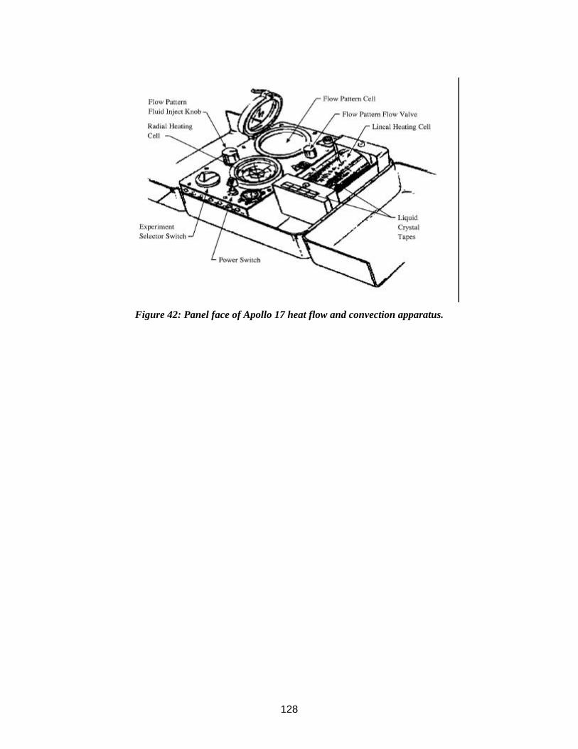
128
Figure 42: Panel face of Apollo 17 heat flow and convection apparatus.

129
Experiment Operations During Apollo EVAs Acronym: None (ALFMED)
PI/Engineer: Richard E. Benson/JSC
Apollo Flight Nos.: 11, 12, 14, 15, 16, 17
Weight: 3.5 kg - ALFMED
Manufacturer: Uncertain
Experiment: Light Flashes Experiment (Apollo Light Flash Moving Emulsion Detector)
Other Contacts: Lawrence S. Pinsky/JSC W. Zachary Osborn/Univ. of Houston; J. Vernon Bailey/JSC
Discipline: Life Sciences (2500), Animal Biology/Medical - Eyes (2538), Cosmic Radiation (2900)
Dimensions:
Apollo Experiment No.: NA
Description/Purpose—All crews since A- 11 (and perhaps some earlier) observed light flashes when in the dark or when they closed their eyes, while in transit to and from the Moon, on the surface, and in lunar orbit. On A-14 an observational schedule was first followed to test the various theories of the origin of the flashes. Flashes could be seen with the eyes open or closed when the spacecraft was dark. They discovered that it was not necessary to be dark adapted to see the flashes. This indicates that Cerenkov radiation from energetic cosmic rays traversing the eyeball, which had been the most widely accepted explanation for the light flashes, probably did not cause all or most of the flashes because light from this source is quite faint. Some of the flashes observed in space may be caused by direct ionization interactions of cosmic rays with the retina.
The ALFMED was an electromechanical device carried on A-16 & 17 that was worn on the head somewhat like a helmet and supported cosmic-radiation- sensitive emulsions around the head of the test subject. A physical record was provided of cosmic ray particles that passed through the emulsion and, in turn, through the head. A fixed vs. moving emulsion comparison allowed time resolution to I second.
Site selection—In the CM during coast periods. Casual observations from the LM were also made.
Deploying experiment—The ALFMED unit was donned like a helmet with a face shield.
Checkout of experiment—NA
Operation of experiment—The A-15 crew had observing sessions with eye shades on during the trans-lunar coasts and TECs. They reported the flashes to Mission Control real-time, Also, the CMP had an observing session in lunar orbit and the crew on the surface reported that they saw flashes while in the LM. The LMP reported that the frequency of flashes was lower when he was lying on his stomach in his hammock than when he was on his back. On A-16 & 17 two one-hour sessions were conducted, one each during trans-lunar coasts and TECs. ALFMED was worn in the first session only, eye shades were used for the second. The observation of flashes was reported to Mission Control and was correlated with ALFMED results. The event rate was higher during trans-lunar coast than TEC. Photography of the fundus of the eye before and after flight revealed no detectable changes. The CMP never saw any flashes for the entire flight of A-16, but it is worth noting that he has poor night vision.
Repairs to experiment—NA
Recovery/takedown of experiment—NA
Stowing experiment for return—NA
Were there any hazards in the experiment, i.e., hazardous materials (explosive, radioactive, toxic), sharp objects, high voltages, massive/bulky objects, tripping hazards, temperatures?—No.
Was lighting a problem?—Dark adaptation may have affected the results.
Were the results visible to the crew?—Yes, by definition.
Would you recommend any design changes?—No comments by crew.

130
Were any special tools required?—A- 11, 12, and 13 crewmembers (ALFMED) merely reported light flash observations during crew debriefings. A-14 and 15 crewmembers had a special one-hour observation period and reported the flashes to Mission Control as they occurred. A-15 crewmembers were the first to have special light-tight eye shades to provide a uniform and reproducible degree of darkness. A-16 & 17 crewmembers wore special ALFMED headgear designed to document the passage of cosmic rays.
Was the orientation of the experiment (i.e. horizontal/vertical) important? Difficult?—No.
Was the experiment successful?—Yes.
Were there related experiments on other flights? Apollo? Other?—Lab studies with humans exposed to X-rays and several types of particulate radiation have been done and show that similar light-flash sensations are observed.
Where was it stored during flight?—CM aft bulkhead locker A8 (for A-16).
Were there any problems photographing the experiment?—The emulsions recorded the passage of the cosmic rays through the film. Since one moved relative to another, coincidence of two tracks by alignment of the plates defined the time of passage. This was correlated with the times of the observations of the crew to Mission Control.
What pre-launch and cruise requirements were there? Power, thermal, late access, early recovery?—None.
What was different between training and actual operation?—No comments by crew.
Any experiences inside the CM of interest from the experiment/operations viewpoint?—No.
References:
Preliminary Science Reports
Apollo light flash investigations, in "Biomedical Results of Apollo," pp 355 - 365, NASA, Osborne, W. Z., Pinsky, L. S., Bailey, J. V.
Apollo Program Summary Report, section 8.2.2.2, Visual light flash phenomenon, JSC-09423, April 1975
Apollo 16 Technical Crew Debriefing, 5 May 1972, in JSC History Office
Apollo Stowage List - Apollo 16, MSC, 18 April 1972
Memorandum to Manager, Apollo Spacecraft Program, from Director of Medical Research and Operations, re Visual Light Flash Phenomenon - Apollo 15 DTO Assessment Report, 18 October 1971, in JSC History Office

131
Figure 43: Interior view of ALFMED device (S-71-39590).
Figure 44: The ALFMED device as worn during light flashes investigation (S-71-39591).

132
Experiment Operations During Apollo EVAs Acronym: LTD
PI/Engineer: Kaleel L. Abdalla/LeRC
Apollo Flight Nos.: 14
Weight: 4.1 kg
Manufacturer: Lewis RC
Experiment: Liquid Transfer Demonstration
Other Contacts: Edward W. Otto, Eugene P. Symons, Donald A. Petrash/LeRC
Discipline: Fluid Dynamics (1700) Materials Science - Fluids (2610) Materials Science - Fluids (2610)
Dimensions: 25 x 15 x 3 cm
Apollo Experiment No.: None
Description/Purpose—The demonstration had two sets of tanks, one set containing baffles and the other without baffles. The unit was - 25 cm x 15 cm x 3 cm (estimated from photo), plus a small hand pump and 2 plastic tubes. The tanks were 10. 16 cm in diameter, and the flat faces were separated by .635 cm. Each tank contained two ports positioned 180' apart. The flat sides were clear for photographic purposes. The side which faced the light was frosted for diffuse lighting. The pump was a screw-driven piston providing a positive pressure on one side while creating a suction on the other side. It could be operated in either direction. By attaching tubing to the vent of each tank, the system became closed. The tubing, sized for friction fit over pump and tank port connections, could be easily switched to permit pumping between the baffled tank set or between the plain tank set.
Transfer of liquid between the unbaffled tanks was unsuccessful, as expected. Different flow rates were obtained by different crank speeds on the pump. Transfer between the baffled tanks demonstrated the effectiveness of two different baffle designs. The liquid transfer demonstration clearly showed that suitable baffles inside a tank at zero-g permit positive expulsion of liquid contents, taking advantage of the surface-tension properties of the liquid. Orderly inflow into the receiver tank with no liquid loss through the gas vent was also successful.
Site selection—Unclear, probably on stowage lockers.
Deploying experiment—No comments by crew.
Checkout of experiment—No comments by crew.
Operation of experiment—One astronaut had to pump the liquid from one tank to the other with a small hand-cranked pump. Another photographed the tanks either with a motion picture sequence camera or with the onboard video camera. They did the experiment at least twice. The first time was on television. During filming with the camera, there were more bubbles present than the first time.
Repairs to experiment—None required.
Recovery/takedown of experiment—No comments by crew.
Stowing experiment for return—NA
Loading/unloading samples—Samples were pumped using a hand crank pump.
Sampling operations—None.
Were there any hazards in the experiment, i.e., hazardous materials (explosive, radioactive, toxic), sharp objects, high voltages, massive/bulky objects, tripping hazards, temperatures?—All external plastic surfaces were covered with laminated safety glass and an overlay of thin fluoroplastic to ensure maximum crew safety. The liquid used in the tanks was an inert fluorochemical, perfluorotributylamine. Its properties simulated the contact angle of most propellants on typical spacecraft materials.
Was lighting a problem?—A lighting frame, containing six incandescent lamps utilizing spacecraft power, was provided for photographic purposes.
Were the results visible to the crew?—Yes.

133
Would you recommend any design changes?—No comments by crew.
Were any special tools required?—No.
Was the orientation of the experiment (i.e. horizontal/vertical) important? Difficult?—No.
Was the experiment successful?—Yes.
Were there related experiments on other flights? Apollo? Other?—STS-53 performed the Fluid Acquisition and Resupply Equipment (FARE) experiment which moved fluids from one tank to another in zero g. A successor to this flew on STS-57.
Where was it stored during flight?—Aft bulkhead lockers A8 and A10.
Were there any problems photographing the experiment?—Not attempted since capsules were not transparent.
What pre-launch and cruise requirements were there? Power, thermal, late access, early recovery?—None noted.
What was different between training and actual operation?—No comments by crew.
Any experiences inside the CM of interest from the experiment/operations viewpoint?—Performed on TEC with live color television during a press conference. It was also filmed and photographed. A picture of the apparatus is in the Mission Report as figure 5-2.
References:
A-14 Mission Report
NASA TM X-2410, Liquid Transfer Demonstration On Board Apollo 14 During Trans-Earth Coast, 1971
Apollo Program Summary Report, section 3.6, Inflight Demonstrations, JSC-09423, April 1975
Apollo 14 Technical Crew Debriefing, 17 February 1971, in the JSC History Office
Apollo Stowage List - Apollo 14, MSC, 9 February 1971

134
Part III: Summary of Lessons Learned and Guidelines for Future Experiments
The major question for planning operations on the lunar surface involves deciding which experiments or tasks will be performed. Comments regarding overplanning of the Apollo timelines and having little time to explore and think while performing an EVA are certainly ones that have been voiced by the crews and some of the Pls of the era, but it is a complex question that must be traded off against what one would have been willing to forego in order to do more "thinking and exploring." How do we measure the improvement in sample selection vs. a greater number of samples, an increased number of measurements, or an improved deployment of an instrument? How many samples are we willing to give up? How much poorer a documentation of the samples? How many fewer magnetometer or gravimeter measurements? Each discipline would have a different set of answers.
The Apollo traverse planners tried to take these considerations into account by providing some time at most of the stations for general observations and descriptions, and by trying to arrive at an overall science consensus before the mission via the Science Working Panel, as to what was a reasonable bal-ance of time allocations among the various experiments. Certainly, in the early missions the EVA timelines were scheduled very tightly. In the later J missions, however, more EVA time, better training, and an emphasis on exploration resulted in a more relaxed approach to the field geology experiment. It is questionable whether Apollo would be done any differently today if we were going back to the Moon with the same constraints on time available at a given site. When we have a permanent outpost and an opportunity to have longer visits to an area, this approach may change. It must be realized, however, that this will not happen even in the first few years of an outpost. The number of potentially interesting things to do near just about any site can quickly consume all possible EVA time. Also, Apollo had months to plan and train for each mission. Similar Earth support for an equivalent effort when EVAs happen daily is probably not realistic, so more "local" planning may be essential. Add to this the consensus realized during Skylab 4, and practiced during Shuttle missions today, that some crew autonomy is necessary, and it is likely that an approach to the desired "thinking and exploring time" may result, even if some loss of efficiency also arises.
Many of the problems dealt with on the lunar surface arose from just a few novel conditions that manifested themselves in various nasty forms. Low gravity caused cables to stick up and get caught on feet, and also made it easy for instruments to tip over. Dust was a constant problem and caused abrasion, visibility, and thermal control difficulties. Operating in a pressure suit limited a person's activity, especially in the hands and waist. From the operations described in this document, the lessons learned are listed below.
Cables were used to carry power and commands from, and data to, the ALSEP central station. Ribbon-type cables were used, and these were tightly wound on spools weeks before launch and tended to retain this "set." Normal round cables were used for other equipment, such as the television camera and the S-band antenna. All the cables were constantly getting under foot since the low gravity was not enough to cause them to lay flat. This was probably the biggest nuisance (and also a hazard) during EVA operations on the Moon. After the HFE was damaged by pulling the cable loose from the central station by tripping over it, the connections were strengthened and strain relief was added, but the cables themselves were still a problem. Also, instruments with a high center of gravity, such as the SIDE, were easily pulled over by the normal tension of the cables. Future missions might consider including "tent stakes" to anchor cables or instruments. Also, using some other way of transmitting data to (would optical pulses work in the bright lunar environment?) and power from (microwave or laser beaming?) a central station would avoid cables. If each instrument were individually powered by its own solar panels and returned data directly to Earth, as the PSEP on Apollo 11, the problem would disappear. Of course, power during the night is still required for many experiments and the benefit of a common power source is considerable.

135
Orientation of the experiments was mostly done using a bubble level and Sun compass. Leveling the experiments was generally not a problem since fairly gentle slopes were usually available. The very sensitive seismometers needed to be re-leveled frequently by command from Earth, especially during terminator crossing. The Far UV camera presented something of a problem in leveling. Two of its three feet needed to pushed deeply into the soil to level it. Most likely, leveling will not be a major problem in the future. It is an engineering problem that is constrained by mass available to the design.
Since Apollo missions always occurred in the lunar morning, and since the missions were short and the geometry of the Sun at emplacement was known, the shadow technique worked well for directional orientation. Shadow position for the planned landing site was marked on the instruments before Earth launch. If EVAs from a future lunar base are performed under varying Sun angles, a new orientation procedure for directional pointing will be needed. This could be as simple as using the same Sun compass concept with updated information from Mission Control (except near lunar noon--during which EVAs may be restricted due to thermal loads anyway), or as complex as having the equivalent of a global positioning network around the Moon. EVAs performed with only Earthshine obviously cannot use Sun orientation for emplacement.
Dust got everywhere. It even got into the areas where the release bolts were located and made it difficult to even deploy some experiments. Future thermal and mechanical designs must allow for this. Dust covers that encase the entire instrument, not just a sample port, might be included that are left on, and removed only when everything is set up correctly.
Intricate manipulation was extremely difficult with the pressure suit gloves on. Even carrying the ALSEP out to the deployment site, a task which required gripping, was difficult because of the constant effort required to close the hand. Simple operations which do not rely on a closed hand will be easiest until glove design improves. Bending of the arms and wrist was also difficult. Tasks near the chest, such as putting a sample into a bag, were therefore awkward and became a two-man operation. Bending the legs was easy, but kneeling in the dust would create a housekeeping problems upon entering a spacecraft or habitat.
While the LRV worked very well, negotiating slopes sidewise was difficult for the downhill crewman who felt as if he could easily fall off despite the seat belt. Also, once the mass of the LRV started going downhill, steering was marginal since the inertia would keep it going in a straight line. Perhaps the suspension can be made to compensate for some amount of side slope, and the wheel design can grab the surface more. Cone wheels seem to have some advantages and will probably be used instead of the wire mesh wheels of the LRV. If the weight of the vehicle is increased by filling empty containers with regolith, would that improve traction? Would this also increase the downhill steering problem and power consumption? Is there one optimum or does it depend on the particular mission on that EVA?
Low gravity is the norm on the Moon, therefore equipment easily tipped over if the center of gravity was too high and cables pulled on them. Perhaps future experiments could include "tent stakes" or incorporate pockets for weight to be added if this is a problem. The use of loose regolith as the weight could create a dust problem, so rocks, sintered soil, or cast basalt might be used as the ballast.
Digging and drilling was very difficult below the top few centimeters of the lunar regolith. The soil very quickly becomes consolidated beyond any normal soil here on Earth. Core tubes and drill stems were redesigned to work properly. To assist the removal of the long core tubes, the treadle and jack were designed. While much of this is now understood, it would be wise to reconsider how these operations can best be accomplished in the future.
Since each crewman had to place his geological samples into a bag which hung on the PLSS of the other crewman, their proximity to each other was necessarily close. Future sampling operations might benefit from allowing a crewman to place samples in a bag hanging on his own PLSS (requiring high flexibility in the suit or tools) or perhaps from using a sack that can rest on the ground with a handle that can be reached for carrying like a shopping bag. In general, teamwork which is required only due to mobility

136
and dexterity limitations should force consideration of other ways of accomplishing the task. This could effectively double the sampling activity of an EVA team.
On foot, navigation appears to have been the most difficult problem encountered during lunar surface activities. Unexpected terrain features, as compared to relief maps available from orbital reconnaissance, were the source of these problems. The ridges and valleys had an average change in elevation of -3 to 5 meters. Landmarks that were clearly apparent on the maps were not at all apparent on the surface. Even when the crewmen climbed to a ridge, the landmark often was not clearly in sight. During their short stay times, at least one landmark, the Sun, was always in sight and always reliable. This will not be the case at a future outpost when long stay times are the norm.
Later crews used the LRV, which had excellent navigation aids. A total of 5 hours was spent at traverse station stops on A-15, and the astronauts transmitted excellent descriptions of the lunar surface while in transit between stations. A-16 and 17 improved upon this. While most future EVAs can also expect to be supported by a rover, emergency walk-backs might need to be supported with better navigational aids.
In a more general sense, the interaction of experiments during Apollo created a logistical quagmire that had to be carefully considered. The magnets in the SIDE and CCG had to be a minimum distance from the magnetometer. The lunar neutron probe had to be emplaced a minimum distance from the RTG. The vibrations of the LRV due to moving the TV camera were a concern to the traverse gravimeter team. The layout of the ALSEP packages was driven by interactions of the instruments and their various orientation requirements. While intermingling many experiments from both a hardware and a timeline perspective may be necessary for efficiency, there is always a price to pay in compromising the data or operations required.
During the Apollo EVAs, the planned timelines were carefully followed by teams of mission controllers and science support people in the back rooms. Rarely were the crews "allowed" to get far behind this timeline. Some tasks, such as deploying the rover or transferring the fuel rod to the RTG, were critical, and whatever was needed to accomplish them was done. In these cases, something else had to be sacrificed. That usually meant shortening the time at one of the stations on the geology traverse, or eliminating the station altogether. Some special samples were eliminated or obtained at alternate locations. It is doubtful that this much support will be provided to future crews when EVA is a daily occurrence. What is lost in efficiency will hopefully be made up for in sheer quantity of time at the outpost.
As our experience with training for and performing lunar surface EVAs grew with later missions, our ability to plan realistic timelines increased. The A-14 crew said that, by the end of training, they were consistently ahead of the timeline by 25 to 30 minutes, and felt that this would be adequate to take care of the extra time that they would use on the surface in being more careful, and to allow for problems. As it turned out, it wasn't enough. "The fact is that you're just a bit more careful with the actual flight equipment." They recommended a 25% to 30% pad.
An analysis of the three EVAs of Apollo 15 was performed and is documented in a series of charts and tables on file at the JSC History Office under the title "Apollo 15 Realtime Lunar Surface Summary Timelines, Activity Completion Percentages Attached." It compares the actual time required to complete all the tasks on the surface to the planned timelines. It also shows percentage of completion of each task and has some comments on the comparisons. A similar document could not be found in the Apollo Collection for the other missions. One would need to view the mission video and audio tapes and compare them to the timelines to get this information.
The Apollo 16 Time and Motion Study looked at the ratio of time to perform tasks related to ALSEP deployment on the lunar surface on A-15 and A-16 vs. the time the crew took on their third one-g training session. This ratio ranged from 1.16 for simple tasks to 2.18 for more complex ones. The average ratio on A-15 was 1.41, and that on A-16 was 1.66. The difference is not statistically significant. This suggests that tasks take about 50% longer to perform under the lunar EVA constraints than in training.

137
A number of factors can be proposed to explain the differences in lunar EVA and one-9 training comparisons. The more obvious of these are rooted in the differences associated with lunar and Earth-bound conditions-g level, differences in soil and terrain, visibility, etc. There are also attitudinal influences which are important. Central to these is the attitude of care or carefulness. The equipment was not indestructible and the crew had very limited repair capability. During lunar EVA the astronaut had no one to correct mistakes or to help in difficult situations, in contrast to a training session where numerous individuals were available to check experiment deployment. The simulated lunar surface at KSC was not only smoother than the actual lunar terrain, but was also more familiar and created no problems relative to site selection for experiment deployment. When on the Moon, the astronaut was keenly aware of the fact that he had only one chance to complete his task, that his performance must be efficient, and that he was being intently observed by a large portion of the world population. In short, lunar EVA induced an attitude of great care in the execution of the allotted tasks.
There are also the matters of rest and pacing. During training, it is not possible to continue working for very long in the suited condition. Work periods are shorter and astronauts tend to mobilize their energies for swift but effective performance. Training time, then, would tend to be shorter.
A future lunar program will have to learn from its mistakes as well as its successes, just as the Apollo missions did. It is important to build upon what we have already learned, however. This document will hopefully help us to retain the corporate knowledge of Apollo operations until we get back to do it even better next time.

A-1
Appendix A - Apollo Experiments and Missions
Surface Apollo Mission Number Experiment 11 12 14 15 16 17
S 031 Passive Seismic X X X X X S 033 Active Seismic X X S 034 Lunar Surface Magnetometer X X X S 035 Solar-Wind Spectrometer X X S 036 Suprathermal Ion Detector X X X S 037 Heat Flow X (1) X S 038 Charged Particle X S 058 Cold Cathode Gage X X X S 059 Lunar Geology X X X X X X S 078 Laser Ranging Retroreflector X X X S 152 Cosmic Ray Detector X X S 198 Portable Magnetometer X X S 199 Traverse Gravimeter X S 200 Soil Mechanics X X X X X X S 201 Far UV Camera/Spectrograph X S 202 Lunar Ejecta and Meteorites X S 203 Lunar Seismic Profiling X S 204 Surface Electrical Properties X S 205 Lunar Atmospheric Composition X S 207 Lunar Surface Gravimeter X S 229 Neutron Probe X M 515 Dust Detector X X X X X Time on Moon (hours) 22 32 33 67 71 75 Number of EVAs 1 2 2 3 3 3 Duration of EVAs (hours) 2.8 7.8 9.4 18.6 20.2 22.1 Total Traverse Length (km) 0.25 2.0 3.3 27.9 27.0 35.0 (1) Cable broken during deployment. Microgravity Apollo Mission Experiment 11 12 14 15 16 17
Composite Casting Demonstration X Electrophoresis Demonstration X X Heat Flow and Convection Demonstration X X Light Flashes Experiment X X X X X X Liquid Transfer Demonstration X


B-1
Appendix B - Bibliography
Internal JSC documents only, archived at the JSC History Office A- 11 Final Lunar Surface Operations Plan, JSC, 27 June 1969. A- 12 Final Lunar Surface Operations Plan, JS C, 23 October 1969. A-14 Final Lunar Surface Procedures, 31 December 1970. A- 15 Final Lunar Surface Procedures, 9 July 1971. A-16 Final Lunar Surface Procedures, 16 March 1972, MSC. A-17 Final Lunar Surface Procedures, Vol. 1: Nominal Plans, MSC, 6 November 1972. A- I I Mission Report - MSC-00 17 1, November 1969 (available from NASA as SP-23 8). A-12 Mission Report - MSC-01855, March 1970. A-14 Mission Report - MSC-04112, May 1971. A-15 Mission Report - MSC-05161, December 1971. A-16 Mission Report - MSC-07230, August 1972. A-17 Mission Report - JSC-07904, March 1973. A- 14 Stowage List, MSC, 9 February 1971. A-16 Stowage List, MSC, 18 April 1972. A-17 Stowage List, MSC, 12 December 1972. A- 14 Technical Crew Debriefing, 17 February 1971. A-15 Technical Crew Debriefing, 14 August 1971. A-16 Technical Crew Debriefing, 5 May 1972. A-17 Technical Crew Debriefing, 4 January 1973. ALSEP (Array E) Critical Design Review Presentation Material, NAS9-5829. NASA/MSC. Bendix
Aerospace Systems Division. 14-18 June 1971. ALSEP (Array E) Apollo 17 Familiarization Course - Handout for class of 15 January 1968. ALSEP (Array E) Apollo 17 Familiarization Course - Handout for class of I September 1972. ALSEP Final Systems Mission Rules - ALSEP 3. 23 March 1970. ALSEP Flight System Familiarization Manual, Bendix Aerospace Division, Contract No. NAS9-5829,
1 August 1967. Alignment, Leveling, and Deployment Constraints for A- 15 Lunar Scientific Experiments, document in
JSC History Office. Apollo Experience Report #17 - Thermal Design of Apollo Lunar Surface Experiments Package. Apollo Experience Report #37 - Photographic Equipment and Operations During Manned Spaceflight
Programs. Apollo 15 Realtime Lunar Surface Summary Timelines, Activity Completion Percentages Attached. Apollo Program Summary Report, JSC-09423. April 1975. Catalog of Apollo Lunar Surface Geological Sampling Tools and Containers, JSC-23454. Geotechnical Engineering on the Moon, document from the Planet Surface Systems Office, JSC.
December 1990. Memorandum from FC93/Head, Lunar Surface Section, 7 October 1971, re: Apollo 14 ALSEP 4 Post-
Mission Report. Memorandum to Manager, Apollo Spacecraft Program, from Director of Medical Research and
Operations, re Visual Light Flash Phenomenon - Apollo 15 DTO Assessment Report. 18 October 1971.
Memorandum from Leon T. Silver to members of the SWP Subpanel on Soil Mechanics Experiment (S200). 30 November 1971.
Personal files of Col. R. Parker, available in JSC History Office. NASA documents A-11 Preliminary Science Report - NASA SP-214, 1969. A-12 Preliminary Science Report - NASA SP235, 1970. A-14 Preliminary Science Report - NASA SP 272,1971. A-15 Preliminary Science Report - NASA SP289, 1972. A-16 Preliminary Science Report - NASA SP-315,1972. A-17 Preliminary Science Report - NASA SP-330,1973. ALSEP Termination Report, NASA RP 1036, April 1979. Analysis of Surveyor 3 Material and Photographs Returned by Apollo 12, NASA SP-284. 1972. Apollo 14 Composite Casting Demonstration Final Report, NASA TM X-61641. October 1971.

B-2
Appendix B - Bibliography (continued)
NASA documents (continued) Apollo Scientific Experiments Data Handbook, JSC-09166, NASA TM X-5 813 1, August 1974. Apollo 17 Heat Flow and Convection Experiments - Final Data Analyses Results, NASA TM X-64772. Electrophoresis Separation in Space - Apollo 14, NASA TM X-64611. 1971. Electrophoresis Separation in Space - Apollo 16, NASA TM X-64724. 1972. Heat Flow and Convection Demonstration (Apollo 14), NASA TM X-64735. 1973. Liquid Transfer Demonstration Onboard Apollo 14 During Trans-Earth Coast, NASA TM X-2410.
November 1971. The Apollo Spacecraft - A Chronology, NASA SP-4009, Vol. 4. Technical Journal Articles and Books "Heat Flow and Convection Experiments Aboard Apollo 17." Science. Vol. 187. pp. 165-167. 1975. Berg, 0. E., F. F. Richardson, J. W. Rhee, and S. Auer. "Preliminary Results of a Cosmic Dust
Experiment on the Moon." Geophy. Res. Lett. 1. pp. 289-290. 1974. Berg, 0. E., H. Wolf, and J. Rhee. "Lunar Soil Movement Registered by the Apollo 17 Cosmic Dust
Experiment," in Interplanetary Dust and Zodiacal Light, H. Elsasser and H. Fechtig, eds. SpringerVerlag. New York. pp. 233-237. 1976.
Carruthers, George R. "Apollo 16 Far-Ultraviolet Camera/Spectrograph: Instrument and Operations," Applied Optics. Vol. 12, pp. 2501-2508. October 1973.
Criswell, D. R. "Lunar dust motion," in: Proc. 3rd Lunar Sci. Conf., The MIT Press, Cambridge, MA, 2671-2680. 1972.
Heiken, G., D. Vaniman, and B. French, Eds. Lunar Sourcebook - A User's Guide to the Moon. Cambridge University Press. Cambridge, MA. 1991.
Jacobs, S., R. E. Durkee, and R. S. Harris, Jr. "Lunar Dust Deposition Effects on the Solar Absorptance of Thermal Control Materials," AIAA paper. AIAA 6th Thermophysics Conference, Tullahoma, TN. pp. 71-459. 26-28 April 1971.
Jones, Eric M. "Working on the Moon." Proceedings of Space'90, ASCE. pp. 1423-1432. 1990. King, Bert. Moon Trip - A Personal Account of the Apollo Program and its Science. University of
Houston. Houston, TX. 1989. Mamon, Glenn. A Traverse Gravimeter for the Lunar Surface. MIT Draper Labs. Cambridge, MA.
August 1971. Osborne, W. Z., L. S. Pinsky, and J. V. Bailey. "Apollo Light Flash Investigations," in Biomedical
Results of Apollo. NASA. pp. 355-365. Page, Thornton. "S201 Far-Ultraviolet Photograhs of Comet Kohoutek From Skylab 4 (SL4),
Preliminary Report," in: Comet Kohoutek, proceedings of a workshop held at MSFC. pp. 37-75. 13-14 June 1974.
Page, T. and G. R. Carruthers. NRL Report 8206: S201 Far Ultraviolet Atlas of the Large Megellanic Cloud. 1978.
Rennilson, J. J. and D. R. Criswell. "Surveyor Observations of Lunar Horizon Glow," The Moon 10, pp. 121-142. 1974.
Wilhelms, Don E. To a Rocky Moon, A Geologist's History of Lunar Exploration. University of Arizona Press. Tucson, AZ. 1993.
Zook, H. A. and J. E. McCoy. "Large Scale Lunar Horizon Glow and a High Altitude Lunar Dust Exosphere." Geophys. Res. Let., Vol. 18, No. 1, 2117-2120. 1991.
Personal communications Personal communication with Jim Bates, 21 April 1993, re: ALSEPs. Personal communication with Dallas Evans/JSC, 25 March 1993. Personal communication with Eric Jones, 3 August 1993. Personal communication with Thomton Page. Personal communication with Jack Sevier, 18 May 1993. Personal communication with Joseph N. Tatarewicz. Personal communication with John Young, I April 1993. Personal communication with Herb Zook, I April 1993, re: ALSEP command procedures.

Index-1
Index
Active Seismic Experiment (ASE) 1, 5, 6, 8, 10, 81, 85, 105, A-1 Apollo Light Flash Moving Emulsion Detector (Light Flashes Experiment) (ALFMED) 153, 154, 155,
156, A-1, B-2 Apollo lunar hand tools (ALHTs) 8, 72 Apollo lunar sample return container (ALSRC) (also SRC) 65, 71 Apollo Lunar Stereoscopic Closeup Camera (ALCC) 11, 133, 134, 135 Apollo Lunar Surface Experiments Package (ALSEP) 1, 2, 5-9, 11, 13, 15-17, 19, 20, 22, 29, 30, 34, 41,
42, 44, 45, 49, 50, 53, 57-59, 61, 62, 72, 73, 75, 76, 85, 86, 89, 90, 98, 99, 103, 104, 105, 117, 121-124, 130, 159-162, B-1, B-2
Apollo lunar surface drill (ALSD) 7, 51, 52, 67, 72, 75, 76, 99, 110 Apollo Simple Penetrometer (ASP) 2, 109 astronomy 37 aurora 37 barbell 5, 6, 10, 103 BB 34, 105 bore stems 50-52 Boyd bolts 6, 98, 117, 122, 123 cable 1, 2, 4, 9, 19, 20, 22, 37, 50, 51, 61, 65, 89, 93, 94, 97, 101, 103, 107, 110, 121, 122, 125, 129,
159 cameras 11, 12, 13, 37-39, 81, 109, 140, 144 central station 1-3, 6-10, 22, 29, 41, 49-51, 57, 61, 63, 66, 75, 86, 89, 102, 103, 107, 117, 121, 122, 130,
159, 160 Charged Particle Lunar Environment Experiment (CPLEE) 5, 15, 17, 123, A-1 Cold Cathode Gauge Experiment (CCG) (CCGE) (CCIG) 5, 19, 20, 22, 58, 89, 121, 123, 124, 161, A-1 Composite Casting Demonstration 137, A-1, B-I core tube 67, 72, 74, 101, 109-111, 161 cosmic ray (radiation) 23, 25, 153 Cosmic Ray Detector (CRD) (CRDE) (CRE) (also Lunar Surface Cosmic Ray Experiment, or LSCRE)
23, 26, 77, 114, A-1 cratering 61 Data Acquisition Camera (DAC) 11, 137, 147, 149, 150 Data Storage Electronics Assembly (DSEA) 125, 126 dome removal tool (DRT) 8, 97-99, 102 drill(ing) 7, 49, 50, 67, 68, 72, 76 dust (lunar) 2, 3, 6, 7, 11, 12, 24, 29, 30, 39, 62, 75, 80, 81, 97-99, 103, 104, 113, 114, 122, 124, 126,
129, 133, 159, 160, A-1 Dust, Thermal & Radiation Engineering Measurements (DTREM) (also Lunar Dust Detector, or LDD)
29, 39, A-1 Early Apollo Scientific Experiment Package (EASEP) 8, 33, 35, 103, 109 Earth atmosphere 37, 39 Earth sciences-magnetosphere 117, 121 electrophoresis 139, 143, 145, A-1, B-I equipment transfer bag (ETB) 11, 12, 38, 99, 114, 126, 133 erectable S-band antenna 97, 159 explosives 1, 57, 85, 86, 87, 104, 128 Far UV Camera/Spectrograph (UVC) 37, 38, 40, 160, A-1, B-2 flag 4, 97, 98, 101 fuel cask 6, 26, 102 fuel transfer tool (FTT) 8, 97-100, 102 geochemistry 125 geophones 1-4, 6, 85, 86, 107, 110

Index-2
Index (continued)
gnomon 8, 11, 54, 62, 66, 67, 74, 81, 104, 110, 112 grand prix 11, 82 gravimeter 41 grenades 1-3 hammer 6, 67, 71, 72, 75, 98, 111, 114 heat flow 49 Heat Flow and Convection Experiment (HFC) 147, 149, A-1, B-1 Heat Flow Experiment (HFE) 5, 6, 49, 50, 52, 72, 85, 159, A-1 Laser Ranging Retroreflector (LR3) (LRRR) 2, 33, 35, 53-55, 103, A-1 Liquid Transfer Demonstration (LTD) 157, A-1, B-2 lunar atmosphere 19, 37, 57, 58, 121 Lunar Atmosphere Composition Experiment (LACE) 5, 20, 57, 59, A-1 lunar communications relay unit (LCRU) 81, 82 Lunar Dust Detector (LDD) (also DTREM) 5, 29, 62 Lunar Ejecta and Meteorites (LEAM) 5, 30, 61-63, 130, A-1 lunar equipment conveyor (LEC) 65, 97, 98 lunar geology 41, 45, 49, 61, 65, 125 lunar geosciences 65, 71 lunar gravimetry 41, 45 lunar magnetometry 89, 93 Lunar Mass Spectrometer (LMS) (also LACE) 57 Lunar Neutron Probe Experiment (LNPE) (also NFE) 25, 75, 78 lunar rover vehicle (LRV) 1, 3, 6, 8, 45-48, 53, 65, 66-68, 72, 74, 79-81, 83, 85, 87, 97, 99, 109, 110,
125, 126, 130, 160, 161 Lunar Seismic Profiling Experiment (LSPE) 4-6, 8, 57, 61, 81, 85-87, 105, 128, A-1 lunar seismology 1, 85 lunar seismometry 103 Lunar Surface Cosmic Ray Experiment (LSCRE) 23, 24, 26, 77, 114 Lunar Surface Gravimeter (LSG) 5, 41, 44, 46, 63, 105, A-1 Lunar Surface Magnetometer (LSM) 5, 19, 20, 89, 91, 93, 94, A-1 Lunar Surface Ultraviolet Camera (LSUC) (also UVC) 37 Lunar Tidal Gravimeter (also LSG) 41 Lunar Portable Magnetometer (LPM) 93-95, A-1 magnetosphere 117, 121 mass spectrometer 20, 57, 58, 114 micrometeorites 61, 62 Modularized Equipment Stowage Area (MESA) 8, 51, 66, 75, 77, 80, 86, 97, 98, 101, 114 Modularized Equipment Transporter (MET) 1, 53, 65, 66, 71, 93, 95, 97, 99, 101, 109, 133 mortar 1, 2, 4, 6, 10 mortar package assembly (MPA) 1, 2, 4 Neutron Flux Experiment (NFE) (also LNPE) 75, A-1 Passive Seismic Experiment (PSE) (PSEP) 4, 5, 30, 33-35, 49, 53, 103-106, 107, 160, A-1 penetrometer 2, 110, 111 portable life support system (PLSS) 11, 38, 66, 67, 74, 79, 93, 98, 104, 121, 123, 129, 161 probe emplacement tool 51, 52 radiation 15, 23, 75, 121 rake 67, 72, 74 rammer 51, 111 Radioisotope Thermal Generator (RTG) 5, 6, 8, 9, 26, 44, 49, 63, 75, 97, 99, 100, 102, 103, 107, 161 sample collection bags (see also SRQ 71 sample return container (bag) (SRC) (also ALSRQ 71, 113, 114, 128, 133

Index-3
Index (continued)
Scientific Equipment Bay (SEB) 5, 34, 37, 39, 54, 90, 93, 94 scoop 48, 66, 72 seismometer 1, 3, 5, 41, 103, 105, 160 Self-Recording Penetrometer (SRP) 109, 110 SNAP-27 (RTGs) 8, 99 Soil Mechanics 2, 11, 67, 71, 109-111, A-1, B-I solar physics 113, 117 solar wind 5, 15, 23, 37, 109, 113, 114, 117, 121 Solar Wind Composition Experiment (SWC) 109, 111, 113, 115, 116, 118 Solar Wind Spectrometer Experiment (SWS) (SWE) 5, 114, 117, 119, A-I space physics 41, 45 Suprathermal Ion Detector Experiment (SIDE) 5, 16, 19, 20, 22, 121-124, 159, 161, A-1 Surface Electrical Properties (SEP) Experiment 81, 125-128, A-1 Surveyor 3 (111) (S3) 25, 30, 129, 134 thermal degradation samples (TDS) 11, 130, 133 thumper 1, 2, 3, 8, 110 tongs 70, 72 traverse gravimeter 42, 161, B-2 Traverse Gravimeter Experiment (TGE) 45, 46, 48, 128, A-1 treadle 67, 75, 76, 161 trench(ing) 67, 72, 110, 112 TV (camera) 2, 11, 45, 68, 82, 97, 98, 109, 129, 130, 140, 148, 158, 159, 161 universal handling tool (UHT) 3, 7, 8, 16, 41, 42, 51, 53, 54, 58, 62, 89, 90, 97-99, 105, 117, 118, 121-
123 UV 30, 37, 39 vise 71 yo-yo 65


![The Planetary Seismic Experiments - DARTS at … The Description of Apollo Seismic Experiments R. Yamada (1) Apollo Passive Seismic Experiment (PSE) [General Description] Passive seismic](https://img.dokumen.tips/doc/110x75/5ae6f5957f8b9a08778db9d4/the-planetary-seismic-experiments-darts-at-the-description-of-apollo-seismic.jpg)


![The Planetary Seismic Experiments - JAXA...The Description of Apollo Seismic Experiments R. Yamada (1) Apollo Passive Seismic Experiment (PSE) [General Description] Passive seismic](https://img.dokumen.tips/doc/110x75/5eaa08d3e7b9de66361fa7f5/the-planetary-seismic-experiments-jaxa-the-description-of-apollo-seismic-experiments.jpg)