Embed Size (px)
Citation preview

CatalogD 11.7
Part 12013
Answers for industry.
SINAMICS Drives
SINAMICS G150 NEMA Enclosed Drives

Siemens D11.7 – 2010
Related Catalogs The Engineering ManualSINAMICS G130 Drive Converter Chassis Units SINAMICS G150 Drive Converter Cabinet Units
Catalog D 11 • 2011
SINAMICS Drives
Answers for industry.
SINAMICS G130 D11 • 2011Drive Converter Chassis UnitsSINAMICS G150Drive Converter Cabinet Units (IEC)E86050-K5511-A101-A5-7600DRCA-D1100-0412
SINAMICS and Motors for Single-Axis DrivesCatalog D 31 • 2012
Motion Control Drives
Answers for industry.
SINAMICS and Motors for Single-Axis Drives D31 • 2012
E86050-K5531-A101-A1-7600DRCA-D3112-0412
SINAMICS Low Voltage Engineering Manual
Engineering Manual for SINAMICS G130 Drive Chassis, SINAMICS G150 Enclosed Drives, SINAMICS S120 Drive Chassis, SINAMICS S120 Cabinet Modules, SINAMICS S150 Enclosed Drives
The engineering manual is divided into the following chapters: - Fundamental Principles and System Description - EMC Installation Guideline - General Engineering Information for SINAMICS - SINAMICS G130 Converter Chassis Units - SINAMICS G150 Converter Cabinet Units - SINAMICS S120 Chassis Format Units and Cabinet Modules - SINAMICS S150 Converter Cabinet Units - Drive Dimensioning - Motors
This manual offers users comprehensive support for the configuring of drives and associated system components.
The first three chapters are devoted primarily to the fundamental physical principles of variable speed electric drives and include EMC Installation Guidelines as well as general system descriptions and planning information which relate to all products in the SINAMICS range. The other chapters then discuss in detail questions relating to the dimensioning of specific drive models as well as the selection of suitable motors.
Note: The engineering manual is not available as a printed hard copy, but only as an electronic file in PDF format.
SINAMICS S120 Chassis Format Units and Cabinet Modules
SINAMICS S150 Converter Cabinet UnitsCatalog D 21.3 • 2011
SINAMICS Drives
Answers for industry.
SINAMICS S120 Chassis Format Units and Cabinet Modules
SINAMICS S150 Converter Cabinet UnitsCatalog D 21.3 • 2011
SINAMICS Drives
Answers for industry.
SINAMICS S120 D21.3 • 2011Chassis Units and Cabinet Modules (IEC)SINAMICS S150Drive Converter Cabinet Units (IEC)E86060-K5521-A131-A3-7600DRCA-21300-0412
SIMOTION, SINAMICS S120 and Motors for Production MachinesCatalog PM 21 • 2011
Motion Control
Answers for industry.
SIMOTION, SINAMICS S120 andMotors for Production Machines Catalog PM 21 • 2011
E86060-K4921-A101-A2-7600DRCA-K4921-0111
SIMOTICS NEMA Motors
www.usa.siemens.com/nema-motors
Low Voltage AC Motors Selection and Pricing Guide
Catalog D81.2 - 2012, USA Edition
Low Voltage AC Motors D81.2 • 2012Selection and Pricing Guide, USA Edition
NMPC-00600-0212
SIMOTICS Low-Voltage Motors Type series 1LE, 1PC, 1LA, 1LG, 1LL, 1LP, 1MA, 1MJ, 1PP, 1PQ Frame sizes 63 to 450 Power range 0.09 to 1250 kW
Catalog D 81.1 • January 2012
Motors
Answers for industry.
Inte
rnational Efficiency
IE changeover
Standard Ef ciency
High Ef ciency
Premium Ef ciency
SIMOTICS Low-Voltage Motors (IEC) D81.1 • 2012Frame sizes 63 to 450Power range 0.09 to 1250 kW
E86060-K5581-A111-A4-7600
SINAMICS GM150, SINAMICS SM150Medium Voltage Converters D12 • 2012 E86060-K5512-A101-A3-7600
SINAMICS S120 Cabinet ModulesNorth American Edition D21.7 (part 1) • 2013
DRCA-D2171-0313

The Engineering Manual SINAMICS DrivesSINAMICS G150 NEMAenclosed drivesSINAMICS G150 NEMAenclosed chassis
Catalog D11.7 (Part 1) – 2013
The products andsystems described in this catalog are produced/distributed inaccordance with the requirementsof a qualitymanagementsystem which hasbeen certified to ISO 9001:2008.
Introduction
SINAMICS G150 NEMAType A enclosed drives
SINAMICS G150 NEMAType C enclosed chassis
Engineering information
TrainingService and support
1
2
3
4
Quality

SINAMICS G150 NEMA
Introduction
1
Siemens D11.7 (Part 1) – 2013
The SINAMICS drives family
0/2
One Family, One Source, All Applications
ApplicationSINAMICS is the family of drives from Siemens designed for industrial applications that offers solutions for all drive tasks:
Basic pump and fan applications in the process industry. Complex single-motor drives in centrifuges, presses,
extruders, elevators, as well as conveyor and transport systemsCoordinated drive line-ups for textile, plastic film, and
paper machines, as well as for rolling millsHigh precision servo drives for machiningHighly dynamic servo drives for machine tools, as well as
packaging and printing machines
Product variantsThe SINAMICS range offers the ideal variant for all drive tasks:SINAMICS G is designed for standard applications,
mostly with induction motors, that have less stringent requirements on the dynamic performance.SINAMICS S handles complex drive tasks with synchronous
or induction motors and fulfills the most stringent requirements regarding. - the dynamic performance and control accuracy - integration of extensive technological functions in the drive control system.
Platform concept and Totally Integrated AutomationAll SINAMICS versions are based on a platform concept. Common hardware and software components, as well as standardized tools for design, configuration, and commissioning tasks ensure high-level integration across all components. SINAMICS covers the full range of drive applications. The different SINAMICS versions can be easily combined with each other.
SINAMICS is part of the Siemens “Totally Integrated Automation” concept. Integrated SINAMICS systems covering engineering, data management and communication at the automation level, result in extremely cost effective solutions based on SIMOTION (motion control), SINUMERIK (machine tool) and SIMATIC (PLC and DCS) control systems. Quality management to ISO 9001SINAMICS meets the highest quality requirements.Comprehensive quality assurance measures in all development, engineering and production processes ensure a consistently high level of quality.
Of course, our quality management systems are certified by independent authorities in accordance with ISO 9001.

5
SINAMICS G150 NEMAIntroduction
1/2 The members of the SINAMICS drives family SINAMICS low voltage drives SINAMICS DC drives SINAMICS medium voltage drives SINAMICS G150
1
Siemens D11.7 (Part 1) – 2013

SINAMICS G150 NEMA
Introduction
1
Siemens D11.7 (Part 1) – 2013
The SINAMICS drives family
SINAMICS low voltage drives
SINAMICS G110 SINAMICS G120 SINAMICS G110D SINAMICS G120D
The versatile single motor drive for low power ratings
The modular single motor drive for low up to medium power ratings
The distributed single motor drive for basic solutions
The distributed single motor drive for high performance
Typical ratings
230 V 1 ph. AC in / 3 ph. out0.15 to 4 HP(0.12 to 3 kW)
380 to 690 V 3 ph. AC0.15 to 400 HP(0.37 to 250 kW)
380 to 480 V 3 ph. AC1 to 10 HP(0.75 to 7.5 kW)
380 to 480 V 3 ph. AC1 to 10 HP(0.75 to 7.5 kW)
Main applications
Machine and plants for industrial and commercial applications
Machine and plants for industrial and commercial applications
Horizontal conveyor applications main focus on distribution and logistics in airports; suitable for basic conveyor-related tasks with local control or connected to a bus via ASInterface
Conveyor applications in industrial environments, main focus on the automotive industry; also suitable for high-performance applications e.g. at airports and in the food, beverage and tobacco industry
Application examples
• Simple pumps and fans• Auxiliary drives• Conveyor systems• Billboards• Door/gate operating mechanisms
• Pumps• Fans• Compressors
• Conveyor systems• Airports• Distribution logistics
• Conveyor systems• Electric monorail system in distribution Logistics
Highlights
• Compact• Can be flexibly adapted to different applications• Simple and fast commissioning• Clear terminal layout• Optimum interaction with SIMATIC and LOGO!
• Modular• Can be flexibly expanded• Safety Integrated• Simple and fast commissioning• Regenerative feedback• Innovative cooling concept• Optimum interaction with SIMOTION and SIMATIC
• Low profile design with standard footprint, IP65• Easy, fast commissioning• Optional key-operated disconnect switch• AS-Interface with bus parameterization• Quick stop function• Integrated brake control• Optimum interaction with SIMATIC and LOGO!
• Low profile design with standard footprint, IP65• Modular• Can be flexibly expanded• Easy, fast commissioning• Regenerative feedback• Optimum interaction with SIMOTION and SIMATIC• SINAMICS Safety Integrated
Catalog D31 Catalog D31 Catalog D31 Catalog D31
1/2
SINAMICS G150 NEMA
Introduction
1
Siemens D11.7 (Part 1) – 2013
The SINAMICS drives family
SINAMICS low voltage drives
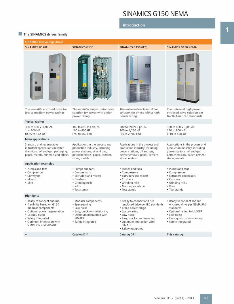
SINAMICS G120E SINAMICS G130 SINAMICS G150 (IEC) SINAMICS G150 NEMA
The versatile enclosed drive for low to medium power ratings
The modular single motor drive solution for drives with a high power rating
The universal enclosed drive solution for drives with a high power rating
The universal high power enclosed drive solution per North American standards
Typical ratings
380 to 480 V 3 ph. AC1 to 200 HP(0.75 to 132 kW)
380 to 690 V 3 ph. AC100 to 800 HP(75 to 560 kW)
380 to 690 V 3 ph. AC100 to 1,250 HP(75 to 2,700 kW)
380 to 600 V 3 ph. AC150 to 800 HP(110 to 560 kW)
Main applications
Standard and regenerative industrial applications in water, chemicals, oil and gas, packaging, paper, metals, minerals and others
Applications in the process and production industry, including power stations, oil and gas, petrochemicals, paper, cement, stone, metals
Applications in the process and production industry, including power stations, oil and gas, petrochemicals, paper, cement, stone, metals
Applications in the process and production industry, including power stations, oil and gas, petrochemicals, paper, cement, stone, metals
Application examples
• Pumps and fans• Compressors• Conveyors• Mixers• Kilns
• Pumps and fans• Compressors• Extruders and mixers• Crushers• Grinding mills• Kilns• Test stands
• Pumps and fans• Compressors• Extruders and mixers• Crushers• Grinding mills• Marine propulsion• Test stands
• Pumps and fans• Compressors• Extruders and mixers• Crushers• Grinding mills• Kilns• Test stands
Highlights
• Ready to connect and run• Flexibility based on G120 modular components• Optional power regeneration• UL508C listed• Safety Integrated• Optimum interaction with SIMOTION and SIMATIC
• Modular components • Space-saving• Low noise• Easy, quick commissioning• Optimum interaction with SIMATIC• Safety Integrated
• Ready to connect and run enclosed drive per IEC standards• Broad power range• Space-saving• Low noise• Easy, quick commissioning• Optimum interaction with SIMATIC• Safety Integrated
• Ready to connect and run enclosed drive per NEMA/ANSI standards• Optional listing to UL508A• Low noise• Easy, quick commissioning• Safety Integrated
– Catalog D11 Catalog D11 This catalog
1/3

SINAMICS G150 NEMA
Introduction
1
Siemens D11.7 (Part 1) – 2013
The SINAMICS drives family
SINAMICS low voltage drives SINAMICS DC drives SINAMICS medium voltage drives
SINAMICS S120 SINAMICS S150 SINAMICS DCM SINAMICS GM150 / SM150 SINAMICS GL150 / SL150
The flexible, modular applied drive system for demanding drive tasks
The drive solution for demanding high power single motor drives
The scalable drive system for basic and demanding applications
Drive solutions for single motor and multi motor medium voltage drives
Typical ratings
380 to 690 V 3 ph. AC0.15 to 5,000 HP(0.12 to 4,500 kW)
380 to 690 V 3 ph. AC100 to 1,250 HP(75 to 1,200 kW)
85 to 950 V 3 ph. AC5 to 24,000 HP(4 kW to 18 MW)
2.3 to 12 kV 3 ph. AC 1,250 to 100,000 HP(1 to 75 MW)
Main applications
High performance applications in all industries, including coordinated multi-motor drive systems and very high power single drives, motion control (positioning, synchronization).
High performance, fully regenerative standalone drive applications requiring clean power (low harmonics, controllable power factor)
Industrial applications in metals, plastics, printing, paper, cranes, mining, oil and gas, for new installations and retrofits.
General and high performance, very high speed and very low speed applications mainly in the process industries.
Application examples
• Machine tools• Production machines:• Presses• Converting applications• Handling equipment• Paper machines• Rolling mills • Marine applications
• Test bays• Centrifuges• Elevators and cranes• Cross cutters and shears• Downhill conveyor belts • Presses• Cable winches
• Rolling mills• Cross cutters and shears• Wire-drawing machines• Extruders and kneaders• Presses• Elevators and cranes• Cableways and lifts• Mine hoists
• Compressors• Pumps and fans• Extruders and mixers• Hot and cold rolling stands• Mine hoists• Conveyor belts• Grinding mills• Test stand drives
Highlights
• Flexible and modular• Choice of rectifier types• Fully scalable - ratings, functionality, number of axes, performance• Auto-configuration• Wide range of motors• Optimum interaction with SIMOTION, SIMATIC and SINUMERIK• Safety Integrated• Air or liquid cooled
• Ready to connect and run • High control accuracy and dynamic response• Low harmonics, exceeding IEEE 519 requirements • Tolerant of line voltage fluctuations• Reactive power compensation option• Safety Integrated
• Choice of Control Units• Integrated field power supply • Free function blocks and Drive Control Chart• Expandable functionality using SINAMICS components• Single-phase connection possible
• Compact design and high power density• Ready to connect and run enclosed drive• Simple operator control and monitoring• Extremely rugged, reliable in operation and almost maintenance free• Air and liquid cooled versions
Catalogs PM21, D21.3, D21.7 Catalog D21.3 Catalog D23.1 Catalog D12
1/4
SINAMICS G150 NEMA
Introduction
1
Siemens D11.7 (Part 1) – 2013
Application of SINAMICS G150
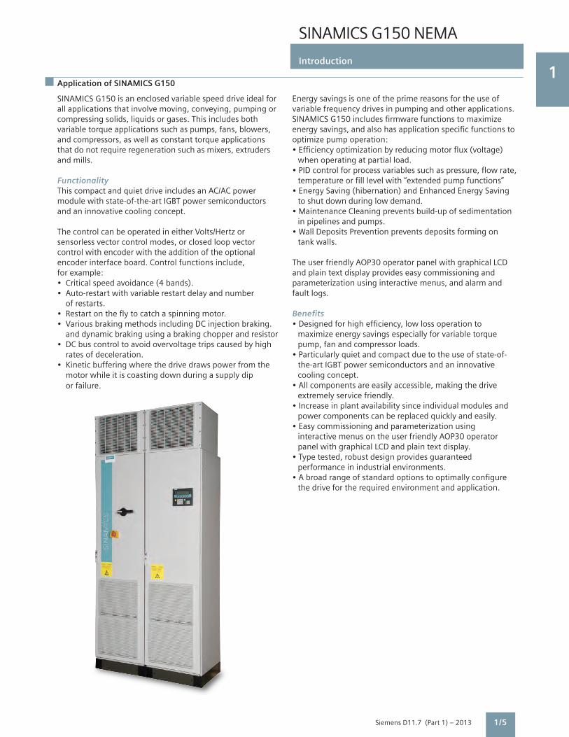
SINAMICS G150 is an enclosed variable speed drive ideal forall applications that involve moving, conveying, pumping orcompressing solids, liquids or gases. This includes bothvariable torque applications such as pumps, fans, blowers,and compressors, as well as constant torque applicationsthat do not require regeneration such as mixers, extrudersand mills.
FunctionalityThis compact and quiet drive includes an AC/AC powermodule with state-of-the-art IGBT power semiconductorsand an innovative cooling concept.
The control can be operated in either Volts/Hertz orsensorless vector control modes, or closed loop vectorcontrol with encoder with the addition of the optionalencoder interface board. Control functions include,for example:• Critical speed avoidance (4 bands).• Auto-restart with variable restart delay and number of restarts.• Restart on the fly to catch a spinning motor.• Various braking methods including DC injection braking. and dynamic braking using a braking chopper and resistor• DC bus control to avoid overvoltage trips caused by high rates of deceleration.• Kinetic buffering where the drive draws power from the motor while it is coasting down during a supply dip or failure.
Energy savings is one of the prime reasons for the use ofvariable frequency drives in pumping and other applications.SINAMICS G150 includes firmware functions to maximizeenergy savings, and also has application specific functions tooptimize pump operation:• Efficiency optimization by reducing motor flux (voltage) when operating at partial load.• PID control for process variables such as pressure, flow rate, temperature or fill level with “extended pump functions”• Energy Saving (hibernation) and Enhanced Energy Saving to shut down during low demand.• Maintenance Cleaning prevents build-up of sedimentation in pipelines and pumps.• Wall Deposits Prevention prevents deposits forming on tank walls.
The user friendly AOP30 operator panel with graphical LCDand plain text display provides easy commissioning andparameterization using interactive menus, and alarm andfault logs.
Benefits• Designed for high efficiency, low loss operation to maximize energy savings especially for variable torque pump, fan and compressor loads.• Particularly quiet and compact due to the use of state-of- the-art IGBT power semiconductors and an innovative cooling concept.• All components are easily accessible, making the drive extremely service friendly.• Increase in plant availability since individual modules and power components can be replaced quickly and easily.• Easy commissioning and parameterization using interactive menus on the user friendly AOP30 operator panel with graphical LCD and plain text display.• Type tested, robust design provides guaranteed performance in industrial environments.• A broad range of standard options to optimally configure the drive for the required environment and application.
1/5

SINAMICS G150 NEMA
Introduction
1
Siemens D11.7 (Part 1) – 20131/6
SINAMICS G150 – A Global Product
SINAMICS G150 is a global product. However, regional differences in regulations, standards, specifications and voltage levels for power and control require modifications to the packaging (enclosure) and auxiliary components. SINAMICS G150 enclosed drives are therefore offered in versions designed to IEC (European) as well as to NEMA (North American) standards.
SINAMICS G150 designs to NEMA vs. to IEC standardsAll models of SINAMICS G150 (NEMA or IEC, type A or type C) use the identical basic drive and electronics components – power module of a particular power and voltage rating, CU320-2 control unit, CompactFlash card with firmware,
AOP30 operator panel and TM31 input/output module as well as optional modules (SMC30 encoder interface, VSM10 voltage sensing module, CBE20 PROFINET communications module, etc.).
Differences between the NEMA and IEC versions are found in the configuration of the base units, i.e. the enclosure type and the scope of auxiliary equipment/options included, as well as the offered range of standard and custom options.
Below is an overview of some of the more significant differences between NEMA and IEC versions (not a complete list!).
SINAMICS G150 NEMA SINAMICS G150 IEC Type A enclosed drive Ver. A cabinet unit
Base unit enclosure NEMA 1 (equivalent to IP21 with top hat/ IP20 (no roof - air discharge upwards)and configuration roof – air discharge front and back) Included in base for all ratings: Included in base: • Circuit breaker disconnect per NEC/UL for • Input line reactor only for ratings motor branch circuit protection. <500 kW – optional for >500 kW • Molded case circuit breaker (type VL) • EMC filter Category C3 for 2nd environment • Fixed mounted fuses to meet SCCR (industrial) per IEC 61800-3 • SCCR per UL508A: 65 kA for 480 V, 25 kA to 35 kA for 600 V units EXCLUDED from base (requires option code): • Input line reactor • Fused disconnect (for <800A) or circuit • Ground bus breaker (for >800A, with 3WL motorized • Terminal module TM31 with digital and analog I/O circuit breaker). Note this option is not per • Touch safe covers NEC/UL for motor branch circuit protection. • EMC filter Category C3 for 2nd environment (industrial) per IEC 61800-3 Enclosure options • NEMA 1 filtered with louvers and dust filters • IP21 (with raised roof) (equivalent to IP 23) • IP23 (with top hat, louvers and dust filters) • IP43 as for IEC unit • IP43 (like IP23, plus 1mm mesh screen) • NEMA 12 (ventilated) – louvers and fine • IP54 (like IP23, plus fine air filters) air filters (equivalent to IP54)
Other standard • Input contactor option for all ratings • Input contactor option for <800 A – higher options • Mechanical door interlock option (slam latch) ratings use 3WL breaker as switching device
Exclusive standard Only for NEMA version: Only for IEC version:options • UL/cUL listing per UL508A • Marine version, and individual marine • Bypass circuits certification by ABS, DNV and others • EMC filter Category C2 for 1st environment (residential) per IEC 61800-3
SINAMICS G150 NEMA SINAMICS G150 IEC Type C enclosed chassis Ver. C cabinet unit
Base unit enclosure NEMA 1 (equivalent to IP21 with top hat/ IP20 (no roof - air discharge upwards)and configuration roof – air discharge front and back) Included in base for all ratings: Included in base: • Ground bus • Input line reactor only for ratings • SCCR 65 kA @ 480 V, 35 kA @ 600 V when used <500 kW – optional for >500 kW with the required protective devices • EMC filter Category C3 for 2nd environment • EMC filter Category C3 for 2nd environment per IEC 61800-3 per IEC 61800-3 EXCLUDED from base (requires option): • Input line reactor Other standard • Enclosure options as for type A above • Enclosure options as for Ver. A aboveoptions • UL/cUL listing per UL508A • UL listing per UL508A (SCCR 10kA) • Marine version and certifications as above
Siemens D11.7 (Part 1) – 2013
5
SINAMICS G150 NEMAType A enclosed drive
2/2 Product design
2/3 Selection and ordering data HP and current ratings
2/4 Technical data Noise level Heat loss Weights Dimensions
2/5 Outline dimension sketch
2/6 Options Table of standard option codes
2/7 Options combination matrix Valid and invalid combinations of options
2/8 Description of options Detailed description of each standard option
2/14 Custom options
2

SINAMICS G150 NEMA
Type A enclosed drive
2
Siemens D11.7 (Part 1) – 20132/2
Product design
SINAMICS G150 NEMA type A enclosed drive is ready to install and run, complete with all necessary accessories. It is offered with a large variety of standard and custom input and output options, such as different enclosure types, input contactor, across the line or solid state bypass circuits, output reactor and a range of control options.
SINAMICS G150 type A is delivered with the following standard features:• Basic NEMA 1 enclosure• Circuit breaker disconnect (per NEC requirements for motor branch circuit protection), mechanically interlocked with the enclosure door
• Fuses for short circuit current rating (SCCR) • Input line reactor• Controller CU320-2 DP with integral PROFIBUS DP communication port and Ethernet programming port• Input/output module TM31, with digital and analog I/O • Advanced Operator Panel AOP30 for easy start-up and operation• Windows-based start-up STARTER software – common to all models of the SINAMICS drives family• CE mark• Optional UL listing per UL508A
In the base configuration, cable entry is:• Line side: Top or bottom• Motor side: Bottom
Typical power circuit of SINAMICS G150 type A enclosed drive
Input circuit breaker disconnect
Semiconductor fuses
Input line reactor
Rectifier
DC link
Inverter
OPTION: Input contactor
OPTION: DC braking chopper and external resistor
OPTION: Output reactor
L1 L2 L3
3
=
=
3
DCN DCP
T1 T2 T3
M
SINAMICS G150 type A enclosed drive 200HP with NEMA 1 filtered enclosure, 4” base (plinth), emergency off circuit with safety relay

SINAMICS G150 NEMA
Type A enclosed drive
2
Siemens D11.7 (Part 1) – 2013
Selection and ordering data
Note: HP ratings are provided as a guide only, for standard 2, 4 or 6 pole motors. Actual motor currents may be higher, especially for motors with 8 or more poles.
Select a drive based on motor FLA (full load amps) and overloads. Refer also to engineering information.
2/3
1) The rated output current IN is the maximum continuous output current, without any overload.2) The base load current IL for light overload duty is based on a duty cycle of duration 300 s with overload of 110% for 60 s or 150% for 10 s.3) The base load current IH for high overload duty is based on a duty cycle of duration 300 s with overload of 150% for 60 s. 4) For a NEMA 12 (ventilated) enclosure (option M54), current values must be reduced to 95% of the values in this table.5) The input current is based on the rated output current and includes 10 A to power optional auxiliary circuits in the drive.
When ordering a drive with options, add -Z to the Example: order no. followed by option codes separated by a “+” sign. 6SL3710-1GE32-1AU3-Z L13+M06+...
Note:• G150 is a standard product, defined by its order no. and option codes.• ”Y” options (+Y...) require additional text to describe the option
For example: +Y09 Special enclosure color RAL 1018 (traffic yellow)
Light overload High overload
Output Output Base Output Output Base Rated Rated SINAMICS G150 at 460 V at 400 V load at 460 V at 400 V load output input NEMA Type A or 575 V, or 500 V current or 575 V or 500 V, current current current 5) Enclosed drive 60 Hz 50 Hz IL 2) 4) 60 Hz 50 Hz IH
3) 4) IN 1) 4) HP kW A HP kW A A A Order No.
Supply voltage 380 V to 480 V 3 ph. AC
150 110 205 125 90 178 210 239 6SL3710-1GE32-1AU3 200 132 250 150 110 233 260 294 6SL3710-1GE32-6AU3 250 160 302 200 132 277 310 348 6SL3710-1GE33-1AU3 300 200 370 250 160 340 380 405 6SL3710-1GE33-8AU3 400 250 477 350 200 438 490 519 6SL3710-1GE35-0AU3 500 315 590 400 250 460 605 639 6SL3710-1GE36-1AU3 600 400 725 500 315 570 745 785 6SL3710-1GE37-5AU3 700 450 820 600 400 700 840 883 6SL3710-1GE38-4AU3 800 560 960 700 450 860 985 1034 6SL3710-1GE41-0AU3
Supply voltage 500 V to 600 V 3 ph. AC
150 110 171 150 90 157 175 201 6SL3710-1GF31-8AU3 200 132 208 200 110 192 215 234 6SL3710-1GF32-2AU3 250 160 250 250 132 233 260 280 6SL3710-1GF32-6AU3 300 200 320 300 160 280 330 343 6SL3710-1GF33-3AU3 400 250 400 350 200 367 410 436 6SL3710-1GF34-1AU3 450 315 452 450 250 416 465 493 6SL3710-1GF34-7AU3 600 400 560 500 315 514 575 608 6SL3710-1GF35-8AU3 700 500 710 600 450 657 735 774 6SL3710-1GF37-4AU3 800 560 790 700 500 724 810 852 6SL3710-1GF38-1AU3

SINAMICS G150 NEMA
Type A enclosed drive
2
Siemens D11.7 (Part 1) – 20132/4
Technical data
SINAMICS G150NEMA Type Aenclosed drive
Output (light overload) at 460 V or 575 V, 60 Hz
Noise level LpA (1m)50/60 Hz
Cooling air flow demand
Heat loss Short circuitcurrentrating (SCCR)
Weight approx.(std enclosure w/o options)
Model No. HP dB(A) cfm kW kA lb kg
Supply voltage 380 V to 480 V 3 ph. AC
6SL3710-1GE32-1AU3 150 67 / 68 360 2.9 65 950 430
6SL3710-1GE32-6AU3 200 69 / 73 487 3.8 65 950 430
6SL3710-1GE33-1AU3 250 69 / 73 763 4.4 65 1250 570
6SL3710-1GE33-8AU3 300 69 / 73 763 5.3 65 1250 570
6SL3710-1GE35-0AU3 400 69 / 73 763 6.4 65 1250 570
6SL3710-1GE36-1AU3 500 70 / 73 1653 8.2 65 2000 900
6SL3710-1GE37-5AU3 600 70 / 73 1653 9.6 65 2000 900
6SL3710-1GE38-4AU3 700 70 / 73 1653 10.1 65 2000 900
6SL3710-1GE41-0AU3 800 72 / 75 3136 14.4 65 3100 1400
Supply voltage 500 V to 600 V 3 ph. AC
6SL3710-1GF31-8AU3 150 69 / 73 763 3.8 25 1200 550
6SL3710-1GF32-2AU3 200 69 / 73 763 4.2 25 1200 550
6SL3710-1GF32-6AU3 250 69 / 73 763 5.0 25 1200 550
6SL3710-1GF33-3AU3 300 72 / 75 763 6.1 25 1200 550
6SL3710-1GF34-1AU3 400 72 / 75 1653 8.1 25 1700 780
6SL3710-1GF34-7AU3 450 72 / 75 1653 7.8 30 (35) 1) 1700 780
6SL3710-1GF35-8AU3 600 72 / 75 1653 8.7 35 1700 780
6SL3710-1GF37-4AU3 700 72 / 75 3136 12.7 35 3100 1360
6SL3710-1GF38-1AU3 800 72 / 75 3136 14.1 35 3100 1400
SINAMICS G150NEMA Type Aenclosed drive
Output (light overload) at 460 V or 575 V, 60 Hz
Nominal width Drive enclosureWN
Nominal widthOptions cabinet (dV/dt filt. L10) WO
Nominal width Options cabinet (Bypass L29) WO
Nominal Width Options cabinet (SS Bypass L30) WO
Model No. HP inch mm inch mm inch mm inch mm
Supply voltage 380 V to 480 V 3 ph. AC
6SL3710-1GE32-1AU3 150 39.4 1000 23.6 600 23.6 600 23.6 600
6SL3710-1GE32-6AU3 200 39.4 1000 23.6 600 23.6 600 23.6 600
6SL3710-1GE33-1AU3 250 39.4 1000 23.6 600 23.6 600 23.6 600
6SL3710-1GE33-8AU3 300 39.4 1000 23.6 600 23.6 600 23.6 600
6SL3710-1GE35-0AU3 400 39.4 1000 23.6 600 23.6 600 31.5 800
6SL3710-1GE36-1AU3 500 47.2 1200 15.8 400 23.6 600 39.4 1000
6SL3710-1GE37-5AU3 600 47.2 1200 15.8 400 23.6 600 39.4 1000
6SL3710-1GE38-4AU3 700 47.2 1200 15.8 400 39.4 1000 70.9 1800
6SL3710-1GE41-0AU3 800 63.0 1600 15.8 400 39.4 1000 70.9 1800
Supply voltage 500 V to 600 V 3 ph. AC
6SL3710-1GF31-8AU3 150 39.4 1000 23.6 600 23.6 600 23.6 600
6SL3710-1GF32-2AU3 200 39.4 1000 23.6 600 23.6 600 23.6 600
6SL3710-1GF32-6AU3 250 39.4 1000 23.6 600 23.6 600 23.6 600
6SL3710-1GF33-3AU3 300 39.4 1000 23.6 600 23.6 600 23.6 600
6SL3710-1GF34-1AU3 400 47.2 1200 15.8 400 23.6 600 31.5 800
6SL3710-1GF34-7AU3 450 47.2 1200 15.8 400 23.6 600 31.5 800
6SL3710-1GF35-8AU3 600 47.2 1200 15.8 400 23.6 600 39.4 1000
6SL3710-1GF37-4AU3 700 63.0 1600 15.8 400 39.4 1000 70.9 1800
6SL3710-1GF38-1AU3 800 63.0 1600 15.8 400 39.4 1000 70.9 1800
1) SCCR 30 kA with contactor (options L13, L29, L30), 35 kA without contactor

SINAMICS G150 NEMA
Type A enclosed drive
2
Siemens D11.7 (Part 1) – 2013
Outline dimension sketch
2/5
Note:• The drawing shows the SINAMICS G150 type A enclosed drive with louvers (option M23, M43 or M54).• For transport reasons, the tophats are delivered separately and must be fitted on site.• To assure proper air circulation through the drive, please allow a minimum space of 10” (250 mm) between drive tophat and ceiling when mounted against a wall.• All dimensions are nominal for sheet steel enclosure, tolerance 0.5” (12 mm), excluding protruding components. Please refer to order drawings for exact details.
1 0 ” / 2 5 0 m m
T o p h a t
S p a c i n g t o c e i l i n g i f r e a r i s m o u n t e d a g a i n s t w a l l
O p t i o n M 0 6
1 0 ” / 2 5 0 m m
T o p h a t
S p a c i n g t o c e i l i n g i f r e a r i s m o u n t e d a g a i n s t w a l l
FRONT VIEW
W o W N
SIDE VIEW
23.6” / 600 mm
8” / 200 mm
4” / 100 mm
AIR IN
AIR OUT
94
.5”
/ 24
00
mm
79
” / 2
00
0 m
m
Option M06
Option M07
Ad
d-o
n O
utp
ut
Op
tio
ns
Cab
inet
SIN
AM
ICS

SINAMICS G150 NEMA
Type A enclosed drive
2
Siemens D11.7 (Part 1) – 20132/6
Options
Option code Description Comment
TestingF03 Visual inspection by customerF71 Witnessed function test without motorF75 Witnessed function test with test-bay motor, no loadF77 Witnessed test incl. high-voltage and insulation test (only additional to option F71 or F75)F97 Witnessed customer specific test (on request)Enclosure OptionsM06 Base (plinth) 4” (100 mm)M07 Base (plinth) 8” (200 mm)M23 Enclosure NEMA 1 filteredM39 Mechanical door interlock (slam latch) Only for doors without circuit breaker operatorM43 Enclosure IP43M54 Enclosure NEMA 12 (ventilated) Requires current derate (refer to page 4/3)M78 Motor side top cable exitM90 Lifting beam/eye bolts Recommended: Required to lift the drive off palletY09 Special enclosure paint color (specify color) Please specify required color in textPower OptionsL08 Motor reactorL10 Output dV/dt filter with VPL (voltage peak limiter) Requires add-on options cabinetL13 Input contactorL22 Without input line reactorL61 Braking unit 100 kW (for 150 HP and 200 HP at 460 V only)L62 Braking unit 200 kW (for all other ratings)Bypass OptionsL29 3 contactor bypass Requires add-on options cabinetL30 Soft start bypass Requires add-on options cabinetMiscellaneous OptionsL17 Feeder for external auxiliaries (line volts) 3ph. AC, max. 10 AL50 Enclosure light with power outlet 120 V, 1ph AC, 5 AL55 Enclosure space heaterU90 UL listing per UL508A Requires options M23 or M43 or M54U91 cUL listing for Canada per UL508A Requires options M23 or M43 or M54, and T58Control OptionsG20 CBC10 communication board CANopenG22 MODBUS RTU (to PROFIBUS) communication converterG27 MODBUS TCP/IP (to PROFIBUS) communication converterG33 CBE20 Communication Board Ethernet, SINAMICS link or PROFINET or Ethernet/IPG51 TM150 Terminal Module for temperature (RTD) monitoringG52 Qty. 2 of TM150 Terminal Module for temperature (RTD) monitoringG61 Additional TM31 terminal module for digital and analog I/OG65 TM31 I/O wired to customer terminal stripG66 Additional TM31 (opt. G61) I/O wired to customer terminal stripK01 Safety license (for 1 axis)K50 SMC30 sensor module for speed feedbackK51 VSM10 voltage sensing moduleK52 Additional SMC30 sensor moduleK82 Terminal interface for Safety Integrated functions STO and SS1K87 TM54F Terminal Module (requires option K01)K88 1) Safe Brake Adapter SBA, 230 V ACK95 Control unit CU320-2 PN (PROFINET)L87 Insulation Monitor for ungrounded suppliesL96 Input surge protective deviceN55 ALL STOP (mushroom pushbutton), coast to stopN57 EMERGENCY OFF category 0, 120 V or 24 V, coast to stopN59 EMERGENCY STOP category 1, 120 V, controlled ramp downN60 EMERGENCY STOP category 1, 24 V, controlled ramp downN70 Control power supply 120 V 1 ph AC, 5 A
Documentation and LanguagesD02 Customer drawings in dxf format Standard: In pdf format only
D04 Customer documentation in paper format, one set Standard: In electronic format onlyD14 Advance copy of customer documentation (pdf) Standard: Documents ship with driveD58 Documentation English/French Standard: Documentation English/SpanishT58 Nameplate English/French For additional languages, please consult factory
1) This option is not yet UL listed and cannot be included in a UL listed drive.

SINAMICS G150 NEMA
Type A enclosed drive
2
Siemens D11.7 (Part 1) – 2013
Options combination matrix
2/7
The following tables provide an overview of possible and impermissible combinations of standard options. Please refer to the descriptions of options for more information. Custom configurations may be possible to provide combinations not available as standard – please contact the factory. Mechanical and miscellaneous options
LO8 L10 M06 M07 M23 M39 M43 M54 M78 U90 U91
L08 –
L10 –
–
–
M06
M07
M23
–
M39
M43 –
M54
M78
U90
U91
–
–
– –
–
–
– –
–
–
Electrical options
3 Possible combination
– Combination not available as standard
L13 L29 L30 L61 L62
L13 – –
L29 – –
– –
–
–
L30
L61
L62
Safety and Stop options
Communications and Control Options
G20 G22 G27 G33 G51 G61 G65 K50 K51 K95
G20
G22
–
–G27
G33
G51
G61
G65
K50
K51
K95
–
–
– –
–
–
– –
K82 N55 N57 N59 N60
K82
–
–
–
–
N55 – – –
– ––
–
–
N57
N59
N60

SINAMICS G150 NEMA
Type A enclosed drive
2
Siemens D11.7 (Part 1) – 2013
Description of options
2/8
Standard documentationCustomer drawings supplied with the new SINAMICS G150 NEMA are always job specific (showing the configuration actually supplied, options not provided are not shown).
All customer documentation is provided in electronic format on a CD, which ships inside the drive. All documents are in pdf format (Adobe Acrobat) and are supplied in English and a copy in Spanish. In addition, a paper copy of the Safety and Transportation Guidelines and the Installation Check List are included too.
D02 Customer drawings in dxf formatSchematics, outline dimension and layout drawings will be provided in AutoCAD (dxf) on the CD (or as specified by other option codes).
D04Customer documentation in paper format, one setA paper copy of customer drawings, spare parts list and test certificate is shipped with the drive. For multiple copies, add option code to order no. multiple times (once for each set).
D14Advance copy of customer documentation (pdf)To receive a copy of customer drawings earlier than with drive shipment, i.e. after order placement (typically within 2 weeks). If option codes D02 and/or D04 are specified, the advance copy of the drawings will be supplied in dxf format and/or paper too.
D58Documentation English/FrenchTwo copies of the documentation (drawings and manuals) will be provided on the CD (or as specified by other option codes), one in English and the other in French.
F03, F71, F75, F77, F97Witnessed (or observed) testing
Order Descriptioncode
F03 Visual inspection The scope of the inspection comprises: by customer • Checking the enclosure type • Checking the equipment (components) • Checking the equipment identifiers • Checking the clearance and creepage distances • Checking the wires • Checking the customer documentation • Submitting the acceptance report
The checks are carried out with the drive deenergized.
F71 Witnessed The scope of the witnessed test function test of comprises: drive without • Visual inspection as per option F03 motor • Check of power supply • Check of protective and monitoring devices (simulation) • Check of fans • Precharging test • Functional test without connected motor • Submitting the acceptance report
After the visual inspection with the drive switched off, the drive is connected to rated voltage. No current flows at the drive output.
F75 Witnessed function The scope of the witnessed test comprises: test with test-bay • Visual inspection as per option F03 motor, no load • Check of power supply • Check of protective and monitoring devices (simulation) • Check of fans • Precharging test • Functional test with test bay motor (no load) • Submitting the acceptance report
After the visual inspection with the drive switched off, the drive is connected to rated voltage.
A small current flows at the drive output to power the test bay motor (no load).
F77 Witnessed test incl. The scope of the acceptance comprises: high-voltage and • High-voltage test insulation test • Measurement of insulation resistance
F97 Witnessed customer If additional witnessed testing is desired specific drive over and above options F03 to F71, acceptance please provide a specification/test plan inspections/tests for the factory to submit a quotation. (on request)

SINAMICS G150 NEMA
Type A enclosed drive
2
Siemens D11.7 (Part 1) – 2013 2/9
G20CBC10 communication board CANopenThe CBC10 Communication Board is used to interface the CU320-2 Control Unit of the SINAMICS G150 to the CAN (Controller Area Network) protocol. The board’s driver software fulfills the standards of the following CANopen specification of the CiA organization (CAN in Automation):• Communication profiles in accordance with DS 301• Drive profile in accordance with DSP 402 (in this case Profile Velocity Mode)• EDS (Electronic Data Sheet) in accordance with DSP 306• Operating status signaling in accordance with DSP 305
The CBC10 Communication Board plugs into the option slot on the CU320-2 Control Unit. The CAN interface on the CBC10 has 2 SUB-D connections for input and output.
G22 MODBUS RTU communicationA MicroBridge converter connects the PROFIBUS port on the CU320-2 DP control unit to a Modbus RTU or ASCII network. The male DB9 network port will operate at any standard baud rate from 1,200 to 115,200 baud.
A pre-defined set of MODBUS holding registers is provided to allow access to the most common drive parameters, monitor values, setpoint values, and control points for the drive.
G27 MODBUS TCP/IP communicationA MicroBridge converter connects the PROFIBUS port on the CU320-2 DP control unit to a MODBUS TCP/IP network. The Ethernet port supports both 10 and 100 Mbit/s communications.
G33CBE20 Communication Board EthernetThe CBE20 communication board connects the CU320-2 DP or CU320-2 PN Control Unit to an additional communications bus. The CBE20 can be parameterized to connect to either:• SINAMICS Link high speed peer-to-peer communications with other CBE20 modules plugged into the CU320-2 control units of other SINAMICS drives, up to 64 nodes.• PROFINET I/O network, 100 Mbit/s full-duplex, supports real-time classes RT (Real-Time) and IRT (Isochronous Real-Time). (Only one communication interface can be used in isochronous operation when operating the CBE20 in a CU320-2 DP or PN Control Unit).• EtherNet/IP (EtherNet Industrial Protocol) is an open standard predominantly used in the automation industry. EtherNet/IP is supported by the Open DeviceNet Vendor Association (ODVA). In addition, the CBE20 allows on a PROFINET or EtherNet/IP network:• Standard Ethernet TCP/IP communication for engineering processes using the STARTER commissioning tool
Description of options
The CBE20 Communication Board plugs into the option slot on the CU320-2 Control Unit. It has 4x RJ45 Ethernet ports.
Description of the CBE20 Communication Board Ethernet Chapter 4.
G51/G52TM150 Terminal Module (RTD Monitoring)Up to two TM150 may be mounted in a SINAMICS G150: G51 = 1x TM150, G52 = 2x TM150. The TM150 RTD module is suitable for monitoring temperature sensors type Pt100 or Pt1000 (Platinum RTD 100 ohm or 1,000 ohm), KTY84, PTC thermistor or a temperature switch contact (NC). Up to 12 sensors in 2-wire connection or up to 6 sensors in 3- or 4-wire connection can be connected to one TM150.
Temperature values from the TM150 are available for further processing, for transmission to the process control system via bus communications and can be displayed on the AOP30.
Note: TM150 inputs are not electrically isolated. Only temperature sensors isolated per IEC 61800-5-1 may be connected to terminals “+Temp” and “-Temp.” Failure to observe these instructions can result in electric shock!
G61Additional TM31 terminal moduleIn the standard version, the drive already includes an input/ output module (TM31 terminal module). With a second module, the number of available digital and analog inputs/outputs within the drive is doubled. Refer to engineering information for details.
G65 TM31 I/O wired to customer terminal stripThe terminals of a TM31 module (for #16/#14 AWG wire) are wired to a customer terminal strip for connecting #14/#12 AWG wires.
If I/O of a second TM31 (G61) is to be wired to terminals, repeat code G65 in the order no. (once for each TM31). K01 Safety LicenseSafety Integrated Basic Functions (STO, SS1, SBA) do notrequire a license. A license is, however, required for using Safety Integrated Extended Functions. It is irrelevant which safety functions are used and how many.
The safety licenses can be optionally ordered retrospectivelyand loaded to the CompactFlash card. A license key can be generated via the WEB License Manager at:www.siemens.com/automation/license

SINAMICS G150 NEMA
Type A enclosed drive
2
Siemens D11.7 (Part 1) – 20132/10 2/10
Description of options
K50SMC30 sensor module for speed feedbackThe SMC30 encoder module is used to connect a speed feedback encoder to the drive. Rotary pulse encoder signals are converted for evaluation via the DRIVE-CLiQ interface of the controller.
The following encoders are supported by the SMC30:• TTL encoders• HTL encoders
The motor temperature can also be detected using a KTY84-130 sensor or PTC thermistors. Refer to engineering information for details.
K51VSM10 voltage sensing moduleThe VSM10 Voltage Sensing Module reads the voltage waveform at the drive output. This provides the flying restart function when the SINAMICS G150 drive is connected to a permanent magnet synchronous machine without encoder. The VSM10 is wired to the motor terminals with short-circuit-proof wiring.
K52Additional SMC30 Sensor ModuleThis option code is to add a second SMC30 sensor module (in addition to one specified by option K50). Two SMC30 with associated encoders are required for Safety Extended functions. K82Terminal interface for controlling the “Safe Torque Off” and “Safe Stop 1” safety functionsThis terminal interface offers a wide voltage range (24 V to 240 V DC or AC) for easy integration of the following basic Safety Integrated functions into the plant controls:• Safe Torque Off (STO)• Safe Stop 1 (SS1) (time-controlled)
The components inside the drive (Control Unit and Power Module, from the terminals on these devices) are certified in combination with firmware versions to satisfy the requirements of the following standards. With option K82 the enclosed drive unit also meets the requirements of:• Machinery Directive 98/37/EC• IEC 60204-1• ISO 13849-1 Category 3, for Performance Level (PL) d• IEC 61508 SIL 2
These Safety Integrated functions of SINAMICS G150 are generally certified by independent institutes. An up-to-date list of certificates is available on request from your local Siemens office.
K87TM54F Terminal ModuleThe TM54F Terminal Module provides fail safe digital inputsand outputs for hardwired control of the Safety Integratedextended functions (as opposed to control via buscommunications with PROFIsafe).
Safety Integrated extended functions require a safety license (option K01).
The TM54F must be connected directly to the Control Unitvia DRIVE-CLiQ.
Note: It is not permissible to connect the Power Module to a TM54F. The TM54F has 4 fail safe digital outputs and 10 fail safe digital inputs. A fail-safe digital output consists of one 24 V DC switching output, an output switching to ground and one digital input to check the switching state. A fail-safe digital input consists of two digital inputs.
K88Safe Brake Adapter SBA, 230 V ACSafe Brake Control (SBC) is a basic safety function that is used in safety-relevant applications, for example in presses or rolling mills. In the no-current state, the brake is applied to the drive motor shaft using spring force. The brake is released when current flows in it (low active).
The Safe Brake Adapter 230 V AC is factory installed in the drive. A source of power is connected to terminal -X12 on the Safe Brake Adapter. For control, a connection is established between the Safe Brake Adapter and the Control Interface Module in the factory using a wire harness.On the plant side, to control the brake, a connection must bemade between terminal -X14 on the Safe Brake Adapter andthe brake.
Note: The safe brake adapter is not yet UL listed. OptionK88 cannot be included in a UL listed drive.
K95CU320-2 PN Control Unit Replace the standard CU320-2 DP with PROFIBUS port by the CU320-2 PN with PROFINET port
L08Motor reactorMotor reactors reduce the voltage load on the motor windings by reducing the voltage gradients (dV/dt) generated by the drive at the motor terminals. (Note that a motor reactor does not increase the maximum motor cable length for SINAMICS G150 – refer to engineering information).
L10Output dV/dt-Filter with VPL (Voltage Peak Limiter) The dV/dt filter plus VPL allows the connection of non-inverter duty motors to the SINAMICS G150 drive.
For motors insulated per NEMA MG1, part 30 (voltage peaks <1,000 V and dV/dt <500 V/µs) the maximum allowable motor cable length is as follows. Note that longer cable lengths of up to 450 m are possible, but voltage peaks may exceed 1,000 V. Please refer to engineering information for additional details.
Rated voltage Maximum motor cable length for motors insulated per NEMA MG1, part 30
Unshielded cable Shielded cable 380 – 480 V 980’ (300 m) 980’ (300 m) 500 – 600 V 490’ (150 m) 490’ (150 m)

SINAMICS G150 NEMA
Type A enclosed drive
2
Siemens D11.7 (Part 1) – 2013 2/11
Description of options
The dV/dt filter plus VPL consists of two components: the dV/dt reactor and the VPL (Voltage Peak Limiter), which limits voltage peaks and returns the energy to the DC link. It is housed in an add-on options cabinet. Option L10 cannot be combined with option M78 (Motor side top cable exit).
L13Input contactorThe input contactor allows the drive to be connected to or be disconnected from the input power supply in response to an electrical control signal. The 120 V 1ph AC control supply for the contactor is included.
L17Feeder for external auxiliaries (line volts) 3ph. ACAn outgoing circuit fused at max. 10 A for external auxiliary equipment (for example, a motor blower). The voltage is tapped at the converter input and, therefore, has the same level as the supply voltage. The circuit includes a motor circuit protector (MCP) and a contactor (120 V coil) that can be controlled internally by the drive or externally.
L22Without input line reactorIf the drive is powered via a separate transformer, or if the ratio between the line short circuit capacity at the point of connection and the rated drive output is low, the input line reactor may be omitted.
A 2% to 3% inductor primarily assures the minimum current form factor, protects the drive against excessive harmonic currents and thus overloads, and improves the sensitivity of the VFD to voltage spikes. A minimum 2% input line reactor is recommended for most installations.
L293 contactor bypass The standard 3 contactor bypass circuit provides for the motor to be switched from the drive to the bypass circuit, in the event of a drive fault. Switchover to bypass or drive operation is manual, as is starting the motor (directly across the line (DOL start)). This option includes:• Drive input and output isolation contactors• Bypass contactor• Mechanical interlocking of the drive output and bypass contactors, in addition to electrical interlocking of all three contactors.• Electronic motor overload relay in the bypass circuit• VFD – OFF – Bypass switch• Bypass ON and OFF pushbuttons• Pilot lights Bypass READY (green) and RUNNING (amber)
Automatic bypass operation and synchronized bypass for bumpless switching of the motor to and from the line can be offered as a custom option. Please consult factory.
L30Soft start bypass The soft start bypass option also provides for the motor to be switched from the drive to the bypass circuit, in the event of a drive fault. Switchover to bypass or drive operation is manual, as is starting the motor, in this case
with an electronic reduced voltage soft starter (RVSS). This option includes:• Drive input and output isolation contactors• RVSS input and output isolation contactors• Mechanical interlocking of the drive and RVSS output contactors, in addition to electrical interlocking of all four contactors • Siemens type 3RW44 RVSS including internal bypass contactor, and electronic motor overload protection• VFD – OFF – Bypass switch• Bypass ON, OFF and RESET pushbuttons• Pilot lights Bypass READY (green), RUNNING (amber) and FAULT (red)
Automatic bypass operation can be offered as a custom option. Please consult factory.
L50Enclosure light with power outlet 120 V, 1 ph AC, 5 AOne universal light with an integrated service socket (3 pin US style) is installed in the line connection cabinet of the drive as well as in the add-on options cabinet (if applicable). The light is switched manually. This option requires an external power source.
L55Enclosure space heaterSpace heaters are recommended at low ambient tempera-tures and high levels of humidity to prevent condensation. One 90 W heater is provided for each cabinet >32” (800 mm) width. For cabinets exceeding this width, two heaters will be installed. This option requires an external power source.
L61Braking unit 100 kW (for 460 V, 150 and 200 HP only)\
L62Braking unit 200 kW (for 460 V, 250 to 800 HP, and 575 V)The braking unit comprises two components: a braking module mounted inside the drive power module, and a braking resistor (supplied loose) that must be mounted separately (IP20). The braking unit functions as an autonomous unit and does not require an external power supply. During the braking process the kinetic energy is converted into heat in the external braking resistor. A cable length from braking module to braking resistor up to 150 ft is permissible, allowing the heat to be released outside the drive room. The braking resistor is connected to terminal block -X5 in the drive unit:
Terminal -X5: Meaning
1 Connection of braking resistor 2 Connection of braking resistor
Option Braking power Drive units P20 380 V to 480 V 500 V to 600 V
L61 100 kW 150 HP to — 200 HP L62 200 kW 250 HP to 150 HP to 800 HP 800 HP

SINAMICS G150 NEMA
Type A enclosed drive
2
Siemens D11.7 (Part 1) – 2013 2/112/12
Description of options
M23Enclosure NEMA 1 filteredLouvers and foam air filters are added to air inlet and outlet openings (IP23). A NEMA 1 filtered enclosure is required to meet the requirements for listing the enclosed drive per UL508A.
M39Mechanical door interlock (slam latch) The circuit breaker operator is mechanically interlocked only with the door of the cabinet containing the circuit breaker (line connection module).
Option M39 provides mechanical interlocking of all other doors, by means of a spring loaded pin protruding into a bracket. This prevents any doors from being opened while the drive disconnect is switched on (unless the circuit breaker operator mechanism is defeated).
Mechanical door interlock (slam latch) viewed from inside enclosure, not engaged
M43Enclosure IP43Similar to NEMA 1 filtered (M23), but additionally a 1 mm wire mesh is provided behind the air filters.
M54Enclosure NEMA 12 (ventilated) Louvers and fine paper air filters are added to air inlet and outlet openings (IP54), to prevent even fine dust particles from entering the enclosure in very dusty environments. These fine dust filters are a patented design for high volume airflow with small derating. The drive current must be derated to 95% with a NEMA 12 filtered enclosure.
M78Motor side top cable exitThis option provides copper stabs and a ground connection in the tophat above the power module, for connecting motor cables entering the enclosure from above.
If option L61 or L62 is selected together with option M78, the braking resistor should also be connected from above.Note that the combination of standard options M78 with L08 (motor reactor) or L10 (dV/dt filter) is not possible. Please consult factory if this combination is required.
P20: Permitted output for a period of 20 s, cycle time 90 sIf higher braking powers are required, please consult factory. For drives with multiple power blocks, multiple braking units and resistors may be connected. Refer to engineering information for further information. L87Insulation Monitor for ungrounded suppliesAn insulation monitor must be used if the drive is operat-ed on an ungrounded power supply. This device monitors the complete electrically connected circuit for insulation (ground) faults. Two threshold values of resistance to ground (between 1 kc and 10 Mc) can be set (for alarm and fault).
Since the response philosophy to a ground fault may differ, output relay contacts are not wired in the drive but available for wiring to drive terminals or integration into a plant control system. Additional terminals on the device are provided for an output to an external display, and inputs for external reset and test buttons.
Note: Only one insulation monitor can be used in an electrically connected network.
L96 Input surge protective deviceType 1 Surge Protective Device per UL 1449 Third Edition, wired to load side of incoming circuit breaker.
M06Base (plinth) 4” (100mm) highThe 4” enclosure base allows larger bending radii for cables(cable entry from below) and routing them within the base. It is delivered already mounted to the enclosure. The height of the operator panel changes accordingly. The base is always colored RAL 7022 (umbra grey). A special color is not possible.
Enclosure with option M06
M07Base (plinth) 8” (200mm) highThe 8” enclosure base provides more space for bending and routing cables. The base is delivered already mounted to the enclosure. The height of the operator panel changes accordingly.
The base color is the same as the enclosure, RAL 7035 (light grey). If the enclosure is ordered in a special color (option Y09), the 8” base is also painted the same color.

SINAMICS G150 NEMA
Type A enclosed drive
2
Siemens D11.7 (Part 1) – 20132/12 2/13
Description of options
M90Lifting beam/eye boltsNote: Option M90 is strongly recommended, to enable lifting the drives off their pallet safely.
For single cabinets up to a width of 24” (600 mm), eye bolts are provided. For larger enclosures transportation beams are provided.
Once the drives are in position, the lifting hardware needs to be removed to mount the tophats. For multiple drives with identical enclosure sizes, option M90 can be ordered once and the hardware re-used for other units.
SINAMICS G150 type A on pallet with transportation beams
N55ALL STOP, coast to stopA mushroom style, latching, twist-to-release, padlockable push button is mounted on the door wired to OFF2. The motor coasts to stop.
This function is a basic single channel stop circuit. With an input contactor (options L13, L29 or L30), the drive can also be isolated from the supply.
N57EMERGENCY OFF category 0, coast to stop, 120 V AC or 24 V DCEMERGENCY OFF Category 0 for uncontrolled stop in accordance with IEC 60204-1
The function bypasses the microprocessor controller by means of a safety relay combination in accordance with IEC 60204-1, and disconnects the drive from the line by opening the input contactor. The motor coasts to stop.
A mushroom style, latching, twist-to-release, padlockable
push button is mounted on the door. When delivered, thebutton circuit is preset to 120 V AC. Jumpers must be set when using 24 V DC. N59EMERGENCY STOP category 1, controlled ramp down, 120 V ACEMERGENCY STOP Category 1 for controlled stop in accordance with IEC 60204-1, 120 V AC circuit.
The function includes a fast ramp down of the drive (to be parameterized by the user). This is followed by disconnecting the drive from the supply as described for the EMERGENCY OFF category 0.
A mushroom style, latching, twist-to-release, padlockable push button is mounted on the door.
A braking unit may be necessary to achieve the required shutdown times.
Attention: Option N59 always assumes that the drive can be electrically isolated from the supply; i.e. either option L13, L29 or L30 must be selected too.
N60EMERGENCY STOP category 1, controlled ramp down,24 V DCEMERGENCY STOP Category 1 for controlled stop inaccordance with IEC 60204-1, 24 V DC circuit.
The function includes a fast ramp down of the drive (to beparameterized by the user). This is followed by disconnectingthe drive from the supply as described for the EMERGENCYOFF category 0.
A mushroom style, latching, twist-to-release, padlockablepush button is mounted on the door.
A braking unit may be necessary to achieve the requiredshutdown times.
Attention: Option N60 always assumes that the drive can beelectrically isolated from the supply; i.e. either option L13,L29 or L30 must be selected too.
N70Control power supply 120 V, 6 AA 120 V 1ph. AC control power supply fused for 6A, protected by an MCP, is provided for customer use, for example to supply power to external interlocking circuits.

SINAMICS G150 NEMA
Type A enclosed drive
2
Siemens D11.7 (Part 1) – 2013 2/13
T58Nameplate English/FrenchThe standard nameplate text is in both English and Spanish. This option provides for a nameplate with both English and French text. U90UL listing per UL508A The drive is provided with the UL listing mark per UL508A (UL file number E83449).
UL listing mark
The basis for UL listing is the maximum continuous output current rating of the drive. For a specific duty cycle rating (light overload/VT or high overload/CT) the respective base load current may not in all instances be in line with the current rating per NEC table 430-150.
Note UL listing requires air filters (options M23 or M43 or M54).
U91cUL listing for Canada per UL508AThe drive is provided with the cUL listing mark for Canada per UL508A (UL file number E83449).
Note cUL listing requires air filters (options M23 or M43 or M54), and English/French nameplate (T58). Y09Special enclosure paint color (specify color) The standard color of the drive enclosures is RAL 7035 (light grey). The special color must be specified in plain text when ordering.
In general, colors available as powder coating can be ordered. Please consult factory to confirm. The enclosure, tophats and, if specified, 8” high plinths (option M07) will be supplied in the specified special color.Note: 1. The molded plastic parts (e.g. louvers) are colored RAL 7035 and cannot be painted. 2. 4” plinths are always colored RAL 7022 (umber grey).3. Cabinet frames and interiors are always colored RAL 7035.
In addition to the standard options described above, SINAMICS G150 NEMA enclosed drive can be supplied with a broad range of custom engineered options for specific environmental or application conditions.Examples of custom options include:
• Additional control components: Pushbuttons, control switches and indicator lights
• 120 V digital inputs/outputs
• Isolated analog inputs/outputs
• Output sinusoidal filter
• Output contactor, including multiple contactors for pump staging schemes
• Automatic bypass, to automatically transfer the motor to bypass operation for example in the event of a drive fault, or alternatively speed dependent for energy savings.
• Synchronized bypass, for bumpless transfer of motor(s) from the drive to the fixed frequency supply, and back.
• NEMA 12 enclosure suitable for ducting air in and out.
• Water cooling: NEMA 12 enclosure with closed internal air circulation and air/water heat exchanger
Please consult factory for custom engineered options.
Custom options
2/14
Description of options
NEMA 12 enclosure with air/water heat exchanger

Siemens D11.7 – 2010
5
SINAMICS G150 NEMAType C enclosed chassis
3/2 Product design
3/3 Selection and ordering data HP and current ratings
3/4 Technical data Noise level Heat loss Weights Dimensions
3/5 Outline dimension sketch
3/6 Options Table of standard option codes
3/7 Options combination matrix Valid and invalid combinations of options
3/8 Description of options Detailed description of each standard option
3/11 Line side components for SINAMICS G150 NEMA type C enclosed chassis Circuit breaker Semiconductor fuses and base Contactors Line reactors Motor reactors dV/dt filters
3

SINAMICS G150 NEMA
Type C enclosed chassis
3
Siemens D11.7 (Part 1) – 20133/2
Product design
SINAMICS G150 NEMA type C enclosed chassis is a drive in a very compact enclosure, for use with external disconnect and circuit protection (for example in an existing MCC). It is offered with a limited range of standard options, such as enclosure type, input line reactor or speed encoder feedback module.
SINAMICS G150 NEMA type C is delivered with the following standard features:• Basic NEMA 1 enclosure • Controller CU320-2 DP with integral PROFIBUS DP port communication port and Ethernet programming port• Input/output module TM31, with digital and analog I/O• Advanced Operator Panel AOP30 for easy start-up and operation• Windows-based start-up STARTER software – common to all models of the SINAMICS drives family• CE mark• Optional UL listing per UL508A
Typical power circuit of SINAMICS G150 type C enclosed chassesSINAMICS G150 type C enclosed chassis 400HP without tophat
External componentsprovided by others:
Circuit breaker disconnectSemiconductor fuses
Note: Required for SCCR
Rectifier
DC link
Inverter
OPTION: Input line reactor
L1 L2 L3
3
=
=
3
DCN DCP
T1 T2 T3
M

SINAMICS G150 NEMA
Type C enclosed chassis
3
Siemens D11.7 (Part 1) – 2013 3/3
Selection and ordering data
1) The rated output current IN is the maximum continuous output current, without any overload.2) The base load current IL for light overload duty is based on a duty cycle of duration 300 s with overload of 110% for 60 s or 150% for 10 s.3) The base load current IH for high overload duty is based on a duty cycle of duration 300 s with overload of 150% for 60 s. 4) For a NEMA 12 (ventilated) enclosure (option M54), current values must be reduced to 95% of the values in this table.5) The input current is based on the rated output current.
When ordering a drive with options, add -Z to the Example: order no. followed by option codes separated by a “+” sign. 6SL3710-1GE32-1CU3-Z L23+M06+...
Note:• G150 is a standard product, defined by its order no. and option codes.• ”Y” options (+Y...) require additional text to describe the option
For example: +Y09 Special enclosure color RAL 1018 (traffic yellow)
Light overload High overload
Output Output Base Output Output Base Rated Rated SINAMICS G150 at 460 V at 460 V load at 460 V at 400 V load output input NEMA Type C or 575 V, or 500 V current or 575V or 500 V, current current current 5) Enclosed chassis 60 Hz 50 Hz IL 2) 4) 60Hz 50 Hz IH3) 4) IN 1) 4) HP kW A HP kW A A A Order No.
Supply voltage 380 V to 480 V 3 ph. AC
150 110 205 125 90 178 210 229 6SL3710-1GE32-1CU3
200 132 250 150 110 233 260 284 6SL3710-1GE32-6CU3 250 160 302 200 132 277 310 338 6SL3710-1GE33-1CU3 300 200 370 250 160 340 380 395 6SL3710-1GE33-8CU3 400 250 477 350 200 438 490 509 6SL3710-1GE35-0CU3 500 315 590 400 250 460 605 629 6SL3710-1GE36-1CU3 600 400 725 500 315 570 745 775 6SL3710-1GE37-5CU3 700 450 820 600 400 700 840 873 6SL3710-1GE38-4CU3 800 560 960 700 450 860 985 1024 6SL3710-1GE41-0CU3
Supply voltage 500 V to 600 V 3 ph. AC
150 110 171 150 90 157 175 191 6SL3710-1GF31-8CU3 200 132 208 200 110 192 215 224 6SL3710-1GF32-2CU3 250 160 250 250 132 233 260 270 6SL3710-1GF32-6CU3 300 200 320 300 160 280 330 343 6SL3710-1GF33-3CU3 400 250 400 350 200 367 410 426 6SL3710-1GF34-1CU3 450 315 452 450 250 416 465 483 6SL3710-1GF34-7CU3 600 400 560 500 315 514 575 598 6SL3710-1GF35-8CU3 700 500 710 600 450 657 735 764 6SL3710-1GF37-4CU3 800 560 790 700 500 724 810 842 6SL3710-1GF38-1CU3

SINAMICS G150 NEMA
Type C enclosed chassis
3
Siemens D11.7 (Part 1) – 2013
Technical data
SINAMICS G150NEMA Type Cenclosed chassis
Output (light overload) at 460 V or575 V, 60 Hz
Noise level LpA (1m)50/60 Hz,
Cooling air flow demand
Heat loss Short circuitcurrentrating (SCCR)
Weight approx.(std enclosure w/o options)
Model No. HP dB(A) cfm kW kA lb kg
Supply voltage 380 V to 480 V 3 ph. AC
6SL3710-1GE32-1CU3 150 67 / 68 360 2.9 65 480 220
6LS3710-1GE32-6CU3 200 69 / 73 487 3.8 65 480 220
6SL3710-1GE33-1CU3 250 69 / 73 763 4.4 65 640 290
6SL3710-1GE33-8CU3 300 69 / 73 763 5.3 65 640 290
6SL3710-1GE35-0CU3 400 69 / 73 763 6.4 65 640 290
6SL3710-1GE36-1CU3 500 70 / 73 1653 8.2 65 1400 640
6SL3710-1GE37-5CU3 600 70 / 73 1653 9.6 65 1400 640
6SL3710-1GE38-4CU3 700 70 / 73 1653 10.1 65 1400 640
6SL3710-1GE41-0CU3 800 72 / 75 3136 14.4 65 2250 1020
Supply voltage 500 V to 600 V 3 ph. AC
6SL3710-1GF31-8CU3 150 69 / 73 763 3.8 35 640 290
6SL3710-1GF32-2CU3 200 69 / 73 763 4.2 35 640 290
6SL3710-1GF32-6CU3 250 69 / 73 763 5.0 35 640 290
6SL3710-1GF33-3CU3 300 72 / 75 763 6.1 35 640 290
6SL3710-1GF34-1CU3 400 72 / 75 1653 8.1 35 1400 640
6SL3710-1GF34-7CU3 450 72 / 75 1653 7.8 35 1400 640
6SL3710-1GF35-8CU3 600 72 / 75 1653 8.7 35 1400 640
6SL3710-1GF37-4CU3 700 72 / 75 3136 12.7 35 2150 980
6SL3710-1GF38-1CU3 800 72 / 75 3136 14.1 35 2250 1020
SINAMICS G150NEMA Type Cenclosed chassis
Output (light overload) at 460 V or 575 V, 60 Hz
Nominal width Drive enclosureWN
Model No. HP inch mm
Supply voltage 380 V to 480 V 3 ph. AC
6SL3710-1GE32-1CU3 150 15.8 400
6SL3710-1GE32-6CU3 200 15.8 400
6SL3710-1GE33-1CU3 250 15.8 400
6SL3710-1GE33-8CU3 300 15.8 400
6SL3710-1GE35-0CU3 400 15.8 400
6SL3710-1GE36-1CU3 500 23.6 600
6SL3710-1GE37-5CU3 600 23.6 600
6SL3710-1GE38-4CU3 700 23.6 600
6SL3710-1GE41-0CU3 800 39.4 1000
Supply voltage 500 V to 600 V 3 ph. AC
6SL3710-1GF31-8CU3 150 15.8 400
6SL3710-1GF32-2CU3 200 15.8 400
6SL3710-1GF32-6CU3 250 15.8 400
6SL3710-1GF33-3CU3 300 15.8 400
6SL3710-1GF34-1CU3 400 23.6 600
6SL3710-1GF34-7CU3 450 23.6 600
6SL3710-1GF35-8CU3 600 23.6 600
6SL3710-1GF37-4CU3 700 39.4 1000
6SL3710-1GF38-1CU3 800 39.4 1000
3/4

SINAMICS G150 NEMA
Type C enclosed chassis
3
Siemens D11.7 (Part 1) – 2013 3/5
Note:• The drawing shows the SINAMICS G150 type C enclosed chassis with louvers (option M23, M43 or M54).• For transport reasons, the tophats are delivered separately and must be fitted on site.• To assure proper air circulation through the drive, please allow a minimum space of 10” (250 mm) between drive tophat and ceiling when mounted against a wall.• All dimensions are nominal for sheet steel enclosure, tolerance 0.5” (12 mm), excluding protruding components. Please refer to order drawings for exact details.
Technical data
10 ” /250 mm
Spacing to ceiling if rear is mounted against wall
Tophat
10 ” /250 mm
Spacing to ceiling if rear is mounted against wall
Tophat
94
.5”
/ 24
00
mm
79
” / 2
00
0 m
m
Option M06
Option M07
SIN
AM
ICS
AIR IN
AIR OUT
FRONT VIEWSIDE VIEW
W N23.6” / 600 mm
8” / 200 mm
4” / 100 mm
SINAMICS G150 NEMA
Type C enclosed chassis
3
Siemens D11.7 (Part 1) – 20133/6
Options
Option code Description Comment
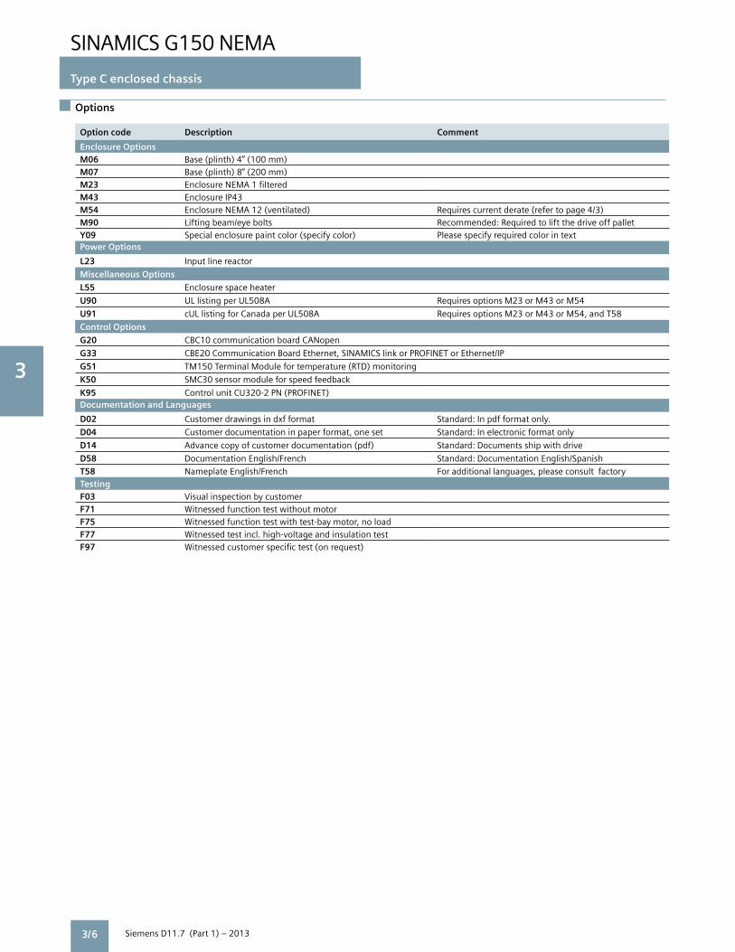
Enclosure OptionsM06 Base (plinth) 4” (100 mm)M07 Base (plinth) 8” (200 mm)M23 Enclosure NEMA 1 filteredM43 Enclosure IP43M54 Enclosure NEMA 12 (ventilated) Requires current derate (refer to page 4/3)M90 Lifting beam/eye bolts Recommended: Required to lift the drive off palletY09 Special enclosure paint color (specify color) Please specify required color in textPower Options
L23 Input line reactor
Miscellaneous Options
L55 Enclosure space heater
U90 UL listing per UL508A Requires options M23 or M43 or M54
U91 cUL listing for Canada per UL508A Requires options M23 or M43 or M54, and T58
Control Options
G20 CBC10 communication board CANopen
G33 CBE20 Communication Board Ethernet, SINAMICS link or PROFINET or Ethernet/IP
G51 TM150 Terminal Module for temperature (RTD) monitoring
K50 SMC30 sensor module for speed feedback
K95 Control unit CU320-2 PN (PROFINET)Documentation and Languages
D02 Customer drawings in dxf format Standard: In pdf format only.
D04 Customer documentation in paper format, one set Standard: In electronic format only
D14 Advance copy of customer documentation (pdf) Standard: Documents ship with drive
D58 Documentation English/French Standard: Documentation English/Spanish
T58 Nameplate English/French For additional languages, please consult factoryTestingF03 Visual inspection by customerF71 Witnessed function test without motorF75 Witnessed function test with test-bay motor, no loadF77 Witnessed test incl. high-voltage and insulation testF97 Witnessed customer specific test (on request)

SINAMICS G150 NEMA
Type C enclosed chassis
3
Siemens D11.7 (Part 1) – 2013
Options combination matrix
3/7
The following tables provide an overview of which standard options can be combined with each other, and which cannot. Please refer to the descriptions of options for more information. Custom configurations may be possible to provide combinations not available as standard – please contact the factory. Mechanical and miscellaneous options
M06 M07 M23 M43 M54 M90 U90 U91
M06 –
M07 –
M23 – –
M43 – –
M54 – –
M90
U90 –
U91 –
Electrical options
3 Possible combination
– Combination not available as standard
G20 G33 K50 L23 L55
G20 –
G33 –
K50
L23
L55

SINAMICS G150 NEMA
Type C enclosed chassis
3
Siemens D11.7 (Part 1) – 2013
Description of options
3/8
Standard documentationCustomer drawings supplied with the new SINAMICS G150 NEMA are always job specific (showing the configuration actually supplied, options not provided are not shown).
All customer documentation is provided in electronic format on a CD, which ships inside the drive. All documents are in pdf format (Adobe Acrobat) and are supplied in English and a copy in Spanish. In addition, a paper copy of the Safety and Transportation Guidelines and the Installation Check List are included too.
D02 Customer drawings in dxf formatSchematics, outline dimension and layout drawings will be provided in AutoCAD (dxf) on the CD (or as specified by other option codes).
D04Customer documentation in paper format, one setA paper copy of customer drawings, spare parts list and test certificate is shipped with the drive. For multiple copies, add option code to order no. multiple times (once for each set).
D14Advance copy of customer documentation (pdf)To receive a copy of customer drawings earlier than with drive shipment, i.e. after order placement (typically within 2 weeks). If option codes D02 and/or D04 are specified, the advance copy of the drawings will be supplied in dxf format and/or paper too.
D58Documentation English/FrenchTwo copies of the documentation (drawings and manuals) will be provided on the CD (or as specified by other option codes), one in English and the other in French.
F03, F71, F75, F77, F97Witnessed (or observed) testing
Order Descriptioncode
F03 Visual inspection The scope of the inspection comprises: by customer • Checking the enclosure type • Checking the equipment (components) • Checking the equipment identifiers • Checking the clearance and creepage distances • Checking the wires • Checking the customer documentation • Submitting the acceptance report
The checks are carried out with the drive deenergized.
F71 Witnessed The scope of the witnessed test function test of comprises: drive without • Visual inspection as per option F03 motor • Check of power supply • Check of protective and monitoring devices (simulation) • Check of fans • Precharging test • Functional test without connected motor • Submitting the acceptance report
After the visual inspection with the drive switched off, the drive is connected to rated voltage. No current flows at the drive output.
F75 Witnessed function The scope of the witnessed test comprises: test with test-bay • Visual inspection as per option F03 motor, no load • Check of power supply • Check of protective and monitoring devices (simulation) • Check of fans • Precharging test • Functional test with test bay motor (no load) • Submitting the acceptance report
After the visual inspection with the drive switched off, the drive is connected to rated voltage. A small current flows at the drive output to power the test bay motor (no load).
F77 Witnessed test incl. The scope of the acceptance comprises: high-voltage and • High-voltage test insulation test • Measurement of insulation resistance
F97 Witnessed customer If additional witnessed testing is desired specific drive over and above options F03 to F71, acceptance please provide a specification/test plan inspections/tests for the factory to submit a quotation. (on request)

SINAMICS G150 NEMA
Type C enclosed chassis
3
Siemens D11.7 (Part 1) – 2013 3/9
Description of options
G20CBC10 communication board CANopenThe CBC10 Communication Board is used to interface the CU320-2 Control Unit of the SINAMICS G150 to the CAN (Controller Area Network) protocol. The board’s driver software fulfills the standards of the following CANopen specification of the CiA organization (CAN in Automation):• Communication profiles in accordance with DS 301• Drive profile in accordance with DSP 402 (in this case Pro file Velocity Mode)• EDS (Electronic Data Sheet) in accordance with DSP 306• Operating status signaling in accordance with DSP 305 The CBC10 Communication Board plugs into the option slot on the CU320-2 Control Unit. The CAN interface on the CBC10 has 2 SUB-D connections for input and output.
G33CBE20 communication board EthernetThe CBE20 communication board connects the CU320-2 DP or CU320-2 PN Control Unit to an additional communications bus. The CBE20 can be parameterized to connect to either:• SINAMICS Link high speed peer-to-peer communications with other CBE20 modules plugged into the CU320-2 control units of other SINAMICS drives, up to 64 nodes.• PROFINET I/O network, 100 Mbit/s full-duplex, supports real-time classes RT (Real-Time) and IRT (Isochronous Real-Time). (Only one communication interface can be used in isochronous operation when operating the CBE20 in a CU320-2 DP or PN Control Unit).• EtherNet/IP (EtherNet Industrial Protocol) is an open standard predominantly used in the automation industry. EtherNet/IP is supported by the Open DeviceNet Vendor Association (ODVA).
In addition, the CBE20 allows on a PROFINET or EtherNet/IP network:• Standard Ethernet TCP/IP communication for engineering processes using the STARTER commissioning tool
The CBE20 Communication Board plugs into the option slot on the CU320-2 Control Unit. It has 4x RJ45 Ethernet ports.
Description of the CBE20 Communication Board Ethernet Chapter 4.
G51 TM150 Terminal Module (RTD Monitoring)The TM150 RTD module is suitable for monitoring temperature sensors type Pt100 or Pt1000 (Platinum RTD 100 ohm or 1,000 ohm), KTY84, PTC thermistor or a temperature switch contact (NC). Up to 12 sensors in 2-wire connection or up to 6 sensors in 3- or 4-wire connection can be connected to one TM150. Temperature values from the TM150 are available for further processing, for transmission to the process control system via bus communications and can be displayed on the AOP30.Note: TM150 inputs are not electrically isolated. Only temperature sensors isolated per IEC 61800-5-1 may be connected to terminals “+Temp” and “-Temp”. Failure to observe these instructions can result in electric shock!
K50SMC30 sensor module for speed feedbackThe SMC30 encoder module is required to connect a speed feedback encoder to the drive. Rotary pulse encoder signals are converted here and made available for evaluation via the DRIVE-CLiQ interface of the controller.
The following encoders are supported by the SMC30:• TTL encoders• HTL encoders
The motor temperature can also be detected using a KTY84-130 sensor or PTC thermistors.
Refer to engineering information for details. K95CU320-2 PN Control Unit Replace the standard CU320-2 DP with PROFIBUS port by the CU320-2 PN with PROFINET port. L23Input line reactorThis option is to include an input line reactor inside the enclosure. Alternatively the line reactor can be mounted externally. A minimum 2% input line reactor is recommended for most installations.
If the drive is powered via a separate transformer, or if the ratio between the line short circuit capacity at the point of connection and the rated drive output is low, the input line reactor may be omitted.
A 2% to 3% inductor primarily assures the minimum current form factor, protects the drive against excessive harmonic currents and thus overloads, and improves the sensitivity of the VFD to voltage spikes.
L55Enclosure space heaterSpace heaters are recommended at low ambient temperatures and high levels of humidity to prevent condensation. One 90 W heater is provided for each cabinet <32” (800 mm) width. For cabinets exceeding this width, two heaters will be installed.
M06Base (plinth) 4” (100 mm) highThe 4” enclosure base allows larger bending radii for cables (cable entry from below) and routing them within the base. It is delivered already mounted to the enclosure. The height of the operator panel changes accordingly. The base is always colored RAL 7022 (umbra grey). A special color is not possible. Enclosure with option M06

SINAMICS G150 NEMA
Type C enclosed chassis
3
Siemens D11.7 (Part 1) – 2013
M07Base (plinth) 8” (200 mm) highThe 8” enclosure base provides more space for bending and routing cables. The base is delivered already mounted to the enclosure. The height of the operator panel changes accordingly.
The base color is the same as the enclosure, RAL 7035 (light grey). If the enclosure is ordered in a special color (option Y09), the 8” base is also painted the same color. M23Enclosure NEMA 1 filteredLouvers and foam air filters are added to air inlet and outlet openings (IP23). A NEMA 1 filtered enclosure is required to meet the requirements for listing the enclosed drive per UL508A.
M43Enclosure IP43Similar to NEMA 1 filtered (M23), but additionally a 1mm wire mesh is provided behind the air filters.
M54Enclosure NEMA 12 (ventilated) Louvers and fine paper air filters are added to air inlet and outlet openings (IP54), to prevent even fine dust particles from entering the enclosure in very dusty environments. These fine dust filters are a patented design for high volume airflow with small derating. The drive current must be derated to 95% with a NEMA 12 filtered enclosure.
M90Lifting beam/eye boltsNote: Option M90 is strongly recommended, to enable lifting the drives off their pallet safely.
For single cabinets up to a width of 24” (600 mm), eye bolts are provided. For larger enclosures transportation beams are provided.
Once the drives are in position, the lifting hardware needs to be removed to mount the tophats. For multiple drives with identical enclosure sizes, option M90 can be ordered once and the hardware re-used for other units.
U90UL listing per UL508A The drive is provided with the UL listing mark per UL508A (UL file number E83449).
UL listing mark
The basis for UL listing is the maximum continuous output current rating of the drive. For a specific duty cycle rating (light overload/VT or high overload/CT) the respective base load current may not in all instances be in line with the current rating per NEC table 430-150. Note UL listing requires air filters (options M23 or M43 or M54).
U91cUL listing for Canada per UL508A The drive is provided with the cUL listing mark for Canada per UL508A (UL file number E83449).
Note cUL listing requires air filters (options M23 or M43 or M54), and English/French nameplate (T58).
Y09Special enclosure paint color (specify color)The standard color of the drive enclosures is RAL 7035 (light grey). The special color must be specified in plain text when ordering.
In general, colors available as powder coating can be ordered. Please consult factory to confirm. The enclosure, tophats and, if specified, 8” high plinths (option M07) will be supplied in the specified special color.
Note: 1. The molded plastic parts (e.g. louvers) are colored RAL 7035 and cannot be painted. 2. 4” plinths are always colored RAL 7022 (umber grey).3. Cabinet frames and interiors are always colored RAL 7035.
SINAMICS G150 type C with eye bolts
Description of options
3/10

SINAMICS G150 NEMA
Type C enclosed chassis
3
Siemens D11.7 (Part 1) – 2013 3/11
Line side components for SINAMICS G150 NEMA type C enclosed chassis
SINAMICS G10 NEMA type C enclosed chassis do not include any line side components (except for the optional line reactor) – these components need to be added externally, for example in an MCC.
To obtain the drive SCCR (short circuit current ratings) shown in the technical data, it is necessary to combine it with the fuses and fuse bases listed in the manual, and shown in the table below (substitutes are not permitted). Also, a UL-listed
circuit breaker for motor branch circuit protection (withminimum SCCR as required for the drive) is required, which may not exceed the maximum current rating shown.
The SCCR shown below is the value applicable to the drive when combined with the specified fuses, and the recommended circuit breaker and, if applicable, recommended contactor (used as input, output and/or bypass contactor).
SINAMICS G150NEMA Type CEnclosed chassis
Output(light overload) at 460 V or 575 V, 60 Hz
Circuit breaker Semiconductor fuses Contactor
max. rating
Recommendedpart #
SCCR max.1)
Fuse requiredpart #
Fuse baserequiredpart #
Recommendedpart #
SCCRmax 1) 2)
Model No. HP A kA per phase per phase Siemens kA
Supply voltage 380 V to 480 V 3 ph. AC
6SL3710-1GE32-1CU3 150 500 HJX3B300 65 3NE12302 3NH3320 3RT10666AF36 65
6SL3710-1GE32-6CU3 200 600 HJX3B400 65 3NE13312 3NH3320 3RT10766AF36 65
6SL3710-1GE33-1CU3 250 700 HLX3B500 65 3NE13342 3NH3420 3RT10766AF36 65
6SL3710-1GE33-8CU3 300 800 HLX3B600 65 3NE13342 3NH3420 3RT10766AF36 65
6SL3710-1GE35-0CU3 400 1200 HMX3B800 65 3NE14362 3NH3420 3RT10766AF36 65
6SL3710-1GE36-1CU3 500 1200 HMX3B800 65 3NE14382 3NH3420 40NH32AF 65
6SL3710-1GE37-5CU3 600 1600 HNX3X100 65 3NE14482 3NH3420 40NH32AF 65
6SL3710-1GE38-4CU3 700 2000 HNX3X120 65 2x 3NE14362 2x 3NH3420 40PH32AF 65
6SL3710-1GE41-0CU3 800 2000 HPX3X160 65 2x 3NE14372 2x 3NH3420 40PH32AF 65
Supply voltage 500 V to 600 V 3 ph. AC
6SL3710-1GF31-8CU3 150 400 HJX3B300 25 3NE12272 3NH3320 3RT10666AF36 25
6SL3710-1GF32-2CU3 200 500 HJX3B350 25 3NE12302 3NH3320 3RT10666AF36 25
6SL3710-1GF32-6CU3 250 600 HJX3B350 25 3NE13312 3NH3320 3RT10666AF36 25
6SL3710-1GF33-3CU3 300 800 HLX3B500 25 3NE13342 3NH3420 3RT10766AF36 25
6SL3710-1GF34-1CU3 400 1000 HLX3B600 25 3NE13342 3NH3420 3RT10766AF36 25
6SL3710-1GF34-7CU3 450 1000 HMX3B800 35 3NE14352 3NH3420 3RT10766AF36 30
6SL3710-1GF35-8CU3 600 1200 HMX3B800 35 3NE14472 3NH3420 40NH32AF 35
6SL3710-1GF37-4CU3 700 1600 HNX3X100 35 3NE14482 3NH3420 40PH32AF 35
6SL3710-1GF38-1CU3 800 2000 HNX3X120 35 2x 3NE13342 2x 3NH3420 40PH32AF 35
1) The short circuit current ratings (SCCR) listed above are the SCCR for the enclosed drive unit when used with the recommended components.2) The SCCR listed for the contactor is the combination SCCR when the contactor is used in combination with the recommended circuit breaker.3) The circuit breaker part # is for the circuit breaker frame only, and does not include any accessories required for connection (for example lugs).
NOTE: SCCR ratings are provided for information only, and are based on published catalog data at the time this catalog was written. Since the data may be revised, please check for accuracy against the most current catalogs and/or manuals, and/or the device nameplates.

SINAMICS G150 NEMA
Type C enclosed chassis
3
Siemens D11.7 (Part 1) – 20133/12
Line side components for SINAMICS G150 NEMA type C enclosed chassis
Input line reactorA minimum 2% input line reactor is recommended for most installations. It can be included in the enclosure of the enclosed chassis (option L23) or alternatively be mounted externally, for example in an MCC with the other line side components. The recommended type of input line reactor is listed below.
A 2% to 3% inductor primarily assures the minimum current form factor, protects the drive against excessive harmonic currents and thus overloads, and improves the sensitivity of the VFD to voltage spikes. If the drive is powered via a separate transformer, or if the ratio between the line short circuit capacity at the point of connection and the rated drive output is low, the input line reactor may be omitted.
SINAMICS G150NEMA Type CEnclosed chassis
Output(light overload)at 460V or 575V, 60 Hz
Input line reactor Motor (output) reactor dV/dt filter plus VPL
Recommendedpart #
Recommendedpart #
Recommendedpart #
Model No. HP
Supply voltage 380 V to 480 V 3 ph. AC
6SL3710-1GE32-1CU3 150 6SL30000CE323AA0 6SL30002BE321AA0 6SL30002DE326AA0
6SL3710-1GE32-6CU3 200 6SL30000CE328AA0 6SL30002BE326AA0 6SL30002DE326AA0
6SL3710-1GE33-1CU3 250 6SL30000CE333AA0 6SL30002BE332AA0 6SL30002DE350AA0
6SL3710-1GE33-8CU3 300 6SL30000CE351AA0 6SL30002BE338AA0 6SL30002DE350AA0
6SL3710-1GE35-0CU3 400 6SL30000CE351AA0 6SL30002BE350AA0 6SL30002DE350AA0
6SL3710-1GE36-1CU3 500 6SL30000CE363AA0 6SL30002AE361AA0 6SL30002DE384AA0
6SL3710-1GE37-5CU3 600 6SL30000CE377AA0 6SL30002AE384AA0 6SL30002DE384AA0
6SL3710-1GE38-4CU3 700 6SL30000CE387AA0 6SL30002AE384AA0 6SL30002DE384AA0
6SL3710-1GE41-0CU3 800 6SL30000CE410AA0 6SL30002AE410AA0 6SL30002DE414AA0
Supply voltage 500 V to 600 V 3 ph. AC
6SL3710-1GF31-8CU3 150 6SL30000CH322AA0 6SL30002AH318AA0 6SL30002DH322AA0
6SL3710-1GF32-2CU3 200 6SL30000CH322AA0 6SL30002AH324AA0 6SL30002DH322AA0
6SL3710-1GF32-6CU3 250 6SL30000CH327AA0 6SL30002AH326AA0 6SL30002DH333AA0
6SL3710-1GF33-3CU3 300 6SL30000CH334AA0 6SL30002AH336AA0 6SL30002DH333AA0
6SL3710-1GF34-1CU3 400 6SL30000CH348AA0 6SL30002AH345AA0 6SL30002DH341AA0
6SL3710-1GF34-7CU3 450 6SL30000CH348AA0 6SL30002AH347AA0 6SL30002DH358AA0
6SL3710-1GF35-8CU3 600 6SL30000CH360AA0 6SL30002AH358AA0 6SL30002DH358AA0
6SL3710-1GF37-4CU3 700 6SL30000CH384AA0 6SL30002AH381AA0 6SL30002DH381AA0
6SL3710-1GF38-1CU3 800 6SL30000CH384AA0 6SL30002AH381AA0 6SL30002DH381AA0
Motor reactor (output reactor)Motor reactors reduce the voltage load on the motor windings by reducing the voltage gradients (dV/dt) generated by the drive at the motor terminals. (Note that a motor reactor does not increase the maximum motor cable length for SINAMICS G150).
Output dV/dt-Filter plus VPL (Voltage Peak Limiter) The dV/dt filter plus VPL allows the connection of non-inverter duty motors to the SINAMICS G150 drive. For motors insulated per NEMA MG1, part 30 (voltage peaks
<1,000 V and dV/dt <500 V/µs) the maximum allowablemotor cable length is up to 980’ (300 m) for a supply voltage of 380-480 V, and 490’ (150 m) for 500-600 V. Note that longer cable lengths of up to 450 m are possible, but voltage peaks may exceed 1,000 V. Please refer to engineering information for additional details.
The dv/dt filter plus VPL consists of two components: the dv/dt reactor and the VPL (Voltage Peak Limiter), which limits voltage peaks and returns the energy to the DC link.

Siemens D11.7 (Part 1) – 2013
5 1
SINAMICS G150 NEMAEngineering information 4
4/2 Technical data Electrical and mechanical data Compliance with standards Ambient conditions Mechanical stability
4/3 Derating data Current derating due to altitude and temperature Voltage derating due to altitude Current derating due to pulse frequency
4/5 Motor and drive sizing, overloads Dimensioning of drives Motor and drive sizing Overload capability
4/6 Input and output reactors and filters, harmonics, motor design Input line reactor Harmonic feedback Motor cable lengths Motor design Output reactor and dV/dt filter
4/7 Operator panel
4/8 Control interfaces, Firmware functions
4/9 Control unit and accessories Bus communications 4/10 CBE20 Communication Board EtherNet
4/11 Digital/analog inputs and outputs
4/12 RTD monitor
4/13 Speed encoder interface 4/14 Safety integrated functions
4/22 Safe Terminal Module TM54F
4/22 Safe Brake Adapter
4/23 Braking Units
4/25 STARTER commissioning tool
4/26 Drive Control Chart (DCC)
4/27 Service and support

SINAMICS G150 NEMA
Engineering information
4
Siemens D11.7 (Part 1) – 2013
Technical data
4/2
Electrical data Supply voltages and output ranges 380 V to 480 V 3 ph AC, ±10% (-15% < 1 min) 150 to 800 HP 500 V to 600 V 3 ph AC, ±10% (-15% < 1 min) 150 to 800 HP
Supply systems Grounded (TN/TT) supplies or ungrounded (IT) supplies
Line frequency 47 Hz to 63 Hz
Output frequency 0 Hz to 300 Hz
Power factor fundamental / total >0.96 / 0.75 ... 0.93
Converter efficiency > 98%
Control method Vector control (sensorless & closed loop) or V/Hz control
Fixed speeds 15 fixed speeds plus 1 minimum speed, programmable (in the default setting 3 fixed setpoints plus 1 minimum speed can be selected via digital inputs or bus communications)
Skipped frequency ranges 4, programmable
Setpoint resolution 0.001 rpm digital / 12 bit analog
Braking operation optional via braking unit
Mechanical data
Type of enclosure NEMA1 (optionally NEMA 1 filtered or NEMA 12 ventilated)
Enclosure details Rittal TS8, doors with double bit lock and 3-point latch, three section base plates for cable entry
Enclosure color RAL 7035 light grey, indoor installation
Type of cooling Forced air ventilation
Noise level LpA (1 m) < 75 dB at 60 Hz line frequency
Environmental protection Nickel plated busbars, varnish coated electronic boards
Compliance with standards
Standards NEMA ICS 7, NEMA ICS 7.1, NEMA 250, NFPA79, UL508C for power module, ISO 13849-1, IEC 60146-1-1, IEC 60204-1, IEC 60529, IEC 60508-1, IEC 61800-2, IEC 61800-3, IEC61800-5-1, IEC 61800-5-2
UL listing Optional listing per UL508A
CE marking In accordance with EMC directive No. 2004/108/EC and low-voltage directive No. 2006/95/EC
EMC conformance EMC conformance is compliant with the EMC product standard for variable-speed drives IEC 61800-3 for the “Second environment”, category C3 (industrial supply systems).
The equipment is not designed for connection to the “First environment” (public/ residential supply systems) and may cause electromagnetic interference on a public system.
Ambient conditions Operation Storage Transport
Ambient temperature 32°F to 104°F (0 °C to +40 °C) -13°F (-25 °C) to 131°F -13°F (-25 °C) to 158°F (+70 °C)
Up to +122°F (+50°C) with derating (+55 ºC) Above -40°F (-40 °C) for 24 hours
Relative humidity (non-condensing) 5% to 95% 5% to 95% 5% to 95% at 40 ºC
Class 3K3 to IEC 60721-3-3 Class 1K4 to IEC 60721-3-1 Class 2K3 to IEC 60721-3-2
Environmental class/harmful Class 3C2 to IEC 60721-3-3 Class 1C2 to IEC 60721-3-1 Class 2C2 to IEC 60721-3-2 chemical substances
Organic/biological influences Class 3B1 to IEC 60721-3-3 Class 1B1 to IEC 60721-3-1 Class 2B1 to IEC 60721-3-2
Installation altitude Up to 6,600 ft (2000 m) above sea level without reduction in performance, > 6,600 ft see derating data
Mechanical stability Operation Storage Transport Vibratory load
- Deflection 0.075 mm at 10 Hz to 58 Hz 1.5 mm at 5 Hz to 9 Hz 3.1 mm at 5 Hz to 9 Hz
- Acceleration 10 m/s2 at > 58 Hz to 200 Hz 5 m/s2 at > 9 Hz to 200 Hz 10 m/s2 at > 9 Hz to 200 Hz
– Class 1M2 to IEC 60721-3-1 Class 2M2 to IEC 60721-3-2
Shock load
- Acceleration 100 m/s2 at 11 ms 40 m/s2 at 22 ms 100 m/s2 at 11 ms
Class 3M4 to IEC 60721-3-3 Class 1M2 to IEC 60721-3-1 Class 2M2 to IEC 60721-3-2
Deviations from the defined classes are identified by underlining.

SINAMICS G150 NEMA
Engineering information
4
Siemens D11.7 (Part 1) – 2013 4/3
Derating data
Current derating as a function of the installation altitude and ambient temperature If SINAMICS G150 drives are operated at an installation altitude >6,600 ft (2,000 m) above sea level, the maximumpermissible output current can be calculated using the following tables. Note that the enclosure type selected for the drive must also be taken into account.
Installation altitude above sea level
Current derating at an ambient temperature of
68°F(20°C)
77°F(25°C)
86°F(30°C)
95°F(35°C)
104°F(40°C)
113°F(45°C)
122°F(50°C)
0 to 6,600 ft (0 to 2,000 m) 93.3 % 86.7 %
up to 8,250 ft (up to 2,500m) 100% 96.3%
up to 9,900 ft (up to 3,000 m) 98.7%
up to 11,550 ft (up to 3,500 m) 96.3%
up to 13,200 ft (up to 4,000 m) 97.5%
Installation altitude above sea level
Current derating at an ambient temperature of
68°F(20°C)
77°F(25°C)
86°F(30°C)
95°F(35°C)
104°F(40°C)
113°F(45°C)
122°F(50°C)
0 to 6,600 ft (0 to 2,000 m) 93.3% 86.7% 80.0%
up to 8,250 ft (up to 2,500m) 100% 96.3% 89.8%
up to 9,900 ft (up to 3,000 m) 98.7% 92.5%
up to 11,550 ft (up to 3,500 m) 94.7%
up to 13,200 ft (up to 4,000 m) 96.3% 90.7%
NEMA 12 ventilated (IP54) enclosure:Current derating as a function of the ambient (inlet air) temperature and installation altitude.
NEMA 1 (IP21), NEMA 1 filtered (IP23) or IP43 enclosure: Current derating as a function of the ambient (inlet air) temperature and installation altitude
Installation altitude above sea level
Max. nominal input voltage 1)
for a rated drive voltage of
380 - 480V 500 - 600V
0 to 6,600 ft (0 to 2,000 m) 480 600
up to 7,450 ft (up to 2,250 m) 466 600
up to 8,250 ft (up to 2,500 m) 451 600
up to 9,100 ft (up to 2,750 m) 437 600
up to 9,900 ft (up to 3,000 m) 423 600
up to 10,750 ft (up to 3,250 m) 408 581
up to 11,550 ft (up to 3,500 m) 394 562
up to 12,400 ft (up to 3,750 m) 379 542
up to 13,200 ft (up to 4,000 m) 365 523
1) Nominal voltage with tolerance ±10%.
Voltage derating due to altitude is not required if an isolation transformer is installed upstream of and in close proximity to the drive as this reduces transient overvoltages in accordance with IEC 61800-5-1. Please refer to the SINAMICS Engineering Manual for details of the requirements applicable to the isolation transformer. If these requirements are not met, then the supply voltage must be reduced in accordance with the following table.
Voltage derating as a function of the installation altitudeIn addition to current derating, voltage derating may also need to be applied at installation altitudes >6,600 ft (2,000 m) above sea level.

SINAMICS G150 NEMA
Engineering information
4
Siemens D11.7 (Part 1) – 2013
Derating data
4/4
Current derating as a function of the pulse frequencyIf the drive is set to operate at increased pulse frequencies, the output current values listed in the technical specifications must be derated in accordance with the tables below.
(Note that SINAMICS G150 can be set up to operate athigher pulse frequencies when permitted by ambient and load conditions, and automatically lower the pulse frequency to avoid overtemperature – in this case derating is not necessary).
Order no. Output (light overload) at 460 V or 575 V, 60 Hz
Rated output current at 2 kHz
Derating factor at 4 kHz
HP A
Supply voltage 380 V to 480 V 3 ph. AC
6SL3710-1GE32-1_U3 150 210 82 %
6SL3710-1GE32-6_U3 200 260 83 %
6SL3710-1GE33-1_U3 250 310 88 %
6SL3710-1GE33-8_U3 300 380 87 %
6SL3710-1GE35-0_U3 400 490 78 %
Derating factor of the output current as a function of the pulse frequency for devices with a rated pulse frequency of 2 kHz
Derating factor of the output current as a function of the pulse frequency for devices with a rated pulse frequency of 1.25 kHz
Order no. Output (light overload) at 460 V or 575 V, 60 Hz
Rated output current at 1.25 kHz
Derating factor at 2.5 kHz
Derating factor at 5 kHz
HP A
Supply voltage 380 V to 480 V 3 ph. AC
6SL3710-1GE36-1_U3 500 605 72 % 60 %
6SL3710-1GE37-5_U3 600 745 72 % 60 %
6SL3710-1GE38-4_U3 700 840 79 % 60 %
6SL3710-1GE41-0_U3 800 985 87 % 60 %
Supply voltage 500 V to 600 V 3 ph. AC
6SL3710-1GF31-8_U3 150 175 87 % 60 %
6SL3710-1GF32-2_U3 200 215 87 % 60 %
6SL3710-1GF32-6_U3 250 260 88 % 60 %
6SL3710-1GF33-3_U3 300 330 82 % 55 %
6SL3710-1GF34-1_U3 400 410 82 % 55 %
6SL3710-1GF34-7_U3 450 465 87 % 55 %
6SL3710-1GF35-8_U3 600 575 85 % 55 %
6SL3710-1GF37-4_U3 700 735 79 % 55 %
6SL3710-1GF38-1_U3 800 810 72 % 55 %
Calculating derating factor by means of linear interpolation.
For intermediate values of pulse frequencies, the relevant derating factors can be determined by means of linear interpolation.
The following formula applies to this: Y2 = Y0 +
Y1 – Y0 (X2 – X0 ) X1 – X 0
Example:The derating factor is required for when X2 = 2 kHz for 6SL3710-1GE41-0_U0.X0 = 1.25 kHz, Y0 = 100% X1, = 2.5 kHz, Y1 = 87%, X2 = 2 kHz, Y2 = ??
Y2 = 100% +
87% – 100% (2 kHz – 1,25 kHz) = 2.5 kHz - 1,25 kHz
100% + -13 % (0,75 kHz) = 100 % – 7,8 % = 92.2 % 1,25 kHz
Derating factor
100%??%
75%
50%
25%
1,25 kHz 2 kHz 2.5 kHz 5 kHz fPulse
87%
60%
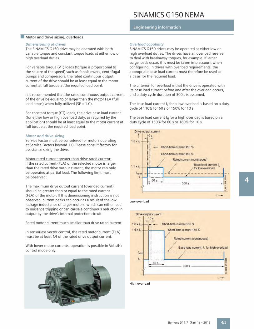
SINAMICS G150 NEMA
Engineering information
4
Siemens D11.7 (Part 1) – 2013 4/5
Motor and drive sizing, overloads
Dimensioning of drivesThe SINAMICS G150 drive may be operated with both variable torque and constant torque loads at either low or high overload duties.
For variable torque (VT) loads (torque is proportional to the square of the speed) such as fans/blowers, centrifugal pumps and compressors, the rated continuous output current of the drive should be at least equal to the motor current at full torque at the required load point.
It is recommended that the rated continuous output current of the drive be equal to or larger than the motor FLA (full load amps) when fully utilized (SF = 1.0).
For constant torque (CT) loads, the drive base load current (for either low or high overload duty, as required by the application) should be at least equal to the motor current at full torque at the required load point.
Motor and drive sizingService Factor must be considered for motors operating at Service Factors beyond 1.0. Please consult factory for assistance sizing the drive.
Motor rated current greater than drive rated current:If the rated current (FLA) of the selected motor is larger than the rated drive output current, the motor can only be operated at partial load. The following limit must be observed:
The maximum drive output current (overload current) should be greater than or equal to the rated current (FLA) of the motor. If this dimensioning instruction is not observed, current peaks can occur as a result of the low leakage inductance of larger motors, which can either lead to nuisance tripping or can cause a continuous reduction in output by the drive’s internal protection circuit.
Rated motor current much smaller than drive rated current:
In sensorless vector control, the rated motor current (FLA) must be at least 1⁄4 of the rated drive output current.
With lower motor currents, operation is possible in Volts/Hz control mode only.
Overload capabilitySINAMICS G150 drives may be operated at either low or high overload duties. The drives have an overload reserve to deal with breakaway torques, for example. If larger surge loads occur, this must be taken into account when configuring. In drives with overload requirements, the appropriate base load current must therefore be used as a basis for the required load.
The criterion for overload is that the drive is operated with its base load current before and after the overload occurs, and a duty cycle duration of 300 s is assumed.
The base load current IL for a low overload is based on a duty cycle of 110% for 60 s or 150% for 10 s.
The base load current IH for a high overload is based on a duty cycle of 150% for 60 s or 160% for 10 s.
Low overload
High overload

SINAMICS G150 NEMA
Engineering information
4
Siemens D11.7 (Part 1) – 2013
and generally do not require the drive to be fitted with an output reactor or filter.
Non-inverter duty motorsMotors designed for across the line operation may have an insulation system per NEMA MG1, part 30 (voltage peaks of up to 1,000 V with rise times of 2 or more microseconds). Operating such a motor on a VFD requires the use of an output filter, to ensure long term reliable operation and avoid premature insulation failure.
Motor (output) reactor (option L08)An output reactor limits the rate of rise of voltage (dV/dt) and helps to avoid damaging bearing currents. An output reactor does not reduce the magnitude of voltage peaks, irrespective of cable length. A motor reactor is therefore generally not adequate for operating non-inverter duty motors on drives.
dV/dt filter with VPL (option L10)The dV/dt filter plus VPL (Voltage Peak Limiter) allows the connection of non-inverter duty motors to the SINAMICS G150 drive, by limiting the voltage rate of rise dV/dt to <500 V/µs and voltage peaks as follows:
Max. pulse and output frequencies (options L08 & L10)The maximum pulse frequency and output frequency for SINAMICS G150 with output reactor (option L08) or dV/dt filter (option L10) are:
Recommended practiceFor maximum reliability and equipment life when operating a motor on a VFD, use:• An inverter duty motor per NEMA MG1, part 31 with insulated non-drive end bearing or shaft grounding brush• A dV/dt filter for a non-inverter duty motor• Motor cables with a symmetrical design, screened to minimize EMC issues (PE = ground wire)
•Grounding wires with low impedance across a large frequency range (DC to 70 MHz) such as braided copper, terminated with the largest possible surface area• Separate ground wires connected directly between motor and drive, and between motor and driven machine
Input and output reactors and filters, harmonics, motor design
4/6
Input line reactorsAn input line reactor reduces the level of harmonic distortion injected on the line, and reduces the sensitivity of the VFD to voltage spikes in the network, serving as a buffer against rapid rises of current from the line to the DC link.
A 2% or 3% inductor primarily assures the minimum current form factor, and improves the sensitivity of the VFD to voltage spikes. A minimum 2% input line reactor is recommended unless the drive is powered via a separate drive isolation transformer, or if the ratio between the line short circuit capacity at the point of connection and the rated drive output is low (i.e. the source impedance is sufficiently high).
Harmonic feedback to the supply systemSINAMICS G150 drives have a 6-pulse front end. In some instances additional harmonic mitigation may be required to meet the requirements of IEEE 519-1992, depending on the location of the PCC (point of common coupling), the power supply system and other loads.
Calculations will determine the extent to which the requirements of IEEE 519-1992 are or are not met. Such calculations require details of the supply system (short circuit capacity at the PCC) and details of other loads (maximum demand, linear and non-linear (drive or converter) loads).
Motor cable lengthsThe cable capacitance of long motor cables causes high charging currents, and the drives’ ability to cope with these charging currents may require limits on cable length, and in some cases the use of an output reactor. SINAMICS G150 technology allows much longer motor cable lengths without output reactor than older generation products.
Maximum motor cable lengths for SINAMICS G150 without or with output reactor (option L08) or dV/dt filter (option L10) are:Unshielded cable: 1,480 ft (450 m)Shielded cable: 980 ft (300 m)If longer cable lengths are required, please consult factory.
Motor designThe switching of IGBTs results in high rates of rise of voltage (dV/dt) and voltage spikes of up to twice the DC bus voltage at the motor terminals due to reflections in the cable. Note that the critical cable length at which voltage doubling occurs reduces with motor size; for high ratings (150 HP and up) the critical cable length can be well below 50 ft. For higher HP drives like SINAMICS G150, the motor cable length is therefore not a significant factor when considering the stresses applied to the motor due to voltage rate of rise and peaks.
Inverter duty motorsInverter duty motors have an insulation system per NEMA MG1, part 31 (peaks of 3.1 times rated voltage with risetimes rated voltage with the rated voltage with rise times of 0.1 or more microsecond). They are designed for the dV/dt and voltage spikes expected with operation on PWM drives,
L1
L2L3
L1
L2L3
L1
L2L3PE PE
PE PE
ConcentricCu or Al screen
Steel reinforcement G_D
011_
EN
_000
65
Rated Approx. peak voltagevoltage for motor cable length of 490’ (150 m) 980’ (300 m) 1480‘ (450 m)380 – 480 V <1,000 V <1,000 V <1,200 V500 – 600 V <1,000 V <1,200 V 1,300 V
Rated Max. pulse Max. outputoutput frequency frequency150 – 400 HP @ 380 – 480 V 4 kHz 150 HzAll other ratings 2.5 kHz 150 Hz

SINAMICS G150 NEMA
Engineering information
4
Siemens D11.7 (Part 1) – 2013
(3 : Vector) Current fault in
F 07901 Motor overspeed
Help Alt Back Ack.
G_D
011_
en_0
0050
G_D
011_
e n_0
0051
Motor overspeed Fault val = 000000007 00000007 (hex) Cause: The maximum permisible positive or negative speed has been exceeded. The maximum permissile positive speed is calculated as follows: Back
Motor dataBackp0304 MOT.U_rated 400.0 Vp0305 MOT. I_rated 405.0 Ap0307 MOT.P_rated 235.0 kWp0308 MOT.CosPhi_ rated 0.870
Help Change OK
G_D
011_
en_0
0048
G_D
011_
en_0
0049
Basic commissioningBack p0700 Pre-assignment BI S/G150 TM 32 p1000 Default DI n_set TM 31 AIO p1080 Minimum speed 0.000 rpm -1 p1082 Maximum speed 1500.000 rpm -1
Help Change Further
Service / CommissioningDrive commissioning
Device commissioningAOP settingsAOP diagnosis
Help
G_D
011_
en_0
0047
Back Select.
Operation 12:25:30 Nset Fout M Pact Nact: 1450.0 rpm
1450.0048.50
2700410
rpmHzNmkW
1450.0 rpm385.3 V748
Nact
ImotVout
G_D
011_
EN
_000
11b
0% 50 100%
0% 50 100%
G_D
011_
EN
_000
12b
Operation 12:25:30 NSET 1465.50 rpm Pact 410 kW Fout 48.50 Hz Vout 385.3 V Imot 748 A Nact 1465 rpm
AOP30 advanced operator panel
The advanced operator panel is mounted in the enclosure door of the drive for operation, monitoring and commissioning tasks. The AOP30 features a graphical LCD with backlighting for plain text and bar graph display of process variables.
The AOP30’s two-stage safety concept prevents unintentional or unauthorized changes to settings. Operation of the drive from the operator panel can be disabled by a password ensuring that only parameter values and process variables can be displayed on the panel. The OFF key is factory-set to active but can also be deactivated by the customer. Another password can be used to prevent the unauthorized modification of drive parameters.
During the first start-up of the drive, the user will automatically be guided through the initial start-up procedure that allows a very simple and quick commissioning process. Only 6 motor parameters (from the motor nameplate) have to be entered when the drive is started up for the first time. The control is then optimized automatically to fine-tune the drive to the motor.
English, Spanish, French, German, Italian and Chinese are stored on the CU320-2 Control Unit’s CompactFlash card as operator panel languages. The desired language must be downloaded to the AOP30 prior to commissioning. Russian and Czech are available in addition to these standard panel languages. These can be downloaded free of charge from the Internet under the following link:http://support.automation.siemens.com/The following pictures show screen shots of the display in various operating phases, beginning with first start-up.
Only 6 motor parameters need to be entered: Output power, speed, current, power factor, voltage and frequency of the motor.
4/7
Operator panel
This information can be found on the motor nameplate, and is entered into the screens on the display by following a short, menu-driven procedure. The type of motor cooling must be entered in addition.
The next screen contains the parameter values that are used to automatically optimize the control.
During operation, current data such as setpoint and actual values is indicated on the display as absolute values in either US or international units, or in percent. Up to three process variables can be viewed as a quasi-analog bar graph.
Any alarms which occur are indicated by flashing of the yellow “ALARM” LED, while faults are signaled by a lit red “FAULT” LED. There is also an indication of the cause displayed in plain text on the display’s status line.
Alarms and faults are displayed and stored with a time stamp.

SINAMICS G150 NEMA
Engineering information
4
Siemens D11.7 (Part 1) – 2013
Control interfaces, Firmware functions
4/8
Control interfacesBoth a PROFIBUS interface on the CU320-2 DP control unit and a terminal module are provided as standard for use as the control interface.
The terminal module permits connection to the higher level control using analog and digital signals. Optionally the analog and digital inputs and outputs can be expanded by a second terminal module. Additional digital I/O on the CU320-2 control unit may be utilized too.
To simplify configuration and commissioning of the drive, the inputs and outputs are preset to factory default settings.
Open loop control and regulator functionsThe drive regulator contains a high-quality sensorless vector control with speed and current control as well as motor and drive protection.
Software and protection functionsA selection of standard software functions is described below:
Firmware functions
Setpoint input The setpoint can be defined internally or externally, internally as a fixed, motorized potentiometer or jog setpoint, externally via the PROFIBUS interface or an analog input of the terminal module. The internal fixed setpoints and the motorized potentiometer setpoint can be switched over or adjusted using control commands via all interfaces.
Motor identification Automatic motor identification permits fast and simple commissioning and optimization of the drive control.
Ramp function generator A user friendly ramp function generator with separately adjustable ramp up and ramp down times, together with variable smoothing times in the lower and upper speed ranges, improve the control response and therefore prevent mechanical overloading of the drive train. The ramp down characteristics for emergency stop can be parameterized separately.
Vdc max controller The Vdc max (DC bus) controller automatically prevents overvoltages in the DC link if, for example, the ramp-down time is set too short. This is achieved by automatically extending the ramp-down time.
Kinetic buffering During line supply failure, this functions draws power from the motor to keep the drive powered up, to the extent permitted by the kinetic energy of the drive train. The speed drops depending on the moment of inertia and torque of the load. The drive maintains control of the motor and reaccelerates it to the current speed setpoint when the power supply returns.
Automatic restart 1) The automatic restart function switches the drive on again when the power is restored after a power failure, and ramps the motor back up to the speed setpoint.
Flying restart1) The flying restart function provides bumpless connection of the drive on to a rotating motor.
Technology controller A PID controller is provided for technology control functions such as level, pressure or flow control. The P, I, and D components can be set separately. An “extended pump functions” macro offers pump specific functions including Energy Saving (hibernate), Enhanced Energy Saving, Maintenance Cleaning and Wall Deposits Prevention.
Free function blocks The freely programmable function blocks make it easy to implement logic and arithmetic functions for controlling the drive. The blocks can be programmed using either the operator panel or the STARTER commissioning tool.
Drive Control Chart Drive Control Chart (DCC) is an additional tool for the easy configuration of sophisticated process-oriented functions. (DCC) The block library contains a large selection of control, arithmetic and logic blocks as well as extensive open-loop and closed-loop control functions. The user-friendly DCC editor enables easy graphical configuration and a clear representation of control loop structures. DCC is an add-on to the STARTER commissioning tool.
Motor protection
I2t detection for The motor temperature is calculated in a motor model in the drive software, taking into account the current speed motor protection and load. More exact sensing of the temperature, also taking into account the influence of the ambient temperature, is possible by means of direct temperature monitoring using KTY84 sensors in the motor winding.
Evaluation of motor Motor protection by evaluating a KTY84 or PTC temperature sensor. When a KTY84 sensor is connected, the limit temperature values can be set for temperature alarm or trip. With a PTC thermistor, the reaction following triggering (alarm or trip) can be defined.
Motor stall protection A stalled motor (locked rotor) is recognized and the motor is protected against thermal overloading by shutting down.
Power section protection
Ground fault monitoring In grounded neutral systems a ground fault on the output side is detected by summation of phase currents, and on the output side results in shutdown.
Electronic short-circuit A short-circuit between motor and drive (on the drive output terminals, in the motor cable, in the motor terminal box) protection on the is detected and interrupted. output side
Thermal overload The temperature of the power section is monitored via a thermal model calculation that includes monitoring of heat protection sink temperature. An alarm is given when the first overtemperature threshold is reached. If the temperature rises further, either a trip is initiated or the pulse frequency or output current are automatically adjusted to reduce the thermal load until the problem is eliminated (for example, replacing blocked filter mats).
1) Factory setting: not activated (can be programmed).

SINAMICS G150 NEMA
Engineering information
4
Siemens D11.7 (Part 1) – 2013 4/9
CU320-2 Control Unit
The communication, open-loop and closed-loop control functions for the SINAMICS G150 drive are executed in the CU320-2 Control Unit.
Two versions of the CU320-2 Control Unit are available, with different bus communication protocols:- CU320-2 DP with one PROFIBUS interface with PROFIdrive profile- CU320-2 PN (option K95) with a PROFINET interface with PROFIdrive profile
Additional bus communication protocols are available by inserting a communications module in the option slot.
The CU320-2 Control Unit has the following interfaces as standard (Note: Some of the inputs and outputs may be utilized for internal signals or options).• 12 parameterizable digital inputs 24 V DC (isolated)• 8 parameterizable bidirectional digital inputs/digital outputs 24 V DC (non-floating)• 1 serial RS232 interface (connection for the AOP30 Advanced Operator Panel)• 1 slot for the CompactFlash card on which firmware and parameters are stored• 1 slot for mounting an option module (e.g. TB30 Terminal Board or CBE20 Communications Board Ethernet)• 2 rotary coding switches for manually setting the PROFIBUS address• 1 Ethernet interface for commissioning and diagnostics• 3 test sockets and one reference ground for commissioning support
A shield connection for the signal cable shield on the optionmodule is located on the CU320-2 Control Unit.
The status of the CU320-2 Control Unit is indicated via multi-color LEDs.
As the firmware and parameter settings are stored on a plug-in CompactFlash card, the Control Unit can be changed without the need for software tools.
The CompactFlash card contains the firmware and parameter settings. The CompactFlash card is plugged into the appropriate slot on the CU320-2 Control Unit.
Design

SINAMICS G150 NEMA
Engineering information
4
Siemens D11.7 (Part 1) – 20134/10
CBE20 Communication Board Ethernet
The CBE20 Communication Board (option G33) is required, if• a CU320-2 DP (PROFIBUS) Control Unit, is to be connected to a PROFINET-IO network• a CU320-2 DP (PROFIBUS) or CU320-2 PN (PROFINET) Control Unit is to be connected to an EtherNet/IP network• SINAMICS Link is to be used to directly exchange data between several CU320-2 DP (PROFIBUS) or CU320-2 PN (PROFINET) Control Units without using a higher-level control system. The CBE20 is parameterized to operate in one of these modes. In addition, the CBE20 allows Standard Ethernet TCP/IP communication for engineering processes using the STARTER commissioning tool on a PROFINET or EtherNet/IP network. PROFINET With the CBE20 Communication Board, SINAMICS G150 is a PROFINET IO device in the sense of PROFINET and can perform the following functions:• PROFINET IO device• 100 Mbit/s full duplex• Supports real-time classes of PROFINET IO: - RT (Real-Time) - IRT (Isochronous Real-Time), minimum send cycle 500 s• Connects to controls as PROFINET IO devices according to the PROFIdrive profile• Integrated 4-port switch with four RJ45 sockets based on the PROFINET ASIC ERTEC400. The optimum topology (line, star, tree) can therefore be configured without additional external switches.
EtherNet/IPEtherNet/IP (EtherNet Industrial Protocol) is an open standard predominantly used in the automation industry. EtherNet/IP is supported by the Open DeviceNet Vendor Association (ODVA). SINAMICS Link SINAMICS Link can be used to directly exchange data between several CU320-2 DP (PROFIBUS) or CU320-2 PN (PROFINET) Control Units without using a higher-level control system. Possible applications for the SINAMICS Link include:• Torque sharing for several drives• Setpoint cascading for several drives• Load distribution for drives coupled through a material web• Coordination between SINAMICS G or SINAMICS S with the CU320-2 Control Unit and SINAMICS DC Master with CUD Control Units.
Only CU320-2 Control Units or CUD Control Units of the SINAMICS DC Master can be integrated into this communication network.
SINAMICS Link is activated by appropriately parameterizing the Control Units of the participants.
The CBE20 Communication Board plugs into the option slot on the CU320-2 Control Unit.
Integration

SINAMICS G150 NEMA
Engineering information
4
Siemens D11.7 (Part 1) – 2013 4/11
Digital and analog inputs and outputs
TM31 specifications
Digital inputs• Voltage -3V+30V• Lowlevel(anopendigitalinputis interpretedas“low”) -3Vto+5V• Highlevel 15Vto30V• Currentconsumption(at24VDC) Typ.10mA• Signalpropagationdelaysfor digitalinputs LtoH:approx.50µs HtoL:approx.100µs• Max.wiresize #16AWG(1.5mm2)
Digital outputs (continuously short-circuit-proof)• Voltage 24VDC• Max.loadcurrentperdigitaloutput 100mA• Maxtotalcurrentofdigitaloutputs 400mA• Max.wiresize #16AWG(1.5mm2)
Analog inputs (a switch is used to toggle between voltage and current input)• Asvoltageinput -Voltagerange -10Vto+10V -Internalresistance Ri 100kc• Ascurrentinput 4mAto20mA/-20mAto -Currentrange +20mA/0mAto20mA -Internalresistance Ri250c -Resolution 11bit+sign• Max.wiresize #16AWG(1.5mm2)
Analog outputs (continuously short-circuit-proof)• Voltagerange -10Vto+10V• Max.loadcurrent -3mAto+3mA• Currentrange 4mAto20mA,-20mAto +20mA,0mAto20mA• Max.loadresistance 500cforoutputsintherange -20mAto+20mA• Resolution 11bit+sign• Max.wiresize #16AWG(1.5mm2)
Relay outputs (form C change-over contacts)• Max.loadcurrent 8A• Max.switchingvoltage 250VAC,30VDC• Max.switchingpower(@250VAC) 2000VA(cosj=1) 750VA(cosj=0.4)• Max.switchingpower(at30VDC) 240W(ohmicload)•Requiredminimumcurrent 100mA• Max.wiresize #14AWG(2.5mm2)
TheTM31TerminalModulecontains:•8digitalinputs•4bidirectionalinputs/outputs•2analoginputs(differential)•2analogoutputs•2relayoutputs(changeover)•InputforKTY84temperaturesensororPTCthermistor•±10Vauxiliaryvoltageoutputforanalogsetpointinput•±24Vauxiliaryvoltageoutputfordigitalinputs
TM31 Terminal Module

SINAMICS G150 NEMA
Engineering information
4
Siemens D11.7 (Part 1) – 20134/12
RTD monitor
The TM150 RTD module is suitable for monitoring avariety of temperature sensors, over the temperaturerange -146°F (-99°C) to +480°F (+250°C):
• Pt100 - Platinum RTD 100 ohm• Pt1000 - Platinum RTD 1,000 ohm• KTY84 - temperature sensor• PTC - Positive temperature coefficient thermistor• Temperature switch (NC) contact (for example Thermoclick or bimetallic switch)
Up to 12 sensors in 2-wire connection or up to 6 sensorsin 3- or 4-wire connection can be connected to oneTM150. The TM150 detects wire breakage or a shortcircuit in the RTD leads for Pt100, Pt1000 and KTY84sensors, and short circuit for PTC thermistors.
Temperature values from the TM150 are available forfurther processing. Motor winding temperatures can beused for the thermal motor model in the closed loopcontrol. Temperature values can be displayed on theAOP30, and transmitted to the process control systemvia bus communications.
Note: TM150 inputs are not galvanically isolated. Onlytemperature sensors isolated per IEC 61800-5-1 may beconnected to terminals “+Temp” and “-Temp”. Failure toobserve these instructions can result in electric shock!
TM150 Terminal Module (options G51 and G52)

SINAMICS G150 NEMA
Engineering information
4
Siemens D11.7 (Part 1) – 2013 4/13
Interface for speed feedback encoder
When is a speed feedback encoder recommended?SINAMICS G150 is capable of accurately controlling torqueat and near zero speed without a speed feedback encoder.It can do so during motoring operation, i.e. for applicationswithout an overhauling load that applies torque to the motor.A speed feedback encoder is therefore required only rarely.
A speed feedback encoder should be considered if oneor more of the following applies to the (usually constanttorque) application:• Maximum speed accuracy• Very high dynamic performance requirements• Accurate control of torque below 5% speed (especially with overhauling loads)• High starting torque or high overloads at low speeds (especially with overhauling loads)
The SMC30 sensor module is used to connect a digital speedfeedback encoder (for closed loop vector control).
[An SMC30 is not required when using a DRIVE-CLiQ encoderor a motor with a DRIVE-CliQ interface and integral encoder]. TTL/ HTL incremental encoders with and without cable-breakdetection are supported.
The motor temperature can also be detected using KTY84-130 or PTC sensors.
The SMC30 sensor module has an encoder connection including motor temperature detection (KTY84-130) via SUB-D connector or terminals.
The maximum encoder cable length between SMC30modules and encoders is 330 ft. For HTL encoders, thislength can be increased to 990 ft. if signals A+/A- and B+/B- are evaluated and the power supply cable has a minimumsize of #18 AWG (0.75 mm2).
Maximum control wire size is #14 AWG (2.5 mm2).
SMC30 Sensor Module (options K50 and K52)

SINAMICS G150 NEMA
Engineering information
4
Siemens D11.7 (Part 1) – 2013
Safety integrated
Safety Integrated functionsThe integrated safety functions of SINAMICS provide highlyeffective application-oriented protection for personnel andmachinery. The Safety Integrated functions are implementedelectronically and therefore offer short response times in comparison to solutions with externally implemented monitoring functions.
The trend toward greater complexity and increasing modularity of machines is increasingly seeing a shift in safety functions away from the classical central safety functions (for example, shutdown of the complete machine using a main switch) and into the machine control system and the drives. Frequently, this also significantly increases the productivity. This is because, for instance, equipping times can be reduced and during these equipping times, depending on the machine type, other parts can still continue to produce.
Integrated safety functions act much faster than those of a conventional design. The safety of a machine is increased further with Safety Integrated. Furthermore, thanks to the faster method of operation, safety measures controlled by integrated safety systems are perceived as less of a hindrance by the machine operator, therefore significantly reducing the motivation to consciously bypass safety functions.
The safety functions in the device and communication via PROFIsafe have already been certified. This simplifies configuring the safety functions and especially the acceptance of the plant or system by an authorized testing body when compared to safety solutions made up of individual safety components.
Legal frameworkMachine and plant builders must ensure that their machines or plants neither present risks due to electric shock, heat or radiation nor due to functional faults. In Europe, for example, compliance with the machinery directive is legally stipulated by the EU industrial safety directive.
In order to ensure compliance with this directive, it is recommended that the corresponding harmonized European standards are applied. This initiates the assumption of \conformity and gives manufacturers and operators the legal security when complying with both national regulations and EU directives. The machine manufacturer uses the CE marking to document the compliance with all relevant directives and regulations in the free movement of goods.
Safety-related standardsFunctional safety is specified in various standards.IEC 12100 and IEC 14121-1, for example, are concerned with the design and risk assessment of machines. IEC 62061 (only applicable for electrical and electronic control systems) and IEC 13849-1 (previously EN 954-1) define the functional and safety-related requirements of control systems with relevance to safety.
The above-mentioned standards define different safety requirements that the machine has to satisfy in accordance with the risk, frequency of a dangerous situation, probability of occurrence and the opportunities for recognizing impending danger.
• ISO 13849-1: Control Category 1...4 • ISO 13849-1: Performance Level PL a … e• IEC 62061: Safety Integrity Level SIL 1 … 3
Safety functions integrated in the drive with SINAMICSThe safety functions integrated in SINAMICS satisfy the requirements of
• Control Category 3 according to ISO 13849-1• Safety Integrity Level (SIL) 2 according to IEC 61508• Performance Level (PL) d according to ISO 13849-1
In addition, the Safety Integrated functions of SINAMICS are generally certified by independent institutes. An up-to-date list of certified components is available on request from your local Siemens office.
4/14

SINAMICS G150 NEMA
Engineering information
4
Siemens D11.7 (Part 1) – 2013
Safety integrated
Safety Basic Functions and Safety Extended Functions
The Safety Integrated functions of the SINAMICS drive system are subdivided into what are known as Safety Basic Functions and Safety Extended Functions (terminology according to IEC 61800-5-2):• Basic Functions - Safe Torque Off (STO) - Safe Stop 1 (SS1, time-controlled) - Safe Brake Control (SBC)
The Safety Basic functions are included in the standard scope of delivery of the drive firmware and can be used without requiring any additional license. The user can activate these functions at any time. An encoder is not required for their use. However, for the Safe Brake Control (SBC) function a Safe Brake Adapter (SBA) is required for chassis format Motor Modules.
The Safety Basic Functions are controlled as follows: - Via terminals at the Control Unit and at the power unit, wired to a terminal interface in Cabinet Modules (option K82) and on the Safe Brake Adapter (option K88), when applicable. - Via PROFIBUS or PROFINET with PROFIsafe profile (from version 3 (last position of the Order No. ≥ 3) and Drives SW Version V2.6 SP2)
• Extended Functions - Safe Torque Off (STO) - Safe Stop 1 (SS1, time-controlled and acceleration controlled) - Safely-Limited Speed (SLS) - Safe Speed Monitor (SSM) - Safe Direction (SDI)
Safety Extended Functions require a safety license (option K01). Depending on the control, additional DRIVE-CLiQ components are required.
Note: For SINAMICS G150, Extended Safety Functions require two incremental encoders (TTL, HTL or SSI) and therefore two SMC30 Sensor Module Cabinet-Mounted to evaluate the encoder signals (options K50 and K52).
The Safety Extended Functions are controlled as follows:- Via the TM54F Terminal Module (option K87)- Via PROFIBUS or PROFINET with the PROFIsafe profile
Extended Functions are available for SINAMICS G150 from version 3 (last position of the Order No. ≥ 3).
The Safety Integrated functions currently available inSINAMICS G150 are described in more detail below(terms as defined in IEC 61800-5-2):
Safe Torque Off (STO)Function descriptionThis function prevents unexpected starting according toIEC 60204-1 Section 5.4. Safe Torque Off disables the control of the power unit, preventing a potentially hazardous torque (corresponds to Stop Category 0 according to IEC 60204-1). The drive is reliably torque-free. This state is monitored internally in the drive.
Under Extended Functions, STO can also be controlled via the TM54F Terminal Module or PROFIsafe. Application, customer benefits
STO has the immediate effect that the drive cannot supply any torque-generating energy. STO can be used wherever the drive will naturally reach a standstill due to load torque or friction in a sufficiently short time or when “coasting down” of the drive will not have any relevance for safety.
G_D
211_
XX
_002
10
t
v STO
4/15

SINAMICS G150 NEMA
Engineering information
4
Siemens D11.7 (Part 1) – 2013
Safe Brake Control (SBC)
Function descriptionThe Safe Brake Control SBC is used to control holding brakes,which are active in the no-current state, e.g. motor holdingbrakes (actuated using spring force). The brake is controlledthrough two channels in a safety-relevant fashion.
Safe Brake Control is executed when activating the operational brake control, Safe Torque Off function and when safety monitoring functions respond, which cause the power unit to be safely inhibited.• Note 1: The Safe Brake Control does not detect mechanical faults in the brake, for example worn brake pads.• Note 2: For Motor Modules, Booksize Cabinet Kits format, the terminals for the motor brake are integrated. For the chassis format, an additional Safe Brake Adapter (SBA) is required (option K88 for a description see pg. 6/37).
Application, customer benefitsIn conjunction with STO and SS1, SBC can also be activated.After switching off the torque-generating energy, SBC offers the possibility to safely control a holding brake at the motor; for example, to prevent hanging/suspended axes from sagging.
Safe Stop 1 (SS1, time-controlled, without encoder;Basic Safety Function)
Function descriptionThe Safe Stop 1 function can safely stop the drive in accordance with IEC 60204-1, Stop Category 1. When the SS1 function is selected, the drive independently brakes along a quick stop ramp (OFF3) and Safe Torque Off and Safe Brake Control (if enabled) are activated when the selected safety delay time has expired.
Application, cust omer benefitsWhen activating the stop function, if the drive train does not come quickly enough to a standstill as a result of the load torque, then it can be actively braked by the drive. As a result of this integrated fast brake function, frequently it is possible to eliminate mechanical brakes which wear, or to reduce the load on them. This means that maintenance costs and stress on the machine can be reduced.
Safe Stop 1 (SS1, time and acceleration controlled,with encoders; Extended Safety Function)
Function descriptionThe Safe Stop 1 function can safely stop the drive in accordance with IEC 60204-1, Stop Category 1. When the SS1 function is selected, the drive independently brakes along a quick stop ramp, the deceleration is monitored (OFF3) and Safe Torque Off and Safe Brake Control (if en-abled) are automatically activated when the selected safety delay time has expired.
Application, customer benefitsWhen activating the stop function, if the drive train does not come quickly enough to a standstill as a result of the load torque, then it can be actively braked by the drive. As a result of this integrated fast brake function, frequently it is possible to eliminate mechanical brakes which wear, or to reduce the load on them. This means that maintenance costs and stress on the machine can be reduced.
Safety integrated
∆t
v
t
G_D
211_
XX
_002
05
STO
G_D
213_
EN
_000
90Brake diagnostics
Motor holding brake
Safe Brake Adapter
M
M
P24
∆t
v
t
G_D
211_
XX
_002
05
STO
4/16
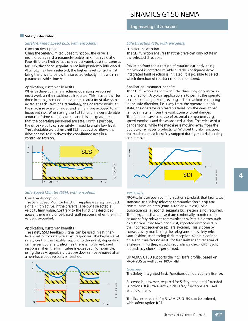
SINAMICS G150 NEMA
Engineering information
4
Siemens D11.7 (Part 1) – 2013
Safety integratedSafety integrated
G_D
211_
XX
_002
08
SLS
t
v
∆t
t
G_D
211_
XX
_002
09
v
1
0
Safely-Limited Speed (SLS, with encoders)
Function description Using the Safely-Limited Speed function, the drive is monitored against a parameterizable maximum velocity. Four different limit values can be activated. Just the same as for SOS, the speed setpoint is not independently influenced. After SLS has been selected, the higher-level control must bring the drive to below the selected velocity limit within a parameterizable time t. Application, customer benefitsWhen setting-up many machines operating personnel must work on the machine as it rotates. This must either be done in steps, because the dangerous area must always be exited at each start, or alternatively, the operator works at the machine while it moves and is therefore exposed to an increased risk. When using the SLS function, a considerable amount of time can be saved – and it is still guaranteed that the operating personnel are safe. For this purpose, the drive velocity can be safely limited to a safe low level. The selectable wait time until SLS is activated allows the drive control to run-down the coordinated axes in a controlled fashion.
Safe Speed Monitor (SSM, with encoders)
Function descriptionThe Safe Speed Monitor function supplies a safety feedback signal (high active) if the drive falls below a selectable velocity limit value. Contrary to the functions described above, there is no drive-based fault response when the limit value is exceeded.
Application, customer benefitsThe safety SSM feedback signal can be used in a higher- level control for safety-relevant responses. The higher-level safety control can flexibly respond to the signal, depending on the particular situation, as there is no drive-based response when the limit value is exceeded. For example, using the SSM signal, a protective door can be released after a non-hazardous velocity is reached.
4/17
Safe Direction (SDI, with encoders)
Function descriptionThe SDI function ensures that the drive can only rotate in the selected direction.
Deviation from the direction of rotation currently being monitored is detected reliably and the configured drive- integrated fault reaction is initiated. It is possible to select which direction of rotation is to be monitored.
Application, customer benefitsThe SDI function is used when the drive may only move in one direction. A typical application is to permit the operator access to a danger zone, as long as the machine is rotating in the safe direction, i.e. away from the operator. In this state, the operator can feed material into the work zone/ remove material from the work zone without danger.The function saves the use of external components e.g. speed monitors and the associated wiring. The release of a danger zone, while the machine is moving away from the operator, increases productivity. Without the SDI function, the machine must be safely stopped during material loading and removal.
PROFIsafePROFIsafe is an open communication standard, that facilitatesstandard and safety-relevant communication along one communication path (hard-wired or wireless). As a consequence, a second, separate bus system is not required. The telegrams that are sent are continually monitored to ensure safety-relevant communication. Possible errors such as telegrams that have been lost, repeated or received in the incorrect sequence etc. are avoided. This is done by consecutively numbering the telegrams in a safety-rele-vant fashion, monitoring their reception within a defined time and transferring an ID for transmitter and receiver of a telegram. Further, a cyclic redundancy check CRC (cyclic redundancy check) is performed.
SINAMICS G150 supports the PROFIsafe profile, based onPROFIBUS as well as on PROFINET.
LicensingThe Safety Integrated Basic Functions do not require a license.
A license is, however, required for Safety Integrated Extended Functions. It is irrelevant which safety functions are used and how many.
The license required for SINAMICS G150 can be ordered, with safety option K01.
G_P
M21
_XX
_001
16
v
t
SDI

SINAMICS G150 NEMA
Engineering information
4
Siemens D11.7 (Part 1) – 2013
4/14
4/18
An overview of the SINAMICS Safety Integrated functions plus their boundary conditions is provided in the following table.
Function Control Underlying function Reaction to limit overshoot
Encoderrequired
Licenserequired
Safety Basic Functions
STO • EP terminals on the power unit and digital input at the CU3xx/D4xx/CX32• PROFIsafe• Terminal module (24 V to 230 V),option K82 1)
SBC (if activated) – No No
SS1 • EP terminals on the power unit and digital input at the CU3xx/D4xx/CX32• PROFIsafe• Terminal module (24 V to 230 V), option K82 1)
STO, after a parameterizeddelay time has expired
STO No No
SBC • Via Safe Brake Adapter 2) – – No No
Safety Extended Functions
STO • Terminals on the TM54F 3)
• PROFIsafeSBC (if activated – Yes 4) Yes
SS1 • Terminals on the TM54F 3)
• PROFIsafeSTO is activated after the shutdown conditions have been fulfilled
STO Yes 4) Yes
SBC • Via Safe Brake Adapter – – Yes 4) Yes
SLS • Terminals on the TM54F 3)
• PROFIsafeUp to four maximum speeds for operation can be parameterized
STO, SS1 orSOS (can beparameterized)
Yes 4) Yes
SSM • Terminals on the TM54F 3)
• PROFIsafeSafe limit value monitoring in both directions of rotation, no independent drive response. A safety-relevant signal for further operation is generated.
– Yes 4) Yes
SDI • Terminals on the TM54F 3)
• PROFIsafe– STO, SS1 or
SOS (can beparameterized)
Yes 4) Yes
1) In addition for SINAMICS G150.2) Safe Brake Adapter has been released from firmware version 4.4.3) For SINAMICS G150 as option K87.4) The Safety Integrated Extended Functions require two incremental encoders (TTL, HTL or SSI) and therefore two SMC30 Sensor Module Cabinet-Mounted to evaluate the encoder signals (option K50 +K52).
Safety integrated

SINAMICS G150 NEMA
Engineering information
4
Siemens D11.7 (Part 1) – 2013
Emergency Stop compared to Safety Integrated functions
4/13
4/19
The principle of operation of Safety Integrated
Two independent shutdown pathsThere are two shutdown paths that are independent of one another.
All shutdown paths are low active. This therefore ensures that when a component fails or there is a wire break, then the system always goes into the safe state. When a fault is detected in the shutdown paths, the Safe Torque Off or Safe Stop 1 function (depending on the parameterization, also refer to the table on the Page 3/13) is activated and a restart is prevented.
Two-channel monitoring structureAll of the hardware and software functions important for Safety Integrated are implemented in two independent monitoring channels (e.g. shutdown paths, data management, data comparison). The safety-relevant data in the two monitoring channels is cyclically compared crosswise.
The monitoring functions in each monitoring channel are based on the principle that before a particular action, there must be a defined state, and after the action there must be a specific feedback. If this expectation is not fulfilled in a monitoring channel, then the drive is shutdown through two channels and the appropriate signal output.
Forced checking procedure using a test stop
In order to fulfill the requirements of ISO 13849-1 (previously EN 954-1) and IEC 61508 regarding early fault detection, the functions and the shutdown paths must be tested within a specific time period at least once to ensure that they are operating correctly. This must be realized either cyclically and manually or the test stop must be automatically initiated as part of the process.
The test stop cycle is monitored, and after a specific timehas been exceeded, an alarm is output.
A test stop does not require a power on. The acknowledgment is realized when deselecting the test stop request. When the machine is operational, it can be assumed that there is no risk for personnel as a result of the appropriate safety equipment (e.g. protective doors). As a consequence, the user is only made aware of the forced checking procedure that is required using an alarm, and is requested to perform the forced checking procedure at the next possible opportunity.Examples for performing the forced checking procedure:• When the drives are stationary after switching-on the system• Before opening the protective door• In a specified rhythm (e.g. every 8 hours)• In the automatic mode, time and event-triggered
What is the difference between options K82 STO/SS1 and N57 Emergency OFF category 0 respectively N59/N60 Emergency STOP category 1?
STO and Emergency OFF cat. 0 both result in a coast to stop, and SS1 and Emergency STOP cat. 1 both result in a fast ramp down with subsequent removal of power. All these designs incorporate safety relays.
Differences between these options are the standards and specifications that are being met. Safety Integrated functions
include strict requirements related to design, wiring, testing and start-up, and associated certification by qualified personnel at various stages. There are requirements for redundancy in certain circuits and components. These requirements apply to components and circuitry both inside the drive enclosure as well as outside in the plant.
The requirements met with Emergency OFF/Emergency STOP are not as extensive.
Safety integrated

SINAMICS G150 NEMA
Engineering information
4
Siemens D11.7 (Part 1) – 20134/20
Fail-safe inputs and outputs
TM54F Terminal Module
The TM54F Terminal Module (option K87) is a dual-processor I/O interface with 4 fail-safe digital outputs and 10 fail-safe digital inputs for using Safety Integrated functions of the SINAMICS G150 drive via external actuators and sensors.
All of the available safety functions integrated in the drive can be controlled via the fail-safe digital inputs of the TM54F Terminal Module.
The fail-safe digital outputs and inputs have two channels with an internal crosswise data comparison via the two processors. A fail-safe digital output consists of one P-switching and one M-switching output as well as one dig-ital input to read back the switching state. A fail-safe digital input consists of two digital inputs.
Safety sensors can be connected over two switchable 24 V sensor supplies and evaluated via the fail-safe digital inputs. The switchable 24 V sensor supply ensures that the fail-safe digital inputs can be dynamized to detect dormant errors (this dynamization is used to check the shutdown paths). A non-switchable 24 V sensor supply is additionally provided by the TM54F Terminal Module for connecting safety sensors that cannot be dynamized.
The TM54F Terminal Module is connected directly to a Control Unit via DRIVE-CLiQ. Each Control Unit can only be assigned to one TM54F Terminal Module.
Additional DRIVE-CLiQ nodes such as Sensor Modules and Terminal Modules (however no additional TM54F Terminal Module) can be operated on the TM54F Terminal Module.
The following are located on the TM54F Terminal Module:• 4 fail-safe digital outputs• 10 fail-safe digital inputs• 4 LEDs, single color for indicating the status of the read back channel of the fail-safe digital outputs• 4 LEDs, dual-color for indicating the status of the fail-safe digital outputs• 20 LEDs, dual-color for indicating the status of the fail-safe digital inputs• 3 LEDs, single color for indicating the status of the 24 V sensor supplies• 2 connections for 24 V sensor supply, switchable• 1 connection for 24 V sensor supply, non-switchable
The signal cable shield can be connected to the TM54F Terminal Module via a shield connection terminal, e.g. Phoenix Contact type SK8 or Weidmüller type KLBÜ CO 1. The shield connection terminal must not be used for strain relief.
The status of the TM54F Terminal Module is indicated via a multicolor LED.
Pins for connector coding are included in the TM54F Terminal Module scope of delivery.

SINAMICS G150 NEMA
Engineering information
4
Siemens D11.7 (Part 1) – 2013 4/21
Technical data
TM54F Terminal Module
Current demand(X524 at 24 V DC) without DRIVE-CLiQ supply
0.2 A
Max. current demand ext. 24 Vor supplying the digital outputs and 24 V sensor supply (X514 at 24 V DC)
4 A
I/O devices
• Number of fail-safe digital inputs 10
• Number of fail-safe digital outputs 4
• 24 V sensor supply 3, of which 2 can be internally shut down to dynamize fail-safe digital inputs, current carrying capacity of input is 0.5 A
• Connection system Plug-in screw-type terminals
• Wire size, max. #14 AWG (1.5 mm 2)
Digital inputsAccording to IEC 61131-2 Type 1,with electrical isolation
• Voltage -3 ... +30 V
• Low level (an open digital input is interpreted as “low”)
-3 ... +5 V
• High level 15 ... 30 V
• Current consumption at 24V DC, typ. >2 mA
• Delay time of digital inputs, approx 1)
- L H, typ. 30 s
- H L, typ. 60 s
• Safe state Low level (for inputs that can be inverted: without inversion)
Digital outputsContinuously short-circuit proof
• Voltage 24 V DC
• Load current per fail-safe digital output max. 2)
0.5 A
• Delay times (resistive load) 1)
- L H, typ. 300 s
- H L, typ. 350 s
• Safe state Output switched off
TM54F Terminal Module
Scanning cycle tSIfor fail-safe digital inputs or fail-safe digital outputs
4 ... 25 ms (adjustable)
Conformity CE
Approvals, according to cULus
Safety Integrated Safety Integrity Level 2(SIL2) acc. to IEC 61508,Performance Level d (PLd)acc. to ISO 13849-1 andControl Category 3 acc. to ISO 13849-1 (previously EN 954-1)
1) The specified delay times refer to the hardware. The actual reaction time depends on the time slot in which the digital input/output is processed.2) The total current of all fail-safe digital outputs must not exceed 5.33 A.
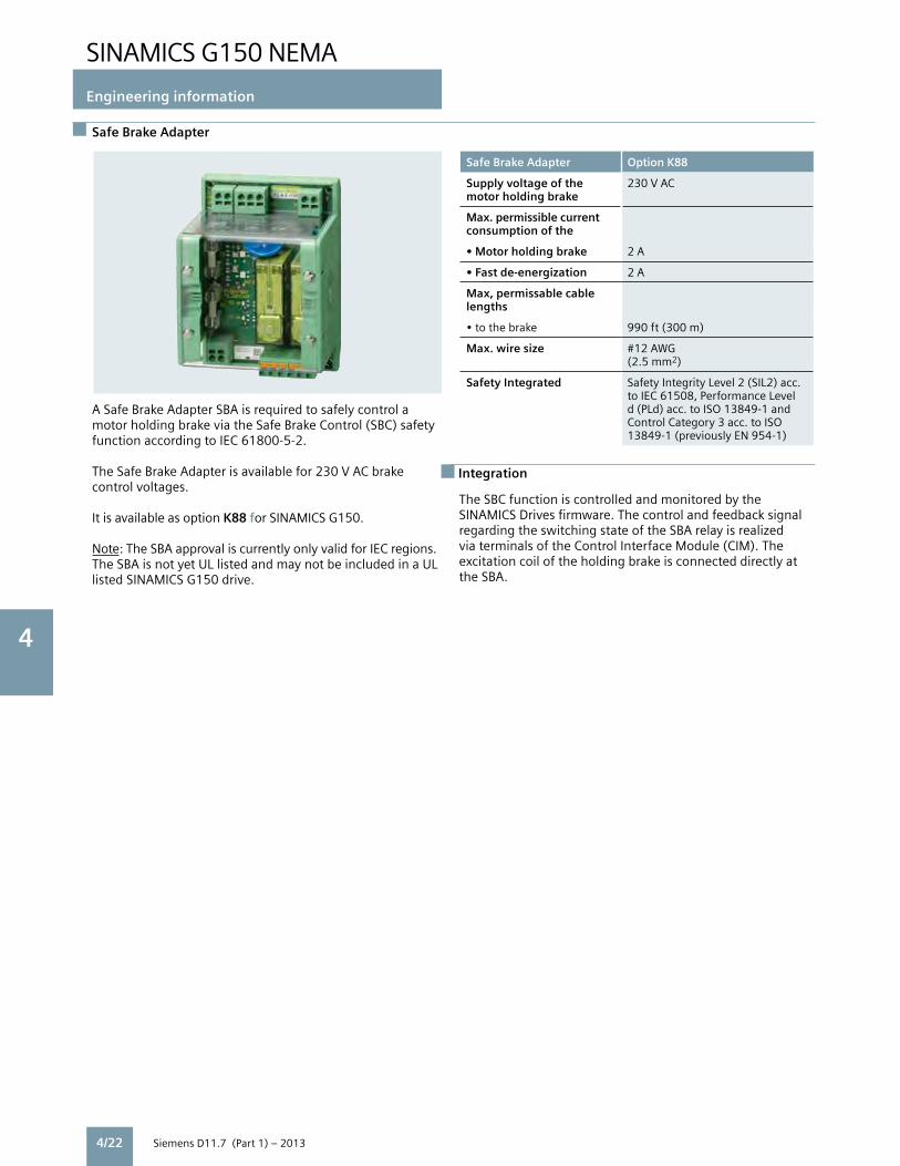
SINAMICS G150 NEMA
Engineering information
4
Siemens D11.7 (Part 1) – 20134/22
Safe Brake Adapter
Safe Brake Adapter Option K88
Supply voltage of the motor holding brake
230 V AC
Max. permissible currentconsumption of the
• Motor holding brake 2 A
• Fast de-energization 2 A
Max, permissable cable lengths
• to the brake 990 ft (300 m)
Max. wire size #12 AWG(2.5 mm2)
Safety Integrated Safety Integrity Level 2 (SIL2) acc. to IEC 61508, Performance Level d (PLd) acc. to ISO 13849-1 and Control Category 3 acc. to ISO 13849-1 (previously EN 954-1)
Integration
A Safe Brake Adapter SBA is required to safely control a motor holding brake via the Safe Brake Control (SBC) safety function according to IEC 61800-5-2.
The Safe Brake Adapter is available for 230 V AC brake control voltages.
It is available as option K88 for SINAMICS G150.
Note: The SBA approval is currently only valid for IEC regions. The SBA is not yet UL listed and may not be included in a UL listed SINAMICS G150 drive.
The SBC function is controlled and monitored by the SINAMICS Drives firmware. The control and feedback signal regarding the switching state of the SBA relay is realized via terminals of the Control Interface Module (CIM). The excitation coil of the holding brake is connected directly at the SBA.

SINAMICS G150 NEMA
Engineering information
4
Siemens D11.7 (Part 1) – 2013 4/23
Braking units
Braking units Braking units are used when the drive needs to absorb regenerative energy occasionally and briefly, for example when stopping it quickly (emergency stop). The braking units comprise a braking module and a braking resistor, which is installed externally.
Two sizes of braking units are available for the SINAMICS G150 type A enclosed drive with braking powers of 100 kW (for 150 HP & 200 HP, 460V) and 200 kW (for larger 460 V and 575V units). For higher braking powers, braking units may be connected in parallel for larger drives (on request, not for all ratings).
A thermal contact, which can be integrated into the drive’s alarm and shutdown sequence, is installed in the braking resistor for monitoring.
Determining the required braking units and braking resistors• For periodic duty cycles with a load duration of ≤ 90 s, the mean braking power value within this duty cycle must be determined. The relevant period should be used as the time base.• For periodic duty cycles with a load duration of ≥ 90 s or for sporadic braking operations, a 90 s time segment in which the greatest mean value occurs should be selected. A 90 s period should be set as the time base.
When determining the required braking unit rating (braking module and braking resistor), consider both the mean braking power value and the required peak braking power.
Basic Data
Supply voltage 380 V to 380 V to 500 V to 480 V 480 V 600 V Enclosed drive SINAMICS 150 HP to 250 HP to 150 HP to G150 type A 200 HP 800 HP 800 HP
Braking module 25 kW 50 kW 50 kW Continuous power PDB
Braking module 50 kW 100 kW 100 kW Power P40
Braking module 100 kW 200 kW 200 kW Rated power P20
Braking module 125 kW 250 kW 250 kW Peak power P15
Braking resistor RB 4.4 Ω 2.2 Ω 3.4 Ω ±7.5% ±7.5% ±7.5%
Max. current 189 A 378 A 306 A
Option code L61 L62 L62
Load diagram
Calculating the P20 power
To reduce the voltage stress on the motor and drive, the response threshold at which the braking unit is activated and the DC bus voltage generated can be reduced. For example, the DC bus voltage for the drives in the voltage range from 380 V to 480 V can be reduced from 774 V to 673 V. This also reduces the possible peak power. A factor of 1.06, rather than a factor of 0.8 should be used.
The ON/OFF states of the braking module are controlled by a 2-point controller. The respective response thresholds are shown in the following table:
Drive voltage range Braking unit response threshold
380 V to 480 V 774 V (673 V) 500 V to 600 V 967 V (841 V)
15P
20 P
40 P
DB P
DB P
15 P
20 P 40 P
t
=
= 5 x = Power which is permissible every 90 s for 15 s
= 4 x = Power which is permissible every 90 s for 20 s
= 2 x = Power which is permissible every 90 s for 40 s
1.00
10 20 30 40 50 60 70 80 90 100
0.75
0.50
0.25
s
1.50
1.25
DB P / P
DB P
15
DB P DB P
Rated power
G_D
211_
EN
_000
13a

SINAMICS G150 NEMA
Engineering information
4
Siemens D11.7 (Part 1) – 2013 4/15
Braking units, maintenance accessory
ExampleThe design of the braking unit is to be calculated for a 200HP (132 kW) drive.
The mean braking power is calculated as follows:
The Mean braking power = 90 kW x 17 s / 90 s = 17.0 kW
P20 = 4.5 x 17.0 kW = 76.5 kW
Peak power = 0.8 x 90 kW = 72.0 kW
Result:The mean braking power is the determining factor in the configuration of the braking module and braking resistor, i.e. a braking unit ≥ 76.5 kW should be provided.
The 100 kW braking unit is suitable.
When the response threshold is reduced, the required braking power P20 is calculated as follows:
Mean braking power = 90 kW x 17 s / 90 s = 17.0 kW
P20 = 4.5 x 17.0 kW = 76.5 kW
Peak power = 1.06 x 90 kW = 95.4 kW
Result:The peak power to be generated is the determining factor in the configuration of the braking module and braking resistor, i.e. a braking unit ≥ 95.4 kW should be provided.
The 100 kW braking unit is suitable.
4/24
Frame for exchanging power blocks
Power modules of SINAMICS G150 (and other SINAMICS and the MICROMASTER 4 chassis) contain one or more power blocks, depending on the frame size. The largest power blocks weigh of the order of 220 lb (100 kg) each.
To replace or repair power blocks on these drives, it is recommended that the auxiliary support frame described here is used. The frame has been designed for use with all existing sizes of power blocks.
The frame is vertically adjustable to cater for different mounting heights in enclosures. The frame is designed to be attached to the screw connections for the fan modules. These need to be unscrewed first. A range of mounting holes and adapters is provided to enable the frame to be mounted to any of the power block construction types.
Description Order no.
Frame for exchanging power blocks 6SL3766-1FA00-0AA0

SINAMICS G150 NEMA
Engineering information
4
Siemens D11.7 (Part 1) – 2013
STARTER commissioning tool
The user-friendly STARTER commissioning tool can be used for• Commissioning• Optimization• Diagnostics
This software can be operated either as a standalone PC application, or integrated in SIMATIC STEP 7 with TIA compatibility via Drive ES Basic. The basic functions and handling are the same in both cases.
Configuring can be realized both offline as well as online. If several drives are connected to the selected communication bus, then an online connection can be established to several drives simultaneously.
The project wizards can be used to create the drives within the structure of the project tree.
Beginners are supported by solution-based dialog guidance,whereby a standard graphics-based display maximizes claritywhen setting the drive parameters.
First commissioning is guided by a wizard which makes all the basic settings in the drive. Therefore, getting a motor up and running is merely a question of setting a few of the drive parameters as part of the drive configuration process.
The travel commands can be simply entered via the controlpanel from the PC.
The individual settings can be made using the graphicparameterizing screen forms, which precisely visualize the drive mode of operation. For experts, the expert list can be used to specifically andquickly access individual parameters at any time. An individual compilation of frequently used parameters can be saved in dedicated user lists and watch tables.
In addition, the following functions are available for optimization purposes:• Self-optimization of the controller settings (depending on the drive unit)• Trace to precisely record the signals• Numerous measuring functions such as step functions and frequency response analysis
Diagnostics functions provide information about:• Control/status words• Parameter status• Conditions of use• Communication states Performance features• User-friendly: Only a small number of settings need to be made for successful first commissioning: The motor starts to rotate• Solution-oriented dialog-based user guidance simplifies commissioning• Self-optimization functions reduce manual optimization work System requirements V4.2 and higher• PG or PC Pentium III min. 1 GHz (recommended > 1 GHz)• 1 GB RAM (recommended 2 GB RAM)• Screen resolution 1024 ×768 pixels, 16 bit color depth• Free hard disk memory min. 3 GB• Software - Microsoft Internet Explorer V6.0 or higher - 32 bit operating systems: Microsoft Windows Server 2003 SP2 Microsoft Windows Server 2008 Microsoft Windows XP Professional SP3 Microsoft Windows 7 Professional incl. SP1 Microsoft Windows 7 Ultimate incl. SP1 Microsoft Windows 7 Enterprise incl. SP1 (Standard Installation) - 64 bit operating systems: Windows 7 Professional SP1 Microsoft Windows 7 Ultimate SP1 Microsoft Windows 7 Enterprise SP1 (Standard Installation) Microsoft Windows Server 2008 R2
The STARTER commissioning tool is also available for updatepurposes on the Internet at www.siemens.com/starter
Selection and ordering data
Order No.
STARTER commissioning toolFor SINAMICS and MICROMASTERon DVD-ROMGerman, English, French, Italian, Spanish
6SL3072-0AA00-0AG0
More information
4/25
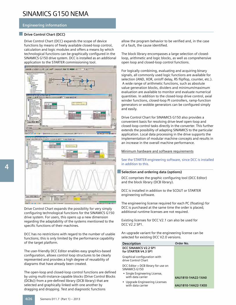
SINAMICS G150 NEMA
Engineering information
4
Siemens D11.7 (Part 1) – 2013
Drive Control Chart (DCC)
Drive Control Chart (DCC) expands the scope of device functions by means of freely available closed-loop control, calculation and logic modules and offers a means by which technological functions can be graphically configured in theSINAMICS G150 drive system. DCC is installed as an additionalapplication to the STARTER commissioning tool.
Drive Control Chart expands the possibility for very simply configuring technological functions for the SINAMICS G150 drive system. For users, this opens up a new dimension regarding the adaptability of the systems mentioned to the specific functions of their machines. DCC has no restrictions with regard to the number of usablefunctions; this is only limited by the performance capability of the target platform.
The user-friendly DCC Editor enables easy graphics-based configuration, allows control loop structures to be clearly represented and provides a high degree of reusability of diagrams that have already been created.
The open-loop and closed-loop control functions are defined by using multi-instance-capable blocks (Drive Control Blocks(DCBs)) from a pre-defined library (DCB library) that are selected and graphically linked with one another by dragging and dropping. Test and diagnostic functions
allow the program behavior to be verified and, in the case of a fault, the cause identified.
The block library encompasses a large selection of closed-loop, arithmetic and logic blocks, as well as comprehensive open loop and closed-loop control functions.
For logically combining, evaluating and acquiring binary signals, all commonly used logic functions are available for selection (AND, XOR, on/off delay, RS flipflop, counter, etc.). A wide range of arithmetic functions, such as absolute value generation blocks, dividers and minimum/maximum evaluation are available to monitor and evaluate numerical quantities. In addition to the closed-loop drive control, axial winder functions, closed-loop PI controllers, ramp-function generators or wobble generators can be configured simply and easily.
Drive Control Chart for SINAMICS G150 also provides a convenient basis for resolving drive-level open-loop and closed-loop control tasks directly in the converter. This further extends the possibility of adapting SINAMICS to the particular application. Local data processing in the drive supports the implementation of modular machine concepts and results in an increase in the overall machine performance.
Minimum hardware and software requirements
See the STARTER engineering software, since DCC is installedin addition to this.
DCC comprises the graphic configuring tool (DCC Editor) and the block library (DCB library). DCC is installed in addition to the SCOUT or STARTERengineering software.
The engineering license required for each PC (floating) for DCC is purchased at the same time the order is placed; additional runtime licenses are not required.
Existing licenses for DCC V2.1 can also be used for DCC V2.2 SP1.
An upgrade variant for the engineering license can be selected for existing DCC V2.0 versions.
Description Order No.
DCC SINAMICS V2.2 SP1for STARTER V4.3 SP1
Graphical configuration withdrive Control Chart DCC Editor + DCB library for use on SINAMICS G150 • Single Engineering License, with data carrier 6AU1810-1HA22-1XA0• Upgrade Engineering Licenses with data carrier 6AU1810-1HA22-1XE0
Selection and ordering data (options)
4/26

SINAMICS G150 NEMA
Engineering information
4
Siemens D11.7 (Part 1) – 20134/18
Complete life cycle service
For machine constructors, solution providers and plant operators: The service offering from Siemens industry, Automation and Drive Technologies includes comprehensive services for a wide range of different users in all sectors of the manufacturing and process industry.
To accompany our products and systems, we offer integrated and structured services that provide valuable support in every phase of the life cycle of your machine or plant – from planning and implementation through commissioning as far as maintenance and modernization.
Our Service & Support accompanies you worldwide in all matters concerning automation and drives from Siemens. We provide direct on-site support in more than 100 countries through all phases of the life cycle of your machines and plants.
You have an experienced team of specialists at your side to provide active support and bundled know-how. Regular training courses and intensive contact among our employees – even across continents – ensure reliable service in the most diverse areas.
Service & Support Contacts
Pre-sales Support, Order EntryPlease contact your local sales office.GA400 facility, Alpharetta, GA Phone: (770) 740-3000 e-mail: [email protected]
Technical SupportInside USA, toll free: 1-800-333-7421 Outside USA: +1(423)262-5710Online request: www.siemens.com/automation/support-request
Customer Service, Field Services, Spare Parts & RepairInside USA, toll free: 1-800-241-4453 Outside USA: +1(423)262-5711 e-mail: [email protected]
Training Start-up and maintenance training Siemens Industry offers the following course for SINAMICS G150:Course name: SINAMICS G Setup and MaintenanceCourse code: DVSNGM1ADuration: 4¹⁄₂ Days
The course includes:• Start-up of SINAMICS G150 using the AOP30 advanced operator panel.• Start-up of SINAMICS G150 from a PC with STARTER software. (STARTER is the common commissioning tool for all SINAMICS and MICROMASTER4 drives – from fractional HP to Megawatt, for low voltage and medium voltage drives).• Design of G150 drives• Exchanging hardware (controller unit, fan, power block etc.)
Please see the Siemens Industry SITRAIN Internet site for dates and costs of scheduled classes at:http://www.usa.siemens.com/training
Service and support
4/27

4/15
Siemens Industry, Inc. 3333 Old Milton Parkway Alpharetta, GA 30005 1-800-241-4453 [email protected]
Subject to change without prior notice.Order No: DRCA-D1171-0313 All rights reserved. Printed in USA. ©2013 Siemens Industry, Inc.
The information provided in this brochure contains merely general descriptions or characteristics of performance which in case of actual use do not always apply as described or which may change as a result of further development of the products. An obligation to provide the respectivecharacteristics shall only exist if expressly agreed in the terms of contract.
Siemens is a registered trademark of Siemens AG. Product names mentioned may be trademarks or registered trademarks of their respective companies. Specificationsare subject to change without notice.www.usa.siemens.com/drives