Embed Size (px)
DESCRIPTION
caterpillar tools
Citation preview

1-1
Diagnostic Tools
Table of Contents
Electrical Tools .............................................................................................................................................................. 1-3
Tools for Electronic Engines ...................................................................................................................................... 1-61
Engine Tools ................................................................................................................................................................. 1-93
Flow Tools ................................................................................................................................................................... 1-118
Measuring Tools ........................................................................................................................................................ 1-127
Paving Products ......................................................................................................................................................... 1-143
Power Train Tools ...................................................................................................................................................... 1-145
Speed Measuring Tools ............................................................................................................................................ 1-155
Temperature Measuring Tools ................................................................................................................................ 1-164
General Diagnostic Tools ......................................................................................................................................... 1-177
Diagnostic Tools

1-2
Dia
gnos
tic T
ools
Table of Contents

2578922
2828033
2737287
1-3
Diagnostic Tools
Electrical Tools
Electrical Tools
368-9910 Multi-Tool Group, Phase 3Model: AllWarranty: One Year
European Union compliant, CE marked
Step 1. Order the basic multi-tool group• Replaces 9 separate diagnostic tools in 1 multi-function unit (8T-1000 Position Indicator Group,
discontinued 8T-2700 Blowby/Air Flow Indicator Group, discontinued 8T-5200 Signal Generator/ Counter Group, 8T-5300 Engine Timing Indicator Group, 9U-7400, 9U-7401, 9U-7402 Multitach II, pressure, and burn rate computer)
• Reduces dealer cost by combining 9 tools into one; also provides greater convenience for technician• Usedasablowby/airflowindicator,signalgeneratorandcounter,electronicpositionindicator,enginetimingindicator,
multi-tachometer,thermometer,fuelmonitor,pressuregage,andflowcomputer• Provides technician with a hand-held unit with multiple diagnostic tools using a menu-driven display• Ergonomic design has large, dual control buttons for ease of use even with gloved hands• Large, color display is easily readable even in bright sunlight conditions• Diagnostic Interface Module (DIM) plugs into multi-tool to adapt existing diagnostic sensors and cables• Multi-tool uses many of the same cables and adapters used by existing tools (for this reason, purchase of new cables and
adapters may not be required)• Once a Diagnostic Interface Module (DIM) is used with a multi-tool, it should remain in use with only that multi-tool (inter-
changing DIM units and multi-tool units is not recommended without sending both units to the factory for calibration)• Foridentificationpurposes,correspondingserialnumbersareprintedonthebackofeachDIM• Modular design allows additional functions to be added as new software becomes available• All applications are activated and ready to use• An internal battery, universal AC power supply, and DC cable for vehicle battery power provides 3 options for supplying
power• 4 AC power cords are included for worldwide use368-9910 Multi-Tool Group, Phase 3 Includes:Carrying CaseNEHS1087 Tool Operating Manual
368-9910 Multi-Tool Group, Phase 3Part Number Description285-0896 5 Pin DIN Adapter (gender changer)285-0903 Cable Assembly with Ground Clip (used with 285-0900 Small
Blowby Tool Group)285-0904 Battery DC Power Cable Assembly (9-32 VDC)285-0905 Battery Pack (NiMH, 9.6 VDC)285-0906 Universal AC/DC Power Supply with 4 International Power
Cords (90 - 240 VAC)285-0907 Diagnostic Interface Module (DIM)285-0908 Multi-Tool368-9910 Multi-tool Group
Step 2. Order the sensors for the desired tool functionalitiesBlowby/Airflow Indicator• Allows technician to measure volume of blowby gases released through crankcase breather or air velocity through a com-
ponent, such as a radiator core• Blowby measurements provide helpful information when planning engine repairs• Airflowmeasurementsidentifypluggedorpartiallyrestrictedareas• Large blowby group checks blowby on 3500 Series and 3600 Series Engines, including ACERT™ models as well as on larger
300 Series Engines
(Continued)
2737287
1-4
Dia
gnos
tic T
ools
Electrical Tools
Step 2. Order the sensors for the desired tool functionalities (Continued)• Small blowby group works on engines smaller than 3500 Series Engines and smaller 300 Series Engines• Displaysblowbyandairflow,stripcharts,andmaximumandminimumvalueswithdifferences• Sample rate is adjustable• Select SAE or metric units• Print screen capability• Six language support: English, French, German, Italian, Portuguese, SpanishSignal Generator Group with Counter• Used to simulate signal from a magnetic speed pickup for troubleshooting electronic controls for transmissions, as a fre-
quency counter for pulsating AC or DC input, and for calibration of a number of electronic diagnostic tools• Allows technician to make frequency and amplitude adjustments simply by pushing a button• 285-0896 Five-Pin DIN Adapter, part of basic group, must be used to connect generator group cables to diagnostic interface
module• Print screen capability• Six language support: English, French, German, Italian, Portuguese, SpanishEngine Timing Indicator• Allows technician to measure an engines fuel injection timing• During timing test, multi-tool will chart engine RPMs vs degrees on built-in display• For diesel engines, multi-tool must be used with existing 8T-5301 Engine Timing Diesel Group and 285-0897 Engine Timing
Pickup Group• Checks engine timing on natural gas engines using 6V-9060 Engine Timing Gas Group and 285-0897 Engine Timing Pickup
Group• Also checks automatic timing advance unit on engines so equipped• Print screen capability• Six language support: English, French, German, Italian, Portuguese, SpanishElectronic Position Indicator (Upgraded)• Replaces mechanical dial indicators in applications where they cannot be used, such as rack measurements on an operat-
ing engine or any other rapidly changing dynamic reading• Simultaneously displays displacement, a strip chart, and maximum and minimum values with differences• Select SAE or metric units• Sample rate is adjustable• Print screen capability• Six language support: English, French, German, Italian, Portuguese, Spanish• 4 Channels• Record and PlaybackMultitach II• Simultaneously displays 4 channels, strip charts, minimum and maximum values at once• Analog gauge or digital display graphic• Set point indicator measurement• Print screen capability• Create channel labels• Six language support: English, French, German, Italian, Portuguese, SpanishDigital Thermometer• Simultaneously displays 4 channels, strip charts, minimum and maximum values at once• Analog gauge or digital display graphic• Two differential measurements• Bias out small differences between channels• Print screen capability• Create channel labels• Select SAE or metric units• Six language support: English, French, German, Italian, Portuguese, SpanishFuel Flow Monitor• Simultaneouslydisplays2engines(4flowmeters),burnrate,supplyflow,returnflow,total,grandtotal,time,average,win-
dowed average, burn rate, and strip chart• Sample rate is adjustable: slow, medium, normal• Print screen capability
(Continued)

2737287
1-5
Diagnostic Tools
Electrical Tools
Step 2. Order the sensors for the desired tool functionalities (Continued)• Create channel labels• Select SAE or metric units• Run time, elapsed time mode• Works with new 308-7271 Dual Turbine Flow Meter Group• Works with 179-0710 Burn Rate Group (6V-2198 Cable required)• Works with discontinued 154-8103, 154-8104, 168-7735, and 168-7745 Gear Meters (FT3098 Cable required)• Six language support: English, French, German, Italian, Portuguese, SpanishBurn Rate Computer• Replaces 179-0701 Burn Computer• Replaces 154-8106 Display• Print Screen• Create channel label• SAE or metric• Six languagesPressure• 3 pressure pickups with couplers 500; 6,000; 10,000 PSI• Analog/Digital Display• Two differential measurements• Print screen• Create channel labels• Select SAE or metric• Six languages
Sensor and Cable Groups Used with Multi-ToolPart Number Description
285-0897 Engine Timing Pickup Group5P-7362 Cable Assembly - Signal TDC6V-2197 Transducer - Magnetic TDC Pickup 114 mm
(4.5 in) long6V-2199 Adapter - Transducer, 1/8 in NPTF6V-3093 Adapter - Transducer, 1/4 in NPTF8T-5184 Transducer - Magnetic TDC Pickup 8.9 cm
(3.5 in) long8T-5185 Transducer - Magnetic 17.8 cm (7.0 in) long
6V-9060 Gas Engine Timing Adapter Group 1
1U-5524 Cable As. - Spark Timing Adapter8T-5258 Cable - Coil Adapter
8T-5301 Diesel Engine Timing Adapter Group 2
5P-7435 Adapter Group - Tee5P-7436 Adapter5P-7437 Adapter6V-2198 Extension Cable (X8)6V-3016 Washer285-0898 Electronic Position Indicator Group (also part of 8T-
1000 Electronic Position Indicator Group)6V-6042 Point Group - Contact8T-1002 Position Probe (X4)6V-2198 Extension Cable (X8)
Sensor and Cable Groups Used with Multi-ToolPart Number Description285-0899 Signal Generator Cable Group (also part of discon-
tinued 8T-5200 Signal Generator/Counter Group)8T-5112 Signal Input Cable8T-5197 Calibrator Cable and Adapters8T-5198 Transmission Adapter Cable6V-2198 Extension Cable (X8)
285-0900 Blowby Tool Group (Small Engine) (also part of discontinued 8T-2700 Blowby/Airflow Group) 3
285-0903 Cable Assembly with Ground Clip (used with 285-0900 Small Blowby Tool Group)
8T-2685 Pickup - Blowby (1,000 CFH)285-0901 Blowby Tool Group (Large Engine) 4
9M-0164 Clamps - Nose368-9911 Burn Rate Group
4C-9660 Carry Case179-0706 Foam Insert154-8099 Lid Foam Insert179-0705 Hose Group362-9907 Optional 12 to 24 VDC Invertor362-9913 Meter Cable
368-9914 Pressure Group6V-2198 Extension Cable (X8)376-4170 500 PSI (X1)376-4171 6,000 PSI (X2)376-4172 10,000 PSI (X1)
(Continued)

2737287
2737463
1-6
Dia
gnos
tic T
ools
Electrical Tools
Step 2. Order the sensors for the desired tool functionalities (Continued)
Sensor and Cable Groups Used with Multi-ToolPart Number Description
390-7879 Ball Stud Measurement Group4C-9656 Pelican Case™067-6809 Hex Bolt 3/8 x 5/8 (X4)8T-1002 Position Probe (X4)5P-4162 Contact Point (X4)6V-2198 Extension Cable (X8)390-7875 Magnetic Squaring Wedge390-7876 Magnetic Base (X4)390-7877 Probe Bracket (X4)390-7878 Foam5P-7590 Socket Screws 6-32 (X4)
308-7265 Multitach 2 Photo Group1U-6605 Retro-ReflectiveTape,12.5mm(0.5in)x1.5
m (5.0 ft) long6V-3137 Magnetic Mounting Base for 9U-51406V-3138 Extension Rod for 6V-31379U-5140 Pickup - LED Photo6V-2198 Extension Cable (X8)
308-7264 Multitach 2 Group9U-5140 Pickup - LED Photo1U-6605 Retro-ReflectiveTape,12.5mm(0.5in)x1.5
m (5.0 ft) long6V-3138 Extension Rod for 6V-31379U-7506 Magnetic Adapter Cable (required for TDC
Sensors)1P-7446 Rack Cable5P-1759 Tachometer Drive Group (additional parts
in accessory case)
Sensor and Cable Groups Used with Multi-ToolPart Number Description
308-7264 Multitach 2 Group (Continued)5P-7360 Tach Generator (20-tooth internal gear )8T-5111 Cable As. - Rack Adapter6V-2198 Extension Cable (X8)6V-3137 Magnetic Mounting Base for 9U-5140
308-7267 Digital Thermometer Group6V-2198 Extension Cable (X8)4C-4545 Adapter Group , 3/4 in O-ring4C-4547 Adapter Group , 1/2 in O-ring4C-6264 Probe - RTD 25.4 mm (1 in) long, 3. 2 mm
(0.125 in) diameter4C-6265 Probe - RTD 38.1 mm (1.5 in) long, 3.2 mm
(0.125 in) diameter4C-6266 Probe - RTD 63.5 mm (2.5 in) long, 3.2 mm
(0.125 in) diameter4C-6268 Exhaust Probe RTD5P-2720 Adapter Group - Probe, 1/8 in NPT5P-2725 Adapter Group - Probe, 1/4 in NPT5P-3591 Adapter Group - Probe, 9/16 in O-ring
308-7275 Hose Group (optional)285-0902 Accessory Case (for cables and sensors
[not included])308-7269 Accessory Case
308-7269 Accessory Case (not included)
1 Includes: Fiber Optic Receiver (not serviced), Fiber Optic Transmitter (not serviced), Fiber Optic Cable (not serviced)2 Includes: Injection Timing Transducer Assembly(not serviced)3 Includes: Bushing and Hose Group4 Includes: Blowby Probe (4,000 Cf/h maximum) and Blowby Hose (large engine)
308-7271 Fuel Flow Group
(Continued)

2737463
2828072
2828086
2737815
1-7
Diagnostic Tools
Electrical Tools
308-7271 Fuel Flow Group (Continued)
Part Number Description308-7271 Fuel Flow Group308-7273 Dual Turbine Mtr (2 meters)308-7274 Cable din to Mtr (2 cables)6V-3073 Case - Plastic
Step 3. Order the accessory case• 285-0902 Accessory Case holds and protects all cables
andsensorsthatarerequiredforallblowby/airflowindi-cator, signal generator group, engine timing indicator, and electronic position indicator only
• 308-7269 Accessory Case offers convenience of storing all cables, probes, and adapters for all seven applications at a lower cost
ReferencesNEHS1087, Tool Operating Manual, 348-5430 Multi-Tool Group NEHS0605, Tool Operating Manual, 9U-7400, 9U-7401, and 9U-7402 Multitach II SEHS8580, Special Instruction, Information and Use of 8T-5300 Engine Timing Group SEHS8579, Special Instruction, Use of 8T-5200 Signal Generator/Counter Group SEHS8623, Special Instruction, Using the 8T-1000 Position Indicator Group NEHS0776, 179-0710 Burn Rate GroupRepair InformationSPX Service Repair755 Eisenhower DriveOwatonna, MN 55060Attn: Repair DepartmentPhone: 800-344-4013Visit the SPX Repair Track web link to complete and submit the form for proper authorization: https://repairtrack.spx.comThe 308-7271 Fuel Flow Meter should have the calibration checked annually. ATS (Advanced Technology Service) can provide thisservice.Ifrecalibrationisrequired,thefuelflowmetersshouldbereturnedtoFlowDynamics,thesupplier.Recalibrationisrequirediftheflowmeterhasbeenphysicallydamaged.Improperstorageandcontaminationinthefuelcanleadtophysicaldamagetotheflowmeter.
Step 5. Memory Card• Multi-toolsoftwareupgradesareavailablebyorderingcompactflashmemory
cards preloaded with software• Theflashmemorycardsareavailablebyorderingtheappropriatepartnumber• The card is permanently inserted into the multi-tool CF slot• Phase I, 285-0910 Multi-Tool requires factory calibration before upgrade
(Continued)
2737815
2749187
1-8
Dia
gnos
tic T
ools
Electrical Tools
Step 5. Memory Card (Continued)
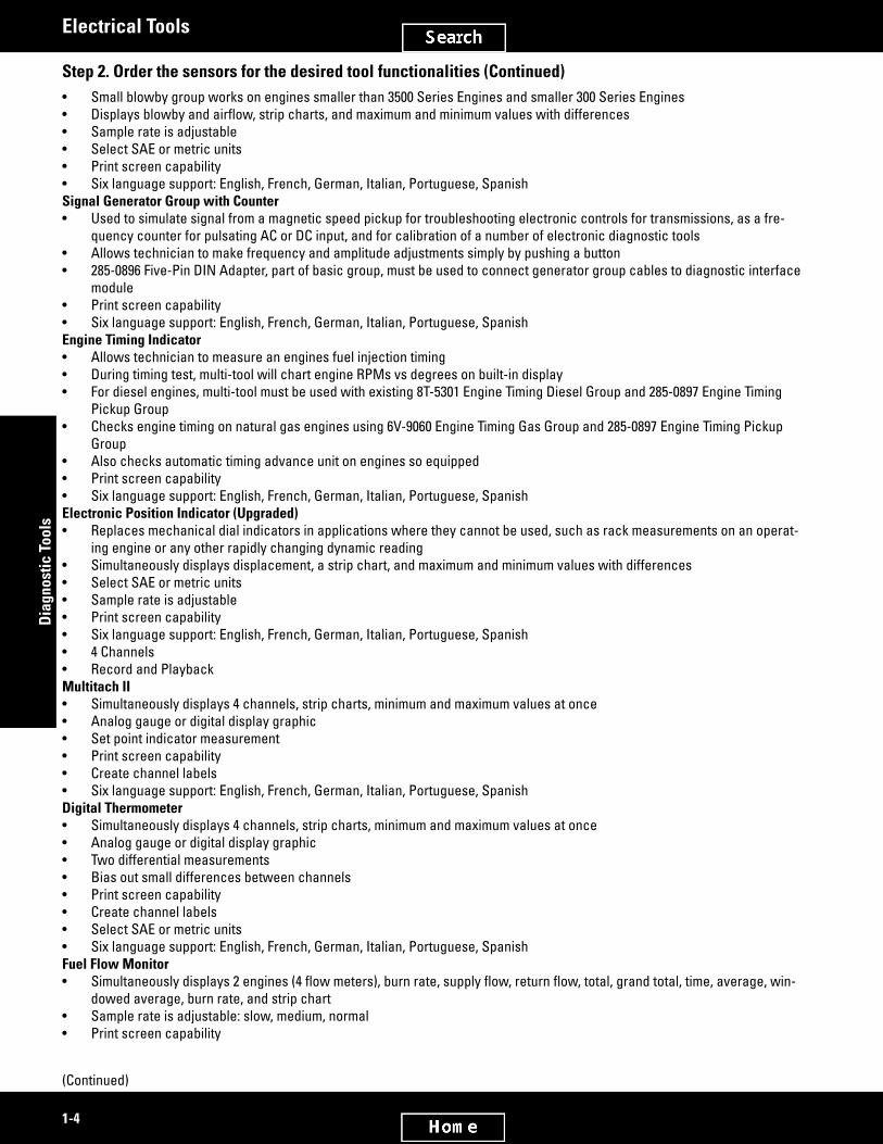
Multi-ToolSpecificationswithDIM(DiagnosticInterfaceModule)Global AC input voltage 90 to 240 VAC (50 to 60 Hz)Vehicle DC input voltage 9 to 36 VDC (must use 285-0904)¹Internal battery voltage 9.6 V (2300 mA hr)Battery operating time Approximately 2 hours (dependent on
sensor current draw)Output voltages (sensor power) 5 VDC @ 140 mA (total current 4 chan-
nels) 8 VDC @ 160 mA 12 VDC @ 500 mAOperating temperature 0° to 50° C (32° to 122° F)Storage temperature -20° to 70° C (-4° to 158° F)Analog voltage ± 100 V maximum inputSignal frequency 10 Hz - 100 kHz maximum input, 0.1 to 50
V, Sine WaveInput impedance > 500k ohmsDisplay 320 x 240 LCD, colorOutput frequency 1Hz to 100 kHzFrequency outputs 0 - 8 V, ± 4 V, ± 1.5 VFrequency output current 10 mA sink and source¹285-0904 DC Cable has a switching power supply to isolate and protect the multi-tool from harmful voltage transients Part No. Tool Function Description386-5908 CF Memory Card upgrade for phase 3 Multi-language (English, Spanish,
French, German, Italian, and Portuguese) forblowby/airflow,signalenerator/coun-ter, position indicator, upgrade engine timing indicator
Multitach 2, Digital Thermometer, Fuel Monitor (Phase 2), Burn rate computer, Pressure
Memory Card UsageInstructions for returning the multi-tool for re-calibration to the supplier:1. Wrap the Multi-Tool and DIM in a cushion-type packaging material, such as Bubble Wrap®.2. Include the following information with the Multi-tool and DIM:• Company Name• Contact Name• Return Address• Service Description (Calibrate for Digital Thermometer Application)• E-mail Address• Telephone Number• Dealer Name3. Properly package the Multi-Tool, DIM, and information and send to:SPX Service Repair755 Eisenhower DriveOwatonna, MN 55060 USAPhone: 800-344-4013Visit the SPX Repair Track web link to complete and submit the form for proper authorization: https://repairtrack.spx.com
(Continued)

2749187
2579116
1-9
Diagnostic Tools
Electrical Tools
Memory Card Usage (Continued)Upon receipt, Recalibration Service will contact you for credit card payment information. Caterpillar® will pay for the calibration. The dealer is responsible for shipping and handling fees. Allow about three weeks for calibration service and shipping. For status requests, contact Teleperformance at USA 1-800-344-4013. This program will end June 1, 2010.
225-8266 Clamp On AmmeterSMCS Code: 1400-038, 1400-081, 1450-038Model: AllWarranty: Manufacturer’s One Year
European Union compliant, CE marked• Used to measure AC or DC current• Compact size and low cost make this unit indispensible• Clamp-on probe replaces standard test leads (allows current measurements
without breaking circuit)• Measures current in cables up to 23 mm (0.9 in) diameter• User selectable 400 amp and 1200 amp scales for both AC and DC• Powered by two 1U-9533 AA Alkaline Batteries• Designed with a built-in display, push button zero control for DC operation, “dis-
play hold” to freeze display, “max/min recording” to display highest and lowest readings, auto power-off (unit turns off automatically after 30 minutes), and low battery indicator
• Shipped with batteries, carrying case, and users guideRepair InformationExtech Instruments9 Townsend WestNashua, NH 03061Phone: (781) 890-7440, ext: 220Fax: (781) 890-7864Email: [email protected] 190 g (6.7 oz)Overall size 183 x 61 x 36 mm (7.2 x 2.5 x 1.4 in)Resolution 1 A
Part Number Description225-8266 Clamp On Ammeter (400, 1200 A ranges)
Service/Repair Parts1U-9533 AA Alkaline Battery , non-rechargeable,
package qty 96 (5 required to power Indicator III)
6V-6014 Cable

2754050
2754071
1-10
Dia
gnos
tic T
ools
Electrical Tools
349-4205 Voltage DetectorSMCS Code: 1400-038, 1400-081Model: AllWarranty: Manufacturers Two Year
European Union compliant, CE marked• Used to quickly test for energized circuits (just touch tip to a terminal strip,
outlet, or supply cord)• SensessteadystateelectrostaticfieldproducedbyACVoltageeventhrough
wire insulation (does not require contact with bare conductor)• Tip will glow red if voltage is detected (high intensity red LED)• An optional beeping noise also indicates presence of voltage (feature can be
switched OFF)• Safety rating of CAT IV, 1000 V for added protection• Requires two AAA alkaline batteries (included)• Press “Battery Check Button” to determine if batteries are good (if tip glows,
batteries are good)• Each unit is supplied with a manufacturers operating instruction sheetOperating range 90 V AC to 1000 V ACOperating temperature -10 to 50° C (14 to 122° F)Operating altitude 3000 M (9850 ft)Voltage sensing range 90 to 1000 V AC; 45 to 405 Hz
Part Number Description349-4205 Voltage Detector
349-4199 AC/DC Probe (1000 Amp)SMCS Code: 1400-038, 1400-081Model: AllWarranty: Manufacturers One Year
European Union compliant, CE marked• Used to measure AC or DC current• Used with standard digital multimeter, recorders, digital or analog meters, data
loggers/DAS, oscilloscopes, or other test and measurement instruments• Converts high-current to a low level millivolt signal for input directly into a test
instrument• On/Off switch with red LED is illuminated when in On position• LowbatteryvoltageindicatedbyflashingLED• Zero adjustment knob (adjust output voltage to zero by depressing thumbwheel
and rotating)• Current range selection switch for 200A or 1000A• Includes carrying case, attached leads, and users manualMaximum conductor size 31 mm (1.2 in)Lead length 1.5 m (59 in)Meter input impedance 10 k Ohms minimum and 100 pF maximumCurrent ranges 200A and 1000A DC and AC peakOverall accuracy ±1% of reading ± 0.5AOperating temperature 0 to 50° C (32 to 122° F)Power 9 V battery, NEDA 1604, JIS 006P, IEC 6F22Battery life 50 hours (alkaline)Weight 295 g (10 oz)Size 55 x 220 x 30 mm (2.2 x 8.6 x 1.2 in)
(Continued)

2754071
2579185
1-11
Diagnostic Tools
Electrical Tools
349-4199 AC/DC Probe (1000 Amp) (Continued)SMCS Code: 1400-038, 1400-081Model: AllWarranty: Manufacturers One Year
Part Number Description349-4199 AC/DC Probe (1000 Amp)
271-8590 24-Volt Analyzer GroupModel: AllWarranty: Manufacturer’s
European Union compliant, CE marked• Used to perform battery, electrical system, and diode tests• Used with 225-8266 Amp Probe and 271-8585 Printer• Used on 12 and 24 volt electrical systems (digital circuitry
accurately controls testing — requires minimal interac-tion)
• Hand-held• Large, backlit display requires less scrolling, provides
more information• Long 4.6 m (15.0 ft) cables allow operator to perform tests
from cab of machine• Step-by-step instructions quickly and easily guide techni-
cian through tests• Testsfloodedleadacidandabsorbedglassmat(AGM)
batteries with 50 to 4000 Cold Cranking Amp (CCA), Crank-ing Amp (CA), Amp Hours (A-HR), Japanese Industrial Standard (JIS), or German-Deutsche Industry Norm (DIN) capacity ratings
• Testsbatterypackconfigurations,throughalgorithmdesign: - single battery, 6- or 12-volt - 2 batteries in series, 24-volt - 2, 3, or 4 batteries in parallel, 12-volt - 2 banks in parallel, each bank with batteries in series, 24-volt
• Internalresistanceloadsareappliedforallconfigurations• Amp clamp connections allow use of optional amp clamp
cables for current drain and starting/charging tests
• Features infrared communications compatibility for op-tional wireless printer withuserdefinedheaderandfooterforcustomprintouts
• PC interface port allows unit updates as new software is released — download software for new battery types, system updates, and features
• Ergonomically designed over-molded surround with soft-touch keys for easy operation while wearing gloves during cold weather
• Security cable connection tethers tool in order to prevent drops or for security purposes
• Includes 24-volt analyzer, test cables, battery terminal adapters, manual, and case with foam insert
(Continued)

2579185
1-12
Dia
gnos
tic T
ools
Electrical Tools
271-8590 24-Volt Analyzer Group (Continued)Model: AllWarranty: Manufacturer’s
Repair Information The unit is warrantied by the manufacturer for 3 years from the date of receipt. Cables are warrantied for 90 days from the date of receipt. If the unit needs servicing, contact the manufac-turer’s repair facility.SPX Service Repair755 Eisenhower DriveOwatonna, MN 55060Attn: Repair DepartmentPhone: 800-344-4013Visit the SPX Repair Track web link to complete and submit the form for proper authorization: https://repairtrack.spx.comReferenceNEHS0973, Tool Operating Manual, 271-8590 Analyzer Group (24 Volt)Item DescriptionBattery tests Flooded lead acid (FLA) ab-
sorbed glass mat (AGM)Cold cranking amp range 50 - 4000 CCA / 24 VBattery voltage Single, series, or parallel to
24 VElectrical system tests 12 and 24 V, starting/charging/
diode testScales CCA, CA, AHR, MCA, JIS, DINPC interface ForfieldsoftwareupdatesIR compatible For optional infrared wireless
printerAmp clamp ports For optional amp clamp con-
nectionsDisplay Backlit 4 x 20 character
display
Part Number Description271-8590 24-Volt Analyzer Group
Replacement Parts271-8587 Test cables, 4.6 m (15 ft)281-1947 Rechargeable Battery281-1950 Carrying Case with Foam Insert271-8589 Analyzer Only
Part Number DescriptionOptional Accessories
225-8266 Clamp On Ammeter (400, 1200 A ranges)
271-8585 Optional Printer Group281-1948 Printer Serial Cable184-7679 Paper - Roll

2579215
2579239
1-13
Diagnostic Tools
Electrical Tools
177-2330 Digital Battery AnalyzerSMCS Code: 1401-081, 0785Model: AllWarranty: One Year
• Replaces 127-8078 Battery Analyzer• Used to quickly and accurately test condition of 6 and 12 volt batteries (even
discharged to as low as 4 volt• Check for full state charge, condition of battery, and battery voltage in 20 sec-
onds• Test batteries in machine or vehicle without disconnecting battery cables• Battery does not have to be fully charged at time of testing• Saves time and money by allowing dealers to test condition of a battery while
customer is present (works great for warranty claims)• Eliminates need to charge and discharge a battery to test its condition• Compensates for cold temperatures when testing batteries in extreme condi-
tions• Power-down feature prolongs battery life in analyzer• Analyzer has reverse polarity and is protected to 17 volts maximumReferencesNEHS0764, Tool Operating Manual, Using the 177-2330 Battery AnalyzerBattery rating range:Cold cranking amps (CCA) 50 - 4000Cranking amps (CA) 65 - 5000Ampere hours (A h) 6 - 500DC voltmeter range 1.0 - 14 VVoltmeter accuracy ±0.1 VPower source 9 V battery or test batteryTest time 20 secondsAnalyzer cable length 815 mm (32 in)Overall size 210 x 140 x 38 mm (8.25 x 5.5 x 1.5 in)Weight 0.68 kg (1.5 lb)Operating temperature range 0° to 50° C (32° to 120° F)Storage temperature range -20° to 70° C (0° to 160° F)Over voltage protection Up to 18 V
Part Number Description177-2330 Digital Battery Analyzer
4C-4911 Battery Load TesterSMCS Code: 1401-081, 0785Model: All ModelsWarranty: One Year
• Used to test 6, 8 and 12 volt heavy equipment and automotive batteries• Has built-in LCD digital voltmeter and ammeter• Load adjustment knob for current drawn from battery to be adjusted up to maxi-
mum of 1000 amperes• Cooled by internal fan automatically activated when load applied to prevent
carbon pile overheating• Large, 15 mm (0.59 in) high display digits are easier to readReferenceSEHS9249, Special Instruction
(Continued)

2579239
2979460
1-14
Dia
gnos
tic T
ools
Electrical Tools
4C-4911 Battery Load Tester (Continued)SMCS Code: 1401-081, 0785Model: All ModelsWarranty: One Year
Load test 6, 8 and 12 V batteriesLoad current 0 - 1000 A (carbon pile)Duty cycle Continuous, limited only by cable and
clamp heatingOperating temperature 0° - 50° C (32° ± 122° F)Voltmeter accuracy 0.1% of full scale ± 1 digitAmmeter accuracy ±3% of reading ± 1 digitSize 33 x 33 x 30 cm (13 x 13 x 12 in)Weight 12.428 kg (27.375 lb)
Part Number Description4C-4911 Battery Load Tester
372-5253 Battery Tester with Expansion CapabilitiesModel Usage: CT660 TruckWarranty: Manufacturer’s
• Used to test batteries in multi-battery vehicles• Test up to 6 batteries in parallel without disconnecting• Test 6 and 12V batteries, group 31 and commercial batteries, AGM and Gel, test
12 and 24V starting and charging systems• Cable-drop test simultaneously calculates voltage drop across positive and
negative sides of any circuit and total circuit drop without running engine• Digital multi-meter capabilities with scope and infrared temperature readings• Displays voltage, measured CCA, battery, starting and charging system condi-
tion, SD memory card capable for record keeping, data transfer, and software upgrades.
• Recall last test on screen or print to optional printerSpecificationsDimensions 9.5 x 4 x 2.5 inWeight 0.43 kg
Part Number Description372-5253 Battery Tester with Expansion Capabili-
ties

2579258
2579278
2579305
1-15
Diagnostic Tools
Electrical Tools
8T-0500 Continuity Testing LightSMCS Code: 1000-017, 1000-025, 1250-025, 1250-036, 1355-081, 1400-038, 3071-017, 3100-017, 3156-010, 3156-012, 3200-038, 3224-025, 4208-010, 5050-038, 7400-036, 7451-038, 7401-045Model: All ModelsWarranty: One Year
• Used to test non-energized circuits; lamp comes on brightly when connected across low resistance circuit; no light appears if resistance of circuit exceeds 10 ohms
• Designedforruggedfielduse• Comes with light bulb and 2 “N” size batteries (1.5 volts) and instruction decalsReferenceNEHS0543, Special Instruction, Checking Diodes
Part Number Description8T-0500 Light - Continuity Testing
Service/Repair Parts4C-8363 Battery, Size N, 1.5 V6V-3061 Bulb
5P-7277 Voltage TesterSMCS Code: 1400-038, 1400-081, 1450-081, 1700-081, 1800-081, 3168-035, 5050-081, 7300-081, 7400-081, 7451-038Model: 215, 428, 621E, 627E, 768C, 769C, 793 All modelsWarranty: One Year
• Used to make quick checks for presence of voltage• Indispensable for checking out circuits, relays, bulbs, wires, and switches• Designed for voltage range from 12 to 36 volts• Bulb lights brightly when connected to 36 volts and gets progressively dimmer
with lower voltages• Encased in rugged, high-impact plastic housing which is grease and chemical
resistant• Standard 8D-1429 Bulb required for replacement
Part Number Description5P-7277 Voltage Tester
197-7875 Lock Removal Tool197-7876 Connector Removal ToolSMCS Code: 1800-0776Model: AllWarranty: Six Months
• Used to service Cat® fuse blocks using mini-fuses (GM style)• 197-7875 used to remove fuse block terminal locks• 197-7876 used to remove wire and terminal from RTA, if replacement is neces-
saryInstructions for use of 197-7875– FromrearsideofRTA,inserttoolfingersintoslotsonoutboardsideofwires.– With tool handle parallel to wires, press down on locking tabs of terminal locks.– Pulloutterminallocksbyhandorwithasmall,flatbladescrewdriver.Instructions for use of 197-7876– Remove fuse from top of RTA.– Locate wire terminal on outboard sides of RTA.– Placelongsquarefingersintosquareholesaboveandbelowslotforfuseblade.– Pressremovaltoolfingers
completely into connector to compress terminal locking tabs.– Remove wire and terminal.
(Continued)

2579305
2579333
1-16
Dia
gnos
tic T
ools
Electrical Tools
197-7875 Lock Removal Tool (Continued)197-7876 Connector Removal ToolSMCS Code: 1800-0776Model: AllWarranty: Six Months
Part Number Description197-7875 Lock Removal Tool197-7876 Connector Removal Tool
140-9944 Terminal KitSMCS Code: 1400-023, 0700Model: All Cat® EnginesWarranty: Six Months
• Replaces discontinued 1P-2305 Terminal Kit• Used to repair wiring harness terminal ends which have become damaged or
unserviceable• Hand crimping tool has built-in dies for crimping insulated and non-insulated
terminals, cutting edges for cutting wire, notches for stripping 10 to 22 gauge wire, shears for cutting up to 4.7 mm (0.18 in) diameter bolts, 2-thread chasers for screws with 24 and 32 threads-per-inch screws, and a scale for measuring screw length
• Splice connectors have hot-melt adhesive and shrink ends that when heated will provide an environmental seal around wire
Qty. Shipped Part No. Description
Replacement Qty.
1 140-9944 Terminal Kit 1Terminal and Wire Splice Service/Repair Parts
1 9S-9150 Terminal Crimp Tool 110 2L-8058 Terminal (8 Gauge 1/4 in Stud) 1010 2L-8066 Terminal (12 - 10 Gauge No. 10 Stud) 1010 2L-8067 Terminal (12 - 10 Gauge 1/4 in Stud) 1010 2L-8069 Terminal (12 - 10 Gauge 3/8 in Stud) 1010 2L-8071 Terminal (12 - 10 Gauge 1/2 in Stud) 1020 2L-8075 Terminal (16 - 14 Gauge No. 8 Stud) 2020 2L-8076 Terminal (16 - 14 Gauge No. 10 Stud) 2015 2L-8077 Terminal (16 - 14 Gauge 1/4 in Stud) 1515 2L-8079 Terminal (16 - 14 Gauge 3/8 in Stud) 1530 5P-4571 Terminal (16 - 14 Gauge) 2010 4S-1988 Terminal (Blade, Crimp Type) 5015 136-4876 Wire Splice (12 - 10 Gauge) 115 136-4877 Wire Splice (16 - 14 Gauge) 115 136-4878 Wire Splice (22 - 18 Gauge) 1

2579369
2579390
1-17
Diagnostic Tools
Electrical Tools
8T-5319 CE/VE Connector Tool GroupSMCS Code: 1400-023Model: All Models with CE/VE ConnectorsWarranty: Six Months
• Used to service all CE/VE Connectors• Contacts can be removed, installed or rearranged within connectorReferenceSEHS8038, Special Instruction
Item Tool Part No. Description Color Wire Gauge— 8T-5319 Connector Tool Group — —
Connectors1 4C-4074 Removal Tool, 16 - 18 Gauge Black 16, 182 4C-4073 Removal Tool, 12 - 14 Gauge Yellow 12, 143 4C-4072 Removal Tool, 8 - 10 Gauge Green 8, 104 4C-4071 Removal Tool, 4 - 6 Gauge Grey 4, 6
6V-4148 Electrical Connector Repair KitModel: Some models with electronic controlsWarranty: Six Months
• Used to repair electrical connectors made by Amp Special Industries that are used in electrical controls and harnesses
Part Number Description9G-5859 Includes: 301741 Terminal (8) 384841 Contact (18) 384843 Plug (12) 309491 Housing (16) 309492 Housing (16) 301782 Housing (10) 301531 Housing (4) 344953 Housing (4) 301739 Socket (8) 301740 Housing (10) 301781 Housing (10) 9G-6790 Includes: 399860 Contact (22) 368748 Connector 368747 Connector 389688 Connector (2)
(Continued)

2579390
2579415
1-18
Dia
gnos
tic T
ools
Electrical Tools
6V-4148 Electrical Connector Repair Kit (Continued)Model: Some models with electronic controlsWarranty: Six Months
Part Number Description6V-3001 Sure Seal Crimping Tool6V-4145 Extraction Tool6V-4146 Extraction Tool - 301530 Terminal (8)6V-4147 Extraction Tool - 399862 Housing (4)6V-4148 Electrical Connector Repair Kit7N-6545 Terminal (32)
Part Number Description7N-6546 Terminal (32)9G-5859 Pin (8)9G-6789 Connector (2), 387062 Connector (2)9G-6790 Socket (37)9G-6791 Pin (32)9G-6793 Terminal (9), 384842 Connector (6)
300-8648 Insulation Tester GroupSMCS Code: 4450-082, 0785Model: General and Generator SetsWarranty: Manufacturers One Year OEM
European Union compliant, CE marked• Replaces discontinued 243-3134 1KV Insulation Tester• Used to test insulation on generator sets, cables, motors,
insulators, and wiring installations• Test voltages of 50, 100, 250, 500, and 1000 volts• Automatic calculation of Dielectric Absorption Ratio
(DAR) and Polarization Index (PI)• Repetitive or hard-to-reach testing is made easier with
300-9489 Remote Test Probe• Make repetitive tests simple and easy with Compare
(Pass/Fail) function• Live circuit detection prevents insulation test if voltage of
30 volts or greater is detected• Auto-discharge of capacitive voltage for added user
protection• Auto power off extends battery life• CAT IV 600 volt overvoltage• Read measurements easily with large, backlit display• 4 AA alkaline batteries provide at least 1000 insulation
tests
Part Number Description300-8648 Insulation Tester Group
Service/Repair Parts300-8649 Test Leads300-8650 Test Probes300-9487 Alligator Clips
Part Number DescriptionService/Repair Parts (Continued)
300-9488 Case300-9489 Remote Test Probe

2809257
1-19
Diagnostic Tools
Electrical Tools
AC/DC Voltage Measurement
AC/DC Voltage MeasurementAccuracy 50 Hz to 400 Hz ± (% of reading + digits): ± (2% of reading + 3
digits)Range 0.1 V to 600.0 VResolution 0.1 VInput impedance 3 MΩ (nominal), < 100 pFCommon mode rejection ratio (1 kΩ unbalanced) > 60 dB at DC, 50 or 60 HzOverload protection 600 V RMS or DC EarthBondResistanceMeasurementSpecificationsRange/Resolution 20.00 Ω / 0.01 Ω 200.00 Ω / 0.1 Ω 2000 Ω / 1.0 Ω 20.00 kΩ / 0.01 kΩAccuracy ± (1.5% of reading + 3 digits)Overload protection 2 V RMS or DCOpen circuit test voltage > 4.0 V, < 8 VShort circuit current > 200.0 mA InsulationSpecificationsMeasurement range 0.01 MΩ to 10 GΩTest voltages 50 V, 100 V, 250 V, 500 V, and 1000 VTest voltage accuracy + 20%, - 0 %Short-circuit current 1 mA nominalAuto discharge Discharge time < 0.5 second for C = 1 μF or lessLive circuit indicator Inhibit test if terminal voltage > 30 V prior to initialization of testMaximum capacitive load Operable with up to 1 μF loadMeasure accuracy 50 V: ± (3% + 5) 100 V: ± (3% +5) 250 V: ± (1.5% + 5) 500 V: ± (1.5% + 5) 1000 V: ± (1.5% + 5) to 2000 MΩ, ± (10% + 3) above 2000 MΩ

2749851
1-20
Dia
gnos
tic T
ools
Electrical Tools
Environmental Specifications
EnvironmentalSpecificationsMaximum voltage applied to any terminal 600 VAC RMS or DCStorage temperature -40° to 60° C (-40° to 140° F)Operating temperature -20° to 55° C (-4° to 131° F)Temperaturecoefficient 0.05x(specifiedaccuracy)per°Cfortemperatures<18or>28
°C (< 64 or > 82 °F)Relative humidity 0% to 95% at 10° to 30° C (50° to 86° F) 0% to 75% at 30° to 40° C (86° to 104° F) 0% to 40% at 40° to 55° C (104° to 131° F)Vibration Random, 2 g, 5 - 500 Hz per MIL-PRF-28800F, Class 2 instrumentShock 1 meter drop per IEC 61010-1 2nd Edition (1 meter drop test, 6
sides,oakfloor)Electromagnetic accuracy (EN 61326-1:1997) compatibility InanRFfieldof3V/M,accuracy=specified Compliance to StandardsComplies with ANSI/ISA 82.02.01 (61010-1) 2004, CAN/CSA-C22.2 NO. 61010-1-
04, and IEC/EN 61010-1 2nd Edition for measurement category IV 600 V (CAT IV)
Certifications CSA per standard CSA/CAN C22.2 No. 61010.1-04; TUV per standard IEC/EN 61010-1 2nd Edition
PowerSpecificationsBatteries 4 AA batteries (NEDA 15A or IEC LR6) Battery LifeInsulation test use Tester can perform at least 1000 insulation tests with fresh
alkaline batteries at room temperature. These are standard tests of 1000 V into 1 MΩ with a duty cycle
of 5 seconds on and 25 seconds off.Resistance measurements Tester can perform at least 2500 earth bond resistance mea-
surements with fresh alkaline batteries at room temperature. These are standard tests of 1Ω with a duty cycle of 5 seconds
on and 25 seconds off. GeneralSpecificationsSize (H x W x L) 5.0 x 10.0 x 20.3 cm (1.97 x 3.94 x 8.0 in)Weight 550 g (1.2 lb)IP Rating IP40Operating altitude 2000 m CAT IV 600 V, 3000 m CAT III 600 VNon-operating (storage altitude) 12,000 mOver-range capability 110% of range

2828669
3038358
1-21
Diagnostic Tools
Electrical Tools
349-4206 5KV Insulation Tester GroupSMCS Code: 4450-082, 0785Model Usage: General and Generator SetsWarranty: Manufacturer’s Three Years
• Used to test insulation on generator sets, cables, motors, insulators, and wiring installations
• Test voltages of 50, 100, 250, 500, 1000, and 5000 volts• Automatic calculation of Dielectric Absorption (DAR) and Polarization Index (PI)• Selectable test Voltages in 50 V steps from 250 to 1000 V and 100 V steps above.• Measurements can be stored in up to 99 memory locations with each location
assignedauniqueuser-definedlabelforeasyrecall• Resistance measurements up to 1TΩ (ohm)• Long battery life gives the user over 750 tests between charges• CE, CSA, and TUV CompliantSpecificationsDimensions 170 x 242 x 330 mm (6.7 x 9.5 x 13 in)Weight 3.6 kg (7.94 lbs)Safety CAT III 1000 V, CAT IV 600VDisplay 75 x 105 mm (3.0 x 4.1 in)Power, Battery 12 V lead-acid rechargeabe Yuasa NP
2.8 - 12Charger Input (AC) 85 V to 250 V 50/60 HZ 20 VATemperature (operating) -20° C to 50° C (-4° F to 122° F)Temperature (storage) -20° C to 65° C (-4° F to 149° F)Electromagnetic Compatibility EN 61326Humidity 80% to 31° C decreasing linearly to 50%
at 50° C
Part Number Description349-4206 5KV Insulation Tester Group
417-5122 Fluke Ti32 Thermal CameraModel Usage: AllWarranty: Manufacturer’s
European Union Compliant, CE marked• Used to ensure proper connections are made in high voltage and current wiring
installations• Used to identify potentially insulation problems• Use to view slowly changing temperatures on electrical switchgear, wiring and
generator sets• Compact and portable• Includes IR-Fusion and SmartView analyzing and reporting software• 320 x 240 resolution infrared thermal imager• Optional wide-angle and telephoto lenses available
(Continued)

3038358
1-22
Dia
gnos
tic T
ools
Electrical Tools
417-5122 Fluke Ti32 Thermal Camera (Continued)Model Usage: AllWarranty: Manufacturer’s
TemperatureTemperature measurement range (not calibrated below -10° C)
-20 °C to + 600 °C (-4 °F to + 1112 °F)
Temperature measurement accuracy ± 2 °C or 2% (at 25 °C nominal, whichever is greater)
On-screen emissivity correction YesOn-screenreflectedbackgroundtem-perature compensation
Yes
On-screen transmission correction Yes Imaging PerformanceImage capture frequency 9 Hz refresh rateDetector type Focal Plane Array, uncooled microbolom-
eter, 320 x 240 pixelsThermal sensitivity (NETD) ≤ 0.05 °C at 30 °C target temp. (50 mK)Infrared spectral band 7.5 μm to 14 μm (long wave)Visual (visible light) camera Industrial performance 2.0 megapixelMinimum focus distance 46 cm (approx. 18 in)Standard infrared lens type Field of view: 23° x 17° Spatial resolution (IFOV): 1.25 mRad Minimum focus distance: 15 cm (approx.
6 in)Focus mechanism Manual, one-handed Smart Focus capa-
bility
Part Number Description417-5122 Fluke Ti32 Thermal Camera

3038491
1-23
Diagnostic Tools
Electrical Tools
Ti32 Thermal Camera Image Specifications
Image PresentationPalettes Standard: Ironbow, Blue-Red, High Contrast, Amber, Amber
Inverted, Hot Metal, Grayscale, Grayscale Inverted Ultra Contrast™: Ironbow Ultra, Blue-Red Ultra, High Contrast
Ultra, Amber Ultra, Amber Inverted Ultra, Hot Metal Ultra, Gray-scale Ultra, Grayscale Inverted Ultra
Level and span Smooth auto-scaling and manual scaling of level and spanFast auto toggle between manual and auto modes YesFast auto-rescale in manual mode Yes IR-Fusion® InformationPicture-In-Picture (PIP) Three levels of on-screen IR blending displayed in center of
LCDFull screen infrared Three levels of on-screen IR blending displayed in center of
LCDColor alarms (temperature alarms) High-temperature color alarm (user-selectable)Voice annotation 60 seconds maximum recording time per image; reviewable
playback on imager Image capture and data storageImage capture, review, save mechanism The Ti32 allows user to adjust palette, blending, level, span, IR-
Fusion®mode,emissivity,andreflectedbackgroundtempera-ture compensation, and transmission correction on a captured image before it is stored. One-handed image capture, review, and save capability.
Storage medium SD memory card (2 GB memory card will store at least 1200 fully radiometric (.is2) IR and linked visual images each with 60 seconds voice annotations, or 3000 basic bitmap (.bmp) images, or 3000 jpeg (.jpeg) images; transferrable to PC via included multi-format USB card reader
File formats Non-radiometric (.bmp) or (.jpeg) or fully-radiometric (.is2) No analysis software required for non-radiometric (.bmp and
.jpg)filesExportfileformatsw/SmartView® software BMP, DIB, GIF, JPE, JFIF, JPEG, JPG, PNG, TIF, and TIFFMemory review Thumbnail view navigation and review selection

3038507
1-24
Dia
gnos
tic T
ools
Electrical Tools
Ti32 Thermal Camera General Specifications
GeneralspecificationsOperating temperature -10 °C to + 50 °C (14 °F to 122 °F)Storage temperature -20 °C to + 50 °C (-4 °F to 122 °F) without batteriesRelative humidity 10% to 95% non-condensingDisplay 9.1 cm (3.7 in) diagonal landscape color VGA (640 x 480) LCD
with backlight and clear protective coverControls and adjustments User selectable temperature scale (°C/°F) Language selection Time/Date set Emissivity selection Reflectedbackgroundtemperaturecompensation Transmission correction User selectable hot spot and cold spot, and center point on
the image (other custom markers and shapes in SmartView® software)
High temperature color alarm User selectable backlight: “Full Bright or Auto” Information display preferenceSoftware SmartView® full analysis and reporting software includedBatteries Twolithiumionrechargeablesmartbatterypackswithfive-
segment LED display to show charge levelBattery life Four+ hours continuous use per battery pack (assumes 50%
brightness of LCD)Battery charge time 2.5 hours to full chargeAC battery charging Two-bay ac battery charger (110V ac to 220V ac, 50/60 Hz)
(included), or in-imager charging. AC mains adapters included.AC operation AC operation with included power supply (110V ac to 220V ac,
50/60 Hz). AC mains adapters included.Power saving Sleepmodeactivatedafterfiveminutesofinactivity,automatic
power off after 30 minutes of activitySafety standards CSA (US and CAN): C22.2 No. 61010-1-04, UL: UL STD 61010-1
(2nd Edition), ISA: 82.02.01Electromagnetic compatibility Meets all applicable requirements in EN61326 - 1:2006C Tick IEC/EN 61326-1US FCC CFR 47, Part 15 Class BVibration 0.03 G2/Hz (3.8 grms), IEC 68-2-6Shock 25 g, IEC 68-2-29Drop 2 m (6.5 ft) with standard lensDimensions (H x W x L) 27.7 cm x 12.2 cm x 17.0 cm (10.9 in x 4.8 in x 6.7 in)Weight (battery included) 1.05 kg (2.3 lb)Enclosure rating IP54 (protected against dust, limited ingress; protection against
water spray from all directions)Warranty Two year manufacturerRecommended calibration cycle Two year (assumes normal operation and normal aging)Supported languages Czech, English, Finnish, French, German, Italian, Japanese, Ko-
rean,Polish,Portuguese,Russian,SimplifiedChinese,Spanish,Swedish, Traditional Chinese, and Turkish

3038365
1-25
Diagnostic Tools
Electrical Tools
417-5126 Fluke Ti27 Thermal CameraModel Usage: AllWarranty: Manufacturer’s
European Union Compliant, CE marked• Used to ensure proper connections are made in high voltage and current wiring
installations• Used to identify potential problems to prevent costly repairs• Use to view slowly changing temperatures on electrical switchgear, wiring and
generator sets• Compact and portable• Equipped with integrated lens cover, protected display and 2 meter drop test• 240x180infraredresolution,spatialresolutionandhighdefinitiondisplayTemperatureTemperature measurement range (not calibrated below -10 °C
-20 °C to + 600 °C (-4 °F to + 1112 °F)
Temperature measurement accuracy ± 2 °C or 2% (at 25 °C nominal, whichever is greater)
On-screen emissivity correction YesOn-screenreflectedbackgroundtem-perature compensation
Yes
On-screen transmission correction Yes Imaging PerformanceImage capture frequency 9 Hz refresh rateDetector type Focal Plane Array, uncooled microbolom-
eter, 240x180 pixelsTotal pixels 43,200Thermal sensitivity (NETD) ≤ 0.05 °C at 30 °C target temp. (50 mK)Infrared spectral band 7.5 μm to 14 μm (long wave)Visual (visible light) camera Industrial performance 2.0 megapixelMinimum focus distance 46 cm (approx. 18 in)Standard infrared lens type Field of view: 23° x 17° Spatial resolution (IFOV): 1.67 mRad Minimum focus distance: 15 cm (approx.
6 in)Focus mechanism Manual, one-handed Smart Focus capa-
bility
Part Number Description417-5126 Fluke Ti27 Thermal Camera

3038580
1-26
Dia
gnos
tic T
ools
Electrical Tools
Ti27 Thermal Camera Image Specifications
Image PresentationPalettes Standard: Ironbow, Blue-Red, High Contrast, Amber, Amber
Inverted, Hot Metal, Grayscale, Grayscale Inverted Ultra Contrast™: Ironbow Ultra, Blue-Red Ultra, High Contrast
Ultra, Amber Ultra, Amber Inverted Ultra, Hot Metal Ultra, Gray-scale Ultra, Grayscale Inverted Ultra
Level and span Smooth auto-scaling and manual scaling of level and spanFast auto toggle between manual and auto modes YesFast auto-rescale in manual mode Yes IR-Fusion® InformationPicture-In-Picture (PIP) Three levels of on-screen IR blending displayed in center of
LCDFull screen infrared Three levels of on-screen IR blending displayed in center of
LCDColor alarms (temperature alarms) High-temperature color alarm (user-selectable) Image capture and data storageImage capture, review, save mechanism The Ti27 allows user to adjust palette, blending, level, span, IR-
Fusion®mode,emissivity,andreflectedbackgroundtempera-ture compensation, and transmission correction on a captured image before it is stored.
Voice annotation 60 seconds maximum recording time per image; reviewable playback on imager
File formats SD memory card (2 GB memory card will store at least 1200 fully radiometric (.is2) IR and linked visual images each with 60 seconds voice annotations, or 3000 basic bitmap (.bmp) images, or 3000 jpeg (.jpeg) images; transferrable to PC via included multi-format USB card reader
Exportfileformatsw/SmartView® software Non-radiometric (.bmp) or (.jpeg) or fully-radiometric (.is2) No analysis software required for non-radiometric (.bmp and
.jpg)files

3039471
1-27
Diagnostic Tools
Electrical Tools
Ti27 Thermal Camera General Specifications
GeneralspecificationsOperating temperature -10 °C to + 50 °C (14 °F to 122 °F)Storage temperature -20 °C to + 50 °C (-4 °F to 122 °F) without batteriesRelative humidity 10% to 95% non-condensingDisplay 9.1 cm (3.7 in) diagonal landscape color VGA (640 x 480) LCD
with backlight and clear protective coverControls and adjustments User selectable temperature scale (°C/°F) Language selection Time/Date set Emissivity selection Reflectedbackgroundtemperaturecompensation Transmission correction User selectable hot spot and cold spot, and center point on
the image (other custom markers and shapes in SmartView® software)
High temperature color alarm User selectable backlight: “Full Bright or Auto” Information display preferenceSoftware SmartView® full analysis and reporting software includedBatteries Twolithiumionrechargeablesmartbatterypackswithfive-
segment LED display to show charge levelBattery life Four+ hours continuous use per battery pack (assumes 50%
brightness of LCD)Battery charge time 2.5 hours to full chargeAC battery charging Two-bay ac battery charger (110V ac to 220V ac, 50/60 Hz)
(included), or in-imager charging. AC mains adapters included.AC operation AC operation with included power supply (110V ac to 220V ac,
50/60 Hz). AC mains adapters included.Power saving Sleepmodeactivatedafterfiveminutesofinactivity,automatic
power off after 30 minutes of activitySafety standards CSA (US and CAN): C22.2 No. 61010-1-04, UL: UL STD 61010-1
(2nd Edition), ISA: 82.02.01Electromagnetic compatibility Meets all applicable requirements in EN61326 - 1:2006C Tick IEC/EN 61326-1US FCC CFR 47, Part 15 Class BVibration 0.03 G2/Hz (3.8 grms), IEC 68-2-6Shock 25 g, IEC 68-2-29Drop 2 m (6.5 ft) with standard lensDimensions (H x W x L) 27.7 cm x 12.2 cm x 17.0 cm (10.9 in x 4.8 in x 6.7 in)Weight (battery included) 1.05 kg (2.3 lb)Enclosure rating IP54 (protected against dust, limited ingress; protection against
water spray from all directions)Warranty Two year manufacturerRecommended calibration cycle Two year (assumes normal operation and normal aging)Supported languages Czech, English, Finnish, French, German, Italian, Japanese, Ko-
rean,Polish,Portuguese,Russian,SimplifiedChinese,Spanish,Swedish, Traditional Chinese, and Turkish

3038391
2828648
1-28
Dia
gnos
tic T
ools
Electrical Tools
417-7905 Fluke IR WindowModel Usage: AllWarranty: Manufacturer’s
European Union Compliant, CE marked• Used to safely inspect indoor switchgear and reduce cost of predictive mainte-
nance• Enables thermographer to see potential problems in visual light and thermo-
graphic mode• Allows visual inspection of switchgear with cover closed• Complete with security access key, installation instructions and self-adhesive
drilling template• Used with the 417-5122 and 417-5126 Thermal CamerasSpecificationsCrystal Insert Diameter 75 mm (2.96 in)Viewing Aperture Diameter 68 mm (2.7 in)Viewing Aperture Area 3632 sq mm (5.63 sq in)Thickness 2 mm (.08 in)Maximum Temperature Gaskets 250 °C (482 °F) Body 659 °C (1219 °F) Optic 1400 °C (2552 °F)Viewing Pane 150°C (302°F)Pull-out Strength Up to 630 kg (1388 lb)
Part Number Description417-7905 Fluke IR Window
345-1783 Automatic Lubrication System Diagnostic KitSMCS Code: 7540-081, 0785Model Usage: 725, 730, 735 and 740 Articulated TrucksWarranty: One Year
• Used to diagnose the automatic lubrication system• Connection cables and adapter for connecting a laptop to the pump• Twin/Gina diagnostic software• Assembly instructions and parts information supplied in manual and digital form• Kit Contents: Interface Box, USB Cable, Diagnostic Cable, Twin 2 Cable, Twin 3
Cable, Software CD, Installation Manual, Validation Code
Part Number Description345-1783 Automatic Lubrication System Diagnostic
Kit

2579447
1-29
Diagnostic Tools
Electrical Tools
146-4080 Digital Multimeter Group (RS-232)SMCS Code: 0115-036Model: All ModelsWarranty: Manufacturer’s Three Year
European Union compliant, CE marked• Used to measure duty cycle, frequency, resistance, AC/DC voltages, AC/DC
currents, temperature, continuity, diode test and total harmonic distortion in percentage of line voltage or current at 50/60 Hz or as a percent of fundamental frequency
• Features RS-232 output which can be used to connect meter to 131-5050 Data-View using a 146-8488 Cable Assembly
• Measures true RMS on AC voltage and current ranges• Has auto/manual ranging features• Can be programmed to compare measurements to a desired reference value
without an external reference source• Has safety shutter to protect meter in the event of incorrect connections to cur-
rent terminals• 600 V fuse protected on both 10 amp and 400 milliamp range• Ohm meter protected to 600 volts• Automatic reading hold• Digital display backlighting can be turned ON or OFF• Small enough to be hand held and is protected by a rubber boot• Battery powered• Group includes items in Figure 2Repair InformationExtech Instruments9 Townsend WestNashua, NH 03061Ph: (781) 890-7440, ext: 220Fax: (781) 890-7864Email: [email protected], Tool Operating ManualNEHS0682, Tool Operating Manual;Specification,Testing,andMaintenance
Part Number Description146-4080 RS-232 Digital Multimeter

2811842
2827596
2828174
1-30
Dia
gnos
tic T
ools
Electrical Tools
Electrical Specifications
Function Range Resolution Accuracy Maximum InputDC V 400 mV 0.1 mV 0.3% + 2 d 1000 V 4 V 1 mV 0.3% + 2 d 40 V 10 mV 0.3% + 2 d 400 V 0.1 V 0.3% + 2 d 1000 V 1 V 0.75% + 3 d DC A 400 μA 0.1μA 0.5% + 1d μA - 400 mA / 600 V 4000 μA 1μA 0.5% + 1d μA - 400 mA / 600 V 40 mA 0.01mA 0.5% + 1d mA - 400 mA / 600 V 400 mA 0.1mA 0.5% + 1d mA - 400 mA / 600 V 4 A 0.001A 1.0% + 5d A - 10 A / 600 V 10 A 0.01A 1.0% + 5d A - 10 A / 600 VAC V 4 V 1mV 0.75% + 3d 750 V 40 V 10mV 0.75% + 3d 400 V 0.1V 0.75% + 3d 750 V 1V 0.75% + 5d
Electrical Specifications
Function Range Resolution Accuracy Maximum InputAC A 400 μA 0.1μA 1.0% + 5d μA - 400 mA / 600 V 4000 μA 1μA (45Hz to 1KHz) μA - 400 mA / 600 V 40 mA 0.01mA mA - 400 mA / 600 V 400 mA 0.1mA mA - 400 mA / 600 V 4 A 0.001A A - 10 A / 600 V 10 A 0.01A A - 10 A / 600 Vohms 400Ω 0.1Ω 0.5% + 10d 600V 4 KΩ 1Ω 0.5% + 3d 40 KΩ 10Ω 0.5% + 3d 400 KΩ 0.1KΩ 0.5% + 3d 4 MΩ 1KΩ 0.5% + 3d 40 MΩ 10KΩ 1.01% + 10d Hz 200 Hz 0.01 Hz 0.05% (1.5Hz to 200kHz) 2 kHz 0.1 Hz +2 digits 20 kHz 1 Hz (20,000 Counts) 200 kHz 10 Hz 7200 kHz 100 Hz
Temperature Specifications
TemperatureSpecificationsRange Resolution Accuracy Maximum Input-40° to 0° C (-40° to 32° F) 0.1° C (0.° F) ±3.0° C + 1 digit (±5.4° F + 1
digit)60 VDC or 24 VAC RMS
0° to 400° C (32° to 752° F) 0.1° C (0.1° F) ±1% + 1° C (±1% + 1.8° F) 60 VDC or 24 VAC RMS401° to 1,370° C (753° to 2,498° F)
1° C (1° F) ±3.0% of reading 60 VDC or 24 VAC RMS

2752056
1-31
Diagnostic Tools
Electrical Tools
General Specifications, Fuses and Units
GeneralSpecificationsFunction DescriptionContinuity Open circuit test voltage: 1.2 VDiode check Open circuit test voltage: 3 V MAXIMUM TEST CURRENT: 25
mADuty cycle (1.5 Hz - 20 kHz) 0.0 - 99.9% Accuracy: within ± (0.2% per KHz + 0.1%)THD Measurement (50/60 Hz) (Total harmonic distortion) Voltage ± (2% + 2 digits) Current ± (2% + 2 digits)DC V Normal Mode Rejection Ratio: >20 dB at 50 Hz or 60 Hz Common Mode Rejection Ratio: >100 dB at DC, 50 Hz or 60 HzAC V Common Mode Rejection Ratio: 85 dB at dc to 60 HzCrest factor 1:1 through 3:1. For non-sinusoidal waveforms (45 Hz to 1 KHz),
add ±(2% of reading) to the accuracyFuse protection μA or mA: 1 A / 600 V FAST fuse A: 15 A / 600 V FAST fuse with
>10,000 A interrupt rating 3N-5612 FuseVoltage rating 600 VCurrent rating 1 ASize (diameter) 10.3 x 34.9 mm (13/32 x 1 3/8 in)Load carrying capacity 110%loadindefinitely,opensat135%loadwithin1hour 9U-6398 FuseVoltage rating 600 VCurrent rating 15 ASize (diameter) 10.3 x 38.1 mm (13/32 x 1 1/2 in)Load carrying capacity 110% load 4 hours, opens at 135% load within 1 hour UnitsExponents Description% Percentage Annunciation in the Percentage (%) mode, the THD
@ 50/60 Hz mode, and Duty Cycle modemV Millivolts (1 x 10 -3 V)A Amperes (amps)mA Milliamperes (1 x 10 -3 A)μA Microamperes (1 x 10 -6 A)Ω OhmsKΩ Kilohm (1 x 10³ ohms)MΩ Megohm (1 x 10 6 ohms)Hz Hertz (1 cycle/sec)KHz Kilohertz (1 x 10³ cycles/sec)

2752092
2752128
2579481
1-32
Dia
gnos
tic T
ools
Electrical Tools
Digital Multimeter Equipment
Item Description1 Thermocouple Adapter and Thermo-
couple2 Test Leads3 Clip Adapter4 NEHS0678-01 Operation Manual
Item Part Number Description5 146-4080 RS-232 Digital Multimeter6 8T-0458 Wire - ThermocoupleNot Shown 6V-7072 Lead Kit - TestNot shown 212-2158 Replacement Lead Set
Optional Equipment
Item Description8 NEHS0682-01Specification,Testing,and
Maintenance Manual
ItemPart Number Description
7 146-8488 Cable Group ( 9-pin, RS-232 Cable)
6V-7070 Digital MultimeterDiscontinued - Service/Repair Parts Available
ReferenceSEHS7734-01, Special Instruction
Part No. 1 Description Use6V-7070
Digital Multimeter To measure duty cycle, frequency, resistance, AC/DC voltages, AC/DC currents, tempera-ture, continuity, diode test and total harmonic distortion
Service/Repair Parts6V-7803
Fuse, 2 A / 600 V For all Cat® Multimeters (do not replace with 250 V fuse)
6V-7802
Fuse, 10 A / 600 V For discontinued 6V-7804 Lead (6V-7070 Mul-timeter) (Buss Part No. KTK10)
9U-6398
Fuse, 15 A / 600 V In newer meters
1 All part numbers in the table have a six month warranty

2752571
2752599
2579503
1-33
Diagnostic Tools
Electrical Tools
Deluxe Lead Kit
Part Number Description Warranty6V-7072 Lead Kit - Test One Year
8T-3224 Needle Tip Group for 6V-7070 Digital Multimeter• Warranty: One Year• Tips slip over standard or deluxe test lead tips to provide long, smaller diameter
tip for inserting into connectors and other tight areas• Required when using multimeters with Cat® Electrical Training Aids 8T-9170,
8T-9171 and 8T-9172 (no longer available as form numbers SEKV1700, SEKV1500, and SEKV2100, respectively)
• Insulatedwithteflonsleevingwhichmaybecutbacktoexposemoremetalorto shorten metal tip
Part Number Description8T-3224 Needle Tip Group
237-5130 Multimeter with Infrared ThermometerSMCS Code: 1000 -038, 1050-038, 1400-038, 1400 -081, 1450-038, 3000-038, 3168-038, 4450-038, 5700-038Model: All ModelsWarranty: Manufacturer’s One Year
• Replaces discontinued 6V-7070 Multimeter• Used to measure AC/DC voltage and current, resistance,
capacitance, frequency, duty cycle, and temperature• Designed with a built-in infrared thermometer and laser
pointer• Large, backlit LCD display makes viewing easier• 4000-count digital multimeter• Provides a low-cost alternative to some other multimetersRepair InformationExtech Instruments9 Townsend WestNashua, NH 03061Phone: (781) 890-7440, ext: 220Fax: (781) 890-7864Email: [email protected]
Part Number Description237-5130 Multimeter with Infrared
ThermometerService/Repair Parts
237-5125 20 A Fuse8Q-6668 0.5 A/250 V Fuse1U-9534 Battery - 9V Size (not shown)
Part Number DescriptionService/Repair Parts (Continued)
212-2158 Replacement Lead Set

2815375
1-34
Dia
gnos
tic T
ools
Electrical Tools
Specifications
SpecificationsTemperature sensor Requires type K thermocouple (included)IR spectral response 6 - 16μmIR emissivity 0.95fixedIR distance ratio 8:1Input impedance >7.5M ohm (VDC and VAC)AC response True RMSACV bandwidth 50 Hz to 1 kHzDisplay 4000-count backlit liquid crystalOverrange indication “OL” is displayedAuto power off 15 minutes (approximately)Operating temperature 0° to 50° C (32° to 122° F)Storage temperature -20° to 60° C (-4° to 140° F)Weight 342 g (0.753 lb) (includes holster)Size 187 x 81 x 50 mm (7.36 x 3.2 x 2.0 in) (includes holster)

2752671
1-35
Diagnostic Tools
Electrical Tools
Specifications (Continued)
SpecificationsFunction Range Resolution AccuracyDC Voltage 400 mV 0.1 mV ±(0.3% reading + 2 digits) 4 V 0.001 V ±(0.5% reading + 2 digits) 40 V 0.01 V ±(0.5% reading + 2 digits) 400 V 0.1 V ±(0.5% reading + 2 digits) 600 V 1 V ±(0.8% reading + 3 digits)AC Voltage 50 - 400 Hz, 400 Hz - 1 kHz 400 mV 0.1 mV ±(1.5% reading + 15 digits), ±
(2.5% reading + 15 digits) 4 V 0.001 V ±(1.5% reading + 6 digits), ±
(2.5% reading + 8 digits) 40 V 0.01 V ±(1.5% reading + 6 digits), ±
(2.5% reading + 8 digits) 400 V 0.1 V ±(1.5% reading + 6 digits), ±
(2.5% reading + 8 digits) 600 V 1 V ±(1.8% reading + 6 digits), ±
(3% reading + 8 digits)DC Current 400 μA 0.1 μA ±(1.5% reading + 3 digits) 4000 μA 1 μA ±(1.5% reading + 3 digits) 40 mA 0.01 mA ±(1.5% reading + 3 digits) 400 mA 0.1 mA ± (1.5% reading + 3 digits) 4 A 0.001 A ±(2.5% reading + 5 digits) 20 A 0.01 A ±(2.5% reading + 5 digits)AC Current 50 to 400 Hz, 400 Hz to 1 kHz 400 μA 0.1 μA ±(1.8% reading +8 digits),
±(3.0% reading +7 digits) 4000 μA 1 μA ±(1.8% reading +8 digits),
±(3.0% reading +7 digits) 40 mA 0.01 mA ±(1.8% reading +8 digits),
±(3.0% reading +7 digits) 400 mA 0.1 mA ±(1.8% reading +8 digits),
±(3.0% reading +7 digits) 4 A 0.001 A ±(3.0% reading +8 digits),
±(3.5% reading +10 digits) 20 A 0.01 A ±(3.0% reading +8 digits),
±(3.5% reading +10 digits)

2752810
2815193
1-36
Dia
gnos
tic T
ools
Electrical Tools
Specifications (Continued)Warranty: Manufacturer’s One Year
SpecificationsFunction Range Resolution AccuracyResistance 400Ω 0.1Ω ±(0.8% reading + 4 digits) 4 kΩ 0.001 kΩ ±(0.8% reading + 2 digits) 40 kΩ 0.01 kΩ ±(1.0% reading + 2 digits) 400 kΩ 0.1 kΩ ±(1.0% reading + 2 digits) 4 MΩ 0.001 MΩ ±(1.0% reading + 2 digits) 40 MΩ 0.01 MΩ ±(3.0% reading + 5 digits)Capacitance 40 nF 0.01 nF ±(5.0% reading + 7 digits) 400 nF 0.1 nF ±(3.0% reading + 5 digits) 4 μF 0.001 μF ±(3.5% reading + 5 digits) 40 μF 0.01 μF ±(3.5% reading + 5 digits) 100 μF 0.1 μF ±(5.0% reading + 5 digits)Frequency 5.000 Hz 0.001 Hz ±(1.5% reading + 5 digits) 50.00 Hz 0.01 Hz ±(1.5% reading + 5 digits) 500.0 Hz 0.1 Hz ±(1.2% reading + 2 digits) 5.000 kHz 0.001 kHz ±(1.2% reading + 2 digits) 50.00 kHz 0.01 kHz ±(1.2% reading + 2 digits) 500.0 kHz 0.1 kHz ±(1.2% reading + 2 digits) 5.000 MHz 0.001 MHz ±(1.5% reading + 4 digits) 10.00 MHz 0.01 MHz ±(1.5% reading + 4 digits) Sensitivity: 0.8 V RMS min. @
20% to 80% duty cycle and <100 kHz; 5 V RMS min @ 20% to 80% duty cycle and > 100 kHz
Duty Cycle 0.1 to 99.9% 0.1% ±(1.2% reading + 2 digits) Pulse width: 100 μs - 100 ms Frequency: 5 Hz to 150 kHz Temp (type-K) -20° to 750° C 1° C ±(3.0% reading + 3 digits) -4° to 1382° F 1° F (probe accuracy not included)Temp (IR) -20° to 270° C 1° C ±2.0% reading or ±2° C, ± 4° F -4° to 518° F 1° F
NOTE:Accuracy is stated at 18° to 28° C (65° to 83° F) and less than 75% RH.Accuracyspecificationsconsistof2elements:(% reading) - This is the accuracy of the measurement circuit.(+ digits) - This is the accuracy of the analog to digital converter.

2579528
1-37
Diagnostic Tools
Electrical Tools
260-5800 Electrical Test GroupSMCS Code: 1000-038, 1050-038, 1400-038, 1400-081, 1450-38, 3000-038, 3168-038, 4450-038, 5700-038Model: AllWarranty: Manufacturer’s One Year
European Union compliant, CE markedThree versatile electrical diagnostic tools complete with case, leads, and instruc-tions237-5130 Infrared Multimeter• Used to measure AC/DC voltage and current, resistance, capacitance, frequen-
cy, duty cycle, and temperature• Designed with a built-in infrared thermometer and laser pointer• Large, backlit LCD display makes viewing easier• 4000-count digital multimeter• Refer to 237-5130 Multimeter with Infrared Thermometer listed in this Dealer
Service Tools Catalog for complete information• CE Compliant225-8266 Clamp On Ammeter• Used to measure AC or DC current• Clamp-on probe replaces standard test leads and allows current measurements
without breaking circuit• Measures current in cables up to 23 mm (0.9 in) diameter• User-selectable 400 and 1200 ampere scales for both AC and DC• Powered by two 1U-9533 AA Alkaline Batteries• Refer to 225-8266 Clamp On Ammeter listed in this Dealer Service Tools Catalog
for complete information• CE CompliantCurrent Detector• Used to detect AC current in a circuit• Also used to detect presence of PWM signal to electronically controlled fuel
injector or solenoid• Non-contact AC current range from 200 milliamperes to 1000 amperes• Locatescurrentflowevenwherevoltagedetectorscannotwork• Adjustable sensitivity• Audible and visible indication of current presence• CE CompliantRepair InformationExtech Instrument9 Townssend WestNashua, NH 03061Phone: (781) 890-7440, ext: 220Fax: (781) 890-7864Email: [email protected]
Part Number Description260-5800 Electrical Test Group
2579564
2901045
1-38
Dia
gnos
tic T
ools
Electrical Tools
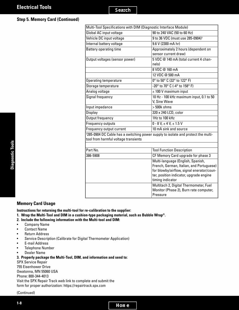
257-9140 Fluke 87V MultimeterWarranty: Manufacturer’s Limited Lifetime
European Union compliant, CE marked• Replaces discontinued 9U-7330 Fluke 87-3 Multimeter• Used to test and adjust electronic circuits• Improved measurement functions, troubleshooting features, resolution, and
accuracy to solve more problems on motor drives or electro-mechanical equip-ment
• Built-in thermometer allows temperature readings without using additional equipment (Type K Thermocouple)
• Selectablefilterforaccuratevoltageandfrequencymeasurementsonmotordrives
• Large-digitdisplaywithbrighttwo-levelbacklightmakesitsignificantlyeasierto read than older models
• Min/Max and average recording to capture variations automatically• Removable holster with built-in test lead and probe storage• Optional magnetic hanger for easy setup and viewing while freeing your hands
for other tasks• Improved sleep mode for long battery life• Inputs are protected to Category III, 1000V, and Category lV 600V to withstand
impulses in excess of 8000V and reduce risks related to surges and spikes• Includes basic test leads, alligator clips, and bead-type thermocouple probe• Complete with 9V battery, Getting Started Manual, and CD with detailed instruc-
tion manualSize 201 x 98 x 52 mm (7.9 x 3.9 x 2.1 in) with
holsterWeight 624 g (22 oz) with holsterBattery life 400 hours typical using 1U-9534 Alkaline
9V
Part Number Description257-9140 Fluke 87V Multimeter
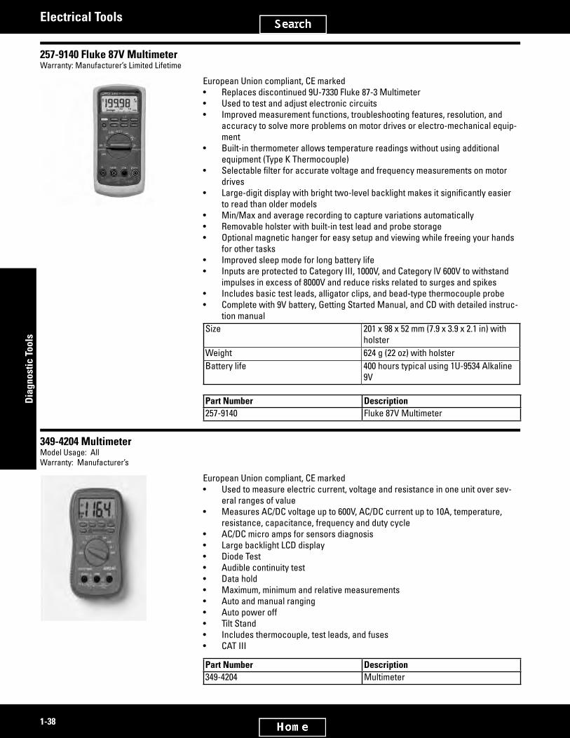
349-4204 MultimeterModel Usage: AllWarranty: Manufacturer’s
European Union compliant, CE marked• Used to measure electric current, voltage and resistance in one unit over sev-
eral ranges of value• Measures AC/DC voltage up to 600V, AC/DC current up to 10A, temperature,
resistance, capacitance, frequency and duty cycle• AC/DC micro amps for sensors diagnosis• Large backlight LCD display• Diode Test• Audible continuity test• Data hold• Maximum, minimum and relative measurements• Auto and manual ranging• Auto power off• Tilt Stand• Includes thermocouple, test leads, and fuses• CAT III
Part Number Description349-4204 Multimeter

2753159
2826351
1-39
Diagnostic Tools
Electrical Tools
Repair InformationFlukePhone: (888) 993-5853
Function Range and Resolution Basic AccuracyDC volts 600.0 mV, 6.000 V, 60.00 V, 600.0 V, 1000 V 0.05%AC volts 600.0 mV, 6.000 V, 60.00 V, 600.0 V, 1000 V 0.7% (True-RMS)DC current 600.0 μA, 6000 μA, 60.00 mA, 600.0 mA,
6.000 A, 10.00 A0.2%
AC current 600.0 μA, 6000 μA, 60.00 mA, 600.0 mA, 6.000 A, 10.00 A
1.0% (True-RMS)
Unit’s temperature rating -200° to 1090° C (-328° to 1994° F) 1.0%Temperature probe rating -40° to 260° C (-40° to 500° F) 2.2° C or 2%Resistance 600.0 Ω, 6.000 kΩ, 60.00 kΩ, 600.0 kΩ,
6.000 MΩ, 50.00 MΩ0.2%
Capacitance 10.00 nF, 100.0 nF, 1.000 μF, 10.00 μF, 100.0 μF, 9,999 μF
1.0%
Frequency 199.99 Hz, 1.9999 kHz, 19.999 kHz, 199.99 kHz
0.005%
ReplacementEuropean Union compliant, CE markedReplacement Fuses ¹3N-5612Voltage rating 600 VCurrent rating 1 ASize (diameter) 10.3 x 34.9 mm (13/32 x 1 3/8 in)Load carrying capacity 110%loadindefinitely,opensat135%loadwithin1hour171-5207 Fuse (11A)Voltage rating 1000 VCurrent rating 11 ASize 10.3 mm diameter x 38.1 mm (13/32 in diameter x 1 1/2 in)Load carrying capacity 110% load 4 hours, opens at 135% load within 1 hour171-5209 Fuse (440 mA)Voltage rating 1000 VCurrent rating 15 ASize 10.3 mm diameter x 34.9 mm (13/32 in diameter x 1 3/8 in)Load carrying capacity 110% load 4 hours, opens at 135% load within 1 hourShort circuit interruption 100,000 A at 600 VAC¹Alsofitsdiscontinued9U-7330Fluke87Multimeterandothers

2828589
2579623
2579644
1-40
Dia
gnos
tic T
ools
Electrical Tools
329-9303 Fluke 355 True-RMS 2000Model Usage: EPG InstallationsWarranty: Manufacturer’s Limited Lifetime
• Auto-ranging and auto-zeroing ohms, continuity and frequency measurements• Category IV 600V and Category III 1000V• Replaces 227-4324 Clamp-on MultimeterSpecificationsDimensions 300 x 98 x 52 mm (12 x 3.75 x 2 in)Frequency Range DC and 10 Hz to 1 kHzCurrent Range 0 to 2000 A AC or DCVoltage Range 0 to 1000 VDC or 0 to 600 VACResistance Range 0 to 400 K ohms
Part Number Description329-9303 Fluke 355 True - RMS 2000
317-9760 Relay TesterEssential ToolSMCS Code: 1400-038Model: Any Cat® equipment with relays listed belowWarranty: Manufacturer’s (One Year)
• Used to diagnose faulty 12V and 24V relays (checks one at a time)• Portabledesignisgreatforfielduse• Designed to test square “ice cube” style relays such as 3E-6477, 3E-9362, 265-
8025, 146-9439, 248-2841, 140-9378, 158-5089, 3E-5239, and 115-1615• Test relays with various terminal arrangements using one of four different con-
nectors• Checks normally OPEN and normally CLOSED relays, with and without resister
or diode• Powered by two 1U-9534 Batteries, 9 Volt• Controls include voltage slide switch, relay energize test button, and position
No. 1 and No. 2 circuit test lamps
Part Number Description317-9760 Relay Tester
244-1536 Corrosion Cable GroupModel: Marine EnginesWarranty: One Year
• Used to determine if metal parts exposed to sea water, within an engine, are subject to corrosion
• Used with 257-9140 Multimeter• Checks low level voltage by clipping black cable to metal part and placing silver
probe into sea water inside the component• Determines if zinc levels are low, good, or too high — proper levels of zinc
extend service life of all parts exposed to sea waterProbe (Red) 6 m (20 ft) longAlligator Probe (Black) 3 m (10 ft) long
Part Number Description244-1536 Corrosion Cable Group

2579662
2579680
2579721
1-41
Diagnostic Tools
Electrical Tools
276-7273 Cylinder Position Sensor Test BoxSMCS Code: 1400-081Model: Models using hydraulic cylinder position sensorsWarranty: One Year
• Used to troubleshoot cylinder position sensors• Used with digital multimeter to read duty cycle, frequency, and voltage• Compactdesignforuseinthefield• Internal 1U-9534 9V battery powers position sensorReferencesREHS2553, Guideline for Reusable Parts and Salvage OperationNEHS0993, Tool Operating ManualOverall size 76.2 x 50.8 x 38.1 mm (3.0 x 2.0 x 1.0 in)Cable length 1.83 m (6 ft)Material Plastic
Part Number Description276-7273 Cylinder Position Sensor Test Box
275-9936 Voltmeter LeadsModel: All modelsWarranty: Six Months
• Push-button generates a load in an electrical circuit so a load test (voltage drop test) can be made with component removed
• Use up 28.5 volts (DC or AC) only• Maximum 5 to 8 seconds per test• Not for computer (ECM) INPUT circuits• Not designed for high voltage circuits• Do not use positive probe in negative side of circuit• Use only with a digital voltmeter• Will not function with ammeter or ohmmeter
Part Number Description275-9936 Voltmeter Leads
152-7213 Fluke123 Scopemeter 120 VACModel: All ModelsWarranty: Manufacturer’s (3 years parts and labor)
• For 220 VAC operation, order optional 138-1154 Battery Charger• Used to test and adjust electronic circuits• Dual channel digital scope and dual channel true-RMS DMM• Fully integrated — always displays scope waveforms and meter readings• Battery life of up to 5 hours• AUTO key for fast, rock stable waveform display of signals down to 1 Hz• Save and recall feature for screen setups• Integral holster stands up to rough treatment• User assistance in English and Spanish• Brilliant high contrast backlit LCD• Hardened scratch-resistant lens protects LCD from damage• Unique shielded test lead for all measurements• All measurement terminals are isolated from earth ground• Usedtorecordtrendsandfindintermittentsusingdual-channelTrendPlot
(Continued)

2579721
1-42
Dia
gnos
tic T
ools
Electrical Tools
152-7213 Fluke123 Scopemeter 120 VAC (Continued)Model: All ModelsWarranty: Manufacturer’s (3 years parts and labor)
Comes fully equipped with:• BP 120 Rechargeable battery pack (installed)• PM 8907 line voltage adapter/charger — 120 volt AC, 50/60 Hz only• 2 STL 120 shielded test leads (1 red, 1 gray; which includes 2 ground leads)• 1 black TL75 test lead• 2 HC 120 Hook Clips• 3 AC 120 Alligator clips• 1 BB 120 Shielded Banana to BNC adapter• User’s Manual
Part Number Description Size Weight152-7213 Fluke 123 Scopemeter 120 VAC 50 x 115 x 232 mm (2 x 4.5 x 9.1 in) 1 kg (3 lb)
Repair InformationFlukePhone: (888) 993-5853
GeneralSpecificationsDisplayColdcathodefluorescentbacklitLCD.Contrastandbrightnessuseradjustable.Wideviewingangle.Size 72 x 72 mm (2.8 x 2.8 in)PowerLine voltage adapter/battery charger included (120 VAC, 50/60 Hz)For 220 VAC operation, order optional 138-1154 Battery ChargerInstalled battery Rechargeable NiCd packOperating time Up to 5 hoursCharging time 4 hoursEnvironmentalTemperature 0° to 50° CEnvironmental MIL-T-28800E, Type III, Class 3, Style BElectro-Magnetic CompatibilityEmission EN50081-1 (1992): EN55022 and EN60555-2Immunity EN50082-2 (1992): IEC1000-4, -2, -3, -5Enclosure protection IP51, IEC529 (dust, drip proof)Mechanical DataSize 50 x 115 x 232 mm (2 x 4.5 x 9.1 in)Weight 1.2 kg (2.5 lb)SafetyDesigned for measurements on 600V Overvoltage Category III Installations, Pollution Degree 2, per:ANSI/ISA S82.01-1994, EN61010.1 (1993) (IEC1010-1), CAN/CSA-C22.2 No. 1010.1-92, UL3111-1Surge protection 6 kV on input A and BFloating measurements 600 V RMS from any terminal to groundOptically Isolated RS-232 InterfaceTo printer Supports HP LaserJet®, DeskJet®, Epson FX/LQ, and Postscript
To PC Dump and load settings and data, compatible with FlukeView® Software SW90W/012E for Windows

2753298
1-43
Diagnostic Tools
Electrical Tools
Dual Input 5000 Count Autoranging Meter
DC Voltage VDCRanges 500 mV, 5 V, 50 V, 500 V, 1250 VAccuracy ±(0.5% + 5 counts)True RMS Voltage VAC and VAC+DCRanges 500 mV, 5 V, 50 V, 500 V, 1250 VAccuracy ±(1% + 10 counts)Additional Measurements and FunctionsOhms, Continuity, Diode Test, Amps, °C or °F, Capacitance, dBV, dBM, Crest Factor, Touch Hold, and Zero Set. (Amps, °C or °F with optional probes)TrendPlot™Graphs meter readings of the MIN and MAX values from 120 seconds to 16 days. Automatic vertical scaling and time compres-sion. Displays the actual and MIN, MAX or AVG reading. Dual Input OscilloscopeVerticalBandwidth 20 MHz at inputs with STL120 1:1 leads 12.5 MHz with PM 8918 10:1 optional probes 20 MHzCoupling AC, DCSensitivity 5 mV/div - 500 V/divVertical resolution 8 bitAccuracy ±(2% of reading + 0.05 x range/div) HorizontalRange 20 ns/div - 60 s/divAcquisition modes Normal, single, roll, envelope, smoothMax. sample rate 1.25 GS/s for repetitive signals 25 MS/s for single shotRecord length 512 samples per channelAccuracy ±(0.1% of reading + 0.04 x time/div)Glitch capture 40 ns or longer TriggerSource A or B. External via optional ITP120Modes Auto, triggered, singleVideo NTSC, PAL, PAL+, SECAM random lines or user selectable linePre-trigger Up to 10 division of pre-trigger view MeasurementsVDC, VAC, VAC+DC, Vpeak, Vpeak-peak, Frequency, Duty Cycle, Pulse Width and Phase. Measurements can be scaled to A. MemoryType of memory 2 screens, 10 user setups

2643695
2579783
1-44
Dia
gnos
tic T
ools
Electrical Tools
138-1154 Power Adapter, 220 volt• Used to connect 152-7213 Fluke 123 Scopemeter to a 220 volt AC utility power
supply• Sold separatelyInput volts 115 VAC ± 10% or 230 VAC ± 15%Line frequency 50, 60, 400 Hz ± 10%Output voltage 15 VDCOutput current 300 mA maximumPower consumption 7 W maximumOutput plug 5 mm power jack per DIN 45232Operating temperature 0° to 40° C (0° to 104° F)Input plug Standard 110 V
Part Number Description138-1154 Power Adapter, 220 Volt
228-3175 Calibrator GroupSMCS Code: 7002-038, 0778-035Model: 3600 Generator SetWarranty: Manufacturer’s Three Year
European Union compliant, CE marked• 220 VAC use only (international only)• Used to source/measure temperature and electrical signals with precise accuracy, all in one rugged, hand-held device• Used to calibrate 3600 Protection Systems, Marine Monitoring Systems, 3600 Engine Management Systems, 3600 Electronic
Unit Injection Systems, and 3600 Custom PLC Systems• Automatically captures calibration results• Measures/simulates eleven different types of thermocouples and eight different RTD’s• Stores up to 8,000 readings• Unit is protected against dirt, dust, vibration, and moisture• Operates in English, French, German, Italian, or Spanish• Equipped with a built-in calculator• Comes with a three-year warranty• ComeswithISO9001CalibrationCertificate• Calibrator includes: 2 sets of test leads, 2 sets of alligator clips, 1 set of probe leads, 1 Nickel-Cadmium 7.2 volt battery, 1
battery charger, 1 carrying strap, 2 jumper leadsRepair InformationFlukePhone: (888) 993-5853Dimensions (W x D x H) 130 x 61 x 236 mm (5.1 x 2.4 x 9.3 in)Weight 1.4 kg (3.06 lb)Display 240 by 200 pixel graphic LCDMemory backup Lithium battery, 5 years typical lifetimeOperating temperature -10° to 50° C (14° to 122° F)Storage temperature -20° to 60° C (-4° to 140° F)
Part Number Description228-3175 Calibrator Group
Service/Repair Parts163-0097 Battery8T-0458 Wire - Thermocouple

3037180
1-45
Diagnostic Tools
Electrical Tools
396-4789 Fluke 753 CalibratorModel Usage: 3600 Generator Sets, MarineWarranty: Manufacturer’s
European Union Compliant, CE marked• Used to source/simulate volts, mA, thermocouples, RTDs, frequency, ohms, and
pressure calibrate transmitters• Automatically records and documents calibration results• Measure and source simultaneously with one compact, rugged, reliable tool• Stores up to 8000 readings• Operates in English, French, German, Italian and Spanish• Comes with three-year warranty• Used to calibrate 3600 Protection Systems, Marine Monitoring Systems, 3600
Engine Management Systems, 3600 Electronic Unit Injector Systems and 3600 Custom PLC Systems
• Includes Battery Charger & Li-ion Battery PackSpecificationsDimensions 245 x 134 x 63 mm (9.6 x 5.3 x 2.5 in)Weight 1.2 kg (2.7 lb)Batteries 7.2 V, 4400 mAh, 30 Wh, Internal battery
pack Li-ionOperating Temperature -10 to 50°C (14 to 122°F)Storage Temperature -20 to 60°C (-4 to 140°F) Service/Repair Parts396-4790 Battery Charger: 146 x 76 x 64 mm (2.8 x
3 x 2.5 in)396-4791 Li-ion Battery Pack: 152 x 7 x 25 mm (6 x
2.8 x 1 in)

3037399
3037408
1-46
Dia
gnos
tic T
ools
Electrical Tools
Technical Data
Data Log Functions Measure functions: Voltage, current, resistance, frequency, temperature, pressure
Reading rate: 1, 2, 5, 10, 20, 30, or 60 readings/minute Maximum record length: 8000 readings (7980 for 30 or 60 read-
ings/minute)Ramp Functions Source functions: Voltage, current, resistance, frequency,
temperature Rate: 4 steps/second Trip detect: Continuity or voltage (continuity detectionnot avail-
able when sourcing current)Loop Power Function Voltage: Selectable, 26 V Accuracy: 10%, 18 V minimum at 22 mA Maximum current: 25 mA, short circuit protected Maximum input voltage: 50 V DCStep Functions Source functions: Voltage, current, resistance, frequency,
temperature Manual Step: Selectable step, change with arrow buttons Autostep: Fully programmable for function, start delay, step
value, time per step, repeatSafetySpecificationsAgency Approvals CAN/CSA C22.2 No 1010.1-92, ASNI/ISA S82.01-1994, UL3111,
and EN610-1:1993
Measurement Accuracy
Voltage DC 1 Year 2 Years 100.000 mV 0.02% + 0.005 mV 0.03% + 0.005 mV 3.00000 V 0.02% + 0.00005 V 0.03% + 0.00005 V 30.0000 V 0.02% + 0.0005 V 0.03% + 0.0005 V 300.00 V 0.05% + 0.05 V 0.07% + 0.05 V Voltage AC Range 40 to 500 Hz Resolution 1 Year 2 Years 3.000 V 0.001 V 0.5% + 0.002 V 1.0% + 0.004 V 30.00 V 0.01 V 0.5% + 0.02 V 1.0% + 0.04 V 300.0 V 0.1 V 0.5% + 0.2 V 1.0% + 0.2 VCurrent DC 1 Year 2 Years 30.000 mA 0.01% + 5 uA 0.015% + 7 uA 110.00 mA 0.01% + 20 uA 0.015% + 30 uA Resistance 1 Year 2 Years 10.000 Ω 0.05% + 50 mΩ 0.07% + 70 mΩ 100.00 Ω 0.05% + 50 mΩ 0.07% + 70 mΩ 1.0000 kΩ 0.05% + 500 mΩ 0.07% + 0.5 Ω 10.000 kΩ 0.1% + 10 Ω 0.15% + 15 Ω Frequency Resolution Accuracy (2 Years) 1.00 to 110.00 Hz 0.01 Hz 0.05 Hz 110.1 to 1100.0 Hz 0.1 Hz 0.05 Hz 1.101 to 11.000 kHz 0.001 kHz 0.005 kHz 11.01 to 50.00 kHz 0.01 kHz 0.05 kHz

3037416
2753477
1-47
Diagnostic Tools
Electrical Tools
Source Accuracy
Voltage DC 1 Year 2 Years 100.000 mV 0.01% + 0.005 mV 0.015% + 0.005 mV 1.00000 V 0.01% + 0.00005 V 0.015% + 0.0005 V 15.0000 V 0.01% + 0.0005 V 0.015% + 0.0005 VCurrent DC 1 Year 2 Years 22.000 mA (Source) 0.01% + 0.003 mA 0.02% + 0.003 mA Current Sink (Simulate) 0.02% + 0.007 mA 0.04% + 0.007 mAResistance 1 Year 2 Years 10.000 Ω 0.01% + 10 mΩ 0.015% + 15 mΩ 100.00 Ω 0.01% + 20 mΩ 0.015% + 30 mΩ 1.0000 kΩ 0.02% + 0.2 Ω 0.023 + 0.3 Ω 10.000 kΩ 0.02% + 3 Ω 0.03% + 5 ΩFrequency 2 Years 0.1 to 10.99 Hz 0.01 Hz 0.01 to 10.99 Hz 0.01 Hz 11.00 to 109.99 Hz 0.1 Hz 110.00 to 1099.9 Hz 0.1 Hz 1.100 to 21.999 kHz 0.002 kHz 22.000 to 50.000 kHz 0.005 kHz
RTD’s and Thermocouples
RTD’s and ThermocouplesDevice Measure Accuracy Source Accuracy10 Cu (427) 3° C 1° C100 Pt (3916) 0.3° C 0.1° C100 Pt (3926) 0.3° C 0.1° C100 Pt (385) 0.3° C 0.1° C200 Pt (385) 0.3° C 0.1° C500 Pt (385) 0.3° C 0.1° C1000 Pt (385) 0.3° C 0.1° C120 Ni (672) 0.3° C 0.1° CE 0.3° C 0.2° CN 0.5° C 0.3° CJ 0.3° C 0.2° CL 0.3° C 0.2° CK 0.3° C 0.3° CT 0.3° C 0.3° CU 0.3° C 0.3° CB 0.9° C 0.8° CR 1.0° C 0.9° CS 0.9° C 0.9° CC 0.6° C 0.6° CResolution: 0.1° C, except 1° C for 10 Cu. Best case, mid-range accuracies. Sensor inaccuracies not included. For 2-wire and 3-wire RTD measurements, add 0.4° C. Thermocouple accuracies with external cold junction. For internal add 0.2° C.
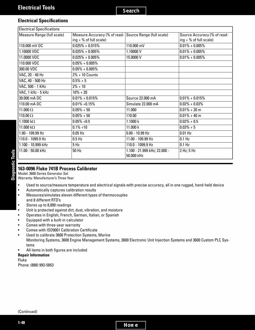
2753446
2826433
1-48
Dia
gnos
tic T
ools
Electrical Tools
Electrical Specifications
ElectricalSpecificationsMeasure Range (full scale) Measure Accuracy (% of read-
ing + % of full scale)Source Range (full scale) Source Accuracy (% of read-
ing + % of full scale)110.000 mV DC 0.025% + 0.015% 110.000 mV 0.01% + 0.005%1.10000 VDC 0.025% + 0.005% 1.10000 V 0.01% + 0.005%11.0000 VDC 0.025% + 0.005% 15.0000 V 0.01% + 0.005%110.000 VDC 0.05% + 0.005% 300.00 VDC 0.05% + 0.005% VAC, 20 - 40 Hz 2% + 10 Counts VAC, 40 - 500 Hz 0.5% + 5 VAC, 500 - 1 KHz 2% + 10 VAC, 1 kHz - 5 kHz 10% + 20 30.000 mA DC 0.01% + 0.015% Source 22.000 mA 0.01% + 0.015%110.00 mA DC 0.01% +0.15% Simulate 22.000 mA 0.02% + 0.03%11.000 Ω 0.05% + 50 11.000 0.01% + 20 m110.00 Ω 0.05% + 50 110.00 0.01% + 40 m1.1000 kΩ 0.05% +0.5 1.1000 k 0.02% + 0.511.000 kΩ 0.1% +10 11.000 k 0.03% + 51.00 - 109.99 Hz 0.05 Hz 0.00 - 10.99 Hz 0.01 Hz110.0 - 1099.9 Hz 0.5 Hz 11.00 - 109.99 Hz 0.1 Hz1.100 - 10.999 kHz 5 Hz 110.0 - 1099.9 Hz 0.1 Hz11.00 - 50.00 kHz 50 Hz 1.100 - 21.999 kHz; 22.000 -
50.000 kHz2 Hz; 5 Hz
163-0096 Fluke 741B Process CalibratorModel: 3600 Series Generator SetWarranty: Manufacturer’s Three Year
• Used to source/measure temperature and electrical signals with precise accuracy, all in one rugged, hand-held device• Automatically captures calibration results• Measures/simulates eleven different types of thermocouples
and 8 different RTD’s• Stores up to 8,000 readings• Unit is protected against dirt, dust, vibration, and moisture• Operates in English, French, German, Italian, or Spanish• Equipped with a built-in calculator• Comes with three-year warranty• ComeswithISO9001CalibrationCertificate• Used to calibrate 3600 Protection Systems, Marine
Monitoring Systems, 3600 Engine Management Systems, 3600 Electronic Unit Injection Systems and 3600 Custom PLC Sys-tems
• AllitemsinbothfiguresareincludedRepair InformationFluke Phone: (888) 993-5853
(Continued)

2826433
1-49
Diagnostic Tools
Electrical Tools
163-0096 Fluke 741B Process Calibrator (Continued)Model: 3600 Series Generator SetWarranty: Manufacturer’s Three Year
Dimensions (W x D x H): 130 x 61 x 236 mm (5.1 x 2.4 x 9.3 in)Weight: 1.4 kg (3.06 lb)Display: 240 x 200 pixel graphic LCDMemory backup: Lithium battery, 5 years typical lifetimeOperating temperature: -10° to 50° C (14° to 122° F)Storage temperature: -20° to 60° C (-4° to 140° F) RTD’s and ThermocouplesDevice Measure Accuracy Source Accuracy10 Cu (427) 3° C 1° C100 Pt (3916) 0.3° C 0.1° C100 Pt (3926) 0.3° C 0.1° C100 Pt (385) 0.3° C 0.1° C200 Pt (385) 0.3° C 0.1° C500 Pt (385) 0.3° C 0.1° C1000 Pt (385) 0.3° C 0.1° C120 Ni (672) 0.3° C 0.1° CE 0.3° C 0.2° CN 0.5° C 0.3° CJ 0.3° C 0.2° CL 0.3° C 0.2° CK 0.3° C 0.3° CT 0.3° C 0.3° CU 0.3° C 0.3° CB 0.9° C 0.8° CR 1.0° C 0.9° CS 0.9° C 0.9° CC 0.6° C 0.6° CResolution: 0.1° C, except 1° C for 10 Cu. Best case, mid-range accuracies. Sensor inaccuracies not included. For 2-wire and 3-wire RTD measurements, add 0.4° C. Thermocouple accuracies with external cold junction. For internal add 0.2° C.

2643419
2753592
1-50
Dia
gnos
tic T
ools
Electrical Tools
Calibrator Electrical Specifications
ElectricalSpecificationsMeasure Range (full scale)
Measure Accuracy (% of reading + % of full scale)
Source Range (full scale)
Source Accuracy (% of reading + % of full scale)
110.000 mV DC 0.025% + 0.015% 110.000 mV 0.01% + 0.005%1.10000 VDC 0.025% + 0.005% 1.10000 V 0.01% + 0.005%11.0000 VDC 0.025% + 0.005% 15.0000 V 0.01% + 0.005%110.000 VDC 0.05% + 0.005% 300.00 VDC 0.05% + 0.005% VAC, 20 to 40 Hz 2% + 10 Counts VAC, 40 to 500 Hz 0.5% + 5 VAC, 500 to 1 KHz 2% + 10 VAC, 1 kHz to 5 kHz 10% + 20 30.000 mA DC 0.01% + 0.015% Source 22.000 mA 0.01% + 0.015%110.00 mA DC 0.01% +0.15% Simulate 22.000 mA 0.02% + 0.03%11.000 Ω 0.05% + 50 11.000 0.01% + 20 m110.00 Ω 0.05% + 50 110.00 0.01% + 40 m1.1000 kΩ 0.05% +0.5 1.1000 k 0.02% + 0.511.000 kΩ 0.1% +10 11.000 k 0.03% + 51.00 to 109.99 Hz 0.05 Hz 0.00 to 10.99 Hz 0.01 Hz110.0 to 1099.9 Hz 0.5 Hz 11.00 to 109.99 Hz 0.1 Hz1.100 to 10.999 kHz 5 Hz 110.0 to 1099.9 Hz 0.1 Hz11.00 - 50.00 kHz 50 Hz 1.100 - 21.999 kHz;
22.000 - 50.000 kHz2 Hz; 5 Hz
Parts
Item Description Qty.1 Test Leads 2 sets2 Alligator Clips 2 sets3 Probe Leads 1 set4 Nickel-Cadmium 7.2 V
Battery1
5 Battery Charger 16 Carrying Strap 17 Jumper Leads 2
Part Number Description163-0096 Fluke 741B Process Calibrator
Service/Repair Parts163-0097 Battery8T-0458 Wire - Thermocouple

2579840
2579857
2579875
1-51
Diagnostic Tools
Electrical Tools
1U-8115 Insulated Tip Test Lead SetModel: All ModelsWarranty: One Year
• Optional accessory lead set for multimeters which have 9.5 mm (0.375 in) diam-eter input connectors; older meters have larger diameter connectors
• Spring loaded insulators over metal probe tips to prevent tips from making ac-cidental electrical contact with wires and terminals during testing; accidental electrical contact can be a problem when reaching into electrical circuitry with normal test leads which have as much as 19 mm (0.75 in) of bare probe exposed; on 1U-8115 Test Lead probes, only very tip of probe normally exposed
• However, since insulating sleeves are spring loaded, they can be pushed back at any time to expose more of metal tip; allows metal probe tip to enter small diameter holes when testing connectors; insulators can be pushed back and locked in position to uncover approximately 6.3 mm (0.25 in) of bare probe
Lead length 1378 mm (54 in)Connectors 9.5 mm (0.375 in) diameter shielded
banana plugMaximum voltage rating 700 VAC or VDCColor 1 red and 1 black leadProbe tip diameter 1.77 mm (0.070 in)Probe tip length 15 mm (0.6 in) maximum
Part Number Description1U-8115 Insulated Tip Test Lead Set
152-7143 Cable Assembly (GSC Data Cable)SMCS Code: 4450-038Model: Generator SetsWarranty: One Year
• Usedtoflash-programEMCP2+GeneratorStatusControl(GSC)module• Used with universal communications adapter cable (139-4166)• Requires Cat® ET and communication adapter (171-4400 or discontinued 7X-
1700)• Flash-programmingonlyusedforfieldupdates
Part Number Description152-7143 Cable Assembly (GSC Data Cable)
4C-4029 Trimmer Adjustment ToolModel: All ModelsWarranty: Six Months
• Allows easier adjustment of small screwdriver adjustments found on VR3 and VR4 Voltage Regulators and 2301 Woodward Regulator Controls
• Constructedofglass-filled,nylonbodywithstainlesssteelblades;oneendhasrecessed blade to provide captive screwdriver for adjustments that are dif-ficulttosee;otherendhasexposedbladetoreachadjustmentsthatarebehindpanels and have small access holes
(Continued)

2579875
2579893
2579918
1-52
Dia
gnos
tic T
ools
Electrical Tools
4C-4029 Trimmer Adjustment Tool (Continued)Model: All ModelsWarranty: Six Months
• Gain and level controls on VR3 Voltage Regulator are inside regulator case and difficulttoadjustwhengeneratorsetisinoperation;inabilitytoseethecontrolandvibrationofregulatormakefineadjustmentsverydifficult
• Prevents broken controls on Woodward 2301 Controls caused by improper tool usage and excessive force required for adjustment when wrong tool is used
Part Number Description4C-4029 Trimmer Adjustment Tool
189-1720 Analog Gauge Tester GroupModel: All ModelsWarranty: One Year
• Used to test and troubleshoot analog temperature, pressure, fuel or articulation gauges
• Easy-to-use, hand-held unit• ToolOperatingManualincludeschartsforspecificgauges• Decrease troubleshooting time and reduce cost by eliminating replacement of
good parts• Diagnose temperature, fuel or pressure gauge problems to determine if gauge,
wiring or sender is faulty• 0 to 50, 500, 1500 and 34,000 ohm dials used in combination to simulate senders
output• Fuse protected from electrical overload• Not for use with the Cat® Quad Gauge Module• Resistance tolerance: ±10% at full scale• Linearity tolerance: ±5% independent• GroupincludesallitemsinfigureReferenceNEHS0786, Tool Operating Manual
Part Number Description189-1720 Analog Gauge Tester Group
4C-4693 Tester Group, VR3 and VR4 RegulatorModel: All ModelsWarranty: One Year
• Supplies voltages necessary to check all styles of VR3 and VR4 regulators; serviceman selects correct sense voltage
• Operates from 110/220 volt AC source• Uses100wattlightbulbasloadforfieldcurrent• Hastestportstomeasuresensevoltageandfieldvoltagewithprobessupplied
with Cat® multimeter• AllitemsinfigureareincludedReferenceNEHS0535, Tool Operating Manual
Item Part Number DescriptionAll Items 4C-4693 Tester Group, VR3 and VR4
Regulator1 4C-4529 Line Cord2 4C-4694 Cable Assembly

2817652
2579939
2579952
1-53
Diagnostic Tools
Electrical Tools
Voltage
Input voltage 110/220 VAC, 50/60 HzOutput voltage Variable from 0 VAC to 20% over selected Sense voltageOutput voltage 0 VAC to 80 VAC (PM supply only)Sense voltage 120 VAC, 240 VAC or 480 VAC
FT1488 Exciter Tester GroupSMCS Code: 1404-036Model: SR-4 and SRCR GeneratorsWarranty: None
• Used to test regulator-exciter control assemblies on SR-4 and SRCR Generators• Drawing provides complete details for assembling bench tester which will simi-
late generator for repairing exciter in the shop
309-9888 USB Adapter Cable309-9891 Serial (RS232) Adapter CableModel: Forestry Products - Feller BunchersWarranty: 12 Month Manufacturer’s
• Adapter cables used to service, troubleshoot, and reprogram IQAN Parker elec-tronic control modules from a personal computer (PC)
309-9888 USB Adapter Cable• Used to troubleshoot and reprogram electronic control modules• Used with “IQANrun” software programs• PC software available from Media Logistics — NETG5038309-9891 Serial Adapter Cable• Used to service electronic control modules• Used with “IQANdevelop” software program• PC software available from Media Logistics — NETG5037
Part Number Description309-9888 USB Adapter Cable309-9891 Serial (RS232) Adapter Cable

2579974
2753751
1-54
Dia
gnos
tic T
ools
Electrical Tools
309-9893 Tool KitModel: Forestry ProductsWarranty: 12 Month Manufacturer’s
• Used to repair IQAN receptacles and plugs used on Parker electronic control modules
• Tool kit includes crimp tools, extraction tools, and all ter-minals necessary for repairing connector assemblies
• 309-9895 Terminal Kit (part of 309-9893 Tool Kit) is also available as a serviceable part
ReferenceNEHS1023, Crimp Tool Operating ManualItem DescriptionRed Crimp Tool Crimping JPT (Junior Power
Timer), with sealYellow Crimp Tool Crimping JPT (Junior Power
Timer), no sealBlue Crimp Tool Crimping Microtimer (with
seal/no seal)Red Extraction Tool Extracts single-locking tab
Junior Power Timer pinsYellow Extraction Tool Extracts double-locking tab
Junior Power Timer pinsBlue Extraction Tool Extracts double-locking tab
Microtimer pinsTerminal Kit (See other chart for included
items)
Part Number Description309-9893 Tool Kit
Terminal Kit
309-9895 Terminal KitItem Specification Qty.Microtimer (no seal) 18-20 AWG (0.75 mm²) 100Microtimer (with seal) 18-20 AWG (0.75 mm²) 100Microtimer Cavity Plug — 100Microtimer Seal — 100JPT (no seal) 18-20 AWG (0.75 mm²) 50JPT (no seal) 14-16 AWG (1.5 mm²) 25JPT (with seal) 14-16 AWG (1.5 mm²) 25JPT (with seal) 18-20 AWG (0.75 mm²) 50JPT (with seal) 18-20 AWG (0.75 mm²) 25JPT Cavity Plug — 25JPT Seal 18-20 AWG (0.75 mm²) 50JPT Seal 14-16 AWG (1.5 mm²) 25

2828755
2828378
2828416
1-55
Diagnostic Tools
Electrical Tools
369-4181 Ampseal Connector Perimeter Seal KitSMCS Code: 1408-023Model Usage: Electronic EnginesWarranty: 1 Year
Tool Description:• Replacement seals for all AMPSEAL connectors• A damaged perimeter seal can allow moisture and dirt to affect mated connec-
tions• Replacement perimeter seals are made of colored silicone rubber
Part Number Description Color/Size Quantity369-4181 Ampseal Connector
Seal Kit— 1
4C-4787 Utility Box (9 compart-ment, plastic)
7 x 3.75 x 1.24 in (178 x 95 x 31 mm)
1
264-7029 2-pin connector seal Red 25264-7030 3-pin connector seal Yellow 25264-7031 4-pin connector seal Yellow 25264-7032 6-pin connector seal Red 25264-7033 8-pin connector seal Yellow 25264-7034 12-pin connector seal Yellow 25
360-3122 Extension Lead GroupSMCS Code: 1400-081Warranty: Manufacturer’s
• Used to extend leads to provide a longer reach from multimeter.• Used with 257-9140 Fluke 87V Multimeter and 157-7213 Fluke 123 Scopemeter• Includes one pair of color-coded (red/black) silicone insulated leads 1.5m (5.0 ft) long• Two color-coded female couplers (included) allow two sets of 360-3122 Extension Leads to be connected together• 600V CAT IV, 1000 V CAT III, 10A rating• UL Listed
Part Number Description360-3122 Extension Lead Group
Electrical Diagnostic ToolsEssential ToolSMCS Code: 1000-038, 1050-38, 1400-038, 1400-081, 1450-038Model: 795F AC Off-Highway TruckWarranty: Manufacturer’s
331-6561 High Voltage Meter (North America Only)• Used to measure Voltage• Digital Voltmeter with removable handles has 10.2mm (.4 in) LCD backlit display• Voltmeter features timed auto shut-off to extend battery life• Unit will shut off or not operate if battery is low• A 9 Volt battery powered voltmeter proff tester with 500V output is included• Unitcomeswithtwo20cm(8in)fixedlengthfiberglasshotsticks• Includes 9 Volt Alkaline batteries, carry case with foam insert, and calibration
instruction manual
(Continued)
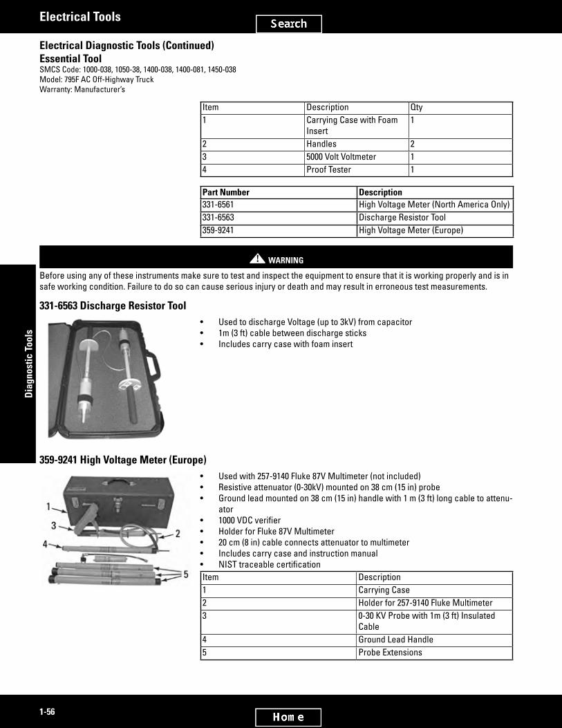
2828416
2828429
1-56
Dia
gnos
tic T
ools
Electrical Tools
Electrical Diagnostic Tools (Continued)Essential ToolSMCS Code: 1000-038, 1050-38, 1400-038, 1400-081, 1450-038Model: 795F AC Off-Highway TruckWarranty: Manufacturer’s
Item Description Qty1 Carrying Case with Foam
Insert1
2 Handles 23 5000 Volt Voltmeter 14 Proof Tester 1
Part Number Description331-6561 High Voltage Meter (North America Only)331-6563 Discharge Resistor Tool359-9241 High Voltage Meter (Europe)
! WARNING
Before using any of these instruments make sure to test and inspect the equipment to ensure that it is working properly and is in safe working condition. Failure to do so can cause serious injury or death and may result in erroneous test measurements.
331-6563 Discharge Resistor Tool• Used to discharge Voltage (up to 3kV) from capacitor• 1m (3 ft) cable between discharge sticks• Includes carry case with foam insert
359-9241 High Voltage Meter (Europe)• Used with 257-9140 Fluke 87V Multimeter (not included)• Resistive attenuator (0-30kV) mounted on 38 cm (15 in) probe• Ground lead mounted on 38 cm (15 in) handle with 1 m (3 ft) long cable to attenu-
ator• 1000VDCverifier• Holder for Fluke 87V Multimeter• 20 cm (8 in) cable connects attenuator to multimeter• Includes carry case and instruction manual• NISTtraceablecertificationItem Description1 Carrying Case2 Holder for 257-9140 Fluke Multimeter3 0-30 KV Probe with 1m (3 ft) Insulated
Cable4 Ground Lead Handle5 Probe Extensions

2828478
2828499
1-57
Diagnostic Tools
Electrical Tools
349-4198 Phase Meter AssemblySMCS Code: 7002-038, 0778-035Model: Generator SetsWarranty: Manufacturer’s Three Year
European Union compliant, CE marked• Used to test three functions including open phase, phase sequence, and motor rotation• One half of unit measures phase sequence of a 3-wire system using power from system under test
(lamp indicators will indicate 3-phase sequence or an open phase situation)• Other half of unit measures 3-phase motor rotation on a powered or unpowered motor
(indicates whether motor shaft has clockwise or counter-clockwise rotation)• Supplied with three CAT III rated color-coded, large alligator clips and test leads• Rated for CAT III 600V on both testing phase sequence and motor rotation• Conforms to EN61010-1:2001; CAT III 600V, Pollution Degree 2, Class 2; CSA 22.2-1010.1; and EN61557-7• Zippered carrying case for portability• Includes test leads (red, green, and blue) with alligator clips, soft vinyl case, Users Manual, and 9 V batteryBattery Life Approximately 200 hoursBattery Standard 9 VSize 153 x 72 x 35 mm (6.02 x 2.83 x 1.37 in)Weight 218 g (7 oz) including batteryOperating temperature 0 - 40° C (32 - 104° F) Phase Sequence:Input Voltage 3 phase to phase inputs 100 V AC to 600 V AC maximumFrequency range 45 to 70 HzOperating time 10 minutes ON maximum at 600 V AC 10 minutes OFF minimum at 600 V AC3-phase Approximately 7 mA per phase of AC power source Motor Rotation:Operating time 10 minutes ON maximum 10 minutes OFF minimumTesterfield 14 mA of 9 battery
Part Number Description349-4198 Phase Meter Assembly
368-8645 Blowby GroupSMCS Code: 1000-038, 1350-038, 1350-081Model: AllWarranty: One Year
European Union compliant, CE marked• Usedtotrendvolumeofblowbygasesreleasedthroughenginecrankcasebreather(measuresinchesofwateronorifice
tube)• Inputusesconvenientquick-disconnectfitting• Large LCD display with backlighting• Eleven units of measure (user selectable by front panel pushbutton)• Max/Min/Avg recording• Zero function for offset correction or measurement• Advanced features include DATA HOLD, MIN-MAX-AVG RECORD mode, ZERO/OFFSET, AUTO POWER OFF• Built-in USB serial interface• Tool operating manual includes charts to convert readings from inches of water to cubic feet/minute• Uses a 9V battery for power• To conserve battery life, an automatic power off feature turns unit OFF after 20 minutes
(Continued)

2828499
2828541
1-58
Dia
gnos
tic T
ools
Electrical Tools
368-8645 Blowby Group (Continued)SMCS Code: 1000-038, 1350-038, 1350-081Model: AllWarranty: One Year
• Includeslargeandsmallorifices,two1/8-27NPThosebarbfittings,atwofootlong1/8IDx1/4inchODcleartubing,6V-3073 Carrying Case, 6V-4094 Foam Inserts, 368-8645 Lid Decal
Unit of Measure Display IconPounds per square inch psiInches of mercury in HgMilli-bar mbarMillimeters of mercury mm HgKilo-Pascals kPaKilograms per centimeter squared Kg cm²Inches of water in H2OFeet of water ft H2OCentimeters of water cm H2OBars barOunces per square inch oz in²
Part Number Description368-8645 Blowby Group
! WARNING
Pressure inputs of 0.689 Bar (10 psi) or higher will damage the instrument. Do not apply pressure higher than the maximum pres-surelistedinthespecificationchart.
Repair InformationExtech Instruments Corporation9 Townsend WestNashua, NH 03061
Email: [email protected] For repair or calibration, call 781-890-7440, ext: 220 for a Return Authorization Number and shipping instructionsReferenceNEHS1110, Tool Operating ManualUser Guide: Heavy-Duty Differential Pressure Manometer, Model HD700 (OEM manufacturer supplied)
(Continued)

2828541
2889072
1-59
Diagnostic Tools
Electrical Tools
Repair Information (Continued)Extech Instruments Corporation9 Townsend WestNashua, NH 03061
Specifications Range ResolutionkPa / mbar / psi 13.78 / 137.8 / 2 0.01 / 0.1 / 0.001mm Hg / in Hg 103.4 / 4.072 0.1 / 0.001oz in² 32 0.01cm H2O / in H2O / ft H2O 140 / 55.40 / 4.616 0.1 / 0.01 / 0.001kg cm² 0.140 0.001bar 0.137 0.001 Display Four-digit LCD with function indicators Units of Measure bar, mbar, psi, kg/cm², mm Hg, inches Hg,
kPa, feet H2O, inches H2O, cm H2O, and oz in²
Accuracy ± 0.3% FS [@ 25° C (77° F)] Repeatability ± 0.2% to 0.5% FS Linearity / hysteresis ± 0.3% FS Combined accuracy ± 1.1%FS Maximum pressure 0.689 bar (10 psi) Response time 0.5s typical Input circuit Differential inputs (P1 and P2) Input ports Two metal 4.8 mm (.189 in), barbed for
3.17 mm (.125 in) ID tubing
Data hold Freezes displayed reading Sensor Built-in piezoelectric sensors Zero / offset function Pushbutton activation Sample rate 0.5 sec. (approx.) Compatibility Air or non-corrosive and non-ionized gas
(not intended for use with liquids)
Auto power OFF Meter turns off after approx. 20 minutes to conserve energy (can be deactivated)
PC interface Built-in USB serial interface Storage conditions 0 to 60° C (14 to 140° F); < 80% RH Operating conditions 0 to 50° C (32 to 122° F); < 80% RH Battery power 9V alkaline battery (BAT low battery
indicator)
Battery life 125 hours typical Size 30 x 23 x 10 cm (12 x 9 x 4 in) Weight 4.5 kg (9 lb, .9 oz)
Specifications
Specifications Range ResolutionkPa / mbar / psi 13.78 / 137.8 / 2 0.01 / 0.1 / 0.001mm Hg / in Hg 103.4 / 4.072 0.1 / 0.001oz in² 32 0.01cm H2O / in H2O / ft H2O 140 / 55.40 / 4.616 0.1 / 0.01 / 0.001kg cm² 0.140 0.001bar 0.137 0.001

2829015
2969018
1-60
Dia
gnos
tic T
ools
Electrical Tools
377-6198 Harness Braiding CutterModel Usage: All ModelsWarranty: One Year
• Allows operator to easily cut braiding when repairing harnesses• Braiding Cutter includes a safety ball and a safety cap
Part Number Description Dimensions377-6198 Harness Braiding Cutter 5 1/8 in Long
362-3555 Ampseal Style Connector Field Repair KitModel Usage: AllWarranty: Six Months
• Used to maintain and repair Ampseal style connectors on electronic engine control harnesses
• Connectors individually sealed in plastic bag for cleanliness• Connectors available in quantities most commonly usedNote:1U-5804 crimp tool is not included. Please order separately.
Part Number Description362-3555 Ampseal Style Connector Field Repair Kit

2579992
2580026
1-61
Diagnostic Tools
Tools for Electronic Engines
Tools for Electronic Engines
190-8900 Deutsch HD Style Connector Field Repair KitModel: Electronic EnginesWarranty: Six Months
• Redesigned from the discontinued 4C-3406 HD Style Field Repair Kit (1U-5804 Crimp Tool in discontinued 4C-3406 has been removed from 190-8900 to avoid duplicate tool expenses at reorder)
• Each connector in its own sealed plastic bag for cleanli-ness
• Quantitiesadjustedtobetterreflectmostcommonlyusedconnectors
• Convenient new carrying case allows connectors to be found easily
• Easy-to-use chart for parts reorderingNOTE:1U-5804 Crimp Tool is not included with group.Order separately.
Part No. Description Qty.190-8900 Deutsch HD Style Connector Field Repair Kit 1151-6320 Removal Tool #14 67X-6195 Receptacle, 9-Pin 28T-8731 Plug, 3-Socket 108T-8732 Receptacle, 3-Pin 108T-8733 Plug, 5-Socket 58T-8734 Receptacle, 5-Pin 58T-8735 Plug - Connector 8
Part No. Description Qty.8T-8736 Receptacle, 9-Pin 88T-8737 Seal Plug 309W-0847 Plug, 9-Socket 29X-3401 Pin #16/18 309X-3402 Socket #16/18 30126-1767 Pin #14 30126-1768 Socket #14 30152-7997 Utility Box 1
175-3700 DT Connector Service Kit147-6456 Wedge Removal ToolSMCS Code: 1408-023Model: All Models with Electronic ControlsWarranty: One Year
• Used to maintain and repair Deutsch “DT” style connectors on electronic en-gine control harnesses
• 175-3700 DT Connector Service Kit — connector/contact assortment for owners of discontinued 4C-3406 Connector Service Kits which have 1U-5804 Crimp Tool
• 147-6456 Wedge Removal Tool included in kits — also available separatelyReferenceSEHS9615, Special Instruction — A black plug and connector body has been re-leased to improve sealing. Please refer to SEHS9615 for a more detailed explanation of interchangeability.NOTE:1U-5804 Crimp Tool is not included but can be ordered separately.
Item Part Number Description1 175-3700 Connector Service Kit (less crimp tool)2 147-6456 Wedge Removal Tool (included in kit)3 152-7997 Utility Box

2580046
2580076
1-62
Dia
gnos
tic T
ools
Tools for Electronic Engines
Removal ToolsSMCS Code: 1408-023Model: 121-9588 — 3116/3126 Engines with HEUI (Hydraulic Electronic Unit Injection), 151-6320 — All Models With Electronic Controls, 195-7970 — All Models with Electronic EnginesWarranty: Six Months
• Handle size: 12.7 x 25.4 mm (0.5 x 1.0 in)• Material: plastic121-9588 Removal Tool, 16 gauge TXL• Used to remove wires from 40-pin connectors used on ADEM II (Advanced
Diesel Engine Management) controls• Tool slips over OD of wire and compresses wire retaining spring inside connec-
tor allowing wire to be removed• If used improperly tool will break away before causing damage to connectors
pin or socket151-6320 Removal Tool, 14, 16, 18 gauge SXL/GXL• Replaces discontinued 121-9587 Removal Tool (16 gauge GXL)• Used to remove pins and sockets from Deutsch and AMP style connectors• Versatile new design allows removal of 14, 16, and 18 gauge pins and sockets
from connectors• Made from a more durable material than former tool (reduces breakage)195-7970 Deutsch DFN Style Connector Service Tool• Used to remove the wire/socket assembly from Deutsch DFN style connector
plugs• Tool slips over OD of wire and compresses socket retaining mechanism inside
connector allowing wire/socket assembly to be removed
Part Number Overall Length121-9588 56.6 mm (2.23 in)151-6320 57.5 mm (2.26 in)195-7970 57 mm (2.24 in)
195-1179 Extraction ToolSMCS Code: 1408-023Model: 554, 574 Forwarder; 550, 570, 580 HarvesterWarranty: One Year
• Used to remove stamped and formed terminals from AMP electrical connector bodies• Due to various wire sizes, both tools are required
Part Number Description195-1179 Extraction Tool

2580097
2580117
2968987
1-63
Diagnostic Tools
Tools for Electronic Engines
290-9703 Extraction ToolSMCS Code: 1408-023Model: All models with JPT terminalsWarranty: One Year
• Replaces 195-1178 Extraction Tool• Used to extract Junior Power Timer (JPT) terminals on switch connectors inside
vehicle cab and other locations• Used with terminals such as 235-4123, 223-4779, 183-7754, 183-7755, 224-9261,
224-9262, 204-1297, and others (terminals not included with tool)• Improved design allows for easier extraction of terminals (insert tool prongs to
release terminal from connector)• Durable spring steel construction• Overall length: 82.5 mm (3.25 in)
Part Number Description290-9703 Extraction Tool
266-1683 Removal ToolEssential ToolWarranty: One Year
• Used to remove wire and socket assembly from 64-pin 100 watt delphi connector• Wires are removed by inserting pin completely into hole beside socket (unlatches socket)
Part Number Description266-1683 Removal Tool
355-2848 Removal ToolModel Usage: AllWarranty: Six Months
• Used to remove pins and sockets from Deutsch and AMP style connectors• Tool slips over OD of wire and compresses wire, retaining spring inside connec-
tor to allow wire to be removed• Material: Plastic• Wire gauge: 20, 22• Contact Size: 20
Part Number Description355-2848 Removal Tool

2580132
3026189
2580153
1-64
Dia
gnos
tic T
ools
Tools for Electronic Engines
239-5260 Crimping Tool246-8636 Extraction ToolSMCS Code: 1408Warranty: One YearEssential Tool
• Crimp tool is used to crimp pins onto electronic wires for installation, repair, and maintenance applications
• Extraction tool removes AMP Mate-N-Lock and AMP Mate-N-Lock II pins and socket contacts from connectors
• Extraction tool enters contact cavity from front of connector, releasing the pin or socket contact
• Works with wire sizes ranging from 20 to 14 AWG
Part Number Description Use Used On239-5260 Crimping Tool Used to crimp pins Electronic wires246-8636 Extraction Tool Used to remove pins and socket
contactsConnectors
Optional Die Set (Sold Separately)329-5658 AMP Terminal Die Crimp Set (Use
with 239-5260 Crimping Tool)Used to crimp AMP terminals 770854-1 and 770854-3
Woodard F-series Actuator on 3500 Gensets
399-1594 and 399-1595 Crimping Tool399-5778 Extraction ToolModel Usage: AllWarranty: Manufacturer’s
• Used to properly remove and install APEX 2.8 mm terminals• Crimping tools accurately and easily crimps terminals to wire with minimal force• Extraction tool removes terminals from connector by inserting the tip into the
service port of the connector and pulling the wire and terminal from the con-nector
• Use 399-1594 for 14 and 16 gage wires• Use 399-1595 for 18 and 20 gage wiresSpecificationsPart No. Description Dimensions399-1594 Crimping Tool 220 x 75 x 40 mm (8.66 x
2.95 x 1.57 in)399-1595 Crimping Tool 220 x 75 x 40 mm (8.66 x
2.95 x 1.57 in)399-5778 Extraction Tool 120 x 13 mm (4.72 x 0.51 in)
NEXG4508 Service Program Module, 3406 B/C Truck EngineSMCS Code: 1900-038, 0781Model: 3406 PEEC Truck EngineWarranty: One Year
• Software [in Erasable Programmable Read Only Memory (EPROM) chip]• Installed in 7X-6400 DDT by customer to provide all service functions for 3406 B/C Truck Engine• Version number printed on module and can be displayed on DDT screen under Mode 00 (present version number compatible
with all versions of 3406 B/C Truck Engine control personality modules)ReferencesSEHS8743, Special InstructionNEEG2501, Diagnostic Code Card
(Continued)

2580153
2580168
2580182
2580196
1-65
Diagnostic Tools
Tools for Electronic Engines
NEXG4508 Service Program Module, 3406 B/C Truck Engine (Continued)SMCS Code: 1900-038, 0781Model: 3406 PEEC Truck EngineWarranty: One Year
NEEG2502, Driver’s Card
NEXG4509 Service Program Module, 3176/3406E Truck EngineSMCS Code: 1900-038, 0781Model: 3176/3406 Truck EngineWarranty: One Year
• Software [in Erasable Programmable Read Only Memory (EPROM) chip]• Installed in 7X-6400 or 7X-1055 DDT by customer to provide all service functions for 3176 and 3406 Truck Engines• Version number printed on module and can be displayed on DDT screen under Mode 00 (present version number compatible
with all versions of 3176 and 3406E Truck Engines control personality modulesReferencesSEHS8808, Special InstructionNEEG2501, Pocket CardNEEG2502, Pocket Card
NEXG4519 Service Program Module, Challenger 65/75/85SMCS Code: 1900-038, 0781Model: Challenger 65/75/85Warranty: One Year
• Software [in Erasable Programmable Read Only Memory (EPROM) chip]• Installed in 7X-6400 or 7X-1690 DDT by customer to provide all service functions for 3176 Engine in Challenger 65/75/85• Version number printed on module and can be displayed on DDT screen under Mode 00ReferenceSEHS9203, Special Instruction
FT2361 Cable for Connecting Throttle Position SensorSMCS Code: 1000-081Model: 3176, 3406BWarranty: None
• Used for out-of-chassis testing of 3176 and 3406B PEEC Truck Engines on engine dynamometer• Provide throttle position signal and power to ECM; allow engine to be tested on engine dynamometer like factory end-of-line
test• 9X-9647 is connected to engines ECM (Electronic Control Module) and 12-volt power source, as shown below; 12 volt DC
can be supplied by 12-volt truck battery or by power supply of at least 10 amps• FT2361 Cable is 3 meters long to easily connect ECM, Throttle Position Sensor and power source; 3176 test uses both
cables; FT2360 Cable, with 3176 adapter, is just long enough to connect FT2361 Cable to 3176 ECMNote:TotestanenginethiswaytheECMmustnotbeprogrammed.Ifitisprogrammed,thecustomer-specifiedparametersmustberemovedbeforetesting.Aneasywaytodothisistouseadiscontinued8T-8697ECAPequippedwithanNEXG4512ConfigurationAid.Knowledgeofthecustomerpasswordsisrequired.AccesstheECMwiththeECAPand,withthehelpoftheConfigurationAid,storethecustomer-specifiedparametersintheECAP.Thenremovethecustomer-specifiedparametersfromtheECMsotheECMisnolongerprogrammed.Aftertesting,theECMcanbereprogrammedtoitsoriginalconfigurationfromthedatastoredintheECAPbytheConfigurationAid.

2746031
2746047
1-66
Dia
gnos
tic T
ools
Tools for Electronic Engines
FT2360 Cable
Connection Diagram I

2885149
1-67
Diagnostic Tools
Tools for Electronic Engines
Connection Diagram II

2580213
1-68
Dia
gnos
tic T
ools
Tools for Electronic Engines
NETG5030 Service Technician Workbench (STW)Essential ToolModel: All Models
Service Technician Workbench (STW) is an umbrella application tying Caterpillar® software based service tools together with a common look and feel, installation, support, training, and delivery. STW is a platform that provides a framework to enable the technician to troubleshoot, repair, and report on the repair process. The applications under the STW umbrella are: Component Based Troubleshooting (CBT), Cat® Electronic Technician (ET), Challenger Technician, M300 Technician, Flash File Search (FFS), Technical Analysis (TA), Dataview and Data Technician, Upload Utility and Standalone Service Report. All tests and reports gen-erated from these applications can be compiled into one STW Service Report.STW is available on CD; order NETG5030 through Caterpillar Media Logistics.Direct Benefits to Dealer’s Service Business• Reduces time to access necessary information relevant to diagnostic and repair process• Reduces time to correctly troubleshoot problems and identify best repair process• Reduces purchase of printed service literature• Reduces time to prepare complete and accurate service reports• Reduces processing time for complete and accurate work order information necessary for prompt and accurate invoicing• Reduces processing time for complete and accurate warranty claimsComputer RecommendationsDesk. ComputerThefollowingconfigurationisrecommendedtorunSTWonadesktopcomputer.• 2.4 GHz Pentium-compatible processor• 512 MB RAM minimum (1 GB recommended)• 40 GB hard disk drive with at least 1.5 GB hard drive space available• File transfer device (such as a 3.5 inch disk drive or USB port and compatible jump drive)• Third generation DVD drive• 17 inch VGA (1024 x 768, 256 colors) adapter and monitor• 16-bit sound card (for use with Computer Based Training and Multimedia)• Hewlett Packard Laserjet V or compatible printer• Pointing device (built in or external) such as Microsoft Ballpoint Mouse• Microsoft Windows 2000 or XP• Microsoft Internet Explorer version 5.5 or 6.0; browser must support Java Script and HTML, version 2• TCP/IP Dialup Adapter (needed only for communicating between SIS and Service Advisor or DBS through Parts Integrator).
Also need TCP/IP Dial-up Adapter to send and receive feedback in STW• RS232 port with 16550AF UART or PCMCIA card to RS232 adapter or USB to RS232 adapter (Cat® part number 370-8059)• Ethernet or USB port (needed only for users with Dataview II)Laptop ComputerThefollowingconfigurationisrecommendedtorunSTWonalaptopcomputer.• 1.4 Ghz Pentium-compatible processor• 512 MB RAM minimum (1 GB recommended)• 20 GB hard disk drive with at least 1.5 GB hard drive space available• File transfer device (such as a 3.5 inch disk drive or USB port and compatible jump drive)• Third generation DVD drive• 11 inch or larger active matrix color screen• Hewlett Packard Laserjet V or compatible printer• Pointing device (built in or external)• Emulation or LAN adapter and software suitable for the dealer host computer• Microsoft Windows 98, NT 6.0, 2000 or XP• Microsoft Internet Explorer version 5.5 or 6.0; browser must support Java Script and HTML, version 2• TCP/IP Dialup Adapter (needed only for communicating between SIS and Service Advisor or DBS through Parts Integrator);
also need TCP/IP Dial-up Adapter to send and receive feedback in STW• RS232 port with 16550AF UART or PCMCIA card to RS232 adapter or USB to RS232 adapter (Cat® part number 370-8059)• Ethernet or USB port (needed only for users with Dataview II)

2580262
1-69
Diagnostic Tools
Tools for Electronic Engines
JERD2129 All Engines and Machines CombinedModel: All models with electronic controls
Cat® Electronic Technician (ET) is a service tool designed to run on a personal computer under Microsoft Windows. With ET you can display the status of a group of parameters (temperatures, pressures, etc.) simultaneously, view and clear active and logged diagnostics,ordisplaythecurrentconfigurationofanElectronicControlModule(ECM).ETcanperformtheseaswellasmanyother tasks, such as:• View events where irregularities occurred and were logged by the ECM• ViewandchangeconfigurationoftheECM• Perform diagnostic tests• Perform calibrations• View trip information through Trip Summary, Histograms, and Custom reports• Print reports and diagnostic resultsET is designed to communicate with the ECMs through the communication data link.ET allows the technician to obtain data, analyze it, and then diagnose existing and potential problems.Software Features and Requirements• Each license is a license for 1 computer• Software subscription includes Caterpillar® Flash Memory Software• 171-4400 Communications Adapter II is required to connect a personal computer to an ECM (comes complete with cables,
manual, software CD, and carrying case — additional cable may be required)Diagnostic Capabilities• ET has separate pull-down menus for selecting different function screens and includes a HELP Function Screen which is
very easy to use• Diagnostic software helps technicians make accurate repairs, in a short time frame, on products that are increasingly
complex• Views events where irregularities occurred and were logged by the ECM• ViewsandchangesconfigurationoftheECM• Retrieves engine totals for fuel used, miles traveled, and more• An ECM summary screen allows viewing of the ECM version• Other screens allow diagnostic tests and calibrations to be performed• Output data can be viewed in either English or metric unitsNote:TheminimumPCConfigurationsshouldnotbeusedasastandardwhenbuyingnewpersonalcomputerstorunET.But if you have existing equipment that meets these minimum requirements, it will run ET.Recommended PC Configuration• IBM PC compatible with Pentium IV 2.4 GHz processor or higher• 512 MB of RAM• 1 GB available on hard disk drive• File transfer device• 14.1 inch XGA screen (800 x 600)• Microsoft Windows 2000, ME, XP• RS232 port with 16550AF UART or compatible• Built-in pointing device or mouse• Microsoft Internet Explorer 5.5 or higherNote:IfyourMicrosoftInternetExplorerscreensizeis640x480,pressthemaximizebuttontofillthescreen.Other Requirements• 171-4400 Communications AdapterOrdering InformationCat® ET software is included on the STW installation CD and can be ordered through the Media Logistics System:NEXG5030 STW software (includes ET software)Licensing InformationAn ET license is required to activate the ET program after installation. Licensing the program at https://on-linelicensing.cat.com automatically generates an order in the Media Logistics System for a Dealer ET subscription to JERD2129.

2580303
2580320
2580361
1-70
Dia
gnos
tic T
ools
Tools for Electronic Engines
239-9967 Bypass Messenger HarnessEssential ToolModel: Marine, Industrial, and On-Highway Truck EnginesWarranty: One Year
• UsedtoflashMessengerwhencommunicationthroughserviceconnectorisnot possible
• UsedwithET/Winflash• Power is provided by service connector
Part Number Description239-9967 Bypass Messenger Harness
CablesSMCS Code: 1900-038, 0781Model: All Electronic Controlled Engines Tested by ECAPWarranty: One Year
• Used to provide power to ECAP through external power source — ECAP retains power during engine cranking
• Used with discontinued 8T-8697 ECAP• Cable assemblies can be connected to AC power adapter or battery — T-
harness allows cable leading to electronic control module (ECM) to remain connected
• T-harness connects between ECAP and T-cable to ECM — discontinued 7X-1854 Cable for ECAP with metal connector
• 1 end of discontinued 7X-1854 Cable has 2-pin MS connector (allows connection to external power supply)
• 3 connections for external power sources are available — 5P-7366 Cable As-sembly (for connection to battery), 8T-9276 AC Power Supply, and Converter
Item Part Number Description1 7X-1854 Cable (metal connector)2 7X-1856 Cable Assembly - Adapter3 8C-9705 Converter As - 12V DC4 8T-9276 Converter As - 12V DC 1A5 5P-7366 Cable Assembly - Power
NEXG4514 ECAP Executive/Utility Service Program ModuleSMCS Code: 1900-038, 0781Model: 3406 PEEC, 3176 EnginesWarranty: One Year
• Software [in Erasable Programmable Read Only Memory (EPROM) chip]• Included in discontinued 8T-8697 ECAP; does not have to be ordered separately except for very early ECAP’s with V1.0
installed• NEXG4514 runs the ECAP; selects Metric or English display units; handles interface with SPM’s in ECAP and interface with
adapters connected to port 3; provides basic communication abilities with ports 1 and 2• Current SPM may be marked NEXG4514 V1.1, 7X-1350 V1.1, or 8C-5363 V1.1; all 3 are same current software and will do
same job; version number printed on SPM; also displayed on ECAP screen during power up self test and can be displayed on screen under SPM Version Number screen
ReferenceSEHS8741, Special Instruction

2580378
2580392
2580409
2580424
1-71
Diagnostic Tools
Tools for Electronic Engines
NEXG4522 Truck Service Program Module, All Highway Truck EnginesSMCS Code: 1900-038, 0781Model: All Highway Truck EnginesWarranty: One Year
• Software [in Erasable Programmable Read Only Memory (EPROM) chips] and subscription for updates• Installed in discontinued 8T-8697 ECAP by customer to provide all service functions for all Highway Truck Engines• Version number printed on module and can be displayed on ECAP screen under SPM Version Number screen compatible
with all versions of all Highway Truck Engine control personality modulesReferencesSEHS9349, Special InstructionNEEG2501, Diagnostic Code CardNEEG2502, Driver’s Card
NEXG4516 Service Program Module, Marine/Industrial EnginesSMCS Code: 1900-036, 0782Model: 3408, 3412 Marine/Industrial EnginesWarranty: One Year
• All Electronically Controlled Marine and Industrial Engines• Software [in Erasable Programmable Read Only Memory (EPROM) chips] and subscription for updates• Installed in discontinued 8T-8697 ECAP by customer to provide all service functions for all Highway Truck Engines• Version number printed on module and can be displayed on ECAP screen under SPM Version Number screen compatible
with all versions of all Highway Truck Engine control personality modulesReferencesSEHS9199, Special Instruction, Using the ECAP NEXG4516Marine/Industrial SPM (included with SPM)NEEG2490, Pocket Card
NEXG4518 Service Program Module, Challenger 75SMCS Code: 1900-038, 0781Model: Challenger 75Warranty: One Year
• Software [in Erasable Programmable Read Only Memory (EPROM) chip]• Installed in discontinued 8T-8697 ECAP by customer to provide all service functions for 3176 Engine in Challenger 65/75/85
Tractor• Version number printed on module and can be displayed on ECAP screen under SPM Version Number screenReferencesSEHS9202, Special InstructionNEEG2456, Diagnostic Code Card
NEXG4512 Configuration Aid Service Program ModuleSMCS Code: 1900-038, 0781Model: 3406B PEEC, 3176 EnginesWarranty: One Year
• Software [in Erasable Programmable Read Only Memory (EPROM) chip], installed in discontinued 8T-8697 ECAP by cus-tomer and subscription for update
• Userfriendly,menudriveninterfacetohelpdeterminevaluesforCustomerSpecifiedParameters;userdefinesconfigura-tion of truck by selecting values from lists of such items as: engine rating, axle ratio, transmission, tire size and type; custom values not in the lists can be entered by user
• Onceconfigurationdefined,programstepsuserthrougheachCustomerSpecifiedParameter;doesallnecessarycalcula-tionsandchecksvaluesenteredforvalidityandconflictwithotherparameters;alsodisplaysanddefaultstotypicalvaluesfor each parameter
• CustomerSpecifiedParameters,includingalltruckconfigurationinformation,canbesavedindiscontinued8T-8697ECAPinternal memory for later use, even if power removed from ECAP; can be reviewed and changed, if necessary; program stepsuserthroughanyparametersaffectedbychangeandprovidessamecheckingaswhenvalueswerefirstentered
(Continued)

2580424
2580444
1-72
Dia
gnos
tic T
ools
Tools for Electronic Engines
NEXG4512 Configuration Aid Service Program Module (Continued)SMCS Code: 1900-038, 0781Model: 3406B PEEC, 3176 EnginesWarranty: One Year
• Listofconfigurationandparametervaluescanbeprintedusingcompatibleserialinterfaceprinter;SplitChartcanalsobeplotted; chart shows shift points for each transmission gear, along with engine RPM and vehicle speed limits
• When using NEXG4512 program, discontinued 8T-8697 ECAP can be powered by a 12-Volt Converter or from electronic en-ginecontrolusing8T-5275T-Harness;theconverterallowsuseofprogramwithdiscontinued8T-8697ECAPinofficeorshoparea;parametervaluesdefinedcanthenbeprintedorsavedtodiscontinued8T-8697ECAPmemory;8T-5275CableallowsprogramtoreadandwriteCustomerSpecifiedParametersdirectlytoandfromelectronicenginecontrol
• Version number printed on module and can be displayed on ECAP screen under SPM Version Number screen (present ver-sion number V1.1)
ReferenceSEHS88342, Special Instruction
Adapter Cable AssembliesSMCS Code: 1900-038, 0781Model: 3406 PEEC, 3176 EnginesWarranty: One Year
• Help service 3406 PEEC and 3176 engines• Provide test points for individual wires in wiring harness
to facilitate troubleshooting of engine control system• “T” cables with individual tip jacks on pigtail portion of
cables; can be inserted into system wiring harness at con-nector locations; individual tip jacks on pigtails labeled same as wire to which they are connected in harness; standard probe tips, like those on multimeter leads, can be inserted into tip jacks
Part Number Description326-4904 Adapter Cable Assembly,
3-Pin DT Breakout8T-8694 Adapter Cable Assembly,
5-Pin Breakout8T-8695 Adapter Cable Assembly,
9-Pin Breakout
Part Number Description8T-8726 Adapter Cable Assembly,
3-Pin Breakout

2580466
2580484
2580533
1-73
Diagnostic Tools
Tools for Electronic Engines
9X-1160 Adapter Cable Assembly, 40-Pin BreakoutSMCS Code: 1900-038, 0781Model: 3176 EnginesWarranty: One Year
• Used in servicing 3176 Engine• Provide test points for individual wires in wiring harness to facilitate trouble-
shooting of electronic engine control system• “T” cable with individual tip jacks on pigtail portion of cable; may be inserted
into electronic engine control system wiring harness at connector locations; on 9X-1160 Adapter Cable Assembly 2 small probes with tip jacks can be inserted into appropriate connector socket to look at signal on any wire or between any 2 wires; standard probe tips, like those on multimeter leads, can be inserted into tip jacks
Part Number Description9X-1160 Adapter Cable Assembly, 40-Pin Breakout
7X-1715 Cable Assembly, Small, 40 Pin BreakoutSMCS Code: 1900-038, 0781Model: 3406E and 3176B Electronic EnginesWarranty: One Year
• Used to provide test points for individual wires in wiring harness• Makes troubleshooting of electronic engine control systems faster, easier, and
more convenient• “T” cable has 2 probes attached to pigtail portion of harness — 9X-1314 Wire
Assembly, Red and 9X-1315 Wire Assembly, Black• Probe tips on leads of standard multimeter can be inserted into tip jacks of pig-
tail — allows serviceman to check signal on any wire or between any 2 wires• Connectors are A/B keyed
Item Part Number Description1 9X-1314 Red - Wire Assembly2 9X-1315 Black - Wire AssemblyAll items 7X-1715 Adapter Cable Assembly
328-2292 Harness AssemblySMCS Code: 0769-0779, 0781Model: All models with ADEM III and A4:E4 ECMsWarranty: One Year
• Contains additional ECM protection circuitry• Used to provide communication link between Cat® ET and ADEM III or A4:E4
ECMs• Used with 217-0113 Main Harness Assembly• Attaches to engine harness ECM connection• Requires auxiliary battery power (such as service truck battery)• Improves service tools ability to maintain communications during engine crank-
ing• Replace blown (open) fuse with 8K-4644 Fuse (1 Amp)• Do not use this harness on Cat® Implement and Transmission ECMs
Part Number Description328-2292 Engine ECM Bypass Harness

2580507
2580555
1-74
Dia
gnos
tic T
ools
Tools for Electronic Engines
Harness AssembliesEssential ToolSMCS Code: 0781Model: 217-0113 — ADEM II, ADEM III, and ADEM IV, 328-2292 — ADEM III and A4:E4 Electronic Control ModulesWarranty: One Year
• 328-2292 has additional protections to eliminate risk of damaging non-engine ECMs
• IMPORTANT! This protection only prevents damage to Cat® non-engine ECMs and will not allow 328-2292 to work on these ECMs (see note below)
• Harness change will be implemented and available around the end of the sec-ond quarter of 2008
• This harness replaced discontinued 167-9225 Service Bypass HarnessNOTE:Discontinued 167-9225 change level 00 and 01 tool kit bypass harness may dam-age the internal circuitry of non-engine ECMs when the tools are connected to a 12 or 24VDC power supply. This harness should ONLY be used to service Cat® engine ECMs. Inappropriate use of these tools could result in a service claim rejection. For questions, please contact the Dealer Service Tools Hotline at 1-800-542-8665 (US) or 1-309-675-6277 (worldwide).
Item Part Number Description ECM Application1 217-0113 Main Harness —2 217-0114 Engine ECM Bypass
Harness (cancelled)—
3 328-2292 Engine ECM Bypass Harness
—
Bypass harnesses available for these other ECM applications (all are used in con-junction with 217-0113 Harness)
— 224-4899 ECM Application ADEM IV E1— 277-4734 ECM Application ADEM IV E2— 317-2652 ECM Application CAT Implement and
Transmission ECMs (not available until May 2008)
224-4899 Harness Assembly (ADEM IV E1 ECM)SMCS Code: 0781Model: A4:E1 ECMWarranty: One Year
• Used to provide communication link with ADEM IV:E1 ECM• Used with 217-0113 Main Harness Assembly
Part Number Description224-4899 ECM Application

2580572
2580589
2580608
1-75
Diagnostic Tools
Tools for Electronic Engines
277-4734 Harness Assembly (ADEM IV E2 ECM)SMCS Code: 0781Model: ADEM IV:E2 ECMWarranty: One Year
• Used to provide communication link with ADEM IV:E2 ECM• Used with 217-0113 Main Harness Assembly
Part Number Description277-4734 ECM Application
317-2652 Harness AssemblySMCS Code: 0769-0779Model: A4:M1 and A4:M5 ECMWarranty: One Year
• Used to test implement and transmission control modules• Used with 217-0113 Main Harness Assembly• Used to provide communication link between Cat® ET and transmission or
implement ECMs• 9-pin plug connects to 217-0113 Main Harness Assembly• 70-pin plugs connect to transmission or implement ECM
Part Number Description317-2652 ECM Application
134-5195 Adapter Cable Assembly, 40-pin T-harness Large EngineSMCS Code: 1900-038, 0781Model: 3500 and 3600 EnginesWarranty: One Year
• Used to adapt 7X-1715 Cable Assembly to 3500 and 3600 Engines• Adapts a square 40-pin AB-keyed connector on 7X-1715 Cable Assembly (40-pin
Breakout Small Engine) to a square 40-pin CD-keyed connector on 3500 and 3600 Engines
• Length: 30 cm (12 in)
Part Number Description134-5195 Adapter Cable Assembly, 40-pin T-har-
ness Large Engine

2580625
2580646
2580664
1-76
Dia
gnos
tic T
ools
Tools for Electronic Engines
208-0059 Breakout “T”Essential ToolSMCS Code: 1900-038, 0781Model: 3176B, C-10, C-12, 3406E, 3600 Natural Gas Engines and other 70-pin ECM’sWarranty: One Year
• Used to provide test point for all individual wires in engine wiring harness of 70-pin connector ECM
• Connects between ECM and main wiring harness• Allows testing access to all 70 wires
Part Number Description208-0059 Breakout “T”
257-8718 Breakout “T” HarnessEssential ToolSMCS Code: 1900-038, 0781Model: All engines with ADEM IV ECMWarranty: One Year
• Used to test engine wiring harness with 120-pin ECM connectors• Connects between ECM and main wiring harness• Provides testing access to all 120 individual wires• Approximate length: 61 cm (24 in)
Part Number Description257-8718 Breakout “T” Harness
316-5376 Breakout “T” Harness AssemblySMCS Code: 0769, 0779Model: All Engines with B4:M1 ECM and other 54 pin ECMsWarranty: One Year
• Used to test engine wiring harness with 54 pin ECM connectors• Used with 9X-1314 Red Multimeter Test Probes and 9X-1315 Black Multimeter
Test Probes• Connects between ECM and main wiring harness• Provides testing access to all 54 wires during operation• Approximate length: 800 mm (31.5 in)• Made with 18 AWG wire
Part Number Description316-5376 Breakout “T” Harness Assembly

2896475
2580685
2580704
1-77
Diagnostic Tools
Tools for Electronic Engines
360-2176 ProAct Integrated Speed Control (PISC) Breakout HarnessSMCS Code: 0769, 0779Model Usage: G3500 C&E Natural Gas Engines with Woodward GovernorWarranty: One Year
• UsedtoflashtheProActIntegratedSpeedControlonWoodwardGovernor• Connects between control and main wiring harness• Breakout harness is required to perform calibration after installing O-ring isola-
tor kit on Throttle and Actuator control• Works with Gas 3500 C&E model engines equipped with 313-6079, 304-9395, 304-
9396, 304-9397, or 254-1115 Woodward ProAct throttle assembliesReferenceREHS4743, Special Instruction
Part Number Description360-2176 ProAct Integrated Speed Control (PISC) Breakout Harness
127-6359 Cable Assembly, Adapter HEUI Injector TestSMCS Code: 1900-038, 0781Model: 3116 and 3126 HEUI EnginesWarranty: One Year
• Used to test injector and/or injector harness• Allows wiring to an individual injector to be bypassed (helps to isolate problem
between injector or harness)• Overall length: 1.52 m (5 ft)
Part Number Description127-6359 Cable Assembly, Adapter HEUI Injector
Test
7X-1710 Probe GroupSMCS Code: 1408-082, 0779Model: All ModelsWarranty: One Year
• Used with discontinued 6V-7070 Digital Multimeter to measure voltages in wir-ing harnesses without disconnecting them
• Multimeter leads plug into probe cable jacks; probes then slide along appropri-ate wires into rear of connector until they contact pin or socket of interest
• Eliminates need for new breakout “T” cable for each new connector• Wire: 18-gauge• Length: 18 inches
Part Number Description7X-1708 Probe, Red7X-1709 Probe, Black7X-1710 Probe Group

2580723
2580749
2580768
1-78
Dia
gnos
tic T
ools
Tools for Electronic Engines
Pin and Socket ProbesSMCS Code: 1408-082, 0779Model: All modelsWarranty: One Year
• Used to probe Deutsch pins and/or sockets during testing• Used with multimeter test leads• Can also be used to measure voltage signals when using a breakout “T” har-
ness• Multimeter leads plug into probe cable jacks and probes are inserted into
Deutsch terminals• Creates a “hands-free” method for connecting multimeter to Deutsch terminals• Red and black color-coded for easy connection to multimeter test leads• Wire: 18 gauge• Length: 46 mm (18 in)
Item Part Number Description1 9X-1314 Red - Wire Assembly2 9X-1315 Black - Wire Assembly3 309-6081 Socket Probe, Red4 309-6082 Socket Probe, Black
7X-1695 Cable, TDC7X-1395 Adapter, SI TDCSMCS Code: 1905-082, 0712Model: All Engines with Electronic ControlsWarranty: One Year
7X-1695 Top Dead Center (TDC) Cable• Used on captive engine applications• Allows magnetic sensor to be connected to engine to input timing information to
ECM (Electronic Control Module)• Used with ECAP/DDT• 7X-1395 Adapter allows 7X-1695 Cable to be used on industrial and spark ignited
(SI) engines
Part Number Description7X-1395 Adapter, SI TDC7X-1695 Timing Probe Cable
ECAP and DDT ConnectorsSMCS Code: 1900-036, 0779Model: All 3176 and 3406 Electronic EnginesWarranty: One Year
• Connect 8T-5275 T-Harness cable on ECAP or DDT to connector on dash of truck cabs
• Allow ECAP or DDT to be connected to electronic engine control from inside cab, instead of having to open engine compartment
7X-1873 Connector• Used to replace present six-pin Deutsch connector on older 7X-1686 Adapter
Cables(present 7X-1686 Adapter Cable manufactured with 7X-1873 Connector)• Use 1U-5805 Removal Tool (green) and 1U-5804 Crimp Tool• Locks onto highway truck in-cab diagnostic connector
(Continued)

2580768
2580795
2580812
2580827
1-79
Diagnostic Tools
Tools for Electronic Engines
ECAP and DDT Connectors (Continued)SMCS Code: 1900-036, 0779Model: All 3176 and 3406 Electronic EnginesWarranty: One Year
7X-1686 Adapter Cable• Service Part: 3E-5226 Socket
Part Number Description7X-1403 Harness As - Adapter7X-1686 Harness As - Adapter7X-1873 Plug As - Connector3E-5226 Socket - Connector
7X-1714 Engine Adapter Cable, 3116Model: Electronically Controlled 3116 EnginesWarranty: One Year
• Used to setup and test electronic engine controls on 3116 Engines in General Motors on-highway trucks
• Connects between under dash Packard connector and 8T-5275, 139-4166, and 275-5122 T-Harness cable on ECAP or DDT
Part Number Description7X-1714 Engine Adapter Cable, 3116
157-4829 Adapter Cable Assembly (SAE to CAT® CAN/ATA)Essential ToolSMCS Code: 1900-036, 0779Model: On-Highway TrucksWarranty: One Year
• Used to connect 139-4166 Diagnostic Cable to J1939 Under-Dash Diagnostic Connector
Part Number Description157-4829 Adapter Cable Assembly (SAE to CAT®
CAN/ATA)
211-4988 Adapter Cable AssemblySMCS Code: 1900-036, 0779Model: Marine enginesWarranty: One Year
• Used to join 2 Cat® electronic marine engines together to record data• Used with Cat® electronic technician sea trial state and transient data recorder• Allows simultaneous data recording from both engines using 1 laptop• Reduces ET recording time by 50%• Provides easier data reduction by having both engines’ data on same time scale
Part Number Description211-4988 Adapter Cable Assembly

2580846
2580869
2580887
1-80
Dia
gnos
tic T
ools
Tools for Electronic Engines
136-7205 Extension Cable Assembly (Monitor)SMCS Code: 0740, 0779Model: All B-Series Excavators (Except 307)Warranty: One Year
• Used to extend monitors viewing position to outside of operators compartment• Can be used in training of technicians by allowing monitor to be viewed by more
than 1 person at a time• Overall length: 6.1 m (20 ft)
Service/Repair PartsPart Number Description136-7205 Extension Cable Assembly (Monitor)102-7965 Female Terminal111-4815 Plug Connector121-1173 Male Terminal125-4838 Plug Lock Wedge (7)128-8951 Receptacle Connector 1
1 Not serviced
124-5643 Three-Pin Packard Break-Out CableSMCS Code: 1900-038, 0781Model: 3116 HEUI Engines in General Motors On-Highway TrucksWarranty: One Year
• Used to provide test points, for individual wires in wiring harness, to help troubleshoot electronic engine control system
• Sold separately and as part of 125-2580 HEUI Tool Group• Standard multimeter probe tips can be inserted into the break out cable tip jacks
allowing service technician to check voltage on any 1 wire or between 2 wires of a circuit
Part Number Description124-5643 Three-Pin Packard Break-Out Cable
224-9282 Breakout Harness AssemblySMCS Code: 1900-038, 0781Model: 3126E and C-9 EnginesWarranty: One Year
• Used to check actual current to engine-mounted hydraulic pump• Used with a digital multimeter that has current measuring capability• Connects digital multimeter into machine harness• Cable has red and black banana plugs for multimeter connection• Connects to any component with 2-pin, Deutsch connectors (designed with both
plug and receptacle connectors)• Overall length: 30.5 cm (12 in)
Part Number Description224-9282 Breakout Harness Assembly

2580909
2580925
2580943
1-81
Diagnostic Tools
Tools for Electronic Engines
248-4754 Breakout CableEssential ToolSMCS Code: 1901-038, 0781Model: 320C ExcavatorWarranty: One Year
• Used to check governor for proper voltage supply
Part Number Description248-4754 Breakout Cable
125-3662 Sensor Bypass CableSMCS Code: 1900-038, 0781Model: 3116 and 3126 HEUI EnginesWarranty: One Year
• Used to isolate sensors when testing for faults• Also used to test for bad sensor wiring in wiring harness
Part Number Description125-3662 Sensor Bypass Cable
Ampseal Cable AssembliesModel: All Ampseal connector applicationsWarranty: Six Months
• Used to troubleshoot sensors, solenoids, or controllers that use ampseal connectors• Allows circuit to be monitored while in operation using a multimeter or scopemeter• 2,3,4,6,8,and12pinconfigurationsavailable• Universal key allows use on Key 1 (Red), Key 2 (Grey), and Key 3 (Yellow) ampseal connec-
tors• Cablesarecolorcodedandlabeledforeasyidentification• Each cable has a 300 mm (11.8 in) cable length, a 900 mm (35.4 in) breakout length, and is
made from 18 AWG wire
Part Number Pin Configuration305-0603 2-position305-0604 3-position305-0605 4-position
Part Number Pin Configuration305-0606 6-position305-0607 8-position305-0608 12-position

2580968
2580994
2581010
1-82
Dia
gnos
tic T
ools
Tools for Electronic Engines
DT Cable AssembliesSMCS Code: 0769, 0779Model: All Deutsch connector applicationsWarranty: One Year
• Used to troubleshoot sensors, solenoids, or controllers that use Deutsch connectors• Used with a multimeter or scopemeter• Allows circuit to be monitored while in operation• 2,3,4,6,8,12,and18pinconfigurationsavailable• Cablesarecolorcodedandlabeledforeasyidentification• Works on Key 1 type Deutsch connectors used on many Caterpillar® applications
Part Number Pin Configuration326-4903 2-Pin Connector326-4904 3-Pin Connector326-4905 4-Pin Connector
Part Number Pin Configuration330-4424 6-Pin Connector326-4906 8-Pin Connector326-4907 12-Pin Connector326-4908 18-Pin Connector
126-7877 M300 to PC RS-232 CableSMCS Code: 1901-038, 0781Model: M300 ExcavatorsWarranty: One Year
• Used to setup and test electronic hydraulic controls using a personal computer• Connects to hydraulic controls and RS-232 computer port
Part Number Description126-7877 M300 to PC RS-232 Cable
288-4325 Test Cable GroupSMCS Code: 1900-038, 0779, 0781, 0785Model: Various engine models with three-wire, active analog sensor circuitsWarranty: One Year
• Used to test three-wire, active analog circuits• Used with Cat® Electronic Technician (ET)• One test cable assembly and two adapter cable assemblies allow testing of sen-
sor circuits on various Caterpillar engines• Process of elimination helps to diagnose bad wiring quicklyItem 1• Light emitting diode (LED) in test cable assembly indicates sensor is receiving
power• Test cable generates a Voltage signal that can be read by Cat® ETItems 2 and 3• Adapter cable assemblies connect 3-pin Deutsch or 3-pin Amp connectors to
test cable assembly
(Continued)

2581010
2581033
2581066
1-83
Diagnostic Tools
Tools for Electronic Engines
288-4325 Test Cable Group (Continued)SMCS Code: 1900-038, 0779, 0781, 0785Model: Various engine models with three-wire, active analog sensor circuitsWarranty: One Year
Item Description1 Test Cable Assembly with LED Indicator
and Connector2 Two-Connector Adapter Cable Assembly3 Three-Connector Adapter Cable Assem-
bly
Part Number Description288-4325 Test Cable Group
Service Parts for All DDT’s and Discontinued 8T-8697 ECAPSMCS Code: 1000-025, 1000-038, 1264-025, 1272-082Model: 3176, 3406BWarranty: One Year
The following are service parts for all Digital Diagnostic Tools (DDT), discontinued 8T-8697 Electronic Control Analyzer Pro-grammer (ECAP) and their accessories:• 190-8900 Deutsch HD Style Connector Field Repair Kit: Provides all service parts needed for Deutsch connectors used on
the cables (all parts included in 190-8900 also available separately)• 4C-4704 Removal Tool: Insertion/removal tool used to remove contacts from 9-pin circular connectors used on ECAP, DDTs,
and T-Harness• 6V-3110 Cover, Back: Back cover for DDTs• 7T-4577 Pin, Connector: Pin in 9-pin circular connector used on ECAP and DDTs• 8C-4145 Housing, Connector (plastic): 9-pin circular connector used on T-Harness• 8C-4146 Housing, Connector (plastic): 9-pin circular connector used on ECAP and DDTs• 8C-4147 Connector (plastic): Endbell on 9-pin circular connector used on T-Harness• 3E-3423 Receptable Assembly, Connector (metal): 10-pin circular connector used on ECAP• 8C-4148 Connector, Relief: Strain relief on 9-pin circular connector used on T-Harness• 8C-4797 Socket, Carriage: Socket in 9-pin amp connector used on T-Harness• 8C-5543 Case, Plastic: Case for ECAP• 3E-0152 Plug Assembly, Connector• 8T-5277 Cable, Probe: PWM cable included with DDTs• 9X-1314 Wire Assembly: Red wire assembly used with 40-pin breakout cable• 9X-1315 Wire Assembly: Black wire assembly used with 40-pin breakout cable• 9X-1339 Receptacle Assembly: Used on 40-pin breakout cable• 7X-6170 Digital Diagnostic Tool: 9-pin to 4-pin adapter
Part Number Description8T-8697 ECAP
Repair Tools for 9-Pin Amp ConnectorSMCS Code: 1000-025Model: 3176, 3406BWarranty: One Year
• Makes simple repairs possible on 9-pin Amp circular connector on 8T-5275 Adapter Cable Assembly and on port #1 of dis-continued 8T-8697 Electronic Control Analyzer Progammer (ECAP)
• 4C-4704 used to insert and remove contacts from connectors when they are being replaced
Part Number Description4C-4704 Insertion/Removal Tool8C-4145 T-Harness Connector8C-4146 ECAP/DDT Connector
(Continued)

2581066
2581090
1-84
Dia
gnos
tic T
ools
Tools for Electronic Engines
Repair Tools for 9-Pin Amp Connector (Continued)SMCS Code: 1000-025Model: 3176, 3406BWarranty: One Year
Part Number Description8C-4147 Endbell8C-4148 Strain Relief8C-4797 Socket7T-4577 Pin
312-5642 Product Link Diagnostic Tool GroupSMCS Code: 1900-038Model: All Cat® models with Product Link AttachmentWarranty: One Year
• Used to setup, test, and troubleshoot Product Link system• Used with external 12 VDC or 24 VDC battery power source• 312-5641SwitchBoxusedwithvariousharnessassembliestoperformspecificdiagnostictestsonunitbeingserviced• Comes complete with switch box, main (power supply) harness, three stub harnesses, and case with foam insert• 312-5608 Main Harness connects to 312-5641 Switch Box and 312-5609, 312-5610, or 312-5611 Stub Harnesses connect main
harness to Product Link component being testedReferenceNEHS1016, 312-5642 Product Link Diagnostic Tool Group
Item Part Number Description1 312-5641 Switch Box Assembly2 312-5608 Main Harness Assembly3 312-5609 121 Stub Harness Assembly4 312-5610 151/201 Stub Harness Assembly5 312-5611 300/321 Stub Harness Assembly— 312-5642 Product Link Diagnostic Tool Group
Not Shown1 6V-7145 Case— 317-9430 Foam Insert for 6V-7145 Case

2581118
1-85
Diagnostic Tools
Tools for Electronic Engines
317-7484 Communication Adapter 3 GroupEssential ToolSMCS Code: 1900-038, 0781Model: All Cat® models with electronic controlsWarranty: One Year
European Union compliant, CE marked• Replaces 275-5120 Communication Adapter II Group• Used to monitor communication, between engine and PC, using service tool programs such as Cat®
Electronic Technician on J1939/11 high-speed data link, Cat® DataLink, or J1708 (ATA) vehicle networks, or Dual DataLink• Comes complete with cables, software CD, manual (included on CD), and carrying case• Lightweight and portable• Communication Adapter II, manual, and software can be purchased separately (317-7485)• RP1210A compliant• Group includes all items in Figure 2Software• Designed to run with Microsoft Windows XP and Vista• Ready to use, just install software program onto PC using provided CDCommunication• Allows communication between service tools and engine controls using various data links such as J1939/11, Cat® DataLink,
and J1708 (ATA) vehicle networks, or Dual DataLink• Flashprogramallowsadapterfirmwareupgradesasadditionalfeaturesbecomeavailable• UsesJ1939/11,high-speeddatalink(partofADEMIIIcontrols),substantiallyreducingflashtimes• AutomaticallyselectsJ1939/11whenflashingtheengine(reducestheflashtimeapproximately80%,from14minutesto3
minutes)ReferenceNEHS1032, Tool Operating ManualData Links J1708 American Trucking Association (ATA), Cat® Data Link
(CDL), and J1939-11 high-speed data linkPC Connection USB 1.1 Full SpeedOperating Voltage 9-32 VDCOperating Temperature -18° to 65° C (0° to 149° F)Size 470 x 396 x 127 mm (18.5 x 15.6 x 5 in)Weight 2.53 kg (5.59 lb) Item Description5 NETG5057, CD ROM¹¹Not available separately
(Continued)

2581118
2968966
3026154
1-86
Dia
gnos
tic T
ools
Tools for Electronic Engines
317-7484 Communication Adapter 3 Group (Continued)Essential ToolSMCS Code: 1900-038, 0781Model: All Cat® models with electronic controlsWarranty: One Year
Item Part Number Description1 6V-7145 Storage Case with 317-7513 Protective Foam Pad2 370-4617 PC USB Cable3 327-8981 Data Link Cable, 51 cm (20 in) — use with ATA, CDL, and J1939-114 317-7485 Electronic Control Group-- 317-7484 Communication Adapter 3 Group
Optional Cables (Sold Separately)-- 7X-1686 In-Cab Adapter Cable (ATA only)-- 157-4829 In-Cab Adapter Cable; ATA, CDL, and J1939-11 (9-pin to 9-pin applications
typically found in Freightliner)
317-7492 Wireless CommunicationModel Usage: AllWarranty: One Year
European Union compliant, CE marked• Used with 317-7485, Communication Adapter 3 to wirelessly monitor communi-
cation between engine and PC• Uses service tool programs, Cat Electronics Technician on J1939/11 high-speed
data link, CAT DataLink, or J1708 (ATA) vehicle networks, or Dual DataLink• Includes cables, software CD and manual on CD• Completely sealed connectors and enclosure• USB device connectivity options
Part Number Description317-7492 Wireless Communication
349-1206 Wireless CommunicationAdapter 3 Radio Group (EAME Use Only)Model Usage: AllWarranty: One Year
European Union Compliant, CE marked• For EAME use only• Used with 317-7485 Communication Adapter 3 to wirelessly monitor communica-
tion between engine and PC• Uses service tool programs, Cat Electronics Technician on J1939/11 high-speed
data link, CAT Datalink, or J1708 (ATA) vehicle networks, or Dual Datalink• Includes cables, software CD and manual on CD• Completely sealed connectors and enclosure• USB device connectivity options
Part Number Description Region349-1206 Wireless Communication
Adapter 3 Radio GroupEAME only

2581154
2581171
2581237
1-87
Diagnostic Tools
Tools for Electronic Engines
225-5985 Cable AssemblySMCS Code: 1900-038, 0781Model: All Models with Electronic ControlsWarranty: One Year
• Used to connect laptop computers without serial ports to Communication Adapter II (see note)
• Uses computers parallel port• Cable is 25 pin, male-to-male, 7.6 m (25 ft) longNOTE:Because of its length, this cable will work with Communication Adapter II only with newer PC’s without a serial port. Older laptops will operate only with a shorter paral-lel cable, 2 m (6 ft) long maximum.
Part Number Description225-5985 Cable Assembly
321-4331 Serial CableSMCS Code: 0769, 0779Model: All models with electronic controlsWarranty: One Year
• Used to extend and adapt DB25 (25-pin) connector to DB9 (9-pin) connector• Used with 275-5120 Communications Adapter II Group and cancelled 171-4400
Communication Adapter II Group• Replaces 160-0141 Serial Cable• Larger individual wires and more robust cable provides longer service life• Overall length: 7.6 m (25 ft)
Part Number Description321-4331 Serial Cable
187-8520 Wireless ET Link GroupDiscontinued — Service/Repair Parts AvailableReferenceNEHS0789, Using the 187-8520Caterpillar Wireless ET Link Groupwith Caterpillar Electronic Technician
(Continued)

2581237
2581253
2581269
1-88
Dia
gnos
tic T
ools
Tools for Electronic Engines
187-8520 Wireless ET Link Group (Continued)Discontinued — Service/Repair Parts Available
Item Part Number Description1 187-8510 Wireless ET Link
Service Truck Unit2 187-8511 Wireless ET Link
Machine Unit3 187-8507 Communication
Adapter I Cable4 187-8508 T Power Cable
Item Part Number Description5 5P-7366 Cable Assembly -
Power6 4C-9031 Battery Cable7 1U-9484 Communications
CableAll items 187-8520 Wireless ET Link
GroupNot shown 187-8512 Fuse, 1 Amp
259-3183 Datalink Cable AssemblyEssential ToolSMCS Code: 1900-038, 0781Warranty: One Year
• Used to connect engine control module (ECM) to 239-9955 Wireless Communi-cation Adapter
• Allows communication between service tools and engine controls using various data links such as J1939/11, Cat® DataLink, and J1708 (ATA) vehicle networks
• Overall length: 1900 mm (75.0 in)
Part Number Description259-3183 Datalink Cable Assembly
139-4166 (CAT/ATA) Universal CableSMCS Code: 1900-038, 0781Model: All Models With Electronic ControlsWarranty: One Year
• Replaces discontinued 7X-1412 Adapter Cable Assembly (ATA) and 7X-1570 Adapter Cable Assembly (CAT)
• Used to connect either the ATA data-link or the Cat® data-link to the discontin-ued 7X-1700 Communication Adapter
• Overall length: 3 m (18 ft)
Part Number Description139-4166 (CAT/ATA) Universal Cable

2969139
2581304
2581327
1-89
Diagnostic Tools
Tools for Electronic Engines
370-8059 USB Serial AdapterModel Usage: AllWarranty: Six Months
• Used to provide a RS232 communication link for personal computers (PC’s) equipped only with USB ports
• Can be used with the discontinued 171-4401 and 275-5120 Communication Adapters
• CanbeusedtoflashDataViewdesignedtoworkwith2000,MicrosoftWindowsXP, Vista Windows and Windows 7
• Includes software CD
Part Number Description370-8059 USB Serial Adapter
399-7427 Power Cable AssemblyModel: 3406E, 3176B, 3116HEUI, 3126HEUI, C-10, and C-12 EnginesWarranty: One Year
• Used to gain access to ADEM II ECM data, in event that service tool will not communicate at OEM connector
• Also provides means of powering service tool while cranking engine• Allows service tool to be connected directly to ECM to verify ECM operation --
can also isolate a communication problem due to OEM wiring harness• Cable assembly has fuse protected power clips to allow direct hook up to bat-
tery• Replacement fuses available (8M-8948 Fuse, 15 amp)
Part Number Description399-7427 Power Cable Assembly
7X-1425 RS-232 CableSMCS Code: 1900-038, 0781Model: All models with electronic controlsWarranty: One Year
• Replaces discontinued 7X-1688 Cable Group• Used to connect a discontinued 7X-1701 Communication Adapter I to RS-232
computer port (discontinued 7X-1701 Communication Adapter I can now be purchased separately)
• 4C-6805 Adapter (9 to 25 pin), part of discontinued group, is sold separately for use with older computers
Part Number Description7X-1425 RS-232 Cable

2581344
1-90
Dia
gnos
tic T
ools
Tools for Electronic Engines
3E-3423 ConnectorSMCS Code: 0785Model: 3406 and 3176 EnginesWarranty: One Year
• Used to replace ECAP’s plastic Port 1 socket and mating connector with steel parts to eliminate breakage• 3E-3423 Connector is installed into ECAP• Rework can be done by dealer or sent to the Dealer Service Tools DivisionInstructions for Reworking ECAP at Dealership• Enlarge diameter of connector mounting holes by 0.41 mm (0.016 in)• Holeenlargementcanbeeasilycompletedwithafile• Move wires from plastic 8C-4146 Connector to steel 3E-3423 Connector 1 wire at a time• Move wires on connectorPin No.(8C-4146) To Pin On(3E-3423)1 A2 B3 K4 H5 (no connection)6 G7 J8 C9 FNo connection D and EThe other end of the wire is attached to the following locations — With Pre-Regulator Board or (Without)Pin No.(8C-4146) 1 Input Pre-Reg (B+)2 Gnd Pre-Reg (B-)3 Gnd Pre-Reg (Gnd)4 DL- (DL-)5 (no connection)6 RXL (RXL)7 DL+ (DL+)8 Tx (Tx)9 Prog (Prog)
Part Number Description3E-3423 Connector

2581370
2581392
2581408
1-91
Diagnostic Tools
Tools for Electronic Engines
7X-1713 EIS Loopback CableSMCS Code: 1900-038, 0781Model: All Engines with EIS (Electronic Ignition System)Warranty: One Year
• Used to allow EIS (Electronic Ignition System) control to test itself
Part Number Description7X-1713 EIS Loopback Cable
Service/Repair Parts7X-6222 Plug8T-8729 Connector Pin8T-8730 Socket8T-8735 Plug - Connector8T-8737 Seal Plug9W-0844 Socket
245-4121 Communication Cable AssemblyEssential ToolSMCS Code: 1900-038, 0781Model: Most Paving ProductsWarranty: One Year
• Usedforflash,upload,download,parameteradjustment,andstatuscommuni-cation with Sauer Danfoss Controller (electric screed heat)
• Used with a laptop computer and WebGPI software
Part Number Description245-4121 Communication Cable Assembly
Communication Cables, Adapter Cable, Test Cables, and Test ConnectorModel: CS-563E, CS-573E, CS-583E, CS-663E, CS-683E, CS56, CS64, CS74, CS76, CS76XT Soil CompactorsWarranty: One Year
• Used to service various electronic components and sensors on soil compactorsReferenceREHS3302, Service Manual300-7924 Communication Cable (Item 1)• CAN (DB9) to USB adapter• Used on all models that contain a Sauer Danfoss Plus 1 ECM• Used with Sauer Danfoss Plus+1 Guide Service Tool software• Software available on SISWeb downloads page300-7925 Communication Cable (Item 2)• DB9 PC serial port to 3-pin receptacle Deutsch adapter• Used with 300-7924 to connect PC service tool to machine (DB9 connects to 300-
7924 Communication Cable)• 3-pin Deutsch plug connects to CAN port or COM port on machine (CAN/COM
ports sometimes located behind fuse panel)309-5667 Adapter Cable (Item 3)• 9-pin Deutsch (service port) to 3-pin plug Deutsch adapter• Used with 300-7924 and 300-7925 for machines with 9-pin service port connector
instead of a 3-pin Deutsch CAN plug
(Continued)

2581408
2979147
2921917
1-92
Dia
gnos
tic T
ools
Tools for Electronic Engines
Communication Cables, Adapter Cable, Test Cables, and Test Connector (Continued)Model: CS-563E, CS-573E, CS-583E, CS-663E, CS-683E, CS56, CS64, CS74, CS76, CS76XT Soil CompactorsWarranty: One Year
309-5668 Test Cable (Item 4)• Used to test A-sensor (accelerometer) on ALFA-030 controller309-5669 Test Cable (Item 5)• Used to test power on ALFA-030 controller• Used to measure voltage on POWER/INSTR connector when no CMV, RMV, or
frequency reading is present309-5670 Test Connector (Item 6)• Used to simulate A-sensor (accelerometer) on ALFA-030 controller
Item Part Number Description1 300-7924 Communication Cable2 300-7925 Communication Cable3 309-5667 Adapter Cable4 309-5668 Test Cable5 309-5669 Test Cable6 309-5670 Test Connector
371-3480 USB CableModel Usage: 735, 740, 740 EjectorWarranty: One year
• A-Male to A-Male USB cable supports A-Male to A-Male USB cable supports Multi-Purpose Display (CMPD) ECMs used on Articulated Trucks
• ThenewmethodofflashingwilltransfertheflashfileoveraUSBconnectionusing Microsoft Active Sync
• CMPD’s USB cable must be plugged into a USB port on the PCSpecificationsUSB A-Male to A-Male Length 3 meter (10 ft)Type USB 2.0
Part Number Description371-3480 USB Cable
366-7782 AttenuatorModel Usage: All with DPFWarranty: One Year
• Used to perform the “DPF Soot Loading Sensor Functional Test”• 20+/-0.5dBfixedresistiveattenuationfrom1MHzto2GHz• 50 Ohms impedance• 1 W power handling capability• Temperature range -40 to 75° C (-40 to 167° F)• TNC jack (female) on both ends• Length: 0.75 m (29.5 in)
Part Number Description366-7782 Attenuator

2581447
2581464
1-93
Diagnostic Tools
Engine Tools
Engine Tools
219-2368 Diagnostic PlugModel: 3126 HEUI EnginesWarranty: Six Months
• Used to troubleshoot HEUI pumps• Used with 9X-1484 Seal KitReferenceREHS1281, Service Manual
Part Number Description219-2368 Diagnostic Plug
125-2580 HEUI Engine Tool GroupModel: 3116 HEUI and 3126 HEUI EnginesWarranty: One Year
• HEUI diagnostic tooling — includes all necessary cables, harnesses, and electrical pin removal tools to troubleshoot the electrical system, conveniently packaged in a separate plastic box within the group
• Hydraulicdiagnostictooling—includesallnecessaryfittings,pressuregaugeandhose,andaspecialbreakoutteetotroubleshoot the hydraulic system — including the injection actuation pressure sensor and control valve/pump combination
• Injector and IAPC valve removal and installation tools• Modifiedinjectorclamptoaidinproperassemblyandtighteningofthejumpertube• Necessary bit drivers and socket to work on hard-to-reach components• Double-ended offset feeler gauge for setting valvesGroup Includes:PlugClamp Assembly
Part Number Description125-2580 HEUI Engine Tool Group
Parts List1U-7587 Pry Bar, 6 in long 1
3J-7352 Connector3J-7354 Seal - O-ring - STOR for 8C-3446 (not
pictured)5P-0144 Fuel Line Socket5P-0333 Crowfoot Wrench5P-5008 Reducer 37° Flared6V-8397 O-ring Seal6V-9508 Plug - ORFS7J-0204 O-ring Seal
Part Number DescriptionParts List (Continued)
8C-7310 Adapter9S-8007 O-ring Plug123-4941 Valve Setting Gauge125-2584 Hex Ball Driver125-2588 Hex Wrench, 7/64 in125-2589 Diagnostic Fitting125-5902 Foam Insert GP6V-7145 Case1U-5757 Hose Assembly3B-6768 Adapter - STR (NPTF)8S-7169 Coupling - Pipe Hexagon8T-0852 Gauge Group - Pressure
1 Warranty: Lifetime
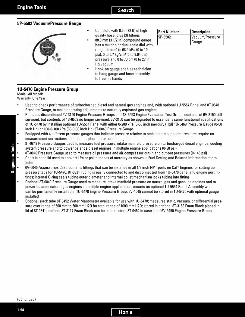
2581508
2581522
1-94
Dia
gnos
tic T
ools
Engine Tools
5P-6582 Vacuum/Pressure Gauge• Complete with 0.6 m (2 ft) of high
qualityhose,plus(3)fittings• 88.9 mm (3 1/2 in) compound gauge
has a multicolor dual scale dial with ranges from 0 to 68.9 kPa (0 to 10 psi), 0 to 0.7 kg/cm² (0 to 9.94 psi) pressure and 0 to 70 cm (0 to 28 in) Hg vacuum
• Hook-on gauge enables technician to hang gauge and hose assembly to free his hands
Part Number Description5P-6582 Vacuum/Pressure
Gauge
1U-5470 Engine Pressure GroupModel: All ModelsWarranty: One Year
• Used to check performance of turbocharged diesel and natural gas engines and, with optional 1U-5554 Panel and 8T-0840 Pressure Gauge, to make operating adjustments to naturally aspirated gas engines
• Replaces discontinued 6V-3150 Engine Pressure Groups and 4S-6553 Engine Evaluation Test Group; contents of 6V-3150 still serviced,butcontentsof4S-6553nolongerserviced;6V-3150canbeupgradedtoessentiallysamefunctionalspecificationsof 1U-5470 by installing optional 1U-5554 Panel with either 0-200 kPa [0-60 inch mercury (Hg)] 1U-5469 Pressure Gauge (0-60 inch Hg) or 100-0-100 kPa (30-0-30 inch Hg) 8T-0840 Pressure Gauge
• Equipped with 4 different pressure gauges that indicate pressure relative to ambient atmospheric pressure; require no measurement corrections due to atmospheric pressure changes
• 8T-0848 Pressure Gauges used to measure fuel pressure, intake manifold pressure on turbocharged diesel engines, cooling system pressure and to power balance diesel engines in multiple engine applications (0-58 psi)
• 8T-0846 Pressure Gauge used to measure oil pressure and air compressor cut-in and cut-out pressures (0-145 psi)• Chart in case lid used to convert kPa or psi to inches of mercury as shown in Fuel Setting and Related Information micro-
fiche• 6V-6045AccessoriesCasecontainsfittingsthatcanbeinstalledinall1/8inchNPTportsonCat® Engines for setting up
pressuretapsfor1U-5470;8T-0821Tubingiseasilyconnectedtoanddisconnectedfrom1U-5470panelandengineportfit-tings;internalO-ringsealstubingouterdiameterandinternalcolletmechanismlockstubingintofitting
• Optional 8T-0840 Pressure Gauge used to measure intake manifold pressure on natural gas and gasoline engines and to power balance natural gas engines in multiple engine applications; mounts on optional 1U-5554 Panel Assembly which can be permanently installed in 1U-5470 Engine Pressure Group; 6V-4045 cannot be stored in 1U-5470 with optional gauge installed
• Optional slack tube 8T-0452 Water Manometer available for use with 1U-5470; measures static, vacuum, or differential pres-sure over range of 500 mm to 500 mm H2O for total range of 1000 mm H2O; stored in optional 8T-3153 Foam Block placed in lid of 8T-0841; optional 8T-3117 Foam Block can be used to store 8T-0452 in case lid of 6V-9450 Engine Pressure Group
(Continued)

2581522
2742090
1-95
Diagnostic Tools
Engine Tools
1U-5470 Engine Pressure Group (Continued)Model: All ModelsWarranty: One Year
8T-0848 Pressure Gauge range 400 kPa (58 psi)8T-0846 Pressure Gauge range 1000 kPa (145 psi)1U-5469 Pressure Gauge range of engine boost or positive intake manifold pressure
0 - 200 kPa (0 - 60 inches Hg)
8T-0839 Differential Pressure Gauge range Up to 12 kPa [50 inches water (H2O)], as well as either 12 kPa (1.74 psi) pressure or vacuum
All other gauges in group read directly in kPa and psi8T-0840 Pressure Gauge range 0 - 100 kPa (0 - 30 inches Hg)Vacuum range 0 - -100 kPa (0 - -30 inches Hg)Operating temperature range -1° to 60° C (30° to 140° F) for differential pressure gauges. -18°
to 71° C (0° to 160° F) for all other gaugesGauge accuracy ±2 percent of full scale for differential pressure gauge. SAE
Grade A (±1.5 to 1 percent of full scale for all other gauges)Operating position Position has no effect on differential pressure gauge, if gauge
has been mechanically adjusted to ZERO in the test position (on all other gauges, position has no effect on accuracy)
Pressure media Differential pressure gauge — clean air and gases only (no liquids). All other gauges — air, gases and liquids (oil, water, antifreeze, fuel, etc.)
Size 390 x 310 x 190 mm (15.4 x 12.2 x 7.5 in)Weight 6.8 kg (15 lb)NOTE: DO NOT use any acids or other highly corrosive liquids in the gauges. Item DescriptionNot shown Form SEES5677 Conversion ChartNot shown Form NEEG2187 Title Decal
Part Number Description Use Used with102-6496 Adapter, 1/8 -27 NPTF to 1/8 -28
BSPTMAllows 1U-5470 Engine Pres-sure Group to be connected to the oil pressure switch port on the listed engines. Adapter requires the removal of the oil pressure switch on these en-gines in order for oil pressure readings to be taken.
C0.5, C0.7, C1.1, C1.5, C1.7, C2.2, C3.4
1U-5470 Engine Pressure Group (Continued)DO NOT use any acids or other highly corrosive liquids in the gauges.
Item Part Number Description-- 1U-5470 Engine Pressure Group
Parts List1 8T-0841 Case2 8T-0839 Differential Pressure Gauge3 8T-0846 Pressure Gauge4 1U-5469 Pressure Gauge5 8T-0848 Gauge GP - Pressure (3)6 4C-3974 Fitting - Union Bulkhead (8)7 8T-0821 Tubing, 16 m (52.5 ft)
(Continued)

2742090
2742672
2742691
2581568
1-96
Dia
gnos
tic T
ools
Engine Tools
1U-5470 Engine Pressure Group (Continued) (Continued)DO NOT use any acids or other highly corrosive liquids in the gauges.
Item Part Number DescriptionParts List (Continued)
8 4C-3973 Fitting - Connector (male) (6)9 4C-3972 Fitting - Male Elbow (Swivel) (6)10 4C-3971 Union (2)11 6V-6132 Cable Tie (4)12 6V-6045 Case - Plastic Form SEES5575 Accessories Label13 6V-6115 Packing Set Base
8T-0452
Optional 8T-0452 Water Manometer (SEHS8907, pg. 7)Item Part Number Description1 8T-0452 Water Manometer2 8T-3153 Foam Block
8T-0840
Optional 8T-0840 Pressure GaugeItem Part Number Description1 8T-0848 Gauge GP - Pressure (3)2 1U-5554 Panel Assembly
198-4240 Digital Pressure Indicator GroupModel: AllWarranty: Manufacturers One Year
• Used to measure vacuum, pressure, differential pressure, and temperature• Self-contained, microprocessor based digital meter• Uses sensors and cables to remotely measure systems under pressure• Indicator has four input connectors:
- Connector 1 measures pressure or vacuum - Connectors 1 and 2 measure differential pressure - Connectors 2, 3, and 4 measure pressure
• Includes Type-K thermocouple for measuring temperatureRepair InformationSPX Service Repair755 Eisenhower DriveOwatonna, MN 55060Attn: Repair DepartmentPhone: 800-344-4013
(Continued)

2581568
2742711
1-97
Diagnostic Tools
Engine Tools
198-4240 Digital Pressure Indicator Group (Continued)Model: AllWarranty: Manufacturers One Year
Visit the SPX Repair Track web link to complete and submit the form for proper authorization: https://repairtrack.spx.comOperating temperature 0° to 38° C (32° to 100° F)Storage temperature -40° to 66° C (-40° to 150° F)Battery 1U-9534 Alkaline Battery, 9 VoltBattery life (approx.) 1 transducer 108 hours, 2 transducers 77 hours, 3 transducers 51 hours, 4 transducers 43 hoursGroup weight 2.36 kg (5.2 lb)Carrying case 394 x 311 x 102 mm (15.5 x 12.3 x 4.0 in)Pressure pickup sensors 3,500, 35,000, 41,368 and 70,000 kPa (500, 5,000, 6,000 10,000 psi) (198-4240 Group does not include 5,000 psi pressure pickup)NOTE: The Digital Pressure Indicator Group pressure sensors cannot be used with Data View at the present time.
Part Number Description Range Accuracy/Specification198-4237 Pressure Pickup Sensor, 500 psi, blue con-
nector±0 - 30 inches Hg, ±0 - 100 psi, ±0- 500 psi, ±0 - 35 bar, ±0 - 3,500 kPa
0.5% ±0.33 inches Hg, 0.5% ±1 psi, 0.5% ±5 psi, 0.5% ±0.35 bar, 0.5% ±34 kPa
198-4238 Pressure Pickup Sensor, 5,000 psi, red con-nector
±0 - 5,000 psi, ±0 - 350 bar, ±0 - 35,000 kPa
0.5% ±50 psi, 0.5% ±3.5 bar, 0.5% ±340 kPa
198-4239 Pressure Pickup Sensor, 6,000 psi, orange connector
±0 - 6,000 psi, ±0 - 413 bar, ±0 - 41,368 kPa
0.5% ±60 psi, 0.5% ±4.1 bar, 0.5% ±413 kPa
251-9600 Pressure Pickup Sensor, 10,000 psi, orange connector
±0 - 10,000 psi, ±0 - 700 bar, ±0 - 70,000 kPa
0.5% ±100 psi, 0.5% ±7 bar, 0.5% ±700 kPa
8T-0458 K-Type Thermocouple Sensor -40° to 2500° F, -40° to 1350° C 0.5% ±2 of reading, 0.5% ±2 of reading
198-4240 Digital Pressure Indicator Group Parts• Used to measure vacuum, pressure, differential pressure, and temperature• Self-contained, microprocessor based digital meter• Uses sensors and cables to remotely measure systems under pressure• Indicator has four input connectors:• - Connector 1 measures pressure or vacuum• - Connectors 1 and 2 measure differential pressure• - Connectors 2, 3, and 4 measure pressure• Includes Type-K thermocouple for measuring temperatureNot Shown NEHS0818 Tool Operating Manual
(Continued)

2742711
2581616
2581634
1-98
Dia
gnos
tic T
ools
Engine Tools
198-4240 Digital Pressure Indicator Group Parts (Continued)
Item Part Number Description1 198-4234 Indicator (face decal NEEG2932)2 198-4236 Extension Cable, 20 ft (6 m) (2)3 198-4229 Cable - Digital Pressure Indicator 40 ft (12 m)4 198-4237 Pressure Pickup, 500 psi (3,500 kPa), blue connector4 198-4238 Pressure Pickup, 5,000 psi (35,000 kPa), red connector (optional)4 198-4239 Pressure Pickup, 6,000 psi (41,368 kPa), orange connector4 251-9600 Pressure Pickup, 10,000 psi (70,000 kPa), orange connector— 198-4240 Digital Pressure Indicator Group
Not shown— 198-4235 Foam Insert— 6V-3072 Case - Plastic (case decal NEEG2931)— 8T-0458 Wire - Thermocouple
Optional Items (Sold Separately)— 6V-0852 Cap - Dust— 6V-3965 Valved External Nipple, 9/16 in SAE— 6V-3966 Valved External Nipple, 1/4 in NPT— 6V-4144 Valved Replacement Coupler, 1/4 in NPT, internal thread— 8T-3613 Valved External Nipple, 1/8 in NPT
198-4229 Digital Pressure Indicator CableModel: AllWarranty: One Year
• Used to increase distance between pressure pickup and hand-held, digital pressure indicator
• Used with 198-4240 Digital Pressure Indicator (DPI)
• Allows technician greater freedom to move around during testing, especially when working on large equipment
• Overall length: 12 m (40 ft)ReferenceNEHS0818, Using the 198-4240 Digital Pressure Indicator Group
Part Number Description198-4229 Cable - DPI 40 ft
(12 m)
8T-5300 Timing Indicator GroupDiscontinued — Service/Repair Parts Available
ReferenceSEHS8580, Special Instruction
Item Part Number Description-- 8T-5300 Timing Indicator Group
Parts List1 6V-7145 Case2 8T-5250 Indicator (not serviced)3 8T-3253 Packing Set4 5P-7366 Cable Assembly - Power5 8K-4644 Fuse (5)
(Continued)

2581634
2581658
1-99
Diagnostic Tools
Engine Tools
8T-5300 Timing Indicator Group (Continued)Discontinued — Service/Repair Parts Available
Item Part Number DescriptionParts List (Continued)
6 6V-3093 Adapter - Transducer, 1/4 in NPTF7 6V-2199 Adapter - Transducer, 1/8 in NPTF8 6V-2197 Transducer - Magnetic TDC Pickup 114 mm (4.5 in)
long9 5P-7362 Cable Assembly - Signal TDC
Not Shown-- 6V-6045 Case - Plastic, NEEG2061 Accessories Case Decal
Additional accessories available separately-- 8T-5185 Transducer - Magnetic 17.8 cm (7.0 in) long-- 8T-5184 Transducer - Magnetic TDC Pickup 8.9 cm (3.5 in) long
310-4780 Diesel Injection DetectorModel: 3046, 3064, 3066 EnginesWarranty: Manufacturer’s
European Union compliant, CE marked• Used to detect fuel injection pulse on diesel engine fuel line• Used with 9U-5358 Digital Timing Light or other analyzer/tester with an inductive
pickup• Pickupclampfitsaroundfuellinefrominjectionpump• 6 mm diameter pickup clamp is included with 6.5 mm and 1/4 inch diameter
pickup clamps optional• Whenafuelinjectionpulseisdetecteditcausesindicatorlamptoflashand
sends a current pulse through inductive loop (cable) on unit• Inductive loop (cable) allows use of virtually any test equipment with an induc-
tive pickup• Faster and more accurate than drip timing an engineReferenceNEHS1012, Tool Operating Manual, 310-4780 Diesel Injection Detector for 3046, 3064, and 3066 EnginesOperating temperature -18 to 50° C (-4 to 122° F)Storage temperature -40 to 80° C (-40 to 176° F)Lead length 1.7 m (67 in)Power requirements 1U-9534 9 Volt BatteryDimensions (H x L x W) 120 x 60 x 25 mm (4.7 x 2.4 x 1.0 in)
Item Part Number Description1 310-4780 Diesel Injection Detector2 310-4777 Pickup Clamp, 6 mm diameter— 1U-9534 Battery - 9V Size (not shown)
Optional3 310-4776 Pickup Clamp, 1/4 in diameter4 310-4778 Pickup Clamp, 6.5 mm diameter

2581689
2581710
1-100
Dia
gnos
tic T
ools
Engine Tools
Magnetic TransducersModel: 3208Warranty: Six Months
8T-5184 Transducer• Has 89 mm (3.5 in) long steel shank which is 12.7 mm (0.5 in) shorter than existing 6V-2197 Transducer• Can be used in applications where 6V-2197 Transducer is too long, such as on some 3208 Engines where access to top
center hole in front cover is limited by fan belts and fan guard8T-5185 Transducer• Has 178 mm (7.0 in) long steel shank which is 63.5 mm (2.5 in) longer than 6V-2197 Transducer• Can be used in applications where 6V-2197 Transducer is too short, such as on D7G SA Tractor
Part Number Size8T-5184 88.9 mm (3.5 in) long8T-5185 17.8 cm (7.0 in) long
4C-6710 Governor Test Unit GroupModel: 3600 Family Engines with Heinzmann GovernorsWarranty: One Year
• Used to test and adjust Heinzmann Electronic Governors without running engine• Simplifiesinstallationandserviceofgovernor• Measures governor frequency when engine is running and feedback voltage
when engine is stopped• Simulates engine for following tests:
- Check governor frequency at different fuel levels - Adjust and check minimum and maximum governor frequency levels - Adjust speed droop during droop operation - Check effect of gain, stability and derivative value settings on operation of engine
ReferencesSEHS9222, Special InstructionSENR4661, Heinzmann Governor Service ManualFrequency range 100 - 10,000 Hz (± 5 Hz)Voltage range 1 - 6 Volts (± 50 mV)Simulator frequency 150 - 8,000 HzOutput voltage 8V peak-peak maximumCurrent consumption 8 mA maximumBattery 1U-9534 Battery, 9 VoltTemperature range 0° to 45° C (32° to 104° F)
Part Number Description4C-6710 Governor Test Unit Group

2581728
2581751
2581792
1-101
Diagnostic Tools
Engine Tools
8T-5301 Diesel Timing Adapter GroupModel: 300, 1100, 3200, 3300 and 3400 Series EnginesWarranty: One Year
• Used to check timing on diesel engines using discontinued 8T-5250 Timing Indicator
• Allows discontinued 8T-5250 Timing Indicator to measure engine/fuel system timing and mechanical advance
• Discontinued 6V-7910 Transducer installed in No. 1 fuel line to provide RPM signal to discontinued 8T-5250 Timing Indicator
• Groupincludesallitemsinfigure
Part Number Item Description8T-5301 -- Diesel Engine Timing Adapter Group
Parts List6V-2198 1 Extension Cable (X8)6V-7910 2 Transducer5P-7436 3 Adapter5P-7437 4 Adapter5P-7435 5 Adapter Group - Tee6V-3016 6 Washer
6V-9060 Spark Timing Adapter GroupModel: 3304, 3306, 3516Warranty: One Year
• Used to check timing on spark ignited engines using discontinued 8T-5250 Tim-ing Indicator
• Fiber optic link that allows discontinued 8T-5250 Indicator to check dynamic tim-ing on engines that have individual coils for each cylinder
• Connected to port labeled injection or spark transducer input; can also be used with discontinued 6V-3100 Timing Indicator Group and connected to port labeled Diesel Injection Transducer; transmitter portion of adapter is then connected to primary (low voltage) coil terminals of No. 1 cylinder on engine (NOTE: 6V-9060 Spark Timing Adapter Group will be destroyed if it is connected to the second-ary (high voltage) side of the coil.)
ReferenceSEHS8580, Special InstructionItem Description1 Transmitter, Discontinued
Item Part Number Description2 8T-5260 Cable, Discontinued3 8T-5257 Receiver, Discontinued4 8T-5258 Cable - Coil AdapterNot shown 1U-5524 Cable As. - Spark Timing Adapter— 6V-9060 Gas Engine Timing Adapter Group
1U-5524 Adapter Cable• Part of the 6V-9060 Spark Timing Adapter Group• Allows dynamic timing of engines equipped with integral shielded ignition coils and Altronic magnetos to be checked;
engines with Altronic magnetos have integral shielded ignition coils with 3-pin connectors for which 1U-5524 Adapter Cable is designed
(Continued)

2581792
3051851
2979429
2979445
1-102
Dia
gnos
tic T
ools
Engine Tools
1U-5524 Adapter Cable (Continued)• Connected at primary (low voltage) coil terminals of No. 1 cylinder; cable from magneto disconnected at primary coil
connector and two 1U-5524 Adapter Cable 3-pin connectors are coupled in between the coil and cable; remaining 2-pin connector of adapter is coupled to 6V-9060 Spark Timing Adapter Group; when 6V-9060 and TDC Magnetic Transducer are connected to discontinued 8T-5250 Indicator, engine RPM and timing displayed
373-4837 Temperature Sensor Breakout HarnessModel Usage: CT660 TruckWarranty: Manufacturer’s
• Used to measure voltage and resistance on circuits that go to the IAT sensor
Part Number Description373-4837 Temperature Sensor Breakout Harness
372-5251 Breakout HarnessModel Usage: CT660 Truck, CT11, CT13, CT15Warranty: Manufacturer’s
• Used to properly diagnose and service 11 & 13 L enginesSpecificationsDimensions 304.8 x 304.8 x 304.8 (12 x 12 x 12 in)Weight 2.95 kg (6.5 lb)
Part Number Description372-5251 Breakout Harness
372-5252 Breakout BoxModel Usage: CT660 Truck, CT11, CT13, CT15Warranty: Manufacturer’s
• A multi-cable device used to test electronic equipment• Usedwheresufficientspaceoraccesstoconnectionsarenoteasilyaccessible• Allows testing of the electronic control system components without disturbing
connectionsSpecificationsDimensions 381 x 304 x 76.2 mm (15 x 12 x 3 in)Weight 4 kg (8.8 lb)
Part Number Description372-5252 Breakout Box

2979594
2979219
1-103
Diagnostic Tools
Engine Tools
372-5274 Engine Harness Repair KitModel Usage: CT660 TruckWarranty: Manufacturer’s
• Kit allows system checks to be made on running engine for real time diagnostics as well as quality
• Includes 125 components• Contains all connectors and terminal pigtails to make computer-safe repairs on
engine electrical harnessServiceable PartsConnectors 398-1270, 398-1272, 398-1273, 398-1274,
398-1275, 398-1276, 398-1277, 398-1278, 398-1279, 398-1280, 398-1281, 398-1283, 398-1284, 398-1285, 398-1286, 398-1287, 398-1288, 398-1289, 398-1291, 398-1293, 398-1294, 398-1295, 398-1296
Clip-TPA 398-1271Tubes 398-1297, 398-1298, 398-1299, 398-1300,
398-1301, 398-1305, 398-1306, 398-1307, 398-1308, 398-1309, 398-1311, 398-1312, 398-1313, 398-1314, 398-1315
Terminals 398-1316, 398-1317, 398-1318, 398-1319, 398-1320, 398-1321, 398-1322, 398-1323, 398-1324
Backshells 398-1325, 398-1326, 398-1332, 398-1333Splice-Butts 398-1327, 398-1328, 398-1329Tube-Heat Shrink 398-1331
Part Number Description Dimensions Weight372-5274 Engine Harness Repair
Kit17 x 13 x 13 in 5 kg
373-4782 Coolant Mixer Valve Breakout HarnessModel Usage: CT660 TruckWarranty: Manufacturer’s
• Diagnostic harness used for engine coolant valve #1, (mixing valve)SpecificationsDimensions 152.4 x 101.6 x 6.4 mm (6 x 4 x 0.25 in)Weight 0.04 kg (0.08 lb)
Part No. Description373-4782 Coolant Mixer Valve Breakout Harness

2979239
2979532
1-104
Dia
gnos
tic T
ools
Engine Tools
373-4783 Coolant Flow Valve Breakout HarnessModel Usage: CT660 TruckWarranty: Manufacturer’s
• Diagnosticharnessusedforenginecoolantvalve#2,(flowvalve)SpecificationsDimensions 167.6 x 101.6 x 19.0 mm (606 x 4.0 x 0.75 in)Weight 0.04 kg (0.08 lb)
Part No. Description373-4783 Coolant Flow Valve Breakout Harness
372-5260 Breakout Tee KitModel Usage: CT660 TruckWarranty: Manufacturer’s
• Lead and probe test kit• Kit contains connectors necessary when testing in tight locations• Includes 2 tight spot test leads, over 40 spade and round terminal probes in 4 sizes, screw
banana plugs and breakout adaptersSpecificationsDimensions 279.4 x 190.5 x 44.45 mm (11 x 7.5 x 1.75 in)Weight .68 kg (1.5 lb)
Part Number Part Name Description372-5260 -- Breakout Tee Kit398-4980 Female Probe Small Gray Round Female .06
D (3 pack)398-4981 Male Probe Extra Large Green Male Round
.11 D (2 pack)398-4983 Female Probe Extra Large Green Female
Round .11 D (2 pack)398-4985 Male Probe Medium Yellow Male Spade
.12 (3 pack)398-4987 Female Probe Medium Yellow Female Spade
.12 (3 pack)398-4988 Male Probe Extra Small Blue Male Spade
.02 x .09 (3 pack)398-4989 Female Probe Small Blue Female Spade .02 x
.09 (3 pack)398-4990 Female Probe Medium Orange Female
Round .075 DIA (3 pack)398-5021 Male Probe Medium Orange Male Round
.075 DIA (3 pack)398-5052 Female Probe Small Purple Female Spade
1.5 x 8 mm (3 pack)398-5056 Male Probe Extra Small Purple Male
Spade 1.5 x 8 mm (3 pack)398-5057 Male Probe Large White Male Spade .25 x
.032 (2 pack)
Part Number Part Name Description398-5058 Female Probe Large White Female Spade .25
x .03 (2 pack)398-5059 Male Probe Small Gray Male Round .06
DIA T.P. (3 pack)398-5060 Male Probe Male Terminal Square .025
Black (3 pack)398-5061 Female Probe Female Terminal Square .025
Black (3 pack)398-5062 Female Probe Female, Delphi, Terminal
Spade .025 x .059 Red (3 pack)398-5063 Male Probe Male Terminal Spade .025 x
.039 Red (3 pack)398-5064 Male Probe Male Terminal Round 0.03
Blue (3 pack)398-5065 Female Probe Female Terminal Round 0.03
Blue (3 pack)398-5066 Male Probe Male Terminal Round 0.039
Green (3 pack)398-5067 Female Probe Female Terminal Round 0.039
Green (3 pack)398-5072 Tee Adapter Dual Banana Plug Tee Adapter
(each)398-5080 Test Lead Tight spot Black Test Lead
(each)
(Continued)

2979532
2979257
2979283
2979310
1-105
Diagnostic Tools
Engine Tools
372-5260 Breakout Tee Kit (Continued)Model Usage: CT660 TruckWarranty: Manufacturer’s
Part Number Part Name Description398-5081 Test Lead Tight spot Red Test Lead
(each)398-5082 Clip Screw on Alligator clip (1
each red and black)398-5083 Plug Screw on Banana plug (1
each red and black)
373-4784 EFP Breakout HarnessModel Usage: CT660 TruckWarranty: Manufacturer’s
• Diagnostic harness used for engine fuel low pressure sensorSpecificationsDimensions 167.6 x 101.6 x 19.0 mm (6.06 x 4.0 x 0.75
in)Weight 0.04 kg (0.08 lb)
Part No. Description373-4784 EFP Breakout Harness
373-4785 EOP Breakout HarnessModel Usage: CT660 TruckWarranty: Manufacturer’s
• Diagnostic harness used for engine oil pressure sensorSpecificationsDimensions 167.6 x 101.6 x 19.0 mm (6.06 x 4.0 x 0.75
in)Weight 0.04 kg (0.08 lb)
Part No. Description373-4785 EOP Breakout Harness
373-4786 MAT Breakout HarnessModel Usage: CT660 TruckWarranty: Manufacturer’s
• Diagnostic harness used for engine charge air, (manifold air) temp sensorSpecificationsDimensions 167.6 x 101.6 x 19.0 mm (6.06 x 4.0 x 0.75
in)Weight 0.04 kg (0.08 lb)
Part No. Description373-4786 MAT Breakout Harness

2979333
2979361
2979381
2979395
1-106
Dia
gnos
tic T
ools
Engine Tools
373-4787 Exhaust Lambda Sensor & V8 EGR Breakout HarnessModel Usage: CT660 TruckWarranty: Manufacturer’s
• Diagnostic harness used for exhaust Lambda sensor diagnosticsSpecificationsDimensions 279.4 x 40.6 x 25.4 mm (11.0 x 1.6 x 1.0 in)Weight 0.06 kg (0.14 lb)
Part No. Description373-4787 Exhaust Lambda Sensor & V8 EGR Breakout Harness
373-4788 After-treatment 2 Pin Breakout HarnessModel Usage: CT660 TruckWarranty: Manufacturer’s
• Diagnostic harness used for after-treatment temperature sensors and circuits• Additional diagnostics include fuel shutoff, fuel dump and doser circuit (for urea
injection)SpecificationsDimensions 271.8 x 20.3 x 25.4 mm (10.7 x 0.8 x 1.0 in)Weight 0.05 kg (0.11 lb)
Part No. Description373-4788 After-treatment 2 Pin Breakout Harness
373-4789 EGDP Breakout HarnessModel Usage: CT660 TruckWarranty: Manufacturer’s
• Diagnostic harness used for the exhaust gas delta pressure sensorSpecificationsDimensions 279.4 x 25.4 x 20.3 mm (11.0 x 1.0 x 0.8 in)Weight 0.04 kg (0.1 lb)
Part No. Description373-4789 EGDP Breakout Harness
373-4791 APS/IVS Breakout HarnessModel Usage: CT660 TruckWarranty: Manufacturer’s
• Diagnostic harness used on all throttle and sensor circuit diagnosticsSpecificationsDimensions 355.6 x 31.7 x 25.4 mm (14.0 x 1.2 x 1.0 in)Weight 0.07 kg (0.16 lb)
Part No. Description373-4791 APS/IVS Breakout Harness

2980130
2980143
2980171
2980183
1-107
Diagnostic Tools
Engine Tools
373-4744 Cold Weather Start Breakout HarnessModel Usage: CT660 TruckWarranty: Manufacturer’s
• Used to measure voltage and resistance on circuits connected to Cold Start Relay (CSR)
SpecificationsDimensions 203.2 x 177.8 x 50.8mm (8 x 7 x 2 in)Weight 0.3 kg (0.6 lb)
Part Number Description373-4744 Cold Weather Start Breakout Harness
373-4745 Big Bore Terminal Test Probe KitModel Usage: CT660 TruckWarranty: Manufacturer’s
• Used to access circuits in the connector harness and allows for use of Digital Multi-Meter without damaging the harness connectors
SpecificationsDimensions 111.8 x 210.8 x 43.2 mm (4.4 x 8.3 x 1.7 in)Weight 0.4 kg (0.9 lb)
Part Number Description373-4745 Big Bore Terminal Test Probe Kit
373-4747 EIM Power Relay Breakout HarnessModel Usage: CT660 TruckWarranty: Manufacturer’s
• Used to measure voltage and resistance on circuits to the EIM relaySpecificationsDimensions 254 x 203.2 x 25.4 mm (10 x 8 x 1 in)Weight 0.07 kg (0.15 lb)
Part Number Description373-4747 EIM Power Relay Breakout Harness
373-4749 ECT, EOT and EGR Control Breakout HarnessModel Usage: CT660 TruckWarranty: Manufacturer’s
• Diagnostic harness used for engine coolant temps 1 and 2, engine oil tempera-ture sensor and EGR control diagnostics.
Part Number Description373-4749 ECT, EOT and EGR Control Breakout Har-
ness

2980214
2980225
2980237
2980249
1-108
Dia
gnos
tic T
ools
Engine Tools
373-4750 CMP, CKP and FPCV Breakout HarnessModel Usage: CT660 TruckWarranty: Manufacturer’s
• Diagnostic harness used for the engine camshaft and crankshaft sensor diag-nostics and for high pressure fuel control module (MPROP).
Part Number Description373-4750 CMP, CKP and FPCV Breakout Harness
373-4751 FRP Breakout HarnessModel Usage: CT660 TruckWarranty: Manufacturer’s
• Diagnostic harness used for the engine high pressure fuel rail sensor
Part Number Description373-4751 FRP Breakout Harness
373-4752 MAP/IAT2 Breakout HarnessModel Usage: CT660 TruckWarranty: Manufacturer’s
• Diagnostic harness used for the engine boost pressure and temperature (MAP/IAT2) sensor
Part Number Description373-4752 MAP/IAT2 Breakout Harness
373-4754 BCS Breakout HarnessModel Usage: CT660 TruckWarranty: Manufacturer’s
• Diagnostic harness used for the engine boost pressure control actuator
Part Number Description373-4754 BCS Breakout Harness

2980261
2980273
2980285
2979134
1-109
Diagnostic Tools
Engine Tools
373-4778 EGR Position and Intake Throttle Control Breakout HarnessModel Usage: CT660 TruckWarranty: Manufacturer’s
• Diagnostic harness used for EGR position and intake throttle control circuit diagnostics
Part Number Description373-4778 EGR Position and Intake Throttle Control
Breakout Harness
373-4779 Retarder Control Breakout HarnessModel Usage: CT660 TruckWarranty: Manufacturer’s
• Diagnostic harness used for engine retarder valve control
Part Number Description373-4779 Retarder Control Breakout Harness
373-4780 Engine Fan Control Actuator Breakout HarnessModel Usage: CT660 TruckWarranty: Manufacturer’s
• Diagnostic harness used for engine electronic fan control
Part Number Description373-4780 Engine Fan Control Actuator Breakout
Harness
373-4781 After-treatment Fuel Pressure SensorModel Usage: CT660 TruckWarranty: Manufacturer’s
• Diagnostic harness used for engine after-treatment fuel pressure sensorSpecificationsDimensions 25.4 x 25.4 x 25.4 mm (1 x 1 x 1 in)Weight 0.06 kg (0.14 lb)
Part Number Description373-4781 After-treatment Fuel Pressure Sensor

2980358
2980397
2980410
2980474
1-110
Dia
gnos
tic T
ools
Engine Tools
373-4826 Cold Start Solenoid Test AdapterModel Usage: CT660 TruckWarranty: Manufacturer’s
• Used to properly diagnose the cold start solenoid
Part Number Description373-4826 Cold Start Solenoid Test Adapter
373-4841 500 OHM Resistor Jumper HarnessModel Usage: CT660 TruckWarranty: Manufacturer’s
• Used for operational diagnostics of sensor circuitsSpecificationsDimensions 127.0 x 19.0 x 19.0 mm (5.0 x 0.75 x 0.75 in)Weight 0.04 kg (0.1 lb)
Part Number Description373-4841 500 OHM Resistor Jumper Harness
373-4842 3 Banana Plug HarnessModel Usage: CT660 TruckWarranty: Manufacturer’s
• Used for operational diagnostics of sensor circuitsSpecificationsDimensions 149.9 x 129.5 x 10.2 mm (5.9 x 5.1 x 0.4 in)Weight 0.06 kg (0.12 lb)
Part Number Description373-4842 3 Banana Plug Harness
374-6405 CMP Breakout HarnessModel Usage: CT660 TruckWarranty: Manufacturer’s
• Diagnostic harness used for Cam position diagnostics on engineSpecificationsDimensions 157.5 x 94.0 x 17.8 mm (6.2 x 3.7 x 0.7 in)Weight 0.04 kg (0.08 lb)
Part Number Description374-6405 CMP Breakout Harness

2980487
2980500
2980513
1-111
Diagnostic Tools
Engine Tools
374-6406 MAT Breakout HarnessModel Usage: CT660 TruckWarranty: Manufacturer’s
• Diagnostic harness used on the intake manifold temperature sensor of engineSpecificationsDimensions 157.5 x 109.2 x 22.9 mm (6.2 x 4.3 x 0.9 in)Weight 0.04 kg (0.08 lb)
Part Number Description374-6406 MAT Breakout Harness
374-6407 WIF Breakout HarnessModel Usage: CT660 TruckWarranty: Manufacturer’s
• Two wire diagnostic breakout harness used on engineSpecificationsDimensions 320.0 x 20.3 x 20.3 mm (12.6 x 0.8 x 0.8 in)Weight 0.03 kg (0.07 lb)
Part Number Description374-6407 WIF Breakout Harness
374-6408 Air System Controller Breakout HarnessModel Usage: CT660 TruckWarranty: Manufacturer’s
• Ten wire diagnostic breakout harness used on engineSpecificationsDimensions 203.2 x 165.1 x 38.1 mm (8.0 x 6.5 x 1.5 in)Weight 0.1 kg (0.2 lb)
Part Number Description374-6408 Air System Controller Breakout Harness

2980526
2980538
2980572
1-112
Dia
gnos
tic T
ools
Engine Tools
374-6409 Compression Brake Breakout HarnessModel Usage: CT660 TruckWarranty: Manufacturer’s
• Four pin diagnostic breakout harness used on engineSpecificationsDimensions 152.4 x 114.3 x 25.4 mm (6.0 x 4.5 x 1.0 in)Weight 0.06 kg (0.1 lb)
Part Number Description374-6409 Compression Brake Breakout Harness
374-6410 ITR AND EGR Valve Breakout HarnessModel Usage: CT660 TruckWarranty: Manufacturer’s
• Diagnostic harness used on engine throttle valve (ETV) and exhaust gas recircu-lation (EGR)
SpecificationsDimensions 180.3 x 114.3 x 20.3 mm (7.1 x 4.5 x 0.8 in)Weight 0.08 kg (0.2 lb)
Part Number Description374-6410 ITR AND EGR Valve Breakout Harness
374-6411 AFS Breakout HarnessModel Usage: CT660 TruckWarranty: Manufacturer’s
• Diagnostic breakout harness used on engine fuel systemSpecificationsDimensions 165.1 x 109.2 x 17.8 mm (6.5 x 4.3 x 0.7 in)Weight 0.04 kg (0.08 lb)
Part Number Description374-6411 AFS Breakout Harness

2980584
2980597
2581777
1-113
Diagnostic Tools
Engine Tools
374-6412 AFT Downstream Fuel Pressure Breakout HarnessModel Usage: CT660 TruckWarranty: Manufacturer’s
• Diagnostic breakout harness used on engineSpecificationsDimensions 157.5 x 116.8 x 15.2 mm (6.2 x 4.6 x 0.6 in)Weight 0.05 kg (0.10 lb)
Part Number Description374-6412 AFT Downstream Fuel Pressure Breakout
Harness
374-6415 High Pressure Fuel System Breakout HarnessModel Usage: CT660 TruckWarranty: Manufacturer’s
• Diagnostic breakout harness used for performing diagnostics on high pressure fuel system
SpecificationsDimensions 381.0 x 304.8 x 19.0mm (15.0 x 12.0 x 0.7 in)Weight 0.10 kg (0.2 lb)
Part Number Description374-6415 High Pressure Fuel System Breakout
Harness
163-5443 Detonation Sensor HarnessModel: 3400, 3500, and 3600 Gas EnginesWarranty: One Year
• Used to determine condition of detonation sensor on 3400, 3500 and 3600 gas engines
ReferencePage 13, May 1999, Engine News, Testing Detonation Sensor for Proper Use
Part Number Description163-5443 Detonation Sensor Harness

2581812
2581832
2581853
1-114
Dia
gnos
tic T
ools
Engine Tools
Timing CablesModel: G3408C and G3412C Gas Engines (EIS, Electronic Ignition System)Warranty: One Year
• Used to check ignition timing using atiminglightandflywheelmarkings
• Used to determine if a primary sig-nal is going to each transformer
• Cable installs between ignition wiring harness and valve cover connector
• Makestiminglessdifficultbecauseignition wiring is encased in ridge/flexibleconduitorinabraidedwirebundle
Part Number Use143-4508 G3408C143-4509 G3412C
Block Heater Power CablesModel: D9R, D10R, D11R Track-Type TractorWarranty: Six Months
• Used to supply power to the block heater on large track-type tractor
• Length: 15.25 m (50 ft)• Provides watertight seal• Used with Marinco Engine Block
Heater connectors• Requires customer-supplied NEMA
standard locking receptacle 125 or 250 volt outlet for 30 amp electrical circuit
Part Number Description218-7221 125 VAC, 30 A218-7223 250 VAC, 30 A
FT1814 CableModel: All Models with Set PointsWarranty: None
• Used with set point indicator, with 6V-7091, 6V-7092, 6V-7093 and Fuel Injection Equipment Test Stands
• Fabricated by shortening 1P-7446 Cable to 180.3 cm (71 in)

2581866
2836751
2581884
1-115
Diagnostic Tools
Engine Tools
6V-3072 Carrying CaseDiscontinued 6V-4060 Indicator Group, Engine Set PointWarranty: One Year
• Depending on use, discontinued 6V-4060 Set Point Indicator can be stored with Engine Pressure Group or as individual unit in 6V-3072 Plastic Case
Items with No Part NumberItem Description2 Form SEHS7920 Label for 6V-3072 Case,
“6V-4060 Engine Set Point Indicator”5 Form SEHS8009 Label for 6V-6045 Acces-
sories Case
Item Part Number Description1 6V-3072 Case - Plastic, NEEG2574 Group Decal on
lid (9U-7402 Group)3 6V-4863 Foam Insert4 6V-6045 Case - Plastic, NEEG2061 Accessories
Case Decal
373-4609 Spark Test Group for DPF Spark Plug on Tier 4 EnginesModel Usage: All Tier 4 Engines that require a higher spark capable toolWarranty: Manufacturer’s
• In-linetoolusedtotestforsparkatdieselparticulatefilter(DPF)ignitersparkplugs
• Designed for use with higher current levels than 9U-6695 Electronic Spark Plug Firing Indicator
• Connect the tool in-line, between spark plug and plug wire when the engine is stopped,toolflashesamirrorimageofignitionsparkwhenengineisrunning
• For best access, tool is double-ended to offer a straight boot and 90° boot on one tool
• Spark plug wire adapter has straight spark plug boot on one end and insulator and test clip on other end [length: 27 cm (10.5 in)] for testing ignition coil
Part Number Description368-6232 Spark Tester370-6633 Spark Plug Wire Adapter373-4609 Spark Test Group
9U-6695 Electronic Spark Plug Firing IndicatorModel: Spark Ignited EnginesWarranty: One Year
• Greatly improved tool providing reliable way to diagnose ignition problems• Adjustablesensitivity—usercansetfiringindicatortoflashwhenplacednear
primary wire on exposed coils of 15.88 cm (6.25 in) bore engines• Flashing LED on top of indicator easily seen in daylight• Indicator can be carried easily in shirt pocket• Once user sets sensitivity, instrument is activated when spring clip is depressed• Rugged plastic housing and electronic circuit board combine durability features
for a dependable, durable instrumentDiameter 15.0 mm (0.57 in)Length 133.4 mm (5.25 in)Indicator bright red LEDBattery 3 required (147-6202 Battery)
(Continued)

2581884
2581904
2581926
1-116
Dia
gnos
tic T
ools
Engine Tools
9U-6695 Electronic Spark Plug Firing Indicator (Continued)Model: Spark Ignited EnginesWarranty: One Year
Part Number Description9U-6695 Electronic Spark Plug Firing Indicator
9U-5358 Digital Timing LightModel: All spark ignited enginesWarranty: Manufacturer’s Three Year
• Replaces canceled 5P-6584 Timing Light• Inductive clamp provides fast and easy hookups• SuperbrightXenonflashtubeforeasierreadingoftimingmarks• Built with dependable, solid-state circuitry for years of trouble-free service• Detachable lead set• Works on all 12 volt systems• 2 or 4 cycle operation• Light-weight and easy to handle (1.1 kg [2.4 lb])Repair InformationSPX Service Repair755 Eisenhower DriveOwatonna, MN 55060Attn: Repair DepartmentPhone: 800-344-4013Visit the SPX Repair Track web link to complete and submit the form for proper authorization: https://repairtrack.spx.com
Part Number Description9U-5358 Digital Timing Light
8T-5100 Smoke Meter GroupDiscontinued — Service/Repair Parts Available
ReferenceSEHS8731, Special Instruction
Item Part Number Description1 6V-9449 Case, SEES5696 Decal (8T-5100 Group) Block Group (foam
insert with case)2 8T-5309 Pump Group3 8T-5307 Evaluator4 8T-5310 Clamp Assembly5 8T-5311 Mounting Group6 8T-5304 Probe7 8T-5305 Probe8 8T-5323 Filter Paper-- 8T-5100 Smoke Meter Group

2581938
1-117
Diagnostic Tools
Engine Tools
9U-6958 Magneto Peak Detect ModuleModel: 3500 and 3600 EnginesWarranty: One Year with the Dealer Service Tools Division Tool Repair Service
• Used to check magneto performance during actual operating conditions (prob-lem could be spark plug or magneto related)
• When used with 257-9140 Digital Multimeter or an equivalent, serviceman can measure magneto output DC Voltage
• Provides interface to magneto ignition system (9U-6959 T-Cable is included with the 9U-6958)
• Providesaseparatevoltageoutputforoscilloscopeviewingoffiringpulsetrain• Does not require power to operate• AllitemsinfigureareincludedReferenceNEHS0588, Tool Operating ManualInput 0 - 200 VDCDC voltmeter connections 0 - 200 VDCScope connections 0 - 200 VDCOperating temperature -40° to 60° C (-40° to 140° F)Dimensions 168 x 190 x 41 mm (6.6 x 7.5 x 1.6 in)Weight 0.5 kg (1 lb)
Part Number Description9U-6958 Magneto Peak Detect Module

2581961
2743097
2581985
1-118
Dia
gnos
tic T
ools
Flow Tools
Flow Tools
8T-2700 Blowby/Air Flow Indicator GroupDiscontinued—Service/Repair Parts Available
Item Part Number Description— 8T-2700 Blowby/Air Flow Indicator Group1 6V-7145 Case2 8T-2685 Pickup - Blowby (1,000 CFH)
Service/Repair Parts— 8T-0899 Membrane Switch— 8T-0844 Front Cover— 8T-0887 Connector Assembly— 8T-1005 Liquid Crystal Display
Optional items that can be ordered to use with the blowby/air flow instrument
Item Part Number Description Use1 5P-7366 Cable Assembly
- PowerConnects machine batteries (11 - 40 VDC) to hand-held indicator
2 8T-5268 Converter - 11V DC 300mA
Converts 110/220 VAC, 50/60 Hz, power supply to 11 top 20 VDC at 0.3 A maximum for powering indicator
3 6V-2198 Extension Cable (X8)
Operates indicator more than 914.4 mm (3 ft) from the pickup
1U-8860 Large Engine Blowby Pickup GroupModel: 3500, 3600 Family Engines, Larger 300 Family EnginesWarranty: One Year
• Replaces 8T-2685 Small Pickup for measurement of 3500 Engine blowby; use 8T-2685 small pickup on these engines for short duration test only because of reduction of engine breather tube during test
• Large 38 mm (1.5 in) ID pickup used on large engines without increasing crankcase pressure• Checks blowby volume on Cat® 3500 and 3600 Engines and larger 300 Series Engines, as well as competitive large engines• All-metal construction and large size makes tool suitable for permanent installation on engines; permanent installation al-
lows continuous monitoring of blowby, making group useful for dynamometer rooms, marine or generator set applications• Canalsomeasureairvelocitysuchasradiatorcoolingairflow• Largeblowbymeterhasnomovingpartsbecauseanultrasonicsoundvortexsheddingprinciplemeasurestheairflow
(makes the pickup reliable and virtually maintenance free)• Pickup meter is sensitive to high frequency engine noise; to avoid incorrect readouts, keep pickup as far from engine as
possible when making blowby measurements; do not put pickup near turbocharger or fan blades because this can cause reading error
ReferencesSEHS8984, Special Instruction, Large Engine Blowby Pickup Group
(Continued)

2581985
2743194
2582015
1-119
Diagnostic Tools
Flow Tools
1U-8860 Large Engine Blowby Pickup Group (Continued)Model: 3500, 3600 Family Engines, Larger 300 Family EnginesWarranty: One Year
1U-8860 GroupCase size (W x D x H) 432 x 330 x 114 mm (17 x 13 x 4.5 in)Weight of 1U-8860 Group 6.1 kg (13.5 lb)Weight of discontinued 1U-8861 Pickup only 3.0 kg (6.5 lb) Item Description2 SEHS8984 Special Instruction3 Large Engine Pickup (not serviced)
Item Part Number Description1 6V-7145 Case4 9M-0164 Clamps - Nose5 1U-8863 Conversion Group6 1U-8868 Pickup Hose-- 1U-8860 Large Engine Blowby/Air Flow Pickup Group (For 3500
and 3600 Engines)
Optional Items
Optional items for use with large engine pickup group (Items 3, 4, and 5 are also optional items for use with discontinued 8T-2700 Indicator Group for small engines,
and may already be in your shop.)Item Part Number Description1 8T-5297 Extension Cable 0.9 m (3.0
ft)2 6V-2198 Extension Cable (X8)3 5P-7366 Cable Assembly - Power4 8T-5268 Converter - 11V DC 300mA
154-8100 Medium Engine Fuel Flowmeter GroupDiscontinued—Service/Repair Parts AvailableRepair InformationCheck Calibration and RepairsATS8201 N. University StreetPeoria, IL 61615Attn: Caterpillar® Diagnostic Tool Repair
(Continued)

2582015
2582030
1-120
Dia
gnos
tic T
ools
Flow Tools
154-8100 Medium Engine Fuel Flowmeter Group (Continued)Discontinued—Service/Repair Parts AvailablePhone: 800-328-7287 309-693-4170 (Outside North America)Email: [email protected] Calibration and RepairsFlow Technology8930 South Beck Avenue, Suite 107Tempe, AZ 85284Phone: 480-240-3400Fax: 480-240-3401Email: [email protected] site: ftimeters.comReferencesNEHS0697, Tool Operating ManualNEHS0698, Tool Operating Manual
Part Number Description154-8100 Medium Engine Fuel Flowmeter Group
168-7740 Fuel Flowmeter Group, 3600 EngineDiscontinued—Service/Repair Parts Available
Item DescriptionNot shown NEHSO74O Tool Operating
ManualNot shown NIST Traceable Flowmeter
CalibrationCertificates5 NEEG2839 Decal
Item Part No. Description1 168-7739 Sight Glass2 154-8107 Junction Box3 8T-9280 Power Supply4 5P-7366 Cable Assembly - Power5 4C-9660 Carry Case5 168-7742 Component Foam Insert5 154-8099 Lid Foam Insert6 154-8106 Display - Hand Held7 154-8097 Cable, 6.1 m (20 ft) (8T-9280 to 154-8107)8 154-8095 Cable— 168-7740 System Group - Fuel
Item Part No. DescriptionOptional Items (Sold Separately)
— 154-8096 AC Power Supply Group— 133-6975 Cable - Power— 137-0171 Adapter - Plug AC— 131-5047 Cable - Power, 110 VAC (USA Plug)
Optional Items for discontinued 168-7730 and discontinued 168-7740
— 168-7755 Cable— 168-7750 Hose/Adapter Group— 168-7733 Hose Assembly, size 20, 1 m (3 ft)— 5P-2712 Thermo-Hydrometer, Assembly API Gravity
Scale— 1P-7438 Beaker— 1P-7408 Thermo-Hydrometer, Gravity Scale— 154-8093 Extension Cable, 6.1 m (20 ft), (154-8107 to
154-8095)

2743432
2582070
2743693
1-121
Diagnostic Tools
Flow Tools
168-7740 Fuel Flowmeter Group, 3600 Engine (Continued)Additional Items Necessary for Testing 3612 and 3616 EnginesRepair InformationThe 168-7730 and 168-7740 Fuel Flow Meters should have the calibration checked annually.ATS (Advanced Technology Service) can provide this service. If recalibration is required,thefuelflowmetersshouldbereturnedtoFlowDynamicsorTrigasFI,thesuppliers.Recalibrationisrequirediftheflowmeterhasbeenphysicallydamaged.Improperstorageandcontaminationinthefuelcanleadtophysicaldamagetotheflowmeter.Items with No Part NumberItem Description Qty3 NEEG2180 Decal 2
Item 4 Part Number Description Qty.1 1U-5295 Accumulator 22 168-7736 Swivel Tee 2Not shown 3K-0360 Seal - O-ring - STOR (SAE 3/4 - 16) 6Not shown 5P-2963 Charging Adapter —
Small to Medium Engine Burn Rate Meter Systems with Hand Held Display or No DisplayModel: 3116, 3126, 3176, 3208, 3304, 3406, and 3408 EnginesWarranty: One Year
• Used to evaluate engine performance• Provides extremely accurate (±1% of reading) measurement of burn rateBurn Rate Meter• Uses a positive-displacement, rotary piston burn rate meter to measure burn
rate and a built-in heat exchanger to cool return fuel• Airbubblesinreturnflowdonotaffectburnratereadings
Burn Rate Computer• 179-0701 Burn Rate Computer provides automatic temperature compensation
and output scaling• Burn rate computers microprocessor linearizes output signal and temperature
to provide burn rate measurement accurate to ±1% of actual valueOutput Signals• Includes frequency output signal to allow 131-5050 Dataview or 9U-7401 Multit-
ach II to display burn rate• Provides RS485 Communications for 154-8106 Fuel Flow Hand-Held Display• 154-8106Displayflashes“UNDERFLOW”or“OVERFLOW”whenfuelflowisout
of the allowable rangePower Supply• Uses 11-32 volt DC engine battery with an optional 100-240 VAC power supply
available• The power switch on 179-0701 Burn Rate Computer must be in “OFF” position
when connecting an AC power supply or the system will not power up• Not recommended for engines with supply fuel lines larger than a #10 JIC be-
causeoffuelflowrestriction
(Continued)

2743693
2743759
1-122
Dia
gnos
tic T
ools
Flow Tools
Burn Rate Computer (Continued)
NOTICEDo not use the Burn Rate Meter System for 3500 Engines. Restriction created byburn rate meter will cause return fuel to overheat, resulting in engine damage. NOTICEThe meter should be upright, with the carrying handle on top when beingoperated. The meter can be tipped 30 degrees from an upright position and stillwork properly.
Details
Burn Rate MeterBurn rate 4 - 260 Lph (1.1 - 69.0 gph)Accuracy ± 1% of reading, ± 0.4 Lph (0.10 gph)Frequency output scaling 10 Hz = 1 gphFuel TemperatureFuel temperature range -17.7° to 85° C (0° to 185° F)Fuel temperature accuracy 0.5°C(1°F)providingfuelhasbeenflowingthroughburnrate
meter long enough to stabilize the readingPower SupplyDC 11 - 32 VDC at 10 A maximumHorsepower RangeHorsepower 11.3 Kw (15.2 Hp) — 735 Kw (1000 Hp)Optional Alternating Current179-0713 AC Power Supply 100 - 240 VAC, 47 - 63 Hz at 1.6 A input provides 24 VDC, 3.0 A
outputLow Filter Response TimesFlow change from 11.4 Lph (3 gph) to 121.3 Lph (32 gph) 6 secondsFlow change from 121.3 Lph (32 gph) to 11.4 Lph (3 gph) 21 secondsHigh Filter Response TimesFlow change from 11.4 Lph (3 gph) to 121.3 Lph (32 gph) 4 secondsFlow change from 121.3 Lph (32 gph) to 11.4 Lph (3 gph) 6 secondsWeight and Overall Size179-0700 17.7 kg (39 lb) — 320 x 298 x 130 mm (12.6 x 11.8 x 5.1 in) in-
cludesfilter179-0701 3.2 kg (7 lb) — 260 x 160 x 90 mm (10.3 x 6.3 x 3.5 in)179-0705 9.5 kg (21 lb) — 660 x 394 x 109 mm (26.0 x 15.5 x 4.3 in)

2743939
2744065
2582134
1-123
Diagnostic Tools
Flow Tools
179-0710 Small to Medium Engine Burn Rate Meter System with Handheld Display
Item Part Number Description1 179-0700 Burn Rate Meter2 179-0701 Burn Rate Computer3 179-0702 Cable4 179-0705 Hose Group5 4C-9660 Carry Case6 179-0706 Foam Insert7 154-8106 Display - Hand Held8 154-8095 Cable9 5P-7366 Cable Assembly - Power10 6V-2198 Extension Cable (X8)-- 179-0710 Engine Burn Rate Meter System
Repair InformationRepair InformationThe 179-0710 Burn Rate Group should have the calibration checked annually. ATS (Advanced Technology Service) can provide this service. ATS can also provide recalibration or re-pairifrequired.Recalibrationisrequirediftheflowmeterhasbeen physically damaged. Improper storage and contamination inthefuelcanleadtophysicaldamagetotheflowmeter.ReferenceNEHS0776, Using the Caterpillar 179-0710 Burn Rate Fuel Flow Measurement System
Service/Repair Parts (Sold Separately)Item Part No. Description1 179-0703 Metric to JIC Adapter2 179-0704 Electronic Connector (Fuel Meter)3 179-0708 Temperature Sensor4 081-4662 Fuel Filter
Optional Parts-- 131-5047 Cable - Power, 110 VAC (USA Plug)-- 133-6975 Cable - Power-- 137-0171 Adapter - Plug AC
Service/Repair Parts (Sold Separately)Item Part No. Description
Optional Parts (Continued)-- 154-8093 Extension Cable, 6.1 m (20 ft), (154-8107 to
154-8095)-- 5P-2712 Thermo-Hydrometer, Assembly API Gravity
Scale-- 179-0715 Cable Assembly - (Twin Engine)-- 1P-7408 Thermo-Hydrometer, Gravity Scale-- 1P-7438 Beaker-- 179-0713 Power Supply
FT2320 De-Aerator GroupFT2309 De-Aerator TankModel: Engines with PT-Type Fuel System (mainly Cummins Engines)Warranty: None
• Removesairinreturnfuelflowfromdieselengine;removalofairrequiredwhenusingCaterpillar® Fuel Flow Monitor Sys-tem
• Needed on engines with PT Type fuel system, used mainly by Cummins Engine Company; other engines may also have air in return fuel and require use of this group
• De-aerator system measures burn rates on competitive engines with Caterpillar® Fuel Flow Monitor System
(Continued)

2582134
1-124
Dia
gnos
tic T
ools
Flow Tools
FT2320 De-Aerator Group (Continued)FT2309 De-Aerator TankModel: Engines with PT-Type Fuel System (mainly Cummins Engines)Warranty: None
• Tank designed to slow velocity and reverse direction of fuel so any air tends to separate from fuel and rise to top of tank; inletandoutletextendedinsidetanksoflowchangesdirectiontoaidseparation;bafflesintankreducepossibilityofanyairtrappedattopoftankfrombeingrecombinedwithfuelwhenvehiclemovesoverroughground;severalfloatventsacrosstop of tank allow air to pass but close to liquids
ReferenceSEHS8874, Special Instruction, Operating Caterpillar Fuel Flow Monitor SystemFuel/Air Separator TankTheFuel/AirSeparatortankisusedtoremoveanyairinthereturnfuelflowfromadieselengine.Thistankisneededonenginesusing the PT type fuel system, used mainly by Cummins Engine Co. Some other engines may also have air in the return fuel and require the use of this tank or some other method to remove the air. The removal of the air is required so that the fuel lines do not become full of air when using the one meter method of fuel measuring and is more critical when using the two meter method of measuring fuel.The design of the tank is such that the velocity of the fuel is slowed and its direction is reversed so that any air will tend to sepa-ratefromthefuelandrisetothetopofthetank.Theinletandoutletareextendedinsidethetanksothattheflowmustchangedirectionasanaidtotheseparationoftheairfromthefuel.Therafflesinthetankaretoreducethepossibilityofanyairthatmight be trapped near the top of the tank from being recombined with the fuel if the tank is tilted or agitated by a vehicle moving overroughground.Theholesinthebafflesaidinthescrubbingoftheairfromthefuel.Across the top of the tank are several Maid-O-Mist vents that allow air to pass but will close to liquids. These vents however will permit air to enter if a negative pressure exists in the tank. Therefore a small positive pressure must be maintained within the tank. (With a Cummins engine this positive pressure must be kept as low as possible to prevent it affecting the fuel system.)TheMaid-O-Mistventscontainafloattheshutsofftheoutletsothatliquidswillnotbereleasedtotheatmosphere.Howeverifthevehicleencountersaseverebumporroughgroundthesefloatsmayallowasmallamountofliquidtoescape.Thede-aeratortankislocatedabovethefueltanktopreventfuelfromsiphoningoutofthefueltankandfillingthede-aeratortank. The de-aerator tank is mounted perpendicular with the vehicles frame, to reduce the possibility of fuel being mixed with air when the vehicle moves over rough ground.Boost PumpOn Cummins engines using the PT type fuel system it is possible to get zero return fuel at low idle. The large Caterpillar®fuelflowmonitorsystemmusthaveaminimumof40gallonsperhouroffuelflowtooperate.Ifthefuelflowfallsbelow40gallonsperhourthefuelmonitorwillnotreadfuelburn,butwillflashanerrormessage.Theboostpumpcirculatesenoughfuelthroughthesupplyandreturnfuelflowmeterstokeepthemintheiroperatingrange.Since the boost pump circulates the same amount of fuel through the supply and return meters, the burn rate created by the boost pump is zero. (Burn rate-supply rate-return rate).Item Part Number Description1 FT2309 De-Aerator Tank2 — Vent6 — Hose8 — Reducer9 — Hose
(Continued)

2582134
2837315
1-125
Diagnostic Tools
Flow Tools
FT2320 De-Aerator Group (Continued)FT2309 De-Aerator TankModel: Engines with PT-Type Fuel System (mainly Cummins Engines)Warranty: None
Item Part Number Description3 5P-6213 Plug4 009-4440 Connector5 067-6684 Reducer7 5P-2242 Swivel Tee10 061-9463 Pump Fitting11 5P-6520 Boost Pump12 1U-5303 Flowmeter Group13 1U-5304 Flowmeter Group14 8T-0821 Tubing15 4C-3972 Fitting16 3B-6768 Adapter - STR (NPTF)
Heat Exchanger Pressure Test ToolingModel Usage: 3516C Marine EngineWarranty: Six Months
• Used to pressure test 300-5622 Heat Exchanger• Usedwithfourbolts,O-ring,and1/4inchNPTfitting• Made from stainless steel to eliminate corrosionReferenceKENR6055 3500C Marine Engines Disassembly and Assembly
(Continued)

2837315
1-126
Dia
gnos
tic T
ools
Flow Tools
Heat Exchanger Pressure Test Tooling (Continued)Model Usage: 3516C Marine EngineWarranty: Six Months
366-3468 CoverOverall size 69.3 mm (2.73 in) squareThickness 6.35 mm (.25 in)Weight 0.9 kg (2 lb)366-3469 Mounting BarDiameter 50 mm (1.97 in)Length 371.8 mm (14.64 in)Weight 5.6 kg (12.3 lb)
Part Number Description366-3468 Cover366-3469 Mounting Bar

2582163
3037095
1-127
Diagnostic Tools
Measuring Tools
Measuring Tools
8T-1000 Electronic Position Indicator GroupDiscontinued — Service Parts AvailableReferenceSEHS8623, Special Instruction
Item Part Number Description1 6V-3072 Case - Plastic, NEEG2574
Group Decal on lid (9U-7402 Group)
2 6V-6045 Case - Plastic, NEEG2061 Accessories Case Decal
3 8T-5295 Foam Insert4 6V-2198 Extension Cable (X8)5 8T-1002 Position Probe (X4)-- 8T-1000 Indicator GP - POS
391-8170 Emission Analyzer with Bluetooth393-0673 Emission Analyzer without BluetoothWarranty: Manufacturer’s
European Union Compliant, CE marked• Used for compliance testing and troubleshooting the combustion process• Measurescombustionefficiencyandmonitorsemissions• Providesamultitudeoffieldconfigurationsforeasiersetupandperformance• Offers exclusive sensor design, patented gas paths, active sample conditioning and advance data logging and reporting• Equipped to handle low thresholds and still deliver high accuracy• Emission Analyzer can also be used for boiler and burner testing and industrial processes testingEmission Analyzer OverviewThe 391-8170 and 393-0673 Emission Analyzers provide the following:• Sample Gas Conditioning• Fresh Air Valve• Dilution System• Data BUS capability with re-catalyst and post catalyst testing screens• Differential pressure sensor• Type K or S temperature probe input• Rechargeable battery• Integrated combustion air sensor• Trigger input• Data memory• DC Power Input (11-40VDC), DC Power Cable with battery clips optional 393-0675• Carrying strap• Bluetooth module upgrade which enables communication between the handheld controller to the analyzer box and also for
the analyzer box to the computer. Some countries may have Bluetooth licensing issues. For those countries, the 393-0673 should be used.
• Power cord (shipped to match the country)• 6 foot data connection cable• IR printer• Thermal printer paper – 6 rolls (10 year legibility)• Particlefilters–packof30(20tubularfiltersforanalyzerand10flatanalyzergasprepfilters)• Pelican (or equal) Transport Case with wheels• Calibrationcertificate(typeofcertificatecountryspecific)• Easy Emission software with USB cord (mini USB to standard USB)
(Continued)

3037095
3037136
1-128
Dia
gnos
tic T
ools
Measuring Tools
391-8170 Emission Analyzer with Bluetooth (Continued)393-0673 Emission Analyzer without BluetoothWarranty: Manufacturer’s
Measurement Range and AccuracyO² Oxygen sensor (0-21%) 0.1 resolution: System accuracy +/- 0.8% of full scale valueCO module (0-10,000 ppm, 1 ppm resolution, H² compensated): System accuracy +/- 5% of reading (200 – 2000 ppm); +/- 10% (2001 to 10,000 ppm)NO module (0-3,000 ppm, 1 ppm resolution): System accuracy +/- 5% of reading (200 – 2000 ppm); +/- 10% (2001 to 4,000 ppm)NO² module (0 – 500 ppm, 0.1 ppm resolution): System accuracy +/- 5% of reading (100 – 500 ppm); +/- 5 ppm (0 – 99.9 ppm)Gasengineprobe13”,2000°F,7footTeflon-linedhose(8mmdiameter)Dieselengineprobe13”,2000°F,sinteredfilter,7footTeflon-linedhose(14mmdiameter)
Control Unit Technical Data
Control Unit Technical DataOperating Temperature 20° F to 115° FStorage Temperature -4° F to 122° FBattery Type Li-ionBattery Life 5 Hours (without wireless connection)Memory 2MB (250,000 measurement value)Weight 0.97 lbsDimensions 10 x 4.5 x 2.3 inProtection Class IP 40

3037144
3037155
3037163
1-129
Diagnostic Tools
Measuring Tools
Specifications
SpecificationsDimensions 330.2 x 127 x 436.9 mm (13 x 5 x 17.2 in)Weight 4.79 kg (10.58 lbs)Storage Temperature -20° to 50°C (-4° to 122°F)Operating Temperature -5.5° to 45°C (22° to 113° F)Housing Material ABSMemory 250,000 Measurement ValuesAC Power Supply 90 to 260 V (47 to 65 Hz)DC Voltage Supply 11 to 40 VMaximum Dust Load 20g/m³dustinfluegasDewpoint Calculation 0° to 100°C (32 to 212°F)Maximum Positive Pressure Flue Gas 20 “H2OMaximum Negative Pressure -120 “H2OPump Flow Rate 1l/min.withflowratemonitoringHose Length Maximum 53 ft (corresp. to 5 probe hose extensions)Maximum Humidity Load +158°F at gas input of analyzer boxTrigger Input Voltage 5to12Volt(risingorfallingflank) Impulse Width >1 sec Load: 5 V/maximum. 5 mA, 12 V/maximum, 40 mAProtection Class IP40Battery Life Maximum Load Approx. 2.5 h
Serviceable Parts
Serviceable Parts391-8171 Engine Probe Thermocouple Upgrade391-8175 Easy Emission Software with USB Cord391-8176 O² Replacement Sensor391-8177 CO Replacement Sensor391-8178 NO Replacement Sensor391-8179 NO² Replacement Sensor391-8180 Replacement Filter for NO Sensor391-8181 Particle Filter393-0675 DC Power Cable with Battery Clamps393-0676 Battery for Base Unit393-0677 Gas Engine Probe 8 mm393-0678 Diesel Engine Probe 14 mm393-0679 6 Foot Data Cable393-0681 Thermal Paper 6 RollNote: Additional options are available from the manufacturer
Countries Licensed for Bluetooth:Europe including all EU member states
Austria, Belgium, Bulgaria, Cyprus, Czech Republic, Denmark, Estonia, Finland, France, Germany, Great Britain, Greece, Hungary, Ireland, Italy, Latvia, Lithuania, Luxembourg, Malta, Netherlands, Poland, Portugal, Romania, Slovakia, Slovenia, Spain, Sweden and TurkeyEuropean countries (EFTA)Iceland, Liechtenstein, Norway and SwitzerlandNon-European countriesCanada, USA, Japan, Ukraine, Australia, Colombia, El Salvador, Venezuela
(Continued)

3037163
2582178
2582200
1-130
Dia
gnos
tic T
ools
Measuring Tools
Countries Licensed for Bluetooth: (Continued)Europe including all EU member states
Contact Information USA and International:http://www.testo350.com/contact.html
4C-8753 Extended ColletModel: 3500 Family EnginesWarranty: Six Months (Not repairable)
• Improves accuracy of fuel setting measurement and adjustment on the 3500 Engine
• Used with 8T-1002 Electronic Position Indicator Probe or dial indicator• Prevents side loading of probe shaft by fuel stop lever in governor; side loading
can cause setting errors and breakage of contact point on indicator• Attaches to indicator probe or dial indicator; is correct length for 5P-7263 Con-
tactPointspecifiedin3500fueltestingandadjustinginstructions• Has been added to 6V-7880 Timing and Fuel Setting Tool Group• Fits all dial indicators with 9.5 mm (0.375 in) mounting boss• 82.6 mm long; 3/8-16 thread for mounting on engine• Allows 25.4 mm (1.0 in) probe travel when used with 76.2 mm (3 in) shaft exten-
sionReferenceSEHS9278, Special Instruction
Part Number Description4C-8753 Extended Collet
8T-5096 Dial Indicator Test GroupWarranty: Six Months
• Provides tooling used in taking many different service measurements such as gear backlash, end clearance, side clearance, valve movement or rack position
• Contains all components of the 7H-1949 Dial Indicator Group, along with an 8S-2329 Base and 8S-2327 Post
• Magnetic base provides easier and quicker mounting of the dial indicator; the former 7H-1949 Dial Indicator Test Group can be updated by adding the 8S-2329 Base and the 8S-2327 Post
Item Part Number Description1 2P-8311 Block1 6V-3072 Case - Plastic, NEEG2574 Group Decal on
lid (9U-7402 Group)2 7H-1946 Arm3 7H-1941 Base4 7H-1942 Indicator5 8S-2329 Base6 7H-1940 Universal Attachment7 7H-1947 Holder8 8S-2327 Post9 7H-1945 Holding Rod
(Continued)

2582200
2582226
1-131
Diagnostic Tools
Measuring Tools
8T-5096 Dial Indicator Test Group (Continued)Warranty: Six Months
Item Part Number Description10 7H-1645 Holding Rod11 7H-1944 Post12 7H-1943 Clamp13 7H-1948 Snug-- 8T-5096 Dial Indicator Test
6V-7926 Dial Indicator GroupWarranty: Six Months
• Used primarily for measuring off-engine timing dimensions when setting fuel pump lifters
• Measurements made with a 25.4 mm (1.0 in) travel indicator and 5 contact points• Can also be used in other applications for accurate depth measurements up to
127 mm (5 in)
Item Part Number Description1 6V-3073 Case - Plastic1 6V-7029 Block - Top1 6V-7924 Holder Block2 8S-3158 Indicator3 3P-1565 Collet Clamp4 5P-4156 Base5 5P-4163 Point - Indicator Contact,
120.65 mm (4.75 in) long6 5P-4162 Contact Point (X4)7 5P-4161 Point - Indicator Contact,
69.85 mm (2.75 in) long8 3S-3270 Point - Indicator Contact,
44.45 mm (1.75 in) long9 5P-4160 Point - Indicator Contact,
19.05 mm (0.75 in) long10 5P-4159 Gauge Stand11 5P-4158 Gauge, Fuel Inj 50.8 mm
(2 in)12 5P-4157 Gauge, Fuel Inj 101.6 mm
(4 in)-- 6V-7926 Indicator Group

2582254
2582278
2582299
1-132
Dia
gnos
tic T
ools
Measuring Tools
165-8958 Indicator BaseEssential ToolModel: All Models Containing Duo-Cone SealsWarranty: Six Months
• Used to measure installation height of Duo-Cone seals• Used with 6V-3075 Dial Indicator, 6V-6167 Contact Point, and 3P-1565 Indicator
Collet• Made of plastic to prevent damage to sealing surface of seal ring• Extra long base provides stability when measuring installation heightOverall length 127 mm (5.0 in)Length from centerline of indicator to outer edge
122 mm (4.8 in)
Width 15 mm (0.6 in)Threaded hole 3/8 - 32 thdMaterial Plastic
Item Part Number Description1 165-8958 Indicator Base
Additional tooling required2 6V-3075 Indicator - Dial3 3P-1565 Collet ClampNot Shown 6V-6167 Contact Point
9U-6175 Soft Tool CaseModel: All ModelsWarranty: One Year
• Low-cost protection for discontinued 1U-9800 Ultrasonic Wear Indicator• Resistant to oil, fuel, and coolant• Adjustable neck strap for hands-free operation• Clear vinyl front allows use of encased keyboard and display• Quick-close top uses Velcro to permit quick removal of instrument• Dimensions: 195 x 195 x 40 mm (7.25 x 7.25 x 1.75 in)• Weight: 227 g (0.5 lb)
Part Number Description9U-6175 Soft Protective Case
168-7720 Ultrasonic Wear Indicator III Group168-7721 Ultrasonic Wear Indicator IIIModel: AllWarranty: One Year
European Union compliant, CE marked (168-7721)• Replaces 9U-6700 Ultrasonic Wear Indicator II — includes many improvements• Usedtomeasuretrackbushings(beforeandafterturning),idlercenterflangewearonfabricatedidlers,bulldozerblades,
bucket base edges, scraper bowls, truck beds, components protected by guards, or any other thickness — works quickly and easily
• Easy battery access — loosen 2 battery cover screws on Indicator IIIs back side• Uses 5 Alkaline or NiCad AA batteries (no battery pack)• Liquid crystal display backlight can be turned on or off• Power level monitor shows percent of estimated remaining battery power• Mono-earphone connector accepts earphone to hear beeper while in a noisy environment
(Continued)

2582299
2742777
1-133
Diagnostic Tools
Measuring Tools
168-7720 Ultrasonic Wear Indicator III Group (Continued)168-7721 Ultrasonic Wear Indicator IIIModel: AllWarranty: One Year
• Built-in multiple language capability (English, Portuguese, French, Spanish, and German) — no program modules needed to switch language
• Group includes a new probe with longer, more durable cable; probe can also be used with the former 9U-6700 Indicator II• Used with Custom Track Service (CTS) inspections, which can be downloaded directly to a computer for viewing or printing• Automatically recalls and shows last machine location display screen when turned on• Measurements stored in non-volatile memory• Can select where machine data is stored in Indicator III when transferring from a PC that is using CTS• Less time cleaning parts — eliminates measurement errors due to dirt packing or differences in measurement techniques
between inspectors• Accurate to within ± 0.1 mm (0.010 in) in Low Resolution Mode and ±0.076 mm (0.003 in) in High Resolution Mode• Capable of storing 64 CTS inspections and uses direct alphanumeric entryReferenceNEHSO73O, Tool Operating ManualNOTICEIf alkaline batteries are installed, do not use a 4C-3024 Battery Charger or damage to the Indicator Ill may result. Place tape over the charge connector to prevent charging when alkaline batteries are installed.Operating TemperatureAmbient air -18° to +60° C (0° to +140° F)Storage TemperatureWithout batteries -40° to +60° C (-40° to +140° F)With NiCad batteries less than 6 months -20° to +46° C (-4° to +113° F)With alkaline batteries less than 6 months -40° to +60° C (-40° to +140° F)Weights168-7720 3.5 kg (7.60 lb)168-7721 0.82 kg (1.81 lb)168-7722 0.1 kg (0.22 lb)
Part Number Description168-7720 Ultrasonic Wear Indicator III Group
168-7720 Ultrasonic Wear Indicator III
Item Description7 NEEG2835 Group LabelNot Shown 4 RS232 Protective Caps, 39.7 mm (1 9/16
in)Not Shown NEHSO73O Tool Operating Manual
Item Part Number Description1 168-7721 Ultrasonic Wear Indica-
tor Ill2 168-7722 Ultrasonic Probe (includes
CertificateofConformity)3 6V-7145 Case4 4C-3024 Battery Charger5 9U-6000 Paper Towels6 9U-7981 Couplant
Not Shown-- 4C-4772 Foam Insert

2742838
2582347
1-134
Dia
gnos
tic T
ools
Measuring Tools
168-7721 Ultrasonic Wear Indicator IIINOTICEDo not use battery charger if original rechargeable batteries in the Ultrasonic Wear Indicator III are replaced with non-rechargeable batteries. Damage to instrument may result. Place a piece of tape over the charge connector to prevent charging.Items Not ShownOne RS232 Protective Cap (1 9/16 in) InstalledOneCalibrationCertificate
Part Number Description9U-7981 Couplant
Service/Repair Parts1U-7445 Nicad Battery, rechargeable, package qty 1 (5 required to power
Indicator III)1U-9533 AA Alkaline Battery , non-rechargeable, package qty 96 (5 required
to power Indicator III)4C-5490 Couplant Holder
Optional Items (Sold Separately)4C-5488 Cable Assembly RS232 - to transfer thickness values to the CTS
program in a PC AT version4C-5489 Cable Assembly RS232 - to transfer thickness values to the CTS
program in a PC XT version4C-5897 Modem Cable9U-6175 Soft Protective Case
135-3156 Battery PackModel: 9U-6700 and 1U-9800 Ultrasonic Wear Indicators (both discontinued)Warranty: One Year
• Used to provide nickel cadmium (NiCad) battery power to wear indicators (can be easily installed with a Phillips screw driver, in place of 4C-9417 Battery Holder)
• Used with discontinued 9U-6700 Ultrasonic Wear Indicator II Group or discon-tinued 1U-9800 Ultrasonic Wear Indicator Group and a 4C-3024 Battery Charger (135-3156 Battery Pack is now standard with all new wear indicators and can be retrofittedtoallexistingunits)
• More resistant to corrosion, and provides better contact with battery holder terminals
• Rechargeable batteries should be replaced when not holding an adequate charge or once each year (replace all former battery holders at this time)
• Charge all new battery packs for at least 14 hours before using the wear indica-tor
• 4C-9417 Battery Holders are no longer availableVoltage requirement 6 VDCLife of charge 12 hoursBattery pack 5 shrink-wrapped batteries
Part Number Description135-3156 Battery Pack
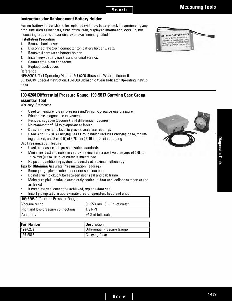
2885158
2582374
1-135
Diagnostic Tools
Measuring Tools
Instructions for Replacement Battery HolderFormer battery holder should be replaced with new battery pack if experiencing any problems such as lost data, turns off by itself, displayed information locks-up, not measuring properly, and/or display shows “memory failed.”Installation Procedure1. Remove back cover.2. Disconnect the 2-pin connector (on battery holder wires).3. Remove 4 screws on battery holder.4. Install new battery pack using original screws.5. Connect the 2-pin connector.6. Replace back cover.ReferenceNEHS0606, Tool Operating Manual, 9U-6700 Ultrasonic Wear Indicator IISEHS9089, Special Instruction, 1U-9800 Ultrasonic Wear Indicator Operating Instruc-tions
199-6268 Differential Pressure Gauge, 199-9817 Carrying Case GroupEssential ToolWarranty: Six Months
• Used to measure low air pressure and/or non-corrosive gas pressure• Frictionless magnahelic movement• Positive, negative (vacuum), and differential readings• Nomanometerfluidtoevaporateorfreeze• Does not have to be level to provide accurate readings• Used with 199-9817 Carrying Case Group which includes carrying case, mount-
ing bracket, and 3 m (9 ft) of 4.76 mm ( 3/16 in) ID rubber tubingCab Pressurization Testing• Used to measure cab pressurization standards• Minimizes dust and noise in cab by making sure a positive pressure of 5.08 to
15.24 mm (0.2 to 0.6 in) of water is maintained• HelpsairconditioningsystemtooperateatmaximumefficiencyTips for Obtaining Accurate Pressurization Readings• Route gauge pickup tube under door seal into cab• Do not crush pickup tube between door seal and cab frame• Make sure pickup tube is completely sealed (if door seal collapses it can cause
air leaks)• If complete seal cannot be achieved, replace door seal• Insert pickup tube in approximate area of operators head and chest199-6268 Differential Pressure GaugeVacuum range 0 - 25.4 mm (0 - 1 in) of waterHigh and low-pressure connections 1/8 NPTAccuracy ±2% of full scale
Part Number Description199-6268 Differential Pressure Gauge199-9817 Carrying Case

2582401
2901319
2582415
1-136
Dia
gnos
tic T
ools
Measuring Tools
6V-7059 Multiple Anvil Micrometer6V-2034 AdapterWarranty: Six Months
• Micrometerusedformeasuringtopflangethicknessoncylinderliners,andalsowith the 6V-2034 Adapter to measure Cat® engine valve lip thickness
• Furnished with 2 anvils — 1 anvil is for measuring parts which can not be mea-sured with a standard micrometer; the other anvil permits the micrometer to be used as a general purpose 0 to 25 mm (0 to 0.98 in) measuring instrument
• When measuring engine valve lips with the 6V-2034 Adapter, refer to the valve dimensions given in the Guideline for Reusable Parts, Form SEBF8034
Part Number Description6V-2034 Adapter6V-7059 Multiple Anvil Micrometer
385-6365 MicrometerWarranty: Manufacturer’s
• Used to measure small thicknesses or diameters• Large, easy to read (0.275 in/7 mm), high-contrast LCD digital readout• LP67 protection against coolant, water, dust and dirt• Noglaresatinchromefinishonthimbleandsleeve• Extremely hard and stable one piece spindle, accurate and smooth operating
one-piece friction thimble• Two 3-volt batteries included for more than one year of normal usage• Micro-lapped carbide measuring faces• Automatic OFF after 20 minutes of nonuse• Metric only• Measurement HOLD button• Ability to zero tool at any position and retain and return to true zero reading of
the micrometer• Resolution .00005 in (0.001 mm)• Accuracies (±.0001 in (±.002 mm))• Measuring capacities 1 in (25 mm)• Does not have 4S232 digital output
Part Number Description385-6365 Micrometer
6V-2012 Gauge Group, Micrometer Depth (in)6V-7030 Gauge Group, Micrometer Depth (mm)Warranty: Six Months
• Contains a complete set of measuring rods from 0 to 228.6 mm (0 to 9 in) which are all stored in the wooden case
• Base: 76.2 mm (3.00 in) wide; uses 3.96 mm (5/32 in) rodsItem Description1 Case (Not available)
Item Part Number Description— 6V-2012 Gauge Group— 6V-7030 Gauge Group2 6V-0088 Rod, 177.8 - 203.2 mm (7 - 8
in)
(Continued)

2582415
2582431
1-137
Diagnostic Tools
Measuring Tools
6V-2012 Gauge Group, Micrometer Depth (in) (Continued)6V-7030 Gauge Group, Micrometer Depth (mm)Warranty: Six Months
Item Part Number Description3 6V-0091 Rod, 203.2 - 228.6 mm (8 - 9
in)Not Shown 316-1188 Rod, 228.6 - 254 mm (9 - 10
in) 1
1 Sold separately
6V-6042 Point GroupWarranty: Six Months
• Has more contact points for the dial indicators• Hasstraightcontactpointsfrom2.18to120.5mm(0.09to4.74in)long,3flat
points, and a 12.7 mm (0.50 in) extension• Has a plastic box with a divided tool holder and space to cut more slots for stor-
age of special points (part numbers and sizes are shown on a chart inside the lid of the box
• Thesecontactpointswillfitalldialindicatorswith4to48threadsbutwillnotfitthe 1P-2103 Dial Indicator
• Comes with 6V-2030 Indicator Extension
Contact Points (Included in 6V-6042)Part Number Size3S-3268 6.4 mm (0.250 in)3S-3269 25.4 mm (1.00 in)3S-3270 44.5 mm (1.75 in)5P-2393 38.1 mm (1.50 in)5P-4160 19.1 mm (0.75 in)5P-4161 69.9 mm (2.75 in)5P-4162 95.3 mm (3.75 in)5P-4163 120.5 mm (4.75 in)5P-4809 50.8 mm (2.00 in)5P-6531 57.2 mm (2.25 in)5P-7261 31.8 mm (1.25 in)5P-7262 63.5 mm (2.50 in)5P-7263 76.2 mm (3.00 in)5S-8086 2.4 mm (0.094 in) 1
6V-2057 3.2 mm (0.125 in) 2
8S-3675 3.1 mm (0.122 in)9S-0229 9.7 mm (0.38 in)9S-8883 12.7 mm (0.50 in)9S-8903 2.4 mm (0.094 in) 3
1 6.4mm(0.25in)diameterflatface2 9.52mm(0.375in)diameterflatface3 12.7mm(0.5in)diameterflatfacewithabevelto9.7mm(0.38in)diameter

2742960
2582480
2582494
1-138
Dia
gnos
tic T
ools
Measuring Tools
Additional Contact Points & Service/Repair Parts
Item Part Number Description-- 6V-6042 Point Group - Contact
Additional Contact Points Available (Sold Separately)1 5P-2057 Contact Point2 1P-5512 Contact Point3 6V-6167 Contact Point4 1P-5513 Contact Point5 5P-2056 Contact Point
Service/Repair Parts (Sold Separately)Not Shown 6V-6045 Case - Plastic, NEEG2061 Accessories Case DecalNot Shown 6V-6043 Block Holder
5P-2170 Dial Bore Gauge GroupWarranty: Six Months
• Gauge and related masters provide accuracy to 0.0025 mm (0.0001 in) for mea-suring all bores in the size range 19.05 - 38.10 mm (0.750 - 1.500 in)
• Particularly useful for measuring the relief valve spool bores in pressure control bodies on 631, 633, 637, 641, 650, 651, 657, 660, and 666 Tractors with eight speed transmissions
Item Part Number Description1 5P-2170 Dial Bore Gauge Group
Master Gauges (available separately)2 5P-2043 Gauge, 19.050 mm (0.7500
in)2 5P-2059 Gauge, 22.225 mm (0.8750
in)2 5P-2169 Gauge, 25.400 mm (1.0000
in)2 5P-2171 Gauge, 27.051 mm (1.0625
in)2 5P-2173 Gauge, 31.750 mm (1.2500
in)2 5P-2174 Gauge, 38.100 mm (1.5000
in)2 5P-2172 Gauge, 28.575 mm (1.1250
in)
1P-3537 Dial Bore Gauge Group for Inch MeasurementsWarranty: Six Months
• Useful for making any critical bore measurement from 50.8 to 203.2 mm (2.0 to 8.0 in)
• Specifically,theyshouldbeusedwhenreconditioningthecylinderboreson1100and3100SeriesEnginesandwhenrefinishingconnectingrodsin137.16mm (5.4 in) bore V8 and V12 Engines
ReferenceGMGO0981, Special Instruction
(Continued)

2582494
2582509
1-139
Diagnostic Tools
Measuring Tools
1P-3537 Dial Bore Gauge Group for Inch Measurements (Continued)Warranty: Six Months
Item Part Number Description1 9U-6615 Size Setting Fixture Group2 1P-3535 Dial Bore Gauge3 5P-6580 Nest Kit (Early gauges
require nest kit if used on latersizesettingfixtures)
-- 1P-3537 Dial Bore Gauge, Inch Measurements
6V-7898 Dial Bore Gauge, Metric; 6V-7899 Size Setting Fixture, Metric6V-7897 Dial Indicator for Converting 1P-3535 Dial Bore Gauge to MetricWarranty: Six Months
• Used for precision metric measurements• Measure all internal diameters from 50 to 200 mm (1.97 to 7.87 in) and depths from 13 to 300 mm (0.51 to 11.81 in) in incre-
ments of 0.002 mm (0.00008 in)• Increased accuracy is needed for applications such as connecting rods where the tolerances are very small• Useofthegaugeissimplifiedbecauseallcurrentspecificationsaregiveninmetricdimensions• 6V-7897 Dial Indicator is available to convert the current 1P-3535 Dial Bore Gauge to the 6V-7898 Dial Bore Gauge (all 1P-
3535 Gauges can be converted except earlier gauges marked “MADE IN ENGLAND”)ReferenceSMHS8253, Special Instruction, instructions for use of the 6V-7898 Dial Bore Gauge and also information for converting the 1P-3535 Gauge to the 6V-7898 GaugeSMHS8254, Special Instruction, instructions for use of the 6V-7899 Size Setting Fixture
Part Number Description1P-3535 Dial Bore Gauge6V-7897 Dial Indicator for Converting 1P-3535 Dial Bore Gauge to Metric6V-7898 Dial Bore Gauge, Metric6V-7899 Size Setting Fixture, Metric

2582525
2582543
1-140
Dia
gnos
tic T
ools
Measuring Tools
Dial Bore Gauge and Master RingsModel: 3600 Engines, Gas and DieselWarranty: Six Months
ReferenceSEBF8109, Guideline for Reusable Parts147-8862 Dial Bore Gauge• Used to measure 3600 Engine cylinder liners• Dial graduated to 0.002 mm• Tool can reach up to 457 mm (18.0 in)147-8860 Master Ring (diesel 280.025 mm [11.0246 in])• Used to calibrate dial bore gauge to 280.025 mm (11.0246
in)• Calibrates gauge for use on diesel engines147-8861 Master Ring (gas 300.00 mm [11.811 in])• Used to calibrate dial bore gauge to 300.000 mm (11.811 in)• Calibrates gauge for use on gas engines
Part Number Description147-8860 Master Ring (diesel 280.025 mm [11.0246
in])147-8861 Master Ring (gas 300.00 mm [11.811 in])147-8862 Dial Bore Gauge
6V-6000 Dial Bore Gauge for Metric Measurements6V-6030 Size Setting FixtureWarranty: Six Months
6V-6030• Precision measuring instrument with a diameter range of 30.0 to 50.8 mm (1.2 to
2 in) graduated in 0.002 mm (0.00008 in) increments• Depth range: 8.5 to 150 mm (0.335 to 5.91 in)• Gauge is especially useful for measuring piston pin bores for 3300 Series En-
gines• Will set or check the dial bore gauge in 0.002 mm (0.00008 in) increments within
its range of 0 to 50 mm (0 to 1.97 in)• Fixture has a magnifying glass for easier readingReferenceSMHS8037, Special Instruction for 6V-6000SMHS8036, Special Instruction for 6V-6030
Part Number Description6V-6000 Dial Bore Gauge for Metric Measurements6V-6030 Size Setting Fixture

2582559
2837011
1-141
Diagnostic Tools
Measuring Tools
245-5829 Battery and Coolant RefractometerModel: AllWarranty: One Year
European Union compliant, CE marked• Used to measures freezing point of coolants plus battery charge condition• Refractometer uses a prism and lens with simple focus adjustment to provide
accurate and repeatable measurements on easy to read scales• Easy to operate• Automatic temperature compensation (ATC)• Requires only 2 or 3 drops of solution• Carrying case and calibration screwdriver included• Reads degrees Centigrade and FahrenheitRange Resolution-60° to 32° F propylene glycol freeze point 10° F-50° to 0° C ethylene glycol freeze point 5° C1.15to1.30specificgravityofbatteryacid
0.01
Part Number Description245-5829 Coolant Test Kit
367-9109 6 Inch Fractional Digital CaliperModel Usage: All machines/modelsWarranty: One year
European Union Compliant, CE Marked• Used to make inside, outside depth and step measurements• Tri-mode digital display; Inches, Millimeters, and Fractions• Auto off• Replacement Battery; LR44• Construction: Carbon FiberSpecificationsRange 0 - 6 in (0 - 150 mm)Resolution 0.0005 in (0.01 m or 1/64 in)Accuracy 0.001 in (± 0.02 mm)Length 38 mm (1.5 in)Width 114 mm (4.5 in)Depth 292 mm (11.5 in)Weight 289.4 gram (0.638 lb)
Part Number Description367-9109 6” Fractional Digital Caliper

2582607
1-142
Dia
gnos
tic T
ools
Measuring Tools
7B-0337 Surface PlateWarranty: Six Months
• Useforcheckingsmallshaftsandbarsforstraightness;checkingflatsurfacesforwarp;andtrimmingrings,bearingcaps,etc.,usingfineemerycloth
• Plate measurements: 304.8 x 330.2 x 38.1 mm (12.0 x 13.0 x 1.5 in)NoteAs this plate is meant for general shop use, its surface is ground but not spot-scraped.
Part Number Description7B-0337 Surface Plate

2582623
2582640
1-143
Diagnostic Tools
Paving Products
Paving Products
4C-5558 Auto Vibration Bypass ControlModel: CB434, CB534 Vibratory CompactorsWarranty: One Year
• Allows vibration mode to operate while machine is standing still for testing and adjusting• Without this tool machine has to be in motion for vibration mode to operate• Consists of ON/OFF switch attached to 3.048 m (10-ft) long cableReferenceKENR1305, Service Manual
Part Number Description4C-5558 Auto Vibration Bypass Control
FT2373 Electrical Displacement Control Test BoxModel: AP-800 (1BF), AP-1200 (2JD) Asphalt Pavers; RR-250 (6ED) Road Reclaimers; SS-250 (6DD) Soil StabilizersWarranty: None
• Tests electrical displacement control (EDC) in Sundstrand hydraulic systems (ground drive pump)• Will move machine if electrical system failure other than EDC• Minimum-maximum resistance: 0 - 250 ohmsUse the parts list and wiring diagram to construct a FT2373 Test Box.For asphalt paving machines only, if an electrical failure causes the brakes to be engaged, use a jumper wire to supply electrical power directly to the brake solenoid. If the brake solenoid has failed, use a portable hydraulic power supply to release the brakes when the machine is to be movedMark the 0 to 250 ohm potentiometer to show the minimum and maximum resistance positions (0 ohms and 250 ohms respectively). The potentiometer should be at the maximum resistance (250 ohms) when the test box is connected to the machine.Operating InstructionsBeforemakingthefollowingchecks,ensurethatthemachineisonflatgroundwithadequateroomformovementforwardandreverse. With the brake off, manually move the pump control valve at the EDC (see the service manual). If the machine moves, the problem is electrical. Proceed with the following checks. If the machine does not move, the problem is in the hydraulic sys-tem and further electrical checks are not necessary1. Ensure proper polarity when connecting large battery clips (7, 8) to the battery.2. Turn the potentiometer (1) to the maximum resistance position (250 ohms).3. Connect the mini-clips (9) to the EDC wiring harness.4. Slowly turn the potentiometer (1) toward the minimum resistance position (0 ohms) until the machine starts to move. To
reverse the direction of travel reverse the switch (2).5. If the machine does not move and/or increase in speed as the potentiometer (1) is turned toward the minimum resistance
position (0 ohms) replace the EDC.6. If the machine moves and increases speed, as the potentiometer (1) is turned toward the minimum resistance position, the
EDC is working correctly. Check for an electrical problem other than the EDC.Item Description Radio Shack Part No.4 14-gauge wire, 4.8 m (15.75 ft) long (4) 5 16-gauge wire, length as required 6 Terminal strip 274-6587 Battery clip (+red) 270-3448 Battery clip (-black) 270-3449 Clip, mini (2) 270-37810 Box, 133.4 x 76.2 x 54.1 mm (5.25 x 3 x 2.13
in)270-238
(Continued)

2582640
2582669
1-144
Dia
gnos
tic T
ools
Paving Products
FT2373 Electrical Displacement Control Test Box (Continued)Model: AP-800 (1BF), AP-1200 (2JD) Asphalt Pavers; RR-250 (6ED) Road Reclaimers; SS-250 (6DD) Soil StabilizersWarranty: None
Item Part Number Description1 8C-7647 Potentiometer, 0 - 250 ohms2 8C-8023 Micro Switch3 081-7580 Resistor, 40 ohms (2)
4C-8758 Test HarnessesModel: E(L)200B, E(L)240B, and E(L)300B ExcavatorsWarranty: One Year
• Allows access to electrical control signals to be checked for correct operation and measurement of voltages, current, resistance and continuity
ReferencesSENR4527, Testing and Adjusting Module for E(L)200BSENR4843, Electronic Power Unit Module for E(L)240BSENR4871, Electronic Power Unit Module for E(L)300BNEHS0546, Tool Operating Manual, Adjustment to Electronic Power Unit Control System
Item Part Number Description Use1 099-0048 Extension Harness In electronic control circuit2 099-0049 Test Harness To check governor control potentiometer3 099-0050 Test Harness To check the Proportional Reducing Valve (PRV) on E(L)200B ExcavatorNot shown 4C-8758 Test Harness To check the PRV on E(L)240B and E(L)300B

2582692
1-145
Diagnostic Tools
Power Train Tools
Power Train Tools
277-2362 Transmission Analyzer III GroupModel: Machines with electrical transmission or pump controlsWarranty: One Year
European Union compliant, CE marked• Replaces discontinued 9U-7500 Transmission Analyzer II
Group• Used to electronically test components on transmission or
pump• Used with dealer supplied computer• Used on Powershift planetary, Powershift countershaft,
Individual Clutch Modulation (ICM), Challenger, H-Series Motor Grader, and Electronic Clutch Pressure Control (ECPC) transmissions
• Used to test and adjust proportional valves which control transmission (connects directly to solenoids with dealer supplied adapters)
• Operates and checks solenoid operation, electronic shift lever operation, and transmission shifts
• Performs automatic or manual testing for shorted or open solenoid coils (can also alert technician to intermittent problems with solenoids)
• Analyzer can activate solenoids in a timeline sequence• Modulates current to 1 or all activated solenoids at any
point in time• Analyzer outputs pulse width modulated (PWM) current
(required for Challenger and ECPC transmissions)• Determines if shift lever is functioning correctly on trans-
missions not controlled by autoshift electronic control feature
• Capable of testing electronically actuated pumps installed on a hydraulic test bench by energizing the solenoids inside the pump
• Uses PC based software to control transmissions allowing easy updates to support new transmissions, as they are released
• Software updated annually to accommodate New Produc-tion Introduction Software Subscription NETG5048
• PC software with easy to use graphic interface provides step-by-step instruction for analyzer operation
• Allows use of mouse, rollerball, touchpad, and keyboard controls
• USB communications cable (included) allows for quick easy connection between analyzer and dealer supplied PC
• Designed and built for harsh shop environmentReferenceNEHS0996 Tool Operating ManualNETG5048 Annual Software Subscription, Bench Testing Hy-draulic ComponentsPart Number Description— Hinged Hard Shell Carry Case
(Continued)

2582692
2742212
1-146
Dia
gnos
tic T
ools
Power Train Tools
277-2362 Transmission Analyzer III Group (Continued)Model: Machines with electrical transmission or pump controlsWarranty: One Year
Part Number Description1U-9485 Power Cable277-2362 Transmission Analyzer III
Group286-0755 USB Communications Cable
Optional Tools1U-9479 Gear Shift Test Adapter Cable1U-9480 Gear Shift Test Adapter Cable1U-9482 Test Cable (ICM)1U-9483 Test Cable (Challenger)
Part Number DescriptionOptional Tools (Continued)
256-7623 Dozer Speed Sensor Cable300-4993 Adapter Cable (17-pin to
14-pin) some R and T Series Track-Type Tractors
307-3542 Transmission Analyzer Adapter Cable
9U-7495 Test Cable (Wheel Loader)9U-7496 Test Cable9U-7497 Test Cable9U-7498 Extension Cable
Specifications
AC power 110 - 240 VACMinimum current required 10 ampsPower cord 231 cm (91 in) long286-0755 USB Cable 203 cm (80 in) longOperating temperature range -18 to 60° C (0 to 140° F) ambient airStorage temperature range -40 to 60° C (-40 to 140° F) ambient airOvercurrent protection Current limiting electronic circuitShort protection 30 amp quick-trip circuit breakerPC software UpgradableComputer operating system Windows 2000 or XPRequired RAM 1 MBMinimum software required Intel Pentium II 333 MHz processor or higher 128 MB RAM or higher 4.3 GB hard disk or higher CD drive or third generation DVD drive 15 in or larger Super VGA adapter and monitorSuggested pointing device Mouse, trackball, or touchpadCase size 52 x 45 x 22 cm (20.5 x 17.5 x 8.5 in)Tester size 36 x 32 x 15 cm (14.25 x 12.5 x 6 in)Group weight 6 kg (13.8 lb)Tester weight 4 kg (8.9 lb)
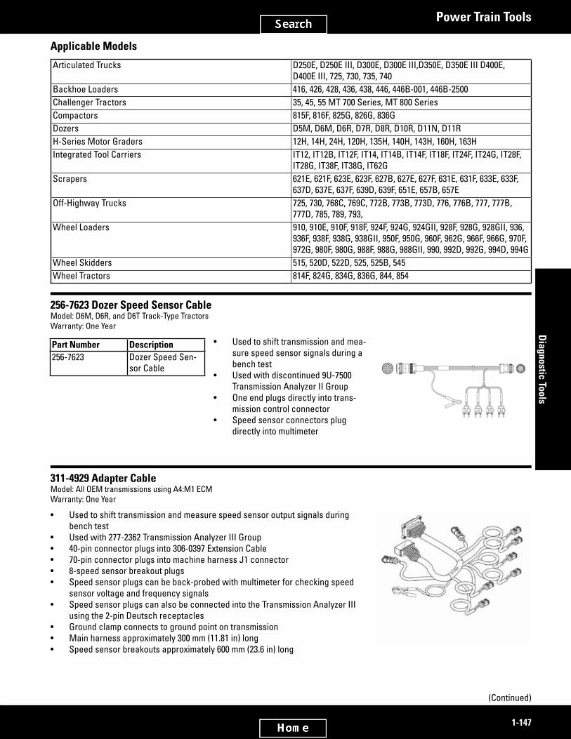
2742259
2582737
2582757
1-147
Diagnostic Tools
Power Train Tools
Applicable Models
Articulated Trucks D250E, D250E III, D300E, D300E III,D350E, D350E III D400E, D400E III, 725, 730, 735, 740
Backhoe Loaders 416, 426, 428, 436, 438, 446, 446B-001, 446B-2500Challenger Tractors 35, 45, 55 MT 700 Series, MT 800 SeriesCompactors 815F, 816F, 825G, 826G, 836GDozers D5M, D6M, D6R, D7R, D8R, D10R, D11N, D11RH-Series Motor Graders 12H, 14H, 24H, 120H, 135H, 140H, 143H, 160H, 163HIntegrated Tool Carriers IT12, IT12B, IT12F, IT14, IT14B, IT14F, IT18F, IT24F, IT24G, IT28F,
IT28G, IT38F, IT38G, IT62GScrapers 621E, 621F, 623E, 623F, 627B, 627E, 627F, 631E, 631F, 633E, 633F,
637D, 637E, 637F, 639D, 639F, 651E, 657B, 657EOff-Highway Trucks 725, 730, 768C, 769C, 772B, 773B, 773D, 776, 776B, 777, 777B,
777D, 785, 789, 793,Wheel Loaders 910, 910E, 910F, 918F, 924F, 924G, 924GII, 928F, 928G, 928GII, 936,
936F, 938F, 938G, 938GII, 950F, 950G, 960F, 962G, 966F, 966G, 970F, 972G, 980F, 980G, 988F, 988G, 988GII, 990, 992D, 992G, 994D, 994G
Wheel Skidders 515, 520D, 522D, 525, 525B, 545Wheel Tractors 814F, 824G, 834G, 836G, 844, 854
256-7623 Dozer Speed Sensor CableModel: D6M, D6R, and D6T Track-Type TractorsWarranty: One Year
• Used to shift transmission and mea-sure speed sensor signals during a bench test
• Used with discontinued 9U-7500 Transmission Analyzer II Group
• One end plugs directly into trans-mission control connector
• Speed sensor connectors plug directly into multimeter
Part Number Description256-7623 Dozer Speed Sen-
sor Cable
311-4929 Adapter CableModel: All OEM transmissions using A4:M1 ECMWarranty: One Year
• Used to shift transmission and measure speed sensor output signals during bench test
• Used with 277-2362 Transmission Analyzer III Group• 40-pin connector plugs into 306-0397 Extension Cable• 70-pin connector plugs into machine harness J1 connector• 8-speed sensor breakout plugs• Speed sensor plugs can be back-probed with multimeter for checking speed
sensor voltage and frequency signals• Speed sensor plugs can also be connected into the Transmission Analyzer III
using the 2-pin Deutsch receptacles• Ground clamp connects to ground point on transmission• Main harness approximately 300 mm (11.81 in) long• Speed sensor breakouts approximately 600 mm (23.6 in) long
(Continued)

2582757
2582781
2582801
2582818
1-148
Dia
gnos
tic T
ools
Power Train Tools
311-4929 Adapter Cable (Continued)Model: All OEM transmissions using A4:M1 ECMWarranty: One Year
Part Number Description311-4929 Adapter Cable
304-9169 Adapter Cable AssemblyModel: TH48FT-E70 Oil-Field TransmissionWarranty: One Year
• Used to shift transmission during bench test• Used with 277-2362 Transmission Analyzer III Group and 9U-7498 Extension
Cable• Connects to 31-pin 9U-7498 Extension Cable, 17-pin transmission bulkhead con-
nector, and 2-pin lock-up clutch solenoid receptacle• Ground clamp connects to ground point on transmission• Overall length: 30 cm (11.8 in)• Material: 18 gauge wire
Part Number Description304-9169 Adapter Cable Assembly
306-0397 Extension Adapter CableModel: All models with electronic controlsWarranty: One Year
• Used with 277-2362 Transmission Analyzer III Group and individual machine test adapter cables that have speed sensor capability
• Provides longer connection between machine test adapter cable and Transmis-sion Analyzer III
• Speed sensor breakout cable allows sensor readouts with Transmission Ana-lyzer III software
Part Number Description306-0397 Extension Adapter Cable
305-7401 Adapter CableModel: 777F Off-Highway TruckWarranty: One Year
• Used to shift transmission and measure speed sensor outputs during bench test• Used with 277-2362 Transmission Analyzer III Group and 306-0397 Extension
Cable• Adapter connects 306-0397 Extension Cable to the transmission bulkhead con-
nector• Speed sensor breakouts allow multimeter readouts• Enables technician to monitor output speed sensors via Transmission Analyzer
III• Ground clamp connects to ground point on transmission• Main harness length: 30 cm (11.8 in)• Speed sensor breakout harness length: 60 cm (23.6 in)
Part Number Description305-7401 Adapter Cable

3041651
2582840
3055011
1-149
Diagnostic Tools
Power Train Tools
FT3194 Transmission Wire HarnessModel Usage: 777G Off-Highway TruckWarranty: Manufacturer’s
• Used to connect to the internal transmission harness to avoid connection problems when intermediate harness is unavail-able for test
• Connects intermediate speed sensor to Transmission Analyzer III to display intermediate speed during test• Required to help troubleshoot transmission on the 777GSpecificationsDimensions 40 cm (15.8 in)
304-9164 Adapter CableModel: 773-775F Off-Highway TruckWarranty: One Year
• Used to shift transmission and measure speed sensor outputs during bench test• Used with 277-2362 Transmission Analyzer III Group and 306-0397 Extension
Cable• Adapter connects 306-0397 Extension Cable to the transmission bulkhead con-
nector• Speed sensor breakouts allow multimeter readouts• Enables technician to monitor output speed sensors with Transmission Analyzer
III• Ground clamp connects to ground point on transmission• Main harness length: 30 cm (11.8 in)• Speed sensor breakout harness length: 60 cm (23.6 in)
Part Number Description304-9164 Adapter Cable
FT3211 Adapter CableModel Usage: 773F, 775F Off-Highway TruckWarranty: None
• Used to shift transmission and measure speed sensor outputs during bench test• Used with 277-2362 Transmission Analyzer III Group and 306-0397 Extension
Cable• Adapter connects 306-0397 Extension Cable to the transmission bulkhead con-
nector• Used to connect to newer transmission harness assemblies referenced in
SEPD1328• Speed sensor breakouts allow multimeter usage• Enables technician to monitor output speed sensors with Transmission Analyzer
III• Ground clamp connects to ground point on transmission• Main harness length: 30 cm (11.8 in)• Speed sensor breakout harness length: 60 cm (23.6 in)• Modificationof304-9164ReferenceSEPD1328, Service Magazine

2921901
2582862
2582884
1-150
Dia
gnos
tic T
ools
Power Train Tools
333-6413 Adapter CableModel Usage: 793FWarranty: One Year
• Used to shift transmission and measure speed sensor outputs during bench test• Used with 277-2362 Transmission Analyzer III Group and 306-0397 Extension
Cable Adapter• Connects 333-6413 extension cable to the transmission bulkhead• Speed sensor breakouts allow multimeter readouts• Capability to monitor output speed sensors with Transmission Analyzer III• Ground clamp connects to ground point on transmission
Part Number Description333-6413 Adapter Cable
306-6388 Adapter Cable AssemblyModel: M-Series Motor GradersWarranty: One Year
• Used to shift transmission and measure speed sensor outputs during bench test• Used with 277-2362 Transmission Analyzer III Group and 306-0397 Extension
Cable• Adapter connects 306-0397 Extension Cable to the parking brake solenoid, shift
solenoid, and speed sensor connectors on transmission• Ground clamp connects to ground point on transmission• Speed sensor breakouts allow for multimeter readouts• Enables technician to monitor output speed sensors using Transmission Ana-
lyzer III• Main harness length: 30 cm (11.8 in)• Speed sensor breakout harness length: 60 cm (23.6 in)
Part Number Description306-6388 Adapter Cable Assembly
307-3542 Transmission Analyzer Adapter CableModel:D11RTrack-TypeTractorsSerialNumberPrefix7PZ,9TR,9XR,andAAFWarranty: One Year
• Used to adapt 256-7623 Speed Sensor Cable to transmissions listed above• Allows transmission to be tested with Transmission Analyzer II and III• Adapts 17-Pin connector on speed sensor cable to 14-Pin connector on trans-
mission• Cable length: 30 cm (11.8 in)
Part Number Description307-3542 Transmission Analyzer Adapter Cable

2582903
2582927
2582950
1-151
Diagnostic Tools
Power Train Tools
1U-9100 Adapter Cable (Challenger to PC)Model: Challenger 35, 45, and 55Warranty: One Year
• Used to connect a personal computer into the Challengers on-board electronic system
• Used with personal computer• Cable connects RS232 port on computer to Diagnostic and Maintenance
(D.A.M.) connector on Challenger• Cable allows Electronic Technician (ET) software to read fault codes, delete
fault codes (where allowed), and change vehicle parameters• Cable comes complete with communication adapter which allows computer to
communicate with Challenger’s electronic system• Cable length: 2.1 m (7.0 ft)• Computer connection: 9-pin serial
Part Number Description1U-9100 Adapter Cable (Challenger to PC)
4C-4068 Extension CableModel: 621E, 623E, 627E, 631E, 637E, 651E, 657EWarranty: One Year
• 14-foot long extension cable that enables serviceman to position ICM control box in cab while troubleshooting transmis-sions
• Make troubleshooting safer and easier
Part Number Description4C-4068 Extension Cable
139-5210 Extension Cable Assembly (ARC/EPTC II)Model: See List BelowWarranty: One Year
• Extension cable for Automatic Retarder Control (ARC) used on 769D, 771D, 773D, 775D, 776D, 777D, 785B, 789B, 793B, and 793C Off-Highway Trucks; and Electron-ically Programmable Transmission Control (EPTC II) used on 769D, 771D, 773D, 775D, 776D, 777D, 785B, 789B, 793B, and 793C Off-Highway Trucks; D250E, D300E, D350E, and D400E Articulated Trucks; and 621F, 623F, 627F, 631E, 633E, 637E, and 657E Wheel Tractor Scrapers
• Connects to 10-pin sure seal connector on ARC or EPTC II• Two additional connectors allow 4C-8195 Control Service Tool and discontinued
7X-1700 Communication Adapter to be connected• Allows serviceman to position ARC and EPTC II in cab while troubleshooting• Overall length: 4.3 m (14 ft)
Part Number Description198-1758 Calibration Group139-5210 Extension Cable Assembly (ARC/EPTC II)

2582969
3041511
2582999
1-152
Dia
gnos
tic T
ools
Power Train Tools
198-1758 Calibration GroupEssential ToolSMCS Code: 5084-524Model: 621G, 623G, 627G, 631G, and 637G ScraperWarranty: Six Months
• Used to calibrate electro-hydraulic implement control system• Used with Cat® Electronic Technician (ET) software• Ensuresefficientoperationofimplementsystem• Overall length: 650 mm (25.6 in)ReferenceRENR1528, RENR1534, and RENR1593 Service Manual Modules198-6593 Calibration Instructions
Service/Repair PartsPart Number Description142-2763 Coupler Assembly202-8022 Switch Assembly276-8158 Harness Assembly3J-7354 Seal - O-ring -
STOR for 8C-3446 (not pictured)
3K-0360 Seal - O-ring - STOR (SAE 3/4 - 16)
8C-7325 Adapter
369-4187 Calibration GroupModel Usage: 621H, 623H, 627H, 631HWarranty: Six Months
• Used to calibrate electro-hydraulic implement control valve for 620H Series Wheel Tractor Scrapers
• Not for G models. G models use the 198-1758 Calibration Group.
Serviceable PartsPart Number Description369-4188 Calibration Cable Assembly 75 cm (30 in)344-7391 Pressure Sensor Group214-7568 O-ring STOR Seal 11.89 mm (9/16 in)214-7566 O-ring STOR Seal 8.92 mm (7/16 in)142-2763 Coupler Assembly4I-0899 STOR Boss/ STOR Port Fitting
4C-5974 Adapter CableModel: Machines with military-type connectorsWarranty: One Year
• Used to adapt military-type connector, previously used on majority of Cat® ma-chines, to Sure Seal connector
• Standard harness with military-type connectors can now be used with the ser-viceablereplacementsthatuseSureSealconnectorswithoutanymodificationof wiring harness
• Testing and analysis equipment can be used on hardware with new Sure Seal connectors
Part Number Description4C-5974 Adapter Cable

2583016
2742355
1-153
Diagnostic Tools
Power Train Tools
FT2796 Breakout HarnessModel: 700 Series Articulated TruckWarranty: None
• Used to connect a signal generator to transmission output speed sensor
• Made from 8T-8666 Connector Kit and other miscellaneous parts
• Simulates ground speed
Assembly Instructions1. Obtain 8T-8666 Connector Kit.2. Cut 50 mm (1.97 in) off Green wire to make the same length as Black wire.3. Splice 16GA Black wire to Black wire of 8T-8666 Harness.4. Cut this black wire on the side of the splice closest to the 3-pin connector.5. Splice or solder each end of the severed wire to one of the capacitor leads.6. Splice 16GA Green wire to Green wire of 8T-8666 Harness.7. Crimp 8T-8729 Pins to Green and Black wires.8. Cover splices with heat shrink wrap.9. Insert pins into receptacles, Black to 1 and Green to 2.10. Insert wedges into receptacles. Tape unused Orange wire to harness.Parts Required for AssemblyItem Part Number Description Qty.2 — 16 GA Green Wire
25 cm (9.84 in) long1
3 — 16 GA Black Wire 25 cm (9.84 in) long
1
4 — Shrink Wrap 18 — Capacitor (100 V, 1
μFd)1
— Possible suppliers or other equivalent:
— Digi-Key 399-4427 ND
— Mouser Electronics 80-C340C105K1R
Item Part Number Description Qty.1 8T-8666 Connector Kit 15 3E-3364 Receptacle As-
sembly2
6 3E-3365 Wedge 27 8T-8729 Connector Pin 4

2583047
2583066
1-154
Dia
gnos
tic T
ools
Power Train Tools
232-1065 Cable AdapterEssential ToolModel: 740 Articulated TruckWarranty: One Year
• Used to connect transmission ICM solenoid to harness from discontinued 9U-7500 Transmission Analyzer II
• Adapts two-pin, military-type connector to two-pin Deutsch DT connector• Allows discontinued 9U-7500 Transmission Analyzer II to be used on newer
articulated truck transmissions• Overall length: 300.0 mm (11.8 in)
Part Number Description232-1065 Cable Adapter
308-2506 Adapter HarnessModel: D6K Track Type TractorWarranty: Six Months
• Used to electrically connect cab to machine while cab is removed• Used with Cat® ET to perform remote hystat stall test• Includes jumpers for 31-pin and 40-pin cab connectors, battery, alternator, and
ground connections• Uses machine speed sensor inputs to maintain machines’ safety features• Prevents machine parking brake from being disengaged• Ring terminals for battery, alternator, and ground connections provide safe,
reliable, high-current connections (additional bolts required to connect ring terminals)
• Overall length: 6.1 m (20 ft)• Approximate weight: 13.5 kg (30 lb)
Part Number Description308-2506 Adapter Harness

2744815
1-155
Diagnostic Tools
Speed Measuring Tools
Speed Measuring Tools
9U-7400 Multitach II Group, 9U-7401 Multitach II9U-7402 Multitach II Photo GroupModel: All Cat® ProductsWarranty: One Year
European Union compliant, CE marked• Used to measure RPM, frequency, and engine set point —
combines 3 instruments into one• Engine set point indicator captures and displays set point
RPM• Hz frequency meter measures gen set or other signal
frequency• Easy to use photo pickup for fast RPM measurement• 2 digital displays show Input 1 and Input 2 values simulta-
neously — eliminates switching screens• Displays minimum, maximum, and difference values of
inputs• Displays difference between Input 1 and Input 2• Backlit display for operation in low light conditions• Optional RS232 output available for sending data directly
to printer• Adjustable pulses per revolution• Operated by rechargeable battery — designed with low
battery indicator and internal battery voltmeter• Accepts many different types of pickups (including most
pickups used with former Multitach II)• Program each input separately with different PPR (Pulses
Per Revolution) values for each — different pickups can be used simultaneously
• Stays pre-programmed to values last used — displays values when turned on
ReferenceNEHS0605, Operating ManualRPM measurement range 1 - 9999 RPMMeasurement accuracy ±1 RPMPulses per revolution 0.1 - 256 PPR (selectable)Frequency measurement range
0-9999 Hz
Frequency measurement accuracy:0 - 999.9 Hz ±0.5 Hz1000 - 9999 Hz ±1.0 HzSet point measurement Set point — 20 RPM = full load
RPMOverrun indicator 0 - 10% rack contactSet point RPM 11% rack contact (RPM held
on display)Overrun and lug off 11 - 74% rack contactLug indicator 75 - 100% rack contact

2583091
1-156
Dia
gnos
tic T
ools
Speed Measuring Tools
9U-7400 Multitach II Group
Item Part No. Description3 — Storage for 3 spare AA size
batteries12 — Storage for additional
Tachometer Generator13 — Storage for additional
Tachometer Drive Group20 — Storage for additional
photo pickup magnetic base
22 — Storage for 2 spare AA size batteries
23 — NEEG2593 Inside Lid Decal24 — NEHS0605 Operating
Instructions
Item Part No. Description1 9U-7505 High Voltage Adapter (600 V Max)2 4C-3024 Battery Charger4 9U-5140 LED Photo Pickup5 9U-7401 Multitach II6 6V-6045 Case - Plastic NEEG2061 Accessories Case Decal7 1U-6605 Retro-ReflectiveTape,12mmx1.5m(0.5inx5.0ft)roll8 6V-3138 Extension Rod for Magnetic Base9 9U-7506 Magnetic Adapter Cable10 8T-5111 Rack Adapter Cable11 5P-7360 Tachometer Generator14 5P-1759 Tachometer Drive Group (additional parts in accessory case)15 9U-7508 Foam Insert16 6V-2198 Cable Assembly, 5.5 m (18.0 ft)17 6V-7145 Case, NEEG2573 Group Label on lid of 9U-7400 Group18 6V-7072 Lead Kit - Test ( for use with high voltage adapter)19 1P-7446 Rack Cable, 5.5 m (18.0 ft)21 6V-3137 Magnetic Base for Photo Pickup-- 9U-7400 Multitach II Group

2744910
2745001
1-157
Diagnostic Tools
Speed Measuring Tools
9U-7402 Multitach II Photo Group
Item Part No. Description1 — Storage for 5 spare AA size
batteries12 — NEEG2594 Inside Lid Decal13 — NEHS0605 Operating
Instructions
Item Part No. Description2 9U-5140 Pickup - LED Photo3 9U-7401 Multitach II4 6V-6045 Case - Plastic, NEEG2061 Accessories Case Decal5 1U-6605 Retro-ReflectiveTape,12.5mm(0.5in)x1.5m(5.0ft)long6 6V-3138 Extension Rod for 6V-31377 6V-3072 Case - Plastic, NEEG2574 Group Decal on lid (9U-7402 Group)8 6V-2198 Extension Cable (X8)9 9U-7507 Foam Insert10 6V-3137 Magnetic Mounting Base for 9U-514011 4C-3024 Battery Charger-- 9U-7402 Multitach II Photo Group
Optional Accessories (Sold Separately)
Item Part No. Description1 4C-9499 RS232 Output Adapter2 155-5175 AC Clamp-on Probe (use with 9U-7505 High Voltage Adapter or 9U-5265 Banana Plug Adapter to
measure Hz)3 155-5176 AC/DC Clamp-on Current Probe (use with 9U-7505 High Voltage Adapter or 9U-5265 Banana
Plug Adapter to measure Hz)4 9U-5215 Tool Case, Soft (not as shown)5 8T-5297 Extension Cable 0.9 m (3.0 ft)6 9U-5265 Adapter (connects 2 banana plugs to 9U-7506 magnetic adapter cable)7 6V-0093 RetroReflectiveTape,12.0mm(0.5in)widex15.0m(50ft)longroll8 4C-6919 RetroReflectiveTape,25mm(1in)widex2.5m(100in)longroll,withhoneycombpattern
design9 1 4C-6821 Injection Line Speed Pickup Group (for Multitach or Data Logger)11 1 6V-4950 Injection Line Speed Pickup Group (for Multitach only)
(Continued)

2745001
2583163
1-158
Dia
gnos
tic T
ools
Speed Measuring Tools
Optional Accessories (Sold Separately) (Continued)
Item Part No. Description12 1U-7445 NiCad (Nickel Cadmium) Rechargeable Battery, AA (packaged singly) 2
13 1U-9533 Alkaline Non-Rechargeable Battery, AA (package of 96) 2
14 8L-4171 Magnetic Pickup (general purpose)15 8T-5184 Magnetic Pickup, 88.9 mm (3.5 in) long x 6.35 mm (0.25 in)16 6V-2197 Magnetic Pickup, 114.3 mm (4.5 in) long x 6.35 mm (0.25 in)17 8T-5185 Magnetic Pickup, 177.8 mm (7.0 in) long x 6.35 mm (0.25 in)18 6V-2199 Pickup Adapter, 6.35 mm (0.25 in) diameter x 1/8 in NPT19 6V-3093 Pickup Adapter, 6.35 mm (0.25 in) diameter x 1/4 in NPT
Not Shown-- 1U-6605 12.2mm(0.5in)RetroReflectiveTape(1),1524mm(5ft)longroll
1 Item 10 is part of this group2 Five batteries are required to power Multitach II
5P-1759 Tachometer Drive GroupModel: All ModelsWarranty: Six Months
• Used on engines with ENM Service Meters including engines with Sleeve Me-tering Fuel Systems
• To use 5P-1759 Drive Group, service meter is removed and drive group installed• On 5.4 inch bore engines not equipped with tachometer drive group, 5P-1758
Shaft Assembly must be used
Item Part Number Description Use1 1W-2316 Adapter Assembly For all engines with ENM Service Meters1 4M-8308 Seal (outside) —2 5P-1758 Shaft Assembly With 1W-2316 for 5.4 in bore V—engines3 4N-0538 Coupling With 1W-2316 and 5P-0537 for engines with Sleeve
Metering Fuel Systems4 5P-0537 Hard Washer 4N-0538 (5P-0537 Washer, discontinued, is not
needed with later 1W-2316 Adapter Assembly)5 9S-3032 Clamp (2) —6 9S-0211 Clamp (2) —-- 5P-1759 Tachometer Drive Group (additional
parts in accessory case)—

2583188
2583202
2583221
1-159
Diagnostic Tools
Speed Measuring Tools
168-7727 Battery Cover GroupWarranty: One Year
• Replacement battery cover kit for the following hand held diagnostic tools which have external battery access: 9U-7401 Multitach II 168-7721 Ultrasonic Wear Indicator III
Item Description1 Battery Screw Cover2 O-ring Seal3 Battery Cover4 GasketNot shown Battery Clip, Single (2) Battery Clip, Dual (4)
Part Number Description168-7727 Battery Cover
Group
211-1773 Drive Motor Speed Pickup Breakout-T211-1774 Engine Speed Sensor Breakout-TModel: D3G, D4G, D5G Track-Type TractorWarranty: One Year
• Used to monitor drive motor speed pickup and engine speed sensor• Used with DataView• 211-1773 connects between machine harness and engine speed sensor (mag-
netic pickup)• 211-1774 connects between machine harness and drive motor speed pickup
(Hall-effect sensor)
Part Number Description211-1773 Drive Motor Speed Pickup Breakout-T211-1774 Engine Speed Sensor Breakout-T
FT1808 Magnetic Input Adapter CableModel: All ModelsWarranty: None
• Permits easier use of discontinued 6V-2100 Multitach or 9U-7400 Multitach II to check engine or alternator RPM
• Used on engines equipped with magnetic pickup which is used as RPM signal for electronic overspeed switch or electronic governor
ReferenceSENR2945, Electronic Monitoring System (EMS) Service Manual (contains additional information to check alternator “R” terminal output)Operating InstructionsTo measure engine RPM on the multitach, connect the lug end of the cable to the magnetic pickup output signal lead for the magnetic pickup. Connect the plug end of the cable to the 5P-7362 Magnetic Input Cable on the multitach. No ground connection is needed if the engine battery is used as thepowersourceforthemultitach.Usethenumberofflywheelteethasthe P/REV (pulses per revolution) number on the multitach.
(Continued)

2583221
2583234
2583252
1-160
Dia
gnos
tic T
ools
Speed Measuring Tools
FT1808 Magnetic Input Adapter Cable (Continued)Model: All ModelsWarranty: None
To measure alternator RPM, connect the lug end of the cable to the “R” terminal on the alternator. Connect the plug end of the FT1808 Cable to the 5P-7362 Mag Input Cable that is connected to the multitach mag input. This method gives the alternator RPM which is a ratio of the engine RPM. See the chartfortheP/REVnumbersforthespecificalternatortobechecked.Alternator Type Multitach P/RevCat® 6DELCO 10-20 DI 7DELCO 25-30 SI 8
5P-0935 Tachometer Drive Adapter GroupModel: 910. 931, D3, 3204Warranty: One Year
• Used with Tachometer Drive Group for checking engine speed on 3204 Engine in D3 Tractors, 910 Wheel Loaders, and 931 Track Loaders (discontinued 7M-6006 Groupmustbemodifiedbyremovingplateandmachininghousingtodimensionshown)
Item Part Number Description1 5P-0933 Adapter (Part of 5P-0935)2 5P-0934 Shaft (Part of 5P-0935)3 7M-6006 Drive Group— 5P-0935 Tachometer Drive Adapter Group
8N-5945 Adapter AssemblyModel: 943, 953, 3204Warranty: Six Months
• Used for measuring engine speed on 3204 Engines, 10X1-2935, in 943 and 953 Loaders
• 90° drive adapter assembly installed on engine timing gear cover• Used with 5P-7360 Tachometer Generator; 4M-8303 Seal and two 9S-3032
Clamps also required for installation of adapter assembly
Part Number Description8N-5945 Adapter Assembly

2583272
2583292
2583307
2583322
1-161
Diagnostic Tools
Speed Measuring Tools
6N-1345 Tachometer Drive AdapterModel: 943, 953, 215, 3204Warranty: Six Months
• Used for measuring engine speed on later 3204 Engines, 10X-2396-Up, in 943 and 953 Loaders and 215 Excavators (different adapter needed for later engines because of change to camshaft)
• Also required for adapter installation: 4M-8303 Seal, 5P-1758 Shaft Assembly, two 9S-3032 Clamps, two 0S-1617 Bolts and two 9M-1974 Washers
Part Number Description6N-1345 Tachometer Drive Adapter
7N-8929 Cable ConnectorModel: All ModelsWarranty: Six Months
• Used to connect tachometer drive cable to 9S-3047 Tachometer Generator (included in 1P-5500 Phototach Group) on engine applications where access to tachometerdriveisdifficult;disconnecttachometerdrivecableattachometerandusethisfitting
Part Number Description7N-8929 Cable Connector
1U-5550 Oil Pressure Adapter GroupModel: XNIP Peugeot EnginesWarranty: Six Months
• Used to measure oil pressure on XNIP Peugeot Engines; these engines are found on several models of Cat® lift trucks; the 1U-5550isinstalledinplaceoftheoilpressuresolenoidintheoilfilterbase;the1U-5550providesa9/16in18-2B(SAENo.6)port for pressure measurement purposes
Part Number Description1U-5550 Oil Pressure Adapter Group
FT0907 AdapterModel: D342, D343, D346, D348, D349, D353, D379B, D398B, D399Warranty: None
• Used with reversible variable speed drill and tachometer to bench set mechani-cal overspeed controls
• Material: mild steel

2583344
2583393
2583364
1-162
Dia
gnos
tic T
ools
Speed Measuring Tools
1U-9139 Universal Fuel Line PickupModel: All non-unit-injected Cat® diesel enginesWarranty: One Year
• Used with discontinued 6V-2100 Multitach (as accessory part for 6V-4950 Pickup Group) to measure diesel engine speed
• Works on fuel lines with remote unit pump group, on all pre-combustion cham-ber fuel systems and on some smaller direct injection fuel systems
• Not applicable to unit injected 3500 and 3600 Engines• Adaptable to different fuel line sizes from 5.5 mm (0.22 in) to 7.0 mm (0.28 in) size
rangeReferencesSEHS8029, Special InstructionSEHS7807-03, Special Instruction
Item Part Number Description1 1U-9139 Universal Fuel Line Pickup2 6V-6113 Amplifier
161-8384 Battery ChargerModel: All ModelsWarranty: One Year
• Used to recharge nickel cadmium batteries on newer hand-held Photo-Tach• Used with 1U-7771 Photo-Tach, part of discontinued 1U-6602 Photo-Tach GroupReferenceSEHS8854, Special Instruction, Using the 1U-6602 Photo-Tach GroupCharger connector Barrel typeConnector OD 5.6 mm (0.22 in)Connector ID 2.5 mm (0.10 in)Center pin (ID) polarity Negative
Part Number Description161-8384 Battery Charger
351-8635 Tachometer GroupModel: All ModelsWarranty: Manufacturer’s
European Union compliant, CE marked• Replaces canceled 1U-6602 Photo-Tach Group• UsedtomeasureRPMbydirectingclass2laserlightsourceontoreflectivetape• Reflectivetapecanbeaffixedtoanyrotatingcomponent• Operatesupto8meters(25ft)fromreflectivetarget• Lightweight, compact design allows direct line of sight of both target and display at the same time• 32 function tachometer/ratemeter, totalizer/counter and timer (stopwatch)• Programmable in both Metric and English units• Autorangingandfixeddecimalreadouts(userselectable)• On-target and low battery indicators• Ergonomic non-slip rubber surface for one hand operation• Features tripod mounting bushing and “Power On” lock for hands free operation• Kitincludespocketlasertach,carrycasewithfoaminsert,reflectivetape,twoAAalkalinebatteries,operatingmanual
(English,French,Spanish),andN.I.S.T.traceablecertificateofcalibration
(Continued)

2583364
1-163
Diagnostic Tools
Speed Measuring Tools
351-8635 Tachometer Group (Continued)Model: All ModelsWarranty: Manufacturer’s
Display 5 digits, 5 alpha-numeric LCDOptical Range 5 to 200,000 RPMContact Range 0.5 to 20,000 RPMOptical Accuracy ±0.01% of reading (subject to intensity of ambient light)Contact Accuracy ±0.05% of reading in rpm (also reads in units per second and
units per hour)Totalizer 1- 999,990 (events or length)Timer 99:59.9 (minutes, seconds, tenths)Resolution 0.001 to 10 RPM (range dependent)Operating Range 5 to 762 cm (2.0 inches to 25.0 feet) ±70° from perpendicular
(subject to intensity of ambient light)Memory maximum, minimum, and last readingPower Two 1U-9533 AA 1.5 VDC batteries (30 continuous hours)Temperature Range 5° to 40° C (0° to 100° F)Humidity Range 80% relative humidity up to 31° C (88° F)Dimensions (H x W x D) 17.6 x 6.1 x 4.0 cm (6.92 x 2.4 x 1.6 in)Weight 210 g (7.4 oz)Classification class2laserproduct-1mWmax@850nmclassifiedtoIEC
60825-1: 2001
Part Number Description351-8635 Tachometer Group
Service/Repair Parts1U-6605 Retro-ReflectiveTape,12.5mm(0.5in)x1.5m(5.0ft)long1U-9533 AA Alkaline Battery , non-rechargeable, package qty 96 (5
required to power Indicator III)

2583412
2583435
1-164
Dia
gnos
tic T
ools
Temperature Measuring Tools
Temperature Measuring Tools
349-4202 Infrared and Contact Thermometer (12:1 Ratio)Model: AllWarranty: Manufacturer’s Two Year
European Union compliant, CE marked• Used to determine surface temperature using non-contact temperature mea-
surement with a distance-to-spot ratio of 12:1• Thermometer also supports contact-temperature measurement (compatible
with all standard mini-connector type K thermocouples)• Measures temperatures from -40 to 550° C (-40 to 1022° F)• Single-point laser sighting• Easy emissivity adjustment (Lo, Med, Hi) for measuring pipes and other shiny
materials more accurately• Lightweight [just 340 g (12 oz)] and portable• MIN, MAX, and DIF functions help quickly identify problems• Battery life of 13 hours (laser and backlight used 50%)• Includes K-Type thermocouple Velcro® pipe probe, durable hard case, two AA
batteries, Getting Started guide in six languages, and Users Manual on CD in sixlanguages(English,Spanish,French,German,Portuguese,andSimplifiedChinese)
Temperature Range -40° C to 550° C (-40° F to 1022° F)Accuracy ± 1% or ± 1° C (2° F); <0 °C (32° F), ± 1° C
(2° F) ± 0.1°/1° (Assumes ambient operat-ing temperature of 23 to 25° C (73 to 77° F)
Display Resolutuin 0.1° C / 0.1° FSpectral Response 8 to 14 μmResponse Time (95%) 500 msEmissivity Three settings: low (0.3), medium (0.7),
high (0.95)Power Class 2 (II) operations; Output <1 mW,
wavelength 630 to 670 nm
Part Number Description349-4202 Infrared and Contact Thermometer (12:1 Ratio)
349-4203 Infrared and Contact Thermometer (30:1 Ratio)Model: AllWarranty: Manufacturer’s Two Year
European Union compliant, CE marked• Used to determine surface temperature using non-contact temperature mea-
surement with a distance-to-spot ratio of 30:1• Thermometer also supports contact-temperature measurement using a K-type
thermocouple• Measures temperatures from -40 to 650° C (-40 to 1202° F)• Audible and visual alarms instantly alert user to measurements outside of set
limits• Confidentlytroubleshootequipmentwith1%measurementaccuracy• Versatile interface with six languages from which to choose• Easily access advanced features with the soft-key buttons• Temperatures are easily readable on a dot-matrix display• Capture multiple points of data (up to 20) for downloading and recalling later• Easily trend and analyze data with included FlukeView® Forms software
(Continued)

2583435
2583461
1-165
Diagnostic Tools
Temperature Measuring Tools
349-4203 Infrared and Contact Thermometer (30:1 Ratio) (Continued)Model: AllWarranty: Manufacturer’s Two Year
• Battery life if used continuously: with laser and backlight On, 12 hours; with laser and backlight Off, 100 hours
• Includes thermocouple K bead probe, durable hard case, two AA batteries, Getting Started guide in six languages, Users Manual on CD in six languages (English,Spanish,French,German,Portuguese,andSimplifiedChinese)
Temperature Range -4° C to 650° C (-40° F to 1200° F)Accuracy <0° C: ± (1.0° C + 0.1°/1° C) >0° C ± 1% or ± 1.0° C, whichever is
greater (<32° F ± 2° F ± 0.1°/1° F) >32° F: ± 1% or ± 2° F, whichever is
greaterDisplay Resolution 0.1° C / 0.1° FSpectral Response 8 to 14 μmResponse Time (95%) <500 msEmissivity Digitally adgustable from 0.10 to 1.00
by 0.01 or via built-in table of common materials
Relative Humidity 10% to 90% RH non-condensing up to 30 °C (86 °F)
Storage Temperature -20° C to 60° C (-4° F to 140° F)Weight 0.322 kg (0.7099 lb)Dimensions 17.69 cm (6.695 in ) H x 16.36 cm (6.441 in)
L x 5.18 cm (2.039 in) WPower 2 AA / LR6 Batteries
Part Number Description349-4203 Infrared and Contact Thermometer (30:1 Ratio)
349-4200 Infrared and Contact Thermometer (50:1 Ratio)Model: AllWarranty: Manufacturer’s Two Year
European Union compliant, CE marked• Used to determine surface temperature using non-contact temperature mea-
surement with a distance-to-spot ratio of 50:1• Thermometer also supports contact-temperature measurement using a K-type
thermocouple• Measures temperatures from -40 to 800° C (-40 to 1472° F)• Versatile interface with six languages from which to choose• Easily access advanced features with the soft-key buttons• Temperatures are easily readable on a dot-matrix display• Capture multiple points of data (up to 99) for downloading and recalling later• Quickly download stored data with USB connection• Easily trend and analyze data with included FlukeView® Forms software• Battery life if used continuously:
with laser and backlight On, 12 hours; with laser and backlight Off, 100 hours
(Continued)

2583461
2583486
1-166
Dia
gnos
tic T
ools
Temperature Measuring Tools
349-4200 Infrared and Contact Thermometer (50:1 Ratio) (Continued)Model: AllWarranty: Manufacturer’s Two Year
• Includes thermocouple K bead probe, durable hard case, two AA batteries, Get-ting Started guide in six languages, USB 2.0 cable, FlukeView® Forms software on CD, Users Manual on CD in six languages (English, Spanish, French, German, Portuguese,andSimplifiedChinese)
Temperature Range -40° C to 800° C (-40° F to 1470° F)Accuracy <0° C: ± (1.0° C + 0.1°/1° C) >0° C ± 1% or ± 1.0° C, whichever is
greater (<32° F ± 2° F ± 0.1 °/1° F) >32° F: ± 1% or ± 2° F), whichever is
greaterDisplay Resolution 0.1° C / 0.1° FSpectral Response 8 to 14 μmResponse Time (95%) <500 msEmissivity Digitally adjustable from 0.10 to 1.00
by 0.01 or via built-in table of common materials
Relative Humidity 10% to 90% RH non-condensing up to 30° C (86° F)
Storage Temperature -20° C to 60° C (-4° F to 140° F)Weight 0.322 kg (0.7099 lb)Dimensions 17.69 cm (6.695 in) H x 16.36 cm (6.441 in)
L x 5.18 cm (2.039 in) WPower 2 AA / LR6 Batteries or USB connection
when used with a PC
Part Number Description349-4200 Infrared and Contact Thermometer (50:1 Ratio)
349-4201 Hand-held, Infrared, Non-contact Thermometer (60:1 Ratio)Model: AllWarranty: Manufacturer’s Two Year
European Union compliant, CE marked• Used to determine surface temperature using non-contact temperature mea-
surement with a distance-to-spot ratio of 60:1• Measures temperatures from -30 to 900° C (-25 to 1600° F)• Audible and visual high-temperature alarm instantly alerts user to measurement
outside of set limit• Coaxial, three-dot laser sighting system highlights true diameter of measure-
ment spots at all distances• Enhanced optics (distance-to-spot-ratio up to 60:1) allow measurements of
smaller objects from farther away• Confidentlytroubleshootequipmentwith1%measurementaccuracy• Battery life of 13 hours (laser and backlight used 50% )• Includes durable hard case, two AA batteries, Getting Started guide in six
languages, Users Manual on CD in six languages (English, Spanish, French, Ger-man,Portuguese,andSimplifiedChinese)
(Continued)

2583486
2583555
1-167
Diagnostic Tools
Temperature Measuring Tools
349-4201 Hand-held, Infrared, Non-contact Thermometer (60:1 Ratio) (Continued)Model: AllWarranty: Manufacturer’s Two Year
Temperature Range -30° C to 900° C (-25° to 1600° F)Accuracy ± 0.75% of reading or ± 1K (± 1.5° F),
whichever is greater at 25 °C (77° F) ambient temperature, ± 2° K (± 4° F) for targets below -5° C (23° F)
Display Resolution 0.1° C / 0.2° FSpectral Response 8 to 14 μmResponse Time (95%) <250 msEmissivity Default 0.95, Range 0.10 to 1.50, in steps
of 0.01Storage Temperature -20° C to 50° C (-4° F to 122° F)Dimensions 200 x 170 x 50 mm (7.9 x 6.7 x 2 in)Power 2 x 1.5 Alkaline Type AA Bateries
Part Number Description349-4201 Hand-held, Infrared, Non-contact Thermometer (60:1 Ratio)
Infrared ThermometersModel: AllWarranty: Manufacturer’s One Year
• Has 16-point laser circle spot (know exactly what area is covered) not available on discontinued 123-6700• Used to measure temperature (without contact) in hard to reach places, around moving machinery, or without stopping
production• Measures component temperatures on engine, transmission, power train, hydraulic, electrical, and mechanical systems,
axles, and bearings• Measure equipment, electrical panel, circuit breaker, generator, and gearbox temperatures in production plants; piece part
temperaturesinmanufacturingfacilities;orcomponentandsystemtemperaturesinfieldapplications• Monitortemperaturesincommercialapplicationssuchassupplyandreturnregisters,airstratification,andductleakage;
monitor temperatures of gasoline and diesel engine cylinders; check food preparation and storage temperatures• Small light-weight units — extremely portableRepair InformationRaytekSee Tool Repair Section for repair locations
Part Number Description166-9030 Infrared Thermometer (Enhanced, 220 VAC) or Battery

2746815
2746849
1-168
Dia
gnos
tic T
ools
Temperature Measuring Tools
166-9030• Can be powered by battery or AC power access• This unit is 220 VACGraphic Display• Allows more information to be displayed at a glance• Automatically creates a graphic display of last 10 tem-
perature points measured using maximum and minimum temperature values to establish range
Laser Targeting Feature• Laser targeting accuracy is greatly increased (60:1 ratio
of distance versus spot size as compared to former 50:1 ratio)
• Increased accuracy when several heat sources are pres-ent (16% smaller target spot over former spot size at same distance)
• Factory aligned laser circle accurately pinpoints target, even when viewed at different angles
• Compact, solid-state laser is mounted inside thermometer and is manufactured for rugged use
• Laser targeting can be turned off when not requiredTarget Distance Former 50:1 Spot
SizeNew 60:1 Spot Size
0.3 m (1 ft) 20 mm (0.8 in) 20 mm (0.8 in)0.6 m (2 ft) 20 mm (0.8 in) 20 mm (0.8 in)0.9 m (3 ft) 23 mm (0.9 in) 20 mm (0.8 in)1.2 m (4 ft) 25 mm (1.0 in) 20 mm (0.8 in)1.5 m (5 ft) 30 mm (1.2 in) 25 mm (1.0 in)1.8 m (6 ft) 38 mm (1.5 in) 30 mm (1.2 in)2.1 m (7 ft) 43 mm (1.7 in) 36 mm (1.4 in)2.4 m (8 ft) 51 mm (2.0 in) 41 mm (1.6 in)2.7 m (9 ft) 58 mm (2.3 in) 46 mm (1.8 in)3.0 m (10 ft) 69 mm (2.7 in) 51 mm (2.0 in)

2885233
2583587
1-169
Diagnostic Tools
Temperature Measuring Tools
Target SpecificationsTemperature measurements can be taken at any distance as long as the target size is larger than the target spot. The chart measures target distance in meters (feet) and spot size in millimeters (inches). If the target distance is greater than 3 m (10 ft), dividethetargetdistanceby24tofigurethespotsize.Temperature reading range -30° to 900° C (-25° to 1600° F)Accuracy ±1% of reading or ±1° C (±2° F), which-
ever is greaterRepeatability ±0.5% of reading or ±1° C (±2 °F), which-
ever is greaterResponse time (95%) 250 mSecSpectral response 8 - 14 um, thermopile detectorDisplay resolution Tenth degree reading up to 900° C (0.2 to
999.8° F)Ambient operating range 0° to 50° C (32° to 120° F)Relative humidity 10 to 95% RH non-condensing @ up to
30° C (86° F)Storage temperature -20° to 50° C (-4° to 120° F) without bat-
teryPower source Two 1.5 V alkaline batteriesPower Direct currentOperating time without laser 25 hoursOperating time with laser 10 hoursTripod mount 1/4-20 UNCDimensions 200 x 170 x 50 mm (7.9 x 6.7 x 2 in)Weight 480 g (1.06 lb)
213-4310 Infrared ThermometerModel: All ModelsWarranty: Manufacturers One Year
European Union compliant, CE marked• Used to measure surface temperatures without surface contact• Single point laser shows user where target area temperature is being measured• Economically priced for general temperature measurement• Applications include testing engine cooling systems, checking brakes and bearings, inspecting undercarriage components,
verifying heating and air conditioning systems and inspecting defroster gridsRepair InformationRaytekSee Tool Repair Section for repair locations
(Continued)

2583587
2583605
1-170
Dia
gnos
tic T
ools
Temperature Measuring Tools
213-4310 Infrared Thermometer (Continued)Model: All ModelsWarranty: Manufacturers One Year
Temperaturemeasurement range -20° to 260° C (0° to 500° F)Accuracy 1 percent or 1° C (2° F) whichever is greater at 18° to 28° C (64° to 82° F) ambient temperatureResponse time 500 millisecondsSpectral response 7 - 18 microns nominalDisplace resolution 1° C to 1° FAmbient operating range 0° to 50° C (32° to 120° F)Relative humidity 10 - 95 percent non-condensing at up to 30° C (86° F)Storage temperature -25° to 70° C (-13° to 158° F)Battery 1U-9534 Battery, 9 V alkalineDimensions 190 x 45 x 45 mm (7.5 x 1.75 x 1.75 in)Weight 160 g (5.6 oz)
Part Number Description213-4310 Infrared Thermometer
251-0030 Infrared ThermometerModel: All ModelsWarranty: One Year
European Union compliant, CE marked• Used to obtain non-contact (infrared) temperature measurements• Built-in laser pointer increases target accuracy• Backlit LCD and handy push-buttons combine for convenient, ergonomic opera-
tion• Single point laser shows user where target area temperature is being measured• Applications include testing engine cooling systems, checking brakes and bear-
ings, inspecting undercarriage components, verifying heating and air condition-ing systems, and inspecting defroster grids
• Wide temperature range meets most application needs• Narrow 50:1 distance-to-target ratio measure smaller surface areas at greater
distances• Automatic “data hold” when trigger is released• Automatically shuts OFF after 6 seconds• Shipped with 9 volt battery
(Continued)

2583605
1-171
Diagnostic Tools
Temperature Measuring Tools
251-0030 Infrared Thermometer (Continued)Model: All ModelsWarranty: One Year
Repair InformationExtech Instruments Corporation9 Townsend WestNashua, NH 03061Phone: (781) 890-7440, ext: 220Fax: (781) 890-7864Email: [email protected] site: www.extech.comCall for authorization numberRange/resolution -50° to 1000° C (-58° to 1832° F) / 0.1° C/F
to 200°, 1° over 200Accuracy¹ -50° to -20° C (-58° to -4° F) ±5° C (±9° F) -20° to 538° C (-4° to 1000° F) ±2% reading 539° to 1000° C (1001° to 1832° F) ±3%
readingEmissivity 0.95fixedvalueField of view D/S = Approx. 50:1 ratio (D=distance,
S=spot)Laser power Less than 1 mWSpectral response 6 - 14 μ (wavelength)Over range indication LCD will display “1”Display 3 1/2 digit backlit LCD display with func-
tion indicatorsDisplay rate 1 second approximatelyOperating temperature 0° to 50° C (32° to 122° F)Operating humidity Maximum 80% relative humidityPower supply 1U-9534 Battery, 9VAutomatic power off Meter shuts off automatically after 6
secondsWeight 290g (10.2 oz)Overall size 100 x 56 x 230 mm (3.9 x 2.2 x 9.0 in)¹Accuracyisspecifiedforthefollowingambienttemperaturerange:18°to28°C(64° to 82° F)
Part Number Description251-0030 Infrared Thermometer

2583629
2583656
1-172
Dia
gnos
tic T
ools
Temperature Measuring Tools
4C-6090 Multichannel Temperature SelectorModel: 3500 Captive EnginesWarranty: One Year
• Saves time and money by allowing serviceman to read individual cylinder ex-haust temperatures to quickly locate faulty fuel injector
• Measures 16 exhaust temperatures individually• Supplied with 8-channel cable pack stored in lid; optional 4C-6097 Cable Pack,
8-Channel, available to provide 16-channel capability• Uses discontinued 6V-7070 and 6V-9129 Temperature Adapter to digitally display
temperatures• Connected to thermocouples installed in engine at assembly, starting with the
following engine serial number and product designation: 99W-2034 — D11N and 777 96Z552 — 785 54Z404 — 789
• Input: 16 channels, type K thermocouple, miniature connector• Output: switch selectable, 1 of 16 inputs, miniature connectorReferenceNEHS0537, Special Instruction
Item Part Number Description1 4C-6096 Adapter Cable2 4C-6089 Foam Insert3 4C-6093 Cable Pack, Channels 1 - 8-- 4C-6090 Multichannel Temperature Selector
4C-9030 Mini TC-K JackModel: All ModelsWarranty: Six Months
• Used with 7X-7481 Cable and discontinued 4C-6095 Mini Plug to make extension cables
• More uses for 4C-6090 Multichannel Temperature Selector, with extension cables and 8T-0933, 8T-0934, 8T-0935, 8T-0936, 8T-0458 and 6V-9055 Thermo-couple Probes
• Industry standard, miniature yellow type K thermocouple jackReferencesNEHS0537-02, Operating ManualNEHS0544, Installation InstructionsTemperature rating 204° C (400° F)Connector dimensions 27 x 16 x 8 mm (1.06 x 0.624 x 0.312 in)Thermocouple connections “-” red wire, “+” yellow wire
Item Part Number Description1 4C-9030 Mini TC-K Jack2 7X-7481 Cable3 4C-6095 Mini Plug

2583675
2885218
1-173
Diagnostic Tools
Temperature Measuring Tools
6V-9130 Temperature Adapter GroupModel: 0785Warranty: One Year
European Union compliant, CE marked• Used with any Cat® high impedance digital multimeter to measure oil, coolant or
air temperatures from -50° to 900° C (-58° to 1652° F)• 6V-9129 Temperature Adapter converts input from a K-type thermocouple to 1
mV/°C or 1 mV/°F output, for use with Cat® discontinued 6V-3030 or discontinued 6V-7070; if adapter (with the 6V-9131 K-type Thermocouple attached) is plugged into VOLT and COMMON inputs of a multimeter, temperature will be displayed on multimeter
• 8T-0458 Thermocouple Wire can be used to take temperature measurements in areas where probe is not necessary. Because thermocouple wire has less mass, response time is faster than with 6V-9131 Thermocouple Probe
• 6V-3073 Carrying Case, SEES5666 Decal, 8T-0485 Foam Block, and 6V-4094 Foam Top available to store 6V-9129 Temperature Adapter, 6V-9131 Thermocouple Probe, 8T-0458 Thermocouple Wire, and discontinued 6V-3030, discontinued 6V-7070 or 6V-7800 Digital Multimeter and Probes
• 6V-9129 Power source: 1U-9534 Battery, 9 voltReferenceSEHS8382, Special InstructionNOTE:Use with 5P-2720, 5P-2725, 5P-3591, 4C-4545 and 4C-4547 Self-Sealing Probe Adapter Groups (Diagnostic Tools Section of Tool Guide, Speed Measuring Tools)
Item Part Number Description1 6V-9129 Temperature Adapter2 6V-9131 Thermocouple Probe, Type K— 6V-9130 Temperature Adapter Group
Probes (Sold Seperately)
Part Number Length Diameter Application6V-9131 152.4 mm (6.0 in) 3.175 mm (0.125 in) Hand held8T-0935 63.5 mm (2.5 in) 3.175 mm (0.125 in) Probe seals8T-0934 38.1 mm (1.5 in) 3.175 mm (0.125 in) Probe seals8T-5334 Surface — Hand held6V-9055 152.4 mm (6.0 in) 1 6.35 mm (0.25 in) Exhaust (bent)8T-0936 88.9 mm (3.5 in) 3.175 mm (0.125 in) Probe seals8T-0933 25.4 mm (1.0 in) 3.175 mm (0.125 in) Probe seals
1 For6V-9055Probereplaceablefitting

2583708
2583725
1-174
Dia
gnos
tic T
ools
Temperature Measuring Tools
238-5636 Exhaust ThermocoupleModel: All modelsWarranty: Manufacturer’s One Year
• Used to measure exhaust temperature• Used with 237-5130, 146-4080, or 9U-7330 Digital Multimeters; can also be used
with discontinued 6V-3030 or discontinued 6V-7070 Multimeters with a 6V-9130 Temperature Adapter Group. 9U-7330, discontinued 6V-3030, and 6V-7070 Multi-meters require optional 6V-9129 Temperature Adapter
• Probe is attached to exhaust housing with an adjustable threaded ferruleRepair InformationDurex Industries190 Detroit StreetGary, IL 60013Phone: (847) 639-5600Thermocouple Probe Type KTemperature range 0° to 850° C (1560° F)Probe length 127 mm (5 in)Probe diameter 6.4 mm (0.25 in)Probe threads (male) 1/4 in NPT with adjustable ferruleProbe cord length 182 cm (72.0 in)
Part Number Description238-5636 Exhaust Thermocouple
8T-2844 Temperature Recorder GroupModel: All ModelsWarranty: Six Months
• Used for checking operating temperatures of the cooling system, engine oil system, hydraulic system and brake system
• Quick, easy, inexpensive method to determine components surface temperature• 6 silver-colored temperature sensitive indicator windows on each recorder;
each window turns permanently black when temperature for that window is reached or exceeded
• 5 different temperature recorders for 5 different ranges• Adhesive back — attach to any clean dry surface; remove and keep as perma-
nent record• Withstands repeated temperature changes, solvents, and water• Consist: 3 each of temperature recorders listed in chart• Response time: approximately 1 sec.Temperature Recorder (Range)Part No. Temperatures8T-2820 60° C (140°
F)66° C (150° F)
71° C (160° F)
77° C (170° F)
82° C (180° F)
88° C (190° F)
8T-2821 82° C (180° F)
88° C (190° F)
93° C (200° F)
99° C (210° F)
104° C (220° F)
110° C (230° F)
8T-2822 104° C (220° F)
110° C (230° F)
116° C (240° F)
121° C (250° F)
127° C (260° F)
132° C (270° F)
8T-2823 127° C (260° F)
132° C (270° F)
138° C (280° F)
143° C (290° F)
149° C (300° F)
154° C (310° F)
8T-2824 149° C (300° F)
154° C (310° F)
160° C (320° F)
166° C (330° F)
171° C (340° F)
177° C (350° F)
(Continued)

2583725
2583747
2583765
1-175
Diagnostic Tools
Temperature Measuring Tools
8T-2844 Temperature Recorder Group (Continued)Model: All ModelsWarranty: Six Months
Part Number Description8T-2844 Temperature Recorder Group
ThermometersWarranty: One Year
• Used to check: - General temperature measuring applications - Coolant temperature - Heat indicator accuracy
• 138-1048 is stainless steel with a plastic case and can be calibrated
ItemPart Num-ber
Tempera-ture Length Type Readout Accuracy
1 2F-7112 -1.11° to 116° C (30° to 240° F)
226.1 mm (8.9 in)
Mercury with 6.4 mm (0.25 in) pipe connect
Linear ±1%
2 138-1048 10° to 288° C (50° to 550° F)
13 cm (5 in) stem
Analog Dial --
3 304-9375 -50° to 150° C (-58° to 302° F)
166 mm (6.54 in)
Digital Digital ±1° C (±2° F)
Self-Sealing Probe Adapter GroupsModel: All ModelsWarranty: One Year
• Providemethodforcheckingpressureortemperatureinfluid-filledcompart-mentswithoutcoolingdownmachineanddrainingfluid
• Can be installed in any prime product• Seal permits probe insertion through center and seals automatically when the
probe is removed• All temperature probes included with thermistor thermometer and 164-2192
Pressure Probe can be used in these probe adapters• 9F-2247 Plug ( 1/8 in) installed in adapter groups to serve as protective cover
when tests are concluded• Oil can be checked at temperatures less than 132° C (270° F) and pressures less
than 3100 kPa (450 psi).• Coolant and fuel can be checked at temperatures less than 121° C (250° F) and
pressures less than 690 kPa (100 psi)
Item Part Number Description1 5P-2720 Adapter Group - Probe, 1/8 in pipe thread2 5P-2725 Adapter Group - Probe, 1/4 in pipe thread3 5P-3591 Adapter Group - Probe, 9/16 in std thread4 9F-2247 Plug - Pipe (Part of 5P-2720, 5P-2725 and 5P-3591 )

2583790
1-176
Dia
gnos
tic T
ools
Temperature Measuring Tools
Self-Sealing Probe Adapter GroupsModel: 1.1 Liter EngineWarranty: One Year
• Used with 6V-9130 Temperature Adapter Group and 131-5050 Data View Tem-perature Sensors
Maximum oil temperature 132° C (270° F) at 3100 kPa (450 psi)Maximum fuel/coolant temperature 120° C (250° F) at 690 kPa (100 psi)
Item Part Number Description1 4C-4545 Adapter Group #8 (3/4 in X 16 thd)2 3K-0360 Seal-O-Ring-STOR (SAE 3/4-16)3 9F-2247 Plug - Pipe (Hex Counter Sunk)4 4C-4547 Adapter Group #5 (1/2 in X 20 thd)5 1J-9671 Seal-O-Ring-STOR (SAE 1/2 -20)
! WARNING
Using the probe seal at pressures and temperatures higher than those indicated can result in injury to personnel or damage to the machine.

2583815
1-177
Diagnostic Tools
General Diagnostic Tools
General Diagnostic Tools
4C-8195 Control Service Tool, CMS IISMCS Code: 7490-038, 0785Model: All Models with CMS PanelsWarranty: One Year
• Replaces discontinued 9U-6665 CMS Service Tool• Used to access diagnostic modes on CMS panels (allows
service technician to easily enter diagnostic modes)• Used with available adapter cables to diagnose Wheel
Loader transmission controls; also used on countershaft transmission controls
• Allows technician to scroll through active and logged faults
• Allows logged faults to be cleared• 138-7795 replaces discontinued 134-2576 Countershaft
Transmission Cable AssemblyReferencesNEHS0669, Tool Operating ManualNEEG2741, Switch Positions for H-Series Motor GraderSize 190 x 120 x 40 mm (7.5 x 4.7 x
1.5 in)Weight 0.2 kg (0.44 lb)Cable length 2.4 m (8 ft)
Item Part Number Description1 4C-8196 Cable, CMS II2 4C-8197 Wheel Loader
Transmission Con-trol Cable
3 138-7795 Countershaft Trans-mission Control Cable (for H-Series Motor Grader)
Item Part Number Description-- 4C-8195 Control Service
Tool, CMS II

2583838
3041391
1-178
Dia
gnos
tic T
ools
General Diagnostic Tools
217-7202 Interface Kit (Standard 520)217-7203 Interface Kit (Premium 550)SMCS Code: 0734, 0779, 0785Model: 3054 and 3056 Marine Generator SetsWarranty: One Year
European Union compliant, CE marked• Usedtoaccessconfigurationstoredwithincontrolmoduleon3054and3056
Marine Generator Sets: CHN1-UP, TCN1-UP, SNX1-UP• Allows user to view diagnostic display from control module• Kit contains one 25 to 9 pin Adapter Cable, one FCC-68 Interconnecting Cable,
and one Windows-based CDPC RequirementsProcessor 486, 66 Mhz minimumOperating system Windows 95, 98, 2000 or NTRam 16 MBDisplay resolution 640 x 480Fixed disk 10 MB free, 80 MB minimumDisk drive CD-ROMCommunication port RS-232 Operating EnvironmentTemperature -15° to 55° C (5° to 131° F) Power RequirementsPower DC (powered from control module)
Part Number Description217-7202 Interface Kit (Standard 520)217-7203 Interface Kit (Premium 550)
417-6067 Marine Genset Electronic Panel Service Tool GroupModel Usage: C4.4 / C6.6 / C9 MARINE GENSETWarranty: Manufacturer’s
European Union Compliant, CE marked• Used to service the 366-0023 Electronic Panel Group and 366-0025 Electronic
Panel Group used in marine applications• Includes 416-9096, 416-9097 and 416-9098NOTE:Note: Software and Instructions are located on the Dealer Service Tool web site under Technical Information: https://dealer.cat.com/dealer-service-toolsServiceable PartsPart Number Description Dimensions416-9096 Isolator USB 50.8 x 43.2 x 20.3 mm (2.0 x
1.7 x 0.8 in)416-9097 USB Cable 914.4 mm (36 in)416-9098 Null Modem Cable 1828.8 mm (72 in)

2583857
2743225
2743231
2583877
1-179
Diagnostic Tools
General Diagnostic Tools
Tool HarnessesSMCS Code: 1900-038, 0781Model: See belowWarranty: Six Months
• Used to connect PC or laptop to electronic governor
Part Number Description262-8391 Tool Harness262-8392 Tool Harness
262-8391 Tool Harness• 3054/3056 Marine Generator Sets• Used for LCS electronic governors• Requires NETG5040, 262-8391 Service Tool Software LCSNETG5040 Software System RequirementsComputer Pentium 133 Mhz PCRAM memory 32Mb RAMOperating system Windows 95, 98, NT4.0, and 2000 or
greater
262-8392 Tool Harness• 3054/3056 Marine Generator Sets, C4.4 Marine Generator Sets• Used for L-series electronic governors• Requires NETG5041, 262-8392 Service Tool Software L-SeriesNETG5041 Software System RequirementsComputer Pentium 133 Mhz PCRAM memory 32Mb RAMOperating system Windows 95, 98, ME, NT4.0, 2000, and XP
or greater
243-3142 Interface GroupSMCS Code: 0734, 0779, 0785Model: 3054 and 3056 Marine Generator SetsWarranty: One Year
• Usedtoaccessconfigurationstoredin238-4635ControlModule• Also allows user to view diagnostic display contained within control moduleNEXG5078 ConfigurationSoftwareCD-ROMfor
Windows
Part Number Description Length Cable End243-3143 Null Modem Cable 3 m (10 ft) DB9F to DB9F1U-9484 Communications Cable 3 m (10 ft) DB9F to DB9M243-3142 Interface Group — —

2583898
2583919
2583936
1-180
Dia
gnos
tic T
ools
General Diagnostic Tools
237-9074 Calibration GroupSMCS Code: 0734, 0779, 0785Model: C2.2 Marine Generator SetWarranty: One Year
• Usedtoconfigureandadjustspeedcontrollerparameters• Allows interactive, real-time display of engine speed using a personal computer• Comes with 9-pin RS-232 cable, interface box, and NETG5038 CD-ROM software
(Windows-based)Hardware RequirementsIBM compatible, personal computer equipped with a CD-ROM drive and a serial port with DB-9 connector, capable of 9600 baud communicationWindows software: 95/98/ME/2000/XP64 MB of available RAM memory and a hard disk with at least 2.0 MB of free disk spaceSGVA capable video card and monitor, capable of 256 colors and 800 x 600 display
Part Number Description237-9074 Calibration Group
Service/Repair Parts146-8488 Cable Group ( 9-pin, RS-232 Cable)237-9075 Interface Box
218-2944 Data Transfer CableModel: Power Module Models PM3512, PM3516, and PMG3516Warranty: One Year
• Usedtoconnectacomputertotouchscreendisplayfordownloadingconfigura-tionfiles
• Requires a RS-232 (DB-9) port
Part Number Description218-2944 Data Transfer Cable
146-8488 RS-232 CableModel: Power Module Models PS003, PS004, PS005, and PS010Warranty: One Year
• Used to connect a computer to power module protective relays for download of configurationfiles
• Used to connect 146-4080 Cat® Digital Multimeter to 131-5050 DataView• Standard 9 pin DB9 RS232 cable and socket to pin adapter included
Part Number Description146-8488 Cable Assembly (RS-232)

2583951
2743351
2743363
2743374
2583974
1-181
Diagnostic Tools
General Diagnostic Tools
Payload Control System (PCS) Service Harness AssembliesModel: All models with Payload Control System (PCS)Warranty: One Year
ReferenceSEBU8092, Service Manual, Payload Control SystemRENR6293, Service Manual
292-4495 Main Harness Assembly• Used to connect payload control system data port to a computer or printer• Used with 315-4999 Harness Assembly to adapt to VIMSPC and used with
315-5000 Printer Harness Assembly to adapt to a 24 Volt printer• 6-pin Deutsch plug, 6-pin Deutsch receptacle• Overall length: 1.8 m (70.8 in)
315-4999 PCS VIMSPC Breakout Harness Assembly• Used to download PCS data to PC computer• Used with 292-4495 Main Harness Assembly• 6-pin Deutsch receptacle to DB 9-pin plug• Overall length: 0.2 m (7.8 in)
315-5000 PCS Printer Breakout Harness Assembly• Used to print PCS data to a 24 Volt printer• Used with 292-4495 Main Harness Assembly• 6-pin Deutsch receptacle to DB 9-pin receptacle• Overall length: 0.2 m (7.8 in)
Part Number Description292-4495 Main Harness Assembly315-4999 PCS VIMSPC Breakout Harness Assem-
bly315-5000 PCS Printer Breakout Harness Assembly
148-9610 PC Cart, 110-125 VAC, 60 HzSMCS Code: 7600-052Model: All ModelsWarranty: Manufacturer’s
Used to hold PC, monitor, printer and data view hardware in one portable workstationGeneral Features• Durablecorrosionresistantbakedonpowdercoatfinishonsteelbody• Protective bumper wraps around top of PC cart• Large 127 x 50.8 mm (5 x 2 in) casters which are customer installed• 2 lower compartments for paper and supplies• CD storage with self closing door holds up to 30 CDs• Retractable cup holder• 4 position communication and data port blank panel• 5 cable hangers• Care and use maintenance guide• 1 year limited manufacturer’s warrantyProtection Features• Fanandfiltersystemprovidesaddedprotectionforcomputercomponents• Locking cabinet door protects computer components
(Continued)

2583974
1-182
Dia
gnos
tic T
ools
General Diagnostic Tools
148-9610 PC Cart, 110-125 VAC, 60 Hz (Continued)SMCS Code: 7600-052Model: All ModelsWarranty: Manufacturer’s
• CPU securement systemPower Management Features• Master on/off switch (lighted) that will turn on all components at one time• 381 mm (15 ft) power cord• NEMA power block with 2 outlets• “Quick release” power cord wrap systemPrinter and Monitor Features• Accommodates most dot matrix or laser printers• Universal printer securement strap (maximum printer weight 12.2 kg [27 lb])• Universal monitor mounting system will hold diagonal screen size monitors up to 431 mm (17 in)Repair InformationSpectrum Composites P. O. Box 4656 Troy, MI 48099 Phone: 800-359-9855
(Continued)

2583974
1-183
Diagnostic Tools
General Diagnostic Tools
148-9610 PC Cart, 110-125 VAC, 60 Hz (Continued)SMCS Code: 7600-052Model: All ModelsWarranty: Manufacturer’s
Overall dimensions (H x W x D) 1263.7 x 958.9 x 749.3 mm (49.75 x 37.75 x 29.50 in)Internal equipment area 546.1 x 781 x 565.2 mm (21.5 x 30.7 x 22.25 in)Two internal storage compartments 235 x 381 x 546.1 mm (9.25 x 15 x 21.5 in)Cart weight, empty 84 kg (185 lb)Shipping weight 104.4 kg (230 lb)Casters (4 swivel) 127 x 50.8 mm (5 x 2 in), 2 with brakeColor Base is dark grey; top platform is medium grey Capacities and Other DimensionsLargest monitor screen (diagonal measure) 431 mm (17 in)Largest monitor base (W x D) 317.5 x 285.7 mm (12.5 x 11.25 in)Maximum monitor column width 184.1 mm (7.25 in)Maximum printer dimensions (W x D) 438.2 x 400.1 mm (17.25 x 15.75 in)Maximum printer weight 12.2 kg (27 lb)CD storage capacity (in door) 90 disksLargest keyboard (W x D) 609.6 x 216.9 mm (24.0 x 8.50 in)Mouse pad (largest recommended): (W x D) 279.4 x 215.9 mm (11.0 x 8.50 in) Power 148-9610Rated voltage 125 VACRated amperage 15 ampsRated frequency 60 HzPower cord 4572 mm (15 ft) Power StripOutlets 4 Surge SuppressorElectrical rating 125 VAC, 15 ampsMaximum surge voltage 6 KVMaximum surge dissipation 75 JoulesMaximum spike current 4500 amps, at 25° C (77° F)Maximum clamping ratio 1.2:1Clamping volts 330 voltsClamping response time < 1 NanosecondTemperature range -40° to +80° C (-40° to +176° F)Outlets 6
(Continued)

2583974
2979612
1-184
Dia
gnos
tic T
ools
General Diagnostic Tools
148-9610 PC Cart, 110-125 VAC, 60 Hz (Continued)SMCS Code: 7600-052Model: All ModelsWarranty: Manufacturer’s
Part Number Description148-9610 PC Cart, 110-125 VAC, 60 Hz
372-5276 Remote Entry ProModel Usage: CT660 TruckWarranty: Manufacturer’s
• Used to test infrared (IR) & radio frequencies (RF) of keyless remote entry key fobs & remote control headsets
• Used to determine source of problem (eliminates guesswork)• 3 led power level indicators• Auto off saves batteries• Handheld & lightweight• Self-calibrating• Works with RF frequencies 225, 332, 418, 433, 868 MHz (including AM & FM
signals)• Test PPM and carrier based infra red (IR)• Uses 2 AAA batteries (included)• Tests amplitude modulation (AM), amplitude shift key (ASK) & frequency modu-
lation (FM) radio wavesSpecificationsDimensions 6 x 3 x 3 inWeight 2.5 lbs
Part Number Description372-5276 Remote Entry Pro

2584011
2745991
1-185
Diagnostic Tools
General Diagnostic Tools
BorescopesSMCS Code: 0777-000Model: All ModelsWarranty: One Year
• Caterpillars line of borescopes are used to make visual inspections of internal surfaces where normal viewing is not pos-sible
• Inmostcases,inspectionandanalysiscanbedonewithoutdisassemblingaproduct,significantlyreducinginspectiontime• Useaborescopeasafirstmeansofcomponentinspection• An adjustable focus under the eyepiece allows clear viewing of internal surfaces and objects• Borescopes can be used to inspect internal engine surfaces through fuel nozzle holes on engines using “pencil style” injec-
tors• Other applications include checking turbochargers for cracked or missing blades, checking valve bodies for internal dam-
age or blockage, and checking cylinder walls for scratching or scouringRepair InformationAll borescope systems are warranted to be free from defects in material and workmanship for a period of 12 months from original purchase date from Caterpillar Inc. If repair is necessary, contact Lenox Instrument Company Inc., for information on obtaining required service. Borescopes less than 1 year old will be repaired under warranty (EXCEPT FOR ABUSE). Cost of out-of-warranty repairs will be charged to the owner.Lenox Instrument Company Inc. 265 Andrews Road Scottsville Industrial Park Trevose, PA 19053-3427 Phone: (215) 322-9990 or (800) 356-1104 Fax: (215) 322-6126ReferenceNEHSO838, Tool Operating Manual; Using the 8T-9290, 1U-5268, 9U-6940, 146-1738, 186-0170, and 186-0180 Inspection Borescopes
1U-5268 Rigid Tube Borescope• 1U-5268 Borescope provides straight viewing of internal surfaces.• 1U-5269 Mirror Tube Adapter slides over shaft of 1U-5268 Borescope for right angle viewing.• Used with either a 1U-5266 and 190-8160 Light Source or a 1U-5265 Battery Light Source• A 6V-9459 Fiber Optic Light Cable can be used with 1U-5268 Borescope.• A 6V-9461 Right Angle (90 degree) Viewing Adapter allows operator to view into borescope from a 90 degree direction
(use with 1U-5268 Borescope).
Part Number Description
Probe Diameter
Working Length
Direction of View
Field of View
Focus Range
Total Adjust-able View Coverage
Magnifi-cation Resolution Used with
1U-5268 Direct View Borescope
6.50 mm (0.256 in)
580 mm (23 in)
0 degrees 60 de-grees
4.8 mm (0.19 in) to infinity
— — — —
1U-5269 Mirror Tube, 90 degree direction of view)
7.24 mm (0.285 in)
580 mm (23 in)
90 de-grees
60 de-grees
4.8 mm (0.19 in) to infinity
— — — 1U-5268 Bore-scope

2746063
2746092
1-186
Dia
gnos
tic T
ools
General Diagnostic Tools
Basic Borescope Inspection System
Basic Borescope Inspection System (items shown in photo must be ordered separately)Item Part Number Description1 1U-5268 Direct View Borescope2 1U-5269 Mirror Tube, 90 degree direction of view)3 6V-9459 Fiber Optic Light Cable 1830 mm (72.0 in)4 6V-9461 Right Angle (90 degree) Viewing Adapter5 4C-9662 Instrument Case, 355 x 832 x 115 mm (14.0 x 32.8 x 4.5 in)6 1U-5265 Battery Light Source
Not shown-- 9U-5118 Lamp, 6 volt, for use with 1U-5265-- 1U-6346 Foam Packing for use with 1U-6345-- 6V-9465 Replacement Rubber Eye Piece (1U-5268 and 9U-6940)-- 207-8837 Light Source Adapter
8T-9290 and 146-1738 Battery-Operated Borescopes• Provides a compact, battery-powered borescope• 8T-9290 battery handle can be attached directly or using an extension cable.• 146-1738 battery handle attaches directly to viewing tube.• 146-1738 provides 90 degree viewing.See NEHS0504 for correct replacement bulb.Description Probe diameter Length Direction of view Field of view Focus rangeBorescope Mirror Tube
8.0 mm (0.32 in) 305 mm (12.0 in) 1.0(0.03in)-infinity 90 degrees 40 degrees
(Continued)

2746092
2746175
2746184
1-187
Diagnostic Tools
General Diagnostic Tools
8T-9290 and 146-1738 Battery-Operated Borescopes (Continued)
Part Number Description Probe Diameter LengthDirection of View Field of View Focus Range
146-1738 Borescopes Kit 6.4 mm (0.25 in) 305 mm (12.0 in) 0 degrees 40 degrees 10 - 317 mm (0.4 - 12.5 in)
8T-9290 Battery-Powered Borescopes
8 mm (0.31 in) 240 mm (9.5 in) 90 degrees 60 degrees 6.4 mm (0.25 in) - infinity
Service/Repair Parts (Sold Separately)1U-6862 Bulb -- -- -- -- --4C-6493 Bulb -- -- -- -- --
146-1738 Borescope Kit
Item Description1 Borescope Case2 Precision Borescope3 90 Degree Viewing Adapter4 Flashlight (light source)
186-0170 Flexible Shaft Borescope• Allows viewing in areas where rigid-shaft borescopes cannot reach• Articulated tip can be steered around or through obstructions.• Provides 0 degree and 90 degree directional view
(Continued)

2746184
2746207
1-188
Dia
gnos
tic T
ools
General Diagnostic Tools
186-0170 Flexible Shaft Borescope (Continued)
Diameter 6.00 mm (0.236 in)Length 600 mm (24.0 in)Direction of view 0 degreesField of view 50 degreesFocus range 5.0 to 304.8 mm (0.20 to 12.0 in)Light cable Built-inMirror head (90 degree side view)Direction of view 90 degreesField of view 50 degrees
Item Part Number Description1 186-0185 Mirror Head (90 Degree
Side View)5 4C-9662 Instrument Case, 355 x 832
x 115 mm (14.0 x 32.8 x 4.5 in)
Optional Parts/Equipment110 VAC (1U-5266) and 220 VAC (190-8160) Light SourcesEuropean Union compliant, CE marked (190-8160)• Compact, lightweight units provide illumination with a 150 watt bulb• Can be used with 1U-5268 and 186-0170 Borescopes• Light intensity is adjustable and is controlled by varying voltage output of solid state dimmer• Light cable plugs into a 12.7 mm (0.25 in) receptacle• A cooling fan keeps units from overheating• Bulb circuit is protected with a 2 amp fuse or circuit breaker which is replaceable (resettable)
Part No. Description Voltage Hz OutputReplacement Lamp (21 V) Unit Weight Dimensions Warranty
190-8160 Light Sources (220 VAC) 1
220 to 230 V 50 to 60 Hz 150 W 1U-5792 4 kg (8 lb) 222.3 x 120.7 x 158.8 mm (8.75 x 4.75 x 6.25 in)
Manufac-turer’s
1U-5266 Light Sources (110 VAC)
120 V 50 to 60 Hz 150 W 1U-5792 — — —
1 Contact the Dealer Service Tools Division for more information on this light source.

2746296
2746309
2746341
2584078
1-189
Diagnostic Tools
General Diagnostic Tools
1U-5265 Battery Light Source• Rechargeable from 110 VAC power source• Used with 1U-5268 and
186-0170 Borescopes• Requires 207-8837 Adapter
Part Number Description1U-5265 Battery Light Source
207-8837 Light Source Adapter• Used to connect 1U-5268, 9U-6940,
and 186-0170 Borescopes to 1U-5265 Battery Light Source
• Makes borescopes more portable• Allows use in areas where a 110
VAC or 220 VAC power source is not avail-able
Part Number Description207-8837 Light Source
Adapter
Camera AdaptersA variety of camera adapters are available for 1U-5268 and 9U-6940 Borescopes. Refer to NEHSO5O4 for a complete listing.
131-5050 DataView Group131-5051 DataView Portable TechStation GroupSMCS Code: 1000-038, 3000-038, 4000-038, 5000-038, 6000-038, 0788Model: All ModelsWarranty: One Year
European Union compliant, CE marked• PC-based diagnostic tool that accepts up to nine standard Cat® sensors for measurements on any engine or machine —
data is displayed on a personal computer (PC)• Includes Data Logger using 2 MB PC Memory Card for storage. Data Logger has Auto Triggering and Pre-Trigger information
settings.• Measurespressure,temperature,blowby,position,rpm,Hz,dutycycle(PWM),hydraulicflow,andfuelflow• DataView hardware unit connects to standard PC parallel (printer) port (DataView software program runs on PC using
Microsoft Windows™)• Allows many current hand-held diagnostic tools to be replaced with a single diagnostic unit• Includes digital and analog measurements, bar graphs, charts, and histograms in real time or Data Logged data• Can provide test/diagnostic data for test facilities such as dynamometer rooms, transmission test centers, or any other ap-
plication where diagnostic measurements are required• Future versions of DataView software will interface with other programs such as SIS and ET via Service Technician Work-
bench (STW)• 6 “Analog” inputs for measuring any combination of pressure, temperature, blowby, and position• 3“Frequency”inputsformeasuringrpm,Hz,dutycycle(PWM),hydraulicflow,andfuelflow• 2 “Engine Set Point” inputs• Calculated channels for displaying sum, difference, and hydraulic horsepower• AutomaticsensoridentificationofAnalogsensorsforautomaticset-upusingAutoIDcables(optional)
(Continued)

2584078
1-190
Dia
gnos
tic T
ools
General Diagnostic Tools
131-5050 DataView Group (Continued)131-5051 DataView Portable TechStation GroupSMCS Code: 1000-038, 3000-038, 4000-038, 5000-038, 6000-038, 0788Model: All ModelsWarranty: One Year
• RS232 input connector for 146-4080 Digital Multimeter (DMM)• Portable TechStation carrying case holds DataView and a portable PC• Internal battery operates for up to 8 hours• Operates and charges on 110/220 VAC, 11 to 40 VDC, or 12V Automotive Cigarette Lighter
(Continued)

2584078
1-191
Diagnostic Tools
General Diagnostic Tools
131-5050 DataView Group (Continued)131-5051 DataView Portable TechStation GroupSMCS Code: 1000-038, 3000-038, 4000-038, 5000-038, 6000-038, 0788Model: All ModelsWarranty: One Year
Minimum PC RequirementsConnection to PC Standard parallel (printer) portComputer IBM PC compatible with 486, 33 Mhz SL or SXL processor or
greaterRAM 8 MBAvailable hard disc space 10 MBDiskette drive (internal or external add-on) 3.5 in, 1.44 MBMonitor VGADOS version 5.0 or greaterOperating system Microsoft Windows™ version 3.1 or Windows 95, OS2 version
2.11, or Warp 3.0Printer port Parallel GeneralHardwareSpecificationsInternal power source Rechargeable internal nickel metal hydride battery (Varta
C526F, 7.2 volt 2400 mAh)AC external power 131-5052 AC Power Adapter, 90 to 264 VAC, 47 to 63 HzExternal power connector 11 - 40 VDC machine power or cigarette lighter adapterPower consumption 2 amp max at 15 VDCLow battery indicator Flashing ON lightBattery life 10 hours nominal (dependent upon sensors being used)Battery charge time 6 hoursBattery charge indicator Lightoff-notcharging,lightonsolid-fastcharge,lightflash-
ing - trickle chargeOperating temperature -17° to +60° C (0° to 140° F)Storage temperature -40° to +100° C (-40° to +212° F)Size 297 x 229 x 45.7 mm (1.7 x 9.0 x 1.8 in)Weight DataView hardware (enclosure only) 1.8 kg (4 lb) DataLoggerSpecificationsChannels Data can be logged from all nine input channelsMemory 2MBPCPCMCIAflashmemorycardisstandardSample rate Adjustable up to 1000 samples per secondRecording time Varies depending on sample rate and number of channels in
useMaximum log size Atfirstreleaseofsoftware,logswillbelimitedto8000samples
(a later software version will provide larger size logs)Pre-trigger Allows logging of events which happen before the log trigger
pointAuto trigger Logging can be triggered from an event or change in any chan-
nelManual trigger Logging can be manually started from the PC or from the
hardware
(Continued)

2584078
1-192
Dia
gnos
tic T
ools
General Diagnostic Tools
131-5050 DataView Group (Continued)131-5051 DataView Portable TechStation GroupSMCS Code: 1000-038, 3000-038, 4000-038, 5000-038, 6000-038, 0788Model: All ModelsWarranty: One Year
Part Number Description131-5050 DataView Hardware131-5051 DataView Portable TechStation Group

2745475
1-193
Diagnostic Tools
General Diagnostic Tools
DataView Group
AnalogChannelSpecificationsConnector type 5-pin DIN connectors (female)Analog channel sensor types Analoginputsareautomaticallyreconfiguredwithrelaystoac-
cept voltage, milliamp, RTD, or resistance-type output sensorsAnalog channel input ranges 0 to 5 VDC; Milliamp: 4 to 20 mA; RTD: 100 ohm, PRTD; Resis-
tance: 15K ohm nominalSensor power supply ranges 5,8,12,or15VDCavailable,firmwareselectableInput impedance 500K ohms minimumA/D resolution 12 bitA/D Access time 10 microsecondsChannel scan rate 50 microseconds per channel (10 channels scanned in 500
microseconds)Frequency response DC to 300 Hz (2000 samples per second)A/D input voltage range 0 - 5 VDCMax input voltage Protected to 40V RMS or peak FrequencyChannelInputSpecificationsFrequency sensor types Waveform or pulse inputsInput voltage range 0.1 - 40 VAC or VDC peakAllowable signal offset +0.040 VDCInput impedance 50K ohms minimumFrequency response 3 Hz to 15K HzFrequency accuracy ±1 Hzrpm measurement range 1 - 9999 rpmrpm accuracy ±1 rpm in selected rpm/PPR rangesPulses per revolution 0.1 - 256 pulses per revolution;Hzfixedat60pulsesperrevolution Pulse width measurement 1 - 100% duty cycle for 40 Hz to 15K HzCat® PWM sensor measurement Special adapter cable required because of DC offset on output
signalPulse width accuracy ±1% for signals above 1V peakPhoto pickup Power provided for 9U-5140 Photo PickupPhoto pickup range 3-30inchesfromretro-reflectivetapetarget EngineSetPointSpecificationsSet point inputs 2 inputs provided for use with 2 frequency channelsRack contact voltage 12 VDCRack contact current 5.5 mAOverrun indication 0 - 10% rack contact closureSet point indication 11% rack contact stores engine rpmLug indication 75 - 100% rack contact closure

2745485
2745506
1-194
Dia
gnos
tic T
ools
General Diagnostic Tools
131-5050 Basic Cat® DataView Group• Very basic group which includes only DataView hardware
unit and accessories necessary to power it and connect it to the PC
• No sensor or adapter cables are included• Memory card for data logging is not supplied but can be
purchased separatelyItem Description1 JERD2163 DataView SoftwareNot Shown NEHS0662 Tool Operating
Manual
Item Part Number Description2 131-5050 DataView Hardware3 137-0172 DataView Mounting Kit4 137-0169 Cable As - DVFlash5 131-5059 DataView Rear Flash Pro-
gramming Cable
Item Part Number Description6 131-5053 DataView to PC Parallel
port cable (short)7 131-5052 AC Power Adapter, 90 to
264 VAC, 47 - 63 Hz8 131-5047 Cable - Power, 110 VAC
(USA Plug)9 137-0171 Adapter - Plug AC
131-5051 DataView Portable TechStation Group• Contains all accessories, excluding sensors, needed to
operate DataView on a PC• Includes carrying case which holds DataView unit and PC
(not included)Item Description1 JERD2163 DataView Software15 NEHS0662 Hardware Operat-
ing Instructions16 JEBD3004 Software Program
Operating InstructionsNot Shown NEEG2723 Group Label on lid
of 131-5051 DataView Group
Item Part Number Description2 133-6976 Memory Card for DataView (2 MB
Capacity)3 131-5050 DataView Hardware4 137-0173 DataView Carrying Case5 131-5058 Foam Insert for Universal PC6 137-0172 DataView Mounting Kit7 1 6V-2198 Extension Cable (X8)8 8T-5111 Cable As. - Rack Adapter9 1P-7446 Rack Cable10 131-5054 Adapter Cable for Cat® Pressure
Sensors11 131-5055 AdapterCableforBlowby/Airflow
Pickups12 9U-7506 Magnetic Adapter Cable (re-
quired for TDC Sensors)
Item Part Number Description13 131-5056 Adapter Cable for Cat® Hydraulic
Flowmeters14 131-5065 Auto ID Cable for 8T-1002 Position
Sensor17 9U-7505 High Voltage Adapter (600 V
Max.)18 6V-7072 Lead Kit - Test19 131-5053 DataView to PC Parallel port
cable (short)20 137-0169 Cable As - DVFlash21 131-5047 Cable - Power, 110 VAC (USA
Plug)22 131-5052 AC Power Adapter, 90 to 264 VAC,
47 - 63 Hz23 137-0171 Adapter - Plug AC
(Continued)

2745506
2745612
1-195
Diagnostic Tools
General Diagnostic Tools
131-5051 DataView Portable TechStation Group (Continued)
Item Part Number Description24 131-5059 DataView Rear Flash Program-
ming Cable
1 4 provided
Optional Equipment
Item Part Number Description1 131-5058 Generic Foam Insert - Fits in
137-0173 Case and has locations for DataView and a square hole for almost any laptop PC, plus a location for Cat® communications adapter
2 137-0173 DataView Carrying Case - Has access door in front to allow DataView to be used without re-moving it from case. Foam inserts must be ordered separatetly, dependingonconfiguration
3 138-8779 Top Foam Inserts - Replaces generic PC foam in DataView case to allow Cat® Portable PC (Itronix) with CD-ROM drive and Cat® Communications adapter to be used with 131-5051 DataView Portable TechStation
Item Part Number Description4 137-0168 External Power Cable, 11 - 40
VDC, 5 m (18 ft) long5 133-6975 European DataView Power Cable
(220 VAC) - European-style con-nectortofit131-5052ACPowerAdapter
6 137-0170 Cigarette Lighter Power Cable (12 VDC)
Not Shown-- 229-9392 DataView Replacement Battery

2745625
2745711
1-196
Dia
gnos
tic T
ools
General Diagnostic Tools
Optional Cables and Sensors to Use with DataView
Analog Channel SensorsPart Number Description
Pressure Sensors for Analog Channels A 131-5054 Adapter Cable or Auto ID Cable is always required to use the follow-
ing sensors:213-3274 DataView Auto ID Pressure Sensor, 689 kPa
(100 psi)213-3275 DataView Auto ID Pressure Sensor, 6,890 kPa
(1,000 psi)213-3276 DataView Auto ID Pressure Sensor, 51,675 kPa
(7,500 psi)4C-6817 Pressure Sensor (0 - 100 psi)4C-6818 Pressure Sensor (0 - 500 psi)4C-6819 Pressure Sensor (0 - 1000 psi)4C-6820 Pressure Sensor (0 - 7500 psi)131-5060 Auto ID Cable (for 4C-6816 Sensor)131-5062 Auto ID Cable (for 4C-6818 Sensor)131-5061 Auto ID Cable (for 4C-6817 Sensor)4C-6816 Pressure Sensor (0 - 60 psi)131-5063 Auto ID Cable (for 4C-6819 Sensor)131-5064 Auto ID Cable (for 4C-6820 Sensor)
Probe Type RTD Temperature Sensors4C-6264 Probe - RTD 25.4 mm (1 in) long, 3. 2 mm (0.125
in) diameter4C-6265 Probe - RTD 38.1 mm (1.5 in) long, 3.2 mm (0.125
in) diameter4C-6266 Probe - RTD 63.5 mm (2.5 in) long, 3.2 mm (0.125
in) diameter
Analog Channel SensorsPart Number Description
Probe Type RTD Temperature Sensors (Continued)4C-6267 Probe - RTD 88.9 mm (3.5 in) long, 3.2 mm (0.125
in) diameterExhaust RTD Temperature Sensor
4C-6268 Exhaust Probe RTDHand Held RTD Temperature Probes
4C-6496 Immersion Hand Held RTD Temperature Probe, 3.18 mm (0.125 in) diameter
4C-6497 Surface Hand Held RTD Temperature Probe, 6.35 mm (0.25 in) diameter
Blowby Sensors for Analog Channels8T-2685 Pickup - Blowby (1,000 CFH)131-5066 Auto ID Cable for Small Blowby Pickup1U-8860 Large Engine Blowby/Air Flow Pickup Group
(For 3500 and 3600 Engines)131-5067 Auto ID Cable for Small Blowby Pickup
Position Sensor for Analog Channels8T-1002 Position Probe (X4)131-5065 Auto ID Cable for 8T-1002 Position Sensor6V-6042 Point Group - Contact5P-4814 Collet As - Clamp
Frequency Channel Sensors
Part Number DescriptionPhoto Pickup Speed Sensor
6V-3138 Extension Rod for 6V-31371U-6605 Retro-ReflectiveTape,12.5mm(0.5in)x1.5
m (5.0 ft) long6V-0093 Retro-ReflectiveTape,12.0mm(0.5in)x
47.5 m (50 ft) long4C-6919 Retro-ReflectiveTape,25mm(1in)x2.5m
(100 in) long6V-3137 Magnetic Mounting Base for 9U-51409U-5140 Pickup - LED Photo
Injection Line Speed Sensor6V-4950 Injection Line Pickup Group (from Multit-
ach group)Tach Generator Speed Sensor
9U-7506 Magnetic Adapter Cable (required for TDC Sensors)
5P-7360 Tach Generator (20-tooth internal gear )5P-1759 Tachometer Drive Group (additional parts
in accessory case)
Part Number DescriptionFlywheel TDC Magnetic Speed Sensors
8T-5184 Transducer - Magnetic TDC Pickup 8.9 cm (3.5 in) long
8T-5185 Transducer - Magnetic 17.8 cm (7.0 in) long6V-2197 Transducer - Magnetic TDC Pickup 114 mm
(4.5 in) long6V-2199 Adapter - Transducer, 1/8 in NPTF6V-3093 Adapter - Transducer, 1/4 in NPTF7X-1171 Sensor Mounting Adapter TDC Pickup 114
mm (4.5 in) long9U-7506 Magnetic Adapter Cable (required for TDC
Sensors)Magnetic Pickup Speed Sensors
8L-4171 General Purpose Magnetic Speed Sensor, 91 mm (3.5 in) long, 5/8-18 thd
9G-6724 Magnetic Speed Sensor, 76 mm (3.0 in) long, 3/4 - 16 Thread
6V-4156 Adapter Cable (required for above sen-sors), Amphenol to Phono Jack
(Continued)

2745711
2584145
1-197
Diagnostic Tools
General Diagnostic Tools
Frequency Channel Sensors (Continued)
Part Number DescriptionMagnetic Pickup Speed Sensors (Continued)
9U-7506 Magnetic Adapter Cable (required for TDC Sensors)
Fuel Flowmeters and Fuel Flow Communicator1U-5306 Hose Adapter Group, Large1U-5305 Hose Adapter Group, Small1U-5299 Case AssemblyHydraulic Flowmeters for Frequency Channels The 131-5056 Adapter Cable is required to use the following flowmeters:
4C-8686 Hydraulic Flowmeter, 60 - 700 lpm (15 - 180 gpm)
4C-8687 Hydraulic Flowmeter, 45 - 450 lpm (10 -100 gpm)
4C-9911 Hydralic Flowmeter, 8 - 50 lpm (2 - 12 gpm))4C-9912 Hydraulic Flowmeter, 20 - 220 lpm (5 - 50
gpm)
Part Number DescriptionHydraulic Flowmeters for Frequency Channels The 131-5056 Adapter Cable is required to use the following flowmeters:
(Continued)4C-9913 Hydraulic Flowmeter, 30 - 300 lpm (8 - 80
gpm)4C-9914 Hydraulic Flowmeter, 50 - 550 lpm (12 - 150
gpm)4C-9436 Hydraulic Flowmeter, 12 - 120 lpm (3 - 25
gpm)Hydraulic Flowmeters with Load Valves for Frequency Chan-
nels160-2513 Tester Flowmeter, 20 - 220 lpm (5 - 50 gpm)160-2514 Tester Flowmeter, 15 - 473 lpm (4 - 125 gpm)160-2515 Tester Flowmeter, 60 - 700 lpm (15 - 180
gpm)
153-9630 Sensor Test GroupSMCS Code: 1000-038, 3000-038, 4000-038, 5000-038, 6000-038Model: Electronically Controlled Cat® EquipmentWarranty: One Year
European Union compliant, CE marked• Recommended for testing Cat® PWM and analog sensors on or off the machine• Used with 131-5050 DataView and DataView 2.0 software• DataView 2.0 software lists common sensors for easy setup• Internal power supply powers active sensors while removed from equipmentReferenceNEHS0711, Tool Operating ManualInput impedance 120 kInput voltage 5 VDC (from DataView)Output voltage 9.4 VDC (sensor power)Maximum sensor current 40 mA maximum at 9.4 VDCOperating temperature -17° to 60° C (0° to 140° F)Size 85 x 56 x 35 mm (3.3 x 2.2 x 1.4 in)Weight (153-9625) 0.23 kg (0.5 lb) NEEG2813 Decal
Item Part Number Description1 153-9629 Insert Foam1 148-5675 Case1 6V-6096 Foam2 153-9625 PWM Sensor Adapter3 153-9627 Cable Assembly, DT4 153-9626 Cable Assembly, HD-- 153-9630 Sensor Test Group

2584169
2584190
1-198
Dia
gnos
tic T
ools
General Diagnostic Tools
DataView Auto ID Pressure SensorsSMCS Code: 1000-038, 4000-038, 5000-038, 6000-038, 0788Warranty: One Year
European Union compliant, CE marked• Low cost pressure sensors• Used with 131-5050 DataView (sensors are not designed for use with discontin-
ued 4C-6800 Data Logger and will not give correct readings if used)• Built-in auto ID• Plugs directly into DataView Analog Channels• Accuracy of ±1%• Replaces discontinued 143-4062, 143-4065, and 143-4066 Pressure SensorsPressure ranges 0 to 689 kPa (0 to 100 psi) 0 to 6890 kPa (0 to 1000 psi) 0 to 51675 kPa (0 to 7500 psi)Accuracy ±1% of full scale or ±1% of reading typi-
calProof pressure 2 times rated rangeBurst pressure 5 times rated rangeConnection Male, 1/4 in NPT threadConnector Male, 5-pin DINOperating temperature range -40° to 100° C (-40° to 212° F)Maximum diameter 26.0 mm (1.02 in)Sensor length 84 mm (3.3 in)Cable length 305 mm (12 in)Weight 0.13 kg (0.28 lb)DataView auto ID resistor Built-in
Part Number Description213-3274 DataView Auto ID Pressure Sensor, 689
kPa (100 psi)213-3275 DataView Auto ID Pressure Sensor, 6,890
kPa (1,000 psi)213-3276 DataView Auto ID Pressure Sensor,
51,675 kPa (7,500 psi)
4C-9024 Battery Pack Group4C-9031 Battery CableSMCS Code: 0785Model: All ModelsWarranty: One Year
• Portable, rechargeable power supply for use with all Caterpillar® diagnostic tools that require 12-volt DC power• Provides quick power for short diagnostic tests — no need to open vehicle battery compartment• 4C-9031 Cable required to connect to diagnostic tools
Part Number Description4C-9024 Battery Pack Group (12 V)4C-9031 Battery Cable

2743850
2743861
2584207
1-199
Diagnostic Tools
General Diagnostic Tools
4C-9024 Battery Pack
4C-9024 Battery Pack GroupVolts 12 VDCCapacity 6 amp hrs. at 20 hr. rating (25° C [77° F])Internal resistance 25 milliohmsSelf discharge 2 - 3% per monthSize (L x W x H) 210 x 73 x 165 mm (8.25 x 2.875 x 6.5 in)Weight 3.18 kg (7 lb)Charge/discharge cycles Up to 500 typicalOperating temperature -60° to +60° C (-76° to +140° F)Charging temperature -16° to +50° C (+4° to +122° F)Recharge time 16-20 hrs. Typical operating timesCurrent drain (amps) 0.25, 0.5, 1.0, 2Power drain (watts) 3, 6, 12, 24Operating time (hours) 20, 11, 5, 2
4C-9031 Battery Cable
4C-9031 Cable, Battery to ToolLength 182 cm (6 ft)Weight 0.113 kg (0.25 lb)Connectors: Plug: Standard cigarette lighter plug with
integral 1 amp fuseReceptable: Standard MS, 2-pin connector used on
diagnostic tools
9U-7560 Field Soldering Iron Group9U-7561 Field Soldering IronSMCS Code: 0709Model: All ModelsWarranty: One Year
• Usedtosolderelectricalconnectionsinthefield—light-weightandeasytouse• Used with 4C-9024 Battery Pack Group• Tip is temperature regulated (provides better control for outdoor usage)• In-line fuse prevents damage and/or overload• Plugs into any 12V vehicle cigarette lighter plug• Optional 4C-9024 Portable Battery Pack will power 9U-7561 for 3 hours continu-
ouslyReferenceNEHS0601, Tool Operating ManualVoltage requirement 12 VDCWattage 42 WattsTip temperature 370° C (700° F)Length 190 mm (7.5 in)Cord length 3.5 m (11.50 ft) NEEG2588 Soldering Iron LabelNEEG2587 Case Label
(Continued)

2584207
2584232
1-200
Dia
gnos
tic T
ools
General Diagnostic Tools
9U-7560 Field Soldering Iron Group (Continued)9U-7561 Field Soldering IronSMCS Code: 0709Model: All ModelsWarranty: One Year
Item Part Number Description1 9U-7561 Soldering Iron2 9U-7562 Solder, 0.5 kg (1 lb) Spool3 6V-3073 Case - Plastic-- 9U-7560 Field Soldering Iron Group
Service/Repair Parts (Sold Separately)-- 9U-7563 Tip, Soldering Iron Re-
placement-- 2S-6024 Fuse or 333672 Fuse, 5 amp-- 6V-6024 Foam Block
4C-5607 Combustible Gas DetectorSMCS Code: 1250-034Model: Spark Ignited EnginesWarranty: One Year
• Portable, battery operated, solid-state• Approved for use in Class-1 Hazardous Atmospheres• Provides “geiger-counter” ticking signal which increases in frequency as
source of combustion gas or vapor is approached• Excellent for instantly pin-pointing gas leaks in Class-1 Atmospheres, as minute
as 50 PPM• Includesflexibleprobe,sturdycarryingcase,rechargeablebatteries,and
recharger adapterMaterials the 4C-5607 will respond to:Hydrocarbons• Methane (Natural Gas)• Ethane• Propane• Benzene• Acetylene• Butane• N-Butane• Isobutane• Pentane• Hexane• Gasoline• Diesel FuelHalogenated Hydrocarbons• Methyl Chloride• Methylene Chloride• Trichloroethane• Vinyl Chloride
(Continued)

2584232
2584263
2584280
1-201
Diagnostic Tools
General Diagnostic Tools
4C-5607 Combustible Gas Detector (Continued)SMCS Code: 1250-034Model: Spark Ignited EnginesWarranty: One Year
Power supply 2 (2.4V) Ni-Cad batteriesBattery life 4 hoursSensitivity 50 - 1000 PPMWarm-up time Automatic, approx. 15 sec.Response time InstantaneousWeight 439 grams (15.5 oz)Dimensions 20.32 cm x 7.62 cm x 4.57 cm (8 in x 3 in x
1.8 in)Duty cycle Continuous, no limitationsOperating temp. range 0° to 38° C (33° to 100° F)Probe length 38.1 cm (15 in)
Part Number Description4C-5607 Combustible Gas Detector
Service Part4C-5611 Sensing Tip
8T-9295 Diagnostic Tool HolderSMCS Code: 0785Model: All ModelsWarranty: One Year
• Frees serviceman’s hands while performing critical diagnostic tests• Magnetized, adjustable device holds multimeter, multitach, electronic position
indicator or any diagnostic tool• Especially helpful while checking or adjusting fuel systems
Part Number Description8T-9295 Diagnostic Tool Holder
9U-5215 Tool Case, SoftSMCS Code: 0785Model: All ModelsWarranty: Six Months
• Universal soft case for most Cat® hand-held “green box” diagnostic tools• Foam insert used to hold standard-size tool• Resistant to coolant, diesel fuel, and oil• Adjustable/removable strap• Clear vinyl front for excellent instrument visibility; provides extra protection• Opening in top for easy access to all connections of instrument
Part Number Description9U-5215 Tool Case, Soft (not as shown)

2584300
1-202
Dia
gnos
tic T
ools
General Diagnostic Tools
348-4570 Oxygen AnalyzerSMCS Code:0781,1088Warranty: Manufacturers
European Union compliant, CE marked• Replaces canceled 209-5545 Oxygen Analyzer• Used to measure oxygen content and temperature of exhaust gases on natural gas, diesel fuel, gas, and propane powered
engines• Rugged, portable design with integrated protective boot• Built-in magnetic back for hands free work• Rechargeable Lithium-Ion battery rated for 5 hours of continuous use• Universal power supply/battery charger with four interchangeable, universal adapter plugs• Fast 30 second warm up time• Features4-linebacklitdisplay(userconfigurable)• Sensor diagnostics and battery life indicator• Oxygenprobehoseassemblyfeaturesaclear,inlinefiltercanisterandmoisturetrap• Wireless IR link for optional printer• Includes carrying case (not shown)Repair InformationTesto, IncSee Tool Repair Section for tool repair and calibration locationsOperating temperature range -5° to 45° C (23° to 113° F)Storage temperature range -20° to 49° C (-4° to 120° F)Dimensions (L x W x H) 216 x 51 x 48 mm (8.5 x 2.7 x 1.9 in)Weight 0.5 kg (1.1 lb)Power supply Li-Ion rechargeable batteryOxygen sensor range 0 - 21% at 0.1% resolutionProbe temperature range -40° C to +500° C at 0.17° resolution (-40° F to +932° F at 0.1° resolution)Draft-resolution ± 16 in H2O at 0.001 in H2O -resolutionBattery Voltage 3.4 - 4.2 VDCBattery Charger Input 100 - 240 VAC, 50 - 60 HzBattery Charger Output 5 VDC, 2.0 amps Item Description1 Oxygen analyzer2 Clearparticlefilterandmoisturetrapcanister3 Probe with hose4 Replacementparticlefilters5 Filter removal tool6 Universal power supply/battery charger with adapter plugsNot shown Carrying case
(Continued)

2584300
2584328
1-203
Diagnostic Tools
General Diagnostic Tools
348-4570 Oxygen Analyzer (Continued)SMCS Code:0781,1088Warranty: Manufacturers
Part Number Description348-4570 Oxygen Analyzer
Service/Repair Parts348-4567 Replacement Oxygen Sensor209-5563 Replacement Filter Kit
206-2933 ProLink Printer (220 VAC/12 VDC)SMCS Code: 1900-036, 0779Model: On-Highway TrucksWarranty: Manufacturers One Year
• Used to print active diagnostic codes, logged fault event codes, data lists, trip recorder,customerspecifiedparameters,engineratingspecifications,snapshot data, and maintenance data
• Provides printed copy for permanent history folder• Helps troubleshoot intermittent engine problems (allows comparison between
properly running engine and an engine with problems)Repair InformationNEXIQ Technologies 6839 Caminito Sueno Carlsbad, CA 92009 Phone: 800-639-6774 Fax: 810-731-3348ReferenceSTG00-15, ManualPower source input 220 VACPower output to printer 12 VDC
Part Number Description206-2933 ProLink Printer (220 VAC/12 VDC)

2584345
1-204
Dia
gnos
tic T
ools
General Diagnostic Tools
205-8335 Monitor Extension CableSMCS Code: 1901-038, 0781Model: 320C ExcavatorWarranty: One Year
• Used to connect in-cab system monitor to a remote monitor• Provides ground-level system monitoring to instructors and training students
Part Number Description205-8335 Monitor Extension Cable

2584362
1-205
Diagnostic Tools
General Diagnostic Tools
22 Wiring Harnesses for 320 SCM ExcavatorsSMCS Code: 1901-038, 0781Model: 320 B and C SCM Hydraulic ExcavatorsWarranty: One Year
• Used to check a variety of electrical connections includ-ing: continuity between terminals, terminals and ground, or terminals and battery; measuring voltage between ter-minals; and checking reducing valve, governor actuator, engine/pump controller signal, engine/pump controller, and engine/pump attachment controller
192-8731 Harness Group (320 B and C)• Used to check continuity between terminals, terminals
and ground, or terminals and battery• 190-0150 Harness Type 1 used on clip-type terminal• 190-0152 Harness Type 2 used on terminals of Yazaki
female type• 190-0154 Harness Type 3 used to connect between Yazaki
male and female type• 190-0155 Harness Type 4 used on terminals of Yazaki
female• 190-0156 Harness Type 5 used to connect between
Deutsch female and clip-type terminal• 190-0157 Harness Type 6 used on Deutsch female termi-
nals• 190-0158 Harness Type 7 used on Deutsch 2-pin type plug192-8732 Harness Group (320 B)• Used to check continuity between terminals, or measure
voltage between terminals, terminals and ground, or terminals and battery
• 190-0159 Harness Type 8 used on AMP female terminals• 190-0160 Harness Type 9 used on AMP female terminals• 190-0162 Harness Type 10 used to connect AMP female
and clip-type terminal• 190-0163 Harness Type 11 used on Deutsch 2-pin type
receptacle192-8733 Harness Group (320 C)• Used to check continuity between terminals, or measure
voltage between terminals, terminals and ground, or terminals and battery
• 190-0165 Harness Type 12 used on AMP female terminals• 190-0166 Harness Type 13 used on AMP female and clip-
type terminal• 190-0167 Harness Type 14 used to connect Deutsch 2-pin
type receptacle and clip-type terminal188-8588 Valve Test Harness (320 B and C)• Used to check operation of reducing valve by measuring a
current signal (Sweep Test)188-8589 Governor Test Harness (320 C)• Used to check operation of governor actuator by measur-
ing a voltage signal across different connections (Sweep Test)
190-0169 Harness Group (320 B)• Used to check operation of engine/pump controller signal
by measuring a voltage signal across different connec-tions of controller
• 197-3836 Test Harness used for CONNECTOR 1
(Continued)

2584362
1-206
Dia
gnos
tic T
ools
General Diagnostic Tools
22 Wiring Harnesses for 320 SCM Excavators (Continued)SMCS Code: 1901-038, 0781Model: 320 B and C SCM Hydraulic ExcavatorsWarranty: One Year
• 197-3837 Test Harness used for CONNECTOR 2192-8734 Harness Group (320 C)• Used to check operation of engine/pump controller by
measuring a voltage signal across different connections of controller
• 197-3832 Test Harness used for CONNECTOR 1• 197-3833 Test Harness used for CONNECTOR 2192-8735 Harness Group (320 C)• Used to check operation of engine/pump attachment
controller by measuring a voltage signal across different connections of controller
• 197-3834 Test Harness used for CONNECTOR 3• 197-3835 Test Harness used for CONNECTOR 4
Part Number Description192-8731 Harness Group (320 B and C)
192-8731 Harness Group (320 B and C)190-0150 Harness Type 1190-0152 Harness Type 2190-0154 Harness Type 3190-0155 Harness Type 4190-0156 Harness Type 5190-0157 Harness Type 6190-0158 Harness Type 7
192-8732 Harness Group (320 B)190-0160 Harness Type 8190-0162 Harness Type 9190-0163 Harness Type 10190-0159 Harness Type 11192-8732 Harness Group (320 B)
192-8733 Harness Group (320 C)192-8733 Harness Group (320 C)190-0165 Harness Type 12190-0166 Harness Type 13190-0167 Harness Type 14
Part Number Description188-8588 Valve Test Harness (320 B and C)
188-8588 Valve Test Harness (320 B and C)
188-8589 Governor Test Harness (320 C)188-8589 Governor Test Harness (320 C)
190-0169 Harness Group (320 B)190-0169 Harness Group (320 B)197-3836 Test Harness197-3837 Test Harness
192-8734 Harness Group (320 C)192-8734 Harness Group (320 C)197-3832 Test Harness197-3833 Test Harness
192-8735 Harness Group (320 C)192-8735 Harness Group (320 C)197-3834 Test Harness197-3835 Test Harness

2584411
2584427
1-207
Diagnostic Tools
General Diagnostic Tools
8T-5200 Signal Generator/Counter GroupDiscontinued—Service/Repair Parts Available4C-6534 Harness in Tool Guide (setting electronic speed switches)ReferenceSEHS8579, Special Instruction
Item Part Number Description1 6V-3072 Case - Plastic,
NEEG2574 Group Decal on lid (9U-7402 Group)
2 8T-5201 Signal Generator/Counter
3 6V-2198 Extension Cable (X8)
Item Part Number Description4 8T-5198 Transmission
Adapter Cable5 8T-5197 Calibrator Cable
and Adapters6 8T-5112 Signal Input Cable7 6V-6045 Case - Plastic,
NEEG2061 Acces-sories Case Decal
-- 8T-5200 Signal Generator/Counter Group
4C-6534 HarnessSMCS Code: 7427-036Model: All ModelsWarranty: One Year
• Replaces discontinued 9W-6370 Harness• Used with discontinued 8T-5201 Signal Generator/Counter to test and adjust all
engine electronic speed switches, whether 2, 3 or 4 element (9W-6370 checks only 2 and 3 element speed switches; 4C-6534 Harness provides higher voltage signal which will operate 4 element speed switches)
• Length: 1524 mm (60 in)ReferenceSEHS8657, Special Instruction
Part Number Description4C-6534 Harness

2584444
2584463
2584480
1-208
Dia
gnos
tic T
ools
General Diagnostic Tools
Hook and Loop FastenerWarranty: Six Months
• Fast — lets you secure and release cables quickly and easily with the combina-tions of Velcro strap and nylon tie
• Easy — mounts to cables permanently; installs in seconds• Reuseable• Tidy — keeps cables neat and safe• A great way to coil them for storage — a better way to keep harnessed cables
organized
Part Number Description Size (W x L)9U-5061 Closed Loop 25.4 x 177.8 mm (1 x 7 in)9U-5062 Open loop 25.4 x 177.8 mm (1 x 7 in)9U-5063 Open loop 38.1 x 457 mm (1 1/2 x 18 in)
262-8390 40X Pocket Microscope with LightWarranty: One Year
• Replaces canceled 6V-2196 Microscope and 6V-7894 Microlite• 40Xmicroscopeisageneralusageinstrument,butisspecificallyrecommended
for checking crankshaft bearing surfaces after magnetic inspection• Small, lightweight folding design with built-in inspection light and adjustable
focus lens• Scale reading in 0.05 mm increments for accurate measurement• Light source uses a standard 222 bulb with a screw-type base (can also use 6V-
3061 as replacement bulb)• Requires two 1U-9535 Alkaline 1.5V “AAA” size batteries (not included)
Part Number Description262-8390 40X Pocket Microscope with Light
Dual Scale Pressure GaugesWarranty: Six Months
• Dualscale,liquid-filledpressuregaugeinabrasscase• Insidescaleiskilopascals(kPa)identifiedbyayellowband• Outside scale is pounds per square inch (psi)Gauge diameter 63.5 mm (2.50 in)Accuracy 1.6%Connector 1/4-18 NPTF
Part Number Connection Location Range8T-0846 Back 0 to 1,000 kPa (0 to 145) psi 1
8T-0847 Back -100 to 0 to 50 kPa (-15 to 0 to 72) psi8T-0848 Back 0 to 400 kPa (0 to 58) psi 1
8T-0849 Back 0 to 2,000 kPa (0 to 290) psi 1
8T-0850 Back 0 to 4,000 kPa (0 to 580) psi 1
8T-0851 Back 0 to 16,000 kPa (0 to 2,300) psi 1
8T-0852 Back 0 to 40,000 kPa (0 to 5,800) psi 1
8T-0853 Stem 0 to 400 kPa (0 to 58) psi8T-0854 Stem 0 to 1,000 kPa (0 to 145) psi8T-0855 Stem 0 to 4,000 kPa (0 to 580) psi8T-0856 Stem 0 to 6,000 kPa (0 to 870) psi8T-0857 Stem 0 to 10,000 kPa (0 to 1,450) psi
(Continued)

2584480
2584512
1-209
Diagnostic Tools
General Diagnostic Tools
Dual Scale Pressure Gauges (Continued)Warranty: Six Months
Part Number Connection Location Range8T-0858 Stem 0 to 16,000 kPa (0 to 2,300) psi8T-0859 Stem 0 to 25,000 kPa (0 to 3,600) psi8T-0860 Stem 0 to 40,000 kPa (0 to 5,800) psi8T-0861 Stem 0 to 60,000 kPa (0 to 8,700) psi8T-0862 Stem -100 to 0 to 500 kPa (-15 to 0 to 72) psi8T-0863 Stem 0 to 250 (0 to 36) psi
1 Can be used in 1U-5481 Transmission Test Group
Standard and Certified Pressure GaugesWarranty: Six Months
• Dualscale,liquid-filledpressuregaugeinabrasscase• Insidescaleiskilopascals(kPa)identifiedbyayellowband• Outside scale is pounds per square inch (psi)• CertifiedgaugehasaserialnumberandcertificateofaccuracyfromthemanufacturerAccuracy 1.6%Connector 1/4-18 NPTFGauge diameter 63.5 mm (2.50 in)Gauge diameter of 186-2613 101.6 mm (4.0 in)
Certified Part No. Part Number Range
Dual Scale Pressure Gauges (Back Connector) 2.50 in186-2592 8T-0846 0 to 1,000 kPa (0 to 145) psi 1
186-2593 8T-0847 -100 to 0 to 50 kPa (-15 to 0 to 72) psi
186-2594 8T-0848 0 to 400 kPa (0 to 58) psi 1
186-2595 8T-0849 0 to 2,000 kPa (0 to 290) psi 1
186-2596 8T-0850 0 to 4,000 kPa (0 to 580) psi 1
186-2597 8T-0851 0 to 16,000 kPa (0 to 2,300) psi 1
186-2598 8T-0852 0 to 40,000 kPa (0 to 5,800) psi 1
Dual Scale Pressure Gauges (Stem Connector) 2.50 in186-2601 8T-0853 0 to 400 kPa (0 to 58) psi186-2602 8T-0854 0 to 1,000 kPa (0 to 145) psi186-2604 8T-0855 0 to 4,000 kPa (0 to 580) psi-- 212-7043 0 to 700 kPa (0 to 100) psi186-2605 8T-0856 0 to 6,000 kPa (0 to 870) psi
Certified Part No. Part Number Range
Dual Scale Pressure Gauges (Stem Connector) 2.50 in (Con-tinued)
186-2606 8T-0857 0 to 10,000 kPa (0 to 1,450) psi
186-2607 8T-0858 0 to 16,000 kPa (0 to 2,300) psi
186-2608 8T-0859 0 to 25,000 kPa (0 to 3,600) psi
186-2609 8T-0860 0 to 40,000 kPa (0 to 5,800) psi
186-2610 8T-0861 0 to 60,000 kPa (0 to 8,700) psi
186-2611 8T-0862 -100 to 0 to 500 kPa (-15 to 0 to 72) psi
186-2612 8T-0863 0 to 250 (0 to 36) psiDual Scale Pressure Gauges (Stem Connector) 4.00 in
186-2613 8T-0820 0 to 70,000 kPa (0 to 10,000) psi
1 Can be used in 1U-5481 Transmission Test Group

2584553
2584567
2584584
1-210
Dia
gnos
tic T
ools
General Diagnostic Tools
8T-0820 Standard Pressure Gauge186-2613 Certified Pressure GaugeWarranty: Six Months
• Grade“A”liquid-filleddualscale(kParange0to70,000,psirange0to10,000),101.6 mm (4.0 in) diameter with 1/4 inch NPT thread and stem mounted
• General purpose gauge; can be used with all Cat® electric hydraulic pumps• Certifiedgaugehasserialnumberandcertificateofaccuracyfromthemanu-
facturer
Part Number Description186-2613 CertifiedPressureGauge8T-0820 Standard Pressure Gauge
8T-5342 and 8T-5343 Pressure GaugeWarranty: Six Months
• Liquid-filledpressuregaugesdesignedforusewiththemostpopularseriesofhydraulicpullersandrams• 8T-5343 Gauge is a bottom mount pressure gauge having 1/4 inch NPT threads• 8T-5342 Gauge is a lower back-mounted pressure gauge• Bothgaugeshavea101.6mm(4.00in)liquidfilledhousing• Provide Grade A accuracy with a pressure range of 0 to 70,000 kPa (0 to 10,000 psi)• Tonnage scales are provided for 30, 50, 70, 100 and 150 ton cylinders (27T, 45T, 63.5T, 91T and 136T)
Part Number Description8T-5342 Pressure Gauge8T-5343 Pressure Gauge
210-6990 Digital Pressure Gauge (0 to 500 psi)Warranty: Six Months
• 2 3/4 inch gauge has 1% of full scale accuracy• Gauge reads in psi only• Operates in 0-50° C (32-122° F)• NISTcertified• 1/4 inch NPT stem style connection• Requires a 9-volt alkaline battery• Weight: 0.198 kg (7 oz)
Part Number Description210-6990 Digital Pressure Gauge (0 to 500 psi)

2584602
2584618
2584632
1-211
Diagnostic Tools
General Diagnostic Tools
218-8445 Differential Pressure GaugeModel: 201-8131 Heavy Duty Filter Cart (discontinued)Warranty: Six Months
• Usedtomonitorpressuredropacrossfilterelement• Used with discontinued 201-8131 Heavy-Duty Filter Cart• Easily mounts anywhere (can be panel mounted)• 1/4 inch NPT hose connectionsMaximum temperature 93° C (200° F)Maximum pressure 400 bar (6000 psi)Full range scale 0 to 100 psiAccuracy FSD ± 2%Dial size 63.5 mm (2.50 in)Hose connections 1/4 FNTPLine connections Back mountLens PlasticBody material AluminumUnits of measure Pounds per square inch (psi)Seals VitonRed zone From 60 psi and higher
Part Number Description218-8445 Differential Pressure Gauge
9U-6986 Service IndicatorWarranty: Six Months
• Usedtomonitorfiltercondition• Has a 50.8 mm (2 in) diameter face with green background to 20 psi, yellow
background to 24 psi, and red background to 60 psi• Has 1/8 inch NPT port out on middle of back
Part Number Description9U-6986 Service Indicator
1U-5809 GrommetWarranty: Six Months
• Providesprotectiontogaugesduringfieldoperations• Fits stem or back-mounted gauges with 63 mm (2 1/2 in) face diameters and
thicknesses of 28 mm (1 1/8 in)
Part Number Description1U-5809 Grommet

2584645
2744367
1-212
Dia
gnos
tic T
ools
General Diagnostic Tools
5P-8558 Calibrating Group Pressure GaugeWarranty: Manufacturer’s One Year
• 3 gauges of 1/2 % accuracy with pressure ranges of 1100 kPa (160 psi), 4150 kPa (600 psi), and 34 500 kPa (5000 psi)
• 2 lower pressure gauges protected from excessive pressure by 2 sensor valves which shut off the pressure signal to the gauges at a preset value
• Separate source of pressure such as the 1U-5230 Hand Pump is required to actuate the calibrating group
Repair InformationCarrier-Oehler 16955 Vincennes Avenue (Shipping) P.O. Box 40 (Mailing) South Holland, IL 60473 Phone: (708) 339-8200 Fax: (708) 339-9830ReferenceNEHS0977, Tool Operating Manual
Item Part Number Description-- 5P-8558 Calibrating Group Pressure
GaugeComponents Used for Testing with the 5P-8558 Calibrating Group
1 1U-5230 Hand Pump2 1P-2375 Coupler Assembly Quick
Connective (Male)3 1P-2376 Coupler Assembly Quick
Connective (Female) (2)4 8F-0024 Hose Assembly5 1S-8937 Valve - Needle6 5P-8998 Nipple - Pipe
Calibrating Group Pressure Gauge
Item Part Number Description1 5P-0946 Box2 1P-2375 Coupler Assembly Quick
Connective (Male)3 8S-4600 Nipple (2) 1
4 8S-4599 Coupling Assembly - Quick Disconnect
1 Other nipples available for gauge attachment are: 2S-5244, 1/4 in NPT External Thread
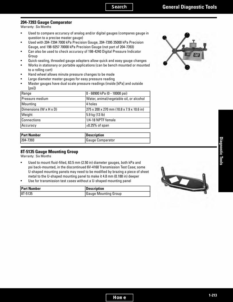
2584671
2584690
1-213
Diagnostic Tools
General Diagnostic Tools
204-7393 Gauge ComparatorWarranty: Six Months
• Used to compare accuracy of analog and/or digital gauges (compares gauge in question to a precise master gauge)
• Used with 204-7394 7000 kPa Precision Gauge, 204-7395 35000 kPa Precision Gauge, and 198-9257 70000 kPa Precision Gauge (not part of 204-7393)
• Can also be used to check accuracy of 198-4240 Digital Pressure Indicator Group
• Quick-sealing, threaded gauge adapters allow quick and easy gauge changes• Works in stationary or portable applications (can be bench mounted or mounted
to a rolling cart)• Hand wheel allows minute pressure changes to be made• Large diameter master gauges for easy pressure reading• Master gauges have dual scale pressure readings (inside [kPa] and outside
[psi])Range 0 - 68900 kPa (0 - 10000 psi)Pressure medium Water, animal/vegetable oil, or alcoholMounting 4 holesDimensions (W x H x D) 275 x 200 x 270 mm (10.8 x 7.9 x 10.6 in)Weight 5.9 kg (13 lb)Connections 1/4-18 NPTF femaleAccuracy ±0.25% of span
Part Number Description204-7393 Gauge Comparator
8T-5135 Gauge Mounting GroupWarranty: Six Months
• Usedtomountfluid-filled,63.5mm(2.50in)diametergauges,bothkPaandpsi back-mounted, in the discontinued 6V-4160 Transmission Test Case; some U-shapedmountingpanelsmayneedtobemodifiedbybrazingapieceofsheetmetal to the U-shaped mounting panel to make it 4.8 mm (0.188 in) deeper
• Use for transmission test cases without a U-shaped mounting panel
Part Number Description8T-5135 Gauge Mounting Group

2584703
2584725
1-214
Dia
gnos
tic T
ools
General Diagnostic Tools
6V-7830 TetragaugeWarranty: Six Months
• Functions as a general purpose pressure measuring device
• Capable of measuring hydraulic or air pressure from -100 to 40 000 kPa (-14.5 to +5800 psi)
• 2 lower pressure gauges are protected from over-pressurization by 2 sensor valves which shift and prevent pressure from increasing past a pre-set value which is less than the full-scale range of the gauges; the highest pressure gauge is not protected by a shutoff valve
• Background of the kPa scale is highlighted in yellow to indicate metric units
• Repair Kit: 8T-5324 Repair Kit
Item Part Number Description1 1U-5757 Hose Assembly2 8T-0862 Gauge, -100 to 500 kPa
(-14.5 to 72.5 psi)3 8T-0860 Gauge, 0 to 40,000 kPa (0 to
5,800 psi)
Item Part Number Description4 8T-0855 Gauge - Pressure5 6V-4144 Coupler Assembly (For
42000 kPa)6 4S-6399 Connector-- 6V-7830 Tetragauge
4C-5623 Smoke CandleSMCS Code: 7301-034, 7325-034Model: All ModelsWarranty: Six Months
• Easy,inexpensivewaytofindairleaksinvehiclecabsbypressurizingcabandwatchingforleaksidentifiedbyescapingwhite smoke
• Does not leave residue• Contains no explosive materials• Blends readily with air; stays in suspension for 10-15 minutes• Smoke is generated as a mist that contains a large amount of atmospheric moisture as opposed to solids being generated
as a by-product of burning. These smoke candles have a rating of 2100 total obscuring power (TOP), compared to 200 TOP forcrudeoil.TOPisthescientificmethodofdeterminingthequantityofsmokegeneratedbyagivenunitofsmokecomposi-tion.
Ordering InformationUS and Canadian dealers — This product is a direct shipped item from our supplier to anywhere in the US and Canada. Order this part number on the DTS (Dealer Terminal System) as a class 3A order. (There is no emergency charge for this product.)Do not order this product on a stock order. The system will not accept it. This direct shipped product is not stocked in Caterpillar® Parts Departments. The stock check procedure always shows “no stock” and therefore will reject the order.All dealers outside the US and Canada — Order as a class 3A order with your subsidiary parts department. (There is no emergency charge for this product.) After placement of your order you should notify your subsidiary parts department that this is a direct shipped item from the US. (Do not order this product on a stock order. The system will not accept it.) Your order will be direct shipped from the supplier through a freight forwarder in the US to your subsidiary parts department.
(Continued)

2584725
2584744
1-215
Diagnostic Tools
General Diagnostic Tools
4C-5623 Smoke Candle (Continued)SMCS Code: 7301-034, 7325-034Model: All ModelsWarranty: Six Months
Reference Material Safety Data Sheets (MSDS) for all chemical products are requiredbylaw.AllofCaterpillarMaterialSafetyDataSheetsareonfile at the Rocky Mountain Poison Center in Denver, Colorado. In addition, Caterpillar now has a dedicated “Safety Hotline” to the Center. This toll free number (1-800-458-5924) is staffed by trauma specialists 24 hours per day all year round and is available to US and Canadian dealers.Smoke duration 30 secondsSmoke color White to gray depending upon density and lightingVolume generated 113.3 m³ (4000 cu ft)Quantity 12 candles per box
Part Number Description4C-5623 Smoke Candle
9X-3075 Cable AssemblySMCS Code: 0781Model: Off-Highway TrucksWarranty: One Year
• Used to download information from TPMS (Truck Payload Measurement Sys-tem) to a users laptop computer
• Setup functions, diagnostics, and productivity reports are available using TPMS, this cable, and TPM software package (available separately)
• Truck cab connector: 5 pin MS• Computer connector: 9 pin serial port
Part Number Description9X-3075 Cable Assembly

2584762
2584784
2584809
1-216
Dia
gnos
tic T
ools
General Diagnostic Tools
127-9797 Cable, TPMS, VIMS, WLP to PCSMCS Code: 7494-038, 0779Model: All Off-Highway TrucksWarranty: One Year
• Replaces discontinued 9X-3393 Cable Group• Used to download data from off-highway trucks• Used with Truck Payload Measurement System (TPMS) software package and
IBM compatible personal computer• Cable connects to 5-pin circular connector on TMPS and 9-pin “D” connector
on computer• New cable allows data to be downloaded from ground level (eliminates need to
turn keyswitch inside cab)
Part Number Description127-9797 Cable, TPMS, VIMS, WLP to PC
Service/Repair Parts8C-6313 Connector8C-4797 Socket
9U-6386 Extension CableSMCS Code: 5050-082, 5050-036Model: 320, 330, and 325 Hydraulic ExcavatorsWarranty: One Year
• Used to extend reach of 7Y-5500 Control Group into cab — allows technician to adjust hydraulic system from inside cab
• Efficientandcosteffectivewaytodiagnosehydraulicsystemproblems• Length: 6 m (20 ft)
Part Number Description9U-6386 Extension Cable
Service/Repair Parts7N-8204 Socket Housing7N-8205 Plug Housing7N-7779 Socket Connector7N-7780 Pin Connector
218-3363 Breakout T-AdapterModel: Lexion CombineWarranty: One Year
• Usedtocheckvoltageatsolenoidwhileitisinuse(verifiesifsolenoidisnotworking or there is no power to solenoid)
• Fits all standard DIN 43650 type connectors• Connects between machine harness and solenoid
Part Number Description218-3363 Breakout T-Adapter
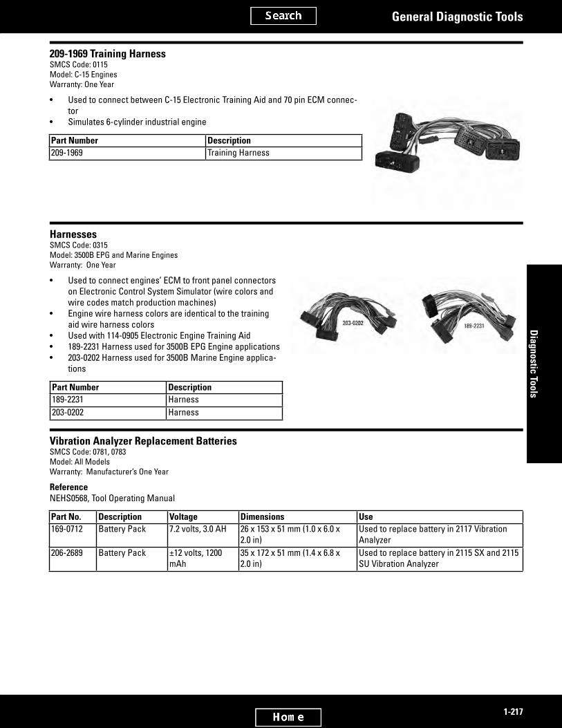
2584824
2584841
2584857
1-217
Diagnostic Tools
General Diagnostic Tools
209-1969 Training HarnessSMCS Code: 0115Model: C-15 EnginesWarranty: One Year
• Used to connect between C-15 Electronic Training Aid and 70 pin ECM connec-tor
• Simulates 6-cylinder industrial engine
Part Number Description209-1969 Training Harness
HarnessesSMCS Code: 0315Model: 3500B EPG and Marine EnginesWarranty: One Year
• Used to connect engines’ ECM to front panel connectors on Electronic Control System Simulator (wire colors and wire codes match production machines)
• Engine wire harness colors are identical to the training aid wire harness colors
• Used with 114-0905 Electronic Engine Training Aid• 189-2231 Harness used for 3500B EPG Engine applications• 203-0202 Harness used for 3500B Marine Engine applica-
tions
Part Number Description189-2231 Harness203-0202 Harness
Vibration Analyzer Replacement BatteriesSMCS Code: 0781, 0783Model: All ModelsWarranty: Manufacturer’s One Year
ReferenceNEHS0568, Tool Operating Manual
Part No. Description Voltage Dimensions Use169-0712 Battery Pack 7.2 volts, 3.0 AH 26 x 153 x 51 mm (1.0 x 6.0 x
2.0 in)Used to replace battery in 2117 Vibration Analyzer
206-2689 Battery Pack ±12 volts, 1200 mAh
35 x 172 x 51 mm (1.4 x 6.8 x 2.0 in)
Used to replace battery in 2115 SX and 2115 SU Vibration Analyzer

2584874
2584901
1-218
Dia
gnos
tic T
ools
General Diagnostic Tools
4C-9021 Torsional Vibration Measuring GroupDiscontinued — Service/Repair Parts Available
• Discontinued but with some service/repair parts still availableReferencesNEHS0558, Special Instruction,4C-9024 Battery GroupItem Description11 NEHS0562 Tool Operating Manual NEEG2471 Decal NEEG2503 Decal
Item Part Number Description1 8D-8113 Fuse1 4C-9024 Battery Pack Group (12 V)2 4C-9023 Volts Adapter3 4C-6918 Photo Head Pickup NEEG2455 Decal (not
shown)4 4C-6917 Photo Head Adapter Assembly4 8D-6894 Washer4 4C-6916 Magnetic Base Group4 2S-6251 Machine Screw5 4C-6919 Retro-ReflectiveTape,25mm(1in)x2.5
m (100 in) long6 6V-2198 Extension Cable (X8)7 4C-6921 Adapter Cable Assembly (photo head to
analyzer)8 4C-9028 Adapter Cable Assembly (sure seal-BNC)9 5N-9292 Magnetic Pickup10 4C-3036 Cable Assembly (10 ft BNC-BNC)-- 4C-9021 Torsional Vibration Measuring Group
Not shown-- 4C-9658 1 Case - Protective-- 7T-0037 Fuse
1 Fold-down handle
Accessories for 4C-3030 Vibration Analyzer GroupSMCS Code: 0781, 0783Model: All ModelsWarranty: One Year
4C-3032 Accelerometer• Useful for higher frequency measurements where acceleration units are needed• Responseisflatbetween6and6000Hz(±5%,3-10000Hz).Model Wilcoxon Research Model 762SWeight 80 g (0.18 lb)Dimensions 43.2 x 21.6 mm (1.7 x 0.85 in) diameter)Sensitivity 10 mV/GFrequency response ±5% 3.0-10000 Hz, ±10% 2.0-12000 Hz, ±3 dB 1.0-15000 HzTemperature range -50° to 120° CAttachment 1/4-28 thd
(Continued)

2584901
2584917
2584931
2744552
1-219
Diagnostic Tools
General Diagnostic Tools
Accessories for 4C-3030 Vibration Analyzer Group (Continued)SMCS Code: 0781, 0783Model: All ModelsWarranty: One Year
Part Number Description4C-3030 Vibration Analyzer Group4C-3032 Accelerometer
163-0097 Spare BatterySMCS Code: 0785Warranty: Six Months
• For discontinued 163-0096 Process Calibrator
Part Number Description163-0097 Battery
Fluid Sampling Valves and Quick Connect CouplersSMCS Code: 5050-036Warranty: One Year
• Used to quickly take oil test samples (S·O·S) or make diagnostic connections• Used with 169-8373 Bottle Group (oil sampling)• Easyconnectionbetweencouplerandsamplingvalveforcontinuousoilflow• Designedspecificallyforusewithportableparticleanalyzer• Specificgroupsdesignedtoworktogetherwithoutleaksordamagetosamplingvalvesorcoupler
Single-Purpose Sampling Valves and Coupler• Low-pressure,single-purposesamplingvalvesandcouplerusedtosamplefluid
only• Do not use with 183-7264, 183-8652, and 229-5465 Sampling Valves
or 210-5530 Quick Coupler• Quickcouplerhasblackoxidesleeveforeasyidentification
Item Part Number Thread DescriptionOperating Size
Burst Pressure Max. Pressure Seal Temperature Seal Material
Low-Pressure, Single-Purpose Quick Coupler and Sampling Valves1 243-3133 Quick Coupler 3/4 -18 NPTF 3500 kPa
(500 psi)14,000 kPa (2,000 psi)
107° C ( 225° F) BunA-N
2 8C-3345 Sampling Valve M10 x 1 3500 kPa (500 psi)
14,000 kPa (2,000 psi)
121° C ( 250° F) Viton
3 8C-3446 Sampling Valve 7/16 - 20 3500 kPa (500 psi)
14,000 kPa (2,000 psi)
121° C ( 250° F) Viton
4 7X-3387 Sampling Valve 1/4 - 18 NPTF 3500 kPa (500 psi)
14,000 kPa (2,000 psi)
121° C ( 250° F) Viton

2744582
2584973
1-220
Dia
gnos
tic T
ools
General Diagnostic Tools
Dual-Purpose Sampling Valves and Coupler• High-pressure,dual-purposevalvesandcouplerusedtosamplefluidandfor
diagnostic purposes• Do not use with 8C-3345, 8C-3446, and 7X-3387 Sampling Valves or 243-3133
Quick Coupler• Dual-purposesamplingvalvesareflowratedat3L(0.79gal)aminuteindiag-
nostic applicationsNOTICEUsing discontinued 170-8505 Quick Coupler will cause damage to 183-7264, 183-8652, and 229-5465 Sampling Valves.
Item Part Number Description Thread SizeOperating Pressure Max. Pressure Seal Temperature Seal Material
High-Pressure, Dual-Purpose Quick Coupler and Sampling Valves1 210-5530 Quick Coupler 1/4 - 18 NPTF 41,350 kPa
(6,000 psi)-- 104° C ( 220° F) BunA-N
2 183-7264 Sampling Valve
9/16 - 18-2A 41,350 kPa (6,000 psi)
10,300 kPa (1,500 psi) -- Viton
3 183-8652 Sampling Valve
9/16 - 18 41,350 kPa (6,000 psi)
10,300 kPa (1,500 psi) -- Viton
4 229-5465 Sampling Valve
7/16 - 20 41,350 kPa (6,000 psi)
10,300 kPa (1,500 psi) -- Viton
170-8500 S40 Particle Analyzer GroupSMCS Code: 0784, 5050-082Warranty: Manufacturer’s One Year
European Union compliant, CE marked• Used to analyze particle contamination on pressurized and non-pressurized hydraulic
systems• Portable self-contained system uses red laser sensor technology to count and size par-
ticlesinfluids(samesensortechnologyasparticleanalyzersusedinS·O·SlabandotherCaterpillar® factory applications)
• Performsfluidanalysisin90seconds• Internal battery pack capable of performing 60 tests per charge• Self-contained digital display and printer shows test results• Equipped with keypad and graphical, back-lit LCD (Liquid Crystal Display) with resistive
touch screenRepair InformationThe unit is warranted by the manufacturer for 1 year from date of receipt. If the unit needs servicing, contact one of the following manufacturer’s repair facilities:C & J International Inc.6721 E. 106th Street Tulsa, OK 74133, USA Tel: 0 01 91 82 99 40 19 Fax: 0 01 91 82 99 74 10Sintech Scientific (SEA) Pet Ltd.No. 196 Pandan Loop # 02-18 Pantech Industrial Complex Singapore 128384 Tel: 0 06 57 79 00 07 Fax: 0 06 58 72 23 92
(Continued)

2584973
1-221
Diagnostic Tools
General Diagnostic Tools
170-8500 S40 Particle Analyzer Group (Continued)SMCS Code: 0784, 5050-082Warranty: Manufacturer’s One Year
PAMAS GmbH Dieselstrabe 10 D-71277 Rutesheim Postfach 162 Germany Tel: + 49 7152 9 96 30 Fax: + 49 7152 5 48 62ReferenceNEHS0799, Tool Operating ManualOperating voltagesInternal battery 100 - 240 VAC 50/60 HzExternal battery 12 - 24 VDC Weight 9 kg (20 lb)Measurements 300 x 140 x 300 mm (11.8 x 5.5 x 11.8 in)Ambient temperature 5° to 40° C (40° to 104° F)Relative humidity Maximum 70%Size range 4-30mm(certifiedISO-11171)Maximum viscosity 300 cSt
Part Number Description170-8500 S40 Particle Analyzer Group
Service/Repair Parts184-7679 Paper - Roll131-5047 Cable - Power, 110 VAC (USA Plug)6V-4144 Coupler Assembly (For 42000 kPa)
Part Number DescriptionService/Repair Parts (Continued)
9U-6794 Adapter170-8506 Hose Assembly188-0639 Hose Assembly - Low-Pressure
383-4255 Contamination MonitorModel Usage: AllWarranty: Manufacturer’s
European Union compliant, CE marked• Portable service unit for the temporary measurement of particulate contamina-
tion,watersaturationandfluidtemperatureinhydraulicsystems• Integrated pump for measurement in pressureless reservoirs• Operation with 24 VDC adaptor included• Replaces 293-8413 Contamination Monitor
(Continued)

2901273
2584999
1-222
Dia
gnos
tic T
ools
General Diagnostic Tools
383-4255 Contamination Monitor (Continued)Model Usage: AllWarranty: Manufacturer’s
SpecificationsDisplay LED, 6/4/4 digits in 17 segment formatMeasuring Range Saturation level 0 to 100% Temperature
-25° to 100° C (-13° to +212° F)Accuracy + /- 1/2 ISO class in the calibrated range /
≤ ± 2% full scale maximumAmbient Temperature Range 0 to 45° C (32 to 113° F)Storage Temperature Range -40 to 80° C (-40 to 176° F)IP Class IP50 in operation IP67 closedWeight 13 kg (29 lb)Pressure Maximum 345 bar/5000 psiFluid Temperature Range 0 to 70° C (32 to 158° F)Power Supply Voltage 24 V DC ± 20%, residual ripple< 10%Maximum Power Current Consumption 100 Watt / 4AInterface Plug connection, 5-pole, male (M12 x 1)
Part Number Description383-4255 Contamination Monitor
293-8413 HYDAC Contamination Monitor GroupEssential ToolSMCS Code: 0784, 5050-82Warranty: One Year
European Union compliant, CE marked• Used to monitor hydraulic and lubrication oil cleanliness• Analyzes particle contamination on pressurized and non-pressurized systems• Direct connection to low or medium pressure line of hydraulic system or ma-
chine for continuous monitoring• Integrated pump used to take samples on non-pressurized reservoirs• Particulate contamination detection by optical measurement cell• Single INLET and OUTLET connections• OUTLET requires use of non-pressurized reservoir (not supplied)• Easy-to-see LED displays ISO, SAE, FLOW, DRIVE, and TEMP readings• Durable sealed keypad operation• Automatic measurement and display of cleanliness ratings as ISO Code
(4406:1999) or SAE Code AS4059 (D)• Includes power cable, low and high pressure inlet hoses, outlet hose, battery
clips adapter for 24 VDC, and integrated caseRepair InformationThis unit is warranted by the manufacturer for one year from date of receipt. If the unit needs servicing, contact the manufacturer’s repair facility.GermanyHYDC Servicecenter Rehgrabenstrasse, Werk 7 661225 Saarbrucken Germany Tel: +49 (0) 6897 509 01
(Continued)

2584999
1-223
Diagnostic Tools
General Diagnostic Tools
293-8413 HYDAC Contamination Monitor Group (Continued)Essential ToolSMCS Code: 0784, 5050-82Warranty: One Year
USA HYDAC Technology Corporation Service Department 2280 City Line Road Bethlehem, PA 18017 Phone: (610) 266-0100ReferenceNEHS0978, Tool Operating Manual, 293-8413 HYDAC Contamination MonitorOperating voltage 24 VDC ± 20%, ripple £ 10%Weight Approximately 9 kg (20 lb)Dimensions (with case) 340 x 220 x 300 mm (13.4 x 8.7 x 11.8 in)Ambient temperature range 0° to 45° C (32° to 113° F)Relative humidity Maximum 90%Oil temperature range 0° to 70° C (32° to 158° F)Cleanliness class > 4μm(c) > 6μm(c) > 14μm(c) > 21μm(c)Viscosity range 10 - 350 mm²/s (46 - 1622 Sus)Inlet pressure range 0 - 45 bar (0 - 650 psi)Pumpflowrate 30 - 300 ml/min (1.0 - 10.1 oz/min)
Part Number Description293-8413 HYDAC Contamination Monitor Group
Service/Repair Parts293-8414 Power Cable (291-1321 Fuse, 8 amp)293-8415 Low Pressure Inlet Hose, 0.3 m (11.81 in)293-8416 High Pressure Inlet Hose for Test Point 1620, 2 m (78.74 in)293-8417 Outlet/Return Hose, 1 m (39.37 in)293-8418 Battery Clips Adapter for connecting to 24 VDC
Not Shown289-2920 AC/DC Power Supply Adapter289-2921 DC/DC Power Supply Adapter, 12 to 24 VDC
285-3850 USB A/B CableWarranty: One Year
• Used to connect USB devices to a personal computer• Nominal length: 1.8 m (70 in)• USB 2.0 compliant cable
Part Number Description285-3850 USB A/B Cable

2585037
2585052
2745117
1-224
Dia
gnos
tic T
ools
General Diagnostic Tools
243-3130 Contamination Monitor GroupDiscontinued — Service/Repair Parts Available
Repair InformationThe unit is warranted by the manufacturer for 1 year from date of receipt. If the unit needs servicing, contact the manufacturer’s repair facility:PAMAS-USA 6721 E. 106th Street Tulsa, OK 74133, USA Phone: 918-299-4019 Fax: 918-299-7410
Part Number Description243-3130 Contamination Monitor Group
Service/Repair Parts243-3131 Battery Supply Power Cable with Alliga-
tor Clips243-3132 AC Adapter Power Supply243-3144 RS232 Communications Cable188-0639 Hose Assembly - Low-Pressure
Fitting GroupsSMCS Code: 0783, 0784Warranty: One Year
Item Part Number Description Qty.— 220-8608 Fitting Group —— 220-8607 Fitting Group —
Service Kits (Sold Separately)1 220-8609 Tube Insert Kit 102 220-8610 Tube Nut Kit 103 220-8611 Tube Ring Kit 10
220-8607 Fitting Group• Used to connect a particle analyzer to a low pressure source, quick
disconnectfitting,or210-5530S·O·Squickdisconnectfitting• Used with 6 mm plastic tubing• 1/4 inch NPT threaded end• Comes with 220-8604 Brass
Tube Insert for plastic tubing
220-8607 Fitting GroupPart Number 1 Description220-8602 Tube Fitting220-8604 Brass Tube Fitting
1 Not Serviced

2745130
2585086
1-225
Diagnostic Tools
General Diagnostic Tools
220-8608 Fitting Group• Replaceshighpressureinput/lowpressureoutputfittings
on170-8500ParticleAnalyzerwithlowpressurefittings• Used with 6 mm plastic tubing• Used for pressures between 0 and 689 kPa (0 and 100 psi)• EliminatesflowrestrictionforSAE50andSAE60highviscosity
fluidsduringlowpressuresampling• Connects low pressure tubing to 170-8500 Particle Analyzer
fordirectfluidflowintoacatchcan or bottle
• 1/4 inch BSPP threaded end• Comes with 220-8604 Brass Tube Insert
for plastic tubing
220-8608 Fitting GroupPart Number 1 Description220-8603 Tube Fitting220-8604 Brass Tube Fitting
1 Not Serviced
202-2301 Portable Contamination Instructional KitWarranty: Six Months
• Usedtoestimateamountandtypeofsolidcontaminationinhydraulicfluidorlubricationoil(cannot determine exact particle counts)
• Conducton-the-spotvisualfieldevaluationsofsystemfluidcontamination• Canbeusedbytrainedtechnicianstocompareactualpatches(25mlfluidvolume)to
examples shown in NEHS0729 to generally classify amount and type of contamination in a fluidsample
ReferenceNEHS0729, Portable Contamination Instructional Kit (The examples shown in this brochure are typical of the type of contamination found using the portable contamination instructional kit. The examples are shown for reference only. Instructions on obtaining, preparing and viewing samples are also provided in this brochure.)Item Description2 500 ml (16 oz) LDPE Wash Bottle with 28 mm
(1.10 in) Cap9 Grease Pencil10 Spray Stem for Bottle12 Microscope13 Penlight (Included with microscope)
Item Part Number Description1 202-2267 Dish Kit3 6V-9449 Carrying Case 1
4 202-2266 Funnel5 1U-5718 Vacuum Pump6 4C-6605 Tweezers7 231-9405 Patch Group
Item Part Number Description8 169-7372 Bottle As (4)11 1U-9533 AA Batteries for Light (2)-- 202-2301 Portable Contamination Instructional
KitNot Shown
-- 1U-5719 Seal Kit for 1U-5718 Vacuum Pump
1 Replacement case without foam

2585109
2585132
2585139
1-226
Dia
gnos
tic T
ools
General Diagnostic Tools
8C-8456 Sealed CapWarranty: Six Months
• Used to seal the valved and non-valved nipples listed below (nipples are used on machines, tool groups, and dealer shop equipment.)
• Heavy-duty, pressure-tight cap that provides both positive sealing and added protection for the nipples
Operating pressure 42,000 kPa (6,100 psi)Minimum burst pressure 168,000 kPa (24,000 psi)Operating temperature -34° to 107° C (-29° to 225° F)Seal material High Temp. (BunA-N®)
Part No. Description Color8C-8456 Sealed Cap —
Adaptable to these Pressure Diagnostic Quick Disconnect Nipples
6V-3965 Nipple - STR 9/16 in - 18 thd SAE external (for #6 Port) BunA-N® Seal
Zinc chromate
6V-3966 Nipple As 1/4 in-NPTF external thd BunA-N® Seal
Zinc chromate
6V-3989 Nipple - unvalved 1/4 in-NPTF internal thd non-valved
Zinc chromate
6V-4142 Nipple - unvalved 1/4 in-NPTF internal thd non-valved
Zinc chromate
Part No. Description ColorAdaptable to these Pressure Diagnostic Quick Disconnect
Nipples (Continued)6V-4433 Nipple As - valved 9/16 in-18 thd
external (for #6 Port) Viton SealGreen chromate
6V-7691 Nipple As - valved 1/4 in-NPTF external thd Ethylene Propylene Seal
Red chromate
8T-3613 Nipple As - valved 1/8 in-NPTF external thd BunA-N® Seal
Zinc chromate
8T-3614 Nipple As - valved 1/8 in - NPTF external thd. Ethylene Propylene Seal
Red chromate
Fluid Sampling SuppliesWeofferacompleteassortmentoffluidextractiontoolstoservicepressurizedvehiclecompartmentssuchasengine,transmis-sion,andhydraulicsystems,aswellasnon-pressurizedvehiclecompartmentssuchasfinaldrives,differential,transfercase,and axle housings. Get extra protection and maximum performance by using Cat®fluids,filters,andregularoilanalysisthroughscheduled oil sampling (S·O·S).
Fluid Sampling Extraction Tools for Pressurized CompartmentsWarranty: Six Months
• Valvelocationsprovideoilsampleconfidenceandcontinuity—comparativedataofpressurizedoilsamplesismorereli-ablebecausethesampleistakenfromacontinuousflowofoilataknownlocation
• Probeisprovidedthatallowsthevalvetobequicklyflushedpriortotakingtheoilsample• Sample bottle group is packaged, and sealed in a plastic bag to insure cleanliness• Pressurized oil sampling is a fast, economical and clean method of obtaining oil samples from pressurized system.• Better represents oil condition because the oil is continually mixed and circulated• 10 to 20 times faster than sampling oil from non-pressurized systems• Mailing container is available so the oil sample can be conveniently mailed to the testing laboratory169-8373 Bottle Group (Package Qty. — 300)This bottle group is sealed in a plastic bag with sampling instructions included. The bottle group is ready to use when it is removed from the bag after the valve has been purged and the sample is ready to be taken. The bottle included in this group (169-7372) has the capacity to provide a 114 g (4 oz) sample. The 169-7372 can also be ordered by itself, 200 per case.
(Continued)

2585139
1-227
Diagnostic Tools
General Diagnostic Tools
Fluid Sampling Extraction Tools for Pressurized Compartments (Continued)Warranty: Six Months
After the sample is obtained, the probe and tube are removed from the bottle cap and holder, and discarded, and the cap-cover seals the bottle. Labels for identifying the sample (obtained locally) can then be attached tothebottleforidentificationpurposes.The4C-4600mailtubeisavailable to send the oil sample to the laboratory. The laboratory also provides the mailing label.177-9343 Probe and Cap Group (Package Qty. — 500)The probe and cap group provides the same probe and cap that are used in the 169-8373 Bottle Group, however, without the bottle. This group is also sealed in a plastic bag with sampling instructions included. This group allowsthedealertheflexibilitytouseotherbottlessuchasthesmaller 71 g (2 1/2 oz) 169-7373 bottle assembly (which must be ordered separately). (The cap requires that the bottles have a 38 M thread.)169-7373 Bottle Assembly (Package Qty. — 200)This smaller bottle assembly (169-7373) can be used with the 177-9343 Probe and Cap Group and reduces mailing expense by approximately one-half for dealers whose oil sample labs can provide effective full service analysis with 71 g (2 1/2 oz) or less of oil. These bottles can be used for engine samples since particle count is not used for engine samples. This bottle can also be used with the 1U-5718 Vacuum Pump used for non-pressurized oil sampling.8T-9208 Probe Assembly (Package Qty. — 1)The8T-9208ProbeAssemblycanbeattachedtoa6.35mm(1⁄4in)IDrubber hose (6K-0713 Hose — 228.6 mm (9 in) long or any desired length cut from bulk 5P-6442 Hose or equivalent 100R6 type high temperature — low pressure hose). The 8T-9208 Probe and hose connected to a locally obtainedwastecontainerprovideamethodtopurgeorflushthe8C-3446, 8C-3345, or 7X-3387 sample valves prior to obtaining the desired oil sample using either the 169-8373 Bottle Group or 177-9343 Probe and Cap Group with the desired bottle. Approximately 14.8 cm³ to 29.6 cm³ (1/2 to 1 ounce) ofexpelledfluidpurgesthevalves.Pressurized systems on many Cat® products are factory equipped with sampling valves to quickly extract oil samples with the above tools. Special InstructionSEHS9043detailsretrofittingsomeearliermodelswithoil sampling valves, as well as pointing out the respective valve locations on models currently factory equipped with the oil sample valves
Item Part Number Description1 169-8373 Bottle Group, 300 per box2 162-8873 Probe, Holder3 177-9343 Probe and Cap Group, 500 per box4 4C-4600 Mailer Container — reusable Tube — 30.5 m (100 ft) rolls
(Continued)

2585139
2747458
1-228
Dia
gnos
tic T
ools
General Diagnostic Tools
Fluid Sampling Extraction Tools for Pressurized Compartments (Continued)Warranty: Six Months
Item Part Number Description5 1U-8757 6.35 mm OD x 30.5 m rolls (1/4 in OD x 100 ft) 5 rolls per box6 4C-4056 7.9 mm OD x 30.5 m rolls (5/16 in OD x 100 ft) 5 rolls per box, not
pictured7 169-7373 Clear Bottle, 71 g (2.5 oz), 200 per box8 169-7372 Clear Bottle, 114 g (4 oz), 200 per box9 1U-5718 Vacuum Pump9 1U-5719 Seal Kit for 1U-5718 Pump (not pictured)10 8T-9208 Purging Probe 1
11 1U-7648 Tube Cutter11 1U-8589 Replacement Blades (not pictured)12 8C-8456 Sealed Cap13 8C-3446 Oil Sampling Valve (7/16 in-20 — ext. thd)13 3J-7354 Seal - O-ring - STOR for 8C-3446 (not pictured)14 7X-3387 S·O·S Sampling Valve15 8C-3345 Oil Sampling Valve (M10 x 1 — ext thd)15 8T-7876 O-ring Seal for 8C-3345 (not pictured)16 8C-3445 Dust Cap (Engine)16 8C-3447 Dust Cap (Transmission) (not pictured)16 8C-3451 Dust Cap (not pictured)16 6V-0852 Dust Cap (Blank) (not pictured)
Not Shown - Tube, 2.1 m (7 ft) pieces-- 4C-4057 7.9 mm OD x 2.1 m (5/16 in OD x 7 ft), 240 pieces per box-- 4C-4055 6.35 mm OD x 2.1 m (1/4 in OD x 7 ft), 250 pieces per box
1 Warranty: Manufacturer’s, 30-Day
Fluid Sampling Valves, Fittings and AdaptersThefollowingvalves,fittingsandadaptersarerequiredorarecommonlyusedforretrofittingthesamplingvalvestopressurizedsystems:
Part Number 1 DescriptionOil Sampling Valves and O-ring Seals (Sold Separately)
8C-3446 Oil Sampling Valve (7/16 in-20 — ext. thd)3J-7354 O-ring Seal for 8C-34468C-3345 Oil Sampling Valve (Mid X1 ext. thd)8T-7876 O-ring Seal Form 8C-33457X-3387 Oil Sampling Valve (1/4 in-18 NPTF ext. thd)
Protective Dust Caps for Oil Sampling Valves (These are rubber caps with embossed symbols to indicate system being sampled.)
8C-3445 Dust Cap (Engine)8C-3447 Dust Cap (Transmission)8C-3451 Dust Cap (Hydraulic)6V-0852 Dust Cap (Blank)8C-8456 Sealed Cap
Miscellaneous fittings and adapters commonly used for oil sampling valve retrofit installations (Sold Separately) 1
3B-7722 Bushing-Pipe-Reducing 3/8 in-18 NPTF to 1/4 in-18 NPTF8C-6427 Adapter, 1/4 in-18 NPTF external to 7/16 in-20 SAE internal6V-7529 Adapter, 1/8 in-27 NPTF external to 7/16 in-20 SAE internal
(Continued)

2747458
2885872
2585215
1-229
Diagnostic Tools
General Diagnostic Tools
Fluid Sampling Valves, Fittings and Adapters (Continued)
Part Number 1 DescriptionMiscellaneous fittings and adapters commonly used for oil sampling valve retrofit installations (Sold Separately) (Continued) 1
7J-8611 Elbow-90°-Pipe 1/4 in-18 NPTF5P-9617 Adapter Reducer, 9/16 in-18 SAE external to 7/16 in-20 SAE internal3J-1907 O-ring Seal for 5P-9617 Adapter3J-5390 Plug - NPTF (Ext Hex) 3/8 in-18 NPTF external to 1/8 in-27 NPTF internal9T-6865 Adapter Plug, 5/8 in-12 SAE external to 7/16 in-20 SAE internal2S-4078 O-ring Seal for 9T-6865 Adapter Plug5P-3501 Adapter, 9/16 in-18 SAE external to 1/4 in-18 NPTF internal3L-6521 Adapter Tee, 1/4 in-18 NPT (2 internal and 1 external)6V-3966 Pressure Test Valve, 1/4 in-18 NPTF external7M-8489 Adapter Assembly, 90° elbow 9/16 in-18 SAE external to 1/4 in-18 internal5P-3413 Pipe Sealant, 47.25 g (1 2/3 oz) tube
1 All part numbers in the table have a six month warranty
8C-8456 Sealed CapThe 8C-8456 Sealed Cap can be applied to the valves with the valve dust cap retention ring left in place. This cap enables the user to quickly seal a leaking valve and prevents the need to immediately deadline (or stop) the machine or compartment.Theleakingvalvecanthenberepaired(flushed)orreplaced during the scheduled maintenance period.Someretrofitapplicationsofthevariousvalvesmayrequirethe8C-8456Sealed Cap to provide maximum protection for both sealing and environmental contamination, such a brake and hydraulic system exposed to severe elements. This cap serves ONLY as a temporary solution to a leaking sampling valve.
Fluid Sampling Extraction Tools for Non-Pressurized CompartmentsWarranty: Six Months
Fluidsamplingextractiontoolsareusedtoobtainfluidsamplesfromnon-pressurized vehiclecompartmentssuchasfinaldrives,differentialcompartments,transfercases, axle housings, etc.The 1U-5718 Vacuum Pump is capable of pulling 7.62 mm (25 in) Mercury (vacuum). The pump is compact and accepts the 169-7372, 114 g (4 oz), and 169-7373 Bottle Assembly, 71 g (2.5 oz), bottles, or any 38 M threaded plastic bottle, and 6.35 mm (1/4 in) OD and/or 7.9 mm (5/16 in) OD plastic tube.The 1U-5719 Kit provides replacement seals for the vacuum pump.The169-7372Bottlehas114g(4oz)capacity.Thebottleismarkedshowingfluidfill rangeat3/4capacity.Thefillrangeprovidesaremindertonotoverfillthebottle. Partiallyfillingthebottlesatisfiesbothmailingandlabrequirements.Fullbottles expand because of temperature changes that can possibly rupture within the mailing container.Thepartiallyfilledbottlealsoallowsthelabtoshakethefluidsampleprior toextractingfluidfortesting.Labelsidentifyingthefluidareobtainedlocally.Thelabel is processed locally and attached to the sample bottle.The 169-7373 Bottle is the same as the 169-7372 bottle except the capacity is 71 g (2.5 oz) rather than 114 g (4 oz). Both are clear high performance plastic rated at 91° C (195° F).The1U-8757Tubingconsistsoffive30.5m(100ft)rollsof6.35mm(1/4inch)ODplastic tubing. Random lengths of tubing can be easily dispensed from the tubing package. Thetubingconnectsthevacuumpumptothefluidinthecompartment.Thetubingis discarded after each sample is extracted.
(Continued)

2585215
1-230
Dia
gnos
tic T
ools
General Diagnostic Tools
Fluid Sampling Extraction Tools for Non-Pressurized Compartments (Continued)Warranty: Six Months
The4C-4056Tubingconsistsoffive30.5m(100ft)rollsof7.9mm(5/16inch)ODplastic tubing. Again, random lengths of tubing can be easily dispensed from the tubing package. This tubing permits extraction of heavier oils when using the vacuum pump.Both tubing sizes are also available in pre-cut 2.1 m (7 ft) lengths that are packaged 250 pieces per box. This eliminates cutting the tube for each sample.The 4C-4055 Tubing contains 250 pieces of 6.35 mm (1/4 in) OD tubing each 2.1 m (7 ft) long.The 1U-7648 Tube cutter is a convenient tool that easily cuts the desirable length of either 6.35 mm (1/4 in) or 7.9 mm (5/16 in) plastic tubing. The cutter can cut the tubing at 90° or at a bias. The 1U-8589 blades are available as replacement blades for the cutter.The following summarizes various sampling tools available through the Caterpillar® Parts Distribution System:
Part Number Description4C-4056 Tube, 7.9 mm (5/16 in) OD by 30.5 m (100 ft)
length (5 rolls per box)4C-4057 Tube, 7.9 mm (5/16 in) OD by 2.1 m (7 ft) length
(250 per box)4C-4055 Tube, 6.35 mm (1/4 in) OD by 2.1 m (7 ft) length
(250 per box)177-9343 Probe and Cap Group8C-3345 Oil Sampling Valve8C-3446 Oil Sampling Valve8C-3445 Dust Cap (Engine)8C-3447 Dust Cap (Transmission)8C-3451 Dust Cap (Hydraulic)8C-8456 Sealed Cap3J-7354 O-ring Seal for 8C-3446 Valve
Part Number Description8T-7876 O-ring Seal for 8C-3345 Valve169-8373 Bottle Group8T-9208 Purging Probe, brass1U-5718 Vacuum Pump1U-5719 Seal Kit for 1U-5718 Vacuum Pump169-7372 Bottle, 114 g (4 oz)169-7373 Bottle, 71 g (2 1/2 oz)4C-4600 Mail Tube1U-7648 Tube Cutter1U-8589 Replacement Blades1U-8757 Tube, 6.35 mm (1/4 in) OD by 30.5 m (100 ft)
length (5 rolls per box)6V-0852 Dust Cap (Blank)7X-3387 Oil Sampling Valve