Embed Size (px)
Citation preview

Cary 50
Hardware
Operation manual
Installation Category IPollution Degree 2Safety Class 3 (EN61010-1)
Publication No. 85 10159600June 1999
Cary 50
Publication date: 06/99ii
Varian officesVarian has offices in most countries. The major offices for opticalspectroscopy products are listed below:
Varian Australia Pty Ltd (Manufacturing site)
679 Springvale Road
Mulgrave, Victoria 3170
Australia
International telephone: + 61 3 9560 7133
International fax: + 61 3 9560 7950
Varian Instruments2700 Mitchell Dr.Walnut Creek, CA 94598 USAPhone:1 800 926 3000International telephone: +1.925.939.2400International fax:+1.925.945.2102
Varian Chrompack Benelux Analytical InstrumentsBoerhaaveplein 7, 4624 VT Bergen op ZoomPostbus 250, 4600 AG Bergen op Zoom, NetherlandsInternational telephone: +31 0164 282800International fax: +31 0164 282828
Internet
The Varian Internet home page can be found at:
http://www.varianinc.comVarian Australia Pty Ltd is the owner of copyright on this documentand any associated software. Under law, the written permission ofVarian Australia Pty Ltd must be obtained before either thedocumentation or the software is copied, reproduced, translated orconverted to electronic or other machine-readable form, in whole, or inpart.
First published 1997 in Australia. Updated Feb, June 1999. Commentsabout this manual should be directed to the MarketingCommunications Manager, Varian Australia at the address above orby Email to [email protected].
Varian Australia is ISO9001 certified.
© 1997 Varian Australia Pty Ltd (A.C.N. 004 559 540)
All rights reserved

Cary 50
Publication date: 06/99 iii
Declaration of ConformityWe hereby Declare that the equipment
listed below complies with the requirements of:-The Low Voltage Directive 73/23/EEC (93/68/EEC)
The EMC Directive 89/336/EEC (92/31/EEC and 93/68/EEC)
Applicable StandardsLVD BS EN 61010-1:1993EMC BS EN55011:1991 BS EN 50081-1:1992 BS EN 50082-1:1992
IEC 801-2:1991 IEC 801-3:1984 IEC 801-4:1988
Equipment Model Number Cary 50 Series
Responsible Person in the EU.Print Name: W. David Lowe Company Name Varian Ltd
Address 28 Manor RoadSigned: Walton-on-ThamesPosition: Managing Director Surrey KT12 2QF UKDate: 25-08-97 Telephone (1932) 898 000
Facsimile (1932) 228 769Manufacturer
Print Name: Gregory Davis Company Name Varian Australia Pty LtdAddress 679 Springvale Road
Signed: Mulgrave VIC 3170Position: Managing Director AUSTRALIADate: 25-08-97 Telephone (03) 9560 7133
Facsimile (03) 9560 7950
Publication number 85 101595 00 08/97

Cary 50
Publication date: 06/99iv
This page is intentionally left blank

Cary 50
Publication date: 06/99 v
Table of Contents
Safety practices and hazards vii
1 Introduction 1-1
1.1 Installation requirements 1-1
1.2 Cary documentation 1-1
1.3 Specifications 1-21.3.1 Environmental 1-21.3.2 Personal computer 1-31.3.3 Connections 1-31.3.4 Weights and dimensions 1-3
2 Installation 2-1
2.1 Cell holder 2-22.1.1 Installation 2-32.1.2 Alignment 2-32.1.3 Other sample holders 2-4
3 Maintenance 3-1
3.1 Cleaning 3-1
3.2 Lamp module 3-23.2.1 Lamp module replacement 3-23.2.2 Aligning the source mirror 3-5
4 Troubleshooting 4-1
4.1 Installing a Cary 50 under Windows NT 4-14.1.1 Windows NT service or driver failure 4-24.1.2 Access denied 4-54.1.3 Fcary service failed to start 4-64.1.4 There is no green light indicating that the Cary 50 is
powered. 4-74.1.5 Start button replaced with Connect button 4-74.1.6 Hard disk power supply connection 4-84.1.7 The Absorbance is 10 Abs and fluctates wildly
during a scan. 4-94.1.8 Windows 95/98 Input/Output hardware conflict 4-94.1.9 No free Interrupt request 4-10
Cary 50
Publication date: 06/99vi
4.2 Instrument performance testing 4-11
4.3 Un-installing the Cary 50 driver 4-12
4.4 Un-installing the WinUV software 4-13
5 Spare parts 5-1

Cary 50
Publication date: 06/99 vii
Safety practices andhazards
Your Varian Cary instrument and accessories have been carefullydesigned so that when used properly you have an accurate, fast,flexible and safe analytical system.
If the equipment is used in a manner not specified by themanufacturer, the protection provided by the equipment may beimpaired.
Information on safety practices appears throughout thedocumentation (both hard copy and on-line) provided with yourinstrument and accessories. Before using the instrument oraccessories, you must thoroughly read these safety practices.
Observe all relevant safety practices at all times.
Lamp module
The lamp is enclosed in a self-contained module. This modulecontains components operating at high voltages. To avoid electricshock, NEVER disassemble the module.
When operating, the lamp module emits high intensity light whichcan cause serious damage to eyes. To avoid eye damage, neveroperate the lamp outside the instrument.
Electrical hazards
The Cary 50 is powered by the personal computer (PC) controllingthe instrument. The safe operation of the instrument depends onthe integrity of the switching power supply of the PC. Your PC mustcomply with IEC 60950.
Cary 50
Publication date: 06/99viii
Panels, covers and modules
The only module you are permitted to remove is the lamp module(on the underside of the instrument). The screws you need to undoto remove this module are indicated by white circles.
The only panel you are permitted to remove is the snap out panelcovering the lamp mirror adjustment screws on the front of theinstrument.
Any other panels or covers which are retained by screws on thespectrophotometer and accessories may be opened ONLY byVarian-trained, Varian-qualified, or Varian-approved serviceengineers. Consult the manuals or product labels supplied withyour PC, monitor and printer/plotter to determine which parts areoperator-accessible.
Operators and other unauthorized personnel are permitted accessONLY to the lamp module and the sample compartment of theCary. ALWAYS switch off the PC before changing a lamp.
Note that the safety classification is given as Class 3 (EN 61010-1).
Other precautions
Do not block any ventilation grills present on the PC. Consult themanuals supplied with your PC, monitor and printer/plotter for theirspecific ventilation requirements.
Use of the Cary system and accessories may involve materials,solvents and solutions which are flammable, corrosive, toxic orotherwise hazardous.
Careless, improper, or unskilled use of such materials, solventsand solutions can create explosion hazards, fire hazards, toxicityand other hazards which can result in death, serious personalinjury, and damage to equipment and property.
ALWAYS ensure that laboratory safety practices governing theuse, handling and disposal of such materials are strictly observed.These safety practices should include the wearing of appropriatesafety clothing and safety glasses.
Cary 50
Publication date: 06/99 ix
Warnings and Cautions
Other specific warnings and cautions appear in this manual and inthe on-line help where appropriate, and will detail the specifichazard, describe how to avoid it, and specify the possibleconsequences of not heeding the warning or caution.
WarningA ‘Warning’ message appears in the manual when failure toobserve instructions or precautions could result in death orinjury. Symbols depicting the nature of the specific hazard arealso placed alongside warnings.
CautionA ‘Caution’ message is used when failure to observeinstructions could result in damage to equipment (Variansupplied and/or associated equipment).
A ‘Note’ is used to give advice or information.
Read all warnings and cautions carefully and observe them at alltimes.
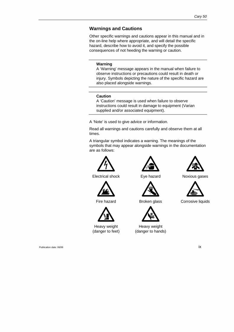
A triangular symbol indicates a warning. The meanings of thesymbols that may appear alongside warnings in the documentationare as follows:
Electrical shock Eye hazard Noxious gases
Fire hazard Broken glass Corrosive liquids
Heavy weight Heavy weight(danger to feet) (danger to hands)

Cary 50
Publication date: 06/99x
The following symbol may be used on warning labels attached tothe instrument. When you see this symbol you must refer to therelevant operation or service manual for the correct procedurereferred to by that warning label.
Power indicator
The green indicator lamp on the front of the Cary 50 indicates theinstrument is powered up (i.e. the PC is switched on) and is innormal/standby condition. When the indicator lamp is flashing thisindicates the instrument is busy.
Information symbols
The following symbols appear on the Cary 50 to provide you withadditional information:
Attached to the rear of the product, and indicatesthat the product complies with the requirementsof one or more EU Directives
Attached to the rear of the product, and indicatesthat the product has been certified (evaluated) toCSA 1010.1 and UL 3101-1.
Xe
Indicates high voltage Xenon flash lamp present
Indicates viewing hole to check the operation ofthe Xenon flash lamp
Federal Communications Commission advisory
The following is a Federal Communications Commission advisory:
Caution
This equipment generates, uses, and can radiate radio frequencyenergy and if not installed and operated in accordance with theinstruction manual, may cause interference to radio
Cary 50
Publication date: 06/99 xi
communications. It has been tested and found to comply with thelimits for a Class A computing device pursuant to Subpart J of Part15 of FCC Rules, which are designed to provide reasonableprotection against such interference when operated in acommercial environment. Operation of this equipment in aresidential area may cause interference in which case the user athis or her own expense will be required to take whatever measuresmay be required to correct the interference.
CE Compliant Products
Cary instruments have been designed to comply with therequirements of the Electro-magnetic Compatibility (EMC) Directiveand the Low Voltage (electrical safety) Directive (commonlyreferred to as the LVD) of the European Union.
Varian has confirmed that each product complies with the relevantDirectives by testing a prototype against the prescribed EN(European Norm) standards.
Proof that a product complies with the Directives is indicated by:-
❑ the CE Marking appearing on the rear of the product
❑ the documentation package that accompanies the productcontaining a copy of the Declaration of Conformity. ThisDeclaration is the legal declaration by Varian that the productcomplies with the Directives, and also shows the EN standards towhich the product was tested to demonstrate compliance.
It is also signed by Varian's Authorized Representative in the EU,and by the representative of the manufacturing plant.

Cary 50
Publication date: 06/99xii
This page is intentionally left blank.
Cary 50
Publication date: 06/99 1-1
1 Introduction
1.1 Installation requirementsPrior to receiving your instrument you will have been provided witha Cary Pre-installation manual, which describes the environmentaland operating requirements of the Cary system. You must prepareyour laboratory according to these instructions before the Cary canbe installed. You should keep the Pre-installation manual for futurereference. If you have misplaced your copy, you can obtain areplacement from your local Varian office.
1.2 Cary documentationYou have been provided with the following documentation to helpyou set up and operate your Cary 50 system:
❑ Installation Guides (one for each operating systemsupported), with information on unpacking the instrument,installing the interface card in the PC and setting up thesystem
❑ This operation manual, with Safety practices and hazardsinformation, instructions for installing and maintaining thecomponents of the Cary 50, and troubleshooting information
❑ Cary WinUV software manual, with instructions for installingthe Cary WinUV software, an overview of the software andsoftware related troubleshooting information
❑ Extensive on-line Help (provided with the Cary WinUVsoftware) containing context-sensitive help, step-by-stepinstructions for frequently performed analyses and instructionsfor using any accessories you ordered.
Cary 50
Publication date: 06/991-2
ConventionsThe following conventions have been used throughout thedocumentation:
❑ Italics indicate menu items, menu options and field names(e.g. select Copy from the Edit menu).
❑ Keyboard and mouse commands have been typed in bold(e.g. press the F2 key).
❑ Single quotes (‘ ’) indicate a selection you can make fromseveral choices, such as radio buttons and checkboxes.
❑ Double quotes (“ ”) are used to signify the pushbuttonsappearing throughout the software (e.g. select “OK”).
❑ ALL CAPITALS indicates text you must type in from thekeyboard (e.g. type SETUP at the prompt).
1.3 SpecificationsYour Cary instrument is designed for indoor use. It is suitable forthe categories stated on the front of this manual.
1.3.1 Environmental
Condition Altitude Tempt (°C)
Humidity (%RH)non-condensing
Non-operating(transport)
0-2133 m(0-7000')
5-45 20-80
Operating but notnecessarily meetingperformancespecifications
0-2000 m(0-6562')
5-3131-40
≤80≤{80-3.33(t-31)}
Operating withinperformancespecifications
0-853 m(0-2800')
10-35 8-80
853-2133 m(2800-7000')
10-25 8-80
For optimum analytical performance it is recommended that theambient temperature of the laboratory be between 20-25 °C and beheld constant to within ±2 °C throughout the entire working day.

Cary 50
Publication date: 06/99 1-3
1.3.2 Personal computerTo ensure safe operation of the instrument, the switching powersupply in the PC must comply with standard IEC 950 or equivalent.
PC power supply
The power requirements of the Cary 50 must be met by the PCpower supply and the following capacity (in addition to what isrequired by the PC itself) is required:
+5V DC <1 A
+12V DC <1.5 A
-12V DC <0.25 A,
a total of 26 W for the instrument.
Allowance must also be made for external accessories powered by+12V DC.
Operating motor driven accessories will increase the +12 V currentby a further 2 A (a maximum of 24 W for accessories).
Varian recommends a PC power supply rating of 220 W as aminimum.
1.3.3 Connections3.5 mm phono jack socket in the left hand side of the samplecompartment for accessories.
8-pin DIN connector in the left hand side of the samplecompartment for the diode detector.
25-pin D-range connector in the right hand side of the samplecompartment for accessories (optional).
1.3.4 Weights and dimensions
WeightPacked 23 kg (50.7 lb)
Unpacked 21 kg (46 lb)
Dimensions (W x D x H)Packed 615 x 710 x 360 mm (24 x 28 x 14 in)
Unpacked 590 x 500 x 200 mm (23 x 20 x 8 in)

Cary 50
Publication date: 06/991-4
This page is intentionally left blank

Cary 50
Publication date: 06/99 2-1
2 Installation
The Cary 50 is designed to be completely customer-installable.Instructions for setting up the Cary system are included in theInstallation Guides supplied with the instrument. You should selectthe one appropriate for the operating system you are using on yourPC.
WarningThe Cary 50 weighs over 20 kg. To avoid injury to personnelor damage to equipment, always use two or more peoplewhen lifting or carrying the instrument. NEVER attempt to liftthe instrument alone.
Following the instructions in the Installation Guide you shouldhave:
❑ Unpacked the spectrophotometer and placed it on theintended workbench
❑ Installed the instrument interface card in the PC (if yousupplied your own PC)
❑ Installed the Accessory Cable kit (if ordered)
❑ Connected the instrument to the PC
❑ Connected the PC to the power supply
❑ Installed the WinUVsoftware
❑ Completed the instrument performance tests.
This chapter describes how to install the sample holders used with
Cary 50
Publication date: 06/992-2
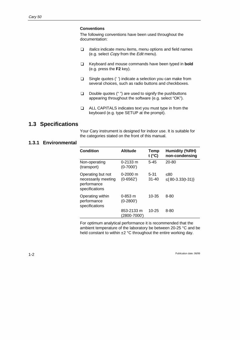
the Cary 50. Instructions for installing/replacing the lamp moduleare included in the next chapter.
1
2
Cary 50 showing the sample compartment lid (1) and front panel (2)
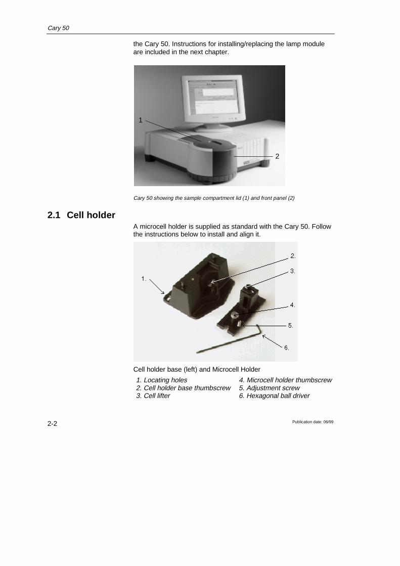
2.1 Cell holderA microcell holder is supplied as standard with the Cary 50. Followthe instructions below to install and align it.
Cell holder base (left) and Microcell Holder
1. Locating holes 4. Microcell holder thumbscrew2. Cell holder base thumbscrew 5. Adjustment screw3. Cell lifter 6. Hexagonal ball driver
Cary 50
Publication date: 06/99 2-3
2.1.1 InstallationTo install the microcell Holder:
1. Place a microcell in the microcell Holder (if the cell has groundglass sides or sides featuring the Cary logo, hold the cell bythese sides) and check that the cell aperture is verticallycentred in the cell holder aperture.
2. If the cell aperture is not at the correct height, remove the celland adjust the grub screw in the Microcell Holder accordinglyusing the hexagonal ball driver (2.5 mm). Replace the cell inthe Microcell Holder.
3. Slide back the sample compartment lid.
4. Remove the sample compartment front panel.
5. 5. If not already fitted, install the cell holder base in the samplecompartment as follows:
a. Place the cell holder base in the sample compartment, aligningthe two locating holes over the two locating pins in the floor ofthe sample compartment.
b. Firmly tighten the thumbscrew on the cell holder base (item 2in picture above).
6. Place the Microcell Holder on the cell holder base, aligning theholes in the Microcell Holder over the raised black knobs in thecell holder base.
7. Tighten the thumbscrew on the Microcell Holder.
You should now align the Microcell Holder.
2.1.2 AlignmentTo align the Microcell Holder:
1. Start the Align application by pressing the ‘Start’ button in theWindows Taskbar and selecting Programs, Cary WinUV, Align.
2. Select the Cary tab.
3. In the Instrument Parameters group, set the wavelength to 0nm (white light) by enabling the Zero Order checkbox.
4. Press ‘Apply’. (The green power indicator on the instrumentshould start flashing to indicate that the instrument is active.)

Cary 50
Publication date: 06/992-4
5. Place a cell in the Microcell Holder (if you have not alreadydone so).
6. Place a small piece of white paper in the light path to the rightof the cell. If the beam appears as though it will strike the cellaperture, move the paper to the left of the cell and check thatthe beam is passing through the cell. (If the beam does notappear as though it will pass through the cell, adjust the heightof the cell as described in 2.1.1.).
7. Using the hexagonal ball driver (2.5 mm), adjust the MicrocellHolder adjustment screw (item 5 in picture above) and note theintensity of the light striking the paper. Continue to adjust theadjustment screw until the beam hitting the paper appears themost intense.
✒ Note You may need to dim the room lights to see the light beam.
2.1.3 Other sample holdersOther sample holders are available for use with the Cary 50, suchas the Solid Sample Holder. Instructions for their use are includedin the on-line help provided with the Cary WinUV software. Refer tothe Cary WinUV manual (part number 85 101625 00) for details onusing the on-line help.
Cary 50
Publication date: 06/99 3-1
3 Maintenance
This chapter includes the maintenance procedures for the Cary 50that may be carried out by an operator. Any maintenanceprocedures not specifically mentioned in this chapter should becarried out only by Varian-trained, Varian-qualified or Varian-authorized service engineers.
WarningThis instrument contains an intense light source. Directviewing of the light source will cause eye damage. Operatorsand other unauthorized personnel must NEVER remove themain cover.
✒ Note This section refers only to maintenance procedures for the Caryspectrophotometer. You should refer to your PC and printermanuals for their maintenance procedures, and to the Cary WinUVon-line help for the maintenance procedures for any Caryaccessories you ordered.
3.1 CleaningAny spills in the sample compartment should be wiped upimmediately.
The exterior surfaces of the Cary spectrophotometer should bekept clean. All cleaning should be done with a soft cloth. Ifnecessary, this cloth can be dampened with water or a milddetergent. Do not use organic solvents or abrasive cleaningagents.

Cary 50
Publication date: 06/993-2
3.2 Lamp moduleThis section describes how to replace the lamp module and re-align the light beam. Before changing the lamp module, ALWAYSdisconnect the Cary 50 from the PC.
✒ Note These instructions are also provided on-line with the Cary WinUVsoftware, together with video to demonstrate the procedure. Referto the Cary WinUV manual (publication number 85 101625 00) fordetails on using the on-line help.
3.2.1 Lamp module replacement
WarningWhen operating, the lamp module emits high intensity lightwhich can damage eyes. To avoid eye damage, never operatethe lamp module outside the instrument.The lamp module contains components operating at highvoltages. To avoid electric shock, NEVER disassemble thelamp module.
To remove the lamp module:
1. Remove the plug from the ‘inst’ connector on the rear panel ofthe Cary 50.
2. Turn the Cary onto its side to give access to the base.
Cary 50
Publication date: 06/99 3-3
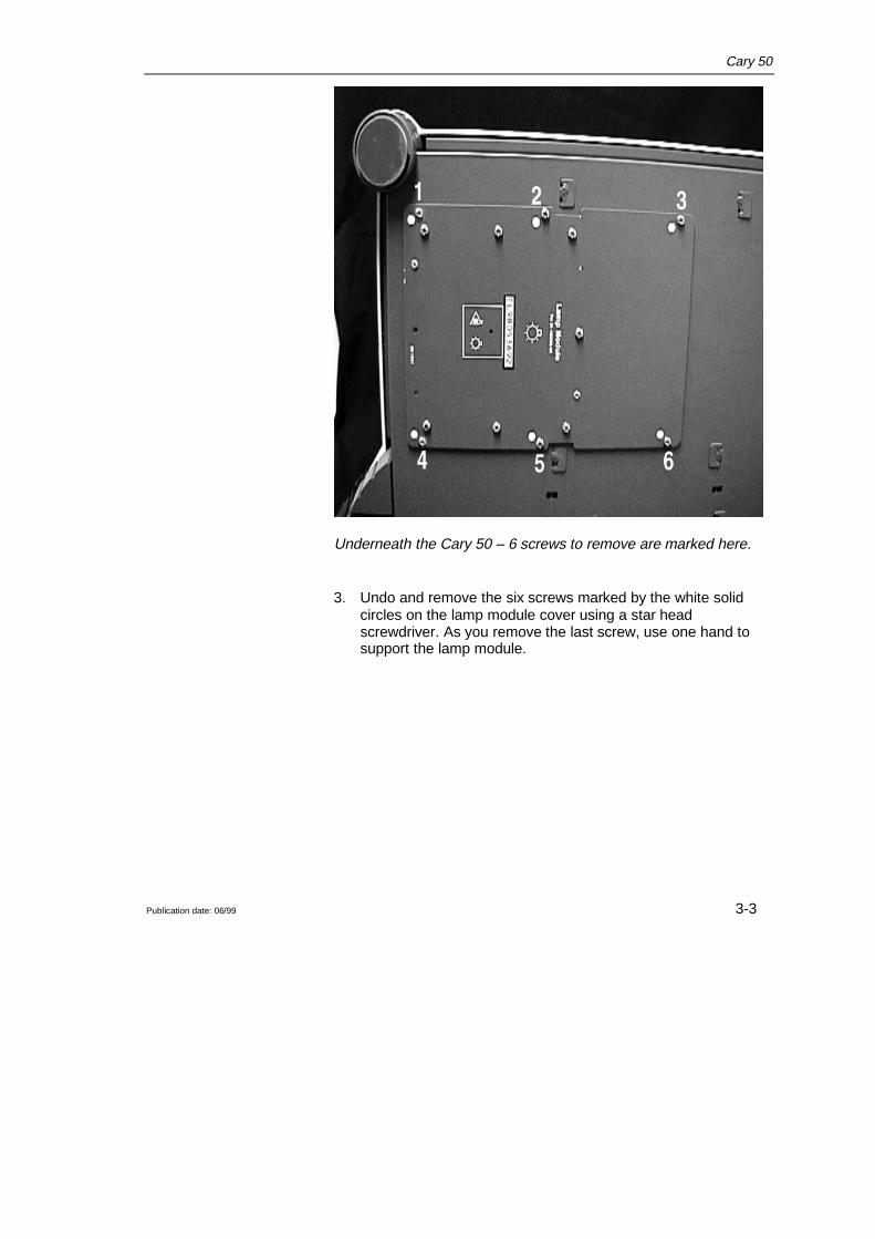
Underneath the Cary 50 – 6 screws to remove are marked here.
3. Undo and remove the six screws marked by the white solidcircles on the lamp module cover using a star headscrewdriver. As you remove the last screw, use one hand tosupport the lamp module.
Cary 50
Publication date: 06/993-4
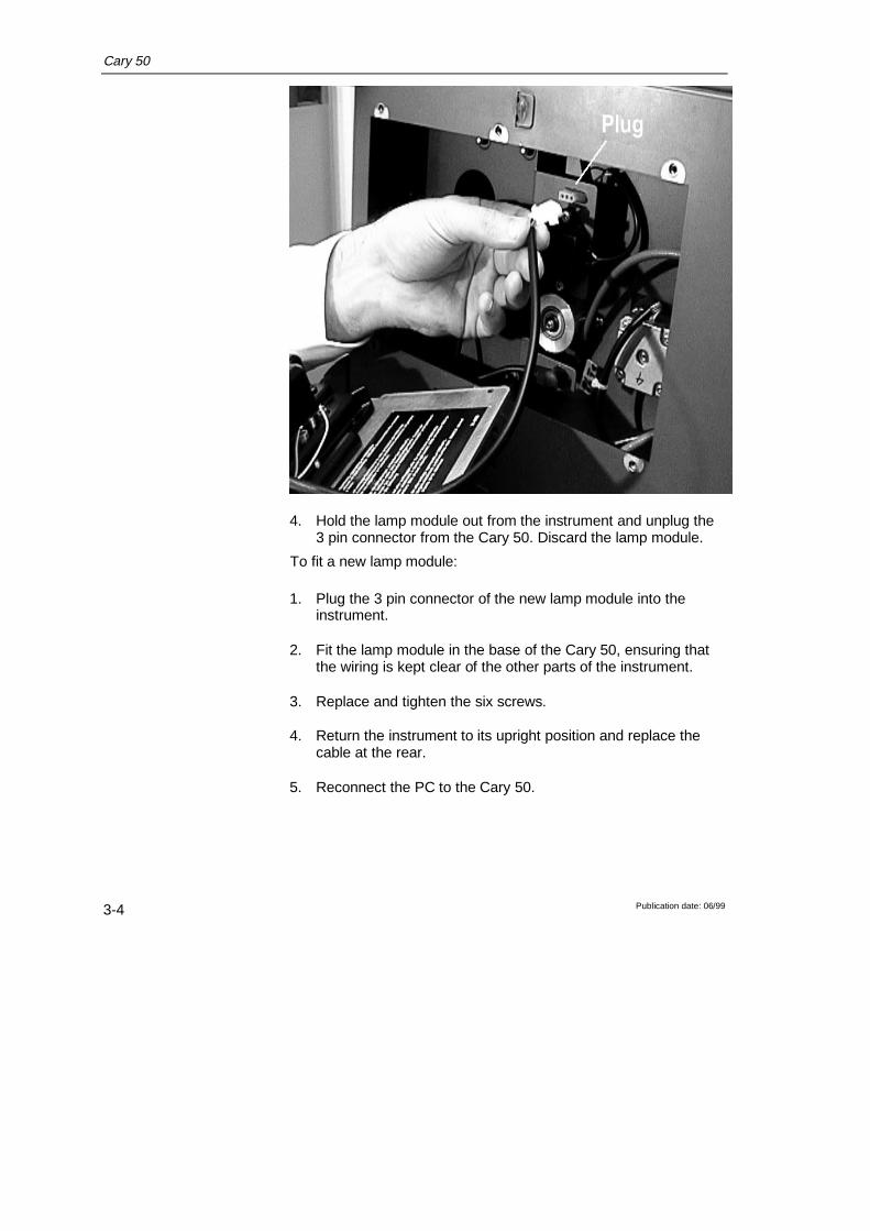
4. Hold the lamp module out from the instrument and unplug the3 pin connector from the Cary 50. Discard the lamp module.
To fit a new lamp module:
1. Plug the 3 pin connector of the new lamp module into theinstrument.
2. Fit the lamp module in the base of the Cary 50, ensuring thatthe wiring is kept clear of the other parts of the instrument.
3. Replace and tighten the six screws.
4. Return the instrument to its upright position and replace thecable at the rear.
5. Reconnect the PC to the Cary 50.
Cary 50
Publication date: 06/99 3-5
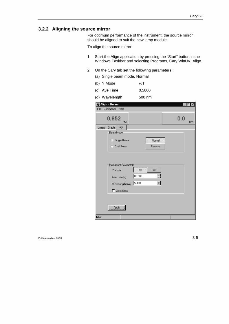
3.2.2 Aligning the source mirrorFor optimum performance of the instrument, the source mirrorshould be aligned to suit the new lamp module.
To align the source mirror:
1. Start the Align application by pressing the “Start” button in theWindows Taskbar and selecting Programs, Cary WinUV, Align.
2. On the Cary tab set the following parameters::
(a) Single beam mode, Normal
(b) Y Mode %T
(c) Ave Time 0.5000
(d) Wavelength 500 nm
Cary 50
Publication date: 06/993-6
3. Press “Apply”.
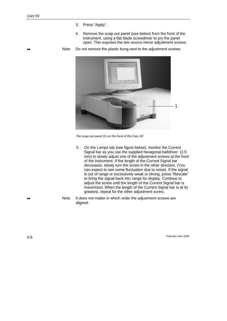
4. Remove the snap-out panel (see below) from the front of theinstrument, using a flat blade screwdriver to pry the panelopen. This exposes the two source mirror adjustment screws.
✒ Note Do not remove the plastic bung next to the adjustment screws.
1.
The snap-out panel (1) on the front of the Cary 50
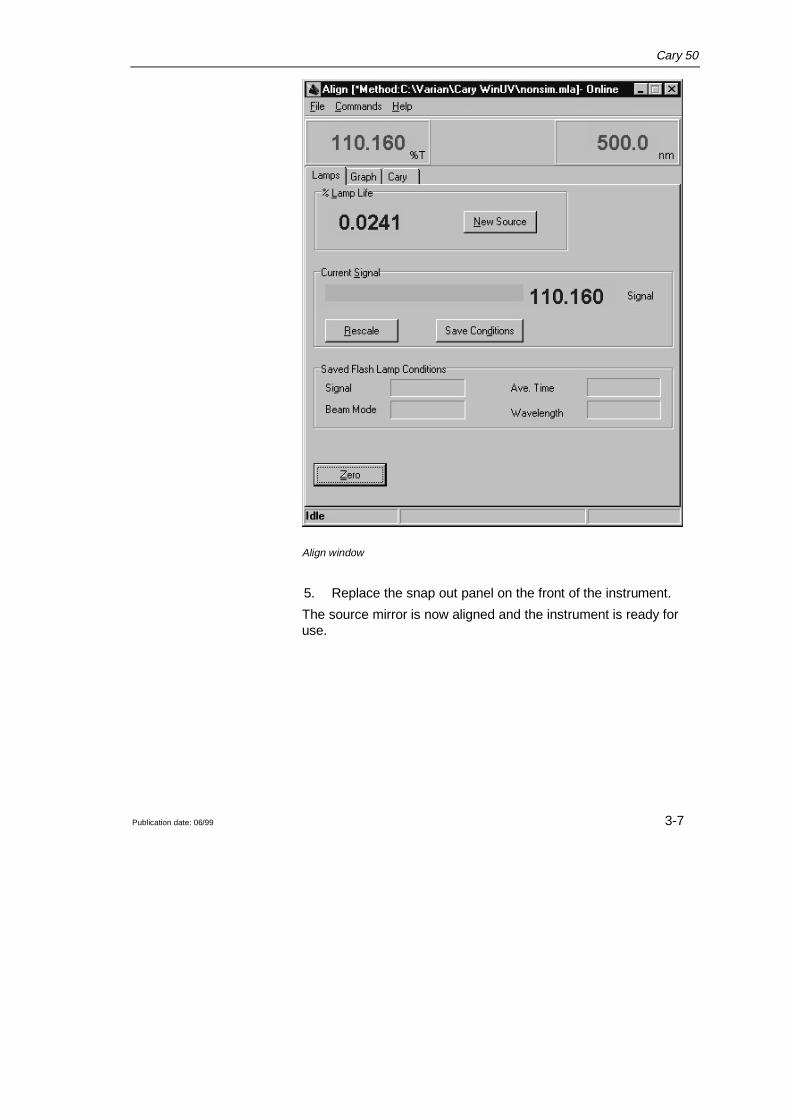
5. On the Lamps tab (see figure below), monitor the CurrentSignal bar as you use the supplied hexagonal balldriver (2.5mm) to slowly adjust one of the adjustment screws at the frontof the instrument. If the length of the Current Signal bardecreases, slowly turn the screw in the other direction. (Youcan expect to see some fluctuation due to noise). If the signalis out of range or excessively weak or strong, press “Rescale”to bring the signal back into range for display. Continue toadjust the screw until the length of the Current Signal bar ismaximized. When the length of the Current Signal bar is at itsgreatest, repeat for the other adjustment screw.
✒ Note It does not matter in which order the adjustment screws arealigned.
Cary 50
Publication date: 06/99 3-7
Align window
5. Replace the snap out panel on the front of the instrument.
The source mirror is now aligned and the instrument is ready foruse.

Cary 50
Publication date: 06/993-8
This page is intentionally left blank

Cary 50
Publication date: 06/99 4-1
4 Troubleshooting
This chapter contains troubleshooting information to help you solvevarious problems you may encounter when setting up or using yourCary 50 hardware.
4.1 Installing a Cary 50 under Windows NTWindows NT 4 is not Plug and Play. However it will reportinitialization failures of device drivers loaded during NT startup.
Make sure that you have completed all the following steps for aninstallation of the Cary 50 under Windows NT.
� Install Windows NT 4.01 or an NT foreign language version.
� Install Service pack 4 or greater
� Install Microsoft’s Internet Explorer 4.0 or later
� Shut down Windows NT
� Restart the PC
� Ensure that all devices within the system have drivers installedand that the devices are operational. eg. Sound cards producesound, SCSI cards allow access to drives. If another hardwaredevice is installed the device drivers should be installed prior toinstallation of the WinUV software
✒ Note Some PC’s have hardware built into the motherboard (eg. Soundcards, Network adapters (NIC) etc. If you wish to use devices otherthan those available on the mother board you must disable themotherboard devices in the system BIOS (consult your PCdocumentation). This will free the device resources (ie. IRQ and I/Oaddress space).
� Follow the Start here Windows NT guide (supplied with theCary instrument) to install the Cary 50 PC card.
� Restart Windows NT
Cary 50
Publication date: 06/994-2
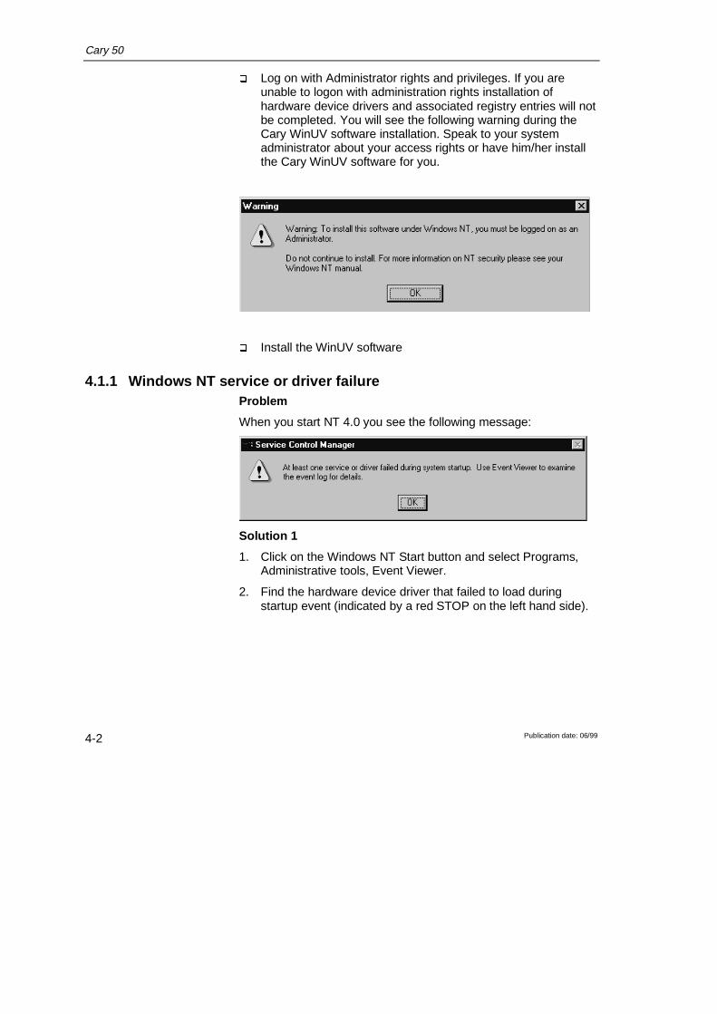
� Log on with Administrator rights and privileges. If you areunable to logon with administration rights installation ofhardware device drivers and associated registry entries will notbe completed. You will see the following warning during theCary WinUV software installation. Speak to your systemadministrator about your access rights or have him/her installthe Cary WinUV software for you.
� Install the WinUV software
4.1.1 Windows NT service or driver failureProblem
When you start NT 4.0 you see the following message:
Solution 1
1. Click on the Windows NT Start button and select Programs,Administrative tools, Event Viewer.
2. Find the hardware device driver that failed to load duringstartup event (indicated by a red STOP on the left hand side).

Cary 50
Publication date: 06/99 4-3
3. Double click on the failed event to determine the cause of thefailed device. If it was the Cary 50 that failed to load you willsee the following description:
Cary 50
Publication date: 06/994-4
4. This generally means that the device driver loaded but therewas no response from the Cary 50 instrument. This indicatesthat the Cary 50 interface hardware is not responding.
5. Ensure that the Cary 50 card is installed correctly and that theinterconnecting cable is secure.
Solution 2
Another cause of this error may be due to a conflict between theCary 50 driver and another driver on the system. This is more likelyto happen on a Windows NT system. The most common cause is asound card for which a driver has not been installed. The PC mayhave a sound card built into the motherboard as well as a separatesound card which the PC recognizes but doesn’t have a driverinstalled for.
You will need to:
1. Un-install the Cary WinUV software (refer to 4.4).
2. Un-install the Cary 50 driver by referring to section 4.3.
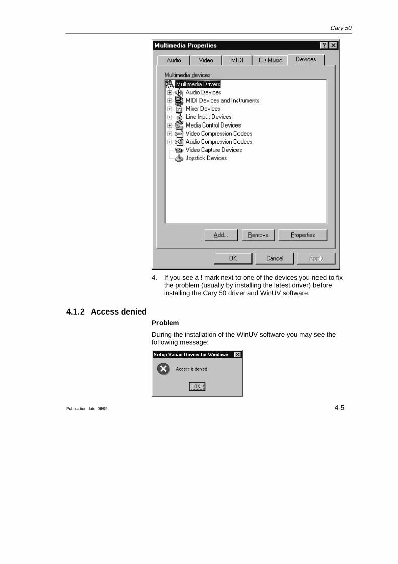
3. Click Start, Settings, Control Panel, Multimedia (for a NTsystem) or System (for a Win 95 or 98 system). Select theDevices tab (NT) or Device Manager tab (Win 95/98).
Cary 50
Publication date: 06/99 4-5
4. If you see a ! mark next to one of the devices you need to fixthe problem (usually by installing the latest driver) beforeinstalling the Cary 50 driver and WinUV software.
4.1.2 Access deniedProblem
During the installation of the WinUV software you may see thefollowing message:

Cary 50
Publication date: 06/994-6
Solution
You must be logged on with administrator rights to install theWinUV software. Click on the Windows NT Start button, selectShutdown and then Close all programs and log on as a differentuser. When prompted, log on as an Administrator or ask your NTAdministrator to log on for you. Start the WinUV installationprocess again.
4.1.3 Fcary service failed to startProblem
After the installation of the WinUV software the following messageis displayed:
Solution
This indicates the Cary 50 device driver was not copied to thecorrect directory.
It is possible you may not have access rights to the installationdrive.
Logon with administration rights (refer to 4.1.2 ) and perform theCary WinUV installation again.

Cary 50
Publication date: 06/99 4-7
4.1.4 There is no green light indicating that the Cary 50 is powered.The Cary 50 is powered directly from the PC power supply. Agreen power indicator light on the front of the Cary 50 indicateswhen the instrument is powered.
Problem
The power indicator on the Cary 50 does not light when the PC isswitched on.
Solution
Check the connection of the main instrument cable connecting thePC to the Cary 50.
If the power indicator on the front of the Cary 50 is still not on,check the connection of the PC power supply connector to theCary 50 card inside the PC. Instructions for the connection of thepower supply connector are listed in the Installation Guide suppliedwith your Cary 50 (and in section 4.1.6 if you need to use a Yconnector).
4.1.5 Start button replaced with Connect buttonProblem
I have a ‘Connect’ button instead of a ‘Start’ button. What does thismean?
Answer
Only one Cary application can communicate with the instrument ata time. When you turn the PC on the System informationapplication initializes the Cary 50 and checks that it is workingcorrectly. If you start another application e.g. Scan before thisinitialization has finished the application will have a ‘Connect’button instead of a ‘Start’ button. Just wait for the status line at thebottom of the application to display ‘idle’ and then click on theConnect button and it will change to a Start button.
Problem
The Connect button will not change to Start.
Answer
If the Cary software cannot locate the Cary 50 PC card then theConnect button will not change to Start. This is due to either:
• A memory address conflict with the Cary 50 PC card andanother card in the PC.
Cary 50
Publication date: 06/994-8
• An IRQ conflict with another card
• An I/O address conflict with another card.
• A defective IEEE or Cary 50 PC card.
Under Windows NT the best way to fix the problem is to:
1. Remove as many other cards from the PC as possible e.g.sound or network card, de-installing their drivers as well.
2. De-install the Cary driver (refer to 4.3)
3. Re-boot the PC.
4. Re-install the Cary software.
5. Check that the PC is now communicating with the Caryinstrument (the Connect button should change to Start whenyou click on it).
6. Re-install the other cards, specifying another IRQ and/ormemory address if possible. If you can’t change these then youmay have to purchasedifferent cards which allow moreflexibility in changing the IRQ and/or memory address.
4.1.6 Hard disk power supply connectionProblem
There is not a spare hard disk power supply connector in the PC toconnect to the Cary 50 PC card.
Solution
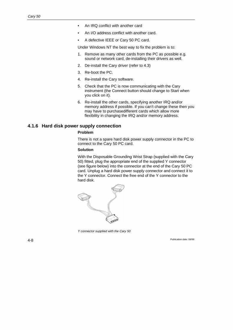
With the Disposable Grounding Wrist Strap (supplied with the Cary50) fitted, plug the appropriate end of the supplied Y connector(see figure below) into the connector at the end of the Cary 50 PCcard. Unplug a hard disk power supply connector and connect it tothe Y connector. Connect the free end of the Y connector to thehard disk.
Y connector supplied with the Cary 50
Cary 50
Publication date: 06/99 4-9
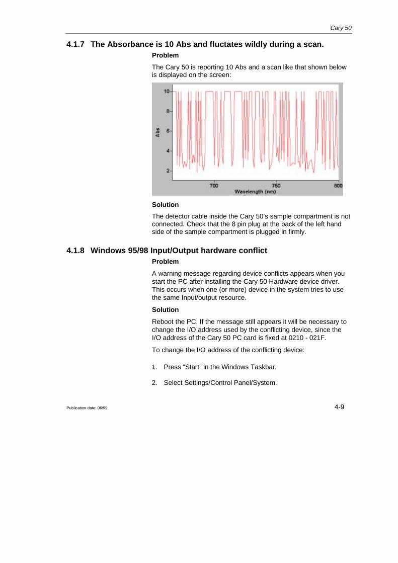
4.1.7 The Absorbance is 10 Abs and fluctates wildly during a scan.Problem
The Cary 50 is reporting 10 Abs and a scan like that shown belowis displayed on the screen:
Solution
The detector cable inside the Cary 50’s sample compartment is notconnected. Check that the 8 pin plug at the back of the left handside of the sample compartment is plugged in firmly.
4.1.8 Windows 95/98 Input/Output hardware conflictProblem
A warning message regarding device conflicts appears when youstart the PC after installing the Cary 50 Hardware device driver.This occurs when one (or more) device in the system tries to usethe same Input/output resource.
Solution
Reboot the PC. If the message still appears it will be necessary tochange the I/O address used by the conflicting device, since theI/O address of the Cary 50 PC card is fixed at 0210 - 021F.
To change the I/O address of the conflicting device:
1. Press “Start” in the Windows Taskbar.
2. Select Settings/Control Panel/System.

Cary 50
Publication date: 06/994-10
3. Select the Device Manager tab.
4. Expand ‘Other devices’ and select Varian Cary 50. Theconflicting device will appear in the Conflicting device list.Press “Cancel’ to return to the Device Manager tab.
5. Locate the conflicting device in the list and double click on it.
6. On the Resources tab, deselect ‘Use automatic settings’ andchange the Input/Output address until the message “NoConflicts” appears in the Conflicting device list.
4.1.9 No free Interrupt requestProblem
There is not a spare Interrupt request available for the Cary 50.
Solution
Disable a device which you do not use frequently, for example asound card.
To disable the device:
1. Press “Start” in the Windows Taskbar.

Cary 50
Publication date: 06/99 4-11
2. Select Settings/Control Panel/System.
3. Select the Device Manager tab.
4. Double click on the device you want to disable.
5. On the General tab, disable the ‘Original Configuration’checkbox.
4.2 Instrument performance testingProblem
The results of your instrument performance tests do not meetspecifications (the results obtained during factory testing areincluded in the packing crate with the instrument).
Solution
Check the following:
❑ The sample compartment is empty.
Cary 50
Publication date: 06/994-12
❑ The cable connecting the instrument to the PC is correctlyconnected and the retaining screws are tightened.
❑ The lamp is pulsing during initialization. This is indicated if thegreen power indicator on the front of the instrument flashes(you should also hear the monchromator and the filter wheelmoving). You should also turn the instrument on its side andlook through the small lamp viewing hole in the base of theinstrument. If the lamp is not pulsing you may have ahardware conflict (see sections 4.1.8).
❑ The lamp is correctly aligned (refer to Chapter 3 forinstructions on aligning the lamp).
WarningWhen operating, the lamp module emits high intensity lightwhich can damage eyes. To avoid eye damage, never operatethe lamp module outside the instrument.The lamp module contains components operating at highvoltages. To avoid electric shock, NEVER disassemble thelamp module.
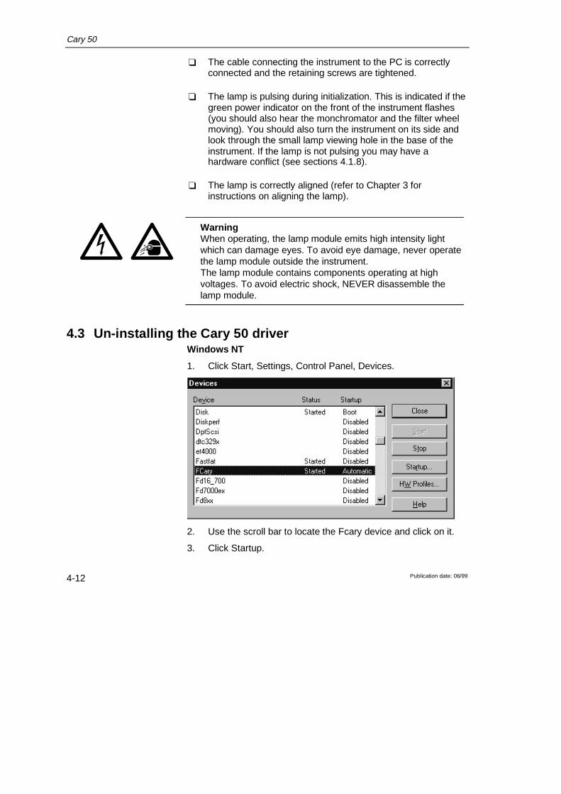
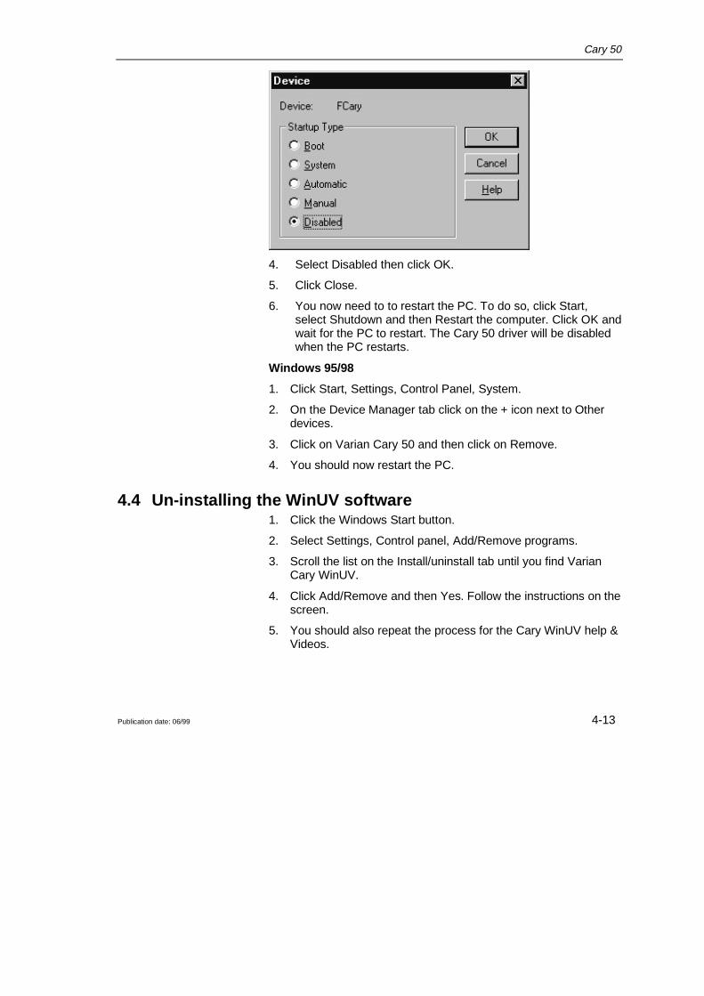
4.3 Un-installing the Cary 50 driverWindows NT
1. Click Start, Settings, Control Panel, Devices.
2. Use the scroll bar to locate the Fcary device and click on it.
3. Click Startup.
Cary 50
Publication date: 06/99 4-13
4. Select Disabled then click OK.
5. Click Close.
6. You now need to to restart the PC. To do so, click Start,select Shutdown and then Restart the computer. Click OK andwait for the PC to restart. The Cary 50 driver will be disabledwhen the PC restarts.
Windows 95/98
1. Click Start, Settings, Control Panel, System.
2. On the Device Manager tab click on the + icon next to Otherdevices.
3. Click on Varian Cary 50 and then click on Remove.
4. You should now restart the PC.
4.4 Un-installing the WinUV software1. Click the Windows Start button.
2. Select Settings, Control panel, Add/Remove programs.
3. Scroll the list on the Install/uninstall tab until you find VarianCary WinUV.
4. Click Add/Remove and then Yes. Follow the instructions on thescreen.
5. You should also repeat the process for the Cary WinUV help &Videos.

Cary 50
Publication date: 06/994-14
This page is intentionally left blank

Cary 50
Publication date: 06/99 5-1
5 Spare parts
The following spare parts are available for use with your Cary 50instrument. Always use Varian-supplied spare parts, unlessotherwise indicated.
2
1
3
4
1. Sample compartment lid 09 101272 00
2. Sample compartment front panel 01 106429 90
3. Lamp mirror adjustment cover 09 101274 00
4. Accessory cable port plate (rear of instrument) 09 101240 00
Xenon Lamp module 01 106396 90
Cary 50 PC card 02 101557 90
Cary 50 PC interconnecting cable 01 106373 90
3M Disposable Grounding Wrist Strap 79 100313 00
Cary mouse pad 79 100223 00
Ordering details for other Cary 50 accessories are available in theParts and Supplies catalog included on-line with the Cary WinUVsoftware.

Cary 50
Publication date: 06/995-2