Embed Size (px)
DESCRIPTION
SMMSi indoor/outdoor unit
Citation preview


Earth can hardly wait for a change in the atmosphere. Nor can we.By making air conditioning supremely energy-efficient, quiet, easy
to install, and cost-effective, Toshiba aims at the heart of growing global pollution.
Such inspiration takes team spirit even more than competitive spirit. We lead initiatives with innovators in academia, industry and government to think bigger, act bolder and move faster toward more eco-friendly solutions. To sustain better qualities of life, we have to take better care of business and the environment in the long run.
Change is in the air. Together, we can all make a world of difference.
1

The Super Modular Multi System opens up a new dimension in air conditioning.
World’s best class energy savings Greater installation flexibility Improved operation control
2

3

5 Feature5 World’s Best Class Energy Savings
9 Greater Installation Flexibility11 Improved Operation Control
13 Model Line-up13 Outdoor unit
18 Indoor unit19 4-way Air Discharge Cassette Type21 Compact 4-way Cassette (600 × 600) Type23 2-way Air Discharge Cassette Type25 1-way Air Discharge Cassette Type27 Concealed Duct Type29 Concealed Duct High Static Pressure Type31 Slim Duct Type33 Ceiling Type35 High-wall Type (1 series)
36 High-wall Type (2 series) *European market only
37 Floor Standing Concealed Type38 Floor Standing Cabinet Type39 Floor Standing Type40 Fresh Air Intake Indoor Unit Type
43 Indoor Unit Accessories
45 Refrigerant Piping Design
48 Wiring Design
51 Operating Temperature Range
53 Wide Control Applications
55 Network Control
57 Remote Controller
61 Application controls by the optional P.C. board of outdoor units
Contents SMMS AIR CONDITIONING FOR LARGE BUILDINGS
4

3.5
4.0
4.5
5.0
5.5
6.0
4.634.54 4.56
3.83
4.56
3.833.833.95
COP
10HP 20HP 30HP 40HP HP
100% 80% 50% Heating temperature condition: Outdoor 7ºCdb/6ºCwb, Indoor 20ºC
5.735.735.51 5.54 5.53
World’s Best Class Energy Savings
htime5 6 7 8 9 10 11 12 13 14 15 16 17 18 19 20 21
%
Cap
acity
load
Capacity load
0
20
40
60
80
100
COP of 4.25* achieved by Toshiba’s unrivalled Super Modular Multi System (SMMS) technologies and newly developed components* 8HP CDU system, heating operation
SMMS high performance COPPartial load performance is the most important value for a VRF
with fluctuating performance due to changes in the number of
units operating and/or fluctuations in the air conditioning load.
(100–50% partial load operation)
New high-performance bell mouth with smooth flow
Enlarged suction radius provides smoother flow.
High output / high-efficiency DC motor
DC fan motor- Pressure fluctuations
due to interference have been suppressed.
- Efficiency is high, and noise has been reduced.
600 W output
World’s best class partial load COP
Part load operation A VRF system can achieve energy efficient operation
especially in a separated room layout as shown. Not all of
the indoor units operate at the same time so the system is
almost always operating with a partial indoor unit load.
Capacity load curve (Example of an office)
Vector-controlled inverterThe inverter boosts efficiency by controlling R410A and a twin-rotary DC compressor.
Efficient circuit built-in; new PIM
Smooth sine curve realizes higher efficiency and less noise.
5

World’s B
est Class Energy S
avingsG
reater Installatio
n Flexib
ilityIm
pro
ved O
peratio
n Co
ntro
l
New large-diameter propeller fan (flash wing fan)
The concave leading edge of the fan blades reduces flow interference between adjacent blades.
Enlarged fan diameter φ630→ φ710
Concave leading edge
Outdoor heat-transfer- Compact heat-transfer
tube with intakes on four sides.
- Heat-transfer tube with improved heat-transfer coefficient of the inner surface.
Configuration of the finned heat-transfer tube
Twin-rotary DC compressorTwo DC twin-rotary compressors (dual configuration) are equipped per module (basic outdoor unit)
DC driven motor with rare earth magnet - Compact- Higher efficiency- Higher power motor torque
Partial load range* Most frequent
operationStandard range
Tota
l effi
cien
cy o
f com
pres
sor
(%)
DC twin-rotary typePrevious Scroll type
Frequency of compressor (rps)
This difference is the reason for actual energy savings
Comparison of DC twin-rotary and Previous Scroll Compressors
R410A refrigerantAn ozone layer depletion coefficient of zero has become absolutely essential for an advanced air conditioning system.
UV-RAY
OZONE LAYER
Ozone depletion potential(ODP) 0
Refrigerant capability(*comparison with R22)
Pressure loss(*comparison with R22)
Ozone depletion potential(ODP)
Refrigerant capability(*comparison with R22)
Pressure loss(*comparison with R22)
147%
56%
0
R410A R407C
100%
106%
Precise manufacturing technology in the compression parts- Higher efficiency (in wide range)- Higher reliability
6

Reliability
With dual-rotation, the load is distributed more evenly — this
means that the operating sequence of the outdoor units and the
individual compressors is rotated to spread the operating hours
more evenly.
As the compressors are all inverter driven, power surges are
eliminated. Over- or under-utilisation of power, typical for non-inverter
compressors is eliminated, and there is no on/off power surge as the
system adjusts to the demand required by the occupant or system.
The use of inverter compressors reduces the risk of compressor
failure, more common in standard non-inverter systems.
Energy savings
During operation the system determines which heat exchanger
can be used most efficiently and selects the compressor to deliver
the power required. Inverter systems save energy as continuous
operation offers the same capacity with lower power consumption.
This benefits all occupants by maintaining even room temperatures,
as well as the environment by reducing energy consumption.
High-efficiency DC twin-rotary compressorsEvery outdoor unit incorporates two new DC twin-rotary compressors and dual-inverter drives — this is unique to Toshiba
and the air conditioning industry.
DC twin-rotary compressor advantageThis is a comparison of compressor energy efficiency by compressor rotation.
SMMS use twin-rotary inverter compressor, energy efficiency through all range of compressor rotation is more stable than
scroll type compressor in characteristic.
Scroll compressor can achieve high-efficiency operation in narrow scope.
As the VRF air conditioner required a wide range of capacity, a twin-rotary compressor is well-suited for the VRF.
A B C
1 2 3 4 5 6
(base unit)
Rotation between outdoor units
Com
pres
sor
Com
pres
sor
Com
pres
sor
Com
pres
sor
Com
pres
sor
Com
pres
sor
Sequencing of individual compressors(compressors 1 and 2 , compressors 3 and 4 ,
compressors 5 and 6 )
heat
exc
hang
ers
Operate Stop Operate Operate
2 4312 431
ONON ON OFFOFF OFF ON OFF
Conventionalsystem
System with controlledreliability and savings
Using greater heat exchanger volume is more efficient
Invertercompressor
Invertercompressor
Invertercompressor
Invertercompressor
Invertercompressor
Fixed-speedcompressor
Fixed-speedcompressor
Fixed-speedcompressor
DC fan motor
Vector-controlled inverter
All outdoor units are fitted with two DC twin-rotary compressors (switch to all-inverter models)
7

World’s B
est Class Energy S
avingsG
reater Installatio
n Flexib
ilityIm
pro
ved O
peratio
n Co
ntro
l
World’s Best Class Energy Saving
Toshiba Carrier Commitment to the Environment- Reduced level of emission of CO2
Protects against global warming
Response to energy problems
Established and promoted goals for reducing the amount of energy used in all
production activities
25% improvement per basic unit in total sales by 2010 taking 1990 as a reference
- Reduced level of emission of chemical substances 30% reduction by 2005 taking 2000 as a reference
- Zero emission of harmful substancesAchieved zero emission of harmful substances in 2003
(Defined as an overall emission level of 1% or less of harmful substances)
- Complete elimination of HCFC refrigerants
Positive response to CFC problemsCompletely eliminated by 2004
- Reduced power consumption per product function
- Development of environmentally harmony products
- Utilization of lead-free solder
This technologically advanced product has received honors from public organizations in Japan.
2003Energy Conservation Grand Prize
Winner of the “Resource Energy Secretary’s Prize”
2004Japan Society of Refrigerating and Air Conditioning Engineers
Winner of the “Technology Award”
2005The Institute of Electrical Engineers of Japan
Winner of the Electrical Learning Advancement Prize “Promotion Prize”
Product: Super Module Multi“Cooling/Heating Selection” Series
Product: Super Module Multi“Cooling/Heating Selection” Series
Product: Super Module Multi “Cooling/Warming Flex” Series
This product has been honored as an energy
consuming system with superior energy and
resource conservation features contributing to
reduced emission of global warming gases.*
(Energy Conservation Center, Japan)
This product was praised as a particularly
technologically advanced product in terms of
hardware and installation in the field of cooling
and air conditioning.
(Japan Society of Refrigerating and Air
Conditioning Engineers)
This product was mentioned for its remarkable
results for a proposed or demonstrated new
logic, device, or system made into a product
or facility using electricity-related learning or
technology.
(The Institute of Electrical Engineers of Japan)
2005Winner of “Promotion Prize”
(The Institute of Electrical Engineers of Japan)For “the development and application
of a vector control inverter”
2005Winner of “Promotion Prize”
(The Institute of Electrical Engineers of Japan)For “the development and application
of a vector control inverter”
2005Winner of “Promotion Prize”
(The Institute of Electrical Engineers of Japan)For “the development and application
of a vector control inverter”
* Energy Conservation Grand Prize Models MMY-MAP1401H, MMY-MAP1601H, MMY-MAP2241H, MMY-MAP2801H, MMY-MAP3351 MMY-AP3841H, MMY-AP4501H, MMY-AP5041H, MMY-AP5601H, MMY-AP6151H, MMY-AP6151H1, MMY-AP6801H, MMY-AP6801H1, MMY-AP7301H, MMY-AP7851H, MMY-AP8401H, MMY-AP9001H,
MMY-AP9001H1, MMY-AP9601H, MMY-AP9601H1, MMY-AP10101H, MMY-AP10101H1, MMY-AP10651H, MMY-AP11201H, MMY-AP11801H, MMY-AP12351H, MMY-AP13001H, MMY-AP13501H
8

Greater Installation Flexibility
Farthest equivalent length: 175 mMaximum actual length: 150 m
Max
imum
leng
th fr
om fi
rst
bra
nch:
65
m
Max
imum
ind
oor
diff
eren
ce: 3
0 m
Max
imum
hei
ght
diff
eren
ce -
Out
doo
r un
it is
hig
her
than
ind
oor
unit:
50
mO
utd
oor
unit
is lo
wer
tha
n in
doo
r un
it: 4
0 m
The pipe runs for the SMMS have been extended to offer
greater application flexibility.
Flexible branchingThe versatility of the SMMS means that
virtually any imaginable configuration
of the refrigerant Y-type branches and/
or header piping can be used in an
application to give the shortest, most
cost-effective piping installation.
The piping can be run in any direction
to facilitate refurbishment work.
Y jointHeader Branch
Y joint
CDU
CDU
CDU
CDU
CDU
Y joint
Header Branch
Header Branch
Header Branch
Y jointHeader Branch
Y joint
CDU
CDU
CDU
CDU
CDU
Y joint
Header Branch
Header Branch
Header Branch
Y jointHeader Branch
Y joint
CDU
CDU
CDU
CDU
CDU
Y joint
Header Branch
Header Branch
Header Branch
Toshiba SMMS Only
Extended piping capabilities Maximum actual length 150 m
Farthest equivalent length 175 m
Extension 300 m
Maximum height difference, outdoor unit is
higher than indoor unit50 m
Maximum height difference, outdoor unit is
lower than indoor unit40 m
Maximum height difference between indoor units 30 m
Maximum length from first branch 65 m
The diameter of the liquid and gas pipes is reduced due to the
utilisation of R410A refrigerant (in some units). More effective
use of pipe shafts is also possible, resulting in greater savings in
installation costs.
Previous (R407C) — φ gas 38.1 mm – liquid 19.1 mm
SMMS (R410A) — φ gas 28.6 mm – liquid 15.9 mm
(20HP type diameters compared)
9
World’s B
est Class Energy S
avingsG
reater Installatio
n Flexib
ilityIm
pro
ved O
peratio
n Co
ntro
l
Up to 48 units can be connected at up to 135%
outdoor unit capacity in a single cooling system.
- Allows smooth response to floors with small
rooms and tenants who change layouts often.
Wide variety in our indoor unit line-upWorld-class line-up of 14 types of indoor units.
Up to 48 indoor unit connections
30 m
Height between indoor and outdoor units (Outdoor unit higher than indoor unit)
World’s Top
Class
10
Improved Operation Control
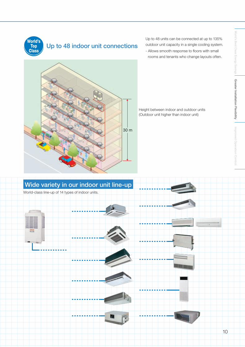
Optimal refrigerant control– When a multiple number of indoor units are
connected, an insufficient or excess amount
of refrigerant may be supplied to indoor units
depending on the difference in length of the
connection pipe from the outdoor unit.
– This is caused by pressure loss and heat
leaks as the refrigerant travels through the
pipes, resulting in incorrect amounts of
refrigerant being supplied to the indoor units.
– Optimal refrigerant control uses a multiple
number of refrigerant sensors to detect the
air conditioning status of each indoor unit
and control the capacity (refrigerant amounts)
very precisely to eliminate the variations.
Back-up functionIn the unlikely event of one compressor within an outdoor unit failing, it
is possible in most circumstances to operate the second compressor
on its own simply by setting a switch on the interface PCB. In the case
of a complete outdoor unit failure, select another outdoor unit to be the
header unit. In multiple outdoor unit systems any unit can be selected
to be the header unit.
Night operation (sound reduction) control(with optional PC Board (TCB-PCMO2E) and locally supplied timer/switch)
The unit also comes with a night-time low-noise mode, which reduces operating
noise at the programmed activation time.
Day Night
* Refer to page 61 “Application controls by the optional P.C. board of outdoor unit.”
Pulse motor valve
Indoor unit Refrigerantsensor (In)
Refrigerantsensor (Out)
A B C
D
TC2 TC1
Heatexchanger
Outdoor unit
Target capacity
(A) (B) (D)(C)
Cap
acity
The surplus represented by (A) is diminished.
The surplus represented by (A) is diminished and the deficiency represented by (D) is compensated for.
The surplus represented by (B) is diminished and the deficiency represented by (C) is compensated for.
Equivalent HP Normal Night Equivalent HP
5HP 55dB 50dB 5HP
6HP 56dB 50dB 6HP
8HP 57dB 50dB 8HP
10HP 58dB 50dB 10HP
12HP 59dB 50dB 12HP
Header unit Follower unit Follower unit
Operation continues
FailureChanged to
the header unit
If the Header Unit (Parent Unit) happens
to break down
11
World’s B
est Class Energy S
avingsG
reater Installatio
n Flexib
ilityIm
pro
ved O
peratio
n Co
ntro
l
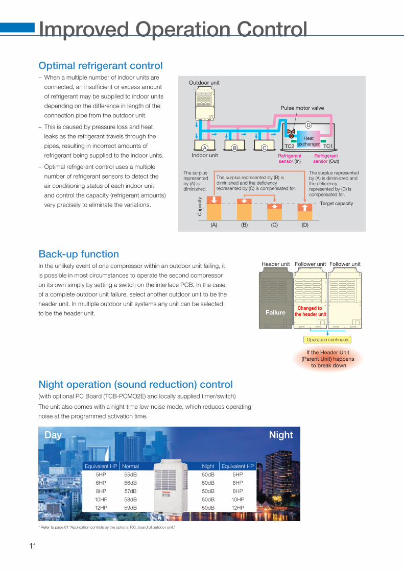
Toshiba Original
These controls realize stable oil supplies.
1) Oil balance control2) Oil supply control3) Oil supply control between outdoor units
Oil level
detection
system
1) Oil balance controlThis control equalizes amount of oil between two compressors.
3) Oil supply control between outdoor unitsThis control supplies oil accumulated in the oil tank of each outdoor unit to
the outdoor unit with insufficient oil.
2) Oil supply controlThis control accumulates oil in the oil separator. When oil is insufficient, the
system supplies oil to the compressors.
Compressor 1 Compressor 2
Comp. 1 Comp. 2
Oil tank
dischargeOil Flow
Oil balance circuit
Outdoor unit
Comp. 1 Comp. 2
Outdoor unit
Comp. 3 Comp. 4
Outdoor unit
Comp. 5 Comp. 6
Oil balance pipe
Oil Flow
Oil tank
Oil separator
discharge
suction
Supply oil to compressors
Solenoid valve is opened
Comp. 1 Comp. 2
12

Model Line-upChoose from a line-up of 28 outdoor units and 75 indoor units. Design with greater freedom
than ever before, by linking up to 48 indoor units together in one system.
Outdoor unit line-up
HP Cooling Capacity
Heating capacity
(H/P only)
Model nameNo. of units in combination Max. No. of
indoor unitsHeat pump 50 Hz Cooling Only 50 Hz Heat pump 60 Hz
5HP 14.0 kW 16.0 kW MMY-MAP0501HT8 MMY-MAP0501T8 MMY-MAP0501HT7 1 8
6HP 16.0 kW 18.0 kW MMY-MAP0601HT8 MMY-MAP0601T8 MMY-MAP0601HT7 1 10
8HP 22.4 kW 25.0 kW MMY-MAP0801HT8 MMY-MAP0801T8 MMY-MAP0801HT7 1 13
10HP 28.0 kW 31.5 kW MMY-MAP1001HT8 MMY-MAP1001T8 MMY-MAP1001HT7 1 16
12HP 33.5 kW 37.5 kW MMY-MAP1201HT8 MMY-MAP1201T8 MMY-MAP1201HT7 1 20
14HP 38.4 kW 43.0 kW MMY-AP1401HT8 MMY-AP1401T8 MMY-AP1401HT7 2 (22.4 kW+16.0 kW) 23
16HP 45.0 kW 50.0 kW MMY-AP1601HT8 MMY-AP1601T8 MMY-AP1601HT7 2 (22.4 kW+22.4 kW) 27
18HP 50.4 kW 56.5 kW MMY-AP1801HT8 MMY-AP1801T8 MMY-AP1801HT7 2 (28.0 kW+22.4 kW) 30
20HP 56.0 kW 63.0 kW MMY-AP2001HT8 MMY-AP2001T8 MMY-AP2001HT7 2 (28.0 kW+28.0 kW) 33
22HP 61.5 kW 69.0 kW MMY-AP2201HT8 MMY-AP2201T8 MMY-AP2201HT7 3 (22.4 kW+22.4kW+16.0 kW) 37
22HP 61.5 kW 69.0 kW MMY-AP2211HT8 MMY-AP2211T8 MMY-AP2211HT7 2 (33.5 kW+28.0 kW) 37
24HP 68.0 kW 76.5 kW MMY-AP2401HT8 MMY-AP2401T8 MMY-AP2401HT7 3 (22.4 kW+22.4 kW+22.4 kW) 40
24HP 68.0 kW 76.5 kW MMY-AP2411HT8 MMY-AP2411T8 MMY-AP2411HT7 2 (33.5 kW+33.5 kW) 40
26HP 73.0 kW 81.5 kW MMY-AP2601HT8 MMY-AP2601T8 MMY-AP2601HT7 3 (28.0 kW+22.4 kW+22.4 kW) 43
28HP 78.5 kW 88.0 kW MMY-AP2801HT8 MMY-AP2801T8 MMY-AP2801HT7 3 (28.0 kW+28.0 kW+22.4 kW) 47
30HP 84.0 kW 95.0 kW MMY-AP3001HT8 MMY-AP3001T8 MMY-AP3001HT7 3 (28.0 kW+28.0 kW+28.0 kW) 48
32HP 90.0 kW 100.0 kW MMY-AP3201HT8 MMY-AP3201T8 MMY-AP3201HT7 4 (22.4 kW+22.4 kW+22.4 kW+22.4 kW) 48
32HP 90.0 kW 100.0 kW MMY-AP3211HT8 MMY-AP3211T8 MMY-AP3211HT7 3 (33.5 kW+28.0 kW+28.0 kW) 48
34HP 96.0 kW 108.0 kW MMY-AP3401HT8 MMY-AP3401T8 MMY-AP3401HT7 4 (28.0 kW+22.4 kW+22.4 kW+22.4 kW) 48
34HP 96.0 kW 108.0 kW MMY-AP3411HT8 MMY-AP3411T8 MMY-AP3411HT7 3 (33.5 kW+33.5 kW+28.0 kW) 48
36HP 101.0 kW 113.0 kW MMY-AP3601HT8 MMY-AP3601T8 MMY-AP3601HT7 4 (28.0 kW+28.0 kW+22.4 kW+22.4 kW) 48
36HP 101.0 kW 113.0 kW MMY-AP3611HT8 MMY-AP3611T8 MMY-AP3611HT7 3 (33.5 kW+33.5 kW+33.5 kW) 48
38HP 106.5 kW 119.5 kW MMY-AP3801HT8 MMY-AP3801T8 MMY-AP3801HT7 4 (28.0 kW+28.0 kW+28.0 kW+22.4 kW) 48
40HP 112.0 kW 126.5 kW MMY-AP4001HT8 MMY-AP4001T8 MMY-AP4001HT7 4 (28.0 kW+28.0 kW+28.0 kW+28.0 kW) 48
42HP 118.0 kW 132.0 kW MMY-AP4201HT8 MMY-AP4201T8 MMY-AP4201HT7 4 (33.5 kW+28.0 kW+28.0 kW+28.0 kW) 48
44HP 123.5 kW 138.0 kW MMY-AP4401HT8 MMY-AP4401T8 MMY-AP4401HT7 4 (33.5 kW+33.5 kW+28.0 kW+28.0 kW) 48
46HP 130.0 kW 145.0 kW MMY-AP4601HT8 MMY-AP4601T8 MMY-AP4601HT7 4 (33.5 kW+33.5 kW+33.5 kW+28.0 kW) 48
48HP 135.0 kW 150.0 kW MMY-AP4801HT8 MMY-AP4801T8 MMY-AP4801HT7 4 (33.5 kW+33.5 kW+33.5 kW+33.5 kW) 48
Appearance
14.0 kW–33.5 kW (5–12HP) 38.4 kW–68.0 kW (14–24HP) 61.5 kW–101.0 kW (22–36HP) 90.0 kW–135.0 kW (32–48HP)
“-E” is appended to model number end in the European, Middle East and Africa market“-K” is appended to model number end in the Korea market
* Consult your local dealer for model suitability in a highly saline or coastal environment.
* Capacity codes are shown as HP equivalents.
Y-shape branching joints Branch headers T-shape branching joints
Ap
plic
atio
n
Model RBM-BY54E RBM-BY104E RBM-BY204E RBM-BY304E RBM-HY1043E RBM-HY2043E RBM-HY1083E RBM-HY2083E RBM-BT13E
Ap
plic
atio
n Indoor unit, capacity
code total <6.4
Indoor unit, capacity
code total 6.4<14.2
Indoor unit, capacity
code total 14.2<25.2
Indoor unit, capacity
code total 25.2
4-branch headersMax. 4 branches
8-branch headersMax. 8 branches
The 3 T-joints/pipes below form one set.- Balancing pipe (φ9.5) x 1- Liquid piping
(corresponds to diameters φ9.5–φ22.2) x 1- Gas piping
(corresponds to diameters φ15.9–φ38.1) x 1
Indoor unit, capacity
code total <14.2
Indoor unit, capacity
code total 14.2<25.2
Indoor unit, capacity
code total <14.2
Indoor unit, capacity
code total 14.2<25.2
(Image photo) (4-branch headers)
13

Equivalent HP 22HP 24HP
Set model name Cooling Only MMY- AP2201T8 AP2211T8 AP2401T8 AP2411T8
Heat Pump MMY- AP2201HT8 AP2211HT8 AP2401HT8 AP2411HT8
Outdoor unit type Inverter
Outdoor unit model
Cooling Only MMY- MAP0801T8 MAP0801T8 MAP0601T8 MAP1201T8 MAP1001T8 MAP0801T8 MAP0801T8 MAP0801T8 MAP1201T8 MAP1201T8
Heat Pump MMY- MAP0801HT8 MAP0801HT8 MAP0601HT8 MAP1201HT8 MAP1001HT8 MAP0801HT8 MAP0801HT8 MAP0801HT8 MAP1201HT8 MAP1201HT8
Rated cooling capacity (*1) (kW) 61.5 68.0
Standard heating capacity (*1) (kW) 69.0 76.5
Power supply (*2) 3-phase 50 Hz 400 V (380–415 V)
Electrical characteristics (*1)
CoolingPower consumption (kW) 17.39 20.41 18.44 25.02
EER (Energy Efficiency Ratio) (kW/kW) 3.54 3.01 3.69 2.72
HeatingPower consumption (kW) 17.35 18.68 18.79 21.32
EER (Energy Efficiency Ratio) (kW/kW) 3.98 3.69 4.07 3.59
External dimensions (mm) Height 1,800 x Width 990 x Depth 750 (Per outdoor unit)
Total weight Cooling Only (kg) 256 256 227 256 256 256 256 256 256 256
Heat Pump (kg) 258 258 228 258 258 258 258 258 258 258
Compressor Motor output (kW) 2.3 x 2 2.3 x 2 1.4 x 2 4.2 x 2 3.1 x 2 2.3 x 2 2.3 x 2 2.3 x 2 4.2 x 2 4.2 x 2
Fan unit Motor output (kW) 0.6 (Per outdoor unit)
Air volume (m3/h) 9,900 9,000 10,500 9,900 10.500
Refrigerant pipe spec. (*3)
Connecting port dia.
Gas side (mm) φ22.2 φ19.1 φ28.6 φ22.2 φ28.6
Liquid side (mm) φ12.7 φ9.5 φ12.7
Balance side (mm) φ9.5
Max. equivalent length (m) 175
Max. actual length (m) 150 (However, if equivalent bend length is longer, equivalent length is the standard.)
Max. total pipe length (Actual length) (m) 300
Max. height difference (m)Outdoor unit is higher than indoor unit: 50
Outdoor unit is lower than indoor unit: 40
Max. No. of connected indoor units 37 40
Sound pressure level (dB(A)) 61.5 62.0
* Figures in tables above are of 50 Hz units. See the data book for figures of 60Hz units.*1: Rated conditions
Cooling: Indoor air temperature 27°C DB/19°C WB, outdoor air temperature 35°C DB Heating: Indoor air temperature 20°C DB, outdoor air temperature 7°C DB/6°C WB The standard piping means that main pipe length is 5 m, branching pipe length 2.5 m of branch piping connected with a 0 meter height.
*2: The source voltage must not fluctuate more than ±10%.*3: The maximum total piping length indicates the sum of one-way piping lengths on the liquid side or gas side.
Equivalent HP 5HP 6HP 8HP 10HP 12HP 14HP 16HP 18HP 20HP
Set model name Cooling Only MMY- — — — — — AP1401T8 AP1601T8 AP1801T8 AP2001T8
Heat Pump MMY- — — — — — AP1401HT8 AP1601HT8 AP1801HT8 AP2001HT8
Outdoor unit type Inverter
Outdoor unit model
Cooling Only MMY- MAP0501T8 MAP0601T8 MAP0801T8 MAP1001T8 MAP1201T8 MAP0801T8 MAP0601T8 MAP0801T8 MAP0801T8 MAP1001T8 MAP0801T8 MAP1001T8 MAP1001T8
Heat Pump MMY- MAP0501HT8 MAP0601HT8 MAP0801HT8 MAP1001HT8 MAP1201HT8 MAP0801HT8 MAP0601HT8 MAP0801HT8 MAP0801HT8 MAP1001HT8 MAP0801HT8 MAP1001HT8 MAP1001HT8
Rated cooling capacity (*1) (kW) 14.0 16.0 22.4 28.0 33.5 38.4 45.0 50.4 56.0
Standard heating capacity (*1) (kW) 16.0 18.0 25.0 31.5 37.5 43.0 50.0 56.5 63.0
Power supply (*2) 3-phase 50 Hz 400 V (380–415 V)
Electrical characteristics (*1)
CoolingPower consumption (kW) 3.65 4.64 5.67 7.68 11.92 11.12 12.20 14.16 16.17
EER (Energy Efficiency Ratio) (kW/kW) 3.84 3.45 3.95 3.65 2.81 3.45 3.69 3.56 3.46
HeatingPower consumption (kW) 3.84 4.56 5.88 7.97 10.19 10.96 12.28 14.37 16.46
EER (Energy Efficiency Ratio) (kW/kW) 4.17 3.95 4.25 3.95 3.68 3.92 4.07 3.93 3.83
External dimensions (mm) Height 1,800 x Width 990 x Depth 750 (Per outdoor unit)
Total weight Cooling Only (kg) 227 256 256 227 256 256 256 256 256 256
Heat Pump (kg) 228 258 258 228 258 258 258 258 258 258
Compressor Motor output (kW) 1.1 x 2 1.4 x 2 2.3 x 2 3.1 x 2 4.2 x 2 2.3 x 2 1.4 x 2 2.3 x 2 2.3 x 2 3.1 x 2 2.3 x 2 3.1 x 2 3.1 x 2
Fan unit Motor output (kW) 0.6 (Per outdoor unit)
Air volume (m3/h) 9,000 9,900 10,500 9,900 9,000 9,900 10,500 9,900 10,500
Refrigerant pipe spec. (*3)
Connecting port dia.
Gas side (mm) φ15.9 φ19.1 φ22.2 φ28.6 φ22.2 φ19.1 φ22.2
Liquid side (mm) φ9.5 φ12.7 φ12.7 φ9.5 φ12.7
Balance side (mm) φ9.5
Max. equivalent length (m) 175
Max. actual length (m) 150 (However, if equivalent bend length is longer, equivalent length is the standard.)
Max. total pipe length (Actual length) (m) 300
Max. height difference (m)Outdoor unit is higher than indoor unit: 50
Outdoor unit is lower than indoor unit: 40
Max. No. of connected indoor units 8 10 13 16 20 23 27 30 33
Sound pressure level (dB(A)) 55.0 56.0 57.0 58.0 59.0 59.5 60.0 60.5 61.0
14

* Figures in tables above are of 50 Hz units. See the data book for figures of 60Hz units.*1: Rated conditions
Cooling: Indoor air temperature 27°C DB/19°C WB, outdoor air temperature 35°C DB Heating: Indoor air temperature 20°C DB, outdoor air temperature 7°C DB/6°C WB The standard piping means that main pipe length is 5 m, branching pipe length 2.5 m of branch piping connected with a 0 meter height.
*2: The source voltage must not fluctuate more than ±10%.*3: The maximum total piping length indicates the sum of one-way piping lengths on the liquid side or gas side.
Equivalent HP 26HP 28HP 30HP 32HP
Set model name Cooling Only MMY- AP2601T8 AP2801T8 AP3001T8 AP3201T8 AP3211T8
Heat Pump MMY- AP2601HT8 AP2801HT8 AP3001HT8 AP3201HT8 AP3211HT8
Outdoor unit type Inverter
Outdoor unit model
Cooling Only MMY- MAP1001T8 MAP0801T8 MAP0801T8 MAP1001T8 MAP1001T8 MAP0801T8 MAP1001T8 MAP1001T8 MAP1001T8 MAP0801T8 MAP0801T8 MAP0801T8 MAP0801T8 MAP1201T8 MAP1001T8 MAP1001T8
Heat Pump MMY- MAP1001HT8 MAP0801HT8 MAP0801HT8 MAP1001HT8 MAP1001HT8 MAP0801HT8 MAP1001HT8 MAP1001HT8 MAP1001HT8 MAP0801HT8 MAP0801HT8 MAP0801HT8 MAP0801HT8 MAP1201HT8 MAP1001HT8 MAP1001HT8
Rated cooling capacity (*1) (kW) 73.0 78.5 84.0 90.0
Standard heating capacity (*1) (kW) 81.5 88.0 95.0 100.0
Power supply (*2) 3-phase 50 Hz 400 V (380–415 V)
Electrical characteristics (*1)
CoolingPower consumption (kW) 20.29 22.27 24.26 24.41 28.65
EER (Energy Efficiency Ratio) (kW/kW) 3.60 3.52 3.46 3.69 3.14
HeatingPower consumption (kW) 20.51 22.60 24.82 24.56 26.78
EER (Energy Efficiency Ratio) (kW/kW) 3.97 3.89 3.83 4.07 3.73
External dimensions (mm) Height 1,800 x Width 990 x Depth 750 (Per outdoor unit)
Total weight Cooling Only (kg) 256 256 256 256 256 256 256 256 256 256 256 256 256 256 256 256
Heat Pump (kg) 258 258 258 258 258 258 258 258 258 258 258 258 258 258 258 258
Compressor Motor output (kW) 2.3 x 2 2.3 x 2 2.3 x 2 3.1 x 2 3.1 x 2 2.3 x 2 3.1 x 2 3.1 x 2 3.1 x 2 2.3 x 2 2.3 x 2 2.3 x 2 2.3 x 2 4.2 x 2 3.1 x 2 3.1 x 2
Fan unit Motor output (kW) 0.6 (Per outdoor unit)
Air volume (m3/h) 10,500 9,900 10,500 9,900 10,500 9,900 10,500
Refrigerant pipe spec. (*3)
Connecting port dia.
Gas side (mm) φ22.2 φ28.6 φ22.2
Liquid side (mm) φ12.7
Balance side (mm) φ9.5
Max. equivalent length (m) 175
Max. actual length (m) 150 (However, if equivalent bend length is longer, equivalent length is the standard.)
Max. total pipe length (Actual length) (m) 300
Max. height difference (m)Outdoor unit is higher than indoor unit: 50
Outdoor unit is lower than indoor unit: 40
Max. No. of connected indoor units 43 47 48
Sound pressure level (dB(A)) 62.0 62.5 63.0
Equivalent HP 34HP 36HP
Set model name Cooling Only MMY- AP3401T8 AP3411T8 AP3601T8 AP3611T8
Heat Pump MMY- AP3401HT8 AP3411HT8 AP3601HT8 AP3611HT8
Outdoor unit type Inverter
Outdoor unit model
Cooling Only MMY- MAP1001T8 MAP0801T8 MAP0801T8 MAP0801T8 MAP1201T8 MAP1201T8 MAP1001T8 MAP1001T8 MAP1001T8 MAP0801T8 MAP0801T8 MAP1201T8 MAP1201T8 MAP1201T8
Heat Pump MMY- MAP1001HT8 MAP0801HT8 MAP0801HT8 MAP0801HT8 MAP1201HT8 MAP1201HT8 MAP1001HT8 MAP1001HT8 MAP1001HT8 MAP0801HT8 MAP0801HT8 MAP1201HT8 MAP1201HT8 MAP1201HT8
Rated cooling capacity (*1) (kW) 96.0 101.0
Standard heating capacity (*1) (kW) 108.0 113.0
Power supply (*2) 3-phase 50 Hz 400 V (380–415 V)
Electrical characteristics (*1)
CoolingPower consumption (kW) 26.53 33.08 28.38 37.16
EER (Energy Efficiency Ratio) (kW/kW) 3.62 2.90 3.56 2.72
HeatingPower consumption (kW) 27.03 29.54 28.74 31.49
EER (Energy Efficiency Ratio) (kW/kW) 4.00 3.66 3.93 3.59
External dimensions (mm) Height 1,800 x Width 990 x Depth 750 (Per outdoor unit)
Total weight Cooling Only (kg) 256 256 256 256 256 256 256 256 256 256 256 256 256 256
Heat Pump (kg) 258 258 258 258 258 258 258 258 258 258 258 258 258 258
Compressor Motor output (kW) 3.1 x 2 2.3 x 2 2.3 x 2 2.3 x 2 4.2 x 2 4.2 x 2 3.1 x 2 3.1 x 2 3.1 x 2 2.3 x 2 2.3 x 2 4.2 x 2 4.2 x 2 4.2 x 2
Fan unit Motor output (kW) 0.6 (Per outdoor unit)
Air volume (m3/h) 10,500 9,900 10,500 10,500 9,900 10,500
Refrigerant pipe spec. (*3)
Connecting port dia.
Gas side (mm) φ22.2 φ28.6 φ22.2 φ28.6
Liquid side (mm) φ12.7
Balance side (mm) φ9.5
Max. equivalent length (m) 175
Max. actual length (m) 150 (However, if equivalent bend length is longer, equivalent length is the standard.)
Max. total pipe length (Actual length) (m) 300
Max. height difference (m)Outdoor unit is higher than indoor unit: 50
Outdoor unit is lower than indoor unit: 40
Max. No. of connected indoor units 48
Sound pressure level (dB(A)) 63.5 64.0
15
* Figures in tables above are of 50 Hz units. See the data book for figures of 60Hz units.*1: Rated conditions
Cooling: Indoor air temperature 27°C DB/19°C WB, outdoor air temperature 35°C DB Heating: Indoor air temperature 20°C DB, outdoor air temperature 7°C DB/6°C WB The standard piping means that main pipe length is 5 m, branching pipe length 2.5 m of branch piping connected with a 0 meter height.
*2: The source voltage must not fluctuate more than ±10%.*3: The maximum total piping length indicates the sum of one-way piping lengths on the liquid side or gas side.
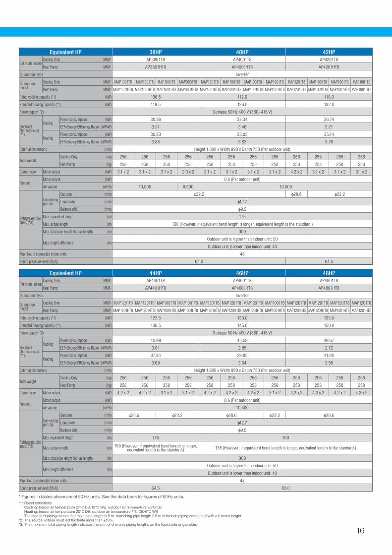
Equivalent HP 38HP 40HP 42HP
Set model name Cooling Only MMY- AP3801T8 AP4001T8 AP4201T8
Heat Pump MMY- AP3801HT8 AP4001HT8 AP4201HT8
Outdoor unit type Inverter
Outdoor unit model
Cooling Only MMY- MAP1001T8 MAP1001T8 MAP1001T8 MAP0801T8 MAP1001T8 MAP1001T8 MAP1001T8 MAP1001T8 MAP1201T8 MAP1001T8 MAP1001T8 MAP1001T8
Heat Pump MMY- MAP1001HT8 MAP1001HT8 MAP1001HT8 MAP0801HT8 MAP1001HT8 MAP1001HT8 MAP1001HT8 MAP1001HT8 MAP1201HT8 MAP1001HT8 MAP1001HT8 MAP1001HT8
Rated cooling capacity (*1) (kW) 106.5 112.0 118.0
Standard heating capacity (*1) (kW) 119.5 126.5 132.0
Power supply (*2) 3-phase 50 Hz 400 V (380–415 V)
Electrical characteristics (*1)
CoolingPower consumption (kW) 30.36 32.34 36.74
EER (Energy Efficiency Ratio) (kW/kW) 3.51 3.46 3.21
HeatingPower consumption (kW) 30.83 33.05 35.14
EER (Energy Efficiency Ratio) (kW/kW) 3.88 3.83 3.76
External dimensions (mm) Height 1,800 x Width 990 x Depth 750 (Per outdoor unit)
Total weight Cooling Only (kg) 256 256 256 256 256 256 256 256 256 256 256 256
Heat Pump (kg) 258 258 258 258 258 258 258 258 258 258 258 258
Compressor Motor output (kW) 3.1 x 2 3.1 x 2 3.1 x 2 2.3 x 2 3.1 x 2 3.1 x 2 3.1 x 2 3.1 x 2 4.2 x 2 3.1 x 2 3.1 x 2 3.1 x 2
Fan unit Motor output (kW) 0.6 (Per outdoor unit)
Air volume (m3/h) 10,500 9,900 10,500
Refrigerant pipe spec. (*3)
Connecting port dia.
Gas side (mm) φ22.2 φ28.6 φ22.2
Liquid side (mm) φ12.7
Balance side (mm) φ9.5
Max. equivalent length (m) 175
Max. actual length (m) 150 (However, if equivalent bend length is longer, equivalent length is the standard.)
Max. total pipe length (Actual length) (m) 300
Max. height difference (m)Outdoor unit is higher than indoor unit: 50
Outdoor unit is lower than indoor unit: 40
Max. No. of connected indoor units 48
Sound pressure level (dB(A)) 64.0 64.5
Equivalent HP 44HP 46HP 48HP
Set model name Cooling Only MMY- AP4401T8 AP4601T8 AP4801T8
Heat Pump MMY- AP4401HT8 AP4601HT8 AP4801HT8
Outdoor unit type Inverter
Outdoor unit model
Cooling Only MMY- MAP1201T8 MAP1201T8 MAP1001T8 MAP1001T8 MAP1201T8 MAP1201T8 MAP1201T8 MAP1001T8 MAP1201T8 MAP1201T8 MAP1201T8 MAP1201T8
Heat Pump MMY- MAP1201HT8 MAP1201HT8 MAP1001HT8 MAP1001HT8 MAP1201HT8 MAP1201HT8 MAP1201HT8 MAP1001HT8 MAP1201HT8 MAP1201HT8 MAP1201HT8 MAP1201HT8
Rated cooling capacity (*1) (kW) 123.5 130.0 135.0
Standard heating capacity (*1) (kW) 138.5 145.0 150.0
Power supply (*2) 3-phase 50 Hz 400 V (380–415 V)
Electrical characteristics (*1)
CoolingPower consumption (kW) 40.99 45.59 49.67
EER (Energy Efficiency Ratio) (kW/kW) 3.01 2.85 2.72
HeatingPower consumption (kW) 37.36 39.85 41.80
EER (Energy Efficiency Ratio) (kW/kW) 3.69 3.64 3.59
External dimensions (mm) Height 1,800 x Width 990 x Depth 750 (Per outdoor unit)
Total weight Cooling Only (kg) 256 256 256 256 256 256 256 256 256 256 256 256
Heat Pump (kg) 258 258 258 258 258 258 258 258 258 258 258 258
Compressor Motor output (kW) 4.2 x 2 4.2 x 2 3.1 x 2 3.1 x 2 4.2 x 2 4.2 x 2 4.2 x 2 3.1 x 2 4.2 x 2 4.2 x 2 4.2 x 2 4.2 x 2
Fan unit Motor output (kW) 0.6 (Per outdoor unit)
Air volume (m3/h) 10,500
Refrigerant pipe spec. (*3)
Connecting port dia.
Gas side (mm) φ28.6 φ22.2 φ28.6 φ22.2 φ28.6
Liquid side (mm) φ12.7
Balance side (mm) φ9.5
Max. equivalent length (m) 175 160
Max. actual length (m) 150 (However, if equivalent bend length is longer, equivalent length is the standard.) 135 (However, if equivalent bend length is longer, equivalent length is the standard.)
Max. total pipe length (Actual length) (m) 300
Max. height difference (m)Outdoor unit is higher than indoor unit: 50
Outdoor unit is lower than indoor unit: 40
Max. No. of connected indoor units 48
Sound pressure level (dB(A)) 64.5 65.0
16

Basic Outdoor Unit
Connecting 2 to 4 Units
(Unit: mm)
(Unit: mm)
For piping and wiring parts, see the basic outdoor unit.Install outdoor units in order of capacity.
4020 (Four connections)
1800
1640
700
88
990 990 990 99020 or more 20 or more 20 or more
A −15×20 (long hole)
750
755
(Incl
udin
g at
tach
ed le
gs)
Anc
hor b
olt p
itch
790
700 700
Anchor bolt pitch Anchor bolt pitch
(310) (310) 700 700
Anchor bolt pitch Anchor bolt pitch
(310)
165
2000 (Two connections)
3010 (Three connections)
AP1401HT8 AP1601HT8 AP1801HT8 AP2001HT8 AP2211HT8 AP2411HT8
AP2201HT8
Two connections
Three connections
MMY-
MMY-
AP3201HT8Four connections MMY-
AP2401HT8 AP2601HT8 AP2801HT8 AP3001HT8 AP3211HT8 AP3411HT8
AP3401HT8 AP3601HT8 AP3801HT8 AP4001HT8 AP4201HT8 AP4401HT8 AP4601HT8 AP4801HT8
AP3611HT8SMMS (Heat pump)
Two connections
Three connections
Four connections
A
8
12
16
755
Anc
hor
bol
t pitc
h
700
Anchor bolt pitch
Bottom panel contact part Base
Base8080
630
610
100
100
Base bolt position
(Incl
udin
g at
tach
ed le
gs)
990
4-15×20 (long hole)Z part
750
755
Anc
hor b
olt p
itch
790
700
Anchor bolt pitch
Piping front view / Hole details for wiring
Knock-out hole for routing electrical wires ( 48)
Knock-out hole for routing control wires ( 27)
88115
230225
155 215
205*
8813
5
(0801HT8 · 1001HT8 · 1201HT8)
280
MAP (0501HT8 · 0601HT8)
Detail of hole for routing bottom pipe (flat view)
Z view
140
13612
564
67
2052
173
55
Balanced pipe connecting port ( 9.5)
Refrigerant pipe connecting port A (Gas side)
Refrigerant pipe connecting port B (Liquid side)
241
Refrigerant pipe connecting port A (Gas side)
Refrigerant pipe connecting port B (Liquid side)
1800
1640
700
88
5002-60×150 square hole(Square holes for freight handling)
165
Balanced pipe connecting port ( 9.5)
ZZ
SMMS (Heat pump) MMY- MAP0501HT8 MAP0601HT8 MAP0801HT8 MAP1001HT8 MAP1201HT8
MMY-
MAP0501HT8
MAP0601HT8
MAP0801HT8
MAP1001HT8
MAP1201HT8
Pipe diameters
A
15.9
19.1
22.2
22.2
28.6
B
9.5
9.5
12.7
12.7
12.7*: Cut position for L-shaped pipe
when connecting gas pipes
External view of outdoor unit
17

Indoor unit range
4-wayair dischargecassette type
Compact 4-waycassette
(600 × 600) type
2-wayair dischargecassette type
1-wayair dischargecassette type
Concealed ducttype
Concealed ducthigh static
pressure typeSlim duct type*2
Cooling capacity
(HP equivalent)
007 type 2.2 kW (0.8HP) MMU-AP0071MH MMU-AP0071WH MMU-AP0071YH MMD-AP0071BH MMD-AP0071SPH
009 type 2.8 kW (1HP) MMU-AP0092H MMU-AP0091MH MMU-AP0091WH MMU-AP0091YH MMD-AP0091BH MMD-AP0091SPH
012 type 3.6 kW (1.25HP) MMU-AP0122H MMU-AP0121MH MMU-AP0121WH MMU-AP0121YH MMD-AP0121BH MMD-AP0121SPH
015 type 4.5 kW (1.7HP) MMU-AP0152H MMU-AP0151MH MMU-AP0151WH MMU-AP0152SH MMD-AP0151BH MMD-AP0151SPH
018 type 5.6 kW (2HP) MMU-AP0182H MMU-AP0181MH MMU-AP0181WH MMU-AP0182SH MMD-AP0181BH MMD-AP0181H MMD-AP0181SPH
024 type 7.1 kW (2.5HP) MMU-AP0242H MMU-AP0241WH MMU-AP0242SH MMD-AP0241BH MMD-AP0241H
027 type 8.0 kW (3HP) MMU-AP0272H MMU-AP0271WH MMD-AP0271BH MMD-AP0271H
030 type 9.0 kW (3.2HP) MMU-AP0302H MMU-AP0301WH MMD-AP0301BH
036 type 11.2 kW (4HP) MMU-AP0362H MMD-AP0361BH MMD-AP0361H
048 type 14.0 kW (5HP) MMU-AP0482H MMU-AP0481WH*1 MMD-AP0481BH MMD-AP0481H
056 type 16.0 kW (6HP) MMU-AP0562H MMD-AP0561BH
072 type 22.4 kW (8HP) MMD-AP0721H
096 type 28.0 kW (10HP) MMD-AP0961H
“-K” is appended to model number end in the Korea market*1 China market only*2 (SPH-C) China market only, (SH-C) Drain pump connection not possible/China market only*3 European market only
Ceiling typeHigh wall type
1 seriesHigh wall type
2 series*3
Floor standingconcealed type
Floor standing cabinet type
Floor standingtype
Fresh air intake indoor unit type
Cooling capacity
(HP equivalent)
007 type 2.2 kW (0.8HP) MMK-AP0071H MMK-AP0072H MML-AP0071BH MML-AP0071H
009 type 2.8 kW (1HP) MMK-AP0091H MMK-AP0092H MML-AP0091BH MML-AP0091H
012 type 3.6 kW (1.25HP) MMK-AP0121H MMK-AP0122H MML-AP0121BH MML-AP0121H
015 type 4.5 kW (1.7HP) MMC-AP0151H MMK-AP0151H MML-AP0151BH MML-AP0151H MMF-AP0151H
018 type 5.6 kW (2HP) MMC-AP0181H MMK-AP0181H MML-AP0181BH MML-AP0181H MMF-AP0181H
024 type 7.1 kW (2.5HP) MMC-AP0241H MMK-AP0241H MML-AP0241BH MML-AP0241H MMF-AP0241H
027 type 8.0 kW (3HP) MMC-AP0271H MMF-AP0271H
030 type 9.0 kW (3.2HP)
036 type 11.2 kW (4HP) MMC-AP0361H MMF-AP0361H
048 type 14.0 kW (5HP) MMC-AP0481H MMF-AP0481H MMD-AP0481HFE
056 type 16.0 kW (6HP) MMF-AP0561H
072 type 22.4 kW (8HP) MMD-AP0721HFE
096 type 28.0 kW (10HP) MMD-AP0961HFE
New High wall type 3 series
Appearance
Model number To be decided
Coming soon
18
MMU-AP0092H to MMU-AP0562H
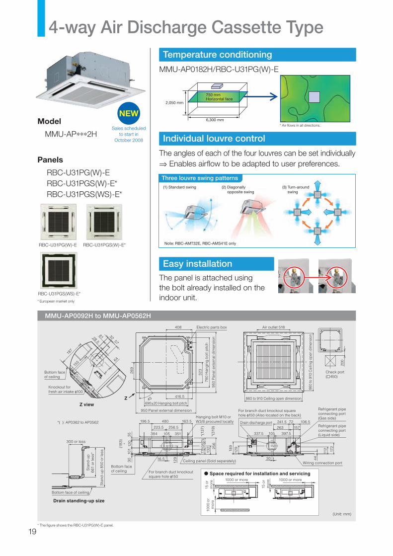
4-way Air Discharge Cassette Type
NEWModel
MMU-AP∗∗∗2H
Panels
RBC-U31PG(W)-ERBC-U31PGS(W)-E*RBC-U31PGS(WS)-E*
Temperature conditioning
MMU-AP0182H/RBC-U31PG(W)-E
23 28
2,050 mm
4,500 mm
6,300 mm
Horizontal face750 mm
Mode: coolingLouvre position: horizontalFan speed : Hi
Vertical face
( C)
Individual louvre control
The angles of each of the four louvres can be set individually⇒ Enables airflow to be adapted to user preferences.
Easy installation
The panel is attached using the bolt already installed on the indoor unit.
(1) Standard swing
Note: RBC-AMT32E, RBC-AMS41E only
(2) Diagonally opposite swing
(3) Turn-around swing
Three louvre swing patterns
Sales scheduled to start in
October 2008
(Unit: mm)
RBC-U31PG(W)-E
RBC-U31PGS(WS)-E*
RBC-U31PGS(W)-E*
155
28.5
6157
6418
7
32
Bottom face of ceiling
Knockout for fresh air intake 100
300 or less
Sta
nd-u
p6
61 o
r le
ss*
Sta
nd-u
p 8
50 o
r le
ss
Bottom face of ceiling
*( ): AP0362 to AP0562
Bottom face of ceiling
Ceiling panel (Sold separately)
Hanging bolt M10 or W3/8 procured locally
For branch duct knockout square hole 150
129
132 25
6
30
101
16.5
351
480
256.5
196.5
38435 105
223.5
163.5
7774
105
(18
3) *12
0
*(13
7)
*(31
9)
Refrigerant pipe connecting port (Gas side)
Refrigerant pipe connecting port (Liquid side)
Drain discharge port
For branch duct knockout square hole 150 (Also located on the back)
241.5
263
397.5
129
189
337.5
30
105
72 106.5
172
112
44
157
Wiring connection port
1000 or more 1000 or more
15 o
r m
ore
15 o
r m
ore
100
0 or
m
ore
860 to 910 Ceiling open dimension
860
to 9
10 C
eilin
g op
en d
imen
sion
Air outlet 518
Drain standing-up size
Space required for installation and servicing
Z view45�
950
Pan
el e
xter
nal d
imen
sion
780
Han
gin
g b
olt p
itch
416.5
408
690±20 Hanging bolt pitch
950 Panel external dimension
269
323
Electric parts box
Z
200
Check port( 450)
* European market only
* The figure shows the RBC-U31PG(W)-E panel.
* Air flows in all directions.
19

Model name MMU- AP0092H AP0122H AP0152H AP0182H AP0242H AP0272H AP0302H AP0362H AP0482H AP0562H
Cooling/Heating capacity*1 (kW) 2.8/3.2 3.6/4.0 4.5/5.0 5.6/6.3 7.1/8.0 8.0/9.0 9.0/10.0 11.2/12.5 14.0/16.0 16.0/18.0
Electricalcharacteristics
Power requirements 1-phase 50 Hz 230 V (220–240 V)/1-phase 60 Hz 220 V (Separate power supply for indoor units required.)
Power consumption 50 Hz/60 Hz (kW)
0.021/0.021 0.023/ 0.023
0.026/0.026 0.036/0.036 0.043/
0.0430.088/0.088
0.112/0.112
0.112/0.112
Appearance (Ceiling panel) Model RBC-U31PG(W)-E/RBC-U31PGS(W)-E*/RBC-U31PGS(WS)-E*
Externaldimensions:Main unit(Ceiling panel)*
Height (mm) 256 (30)* 319 (30)*
Width (mm) 840 (950)*
Depth (mm) 840 (950)*
Total weight: Main unit (Ceiling panel)* (kg) 18 (4)* 20 (4)* 25 (4)*
Fan unit
Standard air flow (High/Mid/Low) (m3/h)
800/730/680 930/830/790
1050/ 920/800 1290/920/800 1320/
1110/8501970/
1430/10702130/
1430/11302130/
1520/1230
Motor output (W) 14 20 68 72
Connecting pipe
Gas side (mm) φ9.5 φ12.7 φ15.9
Liquid side (mm) φ6.4 φ9.5
Drain port (nominal dia.) 25 (Polyvinyl chloride tube)
Sound pressure level*2 (High/Mid/Low) (dB(A))
30/29/27 31/29/27 32/29/27 35/31/28 38/33/30 43/38/32 46/38/33 46/40/33
* Preliminary* Figures in parentheses are for ceiling panels.*1 This reference piping consists of 5 m of main piping and 2.5 m of branch piping connected at the same height level.*2 The actual values in an external operating environment are generally higher than the indicated values due to the contribution from ambient noise.
4-way Air Discharge Cassette Type
Options
Air discharge direction kit
TCB-BC1602UE
Fresh air inlet box
TCB-GB1602UE
Ceiling panel
RBC-U31PG(W)-ERBC-U31PGS(W)-E*RBC-U31PGS(WS)-E*
Auxiliary fresh air flange
TCB-FF101URE2
Fresh air and filter chamberTCB-GFC1602UE
Spacer for height adjustment
TCB-SP1602UE
* European market only
20
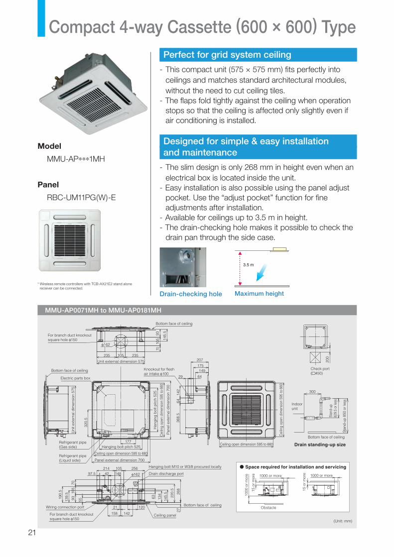
Perfect for grid system ceiling
- This compact unit (575 × 575 mm) fits perfectly into ceilings and matches standard architectural modules, without the need to cut ceiling tiles.
- The flaps fold tightly against the ceiling when operation stops so that the ceiling is affected only slightly even if air conditioning is installed.
Designed for simple & easy installation and maintenance
- The slim design is only 268 mm in height even when an electrical box is located inside the unit.
- Easy installation is also possible using the panel adjust pocket. Use the “adjust pocket” function for fine adjustments after installation.
- Available for ceilings up to 3.5 m in height.- The drain-checking hole makes it possible to check the
drain pan through the side case.
Model
MMU-AP∗∗∗1MH
Panel
RBC-UM11PG(W)-E
Compact 4-way Cassette (600 × 600) Type
MMU-AP0071MH to MMU-AP0181MH
3.5 m
Maximum heightDrain-checking hole
(Unit: mm)
* Wireless remote controllers with TCB-AX21E2 stand alone receiver can be connected.
For branch duct knockout square hole 150
Knockout for flesh air intake 100
Pan
el e
xter
nal d
imen
sion
700
Cei
ling
open
dim
ensi
on 5
95 to
660
Han
gin
g b
olt p
itch
525
Bottom face of ceiling
Electric parts box
Unit external dimension 575
177
Bottom face of ceiling
235 235207
29
175149
64
70
142
6436
8.5
320.
5
Refrigerant pipe (Gas side)
97.5
7010
5
55
63 134
145.
5
220.
5
268
27
93139.
5
190.
5
214
162
25610542
142
120
158
21
148
Refrigerant pipe (Liquid side)
Wiring connection port
Uni
t ext
erna
l dim
ensi
on 5
75
Hanging bolt pitch 525
Ceiling open dimension 595 to 660
Panel external dimension 700
Hanging bolt M10 or W3/8 procured locally
Drain discharge port
Bottom face of ceiling
Ceiling panel
105
93
145.
5
105
162
For branch duct knockout square hole 150
Cei
ling
open
dim
ensi
on 5
95 to
660
1000
or
mor
e
15 o
r m
ore
15 o
r m
ore1000 or more 1000 or more
Obstacle
Ceiling open dimension 595 to 660
Bottom face of ceiling
Stan
d-up
629.
5 or
less
Stan
d-up
850
or l
ess
300
Drain standing-up size
Space required for installation and servicing
Indoor unit
200
Check port( 450)
21

Options
Auxiliary fresh air flange
TCB-FF101URE2
Ceiling panel
RBC-UM11PG(W)-E
Model name MMU- AP0071MH AP0091MH AP0121MH AP0151MH AP0181MH
Cooling/Heating capacity*1 (kW) 2.2/2.5 2.8/3.2 3.6/4.0 4.5/5.0 5.6/6.3
Electricalcharacteristics
Power requirements 1-phase 50 Hz 230 V (220–240 V)/1-phase 60 Hz 220 V (Separate power supply for indoor units required.)
Power consumption 50 Hz/60 Hz (kW)
0.034/0.034 0.036/0.036 0.038/0.038 0.041/0.041 0.052/0.052
Appearance (Ceiling panel) Model RBC-UM11PG(W)-E
Externaldimensions:Main unit(Ceiling panel)*
Height (mm) 268 (27)*
Width (mm) 575 (700)*
Depth (mm) 575(700)*
Total weight: Main unit (Ceiling panel)* (kg) 17 (3)*
Fan unit
Standard air flow (High/Mid/Low) (m3/h)
552/462/378 570/468/378 594/504/402 660/552/468 762/642/522
Motor output (W) 60
Connecting pipe
Gas side (mm) φ9.5 φ12.7
Liquid side (mm) φ6.4
Drain port (nominal dia.) 25 (Polyvinyl chloride tube)
Sound pressure level*2 (High/Mid/Low) (dB(A))
36/32/28 37/33/28 37/33/29 40/35/30 44/39/34
* Figures in parentheses are for ceiling panels.*1 This reference piping consists of 5 m of main piping and 2.5 m of branch piping connected at the same height level.*2 The actual values in an external operating environment are generally higher than the indicated values due to the contribution from ambient noise.
Compact 4-way Cassette (600 × 600) Type
22
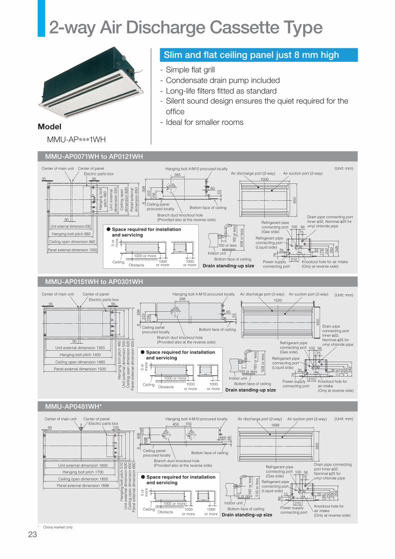
MMU-AP0151WH to AP0301WH
MMU-AP0481WH*
MMU-AP0071WH to AP0121WH
Slim and flat ceiling panel just 8 mm high
- Simple flat grill- Condensate drain pump included- Long-life filters fitted as standard- Silent sound design ensures the quiet required for the
office- Ideal for smaller rooms
2-way Air Discharge Cassette Type
Model
MMU-AP∗∗∗1WH
* China market only
(Unit: mm)
(Unit: mm)
(Unit: mm)
Space required for installation and servicing
Electric parts box
53 60
30
95 35 265
222 39
8
156
8
Center of main unit Center of panel
Unit external dimension 830
Hanging bolt pitch 880
Ceiling open dimension 960
Panel external dimension 1000
Han
gin
g b
olt
pitc
h 48
0
Uni
t ext
erna
ld
imen
sion
550
Cei
ling
op
end
imen
sion
620
Pan
el e
xter
nal
dim
ensi
on 6
50
Hanging bolt 4-M10 procured locally
Branch duct knockout hole (Provided also at the reverse side)
Ceiling panelprocured locally Bottom face of ceiling
200
1000
650
Air suction port (2-way)Air discharge port (2-way)
1000 or more
Ceiling 1000or more
5 o
r m
ore
1000or moreObstacle
508
or le
ss
160
or le
ss
100 or less
Bottom face of ceiling
Indoor unit
Drain standing-up size
10075 56
Power supply connecting port
178
242
282
348
35
78
35
210
Refrigerant pipe connecting port (Gas side)
Refrigerant pipe connecting port (Liquid side)
Drain pipe connecting port Inner 32, Nominal 25 for vinyl chloride pipe
Knockout hole for air intake (Only at reverse side)
ø150150
Space required for installation and servicing
Drain standing-up size
Branch duct knockout hole (Provided also at the reverse side)
35 95
30
53 200
60
295
222 39
8
156
8
Center of main unit Center of panelElectric parts box
Unit external dimension 1350
Hanging bolt pitch 1400
Ceiling open dimension 1480
Panel external dimension 1520
Han
gin
g b
olt p
itch
480
Uni
t ext
erna
l dim
ensi
on 5
50C
eilin
g o
pen
dim
ensi
on 6
20P
anel
ext
erna
l dim
ensi
on 6
50
Hanging bolt 4-M10 procured locally
Ceiling panelprocured locally
Bottom face of ceiling
650
Air suction port (2-way)Air discharge port (2-way)
1000 or more
Ceiling
5 or
m
ore
1000or more
1000or moreObstacle
508
or le
ss
160
or le
ss
100 or less
Bottom face of ceilingIndoor unit
100
1520
75 56
Power supply connecting port
178
242
282
348
35
78
35
210
Refrigerant pipe connecting port (Gas side)
Refrigerant pipe connecting port (Liquid side)
Drain pipe connecting port Inner 32, Nominal 25 for vinyl chloride pipe
Knockout hole for air intake (Only at reverse side)
ø150150
Space required for installation and servicing
Drain standing-up size
Electric parts box
95
230
406
60
8
166 68
455 150 5 105
Center of main unit Center of panel
Unit external dimension 1650
Hanging bolt pitch 1700
Ceiling open dimension 1850
Panel external dimension 1898
Hanging bolt 4-M10 procured locally
Ceiling panelprocured locally
Branch duct knockout hole (Provided also at the reverse side)
Bottom face of ceiling
200
200
1000 or moreCeiling 1000
or more1000
or more
5 or
m
ore
Obstacle
Han
gin
g b
olt p
itch
510
Uni
t ext
erna
l dim
ensi
on 6
20C
eilin
g o
pen
dim
ensi
on 6
50P
anel
ext
erna
l dim
ensi
on 6
80
516
or le
ss
160
or le
ss
100 or less
Bottom face of ceiling
Indoor unit
Air suction port (2-way)Air discharge port (2-way)
680
1898
10075 56
Power supply connecting port
186
250
290
356
15
86
15
210
Refrigerant pipe connecting port (Gas side)
Refrigerant pipe connecting port (Liquid side)
Drain pipe connecting port Inner 32, Nominal 25 for vinyl chloride pipe
Knockout hole for air intake (Only at reverse side)
ø150150
23

Options
* Figures in parentheses are for ceiling panels.*1 This reference piping consists of 5 m of main piping and 2.5 m of branch piping connected at the same height level.*2 The actual values in an external operating environment are generally higher than the indicated values due to the contribution from ambient noise.*3 China market only
2-way Air Discharge Cassette Type
Model name MMU- AP0071WH AP0091WH AP0121WH AP0151WH AP0181WH AP0241WH AP0271WH AP0301WH AP0481WH*3
Cooling/Heating capacity*1 (kW) 2.2/2.5 2.8/3.2 3.6/4.0 4.5/5.0 5.6/6.3 7.1/8.0 8.0/9.0 9.0/10.0 14.0/16.0
Electricalcharacteristics
Power requirements 1-phase 50 Hz 230 V (220–240 V)/1-phase 60 Hz 220 V (Separate power supply for indoor units required.) 1-phase 50 Hz 220 V
Power consumption 50 Hz/60 Hz (kW)
0.070/0.070 0.072/0.076 0.105/0.115 0.106/0.123 0.250
Appearance (Ceiling panel) Model RBC-UW136PG RBC-UW266PG RBC-UW466PG
Externaldimensions:Main unit(Ceiling panel)*
Height (mm) 398 (8)* 406 (8)
Width (mm) 830 (1000)* 1350 (1520)* 1650 (1898)
Depth (mm) 550 (650)* 620 (680)
Total weight: Main unit (Ceiling panel)* (kg) 33 (8)* 44 (11)* 48 (11)* 52 (18)
Fan unit
Standard air flow (High/Mid/Low) (m3/h)
570/510/450 780/700/600 1140/960/720 1260/ 1140/960
1920/1500/1050
Motor output (W) 53 39 53 92
Connecting pipe
Gas side (mm) φ9.5 φ12.7 φ15.9
Liquid side (mm) φ6.4 φ9.5
Drain port (nominal dia.) 25 (Polyvinyl chloride tube)
Sound pressure level*2 (High/Mid/Low) (dB(A))
34/32/30 35/33/30 38/35/33 40/37/34 45/42/39
Ceiling panel
RBC-UW136PGRBC-UW266PGRBC-UW466PG
24
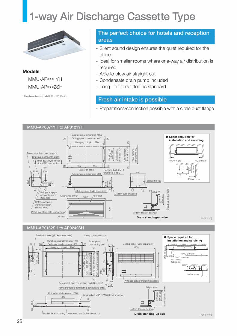
The perfect choice for hotels and reception areas
- Silent sound design ensures the quiet required for the office
- Ideal for smaller rooms where one-way air distribution is required
- Able to blow air straight out- Condensate drain pump included- Long-life filters fitted as standard
Fresh air intake is possible
- Preparations/connection possible with a circle duct flange
1-way Air Discharge Cassette Type
MMU-AP0071YH to AP0121YH
MMU-AP0152SH to AP0242SH
Models
MMU-AP∗∗∗1YH
MMU-AP∗∗∗2SH
(Unit: mm)
(Unit: mm)
Space required for installation and servicing
Drain standing-up size
Ceiling panel (Sold separately)
1050
470
Han
ging
bol
t pi
tch
330
Uni
t ext
erna
l di
men
sion
400
Cei
ling
op
en
dim
ensi
on 4
30
Panel external dimension 1050
Hanging bolt pitch 890
Ceiling open dimension 1010 2020
2020150
100225
200
120
140 23
518
85
( )Drain pipe connecting port
Refrigerant pipe connecting port (Gas side)
Refrigerant pipe connecting port (Liquid side)
Power supply connecting port
Inner 32 vinyl chloride pipe VP25 connection
400
Support metal
Unit external dimension 850
395 455 50110
Center of panel Hanging bolt 4-M10 procured locally
Bottom face of ceilingAir outlet
Air inlet
Discharge louver
Panel mounting hole 5 positions
100 or more
200 or more
245
or m
ore
100 or more
Bottom face of ceiling
100 or less
Sta
nd-u
p 3
50 o
r le
ss
Stan
d-up
150
or le
ss
Pan
el e
xter
nal
dim
ensi
on 4
70
Space required for installation and servicing
Refrigerant pipe connecting port (Gas side)
Refrigerant pipe connecting port (Liquid side)
Ceiling panel (Sold separately)
1230
800
Wireless sensor mounting section
Pane
l ext
erna
ldim
ensi
on 8
00
Han
ging
bolt
pitc
h 47
510
013
5Un
it ext
erna
l dim
ensio
n 71
0
Cei
ling
open
dim
ensi
on 7
60
220
Panel external dimension 1230
Hanging bolt pitch 1060Ceiling open dimension 1190 20
20
20
20
7673
.4
2020
093
Bottom face of ceiling Knockout hole for front blow out
Hanging bolt M10 or W3/8 local arrange
Fresh air intake ( 92 knockout hole)
112
112
122
233
154
80
94
Drain pipe connecting port
216
6043
Wiring connection port
72
Unit external dimension 1000
706
Bottom face of ceiling
140 or less
Sta
nd-u
p 8
50 o
r le
ss20
5 or
mor
e
Ceiling1000 or more
Obstacle
200 or more
1000 or more
Drain standing-up size
Stan
d-up
696
or le
ss
* The photo shows the MMU-AP∗∗∗2SH Series.
25
Options
* Figures in parentheses are for ceiling panels.*1 This reference piping consists of 5 m of main piping and 2.5 m of branch piping connected at the same height level.*2 The actual values in an external operating environment are generally higher than the indicated values due to the contribution from ambient noise.
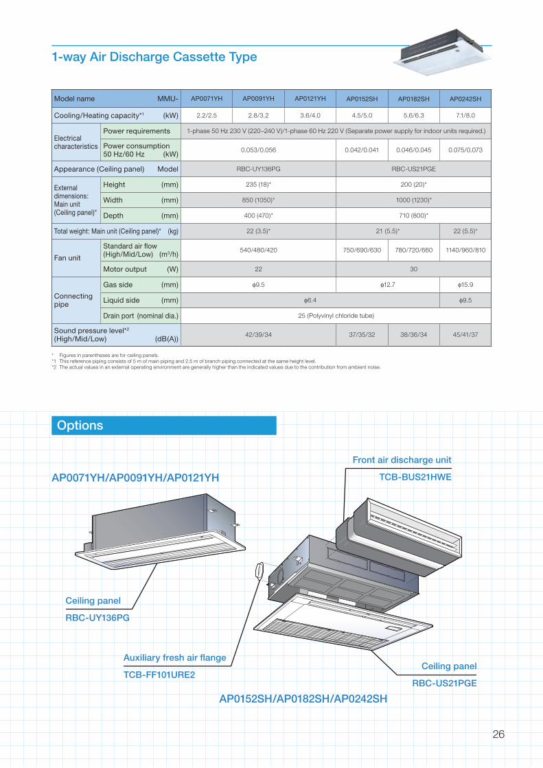
1-way Air Discharge Cassette Type
Model name MMU- AP0071YH AP0091YH AP0121YH AP0152SH AP0182SH AP0242SH
Cooling/Heating capacity*1 (kW) 2.2/2.5 2.8/3.2 3.6/4.0 4.5/5.0 5.6/6.3 7.1/8.0
Electricalcharacteristics
Power requirements 1-phase 50 Hz 230 V (220–240 V)/1-phase 60 Hz 220 V (Separate power supply for indoor units required.)
Power consumption 50 Hz/60 Hz (kW)
0.053/0.056 0.042/0.041 0.046/0.045 0.075/0.073
Appearance (Ceiling panel) Model RBC-UY136PG RBC-US21PGE
Externaldimensions:Main unit(Ceiling panel)*
Height (mm) 235 (18)* 200 (20)*
Width (mm) 850 (1050)* 1000 (1230)*
Depth (mm) 400 (470)* 710 (800)*
Total weight: Main unit (Ceiling panel)* (kg) 22 (3.5)* 21 (5.5)* 22 (5.5)*
Fan unit
Standard air flow (High/Mid/Low) (m3/h)
540/480/420 750/690/630 780/720/660 1140/960/810
Motor output (W) 22 30
Connecting pipe
Gas side (mm) φ9.5 φ12.7 φ15.9
Liquid side (mm) φ6.4 φ9.5
Drain port (nominal dia.) 25 (Polyvinyl chloride tube)
Sound pressure level*2 (High/Mid/Low) (dB(A))
42/39/34 37/35/32 38/36/34 45/41/37
Ceiling panel
RBC-UY136PG
Auxiliary fresh air flange
TCB-FF101URE2Ceiling panel
RBC-US21PGE
Front air discharge unit
TCB-BUS21HWEAP0071YH/AP0091YH/AP0121YH
AP0152SH/AP0182SH/AP0242SH
26

Model
MMD-AP∗∗∗1BH
Features
- Allows complete design flexibility- Full range of filters to enhance indoor air quality- Fresh air intake is possible
High static pressure
External static pressure can be raised as high as 110 Pa, so that all areas of the room can be reached for even temperature distribution, no matter how complex the layout.
High-lift drain pump
The flexible piping layout is made possible by an optionally available drain pump kit that raises the drain piping up to 27 cm from the drain port.
Concealed Duct Type
MMD-AP0071BH to AP0561BH
(Unit: mm)
125 knockout hole for taking-in air
10- 4 tapping screw 160
Panel C, L
130
101
26 power supply, remote controller wire exit portCeiling open dimension D
Air suction E
B
C 142
70 to
270
240
Drain pipe connecting port (Inner 32 vinyl chloride pipe VP25 connection)
Hanging bolt 4-M10 procured locally
Refrigerant pipe connecting port (Liquid side)
Refrigerant pipe connecting port (Gas side)
Unit external dimension 800
Hanging bolt pitch 700
Hanging bolt pitch A ±7.5
44
50
498
5941
4025
49
(Whe
n at
tach
ing
dire
ctly
)
Ceiling opening 470
393
196
50 50 24313
1
41
215
Air outlet Air inlet
638
100 or less550
or le
ss 271
or le
ss
Space required for installation and servicingDrain standing-up size
AP0071BH, AP0091BH, AP0121BH
AP0151BH, AP0181BH
AP0241BH, AP0271BH, AP0301BH
AP0361BH, AP0481BH, AP0561BH
Model MMD-
616
766
1066
1416
550
700
1000
1350
350
500
800
1150
600
750
1050
1400
470
620
920
1270
A B D EC
Air outlet
Checkport B450
Checkport A450
Air filter700 for maintenance of air filter 700 for maintenance of air filter
Ceiling opening part
(150)
300
Be sure to place a check port A at the position indicated in the figure for maintenance of the equipment.
27

*1 This reference piping consists of 5 m of main piping and 2.5 m of branch piping connected at the same height level.*2 The actual values in an external operating environment are generally higher than the indicated values due to the contribution from ambient noise.
Concealed Duct Type
Model name MMD- AP0071BH AP0091BH AP0121BH AP0151BH AP0181BH AP0241BH AP0271BH AP0301BH AP0361BH AP0481BH AP0561BH
Cooling/Heating capacity*1 (kW) 2.2/2.5 2.8/3.2 3.6/4.0 4.5/5.0 5.6/6.3 7.1/8.0 8.0/9.0 9.0/10.0 11.2/12.5 14.0/16.0 16.0/18.0
Electricalcharacteristics
Power requirements 1-phase 50 Hz 230 V (220–240 V)/1-phase 60 Hz 220 V (Separate power supply for indoor units required.)
Power consumption 50 Hz/60 Hz (kW)
0.033/0.033 0.039/0.039 0.050/ 0.050 0.060/0.060 0.071/
0.0710.107/ 0.107 0.128/0.128
Externaldimensions:Main unit
Height (mm) 320
Width (mm) 550 700 1000 1350
Depth (mm) 800
Total weight (kg) 28 32 43 55
Fan unit
Standard air flow (High/Mid/Low) (m3/h)
480/420/340 570/490/400
650/540/480
780/ 660/540 1140/990/870 1260/
1080/8701620/
1410/12001980/
1710/1490
Motor output (W) 120
External static pressure (factory setting) (Pa)
50 (4 mmAq)
External static pressure (Pa)
110 (10 mmAq)
Connecting pipe
Gas side (mm) φ9.5 φ12.7 φ15.9
Liquid side (mm) φ6.4 φ9.5
Drain port (nominal dia.) 25 (Polyvinyl chloride tube)
Sound pressure level*2 (High/Mid/Low) (dB(A))
30/28/26 31/29/27 32/30/28 33/31/29 34/32/29 36/34/32 36/34/32 (50Hz)38/36/32 (60Hz)
Options
High-efficiency filter 65TCB-UFM11BETCB-UFM21BETCB-UFM31BETCB-UFM41BE
High-efficiency filter 90TCB-UFH51BETCB-UFH61BETCB-UFH71BETCB-UFH81BE
High-efficiency filter 65TCB-UFM11BFCETCB-UFM21BFCE
High-efficiency filter 90TCB-UFH51BFCETCB-UFH61BFCE
Suction canvas
TCB-CA281BE, TCB-CA501BETCB-CA801BE, TCB-CA1401BE
Filter chamber
TCB-FC281BE, TCB-FC501BETCB-FC801BE, TCB-FC1401BE
Filter kit for undersideTCB-FK281BETCB-FK501BETCB-FK801BETCB-FK1401BE
Standard filter and filter frame
Ceiling panel
RBC-UD281PE(W)/RBC-UD501PE(W)RBC-UD801PE(W)/RBC-UD1401PE(W)E
Back cover
Filter guide
Air filter
28
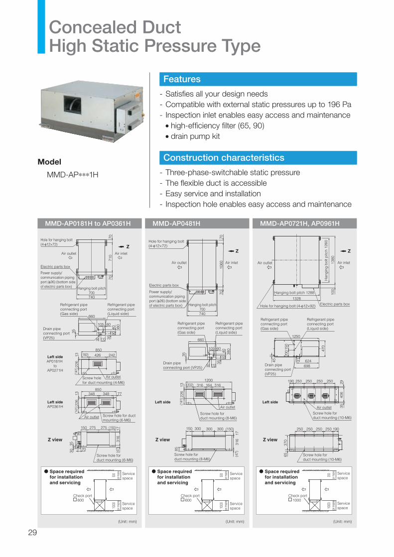
MMD-AP0181H to AP0361H MMD-AP0481H MMD-AP0721H, AP0961H
Features
- Satisfies all your design needs- Compatible with external static pressures up to 196 Pa- Inspection inlet enables easy access and maintenance •high-efficiency filter (65, 90) •drain pump kit
Construction characteristics
- Three-phase-switchable static pressure- The flexible duct is accessible- Easy service and installation- Inspection hole enables easy access and maintenance
Concealed Duct High Static Pressure Type
Model
MMD-AP∗∗∗1H
(Unit: mm) (Unit: mm) (Unit: mm)
Space required for installation and servicing
740
105
110
35
30 3540
9038
060
Hanging bolt pitch700
Air outlet
660
710
7070
Hole for hanging bolt (4- 12×72)
Electric parts box
Power supply/communication piping port ( 26) (bottom side of electric parts box)
Refrigerant pipe connecting port (Gas side)
Refrigerant pipe connecting port (Liquid side)
Drain pipe connecting port (VP25)
850242426(182)
348 77348
(141
) 226
13(1
41) 2
2613
Air outlet
Air outlet
Screw hole for duct mounting (6-M6)
Screw hole for duct mounting (4-M6)
Left sideAP0181H
toAP0271H
Left sideAP0361H
Air inlet
Screw hole for duct mounting (6-M6)
150 (150) 1731
6(4
7)
275 275
70
3530
850
Z
Z view
500
or mo
re10
00or
mor
e
Check port 600
Service space
Service space
Space required for installation and servicing
1200316164316(202)
(141
) 226
13
(47)
316
17
105
110
35
30
3540
9038
060
660
Refrigerant pipe connecting port (Gas side)
Refrigerant pipe connecting port(Liquid side)
Air outlet
Screw hole for duct mounting (8-M6)
(150)300300300150
Screw hole for duct mounting (8-M6)
Hole for hanging bolt(4- 12×72)
Electric parts box
740
Hanging bolt pitch700
1060
7070
Power supply/communication piping port ( 26) (bottom side of electric parts box)
Air inlet
Z
Air outlet
Drain pipe connecting port (VP25)
500
or mo
re10
00or
mor
e
Check port 600
Service space
Service space
85
Left side
Z view
Space required for installation and servicing
Left side
Z view
Z
Drain pipe connecting port (VP25)
Refrigerant pipe connecting port(Gas side)
1250
190 250 250 250 250
624698
31
470
406
3529
150
200
45
Air outlet
Screw hole for duct mounting (10-M6)
Screw hole for duct mounting (10-M6)
Refrigerant pipe connecting port(Liquid side)
250 190250 250 250
370
65
200
or mo
re10
00or
mor
e
Check port 1000
Service space
Service space
Han
gin
g b
olt p
itch
1260
1380
100
Electric parts boxHole for hanging bolt (4- 12×92)
1328
Hanging bolt pitch 1288
Air outlet Air inlet
29

*1 This reference piping consists of 5 m of main piping and 2.5 m of branch piping connected at the same height level.*2 The actual values in an external operating environment are generally higher than the indicated values due to the contribution from ambient noise.
Concealed Duct High Static Pressure Type
Model name MMD- AP0181H AP0241H AP0271H AP0361H AP0481H AP0721H AP0961H
Cooling/Heating capacity*1 (kW) 5.6/6.3 7.1/8.0 8.0/9.0 11.2/12.5 14.0/16.0 22.4/25.0 28.0/31.5
Electricalcharacteristics
Power requirements 1-phase 50 Hz 230 V (220–240 V)/1-phase 60 Hz 220 V (Separate power supply for indoor units required.)
Power consumption 50 Hz/60 Hz (kW)
0.184/0.198 0.299/0.385 0.368/0.450 0.414/0.490 1.200/1.540 1.260/1.610
Externaldimensions:Main unit
Height (mm) 380 470
Width (mm) 850 1200 1380
Depth (mm) 660 1250
Total weight (kg) 50 52 56 67 150
Fan unit
Standard air flow (High/Mid/Low) (m3/h)
900 1320 1600 2100 3600 4200
Motor output (W) 160 260 370×3
External static pressure (factory setting) (Pa)
137
External static pressure (Pa)
68.6 – 137 – 196
Connecting pipe
Gas side (mm) φ12.7 φ15.9 φ22.2
Liquid side (mm) φ6.4 φ9.5 φ12.7
Drain port (nominal dia.) 25 (male screw)
Sound pressure level*2 (High/Mid/Low) (dB(A))
37 40 49 50
Options
Filter chamber
TCB-FCY21DE, TCB-FCY31DE TCB-FCY51DE, TCB-FCY100DE
Long-life prefilter
TCB-PF1D-1ETCB-PF2D-1ETCB-PF3DE
Drain pump kit
TCB-DP31DETCB-DP32DE
High-efficiency filter 65TCB-UFM1D-1E, TCB-UFM2D-1E, TCB-UFM3DE
High-efficiency filter 90TCB-UFH5D-1E, TCB-UFH6D-1E, TCB-UFM7DE
30
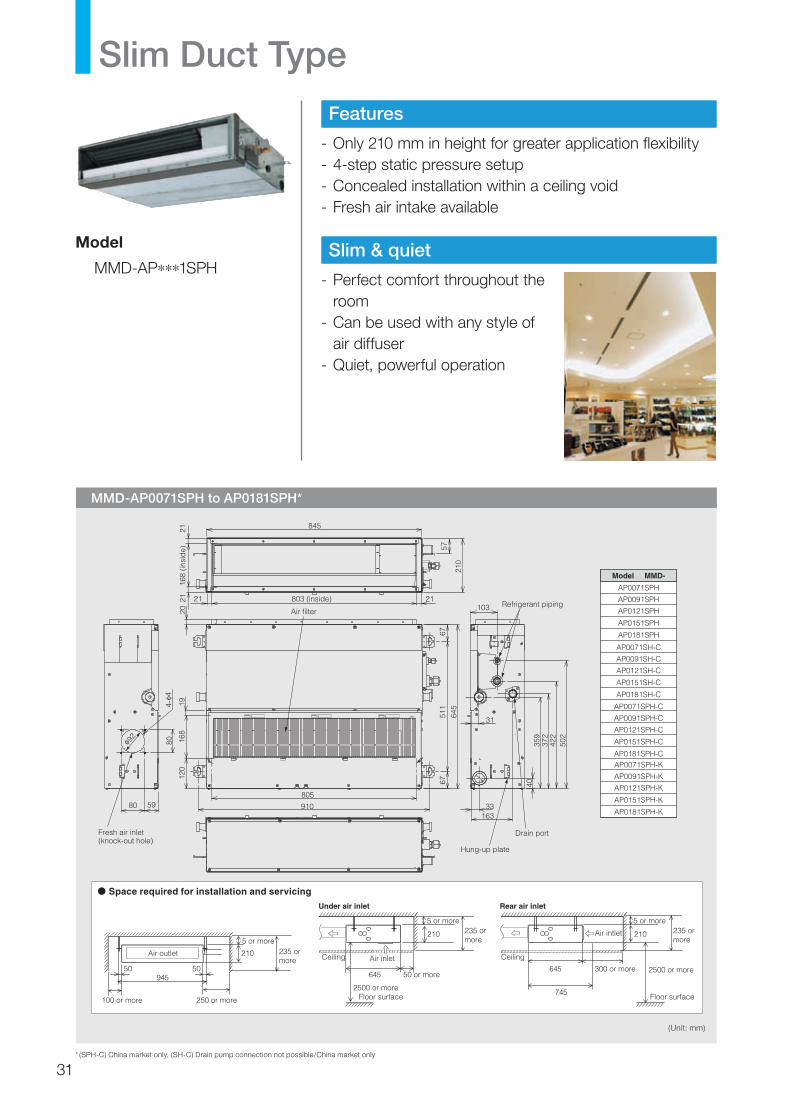
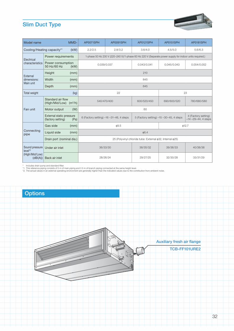
Slim Duct Type
MMD-AP0071SPH to AP0181SPH*
(Unit: mm)
Features
- Only 210 mm in height for greater application flexibility- 4-step static pressure setup- Concealed installation within a ceiling void- Fresh air intake available
Slim & quiet
- Perfect comfort throughout the room
- Can be used with any style of air diffuser
- Quiet, powerful operation
Model
MMD-AP∗∗∗1SPH
* (SPH-C) China market only, (SH-C) Drain pump connection not possible/China market only
Space required for installation and servicing
Model MMD-
5 or more
210
100 or more 250 or more
235 or more
Air outlet
50 50
5 or more 5 or more
50 or more
210 210235 or more
235 or more
2500 or moreFloor surface Floor surface
Air inletCeiling Ceiling
Under air inlet Rear air inlet
300 or more645
745
6459452500 or more
Air intlet
511
6767
910
372
359
422
502
103
31
16333
40
21803 (inside)
57
210
845
168
(insi
de)
2121
21
120
805
19
645
168
20 Air filterRefrigerant piping
Drain port
Hung-up plate
Fresh air inlet(knock-out hole)
80
5980
4-4
29
>ABS<
AP0071SPH
AP0091SPH
AP0121SPH
AP0151SPH
AP0181SPH
AP0071SPH-C
AP0091SPH-C
AP0121SPH-C
AP0151SPH-C
AP0181SPH-CAP0071SPH-K
AP0091SPH-K
AP0121SPH-K
AP0151SPH-K
AP0181SPH-K
AP0071SH-C
AP0091SH-C
AP0121SH-C
AP0151SH-C
AP0181SH-C
31
* Includes drain pump and standard filter.*1 This reference piping consists of 5 m of main piping and 2.5 m of branch piping connected at the same height level.*2 The actual values in an external operating environment are generally higher than the indicated values due to the contribution from ambient noise.
Slim Duct Type
Model name MMD- AP0071SPH AP0091SPH AP0121SPH AP0151SPH AP0181SPH
Cooling/Heating capacity*1 (kW) 2.2/2.5 2.8/3.2 3.6/4.0 4.5/5.0 5.6/6.3
Electricalcharacteristics
Power requirements 1-phase 50 Hz 230 V (220–240 V)/1-phase 60 Hz 220 V (Separate power supply for indoor units required.)
Power consumption 50 Hz/60 Hz (kW)
0.039/0.037 0.043/0.041 0.045/0.043 0.054/0.052
Externaldimensions:Main unit
Height (mm) 210
Width (mm) 845
Depth (mm) 645
Total weight (kg) 22 23
Fan unit
Standard air flow (High/Mid/Low) (m3/h)
540/470/400 600/520/450 690/600/520 780/680/580
Motor output (W) 60
External static pressure (factory setting) (Pa)
6 (Factory setting) –16 –31–46, 4 steps 5 (Factory setting) –15 –30–45, 4 steps 4 (Factory setting) –14 –29–44, 4 steps
Connecting pipe
Gas side (mm) φ9.5 φ12.7
Liquid side (mm) φ6.4
Drain port (nominal dia.) 25 (Polyvinyl chloride tube: External φ32, Internal φ25)
Sound pressure level*2 (High/Mid/Low)
(dB(A))
Under air inlet 36/33/30 38/35/32 39/36/33 40/38/36
Back air inlet 28/26/24 29/27/25 32/30/28 33/31/29
Options
Auxiliary fresh air flange
TCB-FF101URE2
32

Comfortable ambience
- Quietest in industry •New design reduces noise level to half that of
conventional units.- Flap control •Theairflowangleisautomaticallysettothemost
suitable setting according to your cooling or heating needs, and an automatic swing mode enables airflow to reach all areas of the room to create a comfortable ambience.
Installation efficiency
The unit can be suspended from the ceiling simply by adjusting two screws on the intake grill, avoiding complex procedures which can involve up to a dozen installation screws.
Model
MMC-AP∗∗∗1H
123
45
30˚30˚
123
45
60˚60˚
In cooling mode, the flap automatically swings between the top three positions.
In heating mode, the flap automatically swings between all five positions.
Ceiling Type
MMC-AP0151H to AP0481H
(Unit: mm)
AP0151H, AP0181H
AP0241H, AP0271H
AP0361H, AP0481H
AModel MMC-
855
1125
1540
910
1180
1595
B
Space required for installation and servicing
Z
Z view
A (Hanging position)
B
Air intake port 92 *(Duct sold separately)
Drain left piping exhaust port *
Remote controller cable intake port *
Remote controller cable intake port *
Piping exhaust port *
Power supply intake port *
Remote controller piping intake port *
Power supply cable intake port *
Upper piping exhaust port *
* : Knockout hole
(Han
gin
g
pos
ition
)
Refrigerant pipe (Gas side)
Wireless sensor mounting section
Piping hole on the wall ( 100 hole)
Drain pipe connecting port
Drain port VP20 (Inner 26, hose supplied)
Refrigerant pipe (Liquid side)
170
320
84
128
Left drain size
110 5013
0
216
146
75 97
76
53
70
135
171
90 32 92
145
347
3284
262
(Front side to be positioned horizontally)
250 or more250 or more
500
orm
ore
Ceiling surface
Unit
With
in 5
0
Hanging bolt
680
167105
114
141
210
200
(Liq
uid
pip
e)21
6 (G
as p
ipe)
33

*1 This reference piping consists of 5 m of main piping and 2.5 m of branch piping connected at the same height level.*2 The actual values in an external operating environment are generally higher than the indicated values due to the contribution from ambient noise.
Ceiling Type
Model name MMC- AP0151H AP0181H AP0241H AP0271H AP0361H AP0481H
Cooling/Heating capacity*1 (kW) 4.5/5.0 5.6/6.3 7.1/8.0 8.0/9.0 11.2/12.5 14.0/16.0
Electricalcharacteristics
Power requirements 1-phase 50 Hz 230 V (220–240 V)/1-phase 60 Hz 220 V (Separate power supply for indoor units required.)
Power consumption 50 Hz/60 Hz (kW)
0.033/0.033 0.038/0.038 0.050/0.050 0.091/0.091 0.110/0.110
Externaldimensions:Main unit
Height (mm) 210
Width (mm) 910 1,180 1,595
Depth (mm) 680
Total weight (kg) 22 26 34
Fan unit
Standard air flow (High/Mid/Low) (m3/h)
720/600/540 780/660/540 1110/900/840 1650/1380/1200 1800/1560/1320
Motor output (W) 30 40 80
Connecting pipe
Gas side (mm) φ12.7 φ15.9
Liquid side (mm) φ6.4 φ9.5
Drain port (nominal dia.) 20 (Polyvinyl chloride tube)
Sound pressure level*2 (High/Mid/Low) (dB(A))
35/32/30 36/33/30 38/36/33 41/38/35 43/40/37
Options
Elbow piping kit
TCB-KP12CE2
TCB-KP22CE2
Drain pump kit
TCB-DP22CE2
34

MMK-AP0071H to AP0241H
Compact and stylish
- 70° directional auto-swing louvre ensures even air distribution
- Auxiliary piping makes installation easy
Requires little space above for installation
Maintenance is okay with just 30 mm above.
High-wall Type (1 series)
Model
MMK-AP∗∗∗1H30 or more
Model name MMK- AP0071H AP0091H AP0121H AP0151H AP0181H AP0241H
Cooling/Heating capacity*1 (kW) 2.2/2.5 2.8/3.2 3.6/4.0 4.5/5.0 5.6/6.3 7.1/8.0
Electricalcharacteristics
Power requirements 1-phase 50 Hz 230 V (220–240 V)/1-phase 60 Hz 220 V (Separate power supply for indoor units required.)
Power consumption 50 Hz/60 Hz (kW) 0.035/0.035 0.037/0.037 0.040/0.040
Externaldimensions:Main unit(Ceiling panel)*
Height (mm) 368
Width (mm) 895 1055 1430
Depth (mm) 210
Total weight (kg) 18 19 25
Fan unitStandard air flow (High/Mid/Low) (m3/h) 600/540/480 780/660/600 1200/1020/900
Motor output (W) 30
Connecting pipe
Gas side (mm) φ9.5 φ12.7 φ15.9
Liquid side (mm) φ6.4 φ9.5
Drain port (nominal dia.) 20 (Polyvinyl chloride tube)
Sound pressure level*2 (High/Mid/Low) (dB(A)) 39/34/31 42/38/35 42/38/35
*1 This reference piping consists of 5 m of main piping and 2.5 m of branch piping connected at the same height level.*2 The actual values in an external operating environment are generally higher than the indicated values due to the contribution from ambient noise.
(Unit: mm)
Space required for installation and servicing
Installation plate hole location
D
Model MMK- B690690
C102.5182.5
E4545
F G1010
AP0071H to AP0121HA
89510551430 1090 170
D400400700 95 16
181826
H151521AP0241H
AP0151H to AP0181H
60
7636
8
755024
110
A
Air inletAir outlet (air direction upward/downward/leftward/rightward is adjustable)
B (Installation plate)C C
20
380
450
480
77Installation plate (accessory)
Top end of installation plate
210 (Including installation plate)
Earth screw (M4) (inside electric parts box)
Refrigerant pipe connecting port (Liquid side)
Drain pipe connecting port
Refrigerant pipe connecting port (Gas side)
Left and right side piping (knockout hole)
B
75E 75 75 75 75 75 75 75
Long hole for anchor boltF -10×20 long hole
Long hole for wooden screwH -6×30
G - 6
13 22.5
50
160
50
344
300 or more 300 or more 30 o
r m
ore
35
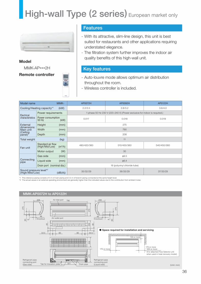
MMK-AP0072H to AP0122H
Features
- With its attractive, slim-line design, this unit is best suited for restaurants and other applications requiring understated elegance.
- The filtration system further improves the indoor air quality benefits of this high-wall unit.
Key features
- Auto-louvre mode allows optimum air distribution throughout the room.
- Wireless controller is included.
Model
MMK-AP∗∗∗2H
Remote controller
Model name MMK- AP0072H AP0092H AP0122H
Cooling/Heating capacity*1 (kW) 2.2/2.5 2.8/3.2 3.6/4.0
Electricalcharacteristics
Power requirements 1-phase 50 Hz 230 V (220–240 V) (Power exclusive for indoor is required.)
Power consumption 50 Hz (kW) 0.017 0.018 0.019
Externaldimensions:Main unit(Ceiling panel)*
Height (mm) 275
Width (mm) 790
Depth (mm) 208
Total weight (kg) 11
Fan unitStandard air flow (High/Mid/Low) (m3/h) 480/420/360 510/450/360 540/450/360
Motor output (W) 30
Connecting pipe
Gas side (mm) φ9.5
Liquid side (mm) φ6.4
Drain port (nominal dia.) 16 (polyvinyl chloride tube)
Sound pressure level*2 (High/Mid/Low) (dB(A)) 35/32/29 36/33/29 37/33/29
*1 This reference piping consists of 5 m of main piping and 2.5 m of branch piping connected at the same height level.*2 The actual values in an external operating environment are generally higher than the indicated values due to the contribution from ambient noise.
(Unit: mm)
High-wall Type (2 series) European market only
Space required for installation and servicing
208
6
48
208
60
275
275
790Air inlet port
Air outlet port
208
48
275
6 Knockout
321
275
Tab for insulation plate
Refrigerant pipe connecting port (Gas side)
Refrigerant pipe connecting port (Liquid side)Drain pipe
60 54.5
208
6054.5
48 48
Knockout
60
100 or more
170 or more* 300 or more170 or more* (For attached Flow Selector unit when used in heat recovery model)
36

Floor Standing Concealed TypeCool air makes for a pleasant indoor environment
Install it in the under a window and air-condition any room effectively.
Easy maintenance
Simplified design of fan and drainage pipe eases maintenance.
Model name MML- AP0071BH AP0091BH AP0121BH AP0151BH AP0181BH AP0241BH
Cooling/Heating capacity*1 (kW) 2.2/2.5 2.8/3.2 3.6/4.0 4.5/5.0 5.6/6.3 7.1/8.0
Electricalcharacteristics
Power requirements 1-phase 50 Hz 230 V (220–240 V)/1-phase 60 Hz 220 V (Separate power supply for indoor units required.)
Power consumption 50 Hz/60 Hz (kW) 0.056/0.058 0.090/0.096 0.095/0.110
Externaldimensions:Main unit
Height (mm) 600
Width (mm) 745 1045
Depth (mm) 220
Total weight (kg) 21 29
Fan unitStandard air flow (High/Mid/Low) (m3/h) 460/400/300 740/600/490 950/790/640
Motor output (W) 19 70
Connecting pipe
Gas side (mm) φ9.5 φ12.7 φ15.9
Liquid side (mm) φ6.4 φ9.5
Drain port (nominal dia.) 20 (Polyvinyl chloride tube)
Sound pressure level*2 (High/Mid/Low) (dB(A)) 36/34/32 42/37/33
MML-AP0071BH to AP0241BH
*1 This reference piping consists of 5 m of main piping and 2.5 m of branch piping connected at the same height level.*2 The actual values in an external operating environment are generally higher than the indicated values due to the contribution from ambient noise.
Model
MML-AP∗∗∗1BH
(Unit: mm)
Space required for installation and servicing
A 610910
B 580880
C 550850
D 47
E58
AP0071BH to AP0121BHAP0151BH to AP0241BH
Pipe connecting port(Liquid side)
Pipe connecting port(Gas side)
2−12×18 long hole(Hole for floor mounting)
Hole for floor mounting
A
C
B
10085
10
2014
5
5014
525
540
2
315
10
140
436
397
274
224
104
129
80
600
10
B
5585220155110
170
12365
135135
D ×100
(Air discharge port size in flange)
(Air discharge port size in flange)
E − 4.7 hole(front side and rear side)
2− 4.7 hole (left/right side each)
Expansion valve box
Ceiling board section
4− 15 hole(for mounting rear side)Electric parts box (earth terminal
is provided in inner side)
150 or more 150 or more
Drain pipe connecting port
Air filter
Model MML-
37

MML-AP0071H to AP0241H
Slim & compact design
- Under-window mounting does not block lighting.- Indoor unit size of 2.2 kW to 7.1 kW is the same.
Air exits from front or top
Distribution can be reversed to suit occupant preference.
Models
MML-AP∗∗∗1H
Model name MML- AP0071H AP0091H AP0121H AP0151H AP0181H AP0241H
Cooling/Heating capacity*1 (kW) 2.2/2.5 2.8/3.2 3.6/4.0 4.5/5.0 5.6/6.3 7.1/8.0
Electricalcharacteristics
Power requirements 1-phase 50 Hz 230 V (220–240 V) (Power exclusively for indoor is required.)/1-phase 60 Hz 220 V
Power consumption 50 Hz/60 Hz (kW) 0.056/0.053 0.092/0.092 0.102/0.113
Externaldimensions:Main unit
Height (mm) 630
Width (mm) 950
Depth (mm) 230
Total weight (kg) 37 40
Fan unitStandard air flow (High/Mid/Low) (m3/h) 480/420/360 900/780/650 1080/930/780
Motor output (W) 45 70
Connecting pipe
Gas side (mm) φ9.5 φ12.7 φ15.9
Liquid side (mm) φ6.4 φ9.5
Drain port (nominal dia.) 20 (Polyvinyl chloride tube)
Sound pressure level*2 (High/Mid/Low) (dB(A)) 39/37/35 45/41/38 49/44/39
*1 This reference piping consists of 5 m of main piping and 2.5 m of branch piping connected at the same height level.*2 The actual values in an external operating environment are generally higher than the indicated values due to the contribution from ambient noise.
(Unit: mm)
Floor Standing Cabinet Type
Space required for installation and servicing
400 120
150
130
Hole for floor mounting (2- 10)
Lower refrigerant piping port(knockout hole 50x100)
95
177
28
Drain pipe connecting port ( 20)
Refrigerant pipe connecting port(Liquid side)
Refrigerant pipe connecting port(Gas side)
1385
(Gas)
(Drain)
(Liquid)
(Gas
)(L
iqui
d)
130
3516
2
106
950
630
Air outlet
Air inlet
Power supply cord hole ( 26 knockout hole)
230
130
(100 left side)
30
50 7035
Refrigerant pipe port (both sides) (knockout hole 50x100)Earth screw (M6)
120
97
Refrigerant pipe port(Knockout hole 130)
Hole for wall mounting (knockout hole)
Long hole for wall mounting
5743
013
3
Piping positional drawing
1000
or m
ore
Wall
Wall
(Front side)
(Front side)
500 or more 30
0 or
m
ore
Air blown from front panel (factory default)
Air blown from topAir blown from top
38

autoswingauto
swing
Floor Standing TypeThin profile suits interior design
Slender, space-saving type (1.7–8.0HP)
Wide outlet
- Corner location is also possible, with right and left auto swing.
- Set the vertical angle manually.
MMF-AP0151H to AP0561H
Model
MMF-AP∗∗∗1H
Model name MMF- AP0151H AP0181H AP0241H AP0271H AP0361H AP0481H AP0561H
Cooling/Heating capacity*1 (kW) 4.5/5.0 5.6/6.3 7.1/8.0 8.0/9.0 11.2/12.5 14.0/16.0 16.0/18.0
Electricalcharacteristics
Power requirements 1-phase 50 Hz 230 V (220–240 V) (Power exclusive for indoor is required.)/1-phase 60 Hz 220 V
Power consumption 50 Hz/60 Hz (kW) 0.150/0.146 0.190/0.195 0.280/0.295 0.350/0.380
Externaldimensions:Main unit
Height (mm) 1750
Width (mm) 600
Depth (mm) 210 390
Total weight (kg) 48 49 65
Fan unitStandard air flow (High/Mid/Low) (m3/h)
900/780/660
1200/1020/840
1920/1680/1380
2160/1860/1560
Motor output (W) 37 63 110 160
Connecting pipe
Gas side (mm) φ12.7 φ15.9
Liquid side (mm) φ6.4 φ9.5
Drain port (nominal dia.) 20 (polyvinyl chloride tube: external dia. 26; internal dia. 20)
Sound pressure level*2 (High/Mid/Low) (dB(A)) 46/43/38 49/45/40 51/48/44 54/50/46
*1 This reference piping consists of 5 m of main piping and 2.5 m of branch piping connected at the same height level.*2 The actual values in an external operating environment are generally higher than the indicated values due to the contribution from ambient noise.
(Unit: mm)
Space required for installation and servicing
Earth screw (M4)
E
DC
50
BA
F
Wall
Pipe holes on side (both sides)(knockout hole)
Drain hose outlet port (both sides)(knockout hole)
Drain hose base
Rear side pipe hole( 130 knockout hole)
Bracket for floor mounting (both sides)
Bracket for wall mounting
Air outlet
600
180 120
Floor fixing bracket screw positions 640
Air inlet
120
165
80pitch30×3
pitch30×3
815
210
631
5925
1040
2017
50
1000
or
mor
e
Wall
Wall(Front side)
(Front side)
500 or more
200
or
mor
e
358
164
204Refrigerant piping joint (Liquid side)
155
Refrigerant piping joint (Gas side)Gas side
Liquid side
AP0151H to AP0271H
AP0361H to AP0561H
D
157
160
C
132
120
Model MMD-
MMF-AP0151H
380
165
215
215
MMF-AP0361H
B
107
125
A
200
380
E
210
390
F
50
40
Refrigerant piping position
Liquid side
Gas side
39
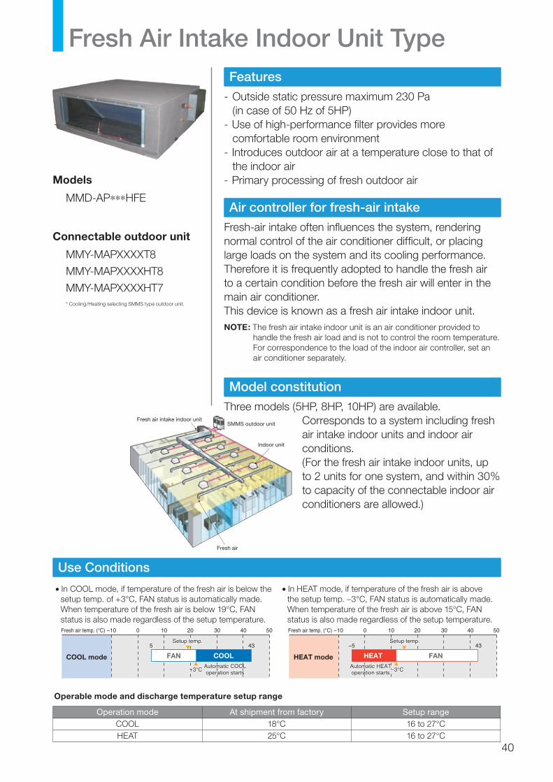
Fresh Air Intake Indoor Unit TypeFeatures
- Outside static pressure maximum 230 Pa (in case of 50 Hz of 5HP)
- Use of high-performance filter provides more comfortable room environment
- Introduces outdoor air at a temperature close to that of the indoor air
- Primary processing of fresh outdoor air
Air controller for fresh-air intake
Fresh-air intake often influences the system, rendering normal control of the air conditioner difficult, or placing large loads on the system and its cooling performance.Therefore it is frequently adopted to handle the fresh air to a certain condition before the fresh air will enter in the main air conditioner.This device is known as a fresh air intake indoor unit.NOTE: The fresh air intake indoor unit is an air conditioner provided to
handle the fresh air load and is not to control the room temperature. For correspondence to the load of the indoor air controller, set an air conditioner separately.
Model constitution
Three models (5HP, 8HP, 10HP) are available.Corresponds to a system including fresh air intake indoor units and indoor air conditions.(For the fresh air intake indoor units, up to 2 units for one system, and within 30% to capacity of the connectable indoor air conditioners are allowed.)
Indoor unit
Fresh air intake indoor unit
Fresh air
SMMS outdoor unit
Models
MMD-AP∗∗∗HFE
Connectable outdoor unit
MMY-MAPXXXXT8
MMY-MAPXXXXHT8
MMY-MAPXXXXHT7* Cooling/Heating selecting SMMS type outdoor unit.
• In COOL mode, if temperature of the fresh air is below the setup temp. of +3°C, FAN status is automatically made. When temperature of the fresh air is below 19°C, FAN status is also made regardless of the setup temperature.
• In HEAT mode, if temperature of the fresh air is above the setup temp. –3°C, FAN status is automatically made. When temperature of the fresh air is above 15°C, FAN status is also made regardless of the setup temperature.
Operable mode and discharge temperature setup range
Operation mode At shipment from factory Setup rangeCOOL 18°C 16 to 27°CHEAT 25°C 16 to 27°C
Use Conditions
FAN COOL
−10Fresh air temp. (°C)
+3°C
COOL mode
0
5 43Setup temp.
Automatic COOLoperation starts
10 20 30 40 50
FANHEAT
−10Fresh air temp. (°C)
−3°C
HEAT mode
0
−5 43Setup temp.
Automatic HEAToperation starts
10 20 30 40 50
+3°C
Setup temp.
Automatic COOLoperation starts −3°C
Setup temp.
Automatic HEAToperation starts
40
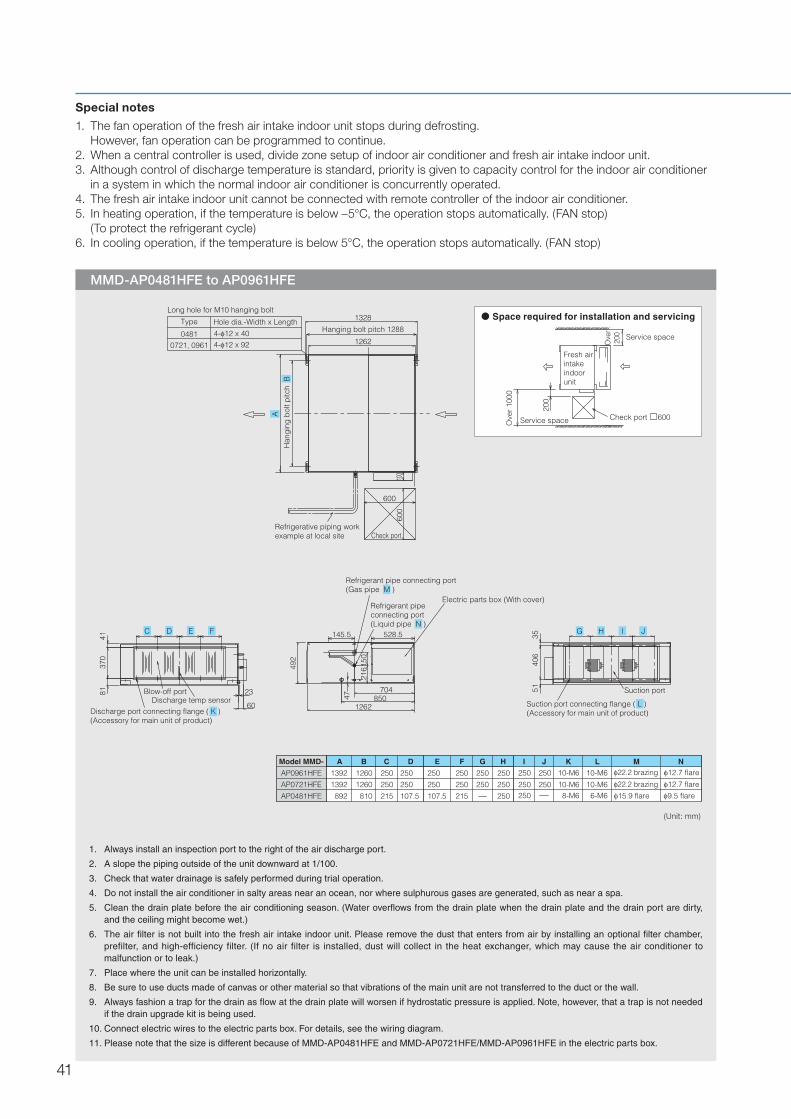
MMD-AP0481HFE to AP0961HFE
1. Always install an inspection port to the right of the air discharge port.
2. A slope the piping outside of the unit downward at 1/100.
3. Check that water drainage is safely performed during trial operation.
4. Do not install the air conditioner in salty areas near an ocean, nor where sulphurous gases are generated, such as near a spa.
5. Clean the drain plate before the air conditioning season. (Water overflows from the drain plate when the drain plate and the drain port are dirty, and the ceiling might become wet.)
6. The air filter is not built into the fresh air intake indoor unit. Please remove the dust that enters from air by installing an optional filter chamber, prefilter, and high-efficiency filter. (If no air filter is installed, dust will collect in the heat exchanger, which may cause the air conditioner to malfunction or to leak.)
7. Place where the unit can be installed horizontally.
8. Be sure to use ducts made of canvas or other material so that vibrations of the main unit are not transferred to the duct or the wall.
9. Always fashion a trap for the drain as flow at the drain plate will worsen if hydrostatic pressure is applied. Note, however, that a trap is not needed if the drain upgrade kit is being used.
10. Connect electric wires to the electric parts box. For details, see the wiring diagram.
11. Please note that the size is different because of MMD-AP0481HFE and MMD-AP0721HFE/MMD-AP0961HFE in the electric parts box.
Special notes
1. The fan operation of the fresh air intake indoor unit stops during defrosting. However, fan operation can be programmed to continue.2. When a central controller is used, divide zone setup of indoor air conditioner and fresh air intake indoor unit.3. Although control of discharge temperature is standard, priority is given to capacity control for the indoor air conditioner
in a system in which the normal indoor air conditioner is concurrently operated.4. The fresh air intake indoor unit cannot be connected with remote controller of the indoor air conditioner.5. In heating operation, if the temperature is below –5°C, the operation stops automatically. (FAN stop) (To protect the refrigerant cycle)6. In cooling operation, if the temperature is below 5°C, the operation stops automatically. (FAN stop)
(Unit: mm)
Space required for installation and servicing
Check port 600
Ove
r 10
00
200
Ove
r20
0 Service space
Service space
Fresh air intake indoor unit
0481 4- 12 x 40
0721, 0961 4- 12 x 92
Type
Long hole for M10 hanging bolt
Hanging bolt pitch 1288
1328Hole dia.-Width x Length
100
Han
gin
g b
olt p
itch
B
A
1262
Check port
600
600
Refrigerative piping workexample at local site
Discharge port connecting flange ( K )(Accessory for main unit of product)
370
8141
C
Blow-off port
60
23
ED F
Refrigerant pipe connecting port(Gas pipe M )
Refrigerant pipe connecting port(Liquid pipe N )
492
47
216
850704
528.5
5140
6
150
35
Electric parts box (With cover)
Suction port
G IH J
1262Discharge temp sensor Suction port connecting flange ( L )
(Accessory for main unit of product)
Model MMD- A CB D E F HG I J K L M N
AP0481HFE 892 107.5215810 215107.5 250
12601392AP0721HFE 250250250 250 250250
1260AP0961HFE 1392 250 250250 250 250250
8-M6 9.5 flare15.9 flare6-M6250
250
10-M6 12.7 flare10-M6 22.2 brazing250 250
250 12.7 flare22.2 brazing10-M610-M6
145.5
41
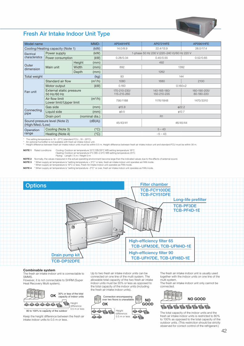
Model name MMD- AP0481HFE AP0721HFE AP0961HFE
Cooling/Heating capacity (Note 1) (kW) 14.0/8.9 22.4/13.9 28.0/17.4
Electricalcharacteristics
Power supply (kW) 1-phase 50 Hz 230 V (220–240 V)/60 Hz 220 V
Power consumption (kW) 0.28/0.34 0.45/0.55 0.52/0.65
Outer dimension Main unit
Height (mm) 492
Width (mm) 892 1392
Depth (mm) 1262
Total weight (kg) 93 144
Fan unit
Standard air flow (m3/h) 1080 1680 2100
Motor output (kW) 0.160 0.160×2
External static pressure50 Hz/60 Hz
170-210-230/115-215-260
140-165-180/150-210-235
160-190-205/80-180-220
Air flow limit (m3/h)Lower limit/Upper limit
756/1188 1176/1848 1470/3310
Connecting pipe
Gas side (mm) φ15.9 φ22.2
Liquid side (mm) φ9.5 φ12.7
Drain port (nominal dia.) R1
Sound pressure level (Note 2) (dB(A))(High/Med./Low)
45/43/41 46/45/44
Operation range
Cooling (Note 3) (°C) 5 – 43
Heating (Note 4) (°C) –5 – 43
Fresh Air Intake Indoor Unit Type
* The setting temperature is 16 – 27°C (standard FCU…18 – 29°C).* An optional humidifier is not available with fresh air intake indoor unit.* Height difference between fresh air intake indoor units must be within 0.5 m. Height difference between fresh air intake indoor unit and standard FCU must be within 30 m.
NOTE 1 Rated conditions Cooling: Outdoor air temperature 33°C DB/28°C WB setting temperature 18°C Heating: Outdoor air temperature 0°C DB/–2.9°C WB setting temperature 25°C Piping: Length 7.5 m / Height 0 m
NOTE 2 Normally, the values measured in the actual operating environment become large than the indicated values due to the effects of external sound.NOTE 3 * When supply air temperature is “setting temperature + 3°C” or less, fresh air intake indoor unit operates as FAN mode.
* When supply air temperature is 19°C or less, Fresh Air Intake Indoor unit operates as FAN mode.NOTE 4 * When supply air temperature is “setting temperature –3°C” or over, fresh air intake indoor unit operates as FAN mode.
Combinable systemThe fresh air intake indoor unit is connectable to SMMS.However, it is not connectable to SHRM (Super Heat Recovery Multi system).
Height difference:0.5 m or less
80 to 100% to capacity of the outdoor
30% or less of the total capacity of indoor unitsOK
Keep the height difference between the fresh air intake indoor units to 0.5 m or less.
The fresh air intake indoor unit is usually used together with the indoor units on one line of the multi system.The fresh air intake indoor unit only cannot be connected.
NO GOOD
The total capacity of the indoor units and the fresh air intake indoor units is restricted to 80% to 100% as opposed to the total capacity of the outdoor units. (This restriction should be strictly observed for correct control of the refrigerant.)
Up to two fresh air intake indoor units can be connected on one line of the multi system. The allowable total capacity of the two fresh air intake indoor units must be 30% or less as opposed to the total capacity of the indoor units (including the fresh air intake indoor units).
Options Filter chamberTCB-FCY100DETCB-FCY51DFE
Long-life prefilter
TCB-PF3DETCB-PF4D-1E
High-efficiency filter 65TCB-UFM3DE, TCB-UFM4D-1E
High-efficiency filter 90TCB-UFH7DE, TCB-UFH8D-1E
Drain pump kit
TCB-DP32DFE
Connection encompassing over two floors is unavailable
OKNO
GOOD
Height difference:0.5 m or less
42

Indoor unit Parts Name Model NameApplied Model
Notes RemarksSMMS
4-way air dischargecassette type
Ceiling panelRBC-U31PG(W)-ERBC-U31PGS(W)-E*RBC-U31PGS(WS)-E*
MMU-AP∗∗∗2H
Required accessory
Fresh air inlet box TCB-GB1602UE For fresh air intake by using the knockout hole of Fresh air and filter chamber. (dia.=100 mm)
Use with TCB-GFC1602UE
Fresh air and filter chamber TCB-GFC1602UE For fresh air inlet box
Auxiliary fresh air flange TCB-FF101URE2 For easy fresh air intake by using the knockout hole of indoor unit. (dia.=100 mm)
Spacer for height adjustment TCB-SP1602UE Height=50 mmAir discharge direction kit TCB-BC1602UE Air direction charge by cutting off air discharge port (3 pcs.)
Compact 4-waycassette (600 × 600) type
Ceiling panel RBC-UM11PG(W)-E MMU-AP∗∗∗1MH Required accessor
Auxiliary fresh air flange TCB-FF101URE2 For easy fresh air intake by using the knockout hole of indoor unit. (dia.=100 mm)
2-way air dischargecassette type Ceiling panel
RBC-UW136PG MMU-AP0071WH/0091/0121WHRequired accessoryRBC-UW266PG MMU-AP0151 to 0301WH
RBC-UW466PG MMU-AP481WH China market only
1-way air discharge cassette type
Ceiling panelRBC-UY136PG MMU-AP∗∗∗1YH Required accessoryRBC-US21PGE
MMU-AP∗∗∗2SH
Required accessoryFront air discharge unit TCB-BUS21HWE
Auxiliary fresh air flange TCB-FF101URE2 For easy fresh air intake by using the knockout hole of indoor unit. (dia.=100 mm)
Concealed duct type
High-efficiency filter 65 (for rear suction)
TCB-UFM11BFCE MMD-AP0071/0091/0121BH
Dust collecting effect: 65% (NBS Colorimentric method)
Use with TCB-FC281BETCB-UFM21BFCE MMD-AP0151/0181BH Use with TCB-FC501BETCB-UFM11BFCE (2 pcs.) MMD-AP0241/0271/0301BH Use with TCB-FC801BETCB-UFM21BFCE (2 pcs.) MMD-AP0361/0481/0561BH Use with TCB-FC1401BE
High-efficiency filter 90(for rear suction)
TCB-UFH51BFCE MMD-AP0071/0091/0121BH
Dust collecting effect: 90%(NBS Colorimentric method)
Use with TCB-FC281BETCB-UFH61BFCE MMD-AP0151/0181BH Use with TCB-FC501BETCB-UFH51BFCE (2 pcs.) MMD-AP0241/0271/0301BH Use with TCB-FC801BETCB-UFH61BFCE (2 pcs.) MMD-AP0361/0481/0561BH Use with TCB-FC1401BE
Filter chamber(for rear suction)
TCB-FC281BE MMD-AP0071/0091/0121BH
For high-efficiency filterTCB-FC501BE MMD-AP0151/0181BHTCB-FC801BE MMD-AP0241/0271/0301BHTCB-FC1401BE MMD-AP0361/0481/0561BH
High-efficiency filter 65(for underside suction)
TCB-UFM11BE MMD-AP0071/0091/0121BH
Dust collecting effect: 65%(NBS Colorimentric method)
TCB-UFM21BE MMD-AP0151/0181BHTCB-UFM31BE MMD-AP0241/0271/0301BHTCB-UFM41BE MMD-AP0361/0481/0561BH
High-efficiency filter 90(for underside suction)
TCB-UFH51BE MMD-AP0071/0091/0121BH
Dust collecting effect: 90%(NBS Colorimentric method)
TCB-UFH61BE MMD-AP0151/0181BHTCB-UFH71BE MMD-AP0241/0271/0301BHTCB-UFH81BE MMD-AP0361/0481/0561BH
Ceiling panel(half panel for underside suction)
RBC-UD281PE(W) MMD-AP0071/0091/0121BHRBC-UD501PE(W) MMD-AP0151/0181BHRBC-UD801PE(W) MMD-AP0241/0271/0301BHRBC-UD1401PE(W) MMD-AP0361/0481/0561BH
Suction canvas(for underside suction)
TCB-CA281BE MMD-AP0071/0091/0121BH
Adjustment height of the suction canvas is between 40 mm and 100 mm
TCB-CA501BE MMD-AP0151/0181BHTCB-CA801BE MMD-AP0241/0271/0301BHTCB-CA1401BE MMD-AP0361/0481/0561BH
Filter kit for underside
TCB-FK281BE MMD-AP0071/0091/0121BH
Kit of underside prefilter & shielding plate of rear suction
TCB-FK501BE MMD-AP0151/0181BHTCB-FK801BE MMD-AP0241/0271/0301BHTCB-FK1401BE MMD-AP0361/0481/0561BH
Concealed duct high static pressure type
High-efficiency filter 65
TCB-UFM1D-1E MMD-AP0181H
Dust collecting effect: 65%(NBS Colorimentric method)
Use with TCB-FCY21DETCB-UFM2D-1E (2 pcs.) MMD-AP0241/0271/0361H Use with TCB-FCY31DETCB-UFM1D-1E (2 pcs.) MMD-AP0481H Use with TCB-FCY51DETCB-UFM3DE MMD-AP0721/0961H Use with TCB-FCY100DE
High-efficiency filter 90
TCB-UFH5D-1E MMD-AP0181H
Dust collecting effect: 90%(NBS Colorimentric method)
Use with TCB-FCY21DETCB-UFH6D-1E (2 pcs.) MMD-AP0241/0271/0361H Use with TCB-FCY31DETCB-UFH5D-1E (2 pcs.) MMD-AP0481H Use with TCB-FCY51DETCB-UFH7DE MMD-AP0721/0961H Use with TCB-FCY100DE
Long life prefilter
TCB-PF1D-1E MMD-AP0181H
Dust collecting effect: 50%(Weight method)
Use with TCB-FCY21DETCB-PF2D-1E (2 pcs.) MMD-AP0241/0271/0361H Use with TCB-FCY31DETCB-PF1D-1E (2 pcs.) MMD-AP0481H Use with TCB-FCY51DETCB-PF3DE MMD-AP0721/0961H Use with TCB-FCY100DE
Filter chamber
TCB-FCY21DE MMD-AP0181H
For high-efficiency filter or long life prefilterTCB-FCY31DE MMD-AP0241/0271/0361HTCB-FCY51DE MMD-AP0481HTCB-FCY100DE MMD-AP0721/0961H
Drain pump kitTCB-DP31DE MMD-AP0181H to 0481H Stand-up 330 or less
(from bottom face of ceiling)TCB-DP32DE MMD-AP0721/0961H
Slim duct type Auxiliary fresh air flange TCB-FF101URE2 MMD-AP∗∗∗1SPH For fresh air intake by using the knockout hole of indoor unit. (dia.=100 mm)
Ceiling typeDrain pump kit TCB-DP22CE2
MMC-AP0151/0181H Stand-up 600 or less(from bottom face of ceiling)
Use with TCB-KP12CE2MMC-AP0241 to 0581H Use with TCB-KP22CE2
Elbow piping kitTCB-KP12CE2 MMC-AP0151/0181H
Needed when Drain Pump Kit is usedTCB-KP22CE2 MMC-AP0241 to 0581H
Fresh air intakeindoor unit type
High-efficiency filter 65TCB-UFM3DE MMD-AP0721/0961HFE Dust collecting effect: 65%
(NBS Colorimentric method)Use with TCB-PF3DE
TCB-UFM4D-1E MMD-AP0481HFE Use with TCB-PF4D-1E
High-efficiency filter 90TCB-UFH7DE MMD-AP0721/0961HFE Dust collecting effect: 90%
(NBS Colorimentric method)Use with TCB-PF3DE
TCB-UFH8D-1E MMD-AP0481HFE Use with TCB-PF4D-1E
Long life prefilterTCB-PF3DE MMD-AP0721/0961HFE Dust collecting effect: 50%
(Weight method)Use with TCB-FCY100DE
TCB-PF4D-1E MMD-AP0481HFE Use with TCB-FCY51DFE
Filter chamberTCB-FCY51DFE MMD-AP0481HFE
For high-efficiency filter or long life prefilterTCB-FCY100DE MMD-AP0721/0961HFE
Drain pump kit TCB-DP32DFE MMD-AP0481/0721/0961HFE Stand-up 330 or less (from bottom face of ceiling)
1. Indoor accessories
Indoor Unit Accessories
* European market only
43

2. Combination Pattern
1) Accessory for 4-way air discharge cassette type: combination pattern
1 2 3 4 5 6
Ceiling panel
Fresh air inlet box + Fresh air and filter chamber
Fresh air and filter chamber
Auxiliary fresh air flange
Spacer for height
adjustment
Air discharge
direction kit
1 Ceiling panel OK OK OK OK OK
2 Fresh air inlet box + Fresh air and filter chamber OK OK — OK
3 Fresh air and filter chamber OK OK OK OK
4 Auxiliary fresh air flange OK OK OK OK OK
5 Spacer for height adjustment OK — OK OK OK
6 Air discharge direction kit OK OK OK OK OK
2) Accessory for concealed duct type: combination pattern
1 2 3 4 5 6 7 9
For rear suction For underside suction
High-efficiency filter 65(For rear suction)
High-efficiency filter 90(For rear suction)
Filter chamber(for rear suction)
High-efficiency filter 65
(for underside suction)
High-efficiency filter 90
(for underside suction)
Ceiling panel
(half panel for
underside suction)
Suction canvas
(for underside suction)
Filter kit for underside*
1 High-efficiency filter 65 (for rear suction) — OK — — — — —
2 High-efficiency filter 90 (for rear suction) — OK — — — — —
3 Filter chamber (for rear suction) OK OK — — — — —
4 High-efficiency filter 65 (for underside suction) — — — — OK OK OK
6 High-efficiency filter 90 (for underside suction) — — — — OK OK OK
7 Ceiling panel (half panel for underside suction) — — — OK OK OK OK
8 Suction canvas (for underside suction) — — — OK OK OK OK
9 Filter kit for underside* — — — OK OK OK OK
3) Accessory for concealed duct high static pressure type/fresh air intake indoor unit type: combination pattern
1 2 3 4 5
High-efficiency filter 65
High-efficiency filter 90
Long life prefilter
Filter chamber
Drain pump kit
1 High-efficiency filter 65 — OK OK OK
2 High-efficiency filter 90 — OK OK OK
7 Long life prefilter OK OK OK OK
8 Filter chamber OK OK OK OK
9 Drain pump kit OK OK OK OK
* In case of underside,Filter kit is required accessory
Indoor Unit Accessories
44

Allowable length/height difference of refrigerant piping
• Systemrestrictions
• Allowablelengthandheightdifferenceofrefrigerantpiping
Refrigerant Piping Design
Allowable value Piping section
Piping length
Total extension of pipe (Liquid pipe, actual length) 300 mLA + LB + La + Lb + Lc + Ld + L1 + L2 + L3 + L4+L5 + L6 + L7 + a + b + c + d + e + f + g + h + i + j
Farthest piping length L *Actual length 150 m
LA + LB + Ld + L1 + L3 + L4 + L5 + L6 + jEquivalent length 175 m
Equivalent length of farthest piping from 1st branching Li * 65 m L3 + L4 + L5 + L6 + j
Equivalent length of farthest piping between outdoor units LO * 25 m LA + LB + Ld, (LA + Lb, LA + LB + Lc)
Max. equivalent length of main piping *** 85 m L1
Max. equivalent length of outdoor unit connecting piping 10 m Ld, (La, Lb, Lc)
Max. actual length of indoor unit connecting piping 30 m a, b, c, d, e, f, g, h, i, j
Height difference
Height between indoor and outdoor units H1Upper outdoor unit 50 m —
Lower outdoor unit 40 m ** —
Height between indoor units H2 30 m —
Height between outdoor units H3 5 m —
* (D) is outdoor unit farthest from 1st branching, and ( j ) is indoor unit farthest from 1st branching.** If the height difference (H2) between indoor units exceeds 3 m, set below 30 m.*** If the maximum capacity of combination of the outdoor units is 46HP or more, the maximum equivalent length is restricted up to 70 m.
Max. No. of combined outdoor units 4 units
Max. capacity of combined outdoor units 48HP
Max. No. of connected indoor units 48 units
Max. capacity of combined indoor unitsH2 ≤ 15 135%
H2 > 15 105%
NOTE 1 Combination of outdoor units: Header unit (1 unit) + Follower units (0 to 3 units). Header unit is the outdoor unit nearest to the connected indoor units.NOTE 2 Install the outdoor units in order of capacity. (Header unit > Follower unit 1 > Follower unit 2 > Follower unit 3)NOTE 3 Piping to indoor units shall be perpendicular to piping to the head outdoor unit as <Ex.1>. Do not connect piping to indoor units in the same direction of Head outdoor unit as <Ex.2>.
NOTE:In case of connecting method <Ex. 2>, a large amount of refrigerant and refrigerant oil may return to the head unit.Therefore, set the T-shape joint so that oil does not enter directly.
Outdoor unit
T-shape branching joint
La Lb LcLA LB
Mainpiping
L1
1st branching section
Connecting piping of outdoor unit
AHeader
unit
BFollower
unit 1
CFollower
unit 2
Headerunit
Followerunit 1
Followerunit 2
Headerunit
Followerunit 1
Followerunit 2
DFollower
unit 3
Main connecting piping between outdoor units
Branching piping L2
Connecting piping of indoor unit
a b c d e
f g h i j
L4 L5 L6
L3
Branching header
Indoor unit
Indoor unit
Y-joint
<Ex. 2><Ex. 1>
Ld
Height difference between outdoor unitsH3 5 m
Height difference between outdoor unitsH1 50 m
Height difference between indoor unitsH2 30 m
L7
Equivalent length corresponding to farthest piping L 175 m
Equivalent length corresponding to farthest piping after 1st branching Li 65 m
Length corresponded to farthest piping between outdoor units LO 25 m
45

*1 Code is determined according to the capacity rank.*2 When using Y-shape branching joint for 1st branching, select according to capacity code of outdoor unit.*3 For 1 line after header branching, indoor units with a maximum of 6.0 capacity code in total can be connected.*4 If the pipe size is φ19.0 or more, use a hard type or half hard type for material of the pipe.*5 The maximum equivalent length of the main pipe should be 70 m or shorter.
Selection of refrigerant piping
(1) Pipe size of outdoor unit (Table 1)
(2) Connecting pipe size between outdoor units (Table 2)
(5) Piping of indoor unit (Table 5)
(6) Selection of branching section (Table 6)
Model name MMY- Gas side Liquid side
MAP0501T8 MAP0501HT8 MAP0501HT7 φ15.9 φ9.5
MAP0601T8 MAP0601HT8 MAP0601HT7 φ19.1 φ9.5
MAP0801T8 MAP0801HT8 MAP0801HT7 φ22.2 φ12.7
MAP1001T8 MAP1001HT8 MAP1001HT7 φ22.2 φ12.7
MAP1201T8 MAP1201HT8 MAP1201HT7 φ28.6 φ12.7
Total capacity code of outdoor units at downstream side
Gas side Liquid side Balance pipe
14 to below 22 φ28.6 φ15.9
φ9.522 to below 26 φ34.9 φ15.9
26 to below 36 φ34.9 φ19.1
36 or more φ41.3 φ22.2
(3) Size of main pipe (Table 3)
(4) Pipe size between branching sections (Table 4)
Total capacity code of all outdoor units *1 Gas side Liquid side
Below 6 φ15.9 φ9.5
6 to below 8 φ19.1 φ9.5
8 to below 12 φ22.2 φ12.7
12 to below 14 φ28.6 φ12.7
14 to below 22 φ28.6 φ15.9
22 to below 26 φ34.9 φ15.9
26 to below 36 φ34.9 φ19.1
36 to below 46 φ41.3 φ22.2
46 or more φ41.3 *5 φ22.2
Total capacity code of indoor units atdownstream side *1 Gas side Liquid side
2.8 or less φ12.7 φ9.5
2.8 to below 6.4 φ15.9 φ9.5
6.4 to below 12.2 φ22.2 φ12.7
12.2 to below 20.2 φ28.6 φ15.9
20.2 to below 25.2 φ34.9 φ15.9
25.2 to below 35.2 φ34.9 φ19.1
35.2 or more φ41.3 φ22.2
Capacity rank Gas side Liquid side
007 type to 012 type
Actual length 15 m or less φ9.5 φ6.4
Actual length exceeds 15 m φ12.7 φ6.4
015 type to 018 type φ12.7 φ6.4
024 type to 056 type φ15.9 φ9.5
072 type to 096 type φ22.2 φ12.7
(7) Minimum wall thickness for R410A application (Table 7)
Soft Half hard or hard OD (inch) OD (mm) Minimum wall thickness (mm)
OK OK 1/4” 6.35 0.80
OK OK 3/8” 9.52 0.80
OK OK 1/2” 12.70 0.80
OK OK 5/8” 15.88 1.00
NG
*4
OK 3/4” 19.05 1.00
NG OK 7/8” 22.20 1.00
NG OK 1.1/8” 28.58 1.00
NG OK 1.3/8” 34.92 1.10
NG OK 1.5/8” 41.28 1.25
Total capacity code of indoor unit *1 Model name
Y-shapebranching joint
*2
Below 6.4 RBM-BY54E
6.4 to below 14.2 RBM-BY104E
14.2 to below 25.2 RBM-BY204E
25.2 or more RBM-BY304E
Branchingheader *3
For 4 branchingBelow 14.2 RBM-HY1043E
14.2 to below 25.2 RBM-HY2043E
For 8 branchingBelow 14.2 RBM-HY1083E
14.2 to below 25.2 RBM-HY2083E
T-shapebranching joint(For connecting
outdoor unit)
1 set of 3 types of T-shape joint pipes asdescribed below:
The required quantity is arranged and combined at the site.
•Balancepipe(Corresponded difference φ9.52) × 1
•Pipingatliquidside(Corresponded difference φ9.5 to φ22.1) × 1
•Pipingatgasside(Corresponded difference φ15.9 to φ41.3) × 1
RBM-BT13E
Determine thickness of the main pipe according to capacity of the outdoor units.
If the total capacity code value of indoor units exceeds that of outdoor units, apply the capacity code of outdoor units.
(1)
(1)
(1) (1)
(4)
(6)
(4)
(4)
(5) (5) (5) (5) (5)
(5) (5) (5) (5) (5)
(4) (4)
(4)
(2) (2)
Outdoor unit
(2) Balance pipe
Main connecting piping between outdoor units
(3) Main piping
Branching piping (6) Header branching pipe
1st branching section
Indoor unit connecting piping
Y-shape branching joint
Indoor unit connecting piping
Indoor unit
Indoor unit
Headerunit
Followerunit 1
Followerunit 2
Followerunit 3
(6) T-shape branching jointOutdoor unit
connecting piping
Refrigerant Piping Design
46

Charging requirement with additional refrigerantAfter the system has been vacuumed, replace the vacuum pump with a refrigerant cylinder and charge the system with additional refrigerant.
Calculating the amount of additional refrigerant required
Refrigerant in the system when shipped from the factory
When the system is charged with refrigerant at the factory, the amount of refrigerant needed for the pipes at the site is not included. Calculate the additional amount needed, and add that amount to the system.
(Calculation)Additional refrigerant charge amount is calculated from size of liquid pipe at site and its actual length.
Example: Additional charge amount R (kg) = (L1 x 0.025 kg/m) + (L2 x 0.055 kg/m) + (L3 x 0.105 kg/m) + (3.0 kg) L1: Actual total length of liquid pipe φ6.4 (m) L2: Actual total length of liquid pipe φ9.5 (m) L3: Actual total length of liquid pipe φ12.7 (m)
5HP 6HP 8HP 10HP 12HP
Refrigerant amount charged in factoryHeat pump model 8.5 kg 8.5 kg 11.8 kg 11.8 kg 11.8 kg
Cooling only model 8.0 kg 8.0 kg 11.0 kg 11.0 kg 11.0 kg
Pipe dia. at liquid side φ6.4 φ9.5 φ12.7 φ15.9 φ19.0 φ22.2
Additional refrigerant amount / 1 m 0.025 kg 0.055 kg 0.105 kg 0.160 kg 0.250 kg 0.350 kg
Additional refrigerant charge amount at site =
Actual length of liquid pipe ×Additional refrigerant charge amount per liquid pipe 1 m (Table 7-1)
+ Compensation by system HP (Table 7-2)
Table 7-2
Table 7-1
Combined horse power (HP)
Outdoor combination(HP)
Compensation by system HP (kg)
28 10 10 8 –2.0
30 10 10 10 0.0
3212 10 10 1.0
8 8 8 8 –6.0
3412 12 10 3.0
10 8 8 8 –6.0
3612 12 12 4.0
10 10 8 8 –6.0
38 10 10 10 8 –6.0
40 10 10 10 10 –5.0
42 12 10 10 10 –4.0
44 12 12 10 10 –2.0
46 12 12 12 10 0.0
48 12 12 12 12 2.0
Combined horse power (HP)
Outdoor combination(HP)
Compensation by system HP (kg)
5 5 0.0
6 6 0.0
8 8 1.5
10 10 2.5
12 12 3.5
14 8 6 0.0
16 8 8 0.0
18 10 8 0.0
20 10 10 3.0
2212 10 5.0
8 8 6 0.0
2412 12 7.0
8 8 8 –4.0
26 10 8 8 –4.0
Refrigerant Piping Design
47

General(1) Perform wiring of the power supply in conformance with the regulations of the local electric company.(2) For the control wires connecting indoor units, outdoor units, and between indoor and outdoor units, use of double-core
shield wires is recommended to prevent noise trouble.(3) Be sure to set the earth leakage breaker and the switches to the power supply section of the indoor unit.(4) Supply power to each outdoor unit and provide an earth leakage breaker or hand switch for each outdoor unit.(5) Never connect 220–240 V power to the terminal block (U1, U2, U3, U4, U5, U6) for control cables.
(Problems may occur.)(6) Store wiring system for control and refrigerant piping system in the same line.(7) Arrange the cables so that the electric wires do not come in contact with high-temperature part of the pipe;
otherwise coating melts and an accident may occur.(8) Do not turn on power of the indoor unit until vacuuming of the refrigerant pipe is completed.
For outdoor unit power supply• Selectthepowersupplycablingandfuseofeachoutdoorunitfromthefollowingspecifications:
Cable 5-core, in conformance with Design 60245 IEC 66
• Donotconnecttheoutdoorunitsby crossing outside of them (see illustration), but connect them via the incorporated terminal block (L1, L2, L3, N).
• Unitcapacitiesandpowersupplywiresizes(Reference)
• Determinethewiresizeforindoorunitaccordingtothenumberofconnectedindoorunitsdownstream.• Observelocalregulationsregardingwiresizeselectionandinstallation.
Electrical wiring design
L1 L2 L3 N L1 L2 L3 N L1 L2 L3 N L1 L2 L3 NOutdoor power supply3-phase 380–415 V, 50 Hz
380 V, 60 Hz
Pull box
Earth
Outdoorpower source
Indoorpower source
3-phase50 Hz 380–415 Vor 60 Hz 380 VEarth leakage breakerhand switch
Single phase 50 Hz 220–240 Vor 60 Hz 220 VEarth leakage breakerpower switch
Model Outdoor power supply
MMY-AP××××T8, HT8 3-phase, 380–415 V, 50 Hz
MMY-AP××××HT7 3-phase, 380 V, 60 Hz
ModelMMY-
Power supply wiring
Wire size Field fuse
MAP0501T8 MAP0501HT8 MAP0501HT7 3.5 mm² (AWG #12) Max. 26 m 20 A
MAP0601T8 MAP0601HT8 MAP0601HT7 3.5 mm² (AWG #12) Max. 26 m 20 A
MAP0801T8 MAP0801HT8 MAP0801HT7 3.5 mm² (AWG #10) Max. 20 m 30 A
MAP1001T8 MAP1001HT8 MAP1001HT7 5.5 mm² (AWG #10) Max. 28 m 30 A
MAP1201T8 MAP1201HT8 MAP1201HT7 5.5 mm² (AWG #10) Max. 27 m 30 A
Wiring Design
48
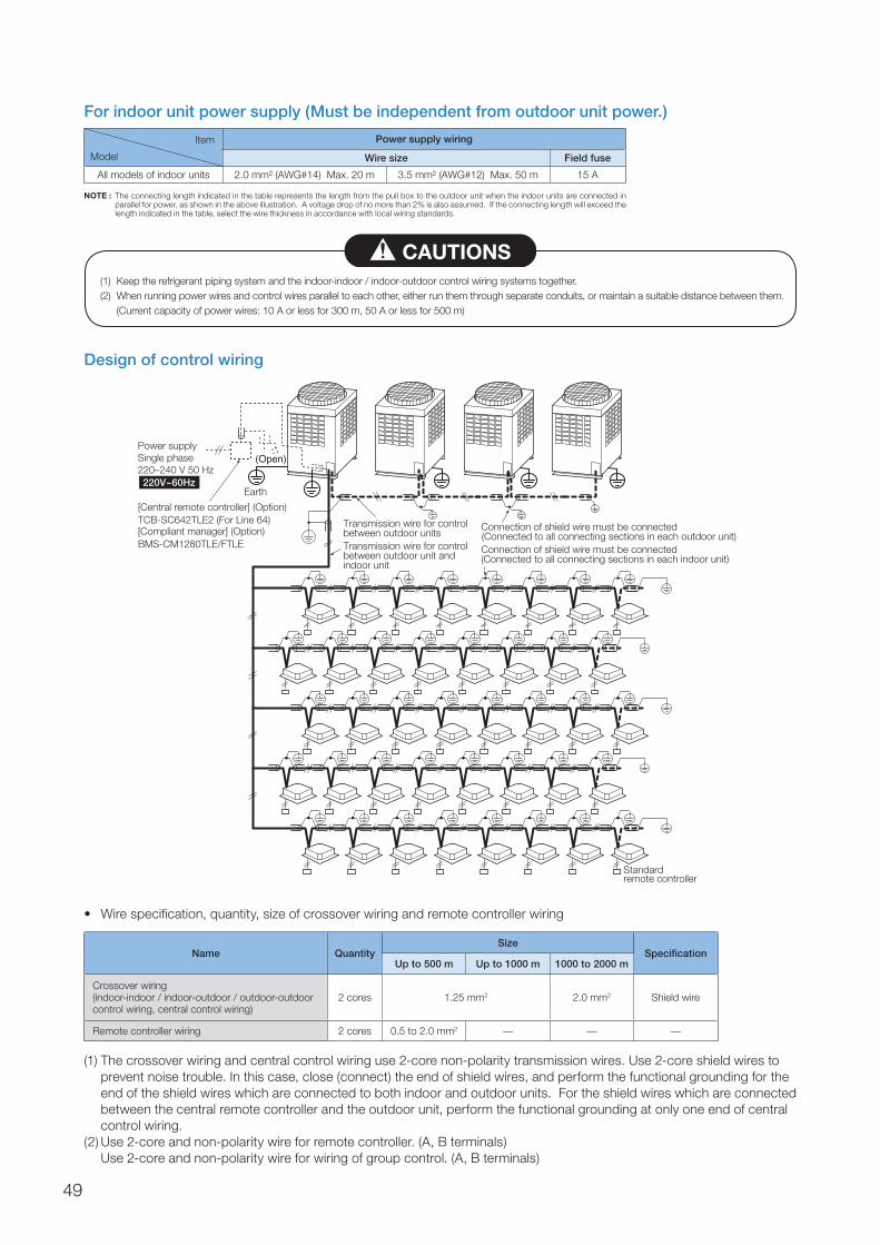
For indoor unit power supply (Must be independent from outdoor unit power.)
Design of control wiring
(1) The crossover wiring and central control wiring use 2-core non-polarity transmission wires. Use 2-core shield wires to prevent noise trouble. In this case, close (connect) the end of shield wires, and perform the functional grounding for the end of the shield wires which are connected to both indoor and outdoor units. For the shield wires which are connected between the central remote controller and the outdoor unit, perform the functional grounding at only one end of central control wiring.
(2) Use 2-core and non-polarity wire for remote controller. (A, B terminals) Use 2-core and non-polarity wire for wiring of group control. (A, B terminals)
Power supply wiring
Wire size Field fuse
All models of indoor units 2.0 mm² (AWG#14) Max. 20 m 3.5 mm² (AWG#12) Max. 50 m 15 A
NOTE : The connecting length indicated in the table represents the length from the pull box to the outdoor unit when the indoor units are connected in parallel for power, as shown in the above illustration. A voltage drop of no more than 2% is also assumed. If the connecting length will exceed the length indicated in the table, select the wire thickness in accordance with local wiring standards.
(1) Keep the refrigerant piping system and the indoor-indoor / indoor-outdoor control wiring systems together.(2) When running power wires and control wires parallel to each other, either run them through separate conduits, or maintain a suitable distance between them.
(Current capacity of power wires: 10 A or less for 300 m, 50 A or less for 500 m)
CAUTIONS
Earth
(Open)
Standard remote controller
[Central remote controller] (Option)TCB-SC642TLE2 (For Line 64)[Compliant manager] (Option)BMS-CM1280TLE/FTLE
Transmission wire for control between outdoor unitsTransmission wire for control between outdoor unit and indoor unit
Connection of shield wire must be connected (Connected to all connecting sections in each outdoor unit)Connection of shield wire must be connected (Connected to all connecting sections in each indoor unit)
Power supply Single phase 220–240 V 50 Hz 220V~60Hz
• Wirespecification,quantity,sizeofcrossoverwiringandremotecontrollerwiring
Name QuantitySize
SpecificationUp to 500 m Up to 1000 m 1000 to 2000 m
Crossover wiring(indoor-indoor / indoor-outdoor / outdoor-outdoor control wiring, central control wiring)
2 cores 1.25 mm2 2.0 mm2 Shield wire
Remote controller wiring 2 cores 0.5 to 2.0 mm2 — — —
Item
Model
49

Control wiring diagram(1) All control wiring is 2-core and non-polarity wire.(2) Be sure to use shield wire for the following wiring to prevent noise trouble.
• Outdoor-outdoor/indoor-indoor/outdoor-indoorcontrolwiring,centralcontrolwiring.
Table-1 Control wiring between indoor and outdoor units (L1, L2, L3), central control wiring (L4)
Table-2 Control wiring between outdoor units (L5)
Table-3 Remote controller wiring (L6, L7)
U3 U4
U1 U2
U1U3
U2U4
U5 U6
U1 U2
A B
Remotecontroller
Outdoor unit
Indoor unit
U3 U4
U1 U2 U5 U6
U1 U2
A B
U1 U2
A B
U1 U2
A B
U1 U2
A B
U3 U4
U1 U2 U5 U6
U3 U4
U1 U2 U5 U6
U3 U4
U1 U2 U5 U6
Central controldevice
SMMS
Headerunit
Followerunit
Followerunit
Followerunit
U3 U4
U1 U2 U5 U6
U1 U2
A B
Remote controllerRemote controller
U1 U2
A B
U1 U2
A B
U3 U4
U1 U2 U5 U6
L1 L5
L6L7
L4
3L2L
Headerunit
Headerunit
Followerunit
Table-1
Table-2
Table-3
Table-1
Wiring 2-core, non-polarity
Type Shield wire
Size Length1.25 mm2 : Up to 1000 m2.0 mm2 : Up to 2000 m*1
Wiring 2-core, non-polarity
Type Shield wire
Size Length1.25 mm² to 2.0 mm²Up to 100 m (L5)
Wiring 2-core
Size 0.5 mm² to 2.0 mm²
Length•Upto500m(L6+L7)•Upto400mincaseofwirelessremotecontrolleringroupcontrol.•Upto200mtotallengthofcontrolwiringbetweenindoorunits(L6)
*1 Total of control wiring length for all refrigerant circuits ( L1 + L2 + L3 + L4 )
Wiring Design
50

3025201510–10
–5
0
5
10
15
20
25
30
35
40
45
In cooling timeO
utd
oor
air
dry
bul
b t
emp
erat
ure
(ºC
)
Indoor air wet bulb temperature (ºC)
28
Continuouslyoperable
range
Continuouslyoperable
range
Usa
ble
ran
ge
(in p
ull d
own)
Usa
ble
ran
ge
(in p
ull d
own)
In heating time
Out
doo
r ai
r w
et b
ulb
tem
per
atur
e (º
C)
Indoor air dry bulb temperature (ºC)
–20
–15
–10
–5
0
5
10
15
20
5 10 15 20 25 30
Continuouslyoperable
range
Continuouslyoperable
range
Usa
ble
ran
ge(in
war
min
g-up
)U
sab
le r
ange
(in w
arm
ing-
up)
* The unit can be operated even if outdoor temperature gets down to –20˚C. However, note that the warranty covers only up to –15˚C because operation beyond that temperature is out of specification.
* When outdoor air temperature falls below –15˚C, it may cause shortening of the product’s lifetime.
Operating Temperature Range
51

SAFETY PRECAUTIONS
For operation:• Beforeuse,readthroughtheoperatinginstructionstoensureproperuse.
Concerning the purpose for which the air conditioners are to be used• Theairconditionerspresentedinthiscatalogareairconditioning/heatingunitstobeusedsolelybygeneralconsumers.
– Do not use these air conditioners for special applications such as for the storage of food items, animals, plants, precision machines or works of art. Doing so may degrade the quality of the items.
– Do not use these air conditioners for air-conditioning applications in vehicles or ships. Doing so may cause water and/or power leakages.
Precautions for using air conditioners
Concerning the automatic defrosting unit When the outdoor air temperature drops, frost may form on the heat exchanger of the outdoor unit. In such cases, the automatic defrosting unit will be activated, and it will take 5 to 8 minutes for the heating operation to be restored.
Concerning the air conditioner's operating conditions and their selection(1) Avoid using the air conditioner in the following locations.• Locationswithacidicoralkalineatmospheres (locationsat
which highly acidic or alkaline air is directly drawn in, such as in hot springs areas from which sulfur gases are given off, or where chemicals, vinegar, exhaust air from burners, etc., are given off) The heat exchangers and other parts may become corroded.
• Locations with atmospheres filled with coolant or othermachine oil or steam exhaust (such as at food preparation factories or machine plants). The heat exchangers may corrode; frost may form as a result of heat exchanger malfunction; air conditioner operating performance may be compromised or condensation may form as a result of clogged filters; plastic parts may incur damage; heat-insulation materials may become separated, etc.
(2) Before using an air conditioner in any of the following locations, consult with your dealer or a qualified contractor.
• Locationswherevaporsfromedibleoilsaregivenoff(suchas in bakeries or kitchens and restaurants that use edible oils) ...The air conditioner's operating performance may be compromised or condensation may form as a result of clogged filters, and the plastic parts may incur damage. In line with the prevailing conditions, take countermeasures such as tailoring the installation conditions in accordance with the conditions, using air conditioners designed for kitchens or oil guard filters, etc.
• Locations with disinfectant-induced chlorine atmospheres(water tanks, etc.) The metal parts in the heat exchangers, motors, etc., may become corroded.
• Locationswithhighsalinity (coastalareas,etc.) Corrosionmay occur so use outdoor units specifically designed to withstand exposure to salt.
• Locationswherepowerissuppliedfromindependentpowergenerators The power line frequency and/or voltage may fluctuate, possibly causing the air conditioner to malfunction.
• Locations where high frequencies or electrical noise isgenerated (from high-frequency welders used for vinyl welding and processing, high-frequency therapeutic devices used for thermotherapy, etc.) The electronic components may be adversely affected, possibly causing the air conditioner to malfunction.
• LocationswhereelectronicequipmentisinstalledElectricalnoise may adversely affect the operation of the electronic equipment.
(3) Concerning use in locations with high ceilings • In locations with high ceilings, use of circulators for
improving the temperature distribution during heating is recommended.
(4) Concerning use in high-humidity environments• Whentheceiling-recessedtypeofindoorunitisinstalledin
a location, such as those described below, and it is very hot and humid inside the ceiling, condensation may form on the external surfaces of the indoor unit and drip down. In such cases, add external heat-insulating materials.– Locations such as food preparation sites in which the
areas above the ceilings are hot and humid– Locations in which outside air is drawn in and routed
above the ceiling– Above ceilings with a slate roof or tiled roof overhead
(5) Even when an air conditioner is shut down, it will still consume a small amount of power to protect the unit. If the air conditioner will not be used for a prolonged period, turn OFF the main switch (ground fault circuit breaker). However, before the unit is to be used again, turn ON the main switch (ground fault circuit breaker) for at least 12 hours in order to prevent trouble.
52

Wide Control Applications (TCC-Link Controls)
Main bus Main bus
Central remote controller (Max. 64 indoor units)TCB-SC642TLE2
ON-OFF controllerTCB-CC163TLE2
Schedule timerTCB-EXS21TLE
Compliant managerBMS-CM1280TLE/FTLE
TCS-NetRelay InterfaceBMS-IFLSV3E
Touch-screen controllerBMS-TP ACEBMS-TP PWE
or
or
Touch-screen controller and central remote controller
WEB-based controller
Other controllers
WEB ServerBMS-WE01GTE
Local Supply
Gateway ServerBMS-WB2561PWE
Gateway ServerBMS-WB2561PWE
TCS-NET InterfaceBMS-IFLSV3E
TCS-NET InterfaceBMS-IFLSV3E
Mobilephone control interface, analog interface, EIB, general-purpose interface, VN interface and VN controller units are under development.
System diagram forconnecting 256FCUs or less System diagram for
connecting 257FCUs or more
SMMS MiNi-SMMS
Local Supply (BMS-CM1280FTLE only)
RS-485
53
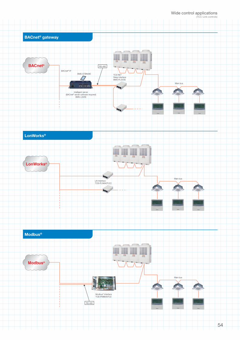
BACnet® gateway
LonWorks®
Main bus
Main busLN InterfaceTCB-IFLN640TLE2
BMS-STBN08E
Intelligent server(BACnet® server software required)
BMS-LSV6E
BACnet® IP
BACnet®
LonWorks®
TCS-NETRelay InterfaceBMS-IFLSV3E
Main bus
Modbus® InterfaceTCB-IFMB640TLE
RS-485
Modbus®
Modbus®
RS-485
Wide control applications(TCC-Link controls)
54
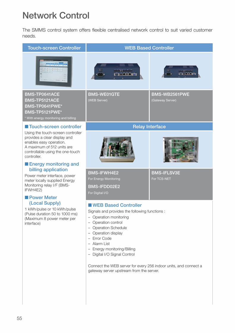
55
The SMMS control system offers flexible centralised network control to suit varied customer needs.
Touch-screen Controller WEB Based Controller
BMS-TP0641ACEBMS-TP5121ACEBMS-TP0641PWE*BMS-TP5121PWE** With energy monitoring and billing
BMS-WE01GTE(WEB Server)
BMS-WB2561PWE(Gateway Server)
n Touch-screen controllerUsing the touch-screen controller provides a clear display and enables easy operation.A maximum of 512 units are controllable using the one-touch controller.
n Energy monitoring and billing application
Power meter interface, power meter locally supplied Energy Monitoring relay I/F (BMS-IFWH4E2)
n Power Meter (Local Supply)
1 kWh/pulse or 10 kWh/pulse (Pulse duration 50 to 1000 ms) (Maximum 8 power meter per interface)
Relay Interface
BMS-IFWH4E2For Energy Monitoring
BMS-IFDD02E2For Digital I/O
BMS-IFLSV3EFor TCS-NET
n WEB Based ControllerSignals and provides the following functions :
– Operation monitoring– Operation control– Operation Schedule– Operation display– Error Code– Alarm List– Energy monitoring/Billing– Digital I/O Signal Control
Connect the WEB server for every 256 indoor units, and connect a gateway server upstream from the server.
Network Control
BACnet®
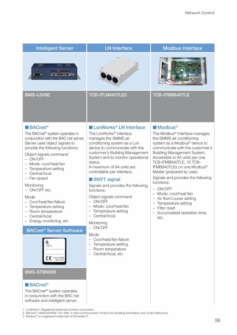
56
1. LonWorks®: Registered trademark Echelon corporation2. BACnet®: ANSI/ASHRAE 135-1995, A data Communication Protocol for Building Automation and Control Networks.3. Modbus® is a registered trademark of Schneider E.
Intelligent Server LN Interface Modbus Interface
BMS-LSV6E TCB-IFLN640TLE2 TCB-IFMB640TLE
n BACnet®
The BACnet® system operates in conjunction with the BAC net server.Server uses object signals to provide the following functions:
Object signals command– ON/OFF– Mode: cool/heat/fan– Temperature setting– Central/local– Fan speed
Monitoring– ON/OFF etc.
Mode– Cool/heat/fan/failure– Temperature setting– Room temperature– Central/local– Energy monitoring, etc.
n LonWorks® LN InterfaceThe LonWorks® interface manages the SMMS air conditioning system as a Lon device to communicate with the custormer’s Building Management System and to monitor operational status.A maximum of 64 units are controllable per interface.
n SNVT signalSignals and provides the following functions:
Object signals command– ON/OFF– Mode: cool/heat/fan– Temperature setting– Central/local
Monitoring– ON/OFF
Mode– Cool/heat/fan/failure– Temperature setting– Room temperature– Central/local, etc.
n Modbus®
The Modbus® interface manages the SMMS air conditioning system as a Modbus® device to communicate with the custormer’s Building Management System.Accessible to 64 units per one TCB-IFMB640TLE, 15 TCB-IFMB640TLEs on one Modbus® Master (prepared by user).
Signals and provides the following functions:
– ON/OFF– Mode: cool/heat/fan– Air flow/Louver setting– Temperature setting– Filter reset– Accumulated operation time,
etc.
BACnet® Server Software
BMS-STBN08E
n BACnet®
The BACnet® system operates in conjunction with the BAC net software and intelligent server.
Network Control
BACnet®

57
1 SETTING displayDisplayed during setup of the timer, etc.
2 Operation mode select displayThe selected operation mode is displayed.
3 CHECK displayDisplayed while the protective device works or a problem occurs.
4 Timer time displayTime of the timer is displayed.(When a problem occurs, the check code is displayed.)
5 Timer SET IN setup displayWhen pushing the Timer SET IN button, the display of the timer is selected in order of [OFF] → [OFF] repeat OFF timer → [ON] → No display.
6 Filter displayIf “FILTER ” is displayed, clean the air filter.
7 TEST run displayDisplayed during a test run.
8 Louver position displayDisplays louver position.
9 SWING displayDisplayed during up/down movement of the louver.
10 Set up temperature displayThe selected set up temperature is displayed.
11 Remote controller sensor displayDisplayed while the sensor of the remote controller is used.
12 PRE-HEAT displayDisplayed when the heating operation starts or defrost operation is carried out.While this indication is displayed, the indoor fan stops.
21 button (Air volume select button)Selects the desired air volume mode.
22 button (Timer set button)TIMER SET button is used when the timer is set up.
23 button (Check button)The CHECK button is used for the check operation. During normal operation, do not use this button.
24 button (Ventilation button)Ventilation button is used when a fan which is sold separately is connected.•If“Nofunction ” is displayed
on the remote controller when pushing the Ventilation button, a fan is not connected.
25 button (Filter reset button)Resets (Erases) “FILTER ” display.
26 button (Power-save operation)SAVE button is used for power-save operation. Cannot be used in SMMSs.
27 button (Swing/Wind direction button)Selects automatic swing or setting the louver direction.
28 Operation lampLamp is lit during operation. Lamp is off when stopped.The lamp flashes when operating the protection device or abnormal time.
13 No function displayDisplayed if there is no function even if the button is pushed.
14 Air volume select displayThe selected air volume mode is displayed.(AUTO) (HIGH) (MED.) (LOW)
15 Louver Number display(example: 01, 02, 03, 04)
16 Dry operation in self-cleaning functionDisplayed during dry operation in self-cleaning function.
17 Power-saving mode displayDisplayed during capacity saving mode by temporary peak-cut limiting the power current level of the outdoor unit.
18 Louver lock displayDisplayed when there is a louver-locked unit in the group (including 1 indoor unit by 1 outdoor unit).
19 Unit Number displayUnit number of the indoor unit selected with the unit select button or abnormal indicate theindoor/outdoor unit.
20 Central control displayDisplayed when the air conditioner is used under the central control in combination with a central control remote controller.In case the remote controller is disabled by the central control system, flashes . The button operation is not accepted.Even when you push ON/OFF, MODE, or TEMP. button, and the button operation is not accepted.(Settings made by the remote controller vary with the central control mode. For details, refer to the Owner’s Manual of the central control remote controller.)
29 buttonWhen the button is pushed, operation starts, and it stops by pushing the button again.When operation has stopped, the operation lamp and all the displays disappear.
30 button (Operation select button)Selects desired operation mode.
31 button (Unit/Louver select button)Selects a unit number (left) and louver number (right).
UNIT:Selects an indoor unit when adjusting wind direction when multiple indoor units arecontrolled with one remote controller.(4-way air discharge cassette type only)
LOUVER:Selects a louver when setting louver lock or wind direction adjustment independently.
32 button (Set up temperature button)Adjusts the room temperature.Set the desired set temperature by pushing or
.
OPTION:Remote controller sensorUsually the TEMP. sensor of the indoor unit senses the temperature. The temperature surrounding the remote controller can also be sensed.For details, contact the dealer from which you have purchased the air conditioner.
* The RBC-AMT31E does not have a SAVE button. Buttons displayed in photo vary slightly for RBC-AMT31E.
Display section Operation section
Display section
7 8 9
10
1115
12
30
24
31
2913
28
34
65
22
25 23 21
32
2
Operation section
Remote Controller RBC-AMT32E (RBC-AMT31E) (main wired remote controller)
20 16 191 17
27 2614
18
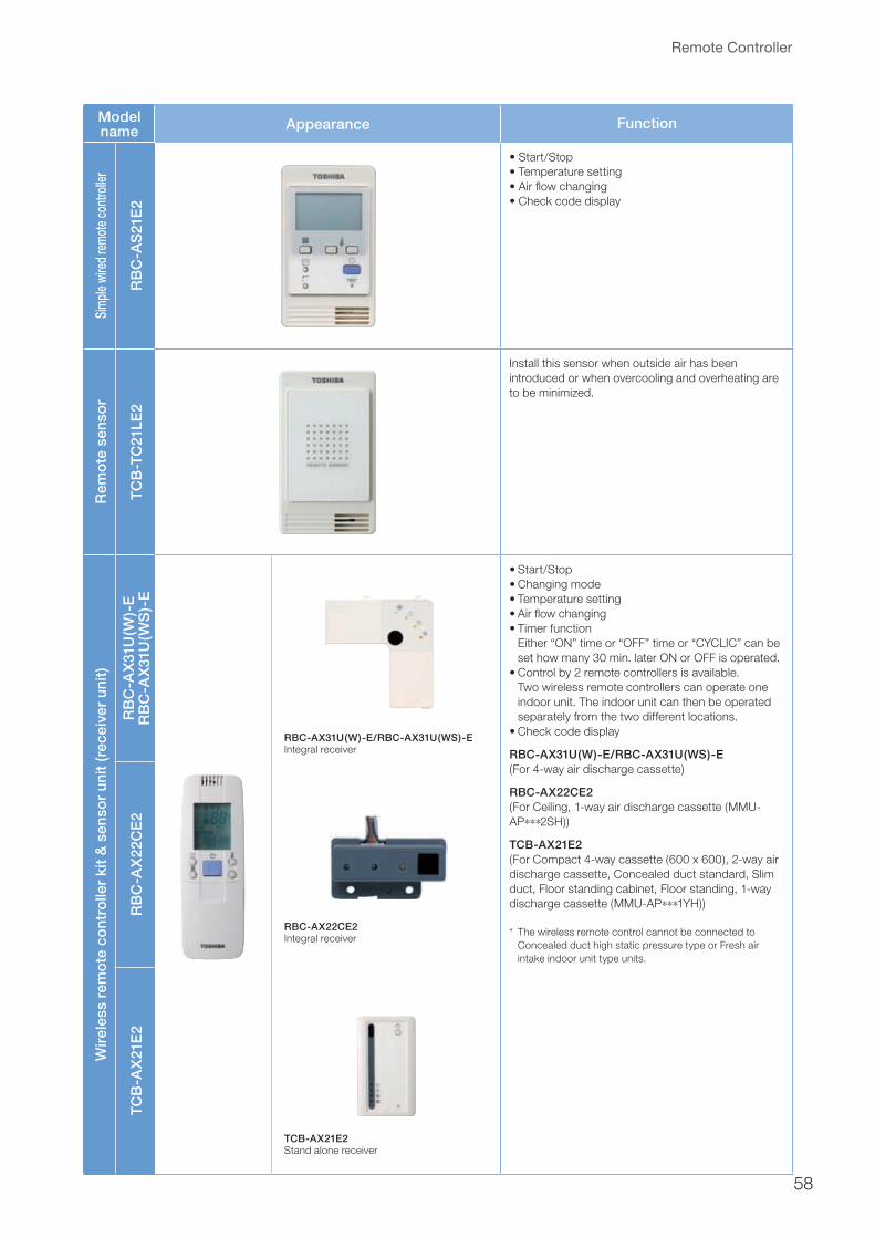
58
Model name Appearance Function
Sim
ple w
ired
rem
ote c
ontro
ller
RB
C-A
S21
E2
•Start/Stop•Temperaturesetting•Airflowchanging•Checkcodedisplay
Rem
ote
sen
sor
TCB
-TC
21LE
2
Install this sensor when outside air has been introduced or when overcooling and overheating are to be minimized.
Wir
eles
s re
mo
te c
ont
rolle
r ki
t &
sen
sor
unit
(rec
eive
r un
it)
RB
C-A
X31
U(W
)-E
RB
C-A
X31
U(W
S)-
E
RBC-AX31U(W)-E/RBC-AX31U(WS)-EIntegral receiver
RBC-AX22CE2Integral receiver
TCB-AX21E2Stand alone receiver
•Start/Stop•Changingmode•Temperaturesetting•Airflowchanging•Timerfunction Either “ON” time or “OFF” time or “CYCLIC” can be
set how many 30 min. later ON or OFF is operated.•Controlby2remotecontrollersisavailable.
Two wireless remote controllers can operate one indoor unit. The indoor unit can then be operated separately from the two different locations.
•Checkcodedisplay
RBC-AX31U(W)-E/RBC-AX31U(WS)-E (For 4-way air discharge cassette)
RBC-AX22CE2 (For Ceiling, 1-way air discharge cassette (MMU-AP∗∗∗2SH))
TCB-AX21E2(For Compact 4-way cassette (600 x 600), 2-way air discharge cassette, Concealed duct standard, Slim duct, Floor standing cabinet, Floor standing, 1-way discharge cassette (MMU-AP∗∗∗1YH))
* The wireless remote control cannot be connected to Concealed duct high static pressure type or Fresh air intake indoor unit type units.
RB
C-A
X22
CE
2TC
B-A
X21
E2
Remote Controller

Model name Appearance Performance
ON
-OF
F c
ont
rolle
r
TCB
-CC
163T
LE2
•Individualcontrolofupto16indoorunits.•Connectionby2remotecontrollersisavailable.•SettingofsimultaneousON/OFF3timesperdaycombined
with the weekly timer.
Cen
tral
rem
ote
co
ntro
ller
TCB
-SC
642T
LE2
•Individualcontrolofupto64indoorunits.
•Individual control for max. 64 indoor units divided into 1 to 4 zone(Up to 16 indoor units for each zone)
•Upto16outdoorheaderunitsareconnectable
•4typesofcentralcontrolsettingstoinhibitindividualoperation by remote controller can be selected
•Settingforoneof1to4zonesisavailable
•Usablewithothercentralcontroldevices (Up to 10 central control devices in one control circuit)
•Twocontrolmodeselectivity
( Central controller mode ) Remote controller mode
•SettingofsimultaneousON/OFF3timesperdaycombinedwith the weekly timer.
Sch
edul
e T
imer
TB
C-E
XS
21T
LE
•Schedule timer mode – 6 programmings per day– Enabling 8 groups to be programmed– A maximum of 64 indoor units can be controlled– A maximum of 100 hours back-up power supply
•Weekly timer mode – 7 types of weekly schedule and 3 programmings per day– Can program off mode by one-minute units
Rem
ote
cont
rolle
r with
wee
kly
timer
(7-d
ay ti
mer
func
tion)
RB
C-A
MS
41E
•Clock display•Schedule timer:Possible to program schedule timer (7-day timer) functionPossible to program 8 functions for each day of the week
* The following items can be set in program: Operation time, Operation start/stop, Operation mode, Temperature setting, Restriction on button operation
Remote Controller
59

Display tenant name where the indoor unit is installed for easier monitoring.
BMS-CM1280TLE, BMS-CM1280FTLE* (Compliant manager)
OperationIndividual operation of 128 indoor units available Return Back OperationWeekly Schedule Operation* (ON/OFF)* Schedule timer necessary
MonitoringZone setting (64 zones x 2)Individual unit operation mode operation restrictionAlarm displayControl inputStatus output
Web Application (BMS-CM1280FTLE)Network connectionSetting Schedule (ON/OFF, Setting temperature, operation mode and Remote control Permit/Prohibit)Error history electrical power distribution* external connection** PC necessary
Up to 128 indoor units can be easily monitored
Easy Schedule Control Can set weekly, monthly schedule
Three-level System Management
Operation Functions
Schedule Operation
System Management
7 days schedule settingCan use the same setting every week to save setting time.
Three-level authorization for multiple user management.
After selecting the day of the week, can set detailed operation setting.•ON/OFFswitch-overatthesettime.•Whenselectingthekeepmode,the
same setting can be continually used.
Holiday settings ahead of time.
Return Back Function for automatic temperature control to maintain the desired fixed temperature.
Restrict user authority by username and password.
Simple checking and setting by clicking each indoor unit.
Easy to check alarm details
* BMS-CM1280FTLE can be connected to Web.
Remote Controller
60
(PC screen)
(PC screen)
(PC screen)
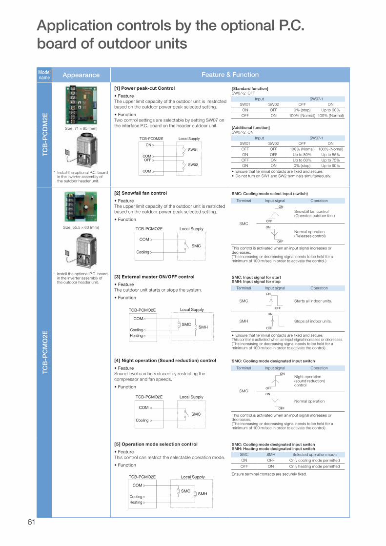
Model name Appearance Feature & Function
TCB
-PC
DM
2E
[1] Power peak-cut Control
•FeatureThe upper limit capacity of the outdoor unit is restricted based on the outdoor power peak selected setting.
•FunctionTwo control settings are selectable by setting SW07 on the interface P.C. board on the header outdoor unit.
ON
COM
SW01
SW02OFF
COM
TCB-PCDM2E Local Supply
Size: 71 × 85 (mm)
* Install the optional P.C. board in the inverter assembly of the outdoor header unit.
TCB
-PC
MO
2E
[2] Snowfall fan control
•FeatureThe upper limit capacity of the outdoor unit is restricted based on the outdoor power peak selected setting.
•Function
COM
Cooling
SMC
TCB-PCMO2E Local Supply
[3] External master ON/OFF control
•FeatureThe outdoor unit starts or stops the system.
•Function
[4] Night operation (Sound reduction) control
•FeatureSound level can be reduced by restricting the compressor and fan speeds.
•Function
COM
Cooling
SMC
TCB-PCMO2E Local Supply
[5] Operation mode selection control
•FeatureThis control can restrict the selectable operation mode.
•Function
COM
CoolingHeating
SMCSMH
TCB-PCMO2E Local Supply
[Additional function]SW07-2 ON
Input SW07-1SW01 SW02 OFF ONOFF OFF 100% (Nomal) 100% (Nomal)ON OFF Up to 80% Up to 85%OFF ON Up to 60% Up to 75%ON ON 0% (stop) Up to 60%
• Ensurethatterminalcontactsarefixedandsecure.• DonotturnonSW1andSW2terminalssimultaneously.
SMC: Cooling mode designated input switchSMH: Heating mode designated input switch
SMC SMH Selected operation mode
ON OFF Only cooling mode permitted
OFF ON Only heating mode permitted
Ensure terminal contacts are securely fixed.
[Standard function]SW07-2 OFF
Input SW07-1SW01 SW02 OFF ON
ON OFF 0% (stop) Up to 60%OFF ON 100% (Normal) 100% (Normal)
SMC: Input signal for startSMH: Input signal for stop
Terminal Input signal Operation
SMC
ON
OFF
Starts all indoor units.
SMH
ON
OFF
Stops all indoor units.
• Ensurethatterminalcontactsarefixedandsecure.This control is activated when an input signal increases or decreases.(The increasing or decreasing signal needs to be held for a minimum of 100 m/sec in order to activate the control).
SMC: Cooling mode designated input switch
Terminal Input signal Operation
SMC
ON
OFF
Night operation (sound reduction) control
ON
OFF
Normal operation
This control is activated when an input signal increases or decreases. (The increasing or decreasing signal needs to be held for a minimum of 100 m/sec in order to activate the control).
SMC: Cooling mode select input (switch)
Terminal Input signal Operation
SMC
ON
OFF
Snowfall fan control (Operates outdoor fan.)
ON
OFF
Normal operation (Releases control)
This control is activated when an input signal increases or decreases. (The increasing or decreasing signal needs to be held for a minimum of 100 m/sec in order to activate the control.)
Size: 55.5 × 60 (mm)
* Install the optional P.C. board in the inverter assembly of the outdoor header unit.
Application controls by the optional P.C. board of outdoor units
COM
CoolingHeating
SMCSMH
TCB-PCMO2E Local Supply
61
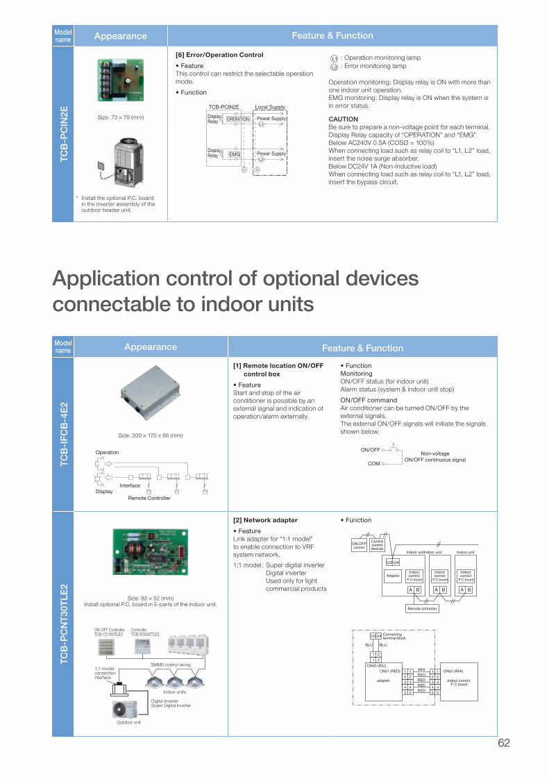
Model name Appearance Feature & Function
TCB
-PC
IN2E
[6] Error/Operation Control
•FeatureThis control can restrict the selectable operation mode.
•Function
TCB-PCIN2E Local Supply
OPERATION
EMG Power Supply
Power SupplyL1
L2
DisplayRelay
DisplayRelay
L1 : Operation monitoring lampL2 : Error monitoring lamp
Operation monitoring: Display relay is ON with more than one indoor unit operation. EMG monitoring: Display relay is ON when the system is in error status.
CAUTIONBe sure to prepare a non-voltage point for each terminal.Display Relay capacity of “OPERATION” and “EMG”Below AC240V 0.5A (COSØ = 100%)When connecting load such as relay coil to “L1, L2” load, insert the noise surge absorber.Below DC24V 1A (Non-inductive load)When connecting load such as relay coil to “L1, L2” load, insert the bypass circuit.
Size: 73 × 79 (mm)
* Install the optional P.C. board in the inverter assembly of the outdoor header unit.
Model name Appearance Feature & Function
TCB
-IFC
B-4
E2
Size: 200 × 170 × 66 (mm)
Operation
DisplayInterface
Remote Controller
[1] Remote location ON/OFF control box
•FeatureStart and stop of the air conditioner is possible by an external signal and indication of operation/alarm externally.
•FunctionMonitoring ON/OFF status (for indoor unit) Alarm status (system & indoor unit stop)
ON/OFF command Air conditioner can be turned ON/OFF by the external signals. The external ON/OFF signals will initiate the signals shown below.
COM
ON/OFFNon-voltage
ON/OFF continuous signal
TCB
-PC
NT
30T
LE2
[2] Network adapter
•FeatureLink adapter for “1:1 model” to enable connection to VRF system network.
1:1 model: Super digital inverter Digital inverter Used only for light commercial products
•Function
Centralcontroldevices
ON-OFFcontrol
Indoorcontrol
P.C.board
Indoor unitIndoor unit
Indoorcontrol
P.C.board
Remote controller
Adaptor
U3 U4
A B A B
Indoor unit
Indoorcontrol
P.C.board
A B
U3 U4
1 2
1 2
1 12 23 34 45 5
1 12 23 34 45 5
WHI
BLU
Connectingterminal block
CN40 (BIU)
CN51 (RED)
adapter
CN50 (WHI)
Indoor control P.C.board
BLU
REDREDREDRED
Size: 85 × 52 (mm) Install optional P.C. board in E-parts of the indoor unit.
SMMS control wiring
Outdoor unit
Digital InverterSuper Digital Inverter
ON-OFF ControllerTCB-CC163TLE2
ControllerTCB-SC642TLE2
1:1 modelconnectioninterface
Indoor units
Application control of optional devices connectable to indoor units
62


![Atlantic Carrier Specifications Sept 2014[4]atlantic-marine.co.uk/.../Atlantic-Carrier-Specifications-Sept-2017... · Atlan&c Carrier Originally built as special Pipe Carrier and](https://img.dokumen.tips/doc/110x75/5afd02cb7f8b9a864d8ce4da/atlantic-carrier-specifications-sept-20144atlantic-carrier-originally-built-as.jpg)