Embed Size (px)
DESCRIPTION
This Document provides a whole lot of information about working in a carpentry shop
Citation preview

UNIT 1 .- . CARPENTRY
Structure
1.1 Introduction
Objectives
1.2 Timber
1.2.1 Market Sizes of Tiniber
1.2.2 ClassificiiLion of Wood
1.2.3 Some Common Timber and Their Characteristics~ses
1.2.4 Felling and Seasoning of Wood
1.2.5 Character-istics of Good Timber
1.3 Carpentry Tools
1.3.1 Marking and Measuring 7'ot)ls
1.3.2 Holding Tool\
1.3.3 Planning T(:cll\
1.3.1 Cutting Touls
1.3.5 Chisels
1.3.6 Drilling and Boring Tools
1.3.7 Miscellanec~us Tools
1.4 Wood Working Procedure
1.4.1 Selection and Laying Out
1.4.2 Marking
1.4.3 Planning
1.4.4 Chiscling
1 4.5 Drilling of Boring Holes
1.5 Wood Joints
I 5.1 Tap Joints
1.5.2 Mortise and Tenon loint
1.5.3 Bridle loint
1.6 Aljaterial Selection
1.7 Joinery Materials
I .7.1 Adhesives
1.7.2 Nails
1.7.3 Wood Screws
1.7.4 Bolts and Nuts
1.7.5 Dowels and Pegs
1.8 Safe Practices and Maintenance of Tools
Carpentry is described as the technological process of making wooden components. It starts from a marketable fonn of wood and ends with a formation of useful value added finished product. The carpentry plays a vital role in the field of building work, furniture, cabinet-manufacturing, interior decoration, toy manufacturing and so forth. Joinery, the making of joints is one of the significant operations in all wood works.

Workshop Technology Objectives Laboratory
After going through this chapter you must be able to
understand the process of converting timber to wood,
identify and apply all the tools of carpentry,
perform all carpentry operations such as marking, planing, cutting, chiseling, and finishing,
make various types of joints, and
make different types of wooden patterns used for foundrylmoulding.
1.2 TIMBER
Timber is the name given to the wood obtained from well grown trees. The trees are cut, sawn into various sizes to suit the purposes.
The word, 'grain', as applied to wood, refers to the appearance or pattern of the wood on the cut surfaces. The grain of the wood is a fibrous structure and to make it strong, the timber must be so cut, that the grains run parallel to the length.
1.2.1 Market Sizes of Timber
Timber is sold in the market in various standard shapes and sizes. The following are common shapes and sizes :
Log The trunk of the tree, free from branches.
Block
The log, sawn to have roughly squarelrectangular cross-section.
Post
A round or square cross-section timber piece with diameter or side, varying from 175 to 300 mrn.
Plank
A sawn timber piece, with more than 275mm in width, 50 to 150 in thickness and 2.5 to 6.5 meters in length.
Board
A timber piece sawn below 50 mm thickness and more than 125 mm in width.
Batten
A timber piece swan below 175 mm in width and 30 to 50 mm in thickness.
Scantlings or Reapers
Sawn timber pieces of assorted and non-standard sizes those may not confirm to the above shapes and sizes.
Beadings
Assorted timber pieces with small thickness with rectangular or square or any designed cross section intended to use as the borders and frames.
1.2.2 Classification of Wood
Woods are generally classified into two broad categories : Soft woods and Hard woods.
Hard and Soft Wood
Hard wood is generally obtained from a tree with deciduous or broad leaves whereas the soft wood from trees having middle shaped conifers.

Carpentry Examples
Hard Woods
Teak, Sal, Oak, Shisham, Beach, Ash. Mango, Neem and Babul.
Soft Woods
Conifers, Kari, Deodar, Chir, Walnut, etc.
Soft wood is light in colour and weight. It is easy to work on soft wood, but it is less durable. Hard wood is dark in colour and heavy in weight. It is very difficult to work on hard wood, but it is highly durable.
Differences between Hard and Soft Wood
S1. No.
1 .
2.
3.
4.
5.
6. 1
7.
8.
9.
10.
1.2.3 Some Common Timber and their Characteristics~Uses
The common type of well recognised timber available in India is Shisham, Sal, Teak, Deodar, Mango, Mahogany, Kail, Chid, Babul, etc. Some of the other foreign wood used in India is Ash, Burma, Hickory, Oak, and Pine.
Shisham
It is dark brown in ccilour and possesses goldenldark brown stripes. It is very hard to work. It wears or blunts the sharp edge of cutting tool very soon. It is abundant in India in Himalayas at the height range of 1000 to 1500 meter and in deep forests. It is highly strong durable wood and is mainly used for making of furniture, tool handles, beds, cabineta, plywood, etc.
Sal
It is in rose brown colour and slowly turns into dark brown colour. This is highly available in India in H~malayas, Madhya Pradesh, Chatthis Garh and Uttar Pradesh. Tt is free from attack of white ants and is very difficult to work. It has poor finish and therefore is not used for decorative furniture but it finds applications in making doors, windows, cot?, wooden handles where finish is not important.
Teak Wood
Tt is the most common wood used in variety of applications. This wood is abundantly available in Andhra kadesh, Madhya Pradesh, Chatthis Garh, Orissa, West Bengal and Assam. It is mainly used for making good quality of furniture, Constructions (doors/windows), plywood, ships, etc. This wood is supposed as the KING of woods. Some of it? features are :
(a) Hard,
(b) Very costly but wide appllcat~ons. 7
Characteristics
Colour
Weight
Density
Resin Content
Ab~lity to Split
Workability
Annual Rings
Tensile and Shear Resistance
Fire catching
Growth
Hard Wood
Dark
Heavy
Denser
Less
Does not split quickly
Difficult
Close and indistinct
Good tensile and shear resistance
Doesn't catch fire soon
Slow growing
Soft Wood
Light
Light
Comparatively light
Few soft wood are resinous
Gets spl~t quickly
Easy
Well spaced and d~stinct
Good tensile resistance but weak acros3 the fibers
Catches fire very soon
Fast growing

Workshop Technology Laboratory
(c) It is available in golden yellow or dark brown colour,
(d) Special stripes on it add to its beauty,
(e) Very strong and durable, and
(f) It maintains good polish.
Deodar
It is white in colour when soft but turns to light yellow as it becomes hard. It is strong and durable. It provides fragrance when smelt. It is not easily attacked by insects. Its common availability is in Himalayas at a height from 1500 to 3000 mts. It is used for making furniture, windows, etc.
Mango
It is Brown in colour and can be easily shaped in various products. It is widely used in India for making doors packing cases, toys, etc. as a chief products.
Mahogany
It is reddish brown in colour and is highly durable when dry? It also contains some oil that prevents it from the attack of insects. It is generally used for manufacturing cabinet, fine furniture, pattern making work, etc.
Kail
This wood possesses too many knots. It is commonly found in Himalayas. It yields a close grained moderately hard and durable wood which can be easily painted. It is commonly utilized for making cheap furniture, wooden door, paclung case, etc.
Chid or Chir
Its colour is dark brown when soft, but it is reddish brown when hard. It has stripes of brown colour. It has oily smell and is used for interior work in the house.
Babul
It is close grained tough and pale red coloured wood used for making tool handles, etc.
Fir Wood
It is light brown in colour when it is soft but harder variety is in dark brown. It can be easily attacked by insects. It is commonly utilizes for making drawers, packing cases door, etc.
Walnut
It is a good variety of wood which resists the attack of white ants. It can be polished in a better way. This wood is generally used for making musical instruments, furniture cabinet work, and decoration work.
Haldu
It is white in colour at the time of cutting, but once cut, its colour becomes yellow. It can be dried polished satisfactorily. It is widely used for making small objects such as stools, trays, picture frames, cabinets, etc.
Neem
This is whitish brown in colour and is free from white ants and insects. It is comparatively hard. It has poor finish ability. Widely available in Andhra Pradesh, Deccan plateau and Mid-India.
1.2.4 Felling and Seasoning of Wood
Conversion of tree into timber or wood logs is called felling. A newly felled tree contains considerable moisture content. If this is not removed, the timber is likely to wrap, shrink, crack or decay. Seasoning is the art of extracting the moisture content under controlled conditions, at a uniform rate, from all parts of the timber. Only seasoned wood should be

used for all carpentry works. Seasoning makes the wood resilient and lighter. The seasoning is carried out into two ways, viz. Natural seasoning and artificial seasoning. Hot air or water is used for seasoning.
Carpentry
1.2.5 Characteristics of Good Timber
A good timber should
(a) Have minimum moisture content, i.e. it should be well seasoned.
(b) Have straight and long grains.
(c) Retain its straightness after seasoning.
(d) hoduce a characteristic sound (nearly metallic) on hammering.
(e) Be free from defects such as knots, cracks, rind galls, shakes and twists.
(0 Have uniform colour throughout.
(g) Respond well to the finishing and polishing operations.
(h) Not split easily during driving the nails and screws.
1.3 CARPENTRY TOOLS --
The following are the tools used in wood working operations :
1.3.1 Marking and Measuring Tools
To produce parts to exact size we need to do marking first. To transfer dimensions onto work; the following are the marking and measuring tools that are generally used in carpentry.
Steel Rule
It is an important tool for linear measurement and can also be used as a marking tool.
Figure 1.1 : Steel Rule
Steel Tape
It is used for large measurements, such as marlung on boards and checking the over all dimensional of the work.
Marking Gauge
Marking gauge is a tool used to mark lines parallel to the edge of a wooden piece. It consists of a square wooden stem with a sliding wooden stem with a sliding wooden stock (head) on it. On the stem is fitted with a marking pin, made of steel. The stock is set at desired distance from the marking point and fixed in position by a screw. It must be ensured that marking pin projects through the stem 3mm and the end is sharp enough to make a very fine line.

Workshop Technology Mortise Gauge Laboratory
A mortise gauge consists of two pins. In this, it is possible to adjust the distance between the pins, to draw two parallel lines on the stock.
(a) Marking Gauge (b) Mortise Gauge
Figure 1.2 : Mortise Gauge
It is used for making and testing the straightness and squareness (perpendicularity) of planed surfaces. It consists of a steel blade, fitted in a cast iron stock. It is also used for checking the planed surfaces for flatness. Its size varies from 150 to 300 mm, according to the length of the blade.
Testing for Straightness
Testing for Squareness
Figure 1.3 : Try-square
Compass and Divider
These are used for marking arcs and circles on the planed surfaces of the wood.
Scriber or Marking Knife
It is used for marking on timber. It is made of steel, having one end pointed and the other end formed into a sharp cutting edge.
Scriber or Making Knife
Blade
Compass Divider
Figure 1.4 : Scriber or Marking Knife
It is used for laying-out and checking angles. The blade of the bevel is adjustable and may be held in place by a thumb screw. After it is set to the desired angle, it can be used in same way as a try-square. The extra advantage of this over try square is that it can be adjusted at any angle while try square can check only perpendicularity only. A good way to set it to the required angle is to mark the angle on a surface and then adjust the blade to fit the angle.

1.3.2 Holding Tools
Carpenter's Vice
The carpenter's bench vice, used as a work holding device in a carpenter shop. Its one jaw is fixed the side of the table while the other is movable by means of the screw and a handle. The jaws are lined with hard wooden faces.
t9 '\,, Trigger for Qulck Openlng
Figure 1.5 : Carpenter's Vice
C-clamp is used for holding small works.
Bar Clamp * .
A bar clamp as shown in the following figure is made of steel bar of T-section, with malleable iron fitting and a steel screw. It is used for holding wide works such as frames or tops.
Retaining Pin
Figure 1.6 : Bar Clamp
1.3.3 Planing Tools
Planing is the operation carried out on wood to produce flat surfaces. A plane is a hand tool used for this purpose. The cutting blade of a plane is fitted in a wooden or metallic block, at an angle. This cutting blade used in a plane is similar to a chisel. Different types of planes used for different purposes are shown here below.
Jack Plane
It is the most commonly used general purpose plane. It is about 30-40 cm lobg. The cutting blade has a cutting edge of slight curvature for quick removal of material on rough work and is also used in oblique planning,
I I
Workshop Technology Rebate Plane Laboratory
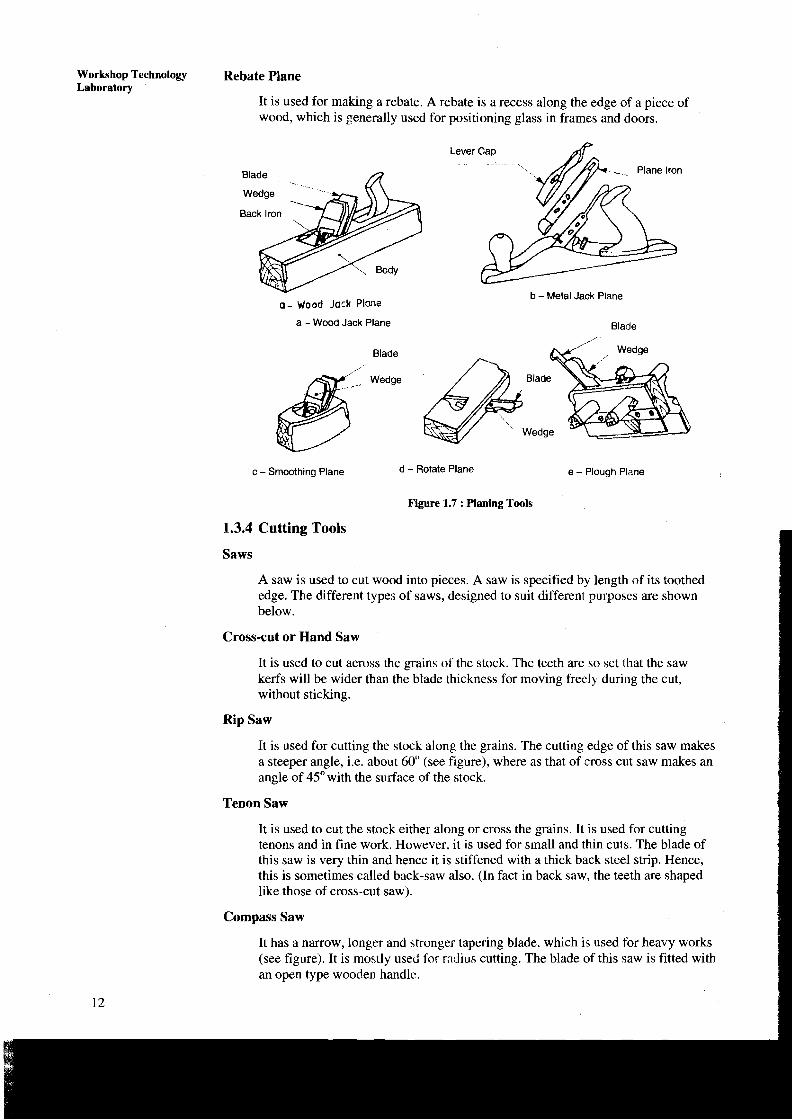
It is used for making a rebate. A rebate is a recess along the edge of a piece of wood, which is generally used for positioning glass in frames and doors.
Blade .. .
o- Wood Jock Plane
Lever Cap . . .. .. . .
b - Metal Jack Plane
a -Wood Jack Plane Blade
Blade
c - Smoothing Plane d - Rotate Plane e - Plough Plane
Figure 1.7 : Planing Tools
1.3.4 Cutting Tools
Saws
A saw is used to cut wood into pieces. A saw is specified by length of its toothed edge. The different types of saws, designed to suit different purposes are shown below.
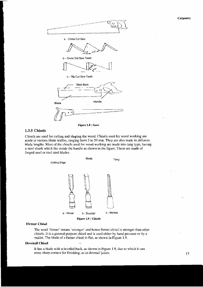
Cross-cut or Hand Saw
It is used to cut across the grains of the stock. The teeth are so set that the saw kerfs will be wider than the blade thickness for moving free11 during the cut, without sticking.
Rip Saw
It is used for cutting the stock along the grains. The cutting edge of this saw makes a steeper angle, i.c. about 60" (see figure), where as that of cross cut saw makes an angle of 45" with the surface of the stock.
Tenon Saw
It is used to cut the stock either along or cross the grains. It is used for cutting tenons and in fine work. However, it is used for small and thin cuts. The blade of this saw is very thin and hence it is stiffened with a thick back steel strip. Hence, this is sometimes called back-saw also. (In fact in back saw, the teeth are shaped like those of cross-cut saw).
Compass Saw
It has a narrow, longer and btronger tapering blade, which is used for heavy works (see figure). It is mostly used for radius cutting. The blade of this saw is fitted with an open type wooden handlc.
Carpentry
a - Cross Cut Saw
A m -?C
b - Cross Cut Saw Teeth
[' 90. -'\ -t 1 - -
c - RIP Cut Saw Teeth --- Blade Handle
Figure 1.8 : Saws
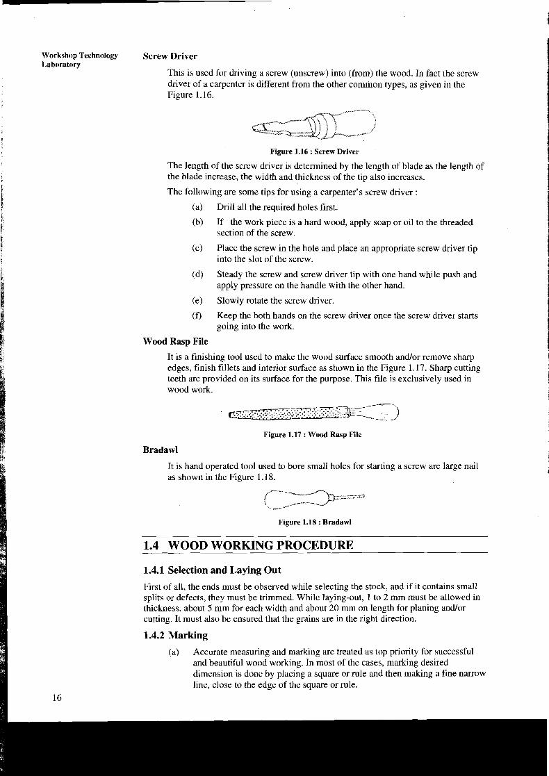
1.3.5 Chisels Chisels are used for cutting and shaping the wood. Chisels used for wood working are made in various blade widths, ranging from 3 to 50 mm. They are also made in different blade lengths. Most of the chisels used for wood working are made into tang type, having a steel shank which fits inside the handle as shown in the figure. These are made of forged steel or tool steel blades.
Blade Tang
Cuttlng Edge
a - Firmer b - Dovetail c - Mort~se
Figure 1.9 : Chisels
Firmer Chisel
The word 'firmer' means 'stronger' and hence firmer chisel is stronger than other chisels. It is a general purpose chisel and is used either by hand pressure or by a mallet. The blade of a firmer chisel is flat, as shown in Figure 1.9.
Dovetail Chisel
It has a blade with a beveled back, as shown in Figure 1.9, due to which it can enter sharp comers for finishing, as in dovetail joints. 13

Workshop Technology Mortise Chisel Laboratory
This is used for cutting mortises and chipping inside holes. The cross-section of the mortise chisel is so proportioned as to withstand heavy blows during mortising (Figure 1.9). Further, the cross-section is made stronger near the shank.
1.3.6 Drilling and Boring Tools
Carpenter's Brace
This is used for rotating auger bits, twist drills, etc., to produce holes in wood as shown in the Figure 1.10. Some braces have ratchet device. With this, holes may be made in a comer where complete revolution of the handle cannot be made. The size of a brace is determined by its sweep.
Figure 1.10
Auger Bit
It is similar to drill bit and is the common tool used for making holes in wood. During drilling, the lead screw of the bit guides into the wood, necessitating only moderate pressure on the braces. The helical flutes on the surface cany the chips to the outer surface (see Figure 1.1 1).
Twist
Scoring Nib
Cutting Tip "
Figure 1.11
Hand Drill Carpenter's Brace
This is used to make relatively large size holes; while hand drill is used for drilling small holes. A straight shank drill is used with this tool. It is small, light in weight and may be conveniently used than the brace. The drill bit is clamped in the chuck at its end and is rotated by a handle associated with gear and pinion mechanism.
Gimlet
It has cutting edges like a twist drill as shown in the Figure I .12. It is used to drill holes of large diameter with the hand pressure.

1.3.7 Miscellaneous Tools
Mallet
A mallet made up of wood or rubber is like a hammer used to drive the chisel with considerable force to be applied, which may be the case in making deep rough cuts (Figure 1.13). SteeVIron hammer should not be used for the purpose, as it may damage the chisel handle. Further, it is advisable to apply a seiies of light taps with the mallet rather than a heavy single blow.
Figure 1.13 : Mallet
Pincer
It is usually made up of two forged steel arms hinged and is used to pull-out small nails from wood. The inner faces of the pincer jaws are beveled and the other faces are plain. The end of one arm has a ball and the other has a claw. The beveled jaws and the claw are used for pulling out small nails, pins and screws from the wood.
Figure 1.14 : Pincer I i Claw Hammer
It has a striking flat face at one end and the claw at the other, as shown in the Figures 1.15. The face is used to drive nails into wood and for other striking purposes and the claw extracting relatively large nails out of the wood. It is usually made up of cast iron.
Carpentry
1 Figure 1.15 : Claw Hammer 15
Workshop Technology Laboratory
Screw Driver
This is used for driving a screw (unscrew) into (from) the wood. In fact the screw driver of a carpenter is different from the other common types, as given in the Figure 1.1 6.
Figure 1.16 : Screw Driver
The length of the screw driver is determined by the length of blade as the length of the blade increase, the width and thickness of the tip also increases.
The following are some tips for using a carpenter's screw driver :
(a) Drill all the required holes first.
(b) If the work piece is a hard wood, apply soap or oil to the threaded section of the screw.
(c) Place the screw in the hole and place an appropriate screw driver tip into the slot of the screw.
(d) Steady the screw and screw driver tip with one hand while push and apply pressure on the handle with the other hand.
(e) Slowly rotate the screw driver.
(f) Keep the both hands on the screw driver once the screw driver starts going into the work.
Wood Rasp File
It is a finishing tool used to make the wood surface smooth and/or remove sharp edges, finish fillets and interior surface as shown in the Figure 1.17. Sharp cutting teeth are provided on its surface for the purpose. This file is exclusively used in wood work.
Figure 1.17 : Wood Ra5p File
Bradawl
It is hand operated tool used to bore small holes for starting a screw are large nail as shown in the Figure 1.18.
Figure 1.18 : Bradawl
1.4 WOOD WORKING PROCEDURE --
i!i 1.4.1 Selection and Laying Out
First of all, the ends must be observed while selecting the stock, and if it contains small splits or defects, they must be trimmed. While laying-out, 1 to 2 mm must be allowed in thickness, about 5 mm for each width and about 20 mm on length for planing and/or cutting. It must also be ensured that the grains are in the right direction.
I 1.4.2 Marking
(a) Accurate measuring and marking are treated as top priority for successful and beautiful wood working. In most of the cases, marking desired dimension is done by placing a square or rule and then making a fine narrow line, close to the edge of the square or rule.
16

Carpentry A soft pencil, that can make a line easily visible, serves the purpose for malung. However, for accurate marking it is advisable to use a blade.
For marking with the help of marking gauge, it must be firmly held with fingers around the head and with the thumb behind the marking point and the gauge must be pushed forward against the surface. While pushing, the gauge should be kept slightly forward so that, the point gets dragged at the slight angle.
If the job requires plane finish, an allowance must be provided for this, while marking. However, it must be kept in mind that removing excess material by a plane is a tedious and difficult job and hence should be kept as minimum as possible.
Laying-out an Angle
The following are the steps involved in laying out an angle on a wooden surface :
(a) Set the bevel to the required angle.
(b) Hold the handle f m l y against the face or edge of the board.
(c) Mark along the edge of the blade with a pencil or knife.
1.4.3 Planing
Plane Adjustment
A plane cannot produce a proper work surface if the blade is not sharp (blunt) and not adjusted properly. There are two adjustments in built in the design of the plane. First one is to regulate the depth of cut and the other is to straighten the blade so that, it produces a flat surface.
The first adjustment of the plane, i.e. depth of cut may be checked by feeling the edges of the blade with the first two fingers. And the second adjustment is checked by trying to movelslide the blade holding at its comers and tightening the screw till it does not move i.e. firmly held.
Figure 1.19 : Plane Adjustment
Method of Using the Plane
The following may be noted while using the plane :
(a) Hold the handle of the plane with the right hand and the knob with the left hand.
(b) Stand to the left side of the job foot apart and with the left foot slightly ahead.
(c) While pushing the plane, gradually shifting weight to the left foot.
(d) While planning, keep the fore-arm straight in-line behind the plane.
(e) Always plane along the grains. Planning against the grains will result in rough work.
(f) When not in use, keep the plane on its side. This prevents the cutting edge becoming dull by contact with the bench top.
17

Workshop Technology Planing a Surface - Laboratory
Planing is the first and foremost operation to be performed on any carpentry job.
The following are the steps involved in planning a surface :
(a) Start at one edge of the stock, plane with full length strokes to the other edge.
(b) Use the edge of the steel rule or try-square to test the surface placing the edge in various positions on the surface and see the underneath gaps to locate high and low piaces. For this, the order of the checking is as follows :
c (i) Place the straight edge cross-wise on the stock and move it slowly form one end to the other.
(ii) Then place the edge lengthwise and move it slowly form one edge to the other.
(iii) Finally place the straight edge on the one diagonal and then on the other.
(c) While planing, if it appears to be cutting at some spot and not in another, it indicates high spots in the surface. So continue to plane these high spots until they disappear and plane takes a shaving across the entire length.
(d) Select the best surface or edge as reference, since defects on the other surface or edge may be removed when the stock is reduced to the required thickness.
Planing End Grain
End grain is hard to plane. So, Jack plane is generally used for this. In this plane, the blade is set at low angle with the bevel side turned up, to make a shearing type of cut. The plane i,s to be held in one hand leaving the other hand free to hold or support the work. The planing should be carried out from both the edge as shown in above Figure 1.19: ,
Squaring Up a stock'
It is necessary in wood work, to plane all the sides and ends, at right angle to adjoining surfaces. A board or stock is considered to be squared. so that all the surfaces/edges/ends are at 90 degree to each other. This may be achieved in the following order :
(a) Plane any one surfade smooth and true: This surface may then be treated as working surface. Mark it with one short line, near thq edge to be selected next.
(b) Select that edge and plane it straight and square with the working surface. This edge is then called the working edge. Use straight edge for testing straightness and squareness. Mark two short lines, extending to the working surface.
(c) Plane the second edge, parallel to the above working edge. For this, mark to the desired width on both the surfaces and then plane to the marked lines.
(d) Mark one end with the square, cut it and make it straight and square with the working surface and the working edges.
1.4.4 Chiseling
The following are the noteworthy points to be observed while chiseling :
(a) Fix the work piece in a vice. Now both hands will become free to use on the chisel.
18

Carpentry 1 * (b) Push the chisel away from the body and keep both the hand? behind the
cutting edge (Figure 1.20).
(c) Use the left-hand to guide the chisel, while the right-hand to push it forward.
(d) Use the chisel with the bevel down for roughing cuts and with the bevel up for finishing cuts.
Chiseling Along the Grains
To reduce either the width or thickness of the stock chiseling is made along the
Chiseling Across the Grain
The chiseling is done across the grains in making notches. The following points must be observed during the work :
(a) Hold the blade of the chisel between the thumb and first two fingers of the left hand and guide it while pushing with the right hand.
(b) Instead of cutting across the entire width, cut the mid way from one edge and then from the other to avoid 3plitting.
(c) Cut with the bevel side up, raising the handle just enough to make the chisel cut.
Chiseling Across end Grains
As far as possible, the chiseling work across the end grains may be avoided by careful marking and sawing leaving about lmm or so (to be removed by chiseling). For this :
(a) Begin on the front edge and push forward at an angle.
(b) Straighten the handle to vertical, towards the end of the stroke.
(c) Guide the chisel with the left hand, while applying force with the right.
(d) It is better to use only about half the width of the chisel for cutting on each stroke, while keeping the remaining half, flat against the surface
- obtained by the previous cut.
(e ) For through cutting, it is advisable to keep a piece of scrap lumber under the stock, to keep the chisel away from cutting into the bench.
Horizontal Chiseling
The following is the procedure for horizontal chiseling :
(a) Fasten the work in a vice or on a bench. ,
(b) Guiding the blade with the thumb and fore fingers of the left hand push the chisel with the right hand.
(c) Make sure that the level of the chisel is turned-up during the work.
The chiseling steps are shown in Figure 1.20. 19

Workshop Technology Vertical Chiseling Laboratory
The following is the procedure for vertical chiseling :
(a) Fasten the work in a vice or a bench.
(b) Hold the flat side of the chisel against the wood in a vertical position.
(c) Guiding the blade with the left hand push the chisel, making a shearing cut with the right hand.
(d) The left hand should also serve as a brake.
(e) Use a mallet to drive the chisel, only when necessary.
1.4.5 Drilling or Boring Holes
To fit screws, bolts, dowels, etc. holes are drilled or bored in wood. The following steps involved are in the drilling process :
(a) Measure and layout the position of the hole by two cross lines on the best face of the stock.
(b) Punch a small hole with a bradawl at the intersecting point of the lines.
(c) Fasten the stock (work) in a vice firmly.
(d) Keep a piece of waste stock that will support the wood, when the bit cuts through.
(e) Select the correct,size bit and insert into the chuck of the brace.
(f) Set the bit on the spot marked for the centre of the hole.
(g) Guide it with the left hand and make few turns in a clockwise direction, with the brace to start the hole.
(h) Check the angle of boring by testing with a try-square against the bit.
(i) Check if the bit and work that should make a right angle.
(j) After boring, remove the bit from the hole, by turning the brace in counter-clockwise direction.
(k) While boring a large hole in a small piece of wood, it is better to apply pressure to the sides of the screw apart of the auger bit to prevent splitting.
Drilling with a Hand Drill
Follow the point given below while using of a hand drill :
(a) Hold the head of the hand drill with left hand guide the drill to the marking and then turn the crank steadily with the hand.
(b) Apply uniform and moderate pressure while drilling.
(c) Too slow or too high.a speed or heavy pressure may break small drill bits.
1.5 WOOD JOINTS
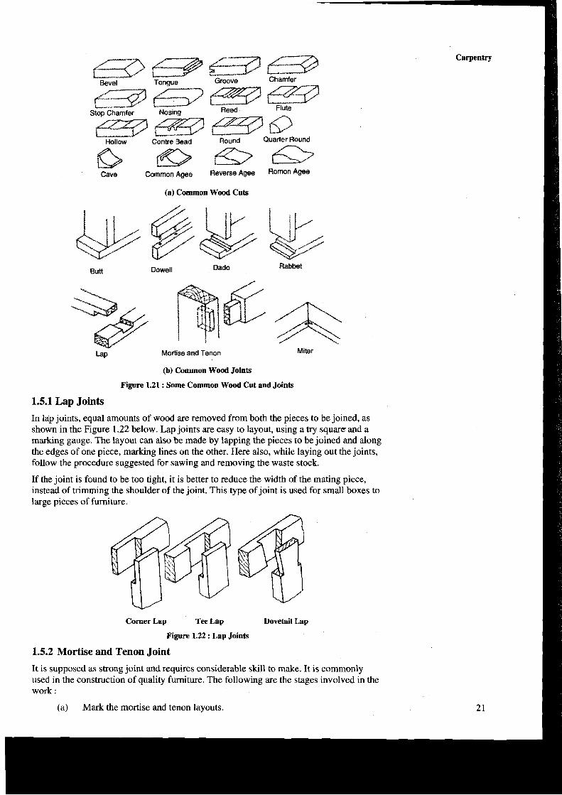
There are several kinds of joints used to join wood stock. Each joint has a definite use and requires laying-out, cutting and putting them together. Of course, the strength of the joint depends upon the amount of contact area, and the reinforcement with nails, screws or dowels, etc. Some commonly used wood cuts and joints are shown in Figure 1.21.
Carpentry
(a) Common Wood Cuts
Butt Dowell Dado Rabbet
Mortise and Tenon
(b) Common Wood Joints
Figure 1.21 : Some Common Wood Cut and Joints
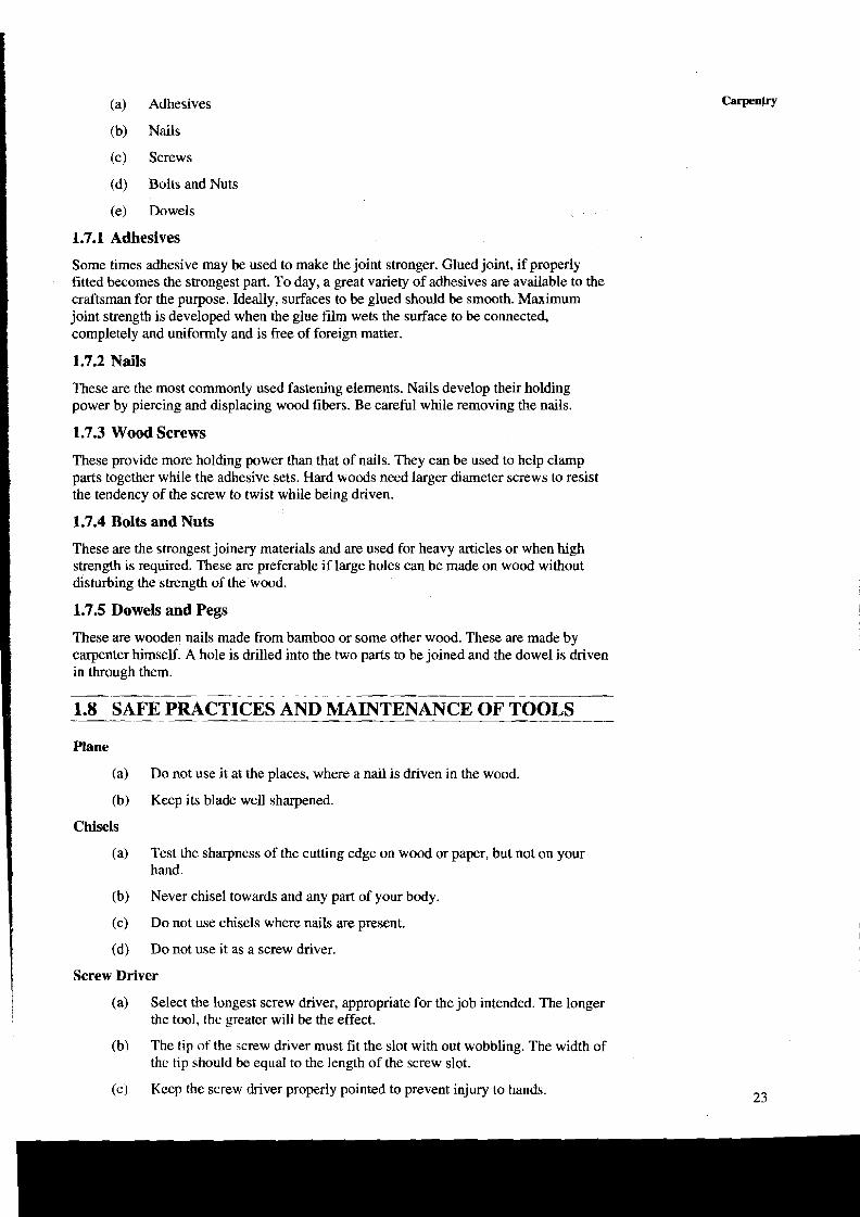
1.5.1 Lap Joints
In lap joints, equal amounts of wood are removed from both the pieces to be joined, as shown in the Figure 1.22 below. Lap joints are easy to layout, using a try square and a marking gauge. The layout can also be made by lapping the pieces to be joined and along the edges of one piece, marking lines on the other. Here also, while laying out the joints, follow the procedure suggested for sawing and removing the waste stock.
If the joint is found to be too tight, it is better to reduce the width of the mating piece, instead of trimming the shoulder of the joint. This type of joint is used for small boxes to large pieces of furniture.
Comer Lap Tee Lap Dovetail Lap
Figure 1.22 : Lap Joints
1.5.2 Mortise and Tenon Joint
It is supposed as strong joint and requires considerable skill to make. It is commonly used in the construction of quality furniture. The following are the stages involved in the work :
(a) Mark the mortise and tenon layouts.

Workshop Technology (b) Cut the mortise first by drilling a series of holes within the layout lines, Laboratory chiseling out the waste stock and trimming the corners and sides.
\ (c) Prepare the tenon by cutting and chiseling.
(d) Check the tenon size against the mortise that has been prepared and adjusted it if necessary.
Plain Tenon Bare Faced Tenon Divided Tenon
Figure 1.23 : Mortise and Tenon Joint
1.5.3 Bridle Joint
This can be considered as the reverse of mortise and tenon joint in form. Therefore, the marking and layout of the joint is the same as for mortise and tenon joint. This joint is used where the members are of square or near square section and suitable for mortise and tenon joint. Different kinds of bridle joints are shown in the Figure 1.24.
Comer Bridle Tee Bridle Mitrefaced Bridle
Figure 1.24 : Bridle Joint
1.6 MATERIAL SELECTION
The ease of fabrication is directly related to the quality of the material used. The following are the guidelines for material selection :
(a) Select well seasoned wood to avoid warping problems later.
(b) Examine the areas close to the ends of the piece for cracks/shakes/rind galls/twists, etc. These defects pose a problem for a good job.
(c) Avoid piece with knots. These areas are difficult to work.
(d) If possible select straight grained pieces.
1.7 JOINERY MATERIALS
The joinery materials are used to join the processed/finished wooden pieces or wooden pieces with other materials. The common joinery materials used in practice are :
(a) Adhesives
(b) Nails
(c) Screws
(d) Bolts and Nuts
(e) Dowels
1.7.1 Adhesives
Some times adhesive may be used to make the joint stronger. Glued joint, if properly fitted becomes the strongest part. To day, a great variety of adhesives are available to the craftsman for the purpose. Ideally, surfaces to be glued should be smooth. Maximum joint strength is developed when the glue film wets the surface to be connected, completely and uniformly and is free of foreign matter.
1.7.2 Nails
These are the most commonly used fastening elements. Nails develop their holding power by piercing and displacing wood fibers. Be careful while removing the nails.
1.7.3 Wood Screws
These provide more holding power than that of nails. They can be used to help clamp parts together while the adhesive sets. Hard woods need larger diameter screws to resist the tendency of the screw to twist while being driven.
1.7.4 Bolts and Nuts
These are the strongest joinery materials and are used for heavy articles or when high strength is required. These are preferable if large holes can be made on wood without disturbing the strength of the wood.
1.7.5 Dowels and Pegs
These are wooden nails made from bamboo or some other wood. These are made by carpenter himself. A hole is drilled into the two parts to be joined and the dowel is driven in through them.
1.8 SAFE PRACTICES AND MAINTENANCE OF TOOLS --
Plane
(a) Do not use it at the places, where a nail is driven in the wood.
(b) Keep its blade well sharpened.
Chisels
i (a) Test the sharpness of the cutting edge on wood or paper, but not on your
I hand. I i (b) Never chisel towards and any part of your body.
(c) DO not use chisels where nails are present.
(d) Do not use it as a screw driver.
Screw Driver
(a) Select the longest screw driver, appropriate for the job intended. The longer the tool, the greater will be the effect.
(b) The tip of the screw driver must fit the slot with out wobbling. The width of the tip should be equal to the length of the screw slot.
(c) Keep the screw driver properly pointed to prevent injury to hands.

Workshop Technology Saws Laboratory
(a) Do not use a saw with a lose handle.
(b) Always use a triangular file for sharpening the teeth.
(c) Apply grease when not in use.
(d) Do not use a saw on metallic substances.
Mallet
(a)
(b)
Auger Bit
(a)
(b)
Bradawl
(a)
(b)
General
(a>
(b)
Do not use it on hard substances.
Do not use it on nails.
Do not use it with out a handle.
Keep it straight while drilling; other wise, the screw positions may get altered.
Keep it well sharpened.
Do not use it on metals.
Tools not in use should always be kept at their proper places.
Ensure that your hands are not in front of the sharp edged tools while you work with them.
Use only sharp tools, otherwise sharpen.
A dull or blunt tool requires excessive pressure (or consumes more power) and also causes slip.
Wooden piece with nails should never be allowed to remain on the floor.
Take care, when you use your thumb as a guide in cross-cutting and ripping.

EXPERIMENT NO. 1 : T-LAP JOINT Exercise
To prepare a T-lap joint as shown in Figure 1.25(b).
Carpentry
Wooden reaper of size 75 x 50 x 300 mrn.
Tools Required
(a) Carpenter's vice
(b) Steel rule
(c) Jack plane
(d) Try-square
(e) Working gauge
(f) 25 mm firmer chisel
(g) Cross-cut saw
(h) Tenon saw
(i) Scriber
(i) Mallet.
Sequence of Operations
(a) The wooden reaper is checked for its actual size. Measure all the dimensions with a steel rule.
(b) The wooden part is clamped in the carpenters vice and any two adjustment faces are planned Jack plane and by faces are checked for squareness with the try-square.
(c) With making gauge, mask the thickness and width of the wooden block to the 40 and 60 mm size.
(d) With firmer chisel, the excess material is removed. Then with jack plan, planed the surfaces to the correct size.
(e) The mating dimensions of the part X and Yare then marked using scale and marking gague. 25

Workshop Technology Labomtory
Q As shown in the Figure 1.25(a) wooden part is cut into two parts according to the dimensions (i.e. 150 mm and 150 mm) with cross-cut saw.
(g) With cross-cut saw, the mating portions to be removed are cut in both the pieces (i.e. 60 x 20 rnm).
(h) The ends of both the parts are chiseled to the exact lengths.
(i) A fine finishing is given to the parts, if required so that proper fitting is obtained.
Cj) The parts are fitted to obtain a slightly tight joint.
Result
The T-lap joint is prepared.

Carpentry
EXPERIMENT NO. 2 : DOVERTAIL LAP JOINT
Exercise
To prepare a dovetail lap joint as shown in Figure 1.26.
Figure 1.26 : Dovertail Lap Joint
Raw Material
Wooden reaper of size 75 x 50 x 300 mm.
Tools Required
(a) Carpenter's vice
(b) Steel rule
(c) Jack plane
(d) Try-square
(e) Working gauge
(f) 25 rnm firmer chisel
(g) Cross-cut saw
(h) Tenon saw
(i) Scriber
(j) Mallet.
Sequence of Operations
(a) The wooden reaper is checked for its actual size. Measure all the dimensions with a steel rule.
(b) The wooden part is clamped in the carpenters vice and any two adjustment faces are planed by faces are checked for squareness with the try-square.
(c) With making gauge, mask the thickness and width of the wooden block to the 40 and 60 rnrn size.
27

Workshop Technology (d) With firmer chisel, the excess material is removed. Then with jack plan, Laboratory planed the surfaces to the correct size.
(e) The mating dimensions of the part X and Yare then marked using scale and marking gauge.
( f ) As shown in the Figure 1.25(a) wooden part is cut into two parts according to the dimensions (i.e. 150 mm and 150 rnm) with cross-cut saw.
(g) With cross-cut saw, the mating portions to be removed are cut in both the pieces (i.e. 60 x 20 mm).
(h) The ends of both the parts are chiseled to the exact lengths.
(i) A fine finishing is given to the parts, if required so that proper fitting is obtained.
(i) The parts are fitted to obtain a slightly tight joint.
Result
The dovetail lap joint is prepared.

EXPERIMENT NO. 3 : CORNER JOINT
Exercise
To prepare a comer joint as shown in Figure 1.27.
Figure 1.27 : Corner Joint
Raw Material
Wooden reaper of size 75 x 50 x 300 mm.
Tools Required
(a) Carpenter's vice
(b) Steel rule
(c) Jack plane
(d) Try-square
(e) Working gauge
( f ) 25 mm firmer chisel
(g) Cross-cut saw
(h) Tenon saw
(i) Scriber
(j) Mallet.
Sequence of Operations
(a) The wooden reaper is checked for its actual size. Measure all the dimensions with a steel rule.
(b) The wooden part is clamped in the carpenters vice and any two adjustment faces are planned by faces are checked for squareness with the try-square.
(c) With making gauge, mask the thickness and width of the wooden block to the 40 and 60 rnm size.
(d) With firmer chisel, the excess material is removed. Then with jack plan, planed the surfaces to the correct size.
(e) The mating dimensions of the part X and Yare then marked using scale and marking gauge.
Carpentry
( f ) As shown in the Figure 1.25(a). Wooden part is cut into two parts according to the dimensions (i.e. 150 mm and 150 mm) with cross-cut saw.

(h) The ends of both the parts ape chiseled to the exact lengtl
(i) A fine finishing is given to the parts, if required so that p obtained.
(j) The parts are fitted to obtain a slightly tight joint.
Result The comer joint is prepared.