Embed Size (px)
Citation preview

Carlos Eduardo Bastos e Marques da Silva
January 2015
UM
inho
|201
5
Reverse Engineering of Web Applications
Rev
ers
e E
ng
ine
eri
ng
of
We
b A
pp
lica
tio
ns
Car
los
Edua
rdo
Bas
tos
e M
arqu
es d
a Si
lva
Universidade do Minho
Escola de Engenharia
The MAP-i Doctoral Program of the Universities of Minho, Aveiro and Porto
Universidade do Minho
universidade de aveiroEsta investigação foi financiada pela Fundação para a Ciência e Tecnologia através da concessão de uma bolsa de doutoramento (SFRH/BD/71136/2010) no âmbito do Programa Operacional Potencial Humano (POPH), comparticipado pelo Fundo Social Europeu e por fundos nacionais do QREN
Governo da República Portuguesa Fundo Social Europeu

January 2015
supervisor:
Professor Doutor José Creissac Campos
Carlos Eduardo Bastos e Marques da Silva
Reverse Engineering of Web Applications
Universidade do Minho
Escola de Engenharia
The MAP-i Doctoral Program of the Universities of Minho, Aveiro and Porto
Universidade do Minho
universidade de aveiro

iii
Statement of Integrity
I hereby declare having conducted my thesis with integrity. I confirm that
I have not used plagiarism or any form of falsification of results in the process
of the thesis elaboration. I further declare that I have fully acknowledged the
Code of Ethical Conduct of the University of Minho.
Universidade do Minho, 2015
Full name: Carlos Eduardo Bastos e Marques da Silva
Assinatura:


Acknowledgments
I would like to express the deepest gratitude to my advisor Professor José Creis-
sac Campos for the continuous support and encouragement throughout this
work. Without his guidance and dedication this dissertation would not have
been possible. Moreover, I would like to thank the other GuiSurfer team mem-
bers: Professor João Alexandre Saraiva and Professor João Carlos Silva. It was
in our meetings during my Master’s that I gained interest in pursuing a PhD.
Additionally, I am grateful to my family. Specially my mother Engrácia, my
father Carlos and my brother Luís for all the love and support given, and for
always having confidence in me.
I would also like to thank all my friends, including all my colleagues from
the lab for the inciting and pleasant environment created. A special thanks to
Henrique Castro for his friendship and invaluable help throughout this PhD.
Furthermore, I would like to thank José Luís Silva, Carlos Silva and Rui Couto
for their company and motivation in the conferences and summer school I at-
tended.
Also a word of gratefulness to the developers of Crawljax and Artemis, not
only for their help in using their tools, but also for releasing fixes for their tools
to improve their analysis of our case studies.
Finally, a special thanks to the financial support from Fundação para a Ciên-
cia e a Tecnologia (FCT) under Research Grant (BD) SFRH/BD/71136/2010.

vi

Abstract
Even so many years after its genesis, the Internet is still growing. Not only are
the users increasing, so are the number of different programming languages or
frameworks for building Web applications. However, this plethora of technolo-
gies makes Web applications’ source code hard to comprehend and understand,
thus deteriorating both their debugging and their maintenance costs.
In this context, a number of proposals have been put forward to solve
this problem. While, on one hand, there are techniques that analyze the en-
tire source code of Web applications, the diversity of available implementation
technology makes these techniques return unsatisfactory results. On the other
hand, there are also techniques that dynamically (but blindly) explore the ap-
plications by running them and analyzing the results of randomly exploring
them. In this case the results are better, but there is always the chance that
some part of the application might be left unexplored.
This thesis investigates if an hybrid approach combining static analysis and
dynamic exploration of the user interface can provide better results. FREIA, a
framework developed in the context of this thesis, is capable of analyzing Web
applications automatically, deriving structural and behavioral interface models
from them.

viii

ix
Resumo
Mesmo decorridos tantos anos desde a sua génese, a Internet continua a crescer.
Este crescimento aplica-se não só ao número de utilizadores como também ao
número de diferentes linguagens de programação e frameworks utilizadas para
a construção de aplicações Web. No entanto, esta pletora de tecnologias leva
a que o código fonte das aplicações Web seja difícil de compreender e analisar,
deteriorando tanto o seu depuramento como os seus custos de manutenção.
Neste contexto, foram desenvolvidas algumas propostas com intuito de re-
solver este problema. Não obstante, por um lado, existirem técnicas que anal-
isam a totalidade do código fonte das aplicações Web, a diversidade das tec-
nologias de implementação existentes fazem com que estas técnicas gerem
resultados insatisfatórios. Por outro lado, existem também técnicas que, di-
namicamente (apesar de cegamente), exploram as aplicações, executando-as e
analisando os resultados da sua exploração aleatória. Neste caso, os resultados
são melhores, mas corremos o risco de ter deixado alguma parte da aplicação
por explorar.
Esta tese investiga se uma abordagem híbrida, combinando a análise es-
tática com a exploração dinâmica da interface do utilizador consegue produzir
melhores resultados. FREIA, uma framework desenvolvida no contexto desta
tese é capaz de, automaticamente, analisar aplicações Web, derivando modelos
estruturais e comportamentais da interface das mesmas.

x

Contents
1 Introduction 1
1.1 Web applications . . . . . . . . . . . . . . . . . . . . . . . . . . . 2
1.2 Ajax . . . . . . . . . . . . . . . . . . . . . . . . . . . . . . . . . . 4
1.3 JavaScript . . . . . . . . . . . . . . . . . . . . . . . . . . . . . . . 6
1.3.1 ECMAScript . . . . . . . . . . . . . . . . . . . . . . . . . . 6
1.3.2 Document Object Model (DOM) . . . . . . . . . . . . . . . 7
1.4 Reverse Engineering . . . . . . . . . . . . . . . . . . . . . . . . . 8
1.5 Research Questions . . . . . . . . . . . . . . . . . . . . . . . . . . 9
1.6 Thesis Outline . . . . . . . . . . . . . . . . . . . . . . . . . . . . . 10
2 Reverse Engineering of User Interfaces 13
2.1 Approaches . . . . . . . . . . . . . . . . . . . . . . . . . . . . . . 14
2.1.1 Static Analysis . . . . . . . . . . . . . . . . . . . . . . . . 14
2.1.2 Dynamic Analysis . . . . . . . . . . . . . . . . . . . . . . . 18
2.1.3 Hybrid approaches . . . . . . . . . . . . . . . . . . . . . . 21
2.1.4 Testing tools . . . . . . . . . . . . . . . . . . . . . . . . . 22
2.2 An Illustrative Example . . . . . . . . . . . . . . . . . . . . . . . . 23
2.2.1 Model disambiguation problems . . . . . . . . . . . . . . 26
2.2.2 Input space definition problems . . . . . . . . . . . . . . . 27
2.3 Summary . . . . . . . . . . . . . . . . . . . . . . . . . . . . . . . 27
3 User Interface Models 29
3.1 Modelling User Interfaces . . . . . . . . . . . . . . . . . . . . . . 29
3.2 Markup Languages Overview . . . . . . . . . . . . . . . . . . . . 32
3.2.1 UsiXML . . . . . . . . . . . . . . . . . . . . . . . . . . . . 32
3.2.2 MXML (Adobe Flex) . . . . . . . . . . . . . . . . . . . . . 33
3.2.3 XAML (Silverlight) . . . . . . . . . . . . . . . . . . . . . . 33

xii Contents
3.2.4 HTML5 . . . . . . . . . . . . . . . . . . . . . . . . . . . . 33
3.2.5 Android XML . . . . . . . . . . . . . . . . . . . . . . . . . 34
3.2.6 OpenLaszlo (LZX) . . . . . . . . . . . . . . . . . . . . . . 35
3.3 Comparing the languages . . . . . . . . . . . . . . . . . . . . . . 35
3.4 Case Study . . . . . . . . . . . . . . . . . . . . . . . . . . . . . . 38
3.4.1 UsiXML . . . . . . . . . . . . . . . . . . . . . . . . . . . . 40
3.4.2 MXML (Flex) . . . . . . . . . . . . . . . . . . . . . . . . . 42
3.4.3 XAML (Silverlight) . . . . . . . . . . . . . . . . . . . . . . 42
3.4.4 HTML5 . . . . . . . . . . . . . . . . . . . . . . . . . . . . 43
3.4.5 Android XML . . . . . . . . . . . . . . . . . . . . . . . . . 44
3.4.6 LZX . . . . . . . . . . . . . . . . . . . . . . . . . . . . . . 45
3.4.7 Applications Comparison . . . . . . . . . . . . . . . . . . 46
3.5 Summary . . . . . . . . . . . . . . . . . . . . . . . . . . . . . . . 48
4 FREIA Approach 51
4.1 Overview . . . . . . . . . . . . . . . . . . . . . . . . . . . . . . . 51
4.1.1 Identifying elements . . . . . . . . . . . . . . . . . . . . . 52
4.1.2 Identifying event handlers . . . . . . . . . . . . . . . . . . 53
4.1.3 Identifying control flow variables . . . . . . . . . . . . . . 53
4.1.4 Classifying the variables . . . . . . . . . . . . . . . . . . . 53
4.1.5 Generating input values . . . . . . . . . . . . . . . . . . . 54
4.1.6 Triggering the event . . . . . . . . . . . . . . . . . . . . . 55
4.1.7 Comparing Web pages . . . . . . . . . . . . . . . . . . . . 55
4.1.8 Crawling process . . . . . . . . . . . . . . . . . . . . . . . 55
4.2 Framework components . . . . . . . . . . . . . . . . . . . . . . . 57
4.2.1 State Machine . . . . . . . . . . . . . . . . . . . . . . . . . 58
4.2.2 Web Test Automation . . . . . . . . . . . . . . . . . . . . . 58
4.2.3 Crawler . . . . . . . . . . . . . . . . . . . . . . . . . . . . 59
4.2.4 Reach State . . . . . . . . . . . . . . . . . . . . . . . . . . 60
4.2.5 Event trigger . . . . . . . . . . . . . . . . . . . . . . . . . 62
4.2.6 State Comparison . . . . . . . . . . . . . . . . . . . . . . . 62
4.2.7 DOM Analyzer . . . . . . . . . . . . . . . . . . . . . . . . 63
4.2.8 Event Detection . . . . . . . . . . . . . . . . . . . . . . . . 64
4.2.9 Event Analyzer . . . . . . . . . . . . . . . . . . . . . . . . 64
4.2.10 Input Generator . . . . . . . . . . . . . . . . . . . . . . . 66

Contents xiii
4.3 Summary . . . . . . . . . . . . . . . . . . . . . . . . . . . . . . . 67
5 Characterizing the Control Logic of Web Applications’ User Inter-
faces 69
5.1 Criteria for Analysis . . . . . . . . . . . . . . . . . . . . . . . . . 69
5.2 Event handler detection . . . . . . . . . . . . . . . . . . . . . . . 70
5.3 Framework’s architecture . . . . . . . . . . . . . . . . . . . . . . 73
5.3.1 Event Detection . . . . . . . . . . . . . . . . . . . . . . . . 73
5.3.2 Event Analyzer . . . . . . . . . . . . . . . . . . . . . . . . 74
5.4 Top Sites analysis . . . . . . . . . . . . . . . . . . . . . . . . . . . 75
5.4.1 Scope of the analysis . . . . . . . . . . . . . . . . . . . . . 75
5.4.2 Data Analysis . . . . . . . . . . . . . . . . . . . . . . . . . 76
5.5 Summary . . . . . . . . . . . . . . . . . . . . . . . . . . . . . . . 79
6 FREIA Implementation 81
6.1 Web Test Automation . . . . . . . . . . . . . . . . . . . . . . . . . 81
6.2 State Machine . . . . . . . . . . . . . . . . . . . . . . . . . . . . . 82
6.3 Controller . . . . . . . . . . . . . . . . . . . . . . . . . . . . . . . 84
6.3.1 Crawler . . . . . . . . . . . . . . . . . . . . . . . . . . . . 84
6.3.2 Reach State . . . . . . . . . . . . . . . . . . . . . . . . . . 85
6.3.3 Trigger Event . . . . . . . . . . . . . . . . . . . . . . . . . 87
6.4 Page Analyzer . . . . . . . . . . . . . . . . . . . . . . . . . . . . . 89
6.4.1 DOM Analyzer . . . . . . . . . . . . . . . . . . . . . . . . 89
6.4.2 Event Detection . . . . . . . . . . . . . . . . . . . . . . . . 91
6.5 Data Processing . . . . . . . . . . . . . . . . . . . . . . . . . . . . 93
6.5.1 State Comparison . . . . . . . . . . . . . . . . . . . . . . . 93
6.5.2 Event Analyzer . . . . . . . . . . . . . . . . . . . . . . . . 95
6.5.3 Input Generator . . . . . . . . . . . . . . . . . . . . . . . 97
6.6 Interface Model Generation . . . . . . . . . . . . . . . . . . . . . 98
6.7 Profiler . . . . . . . . . . . . . . . . . . . . . . . . . . . . . . . . 99
6.8 Summary . . . . . . . . . . . . . . . . . . . . . . . . . . . . . . . 102
7 Case Studys 103
7.1 Contacts Agenda . . . . . . . . . . . . . . . . . . . . . . . . . . . 104
7.1.1 Login . . . . . . . . . . . . . . . . . . . . . . . . . . . . . 105
7.1.2 Mainform . . . . . . . . . . . . . . . . . . . . . . . . . . . 108

xiv Contents
7.1.3 Find . . . . . . . . . . . . . . . . . . . . . . . . . . . . . . 109
7.1.4 Edit . . . . . . . . . . . . . . . . . . . . . . . . . . . . . . 114
7.1.5 Error . . . . . . . . . . . . . . . . . . . . . . . . . . . . . . 117
7.1.6 Crawljax and Artemis comparison . . . . . . . . . . . . . . 117
7.2 Class Manager . . . . . . . . . . . . . . . . . . . . . . . . . . . . 121
7.2.1 FREIA analysis . . . . . . . . . . . . . . . . . . . . . . . . 123
7.2.2 Problems discovered . . . . . . . . . . . . . . . . . . . . . 125
7.2.3 Crawljax and Artemis comparison . . . . . . . . . . . . . . 129
7.3 Neverending Playlist . . . . . . . . . . . . . . . . . . . . . . . . . 131
7.3.1 FREIA Analysis . . . . . . . . . . . . . . . . . . . . . . . . 131
7.3.2 Crawljax and Artemis comparison . . . . . . . . . . . . . . 135
7.4 Summary . . . . . . . . . . . . . . . . . . . . . . . . . . . . . . . 137
8 Conclusions and Future Work 139
8.1 Answers to the Research Questions . . . . . . . . . . . . . . . . . 139
8.2 Summary of Contributions . . . . . . . . . . . . . . . . . . . . . . 140
8.3 Future work . . . . . . . . . . . . . . . . . . . . . . . . . . . . . . 141
Bibliography 143

Contents xv
Acronyms
AJAX Asynchronous JavaScript and XML
API Application Programming Interface
AST Abstract Syntax Tree
AUI Abstract User Interface
BOM Browser Object Model
CSS Cascading Style Sheets
CUI Concrete User Interface
DOM Document Object Model
FUI Final User Interface
HTML Hypertext Markup Language
HTTP Hypertext Transfer Protocol
JSON JavaScript Object Notation
MBUID Model-based User Interface Development
RE Reverse Engineering
RIA Rich Internet Application
SCXML State Charts extensible Markup Language
SE Software Engineering
UI User Interface
UIDL User Interface Description Language
UML Unified Modelling Language
UsiXML User Interface eXtensible Markup Language
WWW World Wide Web

xvi Contents
XML Extensible Markup Language
XSLT Extensible Stylesheet Language Transformations

List of Figures
1.1 Basic Web page HTML source code and its rendering in the browser 2
1.2 Simple Web request . . . . . . . . . . . . . . . . . . . . . . . . . . 3
1.3 Web page with both dynamic server and client side scripting . . . 4
1.4 Ajax asynchronous Web application model (adapted from (Gar-
rett, 2005)) . . . . . . . . . . . . . . . . . . . . . . . . . . . . . . 5
2.1 Example of a request graph . . . . . . . . . . . . . . . . . . . . . 15
2.2 GUISurfer’s execution over a Java/Swing application (adapted
from Silva et al. (2009)) . . . . . . . . . . . . . . . . . . . . . . . 16
2.3 Dynamic Analysis . . . . . . . . . . . . . . . . . . . . . . . . . . . 19
2.4 Subset of the frames of the Contacts Agenda application . . . . . 23
2.5 Search function . . . . . . . . . . . . . . . . . . . . . . . . . . . . 24
2.6 State Diagram based on a model extracted with Crawljax . . . . . 25
2.7 State diagram with buttons information . . . . . . . . . . . . . . 26
3.1 Reengineering process . . . . . . . . . . . . . . . . . . . . . . . . 30
3.2 MusicStore Application . . . . . . . . . . . . . . . . . . . . . . . . 39
3.3 UsiXML labels source code . . . . . . . . . . . . . . . . . . . . . . 41
3.4 HTML5 audio tag . . . . . . . . . . . . . . . . . . . . . . . . . . . 44
3.5 LZX back button source code . . . . . . . . . . . . . . . . . . . . 47
4.1 An example of both types of variables . . . . . . . . . . . . . . . . 54
4.2 An overview of the crawling process . . . . . . . . . . . . . . . . 56
4.3 Tool Architecture . . . . . . . . . . . . . . . . . . . . . . . . . . . 57
4.4 Example of a WebSite state diagram . . . . . . . . . . . . . . . . 60
5.1 Bubbling and Capturing Example . . . . . . . . . . . . . . . . . . 72
5.2 Framework’s architecture . . . . . . . . . . . . . . . . . . . . . . 73

xviii List of Figures
5.3 An example of using Event Delegation . . . . . . . . . . . . . . . 74
6.1 StateMachine class diagram . . . . . . . . . . . . . . . . . . . . . 83
6.2 Crawler activity diagram . . . . . . . . . . . . . . . . . . . . . . . 85
6.3 Reach state activity diagram . . . . . . . . . . . . . . . . . . . . . 86
6.4 Instrumented source code . . . . . . . . . . . . . . . . . . . . . . 87
6.5 Injected HTML code . . . . . . . . . . . . . . . . . . . . . . . . . 88
6.6 Error code injection . . . . . . . . . . . . . . . . . . . . . . . . . . 89
6.7 Instrumentation cycle . . . . . . . . . . . . . . . . . . . . . . . . 89
6.8 jQuery injection in the Web page . . . . . . . . . . . . . . . . . . 90
6.9 JavaScript code to detect hidden elements . . . . . . . . . . . . . 91
6.10 JavaScript code to retrieve events . . . . . . . . . . . . . . . . . . 92
6.11 Config class diagram . . . . . . . . . . . . . . . . . . . . . . . . . 93
6.12 State Machine for the SCXML example . . . . . . . . . . . . . . . 99
6.13 SCXML example source code . . . . . . . . . . . . . . . . . . . . 100
6.14 Screenshot source code . . . . . . . . . . . . . . . . . . . . . . . . 101
6.15 Firefox extensions preferences . . . . . . . . . . . . . . . . . . . . 101
6.16 Profiler event triggering source code . . . . . . . . . . . . . . . . 102
7.1 Login Frame . . . . . . . . . . . . . . . . . . . . . . . . . . . . . . 105
7.2 State Machine 1 . . . . . . . . . . . . . . . . . . . . . . . . . . . . 106
7.3 State Machine 2 . . . . . . . . . . . . . . . . . . . . . . . . . . . . 106
7.4 Login frame Ok button source code . . . . . . . . . . . . . . . . . 107
7.5 Mainform Frame . . . . . . . . . . . . . . . . . . . . . . . . . . . 108
7.6 Mainform State Machine . . . . . . . . . . . . . . . . . . . . . . . 109
7.7 Find Frame . . . . . . . . . . . . . . . . . . . . . . . . . . . . . . 110
7.8 State Machine of the Find frame . . . . . . . . . . . . . . . . . . . 111
7.9 Search function source code . . . . . . . . . . . . . . . . . . . . . 112
7.10 Edit Frame . . . . . . . . . . . . . . . . . . . . . . . . . . . . . . 114
7.11 Edit frame Ok button event handler . . . . . . . . . . . . . . . . . 115
7.12 State Machine of the Edit frame . . . . . . . . . . . . . . . . . . . 116
7.13 Error Frame . . . . . . . . . . . . . . . . . . . . . . . . . . . . . . 117
7.14 Contacts Agenda abstract state machine . . . . . . . . . . . . . . 118
7.15 Crawljax contacts agenda state machine . . . . . . . . . . . . . . 119
7.16 Artemis concolic analysis tree . . . . . . . . . . . . . . . . . . . . 121
7.17 Class Manager Application . . . . . . . . . . . . . . . . . . . . . . 122

List of Figures xix
7.18 Class Manager State Machine . . . . . . . . . . . . . . . . . . . . 123
7.19 Class Manager State Machine . . . . . . . . . . . . . . . . . . . . 124
7.20 Class Manager State Machine 2 . . . . . . . . . . . . . . . . . . . 126
7.21 Class Manager with both frames enabled . . . . . . . . . . . . . . 127
7.22 Select last class source code excerpt . . . . . . . . . . . . . . . . . 128
7.23 Crawljax Class Manager state machine . . . . . . . . . . . . . . . 129
7.24 Artemis Class Manager concolic analysis tree . . . . . . . . . . . . 130
7.25 Neverending playlist . . . . . . . . . . . . . . . . . . . . . . . . . 131
7.26 playrand function source code excerpt . . . . . . . . . . . . . . . 132
7.27 Are you human page . . . . . . . . . . . . . . . . . . . . . . . . . 133
7.28 Neverending playlist state machine . . . . . . . . . . . . . . . . . 134
7.29 Crawljax Neverending playlist state machine . . . . . . . . . . . . 135
7.30 Artemis Neverending Playlist concolic analysis tree . . . . . . . . 136

xx List of Figures

List of Tables
3.1 Markup Languages Comparison . . . . . . . . . . . . . . . . . . . 37
3.2 Application Comparison . . . . . . . . . . . . . . . . . . . . . . . 47
5.1 Events and control-flow constructs . . . . . . . . . . . . . . . . . 77
5.2 Variables comparison . . . . . . . . . . . . . . . . . . . . . . . . . 78
7.1 Test cases for the Ok button . . . . . . . . . . . . . . . . . . . . . 107

xxii List of Tables

Chapter 1
Introduction
Software has become so complex that it is increasingly hard to have a complete
understanding of how a particular system will behave. Web applications are a
particular example of complexity due to the wide variety of technologies that
can be used in their development. This makes them notably hard to debug and
maintain.
In (Hassan and Holt, 2002), Web applications are portrayed as the "legacy
software of the future" and it is claimed that such systems’ maintenance is prob-
lematic. Since then, many new frameworks and technologies appeared in the
Web, increasing even more the difficulties associated with maintaining Web
systems.
A solution to deal with complex problems is abstracting them in order to
make them more understandable, that is, to remove unnecessary information
from the problems. The result of these abstractions are usually models. In
Software Engineering (SE) the process of analyzing a system in order to create
an abstraction of the system is called Reverse Engineering (RE).
One exceptionally complex layer of applications in general, and of Web ap-
plications in particular, is the interface layer. This layer merges engineering
concerns with human factors concerns. It is also a crucial element in any inter-
active application. Reverse engineering has been applied to the interface layer,
although with limitations, as will be discussed in Chapter 2.
Therefore, this thesis’ goal is in contributing to the improvement of Web
applications development and maintenance through the creation of better tools
and techniques to the reverse engineering of those applications.

2 Chapter 1. Introduction
1 <html>2 <body>3 <h1>My F i r s t Heading</h1>4 <p>My f i r s t paragraph .</p>5 </body>6 </html>
Figure 1.1: Basic Web page HTML source code and its rendering in the browser
1.1 Web applications
Web applications present an alternative approach of making applications avail-
able. The main distinction between a Web application and a native application
is mainly that a Web application is remotely accessed over the Internet, whereas
a native application sits in the client computer.
The Internet can be generally described as a global network that connects
billions of devices. It is a massive network of networks through which any
device can connect with another device considering both are connected with
the Internet.
The World Wide Web (WWW), or simply the Web, origin can be traced back
to 1989 when Tim Berners-Lee wrote an initial proposal. In 1990 the first Web
server was set up at CERN serving static HTML Web pages over the Hypertext
Transfer Protocol (HTTP) protocol. The first browser, WorldWideWeb (Berners-
Lee, 1990), was released in the same year. As more servers were installed all
over the World, a spider’s web like evolved.
Hypertext Markup Language (HTML) is a markup language, composed by a
set of tags that are used to specify how documents are displayed on a screen. An
example is depicted in Figure 1.1. Originally the markup tags of HTML mixed
format and content. Soon it was realised this was a poor solution. Cascading
Style Sheets (CSS) appeared to enable separation of content and formatting.
Web pages composed only by HTML and CSS are called static Web pages,
which content once requested from the server remains the same. An example
of the web request between a client and a web server is depicted in Figure 1.2.
The static nature of Web pages considerably limited what could be achieved.
The possibility of generating Web pages dynamically was soon explored. First
by dynamically generating static pages in the web server (e.g. CGI scripts),

1.1. Web applications 3
Figure 1.2: Simple Web request
then by extending the browsers with plugins that enables dynamic content to
be displayed, finally by introducing the possibility of the browser itself be pro-
grammed (cf. Ecmascript, of which Javascript is the most popular implemen-
tation - see Section 1.3), and adding tags for dynamic contents to HTML itself
(cf. HTML5 - see section 3.2.4). At the same time browser side technology was
also evolving from the original use of programs and scripts external to the web
server to generate the pages, to the integration of those capabilities into the
servers themselves, through the integration of HTML with programming lan-
guages, either dedicated languages (e.g. PHP, etc.) or directly with common
use languages such as Java.
Dynamic Web pages have business logic that enables the pages to change
their content. There are two types of dynamic Web pages. Client side dynamic
Web pages, where the business logic is done using HTML scripting running in
the browser, either using HTML5 or JavaScript, or using Software that requires
plugins such as Flash, JavaFX or Microsoft Silverlight. In this case, the content
is changed on the client and not on the server.
Server side dynamic Web pages have business logic in the server. That is,
when a client sends a request to the server, that request is handled by some
script running in the Web server before the server response to the client. There-
fore in server side scripting the content is changed on the server and not on
the client. Some common server side programming languages are: PHP, ASP,
Java(e.g. JSP), JavaScript(e.g. Node.js).
Moreover, it is common to Web pages to use both client side scripting and

4 Chapter 1. Introduction
Figure 1.3: Web page with both dynamic server and client side scripting
server side. Figure 2.3 shows an example of a Web page using both scripting
on client side and server side. When a user interacts with the Web page, the
browser reacts accordingly, triggering either the client side logic, or sending a
request to the server which responds after triggering the server side logic, or
triggering both client and server side logic in the same interaction.
Web applications that have many of the features of desktop applications
are called Rich Internet Applications (RIAs). This term was first introduced in
(Allaire, 2002).
1.2 Ajax
Asynchronous JavaScript and XML (AJAX) is a set of technologies combined
for the purpose of creating highly interactive web sites and web applications.
The term was first applied by Garrett (2005), in a paper where he grouped all
the already existent technologies with the goal of achieving a higher level of
interactivity in HyperText Markup Language (HTML), and named that collec-
tion of technologies Ajax. The technologies themselves were already available
for many years, but their aggregation was only considered by few people pre-
viously (Hadlock, 2006).
The technologies in question are:
• XHTML and Cascading Style Sheets (CSS) to define the presentation;
• The Document Object Model (DOM) for dynamic display manipulation;

1.2. Ajax 5
• Extensible Markup Language (XML), Extensible Stylesheet Language Trans-
formations (XSLT), and JavaScript Object Notation (JSON) for data inter-
change and manipulation;
• The XMLHttpRequest object to handle asynchronous data calls;
• JavaScript as the language that combines all the technologies;
The idea is to make what is on the Web appear to be local by providing
a rich user experience, offering features that usually only appear in desktop
applications. By working as an extra layer between the user’s browser and
the web server, Ajax handles asynchronous server communications, submitting
server requests and processing the returned data. The results may then be in-
tegrated seamlessly into the page being viewed, without that page needing to
be refreshed or a new one loaded. The end user does not notice these pro-
cesses and therefore only observes a smooth and uninterrupted application.
Ajax asynchronous Web application model is depicted in Figure 1.4.
Figure 1.4: Ajax asynchronous Web application model (adapted from (Garrett,2005))
One of the main advantages of Ajax over other RIAs is that there is no need
to install tools or plug-ins, neither to run nor to develop an Ajax application.

6 Chapter 1. Introduction
Another aspect of Ajax is that it has been widely accepted by the main industry
companies, such as Google, Yahoo, Amazon, and Microsoft among many others.
1.3 JavaScript
JavaScript appeared in the Netscape Navigator Web browser around 1995 as
a scripting language that would enable basic validation features. It was first
named as LiveScript. With Netscape Navigator 2, a browser that supported the
inclusion of Java applets, Netscape altered the name LiveScript to JavaScript.
Although the name seems to imply it, JavaScript is not related to Java.
The language gained significant popularity among Web developers and was
therefore included in other Web browsers. However, at the time, different im-
plementations arose. For example, Microsoft’s implementation in Internet Ex-
plorer was called JScript. In order to aggregate the various implementations,
there was a need for a standard, cross-browser, scripting language. The ma-
jor companies involved gathered, and defined a new scripting language named
ECMAScript (ECMA, 2009). Nowadays, all browsers scripting languages come
from their implementations of ECMAScript.
Despite JavaScript and ECMAScript often being used as the same concept,
a JavaScript application is composed of three parts (Zakas, 2012), namely:
• ECMAScript
• The Document Object Model (DOM)
• The Browser Object Model (BOM)
A thorough description of JavaScript is outside the scope of this dissertation.
Instead, the following subsections briefly describe each of these JavaScript com-
ponents.
1.3.1 ECMAScript
JavaScript is an ECMAScript dialect. ECMAScript (ECMA, 2009) was a compro-
mise primarily between Netscape and Microsoft, to standardize their languages,
JavaScript and JScript respectively. ECMAScript is object based, and its syntax
resembles the Java language.

1.3. JavaScript 7
ECMAScript defines several aspects of the language, in order for its imple-
mentations to be standard, such as: types, values, objects, properties, functions,
and program syntax and semantics. Moreover, an implementation must be able
to interpret the Unicode Standard. All current browsers have ECMAScript im-
plementations that follows ECMAScript guidelines.
For instance, the following is an example of JavaScript code as a scripting
language.
1 document.getElementById(’p’). onclick = function({
2 document.getElementById(’h1’).style.color=’blue’;
3 };
The above code sets a listener on the paragraph tag, so that whenever a user
clicks the paragraph the color of the header is changed to blue. The Web page
now changes according to the user interaction.
1.3.2 Document Object Model (DOM)
The Document Object Model (DOM) is a platform and language independent
convention for representing HTML and XML documents1. The objects defined
in the documents are arranged in a tree structure, referred to as the DOM tree.
As the example in Figure 1.1 shows, the content of a HTML page is usually
started by an <html> tag, followed by the <head> and <body> tags. The tags
are paired (cf. <html> and </html>), and each tag pair defines an HTML ele-
ment. Inside these elements, other elements can be placed, therefore enabling
the construction of more complex Web pages. Thus, the HTML language makes
it possible to easily transform its source code into a hierarchy of nodes.
The DOM specification provides an Application Programming Interface (API)
with methods for accessing, modifying, adding or removing elements. Although
these methods are commonly used through JavaScript, other languages could
also access them. JavaScript considers each of the document’s tree items to be
an object. These objects are also referred to as tree nodes. Nodes can be either
element nodes (if correspond to an HTML element) or text nodes (correspond
1http://www.w3.org/TR/2004/REC-DOM-Level-3-Core-20040407/introduction.html(last accessed: February 1, 2014)

8 Chapter 1. Introduction
to text in the page). Obviously, an element node can contain another element
node or a text node.
As the page content is defined in the DOM, there also exists a Browser Object
Model (BOM) for access and manipulation with the Web Browser. However, as
of this moment, there are no standard implementations for BOM, making it the
only JavaScript part which differs when different browsers are used. The only
aspect the different browsers converge on is having defined a window and a
navigator object. The other objects, methods and properties are specific to the
browser used.
1.4 Reverse Engineering
Reverse engineering is the process of analyzing a subject system to understand
is structure and behavior (Eilam, 2005). Using that understanding, represen-
tations of the system at higher levels of abstraction can be created. Reverse
engineering techniques, thus, enable us to acquire knowledge about existing
systems.
When considering the reverse engineering of software, two types of tech-
niques can be identified: static analysis and dynamic analysis. Static analysis
techniques work from the source code. The main problem with this style of
approach is that it becomes dependent on specific languages and programming
styles. This is a particularly relevant issue in the case of Web applications,
due to the amount of different languages, libraries, and toolkits available to
program them. Dynamic analysis techniques analyze the system while running.
Because dynamic analysis does not analyze the code of the application, it suffers
from two main issues: how to ensure the models are complete, that is, all possi-
ble behaviors/states of the system have been explored and how to eliminate the
non-determinism from the models. Hybrid approaches to reverse engineering
combine static and dynamic analysis to take the best of both approaches.
The topic of reverse engineering of user interface will be further explored
in Chapter 2.

1.5. Research Questions 9
1.5 Research Questions
As has been discussed above the complexity of Web app, and their UIs in partic-
ular, raises software engineering problems, not only in terms of development,
but also maintenance and evolution Hassan and Holt (2002). Reverse engineer-
ing can be seen as a tool to help in the solution of these problems, but current
approaches have limitations. Considering the above, this thesis is guided by an
overarching goal to investigate whether:
A hybrid approach to the reverse engineering of Web applications enable us toobtain better models than existing approaches.
Applying reverse engineering to user interfaces we need to consider which
techniques are best suited for the analysis. In this case we are aiming for an
hybrid technique combining both static and dynamic analysis, but how to com-
bine the two is something that must be considered and decided. One aspect
of this, is that we will want to perform as little static analysis as possible so
as to minimize the problems faced by static analysis techniques. One possibil-
ity is to restrict analysis to the event listeners associated with controls in the
user interface. This begs the question of whether these event listeners are rich
enough in terms of the information that can be extracted from them. Finally,
and in fact this is something to consider from the start, we must decide how to
represent the information we extract though the reverse engineering technique
developed.
Therefore, with this goal in mind the research questions are formulated as
follows:
Question 1 What types of models are better suited for abstracting the Graphi-
cal User Interface of Web applications?
Question 2 How to balance the usage of both dynamic and static analysis in
the same approach.
Question 3 How much of the control logic of the User Interface (UI) can be
obtained from the analysis of event listeners in Web applications.

10 Chapter 1. Introduction
1.6 Thesis Outline
This thesis is structured as follows:
Chapter 2 - Reverse Engineering of User Interfaces: describes the reverse en-
gineering state of the art. Both static and dynamic approaches are pre-
sented, with examples of tools from both approaches as well as their ad-
vantages and disadvantages. Their disadvantages are further explained
through a small example.
Chapter 3 - User Interface Models: contains a description of User Interface
modelling languages. Specifically focusing in markup languages and on
how well are they able to express the behavior of UIs. Moreover, a com-
parison of six different markup languages is made based on developing
the same example application in all the languages. This chapter is directly
related to research question 1.
Chapter 4 - FREIA Approach: is a description of a new process for a hybrid re-
verse engineering framework. Furthermore, we describe the architecture
details of the framework, based on our framework FREIA. This chapter
research is associated with research question 2.
Chapter 5 - Characterizing the Control Logic of Web Application’s User Interfaces:presents a study of an analysis of the top thousand most used Websites.
This study was performed in order to gain insight on research question
3, to have validation on the results of developing such a framework. To
that end, we developed a tool that extracted information about the source
code used in Websites and then presented the results of that analysis.
Chapter 6 - FREIA Implementation: details the implementation of FREIA. Each
component implementation is described in detail as well as the frame-
work most important features.
Chapter 7 - Case Studys: includes our tool analysis on three distinct applica-
tions, a contacts agenda, a class manager and a never ending playlist. The
process of how FREIA performs its analysis is detailed and a comparison
is made with two other tools, namely, Crawljax and Artemis.

1.6. Thesis Outline 11
Chapter 8 - Conclusions and Future Work: consists of the conclusions of this
thesis. Our investigation on the research questions is explained. More-
over, we present FREIA’s limitations and future work on how to improve
them.

12 Chapter 1. Introduction

Chapter 2
Reverse Engineering of UserInterfaces
Software system’s tendency for degradation, which can be thought of as soft-
ware entropy (Jacobson et al., 1992), that is, the propensity for software to
become onerous and expensive to manage as a system is modified, leads to a
need for appropriate techniques and tools to improve and maintain the system.
One possible solution is the usage of reverse engineering techniques to address
these problems, thus making it an important subject to the software industry in
the last years.
Reverse engineering is a term defined by Chikofsky and Cross (1990) as the
process of analyzing a system in order to discover its components and their
interrelationships, as well as to create a representation of the system in an-
other form or at a higher level of abstraction. In other words, a system’s model
is required to obtain the system’s relevant information. The abstraction can
be performed with or without tool support. Obviously, as the system size in-
creases, so does the usefulness of using reverse engineering tools. Therefore,
reverse engineering becomes an essential process to develop, improve or main-
tain complex software systems. Canfora and Penta (2007) present an overview
of this field.
A common fallacy is that reverse engineering implies a transformation in
the system or the creation of a new system. It should be seen as a process
of examination, analysis, not a process of change, transformation or replica-
tion. Consequently, reverse engineering’s general objective is to obtain missing

14 Chapter 2. Reverse Engineering of User Interfaces
knowledge when it is not available (Eilam, 2005).
2.1 Approaches
There are two main approaches to the realization of a reverse engineering pro-
cess: static and dynamic analysis. Static analysis implies the analysis of the
software system without the actual execution of the software. Dynamic analy-
sis takes a black box approach thus performing the analysis of the system while
running, that is, while the software system is being executed.
2.1.1 Static Analysis
Static analysis can be divided in two types: source code analysis and binaries
analysis. Source code analysis is simpler to carry out, since it is easier to inter-
pret source code than binary code. However, the problems are that source code
is not always available, and that the final result is obviously dependent on the
quality of the source code parser.
A number of static source code analysis reverse engineering tools, aimed
at user interfaces, can be found in the literature. For instance, ReversiXML
a tool described in (Bouillon et al., 2005) applies derivation rules to reverse
engineer an HTML web page into UsiXML1, a modelling language for user in-
terfaces (Limbourg et al., 2004). Derivation rules derive UsiXML models with
different levels of abstraction from existing implementations. Although we are
focusing on Web applications, the derivation rules core for programming lan-
guages in other platforms is also maintained. An example of a derivation rule
for a ”Submit” HTML button into a CUI specification (adapted from (Bouillon
et al., 2005)) is as follows:
∀𝑥 ∈ 𝑇𝑠 : 𝑥 = 𝑖𝑛𝑝𝑢𝑡⋀︀(𝑥.𝑡𝑦𝑝𝑒 = "𝑏𝑢𝑡𝑡𝑜𝑛"
⋁︀𝑥.𝑡𝑦𝑝𝑒 = "𝑠𝑢𝑏𝑚𝑖𝑡"
⋁︀𝑥.𝑡𝑦𝑝𝑒 = "𝑖𝑚𝑎𝑔𝑒"
⋁︀𝑥.𝑡𝑦𝑝𝑒 = "𝑟𝑒𝑠𝑒𝑡")→ 𝐴𝑑𝑑𝑛𝑜𝑑𝑒("𝑏𝑢𝑡𝑡𝑜𝑛", 𝑖𝑑𝑏𝑢𝑡𝑡𝑜𝑛)
where idbutton =∑︀
𝑛𝑜𝑑𝑒 ∈ 𝑇𝑡
⋀︀𝐴𝑑𝑑𝐴𝑡𝑡𝑟𝑖𝑏𝑢𝑡𝑒(𝑖𝑑𝑏𝑢𝑡𝑡𝑜𝑛, "𝑖𝑑", 𝑖𝑑𝑏𝑢𝑡𝑡𝑜𝑛)
⋀︀𝐴𝑑𝑑𝐴𝑡𝑡𝑟𝑖𝑏𝑢𝑡𝑒(𝑖𝑑𝑏𝑢𝑡𝑡𝑜𝑛, "𝑛𝑎𝑚𝑒", 𝑖𝑑𝑏𝑢𝑡𝑡𝑜𝑛)
⋀︀𝐴𝑑𝑑𝐴𝑡𝑡𝑟𝑖𝑏𝑢𝑡𝑒(𝑖𝑑𝑏𝑢𝑡𝑡𝑜𝑛, "𝑖𝑠𝑉 𝑖𝑠𝑖𝑏𝑙𝑒", "𝑡𝑟𝑢𝑒")
1http://www.usixml.org/ (last accessed: February 1, 2014)

2.1. Approaches 15
This derivation rule states that all input tags that have either the type at-
tribute "button", "submit", "image" or "reset" are derived into button nodes
whose id attribute is maintained and that have an isVisible attribute set to true.
While ReversiXML works for static HTML pages, Guha et al. (2009) describe
a tool that performs a static control-flow analysis for browser-based and event
driven JavaScript applications. In the approach, an expected client behavior
model is extracted. Afterwards the model is used to build an intrusion pre-
vention proxy in the server side, that disables requests that do not meet the
expected behavior. Their analysis builds a model which is a flow graph of the
URLs the client-side program can invoke on the server, called the request graph.
An example of a request graph of a subset of one of our case studies (further
discussed in Section 7.1) is depicted in Figure 2.1.
Figure 2.1: Example of a request graph
The request graph shows that the application starts by sending a request
with the authentication data to the server, which then replies with a session
ID. Afterwards the application enters a loop (indicate by the repeatable node)
retrieving the contacts of the authenticated user. Then there are two choices:
the client can send a request to find contacts or a request to edit an existing
contact.
It is also worth mentioning that the same approach was successfully tested
on the JavaScript code generated from a GWT application.
The GUISurfer tool (Campos et al., 2012), performs static analysis to pro-
duce behavior models of the GUI from a target source code. There are versions

16 Chapter 2. Reverse Engineering of User Interfaces
Figure 2.2: GUISurfer’s execution over a Java/Swing application (adapted fromSilva et al. (2009))
of the tool aimed at the Java programming language (Gosling et al., 2005),
specifically Java/Swing and at the Haskell programming language (Peyton,
2003), particularly at WxHaskell. GUISurfer’s approach is focused on the ap-
plications’ behavior, that is, it performs a system analysis based on the events
which take place, after a starting point in the application. Furthermore, for
each event discovered it analyses the associated conditions, the actions that are
executed, and which are the future application states.
Figure 2.2 depicts the result of executing GUISurfer over a simple Swing
application. The application is an example of a login window. It is composed
of two input boxes, enabling the user to input his/her name and password,
and two buttons. An OK button to confirm the operation and proceed with the
validation, and a Cancel button that closes the application.
GUISurfer’s execution over the login application produces a state machine,
as represented on the right side of the figure. Each state from the state machine
represents a GUI window in a particular state. Arrows denote event triggered
transitions between states. Each event has an associated condition and a se-
quence of actions. Therefore, a transition is only performed when the related
condition is verified, and the associated actions are then executed. The actions
are represented by the list of numbers associated with each event.
The type of diagram in Figure 2.2 enables analysis of the dialogue sup-

2.1. Approaches 17
ported by each application window. For example, by analyzing the transitions
between states, it can be concluded that the event Ok can trigger two differ-
ent transitions, depending on conditions cond2 and cond3. After pressing Ok,
the application may be in the same state or it can close the login window. By
analyzing the conditions we can determine whether the interface is predictable
or not, and under which conditions. For example, if cond2 and cond3 are not
mutually exclusive, then pressing Ok will have an unpredictable effect on the
interface. This approach enables the acquisition of information regarding the
application’s usability and also the quality of the implementation.
Performing static analysis from the binaries has the advantage of easier
access to the legacy application. One recurring problem is that it can have legal
issues, as tools that perform reverse engineering of binaries may be used on
illegal acts such as discovering and recreating information about proprietary
software. In order to prevent these situations, some programmers/compilers
obfuscate their code, that is, deliberately write code which is difficult to under-
stand. Therefore adding a greater adversity to the reverse engineering process.
Reverse engineering of binaries is accomplished with hex editors, decompil-
ers or disassemblers. Hex editors, such as WinHex2, read the programs from
Random-access memory (RAM), and afterwards display the results in hexadec-
imal code. Decompilers, do the reverse of a compiler, they attempt to trans-
form binary programs into readable source code. However, if there are parts
they cannot decompile they transform them into assembly code. There are nu-
merous decompilers available for several languages, for example the DJ Java
decompiler3, for Java and, the REC (Reverse Engineer Compiler) decompiler4
that translates binaries into C pseudo-code. Disassemblers convert binary code
into assembly code. Thus, in comparison with a decompiler, they differ as a de-
compiler translates binary to a high level language. An example of a debugger
is OllyDbg5 a 32-bit assembler level analyzing debugger.
The main problem with the static analysis approach is that it becomes de-
pendent on specific languages and programming styles. This is a particularly
relevant issue in the case of Web applications, due not only to the amount of
2http://www.winhex.com/winhex/ (last accessed: February 1, 2014)3http://www.neshkov.com/ (last accessed: February 1, 2014)4http://www.backerstreet.com/rec/rec.htm (last accessed: February 1, 2014)5http://www.ollydbg.de (last accessed: February 1, 2014)

18 Chapter 2. Reverse Engineering of User Interfaces
different languages, libraries, and toolkits available to program them but also
to the constant evolution of the technology. The GUIsurfer tool, described pre-
viously, attempts to solve this by trying to be more generic, dividing the tool
architecture into a language dependent and a language independent phase.
Experience, however, shows that the cost of maintaining the tool up to date
with all the different technologies is high. Additionally, applying the approach
to the Web domain has proved difficult due to the highly dynamic nature of
Web applications, were code is, in many cases, generated at runtime (Silva,
2010). Indeed, Mesbah et al. (2008) argues that that reverse engineering Ajax
based on static analysis is simply not feasible.
2.1.2 Dynamic Analysis
Dynamic analysis aims to obtain information of a system from its runtime be-
havior. Several techniques can be used for dynamic analysis. Code instrumen-
tation consists in changing the system’s code to monitor information. Similar
to Static analysis we can have dynamic analysis performing instrumentation
on source code or on binaries (Nethercote, 2004). Debuggers run target pro-
grams and enable the user to trace the program’s execution. Profilers measure
information from target programs, for instance: space information, that is, the
amount of memory the program is using or time information which includes
measuring how many times a function was called and how much time was
spent during the function execution.
Dynamic analysis techniques have been used for several different purposes,
from dynamic visualization of software systems’ behavior to testing or model
extraction. Dynamic visualization is defined in three phases: gathering of in-
formation about the system’s behavior; analysis of the information collected;
presentation of the outcome (Pacione et al., 2003). The information gathering
is performed by collecting event traces of the program’s execution. The event
traces are acquired by instrumenting source code, object code, the environ-
ment, or executing the system under debugger or profiling tool monitoring.
To analyze the information there are three main techniques: selective instru-
mentation, that measures specific methods important to the analysis; pattern
recognition, that aims to find behavior patterns; and abstraction techniques,
that try to aggregate the gathered data (Pacione et al., 2003).

2.1. Approaches 19
Figure 2.3: Dynamic Analysis
In order to present the results there are three main diagramming techniques
(Pacione et al., 2003): basic graphs representations which may be susceptible
to scalability issues; Unified Modelling Language (UML) (Booch et al., 1999) di-
agrams such as class diagrams or sequence diagrams; message sequence charts
(MSC) a popular visual formalism (Henriksen et al., 2000). The various con-
cepts related to dynamic analysis are illustrated in the diagram of Figure 2.3.
Dynamic analysis has numerous applications to user interfaces. For in-
stance, Systa (1999) analyses the run-time behavior of Java software by run-
ning the software in order to generate state diagrams. Chen and Subramaniam
(2001) use reverse engineering to accomplish a specification-based testing of
user interfaces. Users can graphically control test specifications that appear as
Finite State Machines (FSM) which abstract the run-time system. Memon et al.
(2003) describe an application called GUI Ripping which is based in a dynamic
process that transverses a GUI by opening all its windows and extracting all the
widgets (GUI objects) and their information.
Mesbah et al. (2008) use dynamic analysis to infer the user interface states
from an AJAX application. The tool is called Crawljax6 and considers an in-
terface state to be each unique DOM tree. The tool automatically clicks page
elements and fills in forms data in order to navigate through the different ap-
plication states. After the state flow graph is produced, some automated web
tests can be performed. An interesting aspect of Crawljax is its plugin based
6http://crawljax.com/ (last accessed: February 1, 2014)

20 Chapter 2. Reverse Engineering of User Interfaces
architecture, allowing anyone to create plugins. Some existing plugins are the
benchmark plugin, to measure the crawl performance both in terms of time and
memory, and the Crawl Overview plugin, which generates a graphical view of
the states discovered by Crawljax. Crawljax uses Selenium7, a tool for automat-
ing testing Web applications, to interact with the target applications.
Grilo et al. (2010) propose a tool that tries to automate model-based GUI
testing. The tool executes the application and extracts structural and behavior
information from the user interface. It is also capable of building a Spec# model
(Barnett et al., 2004). The proposed process is automatic but requires a user
for manual exploration of the application.
Still on the topic of testing, ReGUI (Morgado et al., 2012a) is a fully auto-
matic tool that dynamically analyzes applications and produces different types
of models such as navigational and dependency graphs. Furthermore, it gener-
ates a textual Spec# model which is used for automatic test case generation.
WEBMATE (Dallmeier et al., 2012) is a tool to explore and navigate through
Web 2.0 applications automatically. It is similar to Crawljax and also uses Sele-
nium to interact with the browser and generates a similar state machine. The
main difference is the feature of being able to change the abstraction of states
comparison and to detect some dynamically attached event handlers by sup-
porting handlers in jQuery and Prototype JavaScript libraries. It is also used to
perform cross-browser compatibility in testing the applications.
FireDetective (Zaidman et al., 2013) is a Firefox add-on that uses dynamic
analysis at both the client and server side. The tool records execution traces
of the JavaScript code that is executed in the client side and of the code exe-
cuted in the server. It build a call tree representation of each trace with all the
functions and methods called.
The DynaRIA tool (Amalfitano et al., 2014) provides both extraction, anal-
ysis and visualization features for the dynamic analysis of RIAs implemented
in Ajax. The tool has an integrated environment for tracing application execu-
tions and analyze them from several perspectives. The tracing is done manually,
with a user testing the application in an integrated Web browser while the tool
records the information.
Because dynamic analysis does not analyze the code of the application, it
7http://docs.seleniumhq.org/projects/webdriver/ (last accessed: February 1, 2014)

2.1. Approaches 21
suffers from two main issues. On the one hand, the issue of how to ensure
that the model is complete (that all the interface has been explored), and,
on the other hand, the issue of how to eliminate non-determinism from the
model. This last issue, in particular, is due to the fact that, while the behavior
of the user interface can be observed, the reasons for that behavior are hiddenin the code. Hence, the generated models will contain the different observed
behaviors, but typically will not fully characterize under which conditions each
particular behavior will be observed.
Morgado et al. (2012b) use machine learning techniques in order to remove
ambiguity in the transitions of the generated model. However, they require a
detailed specification of the domain of analysis. For example, if a text editor’s
search functionality is being tested, it becomes necessary to specify how text
search works. This step can become quite laborious and time consuming.
2.1.3 Hybrid approaches
There are approaches to reverse engineering that try to gather the positive
aspects from both static and dynamic analysis, thus using both approaches si-
multaneously. They perform a dynamic exploration of the user interface, but
also look at the source code when needed.
For instance, Li and Wohlstadter (2008) describe an hybrid approach that
enables view-based maintenance of GUIs. This tool was tested on Java/Swing
applications and its main concern is interface maintenance.
Furthermore, Gimblett and Thimbleby (2010) discover a model of an inter-
active system by simulating user actions. Models created are directed graphs
where nodes represent system states and edges correspond to user actions. The
tool was developed using the Haskell programming language and the approach
is dynamic but it also considers access to the source code of the application is
available.
More focused on Web applications, Artemis (Artzi et al., 2011) is a tool for
feedback-directed automated test generation for JavaScript Web applications.
The JavaScript code executed is monitored and that information is analyzed
and used in directing the test generator. Artemis generates reports about source
code coverage and execution traces. Another interesting feature is that it en-
ables generation of Selenium tests of the different traces tested.

22 Chapter 2. Reverse Engineering of User Interfaces
Maras et al. (2013) propose a method for the automatic generation of fea-
ture usage scenarios (that is, usage scenarios targeted at particular features of
the user interface) which is based on dynamic analysis but also comprehends
a static analysis of the JavaScript to help with the generation of feasible event
input parameters. The method focus on the client-side web applications, since
it was based on previous work that extracted client-side code (Maras et al.,
2012).
2.1.4 Testing tools
Also directly related to our work are tools whose focus is on testing but use
nevertheless similar techniques, for instance in the application analysis or in
the instrumentation of code, or in organizing the gathered data.
For example, DART (Directed Automated Random Testing) is a tool for au-
tomate unit testing of software (Godefroid et al., 2005). It was made targeting
the C programming language (Kernighan and Ritchie, 1988) and uses three
main techniques:
• Interface Extraction. It statically analyzes the target application and iden-
tifies its external interfaces through which the program can obtain inputs.
• Random Test Driver Generation. It performs random testing to simulate
the most general environment visible to the program at its interfaces.
• Dynamic Analysis. It analyzes the behavior of the program under random
testing and uses dynamic instrumentation to perform a directed search to
cover alternative program paths.
These ideas were further developed by Sen et al. (2005), where the concept
is extended to data structures and a method for representing and solving ap-
proximate pointer constraints to generate test inputs is presented. The paper
also introduced the term Concolic Testing, which derives from the words con-
crete and symbolic since these approaches combine random testing (concrete
execution) (Bird and Munoz, 1983) and symbolic analysis (symbolic execu-
tion) (King, 1976). These concepts were implemented in CUTE, a Concolic
Unit Testing Engine for C, and jCUTE for Java programs (Sen and Agha, 2006).
The problem of random testing is that all values must be tested in order to find

2.2. An Illustrative Example 23
the different paths. Moreover, symbolic analysis cannot cope with functions we
do not have access to the source code of the target applications.
Kudzu (Saxena et al., 2010) is a symbolic-execution based framework for
client-side JavaScript code analysis. It automatically generates high-coverage
test cases to explore the execution space of Web applications. Kudzu is com-
posed by: a GUI explorer to explore the event space; a dynamic symbolic inter-preter to perform symbolic execution of JavaScript; a path constraint extractorto build the queries, a constraint solver (Kaludza) based on a new constraint
language that is able to work on the most common JavaScript string operations;
the input feedback that puts the generated results in the Web page.
2.2 An Illustrative Example
In order to illustrate both the limitations of static and dynamic approaches in
the reverse engineering of Web applications a small illustrative example will be
used. This is a contacts agenda application enabling users to maintain a list of
contacts.
Figure 2.4: Subset of the frames of the Contacts Agenda application
Figure 2.4 shows a subset of the frames of the application. We are specifi-
cally focusing on the "Find" functionality of the application which allows a user
to search for contacts in his/her contact list. As illustrated in the figure, clicking
the "Search" button can lead to three different frames. Two of them are warn-
ings, stating no text was entered or no contact was found. The third one is the
main window with the found contacts selected. The results will depend on the
list of contacts of the user, the text entered in the textbox and the state of the
two checkboxes for "Match Case" and "Whole Words". The other two buttons,
"Cancel" and "Show", are currently not being considered, for simplification.

24 Chapter 2. Reverse Engineering of User Interfaces
The "Search" button has an event handler which triggers the search function,
the source code for this event handler is presented in JavaScript in Figure 2.5.
1 function search (){2 f Inpu t=document . getElementById ("fInput" ) . value ;3 i f ( f Inpu t !="" ){4 var mC = document . getElementById ("mC" ) . checked ;5 var wW = document . getElementById ("wW" ) . checked ;6 var r e s = −1;7 re s = f indContac t s ( f Input , mC, wW) ;8 i f ( res >−1){9 con tac t sL i s tUpda te ( re s ) ;
10 f i n d E x i t ( ) ;11 }12 else {13 customAlert ("No contact found!" ) ;14 }15 }16 else {17 customAlert ("No text entered!" )18 }19 }
Figure 2.5: Search function
The function starts by analyzing if there is any text in the inputBox (lines
2 and 3), and in case there is not, it creates an alert with the text "No text
entered". If there is text, the findContacts function is invoked with three pa-
rameters: the text input by the user, and the states of the matchCase (mC) and
wholeWords (wW) checkboxes (note that the findContacts function can be de-
fined in the client or the server). Afterwards, the function checks if there was
any result returned from that function. In case there was a result, it updates the
contacts list, and closes the frame (lines 9 and 10). The user is thus returned
to the mainForm frame (depicted in the top left of Figure 2.4). Otherwise, an
alert is raised with the text "No contact Found".
The contacts application is an Ajax application, thus using both HTML, CSS
and JavaScript to code the client side and, in this particular case, PHP to code
the server side. Therefore, a purely static analysis would have to take into
consideration these four languages in order to get some sound results. Not

2.2. An Illustrative Example 25
only is that a problem, but we also need to take into consideration the highly
dynamic possibilities of JavaScript, as already discussed.
Analyzing the application in a purely dynamic analysis, solves the problems
above. On the one hand, we do not have to deal with all the different tech-
nologies that might be used to develop web applications. On the other hand,
we are able to observe the effect of the event handlers at runtime regardless of
how they are registered. Using this type of approach we are able to identify the
different states of the interface, but the question remains of how to infer which
conditions govern the different behaviors of the application.
Figure 2.6: State Diagram based on a model extracted with Crawljax
As an example, we built a state machine of our application using Crawl-
jax. Figure 2.6 presents a manually enhanced version of the resulting finite
state machine. For readability purposes states have been decorated with the
names of the corresponding frames, and state transitions with the names of
the controls (in this case, buttons) responsible for causing them. While this
information is not present on the original diagram generated by the tool, that
diagram can be interactively explored and such information obtained.
Only a subset of the state machine is important for this analysis: the findframe (S2), the mainform frame (S1) and the "No contact found" alert (S3).
Other frames (and corresponding states) of the application are not further dis-

26 Chapter 2. Reverse Engineering of User Interfaces
cussed for simplification purposes. The model suffers from a number of short-
comings that we will discuss below.
2.2.1 Model disambiguation problems
When interacting with the application, and as can be seen in Figure 2.4, clicking
on the Search button can lead us to a number of different frames. Through
dynamic analysis we were able to (at least partially) identify this situation. As
depicted in Figure 2.6, we were able to determine that we can go from S2 (the
Find frame) to either S1 (the Main frame) or S3 (an Alert Frame).
Figure 2.7: State diagram with buttons information
Figure 2.7 depicts a subset of the overall state machine with only the states
relevant to our analysis present, and the choice points more clearly identified.
The problem is that, while the state diagram shows that when we click the
Search button two possible next states can be reached (S1 and S3), it says
nothing about what conditions determine the behavior of the interface. In
practice the model that is generated is ambiguous and needs further work.
It should be noted that while we could think of analyzing the inputs used in
each case to infer the missing conditions, we could still have the same inputs
going to different states, depending on what the state of the system (i.e. the
current contacts list). A possible solution can be explored of using machine
learning as seen in (Morgado et al., 2012b). However such methods involve
previous background knowledge including the encoding of the patterns for the
disambiguation.

2.3. Summary 27
2.2.2 Input space definition problems
Another aspect that becomes clear in Figure 2.7 is that one frame is missing
from the model. In this case the "no text entered" alert was not found through
dynamic analysis. This happened due to the test cases used during the dynamic
exploration. A more thorough analysis, with more execution traces, would be
needed to have found it.
Indeed, a common difficulty in dynamic analysis is choosing the inputs that
should be used to explore the application. Normally, fully automatic dynamic
approaches use random input generators or machine learning to define the
inputs. Semi-automatic approaches usually rely on the tool’s user to ascertain
possible input values that are interesting for their intended analysis. In any
case, unless knowledge about the application can be obtained and used, it is
not possible to be sure that all relevant path in the behavior of the system have
been covered.
2.3 Summary
There are two main approaches for reverse engineering: static analysis and dy-
namic analysis. Static analysis involves analyzing the system code, and since
the code is where all the system’s actions are specified it can produce different
results in comparison with dynamic analysis. However, static analysis cannot
discern what elements are really used and those who are not, it also cannot ana-
lyze the system’s performance. Consequently, if our interest is in these system’s
aspects, a dynamic analysis must be used (Ritsch and Sneed, 1993). Moreover,
static analysis tools are usually built targeting a specific platform and have
problems with dynamic code.
Dynamic analysis takes a black box view of the system under test, by ana-
lyzing the system at runtime. Nevertheless, it also poses some limitations. Most
notably, apart from very simple user interfaces, it is not possible to be sure that
all possible behaviors/states of the system have been explored. Additionally,
when in presence of alternative system behaviors, it is not easy to determine
what are the conditions that triggers each alternative behavior.
There are also hybrid approaches that gather positive aspects from both.
These approaches run the application but also analyze the source code, either

28 Chapter 2. Reverse Engineering of User Interfaces
before, during or after the execution to complement the analysis.
Most of the techniques used in these reverse engineering approaches are
similar to techniques used by testing tools. For instance, both might use source
code instrumentation, or use models to organize the gathered information.
However, there is not an hybrid approach that uses dynamic analysis to
explore a Web application and static analysis on only a subset of the code in
order to guide the exploration of the dynamic analysis but to also avoid the
common pitfalls of full static analysis of Web applications.

Chapter 3
User Interface Models
As discussed in the previous chapter, reverse engineering is the process of cre-
ating abstractions from existing implementations. Therefore, most of the dis-
cussed tools produce models at some point of their workflow. This Chapter
presents an analysis of the User Interface modelling languages based on markup
languages, and their expressiveness regarding the behavior of UIs. The analysis
in this Chapter was originally published in (Silva and Campos, 2012).
3.1 Modelling User Interfaces
In terms of UIs, the majority of models are equivalent to the models used in
Model-based User Interface Development (MBUID). If we consider MBUID the
development of UIs based on models and RE as the extraction of models from
existing UIs, the models can be the same. Figure 3.1 depicts the whole process
of using a reverse engineering step to create a model and then a MBUID tech-
nique to recreate the application. This is called reengineering (Chikofsky and
Cross, 1990).
Modelling languages in MBUID are known as User Interface Description
Languages (UIDLs) (Guerrero-Garcia et al., 2009; Shaer et al., 2009). A typ-
ical UIDL will support describing an interface at several levels of abstraction,
and performing transformations between those levels. The Cameleon Refer-
ence Framework for model-based development of multi-target user interfaces
(Calvary et al., 2003) identifies four such levels:
• Concepts and Task model — describes the tasks to be performed and the

30 Chapter 3. User Interface Models
Figure 3.1: Reengineering process
entities users manipulate in their fulfillment;
• Abstract User Interface (AUI) — describes the UI independently of any
concrete interaction modality and computing platform;
• Concrete User Interface (CUI) — describes an instantiation of the AUI for
a concrete set of interaction modalities;
• Final User Interface (FUI) — corresponds to the UI that is running on a
computing platform either by being executed or interpreted.
In (Shaer and Jacob, 2009) a number of proposals is described, with foci
as diverse as user interfaces for safety critical systems (Navarre et al., 2009),
tangible interaction (Shaer et al., 2009), or 3D user interfaces (Wingrave et al.,
2009). Notations used are a mix of textual markup languages and graphical
notations. Markup languages, in particular, have gained considerable popu-
larity (Guerrero-Garcia et al., 2009). Relevant languages in this category in-
clude: UIML, which supports both device independent and modality indepen-
dent UI descriptions (Helms et al., 2009); XIML, currently in development by
Redwhale Software (Puerta and Eisenstein, 2002); MariaXML, the successor of
TeresaXML, supports Rich Internet Applications (RIAs), multi-target user inter-
faces, and applications based on the use of Web services (Paternò et al., 2009);
and UsiXML, a UIDL that aims to cover all aspects of a user interface, for in-
stance, portability, device independence, multi-platform support, among others
(Limbourg and Vanderdonckt, 2004). Moreover, UsiXML is structured accord-
ing to the Cameleon reference framework.
Other authors have explored the adaptation of UML to the modelling of
user interfaces. For example, Nunes and Cunha (2001) describe a UML pro-

3.1. Modelling User Interfaces 31
file for describing presentation models in the context of Wisdom, a software
development method aimed at interactive systems. Nunes and Falcão (2002)
present how Wisdom models can be converted into UIDLs. Another example
is UMLi (Unified Modelling Language for Interactive Applications) by Da Silva
and Paton (2003) which extends UML with a new diagram (the User Interface
Diagram) introducing new constructors in the metamodel and using the UML
extension mechanisms.
Typically these languages will cover some or all the abstraction levels in
MBUID, from the Concepts and Task to the CUI models. The FUI will be
obtained either by interpretation of the CUI models, or by compilation into
some target implementation language. Since the interpreters are themselves
developed in some specific implementation technology, FUIs are in any case
expressed in a different technology from the more abstract models.
Implementation languages, however, have also been evolving from the typ-
ical imperative languages like C or Java into declarative markup languages
such as HTML or XAML. Although markup languages are usually associated
with Web applications, other platforms are also adopting them, for example,
Android.
Implementation technologies are therefore moving towards solutions that
are closer to what is used for modelling. This begs the question of whether a
clear separation between modelling and implementation languages still exists,
or whether it will be possible to bridge the gap between a FUI and its models.
Hence, we analyze the feasibility of using declarative markup implementation
languages at higher levels of abstraction for MBUID.
In order to carry out this analysis, we will compare UsiXML against a num-
ber of implementation languages. UsiXML was chosen since it follows the
Cameleon Reference Framework. The implementation languages we chose to
analyze are: MXML (Flex), XAML (Silverlight) and HTML5 (three of the most
used languages in Web applications development); Android XML (to cover mo-
bile applications); and the LZX Markup language from OpenLaszlo, an industry
framework that generates Flash and HTML.

32 Chapter 3. User Interface Models
3.2 Markup Languages Overview
Markup languages are declarative languages, where the code is written in the
form of annotations called tags. Building UIs with declarative languages is a
paradigm shift when comparing to imperative languages. Instead of defining
how to build the interface, we define what the interface is. For example, in
order to build, imperatively, a UI with a window and a button, we would first
build a window, then build a button, and afterwards define that the button
is inside the window. Building the same UI declaratively we would define a
window, and a button inside the hierarchy of the window. Another aspect that
made these languages prosper is their easier understandability, especially by
non programmers.
This section presents an overview of each of the markup languages cho-
sen for this analysis: UsiXML, MXML, XAML, HTML5, Android XML and LZX.
These are all XML-based markup languages, providing tags for describing dif-
ferent input/output controls (buttons, labels, input fields, etc.) and containers,
supporting the definition of a UI in terms of the components that it contains.
Usually they will be associated with some technological framework, responsible
for rendering the interface and for more advanced features such as expressing
behavior (typically through a scripting language). Since some of these markup
languages have more than one technology available to create the UI, we chose
one of them to analyze. For example, for XAML we considered Silverlight.
3.2.1 UsiXML
The User Interface eXtensible Markup Language (UsiXML) (Limbourg and Van-
derdonckt, 2004) is a UIDL that supports the description of user interfaces at
the different levels of abstraction identified in the Cameleon reference frame-
work. In particular, it supports the creation of domain models, task models,
AUI models and CUI models.
The language supports multi-context and multi-target UI development throu-
gh transformations either between abstraction levels (reification/abstraction),
or through changes of context at the same abstraction level. The notion of
context is dependent on the specific details of a given development, but might
include the users, the technological platform, and/or the environment in which

3.2. Markup Languages Overview 33
the interaction takes place.
Available tags change between the different models, as their concepts are
different. For example, a control tag in a AUI model might correspond to a
button tag in a CUI model.
3.2.2 MXML (Adobe Flex)
In 2004 Macromedia introduced its framework to develop RIAs, named Flex.
Flex can be seen as a developer driven framework to produce Flash content.
Flex applications produce as output Flash files (.swf) and thus run just like Flash
applications. In November 2011, Flex became open-source as Adobe donated
it to the Apache Software Foundation.
Flex is composed of a scripting language (ActionScript) and of an XML
markup Language (MXML). Their relationship is similar to the relationship
between JavaScript and HTML. MXML contains the tags expected of an im-
plementation declarative language.
3.2.3 XAML (Silverlight)
In order to merge the benefits of the Windows Presentation Foundation (WPF),
Microsoft’s desktop application user interface framework, with the RIAs’ bene-
fits, Microsoft developed Silverlight. It brings applications similar to the ones
developed in WPF to all major platforms through their Web browsers. Sil-
verlight applications run in an ActiveX browser plug-in that is installed in the
local machine similarly to the Flash plug-in to run Flash based applications.
The user interface is written in a markup language called eXtensible Ap-
plication Markup Language (XAML). XAML, although originally developed for
WPF, was also adopted as the user interface modelling language of Silverlight
and Windows 8 Metro interfaces. XAML has tags for the most common widgets
in UI development.
3.2.4 HTML5
HTML5 is the fifth major revision of HTML, the main language of the Word
Wide Web. It succeeds the previous version (HTML4), which became a W3C

34 Chapter 3. User Interface Models
Recommendation in 1997, and aims to improve over that version in order to
enable more complex Web pages to be built.
Despite the fact that the HTML5 specification is still under development,
the language has gained increased acceptance and support. One of the major
driving factors behind its development and acceptance was the increase in the
Internet quota of mobile phones.
New features in HTML5 include:
• New semantic elements to better describe a Web page (such as: nav, aside,
section, article, header, and footer), in order to diminish the use of the
generic div tag.
• New multimedia tags have been added, audio and video, replacing the ob-ject tag. These tags enable the quick integration of videos from other re-
sources into a Web page. Moreover, multimedia can now be set to preload
or to autoplay and can also have integrated controls.
• New attributes were added. For example, the draggable and dropzoneattributes enable support for native drag-and-drop functionality. Another
new attribute is hidden indicating that the element is not yet/no longer
relevant.
• The canvas tag was added, which supports bitmap graphics. Most browsers
currently support 2D canvas, but there are some experimental builds with
3D canvas support.
3.2.5 Android XML
Android is an Open Source platform (Apache License) targeting mobile devices.
It is released by Google under the Open Handset Alliance and is based on the
GNU/Linux operating system. Android applications are written in the Java
programming language. However, instead of using the Java Virtual Machine
(JVM), Android uses the Dalvik Virtual Machine, which is optimized for mobile
devices.
Unlike the other languages analyzed in this document, which require a
markup language to develop the UI, or other languages in which the UI is
built programmatically, Android allows the UI to be built both ways. The use of

3.3. Comparing the languages 35
markup for development is recommended since it has the advantage of separat-
ing presentation from behavior, thus making the user interface implementation
easier to understand. Nevertheless, it is always possible, even for interfaces
defined via markup, to build interface objects programmatically at runtime.
3.2.6 OpenLaszlo (LZX)
OpenLaszlo is an Open Source platform which enables the development of in-
terfaces using a specific markup language called LZX. It can then generate ap-
plications in either Flash or HTML. The goal is to, in the future, enable the
platform to produce applications in other languages, for example, Silverlight.
Thus, a user interface description in LZX can be seen as a CUI. This makes it
relevant to compare it with UsiXML since in both cases concrete languages are
intend to be used as a basis to generate UI description in other languages.
The LZX language is an XML-based language, with JavaScript as the script-
ing language. It was developed to be similar to HTML and JavaScript. However,
the declarative language includes some object-oriented programming features
such as: inheritance; encapsulation; and polymorphism. Therefore, LZX can
have objects, attributes, events and methods like any object-oriented program-
ming language. Moreover, LZX eases data manipulation by allowing data bind-
ing to XML elements.
3.3 Comparing the languages
When considering the development of RIAs, a number of features are relevant.
These range from the capabilities of the language in terms of content (e.g. mul-
timedia), to tool support for developers. Hence, in comparing the languages the
following criteria were considered:
• Tools: This criterion specifies how the tools associated to the languages
are compiled or executed.
• Targets: These technologies can be available in a single or in several plat-
forms.

36 Chapter 3. User Interface Models
• Behavior: This criterion contains the different actions that can be per-
formed using the declarative language only with no scripting involved.
• Style: This criterion defines the type of styling associated with the tech-
nology.
• Vector graphics: In the last few years it is important for these technologies
to have a canvas to enable drawing vector graphics.
• License type: Depicts the accessibility of the technology.
• Tags – a comparison of the tags available in each language, taking UsiXML
as the reference. The tags we chose to analyze were the ones present in
the CUI examples of the FlashiXML tool (a UI renderer for UsiXML).
Table 3.1 compares the different languages according to these criteria.
In terms of license, although some of these technologies started as propri-
etary software, currently the only proprietary one is Silverlight. The tools crite-
rion is the one that differs most from language to language. The only language
that just requires a Web Browser to run is HTML5. Flex and Silverlight both
require a plug-in to be installed. Both LZX and UsiXML have interpreters that
compile to other languages. LZX can generate Flash and DHTML applications.
UsiXML can generate: Flash via FlashiXML (Berghe, 2004), Flex via FlexiXML
(Campos and Mendes, 2011), OpenLaszlo via UsiXML2OpenLaszlo, Tcl/Tk via
QTKiXML (Denis, 2005), Java in InterpiXML (Goffette and Louvigny, 2007),
among others. Android is the only one that does not run or compile a Web
Browser application, it works in Android OS. Therefore, Android is the only
technology analyzed that is single platform. These technologies either have
CSS styling, or a specific styling done exclusively using markup. UsiXML has a
stylesheet tag in its specification. There are tools, such as FlexiXML that support
CSS for styling. However, the tool we used, FlashiXML does not support styles.
All the languages analyzed had Vector graphics support.
Regarding supported tags, the first conclusion of Table 3.1 is that unlike
UsiXML the other markup languages are not prepared to handle behavior tags.
They handle behavior by using a non-markup scripting language. On the con-
trary, UsiXML does not have an associated scripting language. UsiXML behavior

3.3. Comparing the languages 37
Table 3.1: Markup Languages ComparisonLa
ngua
ges
Usi
XM
LFl
exSi
lver
light
HTM
L5A
ndro
idLZ
XTo
ols
Inte
rpre
ters
toot
her
lan-
guag
es
Flas
hpl
ugin
Silv
erlig
htpl
ugin
Web
Bro
wse
rA
ndro
idO
SC
ompi
les
Flas
han
dD
HTM
L
Targ
ets
Mul
tipl
atfo
rmM
ulti
plat
form
Mul
tipl
atfo
rmM
ulti
plat
form
Sing
lepl
atfo
rmM
ulti
plat
form
Beh
avio
urM
ulti
med
ia,
Tran
siti
ons
Mul
tim
edia
Mul
tim
edia
Mul
tim
edia
Mul
tim
edia
Mul
tim
edia
Styl
esSt
yles
heet
CSS
Mar
kup
CSS
Mar
kup
CSS
Vect
orG
raph
ics
Yes
Yes
Yes
Yes
Yes
Yes
Lice
nse
Ope
nSou
rce
Ope
nSou
rce
Prop
riet
ary
Ope
nSou
rce
Ope
nSou
rce
Ope
nSou
rce
Tags
box
Gro
upSt
ackP
anel
div
Line
arLa
yout
view
grid
Bag
Box
Gri
dG
rid
tabl
eTa
bleL
ayou
tgr
idte
xtC
ompo
nent
Labe
lTe
xtB
lock
labe
lTe
xtVi
ewte
xtou
tput
Text
Labe
lLa
bel
labe
lTe
xtVi
ewte
xtin
putT
ext
Text
Inpu
tTe
xtB
oxin
put
type
="t
ext"
Edit
Tex
edit
text
imag
eCom
pone
ntIm
age
Imag
eim
gIm
ageV
iew
imag
eco
mbo
Box
Com
boB
oxC
ombo
Box
sele
ctSp
inne
rco
mbo
box
item
Com
boB
oxIt
emop
tion
item
text
listi
tem
butt
onB
utto
nB
utto
mbu
tton
But
ton
butt
onra
dioB
utto
nR
adio
But
ton
Rad
ioB
utto
nin
put
type
="r
adio
"R
adio
But
ton
radi
obut
ton
beha
vior
even
tac
tion
met
hodC
all
met
hodC
allP
aram
tran
siti
ongr
aphi
calT
rans
itio
n

38 Chapter 3. User Interface Models
tags handle basic generic behavior situations like window transitions. There-
fore, if more complex behavior is needed it falls to the developer of the renderer
application to choose whether or not to use a scripting language. For example,
FlashiXML uses ActionScript as the scripting language.
Moreover, the layout is what is prone to have most differences between the
languages. Since languages like HTML do most layout by using CSS, while
other languages have styling options and different layout options. For instance,
Android has tags for Linear Layout, Relative Layout, Table Layout, Grid View,
Tab Layout and List View.
Aside from the behavior tags, all other tags have correspondence between
the Markup languages. The only exception is the item tag in Flex, which han-
dles comboboxes only by data collections and not single items. Therefore, we
can do a direct and easy translation between the different Markup languages.
Such translation would also need to have in consideration the different at-
tributes of the tags.
However, the translation between the languages is not always unidirec-
tional. For instance, the box tag in UsiXML corresponds better to the div tag
in HTML5. Nevertheless there are other tags, specifically since HTML version
5, that also correspond to a box in UsiXML but have specific semantic meanings
such as nav, aside, section, article, header, footer tags.
Moreover, some tags can be changed according to the styling they are given.
For example, the span tag in HTML5 is an inline element whereas a div tag is a
block-level element. By changing the styling, we can have a span tag behaving
as a div tag and vice versa. This aspect is quite difficult to address in these
languages translation.
3.4 Case Study
Since in theory the translation between a Web application and any of these
languages seemed to be feasible we decided to evaluate the Markup languages
strengths and weaknesses through a case study. Therefore, based on an exist-
ing application that was modelled in UsiXML which simulated a music player
(Mendes, 2009) we added a few more features to the application in order to
analyze more expressive features. Thus with the added features the applica-

3.4. Case Study 39
tion became instead a music store and then we modelled and developed the
application in all the languages under analysis.
The example application simulates a Web store that sells CDs, called Music
Store. The customer is able to add to a cart several CDs from a list, and after-
wards fill his personal data to buy the chosen CDs. The application is composed
by two main frames (see Figure 3.2).
a) Shop frame b) Checkout frame
Figure 3.2: MusicStore Application
The initial frame (Shop Frame), depicted in Figure 3.2-a), is composed by
a list of the albums in the music store, and a basket list to keep track of the
customer’s items. Each album has a preview button which enables a small
preview of the album to be played. The customer can buy an album either by
clicking on a button next to the album or by drag and dropping the album cover
into the basket area. When an album is added to the basket list, the total value
of the shopping cart should be updated accordingly.
Afterwards, the customer can move on to Checkout by clicking on the “Pro-ceed to Checkout” button. This button replaces the Shop frame with the second
frame (Checkout frame), depicted in Figure 3.2-b).
The Checkout frame is composed by textboxes and a listbox, which enable
customers to fill their information, specifically, the name, address and credit

40 Chapter 3. User Interface Models
card type. Afterwards, the user can confirm the transaction or go back to the
previous frame, where he can rebuild the basket list again. The application
screen size is small so that it can also cover mobile applications.
With this example we intend to analyze both the languages capabilities in
normal Web applications, with buttons and forms to interact with the user but
also some RIAs features. RIAs in comparison to the traditional Web applications
have the following improvements: no page refreshing; short response time;
Drag and Drop; multimedia animations.
From these improvements, we chose to implement in our application: no
page refreshing, the frames transition is done without reloading the page; Drag
and Drop, the user can drag the albums into the basket; multimedia by allowing
previewing an album by playing a small audio song. The goal is to assess
the Markup languages capabilities of handling features of both traditional and
rich Internet applications in a simple example. The remainder of this Chapter
will present the main aspects that differ in building the application for each
language and a comparison between the applications developed.
3.4.1 UsiXML
Regarding UsiXML, we developed a Concrete User Interface. The final user
interface will have to be generated using an appropriate renderer. In this case,
we chose to use FlashiXML.
UsiXML CUI has several types of layouts such as: box, groupBox, flowBox,
gridBox, gridBagBox, listBox. However, the FlashiXML renderer seems to work
with only a few of them, therefore, we built the entire application with the boxtag. This tag is flexible since it has an attribute called type that defines the
orientation of the child elements.
FlashiXML cannot handle styling, which is aggravated as in this language
every element requires quite a few attributes. For example, the labels for the
name and street in the Checkout frame were coded as depicted in Figure 3.3. By
looking at the code in Figure 3.3 it is noticeable that style sheets would make
a significant impact in the coding. Moreover, the same pattern is repeated
throughout the whole application.
In terms of behavior, UsiXML does not have tags for drag and drop. There-
fore, the drag and drop was implemented entirely using ActionScript. The tran-

3.4. Case Study 41
1 <textComponent id="name" defaultContent="Name:" width="100"2 height="25" borderWidth="0" fgColor="000000" isBold="true"3 textSize="16" textHorizontalAlign="right" numberOfLines="1"/>4 <textComponent id="address" defaultContent="Street:"5 width="100" height="25" borderWidth="0" fgColor="000000"6 isBold="true" textSize="16" textHorizontalAlign="right"7 numberOfLines="1"/>
Figure 3.3: UsiXML labels source code
sition between the Shop frame and the Checkout frame, however, was entirely
implemented through the declarative language, as depicted in the following
code:
1 <button width="100" height="25" isEnabled="true"2 isVisible="true" defaultContent="Checkout"3 id="button_go" name="button_go">4 <behavior id="behavI8">5 <event id="evtI8" eventType="depress"6 eventContext="button_go"/>7 <action id="actI8">8 <transition transitionIdRef="Tr1"/>9 <transition transitionIdRef="Tr2"/>
10 <transition transitionIdRef="Tr3"/>11 <transition transitionIdRef="Tr4"/>12 </action >13 </behavior >14 </button >
There are four transitions: Tr1 and Tr2 are fade-out transitions (of the Shopframe and of the background) and Tr3 and Tr4 are fade-in transitions (of the
Checkout frame and of the new background).
Another issue is that UsiXML has a videoComponent tag but not a audio-Component one. Thus, we assumed that like some other languages, the video-Component is used in both cases. Nevertheless, the tag was not tested since
FlashiXML does not handle these components. A possible way to add multime-
dia in FlashiXML is to use ActionScript to do the entire process. However, in
that case we are relying in a specific implementation technology. Arguably, we
have something closer to a FUI.

42 Chapter 3. User Interface Models
3.4.2 MXML (Flex)
Flex layout is done using containers: Group behaves like a simple box, HGrouparranges the elements horizontally and VGroup vertically. Elements can also be
arranged according to relative or absolute coordinates. The code bellow shows
the coding of the two labels and the button below the drop area in the Shop.
1 <s:HGroup x="444" y="491">
2 <s:Label text="Total Price" styleName="labelS"/>
3 <s:Label id="totP" text="0 €" styleName="labelT"/>
4 </s:HGroup >
5 <s:Button x="578" y="486" label="Proceed to Checkout"
6 click="button1_clickHandler(event)"/>
In terms of multimedia, these can be handled with tags if using the flash
library which has a Sound and a Video tag for audio and video respectively.
Drag and drop is supported exclusively through ActionScript.
3.4.3 XAML (Silverlight)
The layout design in Silverlight is very flexible, there are some built-in layouts
like grids, stackpanels or listboxes, but we also have the option of controlling
the element position by using margin, padding or horizontal and vertical align-
ments.
Adding multimedia is very straightforward. We add a media element in the
XAML, as follows:
1 <MediaElement x:Name="media" AutoPlay="False"
2 Source="Sounds /05 LotusFlower.mp3"/>
Afterwards, the event handler uses the following C# code to start playing
the audio.
1 media.Position = TimeSpan.Zero;
2 media.Play ();

3.4. Case Study 43
This example also shows that to access a XAML element in C# we just need
to invoke his name.
Silverlight drag and drop has some disadvantages. For instance, only a few
elements can have drag and drop actions controls. Specifically there are the
following implementations: ListBoxDragDropTarget, TreeViewDragDropTarget,
DataGridDragDropTarget, and DataPointSeriesDragDropTarget
Thus, for an element to be draggable, it has to necessary be a child element
of one of the previous layouts. A second option would be to do the drag and
drop by manually implement the click handlers. A third option would require
the use of an external library called Drag and Drop Manager. In our implemen-
tation we chose to use the Listbox control, as follows:
1 <toolkit:ListBoxDragDropTarget AllowDrop="True"
2 AllowedSourceEffects="Copy">
3 <ListBox x:Name="Listbox" >
4 <StackPanel Name="spPF">
5 ...
Therefore, every album is a StackPanel inside a Listbox. However, a difference
between this implementation and the applications from the other languages is
that instead of dragging just the image, it is possible to drag anywhere in the
album area.
3.4.4 HTML5
The layout in HTML5 is clearly more difficult to build than most other lan-
guages tested in this document. By using CSS, developing the layout feels less
natural than using boxes and predefined layouts.
Drag-and-drop is easy to apply in HTML5. Just by adding the draggableattribute to an element, that element can be dragged across the application.
Nevertheless, in order to define where the elements could be dropped (in this
case, the shopping basket) a small amount of JavaScript was required.
The new multimedia tags, in this case the audio tag, are very useful. Just
by adding the code depicted in Figure 3.4, the audio file is in the application,
and the controls are added, which enables to control the song playback and
volume. The controls are depicted in Figure 3.2, in the black box in the bottom
of the main frame, in this particular case are the Firefox browser controls.

44 Chapter 3. User Interface Models
1 <audio controls="controls" hidden >2 <source src="05 LotusFlower.ogg" type="audio/ogg"/>3 <source src="05 LotusFlower.mp3" type="audio/mpeg"/>4 </audio>
Figure 3.4: HTML5 audio tag
A problem with building an application in HTML is the different browsers’
reactions to the same code. Furthermore, with HTML5, the browsers have
even more differences. For example, in the previous audio tag, an ogg and an
mp3 file were added since neither the current Opera and Firefox played mp3files. Moreover, browsers are still updating to add the new HTML elements.
For example, in Internet Explorer the hidden tag does not set the elements to
invisible, thus, both frames and controls appear when the application starts.
This is expected to improve with time.
3.4.5 Android XML
Despite mobile phones’ screen size being much smaller than a computer’s screen,
we opted to keep the application exactly the same. To compensate for the
screen size, we added vertical scrollbars to navigate up and down the albums
list, the shopping basket list and the entire form in the second frame. Another
development decision was to keep the layout as the default android light layout.
The major difference from the other languages applications is the form which
now has a different look which is more appropriate towards mobile systems.
The Android XML seems to be more verbose than all the other Markup lan-
guages analyzed in this document. As an example, a simple label would be
defined as follows:
1 <TextView
2 android:id="@+id/nameLabel1"
3 android:layout_width="50dp"
4 android:layout_height="wrap_content"
5 android:text="@string/namelabel" />
Another interesting characteristic in Android development is that it encour-
ages keeping an XML file named strings.xml where all the strings should be

3.4. Case Study 45
stored. For instance, the string label from the above example is stored in that
XML as follows:
1 <string name="namelabel">Name: </string >
This separation between the strings and the actual interface and application
source code, enables to easily change the strings contents in the future.
In terms of multimedia, android doesn’t have a tag for audio. Nevertheless
it has a tag for video called VideoView.
The Drag and Drop in Android is achieved by using the setOnTouchListenermethod in the elements that should be dragged and then using the method
startDrag() to enable the drag. The elements that are expecting drops should
implement the onDragListener. This listener uses a method called getAction()which retrieves the current action of the drag. This action could be if the drag
element has entered or exited the drop area or if the drag element has been
dropped in the drop area. This last action is what we are interested in this
particular application.
3.4.6 LZX
The layout and design process in Laszlo is easy both to accomplish and to learn.
The main component is called "view" which visually is a rectangular container.
Obviously there can be nested views, and they are used to organize the el-
ements on the rendered application. Moreover, application elements can be
arranged easily on the page, by using layouts. For instance:
1 <simplelayout axis="x" spacing="6"/>
Arranges all elements according to the "x" axis and with a spacing value of
6. Furthermore, elements can also be placed with relative and absolute po-
sitioning like HTML. Nevertheless, using the boxes for arrangement is more
understandable.
OpenLaszlo has a multimedia tag for both audio and video called videoview.
Moreover, we can also add video and audio as resources of regular views. How-
ever, in the current version, multimedia only works when the application is
compiled to Flash.

46 Chapter 3. User Interface Models
The drag-and-drop of the albums was hard to implement. In Laszlo, we had
to implement the methods to start and stop the dragging and also the methods
to check if the element where we dropped the image was the correct one. For
example, the code for the last method was the following:
1 <method name="droppedInView" args="theView">
2 <![CDATA[
3 var absX = theView.getAttributeRelative("x",canvas );
4 return (this.x > absX && this.x < absX+theView.width);
5 ]]>
6 </method >
The <![CDATA[ and ]]> tags allow to write characters that would otherwise
wont be possible in XML files (for example the ’<’ and ’>’ signs). The function
that defines if the space where we drop an object is some view had to be coded
in that method. In this particular case calculated by the absolute coordinates
of the view.
3.4.7 Applications Comparison
After all the applications were built, we analyzed them according to a number
of metrics. The result is depicted in Table 3.2. The first criterion was the
number of different tags present in each applications. UsiXML is clearly the
one with a greater diversity of tags. Nevertheless, that greater number can
be related to having behavior tags also, which can also be seen in Table 3.1.
HTML5 high value is related to this new version bringing new tags to bring
more expressiveness to the language.
The second criterion defines the total number of XML lines. The two outliers
are UsiXML with the biggest number of lines and Flex with the lowest number.
The third criterion is the total number of scripting lines. In this criterion
LZX is clearly the language that requires less scripting. Mostly due to the fact
that the scripting code in LZX is greatly embedded with the XML code.
For instance, the code for the Back button in the Checkout frame is depicted
in Figure 3.5. This code shows that not only is the script written inside the
method tag but also that the elements (shop and payment) are easily invoked
and altered.

3.4. Case Study 47
Table 3.2: Application Comparison
UsiXML Flex Silverlight HTML5 Android LZXDifferent Tags 23 14 12 18 12 17XML lines 215 139 182 182 189 187Scripting lines 70 102 128 85 98 33Styling lines 0 6 0 93 0 0Number of lines 285 247 310 360 287 220Scripting lines (%) 24,56 41,3 41,29 23,61 34,15 15Number of Tags 141 107 139 106 132 146Attributes 653 236 646 121 572 186
1 <button onclick="back ();">2 Back3 <method name="back">4 shop.setAttribute(’visible ’,true);5 payment.setAttribute(’visible ’,false);6 </method >7 </button >
Figure 3.5: LZX back button source code
The forth criterion shows the total number of styling lines, we decided to
do styling only when needed. And HTML5 is the language that normally re-
quires styling, mostly for layout purposes. It is also interesting to notice that
although such a high number of lines were used in styling, the XML file size
is still similar to the Silverlight, Android and LZX which had no styling in this
implementation.
This leads to the fifth criterion, total number of lines, where HTML5 is
clearly the one that requires more lines. While LZX and Flex took the least
amount of coding.
The percentage of scripting lines criterion show us how much imperative
programming do we need comparing with the whole application. Both Flex
and Silverlight require a high amount of imperative programming comparing
with the rest of the technologies analyzed.
In terms of the total number of tags, UsiXML and LZX have more tags than
the rest. It is interesting to see the HTML5 behavior since it was one of the
languages with most XML lines, but is the one with less total number of tags.

48 Chapter 3. User Interface Models
The last criterion is the total number of attributes. In this criterion, UsiXML,
Silverlight and Android clearly use many more attributes than the other lan-
guages. HTML5 although the language with more total number of lines, is in
this criterion the one with lowest number of attributes, reflecting the styling
effect in these metrics.
3.5 Summary
This chapter comprises a comparison of different declarative GUI implementa-
tion languages with a declarative modelling language. Given that the imple-
mentation technology has moved towards declarative markup languages, we
were interested in analyzing the viability of using the interfaces expressed in
those languages as models of the user interfaces.
Looking at the results, we see that not all aspects of a user interface can
be handled declaratively. In particular, implementation languages are not pre-
pared to handled behavior declaratively. This limits the specification of the
interface we can perform using declarative languages only. To be fair, this is an
issue also in terms of the modelling language as UsiXML provides few behavior
specific tags too (e.g. transitions).
Some of the languages have several tags to define the same concept. Al-
though this increases the expressiveness of the language, it also decreases the
level of abstraction of an hypothetical model. For instance, in HTML5 we can
have div, nav, aside, section, article, header, footer all corresponding to a box
at a higher level of abstraction. Nevertheless regardless of the lager number
of tags in a language, it still falls to the developer the decision to use them or
not. Hence, we can think of defining profiles or dialects of the language for CUI
(AUI) modelling. It could be decided, for example, that a box should always
be modelled by a div tag. This will allow us to embed a modelling language
inside a implementation language, taking advantage of all the tool support that
is available. This is particularly relevant when it comes to animating the mod-
els as, as the analysis has shown, the fact that specific players are needed for
modelling languages, raises a number of issues in terms of support for specific
languages features. However, it must be noted that regarding aspects as model
transformation and context adaptation, the tool support provided by UsiXML

3.5. Summary 49
related tools will be lost.
Another aspect that might create difficulties, in particular if we consider
deploying the models to different languages, relates to managing layout and
expressing behavior. The languages are very different in terms of these aspects.
In fact, the amount of layout options differ significantly from language to lan-
guage, and while they all resort to scripting to express behavior, the scripting
languages used differ. Considering our case study, from the 5 implementation
languages analyzed, LZX and HTML5 had better results than UsiXML when
comparing the percentage of scripting lines required. Hence, they seem as the
natural choice for the embedding mentioned above.
In terms of limitations of the analysis, it must be recognized that our analysis
was focused mainly in CUIs. The capabilities of implementation languages at
higher levels of abstraction like AUIs requires further consideration. Moreover,
our analysis was targeted specifically at GUIs. This happens because the notion
of context that interests us the most relates to the form factor of the device
displaying the interface.
Another aspect is that nowadays a relevant number of Web applications is
built dynamically. That is, the markup used to generate the interface is not
written directly by the developer. Instead, code is written that generates (or,
at least, manipulates) the markup. This means the markup will only be avail-
able at run time, which in turn means that we need dynamic code analysis
techniques to be able to obtain and transform the user interface.
Hence, as future work we intend to, on the one hand further develop the
notion of embedding a modelling language in a implementation language, and
on the other hand, study techniques for the dynamic analysis of the interface
in order to extract and transform the models.

50 Chapter 3. User Interface Models

Chapter 4
FREIA Approach
As seen in the preceding chapters there is a need for a tool that is able to reverse
engineer into detailed abstractions a broad range of Web applications. This
lead us to create FREIA: A Framework for the Reverse Engineering of Internet
Applications. A preliminary version of this work was published in (Silva and
Campos, 2013).
4.1 Overview
The problem with existing reverse engineering tools using dynamic analysis is
that the models are not detailed enough, causing problems with disambiguation
in those models. In terms of static analysis, current tools do not cover a broad
range of different applications since there are numerous different technologies
and the code can be too dynamic for a static tool to fully work. Mesbah et al.
(2008) even claim that reverse engineering Ajax based on static analysis is not
feasible.
To overcome the limitations above we decided to reverse engineer Web Ap-
plications using a combination of static and dynamic analysis. In the remain-
der of this chapter we propose a new process for a hybrid reverse engineering
framework. The main idea is to use dynamic analysis to run the application
and build the application models and static analysis to guide the exploration
and add more detail to those models.
In terms of crawling the application under analysis the process is fully dy-
namic and comprises the following:

52 Chapter 4. FREIA Approach
• The use of a Web Automation tool to open and gather information from
Web pages.
• Navigation between different pages by filling existing form fields and trig-
gering the events.
• Returning to pages that were not completely explored.
Being able to navigate between the pages, the process for analyzing each
page can be summarized as follows:
1. Identify the different elements and widgets of the page.
2. Analyze the interaction widgets for the corresponding listeners.
3. For each listener found, create an abstract representation of the corre-
sponding function, in order to extract the conditions affecting the func-
tion’s control flow.
4. For each condition classify the variables used.
5. Generate test cases according to the condition and the variable found.
6. Trigger a not fully tested widget
7. Analyze the resulting page and infer if it is a new state or not.
The goal of the tool is to explore an application using an analysis of the code
being used in the event handlers to guide that exploration. The end result is a
model depicting the different pages of the application with the conditions and
input values of how those pages are reach.
The following is a more detailed explanation of the analysis.
4.1.1 Identifying elements
After starting the application using a Web automation tool we then analyze
the page. That analysis encompasses gathering data from the Document Object
Model (DOM). In particular, we must analyze the elements in the DOM that are
responsible for behavior. Thus gathering all the different input, select, button
and anchor tags from the application.

4.1. Overview 53
4.1.2 Identifying event handlers
Most tags in HTML can have behavior added to them through event handlers.
Hence, we need to find which elements have event handlers associated to them.
The problem in identifying the event handlers is the numerous ways of adding
them to elements. This problem is further exacerbated by the fact that most
JavaScript frameworks provide their own method.
Ideally the framework should be able to identify all the event handlers
present on a Web Page.
4.1.3 Identifying control flow variables
For each event handler found, we must use a JavaScript parser to create an
Abstract Syntax Tree (AST). Afterwards, we analyze the instructions that are
control flow statements. That is, statements that can cause the application to
behave differently under different conditions. We consider the typical control
flow statements: conditional statements (ifs/elses/ternary operators) and loop
statements (while and for loops).
4.1.4 Classifying the variables
Once the control flow elements are identified, then for each of them the vari-
ables being used are classified into two categories: input variables and synthe-sized variables. Input variables are those that we can control during dynamic
exploration. That is, variables whose values come from controls (text fields,
radio buttons, etc.) in the user interface. We can control them because, during
dynamic exploration we provide values for those controls. Synthesized vari-
ables are those whose values are obtained from computation inside the pro-
gram (for example, function calls, server side calls, etc). The point is that we
are not able to determine their value beforehand. Be it because that would
imply extending the static analysis beyond the analysis of the event handlers
(and even so, there would be no guarantee that the value could be statically
determined), be it because we simply do not have access to the source code at
run time (for example, in the case of a call to server side logic).
The source code depicted in Figure 4.1 illustrates both types of variables.
Variable a (relevant because it is used in the condition of the if statement in

54 Chapter 4. FREIA Approach
1 function f(){2 var a = document.getElementById(’a’);3 if(a>0){...}4 var b = server_call ();5 if(b>0){...}6 }
Figure 4.1: An example of both types of variables
line 3) is an input variable since the previous declaration sets the variable to a
value obtained from an element of the Web page. Variable b is a synthesized
variable since in line 4 its value is set to the return value of some server call we
are not going to further analyze.
4.1.5 Generating input values
Once the control flow conditions and their variables are identified, we generate
values to test both success or failure in the conditions. The value generation is
done using a constraint solver. The more powerful the solver, in terms of work-
ing with several data types and recognizing some target source code functions,
the more accurate the generated value will be.
Each input variable found is associated with an HTML element. Hence, we
communicate with the browser to send the generated values to the respective
elements in the Web application. For example, in the previous example we
would fill a value greater than zero in the HTML element a on one iteration,
and afterwards a value lesser than or equal to zero in another iteration.
However, synthesized variables are not related to any element in the Web
page. Since we cannot control the outcome of the calls to the applications’
logic, in order for cover both satisfying or failing the condition we need to be
able to forcefully change the values of the variables, previous to the condi-
tional statement. We solve this by instrumenting the source code of the event
handlers. This will be further discussed in Section 6.3.3.

4.1. Overview 55
4.1.6 Triggering the event
When either of these variables types is tested, by filling the generated value in
a form field or by instrumenting the event handler we then need to trigger the
event (associated to the listener where those variables were found) on the Web
Browser and analyze the resulting Web Page. Then we need to ascertain, by
comparing the new page with the previous pages we analyzed, if we consider
the new page as a new state or not.
4.1.7 Comparing Web pages
After triggering an event we need to analyze the new page and compare it to
the existing states in our state machine. The comparison of the pages changes
according to how we perceive the concept of state of the user interface. For
instance, one example is to consider as state the visible HTML elements on the
page. Obviously, changing the state to consider also the invisible elements of
the page, as seen in (Mesbah et al., 2012), may yield different results depending
on the target application. Moreover, we can also decide that we need a more
abstract model and define HTML tags or attributes that can be excluded from
our comparison. This is useful for example to consider as the same state pages
where only text has been altered, or pages where the only difference is that
some an HTML list has more or less elements (cf. Section 7.2).
4.1.8 Crawling process
How the crawling process progresses, depends on the result of the comparison
above. In case the new page is not similar to previous analyzed ones, we need
to add a new state to the state machine and redo the event handlers analysis.
If the page is similar to the one we already analyzed we search the entire state
machine for untested values in variables, to see if there are still not fully ex-
plored states. Assuming there still are untested values we need to return the
application to that previous state and then redo the process according to the
types of variables that need to be tested.
The process stops when there are no more values to be tested in the en-
tire state machine. The whole process is depicted in the activity diagram in
Figure 4.2.

56 Chapter 4. FREIA Approach
Figure 4.2: An overview of the crawling process

4.2. Framework components 57
4.2 Framework components
To build a tool that follows this process, described in Section 4.1 we propose an
architecture based on components that perform specific tasks. One goal is that
it should be relatively easy to add new components to the framework. This is
important to enable plugins to do specific tasks to be added to the framework.
An overview of the architecture is depicted in Figure 4.3.
Figure 4.3: Tool Architecture
We group the individual components according to the level of interaction
with the Web Browser, thus we have three groups:
• The Controller contains components responsible for interacting with the
Web Browser to control the flow of the application. These include the
Crawler, the Reach State and the Event Trigger.
• The Page Analyzer contains the components that only interact with the
Web Browser to gather data, which contains the DOM Analyzer and the
Event Detection.

58 Chapter 4. FREIA Approach
• The Data Processing contains the components that have no interaction
with the Web Browser which are the State Comparison, the Event Ana-
lyzer and the Input Generator.
The following comprises an explanation of each component in more detail.
4.2.1 State Machine
We need to define how to store the data of our analysis. This includes both the
data about what we analyze in each state and the information we gather from
the crawling process.
In terms of storing the page state on a model, we have previously discussed
several different markup based modelling languages in Chapter 3. The simplest
option is to take a snapshot of the DOM at the crawling time, and use the HTML
to store the state. Another option would be to use a tool to convert between
the HTML and one of those other discussed markup languages. For example,
ReversiXML is a tool that receives a Web Page and reverse engineers it into
UsiXML CUI or AUI models. As discussed in Chapter 3 this conversion would
have the advantage of reducing the number of tags in the model, obviously
depending on the target model expressiveness, and thus increasing its level of
abstraction.
The crawling which represents the behavior of the application can also
be modeled in several ways. State machines (Chow, 1978), StateWebCharts
(Winckler et al., 2003), Petri Nets (Navarre et al., 2009) are all viable options
for describing the behavior of the analysis. A more thorough analysis of the
source code might also enable the translation of JavaScript into behavior tags
as the ones present in UsiXML, but that is outside the scope of the analysis we
perform.
4.2.2 Web Test Automation
Web test automation is the component responsible for creating Web Browser
instances and communicating with those instances. It must be able to find
elements in the DOM tree and interact with those elements. Moreover, it should
be able to execute JavaScript in the target application.
The tool must have the following features:

4.2. Framework components 59
• Be able to open a test Web browser with a target URL
• Be able to access HTML elements
• Be able to perform actions in the elements (e.g. filling text or clicking
elements)
• Allow the injection of JavaScript in the page
There are a number of Web Automation tools that have these features. For
example, Selenium WebDriver1 which works in several programming languages
such as Java, C#, Python, Ruby, PHP, Perl or JavaScript. There also is a work-
ing draft for a WebDriver API2. This means that if the draft is accepted other
Web automation tools will also implement the same API making tools that use
Selenium also work with those other Web automation tools.
Another example of Web automation tools are Watir3 which is based on
Ruby or similarly Watin based on C# 4.
4.2.3 Crawler
The crawler is the component that enables us to systematically browse and
explore the target application.
The main goal of the crawler is to choose at each particular time which
events, and their consequent input actions, to trigger. There can be different
strategies implemented so that it is easier to change the behavior of the crawler.
For instance, there can be situations where choosing the first event that appears
in the DOM could be better than choosing a random event on the page to
trigger.
In summary the crawler is the component responsible for deciding which
events are going to be triggered and which forms are going to be filled in each
step of the exploration.
1http://docs.seleniumhq.org/projects/webdriver/ (last accessed: February 1, 2014)2https://dvcs.w3.org/hg/webdriver/raw-file/default/webdriver-spec.html (last
accessed: February 1, 2014)3http://watir.com/ (last accessed: February 1, 2014)4http://watin.org/ (last accessed: February 1, 2014)

60 Chapter 4. FREIA Approach
4.2.4 Reach State
When the crawler reaches a state where all the events were already explored
there is the need to search the other states for events that not explored. In
case there are unexplored events, we need to be able to return to each of the
previous states of the target application where those events can be triggered,
in order to explore them.
There are several options for us to return to a state, which depend on our
ability to reset the application state and the time it takes to reach a state.
Figure 4.4: Example of a WebSite state diagram
For instance, Figure 4.4 depicts a state diagram very similar to the one pro-
duced by our case study of the contacts agenda (see Section 7.1) after a first
linear run of the crawler. States represent UI states and transitions are labeled
with the user interface events that cause state changes. Lists of events in the
states represent the events that are possible in the state and are annotated with
how many times they have been triggered. In this particular case we were only
using the successful authentication cases.
Having triggered the first three events the crawler reached state 4. From
4.2. Framework components 61
there it kept triggering the missing events in state 4, 3 and 2 which eventually
led back to state 1. At that point, the analysis of the state machine shows that in
state 3 both event 7 and 8 were not explored. Therefore the crawler triggered
once more events 1 and 2, reaching state 3, where it triggered event 7 leading
us to state 4. Since all events were tested in state 4 we perform another analysis
of the events of the overall state machine which shows that Event 8 on state 3
still needs to be tested.
Thus we need to decide how should we go to a state after the initial run is
performed. There are two approaches we could follow:
1. We could restart the browser and always go to State 1 and from that state
we use the minimum shortest path between that state and the one we
want to reach.
2. We could try to go backwards and see if there exists a minimum shortest
path between the current state and the one we want to return to.
The first approach would require us to reopen the browser of the target
application, thus leading us to state 1 and then trigger event 1. Afterwards
we need to check if we are indeed in state 2 and in case we are we need to
trigger event 2 and check if we are at this point in state 3. Only in case all
these checks are positive have we successfully reached the intended state. The
second approach triggers event 4, than checks if we reached state 3.
An important aspect that we need to be able to discern is if we have the
capability or not to reset the application. That is, if we are doing our analysis
in an application that we have full control of, we should be able to reset the
application, and in such cases using the first approach would always get us to
the correct state. By resetting the application we consider all the actions needed
to put the application in the same state that it was when the analysis begun.
Analyzing applications we do not have control of, we must assume that
the state may change even when opening the application again in the Web
Browser. Thus, the Reach State component should be customizable in terms of
which types of approaches are used. In the case of applications whose state we
cannot reset, we should use the second approach. If the second approach fails
we should use first approach. If the first approach also fails we should set that
state as unreachable, so that it is not analyzed another time. Another option

62 Chapter 4. FREIA Approach
would be to try all the different paths possible to reach a state and not only the
shortest.
4.2.5 Event trigger
The event trigger is, as the name implies, the component responsible for trigger-
ing the event handlers on the Web page. Thus, it needs to locate the element in
the page and then discern the correct way to activate the widget. For instance,
a button is handled by sending a click but a drop-down list is handled differ-
ently, we need to click a specific element and record its information so that we
are able to recreate that event.
This component also includes using values we want to test in the event
handlers we will trigger. Thus, this component is also responsible for both
filling the inputs and to perform source code instrumentation to handle more
complex variables under analysis.
4.2.6 State Comparison
When we trigger an event on the page, we then analyze the page and must be
able to define if the page is or not a new state. Thus we need a component for
comparing states and ascertain if they are similar or not.
There are several options for the state comparison. The most immediate is
to compare the DOM of both pages being compared. However, if we want a
more thorough analysis we would have to embed all CSS attributes in the DOM
and then compare both detailed DOMs.
Other option we found useful is to compare only the visible HTML elements.
In order to do this, we must be perform some pre-processing and find the visible
elements, and then consider only that subset of the HTML for the comparison.
There can be circumstances when triggering an event on a page only changes
some hidden html content, thus, not changing anything visually, and we may
want to consider those changes to not be different pages states.
Another option valuable in certain situations is to be able to remove some
tags from the comparison. This enable us to increase the level of abstraction
of our models. For example, if we do not want to consider changes in list sizes
or text contents new states. This type of comparison was used in the Class

4.2. Framework components 63
Manager case study (see Section 7.2).
It is also important to consider the level of detail of our comparison. That is,
we must have a metric to change how strict our comparison is. For instance, if
our metric is the percentage of the similarity, we may be interested in consider
new states only states that are for example less than 90% similar.
For producing different analysis in different levels of abstraction, the tool
must be able to implement all the discussed options and allow to switch be-
tween them.
4.2.7 DOM Analyzer
The Dom Analyzer is the component responsible for parsing the DOM, and
adding custom CSS attributes.
The interaction with the Web browser enables us to retrieve the DOM of the
Web page at a given time. We then have to make several analysis of the DOM in
order to gain an understanding of the behavioral elements in the page. Thus,
we need an HTML parser for the DOM.
Moreover, we must be able to catalog the elements according to how we
consider them. For instance, it is obvious that buttons are clickable elements,
however, there are many other elements that can have clickable behavior asso-
ciated with them. Therefore, we need to have a customized set of elements that
we consider likely to have behavior. Those elements are all going to be tested
in terms of clicks or other interaction forms to see if they produce changes in
the page, regardless of us being able to discover their event handlers or not.
This component is also used to detect which HTML elements are visible and
which are invisible. The results of this analysis enable us to create other ver-
sions of the DOM, one with just the visible elements, and other with a custom
attribute in each element for its visibility. This is needed in order to have differ-
ent types of page comparisons as discussed in the state comparison component.
There may also be the need to add other attributes to the DOM. For instance,
if we are interested in having the information on each element’s position on
the Web page, we may need to parse the CSS, or send JavaScript to the page
to gather this information and then add that information to the DOM. This is
important if there is the need to have a more detailed model of each state of
the Web page.

64 Chapter 4. FREIA Approach
4.2.8 Event Detection
In order for us to perform the static analysis part of our approach we need to be
able to discern which are the event handlers of an application at a given time
and which is their associated source code.
In terms of discovering events, there are several different ways of adding
event handlers to the elements. These options are further detailed in Section
5.2.
The goal of this component is to retrieve every event handler source code
present in the target application.
4.2.9 Event Analyzer
This component’s goal is to analyze the event handlers in order to discover the
variables and the conditions they are associated with. In order to do this we
need to have a JavaScript parser to create ASTs from the source code.
Then we need to analyze those ASTs to identify the statements that affect
control flow. The relevant constructs are: ifs/elses, ternary operators, and
while/for loops. Moreover, it is also necessary to analyze the variables used
in those constructs. It is also important to notice that our analysis is focusing
only on events associated with visible elements.
Initially, we statically analyzed and classified those variables, based on how
they are used on the source code, into the following four categories:
• Constants - are variables that remain unaffected by any type of function
call. Our analysis will ignore these variables since we consider them of
no interest, as they cannot cause changes in the logic of the control flow.
• Element variables - are variables that use function calls like getElement-
ById(...) to retrieve elements from the page. Moreover, these variables
are further divided into:
– Input variables - elements of the page that a user can manipulate
(e.g textboxes).
– Static variables - elements of the page that a user cannot manipulate
(e.g labels).

4.2. Framework components 65
• Synthesized variables - are variables that use other types of function
calls, typically these will be calls to auxiliary functions at the user inter-
face level, or to the business logic of the application.
• Object variables - are variables which are associated with an object or an
object property.
An analysis of more complex pieces of source code led us to the need of also
identifying three more types of variables:
• Global variables - If the variable declaration or assignment is outside the
scope of our function we consider that variable to be global.
• Control Flow variables - are variables that have simultaneous assign-
ments in different parts of the source code under different control con-
structs.
• Hybrid variables - are variables for whose classification we identified
more than one type of the previously discussed types of variables (ex-
cept constants since those can be ignored). For instance, in the following
source code variable b would be obtained from both an input variable and
a synthesized variable:
1 var b = document.getElementById(’c’);
2 b = b + getServerData ();
3 if(b>0){...}
Another aspect we can see from the source code above is that our analy-
sis must include all previous assignments of that variable in the source code.
Otherwise, in the previous code we would define the variable as Synthesized
instead of Hybrid, which would be inaccurate.
Our approach to gather the data regarding variables is the following: we
start by gathering the control flow constructs present in the portion of source
code we are analyzing. This source code is either an event handler function or
a single function in the code we retrieved by analyzing a function call. For each
construct we gather which variables are used.
The following source code shows an example of an if construct:

66 Chapter 4. FREIA Approach
1 if(b== document.getElementById(’c’){...};
We differentiate our analysis according to the variable. If we have a single name
token followed by any type of operator we have to analyze the previous code
in search for that variable assignment, such as, b in the source code above. In
that case we extract all the previous assignments of that variable on the source
code and analyze each one for the types of variables being used. Afterwards,
according to the number of different types found we identify the variable under
analysis conforming to the previously explained catalog.
However, if we have more complex constructs before or after the operators,
e.g., document.getElementById(’c’) in the above source code, we process them
as a variable. Therefore, we need to identify which type of variable that part of
the source code is according to our catalog, in this example we would identify
it as an Element variable.
4.2.10 Input Generator
The Input Generator’s component goal is to generate inputs according to the
different conditions being tested. The inputs are generated for both input and
synthesized variables, being that they are afterwards used in the inputs ele-
ments, for instance, text in textfields, or instrumented in the source code ac-
cording to the type of variable.
This component receives the condition subset of the JavaScript AST and
needs to be able to interpret the conditions and produce values accordingly
for both boolean results. The accuracy of produced the produced values are
dependent on the ability for the tool to analyze the condition and the types of
constraints being used. Therefore it is imperative for this component to have a
constraint solver embedded.
The most common constraint solvers are made for integers, for instance
Choco (Jussien et al., 2008). However, most recent work comprises making
these solvers also work with Strings, see for instance, the work of: Bjø rner
et al. (2009), Hooimeijer and Weimer (2009), and Zheng et al. (2013) which
was used by Artemis (c.f. Section 2.1). A viable solution would be the usage
of Kaludza5 the constraint solver used in Kudzu (c.f. Section 2.1) since besides5http://webblaze.cs.berkeley.edu/2010/kaluza/ (last accessed: February 1, 2014)

4.3. Summary 67
handling strings, regular expressions, multiple variables and string equality it
was developed having JavaScript as a target language thus being capable of
solving string operations.
4.3 Summary
This chapter presented a generic approach for a tool to combine both static and
dynamic analysis in order to reverse engineer Web applications.
The dynamic analysis comprises the ability to run the Web application in
a controlled environment where we can gather information about the state
of the application, interact with the application and inject JavaScript in the
application. Therefore, dynamically we run the application, fill forms, trigger
events, leading us to explore different states of the application.
During the dynamic analysis for each page we encounter we then statically
analyze the event handlers present on the page. This static analysis comprises
creating an AST of the JavaScript and gathering all the control flow statements
in the application. Afterwards, each statement is analyzed in terms of the dif-
ferent types of variables that are present. Those variables are then used by a
constraint solver in order to generate values that are then going to be tested in
the application.
Thus the envisioned approach is composed by components that perform
specific tasks, those are: the Crawler, the Reach State, the Event Trigger, the
State Comparison, the DOM Analyzer, the Event Detection, the Event Analyzer
and the Input Generator.
Such a tool is able to explore a Web application dynamically but also guide
the exploration by analyzing the event handlers source code. Thus creating
models which are no only more complete in terms of different states found but
also in terms of having information about the control flow structures that led
to the transitions between the different states of the application under analysis.

68 Chapter 4. FREIA Approach

Chapter 5
Characterizing the Control Logic ofWeb Applications’ User Interfaces
In order to validate the proposed hybrid approach to the reverse engineer of
Web applications, we need first to understand how much of the control logic
of the user interface can be obtained from the analysis of event listeners, and
whether we can adequately identify and process those event listeners. To that
end, we have developed a tool that enables us to perform such analysis, and
applied it to the implementation of the one thousand most widely used Web
sites, according to Alexa Top Sites1. In this chapter we describe how the study
was setup, and the results that were achieved. The study on this Chapter was
originally published in (Silva and Campos, 2014).
5.1 Criteria for Analysis
Since the interest is in identifying possible alternative behaviors of the system,
and the conditions under which these alternative behaviors occur, the focus of
the static analysis are the conditions in if statements and loops in the event
handlers.
The analysis of the Websites was thus made according to a set of criteria
defined to help understand how much information could be obtained from the
event handlers. The following criteria were defined:
1http://www.alexa.com/topsites (last accessed: February 1, 2014)

70Chapter 5. Characterizing the Control Logic of Web Applications’ User
Interfaces
• Number of hrefs – The analysis of how many hrefs are used in the page.
A high number of hrefs and the failure to detect events handlers might
lead us to infer the usage of Web 2.0 versus static techniques in the page.
• Number of Events – This criterion is the total number of event handlers
we were able to find on the Website.
• Number of Click Events - It is important to discern, from all the events in
the page, those which are triggered by clicks, since they are easier for us
to simulate. Moreover, only the visible click events are being considered
in this criterion.
• Number of Ifs – This criterion is important since we need to measure
how much used these constructs are, in comparison to others that affect
the control flow of the application.
• Number of other Control Flow constructs – The other type of constructs
related to the control flow we are analyzing, these include while/for loops
and ternary conditional operators.
• Number of each different type of variable – This criterion counts the
number of variables we found, for each of the variable categories defined
in Section 4.2.9, whose value is obtained from elements in the page. Note
that we are currently not distinguishing between input and non-input
elements. Moreover, this analysis was performed by detecting usage of
classic JavaScript getElementBy function calls only.
• Event Delegation – If our analysis infers the Website uses the event del-
egation approach for event handlers (see Section 5.2).
5.2 Event handler detection
In order to combine dynamic analysis with the static analysis of event handlers,
we must be able to identify those event handlers at run time. Identifying the
event handlers in a page, depends on how those event handlers were added to
the page in the first place.

5.2. Event handler detection 71
There are two main approaches to add events to a Web page. The clas-
sic approach is to add an event handler to an element. However, even using
this approach, there are several different ways of adding event handlers to the
elements. A simple example is:
1 element.onclick = event_handler;
An event handler added in this way is retrieved simply by querying ele-ment.onclick in JavaScript. However, in our analysis, we soon discovered that
most Websites use other methods for adding event handlers. For example:
1 element.addEventListener(’click’,event_handler ,false);
The above source code is another option of adding an onclick event to an
element. This example is using DOM level 22 event handling model. One
difference is that using this model we can add multiple event handlers to the
same element. Another difference is that querying the onclick attribute in this
case will not retrieve any results. Moreover, we also have to consider all the
different JavaScript frameworks, for instance, in jQuery (Jenkov, 2013) the
event handler is added as follows:
1 $(element ).click(handler );
To address this we resorted to Visual Event3, an open source framework
which is able to parse the source code written in several JavaScript libraries
and retrieve those event handlers. It currently works with a number of dif-
ferent libraries, and can be extended by developing new parsers for those not
supported and adding them to the framework.
The other approach to adding event handling code to a Web page is called
event delegation4. The idea is to take benefit of the browsers’ event bubbling
features. That is, when we have nested elements in HTML, triggering an event
handler in an element also implies triggering the handlers for that event in the
2http://www.w3.org/TR/DOM-Level-2-Events/ (last accessed: February 1, 2014)3http://www.sprymedia.co.uk/article/Visual+Event+2 (last accessed: February 1,
2014)4http://icant.co.uk/sandbox/eventdelegation/ (last accessed: February 1, 2014)

72Chapter 5. Characterizing the Control Logic of Web Applications’ User
Interfaces
1 <html >2 <head ></head >3 <body >4 <div id"a">a5 <div id="b">b6 <div id="c">c7 </div>8 </div>9 </div>
10 </body>11 </html>
Figure 5.1: Bubbling and Capturing Example
parent elements. For example, in Figure 5.1 on the left side we have the source
code of a simple Web page with three nested divs. Triggering an event on the
innermost element, that is, div c , causes the browser to traverse the Document
Object Model (DOM) from the root node (html) to the element. This is called
the capturing phase. Afterwards the browser also needs to traverse the DOM
from the element to the root node, this is called the bubbling phase. Depending
on the browser and how event handling is configured, relevant event handlers
will be triggered in each element in either the capturing or bubbling phase.
This behavior of the Web browsers led to the usage of event delegation.
That is, instead of assigning event handlers to each element, we assign a single
handler to a parent container (the extreme case is to add the handler to body)
and that container then controls the events depending on which child element
has triggered the event.
Discerning which technique is being used is important since the approach
to reverse engineering the events is completely different. After all, on the clas-
sic approach we can simply analyze the handlers for each element whereas in
the event delegation approach we must use additional logic to identify which
element triggers which behavior.

5.3. Framework’s architecture 73
Figure 5.2: Framework’s architecture
5.3 Framework’s architecture
In order to gather the data of the Web sites we use some components of our
framework to analyze pages according to the criteria defined in Section 5.1.
The architecture of the subset of components used is depicted in Figure 5.2.
Although the DOM analyzer component remained exactly the same both event
detection and event analyzer components are adapted versions from the FREIA
tool implementation described in Chapter 6.
5.3.1 Event Detection
The Event Detection component analyzes the page and searches for the event
handlers that are present therein. As we discussed previously in Section 5.2, we
must be able to search for the event handlers independently of what approach
is being used in the Web page. Thus, Visual Event is first used to retrieve all the
event handlers assigned to the Web page using the classic approach.
However, the event delegation approach is significantly harder to analyze.

74Chapter 5. Characterizing the Control Logic of Web Applications’ User
Interfaces
1 document.body.onclick = function(e) {2 e = ( e ) ? e : event3 var el = e.target || e.srcElement;4 if (el.id == "c") {5 // Handler code6 if (e.preventDefault) {7 e.preventDefault ();8 }9 else {
10 e.returnValue = false;11 }12 }13 }
Figure 5.3: An example of using Event Delegation
Since it can be implemented in several different ways, we are currently only
identifying if that approach is being used. Even to perform that identification,
we require an analysis of the entire JavaScript source code, in search of usages
of JavaScript tokens similar to the ones present on Figure 5.3, which depicts the
source code of an example of assigning an event handler to an HTML element
using the event delegation approach.
We are currently using a combination of the Firebug5 and NetExport6 exten-
sions of the Firefox Web browser in order to retrieve all the JavaScript files that
are requested from the server when a page is loaded. Then we analyze all the
JavaScript source code in search for patterns similar to the ones presented on
Figure 5.3.
5.3.2 Event Analyzer
After using both the DOM analyzer and event detection components we analyze
the events by extracting the relevant JavaScript code from the event handlers
and then creating an Abstract Syntax Tree (AST). In order to do this we use
Mozilla’s Rhino7 to parse the JavaScript source code and generate the AST.
The code is analyzed to identify the statements that affect control flow. The
5http://getfirebug.com/ (last accessed: February 1, 2014)6http://www.softwareishard.com/blog/netexport/(last accessed: February 1, 2014)7https://developer.mozilla.org/en-US/docs/Mozilla/Projects/Rhino (last ac-
cessed: February 1, 2014)

5.4. Top Sites analysis 75
relevant constructs are: ifs/elses, ternary operators, and while/for loops. More-
over, it is also necessary to analyze the variables used in those constructs.
We classified the variables into seven categories: constants, element vari-
ables (include input variables and static variables), synthesized variables, ob-
ject variables, global variables, control flow variables and hybrid variables. The
variables definition is detailed in Section 4.2.9.
It is also important to notice that our analysis is focusing only on events
associated with visible elements. While the depth of analysis is customizable
(that is, as long as they are available in the browser, it is possible to config-
ure the tool to analyze the source code of the functions called from the event
handlers, and the ones called from those, etc.), in what follows we will only
be analyzing the event handlers up to a depth of one. If an event handler has
several function calls, we are also going to analyze those functions (if those
functions are available), but not the functions called by them. This happens
because the goal of this analysis is to evaluate how much information about
control flow we can access, analyzing as few JavaScript as possible.
5.4 Top Sites analysis
In this section we describe how the tool briefly described above was used to
investigate how much control logic information might be possible to extract
from event handlers. As already explained, the goal is to assess the viability of
developing an hybrid approach to the reverse engineering of Web applications.
5.4.1 Scope of the analysis
Since the approach we have developed is fully automated, we could define any
number of Websites for analysis. We decided to focus our analysis on the most
popular Websites globally, thus we used the Alex top Websites list. Our analysis
covered the first one thousand sites on that list. The analysis was performed on
the 26th of February, 2014.
It is important to note that in order for the analysis to be automated we
had to bypass several errors that could occur analyzing these applications. For
example, one important problem we had was that some sites could never fin-
ish the page loading. This problem was unrelated to our tool, since opening

76Chapter 5. Characterizing the Control Logic of Web Applications’ User
Interfaces
those sites on different Web browsers, no matter how much time we waited
the page would never finish loading. When this happens we cannot extract any
information from the page. In order to overcome the application being set on
a loop waiting for the loading we set a timeout of one minute for each analy-
sis. The final result showed that forty five of the one thousand sites could not
finish loading in the minute we set. This means that almost five percent of our
analysis scope has no data gathered because of this problem.
Another problem we had in many sites was that while analyzing the event
handlers source code, we got JavaScript parsing errors. In these cases we
skipped only those handlers analysis. At this point we could not identify if the
malformed JavaScript was coded on purpose, to prevent third party analysis
such as this one, or were simply coding errors.
5.4.2 Data Analysis
We decided to group the criteria into two groups, one with the data on events
and constructs, and the other with the data on variables. The event delegation
criterion is going to be treated independently of the other criteria since is the
only one with a boolean as a result and not a number.
Table 5.1 shows a summary of the results we obtained from the analysis
of the one thousand sites. Something we can immediately gather, from the
table by analyzing the maximum value in comparison with the mean and the
median, is that there clearly exist outliers in the data. Moreover, we can see
that the data is quite disperse, by comparing the standard deviation values with
the mean values.
In terms of hrefs, and discounting the 4.5% of sites that were not processed,
numbers show that only around 2% of the analyzed pages that did not use any
type of hrefs. This means that the wide majority of Websites still uses hrefs
for navigation between pages. This was, of course, to be expected, but shows
that the reverse engineering tool should not be restricted to single page Web
applications, and consider also navigation between pages.
The analysis of the event handlers shows that only approximately 22% of
sites did not have any event we could find. Moreover, when restricting the
events to only clicks we get a 46.5% in total of sites without any click event.
That means that there were approximately 25% of sites that had events we

5.4. Top Sites analysis 77
Table 5.1: Events and control-flow constructs
href
s
Even
ts
Clic
kEv
ents
Ifs
Oth
erCo
ntro
lFl
owCo
nstr
ucts
Func
tion
Calls
Mean 214.09 26.57 18.53 40.26 40.34 116.96Standard Devia-tion
301.28 74.78 68.19 153.71 153.71 412.49
Median 104 5 1 3 3 9Maximum value 3349 902 887 2109 2109 5121Percentage ofzeros
6.4 21.8 46.5 34.8 34.6 31
Mean excludingzeros
228.73 33.98 34.63 61.74 61.68 169.51
could detect but none of those events were clicks. Also, having a mean of
around 26.57 events found per site from which 18.53 are clickable events shows
that an analysis based on this type of events would have an important impact
on the Web overall.
In terms of control flow structures the data we gathered showed an inter-
esting result. The usage of if constructs is almost identical to use of the other
control flows constructs. We were expecting a lot more usage of ifs than the
other constructs but that was not the case in this analysis. One hypothesis is
that since these are the most popular sites globally, most source code is done
with performance and space constraints and a significant part of those other
constructs are ternary conditional operators.
Regarding these criteria global values, finding an average of 80 control flow
constructs per site with an analysis using a depth of one function call only is
quite significant for our approach. Obviously, we must also take into consid-
eration that around 35% of sites had no construct at all. We can only assume
that either no logic was present on the client side, or that the event delegation
approach was being used.
Concerning function calls, we found an average of 111.96 function calls
per site, only on the subset of source code we were analyzing. This shows
that there is a significant amount of other source code that is not analyzed
in our approach. Moreover, considering those function calls might have other

78Chapter 5. Characterizing the Control Logic of Web Applications’ User
Interfaces
Table 5.2: Variables comparison
Elem
ent
Synt
hesiz
ed
Obj
ect
Glo
bal
Cont
rol F
low
Hyb
rid
Mean 0.98 15.09 16.96 29.66 4.98 0.37Standard Devia-tion
4.83 79.40 84.28 142.37 45.48 2.84
Median 0 0 1 1 0 0Maximum value 49 1008 1830 2520 1155 64Percentage ofzeros
89.2 65 44.4 48.6 86.7 93.1
Mean excludingzeros
9.1 43.11 30.49 57.7 37.41 5.27
function calls and so on, that is even more significant. It is also important to
notice that most JavaScript code obfuscation techniques increase the number
of function calls significantly to hide the logic behind the code (Schrittwieser
and Katzenbeisser, 2011). Thus, even an increase in our analysis to a depth
of 5 or more function calls might not retrieve interesting results, despite the
added computational load.
Table 5.2 depicts a summary of the data we gathered about our analysis
of variables on the source code. Element variables were not found in 89.2%
of the sites. This was something we were expecting since not only there are
a lot of different frameworks in JavaScript, but also there are several ways to
shorten the usage of document.getElementBy. For instance, by wrapping those
calls inside auxiliary functions:
1 function getId(id){
2 return document.getElementById(id);
3 }
Nevertheless, about 10% the most popular sites use this construct unaltered to
get elements on their event handlers. Also interesting is that excluding the sites
with no variables of this type found, we got an average of 9 element variables
found.
In terms of synthesized variables, they were found in 35% of sites and ex-

5.5. Summary 79
cluding zeros we got an average of 43.11 variables found. It is interesting,
however, that the number of sites where these variables were found is quite
lower than what we were expecting, particularly when comparing with object
and global variables whose results were higher. Thus, most sites are not cur-
rently using these variables, which means that they might be using functional
references on variables, which we are currently interpreting as object variables.
This conclusion is important because it means that we have to analyze each
object variable of our analysis to see if the type of that variable is or not a
function. Although this might lead to a lot more computation, this statistical
analysis showed us that it is important for us to do add this feature.
Both object and global variables were found in most sites. In fact, if we
exclude the 35% of sites where no control flow constructs were found, thus no
analysis of variables was performed, only around 10% of sites were analyzed
and got none of these variables. It is also interesting that the type of variable
that clearly got more matches in our analysis was the global.
Both control flow and hybrid variables were found in a significantly smaller
number than other types of variables excluding element variables. Since han-
dling these variables is quite more complex than the others, these results were
promising to our approach. Moreover, the hybrid variables were clearly the
ones that were identified less in our analysis.
In terms of event delegation we identified 30.6% of sites that were using
this approach for adding event handlers. It was also interesting and something
unexpected, that most of these sites also had click events that we were able to
identify. Thus, there are a significant number of sites that use both approaches
for adding event handlers.
5.5 Summary
This analysis enabled us to retrieve useful information towards our goal of
developing an hybrid tool for the reverse engineering of Web applications. For
instance, an analysis of the two approaches of adding event handlers to a page
as discussed in Section 5.2 shows that the classic approach is widely used,
since we got results in approximately 78% of sites while the event delegation
just appeared on approximately 30% of sites. Therefore, a tool that reverse

80Chapter 5. Characterizing the Control Logic of Web Applications’ User
Interfaces
engineers sites based on the classic approach would work on the majority of
Websites.
Another important result is that the amount of if constructs used in the
source code we analyzed is similar to the amount of other control flow con-
structs. This means that if our analysis focus only on ifs we would be analyzing
only half the constructs that affect the control flow of the application.
In terms of our variable’s analysis we infer that both control flow and hy-
brid variables are used significantly less than other types of variables, thus the
added computational logic we would need to handle these variables might not
compensate. Furthermore, we were expecting more synthesized variables than
what we found, this mean we must further inspect object variables to identify
if they are functions.

Chapter 6
FREIA Implementation
Previously we proposed a generic hybrid approach for the reverse engineering
of Internet applications and analyzed if such an approach could be viable. In
this chapter we present a reference implementation to the development of a
tool following the approach, explaining the implementation of each component
of the framework. There are two new components which are specific to this
particular implementation: the interface model generation component, which
handles the different outputs the tool produces, and the profiler which is used
to profile the JavaScript code execution.
6.1 Web Test Automation
The framework uses Selenium WebDriver as the framework to create the in-
stances of the Web browsers so that we can afterwards analyze and interact
with the Web application. Moreover, we are able to customize our analysis both
in terms of using different Web browsers but also different browser setups. For
instance, in our prototype we currently have the option for a Google Chrome
browser, a Firefox browser with the Firebug extension enabled by default and
a Firefox browser with Firebug, ConsoleExport and NetExport extensions en-
abled. This last option is used both for extracting all the JavaScript in the page,
as discussed in Section 5.3.1, and for profiling the JavaScript executed when
an event was triggered (cf. Section 6.7).

82 Chapter 6. FREIA Implementation
6.2 State Machine
The data we infer about the interface (both behavioral and structural data) is
stored in a Finite State Machine(FSM). The FSM is represented by a State Flow
Graph similar to those used by Mesbah et al. (2008). There are however some
differences, we define our state graph as a tuple <r,V,E> where:
• r represents the initial state, that is the first state we get when we suc-
cessfully load a Web Page in the browser.
• V is the finite set of vertices. Each vertex is used to represent a different
GUI state of the Web Application.
• E is the set of edges between vertices. Our edges are composed by the
event that trigger the change between two states and by the input data
that was used in that event. The input data comprehends both the input
values used in input elements in the application and the instrumented
source code of the triggered element.
This data structure was defined in the Java programming language using
JGraphT1, a free Java Graph library, as a DirectedGraph<StateNode,EventEdge>.
Moreover, we are currently using JGraphx2, an open source Java graph visual-
ization and layout component, in order to view our state machine.
StateNode is the class that contains the relevant information about each state
of the application and EventEdge contains the information regarding inputs and
the event triggered to go from a state to another. Figure 6.1 depicts a class
diagram of these three classes with only their attributes specified.
A state is composed of an identifier, the URL of the Web page where the
state was identified, three different versions of the DOM of that page, the list
of events discovered, the list of clickable elements to be tested and the list of
inputs and events used to discover that state. The identifier is a number since
our target is Web applications, having the page name as the identifier is not
feasible because we can have different states in the same page. However, if we
were analyzing our own applications it could be attainable to have identifiers
1http://jgrapht.org/ (last accessed: February 1, 2014)2http://www.jgraph.com/ (last accessed: February 1, 2014)

6.2. State Machine 83
Figure 6.1: StateMachine class diagram
for each frame as long as some function to detect those identifiers was hard
coded, and that each frame could only have one state.
A state also has information about the URL where the state was analyzed. It
is important to keep the URL because it allow us to save resources by skipping
the analysis of external pages. Therefore, for each new page we analyze if the
page is in a different domain than the target application, we do not analyze that
page, and just create a new state with a new identifier and the correspondent
page URL.
StateNode contains the original DOM of the Web page we get using the
Selenium Driver getPageSource() function. This DOM is represented by the
pageSourceDom attribute in the class diagram. However, pageSourceDom does
not contain the information about attributes that are being defined in the CSS.
One particular important aspect of this is that we can not discover if elements
that are being set to invisible in the CSS are hidden using that DOM.
Our solution to this problem was do inject JavaScript into the browser to
find for each DOM element, given a set of attributes, if those attributes are
being defined, and append that information to the DOM. This will be further
explained in the DOM analyzer component in Section 6.4.1. Thus, our StateN-

84 Chapter 6. FREIA Implementation
ode class also contains a custom DOM with those added attributes information,
represented as the dom attribute in the class diagram. Moreover, since most of
the analysis we perform are on the visible elements we also keep a DOM with
only these elements, defined as visibleDom in the class diagram.
We also have the feature of allowing the user to specify a set of tags that can
be considered possible elements that can be clicked. The clickElements attribute
corresponds to these elements without the elements present in the events at-
tributes. For example if we define that all button tags are elements that can be
clicked, all the button tags on a page that were not found to have behavior code
associated with them by Visual Event are gathered in the clickElements list.
The last attribute of StateNode class in the class diagram is called inputs
and corresponds to a list of all the inputs and their respective events that were
used to get to that state. This attribute is just used for debugging purposes,
because this information is also present on the edges of the state machine.
The EventEdge class is composed by just a number identifier and a list of
inputs and events that were used to trigger the change in the Web Page. This is
a list because the same edge between two states can be obtained through differ-
ent events. Moreover, we can have multiple inputs causing the same behavior
in the Web application.
6.3 Controller
The Controller is responsible for the process of dynamically exploring the in-
terface. As defined in Chapter 4, it has three components: Crawler, ReachState
and Trigger Event.
6.3.1 Crawler
The Crawler enables us to browse through the Web application. Its behavior
is represented by the activity diagram in Figure 6.2. It starts by requesting an
analysis on the current page, thus calling both the DOM Analyzer and the Event
Detection components. It then adds the data gathered into the first state in our
State Machine.
Afterwards the behavior of the crawler depends on the data gathered. If
the current state of the application has events not yet visited, it triggers those

6.3. Controller 85
events and requests a new page analysis.
Figure 6.2: Crawler activity diagram
However, if all events in the current state are visited it searches for events
still not visited in other states in the State Machine. If events are found we
call the Reach State component to try to reach that state, otherwise we end our
analysis.
We also implemented a threshold for the maximum number of states in the
state machine. This enable us to control if we want to stop our analysis when
we discovered a certain amount of states in the application.
6.3.2 Reach State
The Reach State component is responsible for trying to return to a given state
in our State Machine. There are several options for us to return to a state (see
Section 4.2.4), which depend upon our ability to reset the application’s state
and the time it takes to reach a state. For instance, in our Contacts Agenda
application (see Section 7.1), resetting the application would mean to clean
the database in order for the application to have the exact same contacts in all

86 Chapter 6. FREIA Implementation
the accounts. In case the application’s state is also somehow determined by the
date/time, we would have to also be able to set our analysis to start at the same
date/time.
In both approaches we have to cope with what to do in case the applica-
tion somehow returns to a different state. One thing that we found had good
results was to check if that state exists in our state machine. In case it does
we add that edge to the state machine and calculate a new shortest path from
that state to the state we want to reach. Obviously there must be thresholds
in the algorithm or we could incur in infinite loops. This solution was partic-
ularly good in the Contacts Agenda because when we add a new contact to
the agenda, we are never able to return to the previous Mainform frame since
it would now always have another element in the list. Obviously that using a
more abstract comparison of states, as discussed in Section 4.2.6, would also
solve this problem.
Figure 6.3: Reach state activity diagram
In our current prototype we are using both approaches, the activity diagram
in Figure 6.3 depicts the algorithm we are currently using. We have a threshold
for number of tries and while we do not reach that threshold we try to get to the
target state from the current state of the application. If we reach the threshold
we then reset the application by opening a new web browser instance. There
can be situations where event that reset would not enable us to reach the state

6.3. Controller 87
and if that happens we simply consider the state to be unreachable.
6.3.3 Trigger Event
The analysis of the source code of the event handlers enables the classification
of the variables in the control flow structures in input or complex and then the
input generator is used to create tests for both types of variables. Afterwards,
we must use those values and test them on the application, which is the task of
this component.
For the input variables found we just locate the element on the page using
its XPATH and then fill the inputs before triggering the correspondent event.
For the complex variables found, the process is described in the remainder of
this section.
For each complex variable the framework instruments the source code to
add those values before the control flow construct. For instance, in the case
illustrated in Figure 4.1, if we decide to test the variable with value 5, we will
have a new source code as depicted in Figure 6.4.
1 function f(){2 var a = document.getElementById(’a’);3 if(a>0){...}4 var b = server_call ();5 var b = 5;6 if(b>0){...}7 }
Figure 6.4: Instrumented source code
Subsequently, we recreate the JavaScript function (as illustrated above) in
order to set the target variable to the generated value before the conditional
statement. At this point we are using the following source code:
1 "var "+ variableName + "=" + generatedValue + ";";
Thus, the end result is an instrumentation as seen in line 5 in Figure 6.4, where
we set the variable to a value before the conditional statement.
Once we have the instrumented source code, we need to add it to the Web
application. Here the solution is two fold. If we have access to the server of the

88 Chapter 6. FREIA Implementation
Web application, we find the corresponding JavaScript source code and change
the original JavaScript function to the new one. However, if we are analyzing
third party software, and thus have no access to the server files, we change the
event handler function name to a new one and then add the function as a new
script to the HTML.
1 <script type="text/javascript" class="instrumentedJS">2 function f2(){3 var a = document.getElementById(’a’);4 if(a>0){...}5 var b = server_call ();6 var b = 5;7 if(b>0){...}8 }9 </script >
Figure 6.5: Injected HTML code
An example of the HTML code added to the header is depicted in Figure 6.5.
In this example, the function name is being changed by adding the number 2
at the end of the function name. It is also important to notice that we must
set the class of the script tag to a custom name, in this case "instrumentedJS".
This happens because after the instrumentation listener is triggered we must
be able to remove the script we instrumented. It is necessary to set the page
as it was previously or we could have problems in identifying different states
of the same page, simply because they have instrumented values. Finally, the
event listener is triggered.
White testing the framework in applications we also discovered the instru-
mentations we perform might trigger JavaScript errors which indicate there
was some problem in the JavaScript coding. See Section 7.1.3 for an example
where such an error was found. Hence, since our framework aims at analyzing
as many pages as possible it also includes a feature to detect errors after trig-
gering the events. Since we intend to analyze the errors that appear only after
the events, page loading errors are irrelevant.
Therefore, we inject the JavaScript code depicted in Figure 6.6 into each
page we analyze. After each event is triggered we inspect the variable win-
dow.jsErrors to analyze if there were any JavaScript errors in the page.

6.4. Page Analyzer 89
1 window.jsErrors = [];2 window.onerror = function(errorMessage) {3 window.jsErrors[window.jsErrors.length ]= errorMessage;4 };
Figure 6.6: Error code injection
A summary of the whole process if depicted in Figure 6.7.
Figure 6.7: Instrumentation cycle
6.4 Page Analyzer
The Page Analyzer is responsible for the retrieving information from the Web
pages. As described previously in Chapter 4, it has two components: DOM
Analyzer and Event Detection.
6.4.1 DOM Analyzer
The DOM Analyzer component is responsible for analyzing Web pages in terms
of their DOMs. It starts by using a parser to parse the HTML we get using the
getPageSource function from the Selenium driver API. The open source cleaner

90 Chapter 6. FREIA Implementation
called HTML Cleaner3 is being used as the HTML parser and also to avoid
malformed HTML.
There is also need to be able to discern which HTML elements are visible
or not. In order to do this, we are using jQuery find(’:hidden’) function.
Therefore, in every application we analyze we must inject the jQuery library
for this analysis. Figure 6.8 shows the Java source code used to do do this
injection.
1 public static void loadJQuery (WebDriver driver)2 throws IOException {3 URL jUrl = Resources.getResource("jquery -2.1.0. min.js");4 String jqueryText = Resources.toString(jUrl ,5 Charsets.UTF_8);6 JavascriptExecutor js = (JavascriptExecutor) driver;7 js.executeScript(jqueryText );8 }
Figure 6.8: jQuery injection in the Web page
However, for the HTML option tag the jQuery function seems to only be
working in Firefox. In the other browsers instances of this tag are always con-
sidered invisible. At this point we tested the following versions of jQuery: 1.8.3,
1.10.1, 1.9.1, 2.0.2, 2.1.0. Since we have the goal for our tool to not be con-
fined to a single Web browser, for the option tags only we analyze their CSS to
infer if they are visible or invisible.
The JavaScript code we inject in the pages we are analyzing is depicted in
Figure 6.9. In case the jQuery function was working as intended, lines 3 to 7
could be removed. Notice we are not using the dollar sign which is common in
jQuery applications since the target applications we are analyzing could have
other JavaScript frameworks that also use the dollar sign and then we would
have compatibility issues.
After the entire analysis we create a new DOM with a custom attribute
added called "hiddenNode" defining for all elements if they are visible or not.
Moreover, we also create another DOM that contains only the visible ele-
ments in the Web Page. This DOM is added just for performance gains since
the information is already present in the custom DOM with the hiddenNode
3http://htmlcleaner.sourceforge.net/ (last accessed: February 1, 2014)

6.4. Page Analyzer 91
1 var hiddenEls = jQuery(’body’).find(’:hidden ’)2 .not(’script ,option ’);3 var options = jQuery(’option ’).get ();4 jQuery.each(options , function(i, val){5 if(jQuery(val).css(’display ’) === ’none’) {6 hiddenEls.push(val);}7 });8 var xPathList = [];9 for (var i=0; i < hiddenEls.length; i++){
10 xPathList.push(getElementXPath(hiddenEls[i]));11 }12 return xPathList;
Figure 6.9: JavaScript code to detect hidden elements
attributes. All these three DOMs are used to create a StateNode.
We also have the option for the user to define a set of tags that are going
to be used for testing. We define a set of tags and the type attributes, if they
are applicable, to define the elements considered suitable for being clicked. For
example, by default we consider a, button and select tags. The input tags are
being added only with the type attribute submit, radio or button. Thus, this
component is also responsible for adding the elements found with these tags to
the clickElements list defined in the StateNode class. These elements are only
going to be tested without analysis if their event handlers were not detected by
our Event Detection component described in the following Section.
6.4.2 Event Detection
In order to retrieve the event handlers we use an open source software called
Visual Event4 which is able to parse several JavaScript libraries and retrieve the
event handlers. It currently works with the following libraries:
• DOM 0 events
• jQuery 1.2+
4http://www.sprymedia.co.uk/article/Visual+Event+2 (last accessed: February 1,2014)

92 Chapter 6. FREIA Implementation
• YUI 2
• MooTools 1.2+
• Prototype 1.6+
• Glow
• ExtJS 4.0.x
Another advantage of Visual Event is that if we are analyzing a Web site
which uses a different library from those supported, we just need to add a new
parser to the tool for that library. The code we use to load Visual Event is
similar to the one used to load jQuery depicted in Figure 6.8. We are currently
injecting the JavaScript depicted in Figure 6.10 in the application in order to
retrieve the events.
1 var visualEvent = new VisualEvent ();2 var events = visualEvent._eventsLoad ();3 var res = ’Fail’;4 if(events){5 var eventsXPath = [];6 for(var i=0, len=events.length; i < len; i++){7 var eventXPath = {};8 eventXPath.node = getElementXPath(events[i].node);9 eventXPath.listeners = events[i]. listeners;
10 eventsXPath.push(eventXPath );11 }12 res = JSON.stringify(eventsXPath );13 }14 visualEvent.close ();15 return res;
Figure 6.10: JavaScript code to retrieve events
After creating a new VisualEvent instance in line 1, we then retrieve the
events on the page using the eventsLoad method. Afterwards we extract the
XPath of each element found and the respective listener and put all in JSON
format. Then using Java we have to parse the resulting JSON and create the
list of events we then use in our StateNode class, referred to as events in Section
6.2.

6.5. Data Processing 93
6.5 Data Processing
The Data Processing is responsible for the analysis we perform on the data
gathered. As defined in Chapter 4, it is composed by three components: State
Comparison, Event Analyzer and Input Generator.
6.5.1 State Comparison
As discussed before, our states are defined in terms of DOMs, which are in-
stances of XML documents. Therefore, our framework uses an open source
library called XMLUnit5 to compare the DOMs. Specifically we are using the
DetailedDiff class of that library, which compares two documents and retrieves
all the differences found. Similar pages in terms of their UI can have little differ-
ences, such as the same attributes being in a different order, or the whitespace
between the attributes being different, for instance, this can happen if the page
is dynamically generated through JavaScript. Thus, we have set the compari-
son to ignore the whitespace and the attribute order, since both are not relevant
for us to consider two documents not similar.
As discussed in Section 4.2.6 the comparison we use has a huge impact
in terms of the abstraction of our analysis of the application. Therefore, we
currently have a configuration class that enable the user to change the type of
comparison that is being made.
Figure 6.11: Config class diagram
Figure 6.11 depicts the attributes we use in our configuration class. The first
attribute, profileName, is the only one not related to the comparison of states.
5http://xmlunit.sourceforge.net/ (last accessed: February 1, 2014)

94 Chapter 6. FREIA Implementation
Is is being used to define the name of the file we are using as a log for profiling
in case profiling is enabled.
The second attribute, differencesThreshold, sets a threshold for the number
of differences that can exist between two documents in order two consider
them similar documents. As explained before, using DetailedDiff we get all the
differences between two documents, thus calculating this attribute is straight-
forward.
Since having a number of differences determining the similarity between
two documents could be misleading depending on the size and type of target
application being analyzed, we also defined a threshold called similarityPercent-age. This attribute is currently mutually exclusive to the differencesThreshold at-
tribute, being that if both are set at the same time, only the differencesThresholdis used. We calculate the similarity percentage from the number of nodes in the
first document. For instance, comparing a document with 100 nodes with an-
other one with a similarityPercentage of 90% means we can have the maximum
of 10 differences or both would be considered not similar.
The comparisonMethod attribute can be one of the following values:
• ALL - Compares the entire DOM tree.
• NOATTRIBS - Compares the DOM without the attributes
• NOCONTENTS - Compares the DOM tree without the contents
• ONLYTAGS - Compares only the tags
For instance, if we choose the NOATTRIBS method, before using the compar-
ison class, we parse both documents being compared and remove all the at-
tributes in those documents.
Finally, the onlyVisibleTags attribute defines, as the name suggests, if we
want to compare only the visible elements or the entire tree. This can be used
simultaneously with the comparison method to change the abstraction level of
the model produced by the analysis. As detailed in Section 6.2 we keep both
the full DOM or the DOM with only the visible elements, thus this attribute just
defines which one is going to be used in the comparison.
The parameters are defined in the Class constructor. Thus, for example, if
we define our configuration class with the following code, we would be con-

6.5. Data Processing 95
sidering two pages to be similar if they were 90% similar in terms of just their
visible tags.
1 Config config = new Config(null , 0, 90,
2 ComparisonMethod.ONLYTAGS , true);
6.5.2 Event Analyzer
After extracting the relevant JavaScript code from the event handlers, we create
an Abstract Syntax Tree (AST). In order to do this we use Mozilla’s Rhino6 to
parse the JavaScript source code and generate the AST.
As discussed in Section 4.2.9 and implemented in 5.3.2 we are able to clas-
sify variables between a great variety of categories. However, in terms of how
our tool handles them we only divide them into two groups. This happens be-
cause we handle input variables by sending values to the input elements in the
page and all the other variables by instrumenting the source code. The two
variables groups are:
• Input variables - corresponds to variables we are able to identify that a
user is capable of manipulating.
• Complex variables - corresponds to all the other variables defined in Sec-
tion 5.3.2 except constants since they are of no interest to our analysis.
Algorithm 1 is a pseudocode description of the algorithm we use for extract-
ing the variables into these two types.
We start by retrieving all control flow elements from the JavaScript source
code. For each of them we analyze all the nodes that are present. Then we
find which of the nodes are of type NAME, which corresponds to identifiers
that are not a keyword. For each NAME node we analyze if its parent node
is of type GETPROP, this type corresponds to the composition operator which
in JavaScript is the ′.′ character. If it does not it means the name corresponds
to the variable under analysis therefore we consider it a simple variable and
add it to the simpleVars list. In case the parent is the composition operator
we keep analyzing the parents in the tree until we get a parent which is not
6https://developer.mozilla.org/en-US/docs/Mozilla/Projects/Rhino (last ac-cessed: February 1, 2014)
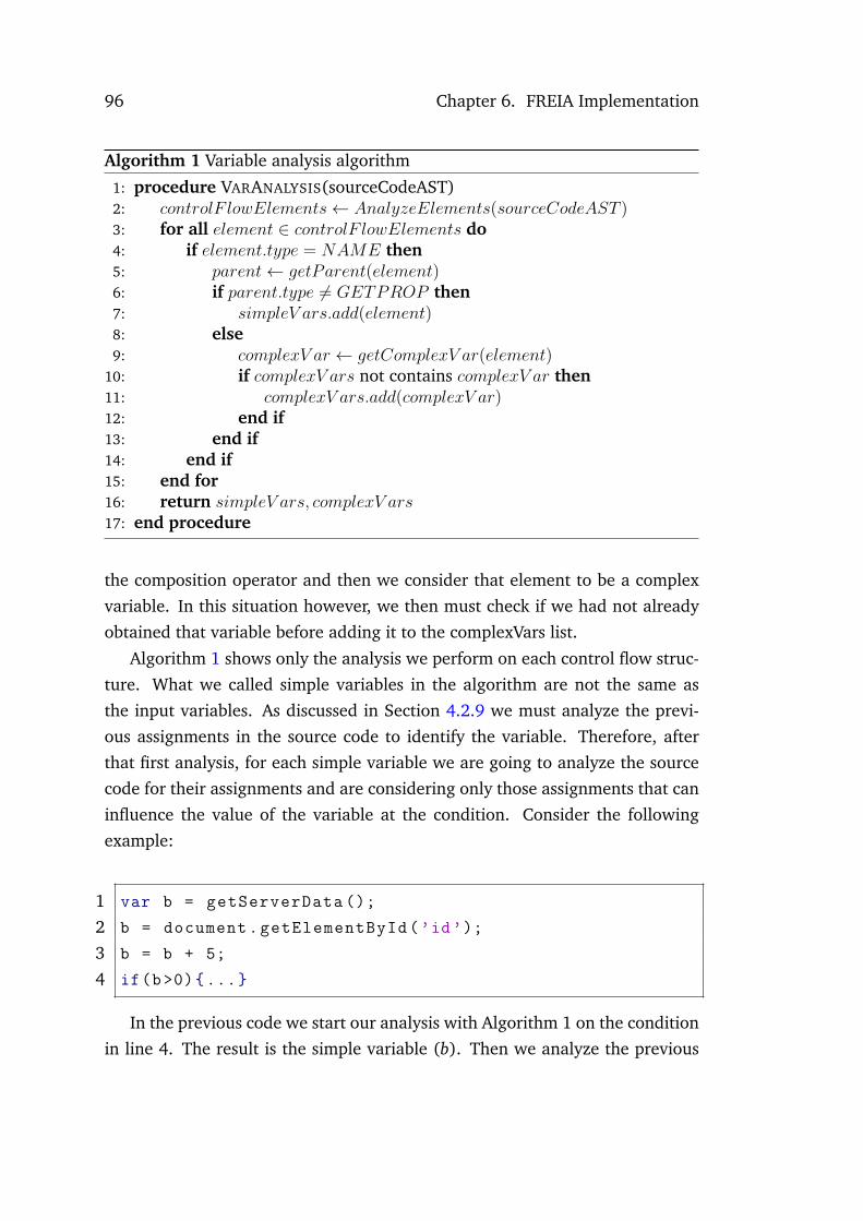
96 Chapter 6. FREIA Implementation
Algorithm 1 Variable analysis algorithm
1: procedure VARANALYSIS(sourceCodeAST)2: 𝑐𝑜𝑛𝑡𝑟𝑜𝑙𝐹 𝑙𝑜𝑤𝐸𝑙𝑒𝑚𝑒𝑛𝑡𝑠← 𝐴𝑛𝑎𝑙𝑦𝑧𝑒𝐸𝑙𝑒𝑚𝑒𝑛𝑡𝑠(𝑠𝑜𝑢𝑟𝑐𝑒𝐶𝑜𝑑𝑒𝐴𝑆𝑇 )3: for all 𝑒𝑙𝑒𝑚𝑒𝑛𝑡 ∈ 𝑐𝑜𝑛𝑡𝑟𝑜𝑙𝐹 𝑙𝑜𝑤𝐸𝑙𝑒𝑚𝑒𝑛𝑡𝑠 do4: if 𝑒𝑙𝑒𝑚𝑒𝑛𝑡.𝑡𝑦𝑝𝑒 = 𝑁𝐴𝑀𝐸 then5: 𝑝𝑎𝑟𝑒𝑛𝑡← 𝑔𝑒𝑡𝑃𝑎𝑟𝑒𝑛𝑡(𝑒𝑙𝑒𝑚𝑒𝑛𝑡)6: if 𝑝𝑎𝑟𝑒𝑛𝑡.𝑡𝑦𝑝𝑒 ̸= 𝐺𝐸𝑇𝑃𝑅𝑂𝑃 then7: 𝑠𝑖𝑚𝑝𝑙𝑒𝑉 𝑎𝑟𝑠.𝑎𝑑𝑑(𝑒𝑙𝑒𝑚𝑒𝑛𝑡)8: else9: 𝑐𝑜𝑚𝑝𝑙𝑒𝑥𝑉 𝑎𝑟 ← 𝑔𝑒𝑡𝐶𝑜𝑚𝑝𝑙𝑒𝑥𝑉 𝑎𝑟(𝑒𝑙𝑒𝑚𝑒𝑛𝑡)
10: if 𝑐𝑜𝑚𝑝𝑙𝑒𝑥𝑉 𝑎𝑟𝑠 not contains 𝑐𝑜𝑚𝑝𝑙𝑒𝑥𝑉 𝑎𝑟 then11: 𝑐𝑜𝑚𝑝𝑙𝑒𝑥𝑉 𝑎𝑟𝑠.𝑎𝑑𝑑(𝑐𝑜𝑚𝑝𝑙𝑒𝑥𝑉 𝑎𝑟)12: end if13: end if14: end if15: end for16: return 𝑠𝑖𝑚𝑝𝑙𝑒𝑉 𝑎𝑟𝑠, 𝑐𝑜𝑚𝑝𝑙𝑒𝑥𝑉 𝑎𝑟𝑠17: end procedure
the composition operator and then we consider that element to be a complex
variable. In this situation however, we then must check if we had not already
obtained that variable before adding it to the complexVars list.
Algorithm 1 shows only the analysis we perform on each control flow struc-
ture. What we called simple variables in the algorithm are not the same as
the input variables. As discussed in Section 4.2.9 we must analyze the previ-
ous assignments in the source code to identify the variable. Therefore, after
that first analysis, for each simple variable we are going to analyze the source
code for their assignments and are considering only those assignments that can
influence the value of the variable at the condition. Consider the following
example:
1 var b = getServerData ();
2 b = document.getElementById(’id’);
3 b = b + 5;
4 if(b>0){...}
In the previous code we start our analysis with Algorithm 1 on the condition
in line 4. The result is the simple variable (b). Then we analyze the previous

6.5. Data Processing 97
assignments. We start with line 3, here we see that the variable is the result of
a sum between that variable and a number. Therefore we have to also analyze
the previous assignment which is in line 2, where we see that the variable cor-
responds to getting an element on the page. After exploration of that element
we find we can interact with it, therefore we consider the variable an input
variable. Notice that since line 2 is a new variable assignment, and the variable
is not referred we do not analyze line 1.
6.5.3 Input Generator
After we extract the control flow structures and their variables, we must then
generate values for those variables, which is the task of the input generator
component. Currently our input generator is capable of solving standard re-
lational operators, such as: equal to, greater than, etc. The constraint solver
works than based on the type of the variables, being able to work with both
numbers and strings. Moreover, we currently have implemented the ability to
solve the JavaScript string length function, and JavaScript string concatena-
tions. In terms of numbers, if nothing is specified in the condition we generate
a random value between -100 and 100. For strings if no length is specified in
the condition we test random strings composed between 1 and 5 characters.
The input generator also creates the source code statement in case the test
implies an instrumentation. Here the only different is that if the variable is what
we classified as complex we have to remove the "var" from the declaration.
1 var b = 5;
2 c.attrib = 5;
3 if(b>0 && c.attrib >0){...}
For instance, in the previous source code, if we placed the var declaration
in the variable instrumentation in line 2, we would have a JavaScript error.
However, if we did not place the var declaration in the instrumentation, on line
1 we could also have an error if the variable was not declared previously.

98 Chapter 6. FREIA Implementation
6.6 Interface Model Generation
Our prototype is currently exporting the state machine using State Charts ex-
tensible Markup Language (SCXML) 7 a state machine notation based on XML
(Barnett et al., 2014).
In order to create the SCXML we have, for each state, to create a statenode, and then we retrieve all the outgoing edges from the state and create
the transition nodes. Afterwards, we add a additional tags and attributes to
represent the instrumentation and the inputs we send in each transition.
For example, suppose we have a Web page that has a single text box and a
single button with the following event handler:
1 b = document.getElementById(’id’);
2 if(b>0){ //go to page 2}
3 if(c>0) { //go to page 3}
In line 2 we can identify variable b as an element variable therefore we
would test it by adding values for passing and failing the condition with for
example -2 and 2. Variable c in line 3 however, we are not able to discern
where it comes from. Therefore, we have to instrument the source code to test
it. As an example, the real application uses random numbers, suppose that the
values being tested are also -2 and 2. The resulting state machine we would
visualize is depicted in Figure 6.12.
Our tool would then generate the SCXML code depicted in Figure 6.13. The
initial attribute in line 2 identifies where the state machine starts. Afterwards,
lines 5-10 correspond to filling the textbox with the -2 value. We identify the
inputs by their XPATH. Lines 11-16 correspond to filling the textbox with the
2 value, notice that we represent a transition to another state with the nextattribute on the transition node. Lines 17-20 correspond to the first instrumen-
tation test, where the value -2 is instrumented to the variable c and lines 20-24
are the instrumentation of the value 2. Notice we keep track of the conditions
of the variables being tested in both filling the inputs, and instrumentation sit-
uations.
Besides the SCXML model, we also generate a folder with the DOM files
7http://www.w3.org/TR/scxml/ (last accessed: February 1, 2014)

6.7. Profiler 99
Figure 6.12: State Machine for the SCXML example
associated to which state discovered. Moreover, we also create a screenshot of
the page for each state discovered. For example, for the state machine depicted
in Figure 6.12, the framework creates a folder with three XML files and three
images.
Figure 6.14 depicts an excerpt of the source code used to take a screenshot.
Lines 1-2 correspond to using the TakeScreenshot functionality of Selenium.
However, how the screenshot is taken depends on the Web browser being used.
For instance, in Firefox, the process creates a div around the application under
analysis and the screenshot is taken on that div. Obviously, such div creation
would interfere with our state comparison. Thus, lines 3-6 have to be used
to remove that div from the page. In contrast, in Chrome there are no new
elements added to the page. In Chrome the screenshots have the size of the
browser’s window. This makes that Chrome screenshots are different in terms
of size than Firefox screenshots.
6.7 Profiler
Since there are events whose event handlers Visual Event is not able to detect,
we decided to implement a profiler to analyze the JavaScript code that is being
executed when we trigger one of those events. The profiler requires the Web
browser to be Firefox. This happens because we use a combination of two

100 Chapter 6. FREIA Implementation
1 <?xml version="1.0" encoding="UTF -8"?>2 <scxml xmlns="http://www.w3.org /2005/07/ scxml" initial="1"3 version="1.0">4 <state id="1">5 <transition event="B1" eventXPATH="/html [1]/ body [1]/ input [1]"6 next="1">7 <send target="/html [1]/ body [1]/ input [2]">8 <content condition="b>0">-2</content >9 </send>
10 </transition >11 <transition event="B1" eventXPATH="/html [1]/ body [1]/ input [1]"12 next="2">13 <send target="/html [1]/ body [1]/ input [2]">14 <content condition="b>0">2</content >15 </send>16 </transition >17 <transition event="B1" eventXPATH="/html [1]/ body [1]/ input [1]"18 next="1">19 <instrumentation condition="c>0">c=-2</ instrumentation >20 </transition >21 <transition event="B1" eventXPATH="/html [1]/ body [1]/ input [1]"22 next="3">23 <instrumentation condition="c>0">c=2</ instrumentation >24 </transition >25 </state >26 <state id="2"></state >27 <state id="3"></state >
Figure 6.13: SCXML example source code
Firefox extensions during the process: Firebug and Console Export8. Console
Export is a Firebug extension, that allows to export the logs from Firebug’s
console panel. However, notice the Console Export extension we are using
is a version we modified. This happens because we needed to export to a
file the data retrieved by Firebug when we stopped profiling and this was not
supported.
We set both Firefox extensions with the preferences depicted in Figure 6.15.
In lines 4-5, Firebug and Console Export are set to enabled in all the pages.
Line 6 sets the panel to be enabled in Firebug to be the console panel. Lines
7-8 enable both scripts and consoles in Firebug and lines 10-11 set the name of
the file we are using to store the profiling information, this is initially defined
in our Config class (see Section 6.5.1).
8http://www.softwareishard.com/blog/consoleexport/ (last accessed: February 1,2014)

6.7. Profiler 101
1 File scrFile = (( TakesScreenshot)driver ).2 getScreenshotAs(OutputType.FILE);3 JavascriptExecutor js = (JavascriptExecutor) driver;4 js.executeScript("var fxSS ="5 +"document.getElementById(’fxdriver -screenshot -canvas ’);"6 +"if(fxSS!=null){"7 +"fxSS.parentNode.removeChild(fxSS );}");
Figure 6.14: Screenshot source code
1 FirefoxProfile profile = new FirefoxProfile ();2 //...3 String domain = "extensions.firebug.";4 profile.setPreference(domain+"allPagesActivation","on");5 profile.setPreference(domain+"consoleexport.active",true);6 profile.setPreference(domain+"defaultPanelName",7 "console");8 profile.setPreference(domain+"script.enableSites",true);9 profile.setPreference(domain+"console.enableSites",true);
10 profile.setPreference(domain+"consoleexport.logFilePath",11 currentDir.getCanonicalPath ());
Figure 6.15: Firefox extensions preferences
Afterwards, when we are triggering events, we use the Java code depicted
in Figure 6.16. We activate the profiling in line 2, then we trigger the element
in line 3 and afterwards we stop the profiling in line 4. With the preferences
defined previously, this creates an XML file with all the JavaScript functions that
were executed and their execution times. Afterwards, the XML file is analyzed
in order to sort the execution times, to see which was the function that was
called first.
Although this approach enable us to find which was the JavaScript source
code executed when an element was triggered, instrumenting the code with
our generated values can be troublesome. For instance, if the function we find
is an event delegation function such as an onload on the body tag, setting a new
name of that function and assign it to the triggered element on the page could
have unforeseeable results.

102 Chapter 6. FREIA Implementation
1 JavascriptExecutor js = (JavascriptExecutor) driver;2 js.executeScript("console.profile(’search ’)");3 eventElem.click ();4 js.executeScript("console.profileEnd ()");
Figure 6.16: Profiler event triggering source code
6.8 Summary
In this chapter we presented how we implemented FREIA. Each component im-
plementation is detailed and two new components, the interface model gener-
ation component and the profiler component, that correspond to new features
in the application are also described. The next chapter presents examples of
applying FREIA to reverse engineer Web applications.

Chapter 7
Case Studys
To better illustrate the Web Applications’ crawling and analysis process this
chapter explains how our tool performs in three distinct applications. The ap-
plications chosen were the following:
• Contacts Agenda - this application was based on an application previously
developed in Java (Silva et al., 2010). We then adapted the application
to Ajax. However, the application used in (Silva, 2010) only had the
JavaScript for enabling and disabling frames and a basic authentication
function, thus only working on the client side. The application used in
this analysis is fully functional with a database and all the JavaScript
functions, including server side calls, developed.
• Class Manager - this application, which preceded the development of our
framework, was originally developed to help teach Ajax technology and
was based on an example from Hadlock (2006).
• Neverending Playlist - this is a third party application. We do not have
access to its servers and therefore did not change its contents. We chose
this application as the example of third party analysis because of the dif-
ference in terms of number of states it has depending on the abstraction
levels chosen, thus emphasizing several features of our framework.
Therefore the three examples are based on who was the developer if the ap-
plications. The first example was an application developed by us with concerns
to highlight features of Reverse Engineering tools such as our framework. The
second was an application that was developed several years before our research

104 Chapter 7. Case Studys
to which we just added one or two features to make it a bit more complex. The
third was an application we found on the Web to which we did not perform any
changes.
In all examples we are going to make a comparison between our framework
results and the results obtained with the Crawljax (Mesbah et al., 2012) and
Artemis (Artzi et al., 2011) tools. We chose these tools for analysis from all the
ones presented in Chapter 2 for the following reasons:
• Access - Not all the applications presented were available.
• Communication - We were able to contact the developers of both tools
which provided significant aid in their usage and configuration.
• Targets - Both these tools also target Web applications.
• Output - Crawljax also generates state machines. Artemis generates test
traces and source code coverage. Therefore, we compare all the paths
possible in the state machines created by our framework with the paths
explored by Artemis.
The remainder of this chapter explains the three example applications anal-
ysis in detail.
7.1 Contacts Agenda
The Contacts Agenda is an example of a Rich Internet Application. The client
side uses Ajax to enhance the interaction with the user which does not sees any
page reloading in the browser since the server calls are made asynchronously.
The server side is implemented using PHP as the server side language and
MySQL as the database.
The Contacts Agenda application is composed by five frames: the Loginframe, the Mainform frame, the Find frame and the Edit frame and the Errorframe.
The application starts with the Login frame, which is used for the user’s
authentication. After successful authentication the application moves into the
Mainform frame, which displays an overview of the user’s contacts. Contacts
are listed either by their email or by their name. From here a user can perform

7.1. Contacts Agenda 105
several actions: he can search for contacts, which will open the Find frame or
he can add, edit or remove contacts. Adding and editing contacts will open the
Edit frame. If an error occurs while the user is using the application, the Errorframe appears stating the problem. Errors include not filling data required in
the fields, failed authentications and no results in searching for contacts.
The following is a description of the application’s several frames and the
result of the framework analysis on each step.
7.1.1 Login
Figure 7.1: Login Frame
When the user opens the Web Page, the first thing that appears is the Loginframe which is depicted in Figure 7.1.
The frame is composed by two input boxes, one for the username and the
other for the password, and by two buttons: Ok and Cancel. Lets assume this
initial state is called S1. The Cancel button only cleans whatever text was typed
in the textboxes, thus clicking it will maintain the application in the same state.
Therefore, an analysis at this point would retrieve an initial state machine as
depicted in Figure 7.2.
Clicking the Ok button leads to three different events: if there is no text
in the input boxes we go into an Error state declaring that "No text entered".
For differentiating purposes error states will be defined with an E, thus we will
call this one E1. If both inputs are filled an asynchronous server call, with the
authentication data, is sent.

106 Chapter 7. Case Studys
Figure 7.2: State Machine 1
The response from the server will distinguish between wrong authentication
data, which would trigger the application into another error state with the
following text: "Login failed! Verify user and password" which we will call
E2, and correct authentication would make the Mainform frame appear. This
information would get us a state machine as depicted in Figure 7.3.
Figure 7.3: State Machine 2
In order to better understand how FREIA works, we will further detail what
happens in the Ok button and how the other states are triggered and discov-
ered. The Ok button source code is depicted in Figure 7.4.
When analyzing this source code, the event analyzer component detects two
variables, "username" and "password", and both are classified as input variables.
Afterwards, the input generator analyzes both variables in the condition and
decides it has to generate for both a random String and the empty String.
However, in this particular case of authentications we could test a huge
amount of different values and never be able to get a correct authentication
pair. Thus, our framework has the feature of allowing the user to manually
define input values for chosen elements, we do this by having an external file
with the pairs of the element XPATH and the value we want to test. Therefore,

7.1. Contacts Agenda 107
1 function getMessageResponse (){2 var username = document.getElementById(’name’).value;3 var password = document.getElementById(’pass’).value;4 if(username !="" && password !=""){5 //do assynchronous server request6 }7 else {8 createCustomAlert("No text entered!")9 }
10 }
Figure 7.4: Login frame Ok button source code
considering the random value string to be ’a’ in both variables, and one correct
login authentication to be the pair <’john’, ’abc’> in the analysis of this button
the framework would generate the test cases depicted in Table 7.1.
Test Case Username Password Next State1 ” ” E12 ’a’ ” E13 ’john’ ” E14 ” ’a’ E15 ” ’abc’ E16 ’a’ ’a’ E27 ’a’ ’abc’ E28 ’john’ ’a’ E29 ’john’ ’abc’ S2
Table 7.1: Test cases for the Ok button
It is important to notice that our framework is not solving the logical con-
junction but instead testing all possible combinations of the variables. Since we
have three values in this case for two variables, we test the button 9 times to
cover all the combinations.
Moreover, since the difference between reaching state E2 and S2 is not being
defined in the function we are analyzing but in the server side call, without the
external values for the authentication we could have not discovered we could
reach S2. This shows a limitation of our approach, and in order to solve it
we would need to add server side code analysis to our framework. However,

108 Chapter 7. Case Studys
without the source code analysis we might miss finding both E2 and E1.
7.1.2 Mainform
The Mainform frame, the main application frame, is depicted in Figure 7.5. It
contains the list of contacts associated of the authenticated user. FREIA analysis
of the frame discovers it is composed by five buttons: Find, Add and Exit, which
are enabled by default, and Edit and Remove which are disabled. The disabled
buttons are enabled when a contact is selected on the list.
Figure 7.5: Mainform Frame
By default the frame appears with the email of the contacts. When our
framework triggers the Name radio-box the information on the display list
changes to show the names of the contacts, thus this will create a new state
which we will call S3. Clicking in Name when we are in S3 will return us back
to S2. Clicking the Find button will lead us to the Find frame (S4) and clicking
the Add button will make the application go to the Edit frame (S5). Moreover,
clicking the Exit button will get us back to the Login frame.
Since both S3 and S2 are the Mainform frame but with different contents,
they will have the same action transitions. Nevertheless, the framework trig-
gers the events in both S2 and S3. When we select a contact in the list, the
framework creates a new state S6 which corresponds at the Mainform frame

7.1. Contacts Agenda 109
Figure 7.6: Mainform State Machine
having the buttons edit and remove now enabled. Triggering the Edit button
in S6 will lead us to the Edit frame (S5) with the contact information filled.
The Remove button will remove the contact from the list, thus moving the ap-
plication to another Mainform frame. In summary, the analysis of this frame
by FREIA will produce a state machine similar to the one depicted in Figure
7.6. Although not present in Figure 7.6 for simplification, notice that S6 and
S7 will also have the same transitions as S2, namely the Exit, Find, Name and
Edit transitions.
As an implementation decision the Edit frame is exactly the same both in
case of adding new contacts or editing a contact, being the only difference that
editing a contact will open the frame with that contact data retrieved from the
database.
7.1.3 Find
The Find frame, depicted in Figure 7.7, enables users to search for contacts in
their agenda. FREIA analysis of the frame shows it is composed by a textbox,
used for users to input the search data, by two checkboxes, to refine the search

110 Chapter 7. Case Studys
in terms of match case or whole words, and by three buttons: Search, Canceland Show.
Figure 7.7: Find Frame
When the Cancel button is clicked the application goes back to the Mainformframe, thus no search is performed. The Show button has no logic associated
with, thus when it is triggered nothing happens in the application. The Searchbutton works as follows: if no text is present on the textbox it triggers an error
state "No text entered", which we will call E3. If there is text on the textbox
the application calls a function to search for the contact. The function called
depends on the checkboxes. Since there are two checkboxes we have four
different functions that can be called, to cover all the possible combinations.
The search functions can yield no results which would lead us no another error
state informing that there was "No contact found", which we will call E4. If the
search function finds a result the application goes back to the Mainform frame
with that result highlighted. Considering a result being selected enables both
the Edit and Remove buttons, instead of moving back to S2 the application goes
to another Mainform state (S4). A subset of the state machine with only the
states directly related with the find frame is depicted in Figure 7.8.
Since the search function is more complex than all the others in this applica-
tion, it is important to show how the framework handles each part of the source
code which is depicted in Figure 7.9. The first control flow statement is defined

7.1. Contacts Agenda 111
Figure 7.8: State Machine of the Find frame
in line 3, and the framework classifies the fi variable as an input variable, and
creates the test for triggering the button with or without a random string filled
in the findInput textbox. The empty string test is what enables us to reach state
E3.
Afterwards in lines 7,9,11 we have conditional structures that use both vari-
ables mc and ww. The way our framework handles these variables is quite
interesting. It analyzes the statements where they are declared, lines 4 and 5.
At this point, our prototype is not able to identify the checked attribute, and
classify the variables as inputs since we are only detecting textboxes as input
elements. Therefore, both variables are classified as complex variables, which
means we have to perform source code instrumentation for both. For instance,
a instrumentation performed is by adding the following code:
1 mc=document.getElementById(’matchCase ’). checked=true;
This is interesting because when analyzing the browser in runtime, after
we instrument that code, a tick appears in the checkbox. Thus, although not
able to understand checkboxes as input controls in the version used, the tool
correctly handles them through the instrumentation of the source code. Adding
checkboxes as input controls to the framework is simply a process of adding a
new form of input that instead of generating values we just have the selected or

112 Chapter 7. Case Studys
1 function search (){2 var fi = document.getElementById(’findInput ’).value;3 if(fi!=""){4 var mc=document.getElementById(’matchCase ’). checked;5 var ww=document.getElementById(’wholeWords ’). checked;6 var result = -1;7 if(!mc && !ww) {8 result = findContacts(findInput );}9 else if (mc && !ww) {
10 result = findContactsMC(findInput );}11 else if (!mc && ww) {12 result = findContactsWW(findInput );}13 else {14 result = findContactsWWMC(findInput );}15 if(result >=0){16 contactsList.options[result ]. selected=true;17 findExit ();}18 else {19 createCustomAlert("No contact found!");}20 }21 else {22 createCustomAlert("No text entered!")}23 }
Figure 7.9: Search function source code
not selected options. We decided not to include such a feature in the framework
so that we can analyze how the framework performs with unsupported widgets.
Another important analysis is performed in line 15. This conditional state-
ment is what defines if there was any result found in the server and selects
that result in the contacts list. Since the only previous declaration of the resultvariable is assigning it to a number, we consider the variable to be complex and
have therefore to instrument the variable for both cases. In case we instrument
the result variable to a negative number, we discover state E4. The positive
number however is where we first discovered the capability of our tool to dis-
cover problems in the source code. This happens because any random value we
instrumented that was outside of the bounds of the options list would trigger a
JavaScript error. For example, a run that instrumented the value 20 produces

7.1. Contacts Agenda 113
a JavaScript error of index out of bounds. If the value was inside the bounds,
the application behaved as supposed and we moved back to S2 with the found
contacted selected.
This particular situation made us realize that an hybrid approach, besides
enabling us to obtain more detailed models, also enables the detection of prob-
lems in the code during the crawling process. More specifically, problems due
to the conditional expressions not covering the full space of possible values for
the variables. Situations like that might happen when programmers assume
that values returned by calls to the application’s logic will conform to some
(possibly unspecified) condition. For example, assuming that querying some
entity by its key will always return a non null value, or assuming that the calcu-
lation of some measurement will always return a positive value. In those cases,
the (hidden – in the sense that they are not explicitly recorded) assumptions
that are being made about the return values mean that testing for null or for
negative values might be overlooked.
The presence of hidden assumptions creates two classes of problems, in both
cases related to the lack of an explicit formulation of those assumptions. On
the one hand, the assumptions, not having been documented and analyzed,
might simply be wrong; on the other hand, even if they are correct, the system
maintainability is negatively impacted. Since these assumptions are not doc-
umented, it becomes more likely that future changes to the application logic
might break them.
Thereafter we need to be able to detect these errors when they occur. There
can be several forms of detecting the errors. If we are analyzing legacy soft-
ware, and have previous versions of the models of the target application, we
can see if the model created is different from the one that was expected. Oth-
erwise, if the application is being analyzed for the first time, we need to detect
the JavaScript errors that occur after triggering the event. This is the reason
we implemented the Error detection feature described in Section 6.3.3.
Nevertheless, with such an analysis we are able do discern that the ap-
plication only moves to S6 if the conditional statement in line 15 is satisfied.
Moreover, we also have information that the application moves to E3 if the con-
ditional statement in line 3 fails, that is, the textbox has no value. Therefore,
we have a state machine with the same events leading to different states but
we have information about the source code control flow structures that were

114 Chapter 7. Case Studys
satisfied or not to reach those states, and the values we used in our analysis,
either in input fields or instrumented, to test those control flow structures. This
removes much of the ambiguity present in models generated by purely dynamic
analysis tools.
7.1.4 Edit
The Edit frame enables users to edit a contact in their agenda. The same frame
is also used for adding contacts. The only difference is that no data is filled in
the textboxes. The frame is depicted in Figure 7.10.
Figure 7.10: Edit Frame
The Edit frame is composed of five textboxes used for adding the contact
information. There was a feature for adding multiple emails using the buttons
Add, Edit and Remove, that we decided to disable, because adding, editing and
removing contacts are the only operations that will change the state of the ap-
plication, that is the information of the contacts that is present in the Mainformframe. Having another situation that is exactly the same seemed unnecessary
and would just be adding more complexity to the models, making their de-
scription more complex. The Edit frame also contains two buttons Cancel and
Ok.
When FREIA triggers the Cancel button the application returns to the previ-
ous state, that is, the Mainform frame. The Ok button first checks if all the fields

7.1. Contacts Agenda 115
were filled. In case there are empty fields, the application goes to an error state
notifying the user to "Fill in correctly all required fields", which we will call E5.
Otherwise, the application sends an asynchronous server call to add the data to
the database. We are using the email as the unique key for each contact, thus if
the email already exists in the database instead of adding a new entry we just
edit the existing one.
1 function okEdit (){2 // variables declaration3 if(fN!="" && lN!="" && tE!="" && nN!="" && eM!=""){4 // Server side call5 }6 else{7 createCustomAlert("Please fill all fields");8 }}
Figure 7.11: Edit frame Ok button event handler
An excerpt of the Javascript function being executed when the Ok button is
pressed is present in Figure 7.11. All five variables in the if condition are inter-
preted correctly as input variables by our framework, since they all correspond
to each of the five textboxes in the edit frame. As discussed previously we ana-
lyze every combination of the variables. Therefore, in this case we perform 32
tests. From those 32 tests only one corresponds to all the textboxes filled and
thus only one will go to a different state than the error state.
This example also serves the purpose of showing how this analysis can easily
deteriorate in terms of time consumption due to the increasingly high number
of tests we can have to perform. One possible solution could be to reduce the
test cases by just testing either all fields empty or all fields filled. Although, this
would work on this example, we might miss states on other applications.
In case all the textboxes are filled, we then create the new contact and add
it to the list. Since the list has now one more element our framework perceives
it as a different state, we called it S6. There can be situations, where the email
added is the same as one already existing in the contacts list, or in case we are
editing a contact, that the contacts list remains the same.
Thus clicking the Ok button can either lead us to S2 or S6 in case every

116 Chapter 7. Case Studys
textbox is filled and to E5 otherwise. Figure 7.12 depicts a subset of the state
machine generated by our framework at this point.
Figure 7.12: State Machine of the Edit frame
The creation of S6 has several important implications in the subsequent
analysis performed by our framework. For example, lets assume there are still
events to test in S5 in the state machine from Figure 7.12. As discussed in Sec-
tion 6.3.2 the Reach State component would reopen the browser, thus leading
us to S1, and then trigger Ok and then Add in order to get to S5. Clicking Okin S1 at this point however will lead us instead to S6 (because we now have
one more contact in the list), and at that point there are no known connections
between S6 and S5 since the Add button in S6 was not yet tested. Therefore,
we must mark the events in S5 as unreachable and move on with our analysis.
Afterwards, eventually the Add button is tested in S6 and at that point we
reset the events in S5 to be tested again. This leads to a problem because
since every time we reach a state from a new state we reset its events we now
have a non finite state machine since the framework will keep adding contacts
and thus we keep adding new states in the state machine. Our solution to this
problem was to also have a threshold for the number of times an event is tested.
Thus, even if we reset the events on S5, if the event was triggered more times
than the threshold, that event will not be triggered again unless for the need of
reaching a state.
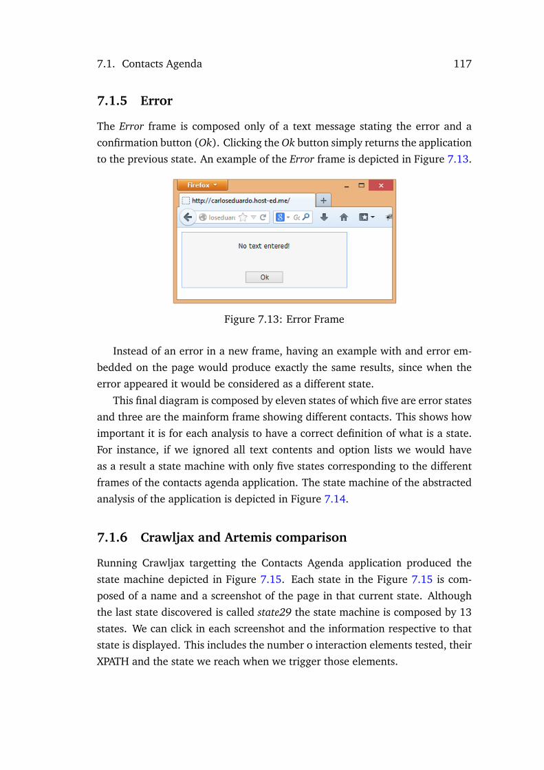
7.1. Contacts Agenda 117
7.1.5 Error
The Error frame is composed only of a text message stating the error and a
confirmation button (Ok). Clicking the Ok button simply returns the application
to the previous state. An example of the Error frame is depicted in Figure 7.13.
Figure 7.13: Error Frame
Instead of an error in a new frame, having an example with and error em-
bedded on the page would produce exactly the same results, since when the
error appeared it would be considered as a different state.
This final diagram is composed by eleven states of which five are error states
and three are the mainform frame showing different contacts. This shows how
important it is for each analysis to have a correct definition of what is a state.
For instance, if we ignored all text contents and option lists we would have
as a result a state machine with only five states corresponding to the different
frames of the contacts agenda application. The state machine of the abstracted
analysis of the application is depicted in Figure 7.14.
7.1.6 Crawljax and Artemis comparison
Running Crawljax targetting the Contacts Agenda application produced the
state machine depicted in Figure 7.15. Each state in the Figure 7.15 is com-
posed of a name and a screenshot of the page in that current state. Although
the last state discovered is called state29 the state machine is composed by 13
states. We can click in each screenshot and the information respective to that
state is displayed. This includes the number o interaction elements tested, their
XPATH and the state we reach when we trigger those elements.

118 Chapter 7. Case Studys
Figure 7.14: Contacts Agenda abstract state machine
In order to obtain this state machine, we had to add the correct authenti-
cation values to the Crawljax configuration. However, a immediate difference
from our tool is that if we add specific input values for fields, no other values
are tested on those fields. That means Crawljax misses the two error states
that can be reached from the Login frame. Also the Login frame information
showed that 16 elements were tested in the initial page, and only one triggered
a change which was the Ok button. This showed that Crawljax tried to trigger
all the buttons including those that were invisible since they belong to other
frames. A Crawljax run without the authentication information specified re-
turn two states, the Login frame and the Error frame. The error frame that is
found depends the configuration option to use random values. If we choose to
use random values, Crawljax never tests the empty cases so it only discovers the
"login failed" error. If we choose not to use random values, Crawljax discovers
only the "no text entered" error.
The MainForm frame analysis also presents several differences in compari-
son to our framework. The radio-buttons are not tested by Crawljax. Similar to
our framework, the elements on the list are selected, therefore Crawljax is able
to trigger both the Remove and the Edit buttons. Nevertheless, the edit button
transition does not lead to the add frame and the remove button is a transition
from a list with 2 elements to a list with 4 elements. Therefore, something

7.1. Contacts Agenda 119
Figure 7.15: Crawljax contacts agenda state machine
was wrong with the analysis and this state was incorrectly mistaken with some
other state. This problem was further analyzed in the Class Manager case study
in Section 7.2.3.
The Find frame analysis discovered events in all the buttons. The search
button led to the "no contact found" Error frame. Since the empty field was
not tested and a correct value was not entered the other two states were not
discovered. A strange thing happens with the analysis of the show button. This
is a button that was referred before as not containing any behavior whatsoever
associated with. Crawljax however detects a new state when triggering this
button.
A more thorough analysis of the state machine identified why this problem
happens. At some point in the crawl, Crawljax is able to add more contacts to
the contact list. When it tries to return to the Find frame (state2 in Crawljax
state machine) it in fact reaches a different state (with more contacts in the list
without noticing it. It is only when it tests the Show button that it analyzes the
state and considers that a new state was found (state 19). State 19 corresponds
to a state exactly the same as state2 the only difference being that now the
contact list (which is inf fact invisible) now has more elements. When Crawljax
returned to the Find it should have discovered that it now was not state 2

120 Chapter 7. Case Studys
but a different state since it was considering invisible elements. The same
situation was what we identified previously in the Mainform frame and happens
throughout the entire state machine.
Since we used the random values option which makes Crawljax fill all the
input fields, the Edit frame analysis found that triggering the Ok button would
generate a new state, which corresponds to the Mainform state with one more
contact. Therefore, it did not find the error state in the Edit frame, since the
fields were always all filled.
The Artemis tool has three different run modes. The default uses a feedback
directed approach and generates execution traces of the application. The man-
ual mode is used for manual testing and therefore will not be used for analysis.
The concolic mode performs a concolic analysis of form validated code and
generates a tree with the concolic results.
An analysis of the path traces Artemis generates shows a problem which
is that the traces generated are triggering elements that are not visible on the
page. Since there is no option to use predefined values in fields, the application
is never able to pass the login frame. Nevertheless, most iterations are using
these elements which are invisible on the page. This is very problematic since
for example a run with 100 iterations only contained three iterations where the
Ok button present in the login frame was triggered. Moreover, in none of those
three iterations the Ok button from the error frame that appears afterwards
was triggered. This means that if we ran all the 100 iterations we would only
have found 2 states and only one of both transitions between them.
An excerpt of the generated Artemis tree from its concolic mode is depicted
in Figure 7.16. In terms of the concolic analysis of this application Artemis
failed to discern both branches in the only condition it found on the source
code. That condition corresponds to a function, in the Mainform frame, that
checks if a contact was selected on the list and enables the edit and remove
buttons accordingly. One of the reasons the concolic solver failed might be that
the tool is not able to reach a state where the contact list is displayed since
it cannot solve the authentication. It is peculiar that all the other branches
present in the source code were not discovered and analyzed.

7.2. Class Manager 121
Figure 7.16: Artemis concolic analysis tree
7.2 Class Manager
Another example is the application of the framework to a classes management
application, supporting the registration of students, and their grades, in differ-
ent classes.
Like the previous example, all the possible actions in the application are per-
formed without reloading the Web page. However, in this case instead of using
the classic PHP and an SQL database, the entire application is build with only
HTML and JavaScript, and the requests are done to a database that contains
the students data. Therefore, except the database, all the application is on the
client side.
Its interface (see Figure 7.17) consists of a main area with the list of students
and grades (on a table). Above it sits a menu bar with the available actions (in
this case, removing the selected students, opening the add students panel, or

122 Chapter 7. Case Studys
Figure 7.17: Class Manager Application
opening the search panel), and, on the top left corner, a drop-down menu to
select the class to display. Moreover, there is a button called Last Class which
enables the user to quickly return to the last class used in the previous working
session.
The application starts with an empty table. At that point, the only actions
possible are to choose a class through the drop-down menu, or to go to the pre-
vious working class. The Search button is also enable by default, thus clicking
it will open the search panel, but no results are retrieved since there are no
students in the list. When a class is chosen, the students are listed in the table.
In order to remove students from the class, we need to select the correspond-
ing student checklist and then click on the Remove Selected button. Triggering
the Add or Search buttons options changes the UI by adding a new area with a
dialog for the user to enter the student data or the search terms.
Applying our tool on this application and considering the table’s content to
be irrelevant to our state definition, the model we would expect to get is the
state machine depicted in Figure 7.18. To remove the table information from
the analysis we remove all the td and tr tags from the state comparison.
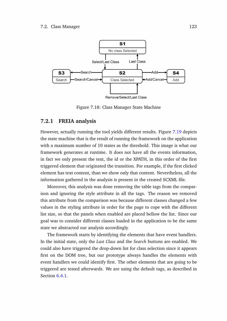
7.2. Class Manager 123
Figure 7.18: Class Manager State Machine
7.2.1 FREIA analysis
However, actually running the tool yields different results. Figure 7.19 depicts
the state machine that is the result of running the framework on the application
with a maximum number of 10 states as the threshold. This image is what our
framework generates at runtime. It does not have all the events information,
in fact we only present the text, the id or the XPATH, in this order of the first
triggered element that originated the transition. For example, if the first clicked
element has text content, than we show only that content. Nevertheless, all the
information gathered in the analysis is present in the created SCXML file.
Moreover, this analysis was done removing the table tags from the compar-
ison and ignoring the style attribute in all the tags. The reason we removed
this attribute from the comparison was because different classes changed a few
values in the styling attribute in order for the page to cope with the different
list size, so that the panels when enabled are placed bellow the list. Since our
goal was to consider different classes loaded in the application to be the same
state we abstracted our analysis accordingly.
The framework starts by identifying the elements that have event handlers.
In the initial state, only the Last Class and the Search buttons are enabled. We
could also have triggered the drop-down list for class selection since it appears
first on the DOM tree, but our prototype always handles the elements with
event handlers we could identify first. The other elements that are going to be
triggered are tested afterwards. We are using the default tags, as described in
Section 6.4.1.

124 Chapter 7. Case Studys
Figure 7.19: Class Manager State Machine
The problem is that the drop-down list event handler was added to the
application through a level 2 DOM event, and thus the Visual Event tool cannot
detect it. Nevertheless, this event handler is tested as described bellow, this
shows the flexibility of our approach that tries to work with the maximum
amount of information available, but still works with the information it can
find. The Last Class button has a bug in its event handler that will be further
explained in the end of this section. In this particular run the values tested
made that clicking it will always return to the same state.
After clicking Search we have a new state which corresponds to the empty
table with the search panel active. Obviously it does not make sense to have
this state in the application since searching in an empty list will never retrieve
results. From this state, clicking either the Search or the Cancel buttons removes
the search panel, thus making the application return to state 1.
In state 1, since all the elements with event handlers were already tested
the framework begins to handle the other possible clickable elements. In this
particular case, the only element is the drop-down list. The framework chooses
a random select option from the list, which will load the class data into the
table, creating state 3.
Since we are excluding the elements from the list from the comparison the
difference between state 3 and state 1 is that the Add button is now enabled,
and clicking it will generate state 4. State 4 corresponds to the application
with the add panel enabled. Since there are no control flow statements in the
Add button, when we click the add no element is added and thus we return to

7.2. Class Manager 125
state 3. In case there were control flow statements, either testing the values
in the fields or the result of adding the new student, the framework would
have explored those statements generating values for the fields or performing
instrumentation in the event handler.
The masterselector transition corresponds to the framework clicking on the
first checkbox in the table, this selects all the other checkboxes, but otherwise
the application remains the same. However, there is a difference, when ele-
ments are selected on the table the Remove Selected button becomes enabled
therefore this will generate state 5. State 6 will correspond to the same situa-
tion but without the add frame enabled.
When the framework triggers the Search button in state 3 the application
opens the search frame. Although the table now has elements since we are
ignoring them this state is the same as state 2. Triggering search in this state
with random values did not yield any results so we return to state 3.
State 7 shows a problem with the application, when we change class with
the add frame enabled, we move to a state where the Add button is enabled and
the add frame is also enabled, and in this situation triggering the Add button
will disable the add frame. State 9 corresponds to selecting an element in State
7, which will enable the Remove Selected button. Also related to the bug in state
7, we now have two different behaviors when we click the Add in state 9, it can
either go to state 5 or 6.
State 8 corresponds to the search panel enabled with an element selected
and thus the Remove Selected button also enabled. State 10 corresponds to the
same problem we found in state 7 but this time with the search frame. That is,
we have the search panel enabled and the Search button also enabled.
7.2.2 Problems discovered
The state machine in Figure 7.19 enabled us to identify several problems in the
application. The analysis describe therein was carried out by visual inspection
of the models. However, since the models are state machines, automated anal-
ysis is also possible given appropriate tool support. For example, expressing
the models in MAL interactors and using the IVY workbench (Campos and Har-
rison, 2009), or using graph analysis such as in (Thimbleby and Gow, 2008;
Thimbleby, 2013). Visual inspection, albeit labor intensive, has the advantage

126 Chapter 7. Case Studys
of not being as focused in concrete types of properties as automated analysis.
As discussed above, the problems found included having frames enabled
with the access buttons that enable those frames also enabled, which make the
application behave unexpectedly. Furthermore, state 2 with the empty table
with just the search panel should not exist.
Moreover, running FREIA with other levels of abstraction also enabled us to
discover other problems. For example, Figure 7.20 depicts the result of running
FREIA ignoring all the text and attributes, that is, using the ONLYTAGS option
described previously.
Figure 7.20: Class Manager State Machine 2
The main problems discovered in this run are related to State 6 which is
an empty table with the add panel enabled. This happened because when we
have the add panel enabled in state 4 we can change the class selected. In this
run the framework selected the 0 index in the list, this made the framework
discover state 6. From state 6, clicking add will return the application to state
1. Afterwards, we manually tested adding an element in state 6 to check if
we could add elements to no class, but the result was the empty table. It is

7.2. Class Manager 127
important to notice that since we are only testing a random element from the
list, in the previous run we had not discovered this state, because the 0 index
was not tested. This happens because since the handler was not detected we
are not performing the static analysis in its source code, which can cause the
framework to miss a few states.
Figure 7.21: Class Manager with both frames enabled
Other problem found was State 8 which corresponds to having both the addand the search panel enabled, also something that was not intended. This state
is depicted in Figure 7.21. When we trigger the Search button, both Searchand Add buttons become disabled. However, if a class is loaded using the drop-
down list both buttons become enabled, thus triggering the Add button at this
point will make both frames enabled at the same time.
Another problem with the application was related to the Last Class button.
Clicking this button without any classes loaded instead of always going to the
"Class Selected" state, might also leads us to the "No Class Selected" state. In or-
der to understand what happens, an excerpt of the source code of the JavaScript
function that is triggered when we click the Last Class button is presented on

128 Chapter 7. Case Studys
Figure 7.22.
1 oController.recoverLastClass = function () {2 var elementIndex = recoverPreviousClass ();3 if(elementIndex !=0) {4 var classid = element.options[elementIndex ]. value;5 oAjax.makeRequest (...);6 }7 else {8 oController.cleanClass ();9 ...
10 }11 ...12 }
Figure 7.22: Select last class source code excerpt
During the analysis of the source code, it is inferred that elementIndex is a
synthesized variable. Therefore, the code needs to be instrumented with values
to cover both the the if branch and the else branch. To cover the if branch the
framework instruments the variable with a non zero random value. To cover
the else branch the value 0 (zero) is used.
In the if branch two situations might occur, depending on the random values
our framework generates. If the value maps to an existing class (that is, a
value inside the range of the element.options array), everything should work
as expected. We could think of considering that the Ajax request to the server
(oAjax.makeRequest) might also have problems, if the value used is not valid on
the server side. However, we see this as an issue with the implementation of
the business logic layer, and assume that calls to the business logic will always
return something.
A more relevant situation happens when the generated value points to a
class that does not exist in the list (for instance, if we instrument the variable
to a negative value). This will make the application behave unexpectedly. In
this particular case, the user interface will remain in the same state, and we
would have caught a JavaScript error with our framework
In this case, the problem is that it is being assumed that the list of classes
on the drop-down menu always corresponds to the classes that exists in the

7.2. Class Manager 129
application logic. In a distributed environment such as is the case of Web ap-
plications, it is easy to imagine situations where this assumptions would be
broken. For example, because some other user is also accessing the system and
removes one of the classes. In this case it would be advisable to test that a valid
class is indeed returned by the application’s logic. Indeed, this also raises the
issue of whether using the index in the drop down menu as the identifier of
the last used class is a good approach. Using some sort of unique key would be
more advisable (even if it represents extra implementation work).
What the above illustrates is that, using our tool to instrument source code,
we are able to cause and detect misbehaviors on the application, which in this
case correspond to problems in defining the conditional clauses appropriately.
7.2.3 Crawljax and Artemis comparison
The result of running Crawljax on the Class Manager application is the state
machined depicted in Figure 7.23. Only the initial state and the state with
the search panel enabled were discovered. This happened because Crawljax
was unable to handle the dropdown menu with the list of available classes and
correctly load the classes. Although we can see in runtime Crawljax changing
the values in the select list, it does not trigger it, and no class is loaded at any
point. We tried to manually add the elements as inputs and to add the select
option as a clickable button in the configuration but the result was always the
same.
Figure 7.23: Crawljax Class Manager state machine

130 Chapter 7. Case Studys
Artemis analysis in terms of traces is much better than the analysis of the
contacts agenda application. While in the previous example, only two states
were discovered, in this case an analysis of 100 iterations shows that Artemis
is able to use the select option to change the class and is able to trigger the
checkboxes in students list. There are still many traces with problems related
to triggering elements that are not visible. Moreover, in this example we can
also see traces that try to trigger disabled buttons, such as the Add button in
the initial state.
Figure 7.24: Artemis Class Manager concolic analysis tree
In terms of the concolic analysis, a subset of the generated tree is depicted
in Figure 7.24. In this example Artemis was able to solve both branches of the
condition it analyzed. That condition was related to the event when a class
is chosen in the select list. All other control structures present in the code
were not analyzed. The reason this happens is because Artemis triggers on
change events in the several input fields in the application but those fields are
all hidden and thus produce no change in the application. The buttons which
have events are not analyzed by Artemis, and thus their control structures are
subsequently also not analyzed.

7.3. Neverending Playlist 131
7.3 Neverending Playlist
Neverending playlist1 is a Web site that enables users to keep listening to songs
for an infinite amount of time. The user can choose an artist or a genre, or
click the "I’m feeling lucky" button for a random choice, and then a new page
will appear playing usually a Youtube video with a song based on the previous
criteria. Figure 7.25 depicts the initial page of the application.
Figure 7.25: Neverending playlist
7.3.1 FREIA Analysis
Our framework’s analysis of the initial page identifies one element with source
code containing control structures. That element is the "I’m feeling lucky" button
1http://neverendingplaylist.com/ (last accessed: February 1, 2014)
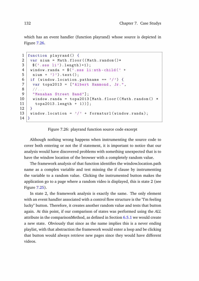
132 Chapter 7. Case Studys
which has an event handler (function playrand) whose source is depicted in
Figure 7.26.
1 function playrand () {2 var nium = Math.floor((Math.random ()*3 $(’.sss li’). length )+1);4 window.randa = $(’.sss li:nth -child(’ +5 nium + ’)’).text ();6 if (window.location.pathname == ’/’) {7 var topa2013 = ["Albert Hammond , Jr.",8 //...9 "Menahan Street Band"];
10 window.randa = topa2013[Math.floor((Math.random () *11 topa2013.length + 1))];12 }13 window.location = ’/’ + formaturl(window.randa );14 }
Figure 7.26: playrand function source code excerpt
Although nothing wrong happens when instrumenting the source code to
cover both entering or not the if statement, it is important to notice that our
analysis would have discovered problems with something unexpected that is to
have the window location of the browser with a completely random value.
The framework analysis of that function identifies the window.location.path
name as a complex variable and test missing the if clause by instrumenting
the variable to a random value. Clicking the instrumented button makes the
application go to a page where a random video is displayed, this is state 2 (see
Figure 7.25).
In state 2, the framework analysis is exactly the same. The only element
with an event handler associated with a control flow structure is the "I’m feeling
lucky" button. Therefore, it creates another random value and tests that button
again. At this point, if our comparison of states was performed using the ALLattribute in the comparisonMethod, as defined in Section 6.5.1 we would create
a new state. Obviously that since as the name implies this is a never ending
playlist, with that abstraction the framework would enter a loop and be clicking
that button would always retrieve new pages since they would have different
videos.

7.3. Neverending Playlist 133
This situation shows the importance of being able to increase the abstrac-
tion of our analysis according to the target applications. Specifically, this anal-
ysis was made using the ONLYTAGS attribute, which removes both different
attributes and the element contents from the comparison. Thus, clicking the
"I’m feeling lucky" button in state 2 will be a transition to the same state. State
2 will be different from state 1 since it does not have the video related tags.
Afterwards, the framework keeps testing all the other elements in the page.
Here we consider elements by their XPATH because the same XPATH elements
can have different contents. For example, bellow each video there is a list of
the next 35 songs that are next on the list, and each element XPATH changes
the contents as we move forward on the playlist.
Figure 7.27: Are you human page
When testing the different elements there is a chance we might end up in
a page to discern if the application is being browsed by a human. These pages
are usually used to prevent bots or automated programs to gather information
from websites. Obviously these will also hinder the analysis of crawlers such as
our framework. These is normally done by solving some sort of programs that
generate and ascertain tests humans can solve but computer programs cannot,
called CAPTCHAs (Ahn et al., 2003). Note however that this happens only
when we are analyzing third party applications. If the framework is being used
in support of development, this sort of situations should not be a problem. Nev-
ertheless, in this particular case the page is just a page with a link, as depicted
in Figure 7.27, this corresponds to state 3 in the state machine. Therefore, the
framework just clicks the only link in the page and we return to a page with a

134 Chapter 7. Case Studys
song playing.
Another situation that happen sometimes is when triggering the event the
instrumented "I’m feeling lucky" button the application opens a page warning
"Invalid Artist Name", this was named state 4. All the triggered elements in this
state returned to the same page except the "or go back home" button which
return the application to state 1. The transition between state 2 and state 4 is
probably a bug in the target application, since in that case clicking a artist ele-
ment led to the "Invalid Artist Name". One possible reason is that that specific
artist was at some point in the database an was later removed.
Figure 7.28: Neverending playlist state machine
State 5 and state 6 are states similar to state 2, that is, they have the page
and a video playing. The difference is that in state 5 there is no Facebook frame
active. Indeed, when we trigger a random artist, or one of the suggestions in the
page, sometimes the resulting page will have a Facebook frame for commenting
the respective song while in other cases it will have no such frame.
State 6 exactly the same as state 2 except is has a script tag in the header.
Although in this run the framework was only able to reach state 6 from a single
element, since we have several outgoing edges from state 6 it means we were
able to go back and test state 6. Moreover, analyzing the generated SCXML
showed that triggering that element could also move the application to state 5.
Therefore, we made an analysis in the log which showed that every time the
framework tried to reach state 6 it was successful, despite sometimes ending in

7.3. Neverending Playlist 135
state 3 and need to redo the search for state 6. This discovery of state 6 as a
different state begs the question if we should remove the head tag and all its
contents from the states comparison, since it just contains meta data about the
page and does not affect the interface elements.
7.3.2 Crawljax and Artemis comparison
Crawljax analysis of the Neverending Playlist application generated the state
machine depicted in Figure 7.29. We ran the analysis without limiting the
number of states or clicks. Nevertheless, the analysis stopped after discover-
ing 9 states. All the states discovered except state 7 correspond to the initial
page. State 7 is page with a video loaded. Since all the other states seem equal
through visual analysis, we manually compared the extracted DOMs and con-
cluded that these states are different because there are some differences in the
attributes of the twitter and facebook widgets.
Figure 7.29: Crawljax Neverending playlist state machine
A comparison between this state machine and the state machine created by
FREIA shows that Crawljax analysis just discovered the equivalent to state 1
and state 2 in Figure 7.28 state machine.

136 Chapter 7. Case Studys
Artemis analysis in terms of the path traces has some improvements com-
parison to the analysis performed in the previous examples. For once, now
events different from clicks (mousedown events) and opening pages appear in
the traces. For instance, mouseup events, keydown or keyup events with a ran-
dom value are now being tested in the application. Although most of them do
not change the application, the fact that input is now being filled in the forms
makes the analysis better.
Another difference is that while in the previous examples in 100 iterations
the maximum number of actions performed was 4 in a single iteration, in this
example we have some traces with 14-15 actions.
The time of the analysis in this example also drastically increased. This
happens because Artemis performs a full analysis of the source code and this
example application uses jQuery while the others examples did not use any
JavaScript library, therefore the amount of code this tool has to analyze is sig-
nificantly different between these examples.
Figure 7.30: Artemis Neverending Playlist concolic analysis tree
Artemis concolic analysis of this application did not found any branch to
test. Therefore, Figure 7.30 just presents a subset of the concolic tree generated
bottom.

7.4. Summary 137
7.4 Summary
In this chapter we presented FREIA analysis over three different Web applica-
tions. Moreover, we compared our results with analysis from other two tools,
Crawljax and Artemis. This comparison showed that our analysis has several
differences in comparison with the other tools.
In comparison with Crawljax testing only visible elements and the ability to
control the abstraction of our analysis makes our results more accurate. More-
over, when we analyze source code and generate input values based on that
analysis and when we instrument the source code our analysis discovers some
states Crawjax is not able to discover, it also enable us to add information to
the transitions and solve ambiguity problems in the models.
In comparison with Artemis, in terms of the path traces, we are not currently
generating path traces, although we have a tool that generates execution traces
from SCXML for Web Applications (Rodrigues, 2015), its integration however
is still work in progress. This will be further discussed in the future work (see
Section 8.3). Nevertheless, if we generated path traces from our state machine,
the traces would be more accurate, in terms that all actions would produce ac-
tual changes in the Application state. In contrast to Artemis path traces which
contained a great number of traces triggering either invisible or disabled ele-
ments.
In terms of the concolic testing not only have we analyzed more branches in
all the examples, Artemis concolic testing failed to solve a simple branch in the
Contacts Agenda application. Moreover, we take almost the same time in the
analysis of each page in all the examples, being the only difference a minimal
increase when we have to instrument source because we have to wait for the
code to be injected. On the contrary, Artemis execution time changed signif-
icantly between the last example and the other two because the last example
used the jQuery library.

138 Chapter 7. Case Studys

Chapter 8
Conclusions and Future Work
This thesis presented an approach to the reverse engineering of Internet appli-
cations. This document concludes with the answers to the research questions
defined in Section 1.5. Afterwards the main contributions and a discussion of
the work developed are presented. We conclude with indications for future
work.
8.1 Answers to the Research Questions
In the initial chapters of this thesis, the main problems with existing approaches
to the reverse engineering of Web applications were identified. This led to the
definition of this dissertation’s thesis as:
A hybrid approach to the reverse engineering of Web applications enable us toobtain better models than existing approaches.
This thesis raises three questions:
• Question 1: What types of models are better suited for abstracting theGraphical User Interface of Web applications? This dissertation has com-
pared a number of declarative GUI implementation languages with a
declarative modelling language. Given that the implementation technol-
ogy has moved towards declarative markup languages, we were inter-
ested in analyzing the viability of using the interfaces expressed in those
languages as models of the UIs. The results showed that not all aspects
of a user interface can be handled declaratively. Specifically, in terms of
behavior, these languages supported very limited features. This question
140 Chapter 8. Conclusions and Future Work
was addressed in Chapter 3. In summary, the answer to the question is
that although existing declarative languages are constantly being updated
with new features and are a viable option to describe the UI structure,
they are still not mature enough to express the behavior of the UI, which
has to be done using state machines or petri nets.
• Question 2: How to balance the usage of both dynamic and static analysisin the same approach? This dissertation presented an approach for the re-
verse engineering of Web applications based on using dynamic analysis to
explore an application, but also static analysis to guide that exploration.
Our approach showed it is feasible to statically analyze only a subset of
the source code (that is, the code in the event handler of the event being
triggered) and still obtain enough relevant information to guide the anal-
ysis. Moreover, the depth of the analysis can be customized in terms of
number of function calls to analyze. This question was addressed when
we presented our approach to a new framework in Chapter 4.
• Question 3: How much of the control logic of the User Interface (UI) canbe obtained from the analysis of event listeners in Web applications? This
dissertation has presented an analysis of the most popular 1000 Web sites
in terms of tags and the source code used. This provided an overview on
the type of logic that was being used. Around 65% of sites used some sort
of control flow structure, being that the mean was 80 statements per site.
This question was discussed in Chapter 5.
Given these answers, it can be concluded that indeed an hybrid approach to
the reverse engineering of Web applications enabled us to obtain better models
than existing approaches. This was illustrated in Chapter 7.
8.2 Summary of Contributions
The major contribution of this work was presenting an hybrid approach for
the reverse engineering of Web applications and the development of FREIA, a
framework that validates that approach. The framework explores a Web appli-
cation and extracts information about the UI layer. This includes the different
8.3. Future work 141
states an application can have from the users’ point of view, according to sev-
eral different types of abstractions and what elements were triggered to reach
those states. Furthermore, it is able to discern why the same elements can
lead to different states, thus creating state machines with information about
the conditions that control the behavior of the user interface.
FREIA was built following two major guidelines. On one hand, that it is
an incremental work, that is, that we should be able to keep adding more tech-
niques and more features to its analysis. For instance, two major aspects are the
ability to keep adding new ways of detecting events and input elements, and the
feature of adding widgets with different behavior, for instance, select menus as
depicted in the example in Section 7.2 are processed differently than buttons.
On the other hand that it is able to retrieve information on as much Web appli-
cations as possible. That is, if certain elements are missing, or if a page state
suddenly changes, or if we are not able to detect events, the framework will
use the other components that are working and still extract information.
Additional contributions include:
• a review of the state of the art in Reverse Engineering GUIs.
• a comparative analysis of several UI modelling languages.
• a study characterizing the control logic present in the event handlers of
the most popular Web sites.
This work originated the following scientific publications: (Silva and Cam-
pos, 2012), (Silva and Campos, 2013), and (Silva and Campos, 2014).
8.3 Future work
Throughout this dissertation a number of research problems were discovered.
This section presents some guidelines for future work.
Concerning the research about User Interface models described in Chap-
ter 3 future work includes implementing the idea of embedding a modelling
language in a implementation language, in order to increase the level of ab-
straction of the models.

142 Chapter 8. Conclusions and Future Work
Regarding the study performed on characterizing the control logic of the
Web applications discussed in Chapter 5, there were a few shortcomings in
our analysis that could be improved such as extending the element variables
identification to other frameworks or techniques, this could mean an analysis
of the entire JavaScript files similar to the one we are doing to identify event
delegation approaches. Furthermore, trying to find correlations between the
several criteria could also yield interesting results.
FREIA’s future work follows two major directions. One is to keep adding
new features to FREIA, and to generate new types of analysis. The other is
to focus on integrating FREIA with other tools to make a better use of the
information gathered.
New features for FREIA are for instance to add a second mode of operation
to the cases where we have access to the target application source code. This
would enable us to make use of the profiling component to detect the code
being executed and then be able to safely change the correct control flow struc-
tures without the need of adding new functions with the instrumented code.
Other feature is to deploy the tool, either to a Website, or as an Eclipse or Fire-
fox plugin, so that it could easily be used by other people. This would enable
the approach to be validated externally.
In terms of FREIA’s integration with other tools, since it is currently gen-
erating state machines in SCXML as well as a DOM representation for each
state and its corresponding screenshot, is feasible to use other analysis tools to
reason about the application. For example, Rodrigues (2015) presents a tool
that automatically generates test cases from models. In this case, SCXML is
also being used to represent the state machines. We can easily translate our
models to those models, and thus support the generation of test cases directly
from the implementation of the user interface. This will be useful, for example,
to support regression tests when systems are updated. Another option would
be to integrate FREIA with formal verification tools, such as IVY (Campos and
Harrison, 2009). In this case it would become possible to support the for-
mal verification of the user interface, while freeing developers from the need to
write the formal models, thus lowering the adoption barrier of such techniques.

Bibliography
Louis Von Ahn, Manuel Blum, Nicholas J. Hopper, and John Langford.
CAPTCHA: Using hard AI problems for security. In Proceedings of the 22ndInternational Conference on Theory and Applications of Cryptographic Tech-niques, EUROCRYPT’03, pages 294–311, Warsaw, Poland, 2003. Springer-
Verlag.
Jeremy Allaire. Macromedia Flash MX - A next-generation rich client. Macro-media white paper, 2002.
Domenico Amalfitano, Anna Rita Fasolino, Armando Polcaro, and Porfirio Tra-
montana. The DynaRIA tool for the comprehension of Ajax Web applications
by dynamic analysis. Innovations in Systems and Software Engineering, 10(1):
41–57, April 2014.
Shay Artzi, Julian Dolby, Simon Holm Jensen, Anders Moller, and Frank Tip.
A Framework for Automated Testing of Javascript Web Applications. In Pro-ceedings of the 33rd International Conference on Software Engineering, ICSE
’11, pages 571–580. IBM Research, Yorktown Heights, NY, USA, ACM, 2011.
Jim Barnett, Rahul Akolkar, R. J. Auburn, Michael Bodell, Daniel C. Burnett,
Jerry Carter, Scott McGlashan, Torbjörn Lager, Mark Helbing, and Rafah
Hosn. State chart XML (SCXML): State machine notation for control abstrac-tion. W3C working draft, 2014.
Mike Barnett, K Rustan M Leino, and Wolfram Schulte. The Spec# Program-
ming System : An Overview. In Proceedings of the 2004 International Con-ference on Construction and Analysis of Safe, Secure, and Interoperable SmartDevices, CASSIS’04, pages 49–69, Marseille, France, 2004. Springer-Verlag.

144 Bibliography
Youri Vanden Berghe. Etude et implémentation d’un générateur des interfaces
vectorielles à partir d’un langage de description d’interfaces utilisateur. Mas-
ter’s Thesis, 2004.
Tim Berners-Lee. WorldWideWeb, the first Web client. 1990.
D. L. Bird and C.U. Munoz. Automatic Generation of Random Self-checking
Test Cases. IBM Systems Journal, 22(3):229–245, 1983.
Nikolaj Bjø rner, Nikolai Tillmann, and Andrei Voronkov. Path Feasibility Analy-
sis for String-Manipulating Programs. In Proceedings of the 15th InternationalConference on Tools and Algorithms for the Construction and Analysis of Sys-tems, TACAS ’09, pages 307–321, York, UK, 2009. Springer-Verlag.
Grady Booch, James Rumbaugh, and Ivar Jacobson. The Unified Modeling Lan-guage User Guide, volume 3 of The Addison-Wesley Object Technology series.Addison-Wesley, 1999.
Laurent Bouillon, Quentin Limbourg, Jean Vanderdonckt, and Benjamin Mir-
chotte. Reverse engineering of Web pages based on derivations and trans-
formations. In In Proceedings of the third Latin American Web Congress, LA-
Web’05, 2005.
Gaëlle Calvary, Joëlle Coutaz, David Thevenin, Quentin Limbourg, Laurent
Bouillon, and Jean Vanderdonckt. A Unifying Reference Framework for
Multi-target User Interfaces. Interacting with Computers, 15(3):289 – 308,
2003.
José C Campos and Sandrine A Mendes. FlexiXML - A portable user interface
rendering engine for UsiXML. In User Interface Extensible Markup Language,
UsiXML’2011, pages 158–168. Thales Research and Technology, 2011.
José Creissac Campos and Michael D. Harrison. Interaction Engineering Using
the IVY Tool. In Proceedings of the 1st ACM SIGCHI Symposium on EngineeringInteractive Computing Systems, EICS ’09, pages 35–44. ACM, 2009.
José Creissac Campos, João Saraiva, Carlos Silva, and João Carlos Silva.
GUIsurfer : A Reverse Engineering Framework for User Interface Software.
Reverse Engineering - Recent Advances and Applications, pages 31–54, 2012.

Bibliography 145
Gerardo Canfora and Massimiliano Di Penta. New Frontiers of Reverse Engi-
neering. In 2007 Future of Software Engineering, FOSE ’07, pages 326–341,
Washington, DC, USA, 2007. IEEE Computer Society.
J. Chen and S. Subramaniam. A GUI environment to manipulate FSMs tor
testing GUI-based applications in Java. In In Proceedings of the 34th AnnualHawaii International Conference on System Sciences, page 10 pp, Washington,
DC, USA, 2001. IEEE Comput. Soc.
Elliot J. Chikofsky and James H. Cross. Reverse engineering and design recov-
ery: A taxonomy. IEEE software, 1990.
T.S. Chow. Testing Software Design Modeled by Finite-State Machines. IEEETransactions on Software Engineering, 4(3):178–187, 1978.
Paulo Pinheiro Da Silva and Norman W. Paton. User Interface Modeling in
UMLi. IEEE Software, 20(4):62–69, 2003.
Valentin Dallmeier, Martin Burger, Tobias Orth, and Andreas Zeller. WebMate
: A Tool for Testing Web 2.0 Applications. In Proceedings of the Workshop onJavaScript Tools, JSTools ’12, pages 11–15, 2012.
Vincent Denis. Un pas vers le poste de travail unique : QTKiXML, un interpré-
teur d’interface utilisateur à partir de sa description. Master’s Thesis, 2005.
ECMA. ECMA-262 ECMAScript Language Specification. JavaScript Specifica-tion, 16:1–252, 2009.
Eldad Eilam. Reversing: secrets of reverse engineering. Wiley Publising, 2005.
Jesse James Garrett. Ajax: A new approach to web applications. pages 1–5,
2005.
Andy Gimblett and Harold Thimbleby. User Interface Model Discovery : To-
wards a Generic Approach. In Proceedings of the 2nd ACM SIGCHI symposiumon Engineering interactive computing systems, EICS ’10, pages 145–154. ACM,
2010.
Patrice Godefroid, Nils Klarlund, and Koushik Sen. DART: directed automated
random testing. ACM Sigplan Notices, 40(6):213–223, 2005.

146 Bibliography
Yann Goffette and Henri Louvigny. Development of multimodal user interfaces
by interpretation and by compiled components: a comparative analysis be-
tween InterpiXML and OpenInterface. Master’s Thesis, 2007.
James Gosling, Bill Joy, Guy Steele, and Gilad Bracha. The Java Language Spec-ification. 2005.
André M P Grilo, Ana C R Paiva, and João Pascoal Faria. Reverse Engineering
of GUI Models for Testing. In Proceedings of the 5ª Conferencia Ibérica deSistemas y Tecnologías de la Información, CISTI ’10. IEEE, 2010.
Josefina Guerrero-Garcia, Juan Manuel Gonzalez-Calleros, Jean Vanderdonckt,
and Jaime Munoz-Arteaga. A Theoretical Survey of User Interface Descrip-
tion Languages: Preliminary Results. In Proceedings of 4th Latin AmericanConference on Human-Computer Interaction, CLIHC’2009, pages 36–43. IEEE,
November 2009.
Arjun Guha, Shriram Krishnamurthi, and Trevor Jim. Using static analysis for
Ajax intrusion detection. In ACM, editor, Proceedings of the 18th Internationalconference on World Wide Web, WWW ’09, pages 561–570, New York, New
York, USA, 2009. ACM Press.
Kris Hadlock. Ajax for Web Application Developers. Sams Publishing, 2006.
Ahmed E. Hassan and Richard C. Holt. Architecture recovery of Web applica-
tions. In Proceedings of the 24th International Conference on Software Engi-neering., ICSE ’02, pages 349–359. ACM, 2002.
James Helms, Robbie Schaefer, Kris Luyten, Jo Vermeulen, Marc Abrams,
Adrien Coyette, and Jean Vanderdonckt. Human-Centered Engineering Of
Interactive Systems With The User Interface Markup Language. In A Sef-
fah, J Vanderdonckt, and M Desmarais, editors, Human-Centered SoftwareEngineering, Human-Computer Interaction Series, pages 139–171. Springer
London, 2009.
Jesper G. Henriksen, Madhavan Mukund, K. Narayan Kumar, and P. S. Thia-
garajan. On Message Sequence Graphs and Finitely Generated Regular MSC
Languages. In Proceedings of the 27th International Colloquium on Automata

Bibliography 147
Languages and Programming, ICALP ’00, pages 675–686, London, UK, 2000.
Springer-Verlag.
Pieter Hooimeijer and Westley Weimer. A decision procedure for subset con-
straints over regular languages. SIGPLAN Not., 44(6):188–198, 2009.
Ivar Jacobson, Magnus Christerson, Patrik Jonsson, and Gunnar Overgaard.
Object-Oriented Software Engineering: A Use Case Driven Approach. Addison-
Wesley, 1992.
Jakob Jenkov. jQuery Compressed. Jenkov Aps, 2013.
Narendra Jussien, Guillaume Rochart, Xavier Lorca, Open Source, and Java
Constraint. Choco : An Open Source Java Constraint Programming Library.
In Open-Source Software for Integer and Contraint Programming, OSSICP’08,
pages 1–10, 2008.
Brian W Kernighan and Dennis M Ritchie. The C programming language, vol-
ume 78. 1988.
James C. King. Symbolic Execution and Program Testing. Communications ofthe ACM, 19(7):385–394, 1976.
Peng Li and Eric Wohlstadter. View-based maintenance of Graphical User In-
terfaces. In Proceedings of the 7th international conference on Aspect-orientedsoftware development, AOSD ’08, pages 156–167, New York, New York, USA,
2008. ACM Press.
Quentin Limbourg and Jean Vanderdonckt. Addressing the Mapping Problem
in User Interface Design with UsiXML. In Proceedings of the 3rd annual confer-ence on Task models and diagrams, TAMODIA ’04, pages 155–163, New York,
New York, USA, 2004. ACM Press.
Quentin Limbourg, Jean V, Benjamin Michotte, Laurent Bouillon, and Víctor
López-Jaquero. UsiXML: A Language Supporting Multi-Path Development of
User Interfaces. In Proceedings of the 2004 International Conference on Engi-neering Human Computer Interaction and Interactive Systems, EHCI-DSVIS’04,
pages 200–220. Springer-Verlag, 2004.

148 Bibliography
Josip Maras, Jan Carlson, and Ivica Crnkovi. Extracting client-side web appli-
cation code. In Proceedings of the 21st international conference on World WideWeb, WWW ’12, page 819, New York, New York, USA, 2012. ACM Press.
Josip Maras, Maja Štula, and Jan Carlson. Generating feature usage scenarios
in client-side web applications. In Florian Daniel, Peter Dolog, and Qing Li,
editors, Web Engineering, volume 7977 of Lecture Notes in Computer Science,
pages 186–200. Springer Berlin Heidelberg, 2013.
Atif Memon, Isham Banerjee, and Adithya Nagarajan. GUI ripping: reverse
engineering of graphical user interfaces for testing. In Proceedings of the 10thWorking Conference on Reverse Engineering, 2003, WCRE ’03, pages 260–269,
Washington, DC, USA, 2003. IEEE.
Sandrine Alves Mendes. FlexiXML - Um animador de modelos de interfaces
com o utilizador. Master’s Thesis, 2009.
Ali Mesbah, Engin Bozdag, and Arie van Deursen. Crawling AJAX by Inferring
User Interface State Changes. In Proceedings of the 2008 Eighth InternationalConference on Web Engineering, ICWE ’08, pages 122–134. IEEE Computer
Society, 2008.
Ali Mesbah, Arie van Deursen, and Stefan Lenselink. Crawling Ajax-Based Web
Applications through Dynamic Analysis of User Interface State Changes. ACMTransactions on the Web, 6(1):1–30, March 2012.
Inês Coimbra Morgado, Ana C. R. Paiva, and João Pascoal Faria. Dynamic
Reverse Engineering of Graphical User Interfaces. International Journal OnAdvances in Software, 5(3):224–236, 2012a.
Ines Coimbra Morgado, Ana C. R. Paiva, Joao Pascoal Faria, and Rui Camacho.
GUI reverse engineering with machine learning. In 2012 First InternationalWorkshop on Realizing AI Synergies in Software Engineering (RAISE), pages
27–31. IEEE, June 2012b.
David Navarre, Philippe Palanque, Jean-Francois Ladry, and Eric Barboni. ICOs:
A model-based user interface description technique dedicated to interactive
systems addressing usability, reliability and scalability. ACM Transactions onComputer-Human Interaction, 16(4):1–56, November 2009.

Bibliography 149
Nicholas Nethercote. Dynamic Binary Analysis and Instrumentation or BuildingTools is Easy. PhD thesis, 2004.
Nuno Jardim Nunes and João Falcãao e Cunha. Wisdom – A UML based ar-
chitecture for interactive systems. In Proceedings of the 7th international con-ference on Design, specification, and verification of interactive systems, pages
1–14, 2001.
Nuno Jardim Nunes and João Falcão. Towards Flexible Automatic Generation
of User-Interfaces via UML and XMI. In 5th Workshop Iberoamericano deIngenieria de Requisitos y Ambientes Software, IDEAS 2002, 2002.
M.J. Pacione, M. Roper, and M. Wood. A comparative evaluation of dynamic
visualisation tools. 10th Working Conference on Reverse Engineering, 2003.WCRE 2003. Proceedings., pages 80–89, 2003.
Fabio Paternò, Carmen Santoro, and Lucio Davide Spano. MARIA: A universal,
declarative, multiple abstraction-level language for service-oriented applica-
tions in ubiquitous environments. ACM Transactions on Computer-HumanInteraction, 16(4):1–30, 2009.
Simon Peyton. Haskell 98 Language and Libraries The Revised Report. Lan-guage, 13:1–277, 2003.
Angel Puerta and Jacob Eisenstein. XIML: A Common Representation for Inter-
action Data. In Proceedings of the 7th international conference on IntelligentUser Interfaces, IUI ’02, pages 214–215. ACM, 2002.
Herbert Ritsch and Harry M. Sneed. Reverse Engineering Programs via Dynamic
Analysis. In Proceedings of the 1st Working Conference on Reverse Engineering,
pages 192–201, 1993.
Raphael Julien Rodrigues. Testes Baseados em Modelos. Master’s Thesis (sub-
mitted), 2015.
Prateek Saxena, Devdatta Akhawe, Steve Hanna, Feng Mao, Stephen McCa-
mant, and Dawn Song. A Symbolic Execution Framework for JavaScript.
In Proceedings of the 2010 IEEE Symposium on Security and Privacy, SP ’10,
pages 513–528, Washington, DC, USA, 2010. IEEE Computer Society.

150 Bibliography
Sebastian Schrittwieser and Stefan Katzenbeisser. Code Obfuscation Against
Static and Dynamic Reverse Engineering. In Proceedings of the 13th Inter-national Conference on Information Hiding, IH’11, pages 270–284. Springer-
Verlag, 2011.
Koushik Sen and Gul Agha. CUTE and jCUTE: Concolic Unit Testing and Explicit
Path Model-Checking Tools. In Proceedings of the 18th International Confer-ence on Computer Aided Verification, CAV’06, pages 419–423. Springer-Verlag,
2006.
Koushik Sen, Darko Marinov, and Gul Agha. CUTE: A Concolic Unit Testing
Engine For C. SIGSOFT Software Engineering Notes, 30(5):263–272, 2005.
Orit Shaer and Robert J.K. Jacob. A specification paradigm for the design and
implementation of tangible user interfaces. ACM Transactions on Computer-Human Interaction, 16(4):1–39, November 2009.
Orit Shaer, Robert J K Jacob, Mark Green, and Kris Luyten, editors. ACMTransactions on Computer-Human Interaction Special issue on UIDL for next-generation user interfaces, volume 16(4), New York, NY, USA, November
2009. ACM.
Carlos E. Silva and José C. Campos. Combining Static and Dynamic Analysis
for the Reverse Engineering of Web Applications. In Proceedings of the 5thACM SIGCHI symposium on Engineering interactive computing systems, EICS
’13, pages 107–112, New York, New York, USA, June 2013. ACM Press.
Carlos Eduardo Silva. Reverse Engineering of Rich Internet Applications. Mas-
ter’s Thesis, 2010.
Carlos Eduardo Silva and José Creissac Campos. Can GUI implementation
markup languages be used for modelling? In Proceedings of the 4th Interna-tional Conference on Human-Centered Software Engineering, HCSE ’12, pages
112–129. Springer-Verlag, 2012.
Carlos Eduardo Silva and José Creissac Campos. Characterizing the Control
Logic of Web Applications’ User Interfaces. In Proceedings of the 14th Inter-national Conference on Computational Science and Its Applications, ICCSA ’14,
pages 263–276. Springer International Publishing, 2014.

Bibliography 151
João Carlos Silva, João Saraiva, and José Creissac Campos. A generic library
for GUI reasoning and testing. In Proceedings of the 2009 ACM symposiumon Applied Computing, SAC ’09, page 121, New York, New York, USA, 2009.
ACM Press.
João Carlos Silva, Carlos Eduardo Silva, Rui Gonçalo, João Saraiva, and
José Creissac Campos. The GUISurfer tool: towards a language indepen-
dent approach to reverse engineering GUI code. Proceedings of the 2nd ACMSIGCHI symposium on Engineering Interactive Computing Systems, pages 181–
186, 2010.
Tarja Systa. Dynamic reverse engineering of Java software. In Proceedings of theWorkshop on Object-Oriented Technology, pages 304–313, London, UK, 1999.
IEEE Comput. Soc.
Harold Thimbleby. Action graphs and user performance analysis. InternationalJournal of Human Computer Studies, 71(3):276–302, 2013.
Harold Thimbleby and Jeremy Gow. Applying Graph Theory to Interaction
Design. Engineering Interactive Systems, 4940:501–519, 2008.
Marco Winckler, Jean Vanderdonckt, Adrian Stanciulescu, and Francisco
Trindade. StateWebCharts: A Formal Description Technique Dedicated to
Navigation Modelling of Web Applications. Interactive Systems. Design, Spec-ification, and Verification, 2844:61–76, July 2003.
Chadwick A Wingrave, Joseph J Laviola Jr., and Doug A Bowman. A Natu-
ral, Tiered and Executable UIDL for 3D User Interfaces Based on Concept-
Oriented Design. ACM Transactions on Computer-Human Interaction, 16(4):
21:1—-21:36, November 2009.
Andy Zaidman, Nick Matthijssen, Margaret-Anne Storey, and Arie van Deursen.
Understanding Ajax Applications by Connecting Client and Server-side Exe-
cution Traces. Empirical Software Engineering, 18(2):181–218, 2013.
Nicholas C. Zakas. Professional JavaScript for Web Developers. Wrox, 2012.
Yunhui Zheng, Xiangyu Zhang, and Vijay Ganesh. Z3-str: a z3-based string
solver for web application analysis. In Proceedings of the 9th Joint Meeting on

152 Bibliography
Foundations of Software Engineering, ESEC/FSE 2013, pages 114–124, New
York, New York, USA, 2013. ACM Press.


![Marques GMN pre texto formatado[1] - USP · Marques, Geraldo Magela ... Aos meus filhos, Luiz Guilherme e João Eduardo Pelo apoio e pelo carinho Pela compreensão nas horas distante](https://img.dokumen.tips/doc/110x75/5f86cc9b9903153ed97d3d37/marques-gmn-pre-texto-formatado1-marques-geraldo-magela-aos-meus-filhos.jpg)