Embed Size (px)
Citation preview
Carbon Dioxide Sequestration in Salt Caverns: Capacity and Long Term Fate
Stefan Bachu, Alberta Geological Survey, Edmonton, AB, T6B 2X3, Canada Leo Rothenburg, University of Waterloo, Waterloo, ON, N2L 3G1, Canada
INTRODUCTION Geological sequestration of CO2 is an option for reducing CO2 emissions into the atmosphere that is technologically feasible as a result of the experience gained in the energy and chemical industries. Carbon dioxide can be sequestered in geological media by utilization in enhanced oil recovery operations, displacement of methane in coal beds, storage in depleted oil and gas reservoirs, injection into deep saline aquifers, and storage in salt caverns. The latter is probably the most expensive form of geological sequestration of CO2, and generally it is not likely that it will be implemented on a large scale. However, situations may arise when CO2 sequestration in salt caverns may be one of very few available options. The large tar sands operations in northeastern Alberta, Canada, may present such a case. Bitumen deposits in northeastern Alberta contain oil resources larger than Saudi Arabia’s; however, bitumen extraction requires unconventional methods that are based on thermal processes which produce large amounts of CO2. Consequently, the oil-sands plants in northeastern Alberta are among the largest CO2 producers in Canada, with emissions larger than 5 Mt/year each. As a result of continuous technological improvement, the efficiency of oil production from tar sands has increased significantly, resulting in a continuous drop in the amount of CO2 emitted per barrel of produced oil. However, with increasing production at rates that vastly surpass the rate of decrease in CO2 emissions per barrel of oil, overall CO2 emissions in the area keep increasing. Currently, three mines are in operation, and several in situ operations are either in production or in the pilot-demonstration stage. Several new operations are in the process of regulatory approval, such that by 2020 the tar sands area of northeastern Alberta will probably become the region with the highest CO2 emissions in North America. Unfortunately, the tar sands deposits of northeastern Alberta are located in a shallow region of the Alberta basin, close to the basin edge at the Canadian Precambrian Shield (Figure 1), where the options for CO2 geological storage by other means, such as oil and gas reservoirs, coal beds and deep saline aquifers, are very limited or non-existent (Bachu & Stewart, 2002). No other CO2 sequestration options are available for landlocked Alberta, and, short of changing completely the process of bitumen extraction and oil production, CO2 emissions will continue to increase. Several extensive, thick salt beds are present in the area (Figure 1), and, under these circumstances, CO2 sequestration in salt caverns may become an attractive option for reducing CO2 emissions into the atmosphere. This option may become attractive in other regions in the world where salt is mined for other purposes, such as in Louisiana, thus significantly reducing the cost of CO2 sequestration. Mining of salt caverns does not represent a technological challenge. The technology has already been developed and applied for underground storage of petroleum, natural gas and compressed air (e.g., Tek, 1989; Bradley et al., 1991) or for salt mining. Currently, single salt caverns are up to 5x10⁵ m3 in volume and can store fluids at pressures up to 80% of the fracturing threshold. In western Canada, salt caverns were created by solution-mining salt for use in chemical plants, and for storage of petroleum products (e.g., Crossley, 1998). Sequestration of CO2 in salt caverns differs from natural gas storage in terms of time scale, and the long-term behavior of the salt cavern needs investigating in terms of permanency and safety of the operation. The fundamental hypothesis in determining the long-term behavior of a CO2-filled salt cavern is that, owing to the creep properties of salt, the cavern will close in, thus reducing its volume, until the pressure inside the cavern equalizes the external stress in the salt bed. Thus, knowledge of salt and CO2 properties is essential.
1
���������������
�
�
���
�
�������� ����
��������
����
����������
� ! �
" ��#�$
%�����
&���'������!����'
�������
�����
� ����� ��������
(�����������)��*
& �'���������
�++���� ��������
!����,�����
�(-�� ����
$�. �� �����'���'���/#� ���&0��+� '%���
� 1����,
� ����,���
������& �%,��
������
!��
$���� �
0�����
2%���
���3 %�'���'
� /
��!�
���� �
( 4 5
� ������������ ���
6%� �
�%��/%�
���
����
����������
����������
� ! �
-�������'� ! �
������ �
������
�� �
������� �
��������
�����
����������
� ���
��������
����
����
������
��
����������� ��������������������� ��� ��������� ������� ��������� ���� ����� ����������� ����������������!����� �� ������ � �
�������
������
5��
�'
-�������!��/����������
2
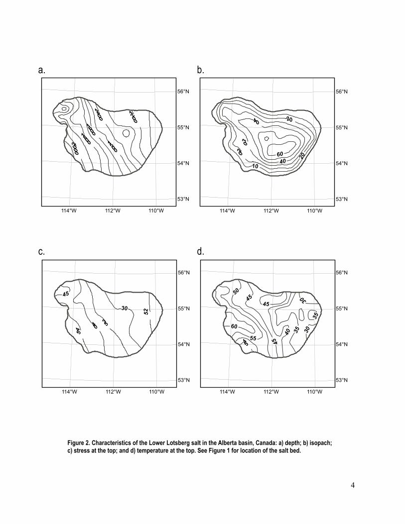
SALT CHARACTERISTICS The Middle Devonian Elk Point Group in the Alberta basin was deposited in a shallow-marine restricted environment that led to the deposition of several extensive and thick salt beds. The lowermost of these salt beds, the Lower Lotsberg, covers an area of ~65,500 km2 in east-central Alberta, is found at depths that vary between <1,100 m and >2,100 m, and reaches >60 m in thickness (Figures 2a and 2b). The vertical stress (weight of the overburden) at the top of the Lower Lotsberg salt varies between <25 MPa and >45 MPa (Figure 2c), and temperatures vary between ~30oC and >60oC (Figure 2d). Overlying salt beds, such as Upper Lotsberg and Prairie Evaporite, reach up to 200 m in thickness. The salt is recrystallized evaporitic salt of exceptional purity (>90%), with no clay and anhydrite seams that are usually found in salt beds. Shale layers embed the Lower Lotsberg salt. Because the region is located at the shallow edge of the Alberta basin, where no tectonic activity took place, there are no fractures, faults or folds in the overlying rocks. Thus, no joints and fissures have opened through flexure, and the degree of lateral continuity of the salt and of the overlying strata is large. As with all natural, laterally-continuous salt beds, it can be safely assumed that the Lower Lotsberg salt is impermeable. If, for some reason a CO2-filled cavern were breached, the escaped CO2 will be confined by the overlying regional-scale aquitards and aquicludes in the sedimentary succession. If a cavern is filled with a fluid at an initial pressure , in the long term the pressure 0p p inside the cavern may change as a result of (Berest et al., 2000): salt creep; thermal expansion of the cavern fluid; leakage along the well bore; flow of the fluid out of the cavern into the adjacent strata; and additional salt solution or precipitation in the cavern. Since salt is insoluble in CO2 and salt beds have such low permeability (<10-21 m2; Bredehoeft, 1988; Beauheim & Roberts, 2002) that practically they are impermeable, the last two situations do not apply for the case of CO2 sequestration in salt caverns. If the mining and filling well is properly completed and sealed, no leakage should occur (otherwise it would defeat the cavern purpose!). Because supercritical CO2 is highly compressible compared with a liquid such as brine, CO2 thermal expansion does not play an important role unless CO2 is placed in the cavern in a cold state at a pressure close to lithostatic, and then is heated in situ after cavern closure. For the purpose of this analysis and for practical reasons, it is assumed that the CO2 temperature at cavern sealing or shortly after is equal to the initial formation temperature. Thus, the only significant mechanism for pressure change in the cavern is salt creep. Salt is a viscoplastic substance and slow creep tends to dissipate shear stresses over times of several hundred years, hence the initial and final stress states in salt are isotropic ( maxmin HHV σσσ == ; where
Vσ and Hσ are the vertical and horizontal stresses, respectively). Steady-state salt creep is assumed to be a power function of the shear stress σ of the form:
n
=
00 σ
σεε && (1)
where HV σσσ −= is the shear stress, 0σ is a reference stress, ε& is the shear strain rate, and 0ε& is the shear strain rate at 0σ ). The power creep law holds only for a limited stress range (Munson and Dawson, 1982), but mine-back analysis and long-term laboratory data suggest that n=3 and 0ε& =0.001–0.002 year-1 for σ <10 MPa (Rothenburg et al., 1993; 2002a). After a few years since cavern sealing, σ will be <10 MPa and use of the power law for salt creep is appropriate. MODEL FORMULATION Cavern Closure Rate A salt cavern would be dissolved approximately as a sphere or a prolate (flattened) spheroid, and a spherical cavern is assumed in the following, for easier mathematical treatment. Owing to spherical
3
����� ����� �����
���
���
���
��
����
����
����
����
����
����
��
��
��
��
�� ��
��
��
��
��
��
��
��
��
��
��
��
��
��
��
����
��
�� ��
�� ��
������������� ������� ���������������������������������������������������������������������������� �� �������������������������������������������������������������� ������� ���������������������
����� ����� �����
���
���
���
��
����� ����� �����
���
���
���
��
����� ����� �����
���
���
���
��
��
��
��
4
symmetry, the main stresses are radial and tangential ( rσ and θσ , respectively), and the radial stress equilibrium must be satisfied:
0)(
2 =−
+rdr
d rr θσσσ (2)
where θσσσ −= r is the shear stress in a spherical field. The principal strain rates (ε& ) in the salt bed are radial and tangential, and are expressed by:
drdv
r =ε& and rv
=εθ&
where ν = ν(r) is the velocity of salt creep outside the cavern. The salt-incompressibility condition requires that 02 =+ θεε &&r , resulting in:
2
0
−=
ravv (3)
where is salt velocity at the boundary of the cavern of radius a. 0v Manipulation of relations (1)-(3) and integration leads to (Rothenburg et al., 2002b):
np
na
v
−⋅= ∞
0
00
32 σ
σε& (4)
where ∞σ is the initial in situ stress in the salt bed and p is cavern pressure. Rather than expressing the cavern closure in terms of creep velocity at the cavern boundary ( ), it is better to express it in terms of the relative reduction in the cavern volume V , resulting in:
a&
np
nVV
−⋅= ∞
0
0 32
3σ
σε&& (5)
Pressure Increase in the Cavern Because salt conducts heat relatively rapidly and because of the thermal capacity of the earth at depth, the temperature in the cavern will equilibrate rapidly by comparison with the slow cavern pressurization. This allows to assume that the temperature in the cavern is constant and equal to the initial salt temperature. For an isothermal process, the equation of state (EOS) for the fluid in the cavern can be written in differential form as:
ppC
VV
p&&
= (6)
where 1−
∂∂
=r
r
r
rp V
pVpC is the compressibility coefficient expressed in terms of reduced pressure
cr p
pp = , temperature c
r TT
=T and volume )/( cc
r pRTV
=V (for real gases < 1). For COpC 2, the
critical temperature and pressure are T =304.26K (31.1c
p
oC) and =7.38 MPa (Span & Wagner, 1996). The gas compressibility coefficient, C , can be derived from the gas EOS, such as Peng-Robinson.
cp
5
Substitution of eq. (6) into eq. (5) finally leads to:
−⋅= ∞
00
323
σσ
εp
ndtdp
pC p & (7)
which expresses the increase in cavern pressure as the salt closes in. To generalize the solution, eq. (7) can be written in dimensionless form as:
np ptdpd
pC
)~1(~~
~ −= (8)
where ∞
=σ
pp~ and tn
tn
⋅= ∞
00
323
σσ
ε&~ .
The solution to eq. (8) depends explicitly on the ratios of initial in situ stress to critical gas pressure, cp/∞σ , and of initial cavern pressure and initial in situ stress, ∞σ/0p
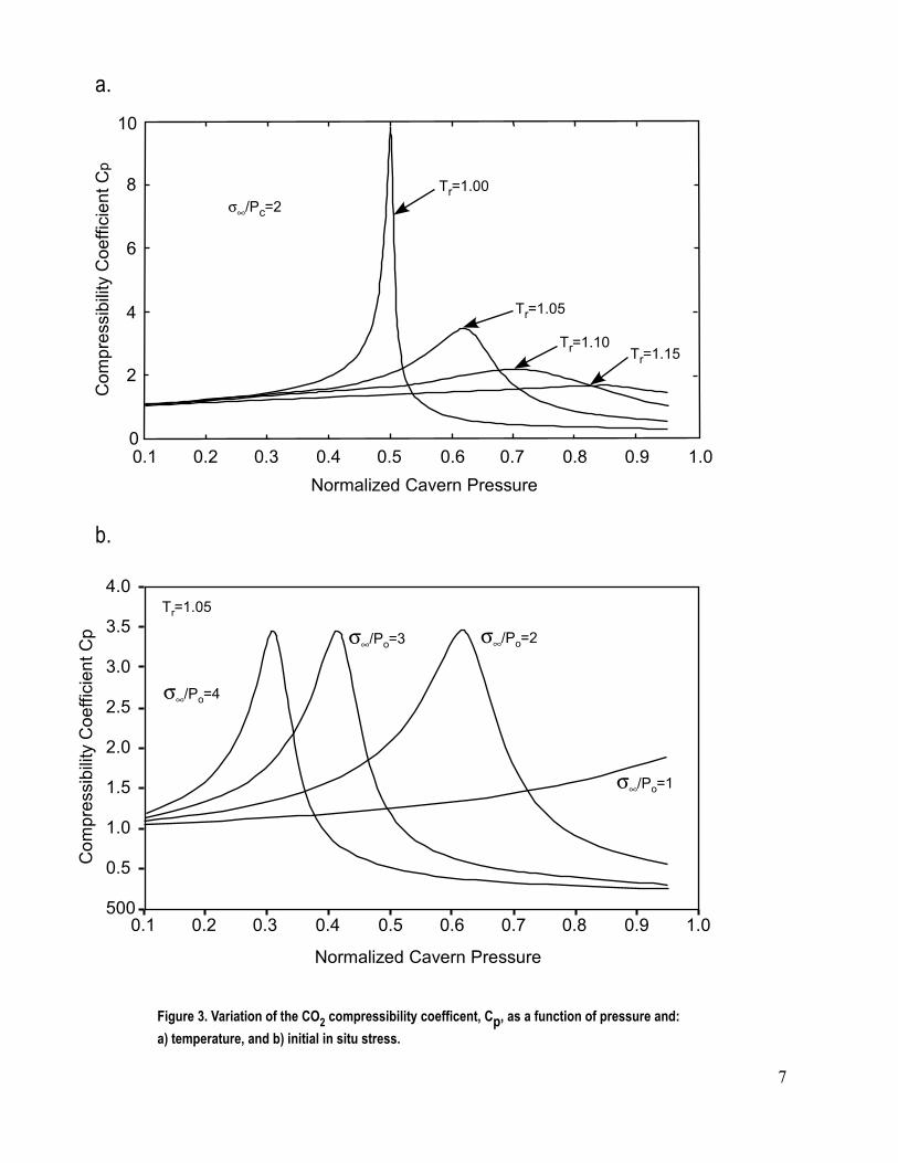
pC, and depends implicitly on the
gas reduced temperature, T , through the compressibility coefficient . To illustrate this dependency,
Figure 3 shows the variation of , derived from EOS, as a function of cavern pressure, and initial temperature and stress in the salt bed.
r
pC
CLOSURE OF A CO2-FILLED CAVERN The characteristic values for Middle Devonian salt beds in northeastern Alberta indicate that the dimensionless parameters in eq. (8) vary as follows: cp/∞σ ≈4, ∞σ/0p >0.2, and T ∈[1.02-1.15]. If a salt cavern is filled under brine hydrostatic conditions, then the initial cavern pressure, , is approximately half of the weight of the overburden. For
r
0p
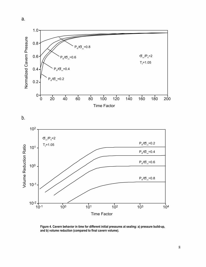
0σ =10 MPa and 0ε& =0.002 yr-1, t~ =0.063 t (i.e., the time factor ~16 years real time). Figure 4 shows the pressure build-up inside the cavern, and the reduction in cavern volume (compression) in time, for an initial cavern pressure equal to half of the lithostatic ( cp/∞σ =2), and temperature of 46oC (T =1.05). The dimensionless volume reduction is defined as the reduction in volume in relation to the current cavity volume, i.e., ( . The pressure build-up is relatively rapid at the beginning (
r
tVVV /)0 −
~ <60), and becomes very slow after pressure in the cavern reaches ~90% of the in situ stress in the salt bed. The effect of initial pressure at the time of cavern sealing, , on pressure inside the cavern is lost for large times (
0pt~ >90) (Figure 4a), but it is significant for the final volume reduction (Figure 4b), hence
on ground subsidence. For example, the cavern shrinks to approximately a fifth of its initial size for ∞σ/0p =0.4, to approximately half of its original size for ∞σ/0p =0.6, but only by ~14% for
∞σ/0p =0.8 (Figure 4b). Volumetric changes are significant (and relatively “fast”) in the early life of the cavern ( t~ <30). After that the cavern volume stabilizes, with negligible rates of change (closure) over time. The effect of temperature on cavern volumetric changes, although less dramatic than that of initial pressure, is also important because of the effect of temperature on the compressibility coefficient C (see Figure 3a). The relative volumetric reduction is smaller for temperatures close to the critical point than for higher temperatures, but the rate of increase in cavern compression diminishes as the temperature increases. For example, for
p
cp/∞σ =2 and ∞σ/0p =0.8, the ultimate reduction in volume cavity is 14%, 40% and 45% for T =1.05, 1.10 and 1.15, respectively. r
6
σ∞�����
����
�����������
�����
� � � � � � �
�
�
�
�
� �
����������������������� ��
���!�����"���#$����%%�����#��!
�
����������������������� ��
���!�����"���#$����%%�����#��!
�� � � � � � � �
�
�
��
�
��
�
��
σ∞�����
σ∞�����
σ∞�����
�����
σ∞����
��
��
��������������� �� ����������� ��������������� ������������������������� �� ���������������
���������������������������������������������
7
���������
� �����
��������
��
���� ��� ��� ��� ��� �������
����
���
���
���
��σ∞����
��σ∞����
��σ∞����
��σ∞����
σ∞�����
�������
��
��
�
���������
��� �� �� �� ��� ��� ��� ��� ��� ���
���
���
���
���
���
��σ∞����
��σ∞����
��σ∞����
��σ∞����
���
� � ���!
�"�������##���
σ∞�����
�������
������������� ����������� ����������������� ��� ������������������������ ������������������������� �������������������� ���������������� �������� ��������
8
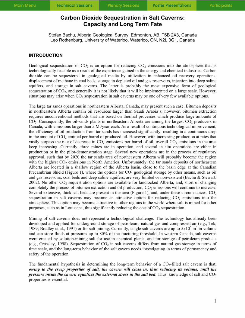
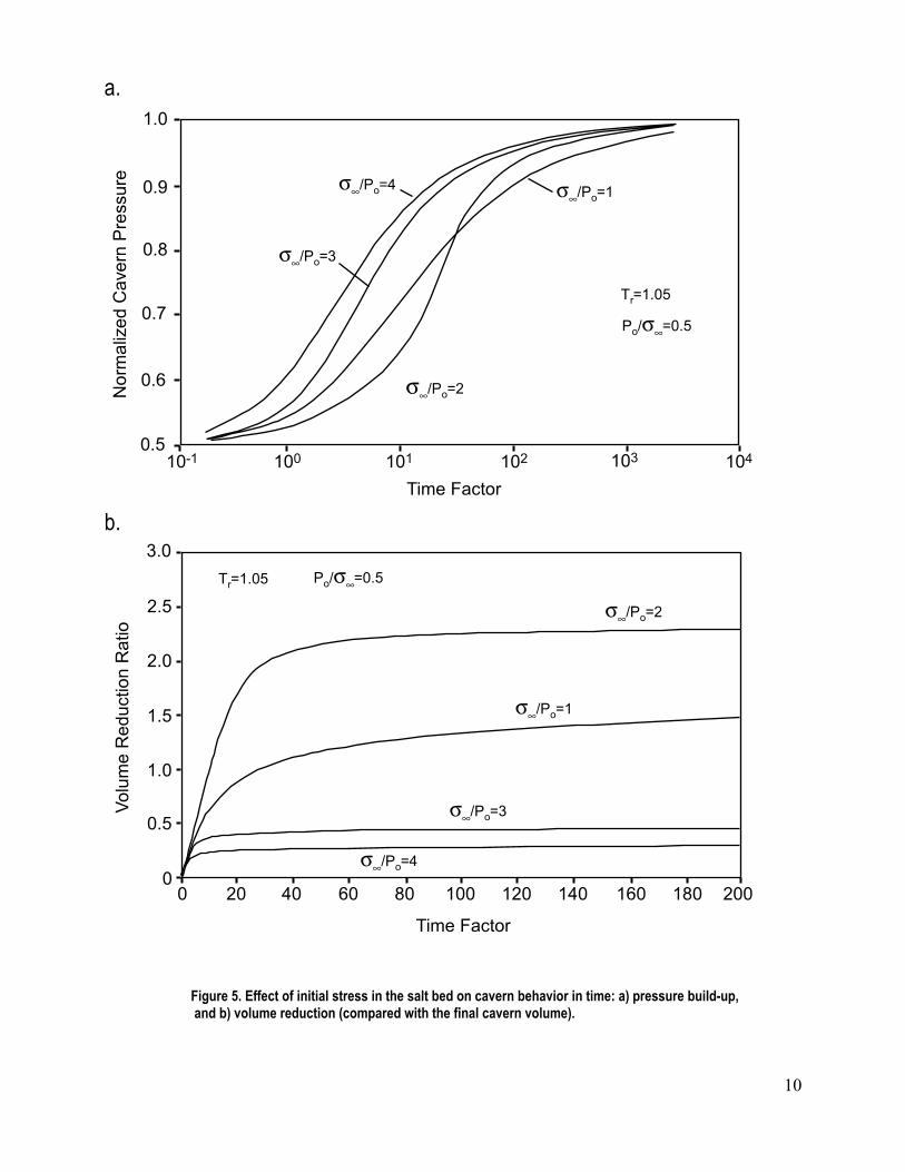
The cavern pressure build-up and volumetric reduction are significantly affected by the magnitude of the initial in situ stress in the salt bed. This effect is due to the increase in the gas (CO2) compressibility coefficient in the vicinity of the critical point (Figure 3b). Due to this effect, the pressure build-up and volumetric changes depend ultimately on the initial stress in the salt bed (expressed by the ratio cp/∞σ ), as shown in Figure 5 for the case of an initial cavern pressure equal to half of the initial i situ stress (
n∞σ/0p =0.5). Pressure in the cavern increases relatively rapidly to ~90% of the lithostatic, t~ ∈[2, 100],
depending on the initial stress and cavern pressure, after which increases slowly. The reduction in cavern volume is rapid at the beginning ( t~ <5-30, depending on the initial stress), after which it is very slow (Figure 5b). The ultimate reduction is significant for low stresses, but less so for high initial stress (e.g., it drops from 70% of the initial volume for cp/∞σ =2 to 77% of the initial volume for cp/∞σ =4). The peculiar behavior of the pressure build-up and volumetric reduction for initial stresses close to the CO2 critical pressure ( cp/∞σ =1), i.e., the position of this curve between those corresponding to higher in situ stresses (Figure 5) is due to the CO2 behavior in the vicinity of the critical point. APPLICATION Cavern closure occurs during cavern mining, filling with CO2, and after sealing. During solution mining the pressure in the cavern can be assumed to be constant and equal to the hydrostatic pressure of the brine. During cavern filling, the brine is displaced by CO2, with the pressure in the cavern still maintained at the initial brine hydrostatic pressure. Only after cavern sealing, the pressure starts to build up. To estimate the final cavern volume and ground subsidence, the cavern volumetric reduction must be estimated for each stage, the cavern volume at the end of each stage becoming the initial volume for the next one. If a salt cavern of 100 m in diameter (a=50 m) is mined over a 3 year period at a depth of ~1200 m in a salt bed where the in situ stress and temperature are: ∞σ ~28 MPa and T =37oC, and the hydrostatic brine pressure is ~14 MPa. Assuming a constant volumetric rate of solution mining, direct application of eq. (5) leads to a decrease in cavern volume during mining of ~5,925 m
0p3 (~1%). If the cavity is filled with
CO2 during the next 3 years by displacing the brine at constant pressure, the cavern will shrink by another ~11,850 m3. Finally, after cavern sealing, the ultimate volumetric reduction due to salt creep is ~78,500 m3. The total volume lost during cavern mining, filling with CO2 and after sealing is ~96,300 m3, or ~18% of the original cavern volume. This cavern at 1200 m can be considered as a point source in relation to the ground surface, resulting in a subsidence of ~5 mm, of which half will occur in the first 160 years ( t~ ~10). The cavern will sequester ~500 kt CO2 (0.5 Mt) at supercritical conditions and density of 910 kg/m3. The cavern closure will be very slow, pressurizing the CO2 to ~94% of the initial stress in the salt bed in more than 4,000 years. CONCLUSIONS Geological sequestration of CO2 is a mitigation option for significantly reducing CO2 emissions into the atmosphere that is immediately available and technologically feasible. Injection technologies have been developed for the storage of petroleum products and natural gas, and for the disposal of hazardous wastes. Various operations in North America inject CO2 into deep formations for enhanced oil recovery and for acid gas disposal, while various liquid wastes are disposed of by injection into permeable formations and salt caverns. Although the least economic of the various means of CO2 geological sequestration, injection and sealing of CO2 in salt caverns is a method that may be the only alternative in regions that lack other sequestration means, particularly in areas where the sedimentary succession is too thin to allow injection of CO2 in a dense-fluid phase into permeable formations. Such a region is in northeastern Alberta, where bitumen and oil production from tar sands located at the shallow edge of the Alberta basin results in very large CO2 emissions that will significantly increase in the future. Although there are no hydrocarbon reservoirs, aquifers and coal beds suitable for CO2 sequestration in the region, extensive, thick salt beds may provide a partial solution for reducing CO2 emissions into the atmosphere.
9
���������
� ���������������
���� ��� ��� ��� ������
���
���
���
���
���
���
σ∞�� �
σ∞�� �
σ∞�� �
σ∞�� �
�� ����
��σ∞ ���
��
��
�
���������
!��
� �"���#�$�������%%���
��� �� �� �� ��� ��� ��� ��� ��� ���
���
���
���
���
��� σ∞�� �
���
σ∞�� �
σ∞�� �
σ∞�� �
�� ���� �
�σ∞ ���
������������� ������� ����� �������� ������ ��������������������������� ���������������������������������������������� ���������������� �� �����������������������
10
Owing to the creep properties of salt, a cavern filled with supercritical CO2 will close in, thus reducing its volume, until the pressure inside the cavern equalizes the external stress in the salt bed. Because of the intermediate compressibility of supercritical CO2, cavern pressurization will be gradual and much slower than for a liquid, but faster than for a gas such as methane (Ehgartner, 1994). As a result, for all practical purposes, it can be assumed that the thermal field inside and outside the cavern will equalize rapidly. The isothermal pressurizing of a spherical salt cavern can be described mathematically by an ordinary differential equation that can be solved explicitly to examine the long-term behavior of the cavern in terms of pressure build-up and reduction in cavern volume. The analysis shows that, at the beginning, the pressure build-up in the cavern is rapid, reaching close to 90% of the stress in the surrounding salt. After a relatively short period of time (tens of years), the pressure build-up becomes extremely slow, and it does not depend anymore on the initial cavern pressure with respect to the initial stress in the salt bed. The pressurizing process continues then for hundreds and thousands of years. Similarly, the reduction of cavern volume is significant at the beginning, after which it becomes negligible. The cavern closure and pressuring depend strongly on the initial pressure in the cavern at sealing, indicating that it is desirable to “overfill” the cavern by injecting CO2 under high pressure (greater than hydrostatic), close to the in situ stress. In such cases, the volume reduction as a result of cavern closure is smaller by 10-15% than when filling with CO2 under hydrostatic conditions. The result is that the CO2 sequestration capacity is increased, while the effect of flexure stresses in the overlying strata is reduced, therefore enhancing the safety of the injection well after cavern sealing. Calculations show that, for conditions specific to salt beds in northeastern Alberta, a single cavern of 100 m in diameter may hold 0.5 Mt CO2. While a single cavern may not satisfy the needs of large CO2 emitters, arrays of such caverns can be built in extensive and thick salt beds in the Alberta basin and elsewhere with similar conditions. REFERENCES Bachu, S. & Stewart, S. 2002. Geological sequestration of anthropogenic carbon dioxide in the Western
Canada Sedimentary Basin. Journal of Canadian Petroleum Technology, 41:2, 32-40. Berest, P., Brouard, B. & Durup, J.G. 2000. Shut-in pressure tests: case studies. In: Proceedings of
Solution Mining Research Institute 2000 Fall Meeting. Bradley, R.A., Watts, E.C. & Williams, E.R. 1991. Limiting Net Greenhouse Gas Emissions in the U.S.
Vol. 1, Report to the US Congress, US DOE. Beauheim, R.L. & Roberts, R.M. 2002. Hydrology and hydraulic properties of a bedded evaporate
formation. Journal of Hydrology, 259, 66-88. Bredehoeft, J.D., 1988. Will salt repositories be dry ? EOS, Trans. AGU, 69:9, 121. Crossley, N.G. 1998. Conversion of LPG salt caverns to natural gas storage “ A Transgas experience”;
Journal of Canadian Petroleum Technology, 37:12, 37-47. Ehgartner, B.L. 1994. Long-term sealing analyses for US Strategic Petroleum Reserve (SPR) caverns.
Report SAND92-2891, Sandia National Laboratories, Albuquerque, NM. Munson, D.E. & Dawson, P.R. 1982. A transient creep model for salt during loading and unloading.
Report SAND82-0962, Sandia National Laboratories, Albuquerque, NM. Rothenburg, L., Frayne, M.A. & Mraz, D.Z. 1993. Application of two and three dimensional numerical
models for intact salt rock. In: Innovative Mine Design for the 21st Century (Bawden, W.F. & Archibald, J.F., eds.) Balkema, 609-620.
Rothenburg, L., Dusseault, M.B. & Mraz, D.Z. 2002a. On the third-power creep law for salt in mine conditions. In: Basic and Applied Salt Mechanics: Proceedings of the Fifth Conference on Mechanical Behavior of Salt, MECASALT V, Bucharest, Romania, 9-11 August 1999 (Cristescu, N.D., Hardy Jr., R.R. & Simionescu, R.O., eds.), Balkema, Lisse (Netherlands), 171-176.
Rothenburg, L., Dusseault, M.B. & Bachu, S. 2002b. Closure of a spherical cavity in salt: an infinite medium solution for long-term gas sequestration studies. In: Mining and Tunneling Innovation and Opportunity, Proceedings of the 5th North American Rock Mechanics Symposium (NARMS) and 17th Tunnelling Association of Canada (TAC) Conference, Toronto, ON, July 7-10, 2002, (R. Hammah, W. Bawden, J. Curran and M. Telesnicki, eds.), University of Toronto Press, v. 2, 1259-1266.
11
12
Span, P., & Wagner, W. 1996. A new equation of state for carbon dioxide covering the fluid region from the triple-point temperature to 1100 K at pressures up to 800 MPa; Journal of Chemical Reference Data, 25:6, 1509-1596.
Tek, M.R., ed., 1989. Underground Storage of Natural Gas: Theory and Practice. NATO ASI Series E, Applied Sciences, 171, Kluwer, Boston, MA, 458 p.


![Carbon Sequestration: Developing an assessment of ... · Carbon sequestration is the permanent storage of carbon dioxide gas [CO 2] for the purpose of mitigating accumulation of CO](https://img.dokumen.tips/doc/110x75/5f14761c719a9240a3157204/carbon-sequestration-developing-an-assessment-of-carbon-sequestration-is-the.jpg)