Embed Size (px)
Citation preview

ECET11
1
CAPACITORS / CAPACITANCE
Enzo Paterno
- Capacitance - Capacitor types - Capacitors in series & parallel - RC Circuit Charging phase - RC Circuit Discharging phase - RC Circuit Steady State model - Source Conversions - Superposition Theorem - Thevenin Equivalent Circuit Source: Introductory Circuit Analysis – Boylestad 10th Ed.
ECET11 CAPACITORS
2 Enzo Paterno
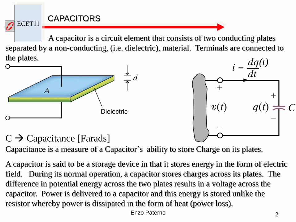
A capacitor is a circuit element that consists of two conducting plates separated by a non-conducting, (i.e. dielectric), material. Terminals are connected to the plates.
A capacitor is said to be a storage device in that it stores energy in the form of electric field. During its normal operation, a capacitor stores charges across its plates. The difference in potential energy across the two plates results in a voltage across the capacitor. Power is delivered to a capacitor and this energy is stored unlike the resistor whereby power is dissipated in the form of heat (power loss).
C Capacitance [Farads] Capacitance is a measure of a Capacitor’s ability to store Charge on its plates.
(t)
ECET11 ELECTRIC FIELD
3 Enzo Paterno
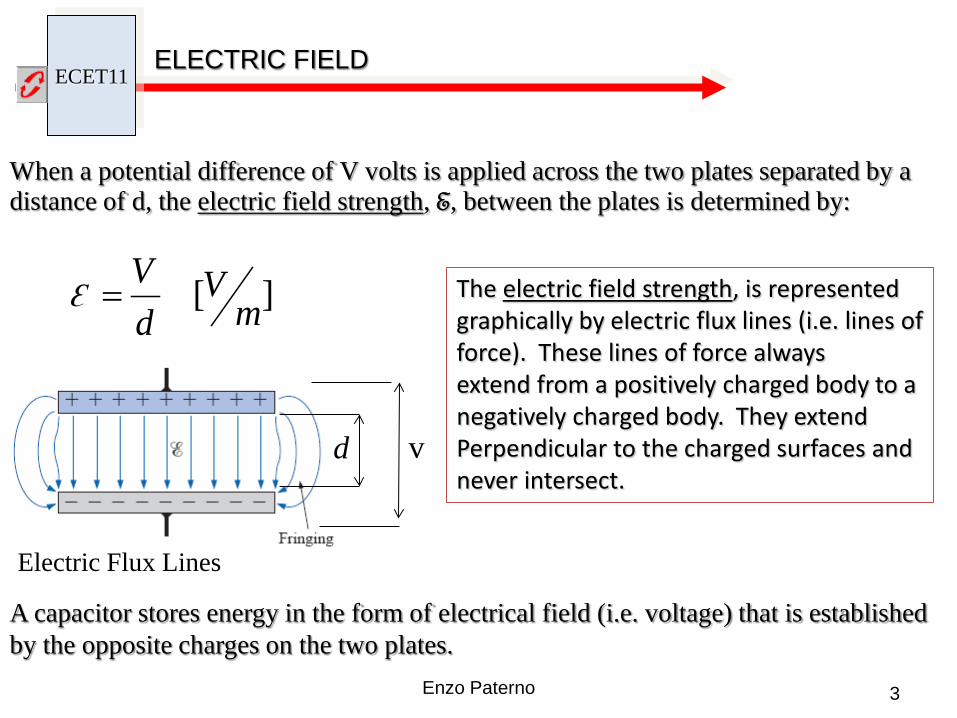
When a potential difference of V volts is applied across the two plates separated by a distance of d, the electric field strength, E, between the plates is determined by:
][ mV
dVE =
A capacitor stores energy in the form of electrical field (i.e. voltage) that is established by the opposite charges on the two plates.
v d
Ɛ The electric field strength, is represented graphically by electric flux lines (i.e. lines of force). These lines of force always extend from a positively charged body to a negatively charged body. They extend Perpendicular to the charged surfaces and never intersect.
Electric Flux Lines

ECET11
4 Enzo Paterno
ELECTRIC FIELD
The force exerted between two charged particles is given by Coulomb’s law:
221
dQkQF =
The electric field strength, ε, at a given point is the force, F, acting on a unit positive charge (Q1 = 1C) at that point:

ECET11 CAPACITOR OPERATION
5 Enzo Paterno
When the capacitor is in a neutral state, both plates have an equal number of free electrons.
•(Insulator)

ECET11 CAPACITOR OPERATION
6 Enzo Paterno
(Electric flux lines)
When a voltage is applied across the plates, electrons are attracted by the positive side of the battery and electrons are repelled by the negative side of the battery. For every electron that leaves one side of the plate, an electron travels to the other side of the plate.
e- e- The electrons can not pass through the dielectric so that plate A starts storing electrons and plate B effectively starts storing positive charges. This process lasts until the plates are fully charged to a potential difference of the source V. The result is a positive charge on plate B and a negative charge on plate A.
B A
V Charging phase process
ECET11 CAPACITOR OPERATION
7 Enzo Paterno
CURRENT APPEARS TO BE FLOWING FROM THE NEGATIVE SIDE OF THE BATTERY TOWARD THE POSITIVE SIDE THROUGH THE CAPACITOR.
IN FACT IT IS NOT SO, BECAUSE NO ELECTRONS CAN FLOW THROUGH THE INSULATOR MATERIAL OR GAP BETWEEN THE PLATES (DIELECTRIC)
THERE ARE IN FACT TWO SEPARATE CURRENTS FROM THE BATTERY TO THE CAPACITOR FROM THE CAPACITOR TO THE BATTERY
ECET11 CAPACITOR OPERATION
8 Enzo Paterno
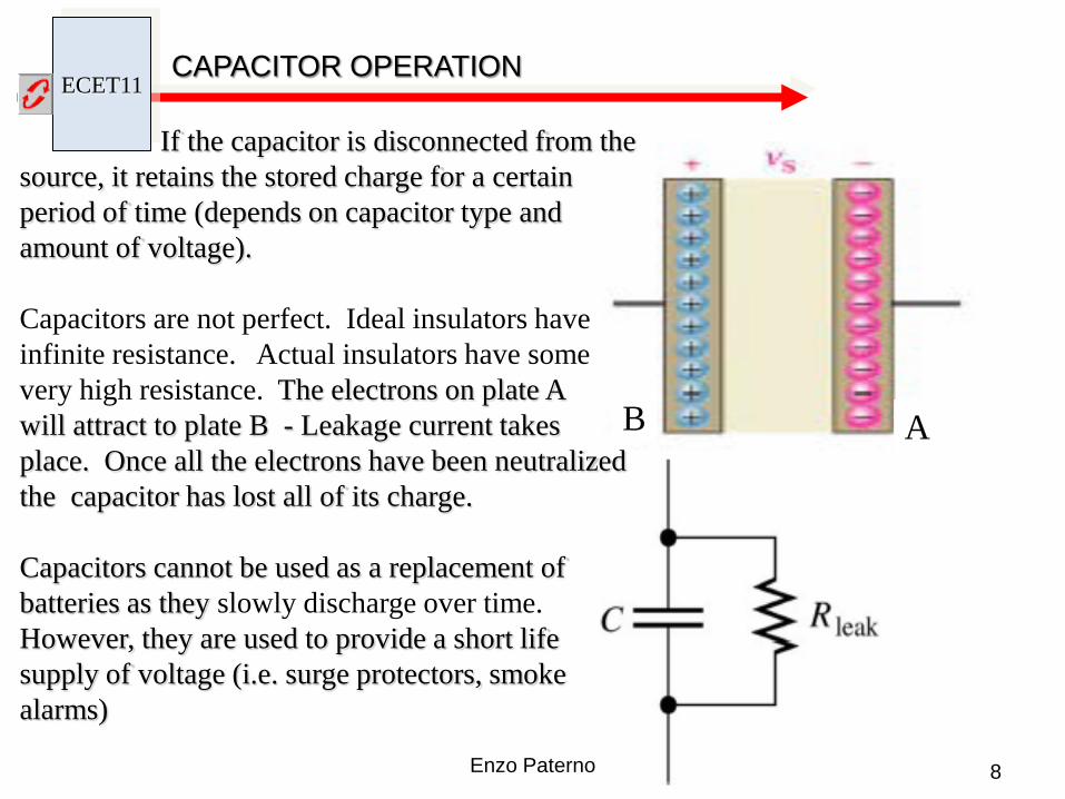
If the capacitor is disconnected from the source, it retains the stored charge for a certain period of time (depends on capacitor type and amount of voltage).
Capacitors are not perfect. Ideal insulators have infinite resistance. Actual insulators have some very high resistance. The electrons on plate A will attract to plate B - Leakage current takes place. Once all the electrons have been neutralized the capacitor has lost all of its charge.
Capacitors cannot be used as a replacement of batteries as they slowly discharge over time. However, they are used to provide a short life supply of voltage (i.e. surge protectors, smoke alarms)
A B
ECET11 CAPACITANCE
9 Enzo Paterno
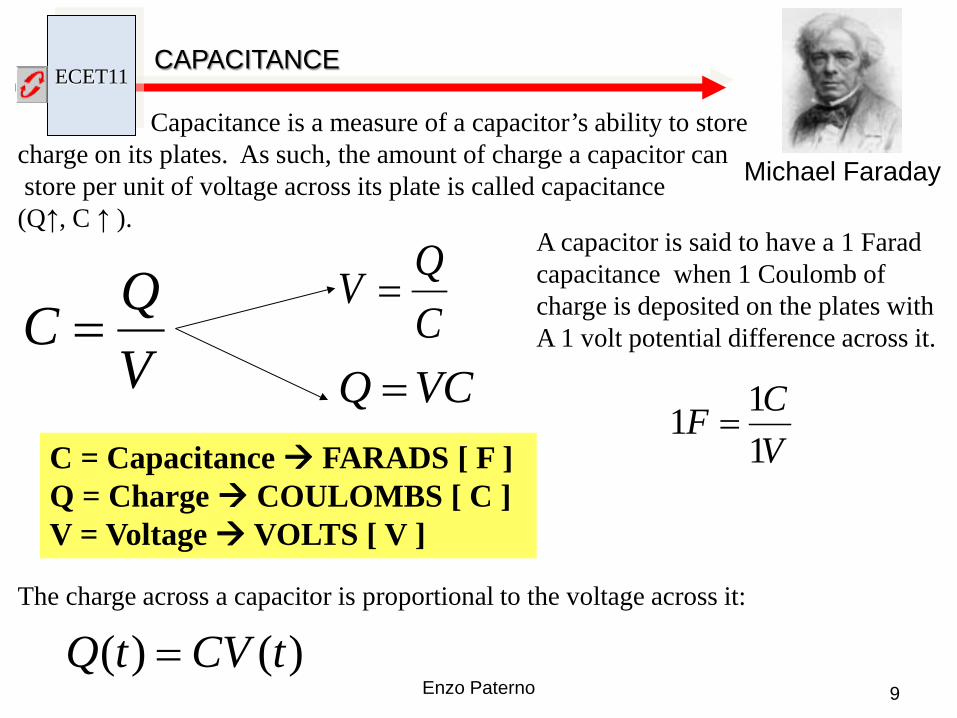
Capacitance is a measure of a capacitor’s ability to store charge on its plates. As such, the amount of charge a capacitor can store per unit of voltage across its plate is called capacitance (Q↑, C ↑ ).
Michael Faraday
VQC = C
QV =
VCQ =C = Capacitance FARADS [ F ] Q = Charge COULOMBS [ C ] V = Voltage VOLTS [ V ]
A capacitor is said to have a 1 Farad capacitance when 1 Coulomb of charge is deposited on the plates with A 1 volt potential difference across it.
VCF
111 =
The charge across a capacitor is proportional to the voltage across it:
)()( tCVtQ =

ECET11 CAPACITANCE
10 Enzo Paterno
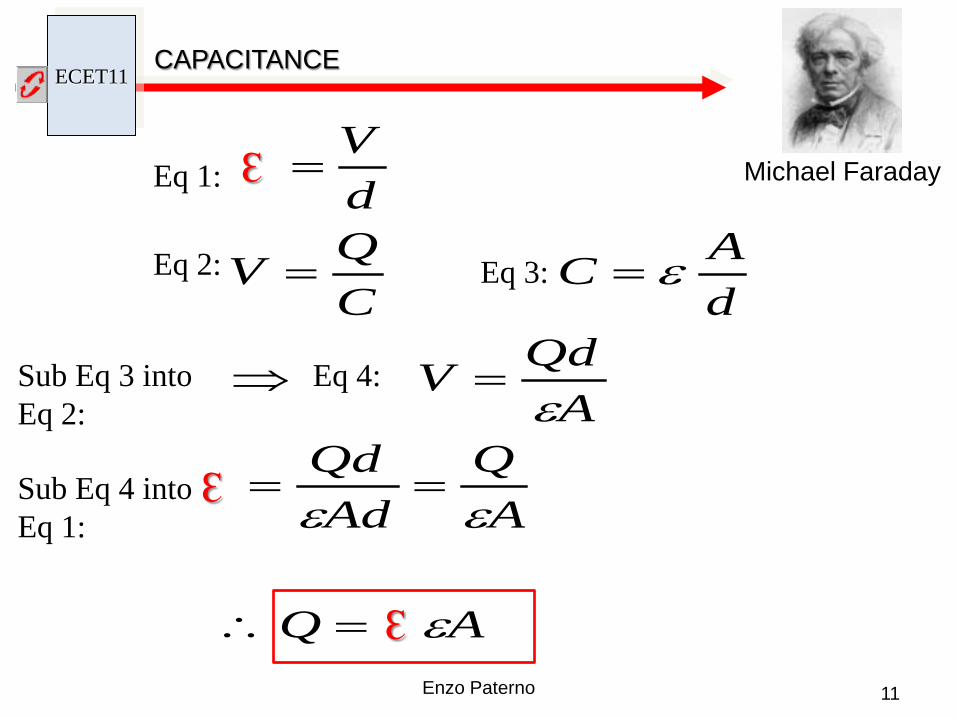
Capacitance can be computed as follows:
Michael Faraday
dAC orεε=
C = CAPACITANCE [ F ] A = AREA OF THE PLATES [ m2 ] d = DISTANCE BETWEEN PLATES [ m ] ε = DIELECTRIC PERMITTIVITY
Permittivity for vacuum εo= 8.85 x 10⁻¹² F/m
ECET11 CAPACITANCE
11 Enzo Paterno
Michael Faraday
AQ
AQ
AdQd
AQdV
dAC
CQV
dV
ε
εε
ε
ε
=∴
==
=⇒
==
=
Ԑ
Ԑ
Ԑ Eq 1:
Sub Eq 3 into Eq 2:
Eq 2: Eq 3:
Eq 4:
Sub Eq 4 into Eq 1:
ECET11 CAPACITANCE
12 Enzo Paterno
Michael Faraday

ECET11 CAPACITOR VOLTAGE BREAKDOWN
13 Enzo Paterno
Every capacitor has a voltage rating. A user must not exceed this voltage rating (i.e. voltage breakdown). Voltage breakdown is the voltage required to break the bonds within the dielectric that will create current flow in the dielectric through the plates
When breakdown occurs, the characteristic of the capacitor becomes that of a conductor (i.e. capacitor shorted)
Clouds
Earth
Atmosphere
+++++++ Lightning is an example of breakdown:
The potential between the clouds and the earth is so high that charge can pass from one to the other through the atmosphere (which acts as the dielectric)

a. C = 3(5 uF) = 15 uF
b. C = ½ (0.1 uF) = 0.05 uF
c. C = 2.5(20 uF) = 50 uF
d. C = (5)(4)/(1/8) (1000 pF) (160)(1000 pF) = 0.16 uF
dAxC rε121085.8 −=
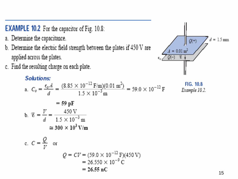
14
15
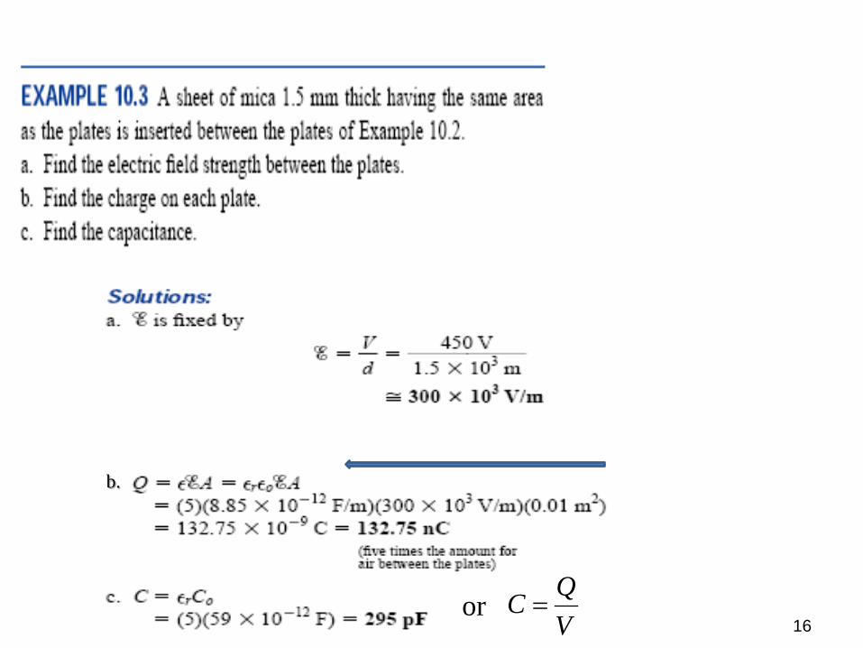
16
b.
VQC =or
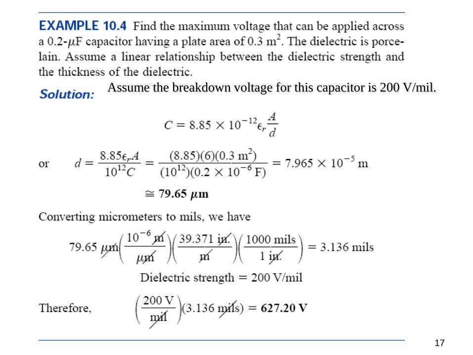
17
Assume the breakdown voltage for this capacitor is 200 V/mil.

ECET11 CAPACITORS
18 Enzo Paterno
There are many types of capacitors and they are characterized by the type of dielectric material used between the conducting plates.
Ceramic Disc
Polyester Film
Tantalum Polypropylene Film
Mylar

ECET11 CAPACITORS
19 Enzo Paterno
There are many types of capacitors and they are characterized by the type of dielectric material used between the conducting plates.
SMT Capacitor
Electrolytic
Radial Lead
Axial Lead
Electrolytic
Variable
Non-polarized
Variable Capacitors
ECET11 CAPACITORS
20 Enzo Paterno
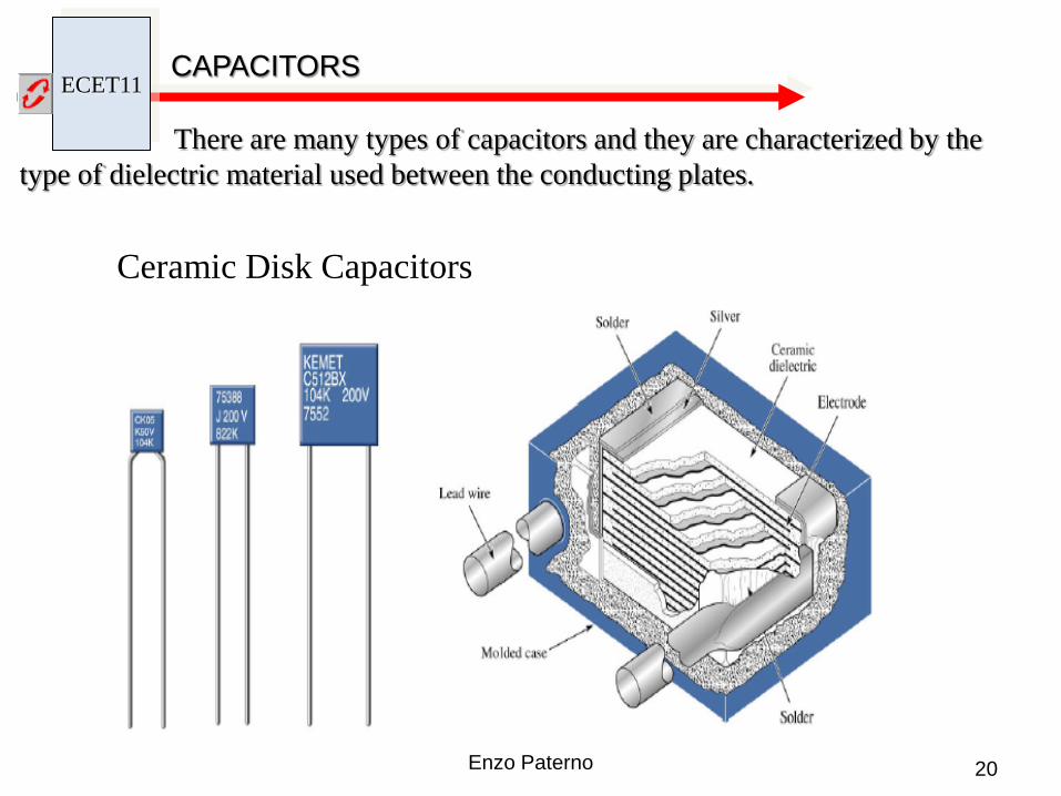
There are many types of capacitors and they are characterized by the type of dielectric material used between the conducting plates.
Ceramic Disk Capacitors
ECET11 CAPACITORS
21 Enzo Paterno
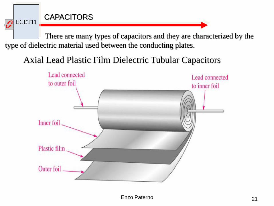
There are many types of capacitors and they are characterized by the type of dielectric material used between the conducting plates.
Axial Lead Plastic Film Dielectric Tubular Capacitors

ECET11 CAPACITORS
22 Enzo Paterno
There are many types of capacitors and they are characterized by the type of dielectric material used between the conducting plates.
Tantalum Electrolytic Capacitors

ECET11 CAPACITOR CODES
23 Enzo Paterno
100,000 pF = 100 nF = .1uF
Ceramic Disc

ECET11 CAPACITOR CODES
24 Enzo Paterno
Electrolytic and large types of Capacitors usually have the value printed on them (i.e. 470uF 25V). Most of the smaller caps have two or three numbers printed on them, The Value is in pF. 105 means 10 x 105 = 1.000.000pF = 1000 nF = 1 uF. Letters added to the value represent the tolerance and in some cases represent the temperature coefficient. A 474J ceramic capacitor means 47 x 104 = 470.000pF and J= 5% tolerance. (470.000pF = 470nF = 0.47uF).
Other capacitors may just have 0.1 or 0.01 printed on them. If so, this means a value in uF. Thus 0.1 means just 0.1 uF. Values marked as 50 or 330 means just pF.

ECET11 CAPACITOR CODES
25 Enzo Paterno

ECET11 CAPACITOR CODES
26 Enzo Paterno
ECET11 CAPACITOR CURRENT & VOLTAGE RELATIONSHIP
27 Enzo Paterno
∫=∴
=
=⇒=∴
==
dttiC
tv
dttiC
tdv
dttdvCti
dttCvdti
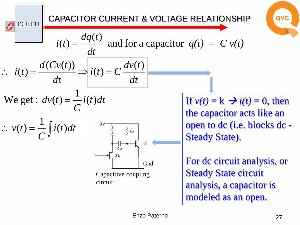
C v(t)q(t) dt
tdqti
)(1)(
)(1)( :getWe
)()())(()(
capacitor afor and )()(
If v(t) = k i(t) = 0, then the capacitor acts like an open to dc (i.e. blocks dc - Steady State). For dc circuit analysis, or Steady State circuit analysis, a capacitor is modeled as an open.
Capacitive coupling circuit
5v
Gnd
ECET11
28 Enzo Paterno
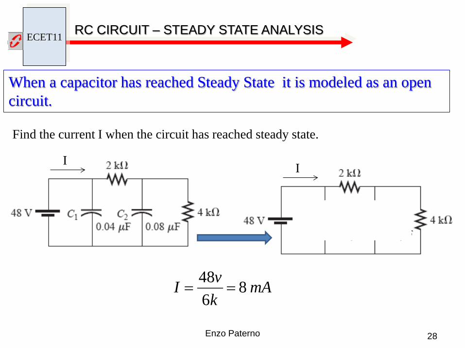
RC CIRCUIT – STEADY STATE ANALYSIS
When a capacitor has reached Steady State it is modeled as an open circuit.
Find the current I when the circuit has reached steady state.
I I
mAkvI 8
648
==
ECET11 CAPACITOR CURRENT & VOLTAGE
29 Enzo Paterno
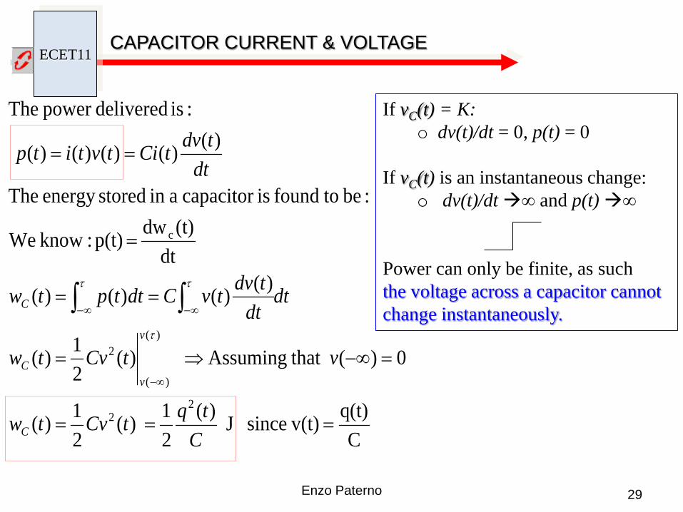
If vC(t) = K: o dv(t)/dt = 0, p(t) = 0
If vC(t) is an instantaneous change:
o dv(t)/dt ∞ and p(t) ∞
Power can only be finite, as such the voltage across a capacitor cannot change instantaneously.
Cq(t) v(t)since J )(
21 )(
21)(
0)( that Assuming )(21)(
)()()()(
dt(t)dw p(t) :know We
:be tofound iscapacitor ain storedenergy The
)()()()()(
:is deliveredpower The
22
)(
)(
2
c
===
=−∞⇒=
==
=
==
−∞
∞−∞− ∫∫
CtqtCvtw
vtCvtw
dtdt
tdvtvCdttptw
dttdvtCitvtitp
C
v
vC
C
τ
ττ
ECET11 CAPACITORS
30 Enzo Paterno
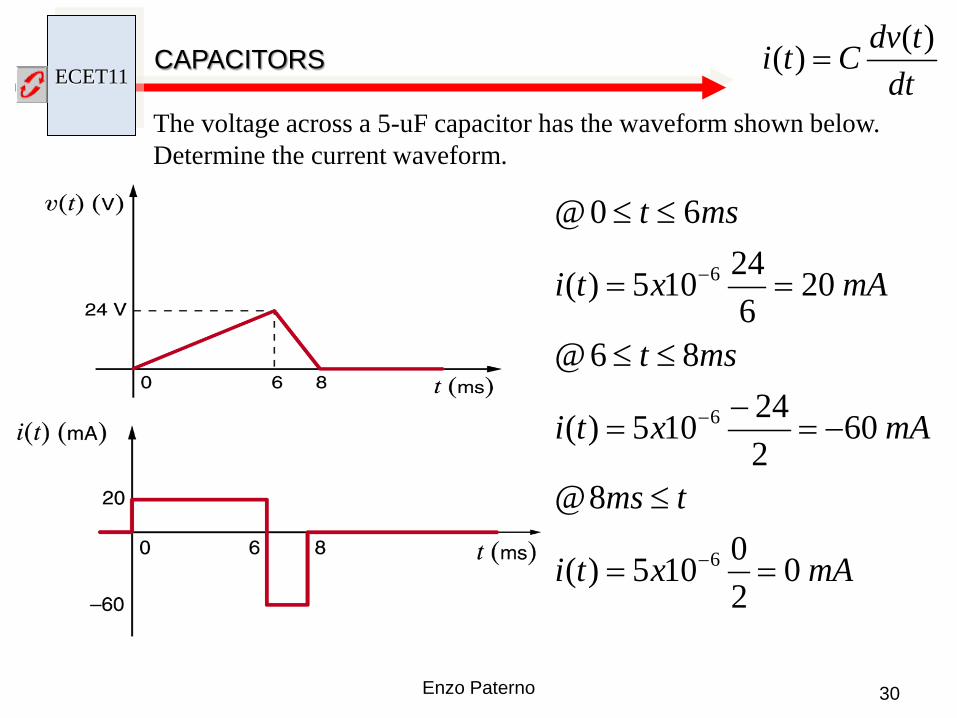
The voltage across a 5-uF capacitor has the waveform shown below. Determine the current waveform.
mAxti
tms
mAxti
mst
mAxti
mst
020105)(
8@
60224105)(
86@
20624105)(
60@
6
6
6
==
≤
−=−
=
≤≤
==
≤≤
−
−
−
dttdvCti )()( =

ECET11 CAPACITORS - Example
31 Enzo Paterno
The voltage across a 5-uF capacitor has the waveform shown below. Determine the Energy at t = 6ms.
)(21)( 2 tCvtwC =
26 )24)(105(21)6( −= xmswC
uJmswC 1440)6( =

ECET11 CAPACITORS IN SERIES
32 Enzo Paterno
Using KVL: )()()()()( 321 tvtvtvtvtv N++++=
∫= dttiC
tvi
i )(1)( ∫∑
=
=
dttiC
tvn
I ii )(1)(
1∫= dtti
Ctv
S
)(1)(
N
n
I iS CCCCCC111111
3211++++=
= ∑
=
Capacitors in series act like resistors in parallel
Current is the same through each element in a series circuit
C1 C2
21
21
CCCCCT +
=

ECET11 CAPACITORS IN PARALLEL
Using KCL: )()()()()( 321 tititititi N++++=
dttdvC
dttdvC
dttdvC
dttdvCti N
)()()()()( 321 ++++=
Capacitors in parallel act like resistors in series
Enzo Paterno 33
N
N
iiP
N
ii
CCCCCC
dttdvCti
++++=
=
=
∑
∑
=
=
3211
1
)()(
Voltage is the same across each branch in a parallel circuit

ECET11 TESLA COIL
34 Enzo Paterno
• A high voltage power supply charges up a capacitor C1. • When the capacitor reaches a high enough voltage, the spark gap (switch) fires. • When the spark gap fires, the energy stored up in the capacitor dumps into a 1:100 step-up transformer. • The primary (L1) is about 10 turns of heavy wire. The secondary (L2) is about 1000 turns of thin wire ( 1:100 ratio). Feed in 10,000 volts, get out 1,000,000 volts. It all happens at a rate of over 120 times per second, often generating multiple discharges in many directions

ECET11 CAPACITORS IN SERIES & PARALLEL
35 Enzo Paterno
Tesla coil designs require a capacitor with large voltage breakdown. Placing capacitors is series increases the voltage breakdown (add each voltage breakdown). However, placing capacitors in series reduces the total capacitance. This banks of capacitors in series are placed in parallel.
Use Power factor correction (PFC) capacitors only. These are used to correct the power factor of the AC connected to the Neon Sign Transformer (NST).

ECET11 CAPACITORS IN SERIES
36 Enzo Paterno http://www.teslacoildesign.com/
CAPACITORS IN SERIES & PARALLEL
MMC: Multi Mini Capacitor

ECET11 TRANSIENT ANALYSIS - CAPACITOR CHARGING PHASE
37 Enzo Paterno
t = 0
vC (0) = 0
@ t = 0+ switch is closed vC (0+) = 0 RC
t
R
RCt
C
RCt
CR
EetV
eEtV
eREtCI
tVtVEt
−
−
−
=
−=
=
+=⇒>
)(
1)(
)(
)()(0@
When
vC (0) = 0
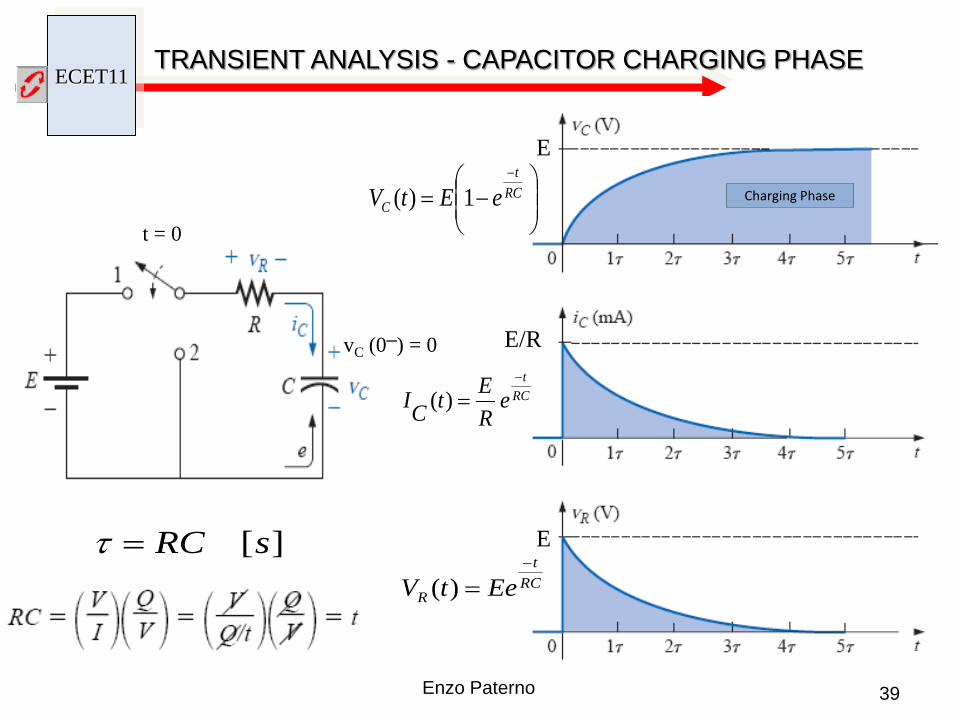
Capacitor is modeled as a short Capacitor is modeled as an open
The RC Circuit provides a 1st order Differential equation. Solving this equation results in:

ECET11 TRANSIENT ANALYSIS - CAPACITOR CHARGING PHASE
Capacitor Charging
volta
ge
time
curr
ent
time
E E/R
ECET11 TRANSIENT ANALYSIS - CAPACITOR CHARGING PHASE
39 Enzo Paterno
t = 0
vC (0) = 0
E
E/R
E
Charging Phase
RCt
R EetV−
=)(
RCt
eREtCI
−
=)(
−=
−RC
t
C eEtV 1)(
][sRC=τ

ECET11 TRANSIENT ANALYSIS - CAPACITOR CHARGING PHASE
40 Enzo Paterno
t = 0
vC (0) = Vi
@ t = 0+ switch is closed vC (0+) = Vi
( )
( ) RCt
iR
RCt
iC
RCt
i
CR
eVEtV
eVEEtV
eR
VEtCI
tVtVEt
−
−
−
−=
−−=
−=
+=⇒>
)(
)(
)(
)()(0@
When
vC (0) = Vi
Capacitor is modeled as a battery Capacitor is modeled as an open
The RC Circuit provides a 1st order Differential equation. Solving this equation results in:
RVE
CIi−
=
Vi
iVE −
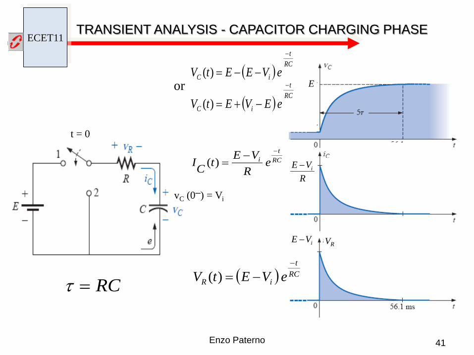
ECET11 TRANSIENT ANALYSIS - CAPACITOR CHARGING PHASE
41 Enzo Paterno
t = 0
RC=τ
vC (0) = Vi R
VE i−
E
VR iVE −
( ) RCt
iR eVEtV−
−=)(
( ) RCt
iC eVEEtV−
−−=)(
( ) RCt
iC eEVEtV−
−+=)(or
RCt
i eR
VEtCI−−
=)(
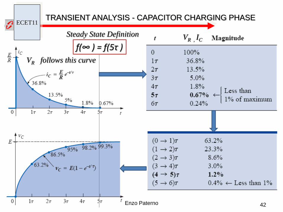
ECET11 TRANSIENT ANALYSIS - CAPACITOR CHARGING PHASE
42 Enzo Paterno
VR , IC
VR follows this curve f(∞ ) = f(5τ )
Steady State Definition
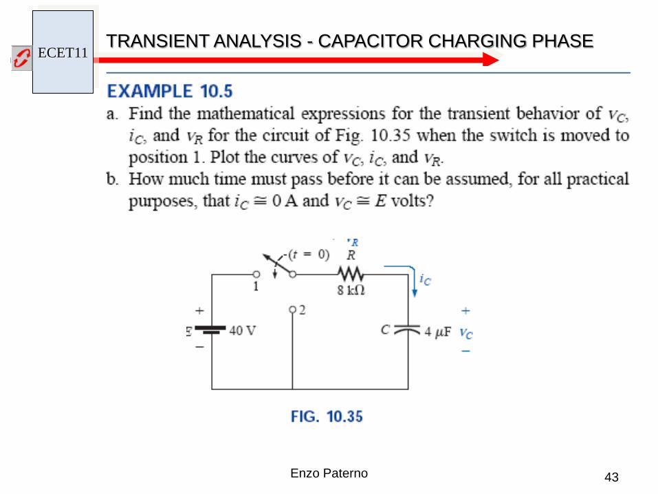
ECET11 TRANSIENT ANALYSIS - CAPACITOR CHARGING PHASE
43 Enzo Paterno
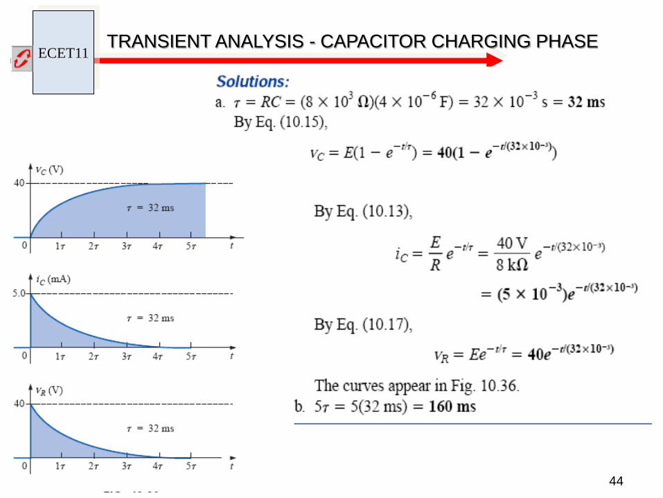
ECET11 TRANSIENT ANALYSIS - CAPACITOR CHARGING PHASE
44

ECET11 TRANSIENT ANALYSIS - CAPACITOR DISCHARGE PHASE
45 Enzo Paterno
@ P1 Charging phase @ P2 Discharging phase
t = 0 vC (0) = 0
t = to
t = to
RCt
C EetV−
=)(
RCt
R EetV−
−=)(
RCt
c eREtI
−−=)(
E
RE
−
E−
Note the current reversal
Note the voltage reversal

ECET11
46 Enzo Paterno
TRANSIENT ANALYSIS - CAPACITOR DISCHARGE PHASE
•CV -

ECET11
47 Enzo Paterno
If the charging phase is disrupted before reaching the supply voltage, the capacitive voltage will be less then E. We call it Vf .
TRANSIENT ANALYSIS - CAPACITOR DISCHARGE PHASE
•CV
•CV
ECET11 SOURCE CONVERSION
48 Enzo Paterno
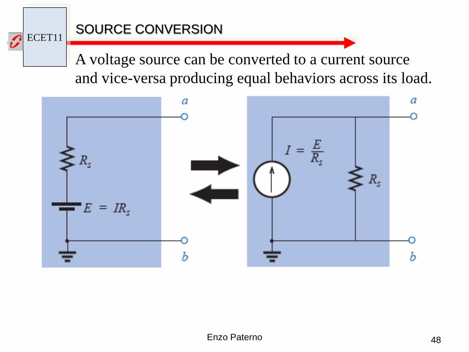
A voltage source can be converted to a current source and vice-versa producing equal behaviors across its load.

ECET11
49 Enzo Paterno
SOURCE CONVERSION
ECET11 TRANSIENT ANALYSIS
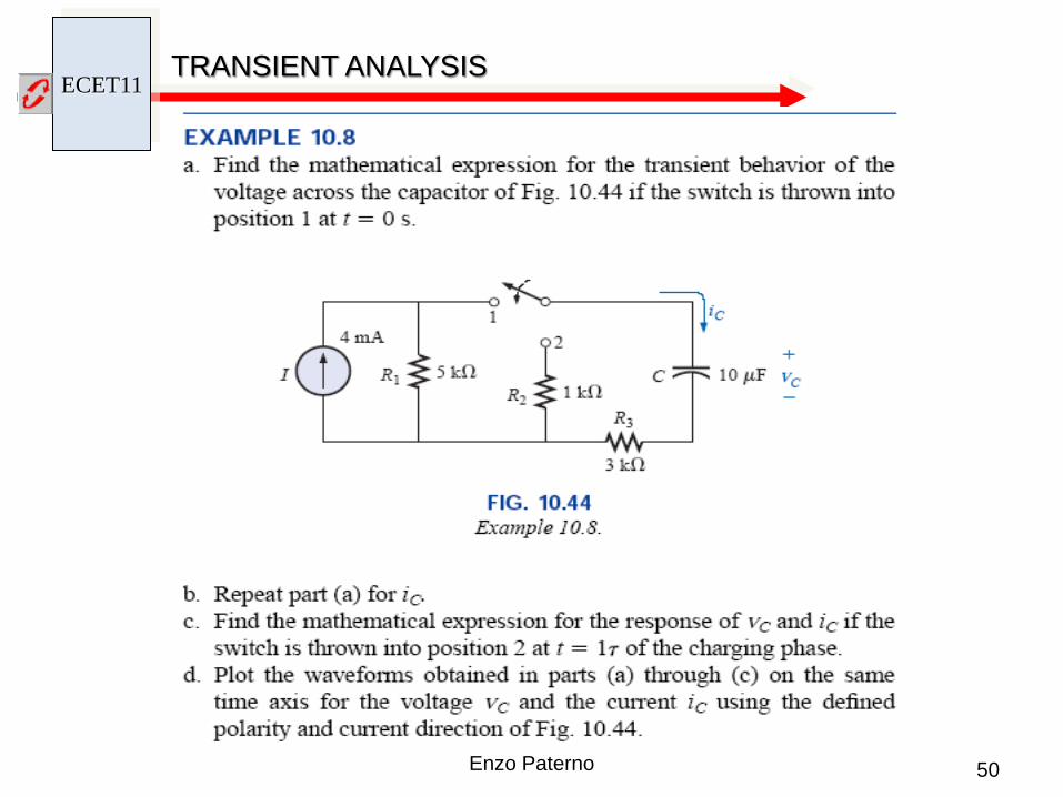
50 Enzo Paterno

ECET11 TRANSIENT ANALYSIS
51 Enzo Paterno
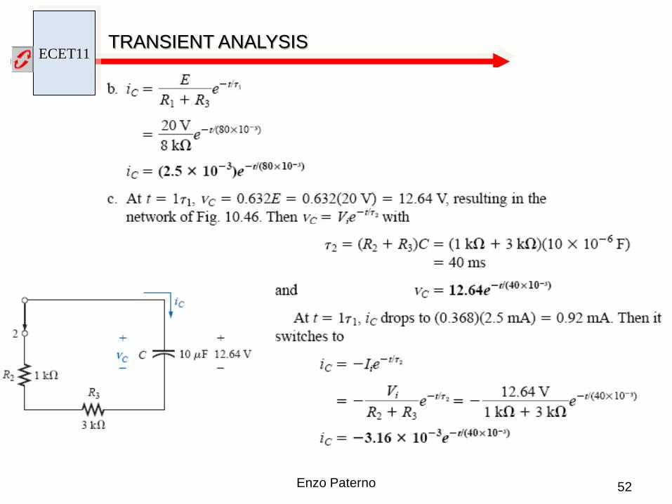
ECET11 TRANSIENT ANALYSIS
52 Enzo Paterno
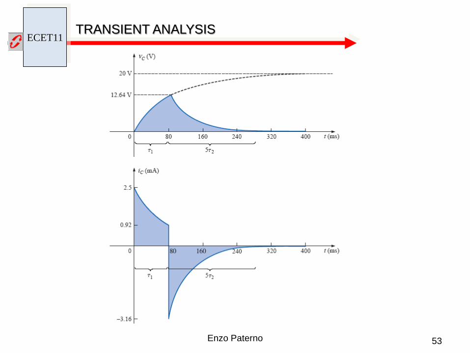
ECET11 TRANSIENT ANALYSIS
53 Enzo Paterno

ECET11 SUPERPOSITION
54 Enzo Paterno
Given a linear circuit, (i.e. described by a set of linear algebraic equations), the superposition analysis technique provides a mean to determine a voltage drop or current by calculating the contribution of each source acting independently and algebraically adding each contribution. Procedure: 1. Remove all sources except one of them by
replacing current sources with an open replacing voltage sources with a short retaining all internal resistance
2. Calculate the desired voltage drop or branch current from that source paying
close attention to polarity or direction
3. Repeat steps 1 and 2 for each additional source acting independently
4. Algebraically add each sources contribution

ECET11 SUPERPOSITION – Example 1
55 Enzo Paterno
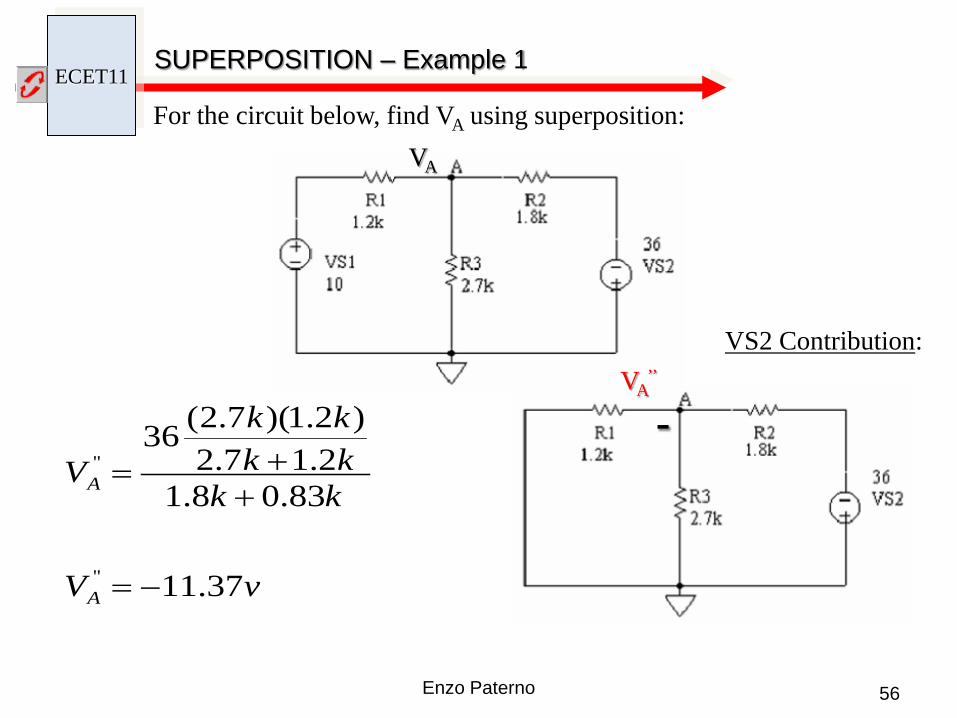
For the circuit below, find VA using superposition:
VA’
VA
VS1 Contribution:
vV
kkkkkk
V
A
A
74.4
08.12.18.17.2
)8.1)(7.2(10
'
'
+=
++=
+
ECET11
56 Enzo Paterno
For the circuit below, find VA using superposition: VA
VA’’
vV
kkkkkk
V
A
A
37.11
83.08.12.17.2
)2.1)(7.2(36
''
''
−=
++=
-
VS2 Contribution:
SUPERPOSITION – Example 1
ECET11
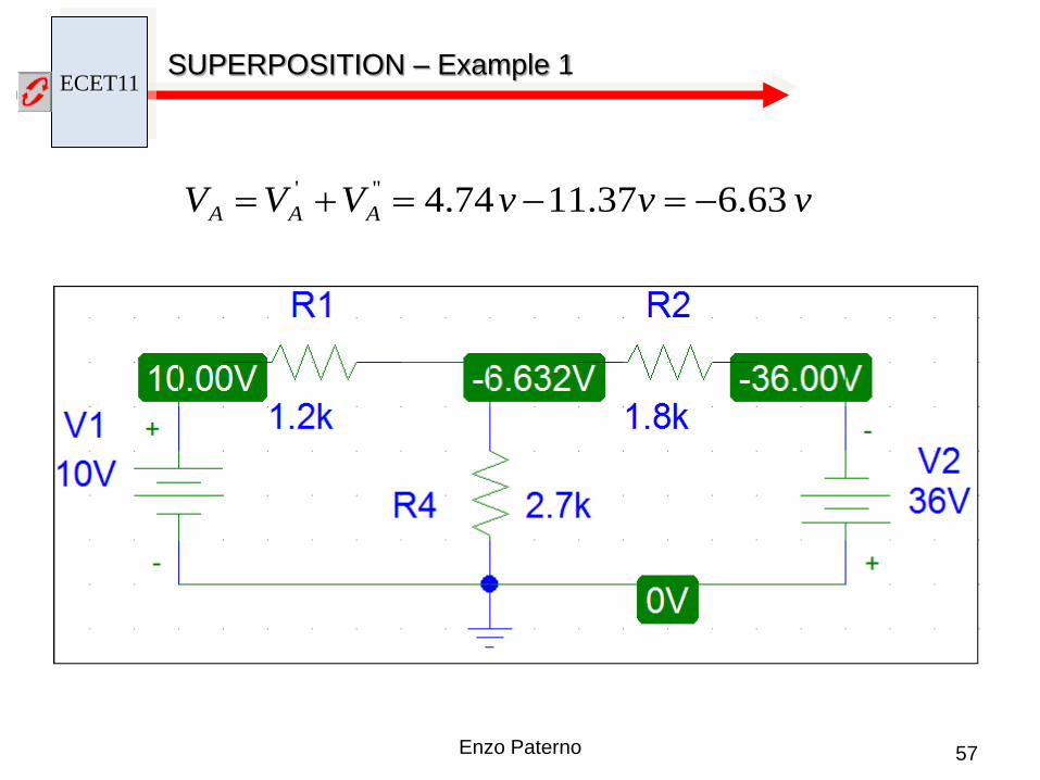
57 Enzo Paterno
vvvVVV AAA 63.637.1174.4''' −=−=+=
SUPERPOSITION – Example 1

ECET11
58 Enzo Paterno
For the circuit below, find VA and VB using superposition:
VA VB
SUPERPOSITION – Example 2

ECET11
59 Enzo Paterno
VS1 Contribution: R2 // R4 = 4705 Ω RL + 4705 Ω = 6705 Ω R3 // 6705 Ω = 5021 Ω
vV
kkkV
A
A
26.22
021.54)021.5(40
'
'
=
+=
VA’ VB
’
vV
kkkV
B
B
62.15
705.42)705.4(26.22
'
'
=
+=
SUPERPOSITION – Example 2
ECET11
60 Enzo Paterno
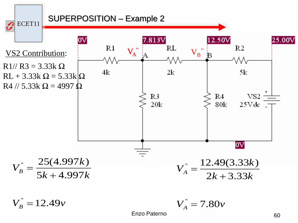
VS2 Contribution: R1// R3 = 3.33k Ω RL + 3.33k Ω = 5.33k Ω R4 // 5.33k Ω = 4997 Ω
vV
kkkV
B
B
49.12
997.45)997.4(25
''
''
=
+=
vV
kkkV
A
A
80.7
33.32)33.3(49.12
''
''
=
+=
VA’’ VB
’’
SUPERPOSITION – Example 2

ECET11
61 Enzo Paterno
vVA 26.22' = vVB 62.15' =
vVB 49.12'' =vVA 80.7'' =
VA VB
vVVV AAA 06.30''' =+= vVVV BBB 11.28''' =+=
SUPERPOSITION – Example 2

ECET11
62 Enzo Paterno
SUPERPOSITION – Example 3
VA
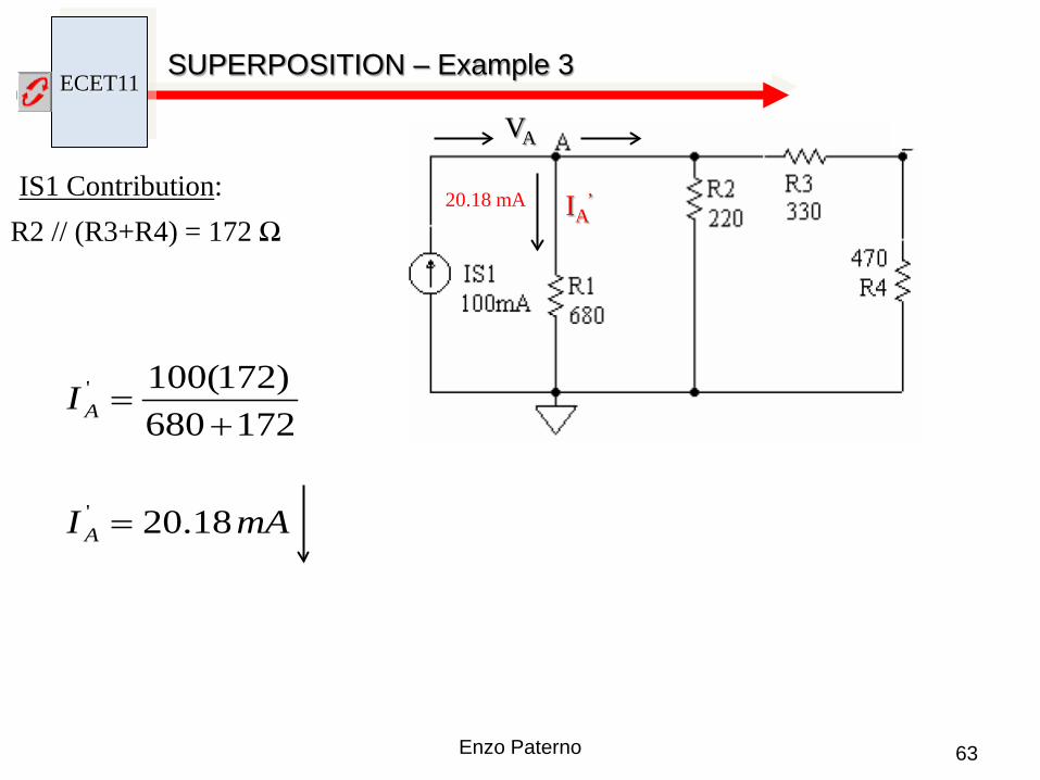
For the circuit below, find VA using superposition:
ECET11
63 Enzo Paterno
SUPERPOSITION – Example 3
IS1 Contribution: R2 // (R3+R4) = 172 Ω
mAI
I
A
A
18.20
172680)172(100
'
'
=
+=
20.18 mA IA’
VA

ECET11
64 Enzo Paterno
SUPERPOSITION – Example 3
VS2 Contribution: R1 // (R3+R4) = 367 Ω
mAI
I
VI
A
A
AA
38.18
680220367
)367(20680
''
''
'''
=
+=
=18.38 mA
IA’’
VA

ECET11
65 Enzo Paterno
SUPERPOSITION – Example 3
mAI A 18.20' =
mAI A 38.18'' =
VA A
I
mAI
mAmAIII AA
80.1
38.1818.20'''
=
−=+=
vV
mAV
A
A
224.1
)680(80.1
=
Ω=
1.224 v
ECET11
66 Enzo Paterno
THEVENIN’S THEOREM
This image cannot currently be displayed.
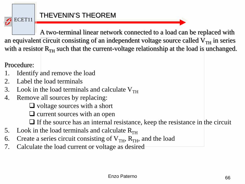
A two-terminal linear network connected to a load can be replaced with an equivalent circuit consisting of an independent voltage source called VTH in series with a resistor RTH such that the current-voltage relationship at the load is unchanged. Procedure: 1. Identify and remove the load 2. Label the load terminals 3. Look in the load terminals and calculate VTH 4. Remove all sources by replacing:
voltage sources with a short current sources with an open If the source has an internal resistance, keep the resistance in the circuit
5. Look in the load terminals and calculate RTH 6. Create a series circuit consisting of VTH, RTH, and the load 7. Calculate the load current or voltage as desired

ECET11
67 Enzo Paterno
THEVENIN’S THEOREM – Example 1
This image cannot currently be displayed.
Identify Load, remove load, label terminals, & find VTH
a
b vV
kkkV
TH
TH
77.6
2.89.3)2.8(10
=
+=
ECET11
68 Enzo Paterno
This image cannot currently be displayed.
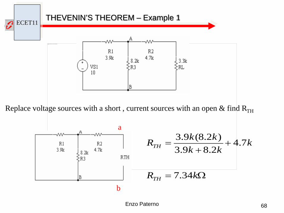
Replace voltage sources with a short , current sources with an open & find RTH
a
b Ω=
++
=
kR
kkk
kkR
TH
TH
34.7
7.42.89.3
)2.8(9.3
THEVENIN’S THEOREM – Example 1
ECET11
69 Enzo Paterno
This image cannot currently be displayed.
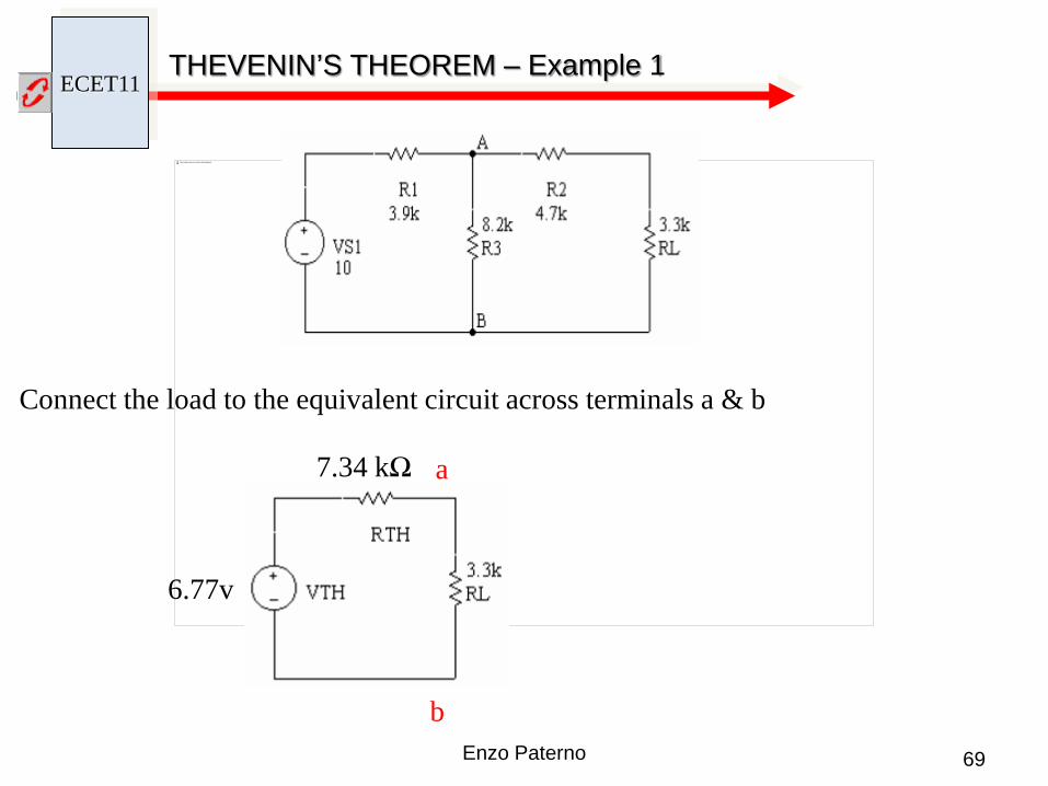
Connect the load to the equivalent circuit across terminals a & b
a
b
6.77v
7.34 kΩ
THEVENIN’S THEOREM – Example 1

ECET11
70 Enzo Paterno
This image cannot currently be displayed. a
6.77v
7.34 kΩ
vV
kkkV
RL
RL
10.2
3.334.7)3.3(77.6
=
+=
b
THEVENIN’S THEOREM – Example 1

ECET11
71 Enzo Paterno
This image cannot currently be displayed. a
6.77v
7.34 kΩ
uAI
kkI
RL
RL
27.636
3.334.777.6
=
+=
b
THEVENIN’S THEOREM – Example 1

ECET11
72 Enzo Paterno
This image cannot currently be displayed.
THEVENIN’S THEOREM – Example 2
vkmAV
mAIkkkmAI
TH
R
R
18)3(6
627
)2(27
1
3
3
==
=+
=

ECET11
73 Enzo Paterno
This image cannot currently be displayed.
THEVENIN’S THEOREM – Example 2
vVVVvV
kkkkV
THTHTH
TH
TH
268180.8
432)3(24
21
2
2
=+=+==
++=

ECET11
74 Enzo Paterno
THEVENIN’S THEOREM
This image cannot currently be displayed.
Ω=
++
=
kR
kkk
kkR
TH
TH
3
136
)3(6

ECET11
75 Enzo Paterno
THEVENIN’S THEOREM
This image cannot currently be displayed.
26v
3kΩ
ECET11
76 Enzo Paterno
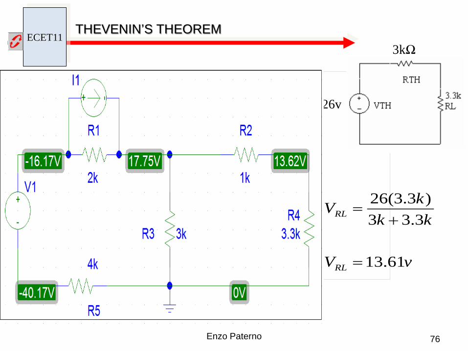
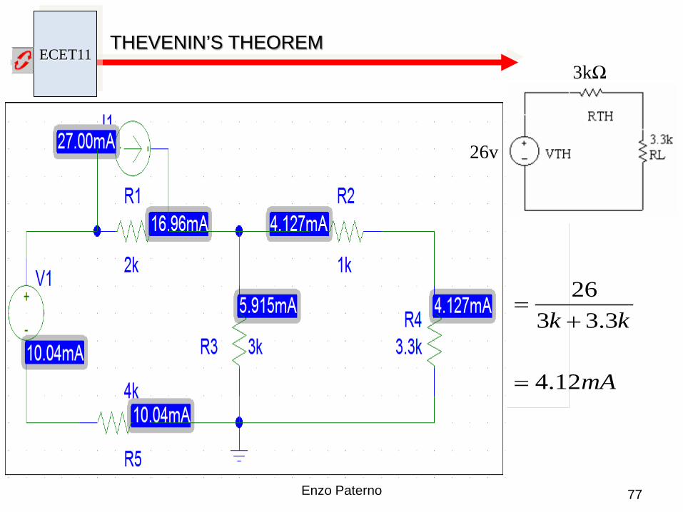
THEVENIN’S THEOREM
This image cannot currently be displayed.
26v
3kΩ
vV
kkkV
RL
RL
61.13
3.33)3.3(26
=
+=
ECET11
77 Enzo Paterno
THEVENIN’S THEOREM
This image cannot currently be displayed.
mAI
kkI
RL
RL
12.4
3.3326
=
+=
26v
3kΩ

ECET11 RC CIRCUIT – THEVENIN EQUIVALENT
78 Enzo Paterno
ECET11
79 Enzo Paterno
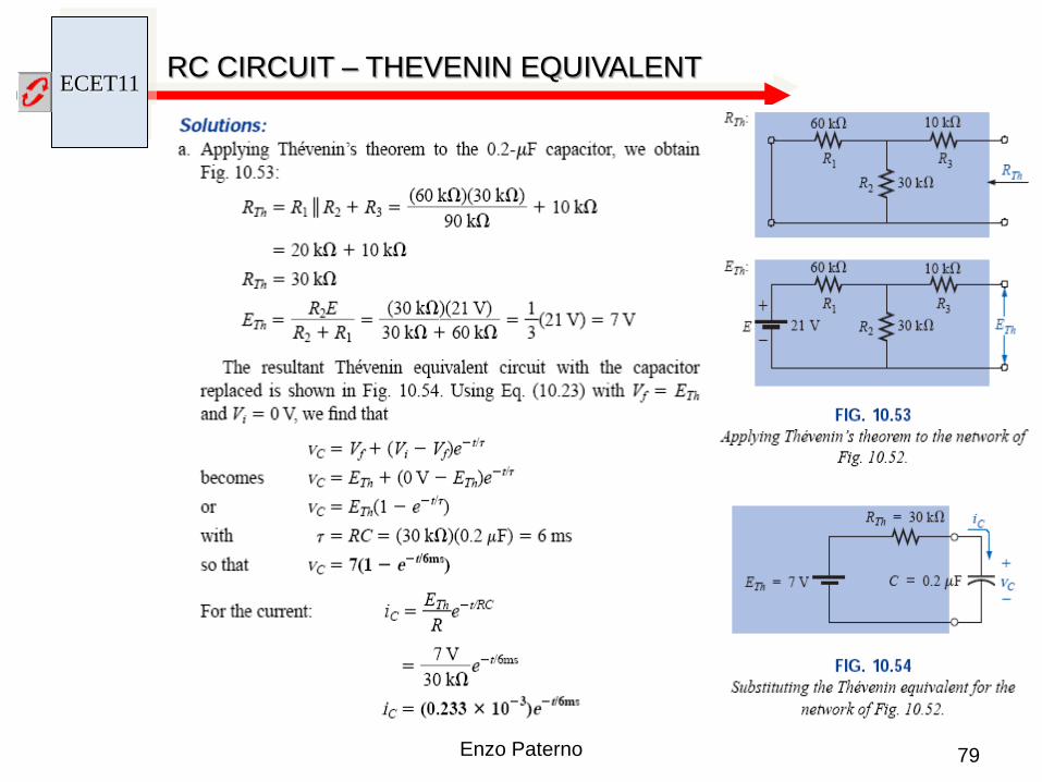
RC CIRCUIT – THEVENIN EQUIVALENT
ECET11
80 Enzo Paterno
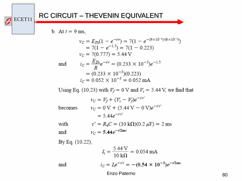
RC CIRCUIT – THEVENIN EQUIVALENT

ECET11
81 Enzo Paterno
RC CIRCUIT – THEVENIN EQUIVALENT

ECET11
82 Enzo Paterno
FORMULAS
Charging Phase: @ vC (0) = Vi
)()( tVtVE CR +=
the voltage across a capacitor cannot change instantaneously
Discharging Phase:
dVE =Ɛ
VQC =
dAC orεε=
dtvCi
∆∆
=∆
)(21)( 2 tCvtwC =
)()()( tvtitp =
= ∑
=
n
I iS CC 1
11
= ∑
=
N
iiP CC
1
Charging Phase: @ vC (0) = 0
RCt
R EetV−
=)(
RCt
eREtCI
−
=)(
−=
−RC
t
C eEtV 1)(
RC=τ
( ) RCt
iR eVEtV−
−=)(
( ) RCt
iC eVEEtV−
−−=)(
( ) RCt
iC eEVEtV−
−+=)(
RCt
i eR
VEtCI−−
=)(
@ Steady State C is an open circuit
RCt
C EetV−
=)(
RCt
R EetV−
=)(
RCt
c eREtI
−=)(
Steady State: t ∞ = 5τ