Embed Size (px)
Citation preview
Journal of Network and Computer Applications 36 (2013) 1164–1173
Contents lists available at SciVerse ScienceDirect
Journal of Network and Computer Applications
1084-80
http://d
n Corr
E-m
cllin@cs
gingliu.
journal homepage: www.elsevier.com/locate/jnca
Can: A context-aware NAT traversal scheme
Chien-Chao Tseng a, Chia-Liang Lin a,n, Li-Hsing Yen b, Jyun-Yan Liu a, Cheng-Yuan Ho c
a Department of Computer Science, National Chiao Tung University No. 1001 University Road, Hsinchu 300, Taiwan, ROCb Department of Computer Science and Information Engineering, National University of Kaohsiung No.700, Kaohsiung University Road, Nan Tzu District,
Kaohsiung 811, Taiwan, ROCc Advanced Research Center, Institute for Information Industry 1F., No.133, Sec. 4, Minsheng E. Road, Songshan District, Taipei City 105, Taiwan, ROC
a r t i c l e i n f o
Article history:
Received 18 July 2012
Received in revised form
10 December 2012
Accepted 1 February 2013Available online 17 February 2013
Keywords:
CAN
ICE
NAT
NAT traversal
STUN
TURN
45/$ - see front matter & 2013 Elsevier Ltd. A
x.doi.org/10.1016/j.jnca.2013.02.001
esponding author. Tel.: þ886 3 57121 21x54
ail addresses: [email protected] (C.-C. T
.nctu.edu.tw (C.-L. Lin), [email protected] (L
[email protected] (J.-Y. Liu), [email protected]
a b s t r a c t
Network Address Translation (NAT) is a technique commonly used to share one public IPv4 address
among several hosts located behind a NAT device. NAT devices typically block session requests
originating from outside, causing NAT traversal problem that prevents the establishment of peer-to-
peer (P2P) sessions. There have been many proposals for the NAT traversal problem. However, existing
methods induce high connectivity check delay and resource demand when finding a communicating
path, calling for a routine that determines the path best suited for a given pair of communicating peers.
This study proposes CAN, a Context-Aware NAT traversal scheme which gathers and exchanges
network-context information to find the most appropriate path for two communicating peers behind
NAT devices. We have implemented CAN and conducted extensive experiments with off-the-shelf NAT
devices to compare the performance of CAN with Interactivity Connectivity Establishment (ICE), the
most acknowledged approach to creating a session across NATs. Experimental results show that CAN
outperforms ICE in terms of direct communication ratio, connectivity check delay and message
overload when checking connectivity.
& 2013 Elsevier Ltd. All rights reserved.
1. Introduction
Peer-to-peer (P2P) communication has emerged as the main-stream of network applications and has gained immense popu-larity in recent years. P2P communication can not only avoid theexpense but also shorten the delay of handling traffic at a server.Voice over internet protocol (VoIP) is one of the most popular P2Papplications. However, this style of communication often hasproblems dealing with Network Address Translation (NAT)(Francis and Egevang, 2001; Stegel et al., 2010; Lin et al., 2010).
NAT is a solution to alleviate the exhaustion of IPv4 address. Bymodifying network address information stored in packet headerwhen packets pass through a traffic routing device, NAT remaps agiven address realm into another, while also providing transparentrouting for the hosts behind a NAT. The nature of NAT causes NATtraversal problem (Lin et al., 2010; Aurel Constantinescu et al., 2005;Ho et al., 2011), which is a barrier to P2P applications. Not until aninternal host (IH) behind a NAT device sends a packet to an externalhost (EH) outside the NAT first can the EH send packets to the IHdirectly. In other words, NAT device blocks session requests origi-nating from the external side, which prevents the establishment of
ll rights reserved.
792; fax: þ886 3 5721 490.
seng),
.-H. Yen),
du.tw (C.-Y. Ho).
P2P sessions. The situation becomes worse when both hosts arebehind different NAT devices. As a remedy, many NAT traversaltechniques (Yoshimi et al., 2007; Saikat et al., 2004; Rosenberg et al.,2008, 2010; Rosenberg, 2010; Boucadair et al., 2011; Mao et al.,2012; Cuevas et al., 2010; Chen and Jia, 2009; Patro et al., 2011;Houngue et al., 2011) have been proposed to establish and maintainTCP/IP network sessions across NAT devices. NAT traversal isindispensable for P2P applications running in NAT environment.
Many existing NAT traversal methods rely on a server withpublicly routable IP addresses. Some methods only use the serverwhen establishing a session (such as STUN, Rosenberg et al., 2008;Maenpaa et al., 2010; Bae and Cho, 2010). Some relay all datathrough the server (such as TURN, Rosenberg et al., 2010;Houngue et al., 2011; Maenpaa et al., 2010; Bae and Cho, 2010,MOSAIC, Mao et al., 2012, GPA, Cuevas et al., 2010), but theseapproaches increase both bandwidth costs and latency. Theserelaying methods are also detrimental to real-time voice andvideo communication. Some NAT traversal methods do not need aserver (such as UPnP, Boucadair et al., 2011; Patro et al., 2011,NATng, Chen and Jia, 2009), but these approaches require mod-ifications on NAT devices. The Internet Engineering Task Force(IETF) proposed Interactive Connectivity Establishment (ICE)(Rosenberg, 2010; Maenpaa et al., 2010) to provide NAT traversalcapabilities for session-oriented protocol. ICE makes use of STUNand TURN and provides a unified framework around them. ICEhosts exchange accessibility information and negotiate with each
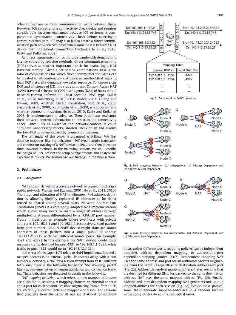
Fig. 1. An example of NAPT operation.
Node A
Node B
Node C
Node A
Node B
Node C
Node A
Node B
Node C
NAT NAT
NAT
C.-C. Tseng et al. / Journal of Network and Computer Applications 36 (2013) 1164–1173 1165
other to find one or more communication paths between them.However, ICE causes a long connectivity check delay and requiresconsiderable message exchanges because ICE performs a com-plete and systematical connectivity check before selecting acommunication path. ICE may also fail to create a direct commu-nication path between two hosts when some host is behind a NATdevice that implements connection tracking (Ho et al., 2010;Raste and Kulkarni, 2008).
As direct communication paths save bandwidth demand andlatency caused by relaying methods, direct communication ratio(DCR) serves as another important metric for evaluating a NATtraversal method. Given a set of NAT combinations, DCR is theratio of combinations for which direct communication paths canbe created to all combinations. A traversal method that leads tohigh DCR naturally demands low relay resource. To improve theDCR and efficiency of ICE, this study proposes Context Aware NAT(CAN) traversal scheme. In CAN, user agents (UAs) of hosts obtainnetwork-context information (host location, NAT type, Saikatet al., 2004; Rosenberg et al., 2003; Audet, 2007; Huang andHwang, 2009, whether hairpin translation, Ford et al., 2005;Srisuresh et al., 2008; Kuramochi et al., 2008, is supported andwhether connection tracking, Ho et al., 2010; Raste and Kulkarni,2008, is implemented) in advance. Then both hosts exchangetheir network-context information to assist in the connectivitycheck. Since CAN is aware of the network-context, it couldeliminate unnecessary checks, shorten check delay and resolvethe low-DCR problem caused by connection tracking.
The remainder of this paper is organized as follows. We firstdescribe mapping, filtering behaviors, NAT type, hairpin translationand connection tracking of a NAT device in detail, and then introducethree traversal methods. In the following sections, we will describethe design of CAN, present the setup of experiments and analyze theexperiment results. We summarize our findings in the final section.
Fig. 2. NAT mapping behavior. (a) Independent; (b) Address Dependent and
(c) Address & Port Dependent.
Node A
Node B
Node C
NAT Node A
Node B
Node C
NAT
Node A
Node B
Node C
NAT
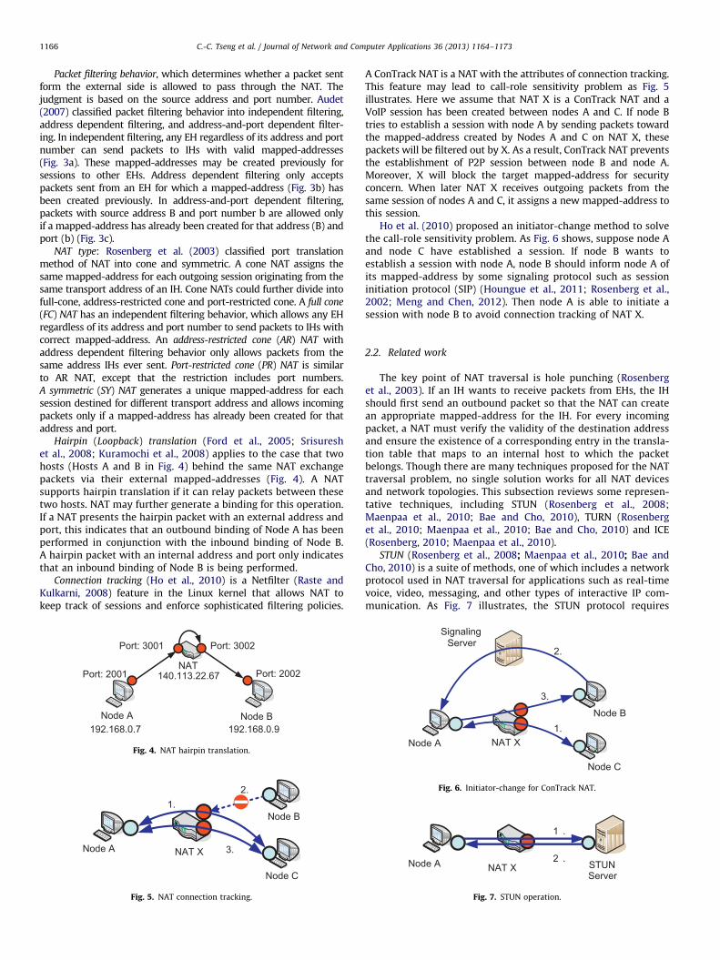
Fig. 3. NAT filtering behavior. (a) Independent; (b) Address Dependent and
(c) Address & Port Dependent.
2. Preliminary
2.1. Background
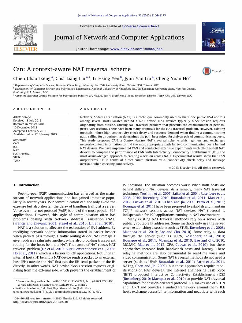
NAT allows IHs within a private network to connect to EHs in apublic network (Francis and Egevang, 2001; Ho et al., 2011, 2010).The usage and toleration of NAT ameliorates IPv4 address deple-tion by allowing globally registered IP addresses to be eitherreused or shared among several hosts. Network Address PortTranslation (NAPT) is a commonly adopted NAT implementation,which allows many hosts to share a single IP address throughmultiplexing streams differentiated by a TCP/UDP port number.Figure 1 illustrates an example where two hosts with privateaddresses 192.168.1.1 and 192.168.1.2, respectively, send packetsfrom port number 1234. A NAPT device might translate sourceaddresses of these packets into a single public IP address140.113.215.215 with two different source ports (for example,4321 and 4322). In this example, the NAPT device would routeresponse traffic destined for port 4321 to 192.168.1.1:1234, whiletraffic to port 4322 would go to 192.168.1.2:1234.
In the rest of this paper, NAT refers to NAPT implementation, and amapped-address is an external global IP address along with a portnumber allocated by a NAT for a session attempt from an IH. DifferentNATs may differ in the following behaviors: NAT mapping, packetfiltering, implementation of hairpin translation and connection track-ing. These behaviors are discussed in details in the following.
NAT mapping behavior, which refers to how mapped-addressesare allocated to sessions. A mapping chooses an external addressand a port for each session. Sessions originating from different IHsare certainly allocated different mapped-addresses. For sessionsthat originate from the same IH but are destined for different
hosts and/or different ports, mapping policies can be independentmapping, address dependent mapping, or address-and-portdependent mapping (Audet, 2007). Independent mapping NATuses the same address and port for all outbound packets originat-ing from the same IH regardless of destination address and port(Fig. 2a). Address dependent mapping differentiates sessions thatare destined for different EHs. For packets to the same destinationaddress, NAT uses the same mapped-address (Fig. 2b). Finally,address-and-port dependent mapping NAT generates one uniquemapped-address for each session (Fig. 2c). Beside these polices,some NATs generate mapped-addresses in a random fashionwhile some others do so in a sequential order.
C.-C. Tseng et al. / Journal of Network and Computer Applications 36 (2013) 1164–11731166
Packet filtering behavior, which determines whether a packet sentform the external side is allowed to pass through the NAT. Thejudgment is based on the source address and port number. Audet(2007) classified packet filtering behavior into independent filtering,address dependent filtering, and address-and-port dependent filter-ing. In independent filtering, any EH regardless of its address and portnumber can send packets to IHs with valid mapped-addresses(Fig. 3a). These mapped-addresses may be created previously forsessions to other EHs. Address dependent filtering only acceptspackets sent from an EH for which a mapped-address (Fig. 3b) hasbeen created previously. In address-and-port dependent filtering,packets with source address B and port number b are allowed onlyif a mapped-address has already been created for that address (B) andport (b) (Fig. 3c).
NAT type: Rosenberg et al. (2003) classified port translationmethod of NAT into cone and symmetric. A cone NAT assigns thesame mapped-address for each outgoing session originating from thesame transport address of an IH. Cone NATs could further divide intofull-cone, address-restricted cone and port-restricted cone. A full cone
(FC) NAT has an independent filtering behavior, which allows any EHregardless of its address and port number to send packets to IHs withcorrect mapped-address. An address-restricted cone (AR) NAT withaddress dependent filtering behavior only allows packets from thesame address IHs ever sent. Port-restricted cone (PR) NAT is similarto AR NAT, except that the restriction includes port numbers.A symmetric (SY) NAT generates a unique mapped-address for eachsession destined for different transport address and allows incomingpackets only if a mapped-address has already been created for thataddress and port.
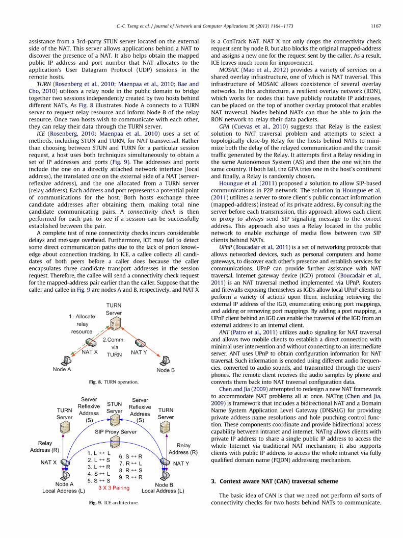
Hairpin (Loopback) translation (Ford et al., 2005; Srisureshet al., 2008; Kuramochi et al., 2008) applies to the case that twohosts (Hosts A and B in Fig. 4) behind the same NAT exchangepackets via their external mapped-addresses (Fig. 4). A NATsupports hairpin translation if it can relay packets between thesetwo hosts. NAT may further generate a binding for this operation.If a NAT presents the hairpin packet with an external address andport, this indicates that an outbound binding of Node A has beenperformed in conjunction with the inbound binding of Node B.A hairpin packet with an internal address and port only indicatesthat an inbound binding of Node B is being performed.
Connection tracking (Ho et al., 2010) is a Netfilter (Raste andKulkarni, 2008) feature in the Linux kernel that allows NAT tokeep track of sessions and enforce sophisticated filtering policies.
Node A Node B192.168.0.7 192.168.0.9
NAT140.113.22.67
Port: 3001
Port: 2001 Port: 2002
Port: 3002
Fig. 4. NAT hairpin translation.
Node B
Node A NAT X
Node C
1.2.
3.
Fig. 5. NAT connection tracking.
A ConTrack NAT is a NAT with the attributes of connection tracking.This feature may lead to call-role sensitivity problem as Fig. 5illustrates. Here we assume that NAT X is a ConTrack NAT and aVoIP session has been created between nodes A and C. If node Btries to establish a session with node A by sending packets towardthe mapped-address created by Nodes A and C on NAT X, thesepackets will be filtered out by X. As a result, ConTrack NAT preventsthe establishment of P2P session between node B and node A.Moreover, X will block the target mapped-address for securityconcern. When later NAT X receives outgoing packets from thesame session of nodes A and C, it assigns a new mapped-address tothis session.
Ho et al. (2010) proposed an initiator-change method to solvethe call-role sensitivity problem. As Fig. 6 shows, suppose node Aand node C have established a session. If node B wants toestablish a session with node A, node B should inform node A ofits mapped-address by some signaling protocol such as sessioninitiation protocol (SIP) (Houngue et al., 2011; Rosenberg et al.,2002; Meng and Chen, 2012). Then node A is able to initiate asession with node B to avoid connection tracking of NAT X.
2.2. Related work
The key point of NAT traversal is hole punching (Rosenberget al., 2003). If an IH wants to receive packets from EHs, the IHshould first send an outbound packet so that the NAT can createan appropriate mapped-address for the IH. For every incomingpacket, a NAT must verify the validity of the destination addressand ensure the existence of a corresponding entry in the transla-tion table that maps to an internal host to which the packetbelongs. Though there are many techniques proposed for the NATtraversal problem, no single solution works for all NAT devicesand network topologies. This subsection reviews some represen-tative techniques, including STUN (Rosenberg et al., 2008;Maenpaa et al., 2010; Bae and Cho, 2010), TURN (Rosenberget al., 2010; Maenpaa et al., 2010; Bae and Cho, 2010) and ICE(Rosenberg, 2010; Maenpaa et al., 2010).
STUN (Rosenberg et al., 2008; Maenpaa et al., 2010; Bae andCho, 2010) is a suite of methods, one of which includes a networkprotocol used in NAT traversal for applications such as real-timevoice, video, messaging, and other types of interactive IP com-munication. As Fig. 7 illustrates, the STUN protocol requires
Node A NAT X
Node C
Node B1.
2.
3.
SignalingServer
Fig. 6. Initiator-change for ConTrack NAT.
Node A NAT X
1 .
2 . STUNServer
Fig. 7. STUN operation.
C.-C. Tseng et al. / Journal of Network and Computer Applications 36 (2013) 1164–1173 1167
assistance from a 3rd-party STUN server located on the externalside of the NAT. This server allows applications behind a NAT todiscover the presence of a NAT. It also helps obtain the mappedpublic IP address and port number that NAT allocates to theapplication’s User Datagram Protocol (UDP) sessions in theremote hosts.
TURN (Rosenberg et al., 2010; Maenpaa et al., 2010; Bae andCho, 2010) utilizes a relay node in the public domain to bridgetogether two sessions independently created by two hosts behinddifferent NATs. As Fig. 8 illustrates, Node A connects to a TURNserver to request relay resource and inform Node B of the relayresource. Once two hosts wish to communicate with each other,they can relay their data through the TURN server.
ICE (Rosenberg, 2010; Maenpaa et al., 2010) uses a set ofmethods, including STUN and TURN, for NAT transversal. Ratherthan choosing between STUN and TURN for a particular sessionrequest, a host uses both techniques simultaneously to obtain aset of IP addresses and ports (Fig. 9). The addresses and portsinclude the one on a directly attached network interface (localaddress), the translated one on the external side of a NAT (server-reflexive address), and the one allocated from a TURN server(relay address). Each address and port represents a potential pointof communications for the host. Both hosts exchange threecandidate addresses after obtaining them, making total ninecandidate communicating pairs. A connectivity check is thenperformed for each pair to see if a session can be successfullyestablished between the pair.
A complete test of nine connectivity checks incurs considerabledelays and message overhead. Furthermore, ICE may fail to detectsome direct communication paths due to the lack of priori knowl-edge about connection tracking. In ICE, a callee collects all candi-dates of both peers before a caller does because the callerencapsulates three candidate transport addresses in the sessionrequest. Therefore, the callee will send a connectivity check requestfor the mapped-address pair earlier than the caller. Suppose that thecaller and callee in Fig. 9 are nodes A and B, respectively, and NAT X
NAT X NAT Y
Node BNode A
1. Allocaterelay
resource2.Comm.
viaTURN
TURNServer
Fig. 8. TURN operation.
ServerReflexiveAddress
ServerReflexiveAddress
(S) (S)
3 X 3 Pairing
1. L L2. L S3. L R4. S L5. S S
6. S R7. R L8. R S9. R R
TURNServer
TURNServer
NAT X NAT Y
RelayAddress (R)
RelayAddress (R)
SIP Proxy Server
STUNServer
Node A Node BLocal Address (L) Local Address (L)
↔↔↔↔↔
↔↔↔↔
Fig. 9. ICE architecture.
is a ConTrack NAT. NAT X not only drops the connectivity checkrequest sent by node B, but also blocks the original mapped-addressand assigns a new one for the request sent by the caller. As a result,ICE leaves much room for improvement.
MOSAIC (Mao et al., 2012) provides a variety of services on ashared overlay infrastructure, one of which is NAT traversal. Thisinfrastructure of MOSAIC allows coexistence of several overlaynetworks. In this architecture, a resilient overlay network (RON),which works for nodes that have publicly routable IP addresses,can be placed on the top of another overlay protocol that enablesNAT traversal. Nodes behind NATs can thus be able to join theRON network to relay their data packets.
GPA (Cuevas et al., 2010) suggests that Relay is the easiestsolution to NAT traversal problem and attempts to select atopologically close-by Relay for the hosts behind NATs to mini-mize both the delay of the relayed communication and the transittraffic generated by the Relay. It attempts first a Relay residing inthe same Autonomous System (AS) and then the one within thesame country. If both fail, the GPA tries one in the host’s continentand finally, a Relay is randomly chosen.
Houngue et al. (2011) proposed a solution to allow SIP-basedcommunications in P2P network. The solution in Houngue et al.(2011) utilizes a server to store client’s public contact information(mapped-address) instead of its private address. By consulting theserver before each transmission, this approach allows each clientor proxy to always send SIP signaling message to the correctaddress. This approach also uses a Relay located in the publicnetwork to enable exchange of media flow between two SIPclients behind NATs.
UPnP (Boucadair et al., 2011) is a set of networking protocols thatallows networked devices, such as personal computers and homegateways, to discover each other’s presence and establish services forcommunications. UPnP can provide further assistance with NATtraversal. Internet gateway device (IGD) protocol (Boucadair et al.,2011) is an NAT traversal method implemented via UPnP. Routersand firewalls exposing themselves as IGDs allow local UPnP clients toperform a variety of actions upon them, including retrieving theexternal IP address of the IGD, enumerating existing port mappings,and adding or removing port mappings. By adding a port mapping, aUPnP client behind an IGD can enable the traversal of the IGD from anexternal address to an internal client.
ANT (Patro et al., 2011) utilizes audio signaling for NAT traversaland allows two mobile clients to establish a direct connection withminimal user intervention and without connecting to an intermediateserver. ANT uses UPnP to obtain configuration information for NATtraversal. Such information is encoded using different audio frequen-cies, converted to audio sounds, and transmitted through the users’phones. The remote client receives the audio samples by phone andconverts them back into NAT traversal configuration data.
Chen and Jia (2009) attempted to redesign a new NAT frameworkto accommodate NAT problems all at once. NATng (Chen and Jia,2009) is framework that includes a bidirectional NAT and a DomainName System Application Level Gateway (DNSALG) for providingprivate address name resolutions and hole punching control func-tion. These components coordinate and provide bidirectional accesscapability between intranet and internet. NATng allows clients withprivate IP address to share a single public IP address to access thewhole Internet via traditional NAT mechanism; it also supportsclients with public IP address to access the whole intranet via fullyqualified domain name (FQDN) addressing mechanism.
3. Context aware NAT (CAN) traversal scheme
The basic idea of CAN is that we need not perform all sorts ofconnectivity checks for two hosts behind NATs to communicate.
Caller CalleeNATX NAT YSTUN Server STUN ServerSIP Proxy
3 .
1 .
2 .
4 .
CAN Connectivity Check
RTP Data
NAT Info. collectionNAT Info. collection
Invite (NAT X info.) Invite (NAT X info.)
200 OK (NAT Y info.) 200 OK (NAT Y info.)
Fig. 10. CAN operation with SIP-based VoIP.
YesYes
NoNo
Yes
BothunderNAT
IdenticalNAT IP
IdenticalNAT Info.
Both Under NATs
Case 1(Public Domain)
Case 4(DifferentNAT)
Case 3Case 2
Start
No
C.-C. Tseng et al. / Journal of Network and Computer Applications 36 (2013) 1164–11731168
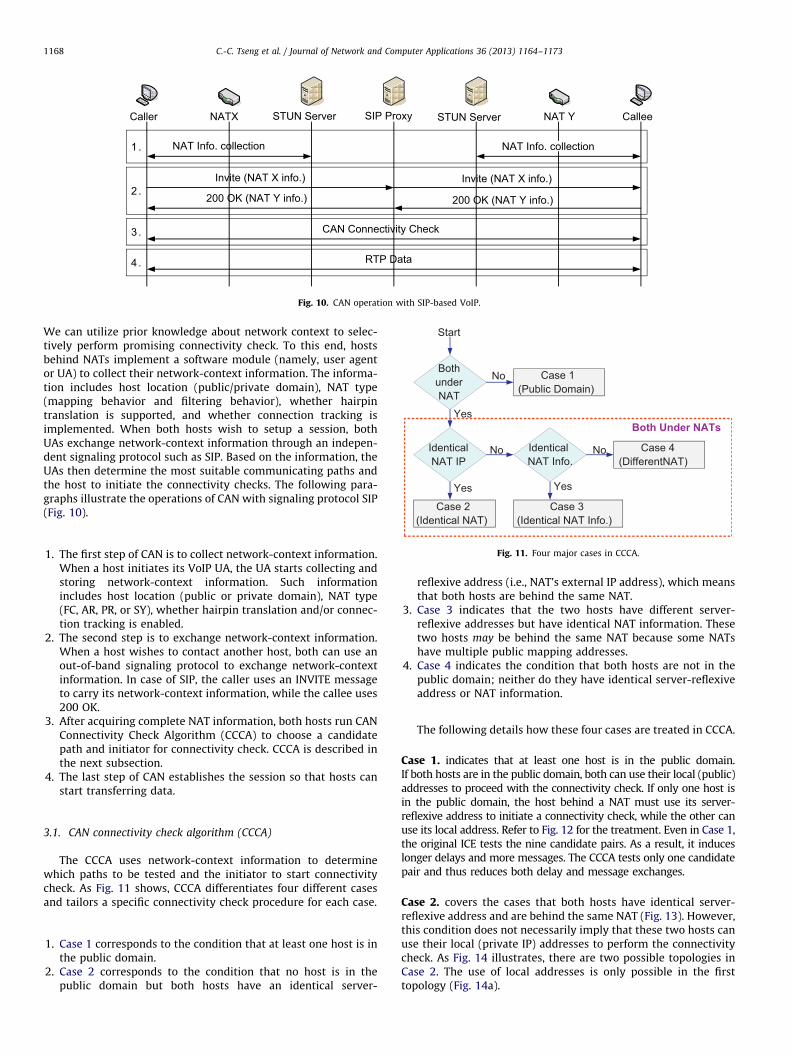
We can utilize prior knowledge about network context to selec-tively perform promising connectivity check. To this end, hostsbehind NATs implement a software module (namely, user agentor UA) to collect their network-context information. The informa-tion includes host location (public/private domain), NAT type(mapping behavior and filtering behavior), whether hairpintranslation is supported, and whether connection tracking isimplemented. When both hosts wish to setup a session, bothUAs exchange network-context information through an indepen-dent signaling protocol such as SIP. Based on the information, theUAs then determine the most suitable communicating paths andthe host to initiate the connectivity checks. The following para-graphs illustrate the operations of CAN with signaling protocol SIP(Fig. 10).
(Identical NAT Info.)(Identical NAT)
Fig. 11. Four major cases in CCCA.
1. The first step of CAN is to collect network-context information.When a host initiates its VoIP UA, the UA starts collecting andstoring network-context information. Such informationincludes host location (public or private domain), NAT type(FC, AR, PR, or SY), whether hairpin translation and/or connec-tion tracking is enabled.2.
The second step is to exchange network-context information.When a host wishes to contact another host, both can use anout-of-band signaling protocol to exchange network-contextinformation. In case of SIP, the caller uses an INVITE messageto carry its network-context information, while the callee uses200 OK.3.
After acquiring complete NAT information, both hosts run CANConnectivity Check Algorithm (CCCA) to choose a candidatepath and initiator for connectivity check. CCCA is described inthe next subsection.4.
The last step of CAN establishes the session so that hosts canstart transferring data.3.1. CAN connectivity check algorithm (CCCA)
The CCCA uses network-context information to determinewhich paths to be tested and the initiator to start connectivitycheck. As Fig. 11 shows, CCCA differentiates four different casesand tailors a specific connectivity check procedure for each case.
1.
Case 1 corresponds to the condition that at least one host is inthe public domain.2.
Case 2 corresponds to the condition that no host is in thepublic domain but both hosts have an identical server-reflexive address (i.e., NAT’s external IP address), which meansthat both hosts are behind the same NAT.
3.
Case 3 indicates that the two hosts have different server-reflexive addresses but have identical NAT information. Thesetwo hosts may be behind the same NAT because some NATshave multiple public mapping addresses.4.
Case 4 indicates the condition that both hosts are not in thepublic domain; neither do they have identical server-reflexiveaddress or NAT information.The following details how these four cases are treated in CCCA.
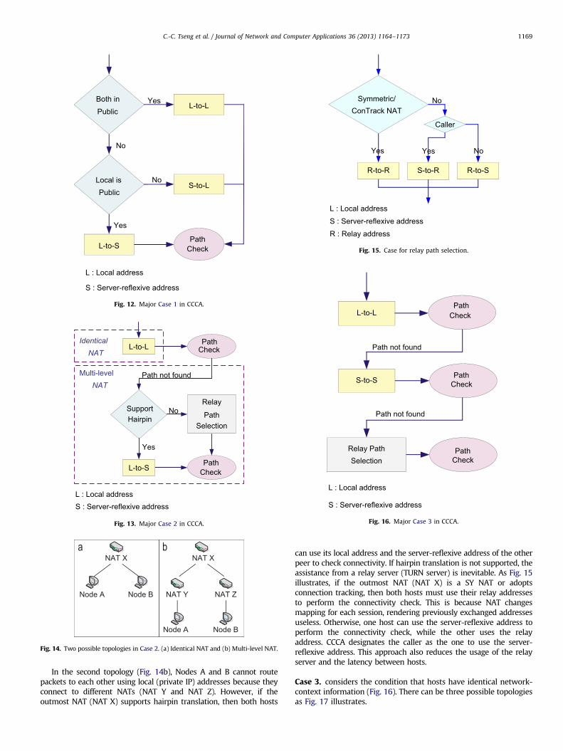
Case 1. indicates that at least one host is in the public domain.If both hosts are in the public domain, both can use their local (public)addresses to proceed with the connectivity check. If only one host isin the public domain, the host behind a NAT must use its server-reflexive address to initiate a connectivity check, while the other canuse its local address. Refer to Fig. 12 for the treatment. Even in Case 1,the original ICE tests the nine candidate pairs. As a result, it induceslonger delays and more messages. The CCCA tests only one candidatepair and thus reduces both delay and message exchanges.
Case 2. covers the cases that both hosts have identical server-reflexive address and are behind the same NAT (Fig. 13). However,this condition does not necessarily imply that these two hosts canuse their local (private IP) addresses to perform the connectivitycheck. As Fig. 14 illustrates, there are two possible topologies inCase 2. The use of local addresses is only possible in the firsttopology (Fig. 14a).
No
Caller
Symmetric/ConTrack NAT
S-to-R R-to-SR-to-R
Yes Yes No
L : Local address
S : Server-reflexive address
R : Relay address
Fig. 15. Case for relay path selection.
No
No
Yes
YesBoth inPublic
Local isPublic
PathCheck
L-to-L
L-to-S
S-to-L
L : Local address
S : Server-reflexive address
Fig. 12. Major Case 1 in CCCA.
No
Path not found
IdenticalNAT
SupportHairpin
PathCheckL-to-L
L-to-S
Relay
PathSelection
Multi-levelNAT
Yes
L : Local addressS : Server-reflexive address
PathCheck
Fig. 13. Major Case 2 in CCCA.
NAT Y NAT Z
NAT X NAT X
Node A
Node A
Node B
Node B
Fig. 14. Two possible topologies in Case 2. (a) Identical NAT and (b) Multi-level NAT.
Path not found
Path not found
PathCheck
S-to-S
L-to-L
Relay PathSelection
L : Local address
S : Server-reflexive address
PathCheck
PathCheck
Fig. 16. Major Case 3 in CCCA.
C.-C. Tseng et al. / Journal of Network and Computer Applications 36 (2013) 1164–1173 1169
In the second topology (Fig. 14b), Nodes A and B cannot routepackets to each other using local (private IP) addresses because theyconnect to different NATs (NAT Y and NAT Z). However, if theoutmost NAT (NAT X) supports hairpin translation, then both hosts
can use its local address and the server-reflexive address of the otherpeer to check connectivity. If hairpin translation is not supported, theassistance from a relay server (TURN server) is inevitable. As Fig. 15illustrates, if the outmost NAT (NAT X) is a SY NAT or adoptsconnection tracking, then both hosts must use their relay addressesto perform the connectivity check. This is because NAT changesmapping for each session, rendering previously exchanged addressesuseless. Otherwise, one host can use the server-reflexive address toperform the connectivity check, while the other uses the relayaddress. CCCA designates the caller as the one to use the server-reflexive address. This approach also reduces the usage of the relayserver and the latency between hosts.
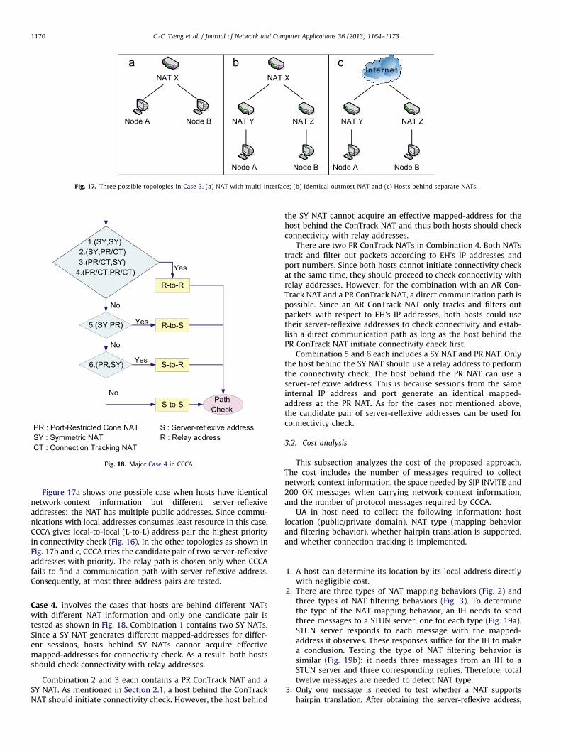
Case 3. considers the condition that hosts have identical network-context information (Fig. 16). There can be three possible topologiesas Fig. 17 illustrates.
NAT Y NAT Z NAT Y NAT Z
NAT X NAT X
Node A Node B
Node A Node BNode A Node B
In te rn e t
Fig. 17. Three possible topologies in Case 3. (a) NAT with multi-interface; (b) Identical outmost NAT and (c) Hosts behind separate NATs.
No
No
Yes
Yes
Yes
No
5.(SY,PR)
PathCheck
1.(SY,SY)2.(SY,PR/CT)3.(PR/CT,SY)
4.(PR/CT,PR/CT)
R-to-S
S-to-R
R-to-R
6.(PR,SY)
PR : Port-Restricted Cone NATSY : Symmetric NATCT : Connection Tracking NAT
S : Server-reflexive addressR : Relay address
S-to-S
Fig. 18. Major Case 4 in CCCA.
C.-C. Tseng et al. / Journal of Network and Computer Applications 36 (2013) 1164–11731170
Figure 17a shows one possible case when hosts have identicalnetwork-context information but different server-reflexiveaddresses: the NAT has multiple public addresses. Since commu-nications with local addresses consumes least resource in this case,CCCA gives local-to-local (L-to-L) address pair the highest priorityin connectivity check (Fig. 16). In the other topologies as shown inFig. 17b and c, CCCA tries the candidate pair of two server-reflexiveaddresses with priority. The relay path is chosen only when CCCAfails to find a communication path with server-reflexive address.Consequently, at most three address pairs are tested.
Case 4. involves the cases that hosts are behind different NATswith different NAT information and only one candidate pair istested as shown in Fig. 18. Combination 1 contains two SY NATs.Since a SY NAT generates different mapped-addresses for differ-ent sessions, hosts behind SY NATs cannot acquire effectivemapped-addresses for connectivity check. As a result, both hostsshould check connectivity with relay addresses.
Combination 2 and 3 each contains a PR ConTrack NAT and aSY NAT. As mentioned in Section 2.1, a host behind the ConTrackNAT should initiate connectivity check. However, the host behind
the SY NAT cannot acquire an effective mapped-address for thehost behind the ConTrack NAT and thus both hosts should checkconnectivity with relay addresses.
There are two PR ConTrack NATs in Combination 4. Both NATstrack and filter out packets according to EH’s IP addresses andport numbers. Since both hosts cannot initiate connectivity checkat the same time, they should proceed to check connectivity withrelay addresses. However, for the combination with an AR Con-Track NAT and a PR ConTrack NAT, a direct communication path ispossible. Since an AR ConTrack NAT only tracks and filters outpackets with respect to EH’s IP addresses, both hosts could usetheir server-reflexive addresses to check connectivity and estab-lish a direct communication path as long as the host behind thePR ConTrack NAT initiate connectivity check first.
Combination 5 and 6 each includes a SY NAT and PR NAT. Onlythe host behind the SY NAT should use a relay address to performthe connectivity check. The host behind the PR NAT can use aserver-reflexive address. This is because sessions from the sameinternal IP address and port generate an identical mapped-address at the PR NAT. As for the cases not mentioned above,the candidate pair of server-reflexive addresses can be used forconnectivity check.
3.2. Cost analysis
This subsection analyzes the cost of the proposed approach.The cost includes the number of messages required to collectnetwork-context information, the space needed by SIP INVITE and200 OK messages when carrying network-context information,and the number of protocol messages required by CCCA.
UA in host need to collect the following information: hostlocation (public/private domain), NAT type (mapping behaviorand filtering behavior), whether hairpin translation is supported,and whether connection tracking is implemented.
1.
A host can determine its location by its local address directlywith negligible cost.2.
There are three types of NAT mapping behaviors (Fig. 2) andthree types of NAT filtering behaviors (Fig. 3). To determinethe type of the NAT mapping behavior, an IH needs to sendthree messages to a STUN server, one for each type (Fig. 19a).STUN server responds to each message with the mapped-address it observes. These responses suffice for the IH to makea conclusion. Testing the type of NAT filtering behavior issimilar (Fig. 19b): it needs three messages from an IH to aSTUN server and three corresponding replies. Therefore, totaltwelve messages are needed to detect NAT type.3.
Only one message is needed to test whether a NAT supportshairpin translation. After obtaining the server-reflexive address,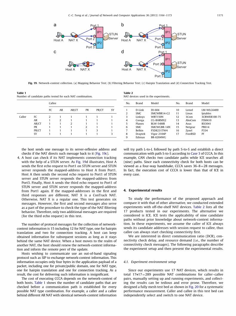
Host A NAT X
STUNServer
IP1
IP2Host A NAT X
STUNServer
IP1
IP2
Host A NAT X
IP1
IP2
STUNServer
Host A NAT X
Port 1
Port 2
Port 3
Port 1
Port 2
Port 3
Port 1
Port 2
Port 3
Fig. 19. Network-context collection. (a) Mapping Behavior Test; (b) Filtering Behavior Test; (c) Hairpin Translation and (d) Connection Tracking Test.
Table 1Number of candidate paths tested for each NAT combination.
Callee
FC AR AR/CT PR PR/CT SY
Caller FC 2 1 1 1 1 1
AR 1 2 1 1 1 1
AR/CT 1 1 2 1 1 1
PR 1 1 1 2 1 1
PR/CT 1 1 1 1 3 1
SY 1 1 1 1 1 3
Table 2NAT devices used in the experiments.
No. Brand Model No. Brand Model
1 D-Link DI-604 10 Lemel LM-WLG6400
2 SMC SMCWBR14-G2 11 Linux Iptables
3 Linksys WRT150N 12 3Com 3CRWER100-75
4 Corega CG-BARMX2 13 AboCom FSM410
5 Planex BLW-54MR 14 Asus RX3041
6 SMC SMCWGBR-14N 15 Netgear PR614
7 Belkin F5D8231TW4 16 Zyxel P334
8 Draytek Vigor 2104P 17 FreeBSD Pf
9 Edimax BR-6204WG
C.-C. Tseng et al. / Journal of Network and Computer Applications 36 (2013) 1164–1173 1171
the host sends one message to its server-reflexive address andchecks if the NAT directs such message back to it (Fig. 19c).
4.
A host can check if its NAT implements connection trackingwith the help of a STUN server. As Fig. 19d illustrates, Host Asends the first echo request to Port1 on STUN server and STUNserver responds the mapped-address to Host A from Port1.Host A then sends the second echo request to Port1 of STUNserver and STUN server responds the mapped-address fromPort3. Finally, Host A sends the third echo request to Port1 ofSTUN server and STUN server responds the mapped-addressfrom Port1 again. If the mapped-addresses in the first andthird responses are different, NAT X is a ConTrack NAT.Otherwise, NAT X is a regular one. This test generates sixmessages. However, the first and second messages also serveas a part of the procedure to check the type of the NAT filteringbehavior. Therefore, only two additional messages are required(for the third echo request) in this test.The number of protocol messages for the collection of network-context information is 15 including 12 for NAT type, one for hairpintranslation and two for connection tracking. A host can keepobtained information for subsequent sessions as long as it staysbehind the same NAT device. When a host moves to the realm ofanother NAT, the host should renew the network-context informa-tion and inform the remote peer of the update.
Hosts wishing to communicate use an out-of-band signalingprotocol such as SIP to exchange network-context information. Thisinformation occupies only four bytes in the application payload of apacket, including one for private/public domain, one for NAT type,one for hairpin translation and one for connection tracking. As aresult, the cost for delivering such information is insignificant.
The cost of executing CCCA depends on the network-context ofboth hosts. Table 1 shows the number of candidate paths that arechecked before a communication path is established for everypossible NAT type combination. For example, a caller and a calleebehind different AR NAT with identical network-context information
will try path L-to-L followed by path S-to-S and establish a directcommunication with path S-to-S according to Case 3 of CCCA. In thisexample, CAN checks two candidate paths while ICE searches all(nine) paths. Since each connectivity check for both hosts can beviewed as a four-way handshake, CCCA saves 36–8¼28 messages.In fact, the execution cost of CCCA is lower than that of ICE inevery case.
4. Experimental results
To study the performance of the proposed approach andcompare it with that of other alternative, we conducted extendedexperiments with off-the-shelf NAT devices. Table 2 lists all the17 products tested in our experiments. The alternative weconsidered is ICE. ICE tests the applicability of nine candidatepaths without prior knowledge about network-context informa-tion. In these experiments, we assume the caller of ICE alwayssends its candidate addresses with session request to callee, thuscallee can always start checking connectivity first.
We are interested in direct communication ratio (DCR), con-nectivity check delay, and resource demand (i.e., the number ofconnectivity check messages). The following paragraphs describethe experiment setup and then present the experimental results.
4.1. Experiment environment setup
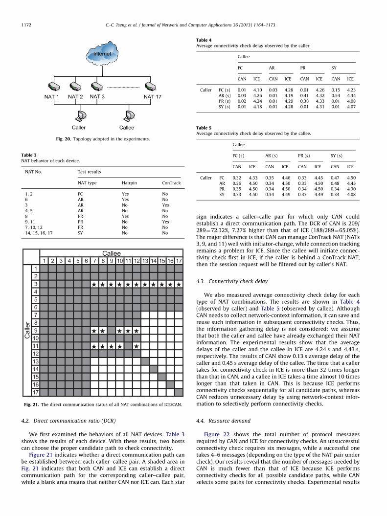
Since our experiments use 17 NAT devices, which results intotal 17n17¼289 possible NAT combinations for caller–calleepairs, manually setting up and running experiments, and collect-ing the results can be tedious and error prone. Therefore, wedesigned a fully mesh test bed as shown in Fig. 20 for a systematicperformance measurement. Caller and callee in this test bed canindependently select and switch to one NAT device.
NAT 1 NAT 2 NAT 3 NAT 17
Caller Callee
Internet
Fig. 20. Topology adopted in the experiments.
Table 3NAT behavior of each device.
NAT No. Test results
NAT type Hairpin ConTrack
1, 2 FC Yes No
6 AR Yes No
3 AR No Yes
4, 5 AR No No
8 PR Yes No
9, 11 PR No Yes
7, 10, 12 PR No No
14, 15, 16, 17 SY No No
Fig. 21. The direct communication status of all NAT combinations of ICE/CAN.
Table 4Average connectivity check delay observed by the caller.
Callee
FC AR PR SY
CAN ICE CAN ICE CAN ICE CAN ICE
Caller FC (s) 0.01 4.10 0.03 4.28 0.01 4.26 0.15 4.23
AR (s) 0.03 4.26 0.01 4.19 0.41 4.32 0.54 4.34
PR (s) 0.02 4.24 0.01 4.29 0.38 4.33 0.01 4.08
SY (s) 0.01 4.18 0.01 4.28 0.01 4.31 0.01 4.07
Table 5Average connectivity check delay observed by the callee.
Callee
FC (s) AR (s) PR (s) SY (s)
CAN ICE CAN ICE CAN ICE CAN ICE
Caller FC 0.32 4.33 0.35 4.46 0.33 4.45 0.47 4.50
AR 0.36 4.50 0.34 4.50 0.33 4.50 0.48 4.45
PR 0.35 4.50 0.34 4.50 0.34 4.50 0.34 4.30
SY 0.33 4.50 0.34 4.49 0.33 4.49 0.34 4.08
C.-C. Tseng et al. / Journal of Network and Computer Applications 36 (2013) 1164–11731172
4.2. Direct communication ratio (DCR)
We first examined the behaviors of all NAT devices. Table 3shows the results of each device. With these results, two hostscan choose the proper candidate path to check connectivity.
Figure 21 indicates whether a direct communication path canbe established between each caller–callee pair. A shaded area inFig. 21 indicates that both CAN and ICE can establish a directcommunication path for the corresponding caller–callee pair,while a blank area means that neither CAN nor ICE can. Each star
sign indicates a caller–calle pair for which only CAN couldestablish a direct communication path. The DCR of CAN is 209/289¼72.32%, 7.27% higher than that of ICE (188/289¼65.05%).The major difference is that CAN can manage ConTrack NAT (NATs3, 9, and 11) well with initiator-change, while connection trackingremains a problem for ICE. Since the callee will initiate connec-tivity check first in ICE, if the caller is behind a ConTrack NAT,then the session request will be filtered out by caller’s NAT.
4.3. Connectivity check delay
We also measured average connectivity check delay for eachtype of NAT combinations. The results are shown in Table 4(observed by caller) and Table 5 (observed by callee). AlthoughCAN needs to collect network-context information, it can save andreuse such information in subsequent connectivity checks. Thus,the information gathering delay is not considered: we assumethat both the caller and callee have already exchanged their NATinformation. The experimental results show that the averagedelays of the caller and the callee in ICE are 4.24 s and 4.43 s,respectively. The results of CAN show 0.13 s average delay of thecaller and 0.45 s average delay of the callee. The time that a callertakes for connectivity check in ICE is more than 32 times longerthan that in CAN, and a callee in ICE takes a time almost 10 timeslonger than that taken in CAN. This is because ICE performsconnectivity checks sequentially for all candidate paths, whereasCAN reduces unnecessary delay by using network-context infor-mation to selectively perform connectivity checks.
4.4. Resource demand
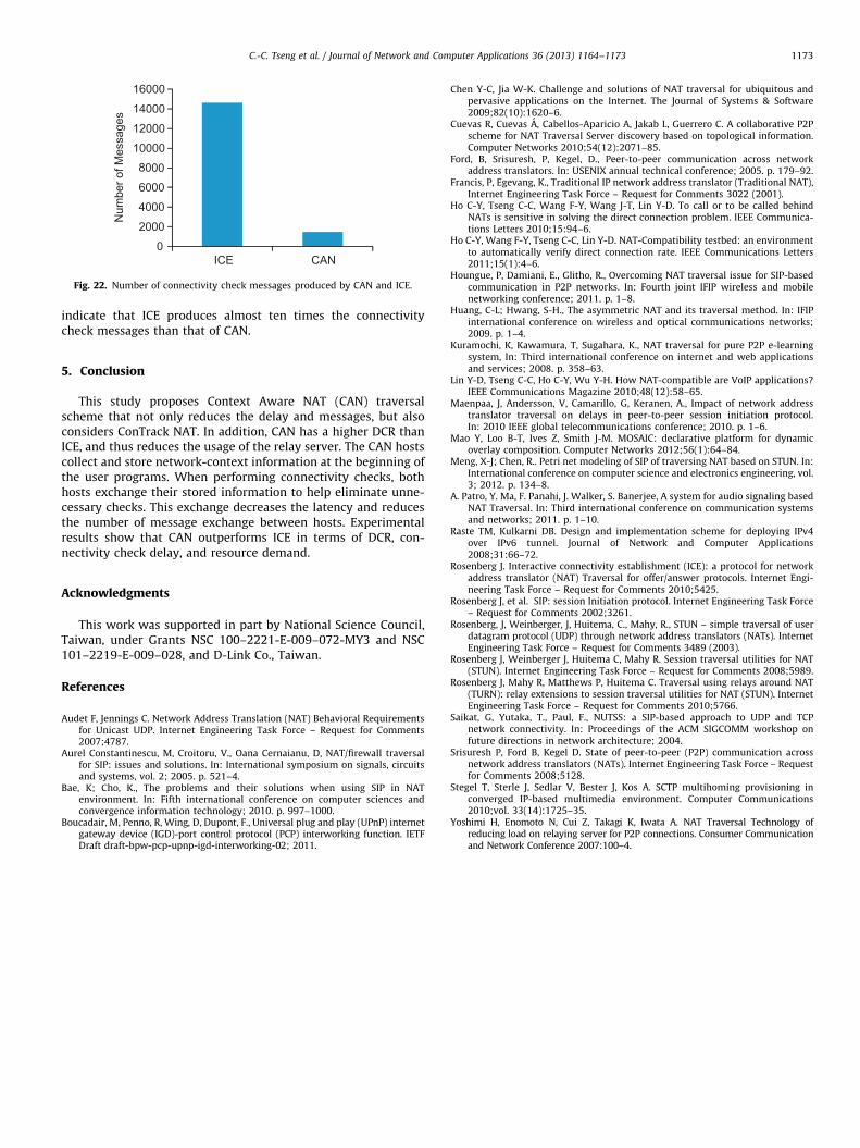
Figure 22 shows the total number of protocol messagesrequired by CAN and ICE for connectivity checks. An unsuccessfulconnectivity check requires six messages, while a successful onetakes 4–6 messages (depending on the type of the NAT pair undercheck). Our results reveal that the number of messages needed byCAN is much fewer than that of ICE because ICE performsconnectivity checks for all possible candidate paths, while CANselects some paths for connectivity checks. Experimental results
0
2000
4000
6000
8000
10000
12000
14000
16000
ICE CAN
Num
ber o
f Mes
sage
s
Fig. 22. Number of connectivity check messages produced by CAN and ICE.
C.-C. Tseng et al. / Journal of Network and Computer Applications 36 (2013) 1164–1173 1173
indicate that ICE produces almost ten times the connectivitycheck messages than that of CAN.
5. Conclusion
This study proposes Context Aware NAT (CAN) traversalscheme that not only reduces the delay and messages, but alsoconsiders ConTrack NAT. In addition, CAN has a higher DCR thanICE, and thus reduces the usage of the relay server. The CAN hostscollect and store network-context information at the beginning ofthe user programs. When performing connectivity checks, bothhosts exchange their stored information to help eliminate unne-cessary checks. This exchange decreases the latency and reducesthe number of message exchange between hosts. Experimentalresults show that CAN outperforms ICE in terms of DCR, con-nectivity check delay, and resource demand.
Acknowledgments
This work was supported in part by National Science Council,Taiwan, under Grants NSC 100–2221-E-009–072-MY3 and NSC101–2219-E-009–028, and D-Link Co., Taiwan.
References
Audet F, Jennings C. Network Address Translation (NAT) Behavioral Requirementsfor Unicast UDP. Internet Engineering Task Force – Request for Comments2007;4787.
Aurel Constantinescu, M, Croitoru, V., Oana Cernaianu, D, NAT/firewall traversalfor SIP: issues and solutions. In: International symposium on signals, circuitsand systems, vol. 2; 2005. p. 521–4.
Bae, K; Cho, K., The problems and their solutions when using SIP in NATenvironment. In: Fifth international conference on computer sciences andconvergence information technology; 2010. p. 997–1000.
Boucadair, M, Penno, R, Wing, D, Dupont, F., Universal plug and play (UPnP) internetgateway device (IGD)-port control protocol (PCP) interworking function. IETFDraft draft-bpw-pcp-upnp-igd-interworking-02; 2011.
Chen Y-C, Jia W-K. Challenge and solutions of NAT traversal for ubiquitous andpervasive applications on the Internet. The Journal of Systems & Software2009;82(10):1620–6.
Cuevas R, Cuevas A, Cabellos-Aparicio A, Jakab L, Guerrero C. A collaborative P2Pscheme for NAT Traversal Server discovery based on topological information.Computer Networks 2010;54(12):2071–85.
Ford, B, Srisuresh, P, Kegel, D., Peer-to-peer communication across networkaddress translators. In: USENIX annual technical conference; 2005. p. 179–92.
Francis, P, Egevang, K., Traditional IP network address translator (Traditional NAT),Internet Engineering Task Force – Request for Comments 3022 (2001).
Ho C-Y, Tseng C-C, Wang F-Y, Wang J-T, Lin Y-D. To call or to be called behindNATs is sensitive in solving the direct connection problem. IEEE Communica-tions Letters 2010;15:94–6.
Ho C-Y, Wang F-Y, Tseng C-C, Lin Y-D. NAT-Compatibility testbed: an environmentto automatically verify direct connection rate. IEEE Communications Letters2011;15(1):4–6.
Houngue, P, Damiani, E., Glitho, R., Overcoming NAT traversal issue for SIP-basedcommunication in P2P networks. In: Fourth joint IFIP wireless and mobilenetworking conference; 2011. p. 1–8.
Huang, C-L; Hwang, S-H., The asymmetric NAT and its traversal method. In: IFIPinternational conference on wireless and optical communications networks;2009. p. 1–4.
Kuramochi, K, Kawamura, T, Sugahara, K., NAT traversal for pure P2P e-learningsystem, In: Third international conference on internet and web applicationsand services; 2008. p. 358–63.
Lin Y-D, Tseng C-C, Ho C-Y, Wu Y-H. How NAT-compatible are VoIP applications?IEEE Communications Magazine 2010;48(12):58–65.
Maenpaa, J, Andersson, V, Camarillo, G, Keranen, A., Impact of network addresstranslator traversal on delays in peer-to-peer session initiation protocol.In: 2010 IEEE global telecommunications conference; 2010. p. 1–6.
Mao Y, Loo B-T, Ives Z, Smith J-M. MOSAIC: declarative platform for dynamicoverlay composition. Computer Networks 2012;56(1):64–84.
Meng, X-J; Chen, R.. Petri net modeling of SIP of traversing NAT based on STUN. In:International conference on computer science and electronics engineering, vol.3; 2012. p. 134–8.
A. Patro, Y. Ma, F. Panahi, J. Walker, S. Banerjee, A system for audio signaling basedNAT Traversal. In: Third international conference on communication systemsand networks; 2011. p. 1–10.
Raste TM, Kulkarni DB. Design and implementation scheme for deploying IPv4over IPv6 tunnel. Journal of Network and Computer Applications2008;31:66–72.
Rosenberg J. Interactive connectivity establishment (ICE): a protocol for networkaddress translator (NAT) Traversal for offer/answer protocols. Internet Engi-neering Task Force – Request for Comments 2010;5425.
Rosenberg J, et al. SIP: session Initiation protocol. Internet Engineering Task Force– Request for Comments 2002;3261.
Rosenberg, J, Weinberger, J, Huitema, C., Mahy, R., STUN – simple traversal of userdatagram protocol (UDP) through network address translators (NATs). InternetEngineering Task Force – Request for Comments 3489 (2003).
Rosenberg J, Weinberger J, Huitema C, Mahy R. Session traversal utilities for NAT(STUN). Internet Engineering Task Force – Request for Comments 2008;5989.
Rosenberg J, Mahy R, Matthews P, Huitema C. Traversal using relays around NAT(TURN): relay extensions to session traversal utilities for NAT (STUN). InternetEngineering Task Force – Request for Comments 2010;5766.
Saikat, G, Yutaka, T., Paul, F., NUTSS: a SIP-based approach to UDP and TCPnetwork connectivity. In: Proceedings of the ACM SIGCOMM workshop onfuture directions in network architecture; 2004.
Srisuresh P, Ford B, Kegel D. State of peer-to-peer (P2P) communication acrossnetwork address translators (NATs). Internet Engineering Task Force – Requestfor Comments 2008;5128.
Stegel T, Sterle J, Sedlar V, Bester J, Kos A. SCTP multihoming provisioning inconverged IP-based multimedia environment. Computer Communications2010;vol. 33(14):1725–35.
Yoshimi H, Enomoto N, Cui Z, Takagi K, Iwata A. NAT Traversal Technology ofreducing load on relaying server for P2P connections. Consumer Communicationand Network Conference 2007:100–4.