Embed Size (px)
Citation preview
Cadence AMS Simulator User Guide
Product Version 1.0July 2001

2000-2001 Cadence Design Systems, Inc. All rights reserved.Printed in the United States of America.
Cadence Design Systems, Inc., 555 River Oaks Parkway, San Jose, CA 95134, USA
Trademarks: Trademarks and service marks of Cadence Design Systems, Inc. (Cadence) contained in thisdocument are attributed to Cadence with the appropriate symbol. For queries regarding Cadence’s trademarks,contact the corporate legal department at the address shown above or call 1-800-862-4522.
All other trademarks are the property of their respective holders.
Restricted Print Permission: This publication is protected by copyright and any unauthorized use of thispublication may violate copyright, trademark, and other laws. Except as specified in this permission statement,this publication may not be copied, reproduced, modified, published, uploaded, posted, transmitted, ordistributed in any way, without prior written permission from Cadence. This statement grants you permission toprint one (1) hard copy of this publication subject to the following conditions:
1. The publication may be used solely for personal, informational, and noncommercial purposes;2. The publication may not be modified in any way;3. Any copy of the publication or portion thereof must include all original copyright, trademark, and other
proprietary notices and this permission statement; and4. Cadence reserves the right to revoke this authorization at any time, and any such use shall be
discontinued immediately upon written notice from Cadence.
Disclaimer: Information in this publication is subject to change without notice and does not represent acommitment on the part of Cadence. The information contained herein is the proprietary and confidentialinformation of Cadence or its licensors, and is supplied subject to, and may be used only by Cadence’s customerin accordance with, a written agreement between Cadence and its customer. Except as may be explicitly setforth in such agreement, Cadence does not make, and expressly disclaims, any representations or warrantiesas to the completeness, accuracy or usefulness of the information contained in this document. Cadence doesnot warrant that use of such information will not infringe any third party rights, nor does Cadence assume anyliability for damages or costs of any kind that may result from use of such information.
Restricted Rights: Use, duplication, or disclosure by the Government is subject to restrictions as set forth inFAR52.227-14 and DFAR252.227-7013 et seq. or its successor.
Cadence AMS Simulator User Guide
Contents
Preface .......................................................................................................................... 12
Related Documents . . . . . . . . . . . . . . . . . . . . . . . . . . . . . . . . . . . . . . . . . . . . . . . . . . . . . 12Typographic and Syntax Conventions . . . . . . . . . . . . . . . . . . . . . . . . . . . . . . . . . . . . . . . 13
1Getting Started with the AMS Simulator . . . . . . . . . . . . . . . . . . . . . . . 15
Language Support . . . . . . . . . . . . . . . . . . . . . . . . . . . . . . . . . . . . . . . . . . . . . . . . . . . . . . 16Memory Requirements . . . . . . . . . . . . . . . . . . . . . . . . . . . . . . . . . . . . . . . . . . . . . . . . . . 16Setting Up Your Design Environment . . . . . . . . . . . . . . . . . . . . . . . . . . . . . . . . . . . . . . . . 16Running the Cadence AMS Simulator . . . . . . . . . . . . . . . . . . . . . . . . . . . . . . . . . . . . . . . 18Running ncverilog with a Single Step . . . . . . . . . . . . . . . . . . . . . . . . . . . . . . . . . . . . . . . 22Running the Simulator Using Multiple Steps . . . . . . . . . . . . . . . . . . . . . . . . . . . . . . . . . . 23Understanding the Simulator Library Databases . . . . . . . . . . . . . . . . . . . . . . . . . . . . . . . 24Using a Configuration . . . . . . . . . . . . . . . . . . . . . . . . . . . . . . . . . . . . . . . . . . . . . . . . . . . 25
2Running With the ncverilog Command. . . . . . . . . . . . . . . . . . . . . . . . . 26
Overview . . . . . . . . . . . . . . . . . . . . . . . . . . . . . . . . . . . . . . . . . . . . . . . . . . . . . . . . . . . . . 27How ncverilog Works . . . . . . . . . . . . . . . . . . . . . . . . . . . . . . . . . . . . . . . . . . . . . . . . . . . . 29ncverilog Command Syntax and Options . . . . . . . . . . . . . . . . . . . . . . . . . . . . . . . . . . . . 30
ncverilog Command Option Details . . . . . . . . . . . . . . . . . . . . . . . . . . . . . . . . . . . . . . 32
3Setting Up Your Environment. . . . . . . . . . . . . . . . . . . . . . . . . . . . . . . . . . . . 35
Overview . . . . . . . . . . . . . . . . . . . . . . . . . . . . . . . . . . . . . . . . . . . . . . . . . . . . . . . . . . . . . 36The Library.Cell:View Approach . . . . . . . . . . . . . . . . . . . . . . . . . . . . . . . . . . . . . . . . . . . . 36The cds.lib File . . . . . . . . . . . . . . . . . . . . . . . . . . . . . . . . . . . . . . . . . . . . . . . . . . . . . . . . . 37
The Work Library . . . . . . . . . . . . . . . . . . . . . . . . . . . . . . . . . . . . . . . . . . . . . . . . . . . . 38cds.lib Statements . . . . . . . . . . . . . . . . . . . . . . . . . . . . . . . . . . . . . . . . . . . . . . . . . . . 39cds.lib Syntax Rules . . . . . . . . . . . . . . . . . . . . . . . . . . . . . . . . . . . . . . . . . . . . . . . . . . 40
July 2001 3 Product Version 1.0
Cadence AMS Simulator User Guide
Example cds.lib File . . . . . . . . . . . . . . . . . . . . . . . . . . . . . . . . . . . . . . . . . . . . . . . . . . 42Binding One Library to Multiple Directories . . . . . . . . . . . . . . . . . . . . . . . . . . . . . . . . 42Directory Binding Rules . . . . . . . . . . . . . . . . . . . . . . . . . . . . . . . . . . . . . . . . . . . . . . . 43Debugging cds.lib Files . . . . . . . . . . . . . . . . . . . . . . . . . . . . . . . . . . . . . . . . . . . . . . . 43
The hdl.var File . . . . . . . . . . . . . . . . . . . . . . . . . . . . . . . . . . . . . . . . . . . . . . . . . . . . . . . . 45hdl.var Statements . . . . . . . . . . . . . . . . . . . . . . . . . . . . . . . . . . . . . . . . . . . . . . . . . . . 46hdl.var Variables . . . . . . . . . . . . . . . . . . . . . . . . . . . . . . . . . . . . . . . . . . . . . . . . . . . . . 47hdl.var Syntax Rules . . . . . . . . . . . . . . . . . . . . . . . . . . . . . . . . . . . . . . . . . . . . . . . . . . 53Example hdl.var File . . . . . . . . . . . . . . . . . . . . . . . . . . . . . . . . . . . . . . . . . . . . . . . . . . 55Debugging hdl.var Files . . . . . . . . . . . . . . . . . . . . . . . . . . . . . . . . . . . . . . . . . . . . . . . 55
The setup.loc File . . . . . . . . . . . . . . . . . . . . . . . . . . . . . . . . . . . . . . . . . . . . . . . . . . . . . . . 56setup.loc Syntax Rules . . . . . . . . . . . . . . . . . . . . . . . . . . . . . . . . . . . . . . . . . . . . . . . . 56
Directory Structure Example . . . . . . . . . . . . . . . . . . . . . . . . . . . . . . . . . . . . . . . . . . . . . . 57
4Instantiating Analog Primitives and Subcircuits . . . . . . . . . . . . . . . 61
Overview . . . . . . . . . . . . . . . . . . . . . . . . . . . . . . . . . . . . . . . . . . . . . . . . . . . . . . . . . . . . . 62Using Spectre Built-In and Verilog-AMS Primitives . . . . . . . . . . . . . . . . . . . . . . . . . . . . . 62Using Subcircuits and Models Written in SPICE or Spectre . . . . . . . . . . . . . . . . . . . . . . 63
Creating an Analog Primitive Table . . . . . . . . . . . . . . . . . . . . . . . . . . . . . . . . . . . . . . 63Passing the Location of the Analog Primitive Table to the Compiler and Elaborator . 64
Using Inline Subcircuits . . . . . . . . . . . . . . . . . . . . . . . . . . . . . . . . . . . . . . . . . . . . . . . . . . 64
5Importing Verilog-AMS Modules into VHDL Modules . . . . . . . . 65
Overview . . . . . . . . . . . . . . . . . . . . . . . . . . . . . . . . . . . . . . . . . . . . . . . . . . . . . . . . . . . . . 66Generating a Shell with ncshell . . . . . . . . . . . . . . . . . . . . . . . . . . . . . . . . . . . . . . . . . . . . 66
Restrictions . . . . . . . . . . . . . . . . . . . . . . . . . . . . . . . . . . . . . . . . . . . . . . . . . . . . . . . . . 67Steps to Follow . . . . . . . . . . . . . . . . . . . . . . . . . . . . . . . . . . . . . . . . . . . . . . . . . . . . . . 67Example . . . . . . . . . . . . . . . . . . . . . . . . . . . . . . . . . . . . . . . . . . . . . . . . . . . . . . . . . . . 68
July 2001 4 Product Version 1.0
Cadence AMS Simulator User Guide
6Compiling . . . . . . . . . . . . . . . . . . . . . . . . . . . . . . . . . . . . . . . . . . . . . . . . . . . . . . . . . . 71
Overview . . . . . . . . . . . . . . . . . . . . . . . . . . . . . . . . . . . . . . . . . . . . . . . . . . . . . . . . . . . . . 72ncvlog Command Syntax . . . . . . . . . . . . . . . . . . . . . . . . . . . . . . . . . . . . . . . . . . . . . . . . . 73
ncvlog Command Options Details . . . . . . . . . . . . . . . . . . . . . . . . . . . . . . . . . . . . . . . 75Example ncvlog Command Lines . . . . . . . . . . . . . . . . . . . . . . . . . . . . . . . . . . . . . . . . 77
hdl.var Variables . . . . . . . . . . . . . . . . . . . . . . . . . . . . . . . . . . . . . . . . . . . . . . . . . . . . . . . 78Conditionally Compiling Source Code . . . . . . . . . . . . . . . . . . . . . . . . . . . . . . . . . . . . . . . 79Controlling the Compilation of Design Units into Library.Cell:View . . . . . . . . . . . . . . . . . 80
7Elaborating . . . . . . . . . . . . . . . . . . . . . . . . . . . . . . . . . . . . . . . . . . . . . . . . . . . . . . . . 81
Overview . . . . . . . . . . . . . . . . . . . . . . . . . . . . . . . . . . . . . . . . . . . . . . . . . . . . . . . . . . . . . 82ncelab Command Syntax and Options . . . . . . . . . . . . . . . . . . . . . . . . . . . . . . . . . . . . . . 83
ncelab Command Options Details . . . . . . . . . . . . . . . . . . . . . . . . . . . . . . . . . . . . . . . 89Example ncelab Command Lines . . . . . . . . . . . . . . . . . . . . . . . . . . . . . . . . . . . . . . . . 91
hdl.var Variables . . . . . . . . . . . . . . . . . . . . . . . . . . . . . . . . . . . . . . . . . . . . . . . . . . . . . . . 92How Modules and UDPs Are Resolved During Elaboration . . . . . . . . . . . . . . . . . . . . . . 93Enabling Read, Write, or Connectivity Access to Digital Simulation Objects . . . . . . . . . . 94Selecting a Delay Mode . . . . . . . . . . . . . . . . . . . . . . . . . . . . . . . . . . . . . . . . . . . . . . . . . . 95Setting Pulse Controls . . . . . . . . . . . . . . . . . . . . . . . . . . . . . . . . . . . . . . . . . . . . . . . . . . . 95
8Specifying Controls for the Analog Solver . . . . . . . . . . . . . . . . . . . . . 96
Language Mode (lang) . . . . . . . . . . . . . . . . . . . . . . . . . . . . . . . . . . . . . . . . . . . . . . . . . . . 97Immediate Set Options (options) . . . . . . . . . . . . . . . . . . . . . . . . . . . . . . . . . . . . . . . . . . . 97Initial Guess (nodeset) . . . . . . . . . . . . . . . . . . . . . . . . . . . . . . . . . . . . . . . . . . . . . . . . . . 100Transient Analysis (tran) . . . . . . . . . . . . . . . . . . . . . . . . . . . . . . . . . . . . . . . . . . . . . . . . 100Initial Conditions (ic) . . . . . . . . . . . . . . . . . . . . . . . . . . . . . . . . . . . . . . . . . . . . . . . . . . . 102Displaying and Saving Information (info) . . . . . . . . . . . . . . . . . . . . . . . . . . . . . . . . . . . . 102
what . . . . . . . . . . . . . . . . . . . . . . . . . . . . . . . . . . . . . . . . . . . . . . . . . . . . . . . . . . . . . 103where . . . . . . . . . . . . . . . . . . . . . . . . . . . . . . . . . . . . . . . . . . . . . . . . . . . . . . . . . . . . 104file . . . . . . . . . . . . . . . . . . . . . . . . . . . . . . . . . . . . . . . . . . . . . . . . . . . . . . . . . . . . . . . 104save . . . . . . . . . . . . . . . . . . . . . . . . . . . . . . . . . . . . . . . . . . . . . . . . . . . . . . . . . . . . . 104
July 2001 5 Product Version 1.0
Cadence AMS Simulator User Guide
extremes . . . . . . . . . . . . . . . . . . . . . . . . . . . . . . . . . . . . . . . . . . . . . . . . . . . . . . . . . . 105title . . . . . . . . . . . . . . . . . . . . . . . . . . . . . . . . . . . . . . . . . . . . . . . . . . . . . . . . . . . . . . 105
9Simulating . . . . . . . . . . . . . . . . . . . . . . . . . . . . . . . . . . . . . . . . . . . . . . . . . . . . . . . . 106
Overview . . . . . . . . . . . . . . . . . . . . . . . . . . . . . . . . . . . . . . . . . . . . . . . . . . . . . . . . . . . . 107ncsim Command Syntax and Options . . . . . . . . . . . . . . . . . . . . . . . . . . . . . . . . . . . . . . 108
ncsim Command Option Details . . . . . . . . . . . . . . . . . . . . . . . . . . . . . . . . . . . . . . . . 110Example ncsim Command Lines . . . . . . . . . . . . . . . . . . . . . . . . . . . . . . . . . . . . . . . 111
hdl.var Variables . . . . . . . . . . . . . . . . . . . . . . . . . . . . . . . . . . . . . . . . . . . . . . . . . . . . . . 112Running the Simulator . . . . . . . . . . . . . . . . . . . . . . . . . . . . . . . . . . . . . . . . . . . . . . . . . . 112Starting a Simulation . . . . . . . . . . . . . . . . . . . . . . . . . . . . . . . . . . . . . . . . . . . . . . . . . . . 113Updating Design Changes When You Run the Simulator . . . . . . . . . . . . . . . . . . . . . . . 114Providing Interactive Commands from a File . . . . . . . . . . . . . . . . . . . . . . . . . . . . . . . . . 114Exiting the Simulation . . . . . . . . . . . . . . . . . . . . . . . . . . . . . . . . . . . . . . . . . . . . . . . . . . 115
10Debugging . . . . . . . . . . . . . . . . . . . . . . . . . . . . . . . . . . . . . . . . . . . . . . . . . . . . . . . . 116
Terminology . . . . . . . . . . . . . . . . . . . . . . . . . . . . . . . . . . . . . . . . . . . . . . . . . . . . . . . . . . 117Managing Databases . . . . . . . . . . . . . . . . . . . . . . . . . . . . . . . . . . . . . . . . . . . . . . . . . . . 117
Opening a Database . . . . . . . . . . . . . . . . . . . . . . . . . . . . . . . . . . . . . . . . . . . . . . . . 118Displaying Information About Databases . . . . . . . . . . . . . . . . . . . . . . . . . . . . . . . . . 118Disabling a Database . . . . . . . . . . . . . . . . . . . . . . . . . . . . . . . . . . . . . . . . . . . . . . . . 119Enabling a Database . . . . . . . . . . . . . . . . . . . . . . . . . . . . . . . . . . . . . . . . . . . . . . . . 119Closing a Database . . . . . . . . . . . . . . . . . . . . . . . . . . . . . . . . . . . . . . . . . . . . . . . . . 119
Setting and Deleting Probes . . . . . . . . . . . . . . . . . . . . . . . . . . . . . . . . . . . . . . . . . . . . . 119Setting a Probe . . . . . . . . . . . . . . . . . . . . . . . . . . . . . . . . . . . . . . . . . . . . . . . . . . . . . 120Displaying Information About Probes . . . . . . . . . . . . . . . . . . . . . . . . . . . . . . . . . . . . 121Disabling a Probe . . . . . . . . . . . . . . . . . . . . . . . . . . . . . . . . . . . . . . . . . . . . . . . . . . . 121Enabling a Probe . . . . . . . . . . . . . . . . . . . . . . . . . . . . . . . . . . . . . . . . . . . . . . . . . . . 121Deleting a Probe . . . . . . . . . . . . . . . . . . . . . . . . . . . . . . . . . . . . . . . . . . . . . . . . . . . . 121
Traversing the Model Hierarchy . . . . . . . . . . . . . . . . . . . . . . . . . . . . . . . . . . . . . . . . . . . 122Setting Breakpoints . . . . . . . . . . . . . . . . . . . . . . . . . . . . . . . . . . . . . . . . . . . . . . . . . . . . 125
Setting a Condition Breakpoint . . . . . . . . . . . . . . . . . . . . . . . . . . . . . . . . . . . . . . . . . 125Setting a Source Code Line Breakpoint . . . . . . . . . . . . . . . . . . . . . . . . . . . . . . . . . . 126
July 2001 6 Product Version 1.0
Cadence AMS Simulator User Guide
Setting an Object Breakpoint . . . . . . . . . . . . . . . . . . . . . . . . . . . . . . . . . . . . . . . . . . 127Setting a Time Breakpoint . . . . . . . . . . . . . . . . . . . . . . . . . . . . . . . . . . . . . . . . . . . . 128Setting a Delta Breakpoint . . . . . . . . . . . . . . . . . . . . . . . . . . . . . . . . . . . . . . . . . . . . 128Setting a Process Breakpoint . . . . . . . . . . . . . . . . . . . . . . . . . . . . . . . . . . . . . . . . . . 129
Disabling, Enabling, Deleting, and Displaying Breakpoints . . . . . . . . . . . . . . . . . . . . . . 129Stepping Through Lines of Code . . . . . . . . . . . . . . . . . . . . . . . . . . . . . . . . . . . . . . . . . . 130Forcing and Releasing Signal Values . . . . . . . . . . . . . . . . . . . . . . . . . . . . . . . . . . . . . . 131Depositing Values to Signals . . . . . . . . . . . . . . . . . . . . . . . . . . . . . . . . . . . . . . . . . . . . . 131Displaying Information About Simulation Objects . . . . . . . . . . . . . . . . . . . . . . . . . . . . . 132Displaying the Drivers of Signals . . . . . . . . . . . . . . . . . . . . . . . . . . . . . . . . . . . . . . . . . . 133Debugging Designs with Automatically-Inserted Connect Modules . . . . . . . . . . . . . . . 134Displaying Waveforms with Signalscan waves . . . . . . . . . . . . . . . . . . . . . . . . . . . . . . . . 134
Creating a Database and Probing Signals . . . . . . . . . . . . . . . . . . . . . . . . . . . . . . . . 135Opening a Database with $shm_open . . . . . . . . . . . . . . . . . . . . . . . . . . . . . . . . . . . 136Probing Signals with $shm_probe . . . . . . . . . . . . . . . . . . . . . . . . . . . . . . . . . . . . . . 137Invoking Signalscan waves . . . . . . . . . . . . . . . . . . . . . . . . . . . . . . . . . . . . . . . . . . . . 138
July 2001 7 Product Version 1.0
Cadence AMS Simulator User Guide
Comparing Databases with Comparescan . . . . . . . . . . . . . . . . . . . . . . . . . . . . . . . . . . 140Displaying Debug Settings . . . . . . . . . . . . . . . . . . . . . . . . . . . . . . . . . . . . . . . . . . . . . . . 140Setting a Default Radix . . . . . . . . . . . . . . . . . . . . . . . . . . . . . . . . . . . . . . . . . . . . . . . . . 141Setting the Format for Branches . . . . . . . . . . . . . . . . . . . . . . . . . . . . . . . . . . . . . . . . . . 141Setting the Format for Potential and Flow . . . . . . . . . . . . . . . . . . . . . . . . . . . . . . . . . . . 142Setting Variables . . . . . . . . . . . . . . . . . . . . . . . . . . . . . . . . . . . . . . . . . . . . . . . . . . . . . . 142Editing a Source File . . . . . . . . . . . . . . . . . . . . . . . . . . . . . . . . . . . . . . . . . . . . . . . . . . . 146Searching for a Line Number in the Source Code . . . . . . . . . . . . . . . . . . . . . . . . . . . . . 147Searching for a Text String in the Source Code . . . . . . . . . . . . . . . . . . . . . . . . . . . . . . . 147Configuring Your Simulation Environment . . . . . . . . . . . . . . . . . . . . . . . . . . . . . . . . . . . 147Saving and Restoring Your Simulation Environment . . . . . . . . . . . . . . . . . . . . . . . . . . . 148Creating or Deleting an Alias . . . . . . . . . . . . . . . . . . . . . . . . . . . . . . . . . . . . . . . . . . . . . 149Getting a History of Commands . . . . . . . . . . . . . . . . . . . . . . . . . . . . . . . . . . . . . . . . . . . 149Managing Custom Buttons . . . . . . . . . . . . . . . . . . . . . . . . . . . . . . . . . . . . . . . . . . . . . . 150
11Time-Saving Techniques for the Analog Solver . . . . . . . . . . . . . . 151
Adjusting Speed and Accuracy . . . . . . . . . . . . . . . . . . . . . . . . . . . . . . . . . . . . . . . . . . . 152Saving Time by Selecting a Continuation Method . . . . . . . . . . . . . . . . . . . . . . . . . . . . . 152Specifying Efficient Starting Points . . . . . . . . . . . . . . . . . . . . . . . . . . . . . . . . . . . . . . . . 152
Saving Time by Specifying State Information . . . . . . . . . . . . . . . . . . . . . . . . . . . . . . 153
July 2001 8 Product Version 1.0
Cadence AMS Simulator User Guide
AUpdating Legacy Libraries and Netlists . . . . . . . . . . . . . . . . . . . . . . . 157
Updating Verilog-A Modules . . . . . . . . . . . . . . . . . . . . . . . . . . . . . . . . . . . . . . . . . . . . . 157Updating SpectreHDL Modules . . . . . . . . . . . . . . . . . . . . . . . . . . . . . . . . . . . . . . . . . . . 157Updating Libraries of Analog Masters . . . . . . . . . . . . . . . . . . . . . . . . . . . . . . . . . . . . . . 157Updating Verilog Modules . . . . . . . . . . . . . . . . . . . . . . . . . . . . . . . . . . . . . . . . . . . . . . . 158Updating VHDL Blocks . . . . . . . . . . . . . . . . . . . . . . . . . . . . . . . . . . . . . . . . . . . . . . . . . 158Updating Legacy Netlists . . . . . . . . . . . . . . . . . . . . . . . . . . . . . . . . . . . . . . . . . . . . . . . . 158Updating Existing Designs . . . . . . . . . . . . . . . . . . . . . . . . . . . . . . . . . . . . . . . . . . . . . . . 159
BTcl-Based Debugging . . . . . . . . . . . . . . . . . . . . . . . . . . . . . . . . . . . . . . . . . . . 160
Overview . . . . . . . . . . . . . . . . . . . . . . . . . . . . . . . . . . . . . . . . . . . . . . . . . . . . . . . . . . . . 160Specifying Unnamed Branch Objects . . . . . . . . . . . . . . . . . . . . . . . . . . . . . . . . . . . . 160Example Tcl Commands . . . . . . . . . . . . . . . . . . . . . . . . . . . . . . . . . . . . . . . . . . . . . 161
List of Tcl Commands . . . . . . . . . . . . . . . . . . . . . . . . . . . . . . . . . . . . . . . . . . . . . . . . . . 161call . . . . . . . . . . . . . . . . . . . . . . . . . . . . . . . . . . . . . . . . . . . . . . . . . . . . . . . . . . . . . . . . . 165
call Command Syntax . . . . . . . . . . . . . . . . . . . . . . . . . . . . . . . . . . . . . . . . . . . . . . . 165call Command Modifiers and Options . . . . . . . . . . . . . . . . . . . . . . . . . . . . . . . . . . . 167call Command Examples . . . . . . . . . . . . . . . . . . . . . . . . . . . . . . . . . . . . . . . . . . . . . 167
deposit . . . . . . . . . . . . . . . . . . . . . . . . . . . . . . . . . . . . . . . . . . . . . . . . . . . . . . . . . . . . . . 168deposit Command Syntax . . . . . . . . . . . . . . . . . . . . . . . . . . . . . . . . . . . . . . . . . . . . 169deposit Command Modifiers and Options . . . . . . . . . . . . . . . . . . . . . . . . . . . . . . . . 170deposit Command Examples . . . . . . . . . . . . . . . . . . . . . . . . . . . . . . . . . . . . . . . . . . 170
describe . . . . . . . . . . . . . . . . . . . . . . . . . . . . . . . . . . . . . . . . . . . . . . . . . . . . . . . . . . . . . 171describe Command Syntax . . . . . . . . . . . . . . . . . . . . . . . . . . . . . . . . . . . . . . . . . . . 172describe Command Modifiers and Options . . . . . . . . . . . . . . . . . . . . . . . . . . . . . . . 172describe Command Examples . . . . . . . . . . . . . . . . . . . . . . . . . . . . . . . . . . . . . . . . . 172
drivers . . . . . . . . . . . . . . . . . . . . . . . . . . . . . . . . . . . . . . . . . . . . . . . . . . . . . . . . . . . . . . 174drivers Command Syntax . . . . . . . . . . . . . . . . . . . . . . . . . . . . . . . . . . . . . . . . . . . . . 174drivers Command Modifiers and Options . . . . . . . . . . . . . . . . . . . . . . . . . . . . . . . . . 175drivers Command Report Format . . . . . . . . . . . . . . . . . . . . . . . . . . . . . . . . . . . . . . . 175drivers Command Examples . . . . . . . . . . . . . . . . . . . . . . . . . . . . . . . . . . . . . . . . . . 179
July 2001 9 Product Version 1.0
Cadence AMS Simulator User Guide
finish . . . . . . . . . . . . . . . . . . . . . . . . . . . . . . . . . . . . . . . . . . . . . . . . . . . . . . . . . . . . . . . 182finish Command Syntax . . . . . . . . . . . . . . . . . . . . . . . . . . . . . . . . . . . . . . . . . . . . . . 182finish Command Modifiers and Options . . . . . . . . . . . . . . . . . . . . . . . . . . . . . . . . . . 182finish Command Examples . . . . . . . . . . . . . . . . . . . . . . . . . . . . . . . . . . . . . . . . . . . . 183
force . . . . . . . . . . . . . . . . . . . . . . . . . . . . . . . . . . . . . . . . . . . . . . . . . . . . . . . . . . . . . . . . 183force Command Syntax . . . . . . . . . . . . . . . . . . . . . . . . . . . . . . . . . . . . . . . . . . . . . . 184force Command Modifiers and Options . . . . . . . . . . . . . . . . . . . . . . . . . . . . . . . . . . 184force Command Examples . . . . . . . . . . . . . . . . . . . . . . . . . . . . . . . . . . . . . . . . . . . . 184
probe . . . . . . . . . . . . . . . . . . . . . . . . . . . . . . . . . . . . . . . . . . . . . . . . . . . . . . . . . . . . . . . 185probe Command Syntax . . . . . . . . . . . . . . . . . . . . . . . . . . . . . . . . . . . . . . . . . . . . . . 187probe Command Modifiers and Options . . . . . . . . . . . . . . . . . . . . . . . . . . . . . . . . . . 188probe Command Examples . . . . . . . . . . . . . . . . . . . . . . . . . . . . . . . . . . . . . . . . . . . 193
release . . . . . . . . . . . . . . . . . . . . . . . . . . . . . . . . . . . . . . . . . . . . . . . . . . . . . . . . . . . . . . 196release Command Syntax . . . . . . . . . . . . . . . . . . . . . . . . . . . . . . . . . . . . . . . . . . . . 197release Command Modifiers and Options . . . . . . . . . . . . . . . . . . . . . . . . . . . . . . . . 197release Command Examples . . . . . . . . . . . . . . . . . . . . . . . . . . . . . . . . . . . . . . . . . . 197
reset . . . . . . . . . . . . . . . . . . . . . . . . . . . . . . . . . . . . . . . . . . . . . . . . . . . . . . . . . . . . . . . . 198reset Command Syntax . . . . . . . . . . . . . . . . . . . . . . . . . . . . . . . . . . . . . . . . . . . . . . 198reset Command Modifiers and Options . . . . . . . . . . . . . . . . . . . . . . . . . . . . . . . . . . 198reset Command Examples . . . . . . . . . . . . . . . . . . . . . . . . . . . . . . . . . . . . . . . . . . . . 198
restart . . . . . . . . . . . . . . . . . . . . . . . . . . . . . . . . . . . . . . . . . . . . . . . . . . . . . . . . . . . . . . 199restart Command Syntax . . . . . . . . . . . . . . . . . . . . . . . . . . . . . . . . . . . . . . . . . . . . . 200restart Command Modifiers and Options . . . . . . . . . . . . . . . . . . . . . . . . . . . . . . . . . 200restart Command Examples . . . . . . . . . . . . . . . . . . . . . . . . . . . . . . . . . . . . . . . . . . . 200
run . . . . . . . . . . . . . . . . . . . . . . . . . . . . . . . . . . . . . . . . . . . . . . . . . . . . . . . . . . . . . . . . . 202run Command Syntax . . . . . . . . . . . . . . . . . . . . . . . . . . . . . . . . . . . . . . . . . . . . . . . . 202run Command Modifiers and Options . . . . . . . . . . . . . . . . . . . . . . . . . . . . . . . . . . . . 203run Command Examples . . . . . . . . . . . . . . . . . . . . . . . . . . . . . . . . . . . . . . . . . . . . . 205
save . . . . . . . . . . . . . . . . . . . . . . . . . . . . . . . . . . . . . . . . . . . . . . . . . . . . . . . . . . . . . . . . 206save Command Syntax . . . . . . . . . . . . . . . . . . . . . . . . . . . . . . . . . . . . . . . . . . . . . . 207save Command Modifiers and Options . . . . . . . . . . . . . . . . . . . . . . . . . . . . . . . . . . 208save Command Examples . . . . . . . . . . . . . . . . . . . . . . . . . . . . . . . . . . . . . . . . . . . . 208
scope . . . . . . . . . . . . . . . . . . . . . . . . . . . . . . . . . . . . . . . . . . . . . . . . . . . . . . . . . . . . . . . 212scope Command Syntax . . . . . . . . . . . . . . . . . . . . . . . . . . . . . . . . . . . . . . . . . . . . . 213scope Command Modifiers and Options . . . . . . . . . . . . . . . . . . . . . . . . . . . . . . . . . 213scope Command Examples . . . . . . . . . . . . . . . . . . . . . . . . . . . . . . . . . . . . . . . . . . . 216
July 2001 10 Product Version 1.0
Cadence AMS Simulator User Guide
status . . . . . . . . . . . . . . . . . . . . . . . . . . . . . . . . . . . . . . . . . . . . . . . . . . . . . . . . . . . . . . . 221status Command Syntax . . . . . . . . . . . . . . . . . . . . . . . . . . . . . . . . . . . . . . . . . . . . . 221status Command Modifiers and Options . . . . . . . . . . . . . . . . . . . . . . . . . . . . . . . . . 221status Command Examples . . . . . . . . . . . . . . . . . . . . . . . . . . . . . . . . . . . . . . . . . . . 222
stop . . . . . . . . . . . . . . . . . . . . . . . . . . . . . . . . . . . . . . . . . . . . . . . . . . . . . . . . . . . . . . . . 222stop Command Syntax . . . . . . . . . . . . . . . . . . . . . . . . . . . . . . . . . . . . . . . . . . . . . . . 222stop Command Modifiers and Options . . . . . . . . . . . . . . . . . . . . . . . . . . . . . . . . . . . 224stop Command Examples . . . . . . . . . . . . . . . . . . . . . . . . . . . . . . . . . . . . . . . . . . . . 231Tcl Expressions as Arguments . . . . . . . . . . . . . . . . . . . . . . . . . . . . . . . . . . . . . . . . . 237
time . . . . . . . . . . . . . . . . . . . . . . . . . . . . . . . . . . . . . . . . . . . . . . . . . . . . . . . . . . . . . . . . 238time Command Syntax . . . . . . . . . . . . . . . . . . . . . . . . . . . . . . . . . . . . . . . . . . . . . . . 239time Command Modifiers and Options . . . . . . . . . . . . . . . . . . . . . . . . . . . . . . . . . . . 239time Command Examples . . . . . . . . . . . . . . . . . . . . . . . . . . . . . . . . . . . . . . . . . . . . 239
value . . . . . . . . . . . . . . . . . . . . . . . . . . . . . . . . . . . . . . . . . . . . . . . . . . . . . . . . . . . . . . . 240value Command Syntax . . . . . . . . . . . . . . . . . . . . . . . . . . . . . . . . . . . . . . . . . . . . . . 241value Command Modifiers and Options . . . . . . . . . . . . . . . . . . . . . . . . . . . . . . . . . . 241Pound Sign (#) Value Command . . . . . . . . . . . . . . . . . . . . . . . . . . . . . . . . . . . . . . . 242value Command Examples . . . . . . . . . . . . . . . . . . . . . . . . . . . . . . . . . . . . . . . . . . . . 242
where . . . . . . . . . . . . . . . . . . . . . . . . . . . . . . . . . . . . . . . . . . . . . . . . . . . . . . . . . . . . . . . 243where Command Syntax . . . . . . . . . . . . . . . . . . . . . . . . . . . . . . . . . . . . . . . . . . . . . 243where Command Modifiers and Options . . . . . . . . . . . . . . . . . . . . . . . . . . . . . . . . . 243where Command Examples . . . . . . . . . . . . . . . . . . . . . . . . . . . . . . . . . . . . . . . . . . . 244
Glossary ..................................................................................................................... 245
July 2001 11 Product Version 1.0
Cadence AMS Simulator User Guide
Preface
The Cadence™ AMS simulator is a mixed-signal simulator that supports the Verilog-AMSlanguage standard. This manual assumes that you are familiar with the development, design,and simulation of integrated circuits and that you have some familiarity with SPICE simulation.
The preface discusses the following:
Related Documents on page 12
Typographic and Syntax Conventions on page 13
Related Documents
For more information about the AMS simulator and related products, consult the sourceslisted below.
Cadence AMS Environment User Guide
Affirma Analog Circuit Design Environment User Guide
Affirma Mixed-Signal Circuit Design Environment
Affirma NC Verilog Simulator Help
Affirma NC VHDL Simulator Help
Affirma SimVision Analysis Environment User Guide
Affirma Spectre Circuit Simulator Reference
Affirma Spectre Circuit Simulator User Guide
Affirma Verilog-A Debugging Tool User Guide
Affirma Verilog-A Language Reference
Cadence Hierarchy Editor User Guide
Component Description Format User Guide
IEEE Standard VHDL Language Reference Manual (Integrated with VHDL-AMSChanges), IEEE Std 1076.1. Available from IEEE.
July 2001 12 Product Version 1.0
Cadence AMS Simulator User GuidePreface
Instance-Based View Switching Application Note
Cadence Library Manager User Guide
Signalscan Waves User Guide
Virtuoso Schematic Composer User Guide
Verilog-AMS Language Reference Manual. Available from Open VerilogInternational.
Verilog-XL Reference
Typographic and Syntax Conventions
Special typographical conventions are used to distinguish certain kinds of text in thisdocument. The formal syntax used in this reference uses the definition operator, ::= , todefine the more complex elements of the Verilog-AMS language in terms of less complexelements.
Lowercase words represent syntactic categories. For example,
module_declaration
Some names begin with a part that indicates how the name is used. For example,
node_identifier
represents an identifier that is used to declare or reference a node.
Boldface words represent elements of the syntax that must be used exactly as presented(except as noted below). Such items include keywords, operators, and punctuationmarks. For example,
endmodule
Sometimes options can be abbreviated. The shortest permitted abbreviation is shown bycapital letters but you can use either upper or lower-case letters in your code. Forexample, the syntax
-ALgprimpath
means that you can type the option as -algprimpath, -ALGPRIMPATH, -al, -AL,-aL, and so on.
Vertical bars indicate alternatives. You can choose to use any one of the items separatedby the bars. For example,
attribute ::=abstol
| access| ddt_nature
July 2001 13 Product Version 1.0
Cadence AMS Simulator User GuidePreface
| idt_nature| units| huge| blowup| identifier
Square brackets enclose optional items. For example,
input declaration ::=input [ range ] list_of_port_identifiers ;
Braces enclose an item that can be repeated zero or more times. For example,
list_of_ports ::=( port , port )
Code examples are displayed in constant-width font.
/* This is an example of the font used for code.*/
Within the text, variables are in italic font, like this: allowed_errors.
Keywords, filenames, names of natures, and names of disciplines are set inconstant-width font, like this: keyword, file_name, name_of_nature,name_of_discipline.
If a statement is too long to fit on one line, the remainder of the statement is indented onthe next line, like this:
qgf = width*length*cfbb*(vgfs - wkf - qb/(2*cbb) -(vgbs - vfbb + qb/(2*cob))) + qgf_par ;
July 2001 14 Product Version 1.0
Cadence AMS Simulator User Guide
1Getting Started with the AMS Simulator
This chapter includes the following sections:
Language Support on page 16
Memory Requirements on page 16
Setting Up Your Design Environment on page 16
Running the Cadence AMS Simulator on page 18
Running ncverilog with a Single Step on page 22
Running the Simulator Using Multiple Steps on page 23
Understanding the Simulator Library Databases on page 24
Using a Configuration on page 25
July 2001 15 Product Version 1.0
Cadence AMS Simulator User GuideGetting Started with the AMS Simulator
Language Support
Except as noted, the Cadence AMS simulator complies with:
The IEEE 1364 standard described in IEEE Standard Hardware DescriptionLanguage Based on the Verilog Hardware Description Language (IEEE Std 1364-1995), published by the IEEE.
The OVI 2.0 description of the language described in the OVI Verilog HardwareDescription Language Reference Manual, Version 2.0, published by OVI.
The Verilog-XL implementation of the Verilog language described in the Verilog-XLReference Manual.
The description of Verilog-AMS described in the OVI Verilog-AMS LanguageReference Manual, Version 2.0, published by Open Verilog International.
You can use the -ieee1364 command-line option when you run the ncvlog compiler andthe ncelab elaborator to check your code for compatibility with the IEEE standard.
For information on language features not supported by the Cadence AMS simulator, see the“Unsupported Features of Verilog-AMS” appendix, in the Cadence Verilog-AMS LanguageReference.
Memory Requirements
Memory requirements for the AMS simulator are highly dependent on the size of the design.To achieve the highest performance possible, you must have enough memory to compile andelaborate the design efficiently, and, during the actual simulation phase, you should haveenough memory to allow the design to reside in physical memory.
For register transfer level (RTL) designs, a minimum of 64 Mb is required for both building andsimulating the design.
For a gate-level design of about 150K gates, 128 Mb is recommended for optimal build time.For simulation, 64 Mb should be sufficient.
Setting Up Your Design Environment
In the Cadence AMS simulator, compiled objects (modules, macromodules, and user-definedprimitives) and other derived data are stored in libraries. The library structure uses aLibrary.Cell:View approach, where:
July 2001 16 Product Version 1.0
Cadence AMS Simulator User GuideGetting Started with the AMS Simulator
A library relates to a specific design or to a reference library.
Cells relate to specific modules or building blocks of the design.
Views relate to different representations of the building blocks.
See “The Library.Cell:View Approach” section in the “Setting Up Your Environment” chapterof the Affirma NC Verilog Simulator Help for details on NC Verilog’s library system.
Each library has a logical name and is represented by a unique directory. When you finishcompiling and elaborating a design, all of the internal representations of cells and views thatare required by the simulator are contained in a single file stored in the library directory.
To run the Cadence AMS simulator, you need to set up a cds.lib file. This file containsstatements that define your libraries and that map logical library names to physical directorypaths. See “The cds.lib File” section in the “Setting Up Your Environment” chapter of theAffirma NC Verilog Simulator Help for details.
In addition, users often define an hdl.var file. This file defines which library is the worklibrary. The hdl.var file also can contain definitions of other variables that determine howyour design environment is configured, control the operation of Cadence AMS tools, andspecify the locations of support files and startup scripts. See “The hdl.var File” section in the“Setting Up Your Environment” chapter of the Affirma NC Verilog Simulator Help for detailson the hdl.var file.
If you run the Cadence AMS simulator with the ncverilog command (see “Running theCadence AMS Simulator” on page 18) or if you run the ncprep utility, the cds.lib andhdl.var files are created for you automatically.
You can have more than one cds.lib or hdl.var file. By default, the Cadence AMSsimulator searches for the setup files in the following locations and uses only the first one itfinds:
Your current directory
Your home directory
$CDS_SITE
An environment variable that specifies the path to your site location.
your_install_directory/share
You can write a setup.loc file to change the directories to search or to change the order ofprecedence to use when searching for the cds.lib and hdl.var files. See “The setup.locFile” section in the “Setting Up Your Environment” chapter of the Affirma NC VerilogSimulator Help for details.
July 2001 17 Product Version 1.0
Cadence AMS Simulator User GuideGetting Started with the AMS Simulator
Running the Cadence AMS Simulator
There are two ways to run the Cadence AMS simulator:
Single-step
In this approach, you issue one command, the ncverilog command. This commandautomatically runs the ncvlog compiler, the ncelab elaborator, and the ncsim simulatorin turn.
Multi-step
In this approach, you run ncvlog, ncelab, and ncsim separately.
The startup method that you use depends on a variety of factors, such as your currentsimulation environment, whether or not you want to modify this environment, whether or notyou are using both the Verilog-XL and Cadence AMS simulators, and, perhaps mostimportantly, whether or not you want the Cadence AMS simulator to handle -y and -vtechnology libraries exactly the same way that Verilog-XL handles those libraries.
In either startup method, the build and simulation steps are the same and serve essentiallythe same purpose. The cell binding mechanism is the major difference between the twostartup methods.
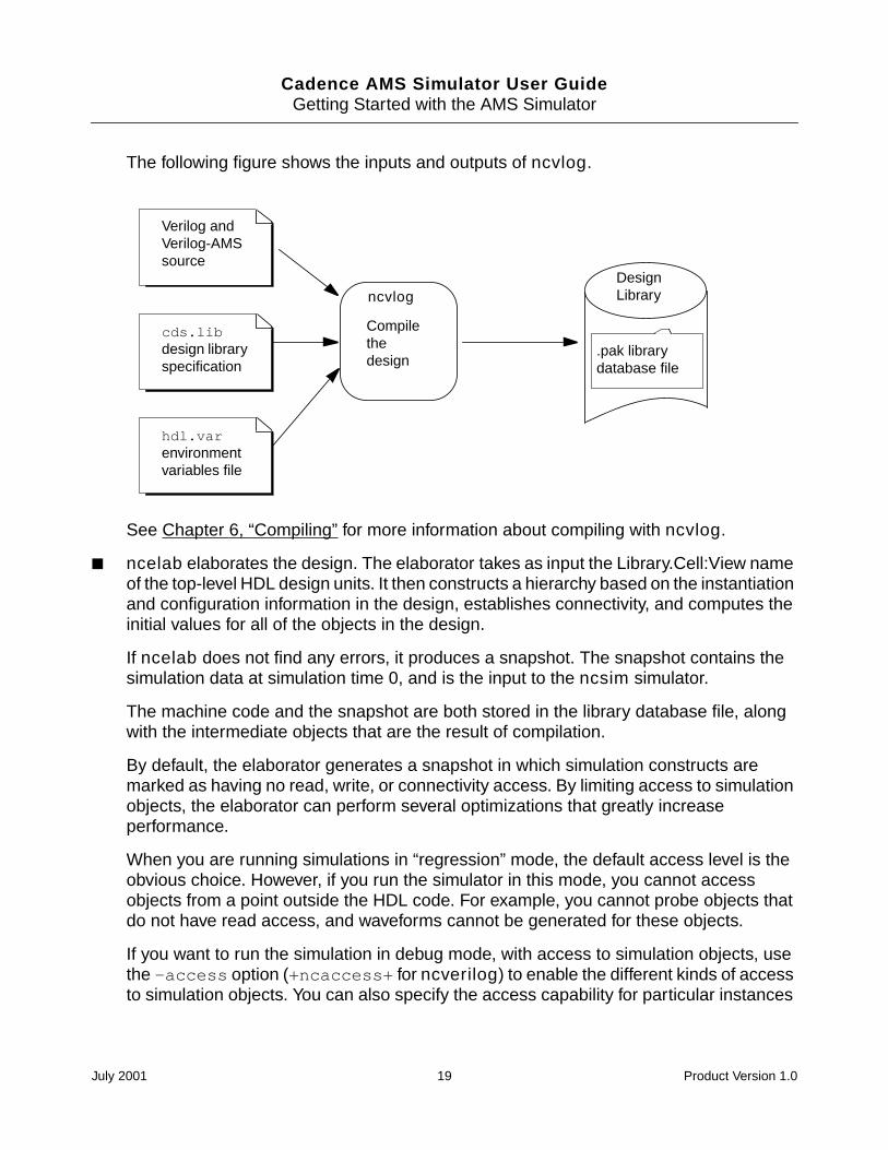
ncvlog compiles your source. This tool checks the syntax of the HDL design units(modules, macromodules, or user-defined primitives) in the input source files andgenerates an intermediate representation for each HDL design unit. These intermediaterepresentations are stored in a single file contained in the library directory. This librarydatabase file is called:
inca.architecture.lib_version.pak
For example, the name of the library database file might be something like the following:
inca.sun4v.091.pak
See “Understanding the Simulator Library Databases” on page 24 for more informationon library databases.
In the single-step startup method, ncvlog creates a binding list that the elaborator uses,and any change that you make to a source file causes that binding list to be regenerated.
July 2001 18 Product Version 1.0
Cadence AMS Simulator User GuideGetting Started with the AMS Simulator
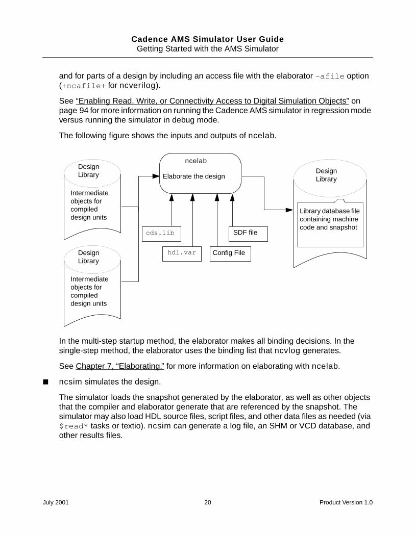
The following figure shows the inputs and outputs of ncvlog.
See Chapter 6, “Compiling” for more information about compiling with ncvlog.
ncelab elaborates the design. The elaborator takes as input the Library.Cell:View nameof the top-level HDL design units. It then constructs a hierarchy based on the instantiationand configuration information in the design, establishes connectivity, and computes theinitial values for all of the objects in the design.
If ncelab does not find any errors, it produces a snapshot. The snapshot contains thesimulation data at simulation time 0, and is the input to the ncsim simulator.
The machine code and the snapshot are both stored in the library database file, alongwith the intermediate objects that are the result of compilation.
By default, the elaborator generates a snapshot in which simulation constructs aremarked as having no read, write, or connectivity access. By limiting access to simulationobjects, the elaborator can perform several optimizations that greatly increaseperformance.
When you are running simulations in “regression” mode, the default access level is theobvious choice. However, if you run the simulator in this mode, you cannot accessobjects from a point outside the HDL code. For example, you cannot probe objects thatdo not have read access, and waveforms cannot be generated for these objects.
If you want to run the simulation in debug mode, with access to simulation objects, usethe -access option (+ncaccess+ for ncverilog) to enable the different kinds of accessto simulation objects. You can also specify the access capability for particular instances
Verilog andVerilog-AMSsource
cds.libdesign libraryspecification
hdl.varenvironmentvariables file
ncvlog
Compilethedesign
.pak librarydatabase file
DesignLibrary
July 2001 19 Product Version 1.0
Cadence AMS Simulator User GuideGetting Started with the AMS Simulator
and for parts of a design by including an access file with the elaborator -afile option(+ncafile+ for ncverilog).
See “Enabling Read, Write, or Connectivity Access to Digital Simulation Objects” onpage 94 for more information on running the Cadence AMS simulator in regression modeversus running the simulator in debug mode.
The following figure shows the inputs and outputs of ncelab.
In the multi-step startup method, the elaborator makes all binding decisions. In thesingle-step method, the elaborator uses the binding list that ncvlog generates.
See Chapter 7, “Elaborating,” for more information on elaborating with ncelab.
ncsim simulates the design.
The simulator loads the snapshot generated by the elaborator, as well as other objectsthat the compiler and elaborator generate that are referenced by the snapshot. Thesimulator may also load HDL source files, script files, and other data files as needed (via$read* tasks or textio). ncsim can generate a log file, an SHM or VCD database, andother results files.
Elaborate the design
ncelab
SDF file
Intermediateobjects forcompileddesign units
DesignLibrary
Intermediateobjects forcompileddesign units
DesignLibrary
cds.lib
hdl.var
Library database filecontaining machinecode and snapshot
DesignLibrary
Config File
July 2001 20 Product Version 1.0
Cadence AMS Simulator User GuideGetting Started with the AMS Simulator
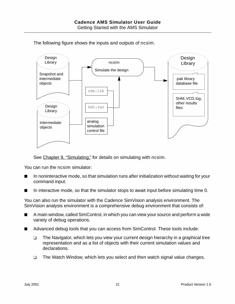
The following figure shows the inputs and outputs of ncsim.
See Chapter 9, “Simulating,” for details on simulating with ncsim.
You can run the ncsim simulator:
In noninteractive mode, so that simulation runs after initialization without waiting for yourcommand input.
In interactive mode, so that the simulator stops to await input before simulating time 0.
You can also run the simulator with the Cadence SimVision analysis environment. TheSimVision analysis environment is a comprehensive debug environment that consists of:
A main window, called SimControl, in which you can view your source and perform a widevariety of debug operations.
Advanced debug tools that you can access from SimControl. These tools include:
The Navigator, which lets you view your current design hierarchy in a graphical treerepresentation and as a list of objects with their current simulation values anddeclarations.
The Watch Window, which lets you select and then watch signal value changes.
ncsim
Simulate the design
cds.lib
hdl.var
DesignLibrary
.pak librarydatabase file
SHM, VCD, log,other resultsfiles
Snapshot andintermediateobjects
DesignLibrary
Intermediateobjects
DesignLibrary
analogsimulationcontrol file
July 2001 21 Product Version 1.0
Cadence AMS Simulator User GuideGetting Started with the AMS Simulator
The Signal Flow Browser, which lets you trace backwards through a design from asignal that has a questionable value to where a signal first diverges from theexpected behavior.
The SimVision analysis environment also includes Signalscan waves, a waveform displaytool, and Comparescan, a tool that lets you compare results stored in SHM (SST2) or VCDdatabases.
See the Affirma SimVision Analysis Environment User Guide for details on using theSimVision analysis environment.
Because the Cadence AMS simulator is a compiled code simulator that does not contain aninterpreter, and because ncsim must be able to display and manipulate mixed-languageconstructs, you cannot enter Verilog or Verilog-AMS commands at the command-line prompt.Instead, the AMS simulator supports a set of Tool Command Language (Tcl) commands forinteractive debugging. See Appendix B, “Tcl-Based Debugging,” for a list of interactivecommands.
Note: If you run ncelab in the default (regression) mode to elaborate the design, simulationobjects are tagged as having no read, write, or connectivity access. A warning or errormessage displays if you execute a Tcl command that requires read or write access. See“Enabling Read, Write, or Connectivity Access to Digital Simulation Objects” on page 94 formore information.
You can use Tk with the AMS simulator. Tk is a toolkit for the X Windows System that extendsthe Tcl facilities with commands that you can use to build user interfaces, so that you candevelop Motif-like user interfaces by writing Tcl scripts instead of writing C code. Tk is notshipped with the simulator. However, the required shared library and the library of Tcl scriptfiles is available on the internet. See Appendix A, “Enabling Tk in the NC Verilog Simulator,”for instructions on enabling Tk in the NC Verilog simulator.
Running ncverilog with a Single Step
The single-step startup method is intended primarily for Verilog-XL users who want toimprove the simulation performance of designs that are already working in a Verilog-XLenvironment and for those users who need to switch back and forth between the twosimulators.
ncverilog lets you run the Cadence AMS simulator in the same way that you run Verilog-XL.You run the simulator with a single command, ncverilog. The command-line options andarguments are the same options and arguments that you pass to Verilog-XL. For example, ifyou run Verilog-XL with the following command:
% verilog -f verilog.args
July 2001 22 Product Version 1.0
Cadence AMS Simulator User GuideGetting Started with the AMS Simulator
You run the Cadence AMS simulator with the following command, where the +ncams optiontells the simulator that the modules contain Verilog-AMS code.
% ncverilog +ncams -f verilog.args
Besides Verilog-XL command-line options, you can also include ncvlog, ncelab, and ncsimoptions on the ncverilog command line in the form of plus options. There are also someplus options that are specific to the ncverilog command.
Running the simulator with the ncverilog command automatically creates everything youneed to run the simulator, including all directories, libraries, a cds.lib file, and an hdl.varfile. The simulator then translates all applicable Verilog-XL options into options for theCadence AMS simulator and then runs the compiler (ncvlog), the elaborator (ncelab), andthe simulator (ncsim) sequentially to simulate the design.
Running the Cadence AMS simulator with the ncverilog command is recommended fordesigns that are already working in a Verilog-XL environment and for designers coming froma Verilog-XL background. The three primary reasons for this recommendation are:
Convenience. The ncverilog use model matches that of Verilog-XL. You can use thesame command files and command-line arguments for both simulators. This becomesespecially important if you need to switch back and forth between the two simulators.
Ease of use. No setup is required for single-step startup. All you do is run the tool and itsoptions on the source files. Using ncverilog improves the simulation performance ofdesigns that are already working in your Verilog-XL environment without requiring you tomodify your simulation work flow or design environment. This use model also lets youevaluate the Cadence AMS simulator using an existing design that simulates in Verilog-XL.
Search order. ncverilog mimics the search order of Verilog-XL when it binds instances.The single-step startup method understands -y and -v technology libraries andmanages them within the parser, as does Verilog-XL. ncverilog uses the same librarysearch order that Verilog-XL uses, duplicates the binding rules of Verilog-XL, andpropagates macros the same way that Verilog-XL does.
See “Running With the ncverilog Command” on page 26 for more information on ncverilog.
Running the Simulator Using Multiple Steps
You can run the Cadence AMS simulator by executing the three main tools in succession.Each tool is run with its own command line and arguments.
July 2001 23 Product Version 1.0
Cadence AMS Simulator User GuideGetting Started with the AMS Simulator
A library definition file (cds.lib) is required and a tool environment variables file (hdl.var)is recommended. While rudimentary cds.lib and hdl.var files can be used, these filesare the main means of manipulating the environment and can become quite complex.
Using multiple steps to run the AMS simulator is recommended for designs that are organizedin a library-based system. In contrast, some simulators, such as Verilog-XL, use a file-basedsystem. Multiple steps should also be used if you do not depend on being able to switch backand forth between the Cadence AMS simulator and Verilog-XL.
The multi-step startup method:
Provides more flexibility and more control over the placement and reuse of intermediatefiles.
Uses a simpler set of binding rules than those used in single-step startup, whichreproduces the Verilog-XL binding mechanism. Binding is more predictable andmanageable. For more information about binding, see “How Modules and UDPs AreResolved During Elaboration” on page 93.
Provides finer control over the update mechanisms.
Provides better incremental recompile performance for designs that continually rescan adirectory or several directories or files. This behavior is eliminated if the design isorganized in a library-based system, and is therefore much more efficient.
Understanding the Simulator Library Databases
When you compile and elaborate a design, all intermediate objects are stored in a single filein the design library. This library database file is called:
inca.architecture.lib_version.pak
For example, the name of the library database file might look like the following:
inca.sun4v.091.pak
Library database files are read/write by default. You can use the ncpack utility to change theproperties of a database to make it read-only or add-only.
A file locking mechanism manages multiple processes that might need to read or modify thecontents of a library at one time. If a process cannot get a required lock, the AMS simulatorissues a warning, and the process tries again a short time later. If a process cannot get a lockafter approximately one hour, the process times out and exits.
The following two messages are examples of the warning messages generated by the filelocking mechanism.
July 2001 24 Product Version 1.0
Cadence AMS Simulator User GuideGetting Started with the AMS Simulator
ncvlog: *W,DLWTLK: Waiting for a
read lock on library ’alt_max2’.
ncvhdl_cg: *W,DLWTLK: Waiting for a write lock on library ’worklib’.
In rare cases, file locking results in a deadlock in which neither process can proceed becauseit is waiting for the other process to release a lock. For example, some processes suspendedwith a Control-Z retain their locks when suspended (an ncelab process, for example). Inthese cases, you must terminate a process manually. You can use the ncpack -unlockcommand to do this.
A signal handling mechanism ensures that an unexpected event, such as a Control-C,flushes the database to the disk. However, conditions such as terminating a process withkill -9 or a power failure can corrupt a library database. In these cases, delete the librarydatabase file and rebuild.
The following example shows the message generated when the library is corrupted.
ncvlog: *F,DLPAKC: Packed library for alt_max2 iscorrupt, please remove ./alt_max2/inca.sun4v.091.pak.
Using a Configuration
A configuration is a set of rules that defines which cellviews under a top-level cell are to beconsidered part of a design for a given purpose (such as elaboration, or simulation). Theconfiguration is contained in a file that is a cellview of the top-level cell.
You can use the Hierarchy Editor to create configurations. For more information aboutconfigurations and about using the Hierarchy Editor, see the Hierarchy Editor User Guide.
To use configurations in the Cadence AMS flow, follow these guidelines.
Compile the design with the -use5x command line option and ensure that the design islocated in a Cadence library. For more information, see “ncvlog Command Syntax” onpage 73.
Use the -use5x4vhdl command line option when you elaborate the design. This optionapplies configurations to VHDL as well as Verilog-AMS modules. For more information,see “-USe5x4vhdl Option” on page 91.
Be aware that, by default, ncelab places the simulation snapshot in the cellviewdirectory of the first design unit specified on the ncelab command line. If this behavioris not what you need, then use the -snapshot option to specify a different location. Formore information, see “ncelab Command Syntax and Options” on page 83.
July 2001 25 Product Version 1.0
Cadence AMS Simulator User Guide
2Running With the ncverilog Command
This chapter contains the following sections:
Overview on page 27
How ncverilog Works on page 29
ncverilog Command Syntax and Options on page 30
July 2001 26 Product Version 1.0
Cadence AMS Simulator User GuideRunning With the ncverilog Command
Overview
You can run the Cadence AMS simulator by issuing one command, the ncverilogcommand. This command runs the ncvlog compiler, the ncelab elaborator, and the ncsimsimulator. This single-step startup method is intended primarily for Verilog-XL users who wantto improve the simulation performance of designs that already work in an XL environment andfor those who need to switch back and forth between the two simulators.
To use the single-step approach, you type the ncverilog command using Verilog-XLcommand-line arguments. For example, if you run Verilog-XL with an arguments file thatcontains all dash (-) and plus (+) options and all source files, as follows:
% verilog -f verilog.args
Then, to use the ncverilog command with the same arguments file, you type:
% ncverilog -f verilog.args
If your design consists of Verilog-AMS modules, rather than legacy Verilog modules, you usea command like this.
% ncverilog +ncams -f verilog.args
Besides Verilog-XL command-line options, you can include ncvlog, ncelab, and ncsimoptions on the ncverilog command line. These tools, if run separately, take dash optionsof the form -option. Many of these options have a corresponding plus option that you canuse on the ncverilog command. All of these options begin with +nc. For example, thencvlog -ieee1364 option has a corresponding ncverilog +ncieee1364 option. Seethe “Plus Options for NC Verilog Tools” section, in the “Running NC Verilog With the ncverilogCommand” chapter of the Affirma NC Verilog Simulator Help for a list of these options.
There are also some plus options that are specific to the ncverilog command. For moreinformation on these options, see the “ncverilog Command Options” section, in the “RunningNC Verilog With the ncverilog Command” chapter of the Affirma NC Verilog SimulatorHelp.
Running the ncverilog command automatically creates everything you need to run theCadence AMS simulator, including all directories, libraries, a cds.lib file, and an hdl.varfile, if they don’t already exist. The ncverilog command translates all applicable Verilog-XLoptions and runs ncvlog, ncelab, and ncsim sequentially to simulate the design.
The ncverilog command uses the same library search order that Verilog-XL uses,duplicates the binding rules of XL, and propagates macros the same way that XL does.
By default, running ncverilog runs the parser with the -update option. This optionminimizes compile time and maximizes reuse of previously compiled objects. Do not use the-update option after changing the primitive table file because then the whole design must
July 2001 27 Product Version 1.0
Cadence AMS Simulator User GuideRunning With the ncverilog Command
be re-elaborated. For information about the primitive table file, see “Creating an AnalogPrimitive Table” on page 63.
By default, the elaborator generates a snapshot with simulation objects marked as having noread, write, or connectivity access. This increases the performance of the simulator for longregression test runs, but does not provide the access to objects that you need to debug adesign. There are several ncverilog command-line options you can use to specify accessto simulation objects:
+debug. This option, which does not apply to analog objects, turns on read access to alldigital objects in the design. Read access is required for probing nets, regs and variables[including setting programming language interface (PLI) callbacks] and getting the valueof these objects. The ncverilog +debug option translates to the ncelab -access+r option.
+ncaccess+. This option selectively turns on different kinds of access. Using+ncaccess+ allows you to be specific about the types of access you need for yourdebugging purposes. For example, if you need read access turned on so that thesimulator can dump waveforms, you can specify read access only by using+ncaccess+r. If you need write access to objects so that you can deposit and forcevalues, you can specify read and write access by using +ncaccess+r+w.
+ncafile+access_file. This option specifies an access file, which lets you set thevisibility access for particular instances or portions of a design.
You can use the +ncgenafile+access_filename option to automatically generate anaccess file and then use the +ncafile+ option in a subsequent run to use the accessfile.
See “Enabling Read, Write, or Connectivity Access to Simulation Objects” on page 70 formore information on specifying access to simulation objects.
If you want to queue simulation jobs so that they run when licenses become available, makesure that the XL arguments file contains one of the license queueing options (+licq*). AnyXL +licq* option automatically translates to the Cadence AMS simulator license queueingoption (ncsim -licqueue).
ncverilog command-line options can be specified in an hdl.var file with theNCVERILOGOPTS variable.
The Cadence AMS simulator command language is based on Tcl. You cannot use the -ioption to specify an input file containing Verilog commands. To specify an input file containingTcl commands, use the +ncinput+filename or +tcl+filename option.
See Appendix B, “Tcl-Based Debugging,” for information on the Tcl commands.
July 2001 28 Product Version 1.0
Cadence AMS Simulator User GuideRunning With the ncverilog Command
How ncverilog Works
This section summarizes what the ncverilog command does. The explanation assumesthat you just substitute the ncverilog command for the verilog command to run thesimulation.
The first time you run the Cadence AMS simulator with the ncverilog command, it:
1. Creates a directory called INCA_libs.
2. Creates a work library called INCA_libs/worklib.
3. Creates a subdirectory called INCA_libs/snap.nc. The Cadence AMS simulatoruses this directory as a scratch area to create files and pass them between tools.
4. Creates a file called ncverilog.args in the snap.nc directory. This file contains allof the command-line options that were used when you started ncverilog.
5. Parses the command line. ncverilog uses the Verilog-XL command-line parser todetermine the search order of your directory structure.
6. Creates library directories for any libraries specified with -y or -v options.
7. Creates a cds.lib and hdl.var file in the INCA_libs directory.
8. Maps the ncverilog command-line options into separate options for ncvlog, ncelab,and ncsim.
9. Runs the three tools sequentially. If any tool fails, the next tool does not run. All toolsshare a common log file named ncverilog.log.
Design units contained in design files (those files specified directly on the command line)compile into the work library, which defaults to worklib.
Design units in library files (files brought in via a -y or -v option or with the ‘uselibcompiler directive) compile into a library with the same name. For example, the followingcommand specifies that top.v, models/and2.v, and models/or2.v are to compileinto a library called worklib. Design units in ./libs, which is included via the -yoption, are to compile into a library called libs.
% ncverilog top.v -y ./libs models/and2.v models/or2.v +libext+.v
Note: If you write your own hdl.var file and define the LIB_MAP variable to control thelibraries that design units compile into, the ncverilog command ignores the variable.Instead, design units in files specified directly on the command line compile into the worklibrary, and design units specified in -y libraries or -v library files compile into librariesthat have the same names.
July 2001 29 Product Version 1.0
Cadence AMS Simulator User GuideRunning With the ncverilog Command
When ncvlog completes successfully, it creates a cds.lib and an hdl.var file in thesnap.nc directory. These files contain include statements for the cds.lib andhdl.var files created during parsing. These files are passed to ncelab and ncsim.
10. Writes the SNAPSHOT variable to the hdl.var file in the snap.nc directory to store thename of the snapshot used in this run.
The next time you run ncverilog, it compares the current set of command-line options tothe options stored in the ncverilog.args file. All of the plus options and dash options mustbe the same and in the same order for the options to be evaluated as equal.
Note: Some options, such as +gui and -s, which affect only run-time behavior, are notconsidered in the comparison.
If the options are not the same, the ncverilog command creates a new ncverilog.argsfile, translates the options, and starts the tools.
If the command-line arguments are the same, the ncverilog command:
1. Reads in the cds.lib and hdl.var files in the snap.nc directory. ncverilog usesthe SNAPSHOT variable in the hdl.var file to determine what snapshot was created thelast time this directory was used.
2. Determines if all source and intermediate objects are up-to-date.
If the snapshot is up-to-date, ncsim runs directly without first running ncvlog or ncelab.If only a standard delay format (SDF) file has changed, only ncelab and ncsim arerestarted.
If the snapshot is not up-to-date, all three tools run. ncvlog runs with the -update optionby default. Only design units that have changed are recompiled.
ncverilog Command Syntax and Options
This section briefly describes the syntax and ncverilog options for the ncverilogcommand. As the syntax shows, you can also use Verilog-XL options with the ncverilogcommand. For additional information, see the “Running NC Verilog With the ncverilogCommand” chapter, in the Affirma NC Verilog Simulator Help.
ncverilog verilog-xl_arguments [ ncverilog_options ]
July 2001 30 Product Version 1.0
Cadence AMS Simulator User GuideRunning With the ncverilog Command
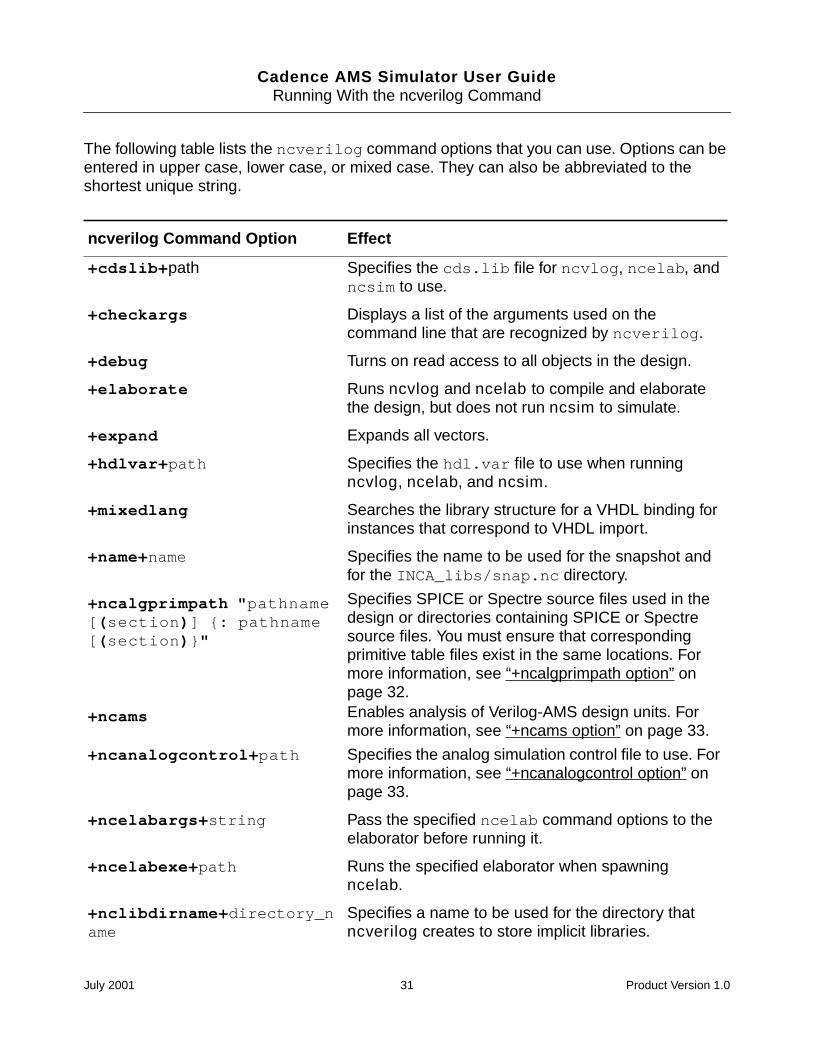
The following table lists the ncverilog command options that you can use. Options can beentered in upper case, lower case, or mixed case. They can also be abbreviated to theshortest unique string.
ncverilog Command Option Effect
+cdslib+path Specifies the cds.lib file for ncvlog, ncelab, andncsim to use.
+checkargs Displays a list of the arguments used on thecommand line that are recognized by ncverilog.
+debug Turns on read access to all objects in the design.
+elaborate Runs ncvlog and ncelab to compile and elaboratethe design, but does not run ncsim to simulate.
+expand Expands all vectors.
+hdlvar+path Specifies the hdl.var file to use when runningncvlog, ncelab, and ncsim.
+mixedlang Searches the library structure for a VHDL binding forinstances that correspond to VHDL import.
+name+name Specifies the name to be used for the snapshot andfor the INCA_libs/snap.nc directory.
+ncalgprimpath "pathname[(section)] : pathname[(section)"
Specifies SPICE or Spectre source files used in thedesign or directories containing SPICE or Spectresource files. You must ensure that correspondingprimitive table files exist in the same locations. Formore information, see “+ncalgprimpath option” onpage 32.
+ncams Enables analysis of Verilog-AMS design units. Formore information, see “+ncams option” on page 33.
+ncanalogcontrol+path Specifies the analog simulation control file to use. Formore information, see “+ncanalogcontrol option” onpage 33.
+ncelabargs+string Pass the specified ncelab command options to theelaborator before running it.
+ncelabexe+path Runs the specified elaborator when spawningncelab.
+nclibdirname+directory_name
Specifies a name to be used for the directory thatncverilog creates to store implicit libraries.
July 2001 31 Product Version 1.0
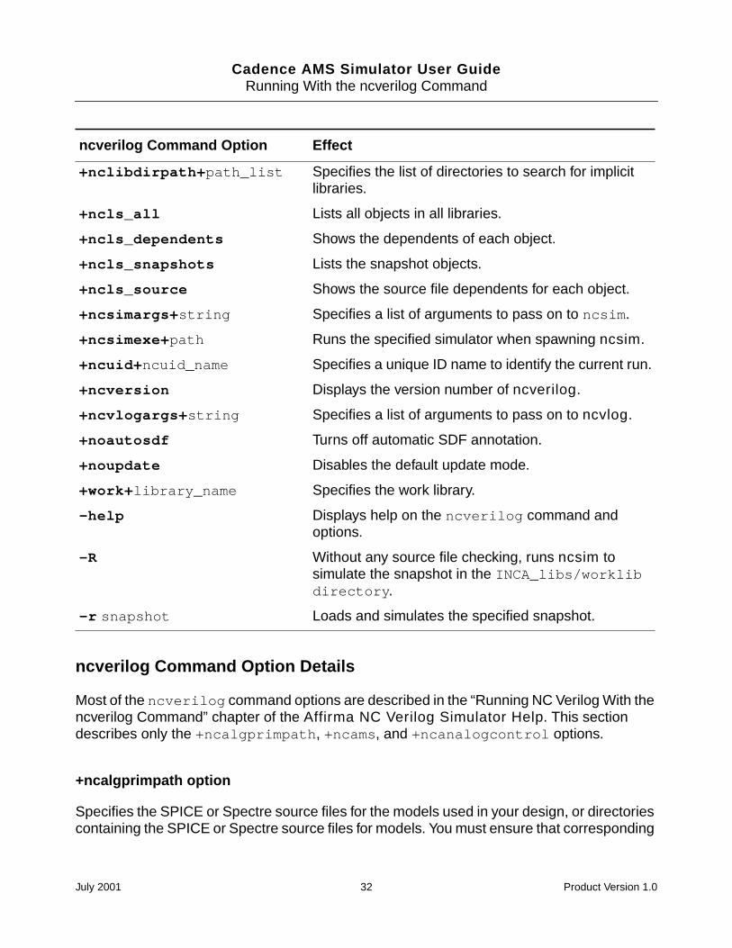
Cadence AMS Simulator User GuideRunning With the ncverilog Command
ncverilog Command Option Details
Most of the ncverilog command options are described in the “Running NC Verilog With thencverilog Command” chapter of the Affirma NC Verilog Simulator Help. This sectiondescribes only the +ncalgprimpath, +ncams, and +ncanalogcontrol options.
+ncalgprimpath option
Specifies the SPICE or Spectre source files for the models used in your design, or directoriescontaining the SPICE or Spectre source files for models. You must ensure that corresponding
+nclibdirpath+path_list Specifies the list of directories to search for implicitlibraries.
+ncls_all Lists all objects in all libraries.
+ncls_dependents Shows the dependents of each object.
+ncls_snapshots Lists the snapshot objects.
+ncls_source Shows the source file dependents for each object.
+ncsimargs+string Specifies a list of arguments to pass on to ncsim.
+ncsimexe+path Runs the specified simulator when spawning ncsim.
+ncuid+ncuid_name Specifies a unique ID name to identify the current run.
+ncversion Displays the version number of ncverilog.
+ncvlogargs+string Specifies a list of arguments to pass on to ncvlog.
+noautosdf Turns off automatic SDF annotation.
+noupdate Disables the default update mode.
+work+library_name Specifies the work library.
-help Displays help on the ncverilog command andoptions.
-R Without any source file checking, runs ncsim tosimulate the snapshot in the INCA_libs/worklibdirectory.
-r snapshot Loads and simulates the specified snapshot.
ncverilog Command Option Effect
July 2001 32 Product Version 1.0
Cadence AMS Simulator User GuideRunning With the ncverilog Command
primitive table files (with the extension .apt) exist in the same locations. ncvlog and ncelabuse the primitive table files to determine which primitives to load.
You can also achieve the same result by defining the ALGPRIMPATH variable in the hdl.varfile. For more information, see “The hdl.var File” on page 45.
For example, assume that the file simple_cap.m contains the following Verilog-AMSdefinition. This file instantiates an analog model, my_mod_cap.
// cap model definition
simulator lang=spectreparameters base=8
model my_mod_cap capacitor c=2u tc1=1.2e-8tnom=(17 + base) w=4u l=4u cjsw=2.4e-10
The primitive table file, simple_cap.m.apt, which must be in the same directory assimple_cap.m, contains the following corresponding definition.
// primitive table file
primtableprimitive my_mod_cap;
endprimtable
You can use these definitions in a command like this one.
ncverilog +ncams +ncalgprimpath+"simple_cap.m"
You use the genalgprim utility to generate primitive table files. For more information, see“Creating an Analog Primitive Table” on page 63.
+ncams option
Enables analysis of Verilog-AMS design units. Use this option to tell ncvlog that some or allof the HDL design units are written in the Verilog-AMS language. If you do not use this option,ncvlog analyzes for the Verilog language, which is likely to result in many errors when thelanguage is actually Verilog-AMS.
For example, to compile the files ms10.v and ms12.v, which contain modules written withVerilog-AMS, you can use a command like
ncverilog +ncams ms10.v ms12.v
+ncanalogcontrol option
Specifies the analog simulation control file to use. The analog control file is an ASCII text filewritten in the Spectre control language. The contents of the file control the behavior of the
July 2001 33 Product Version 1.0
Cadence AMS Simulator User GuideRunning With the ncverilog Command
analog solver. For example, the following analog simulation control file specifies the analysisto run, the start and stop times, and which nodes to save.
saveNodes options save=alltimeDom tran stop=1m
The statements you can use in the analog simulation control file are listed in “-ANalogcontrolOption” on page 111.
For example, to compile, elaborate, and simulate a Verilog-AMS design with analogcomponents, you enter a command like
ncverilog +ncams +ncanalogcontrol+adc.scs
July 2001 34 Product Version 1.0
Cadence AMS Simulator User Guide
3Setting Up Your Environment
This chapter contains the following sections:
Overview on page 36
The Library.Cell:View Approach on page 36
The cds.lib File on page 37
The hdl.var File on page 45
The setup.loc File on page 56
Directory Structure Example on page 57
July 2001 35 Product Version 1.0
Cadence AMS Simulator User GuideSetting Up Your Environment
Overview
The ncvlog and ncvhdl compilers, which parse and analyze your Verilog-AMS and VHDLsource files, store compiled objects and other derived data in libraries that are organizedaccording to a Library.Cell:View (L.C:V) approach. See “The Library.Cell:View Approach” onpage 36.
Three configuration files help you manage your data and control the operation of the varioustools and utilities:
cds.lib
Defines your design libraries and associates logical library names with physical librarylocations. See “The cds.lib File” on page 37.
hdl.var
Defines variables that affect the behavior of tools and utilities. See “The hdl.var File” onpage 45.
setup.loc
Specifies the search order that tools and utilities use when searching for the cds.liband hdl.var files. See “The setup.loc File” on page 56.
For detailed information on the library infrastructure, refer to the Cadence ApplicationInfrastructure User Guide.
The Library.Cell:View Approach
Compiled objects and other derived data are stored in libraries. The library structure isorganized according to a Library.Cell:View (L.C:V) approach.
Library
A collection of related cells that describe components of a single design (a designlibrary) or common components used in many designs (a reference library).
Each library is referenced by a logical name and has a unique physical directoryassociated with it. You define library names and map them to physical directories in thecds.lib file.
The library used for your current design work is called the working or work library. Youdefine your current work library by setting a variable in the hdl.var file or by using the-work command-line option.
July 2001 36 Product Version 1.0
Cadence AMS Simulator User GuideSetting Up Your Environment
Cell
A cell is an object with a unique name stored in a library. Each module, macromodule,UDP, entity, architecture, package, package body, connectrules, or configuration is aunique cell.
The internal intermediate objects necessary to represent a cell are contained in thelibrary database file (.pak file) stored in the library directory.
View
A view is a version of a cell. Views can be used to delineate between representations(schematic, VHDL, Verilog-AMS), abstraction levels (behavior, RTL, postsynthesis),status (experimental, released, golden), and so on. For example, you might have oneview that is the RTL representation of a particular module and another view that is thebehavioral representation, or you might have two different versions of a cell - one withtiming and one without timing.
The internal intermediate objects necessary to represent a view are contained in thelibrary database file (.pak file) stored in the library directory.
See “Directory Structure Example” on page 57 for an example directory structure.
The cds.lib File
The cds.lib file is an ASCII text file that defines which libraries are accessible and wherethey are located. The file contains statements that map logical library names to their physicaldirectory paths. During initialization, all tools that need to understand library names read thecds.lib file and compute the logical to physical mapping.
You can create a cds.lib file with any text editor. The following examples show how librarybindings are specified in the cds.lib file with the DEFINE statement. The logical andphysical names can be the same or different.
You can have more than one cds.lib file. For example, you can have a project-widecds.lib file that contains library settings specific to a project (like technology or celllibraries) and a user cds.lib file. Use the INCLUDE or SOFTINCLUDE statements toinclude a cds.lib file within a cds.lib file.
keyword logical library name physical location
DEFINE lib_std /usr1/libs/std_lib
DEFINE worklib ../worklib
July 2001 37 Product Version 1.0
Cadence AMS Simulator User GuideSetting Up Your Environment
Note: If you are doing a pure VHDL or a mixed-language simulation, you must use theINCLUDE or SOFTINCLUDE statement in the cds.lib file to include the default cds.lib filelocated in:
your_install_directory/tools/inca/files/cds.lib
This cds.lib file contains a SOFTINCLUDE statement to include a file called cdsvhdl.lib,which defines the Synopsys IEEE libraries included in the release. If you want to use the IEEElibraries that were shipped with Version 2.1 of the NC VHDL simulator or NC simulator insteadof the Synopsys libraries, you must include the cds.lib file located inyour_install_directory/tools/inca/files/IEEE_pure/cds.lib.
By default, tools search for the cds.lib file in the following locations, which are defined inthe setup.loc file. The first cds.lib file that is found is used.
Your current directory
$CDS_WORKAREA (user work area, if defined)
$CDS_SEARCHDIR (if defined)
Your home directory
$CDS_PROJECT (project area, if defined)
$CDS_SITE (site setup, if defined)
your_install_directory/share
You can edit the setup.loc file to add other locations to search or to change the order ofprecedence to use when searching for the cds.lib file. See “The setup.loc File” onpage 56.
Each tool that reads a cds.lib file also has a -cdslib option that you can use on thecommand line to override the search order specified in the setup.loc file.
The Work Library
The library used for your current design work is called the work or working library. The worklibrary is the library into which design units are compiled. Like other libraries, the directorypath of the work library is defined in the cds.lib file.
There are several ways to specify which library is the work library. For Verilog-AMS, you canuse compiler directives in the source file, the -work command line option, or variablesdefined in the hdl.var file. See “Controlling the Compilation of Design Units intoLibrary.Cell:View” on page 80 for details. For VHDL, define the WORK variable in the hdl.varfile or use the -work option on the command line.
July 2001 38 Product Version 1.0
Cadence AMS Simulator User GuideSetting Up Your Environment
cds.lib Statements
The following list shows the statements you can use in a cds.lib file.
DEFINE lib_name path
Associates the logical library name specified with the lib_name argument with the physicaldirectory path specified with the path argument.
Examples:
DEFINE ttl_lib /usr1/libraries/ttl_lib
DEFINE ttl ./libraries/ttl
It is an error to specify the same directory in multiple library definitions.
UNDEFINE lib_name
Undefines the specified library. This command is useful for removing any libraries that weredefined in other files. No error is generated if lib_name was not previously defined.
Example:
UNDEFINE ttl
INCLUDE file
Reads the specified file as a cds.lib file. Use INCLUDE to include the library definitionscontained in the specified file. An error message is printed if file is not found or if recursionis detected.
The file to be included does not have to be named cds.lib.
The following example includes the cds.lib file in /users/$USER:
INCLUDE /users/$USER/cds.lib
SOFTINCLUDE file
SOFTINCLUDE is the same as the INCLUDE statement, except that no error messages areprinted if the file does not exist. Using SOFTINCLUDE to cause recursion results in an error.
The following example includes the cds.lib file in the $GOLDEN directory:
SOFTINCLUDE $GOLDEN/cds.lib
July 2001 39 Product Version 1.0
Cadence AMS Simulator User GuideSetting Up Your Environment
ASSIGN lib attribute path
Assigns an attribute to the library.
See “Binding One Library to Multiple Directories” on page 42 for more details.
Note: TMP is the only attribute that is supported.
The following example defines the iclib library and assigns the attribute TMP to the librarydefined as iclib. The value of TMP is ./ic_tmp_lib.
DEFINE iclib ./ic_lib
ASSIGN iclib TMP ./ic_tmp_lib
UNASSIGN lib attribute
Removes an assigned attribute from the library.
No error is generated if the attribute has not been assigned to the library. If the library has notbeen defined, an error is generated.
Note: TMP is the only attribute that is supported.
Example:
UNASSIGN iclib TMP
cds.lib Syntax Rules
The following rules apply to the cds.lib file:
Only one statement per line is allowed.
Blank lines are allowed.
Use the pound sign (#) or the double hyphen ( -- ) to begin a comment. You mustprecede and follow the comment character with white space, a tab, or a new line.
Examples:
# this is a comment
-- this is another comment.
Keywords are identified as the first non-whitespace string on a line.
Keywords and attributes are case insensitive.
July 2001 40 Product Version 1.0
Cadence AMS Simulator User GuideSetting Up Your Environment
You can include symbolic variables (UNIX environment variables like $HOME and CSHextensions such as ~ and ~user).
Symbolic variables and library path names are in the file system domain and are casesensitive.
You can enter absolute or relative file paths. Relative paths are relative to the location ofthe file in which they occur, not to the directory where the tool was invoked.
Library names and path names reside within the file system name-space. ForVerilog-AMS, nonescaped library names are the same as the Verilog-AMS name; forVHDL, nonescaped library names are resolved to lower-case.
You cannot directly use escaped library names in a cds.lib file. To use an escapedname, run the nmp program in the install_directory/tools/bin directory tosee how escaped library names are mapped to file system names. Then use the mappedname in the cds.lib file.
The syntax for the nmp program is as follows. Note the trailing space afterillegal_name.
% nmp mapName Verilog | NVerilog | Vhdl Filesys ‘\illegal_name ’
For example, to use the library named Lib*, you must use the library’s escaped nameformat (\Lib*), because “*” is an illegal character. To determine the mapped file systemname for \Lib*, type:
% nmp mapName Verilog Filesys ‘\Lib* ’
The nmp program returns:
Lib#2a
Use the mapped name (Lib#2a) in the cds.lib file.
July 2001 41 Product Version 1.0
Cadence AMS Simulator User GuideSetting Up Your Environment
Example cds.lib File
The following example contains many of the statements you can use in a cds.lib file.Comments begin with the pound sign ( # ). See “cds.lib Statements” on page 39 for adescription of the cds.lib statements.
# Assign /usr1/libraries/ic_library to the# logical library name ic_libDEFINE ic_lib /usr1/libraries/ic_library
# Specify a relative path to library aludesign.# The path is relative to this cds.lib fileDEFINE aludesign ./design
# Read cds.lib from the /users/$USERS directory.INCLUDE /users/$USER/cds.lib
# Read cds.lib from the $CADLIBS directory.SOFTINCLUDE $CADLIBS/cds.lib
# Define a temporary directory and assign the TMP attribute# to it. The directory ./temp must exist and templib must be# set to WORK in the hdl.var file in order to compile data# into it.DEFINE templib ./temp_libASSIGN templib TMP ./temp
Binding One Library to Multiple Directories
You can bind a previously defined library to a temporary storage directory by using the TMPattribute with the ASSIGN keyword. This allows multiple designers to reference a commonlibrary, but store compiled objects in separate design directories. When the TMP attribute isapplied to a library, a logical OR operation is performed to include the files present in both themaster and TMP directories.
Use the UNASSIGN statement to remove the TMP attribute before compiling your design unitsinto the master library.
The following steps assign the attribute TMP to the library lsttl (the environment variablePROJECT is set to /usr1/libs). Subsequent calls to lsttl include the contents of boththe library (lsttl) and the directory (/usr1/work/lsttl_design).
1. Set the environment variable at the command-line prompt.
% setenv PROJECT /usr1/libs
2. Set the cds.lib file variables.
# Define the master library directory
DEFINE lsttl $PROJECT/lsttl_lib
# Assign a temp storage directory
ASSIGN lsttl TMP ~/work/lsttl_design
July 2001 42 Product Version 1.0
Cadence AMS Simulator User GuideSetting Up Your Environment
The attribute TMP is now assigned to the library lsttl. Subsequent calls to lsttl includethe contents of both the library (lsttl) and the directory (/usr1/work/lsttl_design).
Directory Binding Rules
The following rules apply to binding directories with the TMP attribute:
Only one directory can be bound to a master library using the TMP attribute.
If the referenced library does not exist when the ASSIGN command is processed, anerror is generated and the command has no effect.
The TMP attribute can be reassigned to a new value without deassigning it first.
Debugging cds.lib Files
You can use the nchelp -cdslib command to display information about the contents ofcds.lib files. This can help you identify errors and any incorrect settings contained withinyour cds.lib files.
Syntax:
% nchelp -cdslib [cds.lib_file]
Examples:
% nchelp -cdslib
% nchelp -cdslib ~/cds.lib
% nchelp -cdslib ~/design/cds.lib
The following example shows how to display information about the contents of cds.libfiles. In the example, the nchelp -cdslib command displays the contents of the
July 2001 43 Product Version 1.0
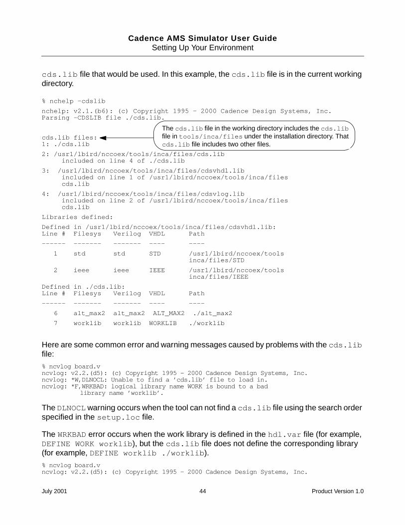
Cadence AMS Simulator User GuideSetting Up Your Environment
cds.lib file that would be used. In this example, the cds.lib file is in the current workingdirectory.
Here are some common error and warning messages caused by problems with the cds.libfile:
% ncvlog board.vncvlog: v2.2.(d5): (c) Copyright 1995 - 2000 Cadence Design Systems, Inc.ncvlog: *W,DLNOCL: Unable to find a ’cds.lib’ file to load in.ncvlog: *F,WRKBAD: logical library name WORK is bound to a bad
library name ’worklib’.
The DLNOCLwarning occurs when the tool can not find a cds.lib file using the search orderspecified in the setup.loc file.
The WRKBAD error occurs when the work library is defined in the hdl.var file (for example,DEFINE WORK worklib), but the cds.lib file does not define the corresponding library(for example, DEFINE worklib ./worklib).
% ncvlog board.vncvlog: v2.2.(d5): (c) Copyright 1995 - 2000 Cadence Design Systems, Inc.
% nchelp -cdslib
nchelp: v2.1.(b6): (c) Copyright 1995 - 2000 Cadence Design Systems, Inc.Parsing -CDSLIB file ./cds.lib.
cds.lib files:1: ./cds.lib
2: /usr1/lbird/nccoex/tools/inca/files/cds.libincluded on line 4 of ./cds.lib
3: /usr1/lbird/nccoex/tools/inca/files/cdsvhdl.libincluded on line 1 of /usr1/lbird/nccoex/tools/inca/filescds.lib
4: /usr1/lbird/nccoex/tools/inca/files/cdsvlog.libincluded on line 2 of /usr1/lbird/nccoex/tools/inca/filescds.lib
Libraries defined:
Defined in /usr1/lbird/nccoex/tools/inca/files/cdsvhdl.lib:Line # Filesys Verilog VHDL Path
------ ------- ------- ---- ----
1 std std STD /usr1/lbird/nccoex/toolsinca/files/STD
2 ieee ieee IEEE /usr1/lbird/nccoex/toolsinca/files/IEEE
Defined in ./cds.lib:Line # Filesys Verilog VHDL Path
------ ------- ------- ---- ----
6 alt_max2 alt_max2 ALT_MAX2 ./alt_max2
7 worklib worklib WORKLIB ./worklib
The cds.lib file in the working directory includes the cds.libfile in tools/inca/files under the installation directory. Thatcds.lib file includes two other files.
July 2001 44 Product Version 1.0
Cadence AMS Simulator User GuideSetting Up Your Environment
ncvlog: *W,DLCPTH: cds.lib Invalid path ’/usr1/clinton/inca/board/worklib’on line 7 of ./cds.lib (cds.lib command ignored).
The DLCPTH warning occurs when the directory path specified in the cds.lib file does notexist or is inaccessible. For example, you might have the following line in your cds.lib file,but you have not created a ./worklib physical directory.
DEFINE worklib ./worklib
The hdl.var File
The hdl.var file is an ASCII text file that contains:
Configuration variables, which determine how your design environment is configured.These include:
Variables that you can use to specify the work library where the compiler storescompiled objects and other derived data. For Verilog-AMS, you can use theLIB_MAP or WORK variables. For VHDL, use the WORK variable.
For Verilog-AMS, variables (LIB_MAP, VIEW_MAP, WORK) that you can use to specifythe libraries and views to search when the elaborator resolves instances.
Variables that allow you to define compiler, elaborator, and simulator command-lineoptions and arguments.
Variables that specify the locations of support files and invocation scripts.
For information about the syntax rules that apply to the hdl.var file, see “hdl.var SyntaxRules” on page 53.
You can have more than one hdl.var file. For example, you can have a project hdl.varfile that contains variable settings used to support all your projects and local hdl.var files,located in specific design directories, that contain variable settings specific to each project,such as the setting for the WORK variable.
By default, tools search for the hdl.var file in the following locations, which are defined inthe setup.loc file. The first hdl.var file that is found is used.
July 2001 45 Product Version 1.0
Cadence AMS Simulator User GuideSetting Up Your Environment
Your current directory
$CDS_WORKAREA (user work area, if defined)
$CDS_SEARCHDIR (if defined)
Your home directory
$CDS_PROJECT (project area, if defined)
$CDS_SITE (site setup, if defined)
your_install_directory/share
You can edit the setup.loc file to add other locations to search or to change the order ofprecedence to use when searching for the hdl.var file. See “The setup.loc File” on page 56.
Each tool that reads a hdl.var file also has a -hdlvar option that you can use on thecommand line to override the search order specified in the setup.loc file.
hdl.var Statements
The following list shows the statements you can use in an hdl.var file. Variable is analphanumeric variable name. Value is optional; if provided, it is either scalar or a list. See“hdl.var Variables” on page 47 for a list of hdl.var variables.
Note: The variable definitions in the hdl.var file are treated as literal strings. Do not usequotation marks in the definitions unless you explicitly want them as part of the input. Forexample, use:
DEFINE NCVLOGOPTS -define foo=16’h03
instead of
DEFINE NCVLOGOPTS -define foo="16’h03"
which is the same as typing:
% ncvlog -define foo=\"16’h03\"
DEFINE variable value
Defines a variable and assigns a value to the variable.
The following example defines the variable WORK to be worklib.
DEFINE WORK worklib
The following example defines VERILOG_SUFFIX as the list .v, .vg, and .vb.
July 2001 46 Product Version 1.0
Cadence AMS Simulator User GuideSetting Up Your Environment
DEFINE VERILOG_SUFFIX (.v, .vg, .vb)
The following example defines the variable NCVHDLOPTS, which is used to specify command-line options for the ncvhdl compiler.
DEFINE NCVHDLOPTS -messages -errormax 10
UNDEFINE variable
Causes variable to become undefined. This statement is useful for removing definitionsdefined in other files. If variable was not previously defined, you do not get an errormessage.
UNDEFINE NCUSE5X
INCLUDE filename
Reads filename as an hdl.var file.
Use INCLUDE to include the variable definitions contained in the specified file. The pathnamecan be absolute or relative. If it is relative, it is relative to the hdl.var file in which it isdefined.
Examples:
INCLUDE ~/my_hdl.var
INCLUDE /users/$USER/hdl.var
If the file is not found, a warning message is printed.
SOFTINCLUDE filename
SOFTINCLUDE is the same as the INCLUDE statement, except that no warning message isprinted if the specified file cannot be found.
Examples:
SOFTINCLUDE ~/hdl.var
SOFTINCLUDE $GOLDEN/hdl.var
hdl.var Variables
The following list shows the variables you can use in an hdl.var file.
July 2001 47 Product Version 1.0
Cadence AMS Simulator User GuideSetting Up Your Environment
ALGPRIMPATH
Specifies the SPICE or Spectre source files for the models used in your design, or directoriescontaining the SPICE or Spectre source files for models. You must ensure that correspondingprimitive table files (with the extension .apt) exist in the same locations. ncvlog and ncelabuse the primitive table files to determine which primitives to load.
You can also achieve the same result by using the -ncalgprimpath option with thencverilog command and the -algprimpath option with the ncvlog, and ncelabcommands.
For example, assume that the file, simple_cap.m, contains the following Verilog-AMSdefinition. This file instantiates an analog model, my_mod_cap.
// cap model definition
simulator lang=spectreparameters base=8
model my_mod_cap capacitor c=2u tc1=1.2e-8 tnom=(17 + base) w=4u l=4u cjsw=2.4e-10
The primitive table file, simple_cap.m.apt, which must be in the same directory assimple_cap.m, contains the following corresponding definition.
// primitive table file
primtableprimitive my_mod_cap;
endprimtable
You can use a statement like the following to define an hdl.var variable that uses thesedefinitions.
DEFINE ALGPRIMPATH simple_cap.m
LIB_MAP (Verilog-AMS only)
Maps files and directories to library names. Use the plus sign (+) to create a default for filesor directories that are not explicitly stated.
For ncvlog, LIB_MAP specifies that source files are to be compiled into a particular library.See “Controlling the Compilation of Design Units into Library.Cell:View” on page 80.
For ncelab, LIB_MAP specifies the list of libraries to search when resolving instances. See“How Modules and UDPs Are Resolved During Elaboration” on page 93.
Example:
DEFINE LIB_MAP (./source/lib1/... => lib1, \./design => lib2, \
July 2001 48 Product Version 1.0
Cadence AMS Simulator User GuideSetting Up Your Environment
top.v => lib3, \+ => worklib )
NCELABOPTS
Sets elaborator command-line options. Top-level design unit name(s) can also be included.
You cannot include the -logfile, -append_log, -cdslib, or -hdlvar options in thedefinition of this variable.
Example:
DEFINE NCELABOPTS -messages -errormax 10
NCHELP_DIR
Specifies the path to the directory where the help text files are located. These files are usedby nchelp to print more detailed information on the messages printed by other tools. See the“nchelp” section of the “Utilities” chapter, in the Affirma NC Verilog Simulator Help formore information.
The help files are usually located in:
install_directory/tools/inca/files/help
Use the NCHELP_DIR variable if the help files are located in another directory.
DEFINE NCHELP_DIR path_to_help_files
NCSDFCOPTS
Sets command-line options for ncsdfc. See the “ncsdfc” section of the “Utilities” chapter, inthe Affirma NC Verilog Simulator Help for more information.
Example:
DEFINE NCSDFCOPTS -messages -precision 1ps
NCSIMOPTS
Sets simulator command-line options. A snapshot name can also be included.
You cannot include the -logfile, -append_log, -cdslib, or -hdlvar options in thedefinition of this variable.
Example:
July 2001 49 Product Version 1.0
Cadence AMS Simulator User GuideSetting Up Your Environment
DEFINE NCSIMOPTS -messages -errormax 10
NCSIMRC
Executes a command file when ncsim is invoked. This command file can contain commands,such as aliases, that you use with every simulation run.
Example:
DEFINE NCSIMRC /usr/design/rcfile
NCUPDATEOPTS
Sets command-line options for ncupdate. For example, if you have compiled a newelaborator with PLI routines statically linked, ncupdateopts -ncelab specifies the pathto the new elaborator. See the “ncupdate” section of the “Utilities” chapter, in the Affirma NCVerilog Simulator Help for more information.
Example:
DEFINE NCUPDATEOPTS -ncelab ./pli/my_elab
NCUSE5X
For Verilog-AMS, causes three files to be generated when you compile Verilog-AMS sourcefile(s): master.tag, verilog.v, and pc.db. These files are required if you want to viewVerilog-AMS objects when you browse libraries using the graphical user interface. They arealso required if you plan to use a configuration for your design.
For VHDL, this variable causes the generation of a pc.db file, which is necessary if you wantto use the Hierarchy Editor.
Example:
DEFINE NCUSE5X
NCVERILOGOPTS (Verilog-AMS only)
Sets command-line options for ncverilog. ncverilog creates an hdl.var file automaticallyif one does not exist. However, if you want to set frequently-used options, or if you want to setdefaults to be used by all users, you can create an hdl.var file before running the tools, andthe tools will read this hdl.var file. Use the NCVERILOGOPTS variable to set ncverilogcommand-line options.
See Chapter 2, “Running With the ncverilog Command,” for details on ncverilog.
July 2001 50 Product Version 1.0
Cadence AMS Simulator User GuideSetting Up Your Environment
NCVHDLOPTS (VHDL only)
Sets command-line options for the ncvhdl compiler. VHDL source file names can also beincluded.
You cannot include the -logfile, -append_log, -cdslib, or -hdlvar options in thedefinition of this variable.
Example:
DEFINE NCVHDLOPTS -messages -errormax 10 -file ./proj_file
NCVLOGOPTS (Verilog-AMS only)
Sets command-line options for the ncvlog compiler. Verilog-AMS source file names can alsobe included.
You cannot include the -logfile, -append_log, -cdslib, or -hdlvar options in thedefinition of this variable.
Example:
DEFINE NCVLOGOPTS -messages -errormax 10 -file ./proj_file
SRC_ROOT
Defines an ordered list of paths to search for source files when you are updating a designeither by running ncsim -update or by rerunning ncverilog. The paths listed in thedefinition of this variable tell the NC tools where to look for source files if design units are out-of-date.
See the “SRC ROOT” section of the “Compiling Verilog Source Files with ncvlog” chapter, inthe Affirma NC Verilog Simulator Help for more information.
Example:
DEFINE SRC_ROOT (~lbird/source, $PROJECT)
VERILOG_SUFFIX (Verilog-AMS only)
Defines valid file extensions for Verilog-AMS source files.
Example:
DEFINE VERILOG_SUFFIX (.v, .vr, .vb, .vg)
July 2001 51 Product Version 1.0
Cadence AMS Simulator User GuideSetting Up Your Environment
This variable has no effect on the behavior of the Cadence AMS environment.
VHDL_SUFFIX (VHDL only)
Defines valid file extensions for VHDL source files.
Example:
DEFINE VHDL_SUFFIX (.vhd, .vhdl)
VIEW (Verilog-AMS only)
Sets the view name. See “Controlling the Compilation of Design Units into Library.Cell:View”on page 80 for details on this variable.
Example:
DEFINE VIEW behavior
VIEW_MAP (Verilog-AMS only)
Maps files and file extensions to view names.
For ncvlog, VIEW_MAP specifies that files or files with a particular extension are compiledwith a specific view name. See “Controlling the Compilation of Design Units intoLibrary.Cell:View” on page 80.
For ncelab, VIEW_MAP is used to establish the list of views to search when resolvinginstances. See “How Modules and UDPs Are Resolved During Elaboration” on page 93.
Example:
DEFINE VIEW_MAP ( .v => behav, \.rtl => rtl, \.gate => gate, \myfile.v => gate)
VXLOPTS (VHDL only)
Specifies Verilog-XL command-line options.
This variable should be used only by Leapfrog with Verilog Model Import customers who wantto import the same Verilog model into the NC simulator. This variable is used by thencxlimport utility to prepare the Verilog model for import. See ”Preparing a Leapfrog Verilog
July 2001 52 Product Version 1.0
Cadence AMS Simulator User GuideSetting Up Your Environment
Model Import Design” section of the “Mixed Verilog/VHDL Simulation” chapter in the AffirmaNC Verilog Simulator Help for details on using ncxlimport.
WORK
Defines the current work library into which HDL design units are compiled.
Example:
DEFINE WORK worklib
hdl.var Syntax Rules
The following rules apply to the hdl.var file:
Only one statement per line is allowed.
Keywords and variable names are case insensitive.
Variable values, file names, and path names are case sensitive.
Begin comments with either the pound sign ( # ) or a double hyphen (--). The commentcharacter must be either the first character in a line or preceded by white space.
You can extend a statement over more than one line by using the escape character ( \ )as the last character of the line. For example:
DEFINE ALPHA (a,\b,\c)
is the same as:
DEFINE ALPHA (a, b, c)
Left and right parentheses indicate the beginning and end of a list of values.
Use a comma to separate values in a list.
You can have a list containing zero elements.
DEFINE EMPTY_LIST ( )
Any character can be escaped using the backslash ( \ ) escape character. Charactersshould be escaped if the meaning of the character is its ASCII value. For example, thefollowing line defines the variable JUNK as \dump\.
DEFINE JUNK \\dump\\
The following example defines LIST as a, b c.
DEFINE LIST (a\,b,c)
July 2001 53 Product Version 1.0
Cadence AMS Simulator User GuideSetting Up Your Environment
You can use tilde ( ~ ) in filename or value to specify:
~ (or $HOME)
~user (home of <user>)
The “~” must be the first non-whitespace character in filename or value. Forexample:
DEFINE DIR_RELATION ~/bin != ~lbird/bin
expands to:
/usr/bin != /usr/lbird/bin
The white space preceding and following a scalar value is ignored. In the following twolines, the variable TEST has the same value (this is a test):
DEFINE TEST this is a test
DEFINE TEST this is a test
You can use the dollar sign ( $ ) in filename or value to indicate variable substitution.The syntax can be either $variable or $variable, where the left and rightbraces ( ) are real characters that mark the beginning and end of the variable name.Variable substitution first searches the hdl.var definitions and, if none are found, thensearches for environment variables.
The following example uses the environment variable $SHELL to define an hdl.varvariable:
DEFINE MY_SHELL $SHELL
In the following example, LIB_MAP is defined as:
(./source/lib1/... => lib1)
Then the variable is redefined as
(./source/lib1/... => lib1, ./design => lib2).
DEFINE LIB_MAP (./source/lib1/... => lib1)
DEFINE LIB_MAP ($LIB_MAP, ./design => lib2)
In the following example, ALPHA is defined as first. Then BETA is defined as first== one.
DEFINE ALPHA first
DEFINE BETA $alpha == one
When a scalar value or file name is specified as a relative path, the path is relative to thelocation of the hdl.var file in which it is defined.
July 2001 54 Product Version 1.0
Cadence AMS Simulator User GuideSetting Up Your Environment
Example hdl.var File
In the following example hdl.var file, the WORK variable is used to define the work libraryinto which design units are compiled. This library must be defined in the cds.lib file. Othervariables are defined to list valid file extensions for Verilog-AMS and VHDL source files andto specify command-line options for various tools.
# Define the work libraryDEFINE WORK worklib
# Define valid Verilog-AMS file extensionsDEFINE VERILOG_SUFFIX (.v, .vr, .vb, .vg)
# Define valid VHDL file extensionsDEFINE VHDL_SUFFIX (.vhd, .vhdl)
# Specify command-line options for the ncvhdl compilerDEFINE NCVHDLOPTS -messages -errormax 10
# Specify command-line options for the ncvlog compilerDEFINE NCVLOGOPTS -messages -errormax 10 -ieee1364
# Specify command-line options for the elaboratorDEFINE NCELABOPTS -messages -errormax 10 -ieee1364 -plinooptwarn
# Specify the simulation startup command fileDEFINE NCSIMRC /usr/design/simrc.cmd
Debugging hdl.var Files
You can use the nchelp -hdlvar command to display information about the contents ofhdl.var files. This can help you identify incorrect settings that may be contained within yourhdl.var files.
Syntax:
% nchelp -hdlvar [hdl.var_file]
Examples:
% nchelp -hdlvar
% nchelp -hdlvar ~/hdl.var
The following example shows how to display information about the contents of an hdl.varfile. In the example, the nchelp -hdlvar command displays the contents of the firsthdl.var file found using the search order in the setup.loc file. In this example thehdl.var file is in the current working directory.
% nchelp -hdlvar
nchelp: v2.2.(d5): (c) Copyright 1995 - 2000 Cadence Design Systems, Inc.
Parsing -HDLVAR file ./hdl.var.
hdl.var files:
1: ./hdl.var
Variables defined:
July 2001 55 Product Version 1.0
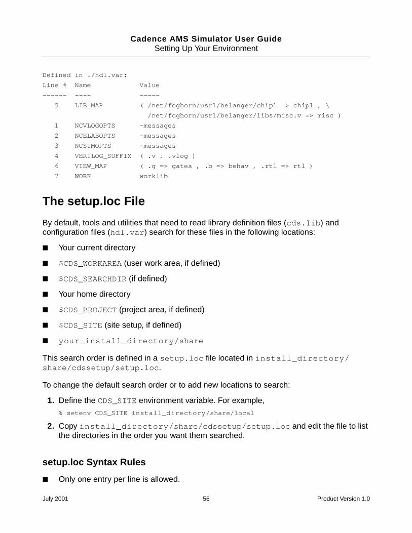
Cadence AMS Simulator User GuideSetting Up Your Environment
Defined in ./hdl.var:
Line # Name Value
------ ---- -----
5 LIB_MAP ( /net/foghorn/usr1/belanger/chip1 => chip1 , \
/net/foghorn/usr1/belanger/libs/misc.v => misc )
1 NCVLOGOPTS -messages
2 NCELABOPTS -messages
3 NCSIMOPTS -messages
4 VERILOG_SUFFIX ( .v , .vlog )
6 VIEW_MAP ( .g => gates , .b => behav , .rtl => rtl )
7 WORK worklib
The setup.loc File
By default, tools and utilities that need to read library definition files (cds.lib) andconfiguration files (hdl.var) search for these files in the following locations:
Your current directory
$CDS_WORKAREA (user work area, if defined)
$CDS_SEARCHDIR (if defined)
Your home directory
$CDS_PROJECT (project area, if defined)
$CDS_SITE (site setup, if defined)
your_install_directory/share
This search order is defined in a setup.loc file located in install_directory/share/cdssetup/setup.loc.
To change the default search order or to add new locations to search:
1. Define the CDS_SITE environment variable. For example,
% setenv CDS_SITE install_directory/share/local
2. Copy install_directory/share/cdssetup/setup.loc and edit the file to listthe directories in the order you want them searched.
setup.loc Syntax Rules
Only one entry per line is allowed.
July 2001 56 Product Version 1.0
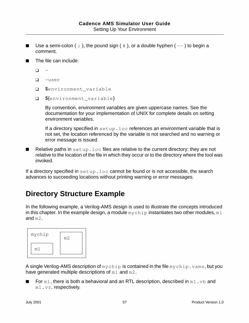
Cadence AMS Simulator User GuideSetting Up Your Environment
Use a semi-colon ( ; ), the pound sign ( # ), or a double hyphen ( -- ) to begin acomment.
The file can include:
~
~user
$environment_variable
$environment_variable
By convention, environment variables are given uppercase names. See thedocumentation for your implementation of UNIX for complete details on settingenvironment variables.
If a directory specified in setup.loc references an environment variable that isnot set, the location referenced by the variable is not searched and no warning orerror message is issued.
Relative paths in setup.loc files are relative to the current directory; they are notrelative to the location of the file in which they occur or to the directory where the tool wasinvoked.
If a directory specified in setup.loc cannot be found or is not accessible, the searchadvances to succeeding locations without printing warning or error messages.
Directory Structure Example
In the following example, a Verilog-AMS design is used to illustrate the concepts introducedin this chapter. In the example design, a module mychip instantiates two other modules, m1and m2.
A single Verilog-AMS description of mychip is contained in the file mychip.vams, but youhave generated multiple descriptions of m1 and m2.
For m1, there is both a behavioral and an RTL description, described in m1.vb andm1.vr, respectively.
mychip
m1
m2
July 2001 57 Product Version 1.0
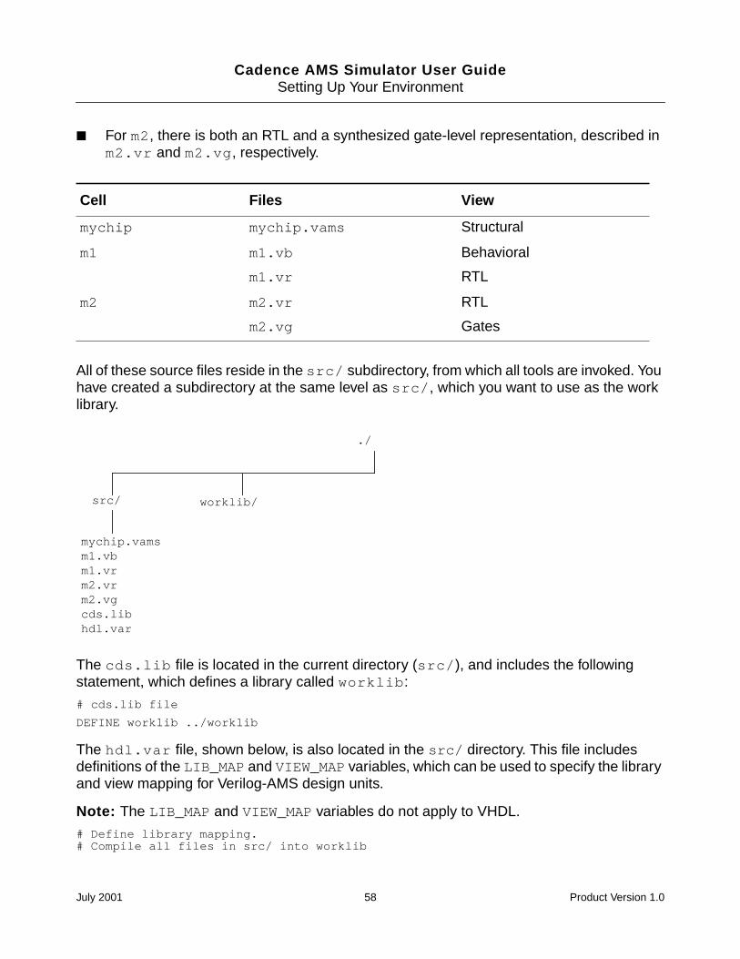
Cadence AMS Simulator User GuideSetting Up Your Environment
For m2, there is both an RTL and a synthesized gate-level representation, described inm2.vr and m2.vg, respectively.
All of these source files reside in the src/ subdirectory, from which all tools are invoked. Youhave created a subdirectory at the same level as src/, which you want to use as the worklibrary.
The cds.lib file is located in the current directory (src/), and includes the followingstatement, which defines a library called worklib:
# cds.lib file
DEFINE worklib ../worklib
The hdl.var file, shown below, is also located in the src/ directory. This file includesdefinitions of the LIB_MAP and VIEW_MAP variables, which can be used to specify the libraryand view mapping for Verilog-AMS design units.
Note: The LIB_MAP and VIEW_MAP variables do not apply to VHDL.
# Define library mapping.# Compile all files in src/ into worklib
Cell Files View
mychip mychip.vams Structural
m1 m1.vb
m1.vr
Behavioral
RTL
m2 m2.vr
m2.vg
RTL
Gates
src/
mychip.vamsm1.vbm1.vrm2.vrm2.vgcds.libhdl.var
worklib/
./
July 2001 58 Product Version 1.0
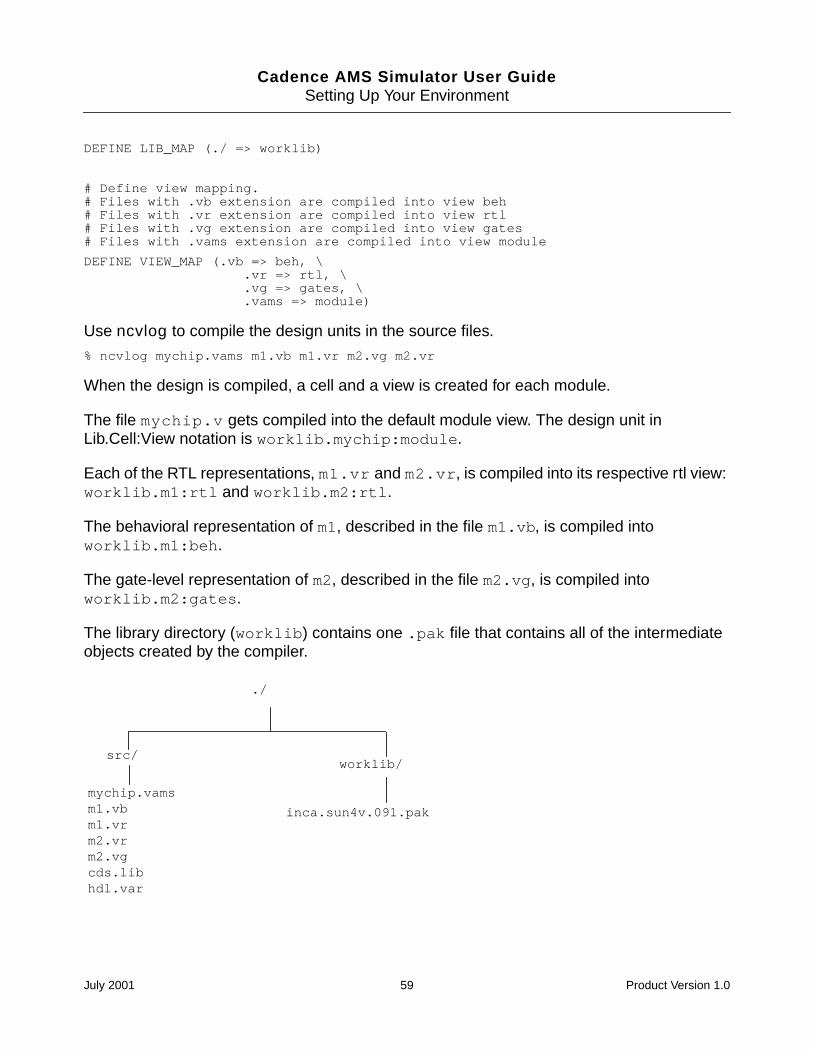
Cadence AMS Simulator User GuideSetting Up Your Environment
DEFINE LIB_MAP (./ => worklib)
# Define view mapping.# Files with .vb extension are compiled into view beh# Files with .vr extension are compiled into view rtl# Files with .vg extension are compiled into view gates# Files with .vams extension are compiled into view module
DEFINE VIEW_MAP (.vb => beh, \.vr => rtl, \.vg => gates, \.vams => module)
Use ncvlog to compile the design units in the source files.
% ncvlog mychip.vams m1.vb m1.vr m2.vg m2.vr
When the design is compiled, a cell and a view is created for each module.
The file mychip.v gets compiled into the default module view. The design unit inLib.Cell:View notation is worklib.mychip:module.
Each of the RTL representations, m1.vr and m2.vr, is compiled into its respective rtl view:worklib.m1:rtl and worklib.m2:rtl.
The behavioral representation of m1, described in the file m1.vb, is compiled intoworklib.m1:beh.
The gate-level representation of m2, described in the file m2.vg, is compiled intoworklib.m2:gates.
The library directory (worklib) contains one .pak file that contains all of the intermediateobjects created by the compiler.
src/
mychip.vamsm1.vbm1.vrm2.vrm2.vgcds.libhdl.var
worklib/
./
inca.sun4v.091.pak
July 2001 59 Product Version 1.0
Cadence AMS Simulator User GuideSetting Up Your Environment
In this example, the top-level module is called mychip. To elaborate the design, specify thisdesign unit on the ncelab command line using the Lib.Cell:View notation, as follows:
% ncelab worklib.mychip:module
Because there is only one view of module mychip in the library, the library and the viewspecification could be omitted, as follows:
% ncelab mychip
The elaborator generates a simulation snapshot for the design. Intermediate objects createdduring the elaboration phase are stored in the .pak file. The snapshot is also a Lib.Cell:View.In this example, the snapshot is called worklib.mychip:module. See Chapter 7,“Elaborating,” for details on how the elaborator names snapshots.
You can now invoke the ncsim simulator by specifying the name of the snapshot on thecommand line, as follows:
% ncsim worklib.mychip:module
Because there is only one snapshot in the library, the library and the view specification couldbe omitted, as follows:
% ncsim mychip
July 2001 60 Product Version 1.0
Cadence AMS Simulator User Guide
4Instantiating Analog Primitives andSubcircuits
This chapter describes how you can instantiate analog primitives and subcircuits in yourdesign. This sections in this chapter are:
Overview on page 62
Using Spectre Built-In and Verilog-AMS Primitives on page 62
Using Subcircuits and Models Written in SPICE or Spectre on page 63
Using Inline Subcircuits on page 64
July 2001 61 Product Version 1.0
Cadence AMS Simulator User GuideInstantiating Analog Primitives and Subcircuits
Overview
The Cadence AMS simulator allows you to instantiate analog masters in your code. With thiscapability, you can use Spectre and SPICE masters to facilitate design development. You canalso instantiate Verilog-AMS analog primitives.
As the following sections describe, using some of the masters requires you to use an analogprimitive table, which is a table listing the primitives that can be instantiated in yourVerilog-AMS code.
Using Spectre Built-In and Verilog-AMS Primitives
The Spectre built-in primitives and the Verilog-AMS primitives in the AMS simulator comprisea single set of primitives. This discussion uses the phrase “Spectre primitives” to refer to thatset.
The Spectre primitives that you can use are listed in the following file:
inst_dir/platform/affirma_ams/etc/files/spec_builtin.apt
The file, with some lines removed for brevity, looks like this.
// Analog primitive file// Copyrights: Cadence Design Systems// Automatically generated by genalgprim
// Generated on: 8:29:35 AM, Tue Oct 17, 2000
primtable
// **** list of built in primitives ****primitive vccs;primitive vbic;primitive tom2;primitive svcvs;primitive svccs;primitive resistor;...endprimtable
For detailed information about the primitives, see the “Components Statement” chapter of theAffirma Spectre Circuit Simulator Reference.
You instantiate a Spectre primitive using the normal Verilog-AMS syntax for instantiatingmodules, except that nodes must be bound to ports by order, and parameters must be set byname. For example, you can instantiate a resistor like this:
resistor #(.r(1K)) R1(pos,neg) ;
July 2001 62 Product Version 1.0
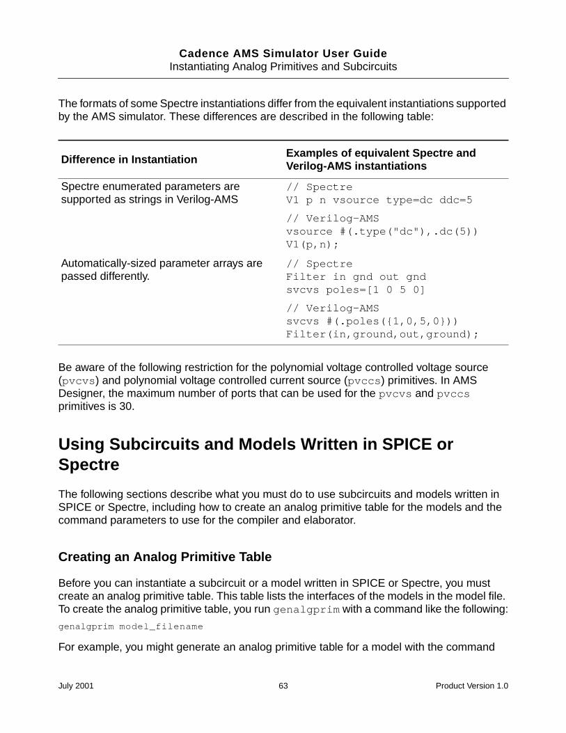
Cadence AMS Simulator User GuideInstantiating Analog Primitives and Subcircuits
The formats of some Spectre instantiations differ from the equivalent instantiations supportedby the AMS simulator. These differences are described in the following table:
Be aware of the following restriction for the polynomial voltage controlled voltage source(pvcvs) and polynomial voltage controlled current source (pvccs) primitives. In AMSDesigner, the maximum number of ports that can be used for the pvcvs and pvccsprimitives is 30.
Using Subcircuits and Models Written in SPICE orSpectre
The following sections describe what you must do to use subcircuits and models written inSPICE or Spectre, including how to create an analog primitive table for the models and thecommand parameters to use for the compiler and elaborator.
Creating an Analog Primitive Table
Before you can instantiate a subcircuit or a model written in SPICE or Spectre, you mustcreate an analog primitive table. This table lists the interfaces of the models in the model file.To create the analog primitive table, you run genalgprim with a command like the following:
genalgprim model_filename
For example, you might generate an analog primitive table for a model with the command
Difference in Instantiation Examples of equivalent Spectre andVerilog-AMS instantiations
Spectre enumerated parameters aresupported as strings in Verilog-AMS
// SpectreV1 p n vsource type=dc ddc=5
// Verilog-AMSvsource #(.type("dc"),.dc(5))V1(p,n);
Automatically-sized parameter arrays arepassed differently.
// SpectreFilter in gnd out gndsvcvs poles=[1 0 5 0]
// Verilog-AMSsvcvs #(.poles(1,0,5,0))Filter(in,ground,out,ground);
July 2001 63 Product Version 1.0
Cadence AMS Simulator User GuideInstantiating Analog Primitives and Subcircuits
genalgprim ~john/models/fab6/models
The analog primitive table is created in the same directory as the model file and must remainin the same directory as the model file. If you move the model file, you must also move theanalog primitive table.
The analog primitive table has the same name as the model but with the extension .apt. Forexample, the analog primitive table for the above example is named models.apt.
After generating the analog primitive table, you do not need to regenerate it unless the modelfile changes.
Passing the Location of the Analog Primitive Table to the Compiler andElaborator
To prepare to simulate a model written in SPICE or Spectre, you must give the compiler andelaborator the location of the analog primitive file. There are two ways to do this.
Define the ALGPRIMPATH variable in the hdl.var file. For more information, see“ALGPRIMPATH Variable” on page 79.
Use the -algprimpath option for ncvlog and ncelab. For more information, see“-ALgprimpath option” on page 76.
Using Inline Subcircuits
The Cadence AMS simulator treats inline subcircuits just like regular subcircuits. However,the inline subcircuits must be listed in the analog primitive table that you use for your design.See the information in “Using Subcircuits and Models Written in SPICE or Spectre” onpage 63 for information on using analog primitive tables.
July 2001 64 Product Version 1.0
Cadence AMS Simulator User Guide
5Importing Verilog-AMS Modules intoVHDL Modules
This chapter explains how to import a Verilog-AMS module into a VHDL design unit, anoperation that requires using shells.
The sections in this chapter are
Overview on page 66
Generating a Shell with ncshell on page 66
July 2001 65 Product Version 1.0
Cadence AMS Simulator User GuideImporting Verilog-AMS Modules into VHDL Modules
Overview
Verilog-AMS is a mixed-signal language but VHDL is only digital. As a consequence, aVerilog-AMS module that you want to import into VHDL must first be wrapped so that to thesimulator, the wrapped module appears to be a VHDL module. There are two shells involvedin the wrapping. The first shell is a digital Verilog shell that, in turn, is wrapped in a VHDL shell.To generate these shells, you use the ncshell utility.
This technique for importing Verilog-AMS modules into VHDL requires the use of theCadence library.cell:view configurations, sometimes referred to as 5.X configurations, forelaboration.
Generating a Shell with ncshell
For detailed information about using the ncshell utility, see the “Mixed Verilog/VHDLSimulation” chapter, in the Affirma NC VHDL Simulator Help. This section describes onlythe steps and options required to import Verilog-AMS modules into VHDL modules.
In the simplest case, you invoke ncshell with a command like the following.
ncshell -import verilog -ams -into vhdl [other_options] lib.cell:view
-import verilog Specifies that model being imported is Verilog, Verilog-A, orVerilog-AMS.
-ams Specifies that the imported model is to be interpreted as aVerilog-AMS model. This option is required if the module you areimporting is a Verilog-AMS (or Verilog-A) module.
-into vhdl Specifies that the model is to be imported into a VHDL module.
other_options One or more of the following options: -package name or -viewname, which are described below, or the options described in the“ncshell Command Options” section of the “Mixed Verilog/VHDLSimulation” chapter, in the Affirma NC VHDL Simulator Help.
In addition, if the module to be imported uses parameters, youmust use the -generic option to ensure that the parametersare available in the shell.
library.cell:view The compiled design unit that you want to import. If the designunit is not compiled, you can add the -analyze option to thencshell command.
July 2001 66 Product Version 1.0
Cadence AMS Simulator User GuideImporting Verilog-AMS Modules into VHDL Modules
The -package name option allows you to specify the package name for the VHDL packagegenerated by ncshell. The -view name option allows you to specify the cellview name tobe used for the digital Verilog shell and for the architecture name of the VHDL shell.
For example, assuming that the comparator is a compiled Verilog-AMS module that usesparameters, you can create a shell for it by using the following command.
ncshell -import verilog -ams -into vhdl -generic comparator
If the Verilog-AMS module, located in the file comparator.vams, is not compiled, you mightenter a command like the following.
ncshell -import verilog -ams -into vhdl -generic -analyze comparator.vamscomparator
Restrictions
The ncshell tool does not support the wreal port type.
Steps to Follow
To import Verilog-AMS into VHDL:
1. Use the ncvlog compiler to compile the Verilog-AMS source code for the module that youwant to import.
2. Use the ncshell utility to generate model import shells for the module you want toimport.
3. In the source VHDL file, specify the architecture name to be used for entity. If youspecified the -view option for the ncshell utility in the previous step, use that name forthe architecture. If you did not specify the -view option, use verilog for thearchitecture name.
4. Add a clause in the source VHDL file to specify the package. If you specified the -package option for the ncshell utility in Step 2, use a clause like
use library.packagename.all ;
If you did not specify the -package option, use a clause like
use library.HDLModels.all;
5. Compile all VHDL source code using ncvhdl.
6. Elaborate the design using the ncelab elaborator.
July 2001 67 Product Version 1.0
Cadence AMS Simulator User GuideImporting Verilog-AMS Modules into VHDL Modules
Example
For example, suppose that you want to import the following Verilog-AMS module, which is inthe file comparator_analog.v.
‘include "discipline.h"‘include "constants.h"
module comparator(cout, inp, inm);output cout;input inp, inm;electrical cout, inp, inm;parameter real td = 1n, tr = 1n, tf = 1n;parameter integer i = 4.5, j = 5.49;
endmodule
1. Compile the Verilog-AMS source code.
ncvlog -ams -use5x comparator_analog.v
If your working library is amsLib, this command compiles the module comparator intoamslib.comparator:module. The -use5x option is used because 5.X configurationsare used later to elaborate the design.
2. Generate model import shells using ncshell. The argument to the ncshell commandis the lib.cell:view specification for the compiled module.
ncshell -import verilog -ams -into vhdl -generic amslib.comparator:module
This command generates two shells. The digital Verilog shell, generated in the filecomparator.vds, looks like this:
module comparator(cout, inp, inm);output cout ;input inp ;input inm ;
parameter td = 1.000000e09, tr = 1.000000e-09, tf = 1.000000e-09,i = 5, j = 5 ;
comparator #(.td(td), .tr(tr), .tf(tf))(* integer view_binding="module"; *) comparator1(.cout(cout), .inp(inp), .inm(inm));
endmodule
This module has an instance comparator1 of the same cellname comparator. It alsohas a view binding attribute module, which binds the instance to theamslib.comparator:module view. The source that is compiled into theamslib.comparator:module view is a Verilog-AMS description. This switches theelaborator into using the Verilog-AMS language.
The VHDL shell, generated in a file called comparator.vhd, looks like this:
library ieee;use ieee.std_logic_1164.all;
July 2001 68 Product Version 1.0
Cadence AMS Simulator User GuideImporting Verilog-AMS Modules into VHDL Modules
entity comparator isgeneric (
td: real := 1.000000e-09;tr: real := 1.000000e-09;tf: real := 1.000000e-09,i: integer := 5,j: integer := 5
);
port (cout: out std_logic;inp: in std_logic;inm: in std_logic
);end comparator;
architecture verilog of comparator isattribute foreign of verilog:architecture is "VERILOG(event)amslib.comparator:digital_shell";
beginend;
Notice that the name of the architecture in the shell defaults to verilog.
The architecture verilog has a foreign attributeamslib.comparator:digital_shell, which tells the elaborator that thearchitecture is actually a shell for the Verilog module compiled into the viewamslib.comparator:digital_shell. This attribute causes the elaborator to switchfrom the VHDL language into digital Verilog.
The ncshell utility also generates the following VHDL component declaration in the filecomparator_comp.vhd:
library ieee;use ieee.std_logic_1164.all;
package HDLModels is
component comparatorgeneric (
td: real := 1.000000e-09;tr: real := 1.000000e-09;tf: real := 1.000000e-09, i: integer := 5, j: integer := 5
);
port (cout: out std_logic;inp: in std_logic;inm: in std_logic
);end component;
end HDLModels;
Note: In Verilog-AMS, identifiers are case-sensitive. By default, mixed-case anduppercase identifiers in Verilog-AMS are escaped in VHDL shells. For example, if the
July 2001 69 Product Version 1.0
Cadence AMS Simulator User GuideImporting Verilog-AMS Modules into VHDL Modules
Verilog-AMS module is Vlog, this identifier appears in the VHDL shell as \Vlog\. Usethe -noescape option if you want the Verilog-AMS module name to be matched exactlyin the shell. Do not set the CDS_ALT_NMP environment variable, which is not supported.
3. In the source VHDL file, specify that architecture verilog is to be used for entitycomparator (because this example uses the default value). Add the use clause (usingthe default version). With these changes, the source VHDL file for this example looks like:
-- top.vhdlibrary ieee;use ieee.std_logic_1164.all;use work.HDLModels.all;entity top isend top;
architecture testbench of top issignal in1, in2, output : std_logic;for all: comparator use entity work.comparator(verilog);
begin
test: process beginin1 <= ’0’;in2 <= ’0’;wait;
end process;
comparator12: comparator port map(output, in1, in2);
end;
The for all statement binds the comparator instance to the design unit inamslib.comparator:verilog, which is a compiled version of the architectureverilog.
4. Compile the top-level VHDL file (top.vhd) and the VHDL package generated earlier byncshell.
ncvhdl -v93 comparator_comp.vhd top.vhd -use5x
5. Elaborate the design with ncelab. Assuming that the corresponding 5.X configuration isamslib.top:config and that the connectrules module is compiled intoamslib.AMSconnect:module, you can elaborate the design with a command like:
ncelab amslib.top:config AMSconnect -discipline logic
In this example, using the -discipline logic option sets the discipline of the shellports to logic.
July 2001 70 Product Version 1.0
Cadence AMS Simulator User Guide
6Compiling
This chapter contains the following sections:
Overview on page 72
ncvlog Command Syntax on page 73
hdl.var Variables on page 78
Conditionally Compiling Source Code on page 79
Controlling the Compilation of Design Units into Library.Cell:View on page 80
July 2001 71 Product Version 1.0
Cadence AMS Simulator User GuideCompiling
Overview
After writing or editing your source files, the next step is to analyze and compile them. Theprogram that you use to analyze and compile Verilog-AMS source is called ncvlog.
ncvlog performs syntactic and static semantic checking on the HDL design units (modules,macromodules, or UDPs). If no errors are found, compilation produces an internalrepresentation for each HDL design unit in the source files. These intermediate objects arestored in a library database file in the library directory.
You run ncvlog with options and one or more source file names. The arguments can be usedin any order provided that option parameters immediately follow the option they modify. Youcan also run ncvlog with the -unit or -specificunit option and a design unit name.
To run ncvlog on Verilog-AMS modules, be sure to use the -ams option.
For example
% ncvlog -ams foo.v foo2.vms // foo.v and foo2.vms are source files
% ncvlog -ams -unit worklib.mymod // mymod is an HDL design unit
ncvlog treats each command-line argument that is not an option or a parameter to an optionas a filename. For each filename, ncvlog first tries to open the file as specified. If this fails,each file extension specified with the VERILOG_SUFFIX variable is appended to the name,and ncvlog tries to open the file. The default file extension is .v. If no match is found, ncvlogtries the list of possible suffixes in the hdl.var variable VIEW_MAP. If all suffixes areexhausted, ncvlog issues an error.
For details on the VERILOG_SUFFIX and VIEW_MAP variables, see the “hdl.var Variables”section of the “Compiling Verilog Source Files With ncvlog” chapter, in the Affirma NCVerilog Simulator Help.
ncvlog compiles each design unit into a Library.Cell:View. See “The Library.Cell:ViewApproach” on page 36 for information on the Cadence AMS simulator library system.
ncvlog always sets the cell name to the name of the design unit, but you can specify thelibrary where the compiler stores compiled objects and the view names that are assigned tothem. See “Controlling the Compilation of Design Units into Library.Cell:View” on page 80 formore information.
In addition to the intermediate objects for each HDL design unit, ncvlog can generate threeother files: master.tag, verilog.v, and pc.db. These files are required
If you want to browse libraries using the graphical user interface.
If you want to use configurations.
July 2001 72 Product Version 1.0
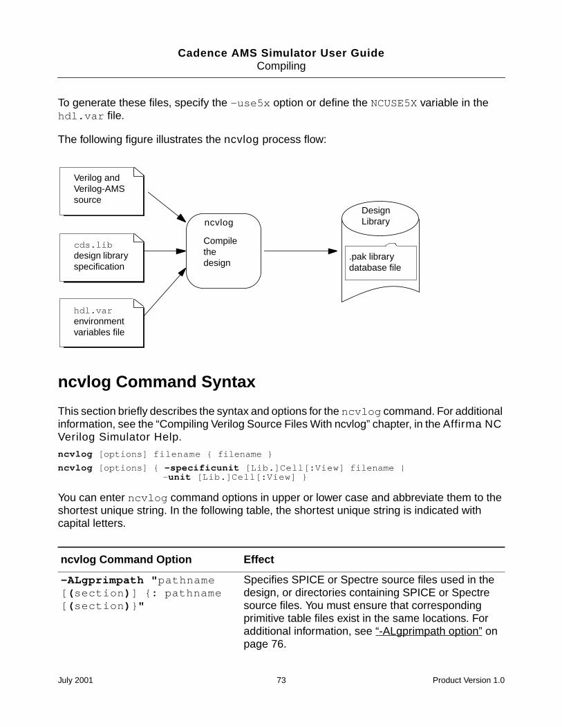
Cadence AMS Simulator User GuideCompiling
To generate these files, specify the -use5x option or define the NCUSE5X variable in thehdl.var file.
The following figure illustrates the ncvlog process flow:
ncvlog Command Syntax
This section briefly describes the syntax and options for the ncvlog command. For additionalinformation, see the “Compiling Verilog Source Files With ncvlog” chapter, in the Affirma NCVerilog Simulator Help.
ncvlog [options] filename filename
ncvlog [options] -specificunit [Lib.]Cell[:View] filename |-unit [Lib.]Cell[:View]
You can enter ncvlog command options in upper or lower case and abbreviate them to theshortest unique string. In the following table, the shortest unique string is indicated withcapital letters.
ncvlog Command Option Effect
-ALgprimpath "pathname[(section)] : pathname[(section)"
Specifies SPICE or Spectre source files used in thedesign, or directories containing SPICE or Spectresource files. You must ensure that correspondingprimitive table files exist in the same locations. Foradditional information, see “-ALgprimpath option” onpage 76.
Verilog andVerilog-AMSsource
cds.libdesign libraryspecification
hdl.varenvironmentvariables file
ncvlog
Compilethedesign
.pak librarydatabase file
DesignLibrary
July 2001 73 Product Version 1.0
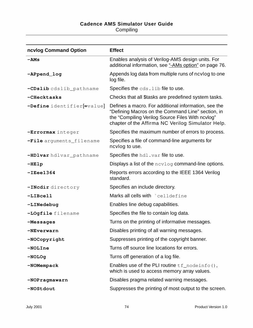
Cadence AMS Simulator User GuideCompiling
-AMs Enables analysis of Verilog-AMS design units. Foradditional information, see “-AMs option” on page 76.
-APpend_log Appends log data from multiple runs of ncvlog to onelog file.
-CDslib cdslib_pathname Specifies the cds.lib file to use.
-CHecktasks Checks that all $tasks are predefined system tasks.
-Define identifier[=value] Defines a macro. For additional information, see the“Defining Macros on the Command Line” section, inthe “Compiling Verilog Source Files With ncvlog”chapter of the Affirma NC Verilog Simulator Help.
-Errormax integer Specifies the maximum number of errors to process.
-File arguments_filename Specifies a file of command-line arguments forncvlog to use.
-HDlvar hdlvar_pathname Specifies the hdl.var file to use.
-HElp Displays a list of the ncvlog command-line options.
-IEee1364 Reports errors according to the IEEE 1364 Verilogstandard.
-INcdir directory Specifies an include directory.
-LIBcell Marks all cells with `celldefine
-LINedebug Enables line debug capabilities.
-LOgfile filename Specifies the file to contain log data.
-Messages Turns on the printing of informative messages.
-NEverwarn Disables printing of all warning messages.
-NOCopyright Suppresses printing of the copyright banner.
-NOLIne Turns off source line locations for errors.
-NOLOg Turns off generation of a log file.
-NOMempack Enables use of the PLI routine tf_nodeinfo(),which is used to access memory array values.
-NOPragmawarn Disables pragma related warning messages.
-NOStdout Suppresses the printing of most output to the screen.
ncvlog Command Option Effect
July 2001 74 Product Version 1.0
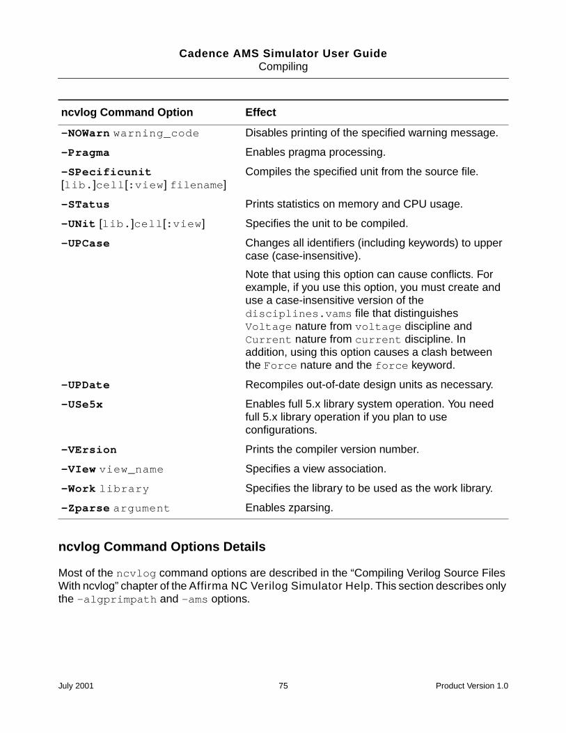
Cadence AMS Simulator User GuideCompiling
ncvlog Command Options Details
Most of the ncvlog command options are described in the “Compiling Verilog Source FilesWith ncvlog” chapter of the Affirma NC Verilog Simulator Help. This section describes onlythe -algprimpath and -ams options.
-NOWarn warning_code Disables printing of the specified warning message.
-Pragma Enables pragma processing.
-SPecificunit[lib.]cell[:view] filename]
Compiles the specified unit from the source file.
-STatus Prints statistics on memory and CPU usage.
-UNit [lib.]cell[:view] Specifies the unit to be compiled.
-UPCase Changes all identifiers (including keywords) to uppercase (case-insensitive).
Note that using this option can cause conflicts. Forexample, if you use this option, you must create anduse a case-insensitive version of thedisciplines.vams file that distinguishesVoltage nature from voltage discipline andCurrent nature from current discipline. Inaddition, using this option causes a clash betweenthe Force nature and the force keyword.
-UPDate Recompiles out-of-date design units as necessary.
-USe5x Enables full 5.x library system operation. You needfull 5.x library operation if you plan to useconfigurations.
-VErsion Prints the compiler version number.
-VIew view_name Specifies a view association.
-Work library Specifies the library to be used as the work library.
-Zparse argument Enables zparsing.
ncvlog Command Option Effect
July 2001 75 Product Version 1.0
Cadence AMS Simulator User GuideCompiling
-ALgprimpath option
Specifies the SPICE or Spectre source files for the models used in your design, or directoriescontaining the SPICE or Spectre source files for models. You must ensure that correspondingprimitive table files (with the extension .apt) exist in the same locations. ncvlog and ncelabuse the primitive table files to determine which primitives to load.
You can also achieve the same result by defining the ALGPRIMPATH variable in the hdl.varfile. For more information, see “The hdl.var File” on page 45.
For example, assume that the file simple_cap.m contains the following Verilog-AMSdefinition. This file instantiates an analog model, my_mod_cap.
// cap model definition
simulator lang=spectreparameters base=8
model my_mod_cap capacitor c=2u tc1=1.2e-8tnom=(17 + base) w=4u l=4u cjsw=2.4e-10
The primitive table file, simple_cap.m.apt, which must be in the same directory assimple_cap.m, contains the following corresponding definition.
// primitive table file
primtableprimitive my_mod_cap;
endprimtable
You can use these definitions in a command like this one.
ncvlog -ams -algprimpath simple_cap.m
If you are using sections, quotation marks are required as illustrated in the next example.
ncvlog -ams -algprimpath "mymos(typ)"
You use the genalgprim utility to generate primitive table files. For more information, see“Creating an Analog Primitive Table” on page 63.
-AMs option
Enables analysis of Verilog-AMS design units. Use this option to tell ncvlog that some or allof the HDL design units are written in the Verilog-AMS language. If you do not use this option,ncvlog analyzes for the Verilog language, which is likely to result in many errors when thelanguage is actually Verilog-AMS.
For example, to compile the files ms10.v and ms12.v, which both contain modules writtenwith Verilog-AMS, you can use a command like
July 2001 76 Product Version 1.0
Cadence AMS Simulator User GuideCompiling
ncvlog -ams ms10.v ms12.v
Be careful to use the -AMs option only when appropriate. For example, using the option withlegacy digital Verilog modules can cause errors if Verilog-AMS keywords are used asidentifiers in the Verilog modules.
Example ncvlog Command Lines
The following command includes the -messages option, which prints compiler messages.
% ncvlog -messages 2bit_adder_test.v
ncvlog: v1.0.(p1): (c) Copyright 1995 - 2000 Cadence Design Systems, Inc.file: 2bit_adder_test.v module worklib.top errors: 0, warnings: 0%
The following example uses the -work option to define the current working library asaludesign. This overrides the definition of the WORK variable in the hdl.var file.
% ncvlog -work aludesign 2bit_adder_test.v
The following example uses the -file option to include a file called ncvlog.vc, whichincludes a set of command-line options, such as -messages, -nocopyright, -errormax,and -incdir.
% ncvlog -file ncvlog.vc 2bit_adder_test.v
In the following example, the -ieee1364 option checks for compatibility with the IEEEspecification. Error messages reference the IEEE Language Reference Manual.
% ncvlog -ieee1364 2bit_adder_test.v
The following example includes the -incdir option to specify a directory to search forinclude files.
% ncvlog -incdir ~larrybird/bigdesign 2bit_adder_test.v
In the following example, -errormax 10 tells the compiler to stop compiling after 10 errors.The -noline option suppresses the reporting of source lines when errors are encountered.Using this option can improve performance when compiling very large source files thatcontain errors.
% ncvlog -errormax 10 -noline 2bit_adder.v
The following example includes the -logfile option to send output to a log file calledadder.log instead of to the default log file ncvlog.log.
% ncvlog -messages -logfile adder.log 2bit_adder.v
July 2001 77 Product Version 1.0
Cadence AMS Simulator User GuideCompiling
The following example includes the -linedebug option, which disables the optimizationsthat prevent line debug capabilities.
% ncvlog -linedebug 2bit_adder.v
The following example illustrates how to use the -algprimpath and -ams options tocompile Verilog-AMS modules that use primitives. The directory that holds simp_res.mmust have another file named simp_res.m.apt, which is a primitive table.
% ncvlog -ams -algprimpath "simp_res.m" 2bit_adder.v
The following example illustrates using the -use5x option. You need to use this option if youplan to use a configuration when you elaborate.
% ncvlog -ams -use5x top
hdl.var Variables
This section lists the hdl.var variables used by ncvlog. For additional information, see the“hdl.var Variables” section of the “Compiling Verilog Source Files With ncvlog” chapter, in theAffirma NC Verilog Simulator Help.
hdl.var Variables Usedby ncvlog Description
ALGPRIMPATH Specifies the SPICE or Spectre source files for the modelsused in your design, or directories containing the SPICE orSpectre source files for models. For additional information, see“ALGPRIMPATH Variable” on page 79.
LIB_MAP Maps files and directories to the names of libraries where youwant them to be compiled.
NCUSE5X Turns on generation of the master.tag, verilog.v, andpc.db files, which are required if you want to use the librarybrowser in the graphical user interface. These files are alsorequired if you plan to use configurations.
NCVLOGOPTS Adds additional argument to the ncvlog command.
SRC_ROOT Defines an ordered list of paths to search for source files whenyou are updating a design.
VERILOG_SUFFIX Specifies valid file extensions for Verilog source files.
VIEW Specifies the view name to use.
VIEW_MAP Maps file extensions to view names.
July 2001 78 Product Version 1.0
Cadence AMS Simulator User GuideCompiling
ALGPRIMPATH Variable
This variable specifies the SPICE or Spectre source files for the models used in your design,or directories containing the SPICE or Spectre source files for models. You must ensure thatcorresponding primitive table files (with the extension .apt) exist in the same locations.ncvlog uses the primitive table files to determine which primitives to load.
For example, assume that the model file, simple_cap.m, contains the following definition.
// cap model definition
simulator lang=spectreparameters base=8
model my_mod_cap capacitor c=2u tc1=1.2e-8tnom=(17 + base) w=4u l=4u cjsw=2.4e-10
The primitive table file, simple_cap.m.apt, which must be in the same directory assimple_cap.m, contains the following corresponding definition.
// primitive table file
primtableprimitive my_mod_cap;
endprimtable
You can use a statement like the following to define an hdl.var variable that uses thesedefinitions.
DEFINE ALGPRIMPATH simple_cap.m
If you are using sections, use a statement like the following. This statement indicates that thetyp sections are to be used for each of the two models. Notice how the models are separatedby a colon, without any white space.
DEFINE ALGPRIMPATH mymos(typ):yourmos(typ)
Conditionally Compiling Source Code
Use the conditional compilation compiler directives (`ifdef, `else, and `endif) toinclude lines of an HDL source description conditionally during compilation. The `ifdefcompiler directive checks whether a variable name is defined either in the source code or on
WORK Specifies the work library.
hdl.var Variables Usedby ncvlog Description
July 2001 79 Product Version 1.0
Cadence AMS Simulator User GuideCompiling
the command line. If the variable name is defined, the compiler includes the lines in thesource description.
For additional information on these directives and on other directives that you can use forconditional compilation, see the “Controlling the Compiler” chapter of the CadenceVerilog-AMS Language Reference.
Controlling the Compilation of Design Units intoLibrary.Cell:View
When you run the ncvlog compiler, your HDL design units (modules, macromodules, andUDPs) are compiled into a Library.Cell:View. The cell name is always set to the name of thedesign unit, but you can control where the compiler stores compiled objects and the viewnames that are assigned to them.
To specify the library and view, you can use variables defined in the hdl.var file,command-line options, or compiler directives. The order of precedence is as follows. Thecross-references are to sections in the “Compiling Verilog Source Files With ncvlog” chapter,in the Affirma NC Verilog Simulator Help.
1. By default, the library to compile into is the work library. See “The Default” section.
2. The definitions of the LIB_MAP and VIEW_MAP variables in the hdl.var file. See “TheLIB_MAP and VIEW_MAP Variables” section.
3. The definitions of the WORK and VIEW variables in the hdl.var file. See “The WORKand VIEW Variables” section.
4. The -work or -view command-line options. See “The -work and -view Options” section.
5. The -specificunit command-line option with a library and/or view specification. See“The -specificunit Option” section.
6. The `worklib and `view compiler directives. See “The `worklib and `view CompilerDirectives” section.
See the “Mapping of Modules Defined Within `include Files” section for information on thelibrary and view mapping of modules defined within `include files.
July 2001 80 Product Version 1.0
Cadence AMS Simulator User Guide
7Elaborating
This chapter contains the following sections:
Overview on page 82
ncelab Command Syntax and Options on page 83
Example ncelab Command Lines on page 91
hdl.var Variables on page 92
How Modules and UDPs Are Resolved During Elaboration on page 93
Enabling Read, Write, or Connectivity Access to Digital Simulation Objects on page 94
Selecting a Delay Mode on page 95
Setting Pulse Controls on page 95
July 2001 81 Product Version 1.0
Cadence AMS Simulator User GuideElaborating
Overview
Before you can simulate your model, the design hierarchy defining the model must beelaborated. The tool you use for elaborating the design is called ncelab.
ncelab is a language-independent elaborator. It handles imported netlists such as Spectreand SPICE netlists, constructs a design hierarchy based on the instantiation andconfiguration information in the design, establishes signal connectivity, and computes initialvalues for all objects in the design. The elaborated design hierarchy is stored in simulationsnapshots, which are the representation of your design that the simulator uses to run thesimulation. The snapshots are stored in the library database file along with the otherintermediate objects generated by the compiler and elaborator.
You run ncelab with command-line options and the Library.Cell:View name or names of thetop-level HDL design units.
The top-level units specified on the command line can be:
Exactly one VHDL top-level unit.
One or more Verilog or Verilog-AMS top-level units.
Exactly one VHDL unit and one or more Verilog or Verilog-AMS units.
One configuration.
In addition, especially if you are using the Cadence AMS environment, you might specify:
The cds_globals module.
The connectrules module.
Design units specified on the command line cannot be instantiated beneath themselves in thedesign because this practice results in recursive instantiations.
July 2001 82 Product Version 1.0
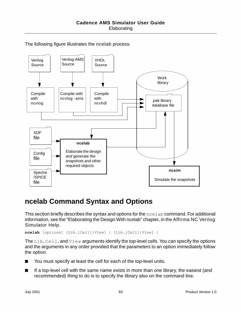
Cadence AMS Simulator User GuideElaborating
The following figure illustrates the ncelab process.
ncelab Command Syntax and Options
This section briefly describes the syntax and options for the ncelab command. For additionalinformation, see the “Elaborating the Design With ncelab” chapter, in the Affirma NC VerilogSimulator Help.
ncelab [options] [Lib.]Cell[:View] [Lib.]Cell[:View]
The Lib, Cell, and View arguments identify the top-level cells. You can specify the optionsand the arguments in any order provided that the parameters to an option immediately followthe option.
You must specify at least the cell for each of the top-level units.
If a top-level cell with the same name exists in more than one library, the easiest (andrecommended) thing to do is to specify the library also on the command line.
SDFfile
Compilewithncvlog
Simulate the snapshots
Worklibrary
VerilogSource
Compilewithncvhdl
VHDLSource
.pak librarydatabase file
Elaborate the designand generate thesnapshots and otherrequired objects
ncelab
ncsim
Compile withncvlog -ams
Verilog-AMSSource
Configfile
Spectre/SPICEfile
July 2001 83 Product Version 1.0
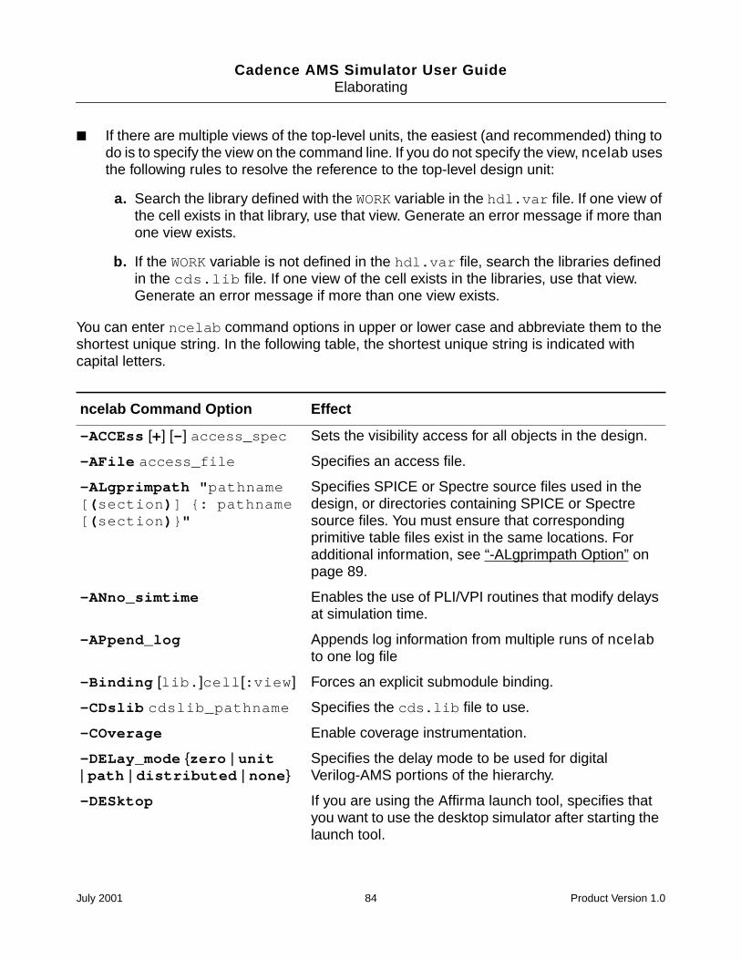
Cadence AMS Simulator User GuideElaborating
If there are multiple views of the top-level units, the easiest (and recommended) thing todo is to specify the view on the command line. If you do not specify the view, ncelab usesthe following rules to resolve the reference to the top-level design unit:
a. Search the library defined with the WORK variable in the hdl.var file. If one view ofthe cell exists in that library, use that view. Generate an error message if more thanone view exists.
b. If the WORK variable is not defined in the hdl.var file, search the libraries definedin the cds.lib file. If one view of the cell exists in the libraries, use that view.Generate an error message if more than one view exists.
You can enter ncelab command options in upper or lower case and abbreviate them to theshortest unique string. In the following table, the shortest unique string is indicated withcapital letters.
ncelab Command Option Effect
-ACCEss [+] [-] access_spec Sets the visibility access for all objects in the design.
-AFile access_file Specifies an access file.
-ALgprimpath "pathname[(section)] : pathname[(section)"
Specifies SPICE or Spectre source files used in thedesign, or directories containing SPICE or Spectresource files. You must ensure that correspondingprimitive table files exist in the same locations. Foradditional information, see “-ALgprimpath Option” onpage 89.
-ANno_simtime Enables the use of PLI/VPI routines that modify delaysat simulation time.
-APpend_log Appends log information from multiple runs of ncelabto one log file
-Binding [lib.]cell[:view] Forces an explicit submodule binding.
-CDslib cdslib_pathname Specifies the cds.lib file to use.
-COverage Enable coverage instrumentation.
-DELay_mode zero | unit| path | distributed | none
Specifies the delay mode to be used for digitalVerilog-AMS portions of the hierarchy.
-DESktop If you are using the Affirma launch tool, specifies thatyou want to use the desktop simulator after starting thelaunch tool.
July 2001 84 Product Version 1.0
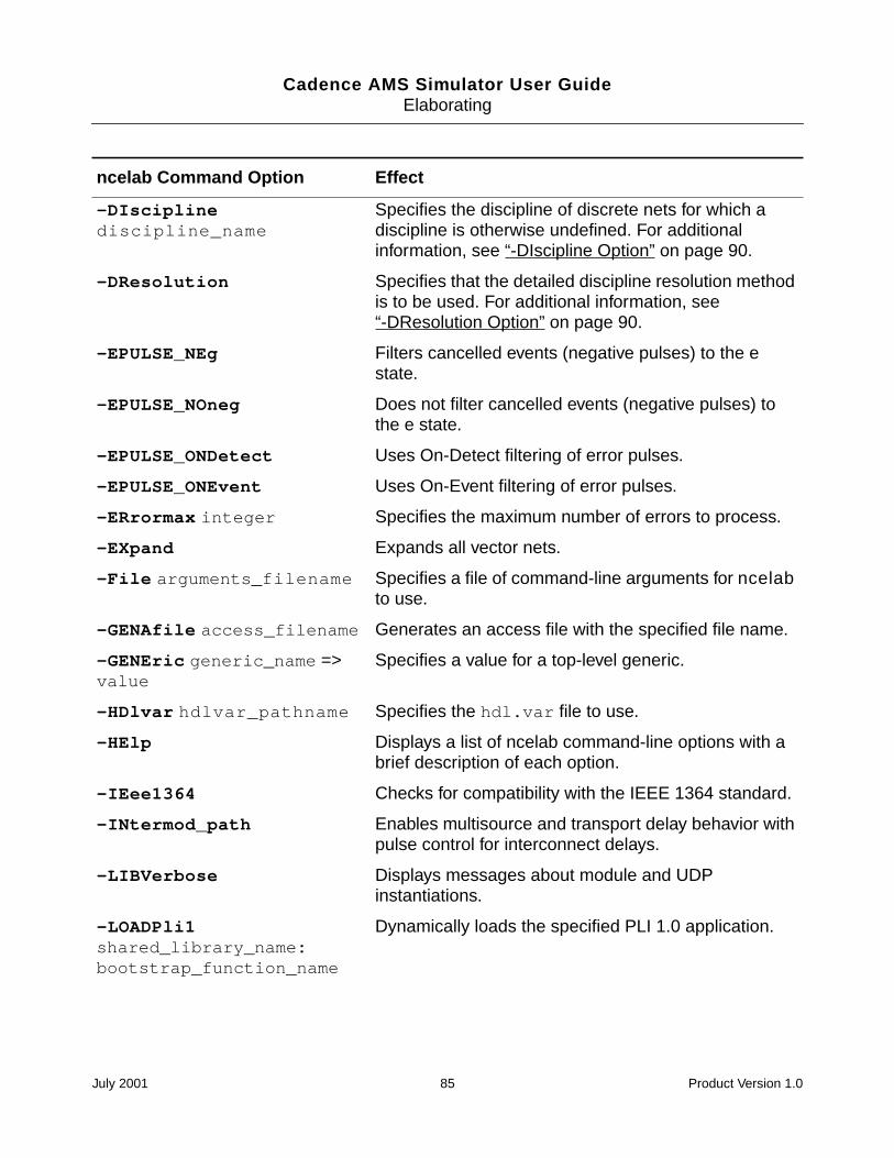
Cadence AMS Simulator User GuideElaborating
-DIsciplinediscipline_name
Specifies the discipline of discrete nets for which adiscipline is otherwise undefined. For additionalinformation, see “-DIscipline Option” on page 90.
-DResolution Specifies that the detailed discipline resolution methodis to be used. For additional information, see“-DResolution Option” on page 90.
-EPULSE_NEg Filters cancelled events (negative pulses) to the estate.
-EPULSE_NOneg Does not filter cancelled events (negative pulses) tothe e state.
-EPULSE_ONDetect Uses On-Detect filtering of error pulses.
-EPULSE_ONEvent Uses On-Event filtering of error pulses.
-ERrormax integer Specifies the maximum number of errors to process.
-EXpand Expands all vector nets.
-File arguments_filename Specifies a file of command-line arguments for ncelabto use.
-GENAfile access_filename Generates an access file with the specified file name.
-GENEric generic_name =>value
Specifies a value for a top-level generic.
-HDlvar hdlvar_pathname Specifies the hdl.var file to use.
-HElp Displays a list of ncelab command-line options with abrief description of each option.
-IEee1364 Checks for compatibility with the IEEE 1364 standard.
-INtermod_path Enables multisource and transport delay behavior withpulse control for interconnect delays.
-LIBVerbose Displays messages about module and UDPinstantiations.
-LOADPli1shared_library_name:bootstrap_function_name
Dynamically loads the specified PLI 1.0 application.
ncelab Command Option Effect
July 2001 85 Product Version 1.0
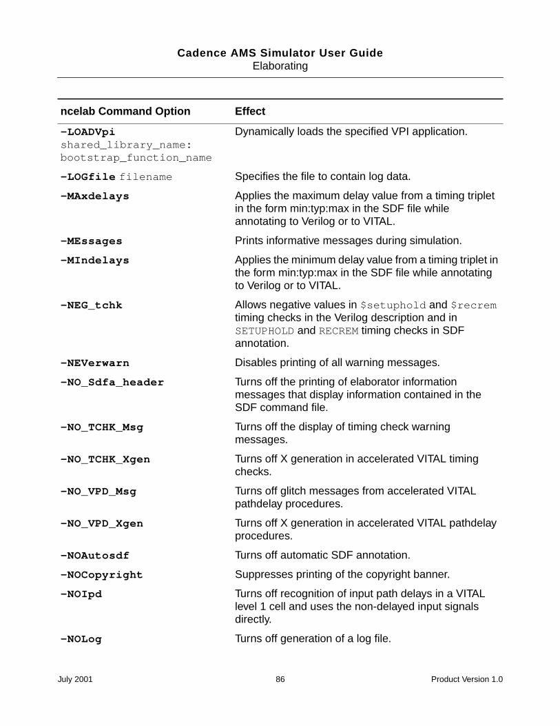
Cadence AMS Simulator User GuideElaborating
-LOADVpishared_library_name:bootstrap_function_name
Dynamically loads the specified VPI application.
-LOGfile filename Specifies the file to contain log data.
-MAxdelays Applies the maximum delay value from a timing tripletin the form min:typ:max in the SDF file whileannotating to Verilog or to VITAL.
-MEssages Prints informative messages during simulation.
-MIndelays Applies the minimum delay value from a timing triplet inthe form min:typ:max in the SDF file while annotatingto Verilog or to VITAL.
-NEG_tchk Allows negative values in $setuphold and $recremtiming checks in the Verilog description and inSETUPHOLD and RECREM timing checks in SDFannotation.
-NEVerwarn Disables printing of all warning messages.
-NO_Sdfa_header Turns off the printing of elaborator informationmessages that display information contained in theSDF command file.
-NO_TCHK_Msg Turns off the display of timing check warningmessages.
-NO_TCHK_Xgen Turns off X generation in accelerated VITAL timingchecks.
-NO_VPD_Msg Turns off glitch messages from accelerated VITALpathdelay procedures.
-NO_VPD_Xgen Turns off X generation in accelerated VITAL pathdelayprocedures.
-NOAutosdf Turns off automatic SDF annotation.
-NOCopyright Suppresses printing of the copyright banner.
-NOIpd Turns off recognition of input path delays in a VITALlevel 1 cell and uses the non-delayed input signalsdirectly.
-NOLog Turns off generation of a log file.
ncelab Command Option Effect
July 2001 86 Product Version 1.0
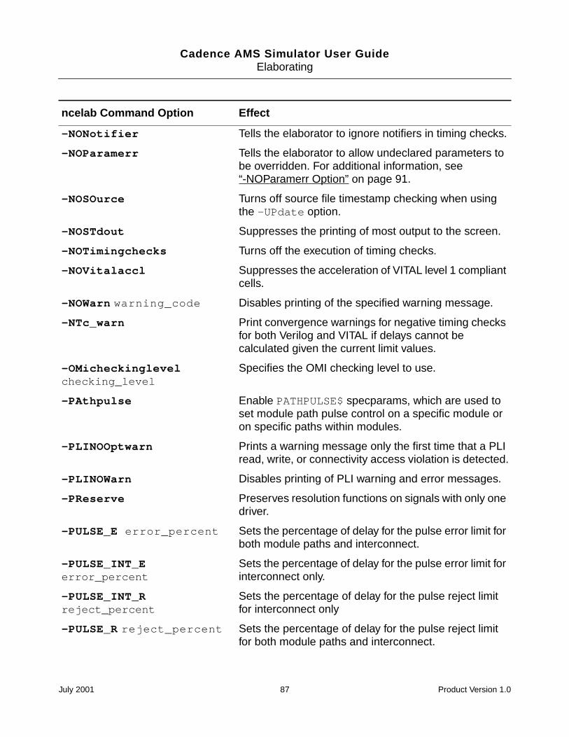
Cadence AMS Simulator User GuideElaborating
-NONotifier Tells the elaborator to ignore notifiers in timing checks.
-NOParamerr Tells the elaborator to allow undeclared parameters tobe overridden. For additional information, see“-NOParamerr Option” on page 91.
-NOSOurce Turns off source file timestamp checking when usingthe -UPdate option.
-NOSTdout Suppresses the printing of most output to the screen.
-NOTimingchecks Turns off the execution of timing checks.
-NOVitalaccl Suppresses the acceleration of VITAL level 1 compliantcells.
-NOWarn warning_code Disables printing of the specified warning message.
-NTc_warn Print convergence warnings for negative timing checksfor both Verilog and VITAL if delays cannot becalculated given the current limit values.
-OMicheckinglevelchecking_level
Specifies the OMI checking level to use.
-PAthpulse Enable PATHPULSE$ specparams, which are used toset module path pulse control on a specific module oron specific paths within modules.
-PLINOOptwarn Prints a warning message only the first time that a PLIread, write, or connectivity access violation is detected.
-PLINOWarn Disables printing of PLI warning and error messages.
-PReserve Preserves resolution functions on signals with only onedriver.
-PULSE_E error_percent Sets the percentage of delay for the pulse error limit forboth module paths and interconnect.
-PULSE_INT_Eerror_percent
Sets the percentage of delay for the pulse error limit forinterconnect only.
-PULSE_INT_Rreject_percent
Sets the percentage of delay for the pulse reject limitfor interconnect only
-PULSE_R reject_percent Sets the percentage of delay for the pulse reject limitfor both module paths and interconnect.
ncelab Command Option Effect
July 2001 87 Product Version 1.0
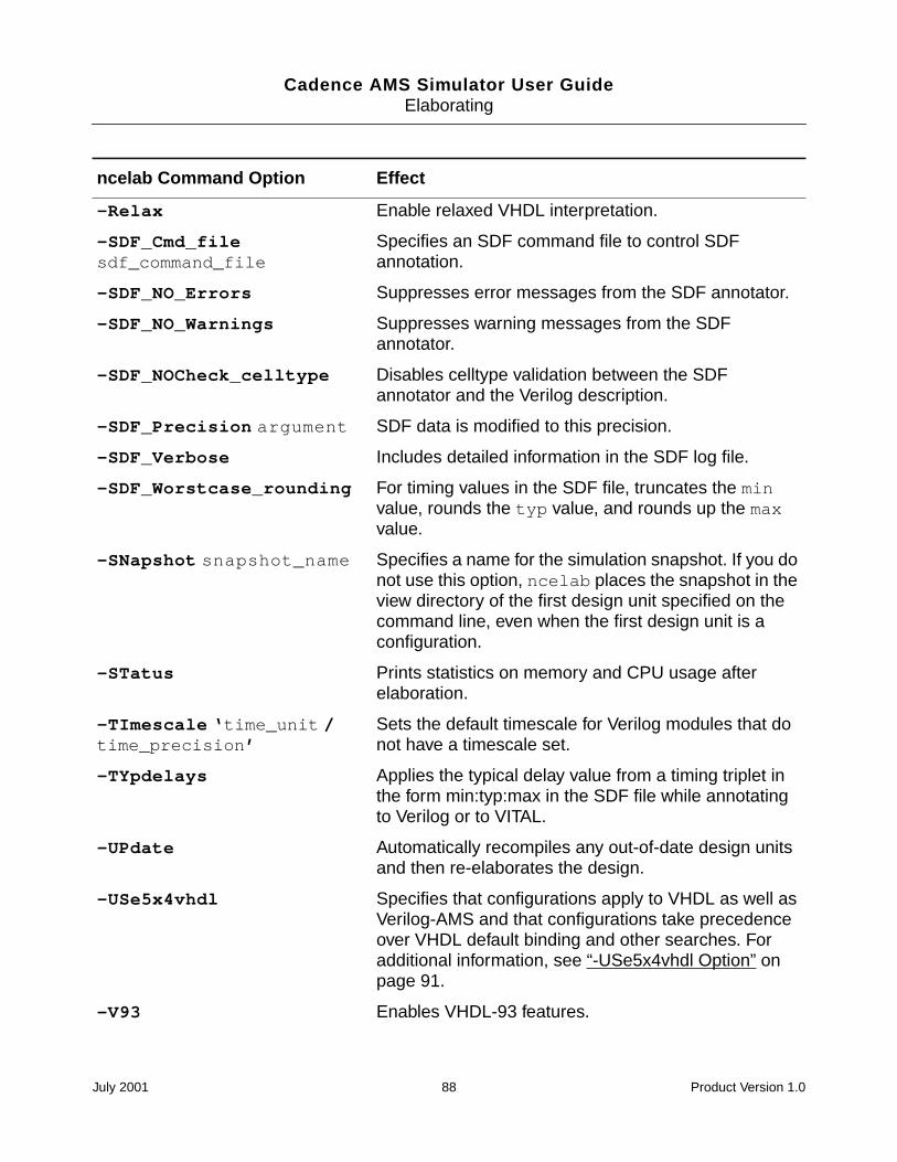
Cadence AMS Simulator User GuideElaborating
-Relax Enable relaxed VHDL interpretation.
-SDF_Cmd_filesdf_command_file
Specifies an SDF command file to control SDFannotation.
-SDF_NO_Errors Suppresses error messages from the SDF annotator.
-SDF_NO_Warnings Suppresses warning messages from the SDFannotator.
-SDF_NOCheck_celltype Disables celltype validation between the SDFannotator and the Verilog description.
-SDF_Precision argument SDF data is modified to this precision.
-SDF_Verbose Includes detailed information in the SDF log file.
-SDF_Worstcase_rounding For timing values in the SDF file, truncates the minvalue, rounds the typ value, and rounds up the maxvalue.
-SNapshot snapshot_name Specifies a name for the simulation snapshot. If you donot use this option, ncelab places the snapshot in theview directory of the first design unit specified on thecommand line, even when the first design unit is aconfiguration.
-STatus Prints statistics on memory and CPU usage afterelaboration.
-TImescale ‘time_unit /time_precision’
Sets the default timescale for Verilog modules that donot have a timescale set.
-TYpdelays Applies the typical delay value from a timing triplet inthe form min:typ:max in the SDF file while annotatingto Verilog or to VITAL.
-UPdate Automatically recompiles any out-of-date design unitsand then re-elaborates the design.
-USe5x4vhdl Specifies that configurations apply to VHDL as well asVerilog-AMS and that configurations take precedenceover VHDL default binding and other searches. Foradditional information, see “-USe5x4vhdl Option” onpage 91.
-V93 Enables VHDL-93 features.
ncelab Command Option Effect
July 2001 88 Product Version 1.0
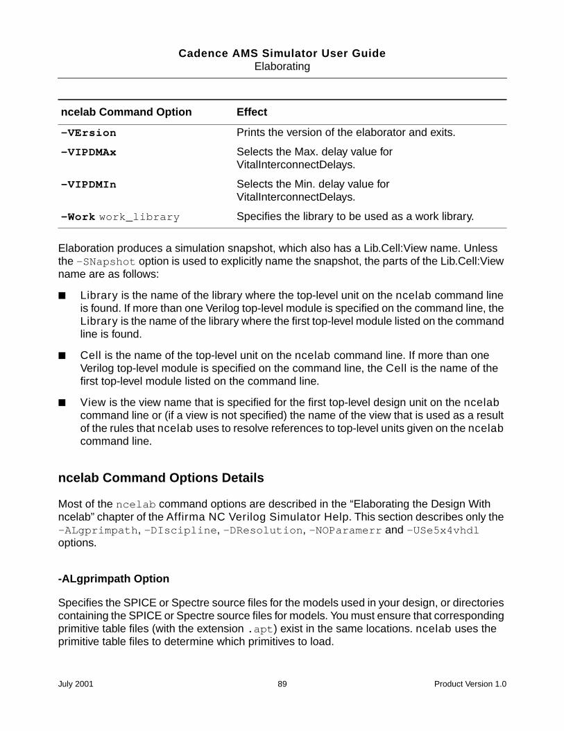
Cadence AMS Simulator User GuideElaborating
Elaboration produces a simulation snapshot, which also has a Lib.Cell:View name. Unlessthe -SNapshot option is used to explicitly name the snapshot, the parts of the Lib.Cell:Viewname are as follows:
Library is the name of the library where the top-level unit on the ncelab command lineis found. If more than one Verilog top-level module is specified on the command line, theLibrary is the name of the library where the first top-level module listed on the commandline is found.
Cell is the name of the top-level unit on the ncelab command line. If more than oneVerilog top-level module is specified on the command line, the Cell is the name of thefirst top-level module listed on the command line.
View is the view name that is specified for the first top-level design unit on the ncelabcommand line or (if a view is not specified) the name of the view that is used as a resultof the rules that ncelab uses to resolve references to top-level units given on the ncelabcommand line.
ncelab Command Options Details
Most of the ncelab command options are described in the “Elaborating the Design Withncelab” chapter of the Affirma NC Verilog Simulator Help. This section describes only the-ALgprimpath, -DIscipline, -DResolution, -NOParamerr and -USe5x4vhdloptions.
-ALgprimpath Option
Specifies the SPICE or Spectre source files for the models used in your design, or directoriescontaining the SPICE or Spectre source files for models. You must ensure that correspondingprimitive table files (with the extension .apt) exist in the same locations. ncelab uses theprimitive table files to determine which primitives to load.
-VErsion Prints the version of the elaborator and exits.
-VIPDMAx Selects the Max. delay value forVitalInterconnectDelays.
-VIPDMIn Selects the Min. delay value forVitalInterconnectDelays.
-Work work_library Specifies the library to be used as a work library.
ncelab Command Option Effect
July 2001 89 Product Version 1.0
Cadence AMS Simulator User GuideElaborating
You can also achieve the same result by defining the ALGPRIMPATH variable in the hdl.varfile. For more information, see “The hdl.var File” on page 45.
For example, assume that the file simple_cap.m contains the following Verilog-AMSdefinition. This file instantiates an analog model, my_mod_cap.
// cap model definition
simulator lang=spectreparameters base=8
model my_mod_cap capacitor c=2u tc1=1.2e-8tnom=(17 + base) w=4u l=4u cjsw=2.4e-10
The primitive table file, simple_cap.m.apt, which must be in the same directory assimple_cap.m, contains the following corresponding definition.
// primitive table file
primtableprimitive my_mod_cap;
endprimtable
You can use these definitions in a command like this one.
ncelab -algprimpath "simple_cap.m" top
You use the genalgprim utility to generate primitive table files. For more information, see“Creating an Analog Primitive Table” on page 63.
-DIscipline Option
Specifies a discipline for discrete nets for which a discipline is either not specified or cannotbe determined through discipline resolution. For example, the following command linespecifies that the logic discipline is to be used for nets that do not have a known discipline.
ncelab -discipline logic top
-DResolution Option
Specifies that the detailed discipline resolution method is to be used to determine thediscipline of nets that do not otherwise have defined disciplines. If you do not use this option,the basic discipline resolution method is used. For more information about these methods,see the “Discipline Resolution Methods” section of the “Mixed-Signal Aspects ofVerilog-AMS” chapter, in the Cadence Verilog-AMS Language Reference.
For example, the following command line specifies the use of the detailed discipline resolutionmethod.
ncelab -dresolution top
July 2001 90 Product Version 1.0
Cadence AMS Simulator User GuideElaborating
-NOParamerr Option
By default, the elaborator reports an error and stops when it encounters a value override foran undeclared parameter. Specifying -noparamerr tells the elaborator to allow undeclaredparameters to be overridden.
For example, the following command line permits overriding the values of undeclaredparameters, such as by using a defparam statement or by overriding the value when aninstance is declared.
ncelab -noparamerr top
-USe5x4vhdl Option
Specifies that configurations apply to VHDL as well as Verilog-AMS, and that configurationstake precedence over VHDL default binding and other searches. However, any configurationrules included in the VHDL source, such as use clauses, take precedence over theconfiguration.
Be aware, that if you plan to use a configuration, your design units must be compiled with the-USe5x command line option. For more information, see “Using a Configuration” on page 25.
Example ncelab Command Lines
The following command includes the -MEssages option, which prints elaborator messages.
% ncelab -messages top
The following example includes the -LOGfile option, which renames the log file fromncelab.log to top_elab.log.
% ncelab -messages -logfile top_elab.log top
In the following example, the -ERrormax option tells the elaborator to abort after 10 errors.
% ncelab -messages -errormax 10 top
The following example uses the -File option to include a file called ncelab.args, whichcontains a set of elaborator command-line options.
% ncelab -file ncelab.args top
The following example uses the -SDF_Cmd_file option to specify an SDF command filecalled dcache_sdf.cmd. Using this option overrides the automatic SDF annotation toVerilog portions of the design. The command file contains commands that control SDFannotation. For details on SDF annotation, see the “SDF Timing Annotation” chapter, in theAffirma NC Verilog Simulator Help.
July 2001 91 Product Version 1.0
Cadence AMS Simulator User GuideElaborating
% ncelab -messages -sdf_cmd_file dcache_sdf.cmd top
The following example illustrates how to use the -ALgprimpath option to elaborate modulesthat use primitives. The directory that holds simp_res.m must have another file namedsimp_res.m.apt, which is a primitive table.
% ncelab -algprimpath "simp_res.m" 2bit_adder.v
The following example illustrates how to use a configuration file. In this example, theconfiguration file is the first design unit specified on the command line, so the simulationsnapshot, by default, goes into the view directory of the configuration. As a result, there is noneed to explicitly specify the snapshot directory with the -SNapshot option.
% ncelab -use5x4vhdl myconfig.cfg another.top
hdl.var Variables
This section lists the hdl.var variables used by ncelab. For additional information, see the“hdl.var Variables” section of the “Elaborating the Design with ncelab” chapter, in the AffirmaNC Verilog Simulator Help.
ALGPRIMPATH Variable
This variable specifies the SPICE or Spectre source files for the models used in your design,or directories containing the SPICE or Spectre source files for models. You must ensure that
hdl.var Variables Usedby ncelab Description
ALGPRIMPATH Specifies the SPICE or Spectre source files for the modelsused in your design, or directories containing the SPICE orSpectre source files for models. For additional information, see“ALGPRIMPATH Variable” on page 92.
NCELABOPTS Sets elaborator command-line options.
LIB_MAP Specifies the list of libraries to search, and the order in which tosearch them, when the elaborator resolves instances.
VIEW_MAP Specifies the list of views to search, and the order in which tosearch them, when resolving instances.
WORK Specifies the work library. The elaborator uses this variableonly for VHDL default binding.
July 2001 92 Product Version 1.0
Cadence AMS Simulator User GuideElaborating
corresponding primitive table files (with the extension .apt) exist in the same locations.ncelab uses the primitive table files to determine which primitives to load.
For example, assume that the file simple_cap.m contains the following Verilog-AMSdefinition. This file instantiates an analog model, my_mod_cap.
// cap model definition
simulator lang=spectreparameters base=8
model my_mod_cap capacitor c=2u tc1=1.2e-8 tnom=(17 + base) w=4u l=4u cjsw=2.4e-10
The primitive table file, simple_cap.m.apt, which must be in the same directory assimple_cap.m, contains the following corresponding definition.
// primitive table file
primtableprimitive my_mod_cap;
endprimtable
You can use a statement like the following to define an hdl.var variable that uses thesedefinitions.
DEFINE ALGPRIMPATH "simple_cap.m"
Usually, you use the genalgprim utility to generate primitive table files but you can alsodevelop primitive table files by hand. For more information, see “Creating an Analog PrimitiveTable” on page 63.
How Modules and UDPs Are Resolved During Elaboration
One of the most important operations that occurs during elaboration is binding (or linking).Binding is the process of selecting which design units are instantiated at each location in thehierarchy. Each module or UDP that is instantiated in another, higher-level, module is boundto a particular Lib.Cell:View.
The binding rules described in the cross-references given below do not apply to the top-levelmodules that you specify on the command line. See “Overview” on page 82 for informationon the rules for selecting a Lib.Cell:View for top-level modules.
The following topics are discussed in the “Elaborating the Design With ncelab” chapter, in theAffirma NC Verilog Simulator Help.
The default binding mechanism. See “The Default Binding Mechanism” section.
The -Binding option, which is used to force the binding of a cell to a particular libraryand view. See “The -binding Option” section.
July 2001 93 Product Version 1.0
Cadence AMS Simulator User GuideElaborating
The `uselib compiler directive, which overrides the default binding mechanism and allcommand-line options. See “The ‘uselib Compiler Directive” section.
Enabling Read, Write, or Connectivity Access to DigitalSimulation Objects
By default, the elaborator enables full access to digital simulation objects in the VHDL portionof a design. In addition, you always have full access to analog objects.
However, the elaborator marks all digital objects in a Verilog-AMS design as having no reador write access, and disables access to connectivity (load and driver) information. Turning offthese three forms of access allows the elaborator to perform a set of optimizations that candramatically improve the performance of the digital solver.
The only exceptions to this default mode are digital objects that are used as arguments touser-defined system tasks or functions. These objects are automatically given read, write,and connectivity access. By default, no access is given to objects that are used as argumentsto built-in system tasks or functions. Using a construct that does not have a value (a moduleinstance, for example) as an argument has no effect on access capabilities.
Generating a snapshot with limited visibility into simulation constructs and running thesimulation in regression mode has significant performance advantages. However, turning offaccess to the HDL data structures imposes the following limitation: You cannot accesssimulation objects from a point outside the HDL code, through Tcl commands or through PLI.
The following topics are discussed in the “Enabling Read, Write, or Connectivity Access toSimulation Objects” section of the “Elaborating the Design With ncelab” chapter, in theAffirma NC Verilog Simulator Help.
The limitations imposed by running in regression mode.
How to turn on read, write, and connectivity access by using the following elaborator(ncelab) command-line options:
-ACCEss
Use this option to specify the access capability for all objects in the design. See the“Using -access to Specify Read/Write/Connectivity Access” section.
-AFile
Use this option to include an access file, in which you specify the access capabilityfor particular instances and portions of the design. See the “Using -afile to Includean Access File” section.
July 2001 94 Product Version 1.0
Cadence AMS Simulator User GuideElaborating
See the “Generating an Access File” section for information on how to automaticallygenerate an access file.
General guidelines for setting access control. See the “Guidelines for Access Control”section.
Selecting a Delay Mode
Delay modes let you alter the delay values specified in your models by using command-lineoptions and compiler directives. You can ignore all delays specified in your model or replaceall delays with a value of one simulation time unit. You can also replace delay values inselected portions of the model.
You can specify delay modes on a global basis or on a module basis. If you assign a specificdelay mode to a module, all instances of that module simulate in that mode. The delay modeof each module is determined at elaboration time and cannot be altered dynamically.
For detailed guidance on selecting and using delay modes, see the “Selecting a Delay Mode”section of the “Elaborating the Design With ncelab” chapter, in the Affirma NC VerilogSimulator Help.
Setting Pulse Controls
In the AMS simulator, both module path delays and interconnect delays are simulated astransport delays by default. There is no command-line option to enable the transport delayalgorithm. You must, however, set pulse control limits to see transport delay behavior. If youdo not set pulse control limits, the limits are set equal to the delay by default, and no pulseshaving a shorter duration than the delay pass through.
Full pulse control is available for both types of delays. You can:
Set global pulse control for both module path delays and interconnect delays.
Set global pulse limits for module path delays and interconnect delays separately in thesame simulation.
Narrow the scope of module path pulse control to a specific module or to particular pathswithin modules using the PATHPULSE$ specparam.
Specify whether you want to use On-Event or On-Detect pulse filtering.
For detailed information about these topics, see the “Setting Pulse Controls” section of the“Elaborating the Design With ncelab” chapter, in the Affirma NC Verilog Simulator Help.
July 2001 95 Product Version 1.0
Cadence AMS Simulator User Guide
8Specifying Controls for the Analog Solver
Netlists used for analog-only simulators, such as Spectre, serve a number of purposes,including: instantiating components, setting initial conditions, defining models, and specifyinganalyses. In the Cadence AMS simulator, instantiation and model specification are separatedfrom the simulator controls and some of the analog controls are separated from the rest ofthe simulation controls. As a result, the primary way of controlling the analog solver is todefine an analog simulation control file. The statements you can use in the analog simulationcontrol file are listed in the following sections.
Language Mode (lang) on page 97
Immediate Set Options (options) on page 97
Initial Guess (nodeset) on page 100
Transient Analysis (tran) on page 100
Initial Conditions (ic) on page 102
Displaying and Saving Information (info) on page 102
July 2001 96 Product Version 1.0
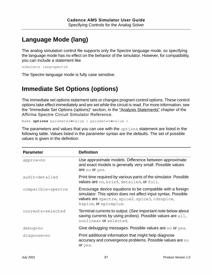
Cadence AMS Simulator User GuideSpecifying Controls for the Analog Solver
Language Mode (lang)
The analog simulation control file supports only the Spectre language mode, so specifyingthe language mode has no effect on the behavior of the simulator. However, for compatibility,you can include a statement like
simulator lang=spectre
The Spectre language mode is fully case sensitive.
Immediate Set Options (options)
The immediate set options statement sets or changes program control options. These controloptions take effect immediately and are set while the circuit is read. For more information, seethe “Immediate Set Options (options)” section, in the “Analysis Statements” chapter of theAffirma Spectre Circuit Simulator Reference.
Name options parameter=value parameter=value
The parameters and values that you can use with the options statement are listed in thefollowing table. Values listed in the parameter syntax are the defaults. The set of possiblevalues is given in the definition.
Parameter Definition
approx=no Use approximate models. Difference between approximateand exact models is generally very small. Possible valuesare no or yes.
audit=detailed Print time required by various parts of the simulator. Possiblevalues are no, brief, detailed, or full.
compatible=spectre Encourage device equations to be compatible with a foreignsimulator. This option does not affect input syntax. Possiblevalues are spectre, spice2, spice3, cdsspice,hspice, or spiceplus.
currents=selected Terminal currents to output. (See important note below aboutsaving currents by using probes). Possible values are all,nonlinear or selected.
debug=no Give debugging messages. Possible values are no or yes.
diagnose=no Print additional information that might help diagnoseaccuracy and convergence problems. Possible values are noor yes.
July 2001 97 Product Version 1.0
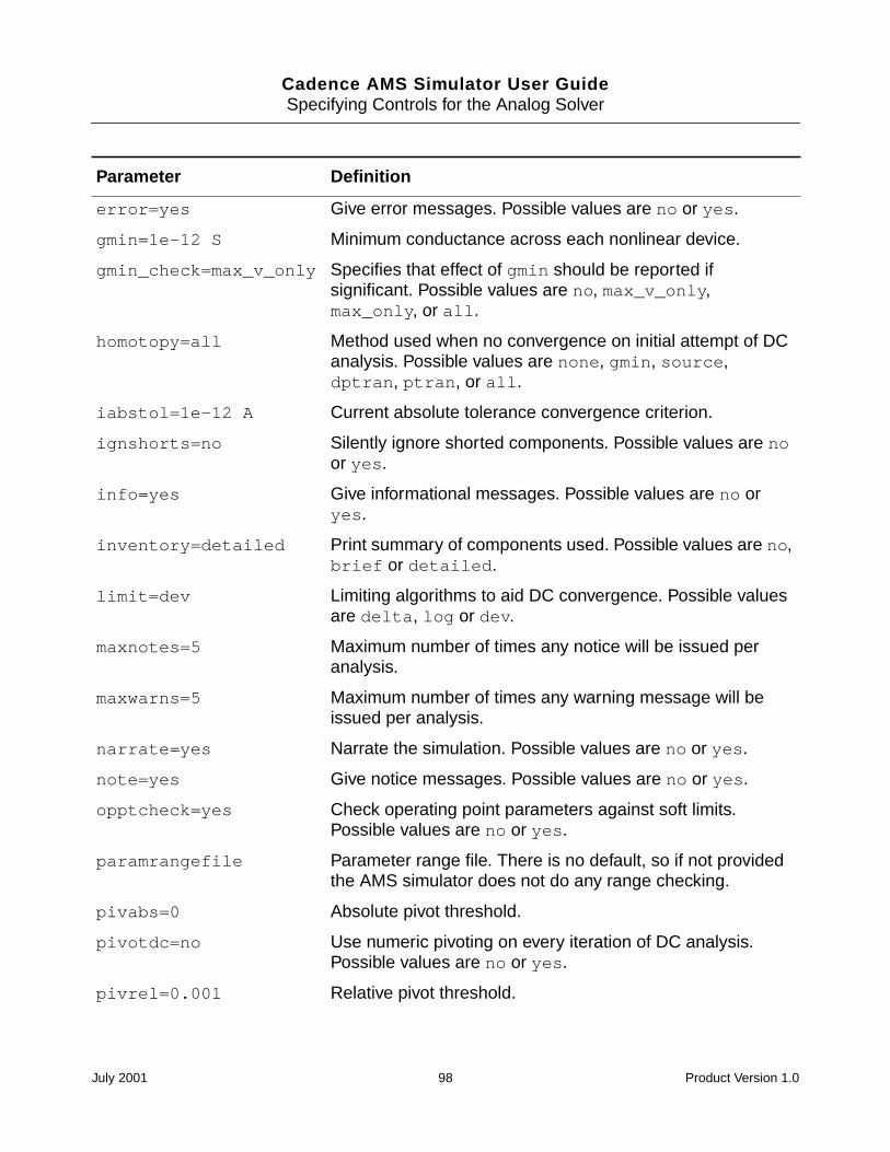
Cadence AMS Simulator User GuideSpecifying Controls for the Analog Solver
error=yes Give error messages. Possible values are no or yes.
gmin=1e-12 S Minimum conductance across each nonlinear device.
gmin_check=max_v_only Specifies that effect of gmin should be reported ifsignificant. Possible values are no, max_v_only,max_only, or all.
homotopy=all Method used when no convergence on initial attempt of DCanalysis. Possible values are none, gmin, source,dptran, ptran, or all.
iabstol=1e-12 A Current absolute tolerance convergence criterion.
ignshorts=no Silently ignore shorted components. Possible values are noor yes.
info=yes Give informational messages. Possible values are no oryes.
inventory=detailed Print summary of components used. Possible values are no,brief or detailed.
limit=dev Limiting algorithms to aid DC convergence. Possible valuesare delta, log or dev.
maxnotes=5 Maximum number of times any notice will be issued peranalysis.
maxwarns=5 Maximum number of times any warning message will beissued per analysis.
narrate=yes Narrate the simulation. Possible values are no or yes.
note=yes Give notice messages. Possible values are no or yes.
opptcheck=yes Check operating point parameters against soft limits.Possible values are no or yes.
paramrangefile Parameter range file. There is no default, so if not providedthe AMS simulator does not do any range checking.
pivabs=0 Absolute pivot threshold.
pivotdc=no Use numeric pivoting on every iteration of DC analysis.Possible values are no or yes.
pivrel=0.001 Relative pivot threshold.
Parameter Definition
July 2001 98 Product Version 1.0
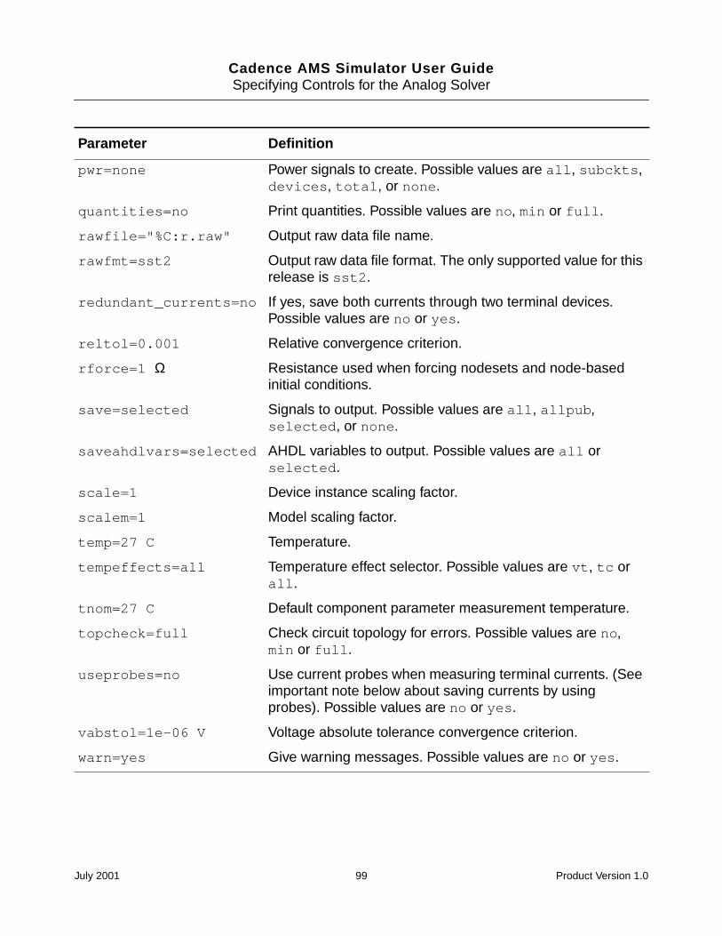
Cadence AMS Simulator User GuideSpecifying Controls for the Analog Solver
pwr=none Power signals to create. Possible values are all, subckts,devices, total, or none.
quantities=no Print quantities. Possible values are no, min or full.
rawfile="%C:r.raw" Output raw data file name.
rawfmt=sst2 Output raw data file format. The only supported value for thisrelease is sst2.
redundant_currents=no If yes, save both currents through two terminal devices.Possible values are no or yes.
reltol=0.001 Relative convergence criterion.
rforce=1 Ω Resistance used when forcing nodesets and node-basedinitial conditions.
save=selected Signals to output. Possible values are all, allpub,selected, or none.
saveahdlvars=selected AHDL variables to output. Possible values are all orselected.
scale=1 Device instance scaling factor.
scalem=1 Model scaling factor.
temp=27 C Temperature.
tempeffects=all Temperature effect selector. Possible values are vt, tc orall.
tnom=27 C Default component parameter measurement temperature.
topcheck=full Check circuit topology for errors. Possible values are no,min or full.
useprobes=no Use current probes when measuring terminal currents. (Seeimportant note below about saving currents by usingprobes). Possible values are no or yes.
vabstol=1e-06 V Voltage absolute tolerance convergence criterion.
warn=yes Give warning messages. Possible values are no or yes.
Parameter Definition
July 2001 99 Product Version 1.0
Cadence AMS Simulator User GuideSpecifying Controls for the Analog Solver
Initial Guess (nodeset)
You use the nodeset statement to supply estimates of solutions that aid convergence or biasthe simulation toward a given solution. You can use nodesets for all DC and initial transientanalysis solutions. If you have more than one nodeset statement in the input, the simulatorcollects the information. For more information, see the “Node Sets (nodeset)” section, in the“Spectre Syntax” chapter of the Affirma Spectre Circuit Simulator Reference.
nodeset node=value node=value
Each node is a signal. Each signal is a value associated with a topological node of the circuitor with some other unknown that is solved by the simulator. For example, the unknown valuemight be the current through an inductor or the voltage of the internal node in a diode
For example, the following statement
nodeset n1=0 out=1 OpAmp1.comp=5 L1:t1=1.0u
specifies that node n1 should be about 0V, node out should be about 1V, node comp insubcircuit OpAmp1 should be about 5V, and the current through the first terminal of L1 shouldbe about 1uA.
Transient Analysis (tran)
The tran statement computes the transient response of a circuit over the interval from start tostop. The initial condition is taken to be the DC steady-state solution, if not otherwise given.For more information, see the “Transient Analysis (tran)” section, in the “Analysis Statements”chapter of the Affirma Spectre Circuit Simulator Reference.
Name tran parameter=value parameter=value
The parameters and values that you can use with the tran statement are listed in thefollowing table.
Parameter Definition
annotate=sweep Degree of annotation.
circuitage (Years) Stress time. Age of the circuit used to simulate hot-electron degradation of MOSFET and BSIM circuits.
cmin=0 F Minimum capacitance from each node to ground.
errpreset=moderate Selects a reasonable collection of parameter settings.Possible values are conservative, moderate orliberal.
July 2001 100 Product Version 1.0
Cadence AMS Simulator User GuideSpecifying Controls for the Analog Solver
flushofftime (s) Time to stop flushing outputs.
flushpoints Flush outputs after number of calculated points.
flushtime (s) Flush outputs after real time has elapsed.
ic=all What should be used to set initial condition. Possiblevalues are dc, node, dev, or all.
infotimes=[...] s Times when operating points should be saved.
lteratio Ratio used to compute LTE tolerances from Newtontolerance. Default derived from errpreset.
maxiters=5 Maximum number of iterations per time step.
maxstep (s) Maximum time step. Default derived from errpreset.
method Integration method. Default derived from errpreset.Possible values are euler, trap, traponly, gear2,gear2only, or trapgear2.
oppoint=no Should operating point information be computed for initialtimestep, and if so, where should it be sent. Possiblevalues are no, screen, logfile, or rawfile.
readic File that contains initial condition.
readns File that contains estimate of initial transient solution.
relref Reference used for the relative convergence criteria.Default derived from errpreset. Possible values arepointlocal, alllocal, sigglobal, or allglobal.
restart=yes Do not use previous DC solution as initial guess. Possiblevalues are no or yes.
save Signals to output. Possible values are all, allpub,selected, or none.
skipcount Save only one of every skipcount points.
skipdc=no If yes, there will be no dc analysis for transient. Possiblevalues are no, yes, waveless, rampup, or autodc.
skipstart=starttime s The time to start skipping output data.
start=0 s Start time. In this release, the only supported value iszero.
Parameter Definition
July 2001 101 Product Version 1.0
Cadence AMS Simulator User GuideSpecifying Controls for the Analog Solver
Initial Conditions (ic)
You use the ic statement to provide initial conditions for nodes in the transient analysis.When there are multiple statements in the input, the information provided in all theoccurrences is collected. Initial conditions are accepted only for inductor currents and fornode voltages where the nodes have a path of capacitors to ground. For more information,see the “Initial Conditions (ic)” section, in the “Spectre Syntax” chapter of the AffirmaSpectre Circuit Simulator Reference.
ic node=value node=value
Each node is a signal. Each signal is a value associated with a topological node of the circuitor with some other unknown that is solved by the simulator. For example, the unknown valuemight be the current through an inductor or the voltage of the internal node in a diode.
For example, the following statement
ic n7=0 out=1 OpAmp1.comp=5 L1:t1=1.0u
specifies that node n7 is to start at 0V, node out is to start at 1V, node comp in subcircuitOpAmp1 is to start at 5V, and the current through the first terminal of L1 is to start at 1uA.
Displaying and Saving Information (info)
With the info statement, you can output several kinds of information about circuits andcomponents. You can use various filters to specify what information is output. You can create
stats=no Analysis statistics. Possible values are no or yes.
step=0.001 (stop-start)s
Minimum time step used by the simulator solely tomaintain the aesthetics of the computed waveforms.
stop (s) Stop time.
strobedelay=0 s The delay (phase shift) between the skipstart time andthe first strobe point.
strobeperiod (s) The output strobe interval (in seconds of transient time).
title Analysis title.
write File to which initial transient solution is to be written.
writefinal File to which final transient solution is to be written.
Parameter Definition
July 2001 102 Product Version 1.0
Cadence AMS Simulator User GuideSpecifying Controls for the Analog Solver
a listing of model, instance, temperature- dependent, input, output, and operating pointparameters. You can generate a summary of the minimum and maximum parameter valuesand you can request that the simulator provide a node-to-terminal map or a terminal-to-nodemap.
Name info parameter=value parameter=value
For parameter, you can substitute what, where, file, save, extremes, or title, asdescribed in the following sections.
what
You can use the what parameter of the info statement to specify what parameters are to beprinted. You can give the what parameter the following settings:
Settings forwhat Action
none Does not print any parameters.
inst Print out information about instances.
models Print out information about models.
input Print out information about inputs.
output Print out information about outputs.
nodes The output is a terminal-to-node map
all Lists input and output parameter values
terminal The output is a node-to-terminal map
oppoint Print out information about operating points.
captab Print out information about capacitance tables.
July 2001 103 Product Version 1.0
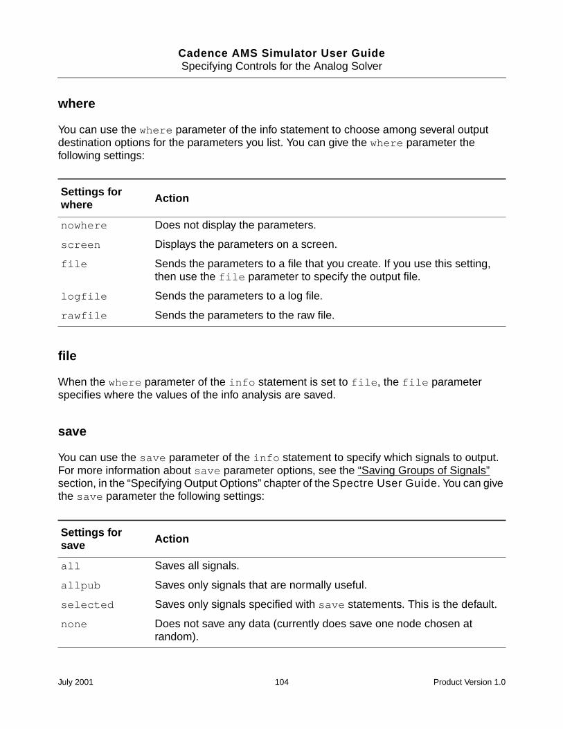
Cadence AMS Simulator User GuideSpecifying Controls for the Analog Solver
where
You can use the where parameter of the info statement to choose among several outputdestination options for the parameters you list. You can give the where parameter thefollowing settings:
file
When the where parameter of the info statement is set to file, the file parameterspecifies where the values of the info analysis are saved.
save
You can use the save parameter of the info statement to specify which signals to output.For more information about save parameter options, see the “Saving Groups of Signals”section, in the “Specifying Output Options” chapter of the Spectre User Guide. You can givethe save parameter the following settings:
Settings forwhere Action
nowhere Does not display the parameters.
screen Displays the parameters on a screen.
file Sends the parameters to a file that you create. If you use this setting,then use the file parameter to specify the output file.
logfile Sends the parameters to a log file.
rawfile Sends the parameters to the raw file.
Settings forsave Action
all Saves all signals.
allpub Saves only signals that are normally useful.
selected Saves only signals specified with save statements. This is the default.
none Does not save any data (currently does save one node chosen atrandom).
July 2001 104 Product Version 1.0
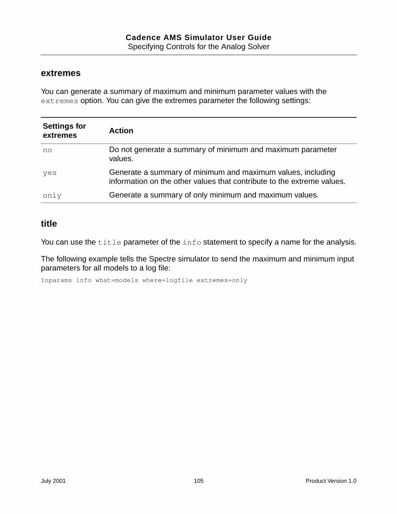
Cadence AMS Simulator User GuideSpecifying Controls for the Analog Solver
extremes
You can generate a summary of maximum and minimum parameter values with theextremes option. You can give the extremes parameter the following settings:
title
You can use the title parameter of the info statement to specify a name for the analysis.
The following example tells the Spectre simulator to send the maximum and minimum inputparameters for all models to a log file:
Inparams info what=models where=logfile extremes=only
Settings forextremes Action
no Do not generate a summary of minimum and maximum parametervalues.
yes Generate a summary of minimum and maximum values, includinginformation on the other values that contribute to the extreme values.
only Generate a summary of only minimum and maximum values.
July 2001 105 Product Version 1.0
Cadence AMS Simulator User Guide
9Simulating
This chapter contains the following sections:
Overview on page 107
ncsim Command Syntax and Options on page 108
hdl.var Variables on page 112
Running the Simulator on page 112
Starting a Simulation on page 113
Updating Design Changes When You Run the Simulator on page 114
Providing Interactive Commands from a File on page 114
Exiting the Simulation on page 115
July 2001 106 Product Version 1.0
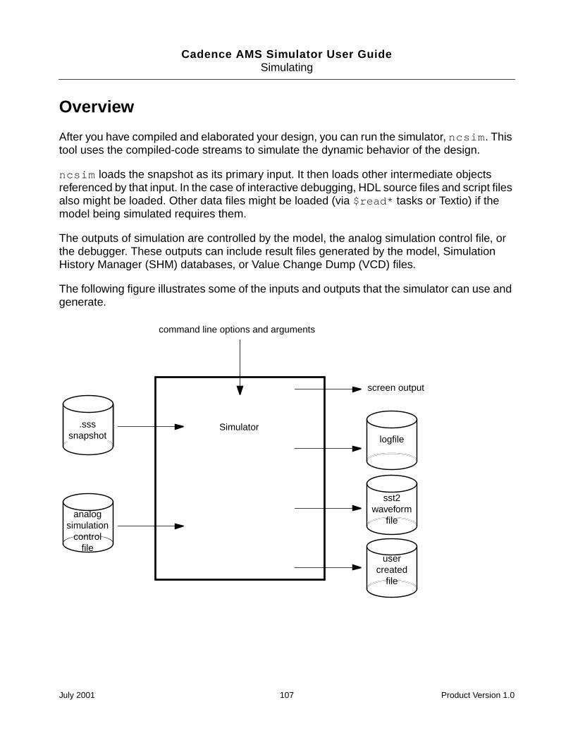
Cadence AMS Simulator User GuideSimulating
Overview
After you have compiled and elaborated your design, you can run the simulator, ncsim. Thistool uses the compiled-code streams to simulate the dynamic behavior of the design.
ncsim loads the snapshot as its primary input. It then loads other intermediate objectsreferenced by that input. In the case of interactive debugging, HDL source files and script filesalso might be loaded. Other data files might be loaded (via $read* tasks or Textio) if themodel being simulated requires them.
The outputs of simulation are controlled by the model, the analog simulation control file, orthe debugger. These outputs can include result files generated by the model, SimulationHistory Manager (SHM) databases, or Value Change Dump (VCD) files.
The following figure illustrates some of the inputs and outputs that the simulator can use andgenerate.
command line options and arguments
.ssssnapshot
screen output
logfile
usercreated
file
analogsimulation
controlfile
sst2waveform
file
Simulator
July 2001 107 Product Version 1.0
Cadence AMS Simulator User GuideSimulating
ncsim Command Syntax and Options
This section briefly describes the syntax and options for the ncsim command. For additionalinformation, see the “Simulating Your Design With ncsim” chapter, in the Affirma NC VerilogSimulator Help.
ncsim [options] [Lib.]Cell[:View]
The Lib, Cell, and View together identify the snapshot. (Specifying the snapshot alsoautomatically specifies the SSI, which has the same name.) You can specify the options andthe snapshot argument in any order provided that the parameters to an option immediatelyfollow the option.
Notice that you must specify at least the cell for the snapshot.
If a snapshot with the same name exists in more than one library, the easiest (andrecommended) thing to do is to specify both the cell and the library on the command line.
If there are multiple views that contain snapshots, the easiest (and recommended) thingto do is to specify both the cell and the view on the command line.
If you do not specify a library or a view, the simulator uses a set of rules to resolve thesnapshot reference on the command line. For more information, see “Rules for Resolving theSnapshot Reference” in the “Simulating Your Design With ncsim” chapter of the Affirma NCVerilog Simulator Help. See “Overview” on page 82, for information on how ncelabnames snapshots.
You can enter ncsim command options in upper or lower case and abbreviate them to theshortest unique string. In the following table, the shortest unique string is indicated withcapital letters.
ncsim Command Option Effect
-AMslic Directs the AMS simulator to use a license that allowsthe simulation of Verilog-AMS constructs. For moreinformation, see “-AMslic Option” on page 111.
-ANalogcontrolcontrol_file
Specifies the analog simulation control file to use. Foradditional information, see -ANalogcontrol Option onpage 111.
-APPEND_Key Appends command input from multiple runs of ncsimto one key file.
-APPEND_Log Appends log data from multiple runs of ncsim to onelog file.
July 2001 108 Product Version 1.0
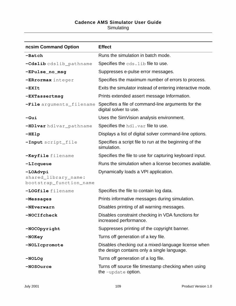
Cadence AMS Simulator User GuideSimulating
-Batch Runs the simulation in batch mode.
-Cdslib cdslib_pathname Specifies the cds.lib file to use.
-EPulse_no_msg Suppresses e-pulse error messages.
-ERrormax integer Specifies the maximum number of errors to process.
-EXIt Exits the simulator instead of entering interactive mode.
-EXTassertmsg Prints extended assert message Information.
-File arguments_filename Specifies a file of command-line arguments for thedigital solver to use.
-Gui Uses the SimVision analysis environment.
-HDlvar hdlvar_pathname Specifies the hdl.var file to use.
-HElp Displays a list of digital solver command-line options.
-Input script_file Specifies a script file to run at the beginning of thesimulation.
-Keyfile filename Specifies the file to use for capturing keyboard input.
-LIcqueue Runs the simulation when a license becomes available.
-LOAdvpishared_library_name:bootstrap_function_name
Dynamically loads a VPI application.
-LOGfile filename Specifies the file to contain log data.
-Messages Prints informative messages during simulation.
-NEverwarn Disables printing of all warning messages.
-NOCIfcheck Disables constraint checking in VDA functions forincreased performance.
-NOCOpyright Suppresses printing of the copyright banner.
-NOKey Turns off generation of a key file.
-NOLIcpromote Disables checking out a mixed-language license whenthe design contains only a single language.
-NOLOg Turns off generation of a log file.
-NOSOurce Turns off source file timestamp checking when usingthe -update option.
ncsim Command Option Effect
July 2001 109 Product Version 1.0
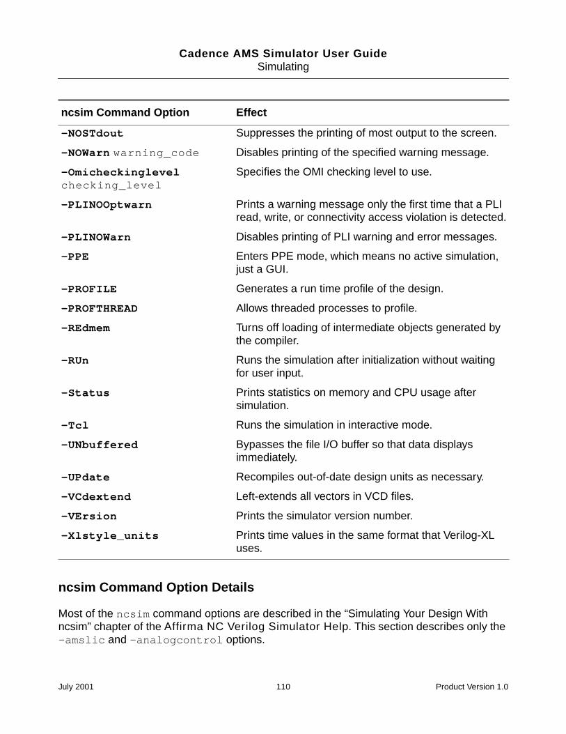
Cadence AMS Simulator User GuideSimulating
ncsim Command Option Details
Most of the ncsim command options are described in the “Simulating Your Design Withncsim” chapter of the Affirma NC Verilog Simulator Help. This section describes only the-amslic and -analogcontrol options.
-NOSTdout Suppresses the printing of most output to the screen.
-NOWarn warning_code Disables printing of the specified warning message.
-Omicheckinglevelchecking_level
Specifies the OMI checking level to use.
-PLINOOptwarn Prints a warning message only the first time that a PLIread, write, or connectivity access violation is detected.
-PLINOWarn Disables printing of PLI warning and error messages.
-PPE Enters PPE mode, which means no active simulation,just a GUI.
-PROFILE Generates a run time profile of the design.
-PROFTHREAD Allows threaded processes to profile.
-REdmem Turns off loading of intermediate objects generated bythe compiler.
-RUn Runs the simulation after initialization without waitingfor user input.
-Status Prints statistics on memory and CPU usage aftersimulation.
-Tcl Runs the simulation in interactive mode.
-UNbuffered Bypasses the file I/O buffer so that data displaysimmediately.
-UPdate Recompiles out-of-date design units as necessary.
-VCdextend Left-extends all vectors in VCD files.
-VErsion Prints the simulator version number.
-Xlstyle_units Prints time values in the same format that Verilog-XLuses.
ncsim Command Option Effect
July 2001 110 Product Version 1.0
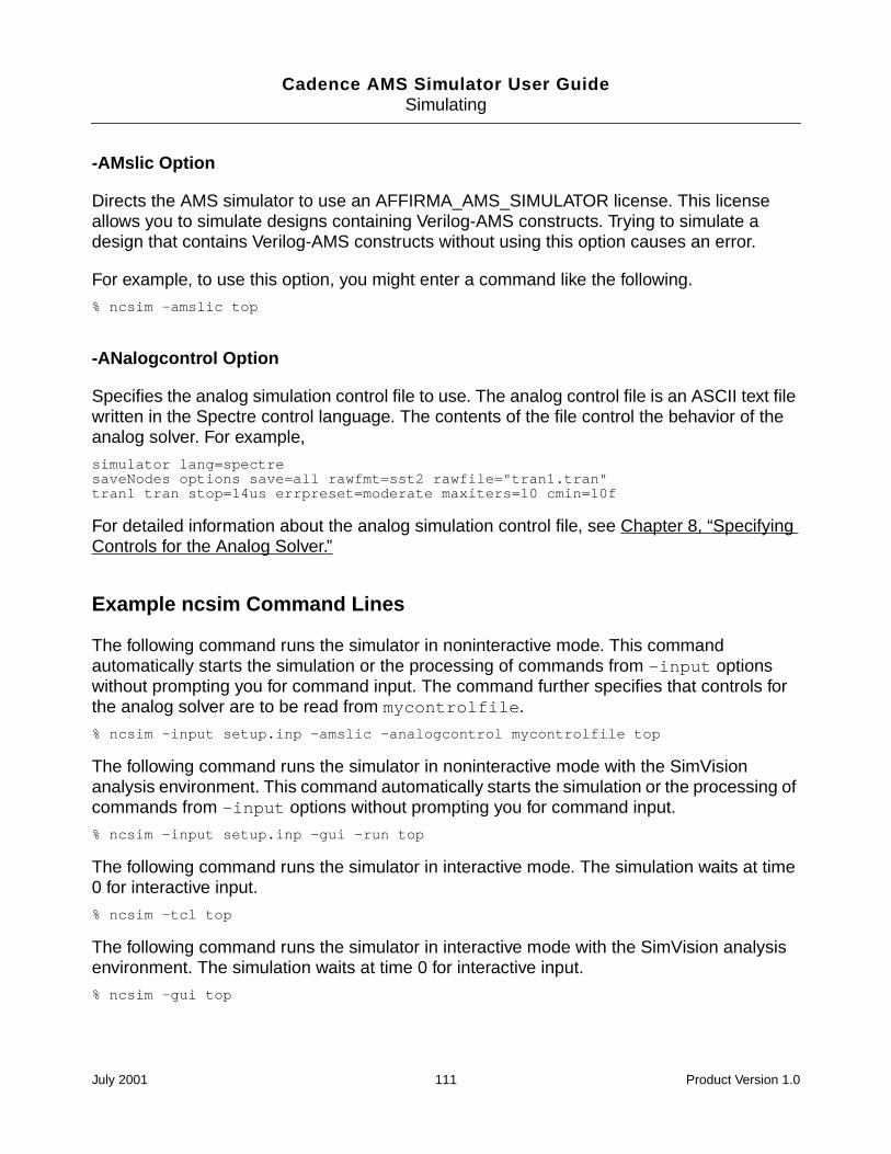
Cadence AMS Simulator User GuideSimulating
-AMslic Option
Directs the AMS simulator to use an AFFIRMA_AMS_SIMULATOR license. This licenseallows you to simulate designs containing Verilog-AMS constructs. Trying to simulate adesign that contains Verilog-AMS constructs without using this option causes an error.
For example, to use this option, you might enter a command like the following.
% ncsim -amslic top
-ANalogcontrol Option
Specifies the analog simulation control file to use. The analog control file is an ASCII text filewritten in the Spectre control language. The contents of the file control the behavior of theanalog solver. For example,
simulator lang=spectresaveNodes options save=all rawfmt=sst2 rawfile="tran1.tran"tran1 tran stop=14us errpreset=moderate maxiters=10 cmin=10f
For detailed information about the analog simulation control file, see Chapter 8, “SpecifyingControls for the Analog Solver.”
Example ncsim Command Lines
The following command runs the simulator in noninteractive mode. This commandautomatically starts the simulation or the processing of commands from -input optionswithout prompting you for command input. The command further specifies that controls forthe analog solver are to be read from mycontrolfile.
% ncsim -input setup.inp -amslic -analogcontrol mycontrolfile top
The following command runs the simulator in noninteractive mode with the SimVisionanalysis environment. This command automatically starts the simulation or the processing ofcommands from -input options without prompting you for command input.
% ncsim -input setup.inp -gui -run top
The following command runs the simulator in interactive mode. The simulation waits at time0 for interactive input.
% ncsim -tcl top
The following command runs the simulator in interactive mode with the SimVision analysisenvironment. The simulation waits at time 0 for interactive input.
% ncsim -gui top
July 2001 111 Product Version 1.0
Cadence AMS Simulator User GuideSimulating
The following command uses the -logfile option to rename the log file from the default(ncsim.log) to top.log.
% ncsim -messages -run -logfile top.log top
The following command uses -errormax 10 to tell the simulator to stop after 10 errors.
% ncsim -errormax 10 top
The following command uses the -file option to include a file called top.vc, whichincludes a set of command line options, such as -messages, -nocopyright, -logfile,and -errormax.
% ncsim -file top.vc top
The following command uses the -input option to source the file top.inp at initialization.This file contains a sequence of simulator (Tcl) commands.
% ncsim -input top.inp top
The following command uses the -keyfile option to specify that the name of the key fileis top.key instead of the default ncsim.key. You could use this key file to reproduce aninteractive session by using the file name top.key as the argument to the -input option.
% ncsim -tcl -keyfile top.key top
hdl.var Variables
The following variables are used by the AMS Simulator:
NCSIMOPTS
Sets simulator command-line options. A snapshot name can also be included.
For example,
DEFINE NCSIMOPTS -messages
WORK
Specifies the default library in which to look for the snapshot. If the snapshot is not foundin this library, the rest of the libraries in the cds.lib file are searched.
See “The hdl.var File” on page 45 for more information on the hdl.var file.
Running the Simulator
You can run the simulator (ncsim) in two modes:
July 2001 112 Product Version 1.0
Cadence AMS Simulator User GuideSimulating
Noninteractive mode
Automatically starts the simulation or the processing of commands from -inputoptions without prompting you for command input. For detailed guidance, see “Invokingthe Simulator in Noninteractive Mode” in the “Simulating Your Design With ncsim”chapter of the Affirma NC Verilog Simulator Help.
Interactive mode
Stops the simulation at time 0 and returns the ncsim> prompt. For detailed guidance,see “Invoking the Simulator in Interactive Mode” in the “Simulating Your Design Withncsim” chapter of the Affirma NC Verilog Simulator Help.
In either mode, you can run the simulator with or without the SimVision analysis environment.
Starting a Simulation
To start or resume a simulation:
If you are using the Tcl command-line interface, use the run command. The runcommand has several options that let you control when the simulation is to stop:
-delta Run to the beginning of the next delta cycle or to a specified deltacycle.
-next Run one behavioral statement, stepping over any subprogram calls.
-phase Run to the beginning of the next phase of the simulation cycle. Thetwo phases of a simulation cycle are signal evaluation and processexecution.
-process Run until the beginning of the next scheduled digital process or tothe beginning of the next delta cycle, whichever comes first. InVHDL, a process is a process statement. In Verilog-AMS, it is analways block, initial block, or one of several kinds ofanonymous behavior that can be scheduled to run.
Note: For the purposes of the run -process option, the analogblock is not considered a process.
-return Run until the current subprogram (task, function, procedure) returns.
-step Run one behavioral statement, stepping into subprogram calls. Thisoption does not step into function calls made by an analogstatement.
July 2001 113 Product Version 1.0
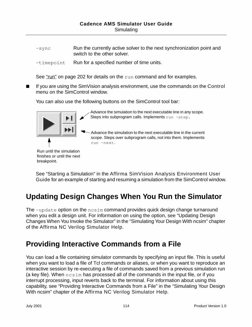
Cadence AMS Simulator User GuideSimulating
See “run” on page 202 for details on the run command and for examples.
If you are using the SimVision analysis environment, use the commands on the Controlmenu on the SimControl window.
You can also use the following buttons on the SimControl tool bar:
See “Starting a Simulation” in the Affirma SimVision Analysis Environment UserGuide for an example of starting and resuming a simulation from the SimControl window.
Updating Design Changes When You Run the Simulator
The -update option on the ncsim command provides quick design change turnaroundwhen you edit a design unit. For information on using the option, see “Updating DesignChanges When You Invoke the Simulator” in the “Simulating Your Design With ncsim” chapterof the Affirma NC Verilog Simulator Help.
Providing Interactive Commands from a File
You can load a file containing simulator commands by specifying an input file. This is usefulwhen you want to load a file of Tcl commands or aliases, or when you want to reproduce aninteractive session by re-executing a file of commands saved from a previous simulation run(a key file). When ncsim has processed all of the commands in the input file, or if youinterrupt processing, input reverts back to the terminal. For information about using thiscapability, see “Providing Interactive Commands from a File” in the “Simulating Your DesignWith ncsim” chapter of the Affirma NC Verilog Simulator Help.
-sync Run the currently active solver to the next synchronization point andswitch to the other solver.
-timepoint Run for a specified number of time units.
Run until the simulationfinishes or until the nextbreakpoint.
Advance the simulation to the next executable line in any scope.Steps into subprogram calls. Implements run -step.
Advance the simulation to the next executable line in the currentscope. Steps over subprogram calls, not into them. Implementsrun -next.
July 2001 114 Product Version 1.0
Cadence AMS Simulator User GuideSimulating
Exiting the Simulation
To exit the simulator:
If you are using the Tcl command-line interface, use either the exit command or thefinish command.
The exit command is a built-in Tcl command. It halts execution and returns control tothe operating system. For details, see the “exit” section, in the “Using the TclCommand-Line Interface” chapter of the Affirma NC Verilog Simulator Help.
The finish command also halts execution and returns control to the operating system.This command takes an optional argument that determines what type of information isdisplayed after exiting.
See “finish” on page 182 for details on the finish command.
If you are using the SimVision analysis environment, select File – Exit or enter thefinish command in the I/O region of the SimControl window.
Note: If you type the finish command in the SimControl window, the windowdisappears before you can read the information. However, the information appears in thelog file.
0 Prints nothing (same as executing finish without an argument).
1 Prints the simulation time.
2 Prints simulation time and statistics on memory and CPU usage.
July 2001 115 Product Version 1.0
Cadence AMS Simulator User Guide
10Debugging
This chapter contains the following sections:
Managing Databases on page 117
Setting and Deleting Probes on page 119
Traversing the Model Hierarchy on page 122
Setting Breakpoints on page 125
Disabling, Enabling, Deleting, and Displaying Breakpoints on page 129
Stepping Through Lines of Code on page 130
Forcing and Releasing Signal Values on page 131
Depositing Values to Signals on page 131
Displaying Information About Simulation Objects on page 132
Displaying the Drivers of Signals on page 133
Debugging Designs with Automatically-Inserted Connect Modules on page 134
Displaying Waveforms with Signalscan waves on page 134
Comparing Databases with Comparescan on page 140
Displaying Debug Settings on page 140
Setting a Default Radix on page 141
Setting Variables on page 142
Editing a Source File on page 146
Searching for a Line Number in the Source Code on page 147
Searching for a Text String in the Source Code on page 147
Configuring Your Simulation Environment on page 147
July 2001 116 Product Version 1.0
Cadence AMS Simulator User GuideDebugging
Saving and Restoring Your Simulation Environment on page 148
Creating or Deleting an Alias on page 149
Getting a History of Commands on page 149
Managing Custom Buttons on page 150
Terminology
This descriptions in this chapter use terminology that might be new to you. The terms haveto do with the way that the compiler simulates mixed analog and digital designs.
Managing Databases
You can open, close, disable, enable, and display information about databases.Althoughdatabases created by the analog simulation control file for analog waveforms might be visiblein the SimVision user interface, you cannot use Tcl commands (whether entered manually orgenerated by SimVision) to do anything with them. For example, using the databasecommand with the -close modifier on an analog database causes an error. In addition,databases opened by using Tcl commands cannot be used to store analog information.
Term Definition
analog solver The part of the AMS simulator that simulates the analogportions of a design. Some capabilities are enabled only whenthe analog solver is active. For information that will help youdetermine whether the analog or digital solver is active, seethe “Using SimVision with the AMS Simulator” chapter, in theCadence SimVision Analysis Environment User Guide.
digital solver The part of the AMS simulator that simulates the digitalportions of a design. Some capabilities are enabled only whenthe digital solver is active.
analog context The context of statements that appear in the body of ananalog block.
digital context The context of statements that appear in a location other thanan analog block.
July 2001 117 Product Version 1.0
Cadence AMS Simulator User GuideDebugging
Opening a Database
You can open two types of databases: SHM or VCD.
If you are using the Tcl command-line interface, use the database command with theoptional -open modifier to open either type of database.
Partial syntax:
database [-open] dbase_name [-shm | -vcd] [-into file_name][-default]
See the “Database” section of the “Using the Tcl Command-Line Interface” chapter, inthe Affirma NC Verilog Simulator Help for complete syntax and details on thedatabase command and for an example of using this command.
If you are using the Cadence SimVision analysis environment, choose File – SHMDatabase – Open and fill in the Open Database form to open an SHM database. Toopen a VCD database, you must use the database text command. Enter thedatabase command at the prompt in the I/O region of the SimControl window.
See “Managing Databases” in the Affirma SimVision Analysis Environment UserGuide for an example of using the commands on the SimControl window for managingyour databases.
Note: You can also open a database from a digital context with the $shm_open system taskin your Verilog-AMS code. The name of the database (not the name of the file) that is createdis preceded by an underscore character. For example, the following system task opens adatabase called _waves.shm.
$shm_open("waves.shm");
This allows you to interact with databases opened with $shm_open in the same way that youinteract with databases opened with the database command.
Displaying Information About Databases
If you are using the Tcl command-line interface, use the database command with the-show modifier to display information about databases.
Syntax:
database -show [dbase_name | pattern ...]
If you are using the Cadence SimVision analysis environment, choose Show –Databases.
July 2001 118 Product Version 1.0
Cadence AMS Simulator User GuideDebugging
Disabling a Database
If you are using the command-line interface, use the database command with the-disable modifier to temporarily disable either type of database.
Syntax:
database -disable dbase_name | pattern ...
If you are using the SimVision analysis environment, enter the database -disablecommand at the prompt in the I/O region of the SimControl window.
Enabling a Database
If you are using the command-line interface, use the database command with the-enable modifier to enable a previously disabled database.
Syntax:
database -enable dbase_name | pattern ...
If you are using the SimVision analysis environment, enter the database -enablecommand at the prompt in the I/O region of the SimControl window.
Closing a Database
If you are using the Tcl command-line interface, use the database command with the-close modifier to close either type of database.
Syntax:
database -close dbase_name | pattern ...
If you are using the SimVision analysis environment, choose File – SHM Database –Close to close a database. On the Close Database form, select the SHM database youwant to close and click the OK button.
To close a VCD database, enter the database -close command at the prompt inthe I/O region of the SimControl window.
Setting and Deleting Probes
You can save the values of objects to a database by probing them. The values contained inthe database can be viewed using a waveform viewing tool.
If you are using the Tcl command-line interface, use the probe command to set, disable,enable, delete, and display information about probes for digital objects.
July 2001 119 Product Version 1.0
Cadence AMS Simulator User GuideDebugging
See “probe” on page 185 for details on the probe command and for an example of usingthis command.
If you are using the SimVision analysis environment, choose Set – Probe to set a probe.To disable, enable, and delete a probe, choose Show – Probes and use the DebugSettings window.
See “Setting Probes” in the Affirma SimVision Analysis Environment User Guidefor an example.
Note: For Verilog-AMS, only digital objects that have read access can be probed. See“Enabling Read, Write, or Connectivity Access to Digital Simulation Objects” on page 94 fordetails on specifying access to digital simulation objects. Analog objects, regardless of theaccess they have, cannot be probed using the commands described in this section. Instead,to probe analog objects, use a save command in the analog simulation control file.
Setting a Probe
If you are using the Tcl command-line interface, use the probe command with theoptional -create modifier.
Partial syntax:
probe [-create] [object | scope_name...]-shm | -vcd | -database dbase_name
[-all][-depth n | all | to_cells][-inputs][-name probe_name][-outputs][-ports][-screen [-format format_string] [-redirect filename]
objects][-variables]
You must include one of the following options to the command: -shm, -vcd,-database.
Specifying an object or scope_name argument is optional. If you do not specify anobject or scope_name argument, you must use one of the following options:-inputs,-outputs, -ports, or -all to specify which objects to probe.
The -all option probes all declared objects within a scope(s), except for VHDLvariables. To include VHDL variables in the probe, include the -variables option(-all -variables).
If you are using the SimVision analysis environment, set probes using the Set – Probecommand.
July 2001 120 Product Version 1.0
Cadence AMS Simulator User GuideDebugging
Displaying Information About Probes
If you are using the Tcl command-line interface, use the probe command with the-show modifier to display information about the probes you have set.
Syntax:
probe -show [probe_name | pattern ...]
If you are using the SimVision analysis environment, choose Show – Probes to displayinformation about probes.
Disabling a Probe
If you are using the Tcl command-line interface, use the probe command with the-disable modifier to temporarily stop a probe.
Syntax:
probe -disable probe_name | pattern ...
If you are using the SimVision analysis environment, choose the Show – Probescommand to display the Debug Settings form and then click on the toggle button next tothe probe you want to disable.
Enabling a Probe
If you are using the Tcl command-line interface, use the probe command with the-enable modifier to enable a probe that was previously disabled.
Syntax:
probe -enable probe_name | pattern ...
If you are using the SimVision analysis environment, use the Show – Probes commandto display the Debug Settings form and then click on the toggle button next to the probeyou want to enable.
Deleting a Probe
If you are using the Tcl command-line interface, use the probe command with the-delete modifier to delete a probe.
Syntax:
probe -delete probe_name | pattern ...
July 2001 121 Product Version 1.0
Cadence AMS Simulator User GuideDebugging
If you are using the SimVision analysis environment, use the Show – Probes commandto display the Debug Settings form. Select the probe you want to delete and then clickthe Delete button.
Traversing the Model Hierarchy
The Cadence AMS simulator supports hierarchical designs by allowing models to beembedded within other models. Levels of hierarchy in a design are called scopes. To createa scope, you nest objects within design units by instantiating them. Instantiation allows onedesign unit to incorporate a copy of another into itself.
Each scope in a design hierarchy has a unique hierarchical path. For Verilog-AMS, elementsin the path are separated by a period ( . ). Paths can be:
Fully specified from the top level of the hierarchy. Full paths begin with the name of aVerilog-AMS top-level module. For example:
top.board.counter
top.vending.drinks.count_cans.in1
Relative to the current debug scope. For example, if the current debug scope istop.board, the path counter refers to a scope within the scope board, which is withinthe top-level module top.
You traverse the model hierarchy by setting the scope to an instantiated object. If you areusing the Tcl command-line interface, use the scope -set command. For example, if thecurrent debug scope is the top level, and you want to scope down one level to a scope calledboard, use the following command:
% scope -set board
If you are at the top level and want to scope down to a scope within board called counter,use the following command:
% scope -set board.counter
You can specify a full path from any debug scope. For example, if the current scope isboard:counter, you can scope up to the top level (module top) with the followingcommand:
% scope -set top
The scope command has several options besides -set. These options let you:
Describe the items declared within a scope (-describe).
Display the drivers of the objects declared within a scope (-drivers).
July 2001 122 Product Version 1.0
Cadence AMS Simulator User GuideDebugging
Print the source code, or part of the source code, for a scope (-list).
Display scope information (-show).
See “scope” on page 212 for details on using the scope command.
If you are using the SimVision analysis environment, there are several ways to traverse thedesign hierarchy using the SimControl window or the Navigator. See “Setting the DebugScope” in the Affirma SimVision Analysis Environment User Guide for examples ofusing SimControl. See the chapter called “The Navigator” for details on using the Navigator.
Paths and Mixed-Language Designs
In VHDL, you use a colon to separate path elements. A full path begins with a colon, whichrepresents the top-level design unit. The first path element is an item in the top-level scope.The following are examples of fully specified paths:
:vending
:vending:drinks
:vending:drinks:sig2
Relative paths do not begin with a colon. For example, if the current debug scope is:vending, the path drinks refers to a scope within the scope vending, which is within thetop-level design unit.
In a mixed-language simulation, you can use a period or a colon as the path elementseparator. The Cadence AMS simulator uses the following rules:
If the path begins with a colon, the path is a full path starting at the VHDL top-level scope.A colon by itself refers to this scope. You cannot use any other special character at thestart of a path.
If the path does not start with a colon, and the first path element is in the current debugscope, the path is relative to the debug scope. If the first path element is not in the currentdebug scope, the simulator assumes that the path is a full path whose first path elementis the name of one of the top-level Verilog-AMS modules.
For example, suppose that you have a mixed Verilog-AMS and VHDL design, where thetop-level design unit is VHDL. With Tcl commands, you can use both path element separators
July 2001 123 Product Version 1.0
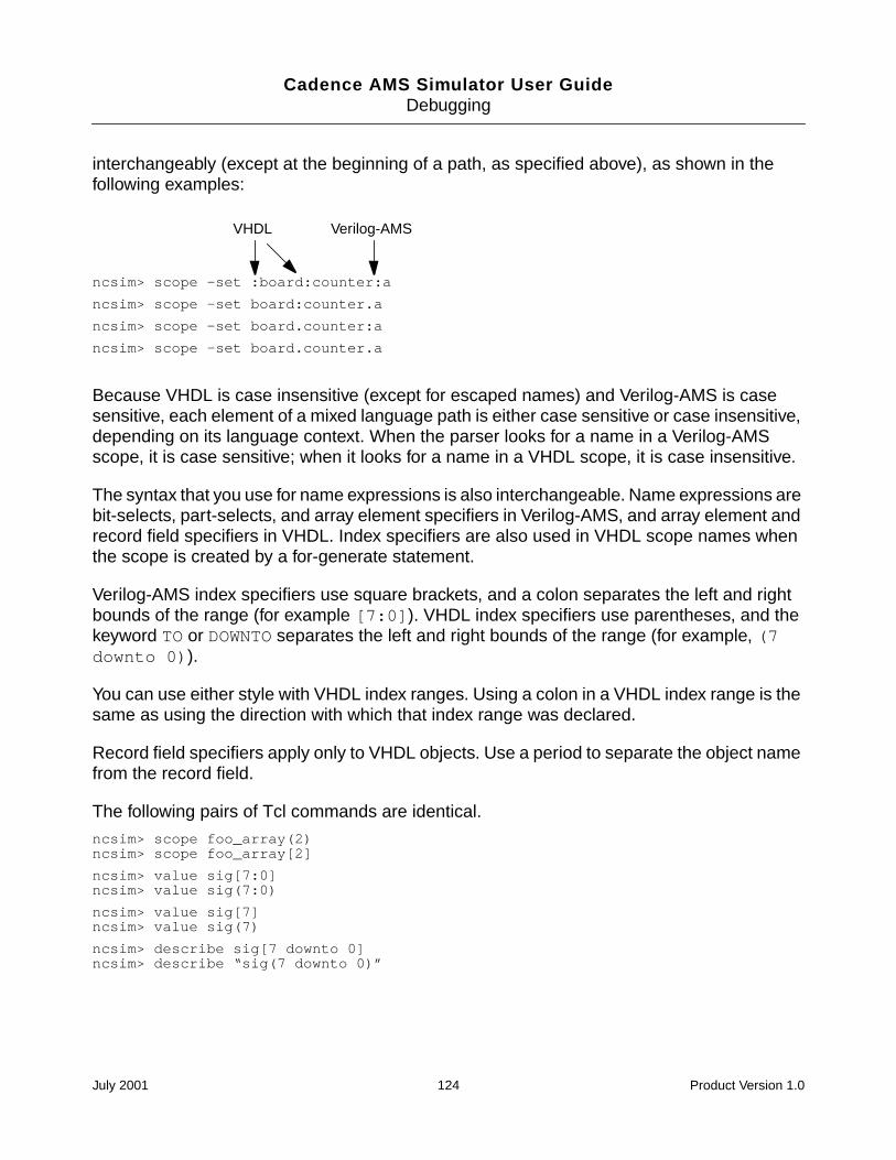
Cadence AMS Simulator User GuideDebugging
interchangeably (except at the beginning of a path, as specified above), as shown in thefollowing examples:
Because VHDL is case insensitive (except for escaped names) and Verilog-AMS is casesensitive, each element of a mixed language path is either case sensitive or case insensitive,depending on its language context. When the parser looks for a name in a Verilog-AMSscope, it is case sensitive; when it looks for a name in a VHDL scope, it is case insensitive.
The syntax that you use for name expressions is also interchangeable. Name expressions arebit-selects, part-selects, and array element specifiers in Verilog-AMS, and array element andrecord field specifiers in VHDL. Index specifiers are also used in VHDL scope names whenthe scope is created by a for-generate statement.
Verilog-AMS index specifiers use square brackets, and a colon separates the left and rightbounds of the range (for example [7:0]). VHDL index specifiers use parentheses, and thekeyword TO or DOWNTO separates the left and right bounds of the range (for example, (7downto 0)).
You can use either style with VHDL index ranges. Using a colon in a VHDL index range is thesame as using the direction with which that index range was declared.
Record field specifiers apply only to VHDL objects. Use a period to separate the object namefrom the record field.
The following pairs of Tcl commands are identical.
ncsim> scope foo_array(2)ncsim> scope foo_array[2]
ncsim> value sig[7:0]ncsim> value sig(7:0)
ncsim> value sig[7]ncsim> value sig(7)
ncsim> describe sig[7 downto 0]ncsim> describe “sig(7 downto 0)”
ncsim> scope -set :board:counter:a
ncsim> scope -set board:counter.a
ncsim> scope -set board.counter:a
ncsim> scope -set board.counter.a
Verilog-AMSVHDL
July 2001 124 Product Version 1.0
Cadence AMS Simulator User GuideDebugging
You can use either Verilog-AMS or VHDL escaped name syntax in paths. For Verilog-AMS,escaped names begin with a backslash and are terminated with white space. For example:
For VHDL, escaped names begin and end with a backslash (for example, \w3.OUT\).
The following two value commands are identical:
ncsim> value top.vending.@\w3.OUT
ncsim> value top.vending.@\w3.OUT\
Setting Breakpoints
You can interrupt the simulation by setting breakpoints.
For Verilog-AMS, you can set four kinds of breakpoints:
Condition breakpoints. See “Setting a Condition Breakpoint” on page 125.
Line breakpoints. See “Setting a Source Code Line Breakpoint” on page 126.
Object breakpoints. See “Setting an Object Breakpoint” on page 127.
Time breakpoints. See “Setting a Time Breakpoint” on page 128.
For VHDL, you can set the breakpoint types listed above plus:
Delta breakpoints. See “Setting a Delta Breakpoint” on page 128.
Process breakpoints. See “Setting a Process Breakpoint” on page 129.
Setting a Condition Breakpoint
You can stop the simulation when a specified condition is true by setting a conditionbreakpoint. This type of breakpoint is particularly useful when you want to stop the simulationat the instant when a signal has been set to an incorrect value.
A condition breakpoint triggers when any digital object referenced in the conditionalexpression changes value (wires, signals, registers, and variables) or is written to(memories) and the expression evaluates to true (nonzero). Condition breakpoints are nottriggered by changes in analog objects, but you can include analog objects in the conditional
abc.xyz.\szome_name .signal
white space
July 2001 125 Product Version 1.0
Cadence AMS Simulator User GuideDebugging
expression and their values are used when the condition is evaluated (due to a digital objectchanging value).
If you are using the Tcl command-line interface, use the stop command with the-condition option to set a condition breakpoint.
See “stop” on page 222 for details on using the stop command and for examples ofsetting breakpoints.
If you are using the SimVision analysis environment, choose Set – Breakpoint –Condition to set a condition breakpoint.
See “Setting a Condition Breakpoint” in the Affirma SimVision Analysis EnvironmentUser Guide for an example of setting a condition breakpoint using the SimControlwindow.
A condition breakpoint takes a Tcl expression as an argument. See “Tcl Expressions asArguments” on page 237 for details on the syntax of these expressions.
The simulator does not support breakpoints on individual bits of registers. If a bit-select of aregister appears in the expression, the simulator stops and evaluates the expression whenany bit of that register changes value. The same holds true for compressed wires.
For Verilog-AMS, objects included in a conditional expression must have read access. Anerror is printed if the object does not have read access. See “Enabling Read, Write, orConnectivity Access to Digital Simulation Objects” on page 94 for details on specifyingaccess to simulation objects.
See “Disabling, Enabling, Deleting, and Displaying Breakpoints” on page 129 for moreinformation on breakpoints.
Setting a Source Code Line Breakpoint
You can stop the simulation at a specified line in the source code by setting a source codeline breakpoint. This type of breakpoint is usually set when you want to simulate to a certainpoint and then single-step through lines of code.
You cannot set a line breakpoint unless you have compiled with the -linedebug option.(See the “-LINedebug” section of the “Compiling Verilog Source Files With ncvlog” chapter,in the Affirma NC Verilog Simulator Help for details on using this option.)
To set a line breakpoint:
If you are using the Tcl command-line interface, use the stop command with the -lineoption.
July 2001 126 Product Version 1.0
Cadence AMS Simulator User GuideDebugging
See “stop” on page 222 for details on using the stop command and for examples ofsetting breakpoints.
If you are using the SimVision analysis environment, choose Set – Breakpoint – Lineto set a line breakpoint.
See “Setting a Line Breakpoint” in the Affirma SimVision Analysis Environment UserGuide for an example of setting a line breakpoint using the SimControl window.
See “Disabling, Enabling, Deleting, and Displaying Breakpoints” on page 129 for moreinformation on breakpoints.
Setting an Object Breakpoint
You can stop the simulation when a specified object changes value (wires and signals) orwhen it is written to (registers, memories, variables) by setting an object breakpoint. This typeof breakpoint is usually set when you want the simulation to stop every time the signalchanges value or when you want to see the value of signals when some condition is true (forexample, on every positive edge of the clock).
To set an object breakpoint:
If you are using the Tcl command-line interface, use the stop command with the-object option.
See “stop” on page 222 for details on using the stop command and for examples ofsetting breakpoints.
If you are using the SimVision analysis environment, choose Set – Breakpoint –Object to set an object breakpoint.
See “Setting an Object Breakpoint” in the Affirma SimVision Analysis EnvironmentUser Guide for an example of setting an object breakpoint using the SimControl window.
For Verilog-AMS, the object specified as the argument must have read access for thebreakpoint to be created. See “Enabling Read, Write, or Connectivity Access to DigitalSimulation Objects” on page 94 for details on specifying access to simulation objects.
The simulator does not support breakpoints on analog objects (nets, branches, or variables).Nor does the simulator support breakpoints on individual bits of registers or variables. Forexample, the following command generates an error message.
ncsim> stop -create -object data[1]
July 2001 127 Product Version 1.0
Cadence AMS Simulator User GuideDebugging
Setting a Time Breakpoint
You can stop the simulation at a specified time by setting a time breakpoint. The time can beabsolute or relative (the default). Absolute time breakpoints are automatically deleted afterthey trigger. Relative time breakpoints are periodic, stopping, for example, every 10 ns.
This type of breakpoint is usually set when you want to advance the simulation to a certaintime point before beginning to debug or when you want to stop the simulation at regularintervals to examine signal values.
To set a time breakpoint:
If you are using the Tcl command-line interface, use the stop command with the -timeoption.
See “stop” on page 222 for details on using the stop command and for examples ofsetting breakpoints.
If you are using the SimVision analysis environment, choose Set – Breakpoint – Timeto set a time breakpoint.
See “Setting a Time Breakpoint” in the Affirma SimVision Analysis EnvironmentUser Guide for an example of setting a time breakpoint using the SimControl window.
See “Disabling, Enabling, Deleting, and Displaying Breakpoints” on page 129 for moreinformation on breakpoints.
Setting a Delta Breakpoint
For VHDL, you can stop the simulation when the simulation delta cycle count reaches aspecified delta cycle. To set a delta breakpoint:
If you are using the Tcl command-line interface, use the stop command with the-delta option.
See “stop” on page 222 for details on using the stop command and for examples ofsetting breakpoints.
If you are using the SimVision analysis environment, choose Set – Breakpoint – Deltato set a delta breakpoint.
See “Setting a Delta Breakpoint” in the Affirma SimVision Analysis EnvironmentUser Guide for an example of setting a delta breakpoint using the SimControl window.
See “Disabling, Enabling, Deleting, and Displaying Breakpoints” on page 129 for moreinformation on breakpoints.
July 2001 128 Product Version 1.0
Cadence AMS Simulator User GuideDebugging
Setting a Process Breakpoint
For VHDL, you can stop the simulation when a named process starts executing or resumesexecuting after a wait statement.
Note: You must compile with the -linedebug option to enable the setting of source line andprocess breakpoints.
To set a process breakpoint:
If you are using the Tcl command-line interface, use the stop command with the-process option.
See “stop” on page 222 for details on using the stop command and for examples ofsetting breakpoints.
If you are using the SimVision analysis environment, choose Set – Breakpoint –Process to set a process breakpoint.
See “Setting a Process Breakpoint” in the Affirma SimVision Analysis EnvironmentUser Guide for an example of setting a process breakpoint using the SimControlwindow.
See “Disabling, Enabling, Deleting, and Displaying Breakpoints” on page 129 for moreinformation on breakpoints.
Disabling, Enabling, Deleting, and DisplayingBreakpoints
After setting breakpoints, you can display information on breakpoints, disable breakpoints,enable previously disabled breakpoints, and delete breakpoints.
If you are using the command-line interface, use the stop command with the -show,-disable, -enable, or -delete modifier. The argument to these modifiers can be:
A break name or a list of break names
A pattern
The asterisk ( * ) matches any number of characters
The question mark ( ? ) matches any one character
[characters] matches any one of the characters
Any combination of literal break names and patterns
July 2001 129 Product Version 1.0
Cadence AMS Simulator User GuideDebugging
See “stop” on page 222 for details on using the stop command.
If you are using the SimVision analysis environment, choose Show – Breakpoints toopen the Debug Settings form. Click on the button next to a breakpoint to disable orenable a breakpoint. To delete a breakpoint, select the breakpoint and then click theDelete button.
See “Disabling, Enabling, Deleting, and Displaying Breakpoints” in the AffirmaSimVision Analysis Environment User Guide for an example.
Stepping Through Lines of Code
You can examine the order in which the simulator executes the statements in your model bystepping through the simulation line by line.
Note: You can always single step through the statements in the analog block of a module.However, outside the analog block, you cannot single step one line at a time or set linebreakpoints in a particular design unit unless you compiled the unit with the -linedebugoption. If you compiled the unit without this option, the run -step or run -next commandsrun the simulation until the next point where it can stop. If execution passes to a unit that wascompiled with -linedebug, full single stepping resumes.
If you are using the Tcl command-line interface:
Use run -step to simulate to the next executable line of code in any scope. Thiscommand runs one statement, stepping into subprogram calls.
Note: The -step option does not step into function calls made by an analogstatement. In this situation, the behavior of the -step option is identical to thebehavior of the -next option.
Use run -next to run one statement, stepping over any subprogram calls.
See “run” on page 202 for details on using the run command.
If you are using the SimVision analysis environment, choose Control – Step orControl – Next.
You can also click on the Single Step or Step Over buttons on the Tool Bar.
See “Stepping Through the Simulation” in the Affirma SimVision AnalysisEnvironment User Guide for an example.
July 2001 130 Product Version 1.0
Cadence AMS Simulator User GuideDebugging
Forcing and Releasing Signal Values
You can ask “What if” questions about your model by interactively forcing objects to desiredvalues and seeing if the patch fixes the problem. If it does, you can then edit your source fileto incorporate the change.
Note: You cannot use the force command on an analog object. In addition, you cannot usethe force command on digital objects while the analog solver is active.
The object that is being forced must have write access. To specify write access, use the-access or -afile option when you elaborate the design with ncelab. See “EnablingRead, Write, or Connectivity Access to Digital Simulation Objects” on page 94 for details onspecifying access to simulation objects.
If you are using the Tcl command-line interface, use the force command to set aspecified object to a given value and force it to retain that value until it is released with arelease command or until another force is placed on it.
See “force” on page 183 and “release” on page 196 for details on using thesecommands.
If you are using the SimVision analysis environment, choose Set – Force to force asignal to a given value. To release a signal, position the pointer over the signal, click theright mouse button, and select Release Force to release the signal. This choice isgrayed out while the analog solver is active because you cannot use the forcecommand in that circumstance.
See “Forcing and Releasing Signal Values” in the Affirma SimVision AnalysisEnvironment User Guide for an example.
Depositing Values to Signals
Besides forcing an object to a desired value using the force command (Set — Force inSimVision), another way to ask “What if” questions about your model as you debug is tointeractively deposit a value to a specified object.
When you deposit a value to an object, behaviors that are sensitive to value changes on theobject run when the simulation resumes, just as if the value change was caused by theVerilog-AMS or VHDL code.
You can deposit a value to an object immediately, at a specified time in the future, or after aspecified delay. You can also specify that you want to deposit the value after an inertial delayor after a transport delay. A deposit without a delay is similar to a force in that the specified
July 2001 131 Product Version 1.0
Cadence AMS Simulator User GuideDebugging
value takes effect and propagates immediately. However, it differs from a force in that futuretransactions on the signal are not blocked.
For VHDL, you can deposit to ports, signals, and variables if no delay is specified. If a delayis specified, you cannot deposit to variables or to signals with multiple sources.
For Verilog-AMS, you can deposit to ports, signals (wires and registers), and variables.
For Verilog-AMS, the object that you want to deposit a value to must have write access. Anerror is printed if it does not. To specify write access, use the -access or -afile optionwhen you elaborate the design with ncelab. See “Enabling Read, Write, or ConnectivityAccess to Digital Simulation Objects” on page 94 for details on specifying access tosimulation objects.
Note: You cannot use the deposit command on an analog object. In addition, you cannotuse the deposit command on digital objects while the analog solver is active.
To deposit a value to an object:
If you are using the Tcl command-line interface, use the deposit command to set aspecified object to a given value.
See “deposit” on page 168 for details on using the deposit command.
If you are using the SimVision analysis environment, choose Set – Deposit to deposita value to a signal.
See “Depositing Values to Signals” in the Affirma SimVision Analysis EnvironmentUser Guide for an example.
Displaying Information About Simulation Objects
You can display information about a simulation object, including its declaration.
If you are using the Tcl command-line interface, use the describe command.
See “describe” on page 171 for details on using this command.
If you are using the SimVision analysis environment,
Choose Show – Description and fill in the Show Description form with the nameof the object.
Place the cursor over the object for which you want information. In particular, notethat you can place your cursor over the parenthesis following an access function todisplay information about unnamed branches. For example, you can display the
July 2001 132 Product Version 1.0
Cadence AMS Simulator User GuideDebugging
branch potential and flow (if the flow is available) of the unnamed branch between aand b by placing your cursor over either of the left parentheses in the statement:V(a,b) <+ r *I(a,b)
See “Displaying Information About Simulation Objects” in the Affirma SimVisionAnalysis Environment User Guide for an example using SimControl.
Displaying the Drivers of Signals
You can display a list of all of the contributors to the value of a specified digital object.
Note: You cannot list drivers for analog variables, analog nets, or branches.
If you are using the Tcl command-line interface, use the drivers command. Forexample:
ncsim> drivers board.count
See “drivers” on page 174 for details on using this command and for examples of thereport format for Verilog-AMS signals and for VHDL signals.
You can use the scope -drivers [scope_name] command to display the drivers ofeach object that is declared within a specified scope. You can use the scope-describe [scope_name] command to give the description of each object that isdeclared within the specified scope. See “scope” on page 212 for details.
If you are using the SimVision analysis environment, choose Show – Drivers and fill inthe Show Drivers form with the name of the signal(s) for which you want to display driverinformation.
See “Displaying Signal Drivers” in the Affirma SimVision Analysis Environment UserGuide for an example.
For Verilog-AMS, the drivers command cannot find the drivers of a wire or register unlessthe object has connectivity access. However, even if you have specified access to the object,its drivers may have been collapsed, combined, or optimized away. In this case, the output ofthe drivers (or Show – Drivers) command might indicate that the object has no drivers.See “Enabling Read, Write, or Connectivity Access to Digital Simulation Objects” on page 94for details on specifying access to simulation objects.
July 2001 133 Product Version 1.0
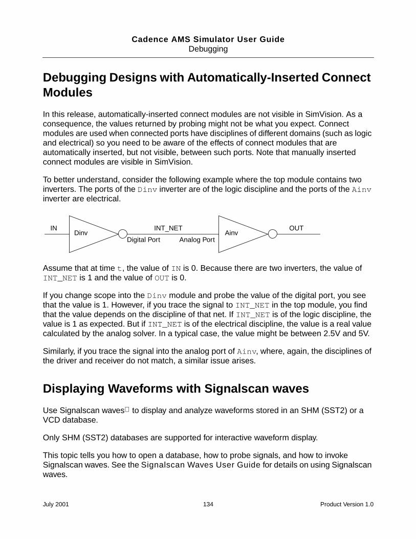
Cadence AMS Simulator User GuideDebugging
Debugging Designs with Automatically-Inserted ConnectModules
In this release, automatically-inserted connect modules are not visible in SimVision. As aconsequence, the values returned by probing might not be what you expect. Connectmodules are used when connected ports have disciplines of different domains (such as logicand electrical) so you need to be aware of the effects of connect modules that areautomatically inserted, but not visible, between such ports. Note that manually insertedconnect modules are visible in SimVision.
To better understand, consider the following example where the top module contains twoinverters. The ports of the Dinv inverter are of the logic discipline and the ports of the Ainvinverter are electrical.
Assume that at time t, the value of IN is 0. Because there are two inverters, the value ofINT_NET is 1 and the value of OUT is 0.
If you change scope into the Dinv module and probe the value of the digital port, you seethat the value is 1. However, if you trace the signal to INT_NET in the top module, you findthat the value depends on the discipline of that net. If INT_NET is of the logic discipline, thevalue is 1 as expected. But if INT_NET is of the electrical discipline, the value is a real valuecalculated by the analog solver. In a typical case, the value might be between 2.5V and 5V.
Similarly, if you trace the signal into the analog port of Ainv, where, again, the disciplines ofthe driver and receiver do not match, a similar issue arises.
Displaying Waveforms with Signalscan waves
Use Signalscan waves to display and analyze waveforms stored in an SHM (SST2) or aVCD database.
Only SHM (SST2) databases are supported for interactive waveform display.
This topic tells you how to open a database, how to probe signals, and how to invokeSignalscan waves. See the Signalscan Waves User Guide for details on using Signalscanwaves.
IN OUTDinv Ainv
Digital Port Analog Port
INT_NET
July 2001 134 Product Version 1.0
Cadence AMS Simulator User GuideDebugging
Note: The objects that you want to probe to an SHM or VCD database must have readaccess. By default, Verilog-AMS objects in the design are not given read access. Use the-access +r option or the -afile access_file option when you elaborate the design(+ncaccess+r or +ncafile+access_file if you are running ncverilog) to provide readaccess.
Creating a Database and Probing Signals
You can open a database, probe digital signals, and save the results in the database byentering Tcl commands at the prompt or by using the graphical user interface. To probeanalog signals, however, you use the save statement in the analog simulation control file. Forinformation, see “save” on page 104.
See “Managing Databases” on page 117 for details on opening a database. That topic alsocontains information on displaying information about databases and on disabling, enabling,and closing a database.
See “Setting and Deleting Probes” on page 119 for details on probing digital signals. See“save” on page 104 for details on probing analog signals.
You also can use a set of system tasks from the digital context to open an SHM database,probe signals, and save the results in the waveform database. You must enter the systemtasks into the Verilog-AMS description prior to simulation.The system tasks are:
Example:
initialbegin
$shm_open("waves.shm");$shm_probe();#1 $stop; // stop simulation at time 1
end
System task Description
$shm_open(); Opens a simulation database.
$shm_probe(); Selects signals whose simulation value changes willenter the simulation database.
$shm_close; Closes a simulation database.
July 2001 135 Product Version 1.0
Cadence AMS Simulator User GuideDebugging
Opening a Database with $shm_open
Use the $shm_open system task from a digital context to open an SHM database.
Syntax:
$shm_open ( [ argument , argument... ] ) ;
The arguments, all optional, are:
"db_name" specifies the filename of the simulation database. If you do notspecify the database name, a database called waves.shm isopened in the current directory.
is_sequence_time dumps all value changes to the database.
By default, when probing to an SHM database, the simulatordiscards multiple value changes for an object during onesimulation time and dumps only the final value at the end of thatsimulation time. Specify 1 for the is_sequence_timeargument if you want to dump all value changes to the SHMdatabase. You can then use Signalscan waves to expand asingle moment of simulation time to show the sequence of valuechanges that occurred at that time. For example,
$shm_open("mywaves.shm", 1, , );
db_size specifies the maximum size (in bytes) of the transition file (.trnfile).
The simulator maintains the size limit by discarding the earliestrecorded values as new values are dumped, such that thedatabase always contains the most recent values for eachprobed object.
When the size limit is exceeded, the waveform window displaysan "unknown" value for each object from the beginning of thesimulation to the time of the first non-discarded value.
The SHM database uses about 2.5Mb of disk space, even if youspecify a lower limit. However, the database size will not exceedthe limit if the limit is greater than 2.5Mb. For example,
$shm_open("mywaves.shm", 1, 250000,);
July 2001 136 Product Version 1.0
Cadence AMS Simulator User GuideDebugging
is_compression compresses the SHM database to reduce its size. The defaultsetting is 0. Specify 1 to compress the database file. Forexample,
$shm_open("mywaves.shm", 1, , 1);
Probing Signals with $shm_probe
The syntax for the $shm_probe system task, which must be used from a digital context, isas follows:
$shm_probe(scope0, node0, scope1, node1, ...);
Each scope refers to a scope in the hierarchy, and each node refers to a node specifier.
If a scope parameter is omitted, the default is the current scope. If a node parameter isomitted, the default is all inputs, outputs, and inouts of the specified scope.
The word node, as used here, refers to nodes in a hierarchical structure; it has nothing to dowith the word as it is used in analog simulation. A node specifier can be one of the following:
Examples of node specifiers:
$shm_probe("A");
Specifies all the nodes in the current scope.
$shm_probe(alu, adder);
Node Specifier Signals That Enter the Database
"A" All nodes (including inputs, outputs and inouts) of the specifiedscope.
"S" Inputs, outputs, and inouts of the specified scope, and in allinstantiations below it, except inside library cells.
"C" Inputs, outputs, and inouts of the specified scope, and in allinstantiations below it, including inside library cells.
"AS" All nodes (including inputs, outputs and inouts) of the specifiedscope, and in all instantiations below it, except inside library cells.
"AC" All nodes (including inputs, outputs and inouts) in the specifiedscope and in all instantiations below it, even inside library cells.
July 2001 137 Product Version 1.0
Cadence AMS Simulator User GuideDebugging
Specifies all the inputs, outputs, and inouts in the modules alu and adder.
$shm_probe("S", top.alu, "AC");
Specifies all the inputs, outputs, and inouts in the current scope, and below, excludingthose in library cells. All the nodes in the top.alu module and below, including those inlibrary cells.
Invoking Signalscan waves
When working with waveforms, there are two basic use models:
Simulate and generate a database. Then invoke the waveform tool to view thewaveforms.
Invoke the waveform viewer and then simulate so that you can view the waveforms asthe simulation progresses.
Invoking Signalscan waves to View a Post-Simulation Database
After the database has been created, you can view the waveforms with Signalscan waves.Invoke Signalscan waves with the following command:
% signalscan [database_name]
For example:
% signalscan
% signalscan waves.shm
If you do not specify a database on the command line:
1. Choose File – Open Simulation File to open the file browser.
2. In the Directories list box, double click on the directory you want.
3. Select the .trn file in the File list box.
4. Click OK.
5. On the waveform window, choose Windows – Design Browser or click DesBrows toopen the Design Browser.
6. Select the signals you want to display in the waveform window.
7. Click AddToWave to add the signals to the waveform window.
If you specify a database on the command line:
July 2001 138 Product Version 1.0
Cadence AMS Simulator User GuideDebugging
1. Choose Windows – Design Browser or click DesBrows to open the Design Browser.
2. Select the signals you want to display in the waveform window and click AddToWave.
Invoking Signalscan waves for Interactive Waveform Display
If you want to interactively debug using the waveform tool:
1. (Optional) Open a database with the File – SHM Database – Open command from themenu in the Cadence AMS Simulator window.
On the Open Database form, select the open as default database option and set otheroptions, then click OK or Apply.
If you do not open a digital database, one is opened for you by default.
2. Probe signals or scopes and invoke Signalscan waves.
Select the signals or scopes you want to probe and then choose Tools – Waveformfrom the menu in the Cadence AMS Simulator window. You can also click the WaveformView button or select Wave Trace from the popup menu.
This probes the selected signals or scopes to the default database and then invokesSignalscan waves. The selected signals are displayed in the waveform window.
Analog signals can be probed to the waveform window only if an analog database hasbeen opened by the analog simulation control file. In this case, you can select any signaland display the waveform by clicking Waveform View.
3. Simulate.
If you don’t preselect objects, choosing Tools – Waveform or clicking the Waveform Viewbutton invokes Signalscan waves. You can then probe signals and add them to the waveformwindow using the Design Browser.
A useful shortcut is to preselect the signals you will want to view in the waveform tool and thenchoose Tools – Waveform (or click the Waveform View button or select Wave Trace fromthe popup menu). This opens a default database called waves.shm, probes the selectedsignals, and invokes Signalscan waves with the selected signals displayed in the waveformwindow. If you use this shortcut, however, the Open Database form does not appear, and youcannot select options that appear on that form, such as the option to record all events or theoption to specify a maximum database size.
July 2001 139 Product Version 1.0
Cadence AMS Simulator User GuideDebugging
Comparing Databases with Comparescan
Use Comparescan to compare simulation histories of digital objects stored in SHM (SST2) orVCD databases. Comparescan is not supported for analog objects.
Comparescan is a comprehensive comparison tool that can compare single signals orcomplete simulations. Using these comparisons, you can verify that different simulation runsproduce functionally equivalent results.
You can use Comparescan to compare simulations performed:
At the same or at different levels (RTL to RTL, gate to gate, RTL to gate, behavioral togate, and so on).
After design optimizations (for speed or area).
After technology changes (shrink or vendor).
Using different clock rates.
For regression testing.
For test vector applications, you can use Comparescan to perform comparisons:
Of best and worst case timing simulations.
Of simulations before and after backannotation.
After clock tree insertions.
You can also use Comparescan to compare simulations performed on different simulators.For example, you can compare simulation results from Verilog-XL and results from theCadence AMS simulator.
You cannot compare a VCD database with an SHM database.
See the Comparescan User Guide for details on using Comparescan.
Displaying Debug Settings
While debugging, you may open databases, set probes, set breakpoints, set aliases, and soon. To display your current debug settings:
If you are using the Tcl command-line interface, use the appropriate modifier to displayinformation. For most commands, this is the -show modifier. For example:
ncsim> database -show
July 2001 140 Product Version 1.0
Cadence AMS Simulator User GuideDebugging
ncsim> probe -show
Use the alias command without a modifier to display information about aliases youhave set, as shown in the following example:
ncsim> alias
e exit
f2 finish 2
h history
ncsim>
If you are using the SimVision analysis environment, use the commands on the Showmenu. For example, to view information on the breakpoints you have set, chooseShow – Breakpoints.
See “Displaying Debug Settings” in the Affirma SimVision Analysis EnvironmentUser Guide for an example.
Setting a Default Radix
If you are using the SimVision analysis environment, choose Options – Default Radix toselect a default radix for the simulator to use in displaying digital signal and analog variablevalues. Analog nets and branches are not affected by this option.
The radix you choose is used to display values when you:
Double click on an object in the Source Browser.
Position your cursor over an object in the Source Browser.
Right click on an object in the Source Browser and select Show Value from the pop up.
Click on the Show Value icon ( ) in the SimControl tool bar.
Open a new Watch Window.
Choose Set – Force to open the Set Force form.
The Show Value form has its own buttons so that you can override the default radix forparticular operations.
Setting the Format for Branches
If you are using the SimVision analysis environment, choose Options – Branches to selectthe format for the simulator to use in displaying analog branch values.
July 2001 141 Product Version 1.0
Cadence AMS Simulator User GuideDebugging
The format you choose is used to display values when you:
Position your cursor over an object in the Source Browser.
Open a new Watch Window. However, you can then choose a different format for thewatch window by choosing, from the Watch Window menu, Options – Branches.
In the Navigator, the format of branches is determined by the choices in the Navigator ObjectList Options dialog (opened by choosing Options – Object List), not by the choices madefrom the menu in the Cadence AMS Simulator window.
Setting the Format for Potential and Flow
If you are using the SimVision analysis environment, choose Options – Potential/FlowFormatting to select the format for the simulator to use in displaying potentials and flows.
The format you choose is used to display values when you:
Position your cursor over an object in the Source Browser.
Open a new Watch Window. However, you can then choose a different format for thewatch window by choosing, from the Watch Window menu, Options – Potential/FlowFormatting.
In the Navigator, the potential/flow formatting is determined by the choices in the NavigatorObject List Options dialog (opened by choosing Options – Object List), not by the choicesmade from the menu in the Cadence AMS Simulator window.
Setting Variables
You can set Tcl variables to help you debug your design. In addition to user-defined variables,the simulator includes several predefined Tcl variables that you can use to control varioussimulator features.
You can:
Set a variable or change the value of a variable with the built-in Tcl set command.
ncsim> set abc 10
ncsim> set vlog_format %b
Delete a variable, with the unset command.
ncsim> unset abc
July 2001 142 Product Version 1.0
Cadence AMS Simulator User GuideDebugging
Display a list of predefined simulation variables and their current values, with the help-variables command.
ncsim> help -variables
Display a list of all currently set variables, with the info vars command. Thiscommand does not display variable values.
ncsim> info vars
You can put variable definitions in an input file and then execute the commands in this file byusing the -input option when you invoke the simulator. You can also execute thesecommands by using the source command or the File – Commands – Source menucommand after invoking the simulator.
See “Setting Variables” in the Affirma SimVision Analysis Environment User Guide foran example of using SimControl to set a Tcl variable, display a list of variables that have beenset, change the value of a predefined variable, and unset a variable.
The predefined Tcl variables are:
assert_1164_warnings = value
Controls the display of warnings from builtin functions from the std_logic_1164 package. Thevalue can be yes or no. If you set it to no, the simulator suppresses the warnings. Thisvariable is initially set to yes.
assert_report_level = value
Sets the minimum severity level for which VHDL assertion report messages should be output.The value can be note, warning, error, failure, or never.
If the severity level specified in the assertion statement is at or above the severity levelspecified by this variable, the report message is written to standard output, along with thetime, severity, and the name of the design unit in which the assertion occurred.
This variable is initially set to note.
assert_stop_level = value
Specifies the minimum severity level for which VHDL assertions cause the simulation to stop.
The value can be note, warning, error, failure, or never.
July 2001 143 Product Version 1.0
Cadence AMS Simulator User GuideDebugging
If the severity level specified in the assertion statement is at or above the severity levelspecified by this variable, the simulation stops. If the simulator is in interactive mode, it returnsthe Tcl prompt. If not in interactive mode, the simulator exits.
This variable is initially set to error.
autoscope = value
The value of this variable can be yes or no.
yes—Set the debug scope to the scope of the current execution point (if any) when thesimulator stops.
no—Do not automatically set the debug scope to the scope of the current execution point(if any) when the simulator stops.
This variable is initially set to yes.
clean = value
The value of this variable can alternate between 1 and 0 as the simulation runs:
1—The simulation is in a clean state, and you can use the save -simulationcommand to create a snapshot of the current simulation state.
Note: You cannot, however, save a snapshot when the design contains any analog.
0—The simulation is not in a clean state. If you want to save the simulation state, use therun -clean command to run the simulation to the next point at which the savecommand will work.
Note: The run -clean command is disabled when the design has any analog content.
display_unit = value
The value of this variable is the time unit used to display time values throughout the userinterface.
auto—Use the largest time unit in which the time can be expressed as an integer.
module—Use the timescale of the module that is the current debug scope.
FS, 10FS, 100FS, ...
July 2001 144 Product Version 1.0
Cadence AMS Simulator User GuideDebugging
xlstyle—Print time values using the same formatting rules that Verilog-XL uses. XLfollows any $timeformat that is in effect, and, if there is none, formats time values tothe smallest `timescale precision. Setting display_unit to xlstyle can make iteasier to compare simulation results from the two simulators.
Setting the value to xlstyle affects the formatting of time values only. It does not affectthe format of messages.
The default value is auto unless you have invoked the simulator (ncsim) with the-xlstyle_units command-line option, in which case the default value is xlstyle.
snapshot = value
The value of this variable is the name of the currently loaded simulation snapshot. Thisvariable is read-only.
tcl_prompt1 = value
The value of this variable is the command that generates the main Tcl prompt. The defaultis:
puts -nonewline “ncsim> “
The following command changes the prompt to ncverilog>:
ncsim> set tcl_prompt1 puts -nonewline “ncverilog> “
tcl_prompt2 = value
The value of this variable is the command that generates the prompt you get if you pressthe Return key before completing a Tcl command. The default is:
puts -nonewline “> “
The following command changes the prompt to Give me more>:
ncsim> set tcl_prompt2 puts -nonewline “Give me more> “
time_unit = value
The value of this variable is the unit to be used in time or cycle specifications that do notcontain an explicit unit. The value can be: FS, 10FS, 100FS, ... , SEC, MIN, HR, CYCLE, ormodule. For example, if time_unit = NS, the following command runs the simulation for100 ns.
ncsim> run 100
July 2001 145 Product Version 1.0
Cadence AMS Simulator User GuideDebugging
This variable is initially set to module, which uses the timescale of the module that is thecurrent debug scope.
time_scale = value
The value of this variable is the timescale of the current debug scope. This variable isread-only.
vhdl_format = value
The value of this variable is the format for the output of VHDL values in describe output,stop point messages, and expression results. The value can be set to %h, %x, %d, %o, or %b,or %v.
This variable is initially set to %v.
vlog_format = value
The value of this variable is the format for the output of Verilog-AMS values in describeoutput, stop point messages, and expression results. The value can be set to %h, %x, %d, %o,or %b.
This variable is initially set to %h.
Editing a Source File
If you are using the Cadence SimVision analysis environment, you can open a source file forediting in your editor from the SimControl window. To specify an editor, choose Options –Preferences. On the Preferences form, specify the editor in the “Editing” section of this form.See “Editing” in the Affirma SimVision Analysis Environment User Guide for anexample.
You can invoke your editor in two ways:
Click on the Edit Source button ( ) in the SimControl tool bar.
This invokes your editor on the file currently displayed in the Source Browser. The cursoris at the first line visible in the Source Browser.
Choose File – Edit Source.
July 2001 146 Product Version 1.0
Cadence AMS Simulator User GuideDebugging
The Edit File form appears. Use this form to specify the filename and the line number tobring up in the editor.
In the Filename field, enter the name of the file you want to edit.
In the Line Number field, enter the line number you want to edit.
Click OK or Apply to invoke your editor.
See “Editing a Source File” in the Affirma SimVision Analysis Environment User Guidefor an example.
Searching for a Line Number in the Source Code
If you are using the SimVision analysis environment, the File – Find – Line command letsyou quickly find a line of text in the source code displayed in the Source Browser.
See “Searching for a Line Number in the Source Code” in the Affirma SimVision AnalysisEnvironment User Guide for an example.
Searching for a Text String in the Source Code
If you are using the SimVision analysis environment, the File – Find – Text command letsyou quickly locate a text string in the source code displayed in the Source Browser.
See “Searching for Text in the Source Code” in the Affirma SimVision AnalysisEnvironment User Guide for an example.
Configuring Your Simulation Environment
When you use the Cadence SimVision analysis environment, you can configure yoursimulation environment to reflect your preferences. To set your preferences, chooseOptions – Preferences. This command lets you:
Define the behavior of warning pop-ups.
Control the behavior of the Source Browser.
Specify a text editor.
Select the size of the display fonts.
July 2001 147 Product Version 1.0
Cadence AMS Simulator User GuideDebugging
See “Configuring Your Simulation Environment” in the Affirma SimVision AnalysisEnvironment User Guide for an example of using the Preferences form.
Saving and Restoring Your Simulation Environment
You can save the current state of the debug environment at any time.
If you are using the Tcl command-line interface, use the save -environmentcommand.
ncsim> save -environment [filename]
This command generates a script containing Tcl commands to recreate breakpoints,databases, probes, and the values of Tcl variables. The filename argument isoptional. If not specified, the script is written to standard output.
See “save” on page 206 for more information on the save -environment commandand for an example.
To restore the environment, execute the script with the Tcl source command or use the-input option when you invoke the simulator.
If you are using the SimVision analysis environment, choose File – Setup – Save tocreate the script. Choose File – Setup – Restore to restore your debug settings.
See “Saving and Restoring Your Debug Environment” in the Affirma SimVisionAnalysis Environment User Guide for an example.
When you source a script containing Tcl commands to restore a saved debug environmentor use the File – Setup – Restore command, the debug settings in the script are mergedwith your current debug settings.
Note: These scripts are meant to be sourced into a “clean” environment. That is, typically yousource the script (or use File – Setup – Restore) after you have invoked the simulator, butbefore you set any breakpoints or probes or open a database.
If you invoke the simulator, set some breakpoints and probes, and then source a script thatcontains commands to set breakpoints and probes, the simulator will probably generateerrors telling you that some commands in the script could not be executed. These errors aredue to name conflicts. For example, you may have set a breakpoint that received the defaultname “1”, and the command in the script is trying to create a breakpoint with the same name.You can, of course, give your breakpoints unique names to avoid this problem. You can alsoedit the scripts to make them work the way you would like them to work.
July 2001 148 Product Version 1.0
Cadence AMS Simulator User GuideDebugging
Creating or Deleting an Alias
You can create your own shorthand for a command or series of commands by setting an alias.
If you are using the Tcl command-line interface, use the alias command to create anew alias.
See the “alias” section of the “Using the Tcl Command-Line Interface” chapter, in theAffirma NC Verilog Simulator Help for details on using the alias command and foran example.
If you are using the SimVision analysis environment, choose Set – Alias and fill in theSet Alias form with the name and definition of the alias.
To display the aliases that are currently set, choose Show – Aliases.
See “Creating or Deleting an Alias” in the Affirma SimVision Analysis EnvironmentUser Guide for an example.
You cannot create an alias with the same name as a predefined Tcl command. For example,
ncsim> alias gets value
ncsim: *E,ALNORP: cannot create an alias for Tcl command gets.
Getting a History of Commands
You can get a listing of all the commands you have entered by using the built-in Tcl historycommand. The history command lets you re-execute commands without retyping them.You also can use the history command to modify old commands—for example, to fixtypographical errors.
If you are using the Tcl command-line interface, enter the history command at thencsim> prompt.
See the “history” section of the “Using the Tcl Command-Line Interface” chapter, in theAffirma NC Verilog Simulator Help for details on the history command and for anexample.
If you are using the SimVision analysis environment, choose Show – History. The listof commands is displayed in the I/O region of the window.
See “Getting a History of Commands” in the Affirma SimVision AnalysisEnvironment User Guide for an example.
July 2001 149 Product Version 1.0
Cadence AMS Simulator User GuideDebugging
Managing Custom Buttons
If you are using the Cadence SimVision analysis environment, you can create custom buttonsfor commands and add them to the Tool Bar. You can assign one or multiple Tcl commandsto a custom button. Customized buttons can automate your debugging tasks by letting youexecute a series of Tcl commands with one mouse click. You save time by avoiding having toselect individual Tcl commands for performing frequent tasks.
You can:
Create buttons that perform a specified function.
Edit the buttons to change the functions they perform.
Reorder the buttons on the Tool Bar.
Export the buttons to save them in a file.
Import a file of user-defined buttons.
See “Managing Custom Buttons” in the Affirma SimVision Analysis Environment UserGuide for details and examples.
July 2001 150 Product Version 1.0
Cadence AMS Simulator User Guide
11Time-Saving Techniques for the AnalogSolver
In this chapter, you learn about different methods to reduce the time devoted to simulating theanalog sections of a design. The topics discussed are:
Adjusting Speed and Accuracy on page 152
Saving Time by Selecting a Continuation Method on page 152
Specifying Efficient Starting Points on page 152
July 2001 151 Product Version 1.0
Cadence AMS Simulator User GuideTime-Saving Techniques for the Analog Solver
Adjusting Speed and Accuracy
You can use the errpreset parameter to increase the speed of transient analyses, but thisspeed increase requires some sacrifice of accuracy. The greatest speedup comes from usingerrpreset=liberal. Greater accuracy, but lower speed, can be obtained by usingerrpreset=moderate, or errpreset=liberal.
Saving Time by Selecting a Continuation Method
The Cadence AMS simulator analog solver normally starts with an initial estimate and thentries to find the solution for an analog circuit using the Newton-Raphson method. If thisattempt fails, the simulator automatically tries several continuation methods to find a solutionand tells you which method was successful. Continuation methods modify the circuit so thatthe solution is easy to compute and then gradually change the circuit back to its original form.Continuation methods are robust, but they are slower than the Newton-Raphson method.
If you need to modify and resimulate a circuit that was solved with a continuation method, youprobably want to save simulation time by directly selecting the continuation method you knowwas previously successful.
You select the continuation method with the homotopy parameter of the set or optionsstatements. In addition to the default setting, all, five settings are possible for thisparameter: gmin stepping (gmin), source stepping (source), the pseudotransient method(ptran), and the damped pseudotransient method (dptran). You can also prevent the useof continuation methods by setting the homotopy parameter to none.
Specifying Efficient Starting Points
The Cadence AMS simulator’s analog solver arrives at a solution for a simulation bycalculating successively more accurate estimates of the final result. You can increasesimulation speed by providing information that the simulator uses to increase the accuracy ofthe initial solution estimate. To provide a good starting point for a simulation:
Specify initial conditions for components and nodes.
Specify solution estimates with nodesets.
July 2001 152 Product Version 1.0
Cadence AMS Simulator User GuideTime-Saving Techniques for the Analog Solver
Saving Time by Specifying State Information
The Cadence AMS simulator lets you provide state information (the current or last-knownstatus or condition of a process, transaction, or setting) to the transient analysis. You canspecify two kinds of state information:
Initial conditions
The ic statement lets you specify voltages on nodes for the starting point of a transientanalysis. In the Verilog-AMS source, you can specify voltages on capacitors and currentson inductors.
Nodesets
Nodesets are estimates of the solution you provide for the transient analysis. Unlike initialconditions, nodeset values have no effect on the final results. Nodesets usually act onlyas aids in speeding convergence, but if a circuit has more than one solution, as with alatch, nodesets can bias the solution to the one closest to the nodeset values.
Setting Initial Conditions for the Transient Analysis
You can specify initial conditions that apply to the transient analysis. The ic statement andthe ic parameter described in this section set initial conditions for the transient analysis inthe netlist. In general, you use the ic parameter of individual components to specify initialconditions for those components, and you use the ic statement to specify initial conditionsfor nodes. You can specify initial conditions for inductors with either method.
Note: Do not confuse the ic parameter for individual components with the ic parameter ofthe transient analysis. The latter lets you select from among different initial conditionsspecifications for a given transient analysis.
Specifying Initial Conditions for Components
You can specify initial conditions in the instance statements of capacitors, inductors, andwindings for magnetic cores. The ic parameter specifies initial voltage values for capacitorsand current values for inductors and windings. In the following Verilog-AMS example, theinitial condition voltage on the capacitor is set to two volts:
capacitor #(.c(1u),.ic(2)) c1 (net1,net2) ;
Specifying Initial Conditions for Nodes
You use the ic statement in the analog simulation control file to specify initial conditions fornodes or initial currents for inductors. The nodes can be inside a subcircuit or internal nodesto a component.
July 2001 153 Product Version 1.0
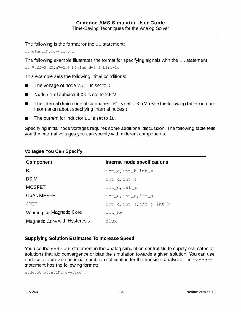
Cadence AMS Simulator User GuideTime-Saving Techniques for the Analog Solver
The following is the format for the ic statement:
ic signalName=value …
The following example illustrates the format for specifying signals with the ic statement.
ic Voff=0 X3.n7=2.5 M1:int_d=3.5 L1:1=1u
This example sets the following initial conditions:
The voltage of node Voff is set to 0.
Node n7 of subcircuit X3 is set to 2.5 V.
The internal drain node of component M1 is set to 3.5 V. (See the following table for moreinformation about specifying internal nodes.)
The current for inductor L1 is set to 1u.
Specifying initial node voltages requires some additional discussion. The following table tellsyou the internal voltages you can specify with different components.
Supplying Solution Estimates To Increase Speed
You use the nodeset statement in the analog simulation control file to supply estimates ofsolutions that aid convergence or bias the simulation towards a given solution. You can usenodesets to provide an initial condition calculation for the transient analysis. The nodesetstatement has the following format:
nodeset signalName=value …
Voltages You Can Specify
Component Internal node specifications
BJT int_c, int_b, int_e
BSIM int_d, int_s
MOSFET int_d, int_s
GaAs MESFET int_d, int_s, int_g
JFET int_d, int_s, int_g, int_b
Winding for Magnetic Core int_Rw
Magnetic Core with Hysteresis flux
July 2001 154 Product Version 1.0
Cadence AMS Simulator User GuideTime-Saving Techniques for the Analog Solver
Values you can supply with the nodeset statement include voltages on topological nodes,including internal nodes, and currents through voltage sources, inductors, switches,transformers, N-ports, and transmission lines.
The following example illustrates the format for specifying signals with the nodesetstatement.
nodeset Voff=0 X3.n7=2.5 M1:int_d=3.5 L1:1=1u
This example sets the following solution estimates:
The voltage of node Voff is set to 0.
Node n7 of subcircuit X3 is set to 2.5 V.
The internal drain node of component M1 is set to 3.5 V. (See “Voltages You Can Specify”on page 154, for more information about specifying internal nodes.)
The current for inductor L1 is set to 1u.
Specifying State Information for Individual Analyses
You can specify state information for individual analyses in two ways:
You can use the ic parameter of the transient analysis to choose which previousspecifications are used.
You can create a state file that is read by an individual analysis.
Choosing Which Initial Conditions Specifications Are Used for a Transient Analysis
The ic parameter in the transient analysis lets you select among several options for whichinitial conditions to use. You can choose the following settings:
Initial Condition Settings for the ic Parameter
Parameter setting Action taken
node The ic statements are used, and the ic parameter settings on thecapacitors and inductors are ignored.
dev The ic parameter settings on the capacitors and inductors areused, and the ic statements are ignored.
all Both the ic statements and the ic parameters are used. Ifspecifications conflict, ic parameters override ic statements.
July 2001 155 Product Version 1.0
Cadence AMS Simulator User GuideTime-Saving Techniques for the Analog Solver
Specifying State Information with State Files
You can also specify initial conditions and estimate solutions by creating a state file that isread by the transient analysis. You can create a state file in two ways:
You can instruct the simulator to create a state file in the transient analysis for future use.
You can create a state file manually in a text editor.
Telling the AMS Simulator to Create a State File
You can instruct the simulator to write a state file from the initial point in an analysis, by usingthe write parameter. The following example writes a state file named ua741.tran.
timeDom tran stop=1u readns="ua741.tran" write="ua741.tran"
Creating a State File Manually
The syntax for creating a state file in a text editor is simple. Each line contains a signal nameand a signal value. Anything after a pound sign (#) is ignored as a comment. The following isan example of a simple state file:
# State file generated from circuit file 'wilson'# during 'stepresponse' at 5:39:38 PM, jan 21, 2000.
1 .5887935106125342 1.174062479892723 14.9900516233357pwr 15vcc:p -9.9483766642647e-06
Reading State Files
To read a state file as a nodeset, use the readns parameter. This example reads the filesoluEst as a nodeset.
DoTran_z12 tran start=0 stop=0.003 \step=0.00015 maxstep=6e-06 readns="soluEst"
Uses for State Files
State files can be useful for the following reasons:
You can save state files and use them in later runs. For example, you can save thesolution at the final point of a transient analysis and then continue the analysis in a latersimulation by using the state file as the starting point for another transient analysis.
You can use state files to create automatic updates of initial conditions and nodesets.
July 2001 156 Product Version 1.0
Cadence AMS Simulator User Guide
AUpdating Legacy Libraries and Netlists
This appendix highlights changes that you might have to make to your existing libraries beforeusing them with the AMS simulator.
Updating Verilog-A Modules
The Verilog-A language is a subset of Verilog-AMS, but some of the language elements inthat subset have changed since the release of Verilog-A. As a result, you might need to reviseyour Verilog-A modules before using them as Verilog-AMS modules. For more information,see the “Updating Verilog-A Modules” appendix, in the Cadence Verilog-AMS LanguageReference.
In addition, some Verilog-A modules can be made more efficient by rewriting them to takeadvantage of the digital and mixed-signal aspects of Verilog-AMS. In these cases, you mightwant to generate an alternate cellview for use with the AMS simulator. For more information,see the “Mixed-Signal Aspects of Verilog-AMS” chapter, in the Cadence Verilog-AMSLanguage Reference.
Updating SpectreHDL Modules
SpectreHDL modules are not supported by the AMS simulator, so to use that functionality theSpectreHDL modules must be converted to Verilog-AMS. In most cases, conversion involvesjust syntax changes but sometimes semantic and functional differences prevent conversion.
Updating Libraries of Analog Masters
The AMS simulator uses analog primitive tables to accelerate the processing of Spectre/SPICE model files. Each model card has a unique name, referred to as the analog master,which allows it to be accessed by Verilog-AMS. Before you can use model files in yourdesigns you must create analog primitive table files for them. See Chapter 4, “InstantiatingAnalog Primitives and Subcircuits,” for more information.
July 2001 157 Product Version 1.0
Cadence AMS Simulator User GuideUpdating Legacy Libraries and Netlists
Updating Verilog Modules
A module written for the purely digital Verilog language can often be used without change inthe Cadence AMS simulator. However, it might be necessary to make some minor changes,such as escaping or modifying keywords, to make the module legal for both Verilog andVerilog-AMS. If it is not possible to modify a Verilog module to make it compliant with bothlanguages, you can use the unmodified file by compiling it without using the -AMS option forthe ncvlog command.
For example, you might have a Verilog module that uses branch as a variable. That is legalin Verilog but illegal in Verilog-AMS (which recognizes branch as a keyword). As a result,you must compile the module without using the -AMS option so that the module is compiledas Verilog, not as Verilog-AMS.
Updating VHDL Blocks
With the Cadence AMS simulator, you can use VHDL textual data directly, without importingmodels. Any VHDL block that runs with the NC-VHDL simulator runs with the AMS simulatortoo.
Updating Legacy Netlists
Netlists used for analog-only simulators, such as Spectre, serve a number of purposes,including: instantiating components, setting initial conditions, defining models, and specifyinganalyses. In the Cadence AMS simulator, instantiation and model specification are separatedfrom the simulator controls and some of the analog controls are separated from the rest ofthe simulation controls. As a result, the primary way of controlling the analog solver is todefine an analog simulation control file. The controls you can use in the analog simulationcontrol file differ slightly from those in netlists, so you might need to rewrite legacy netlists touse the controls described in Chapter 8, “Specifying Controls for the Analog Solver.”
The AMS simulator does not support everything used in existing netlists. For informationabout unsupported features, see the Cadence AMS Simulator Known Problems andSolutions.
See also, “Creating an Analog Primitive Table” on page 63, which explains how to handleprimitives that need to be instantiated.
July 2001 158 Product Version 1.0
Cadence AMS Simulator User GuideUpdating Legacy Libraries and Netlists
Updating Existing Designs
Designs entered using Virtuoso Schematic Composer in flows such as the Analog Artist floware automatically translated to Verilog-AMS netlists. Issues including some of the abovementioned issues must first be addressed before the AMS netlister can properly work. Forguidance about complying with the AMS design guidelines, see the “Designing for AffirmaAMS Compliance” chapter, of the Cadence AMS Environment User Guide.
July 2001 159 Product Version 1.0
Cadence AMS Simulator User Guide
BTcl-Based Debugging
This appendix describes the Tcl-Based simulator commands that you can use to debug yourdesign. For additional information, see the “Using the Tcl Command-Line Interface” chapter,in the Affirma NC Verilog Simulator Help.
Overview
The simulator command language is based on Tcl. The language is object-oriented, whichmeans that the action to be performed on the object is supplied as a modifier to the command.For example, in the following command, database is the object, and -open is a modifier.
ncsim> database -open
The command format is:
ncsim> command [-modifiers] [-options] [arguments]
Commands consist of a command name, which may be followed by either argumentsor -modifiers. The command name is always the first or left-most word in thecommand. -modifiers may have -options.
Commands can be entered in upper or lowercase.
Commands can be abbreviated to the shortest unique string.
Specifying Unnamed Branch Objects
Verilog-AMS modules can contain unnamed branches. For example, you might have
electrical a, b ;V(a,b) <+ 7 * I(a,b) ; // Uses an unnamed branch across a and b
To refer to the unnamed branch when you use a Tcl command, you use an underscorebetween the two nets. So you might have a Tcl command and response like the following:
ncsim> describe a_ba_b........analog net (electrical ) = 0
July 2001 160 Product Version 1.0
Cadence AMS Simulator User GuideTcl-Based Debugging
Unfortunately, sometimes this approach is ambiguous. For example, consider the followingcode.
electrical a, b, a_b ; // Defines 3 nets, including a node named a_bV(a,b) <+ 2 * I(a,b) ; // An unnamed branch across a and b
Now, using the command describe a_b is ambiguous, because a_b could refer to the nodea_b or to the unnamed branch. To resolve this ambiguity, Tcl assumes that a_b refers to thenode and requires you to use a_b_1 to refer to the unnamed branch. So you might havecommands and responses like the following:
ncsim> describe a_ba_b........analog net (electrical ) = 0ncsim> describe a_b_1a_b_1......branch(a,b) = 0
It might sometimes be necessary to use additional generated names, such as a_b_2, if thenames that would otherwise be used, such as a_b_1, are already in use. Generated namesare used only for branches, never for nets.
To avoid the problem of ambiguous references, Cadence recommends that you declare anduse named branches.
Example Tcl Commands
Here are some example Tcl commands:
ncsim> alias(command)
ncsim> alias myalias (command, argument)
ncsim> probe -show(command, modifier)
ncsim> probe -show myprobe(command, modifier, argument)
ncsim> probe -create -all (command, modifier, option)
ncsim> probe -create -all -name myprobe (command, modifier, option, option, argument)
You can enter more than one command on the command line. Use a semicolon to separatethe commands.
List of Tcl Commands
All the commands are listed in the following table. If a command description includes across-reference to a detailed description later in this appendix, use that information todetermine how to use the command. If no specific cross-reference is given, use the
July 2001 161 Product Version 1.0
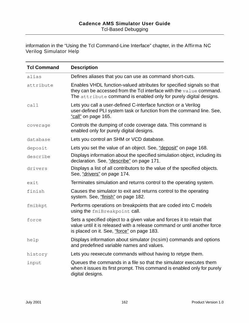
Cadence AMS Simulator User GuideTcl-Based Debugging
information in the “Using the Tcl Command-Line Interface” chapter, in the Affirma NCVerilog Simulator Help
Tcl Command Description
alias Defines aliases that you can use as command short-cuts.
attribute Enables VHDL function-valued attributes for specified signals so thatthey can be accessed from the Tcl interface with the value command.The attribute command is enabled only for purely digital designs.
call Lets you call a user-defined C-interface function or a Veriloguser-defined PLI system task or function from the command line. See,“call” on page 165.
coverage Controls the dumping of code coverage data. This command isenabled only for purely digital designs.
database Lets you control an SHM or VCD database.
deposit Lets you set the value of an object. See, “deposit” on page 168.
describe Displays information about the specified simulation object, including itsdeclaration. See, “describe” on page 171.
drivers Displays a list of all contributors to the value of the specified objects.See, “drivers” on page 174.
exit Terminates simulation and returns control to the operating system.
finish Causes the simulator to exit and returns control to the operatingsystem. See, “finish” on page 182.
fmibkpt Performs operations on breakpoints that are coded into C modelsusing the fmiBreakpoint call.
force Sets a specified object to a given value and forces it to retain thatvalue until it is released with a release command or until another forceis placed on it. See, “force” on page 183.
help Displays information about simulator (ncsim) commands and optionsand predefined variable names and values.
history Lets you reexecute commands without having to retype them.
input Queues the commands in a file so that the simulator executes themwhen it issues its first prompt. This command is enabled only for purelydigital designs.
July 2001 162 Product Version 1.0
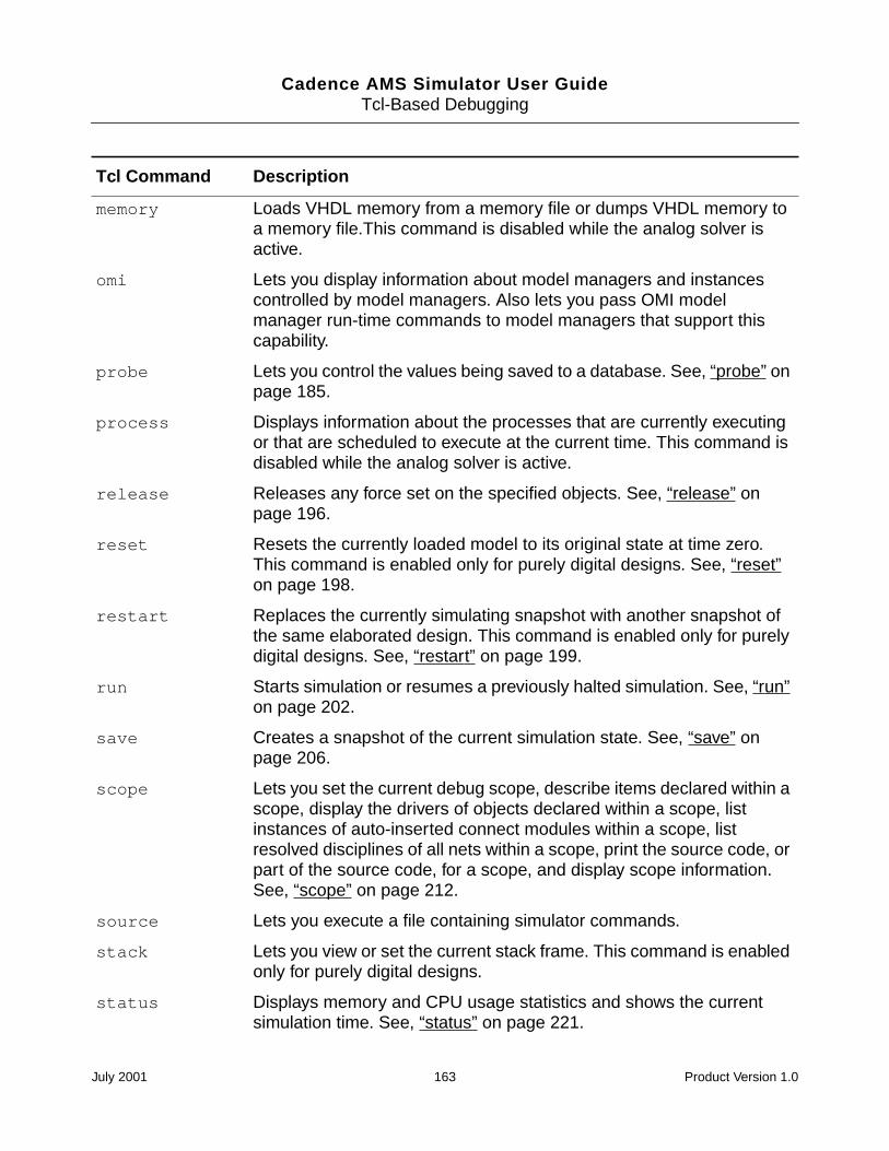
Cadence AMS Simulator User GuideTcl-Based Debugging
memory Loads VHDL memory from a memory file or dumps VHDL memory toa memory file.This command is disabled while the analog solver isactive.
omi Lets you display information about model managers and instancescontrolled by model managers. Also lets you pass OMI modelmanager run-time commands to model managers that support thiscapability.
probe Lets you control the values being saved to a database. See, “probe” onpage 185.
process Displays information about the processes that are currently executingor that are scheduled to execute at the current time. This command isdisabled while the analog solver is active.
release Releases any force set on the specified objects. See, “release” onpage 196.
reset Resets the currently loaded model to its original state at time zero.This command is enabled only for purely digital designs. See, “reset”on page 198.
restart Replaces the currently simulating snapshot with another snapshot ofthe same elaborated design. This command is enabled only for purelydigital designs. See, “restart” on page 199.
run Starts simulation or resumes a previously halted simulation. See, “run”on page 202.
save Creates a snapshot of the current simulation state. See, “save” onpage 206.
scope Lets you set the current debug scope, describe items declared within ascope, display the drivers of objects declared within a scope, listinstances of auto-inserted connect modules within a scope, listresolved disciplines of all nets within a scope, print the source code, orpart of the source code, for a scope, and display scope information.See, “scope” on page 212.
source Lets you execute a file containing simulator commands.
stack Lets you view or set the current stack frame. This command is enabledonly for purely digital designs.
status Displays memory and CPU usage statistics and shows the currentsimulation time. See, “status” on page 221.
Tcl Command Description
July 2001 163 Product Version 1.0
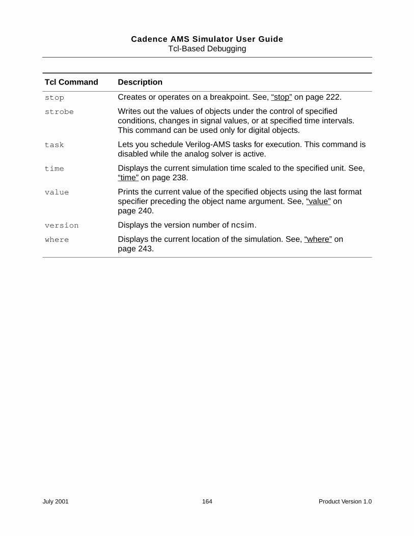
Cadence AMS Simulator User GuideTcl-Based Debugging
stop Creates or operates on a breakpoint. See, “stop” on page 222.
strobe Writes out the values of objects under the control of specifiedconditions, changes in signal values, or at specified time intervals.This command can be used only for digital objects.
task Lets you schedule Verilog-AMS tasks for execution. This command isdisabled while the analog solver is active.
time Displays the current simulation time scaled to the specified unit. See,“time” on page 238.
value Prints the current value of the specified objects using the last formatspecifier preceding the object name argument. See, “value” onpage 240.
version Displays the version number of ncsim.
where Displays the current location of the simulation. See, “where” onpage 243.
Tcl Command Description
July 2001 164 Product Version 1.0
Cadence AMS Simulator User GuideTcl-Based Debugging
call
The call command lets you call a user-defined or predefined VPI or system task or functionfrom the command line.
Note: In this release, you cannot call an analog VPI or system task or function. In addition,you cannot use the call command for digital tasks or functions while the analog solver isactive.
call Command Syntaxcall [-systf | -predefined] task_or_function_name [arg1 [arg2 ...]]
If you use the -systf or -predefined command option, the option must appear before thetask or function name or the simulator interprets it as an argument to the task or function. See“call Command Modifiers and Options” on page 167 for details on these options.
The task_or_function_name argument is the name of the system task or function with orwithout the beginning dollar sign. The dollar sign character has a special meaning in Tcl. Ifthe name of the task or function contains any dollar signs, you must enclose the argument incurly braces or precede each dollar sign by a backslash. For example, you can invoke asystem task or function called $mytask with:
ncsim> call mytask
ncsim> call \$mytask
ncsim> call $mytask
ncsim> call mytask
You can invoke a system task or function called $my$task with any of the following:
ncsim> call my\$task
ncsim> call \$my\$task
ncsim> call $my$task
ncsim> call my$task
Arguments to the system task or function can be either literals or names.
Literals can be:
Integers
ncsim> call mytask 5
ncsim> call mytask 5 7
Reals
ncsim> call mytask 3.4
ncsim> call mytask 22.928E+10
July 2001 165 Product Version 1.0
Cadence AMS Simulator User GuideTcl-Based Debugging
Strings
Strings must be enclosed in double quotes. Enclose strings in curly braces or use thebackslash character to escape quotes, spaces, and other characters that have specialmeaning to Tcl. For example:
ncsim> call mytask "hello world"
ncsim> call mytask \"hello\ world\"
Verilog literals, such as 8’h1f
Names can be full or relative path names of instances or objects. Relative path names arerelative to the current debug scope (set by the scope command). Object names can includea bit select or part select. For example:
ncsim> call mytask top.u1
ncsim> call mytask top.u1.reg[3:5]
Expressions that include operators or function calls are not allowed. For example, thefollowing two commands result in an error:
ncsim> call \$mytask a+b
ncsim> call \$mytask func a
However, literals can be created using Tcl’s expr command. For example, if the desiredargument is the expression (a+b), use the following:
ncsim> call \$mytask [expr #a + #b]
The result of the expression (a+b) is substituted on the command line and then treated bythe call command as a literal.
Note: The expr command cannot evaluate calls to Verilog functions.
If you are calling a user-defined system function, the result of the call command is the returnvalue from the system function. Therefore, user-defined system functions can be used togenerate literals for other commands. For example:
ncsim> call task [call func arg1 ...]
ncsim> force a = [call func arg1 ...]
July 2001 166 Product Version 1.0
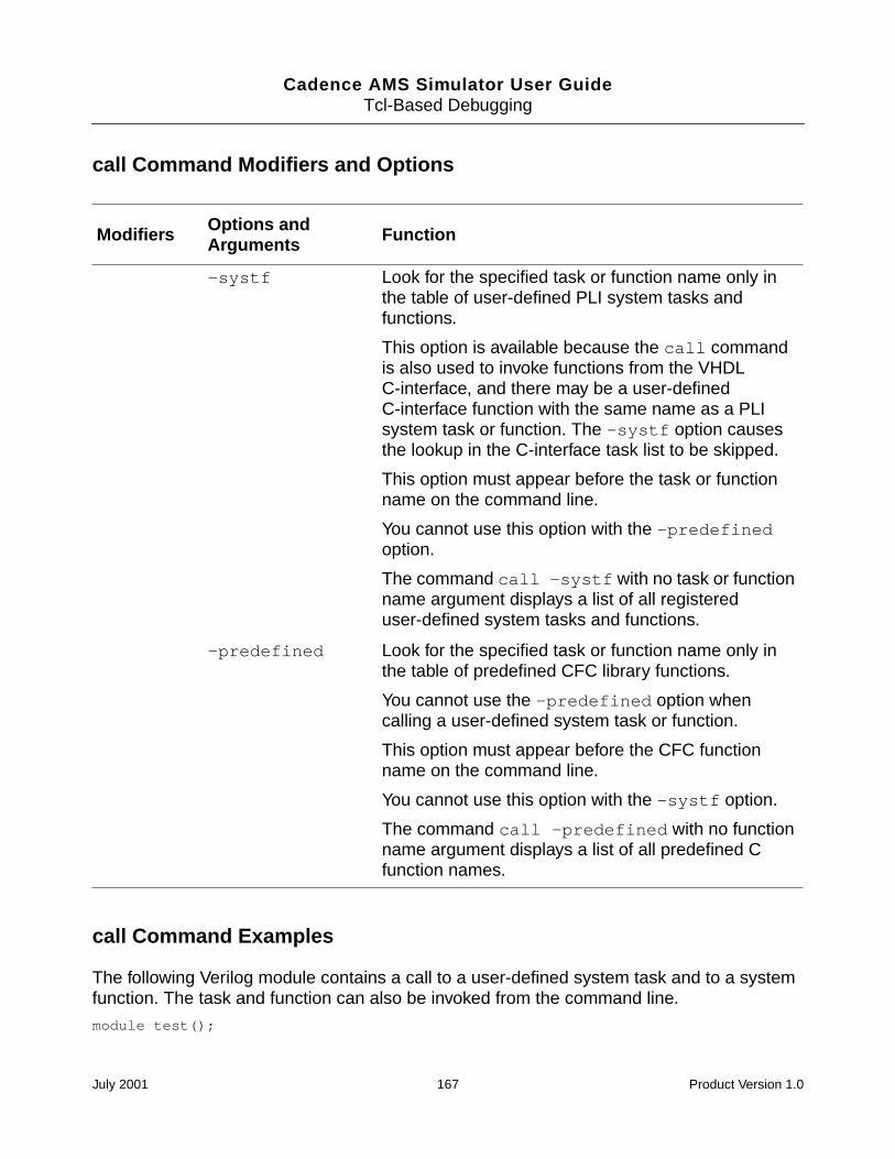
Cadence AMS Simulator User GuideTcl-Based Debugging
call Command Modifiers and Options
call Command Examples
The following Verilog module contains a call to a user-defined system task and to a systemfunction. The task and function can also be invoked from the command line.
module test();
Modifiers Options andArguments Function
-systf Look for the specified task or function name only inthe table of user-defined PLI system tasks andfunctions.
This option is available because the call commandis also used to invoke functions from the VHDLC-interface, and there may be a user-definedC-interface function with the same name as a PLIsystem task or function. The -systf option causesthe lookup in the C-interface task list to be skipped.
This option must appear before the task or functionname on the command line.
You cannot use this option with the -predefinedoption.
The command call -systf with no task or functionname argument displays a list of all registereduser-defined system tasks and functions.
-predefined Look for the specified task or function name only inthe table of predefined CFC library functions.
You cannot use the -predefined option whencalling a user-defined system task or function.
This option must appear before the CFC functionname on the command line.
You cannot use this option with the -systf option.
The command call -predefined with no functionname argument displays a list of all predefined Cfunction names.
July 2001 167 Product Version 1.0
Cadence AMS Simulator User GuideTcl-Based Debugging
initialbegin
$hello_task();$hello_task($hello_func());
end
endmodule
The following command invokes the $hello_task system task:
ncsim> call \$hello_task
This task can also be invoked with any of the following:
ncsim> call hello_task
ncsim> call $hello_task
ncsim> call hello_task
The $hello_func function can be invoked with any of the following commands:
ncsim> call \$hello_func
ncsim> call hello_func
ncsim> call $hello_func
ncsim> call hello_func
In the following command, the call command calls the $hello_task system task with acall to the system function $hello_func as an argument.
ncsim> call hello_task [call hello_func]
The following command displays a list of all registered user-defined system tasks andfunctions.
ncsim> call -systf
deposit
The deposit command lets you set the value of an object. Behaviors that are sensitive tovalue changes on the object run when the simulation resumes, just as if the value change wascaused by the Verilog or VHDL code.
Note: In this release, you cannot set the value of an analog object. In addition, you cannotuse the deposit command to set the value of digital objects while the analog solver is active.
The deposit command without a delay is similar to a force in that the specified value takeseffect and propagates immediately. However, it differs from a force in that future transactionson the signal are not blocked.
You can specify that the deposit is to take effect at a time in the future (-after -absolute)or after some amount of time has passed (-after -relative). In VHDL, a deposit with a
July 2001 168 Product Version 1.0
Cadence AMS Simulator User GuideTcl-Based Debugging
delay is different from Verilog in that it creates a transaction on a driver, much the same as aVHDL signal assignment statement. Use the -inertial or -transport option to depositthe value after an inertial delay or after a transport delay, respectively.
For VHDL, you can deposit to ports, signals, and variables if no delay is specified. If a delayis specified, you cannot deposit to variables or to signals with multiple sources.
For Verilog, you can deposit to ports, signals (wires and registers), and variables.
If the object is a memory or a range of memory elements, the specified value is deposited intoeach element of the memory or into each element in the specified range.
If the object is currently forced, the specified value appears on the object after the force isreleased, unless the release value is overwritten by another assignment in the meantime.
If the object is a register that is currently forced or assigned, the deposit command has noeffect.
The value assigned to the object must be a literal. The literal can be generated with Tcl valuesubstitution or command substitution. (See the “Verilog Value Substitution” and “CommandSubstitution” sections, in the “Basics of Tcl” appendix of the Affirma NC Verilog SimulatorHelp for details on Tcl substitution.)
For VHDL, the value specified with the deposit command must match the type and subtypeconstraints of the VHDL object. Integers, reals, physical types, enumeration types, andstrings (including std_logic_vector and bit_vector) are supported. Records and non-characterarray values are not supported, but objects of these types can be assigned to by issuingcommands for each subelement individually.
The object to which the value is to be deposited must have read/write access. An error isgenerated if the object does not have this access. See “Enabling Read, Write, or ConnectivityAccess to Digital Simulation Objects” on page 94 for details on specifying access tosimulation objects.
deposit Command Syntaxdeposit object_name [=] value
[-after time_spec -relative | -absolute][-inertial][-transport][-generic]
July 2001 169 Product Version 1.0
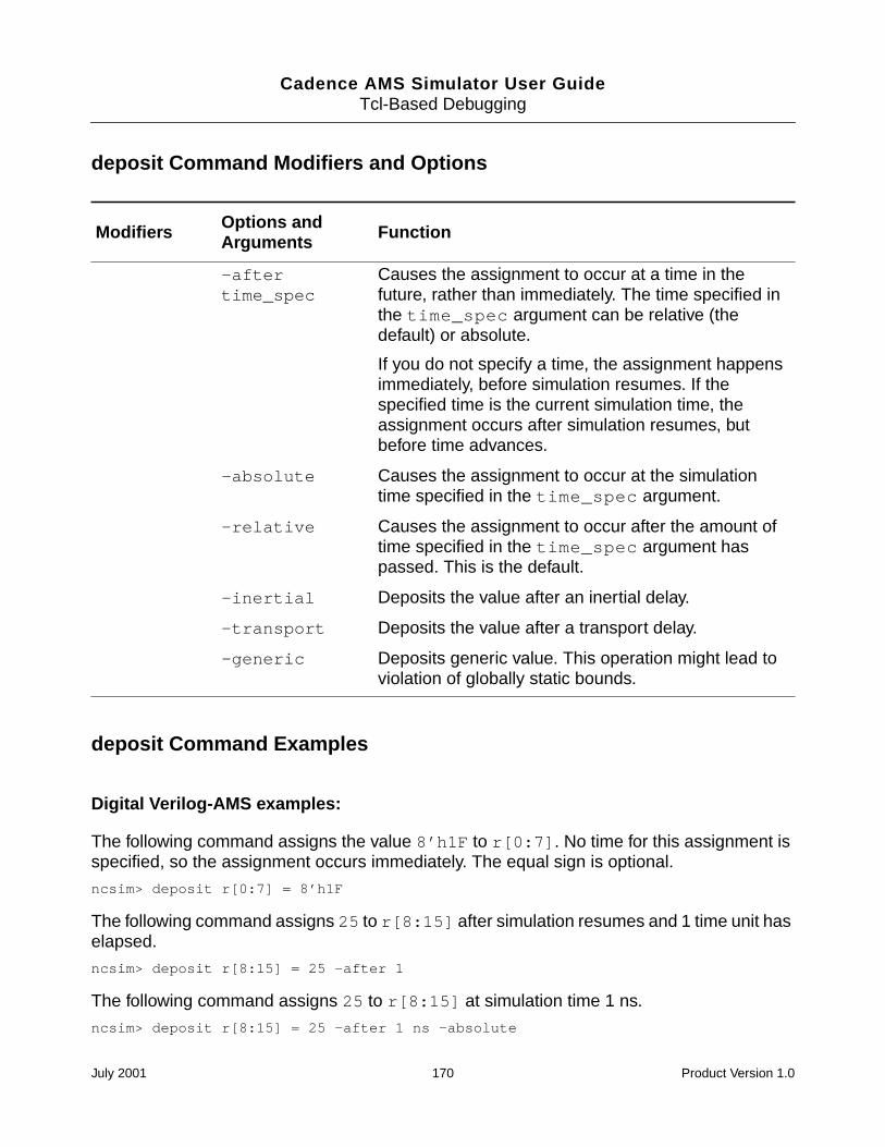
Cadence AMS Simulator User GuideTcl-Based Debugging
deposit Command Modifiers and Options
deposit Command Examples
Digital Verilog-AMS examples:
The following command assigns the value 8’h1F to r[0:7]. No time for this assignment isspecified, so the assignment occurs immediately. The equal sign is optional.
ncsim> deposit r[0:7] = 8’h1F
The following command assigns 25 to r[8:15] after simulation resumes and 1 time unit haselapsed.
ncsim> deposit r[8:15] = 25 -after 1
The following command assigns 25 to r[8:15] at simulation time 1 ns.
ncsim> deposit r[8:15] = 25 -after 1 ns -absolute
Modifiers Options andArguments Function
-aftertime_spec
Causes the assignment to occur at a time in thefuture, rather than immediately. The time specified inthe time_spec argument can be relative (thedefault) or absolute.
If you do not specify a time, the assignment happensimmediately, before simulation resumes. If thespecified time is the current simulation time, theassignment occurs after simulation resumes, butbefore time advances.
-absolute Causes the assignment to occur at the simulationtime specified in the time_spec argument.
-relative Causes the assignment to occur after the amount oftime specified in the time_spec argument haspassed. This is the default.
-inertial Deposits the value after an inertial delay.
-transport Deposits the value after a transport delay.
-generic Deposits generic value. This operation might lead toviolation of globally static bounds.
July 2001 170 Product Version 1.0
Cadence AMS Simulator User GuideTcl-Based Debugging
The following command sets the value of x to the current value of w. The assignment occursat simulation time 10 ns.
ncsim> deposit x = #w -after 10 ns -absolute
The following command uses both command and value substitution. The object y is set to thevalue returned by the Tcl expr command, which evaluates the expression #r[0] & ~#r[1]using the current value of r.
ncsim> deposit y = [expr #r[0] & ~#r[1]]
The following command shows the error message that is displayed if you run in regressionmode and then try to deposit a value to an object that does not have read/write access.
ncsim> deposit clrb 1ncsim: *E,RWACRQ: Object does not have read/write access:
hardrive.h1.clrb.
VHDL examples:
The following command deposits the value 1 to object :t_nickel_out (std_logic). Theequal sign is optional.
ncsim> deposit :t_nickel_out = ’1’
The following command deposits the value 1 to object :top:DISPENSE_tempsig(std_logic).
ncsim> deposit :top:DISPENSE_tempsig ’1’
The following command deposits the value 0 to object :t_dimes (std_logic_vector) after 10ns has elapsed.
ncsim> deposit -after 10 ns -relative :t_DIMES "00000000"
The following command deposits the value TRUE to object stoppit (boolean).
ncsim> deposit stoppit true
The following command deposits the value 10 to object :count (integer).
ncsim> deposit :count 10
describe
The describe command displays information about the specified simulation object,including its declaration.
For objects without read access, the output of the describe command does not includethe object’s value.
July 2001 171 Product Version 1.0
Cadence AMS Simulator User GuideTcl-Based Debugging
For objects that have read access but no write access, the string (-W) is included in theoutput.
For objects with neither read nor write access, the string (-RW) is included in the output.
For information about using describe with unnamed branches, see “Specifying UnnamedBranch Objects” on page 160.
See “Enabling Read, Write, or Connectivity Access to Digital Simulation Objects” on page 94for details on specifying access to simulation objects.
describe Command Syntaxdescribe simulation_object ...
describe Command Modifiers and Options
None.
describe Command Examples
Verilog-AMS examples:
The following command displays information about the Verilog-AMS analog net n1. Theresolved discipline is in parentheses. The value is the potential of the net.
ncsim> describe n1n1......wire (electrical) = 2.99227
The following command displays information about the Verilog-AMS digital net p1, which isbound to an input port.
ncsim> describe top.I3.clkSigtop.I3.clkSig...input (wire/tri) = St0
Both named and unnamed branches are described as branch, where the value is thepotential of the branch. For example,
ncsim> describe top.I4.compSig_groundtop.I4.compSig_ground...branch(compSig) = 0
The value is the potential of the branch. To see the flow through the branch, use the value-flow command instead.
The following command displays information about the Verilog object data.
July 2001 172 Product Version 1.0
Cadence AMS Simulator User GuideTcl-Based Debugging
ncsim> describe datadata......register [3:0] = 4’h0
The following command displays information about two Verilog objects: data and q.
ncsim> describe data qdata.......register [3:0] = 4’h0q..........wire [3:0]
q[3] (wire/tri) = StXq[2] (wire/tri) = StXq[1] (wire/tri) = StXq[0] (wire/tri) = StX
The following command displays information about the object alu_16.
ncsim> describe alu_16alu_16.....top-level module
The following command displays information about the object u1.
ncsim> describe u1u1.......instance of module arith
The following commands display information about the mixed bus w.
ncsim> describe ww..........wire (mixed bus) = Infncsim> describe w[0]w..........wire (electrical)ncsim> describe w[1]w..........wire [0:2]w[1] (wire/tri) = StXncsim> describe w[2]w..........wire [0:2]w[2] (wire/tri) = StX
The following command displays information about the connect module mya2d.
ncsim> describe mya2dmya2d........instance of connect module a2d
The following command shows the output of the describe command for an object that doesnot have read or write access. The output of the command does not include the object’s value,but the string (-RW).
ncsim> describe dd..........input [3:0]
d[3] (-RW)d[2] (-RW)d[1] (-RW)d[0] (-RW)
VHDL examples:ncsim> describe t_NICKEL_IN
t_NICKEL_IN...signal : std_logic = ’0’
ncsim> describe t_NICKEL_IN t_CANS
July 2001 173 Product Version 1.0
Cadence AMS Simulator User GuideTcl-Based Debugging
t_NICKEL_IN...signal : std_logic = ’0’
t_CANS........signal : std_logic_vector(7 downto 0) = "11111111"
ncsim> describe gen_dimes
gen_dimes...process statement
ncsim> describe :top
top........component instantiation
drivers
The drivers command displays a list of all contributors to the value of the specified digitalobject(s). You must specify at least one object.
Note: You cannot list drivers for analog nets, analog variables, or branches.
You can use the scope -drivers [scope_name] command to display the drivers of eachdigital object that is declared within a specified scope. See “scope” on page 212 for detailson the scope command.
For Verilog, the drivers command cannot find the drivers of a wire or register unless theobject has read and connectivity access. However, even if you have specified access to anobject, its drivers may have been collapsed, combined, or optimized away. In this case, theoutput of the command may indicate that the object has no drivers. See “Enabling Read,Write, or Connectivity Access to Digital Simulation Objects” on page 94 for details onspecifying access to simulation objects.
See “drivers Command Report Format” on page 175 for details on the output format of thedrivers command. See “drivers Command Examples” on page 179 for examples.
drivers Command Syntaxdrivers object_name ...
[-effective][-future][-novalue][-verbose]
July 2001 174 Product Version 1.0
Cadence AMS Simulator User GuideTcl-Based Debugging
drivers Command Modifiers and Options
drivers Command Report Format
Verilog Signals
The drivers report for digital Verilog-AMS signals is as follows:
value <- (scope) verilog_source_line_of_the_driver
For example:
af.........wire (wire/tri) = St1St1 <- (board.counter) assign altFifteen = &value
Instead of the verilog_source_line_of_the_driver, the following is output when theactual driver is from a VHDL model:
port ’port_name’ in module_name [File:path_to_file_containing_module], driven by a VHDL model.
Modifiers Options andArguments Function
-effective Displays contributions to the effective value of thesignal. By default, the drivers command displayscontributions to the driving value.
Only VHDL inout and linkage ports can havedifferent driving and effective values.
-future Displays the transactions that are scheduled oneach driver.
-novalue Suppresses the display of the current value of eachdriver.
-verbose Note: This option affects VHDL signals only.
Displays all of the processes (signal assignmentstatements), resolution functions, and typeconversion functions that contribute to the value ofthe specified signal.
If you don’t include the -verbose option, resolutionand type conversion function information is omittedfrom the output.
July 2001 175 Product Version 1.0
Cadence AMS Simulator User GuideTcl-Based Debugging
This report indicates that the signal is ultimately driven by a port (connected to port_nameof the specified module) on a module whose body is an imported VHDL model. Themodule_name corresponds to the module name of the shell being used to import the VHDLmodel.
VHDL Signals
The drivers report for VHDL signals is as follows:
description_of_signal = valuevalue_contributed_by_driver <- (scope_name) source_description
The source_description for the various kinds of drivers are shown below:
A Process
Nothing is generated for the source_description. This implies that a sequential signalassignment statement within a process is the driver. The scope_name is the scope name ofthe process.
Concurrent Signal Assignment/Concurrent Procedure call
The source_description is the VHDL source text of the concurrent signal assignmentstatement or concurrent procedure call that results in a driving value. This concurrentstatement is within the scope scope_name.
No drivers
If the signal has no drivers, the text No drivers appears verbatim.
A Verilog driver
If the driver is from a Verilog model, the report has the following form:
port ’port_name’ in entity(arch) [File:path_to_file_containing_entity], driven by a Verilog model.
This report indicates that the signal is ultimately driven by a port (connected to port_nameof the specified entity-architecture pair) on an entity whose body is an imported Verilogmodel.
July 2001 176 Product Version 1.0
Cadence AMS Simulator User GuideTcl-Based Debugging
Driver from a C model
If the driver is from an imported C model, the report has the following form:
port ’port_name’ in entity(arch) [File:path_to_file_containing_entity], driven by a C model.
Driver from a LMC model
If the driver is from an imported LMC model, the report has the following form:
port ’port_name’ in entity(arch) [File:path_to_file_containing_entity], driven by a LMC model.
Driver from an OMI model
If the driver is from an imported OMI model, the report has the following form:
port ’port_name’ in entity(arch) [File:path_to_shell_file], driven by a OMI model.
Resolution / Type Conversion Function in Non-Verbose mode
If you don’t use the -verbose option, the text [verbose report available ....]mayappear. This indicates that the signal gets its value from a resolution function or a typeconversion function. Use -verbose to display more information on the derivation of thesignal’s value.
On the next line of output (indented), a nonverbose driver report is displayed for each signalwhose driver contributes to the value of the signal in question.
Resolution Function
The following text is generated only when the -verbose option is used:
[resolution function function_name()]
This means that the signal is resolved with the named resolution function. A verbose driversreport is displayed (indented) for all inputs to the resolution function.
Type conversion on Formal of Port Association
The following text is generated only when the -verbose option is used:
[type conversion function function_name(formal)]
July 2001 177 Product Version 1.0
Cadence AMS Simulator User GuideTcl-Based Debugging
This means that the signal’s driving value comes from a type conversion function on a formalin a port association. A verbose drivers report is displayed (indented) for the formal port thatis the input to the function.
Type Conversion on Actual of Port Association
The following text is generated only when the -verbose option is used:
[type conversion function function_name(actual)]
This means that the signal’s effective value comes from a type conversion function on anactual in a port association. A verbose drivers report is displayed (indented) for the actual thatis the input to the function.
Implicit Guard Signal
The following text is displayed in response to a query on a signal whose value is computedfrom a GUARD expression:
[implicit guard signal]
Signal Attribute
The following is displayed in response to a query on an IN port that ultimately is associatedwith a signal valued attribute:
[attribute of signal full_path_of_the_signal]
The full_path_of_the_signal corresponds to the complete hierarchical path name ofthe signal whose attribute is the driver.
Constant Expression on a Port Association
The following is displayed when the value of the signal in question is from a constantexpression in a port map association:
[constant expression associated with port port_name]
Composite Signals
For a composite signal, a separate report is displayed for each group of subelements that canbe uniquely named and that have the same set of drivers.
July 2001 178 Product Version 1.0
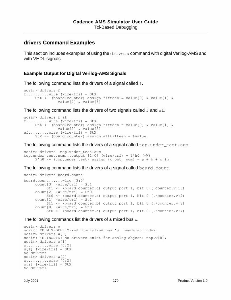
Cadence AMS Simulator User GuideTcl-Based Debugging
drivers Command Examples
This section includes examples of using the drivers command with digital Verilog-AMS andwith VHDL signals.
Example Output for Digital Verilog-AMS Signals
The following command lists the drivers of a signal called f.
ncsim> drivers ff..........wire (wire/tri) = StX
StX <- (board.counter) assign fifteen = value[0] & value[1] &value[2] & value[3]
The following command lists the drivers of two signals called f and af.
ncsim> drivers f aff..........wire (wire/tri) = StX
StX <- (board.counter) assign fifteen = value[0] & value[1] &value[2] & value[3]
af.........wire (wire/tri) = StXStX <- (board.counter) assign altFifteen = &value
The following command lists the drivers of a signal called top.under_test.sum.
ncsim> drivers top.under_test.sumtop.under_test.sum...output [1:0] (wire/tri) = 2’h0 (-W)
2’h0 <- (top.under_test) assign c_out, sum = a + b + c_in
The following command lists the drivers of a signal called board.count.
ncsim> drivers board.count
board.count......wire [3:0]count[3] (wire/tri) = St1
St1 <- (board.counter.d) output port 1, bit 0 (.counter.v:10)count[2] (wire/tri) = St0
St0 <- (board.counter.c) output port 1, bit 0 (./counter.v:9)count[1] (wire/tri) = St1
St1 <- (board.counter.b) output port 1, bit 0 (./counter.v:8)count[0] (wire/tri) = St0
St0 <- (board.counter.a) output port 1, bit 0 (./counter.v:7)
The following commands list the drivers of a mixed bus w.
ncsim> drivers wncsim: *E,MIXBOFF: Mixed discipline bus ’w’ needs an index.ncsim> drivers w[0]ncsim: *E,TNODIA: No drivers exist for analog object: top.w[0].ncsim> drivers w[1]w..........wire [0:2]w[1] (wire/tri) = StXNo driversncsim> drivers w[2]w..........wire [0:2]w[2] (wire/tri) = StXNo drivers
July 2001 179 Product Version 1.0
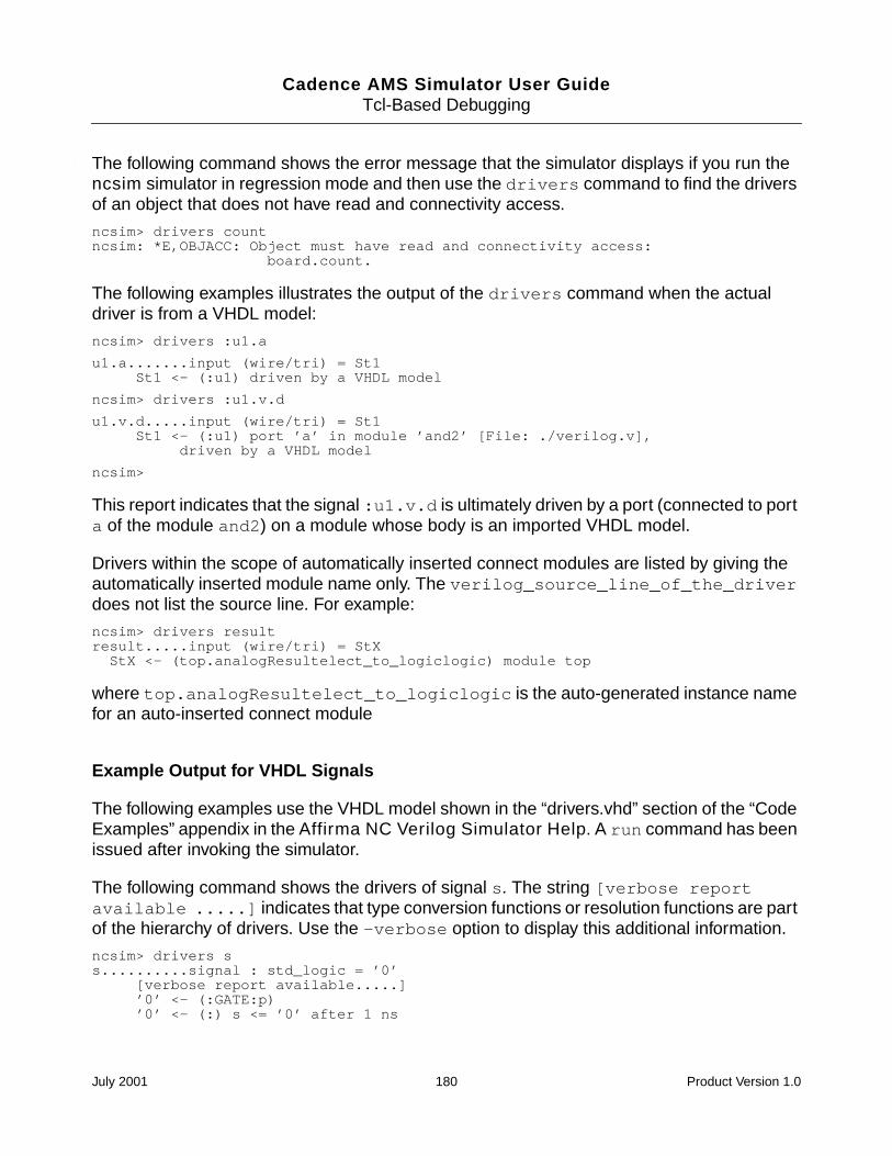
Cadence AMS Simulator User GuideTcl-Based Debugging
The following command shows the error message that the simulator displays if you run thencsim simulator in regression mode and then use the drivers command to find the driversof an object that does not have read and connectivity access.
ncsim> drivers countncsim: *E,OBJACC: Object must have read and connectivity access:
board.count.
The following examples illustrates the output of the drivers command when the actualdriver is from a VHDL model:
ncsim> drivers :u1.a
u1.a.......input (wire/tri) = St1St1 <- (:u1) driven by a VHDL model
ncsim> drivers :u1.v.d
u1.v.d.....input (wire/tri) = St1St1 <- (:u1) port ’a’ in module ’and2’ [File: ./verilog.v],
driven by a VHDL model
ncsim>
This report indicates that the signal :u1.v.d is ultimately driven by a port (connected to porta of the module and2) on a module whose body is an imported VHDL model.
Drivers within the scope of automatically inserted connect modules are listed by giving theautomatically inserted module name only. The verilog_source_line_of_the_driverdoes not list the source line. For example:
ncsim> drivers resultresult.....input (wire/tri) = StXStX <- (top.analogResultelect_to_logiclogic) module top
where top.analogResultelect_to_logiclogic is the auto-generated instance namefor an auto-inserted connect module
Example Output for VHDL Signals
The following examples use the VHDL model shown in the “drivers.vhd” section of the “CodeExamples” appendix in the Affirma NC Verilog Simulator Help. A run command has beenissued after invoking the simulator.
The following command shows the drivers of signal s. The string [verbose reportavailable .....] indicates that type conversion functions or resolution functions are partof the hierarchy of drivers. Use the -verbose option to display this additional information.
ncsim> drivers ss..........signal : std_logic = ’0’
[verbose report available.....]’0’ <- (:GATE:p)’0’ <- (:) s <= ’0’ after 1 ns
July 2001 180 Product Version 1.0
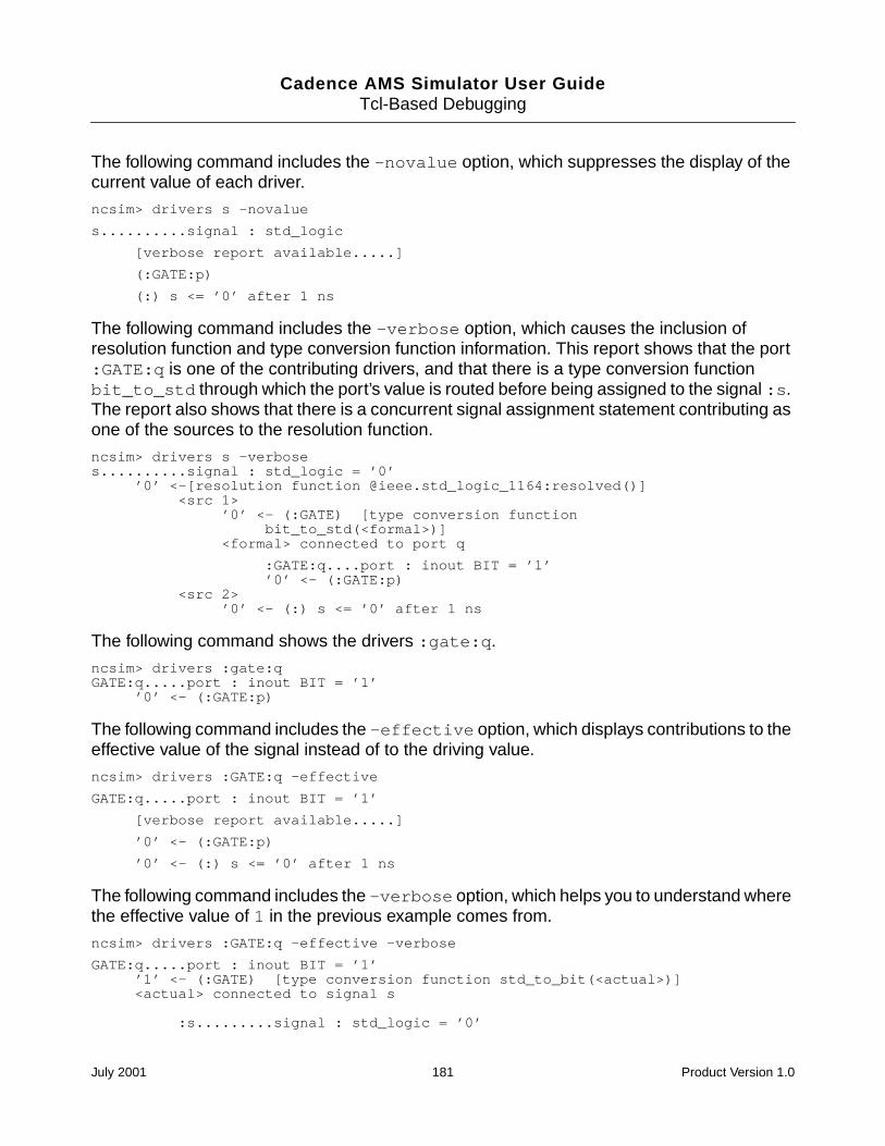
Cadence AMS Simulator User GuideTcl-Based Debugging
The following command includes the -novalue option, which suppresses the display of thecurrent value of each driver.
ncsim> drivers s -novalue
s..........signal : std_logic
[verbose report available.....]
(:GATE:p)
(:) s <= ’0’ after 1 ns
The following command includes the -verbose option, which causes the inclusion ofresolution function and type conversion function information. This report shows that the port:GATE:q is one of the contributing drivers, and that there is a type conversion functionbit_to_std through which the port’s value is routed before being assigned to the signal :s.The report also shows that there is a concurrent signal assignment statement contributing asone of the sources to the resolution function.
ncsim> drivers s -verboses..........signal : std_logic = ’0’
’0’ <-[resolution function @ieee.std_logic_1164:resolved()]<src 1>
’0’ <- (:GATE) [type conversion functionbit_to_std(<formal>)]
<formal> connected to port q
:GATE:q....port : inout BIT = ’1’’0’ <- (:GATE:p)
<src 2>’0’ <- (:) s <= ’0’ after 1 ns
The following command shows the drivers :gate:q.
ncsim> drivers :gate:qGATE:q.....port : inout BIT = ’1’
’0’ <- (:GATE:p)
The following command includes the -effective option, which displays contributions to theeffective value of the signal instead of to the driving value.
ncsim> drivers :GATE:q -effective
GATE:q.....port : inout BIT = ’1’
[verbose report available.....]
’0’ <- (:GATE:p)
’0’ <- (:) s <= ’0’ after 1 ns
The following command includes the -verbose option, which helps you to understand wherethe effective value of 1 in the previous example comes from.
ncsim> drivers :GATE:q -effective -verbose
GATE:q.....port : inout BIT = ’1’’1’ <- (:GATE) [type conversion function std_to_bit(<actual>)]<actual> connected to signal s
:s.........signal : std_logic = ’0’
July 2001 181 Product Version 1.0
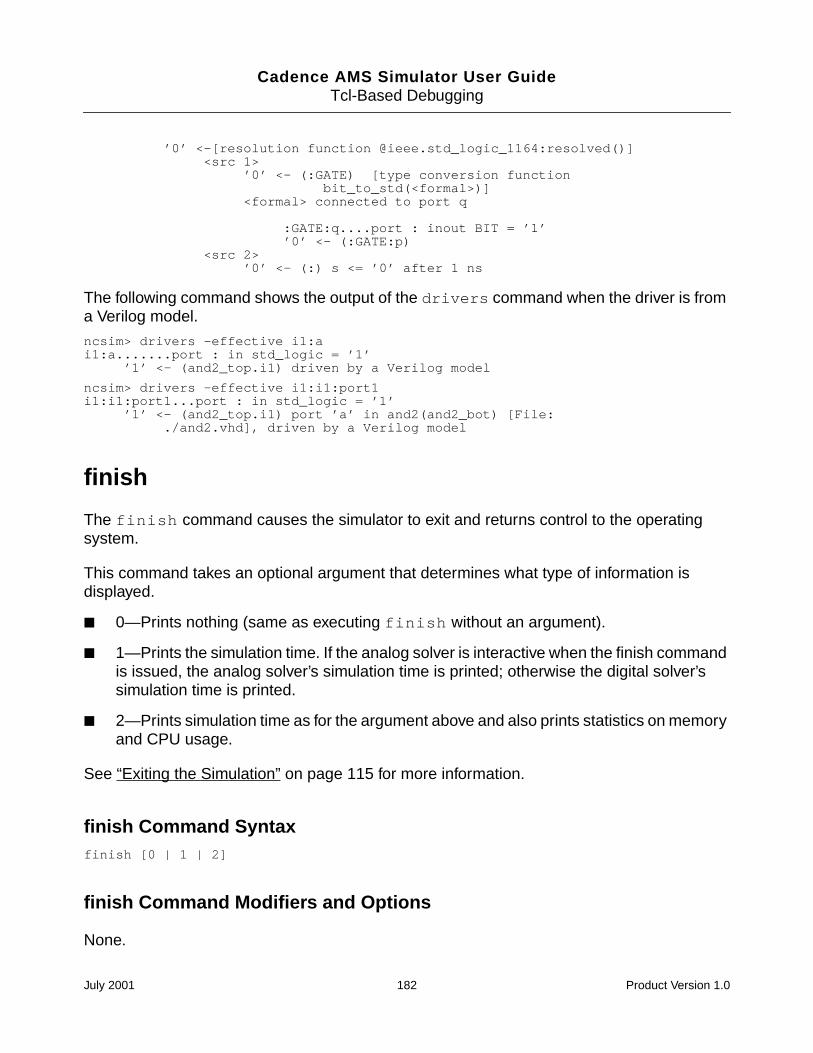
Cadence AMS Simulator User GuideTcl-Based Debugging
’0’ <-[resolution function @ieee.std_logic_1164:resolved()]<src 1>
’0’ <- (:GATE) [type conversion functionbit_to_std(<formal>)]
<formal> connected to port q
:GATE:q....port : inout BIT = ’1’’0’ <- (:GATE:p)
<src 2>’0’ <- (:) s <= ’0’ after 1 ns
The following command shows the output of the drivers command when the driver is froma Verilog model.
ncsim> drivers -effective i1:ai1:a.......port : in std_logic = ’1’
’1’ <- (and2_top.i1) driven by a Verilog model
ncsim> drivers -effective i1:i1:port1i1:i1:port1...port : in std_logic = ’1’
’1’ <- (and2_top.i1) port ’a’ in and2(and2_bot) [File:./and2.vhd], driven by a Verilog model
finish
The finish command causes the simulator to exit and returns control to the operatingsystem.
This command takes an optional argument that determines what type of information isdisplayed.
0—Prints nothing (same as executing finish without an argument).
1—Prints the simulation time. If the analog solver is interactive when the finish commandis issued, the analog solver’s simulation time is printed; otherwise the digital solver’ssimulation time is printed.
2—Prints simulation time as for the argument above and also prints statistics on memoryand CPU usage.
See “Exiting the Simulation” on page 115 for more information.
finish Command Syntaxfinish [0 | 1 | 2]
finish Command Modifiers and Options
None.
July 2001 182 Product Version 1.0
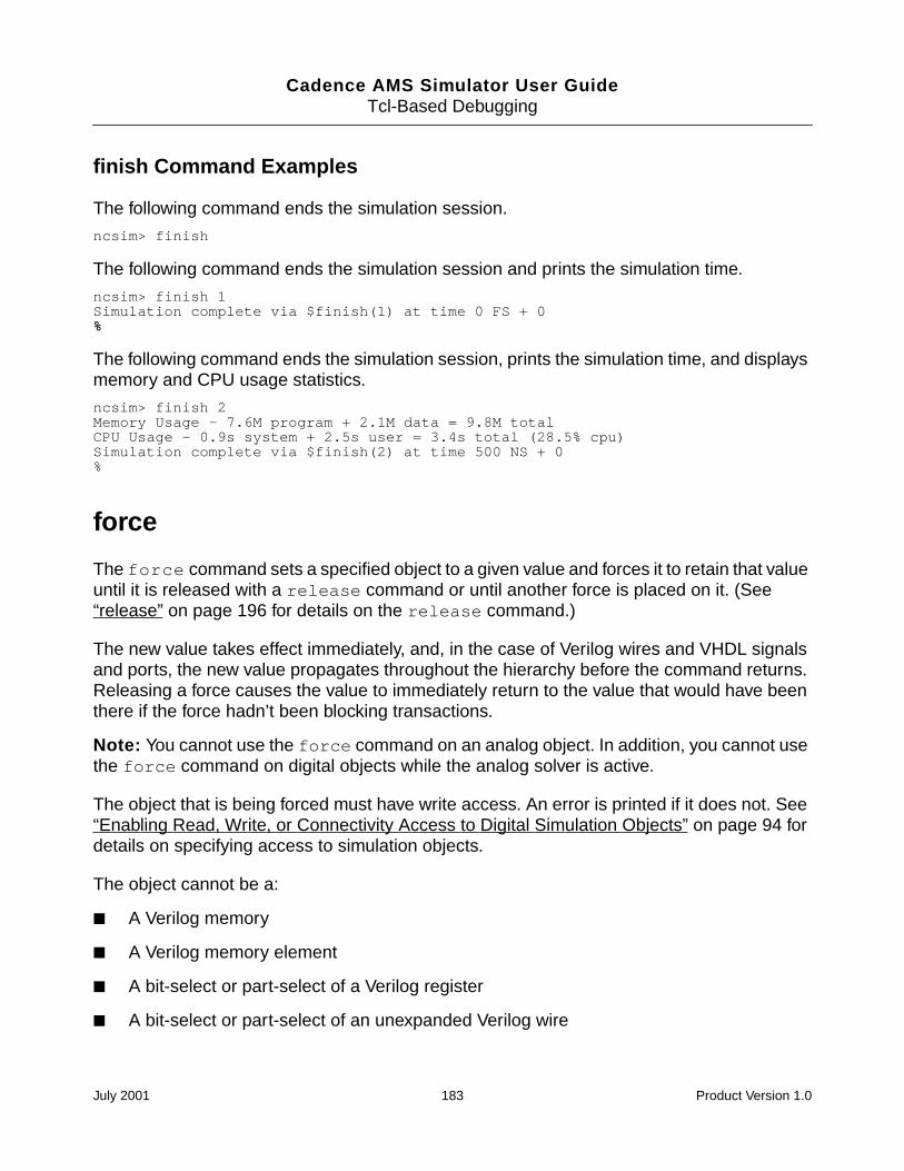
Cadence AMS Simulator User GuideTcl-Based Debugging
finish Command Examples
The following command ends the simulation session.
ncsim> finish
The following command ends the simulation session and prints the simulation time.
ncsim> finish 1Simulation complete via $finish(1) at time 0 FS + 0%
The following command ends the simulation session, prints the simulation time, and displaysmemory and CPU usage statistics.
ncsim> finish 2Memory Usage - 7.6M program + 2.1M data = 9.8M totalCPU Usage - 0.9s system + 2.5s user = 3.4s total (28.5% cpu)Simulation complete via $finish(2) at time 500 NS + 0%
force
The force command sets a specified object to a given value and forces it to retain that valueuntil it is released with a release command or until another force is placed on it. (See“release” on page 196 for details on the release command.)
The new value takes effect immediately, and, in the case of Verilog wires and VHDL signalsand ports, the new value propagates throughout the hierarchy before the command returns.Releasing a force causes the value to immediately return to the value that would have beenthere if the force hadn’t been blocking transactions.
Note: You cannot use the force command on an analog object. In addition, you cannot usethe force command on digital objects while the analog solver is active.
The object that is being forced must have write access. An error is printed if it does not. See“Enabling Read, Write, or Connectivity Access to Digital Simulation Objects” on page 94 fordetails on specifying access to simulation objects.
The object cannot be a:
A Verilog memory
A Verilog memory element
A bit-select or part-select of a Verilog register
A bit-select or part-select of an unexpanded Verilog wire
July 2001 183 Product Version 1.0
Cadence AMS Simulator User GuideTcl-Based Debugging
A VHDL variable
For Verilog, a force created by the force command is identical in behavior to a force createdby a Verilog force procedural statement. The force can be released by a Verilog releasestatement or replaced by a Verilog force statement during subsequent simulation.
The value must be a literal, and the literal is treated as a constant. Even if the literal isgenerated using value substitution or Tcl’s expr command, the value is considered to be aconstant. The forced value does not change if objects used to generate the literal changevalue during subsequent simulation.
For VHDL, the value specified with the force command must match the type and subtypeconstraints of the VHDL object. Integers, reals, physical types, enumeration types, andstrings (including std_logic_vector and bit_vector) are supported. Records and non-characterarray values are not supported, but objects of these types can be assigned to by issuingcommands for each subelement individually.
Forces created by the force command and those created by a Verilog force proceduralstatements are saved if the simulation is saved.
See the “Forcing and Releasing Signal Values” section in the “Debugging Your Design”chapter of the Affirma NC Verilog Simulator Help for more information.
See the “Basics of Tcl” appendix in the Affirma NC Verilog Simulator Help for informationon using Tcl with NC-Verilog.
force Command Syntaxforce object_name [=] value
force Command Modifiers and Options
None.
force Command Examples
Digital Verilog-AMS examples:
The following command forces object r to the value ‘bx. The equal sign is optional.
ncsim> force r = ‘bx
The following command uses value substitution. Object x is forced to the current value of w.
July 2001 184 Product Version 1.0
Cadence AMS Simulator User GuideTcl-Based Debugging
ncsim> force x = #w
The following command uses command substitution and value substitution. Object y is forcedto the result of the Tcl expr command, which evaluates the expression #r[0] & ~#r[1]using the current value of r.
ncsim> force y [expr #r[0] & ~#r[1]]
The following command shows the error message that is displayed if you run in regressionmode and then use the force command on an object that does not have write access.
ncsim> force clrb 1ncsim: *E,RWACRQ: Object does not have read/write access:
hardrive.h1.clrb.
VHDL examples:
The following command forces object :t_nickel_out (std_logic) to 1. The equal sign isoptional.
ncsim> force :t_nickel_out = ’1’
The following command forces object :top:DISPENSE_tempsig (std_logic) to 1.
ncsim> force :top:DISPENSE_tempsig ’1’
The following command forces object :t_dimes (std_logic_vector) to 0.
ncsim> force :t_DIMES "00000000"
The following command forces object is_ok (boolean) to TRUE.
ncsim> force :is_ok true
The following command forces object :count (integer) to 10.
ncsim> force :count 10
probe
The probe command lets you control the values being saved to a database. You can:
Create probes (with the optional -create modifier)
Delete probes (-delete)
Disable probes (-disable)
Enable previously disabled probes (-enable)
Display information about probes (-show)
July 2001 185 Product Version 1.0
Cadence AMS Simulator User GuideTcl-Based Debugging
Note: You can use the probe command only for digital objects. If you explicitly specify anyanalog argument objects, the probe command ignores them and the simulator issues awarning. The probe command also ignores any analog objects selected by the -all,-inputs, -outputs, and -ports arguments but does not issue any warning.
Note: In the current release, you cannot use the probe command to probe VHDL objects toa VCD database. You can create a VCD database for VHDL objects by using the callcommand to call predefined CFC routines, which are part of the NC VHDL simulator Cinterface. See “call” on page 165 for details on the call command. See Appendix B, “VCDFormat Output,” in the Affirma NC VHDL Simulator Help for information on VCD files.
With an SHM database, you can probe all VHDL signals, ports, and variables that are notdeclared inside subprograms unless their type falls into one of the following categories:
Non-standard integer types whose bounds require more than 32 bits to represent
Physical types
Access and file types
Any composite type that contains one of the above types
For digital Verilog-AMS, probes are created only for objects that have read access. If youspecify an object as an argument to the probe command, and that object does not have readaccess, an error message is printed. If you specify a scope as an argument to the probecommand, objects within that scope that do not have read access are excluded from theprobe and a warning message is printed. See “Enabling Read, Write, or Connectivity Accessto Digital Simulation Objects” on page 94 for details on specifying access to simulationobjects.
July 2001 186 Product Version 1.0
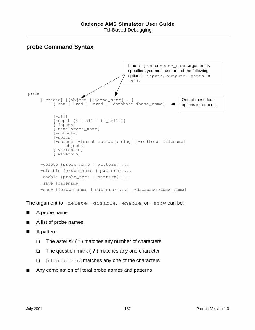
Cadence AMS Simulator User GuideTcl-Based Debugging
probe Command Syntax
The argument to -delete, -disable, -enable, or -show can be:
A probe name
A list of probe names
A pattern
The asterisk ( * ) matches any number of characters
The question mark ( ? ) matches any one character
[characters] matches any one of the characters
Any combination of literal probe names and patterns
probe
[-create] [object | scope_name...]-shm | -vcd | -evcd | -database dbase_name
[-all][-depth n | all | to_cells][-inputs][-name probe_name][-outputs][-ports][-screen [-format format_string] [-redirect filename]
objects][-variables][-waveform]
-delete probe_name | pattern ...
-disable probe_name | pattern ...
-enable probe_name | pattern ...
-save [filename]
-show [probe_name | pattern ...] [-database dbase_name]
If no object or scope_name argument isspecified, you must use one of the followingoptions: -inputs,-outputs, -ports, or-all.
One of these fouroptions is required.
July 2001 187 Product Version 1.0
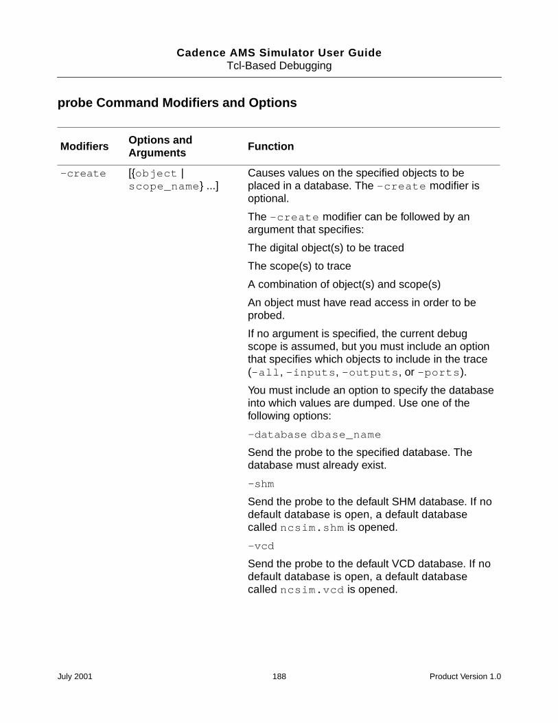
Cadence AMS Simulator User GuideTcl-Based Debugging
probe Command Modifiers and Options
Modifiers Options andArguments Function
-create [object |scope_name ...]
Causes values on the specified objects to beplaced in a database. The -create modifier isoptional.
The -create modifier can be followed by anargument that specifies:
The digital object(s) to be traced
The scope(s) to trace
A combination of object(s) and scope(s)
An object must have read access in order to beprobed.
If no argument is specified, the current debugscope is assumed, but you must include an optionthat specifies which objects to include in the trace(-all, -inputs, -outputs, or -ports).
You must include an option to specify the databaseinto which values are dumped. Use one of thefollowing options:
-database dbase_name
Send the probe to the specified database. Thedatabase must already exist.
-shm
Send the probe to the default SHM database. If nodefault database is open, a default databasecalled ncsim.shm is opened.
-vcd
Send the probe to the default VCD database. If nodefault database is open, a default databasecalled ncsim.vcd is opened.
July 2001 188 Product Version 1.0
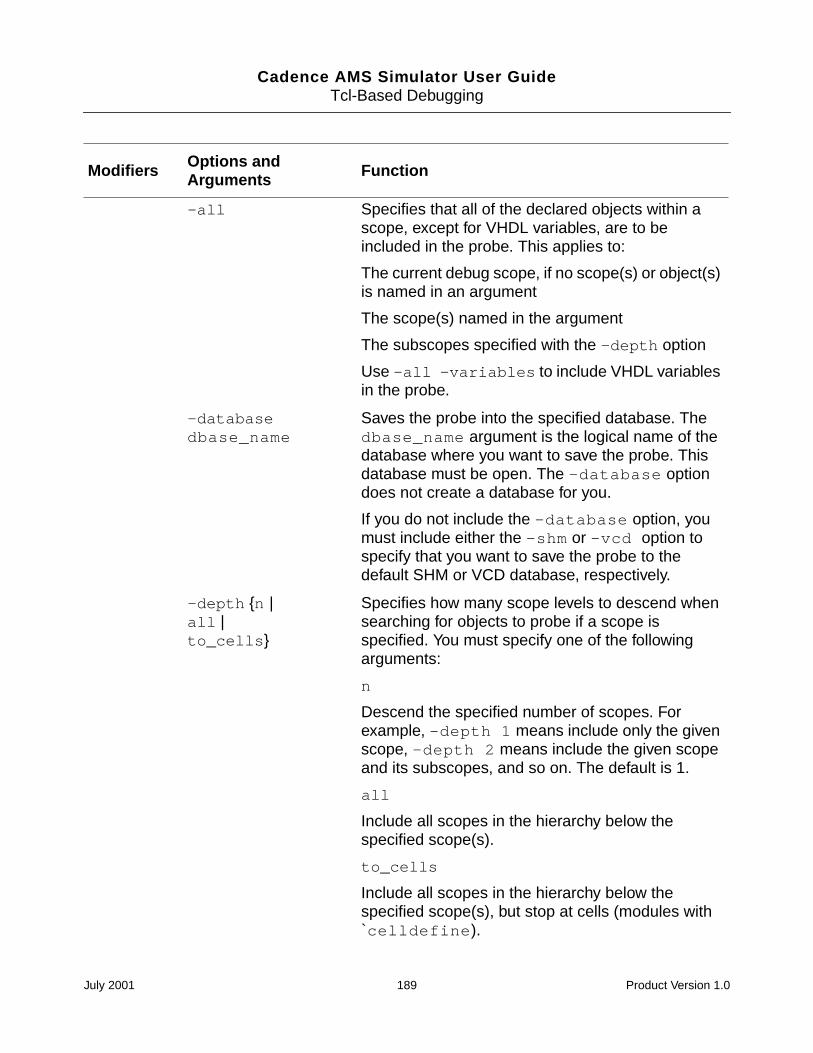
Cadence AMS Simulator User GuideTcl-Based Debugging
-all Specifies that all of the declared objects within ascope, except for VHDL variables, are to beincluded in the probe. This applies to:
The current debug scope, if no scope(s) or object(s)is named in an argument
The scope(s) named in the argument
The subscopes specified with the -depth option
Use -all -variables to include VHDL variablesin the probe.
-databasedbase_name
Saves the probe into the specified database. Thedbase_name argument is the logical name of thedatabase where you want to save the probe. Thisdatabase must be open. The -database optiondoes not create a database for you.
If you do not include the -database option, youmust include either the -shm or -vcd option tospecify that you want to save the probe to thedefault SHM or VCD database, respectively.
-depth n |all |to_cells
Specifies how many scope levels to descend whensearching for objects to probe if a scope isspecified. You must specify one of the followingarguments:
n
Descend the specified number of scopes. Forexample, -depth 1 means include only the givenscope, -depth 2 means include the given scopeand its subscopes, and so on. The default is 1.
all
Include all scopes in the hierarchy below thespecified scope(s).
to_cells
Include all scopes in the hierarchy below thespecified scope(s), but stop at cells (modules with`celldefine).
Modifiers Options andArguments Function
July 2001 189 Product Version 1.0
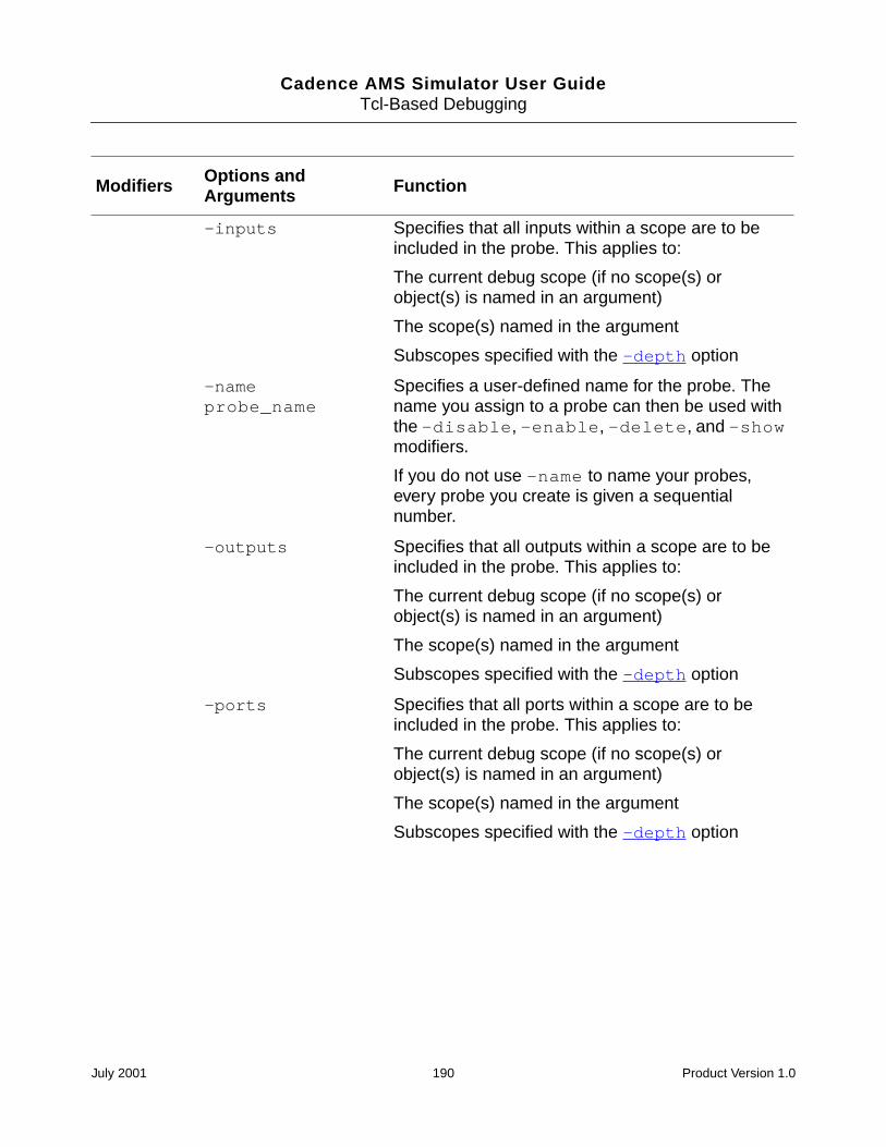
Cadence AMS Simulator User GuideTcl-Based Debugging
-inputs Specifies that all inputs within a scope are to beincluded in the probe. This applies to:
The current debug scope (if no scope(s) orobject(s) is named in an argument)
The scope(s) named in the argument
Subscopes specified with the -depth option
-nameprobe_name
Specifies a user-defined name for the probe. Thename you assign to a probe can then be used withthe -disable, -enable, -delete, and -showmodifiers.
If you do not use -name to name your probes,every probe you create is given a sequentialnumber.
-outputs Specifies that all outputs within a scope are to beincluded in the probe. This applies to:
The current debug scope (if no scope(s) orobject(s) is named in an argument)
The scope(s) named in the argument
Subscopes specified with the -depth option
-ports Specifies that all ports within a scope are to beincluded in the probe. This applies to:
The current debug scope (if no scope(s) orobject(s) is named in an argument)
The scope(s) named in the argument
Subscopes specified with the -depth option
Modifiers Options andArguments Function
July 2001 190 Product Version 1.0
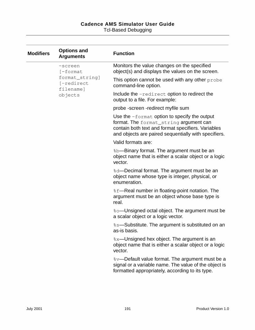
Cadence AMS Simulator User GuideTcl-Based Debugging
-screen[-formatformat_string][-redirectfilename]objects
Monitors the value changes on the specifiedobject(s) and displays the values on the screen.
This option cannot be used with any other probecommand-line option.
Include the -redirect option to redirect theoutput to a file. For example:
probe -screen -redirect myfile sum
Use the -format option to specify the outputformat. The format_string argument cancontain both text and format specifiers. Variablesand objects are paired sequentially with specifiers.
Valid formats are:
%b—Binary format. The argument must be anobject name that is either a scalar object or a logicvector.
%d—Decimal format. The argument must be anobject name whose type is integer, physical, orenumeration.
%f—Real number in floating-point notation. Theargument must be an object whose base type isreal.
%o—Unsigned octal object. The argument must bea scalar object or a logic vector.
%s—Substitute. The argument is substituted on anas-is basis.
%x—Unsigned hex object. The argument is anobject name that is either a scalar object or a logicvector.
%v—Default value format. The argument must be asignal or a variable name. The value of the object isformatted appropriately, according to its type.
Modifiers Options andArguments Function
July 2001 191 Product Version 1.0
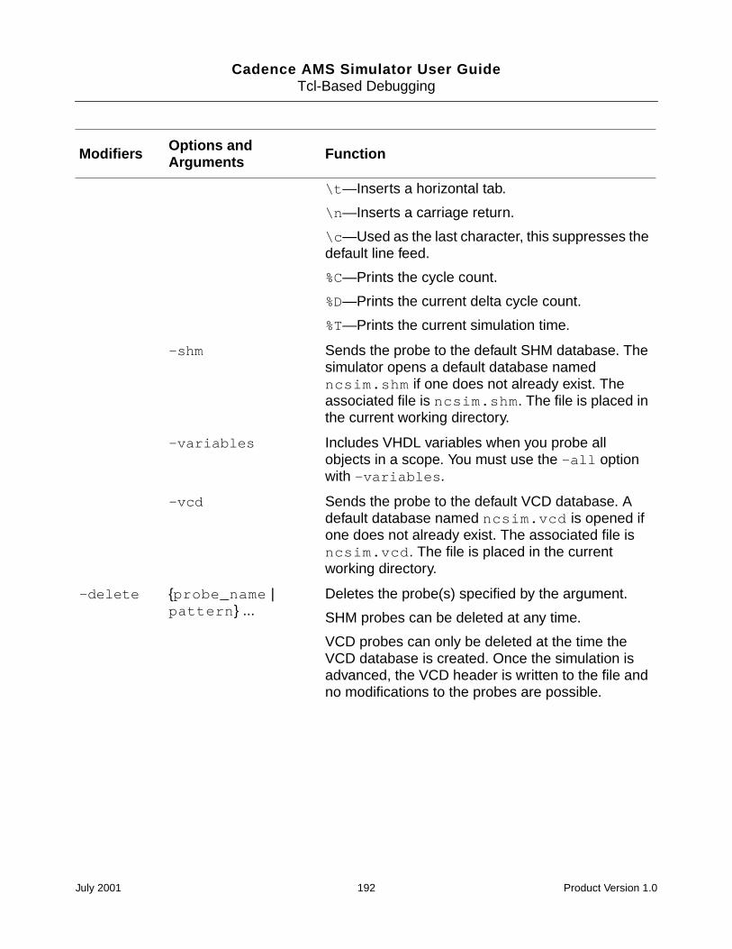
Cadence AMS Simulator User GuideTcl-Based Debugging
\t—Inserts a horizontal tab.
\n—Inserts a carriage return.
\c—Used as the last character, this suppresses thedefault line feed.
%C—Prints the cycle count.
%D—Prints the current delta cycle count.
%T—Prints the current simulation time.
-shm Sends the probe to the default SHM database. Thesimulator opens a default database namedncsim.shm if one does not already exist. Theassociated file is ncsim.shm. The file is placed inthe current working directory.
-variables Includes VHDL variables when you probe allobjects in a scope. You must use the -all optionwith -variables.
-vcd Sends the probe to the default VCD database. Adefault database named ncsim.vcd is opened ifone does not already exist. The associated file isncsim.vcd. The file is placed in the currentworking directory.
-delete probe_name |pattern ...
Deletes the probe(s) specified by the argument.
SHM probes can be deleted at any time.
VCD probes can only be deleted at the time theVCD database is created. Once the simulation isadvanced, the VCD header is written to the file andno modifications to the probes are possible.
Modifiers Options andArguments Function
July 2001 192 Product Version 1.0
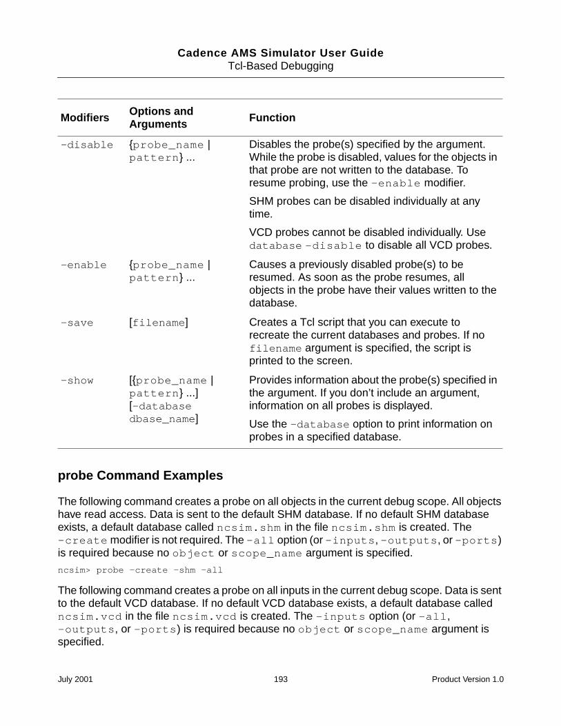
Cadence AMS Simulator User GuideTcl-Based Debugging
probe Command Examples
The following command creates a probe on all objects in the current debug scope. All objectshave read access. Data is sent to the default SHM database. If no default SHM databaseexists, a default database called ncsim.shm in the file ncsim.shm is created. The-create modifier is not required. The -all option (or -inputs, -outputs, or -ports)is required because no object or scope_name argument is specified.
ncsim> probe -create -shm -all
The following command creates a probe on all inputs in the current debug scope. Data is sentto the default VCD database. If no default VCD database exists, a default database calledncsim.vcd in the file ncsim.vcd is created. The -inputs option (or -all,-outputs, or -ports) is required because no object or scope_name argument isspecified.
-disable probe_name |pattern ...
Disables the probe(s) specified by the argument.While the probe is disabled, values for the objects inthat probe are not written to the database. Toresume probing, use the -enable modifier.
SHM probes can be disabled individually at anytime.
VCD probes cannot be disabled individually. Usedatabase -disable to disable all VCD probes.
-enable probe_name |pattern ...
Causes a previously disabled probe(s) to beresumed. As soon as the probe resumes, allobjects in the probe have their values written to thedatabase.
-save [filename] Creates a Tcl script that you can execute torecreate the current databases and probes. If nofilename argument is specified, the script isprinted to the screen.
-show [probe_name |pattern ...][-databasedbase_name]
Provides information about the probe(s) specified inthe argument. If you don’t include an argument,information on all probes is displayed.
Use the -database option to print information onprobes in a specified database.
Modifiers Options andArguments Function
July 2001 193 Product Version 1.0
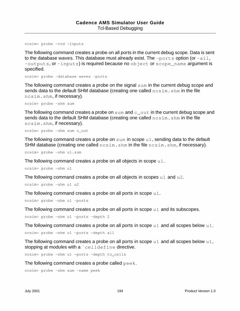
Cadence AMS Simulator User GuideTcl-Based Debugging
ncsim> probe -vcd -inputs
The following command creates a probe on all ports in the current debug scope. Data is sentto the database waves. This database must already exist. The -ports option (or -all,-outputs, or -inputs) is required because no object or scope_name argument isspecified.
ncsim> probe -database waves -ports
The following command creates a probe on the signal sum in the current debug scope andsends data to the default SHM database (creating one called ncsim.shm in the filencsim.shm, if necessary).
ncsim> probe -shm sum
The following command creates a probe on sum and c_out in the current debug scope andsends data to the default SHM database (creating one called ncsim.shm in the filencsim.shm, if necessary).
ncsim> probe -shm sum c_out
The following command creates a probe on sum in scope u1, sending data to the defaultSHM database (creating one called ncsim.shm in the file ncsim.shm, if necessary).
ncsim> probe -shm u1.sum
The following command creates a probe on all objects in scope u1.
ncsim> probe -shm u1
The following command creates a probe on all objects in scopes u1 and u2.
ncsim> probe -shm u1 u2
The following command creates a probe on all ports in scope u1.
ncsim> probe -shm u1 -ports
The following command creates a probe on all ports in scope u1 and its subscopes.
ncsim> probe -shm u1 -ports -depth 2
The following command creates a probe on all ports in scope u1 and all scopes below u1.
ncsim> probe -shm u1 -ports -depth all
The following command creates a probe on all ports in scope u1 and all scopes below u1,stopping at modules with a `celldefine directive.
ncsim> probe -shm u1 -ports -depth to_cells
The following command creates a probe called peek.
ncsim> probe -shm sum -name peek
July 2001 194 Product Version 1.0
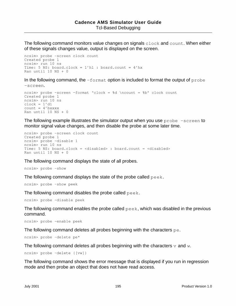
Cadence AMS Simulator User GuideTcl-Based Debugging
The following command monitors value changes on signals clock and count. When eitherof these signals changes value, output is displayed on the screen.
ncsim> probe -screen clock countCreated probe 1ncsim> run 10 nsTime: 5 NS: board.clock = 1’h1 : board.count = 4’hxRan until 10 NS + 0
In the following command, the -format option is included to format the output of probe-screen.
ncsim> probe -screen -format "clock = %d \ncount = %b" clock countCreated probe 1ncsim> run 10 nsclock = 1’d1count = 4’bxxxxRan until 10 NS + 0
The following example illustrates the simulator output when you use probe -screen tomonitor signal value changes, and then disable the probe at some later time.
ncsim> probe -screen clock countCreated probe 1ncsim> probe -disable 1ncsim> run 10 nsTime: 5 NS: board.clock = <disabled> : board.count = <disabled>Ran until 10 NS + 0
The following command displays the state of all probes.
ncsim> probe -show
The following command displays the state of the probe called peek.
ncsim> probe -show peek
The following command disables the probe called peek.
ncsim> probe -disable peek
The following command enables the probe called peek, which was disabled in the previouscommand.
ncsim> probe -enable peek
The following command deletes all probes beginning with the characters pe.
ncsim> probe -delete pe*
The following command deletes all probes beginning with the characters v and w.
ncsim> probe -delete [vw]
The following command shows the error message that is displayed if you run in regressionmode and then probe an object that does not have read access.
July 2001 195 Product Version 1.0
Cadence AMS Simulator User GuideTcl-Based Debugging
ncsim> probe -shm dncsim: *E,RDACRQ: Object does not have read access: hardrive.h1.d.
The following command produces a warning message for attempting to probe an analogobject.
ncsim> probe -create -shm top.analogResult -waveform
The error message is
ncsim: *W,PRALOB: Cannot probe analog object:top.analogResult. This object ignored.
ncsim: *E,PRWHAT: no items specified in probe -create command.
release
The release command releases any force set on the specified object(s). Releasing a forcecauses the value to immediately return to the value that would have been there if the forcehadn’t been blocking transactions.
Note: You cannot use the release command on an analog object. In addition, you cannotuse the release command on digital objects while the analog solver is active.
This command releases any force, whether it was created by a force command or by aVerilog force procedural statement during simulation. The behavior is the same as that of aVerilog release statement.
Objects specified as arguments to the release command must have write access. See“Enabling Read, Write, or Connectivity Access to Digital Simulation Objects” on page 94 fordetails on specifying access to simulation objects.
The following objects cannot be forced to a value with the force command and, therefore,cannot be specified as the object in a release command.
memory
memory element
bit-select or part-select of a register
bit-select or part-select of a unexpanded wire
VHDL variable
See the “Forcing and Releasing Signal Values” section in the “Debugging Your Design”chapter of the Affirma NC Verilog Simulator Help for more information
July 2001 196 Product Version 1.0
Cadence AMS Simulator User GuideTcl-Based Debugging
release Command Syntaxrelease object_name ...
release Command Modifiers and Options
release Command Examples
The following command removes a force set on object x.
ncsim> release x
The following command removes a force set on object :top:DISPENSE_tempsig.
ncsim> release :top:DISPENSE_tempsig
The following command releases two objects: w[0] and r.
ncsim> release w[0] r
The following command shows what happens if you try to release a force digital variable whilethe analog solver is active.
ncsim> release b6
*E,SETAIA: Analog engine is active. Cannot release digital object: top.sar.b6
Modifiers Options andArguments Function
-keepvalue Release the forced object, but retain the forcedvalue.
July 2001 197 Product Version 1.0
Cadence AMS Simulator User GuideTcl-Based Debugging
reset
The reset command resets the currently loaded model to its original state at time zero. Thetime-zero snapshot, created by the elaborator, must still be available.
Note: The reset command is supported only for pure digital designs and cannot be usedfor mixed-signal designs.
The Tcl debug environment remains the same as much as possible after a reset.
Tcl variables remain as they were before the reset.
SHM and VCD databases remain open, and probes remain set.
Note: VCD databases created with the $dumpvars call in Verilog source code areclosed when you reset.
Breakpoints remain set.
Watch Windows and the Signalscan waves window remain the same.
Forces and deposits in effect at the time you issue the reset command are removed.
reset Command Syntaxreset
reset Command Modifiers and Options
None.
reset Command Examples
The following command resets the currently loaded model to its original state at time zero.
ncsim> reset
The following example shows what happens if you try to reset a mixed-signal design.
ncsim> reset
*E,RESTAG: Reset not supported for mixed-signal designs.
July 2001 198 Product Version 1.0
Cadence AMS Simulator User GuideTcl-Based Debugging
restart
The restart command replaces the currently simulating snapshot with another snapshot ofthe same elaborated design.
Note: The restart command is supported only for pure digital designs and must not beused for mixed-signal designs.
You must specify a snapshot name with the restart command, and the specified snapshotmust be a snapshot created by the save command. (See “save” on page 206 for details onthis command.)
The snapshot name is interpreted the same way as the snapshot name on the ncsimcommand line, with the addition that you can give only the view name preceded by a colon ifyou want to load a snapshot that is a view of the currently loaded cell. For example:
An error message is issued if the snapshot specified on the command line is not a snapshotof the design hierarchy that is currently loaded. That is, you cannot use the restartcommand to load a snapshot of a different elaborated design or one that comes from adifferent elaborated design. To load a different model, exit ncsim and then invoke it with thenew snapshot.
When you restart with a saved snapshot in the same simulation session:
SHM databases remain open and all probes remain set.
Breakpoints set at the time that you execute the restart remain set.
Note: If you set a breakpoint that triggers, for example, every 10 ns (that is, at time 10,20, 30, and so on) and restart with a snapshot saved at time 15, the breakpoint triggersat 20, 30, and so on, not at time 25, 35, and so on.
Forces and deposits in effect at the time you issue a save command are still in effectwhen you restart.
restart top Restarts [lib.]top[:view]
If the view name is omitted, there must be only onesnapshot of the given cell, otherwise the snapshot nameis ambiguous. In this case, an error message is issued,and a list of available snapshots is printed.
restart top:ckpt Restarts [lib.]top:ckpt
restart :ckpt Restarts [lib.][cell]:ckpt
July 2001 199 Product Version 1.0
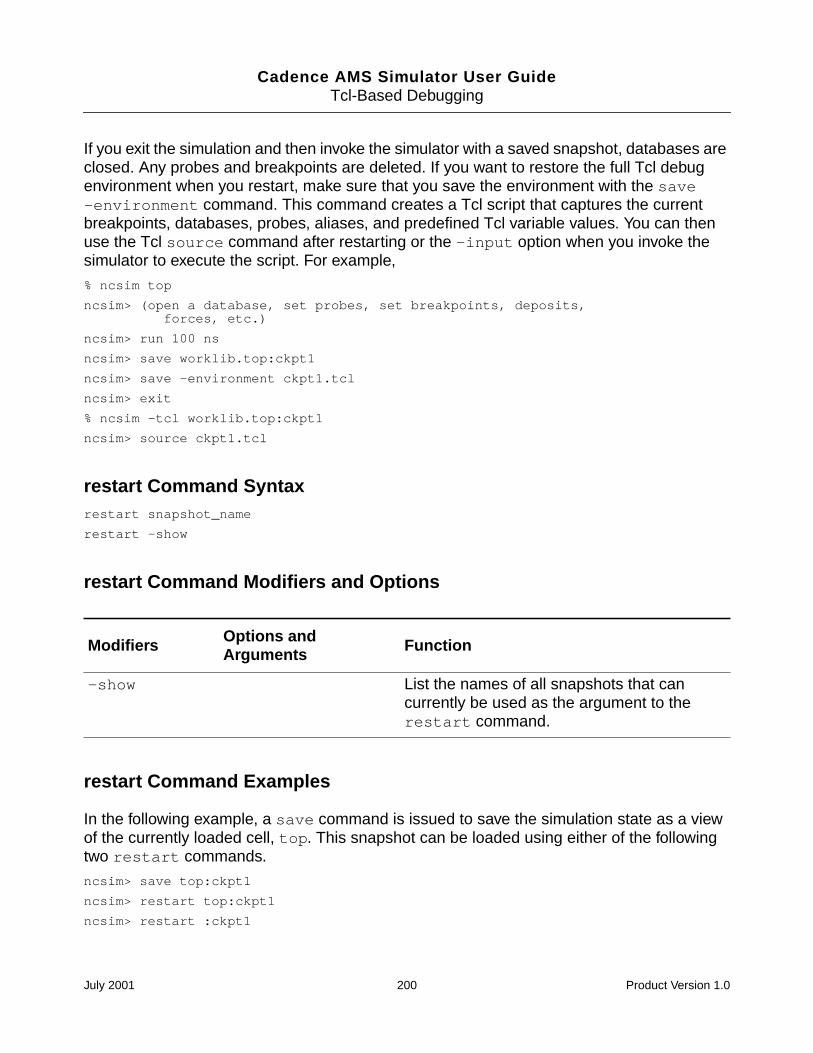
Cadence AMS Simulator User GuideTcl-Based Debugging
If you exit the simulation and then invoke the simulator with a saved snapshot, databases areclosed. Any probes and breakpoints are deleted. If you want to restore the full Tcl debugenvironment when you restart, make sure that you save the environment with the save-environment command. This command creates a Tcl script that captures the currentbreakpoints, databases, probes, aliases, and predefined Tcl variable values. You can thenuse the Tcl source command after restarting or the -input option when you invoke thesimulator to execute the script. For example,
% ncsim top
ncsim> (open a database, set probes, set breakpoints, deposits,forces, etc.)
ncsim> run 100 ns
ncsim> save worklib.top:ckpt1
ncsim> save -environment ckpt1.tcl
ncsim> exit
% ncsim -tcl worklib.top:ckpt1
ncsim> source ckpt1.tcl
restart Command Syntaxrestart snapshot_name
restart -show
restart Command Modifiers and Options
restart Command Examples
In the following example, a save command is issued to save the simulation state as a viewof the currently loaded cell, top. This snapshot can be loaded using either of the followingtwo restart commands.
ncsim> save top:ckpt1
ncsim> restart top:ckpt1
ncsim> restart :ckpt1
Modifiers Options andArguments Function
-show List the names of all snapshots that cancurrently be used as the argument to therestart command.
July 2001 200 Product Version 1.0
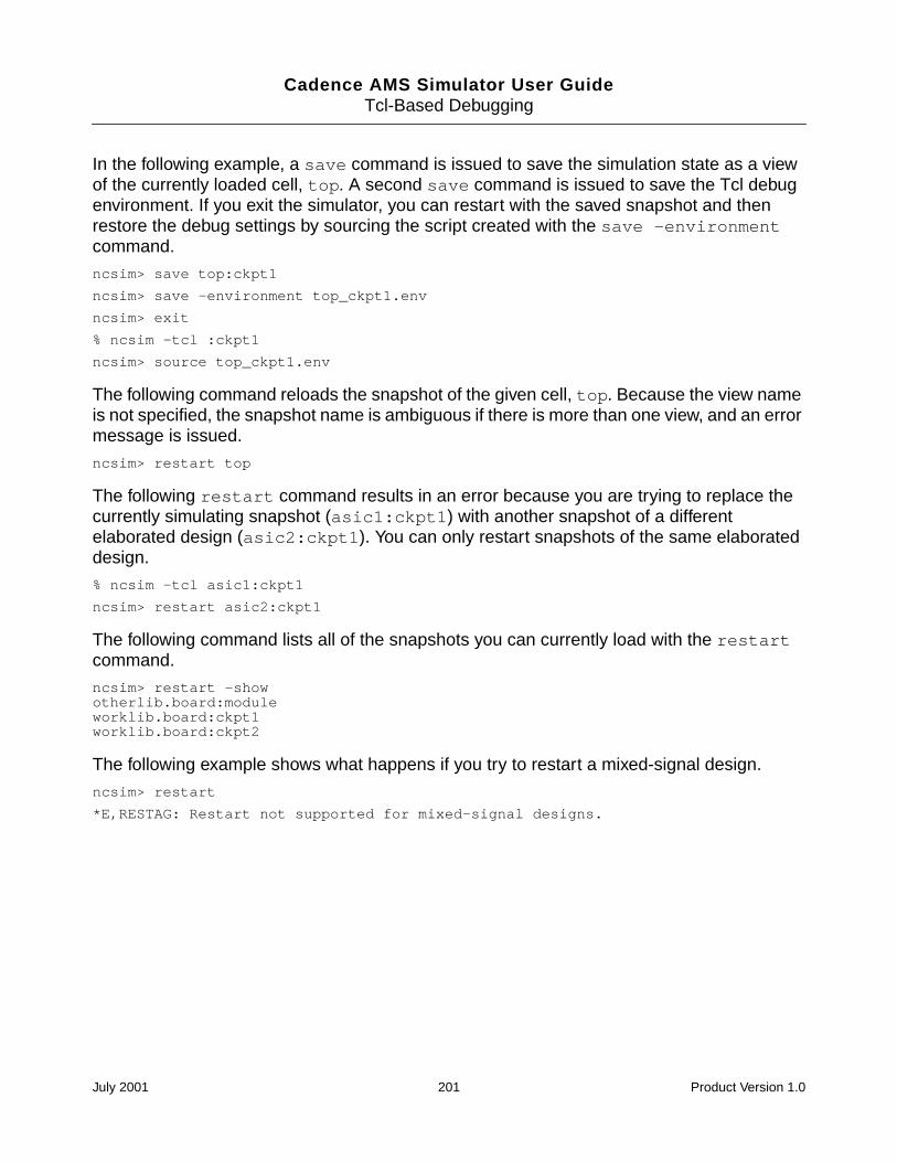
Cadence AMS Simulator User GuideTcl-Based Debugging
In the following example, a save command is issued to save the simulation state as a viewof the currently loaded cell, top. A second save command is issued to save the Tcl debugenvironment. If you exit the simulator, you can restart with the saved snapshot and thenrestore the debug settings by sourcing the script created with the save -environmentcommand.
ncsim> save top:ckpt1
ncsim> save -environment top_ckpt1.env
ncsim> exit
% ncsim -tcl :ckpt1
ncsim> source top_ckpt1.env
The following command reloads the snapshot of the given cell, top. Because the view nameis not specified, the snapshot name is ambiguous if there is more than one view, and an errormessage is issued.
ncsim> restart top
The following restart command results in an error because you are trying to replace thecurrently simulating snapshot (asic1:ckpt1) with another snapshot of a differentelaborated design (asic2:ckpt1). You can only restart snapshots of the same elaborateddesign.
% ncsim -tcl asic1:ckpt1
ncsim> restart asic2:ckpt1
The following command lists all of the snapshots you can currently load with the restartcommand.
ncsim> restart -showotherlib.board:moduleworklib.board:ckpt1worklib.board:ckpt2
The following example shows what happens if you try to restart a mixed-signal design.
ncsim> restart
*E,RESTAG: Restart not supported for mixed-signal designs.
July 2001 201 Product Version 1.0
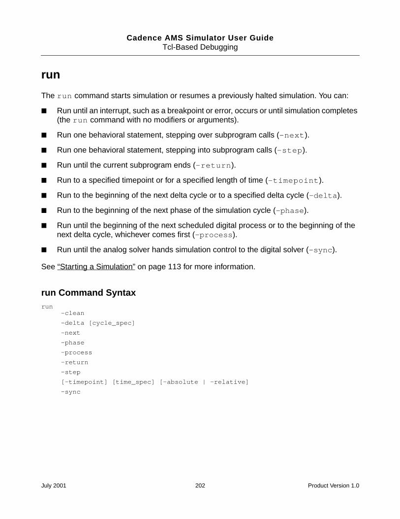
Cadence AMS Simulator User GuideTcl-Based Debugging
run
The run command starts simulation or resumes a previously halted simulation. You can:
Run until an interrupt, such as a breakpoint or error, occurs or until simulation completes(the run command with no modifiers or arguments).
Run one behavioral statement, stepping over subprogram calls (-next).
Run one behavioral statement, stepping into subprogram calls (-step).
Run until the current subprogram ends (-return).
Run to a specified timepoint or for a specified length of time (-timepoint).
Run to the beginning of the next delta cycle or to a specified delta cycle (-delta).
Run to the beginning of the next phase of the simulation cycle (-phase).
Run until the beginning of the next scheduled digital process or to the beginning of thenext delta cycle, whichever comes first (-process).
Run until the analog solver hands simulation control to the digital solver (-sync).
See “Starting a Simulation” on page 113 for more information.
run Command Syntaxrun
-clean
-delta [cycle_spec]
-next
-phase
-process
-return
-step
[-timepoint] [time_spec] [-absolute | -relative]
-sync
July 2001 202 Product Version 1.0
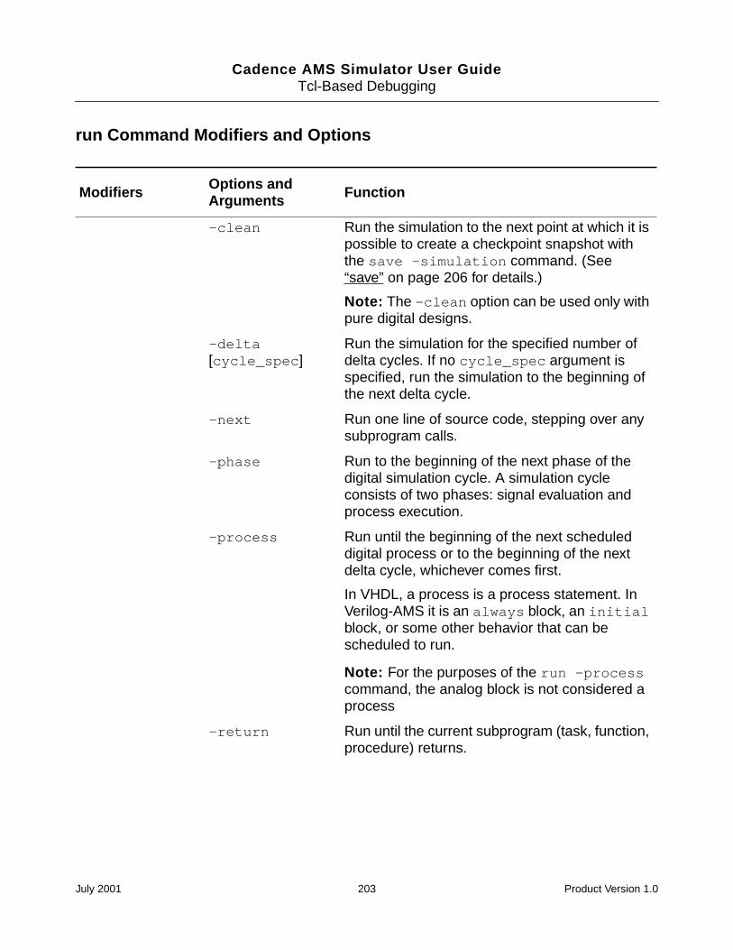
Cadence AMS Simulator User GuideTcl-Based Debugging
run Command Modifiers and Options
Modifiers Options andArguments Function
-clean Run the simulation to the next point at which it ispossible to create a checkpoint snapshot withthe save -simulation command. (See“save” on page 206 for details.)
Note: The -clean option can be used only withpure digital designs.
-delta[cycle_spec]
Run the simulation for the specified number ofdelta cycles. If no cycle_spec argument isspecified, run the simulation to the beginning ofthe next delta cycle.
-next Run one line of source code, stepping over anysubprogram calls.
-phase Run to the beginning of the next phase of thedigital simulation cycle. A simulation cycleconsists of two phases: signal evaluation andprocess execution.
-process Run until the beginning of the next scheduleddigital process or to the beginning of the nextdelta cycle, whichever comes first.
In VHDL, a process is a process statement. InVerilog-AMS it is an always block, an initialblock, or some other behavior that can bescheduled to run.
Note: For the purposes of the run -processcommand, the analog block is not considered aprocess
-return Run until the current subprogram (task, function,procedure) returns.
July 2001 203 Product Version 1.0
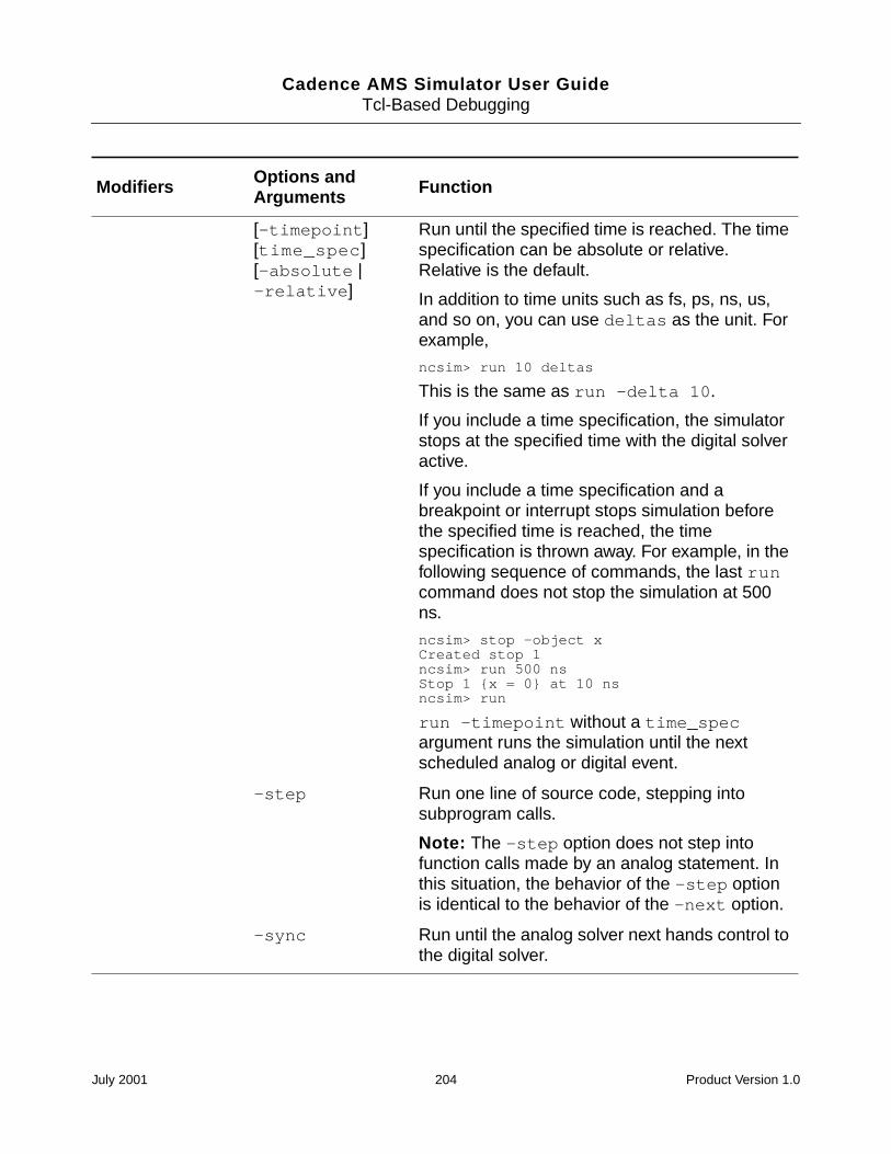
Cadence AMS Simulator User GuideTcl-Based Debugging
[-timepoint][time_spec][-absolute |-relative]
Run until the specified time is reached. The timespecification can be absolute or relative.Relative is the default.
In addition to time units such as fs, ps, ns, us,and so on, you can use deltas as the unit. Forexample,
ncsim> run 10 deltas
This is the same as run -delta 10.
If you include a time specification, the simulatorstops at the specified time with the digital solveractive.
If you include a time specification and abreakpoint or interrupt stops simulation beforethe specified time is reached, the timespecification is thrown away. For example, in thefollowing sequence of commands, the last runcommand does not stop the simulation at 500ns.
ncsim> stop -object xCreated stop 1ncsim> run 500 nsStop 1 x = 0 at 10 nsncsim> run
run -timepoint without a time_specargument runs the simulation until the nextscheduled analog or digital event.
-step Run one line of source code, stepping intosubprogram calls.
Note: The -step option does not step intofunction calls made by an analog statement. Inthis situation, the behavior of the -step optionis identical to the behavior of the -next option.
-sync Run until the analog solver next hands control tothe digital solver.
Modifiers Options andArguments Function
July 2001 204 Product Version 1.0
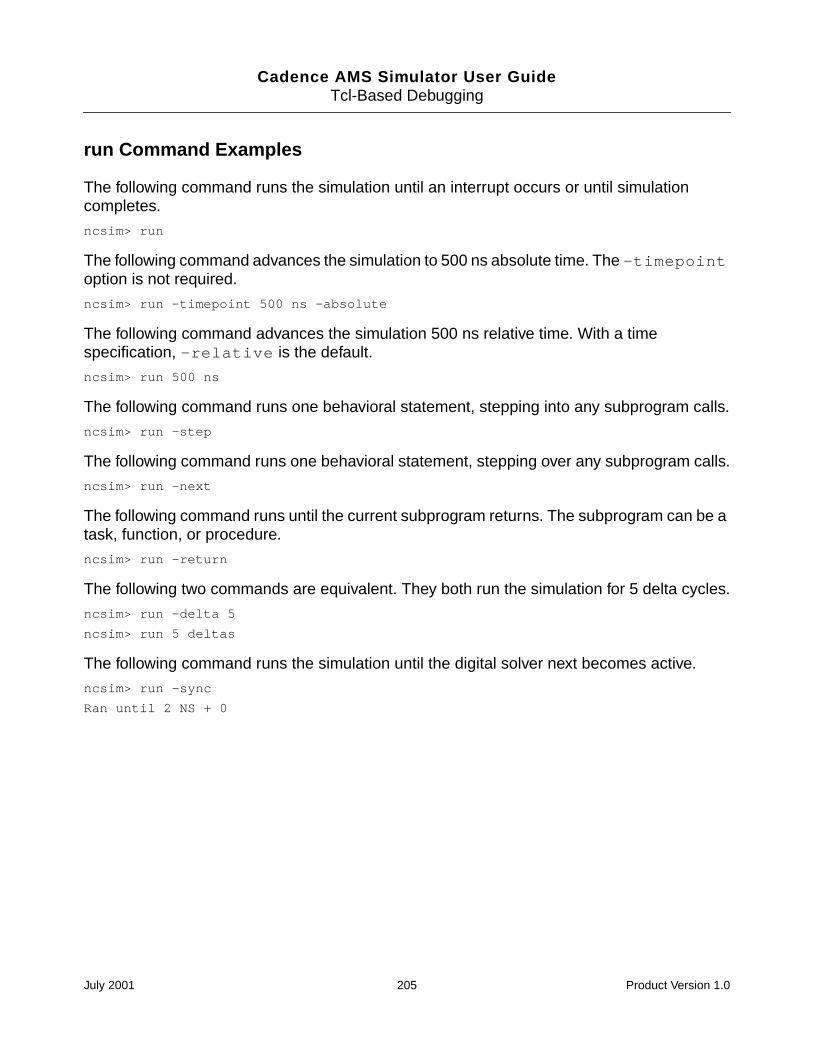
Cadence AMS Simulator User GuideTcl-Based Debugging
run Command Examples
The following command runs the simulation until an interrupt occurs or until simulationcompletes.
ncsim> run
The following command advances the simulation to 500 ns absolute time. The -timepointoption is not required.
ncsim> run -timepoint 500 ns -absolute
The following command advances the simulation 500 ns relative time. With a timespecification, -relative is the default.
ncsim> run 500 ns
The following command runs one behavioral statement, stepping into any subprogram calls.
ncsim> run -step
The following command runs one behavioral statement, stepping over any subprogram calls.
ncsim> run -next
The following command runs until the current subprogram returns. The subprogram can be atask, function, or procedure.
ncsim> run -return
The following two commands are equivalent. They both run the simulation for 5 delta cycles.
ncsim> run -delta 5
ncsim> run 5 deltas
The following command runs the simulation until the digital solver next becomes active.
ncsim> run -sync
Ran until 2 NS + 0
July 2001 205 Product Version 1.0
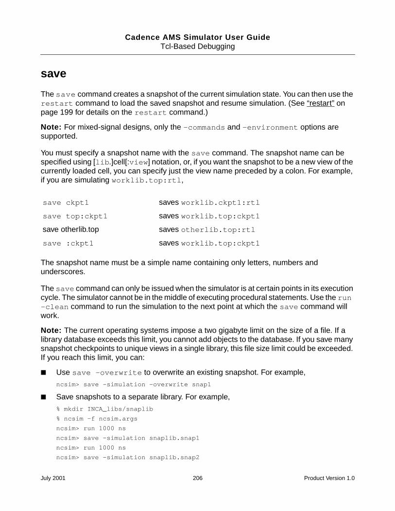
Cadence AMS Simulator User GuideTcl-Based Debugging
save
The save command creates a snapshot of the current simulation state. You can then use therestart command to load the saved snapshot and resume simulation. (See “restart” onpage 199 for details on the restart command.)
Note: For mixed-signal designs, only the -commands and -environment options aresupported.
You must specify a snapshot name with the save command. The snapshot name can bespecified using [lib.]cell[:view] notation, or, if you want the snapshot to be a new view of thecurrently loaded cell, you can specify just the view name preceded by a colon. For example,if you are simulating worklib.top:rtl,
The snapshot name must be a simple name containing only letters, numbers andunderscores.
The save command can only be issued when the simulator is at certain points in its executioncycle. The simulator cannot be in the middle of executing procedural statements. Use the run-clean command to run the simulation to the next point at which the save command willwork.
Note: The current operating systems impose a two gigabyte limit on the size of a file. If alibrary database exceeds this limit, you cannot add objects to the database. If you save manysnapshot checkpoints to unique views in a single library, this file size limit could be exceeded.If you reach this limit, you can:
Use save -overwrite to overwrite an existing snapshot. For example,
ncsim> save -simulation -overwrite snap1
Save snapshots to a separate library. For example,
% mkdir INCA_libs/snaplib
% ncsim -f ncsim.args
ncsim> run 1000 ns
ncsim> save -simulation snaplib.snap1
ncsim> run 1000 ns
ncsim> save -simulation snaplib.snap2
save ckpt1 saves worklib.ckpt1:rtl
save top:ckpt1 saves worklib.top:ckpt1
save otherlib.top saves otherlib.top:rtl
save :ckpt1 saves worklib.top:ckpt1
July 2001 206 Product Version 1.0
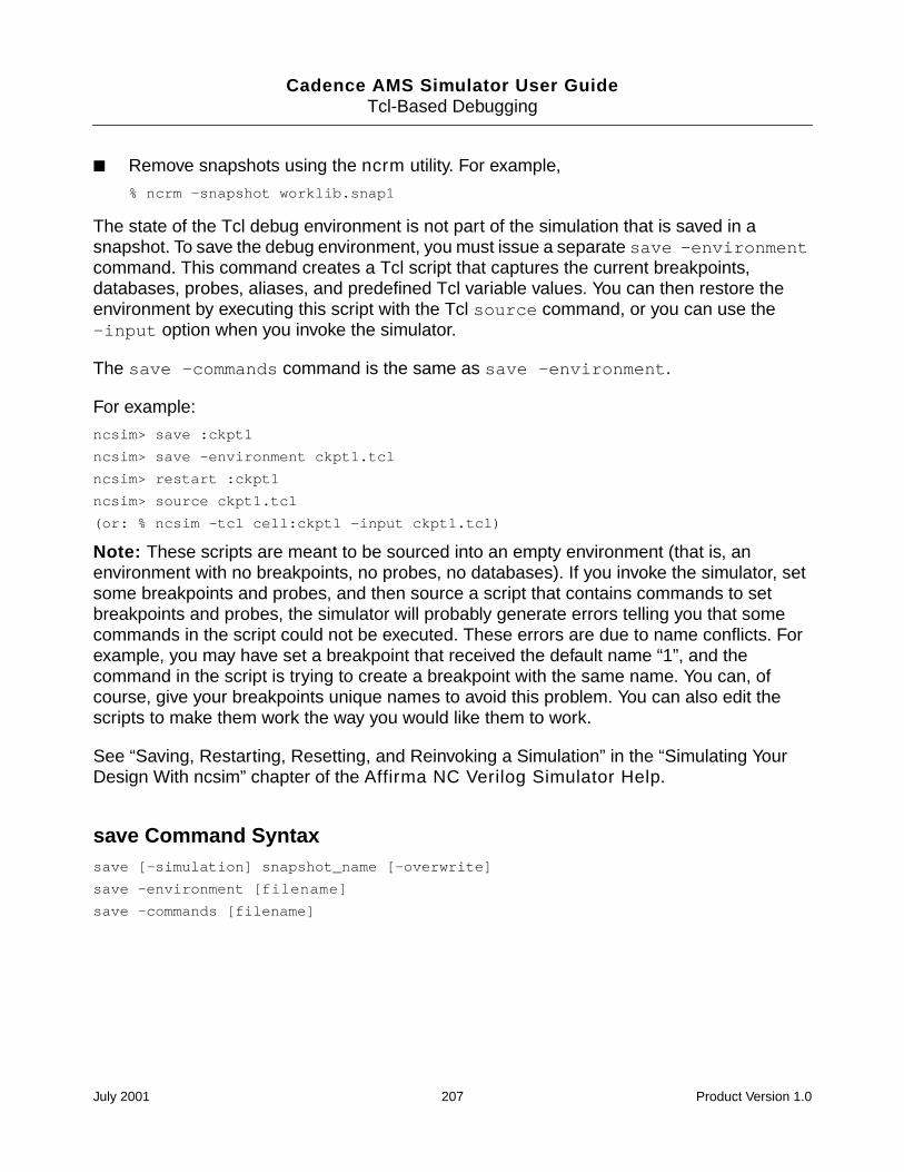
Cadence AMS Simulator User GuideTcl-Based Debugging
Remove snapshots using the ncrm utility. For example,
% ncrm -snapshot worklib.snap1
The state of the Tcl debug environment is not part of the simulation that is saved in asnapshot. To save the debug environment, you must issue a separate save -environmentcommand. This command creates a Tcl script that captures the current breakpoints,databases, probes, aliases, and predefined Tcl variable values. You can then restore theenvironment by executing this script with the Tcl source command, or you can use the-input option when you invoke the simulator.
The save -commands command is the same as save -environment.
For example:
ncsim> save :ckpt1
ncsim> save -environment ckpt1.tcl
ncsim> restart :ckpt1
ncsim> source ckpt1.tcl
(or: % ncsim -tcl cell:ckpt1 -input ckpt1.tcl)
Note: These scripts are meant to be sourced into an empty environment (that is, anenvironment with no breakpoints, no probes, no databases). If you invoke the simulator, setsome breakpoints and probes, and then source a script that contains commands to setbreakpoints and probes, the simulator will probably generate errors telling you that somecommands in the script could not be executed. These errors are due to name conflicts. Forexample, you may have set a breakpoint that received the default name “1”, and thecommand in the script is trying to create a breakpoint with the same name. You can, ofcourse, give your breakpoints unique names to avoid this problem. You can also edit thescripts to make them work the way you would like them to work.
See “Saving, Restarting, Resetting, and Reinvoking a Simulation” in the “Simulating YourDesign With ncsim” chapter of the Affirma NC Verilog Simulator Help.
save Command Syntaxsave [-simulation] snapshot_name [-overwrite]
save -environment [filename]
save -commands [filename]
July 2001 207 Product Version 1.0
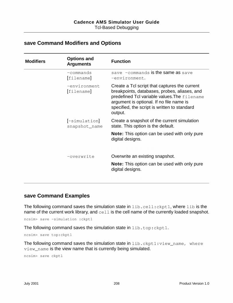
Cadence AMS Simulator User GuideTcl-Based Debugging
save Command Modifiers and Options
save Command Examples
The following command saves the simulation state in lib.cell:ckpt1, where lib is thename of the current work library, and cell is the cell name of the currently loaded snapshot.
ncsim> save -simulation :ckpt1
The following command saves the simulation state in lib.top:ckpt1.
ncsim> save top:ckpt1
The following command saves the simulation state in lib.ckpt1:view_name, whereview_name is the view name that is currently being simulated.
ncsim> save ckpt1
Modifiers Options andArguments Function
-commands[filename]
save -commands is the same as save-environment.
-environment[filename]
Create a Tcl script that captures the currentbreakpoints, databases, probes, aliases, andpredefined Tcl variable values.The filenameargument is optional. If no file name isspecified, the script is written to standardoutput.
[-simulation]snapshot_name
Create a snapshot of the current simulationstate. This option is the default.
Note: This option can be used with only puredigital designs.
Is the note still valid???
-overwrite Overwrite an existing snapshot.
Note: This option can be used with only puredigital designs.
Is the note still valid???
July 2001 208 Product Version 1.0
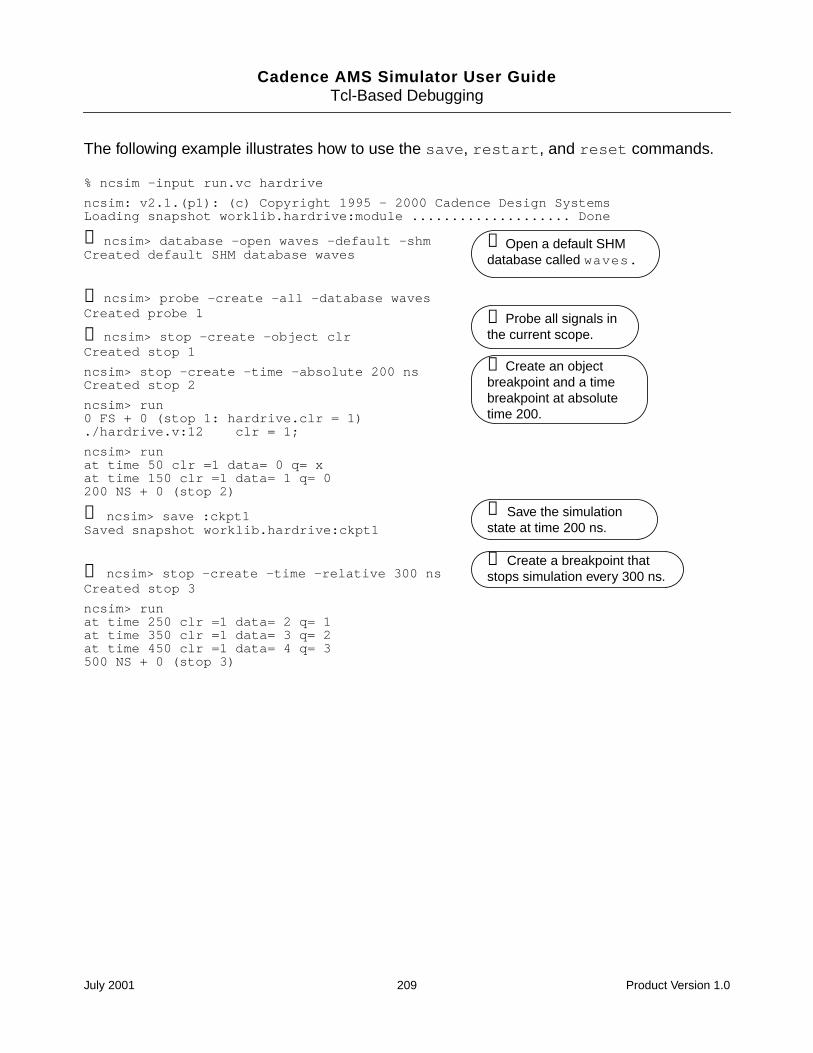
Cadence AMS Simulator User GuideTcl-Based Debugging
The following example illustrates how to use the save, restart, and reset commands.
% ncsim -input run.vc hardrive
ncsim: v2.1.(p1): (c) Copyright 1995 - 2000 Cadence Design SystemsLoading snapshot worklib.hardrive:module .................... Done
➊ ncsim> database -open waves -default -shmCreated default SHM database waves
➋ ncsim> probe -create -all -database wavesCreated probe 1
➌ ncsim> stop -create -object clrCreated stop 1
ncsim> stop -create -time -absolute 200 nsCreated stop 2
ncsim> run0 FS + 0 (stop 1: hardrive.clr = 1)./hardrive.v:12 clr = 1;
ncsim> runat time 50 clr =1 data= 0 q= xat time 150 clr =1 data= 1 q= 0200 NS + 0 (stop 2)
➍ ncsim> save :ckpt1Saved snapshot worklib.hardrive:ckpt1
➎ ncsim> stop -create -time -relative 300 nsCreated stop 3
ncsim> runat time 250 clr =1 data= 2 q= 1at time 350 clr =1 data= 3 q= 2at time 450 clr =1 data= 4 q= 3500 NS + 0 (stop 3)
➊ Open a default SHMdatabase called waves.
➋ Probe all signals inthe current scope.
➌ Create an objectbreakpoint and a timebreakpoint at absolutetime 200.
➍ Save the simulationstate at time 200 ns.
➎ Create a breakpoint thatstops simulation every 300 ns.
July 2001 209 Product Version 1.0
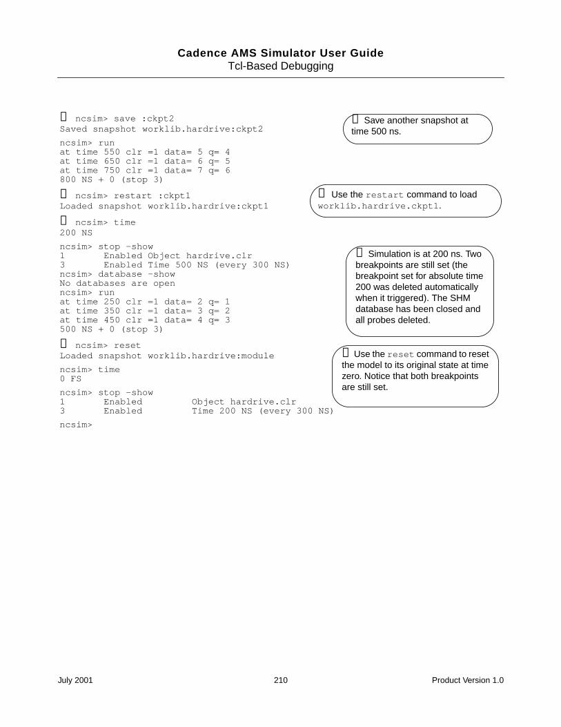
Cadence AMS Simulator User GuideTcl-Based Debugging
➏ ncsim> save :ckpt2Saved snapshot worklib.hardrive:ckpt2
ncsim> runat time 550 clr =1 data= 5 q= 4at time 650 clr =1 data= 6 q= 5at time 750 clr =1 data= 7 q= 6800 NS + 0 (stop 3)
➐ ncsim> restart :ckpt1Loaded snapshot worklib.hardrive:ckpt1
➑ ncsim> time200 NS
ncsim> stop -show1 Enabled Object hardrive.clr3 Enabled Time 500 NS (every 300 NS)ncsim> database -showNo databases are openncsim> runat time 250 clr =1 data= 2 q= 1at time 350 clr =1 data= 3 q= 2at time 450 clr =1 data= 4 q= 3500 NS + 0 (stop 3)
➒ ncsim> resetLoaded snapshot worklib.hardrive:module
ncsim> time0 FS
ncsim> stop -show1 Enabled Object hardrive.clr3 Enabled Time 200 NS (every 300 NS)
ncsim>
➐ Use the restart command to loadworklib.hardrive.ckpt1.
➏ Save another snapshot attime 500 ns.
➒ Use the reset command to resetthe model to its original state at timezero. Notice that both breakpointsare still set.
➑ Simulation is at 200 ns. Twobreakpoints are still set (thebreakpoint set for absolute time200 was deleted automaticallywhen it triggered). The SHMdatabase has been closed andall probes deleted.
July 2001 210 Product Version 1.0
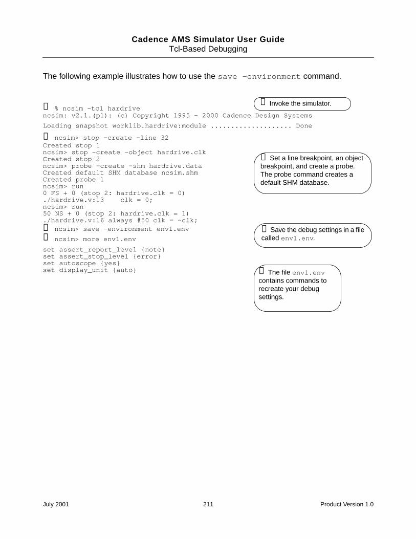
Cadence AMS Simulator User GuideTcl-Based Debugging
The following example illustrates how to use the save -environment command.
➊ % ncsim -tcl hardrivencsim: v2.1.(p1): (c) Copyright 1995 - 2000 Cadence Design Systems
Loading snapshot worklib.hardrive:module .................... Done
➋ ncsim> stop -create -line 32Created stop 1ncsim> stop -create -object hardrive.clkCreated stop 2ncsim> probe -create -shm hardrive.dataCreated default SHM database ncsim.shmCreated probe 1ncsim> run0 FS + 0 (stop 2: hardrive.clk = 0)./hardrive.v:13 clk = 0;ncsim> run50 NS + 0 (stop 2: hardrive.clk = 1)./hardrive.v:16 always #50 clk = ~clk;➌ ncsim> save -environment env1.env
➍ ncsim> more env1.env
set assert_report_level noteset assert_stop_level errorset autoscope yesset display_unit auto
➊ Invoke the simulator.
➋ Set a line breakpoint, an objectbreakpoint, and create a probe.The probe command creates adefault SHM database.
➌ Save the debug settings in a filecalled env1.env.
➍ The file env1.envcontains commands torecreate your debugsettings.
July 2001 211 Product Version 1.0
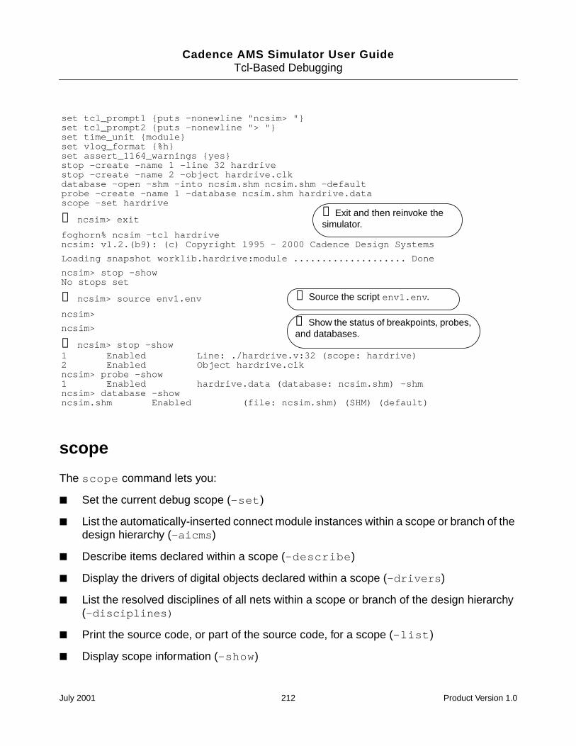
Cadence AMS Simulator User GuideTcl-Based Debugging
scope
The scope command lets you:
Set the current debug scope (-set)
List the automatically-inserted connect module instances within a scope or branch of thedesign hierarchy (-aicms)
Describe items declared within a scope (-describe)
Display the drivers of digital objects declared within a scope (-drivers)
List the resolved disciplines of all nets within a scope or branch of the design hierarchy(-disciplines)
Print the source code, or part of the source code, for a scope (-list)
Display scope information (-show)
set tcl_prompt1 puts -nonewline "ncsim> "set tcl_prompt2 puts -nonewline "> "set time_unit moduleset vlog_format %hset assert_1164_warnings yesstop -create -name 1 -line 32 hardrivestop -create -name 2 -object hardrive.clkdatabase -open -shm -into ncsim.shm ncsim.shm -defaultprobe -create -name 1 -database ncsim.shm hardrive.datascope -set hardrive
➎ ncsim> exit
foghorn% ncsim -tcl hardrivencsim: v1.2.(b9): (c) Copyright 1995 - 2000 Cadence Design Systems
Loading snapshot worklib.hardrive:module .................... Done
ncsim> stop -showNo stops set
➏ ncsim> source env1.env
ncsim>
ncsim>
➐ ncsim> stop -show1 Enabled Line: ./hardrive.v:32 (scope: hardrive)2 Enabled Object hardrive.clkncsim> probe -show1 Enabled hardrive.data (database: ncsim.shm) -shmncsim> database -showncsim.shm Enabled (file: ncsim.shm) (SHM) (default)
➎ Exit and then reinvoke thesimulator.
➐ Show the status of breakpoints, probes,and databases.
➏ Source the script env1.env.
July 2001 212 Product Version 1.0
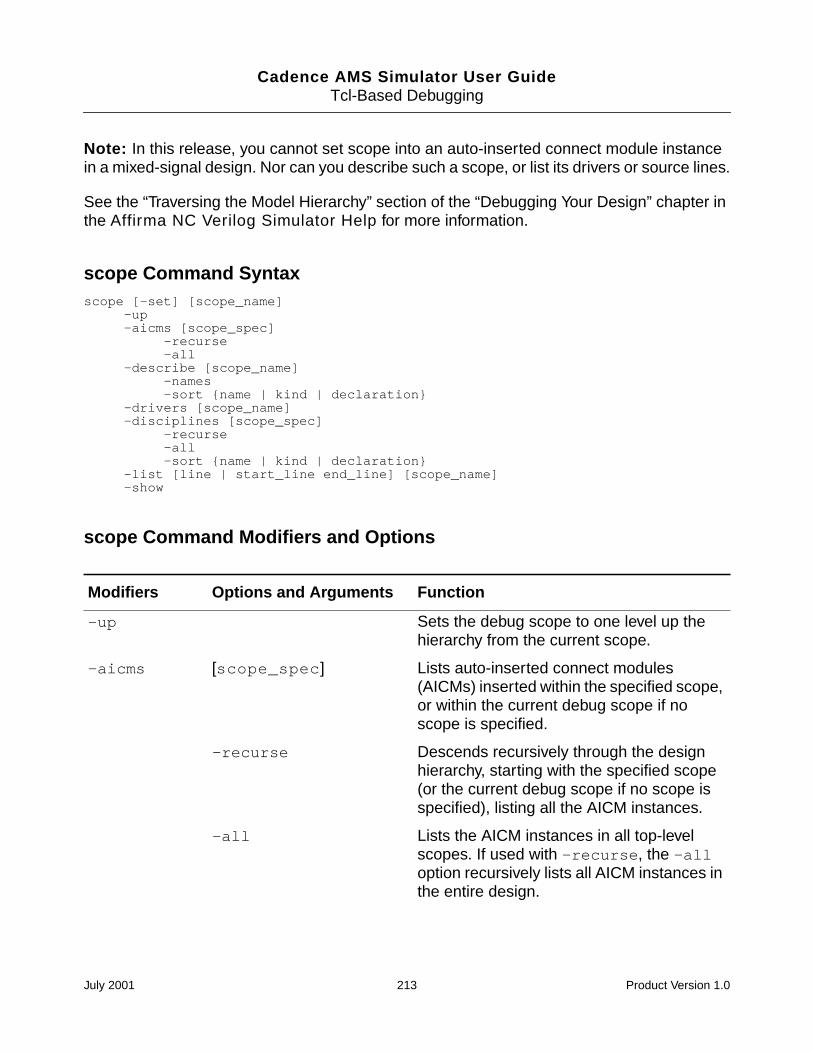
Cadence AMS Simulator User GuideTcl-Based Debugging
Note: In this release, you cannot set scope into an auto-inserted connect module instancein a mixed-signal design. Nor can you describe such a scope, or list its drivers or source lines.
See the “Traversing the Model Hierarchy” section of the “Debugging Your Design” chapter inthe Affirma NC Verilog Simulator Help for more information.
scope Command Syntaxscope [-set] [scope_name]
-up-aicms [scope_spec]
-recurse-all
-describe [scope_name]-names-sort name | kind | declaration
-drivers [scope_name]-disciplines [scope_spec]
-recurse-all-sort name | kind | declaration
-list [line | start_line end_line] [scope_name]-show
scope Command Modifiers and Options
Modifiers Options and Arguments Function
-up Sets the debug scope to one level up thehierarchy from the current scope.
-aicms [scope_spec] Lists auto-inserted connect modules(AICMs) inserted within the specified scope,or within the current debug scope if noscope is specified.
-recurse Descends recursively through the designhierarchy, starting with the specified scope(or the current debug scope if no scope isspecified), listing all the AICM instances.
-all Lists the AICM instances in all top-levelscopes. If used with -recurse, the -alloption recursively lists all AICM instances inthe entire design.
July 2001 213 Product Version 1.0
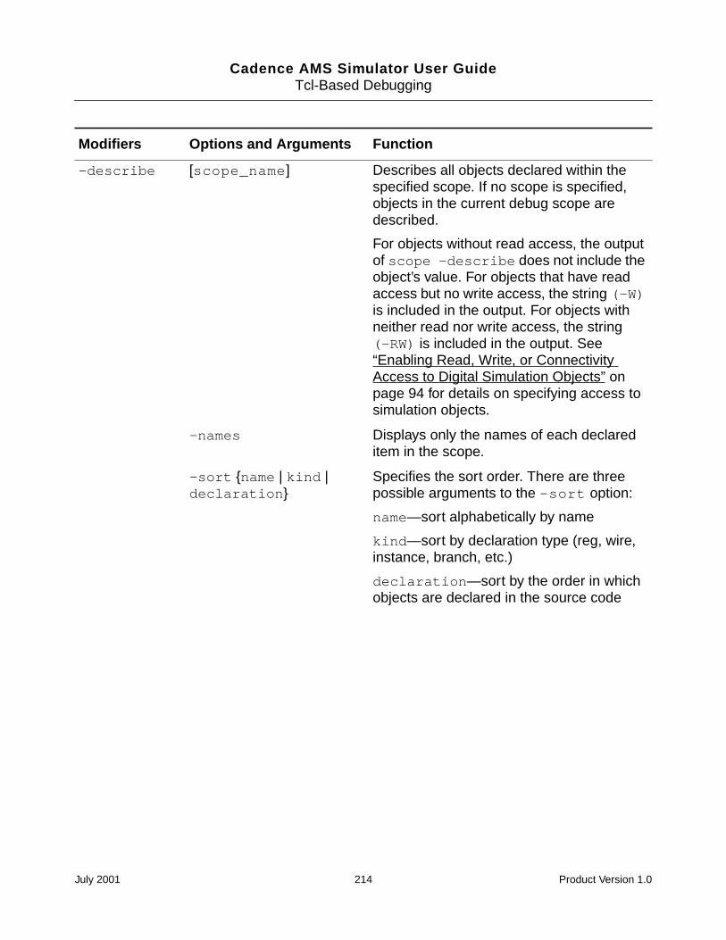
Cadence AMS Simulator User GuideTcl-Based Debugging
-describe [scope_name] Describes all objects declared within thespecified scope. If no scope is specified,objects in the current debug scope aredescribed.
For objects without read access, the outputof scope -describe does not include theobject’s value. For objects that have readaccess but no write access, the string (-W)is included in the output. For objects withneither read nor write access, the string(-RW) is included in the output. See“Enabling Read, Write, or ConnectivityAccess to Digital Simulation Objects” onpage 94 for details on specifying access tosimulation objects.
-names Displays only the names of each declareditem in the scope.
-sort name | kind |declaration
Specifies the sort order. There are threepossible arguments to the -sort option:
name—sort alphabetically by name
kind—sort by declaration type (reg, wire,instance, branch, etc.)
declaration—sort by the order in whichobjects are declared in the source code
Modifiers Options and Arguments Function
July 2001 214 Product Version 1.0
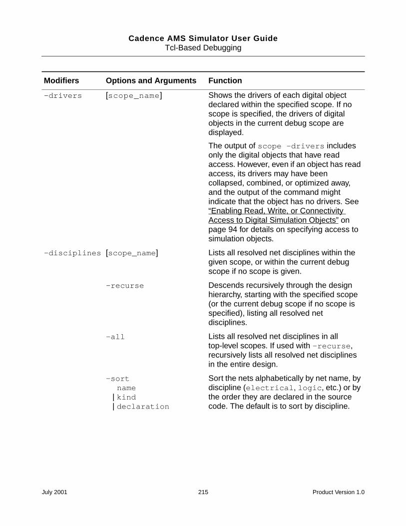
Cadence AMS Simulator User GuideTcl-Based Debugging
-drivers [scope_name] Shows the drivers of each digital objectdeclared within the specified scope. If noscope is specified, the drivers of digitalobjects in the current debug scope aredisplayed.
The output of scope -drivers includesonly the digital objects that have readaccess. However, even if an object has readaccess, its drivers may have beencollapsed, combined, or optimized away,and the output of the command mightindicate that the object has no drivers. See“Enabling Read, Write, or ConnectivityAccess to Digital Simulation Objects” onpage 94 for details on specifying access tosimulation objects.
-disciplines [scope_name] Lists all resolved net disciplines within thegiven scope, or within the current debugscope if no scope is given.
-recurse Descends recursively through the designhierarchy, starting with the specified scope(or the current debug scope if no scope isspecified), listing all resolved netdisciplines.
-all Lists all resolved net disciplines in alltop-level scopes. If used with -recurse,recursively lists all resolved net disciplinesin the entire design.
-sortname
| kind| declaration
Sort the nets alphabetically by net name, bydiscipline (electrical, logic, etc.) or bythe order they are declared in the sourcecode. The default is to sort by discipline.
Modifiers Options and Arguments Function
July 2001 215 Product Version 1.0
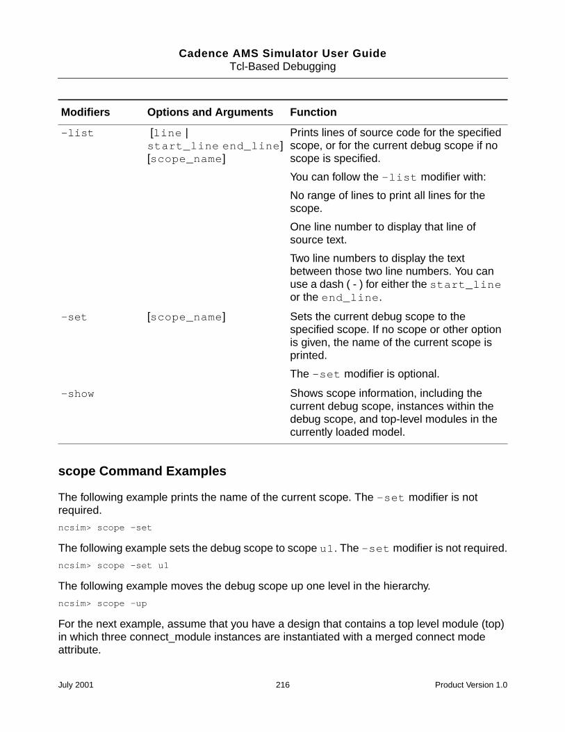
Cadence AMS Simulator User GuideTcl-Based Debugging
scope Command Examples
The following example prints the name of the current scope. The -set modifier is notrequired.
ncsim> scope -set
The following example sets the debug scope to scope u1. The -set modifier is not required.
ncsim> scope -set u1
The following example moves the debug scope up one level in the hierarchy.
ncsim> scope -up
For the next example, assume that you have a design that contains a top level module (top)in which three connect_module instances are instantiated with a merged connect modeattribute.
-list [line |start_line end_line][scope_name]
Prints lines of source code for the specifiedscope, or for the current debug scope if noscope is specified.
You can follow the -list modifier with:
No range of lines to print all lines for thescope.
One line number to display that line ofsource text.
Two line numbers to display the textbetween those two line numbers. You canuse a dash ( - ) for either the start_lineor the end_line.
-set [scope_name] Sets the current debug scope to thespecified scope. If no scope or other optionis given, the name of the current scope isprinted.
The -set modifier is optional.
-show Shows scope information, including thecurrent debug scope, instances within thedebug scope, and top-level modules in thecurrently loaded model.
Modifiers Options and Arguments Function
July 2001 216 Product Version 1.0
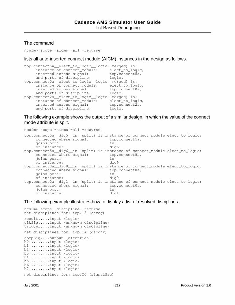
Cadence AMS Simulator User GuideTcl-Based Debugging
The command
ncsim> scope -aicms -all -recurse
lists all auto-inserted connect module (AICM) instances in the design as follows.
top.connect5a__elect_to_logic__logic (merged) is:instance of connect_module: elect_to_logic,inserted across signal: top.connect5a,and ports of discipline: logic.
top.connect0a__elect_to_logic__logic (merged) is:instance of connect_module: elect_to_logic,inserted across signal: top.connect0a,and ports of discipline: logic.
top.connect2a__elect_to_logic__logic (merged) is:instance of connect_module: elect_to_logic,inserted across signal: top.connect2a,and ports of discipline: logic.
The following example shows the output of a similar design, in which the value of the connectmode attribute is split.
ncsim> scope -aicms -all -recurse
top.connect5a__dig5__in (split) is instance of connect_module elect_to_logic:connected where signal: top.connect5a,joins port: in,of instance: dig5.
top.connect5a__dig6__in (split) is instance of connect_module elect_to_logic:connected where signal: top.connect5a,joins port: in,of instance: dig6.
top.connect0a__dig0__in (split) is instance of connect_module elect_to_logic:connected where signal: top.connect0a,joins port: in,of instance: dig0.
top.connect0a__dig1__in (split) is instance of connect_module elect_to_logic:connected where signal: top.connect0a,joins port: in,of instance: dig1.
The following example illustrates how to display a list of resolved disciplines.
ncsim> scope -discipline -recursenet disciplines for: top.I3 (sareg)
result.....input (logic)clkSig.....input (unknown discipline)trigger....input (unknown discipline)
net disciplines for: top.I4 (daconv)
compSig....output (electrical)b0.........input (logic)b1.........input (logic)b2.........input (logic)b3.........input (logic)b4.........input (logic)b5.........input (logic)b6.........input (logic)b7.........input (logic)
net disciplines for: top.I0 (signalSrc)
July 2001 217 Product Version 1.0
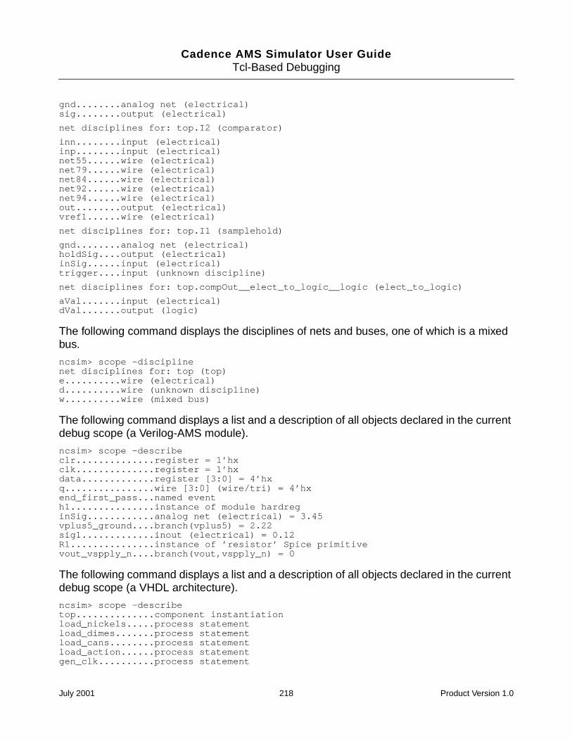
Cadence AMS Simulator User GuideTcl-Based Debugging
gnd........analog net (electrical)sig........output (electrical)
net disciplines for: top.I2 (comparator)
inn........input (electrical)inp........input (electrical)net55......wire (electrical)net79......wire (electrical)net84......wire (electrical)net92......wire (electrical)net94......wire (electrical)out........output (electrical)vref1......wire (electrical)
net disciplines for: top.I1 (samplehold)
gnd........analog net (electrical)holdSig....output (electrical)inSig......input (electrical)trigger....input (unknown discipline)
net disciplines for: top.compOut__elect_to_logic__logic (elect_to_logic)
aVal.......input (electrical)dVal.......output (logic)
The following command displays the disciplines of nets and buses, one of which is a mixedbus.
ncsim> scope -disciplinenet disciplines for: top (top)e..........wire (electrical)d..........wire (unknown discipline)w..........wire (mixed bus)
The following command displays a list and a description of all objects declared in the currentdebug scope (a Verilog-AMS module).
ncsim> scope -describeclr..............register = 1’hxclk..............register = 1’hxdata.............register [3:0] = 4’hxq................wire [3:0] (wire/tri) = 4’hxend_first_pass...named eventh1...............instance of module hardreginSig............analog net (electrical) = 3.45vplus5_ground....branch(vplus5) = 2.22sig1.............inout (electrical) = 0.12R1...............instance of ’resistor’ Spice primitivevout_vspply_n....branch(vout,vspply_n) = 0
The following command displays a list and a description of all objects declared in the currentdebug scope (a VHDL architecture).
ncsim> scope -describetop..............component instantiationload_nickels.....process statementload_dimes.......process statementload_cans........process statementload_action......process statementgen_clk..........process statement
July 2001 218 Product Version 1.0
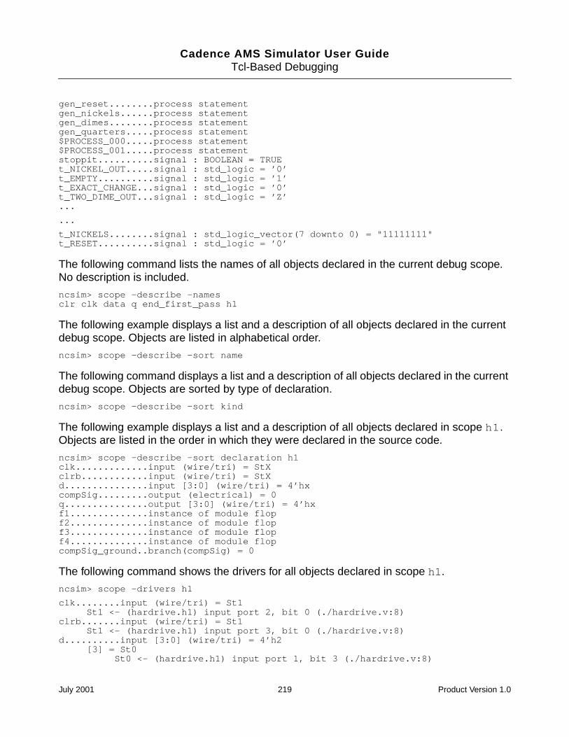
Cadence AMS Simulator User GuideTcl-Based Debugging
gen_reset........process statementgen_nickels......process statementgen_dimes........process statementgen_quarters.....process statement$PROCESS_000.....process statement$PROCESS_001.....process statementstoppit..........signal : BOOLEAN = TRUEt_NICKEL_OUT.....signal : std_logic = ’0’t_EMPTY..........signal : std_logic = ’1’t_EXACT_CHANGE...signal : std_logic = ’0’t_TWO_DIME_OUT...signal : std_logic = ’Z’...
...
t_NICKELS........signal : std_logic_vector(7 downto 0) = "11111111"t_RESET..........signal : std_logic = ’0’
The following command lists the names of all objects declared in the current debug scope.No description is included.
ncsim> scope -describe -namesclr clk data q end_first_pass h1
The following example displays a list and a description of all objects declared in the currentdebug scope. Objects are listed in alphabetical order.
ncsim> scope -describe -sort name
The following command displays a list and a description of all objects declared in the currentdebug scope. Objects are sorted by type of declaration.
ncsim> scope -describe -sort kind
The following example displays a list and a description of all objects declared in scope h1.Objects are listed in the order in which they were declared in the source code.
ncsim> scope -describe -sort declaration h1clk.............input (wire/tri) = StXclrb............input (wire/tri) = StXd...............input [3:0] (wire/tri) = 4’hxcompSig.........output (electrical) = 0q...............output [3:0] (wire/tri) = 4’hxf1..............instance of module flopf2..............instance of module flopf3..............instance of module flopf4..............instance of module flopcompSig_ground..branch(compSig) = 0
The following command shows the drivers for all objects declared in scope h1.
ncsim> scope -drivers h1
clk........input (wire/tri) = St1St1 <- (hardrive.h1) input port 2, bit 0 (./hardrive.v:8)
clrb.......input (wire/tri) = St1St1 <- (hardrive.h1) input port 3, bit 0 (./hardrive.v:8)
d..........input [3:0] (wire/tri) = 4’h2[3] = St0
St0 <- (hardrive.h1) input port 1, bit 3 (./hardrive.v:8)
July 2001 219 Product Version 1.0
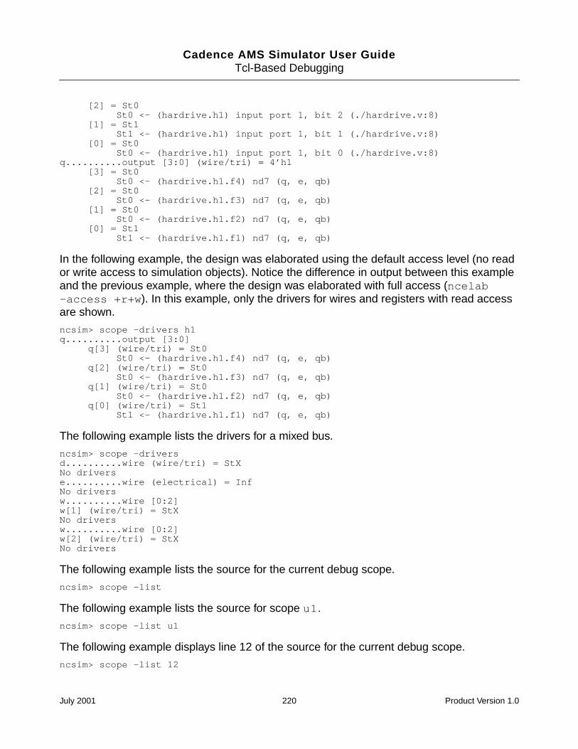
Cadence AMS Simulator User GuideTcl-Based Debugging
[2] = St0St0 <- (hardrive.h1) input port 1, bit 2 (./hardrive.v:8)
[1] = St1St1 <- (hardrive.h1) input port 1, bit 1 (./hardrive.v:8)
[0] = St0St0 <- (hardrive.h1) input port 1, bit 0 (./hardrive.v:8)
q..........output [3:0] (wire/tri) = 4’h1[3] = St0
St0 <- (hardrive.h1.f4) nd7 (q, e, qb)[2] = St0
St0 <- (hardrive.h1.f3) nd7 (q, e, qb)[1] = St0
St0 <- (hardrive.h1.f2) nd7 (q, e, qb)[0] = St1
St1 <- (hardrive.h1.f1) nd7 (q, e, qb)
In the following example, the design was elaborated using the default access level (no reador write access to simulation objects). Notice the difference in output between this exampleand the previous example, where the design was elaborated with full access (ncelab-access +r+w). In this example, only the drivers for wires and registers with read accessare shown.
ncsim> scope -drivers h1q..........output [3:0]
q[3] (wire/tri) = St0St0 <- (hardrive.h1.f4) nd7 (q, e, qb)
q[2] (wire/tri) = St0St0 <- (hardrive.h1.f3) nd7 (q, e, qb)
q[1] (wire/tri) = St0St0 <- (hardrive.h1.f2) nd7 (q, e, qb)
q[0] (wire/tri) = St1St1 <- (hardrive.h1.f1) nd7 (q, e, qb)
The following example lists the drivers for a mixed bus.
ncsim> scope -driversd..........wire (wire/tri) = StXNo driverse..........wire (electrical) = InfNo driversw..........wire [0:2]w[1] (wire/tri) = StXNo driversw..........wire [0:2]w[2] (wire/tri) = StXNo drivers
The following example lists the source for the current debug scope.
ncsim> scope -list
The following example lists the source for scope u1.
ncsim> scope -list u1
The following example displays line 12 of the source for the current debug scope.
ncsim> scope -list 12
July 2001 220 Product Version 1.0
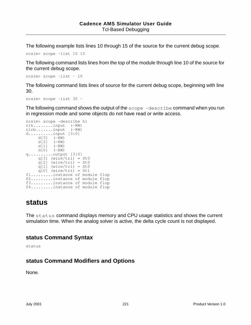
Cadence AMS Simulator User GuideTcl-Based Debugging
The following example lists lines 10 through 15 of the source for the current debug scope.
ncsim> scope -list 10 15
The following command lists lines from the top of the module through line 10 of the source forthe current debug scope.
ncsim> scope -list - 10
The following command lists lines of source for the current debug scope, beginning with line30.
ncsim> scope -list 30 -
The following command shows the output of the scope -describe command when you runin regression mode and some objects do not have read or write access.
ncsim> scope -describe h1clk........input (-RW)clrb.......input (-RW)d..........input [3:0]
d[3] (-RW)d[2] (-RW)d[1] (-RW)d[0] (-RW)
q..........output [3:0]q[3] (wire/tri) = St0q[2] (wire/tri) = St0q[1] (wire/tri) = St0q[0] (wire/tri) = St1
f1.........instance of module flopf2.........instance of module flopf3.........instance of module flopf4.........instance of module flop
status
The status command displays memory and CPU usage statistics and shows the currentsimulation time. When the analog solver is active, the delta cycle count is not displayed.
status Command Syntaxstatus
status Command Modifiers and Options
None.
July 2001 221 Product Version 1.0
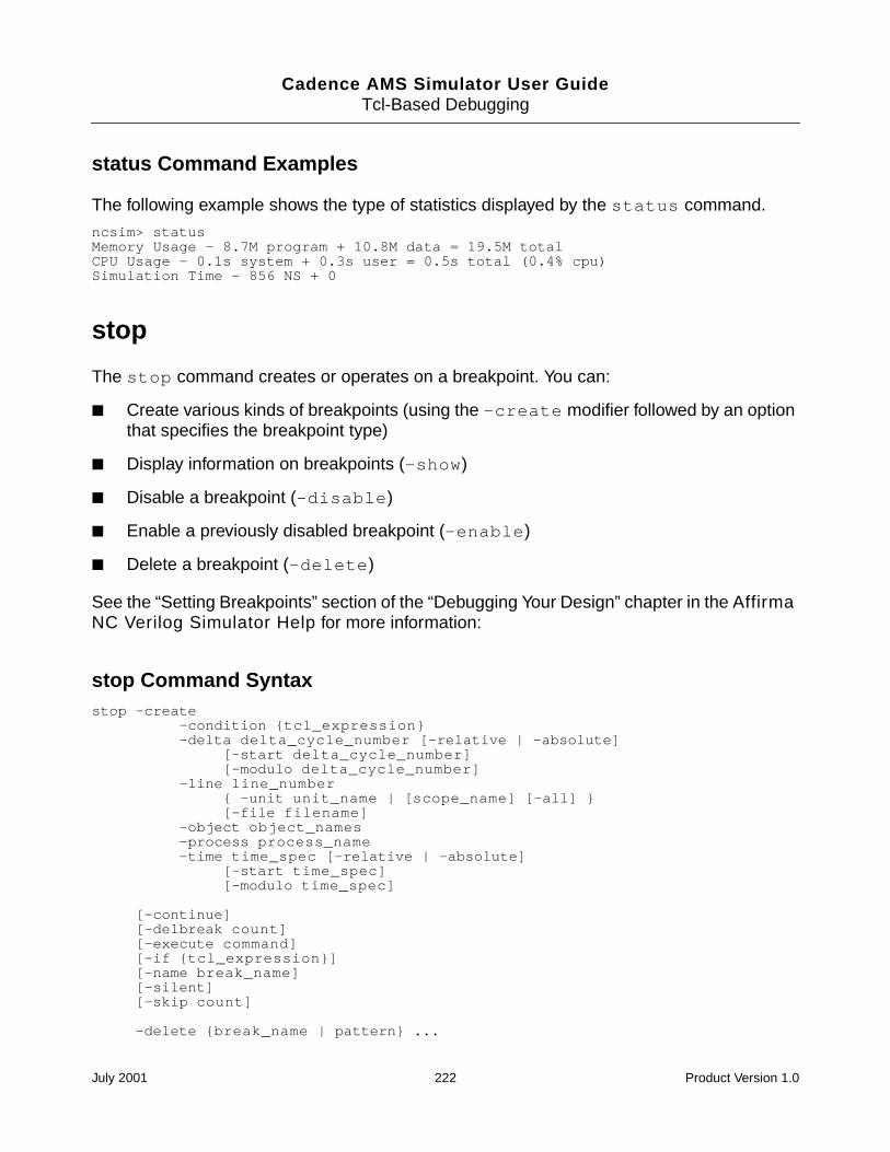
Cadence AMS Simulator User GuideTcl-Based Debugging
status Command Examples
The following example shows the type of statistics displayed by the status command.
ncsim> statusMemory Usage - 8.7M program + 10.8M data = 19.5M totalCPU Usage - 0.1s system + 0.3s user = 0.5s total (0.4% cpu)Simulation Time - 856 NS + 0
stop
The stop command creates or operates on a breakpoint. You can:
Create various kinds of breakpoints (using the -create modifier followed by an optionthat specifies the breakpoint type)
Display information on breakpoints (-show)
Disable a breakpoint (-disable)
Enable a previously disabled breakpoint (-enable)
Delete a breakpoint (-delete)
See the “Setting Breakpoints” section of the “Debugging Your Design” chapter in the AffirmaNC Verilog Simulator Help for more information:
stop Command Syntaxstop -create
-condition tcl_expression-delta delta_cycle_number [-relative | -absolute]
[-start delta_cycle_number][-modulo delta_cycle_number]
-line line_number -unit unit_name | [scope_name] [-all] [-file filename]
-object object_names-process process_name-time time_spec [-relative | -absolute]
[-start time_spec][-modulo time_spec]
[-continue][-delbreak count][-execute command][-if tcl_expression][-name break_name][-silent][-skip count]
-delete break_name | pattern ...
July 2001 222 Product Version 1.0
Cadence AMS Simulator User GuideTcl-Based Debugging
-disable break_name | pattern ...-enable break_name | pattern ...-show [break_name | pattern ...]
The argument to -delete, -disable, -enable, or -show can be:
A break name
A list of break names
A pattern
The asterisk ( * ) matches any number of characters
The question mark ( ? ) matches any one character
[characters] matches any one of the characters
Any combination of literal break names and patterns
July 2001 223 Product Version 1.0
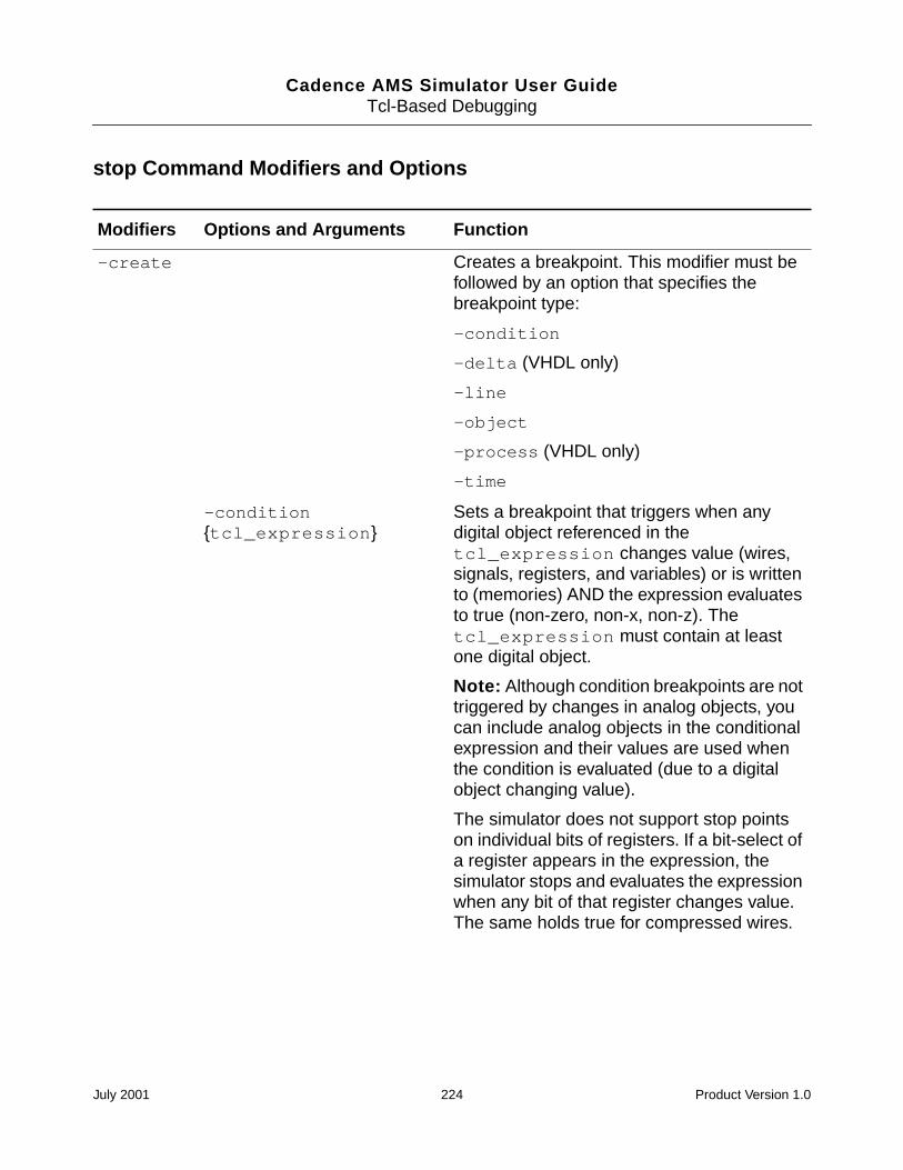
Cadence AMS Simulator User GuideTcl-Based Debugging
stop Command Modifiers and Options
Modifiers Options and Arguments Function
-create Creates a breakpoint. This modifier must befollowed by an option that specifies thebreakpoint type:
-condition
-delta (VHDL only)
-line
-object
-process (VHDL only)
-time
-conditiontcl_expression
Sets a breakpoint that triggers when anydigital object referenced in thetcl_expression changes value (wires,signals, registers, and variables) or is writtento (memories) AND the expression evaluatesto true (non-zero, non-x, non-z). Thetcl_expression must contain at leastone digital object.
Note: Although condition breakpoints are nottriggered by changes in analog objects, youcan include analog objects in the conditionalexpression and their values are used whenthe condition is evaluated (due to a digitalobject changing value).
The simulator does not support stop pointson individual bits of registers. If a bit-select ofa register appears in the expression, thesimulator stops and evaluates the expressionwhen any bit of that register changes value.The same holds true for compressed wires.
July 2001 224 Product Version 1.0
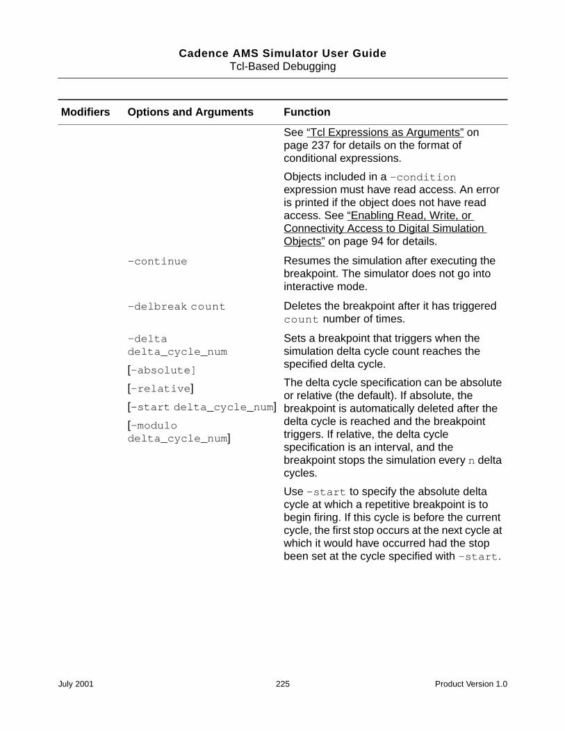
Cadence AMS Simulator User GuideTcl-Based Debugging
See “Tcl Expressions as Arguments” onpage 237 for details on the format ofconditional expressions.
Objects included in a -conditionexpression must have read access. An erroris printed if the object does not have readaccess. See “Enabling Read, Write, orConnectivity Access to Digital SimulationObjects” on page 94 for details.
-continue Resumes the simulation after executing thebreakpoint. The simulator does not go intointeractive mode.
-delbreak count Deletes the breakpoint after it has triggeredcount number of times.
-deltadelta_cycle_num
[-absolute]
[-relative]
[-start delta_cycle_num]
[-modulodelta_cycle_num]
Sets a breakpoint that triggers when thesimulation delta cycle count reaches thespecified delta cycle.
The delta cycle specification can be absoluteor relative (the default). If absolute, thebreakpoint is automatically deleted after thedelta cycle is reached and the breakpointtriggers. If relative, the delta cyclespecification is an interval, and thebreakpoint stops the simulation every n deltacycles.
Use -start to specify the absolute deltacycle at which a repetitive breakpoint is tobegin firing. If this cycle is before the currentcycle, the first stop occurs at the next cycle atwhich it would have occurred had the stopbeen set at the cycle specified with -start.
Modifiers Options and Arguments Function
July 2001 225 Product Version 1.0
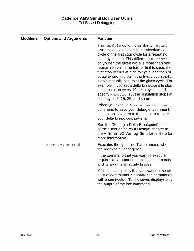
Cadence AMS Simulator User GuideTcl-Based Debugging
The -modulo option is similar to -start.Use -modulo to specify the absolute deltacycle of the first stop cycle for a repeatingdelta cycle stop. This differs from -startonly when the given cycle is more than onerepeat interval in the future. In this case, thefirst stop occurs at a delta cycle less than orequal to one interval in the future such that astop eventually occurs at the given cycle. Forexample, if you set a delta breakpoint to stopthe simulation every 10 delta cycles, andspecify -modulo 15, the simulation stops atdelta cycle 5, 15, 25, and so on.
When you execute a save -environmentcommand to save your debug environment,this option is written to the script to restoreyour delta breakpoint pattern.
See the “Setting a Delta Breakpoint” sectionof the “Debugging Your Design” chapter inthe Affirma NC Verilog Simulator Help formore information.
-execute command Executes the specified Tcl command whenthe breakpoint is triggered.
If the command that you want to executerequires an argument, enclose the commandand its argument in curly braces.
You also can specify that you want to executea list of commands. Separate the commandswith a semi-colon. Tcl, however, displays onlythe output of the last command.
Modifiers Options and Arguments Function
July 2001 226 Product Version 1.0
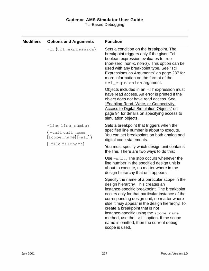
Cadence AMS Simulator User GuideTcl-Based Debugging
-if tcl_expression Sets a condition on the breakpoint. Thebreakpoint triggers only if the given Tclboolean expression evaluates to true(non-zero, non-x, non-z). This option can beused with any breakpoint type. See “TclExpressions as Arguments” on page 237 formore information on the format of thetcl_expression argument.
Objects included in an -if expression musthave read access. An error is printed if theobject does not have read access. See“Enabling Read, Write, or ConnectivityAccess to Digital Simulation Objects” onpage 94 for details on specifying access tosimulation objects.
-line line_number
-unit unit_name |[scope_name] [-all]
[-file filename]
Sets a breakpoint that triggers when thespecified line number is about to execute.You can set breakpoints on both analog anddigital code statements.
You must specify which design unit containsthe line. There are two ways to do this:
Use -unit. The stop occurs whenever theline number in the specified design unit isabout to execute, no matter where in thedesign hierarchy that unit appears.
Specify the name of a particular scope in thedesign hierarchy. This creates aninstance-specific breakpoint. The breakpointoccurs only for that particular instance of thecorresponding design unit, no matter whereelse it may appear in the design hierarchy. Tocreate a breakpoint that is notinstance-specific using the scope_namemethod, use the -all option. If the scopename is omitted, then the current debugscope is used.
Modifiers Options and Arguments Function
July 2001 227 Product Version 1.0
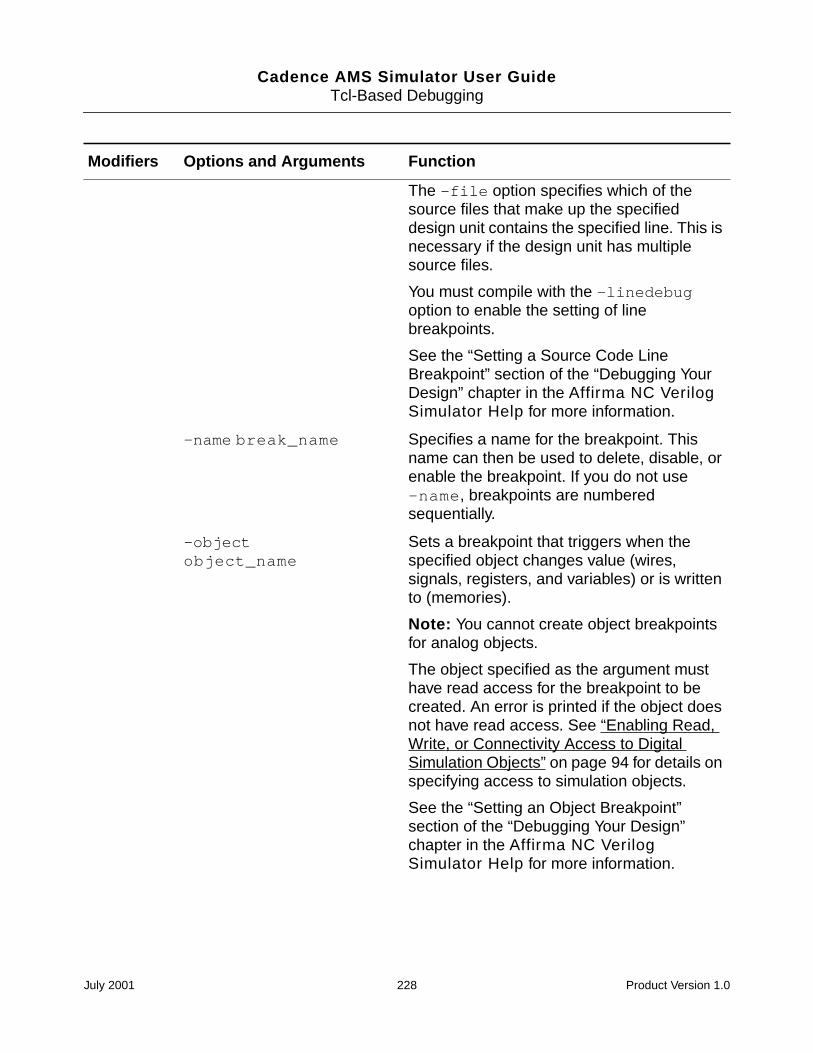
Cadence AMS Simulator User GuideTcl-Based Debugging
The -file option specifies which of thesource files that make up the specifieddesign unit contains the specified line. This isnecessary if the design unit has multiplesource files.
You must compile with the -linedebugoption to enable the setting of linebreakpoints.
See the “Setting a Source Code LineBreakpoint” section of the “Debugging YourDesign” chapter in the Affirma NC VerilogSimulator Help for more information.
-name break_name Specifies a name for the breakpoint. Thisname can then be used to delete, disable, orenable the breakpoint. If you do not use-name, breakpoints are numberedsequentially.
-objectobject_name
Sets a breakpoint that triggers when thespecified object changes value (wires,signals, registers, and variables) or is writtento (memories).
Note: You cannot create object breakpointsfor analog objects.
The object specified as the argument musthave read access for the breakpoint to becreated. An error is printed if the object doesnot have read access. See “Enabling Read,Write, or Connectivity Access to DigitalSimulation Objects” on page 94 for details onspecifying access to simulation objects.
See the “Setting an Object Breakpoint”section of the “Debugging Your Design”chapter in the Affirma NC VerilogSimulator Help for more information.
Modifiers Options and Arguments Function
July 2001 228 Product Version 1.0
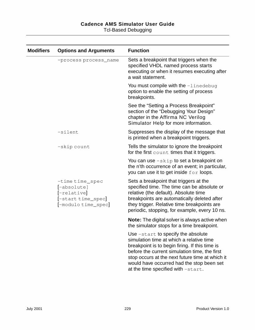
Cadence AMS Simulator User GuideTcl-Based Debugging
-process process_name Sets a breakpoint that triggers when thespecified VHDL named process startsexecuting or when it resumes executing aftera wait statement.
You must compile with the -linedebugoption to enable the setting of processbreakpoints.
See the “Setting a Process Breakpoint”section of the “Debugging Your Design”chapter in the Affirma NC VerilogSimulator Help for more information.
-silent Suppresses the display of the message thatis printed when a breakpoint triggers.
-skip count Tells the simulator to ignore the breakpointfor the first count times that it triggers.
You can use -skip to set a breakpoint onthe n’th occurrence of an event; in particular,you can use it to get inside for loops.
-time time_spec[-absolute][-relative][-start time_spec][-modulo time_spec]
Sets a breakpoint that triggers at thespecified time. The time can be absolute orrelative (the default). Absolute timebreakpoints are automatically deleted afterthey trigger. Relative time breakpoints areperiodic, stopping, for example, every 10 ns.
Note: The digital solver is always active whenthe simulator stops for a time breakpoint.
Use -start to specify the absolutesimulation time at which a relative timebreakpoint is to begin firing. If this time isbefore the current simulation time, the firststop occurs at the next future time at which itwould have occurred had the stop been setat the time specified with -start.
Modifiers Options and Arguments Function
July 2001 229 Product Version 1.0
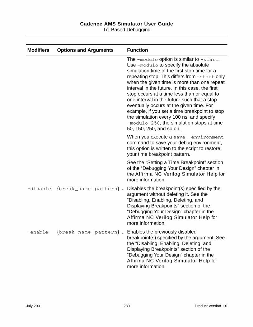
Cadence AMS Simulator User GuideTcl-Based Debugging
The -modulo option is similar to -start.Use -modulo to specify the absolutesimulation time of the first stop time for arepeating stop. This differs from -start onlywhen the given time is more than one repeatinterval in the future. In this case, the firststop occurs at a time less than or equal toone interval in the future such that a stopeventually occurs at the given time. Forexample, if you set a time breakpoint to stopthe simulation every 100 ns, and specify-modulo 250, the simulation stops at time50, 150, 250, and so on.
When you execute a save -environmentcommand to save your debug environment,this option is written to the script to restoreyour time breakpoint pattern.
See the “Setting a Time Breakpoint” sectionof the “Debugging Your Design” chapter inthe Affirma NC Verilog Simulator Help formore information.
-disable break_name | pattern ... Disables the breakpoint(s) specified by theargument without deleting it. See the“Disabling, Enabling, Deleting, andDisplaying Breakpoints” section of the“Debugging Your Design” chapter in theAffirma NC Verilog Simulator Help formore information.
-enable break_name | pattern ... Enables the previously disabledbreakpoint(s) specified by the argument. Seethe “Disabling, Enabling, Deleting, andDisplaying Breakpoints” section of the“Debugging Your Design” chapter in theAffirma NC Verilog Simulator Help formore information.
Modifiers Options and Arguments Function
July 2001 230 Product Version 1.0
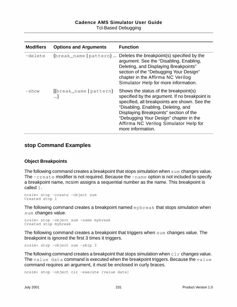
Cadence AMS Simulator User GuideTcl-Based Debugging
stop Command Examples
Object Breakpoints
The following command creates a breakpoint that stops simulation when sum changes value.The -create modifier is not required. Because the -name option is not included to specifya breakpoint name, ncsim assigns a sequential number as the name. This breakpoint iscalled 1.
ncsim> stop -create -object sumCreated stop 1
The following command creates a breakpoint named mybreak that stops simulation whensum changes value.
ncsim> stop -object sum -name mybreakCreated stop mybreak
The following command creates a breakpoint that triggers when sum changes value. Thebreakpoint is ignored the first 3 times it triggers.
ncsim> stop -object sum -skip 3
The following command creates a breakpoint that stops simulation when clr changes value.The value data command is executed when the breakpoint triggers. Because the valuecommand requires an argument, it must be enclosed in curly braces.
ncsim> stop -object clr -execute value data
-delete break_name | pattern ... Deletes the breakpoint(s) specified by theargument. See the “Disabling, Enabling,Deleting, and Displaying Breakpoints”section of the “Debugging Your Design”chapter in the Affirma NC VerilogSimulator Help for more information.
-show [break_name | pattern...]
Shows the status of the breakpoint(s)specified by the argument. If no breakpoint isspecified, all breakpoints are shown. See the“Disabling, Enabling, Deleting, andDisplaying Breakpoints” section of the“Debugging Your Design” chapter in theAffirma NC Verilog Simulator Help formore information.
Modifiers Options and Arguments Function
July 2001 231 Product Version 1.0
Cadence AMS Simulator User GuideTcl-Based Debugging
The following command creates a breakpoint that triggers when clr changes value. Thevalue data command is executed when the breakpoint triggers. The -continue optionprevents the simulator from entering interactive mode every time the stop triggers.
ncsim> stop -object clr -execute value data -continue
The following command creates an object breakpoint that triggers when data changesvalue. The -delbreak option specifies that the breakpoint is deleted after it triggers threetimes.
ncsim> stop -object data -continue -delbreak 3
The following command creates a breakpoint that triggers when clk changes value, but onlyif clk is high. See “Tcl Expressions as Arguments” on page 237 for details on the syntax ofthe argument to the -if option.
ncsim> stop -object clk -if #clk == 1 -continue
The following command creates a breakpoint that triggers when data[1] has the value 1and the time becomes greater than 3 ns.
stop -object data -if #data[1] == 1 && [time ns -nounit] > 3
The following command shows the error message that is displayed if you run in regressionmode and then try to set an object breakpoint on an object that does not have read access.
ncsim> stop -object clkncsim: *E,RDACRQ: Object does not have read access: hardrive.clk.
The following shows an error caused by trying to create a breakpoint on an analog object.
ncsim> stop -object compSigncsim: *W,STALOB: Cannot set stop on analog object:
top.dac.compSig. This object ignored.ncsim: *E,STOBEX: Object expected after -OBJECT
option of stop command.
Line Breakpoints
The following command creates a breakpoint that stops simulation when line number 10 inthe current debug scope is about to execute.
ncsim> stop -line 10
The following command creates a breakpoint that stops simulation when line number 13 inscope counter is about to execute.
ncsim> stop -line 13 counter
In the following command, the -all option specifies that the stop is noninstance-specific.The breakpoint occurs on all scopes which are instances of the same module. For exampleif there are two instances of module m16, as follows:
July 2001 232 Product Version 1.0
Cadence AMS Simulator User GuideTcl-Based Debugging
module board;
<declarations>
m16 counter1 (...);
m16 counter2 (...);
<code>
endmodule
the breakpoint triggers when line 13 in either counter1 or counter2 is about to execute.
ncsim> stop -line 13 counter1 -all
The following command is equivalent to the command shown in the previous example. Bothcommands create non-instance-specific breakpoints.
ncsim> stop -line 13 -unit m16
In the following example, the -file option specifies which of the source files that make upthe given scope (or the debug scope if none is given) contains the specified line. This isnecessary if the scope has multiple source files.
ncsim> stop -line 13 counter -file foo.v
Time Breakpoints
The following command creates a breakpoint that stops simulation at absolute time 200 ns.The breakpoint is automatically deleted after it triggers.
ncsim> stop -time 200 ns -absolute
The following command creates a repetitive breakpoint that stops the simulation every 200ns and then executes the value command. The -relative option is the default for timebreakpoints.
ncsim> stop -time 200 ns -relative -execute value data
The following command creates a repetitive breakpoint that stops the simulation every 200ns. The -start option specifies the absolute time at which the breakpoint starts. Forexample, if the current simulation time is 300 ns, the breakpoint stops the simulation at time600, 800, 1000, and so on.
ncsim> stop -time 200 ns -start 600 ns
In the following example, assume that the current simulation time is 300 ns. The absolute timespecified with -start is before the current simulation time. The first stop occurs at the nextfuture time at which it would have occurred had the stop been set at the time specified with-start. In this example, the first stop occurs at time 450 ns.
ncsim> stop -time 200 ns -start 250 ns
July 2001 233 Product Version 1.0
Cadence AMS Simulator User GuideTcl-Based Debugging
The following example shows how the -modulo option is used to save a breakpoint pattern.Suppose that you simulate to time 300 ns and then set a repetitive breakpoint with thefollowing command:
ncsim> stop -time 200 ns -start 350 ns
This command stops the simulation at time 350, 550, 750, and so on. If you then execute asave -environment command to save your debug environment, the following line iswritten to the script:
stop -create -name 1 -time 200 NS -relative -modulo 950 NS
If you then exit and re-enter the simulation and source the script containing this command,the breakpoint pattern is re-established. In this example, if you reinvoke the simulation andstart at time 0, the breakpoint triggers the first time at time 150. It then triggers at 350, 550,750, and so on.
The following command includes the -if option to set a breakpoint at time 100 ns (relative)if data[1] has the value 1.
ncsim> stop -time 100 ns -if #data[1] == 1
Delta Breakpoints
The following command creates a breakpoint that stops the simulation when it reaches 20delta cycles. The breakpoint is automatically deleted after it triggers.
ncsim> stop -delta 20 -absolute
The following command creates a repetitive breakpoint that stops the simulation every 10delta cycles. The -start option specifies the absolute delta cycle at which the breakpointstarts. For example, if the current delta cycle count is 0, the breakpoint stops the simulationwhen the delta cycle count is 30, 40, 50, and so on.
ncsim> stop -delta 10 -start 30
Condition Breakpoints
In a condition breakpoint, the argument to the -condition option is a Tcl expression. See“Tcl Expressions as Arguments” on page 237 for more information on writing theseexpressions.
The following command sets a condition breakpoint that stops the simulation when count,the output of a 32-bit counter, has the value 100, decimal. The signal count is available fromthe top level of the hierarchy.
Verilog: ncsim> stop -condition [value %d top.count] = 100
VHDL: ncsim> stop -condition [value %d :count] = 100
July 2001 234 Product Version 1.0
Cadence AMS Simulator User GuideTcl-Based Debugging
If you are currently at the top level, you can omit the hierarchical path specification to count,and the two commands shown in the previous example could be written as follows:
ncsim> stop -condition [value %d count] = 100
The value command uses the value of the vlog_format (or vhdl_format) variable. Ifyou set the value of this variable to %d, the command shown in the previous example couldbe written as follows:
ncsim> stop -condition [value count] = 100
Instead of using the value command to get the value of count into the expression evaluator,you can use #count. Include the format specifier after the # sign.
ncsim> stop -condition #%dcount = 100
For Verilog, you can use the standard notation (for example 4’b0011). For example, you canset the breakpoint on count as follows:
ncsim> stop -condition #count = 32’d100
ncsim> stop -condition #count = 32’b00000000000000000000000001100100
VHDL does not have the same type of notation. Vectors must be enclosed in quotation marks,as shown in the next example.
ncsim> stop -condition #count = ”00000000000000000000000001100100”
The following command sets a condition breakpoint that stops the simulation when bit 0 ofcount is 1. The expression is evaluated when any bit of count changes value. For VHDL,single-bit entities must be enclosed in single quotation marks.
Verilog: ncsim> stop -condition #count[0] == 1
VHDL: ncsim> stop -condition #count(0) == ‘1’
The following command is identical to the previous command. An explicit value commandis used to get the value of count(bit 0) into the expression parser.
Verilog: ncsim> stop -condition [value %b count[0]] == 1’b1
VHDL: ncsim> stop -condition [value %b count(0)] == ‘1’
In the following command, the -if option is used to conditionalize the condition breakpoint.This breakpoint stops the simulation at the next positive edge of the clock if en1 or en2 is 1.
Verilog: ncsim> stop -condition #clock == 1 -if #en1 || #en2
VHDL: ncsim> stop -condition #clk_n == ’1’-if #enable==’1’|| #reset_n==’1’
The following command stops the simulation at 5 ns (absolute time). After that, clockchanges depending on the condition in the if expression, and this happens repeatedly every5 ns. The -continue option is used to prevent the simulation from stopping every time thebreakpoint triggers. VHDL requires use of the single quotation marks.
July 2001 235 Product Version 1.0
Cadence AMS Simulator User GuideTcl-Based Debugging
ncsim> stop -time 5 ns -start 5 ns-execute if #clk == ’0’ force clk ’1’else force clk ’0’ -continue
Process Breakpoints
The following command sets a breakpoint that stops the simulation whenever the processcalled :load_action is executed.
ncsim> stop -process :load_action
Examples of Other stop Command Modifiers
The following command sequence illustrates the -show modifier. The first command createsa source line breakpoint called break1; the second creates an object breakpoint calledbreak2. The third command shows the status of the two breakpoints.
ncsim> stop -line 12 -name break1Created stop break1ncsim> stop -object data -name break2Created stop break2ncsim> stop -showbreak1 Enabled Line: ./shortdrive.v:12 (scope: top)break2 Enabled Object top.datancsim>
In the following command sequence, breakpoint break1 is first disabled with the-disable modifier and then enabled with the -enable modifier.
ncsim> stop -showbreak1 Enabled Line: ./shortdrive.v:12 (scope: top)break2 Enabled Object top.datancsim> stop -disable break1ncsim> stop -showbreak1 Disabled Line: ./shortdrive.v:12 (scope: top)break2 Enabled Object top.datancsim> stop -enable break1ncsim>
The following command deletes breakpoint break1.
ncsim> stop -delete break1
To disable, enable, or delete the two breakpoints break1 and break2, any of the followingcommands could be used.
ncsim> stop -delete *1 *2
ncsim> stop -delete break?
ncsim> stop -delete br*
The following command displays information on any breakpoint beginning with v or b.
ncsim> stop -show [vb]*
July 2001 236 Product Version 1.0
Cadence AMS Simulator User GuideTcl-Based Debugging
Tcl Expressions as Arguments
The stop command has two options that let you specify conditions. Both options require aTcl expression argument.
-condition
This option specifies that you are creating a condition breakpoint, as opposed to someother kind of breakpoint, such as a time or object breakpoint. A condition breakpointtriggers when any digital object named in the Tcl expression has an event that wouldtrigger an object breakpoint and the expression evaluates to non-zero, non-x, or non-z.Although condition breakpoints are not triggered by changes in analog objects, you caninclude analog objects in the conditional expression and their values are used when thecondition is evaluated (due to a digital object changing value).
-if
This option can be used with any breakpoint type, including condition breakpoints. TheTcl expression argument is evaluated, and the stop triggers if the expression evaluatesto non-zero, non-x, or non-z.
There are two general rules to keep in mind when writing the Tcl expression:
Enclose the expression in braces to suppress immediate substitution of values.
tcl_expression
Note: If you are using the SimVision analysis environment, these braces are includedon the Set Break form.
In the following example, the value of w[1] would be substituted with its current value(1’bx, for example) if there were no braces. No object would be named in theexpression by the time the stop command routine sees it, resulting in an error.
ncsim> stop -condition #w[1] == 1
ncsim> stop -condition #w[1] == 1
You must use either an explicit value command or the # character to get the object’svalue into the expression parser because the parser does not understand names. Forexample, the following command generates an error message.
ncsim> stop -time 100 ns -if r[1] == 1
Use the following commands:
Verilog:
ncsim> stop -time 100 ns -if [value r[1]] == 1’b1
ncsim> stop -time 100 ns -if #r[1] == 1
VHDL:
ncsim> stop -time 100 ns -if [value r(1)] == ‘1’
July 2001 237 Product Version 1.0
Cadence AMS Simulator User GuideTcl-Based Debugging
ncsim> stop -time 100 ns -if #r(1) == ‘1’
Format specifiers can be used with either the value command or the # sign. If you use the# sign, place the format specifier after the # sign. For example,
Verilog:
ncsim> stop -condition [value %d out] = 12
ncsim> stop -condition #%dout = 12
VHDL:
ncsim> stop -condition [value %d out] = 12
ncsim> stop -condition #%dout = 1
For VHDL, you must enclose vectors in quotation marks and single-bit entities in singlequotation marks. For example,
Verilog: ncsim> stop -condition #clock == 1
VHDL: ncsim> stop -condition #clock == ‘1’
Verilog: ncsim> stop -condition #count = 4’b0101
VHDL: ncsim> stop -condition #clock = “0101”
See the “Basics of Tcl” appendix in the Affirma NC Verilog Simulator Help for more detailson basic Tcl syntax and on the extensions to Tcl that have been added to handle types andoperators of the Verilog and VHDL hardware description languages.
time
The time command displays the current simulation time scaled to the specified unit. The unitcan be:
a time unit that you specify
auto—use the largest base unit that makes the numeric part of the time an integer
module—use the timescale of the current debug scope
The simulation time can be displayed in the following time units:
fs—femtoseconds
ps—picoseconds
ns—nanoseconds
us—microseconds
ms—milliseconds
July 2001 238 Product Version 1.0
Cadence AMS Simulator User GuideTcl-Based Debugging
sec—seconds
If no unit is given, the value of the $display_unit variable is used. This variable is set toauto by default.
You also can display the time in 10 or 100 times the base unit. For example,
ncsim> time fs
ncsim> time 10fs
ncsim> time 100fs
time Command Syntaxtime [[10 | 100]time_unit | auto | module]
-delta
-nounit
time Command Modifiers and Options
time Command Examples% ncsim -tcl boardncsim: v1.0.(p2): (c) Copyright 1995 - 2000 Cadence Design Systems
ncsim> run 100 ns5 count= X, f=x, af=xRan until 100 NS + 0
Modifiers Options andArguments Function
-delta Includes the delta cycle count.
Note: The -delta option is ignored if theanalog solver is active.
At any given simulation time, values of nets arefirst updated and then behaviors that aresensitive to those nets are executed. This twostep process may be repeated any number oftimes because of zero-delays. The delta cyclecount represents the number of times theprocess is repeated for the given simulationtime.
-nounit Does not include the time unit.
July 2001 239 Product Version 1.0
Cadence AMS Simulator User GuideTcl-Based Debugging
The following command displays the current simulation time in ns.
ncsim> time ns100 NS
The following command displays the current simulation time in fs.
ncsim> time fs100000000 FS
The following command displays the current simulation time in 100 times the base unit of fs.
ncsim> time 100fs1000000 100FS
The following commands illustrate the auto keyword, which displays the time using thelargest base unit that makes the numeric part of the time an integer.
ncsim> time fs100000000 FSncsim> time auto100 NS
The following command displays the current simulation time using the timescale of the currentdebug scope.
ncsim> time module100 NS
The following command displays the current simulation time using the timescale of the currentdebug scope and including the delta cycle count.
ncsim> time module -delta100 NS + 0
The following command displays the current simulation time with no time unit.
ncsim> time -nounit100
value
The value command prints the current value of the specified objects using the last formatspecifier preceding the object name argument. If no format is specified, a default format isused.
Objects specified as arguments to the value command must have read access. An error isprinted if an object does not have read access.
For information about using value with unnamed branches, see “Specifying UnnamedBranch Objects” on page 160.
July 2001 240 Product Version 1.0
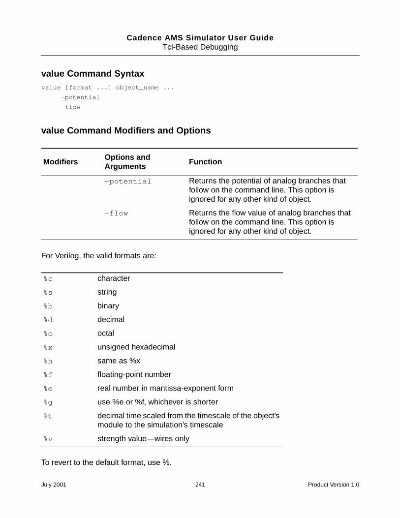
Cadence AMS Simulator User GuideTcl-Based Debugging
value Command Syntaxvalue [format ...] object_name ...
-potential
-flow
value Command Modifiers and Options
For Verilog, the valid formats are:
To revert to the default format, use %.
Modifiers Options andArguments Function
-potential Returns the potential of analog branches thatfollow on the command line. This option isignored for any other kind of object.
-flow Returns the flow value of analog branches thatfollow on the command line. This option isignored for any other kind of object.
%c character
%s string
%b binary
%d decimal
%o octal
%x unsigned hexadecimal
%h same as %x
%f floating-point number
%e real number in mantissa-exponent form
%g use %e or %f, whichever is shorter
%t decimal time scaled from the timescale of the object’smodule to the simulation’s timescale
%v strength value—wires only
July 2001 241 Product Version 1.0
Cadence AMS Simulator User GuideTcl-Based Debugging
If no format is specified, the default format depends on the object type. The following defaultsare used:
analog—%g
time—%d
integer—%d
real—%g
reg—$vlog_format
wire—$vlog_format
where $vlog_format is a predefined Tcl variable that defaults to %h. You can set thisvariable to %b, %o, or %d.
For VHDL, values are returned in a format that resembles the appropriate VHDL syntax forthe object type. If one of the radix format specifiers (%b, %o, %d, or %x) is given, the formataffects the format of integer values and of bit_vector and std_logic_vector values. Otherwise,the format specifier is ignored for VHDL values.
The value of a digital net that is associated with a mixed signal depends on whether theenclosing module is an ordinary module or a connect module. The value of a digital net withinan ordinary module is the resolved value of the connect module drivers that drive the net. Thevalue of a digital net within a connect module is the resolved value of the ordinary moduledrivers that drive the net. For more information, see the “Driver-Receiver Segregation” sectionof the “Mixed-Signal Aspects of Verilog-AMS” chapter, in the Cadence Verilog-AMSLanguage Reference.
Pound Sign (#) Value Command
You can also use the pound sign (#) as a shortcut to the value command. When used on ananalog branch the # shortcut accesses the potential across the branch, not the flow.
value Command Examples
You have an analog branch declared in Verilog-AMS source code like this:
branch (p,n) res ;
You can return the potential of the branch like this:
ncsim> value res0.626
July 2001 242 Product Version 1.0
Cadence AMS Simulator User GuideTcl-Based Debugging
Where the flow of the res and bar branches are 0.111mA and 2.3mA respectively, and thepotential of the p_n branch is 4.666V, using the command
ncsim> value -flow res bar -potential p_n
returns
0.000111 0.00023 4.666
The following sequence of value commands displays the current value of data in a varietyof formats.
ncsim> value data4’h2ncsim> value %o data4’o02ncsim> value %b data4’b0010ncsim> value %d data4’d2ncsim> value %g data2ncsim> value %f data2.000000ncsim> value %e data2.000000e+00
ncsim> value %b data %d q4’b0010 4’d1ncsim> value % data %d data %b data4’h2 4’d2 4’b0010
The following command shows the error message that is displayed when you run inregression mode and use the value command on an object that does not have read access.
ncsim> value clkncsim: *E,RDACRQ: Object does not have read access: hardrive.clk.
where
The where command displays the current location of the simulation. This includes the currentsimulation time and the current scope.
where Command Syntaxwhere
where Command Modifiers and Options
None.
July 2001 243 Product Version 1.0
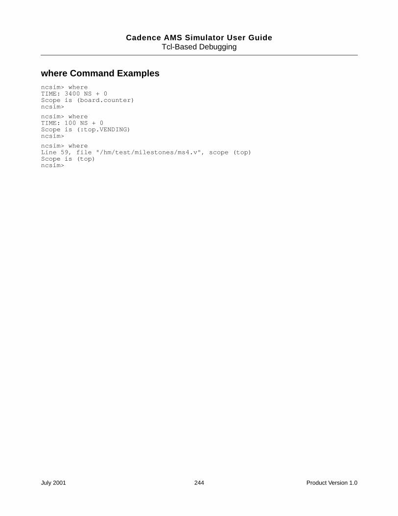
Cadence AMS Simulator User GuideTcl-Based Debugging
where Command Examplesncsim> whereTIME: 3400 NS + 0Scope is (board.counter)ncsim>
ncsim> whereTIME: 100 NS + 0Scope is (:top.VENDING)ncsim>
ncsim> whereLine 59, file "/hm/test/milestones/ms4.v", scope (top)Scope is (top)ncsim>
July 2001 244 Product Version 1.0
Cadence AMS Simulator User Guide
Glossary
A
access functionThe method by which flows and potentials are accessed on nets, ports, and branches.
analog procedural blockA procedural sequence of statements that defines the behavioral description of acontinuous time simulation.
B
branchA path between two nodes. Each branch has two associated quantities, a potential anda flow, with a reference direction for each.
C
connect moduleA module automatically or manually inserted by using the connect statement, whichcontains the code required to translate and propagate signals between nets that havedifferent discipline domains and that are connected via a port. Connect modules arealso known as interface elements.
D
digital islandThe set of drivers and receivers interconnected by a purely digital net.
discipline resolutionThe process of assigning a discipline to every net of every mixed-signal in a design.
driverA primitive device or behavioral construct that affects the digital value of a signal.
July 2001 245 Product Version 1.0
Cadence AMS Simulator User GuideGlossary
driver-receiver segregationThe separation, in a mixed signal, of digital drivers from digital receivers. When driversand receivers are segregated, signals propagate only through connect modules.
M
mixed busA bus comprising at least one net from the analog domain and at least one net from thedigital domain.
O
ordinary moduleAny module other than a connect module.
R
receiverA primitive device or behavioral construct that samples the digital value of a signal.
S
signalA hierarchical collection of nets which, because of port connections, are contiguous.
July 2001 246 Product Version 1.0