Embed Size (px)
Citation preview
Cable Network TransparencyF i b e r O p t i c M o n i t o r i n g
Fault recognition, localisation and reporting

The demand for complex fiberoptic cable networks and flexible IPdata traffic increases exponentiallyconcurrently with the demand fornetwork services - thus requiringconstant and high transfer rates.
An efficient fiber optic cable moni-toring is essential for succeeding inthis aim - made by LANCIER Moni-toring.
2
F u t u r e o f T e l e c o m m u n i c a t i o n
F i b e r O p t i c C a b l e
F i b e r O p t i c C a b l e M o n i t o r i n gi s e s s e n t i a l y r e q u i r e d
Fiber optic cable has unexpectedly turned out to be sensitive to environmentalinfluences. For example penetrating humidity is influencing the transmission quali-ty. Ruptures due to ground movements, construction works or even theft maycause total loss. Thus fiber optic cables must be monitored as well.
The transmission quality over the entire cable is measuredusing attenuation values in a reference fiber. In this processstate-of-the-art sensor technology results in quick and pre-cise fault detection.
Top-quality OTDRs(Optical Time DomainReflectometers) areused to point the faultlocation precisely.OTDRs tailored to therelevant transmissionwavelength are em -ployed as the particular task dictates.
The LANCIER Monitoring Fiber Optic Monitoring System offers to you• permanent preventive monitoring,
• short response time when faults occur = no or only short down times,
• fault location if reflectometer (OTDR) is implemeted in the monitoring system,
• monitoring of active and dark fibres,
• monitoring of optical performance,
• monitoring of optical attenuation,
• monitoring using reflectometers (OTDR),
• monitoring for humidity penetration.
T h e c o r e
o f F a u l t L o c a t i o n a t O p t i c F i b e r s
O T D R
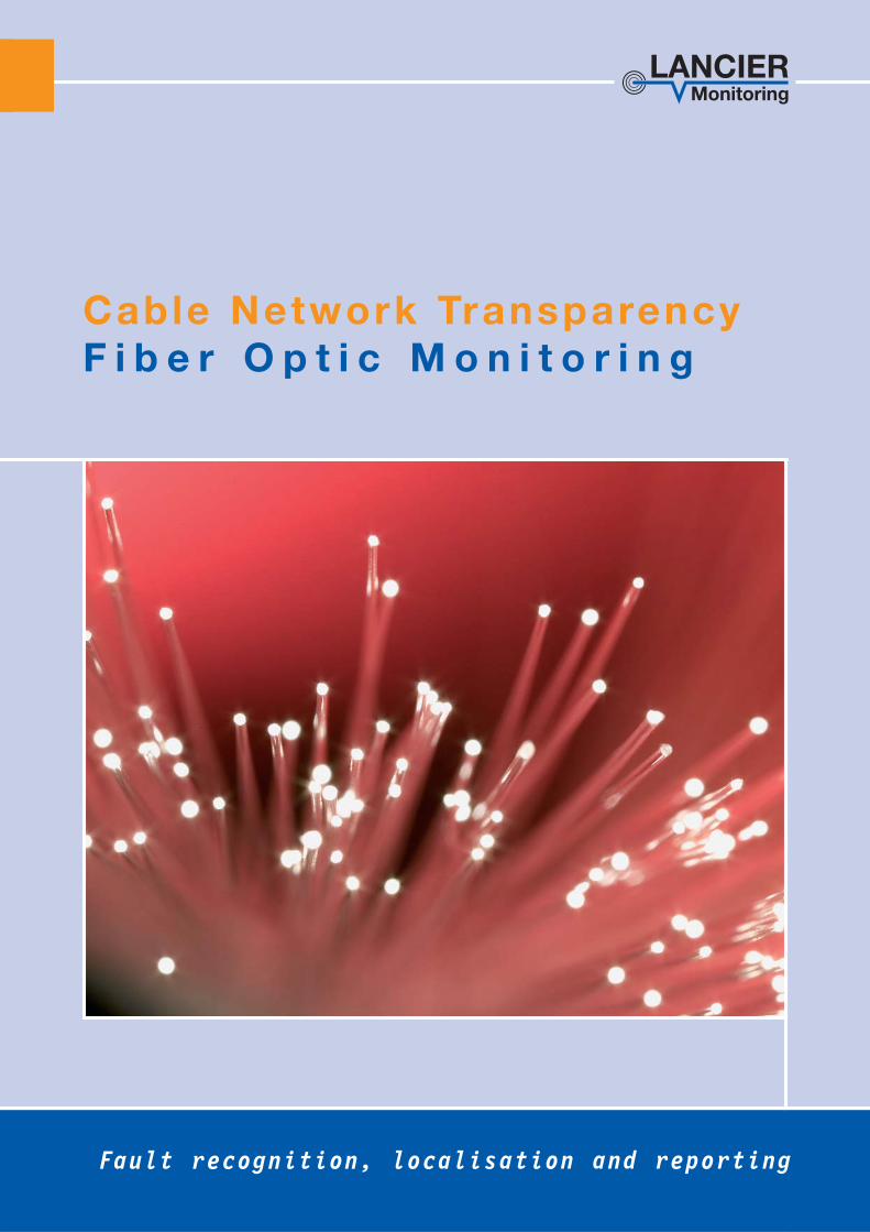
Embedding an OTDR with optical switch into theRTU upgrades the Unified Monitoring System (UMS)to a precise fiber optic fault-location system.
The use of optical switchesallows for the monitoring of analmost unlimited number of opticfibers which are measured con-secutively.
Even dark fibers might be moni-tored due to the application ofWDM (wavelength division multi-plexers).
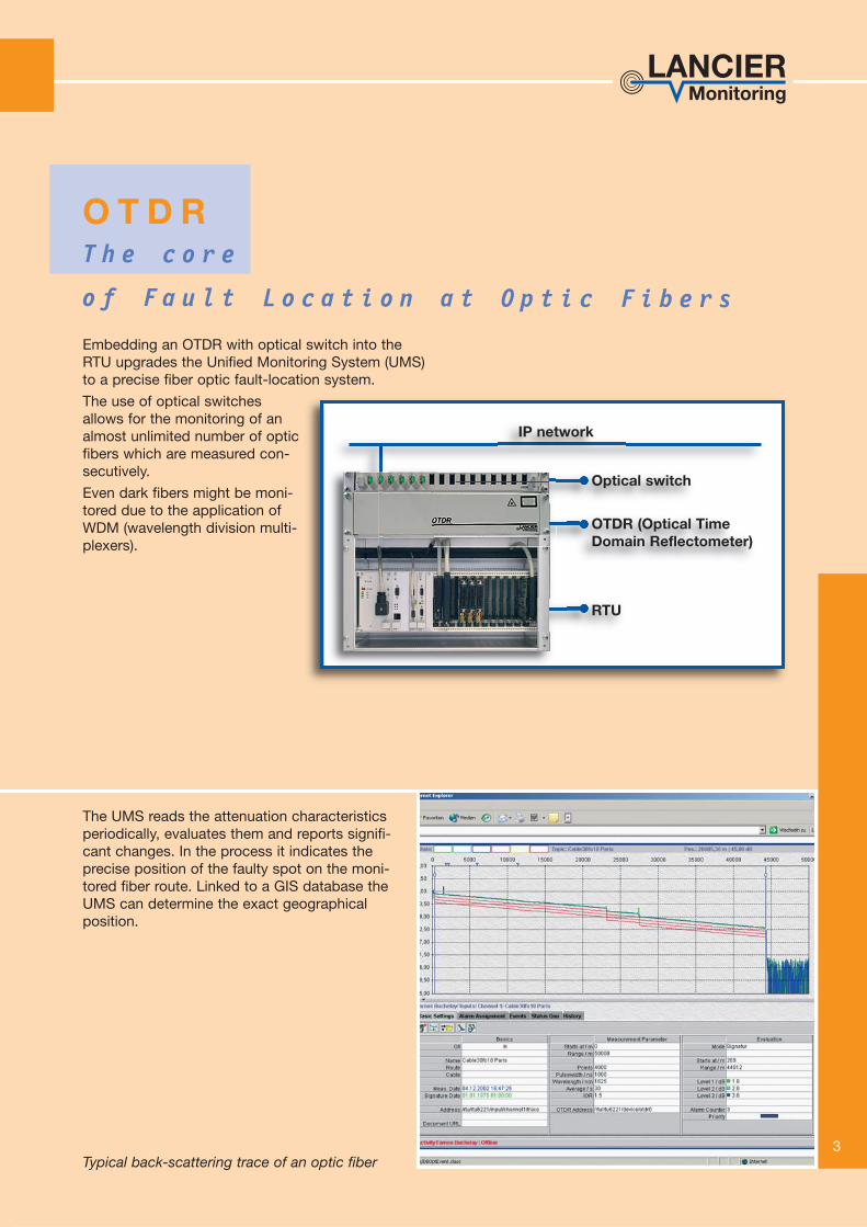
The UMS reads the attenuation characteristicsperiodically, evaluates them and reports signifi-cant changes. In the process it indicates theprecise position of the faulty spot on the moni-tored fiber route. Linked to a GIS database theUMS can determine the exact geographicalposition.
Optical switch
OTDR (Optical TimeDomain Reflectometer)
RTU
Typical back-scattering trace of an optic fiber
IP network
3

4
M o n i t o r i n g p r o v i d e s S e c u r i t y
O p t i c a l L o s s
Fiber optic pair
Loop Measurementof a fiber optic pair
Fiber optic trunk cable
Serial Measurementof an optic fiber
The FiberTxA-Mk2 is a stand-alone measurement and monitoring devicefor dark and active optical fibers. Loop or serial measurements are con-tinuously executed on a spare optical fiber.
The thresholds for the attenuation values are easily programmable withthe built-in keys. The integrated display shows the measurement valuesand settings.
Monitoring the optical attenuation detects• breaks and kinks of dark fibers
• humidity ingress - in conjunction with the AquaSensor(only at 1625 nm, see rear page)
• security breaches through tapping with bendingcouplers (only at 1625 nm)
5
M o n i t o r i n g p r o v i d e s a g e n e r a l S u r v e y
O p t i c a l P o w e r
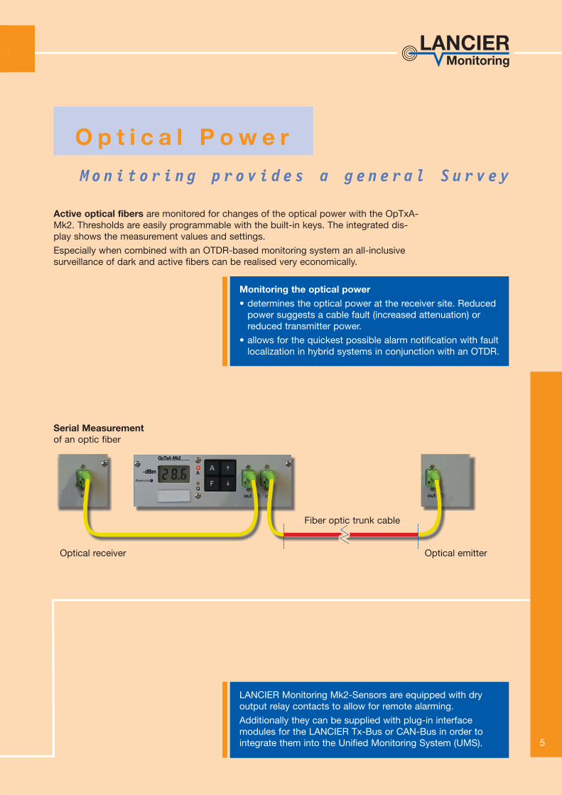
Serial Measurementof an optic fiber
Fiber optic trunk cable
Optical receiver Optical emitter
Active optical fibers are monitored for changes of the optical power with the OpTxA-Mk2. Thresholds are easily programmable with the built-in keys. The integrated dis-play shows the measurement values and settings.
Especially when combined with an OTDR-based monitoring system an all-inclusivesurveillance of dark and active fibers can be realised very economically.
LANCIER Monitoring Mk2-Sensors are equipped with dryoutput relay contacts to allow for remote alarming.
Additionally they can be supplied with plug-in interfacemodules for the LANCIER Tx-Bus or CAN-Bus in order tointegrate them into the Unified Monitoring System (UMS).
Monitoring the optical power • determines the optical power at the receiver site. Reduced
power suggests a cable fault (increased attenuation) orreduced transmitter power.
• allows for the quickest possible alarm notification with faultlocalization in hybrid systems in conjunction with an OTDR.
6
SMSE-Mail
FaxPager...
Report
Server
NMS (Network Management System)
Cable management system
GIS (Geographical Information System)
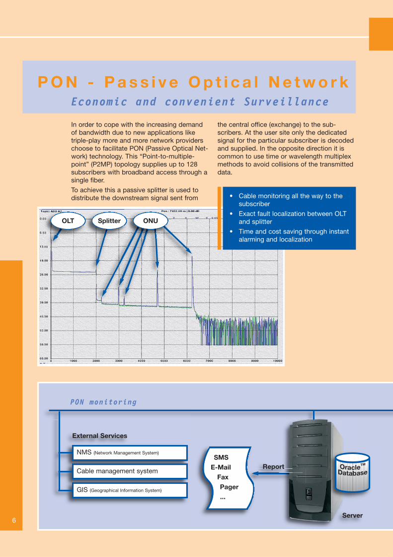
PON monitoring
External Services
Economic and convenient Surveillance
P O N - P a s s i v e O p t i c a l N e t w o r k
In order to cope with the increasing demandof bandwidth due to new applications liketriple-play more and more network providerschoose to facilitate PON (Passive Optical Net-work) technology. This “Point-to-multiple-point” (P2MP) topology supplies up to 128subscribers with broadband access through asingle fiber.
To achieve this a passive splitter is used todistribute the downstream signal sent from
the central office (exchange) to the sub-scribers. At the user site only the dedicatedsignal for the particular subscriber is decodedand supplied. In the opposite direction it iscommon to use time or wavelength multiplexmethods to avoid collisions of the transmitteddata.
• Cable monitoring all the way to thesubscriber
• Exact fault localization between OLTand splitter
• Time and cost saving through instantalarming and localization
OLT Splitter ONU

7
IP network
Client
The LANCIER Monitoring system for PON is com-pact and modular. The RTU (Remote Testing Unit) isinstalled in the central office (exchange). The built-inhigh-end OTDR comes with three measurementwavelengths (1310 nm, 1550 nm and 1625 nm) tobe prepared for any measurement task and state-of-the-art deadzones, which makes PON monitoringpossible in the first place. An optical switch with thenecessary amount of fiber connectors sequentiallyattaches the fibers to be measured to the OTDR.
If the transmission equipment installed in the centraloffice is not already equipped with monitoring chan-
nels, additional wave division multiplexers (WDM)are used to couple the monitoring signal into theactive fibers.
The OTDR then measures the fiber even past thepassive splitter all the way down to the ONUs (sub-scriber site). During the measurement the endreflection is evaluated to determine whether theconnection between splitter and ONU is still fullyfunctional. Additionally an exact fault localizationbetween the OLT and the splitter is possible, whichsaves even more time for the diagnostics.
Optical switch
OTDR (Optical TimeDomain Reflectometer)
RTU
PONWDMWDMWDM WDM
SplitterSplitter
SplitterSplitter ONU
ONU
ONU
ONU
ONU
ONUONU
(Optical line terminal)
OLT... ...
WDM = wavelength division multiplexers to couple in the monitoring signal | ONU = Optical Network Unit (end user)

LANCIER Monitoring GmbHGustav-Stresemann-Weg 1148155 Münster, GermanyTel. +49 (0) 251 674 999-0Fax +49 (0) 251 674 999-99 www.lancier-monitoring.de 07
3961
.020
K
o/11
.10
A
ltera
tions
res
erve
d.
H u m i d i t y t h r e a t e n s O p t i c F i b e r s
T h e A q u a S e n s o r i s t h e r e m e d y
Water penetrating into splicing boxes, e.g. through damage of the sleeve,imperfect sealing or a defective cable sheath, embrittles the fiber opticcable and causes microcracks. In the long term, this leads to deteri-oration of the fiber properties or even to an unexpected total loss ofsignal transmission.
The reliably working LANCIER AquaSensor early-warning systemhelps to ob viate these consequences. If the AquaSensorcomes into contact with humidity, the fiber is bent in acontrolled way to generate a measurable increase ofattenuation.
These changes can be shown as graphic representa-tion using the LANCIER Monitoring System.
The LANCIER AquaSensor can be inserted into all current splice holders, and no metallic conductor is required for signalling.
A LANCIER FiberTxA-Mk2 sensor or an OTDR are required to read the AquaSensor.
AquaSensor
AquaSensor mounted in a splicing box
The LANCIER AquaSensor• reports humidity and water pene-
tration into fiber optic joints,
• has short response times,
• allows for exact fault localisationby the UMS,
• is re-usable after fault report dueto the reversible behaviour of thehumidity measuring tape,
• can be mounted quickly and easilyinto the splice holder.