Embed Size (px)
Citation preview
41388601TH Rev.6 1 / 142
Oki Data CONFIDENTIAL
C9400/C9200Color LED Page PrinterMAINTENANCEMANUAL
ODA/OEL/INT
2002-12-10 Rev.6
41388601TH Rev.6 2 /
Oki Data CONFIDENTIAL
1 2000-12-05 ISSUE EM3 Murakami
2 2000-12-13 8 Correction of errors in K Yamazakithe parts list
3 2001-05-15 CN11 Kasuya
4 2001-10-12 K Yamazaki
5 2002-11-27 K Yamazaki
6 2002-12-10 NP34 Ueda
Rev.No. DateNo.
Corrected items
Page Description of change
Person incharge
Document Revision History
41388601TH Rev.6 3 /
Oki Data CONFIDENTIAL
PREFACE
This maintenance manual provides procedures and techniques for the troubleshooting, maintenance, andrepair of C9400/C9200.
This manual is written for maintenance personnel, but it should always be accompanied with the C9400/C9200 User’s Manual for procedures for handling and operating C9400/C9200. For repairing eachcomponent of C9400/C9200, see the Troubleshooting manual.
[Notices]The contents of this manual are subject to change without prior notice.Although reasonable efforts have been taken in the preparation of this manual to assure its accuracy, thismanual may still contain some errors and omissions. OKI will not be liable for any damage caused oralleged to be caused, by the customer or any other person using this maintenance manual to repair,modify, or alter C9400/C9200 in any manner.
[Warning]Many parts of C9400/C9200 are very sensitive and can be easily damaged by improper servicing. Westrongly suggest that C9400/C9200 be serviced by OKI’s authorized technical service engineers.
41388601TH Rev.6 4 /
Oki Data CONFIDENTIAL
CONTENTS
1. SPECIFICATIONS ............................................................................................ 6
1.1 Basic System Configuration ............................................................................................. 61.2 Printer Engine Specifications ........................................................................................... 71.3 Option Configuration ........................................................................................................ 81.4 Specifications ................................................................................................................... 9
2. PARTS REPLACEMENT................................................................................ 11
2.1 Precautions in Replacing Parts ...................................................................................... 112.2 Parts Layout ................................................................................................................... 132.3 Replacing Parts .............................................................................................................. 20
2.3.1 Top cover.......................................................................................................... 212.3.2 LED Assy/ LED Assy spring ............................................................................. 222.3.3 Top cover unit ................................................................................................... 232.3.4 Control panel Assy/ Control panel bezel/ LED control PWB/ Toner sensor/
Stack full sensor/ Control panel tape harness/ Eject roller ............................... 242.3.5 Top cover handle/ Tope cover latch/ Top cover latch spring ............................ 252.3.6 Eject guide Assy ............................................................................................... 262.3.7 Cassette Assy/ Blind cover/ Side cover R Assy ............................................... 272.3.8 Feed rollers ....................................................................................................... 282.3.9 Left side cover .................................................................................................. 292.3.10 Face-up tray ..................................................................................................... 302.3.11 Front cover ....................................................................................................... 312.3.12 Rear cover ........................................................................................................ 322.3.13 Multipurpose tray Assy/ Multipurpose tray cover Assy/ Links/
Multipurpose tray top cover/ Multipurpose tray drive gear ................................ 332.3.14 Drum contact Assys.......................................................................................... 342.3.15 Registration roller Assy (A)/ Registration drive gear (A) ................................... 352.3.16 Registration roller Assy (B) ............................................................................... 362.3.17 Registration clutch, Registration motor Assy .................................................... 372.3.18 Cooling fan ....................................................................................................... 382.3.19 Color registration sensor Assy.......................................................................... 392.3.20 Duplex guide Assy ............................................................................................ 402.3.21 Electrical chassis/ Electrical chassis cooling fan .............................................. 412.3.22 Printer engine controller PWB .......................................................................... 422.3.23 Printer unit chassis ........................................................................................... 432.3.24 Entrance cassette sensor actuator ................................................................... 442.3.25 Entrance sensor PWB ...................................................................................... 452.3.26 Entrance MT sensor actuator and Entrance belt sensor actuator .................... 462.3.27 Main motor fan/ Fuser eject roller ..................................................................... 472.3.28 Eject sensor Assy ............................................................................................. 482.3.29 Fuser latching handle (L) .................................................................................. 492.3.30 Belt motor Assy ................................................................................................ 502.3.31 Fuser latching handle (R) ................................................................................. 512.3.32 Main motor Assy ............................................................................................... 522.3.33 Contact Assy/ Side plate Assy.......................................................................... 532.3.34 Low voltage power supply ................................................................................ 542.3.35 High voltage power supply ............................................................................... 552.3.36 Main feed Assy ................................................................................................. 562.3.37 Fuser unit .......................................................................................................... 572.3.38 Belt unit ............................................................................................................. 582.3.39 Duplex unit ........................................................................................................ 592.3.40 CU Assy............................................................................................................ 60
41388601TH Rev.6 5 /
Oki Data CONFIDENTIAL
3. Adjustment .................................................................................................... 62
3.1 Maintenance Menu and Its Functions ............................................................................ 623.2 Short Plug Settings ........................................................................................................ 633.3 Printing Singly Using Controller-Equipped Printer ......................................................... 633.4 Adjustment after Part Replacement ............................................................................... 643.5 Color Balance Adjustment ............................................................................................. 653.6 EEPROM Replacement after SWA Board and K73 Board Replacement ...................... 67
4. Regular Maintenance .................................................................................... 68
4.1 Parts to be Replaced Regularly ..................................................................................... 684.2 Cleaning ......................................................................................................................... 684.3 Cleaning of LED Lens Array .......................................................................................... 684.4 Cleaning of Pick-up Roller ............................................................................................. 68
5. TROUBLESHOOTING PROCEDURES ......................................................... 69
5.1 Tips for Troubleshooting ................................................................................................ 695.2 Check Points before Correcting Image Problems .......................................................... 695.3 Tips for Correcting Image Problems .............................................................................. 695.4 Preparation for Troubleshooting .................................................................................... 705.5 Troubleshooting Flow..................................................................................................... 70
5.5.1 LCD Message List ............................................................................................ 715.5.2 LCD message troubleshooting ......................................................................... 795.5.3 Image troubleshooting ...................................................................................... 90
6. WIRING DIAGRAM...................................................................................... 102
6.1 Resistance Check ........................................................................................................ 1026.2 Parts Layout on Boards ............................................................................................... 107
7. Parts List ...................................................................................................... 111
7.1 Printer Unit Parts List ................................................................................................... 1117.2 C9400/C9200 Finisher for OEL/INT Parts Layout ........................................................ 131
41388601TH Rev.6 6 /
Oki Data CONFIDENTIAL
Job
offs
et
MM
M
M
M
M
M
LED
Hea
d
Junc
tion
Boa
rd
Pul
se M
otor
s
Eng
ine
Con
trol
ler
Low
-Vol
tage
P
ower
Uni
t
Fus
er U
nit
Hig
h-V
olta
ge
Pow
er U
nit
2nd/
3rd
Tray
/La
rge-
Cap
acity
Tray
Dup
lex
Uni
t
Bel
t Uni
t
<S
enso
rs, S
witc
hes
and
The
rmis
tors
>P
aper
car
rier
sens
ors
Pap
er s
ize
dete
ctio
nF
user
tem
pera
ture
det
ectio
nA
mbi
ent t
empe
ratu
re a
nd h
umid
ity d
etec
tion
Tone
r re
mai
ning
det
ectio
nC
olor
reg
istr
atio
n se
nsor
ID, b
elt a
nd fu
ser
chec
ks
C-I
DU
nit
M-I
DU
nit
Y-ID
Uni
tK
-ID
Uni
t
C ID
M
Hea
ter
M ID
Y ID
K ID
Bel
tM
T/
Reg
istr
atio
n Hop
ping
Gea
red
mot
or
DC
mot
or
Ope
rato
r P
anel
Cen
tron
ics
US
B
IDE
HD
D
DC
FAN
Eth
erne
t
RO
M D
IMM
× 3
SD
RA
M D
IMM
× 4
Con
trol
ler
Blo
ck
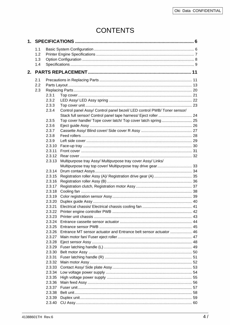
1. SPECIFICATIONS
1.1 Basic System Configuration
The basic system configuration of C9400/C9200 is illustrated in Figure 1.1.
Fig
ure
1.1
41388601TH Rev.6 7 /
Oki Data CONFIDENTIAL
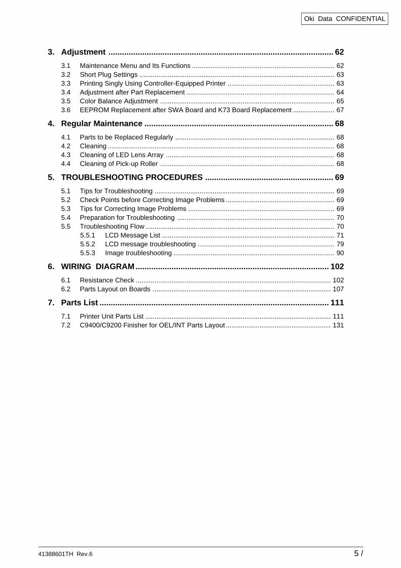
1.2 Printer Engine Specifications
The inside of the printer is composed of the followings:
• Electrophotographic Processor• Paper Paths• Controller Block (CU and PU)• Operator Panel• Power Units (High-Voltage Unit and Low-Voltage Unit)
Figure 1-2 shows the printer configuration.
Figure 1.2
41388601TH Rev.6 8 /
Oki Data CONFIDENTIAL
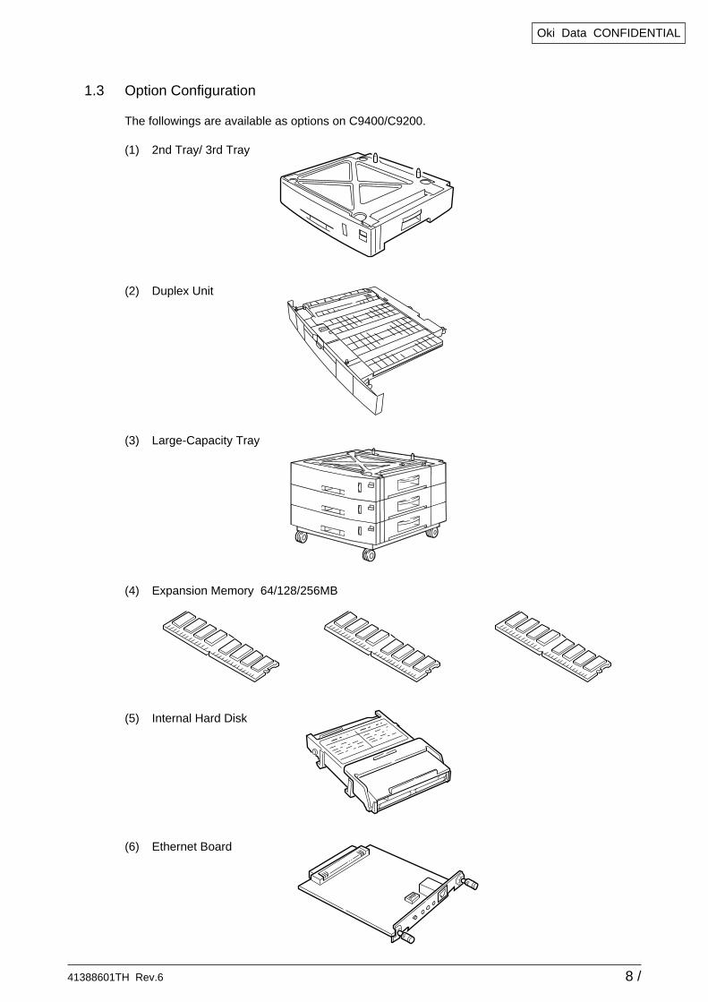
1.3 Option Configuration
The followings are available as options on C9400/C9200.
(1) 2nd Tray/ 3rd Tray
(2) Duplex Unit
(3) Large-Capacity Tray
(4) Expansion Memory 64/128/256MB
(5) Internal Hard Disk
(6) Ethernet Board
41388601TH Rev.6 9 /
Oki Data CONFIDENTIAL
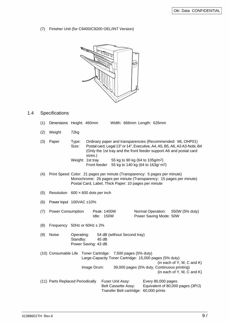
(7) Finisher Unit (for C9400/C9200 OEL/INT Version)
1.4 Specifications
(1) Dimensions Height: 460mm Width: 666mm Length: 626mm
(2) Weight 72kg
(3) Paper Type: Ordinary paper and transparencies (Recommended: ML OHP01)Size: Postal card, Legal 13" or 14", Executive, A4, A5, B5, A6, A3 A3-Nobi, B4
(Only the 1st tray and the front feeder support A6 and postal cardsizes.)
Weight: 1st tray 55 kg to 90 kg (64 to 105g/m2)Front feeder 55 kg to 140 kg (64 to 163g/ m2)
(4) Print Speed Color: 21 pages per minute (Transparency: 5 pages per minute)Monochrome: 26 pages per minute (Transparency: 15 pages per minute)Postal Card, Label, Thick Paper: 10 pages per minute
(5) Resolution 600 × 600 dots per inch
(6) Power Input 100VAC ±10%
(7) Power Consumption Peak: 1400W Normal Operation: 550W (5% duty)Idle: 150W Power Saving Mode: 50W
(8) Frequency 50Hz or 60Hz ± 2%
(9) Noise Operating: 54 dB (without Second tray)Standby: 45 dBPower Saving: 43 dB
(10) Consumable Life Toner Cartridge: 7,500 pages (5% duty)Large-Capacity Toner Cartridge: 15,000 pages (5% duty)
(in each of Y, M, C and K)Image Drum: 39,000 pages (5% duty, Continuous printing)
(in each of Y, M, C and K)
(11) Parts Replaced Periodically Fuser Unit Assy: Every 80,000 pagesBelt Cassette Assy: Equivalent of 80,000 pages (3P/J)Transfer Belt cartridge: 60,000 prints
41388601TH Rev.6 10 /
Oki Data CONFIDENTIAL
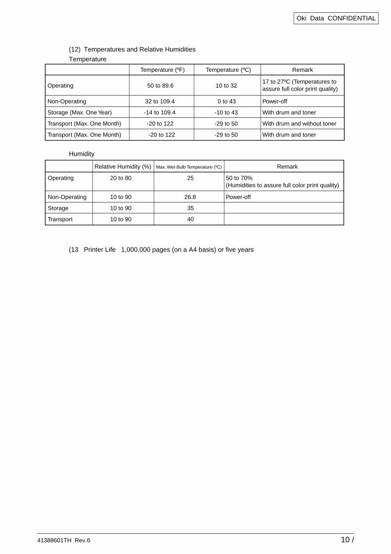
Temperature (ºF) RemarkTemperature (ºC)
Operating 50 to 89.6 10 to 3217 to 27ºC (Temperatures to assure full color print quality)
Non-Operating 32 to 109.4 0 to 43 Power-off
Storage (Max. One Year) -14 to 109.4 -10 to 43 With drum and toner
Transport (Max. One Month) -20 to 122 -29 to 50 With drum and without toner
Transport (Max. One Month) -20 to 122 -29 to 50 With drum and toner
Relative Humidity (%) Max. Wet-Bulb Temperature (ºC) Remark
Operating 20 to 80 25 50 to 70%(Humidities to assure full color print quality)
Non-Operating 10 to 90 26.8 Power-off
Storage 10 to 90 35
Transport 10 to 90 40
(12) Temperatures and Relative Humidities
Temperature
Humidity
(13 Printer Life 1,000,000 pages (on a A4 basis) or five years
41388601TH Rev.6 11 /
Oki Data CONFIDENTIAL
2. PARTS REPLACEMENT
This section describes the procedure for replacing the parts, assemblies and units in the field. Thereplacing procedure is given for detachment. To attach, use the reverse procedure.
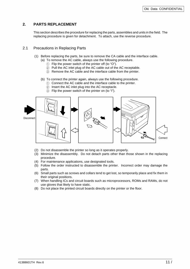
2.1 Precautions in Replacing Parts
(1) Before replacing the parts, be sure to remove the CA cable and the interface cable.(a) To remove the AC cable, always use the following procedure.1 Flip the power switch of the printer off (to “O”).2 Pull the AC inlet plug of the AC cable out of the AC receptable.3 Remove the AC cable and the interface cable from the printer.
(b) To connect the printer again, always use the following procedure.1 Connect the AC cable and the interface cable to the printer.2 Insert the AC inlet plug into the AC receptacle.3 Flip the power switch of the printer on (to “I”).
(2) Do not disassemble the printer so long as it operates properly.(3) Minimize the disassembly. Do not detach parts other than those shown in the replacing
procedure.(4) For maintenance applications, use designated tools.(5) Follow the order instructed to disassemble the printer. Incorrect order may damage the
parts.(6) Small parts such as screws and collars tend to get lost, so temporarily place and fix them in
their original positions.(7) When handling ICs and circuit boards such as microprocessors, ROMs and RAMs, do not
use gloves that likely to have static.(8) Do not place the printed circuit boards directly on the printer or the floor.
Disconnect
Connect
41388601TH Rev.6 12 /
Oki Data CONFIDENTIAL
No.
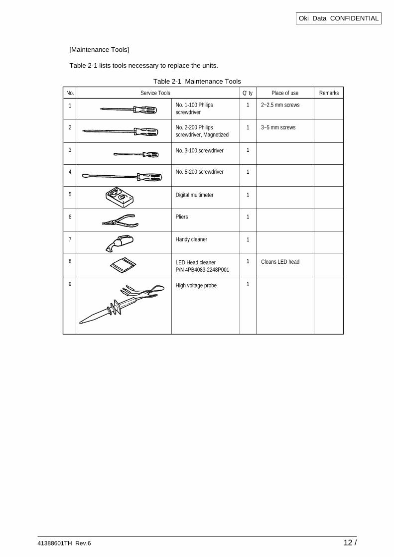
No. 1-100 Philipsscrewdriver
Q' ty Place of use RemarksService Tools
1
2
3
4
5
6
8
No. 2-200 Philipsscrewdriver, Magnetized
No. 3-100 screwdriver
No. 5-200 screwdriver
Digital multimeter
Pliers
Handy cleaner
LED Head cleanerP/N 4PB4083-2248P001
1
1
1
1
1
1
1
2~2.5 mm screws
3~5 mm screws
Cleans LED head
9 High voltage probe 1
7 1
[Maintenance Tools]
Table 2-1 lists tools necessary to replace the units.
Table 2-1 Maintenance Tools

41388601TH Rev.6 13 /
Oki Data CONFIDENTIAL
2.2 Parts Layout
Figure 2.1
41388601TH Rev.6 14 /
Oki Data CONFIDENTIAL
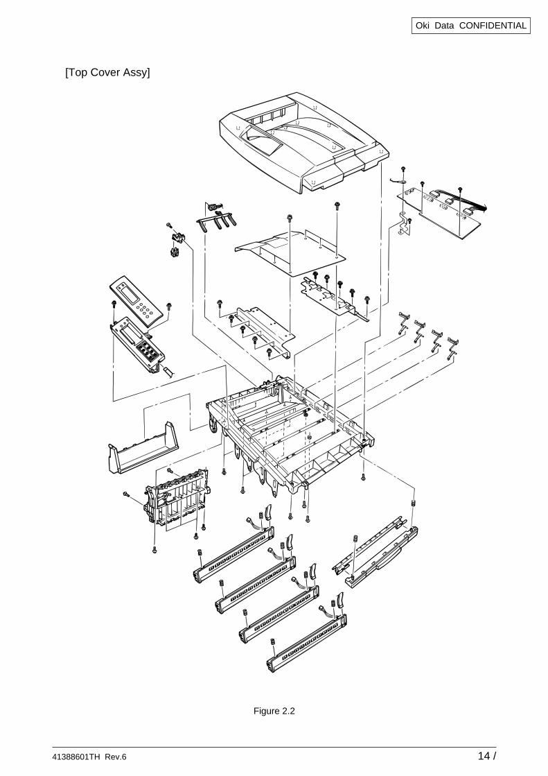
Figure 2.2
[Top Cover Assy]
41388601TH Rev.6 15 /
Oki Data CONFIDENTIAL
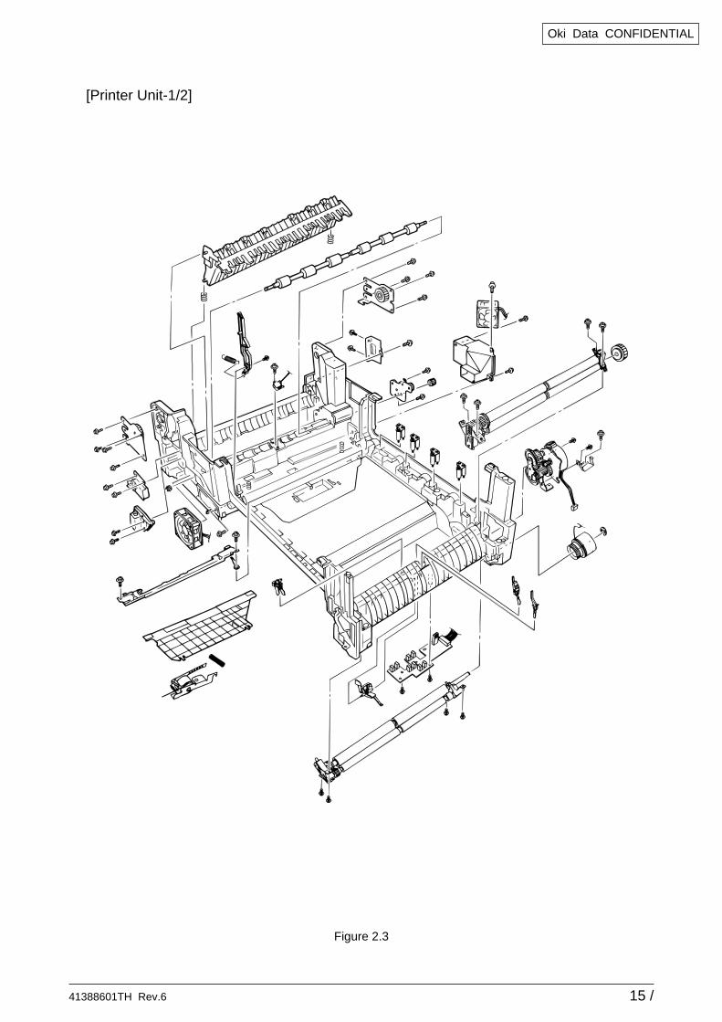
Figure 2.3
[Printer Unit-1/2]
41388601TH Rev.6 16 /
Oki Data CONFIDENTIAL
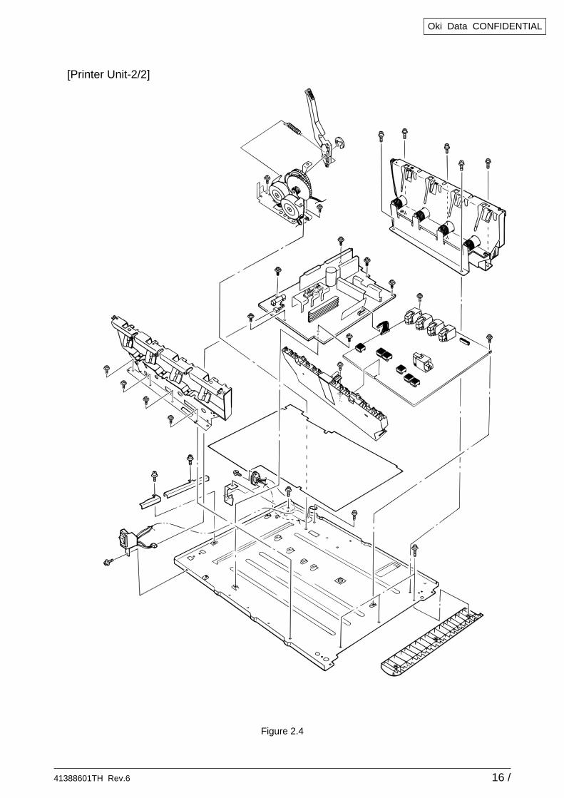
Figure 2.4
[Printer Unit-2/2]
41388601TH Rev.6 17 /
Oki Data CONFIDENTIAL
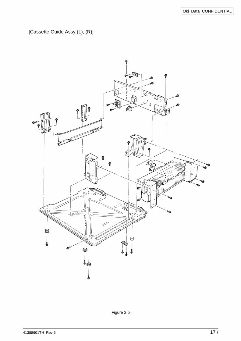
Figure 2.5
[Cassette Guide Assy (L), (R)]
41388601TH Rev.6 18 /
Oki Data CONFIDENTIAL
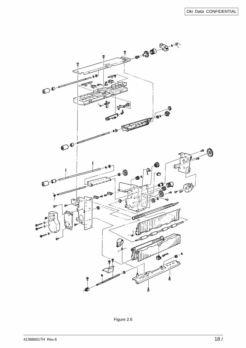
Figure 2.6
41388601TH Rev.6 19 /
Oki Data CONFIDENTIAL
AB
C
D
E
A
B
C
D
E
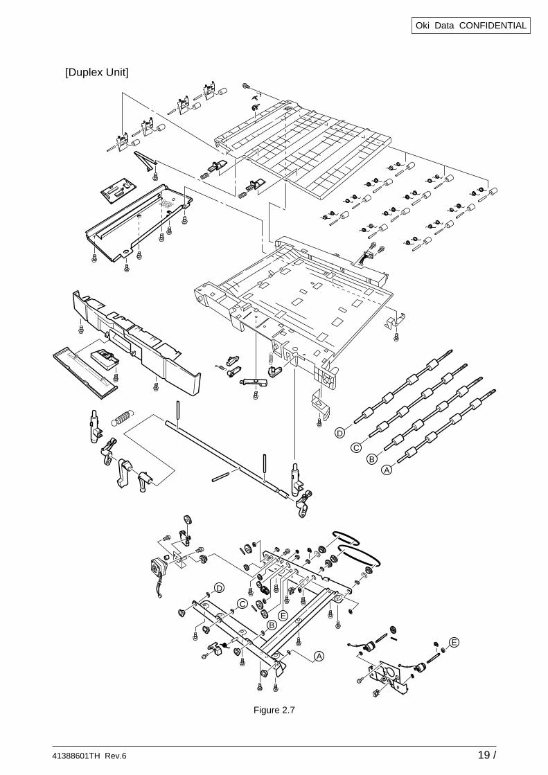
Figure 2.7
[Duplex Unit]
41388601TH Rev.6 20 /
Oki Data CONFIDENTIAL
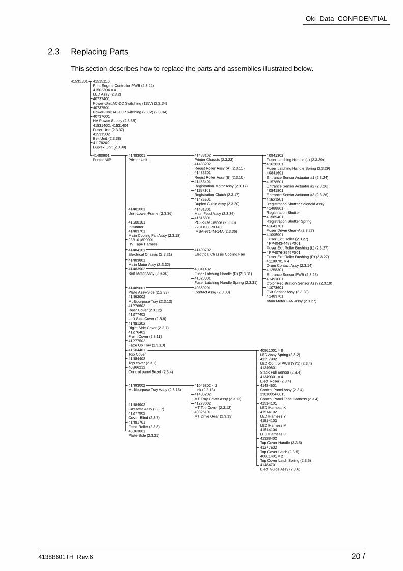
2.3 Replacing Parts
This section describes how to replace the parts and assemblies illustrated below.
41531301 41515110Print Engine Controller PWB (2.3.22)41502304 × 4LED Assy (2.3.2)40737401Power-Unit AC-DC Switching (115V) (2.3.34)40737501Power-Unit AC-DC Switching (230V) (2.3.34)40737601HV Power Supply (2.3.35)41531402, 41531404Fuser Unit (2.3.37)41531502Belt Unit (2.3.38)41178202Duplex Unit (2.3.39)
41483001Printer Unit
41500101Insurator41483701Main Cooling Fan Assy (2.3.18)2381018P0001HV Tape Harness
41480901Printer NIP
41483102Printer Chassis (2.3.23)41483202Regist Roller Assy (A) (2.3.15)41483301Regist Roller Assy (B) (2.3.16)41483401Registration Motor Assy (2.3.17)41187101Registration Clutch (2.3.17)41486601Duplex Guide Assy (2.3.20)
41045802 × 2Link (2.3.13)41486202MT Tray Cover Assy (2.3.13)41278002MT Top Cover (2.3.13)40325101MT Drive Gear (2.3.13)
41493002Multipurpose Tray Assy (2.3.13)
41481301Main Feed Assy (2.3.36)41515801PCE-Size Sence (2.3.36)22011000P0140IMSA-9714N-14A (2.3.36)
41481001Unit-Lower-Frame (2.3.36)
41484902Cassette Assy (2.3.7)41277902Cover-Blind (2.3.7)41481701Feed-Roller (2.3.8)40863801Plate-Side (2.3.21)
40850201Contact Assy (2.3.33)
40841302Fuser Latching Handle (L) (2.3.29)41628301Fuser Latching Handle Spring (2.3.29)40841601Entrance Sensor Actuator #1 (2.3.24)41578501Entrance Sensor Actuator #2 (2.3.26)40841801Entrance Sensor Actuator #3 (2.3.26)41621801Registration Shutter Solenoid Assy41488801Registration Shutter41589401Registration Shutter Spring41641701Fuser Driver Gear-A (2.3.27)41095901Fuser Exit Roller (2.3.27)4PP4043-4489P001Fuser Exit Roller Bushing (L) (2.3.27)4PP4076-3949P001Fuser Exit Roller Bushing (R) (2.3.27)41189701 × 4Drum Contact Assy (2.3.14)41258301Entrance Sensor PWB (2.3.25)41491001Color Registration Sensor Assy (2.3.19)41073601Exit Sensor Assy (2.3.28)41483701Main Motor FAN Assy (2.3.27)
40861001 × 8LED Assy Spring (2.3.2)41257902LED Control PWB (Y71) (2.3.4)41349801Stack Full Sensor (2.3.4)41349301 × 4Eject Roller (2.3.4)41484501Control Panel Assy (2.3.4)2381005P0015Control Panel Tape Harness (2.3.4)41514101LED Harness K41514102LED Harness Y 41514103LED Harness M 41514104LED Harness C 41328402Top Cover Handle (2.3.5)41277602Top Cover Latch (2.3.5)40861401 × 2Top Cover Latch Spring (2.3.5)41484701Eject Guide Assy (2.3.6)
41489001Plate Assy-Side (2.3.33)41493002Multipurpose Tray (2.3.13)41276502Rear Cover (2.3.12)41277402Left Side Cover (2.3.9)41481202Right Side Cover (2.3.7)41276402Front Cover (2.3.11)41277502Face Up Tray (2.3.10)41504401Top Cover41484402Top cover (2.3.1)40866212Control panel Bezel (2.3.4)
41490702Electrical Chassis Cooling Fan
41484101Electrical Chassis (2.3.21)
41483801Main Motor Assy (2.3.32)41483902Belt Motor Assy (2.3.30)
40841402Fuser Latching Handle (R) (2.3.31)41628301Fuser Latching Handle Spring (2.3.31)
41388601TH Rev.6 21 /
Oki Data CONFIDENTIAL
2
1
1
1
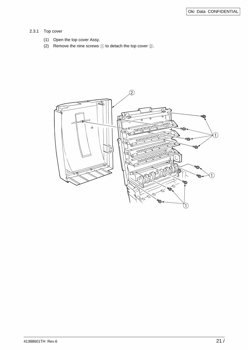
2.3.1 Top cover
(1) Open the top cover Assy.
(2) Remove the nine screws 1 to detach the top cover 2.
41388601TH Rev.6 22 /
Oki Data CONFIDENTIAL
1
3
4
4
3
2
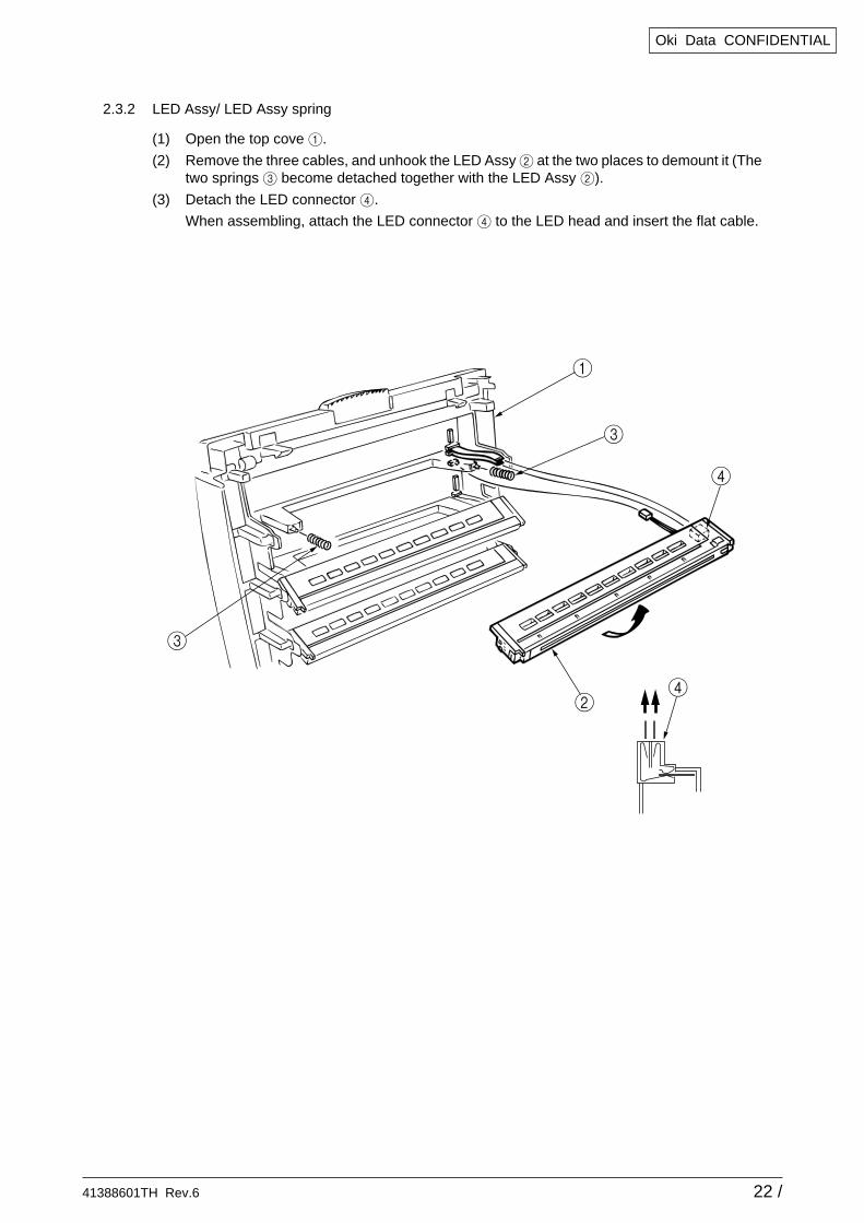
2.3.2 LED Assy/ LED Assy spring
(1) Open the top cove 1.
(2) Remove the three cables, and unhook the LED Assy 2 at the two places to demount it (Thetwo springs 3 become detached together with the LED Assy 2).
(3) Detach the LED connector 4.
When assembling, attach the LED connector 4 to the LED head and insert the flat cable.
41388601TH Rev.6 23 /
Oki Data CONFIDENTIAL
8
4
17
6
31
5
2
2
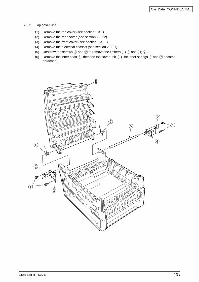
2.3.3 Top cover unit
(1) Remove the top cover (see section 2.3.1).
(2) Remove the rear cover (see section 2.3.12).
(3) Remove the front cover (see section 2.3.11).
(4) Remove the electrical chassis (see section 2.3.21).
(5) Unscrew the screws 1 and 2 to remove the limiters (F) 3 and (R) 4.
(6) Remove the inner shaft 5, then the top cover unit 8 (The inner springs 6 and 7 becomedetached).
41388601TH Rev.6 24 /
Oki Data CONFIDENTIAL
7
621
4
C
0
99
AB
3
2
D
8
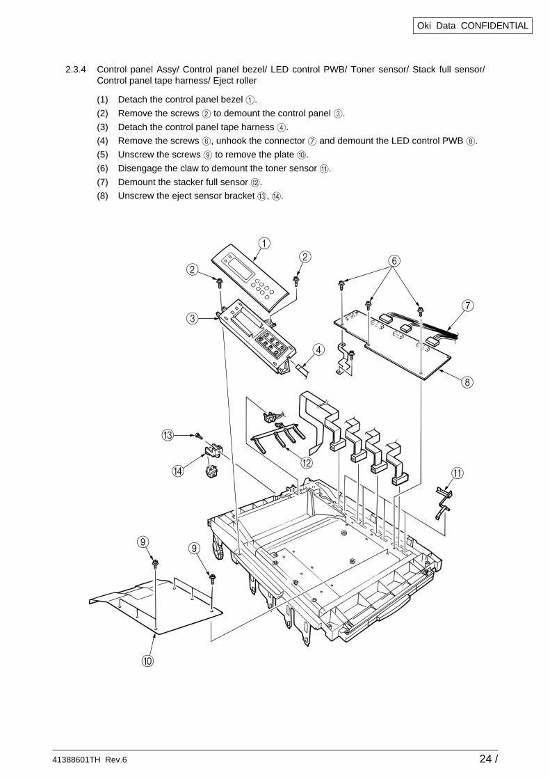
2.3.4 Control panel Assy/ Control panel bezel/ LED control PWB/ Toner sensor/ Stack full sensor/Control panel tape harness/ Eject roller
(1) Detach the control panel bezel 1.
(2) Remove the screws 2 to demount the control panel 3.
(3) Detach the control panel tape harness 4.
(4) Remove the screws 6, unhook the connector 7 and demount the LED control PWB 8.
(5) Unscrew the screws 9 to remove the plate 0.
(6) Disengage the claw to demount the toner sensor A.
(7) Demount the stacker full sensor B.
(8) Unscrew the eject sensor bracket C, D.
41388601TH Rev.6 25 /
Oki Data CONFIDENTIAL
3
1
1
2
4
4
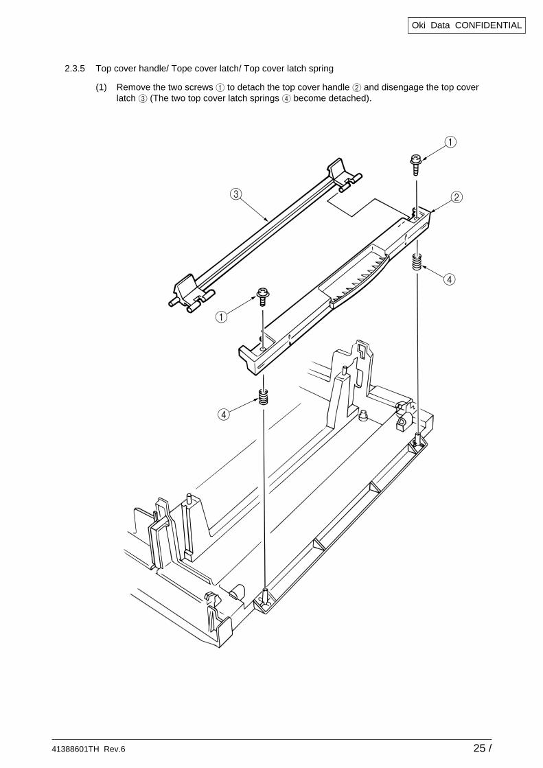
2.3.5 Top cover handle/ Tope cover latch/ Top cover latch spring
(1) Remove the two screws 1 to detach the top cover handle 2 and disengage the top coverlatch 3 (The two top cover latch springs 4 become detached).
41388601TH Rev.6 26 /
Oki Data CONFIDENTIAL
1 1
11
2
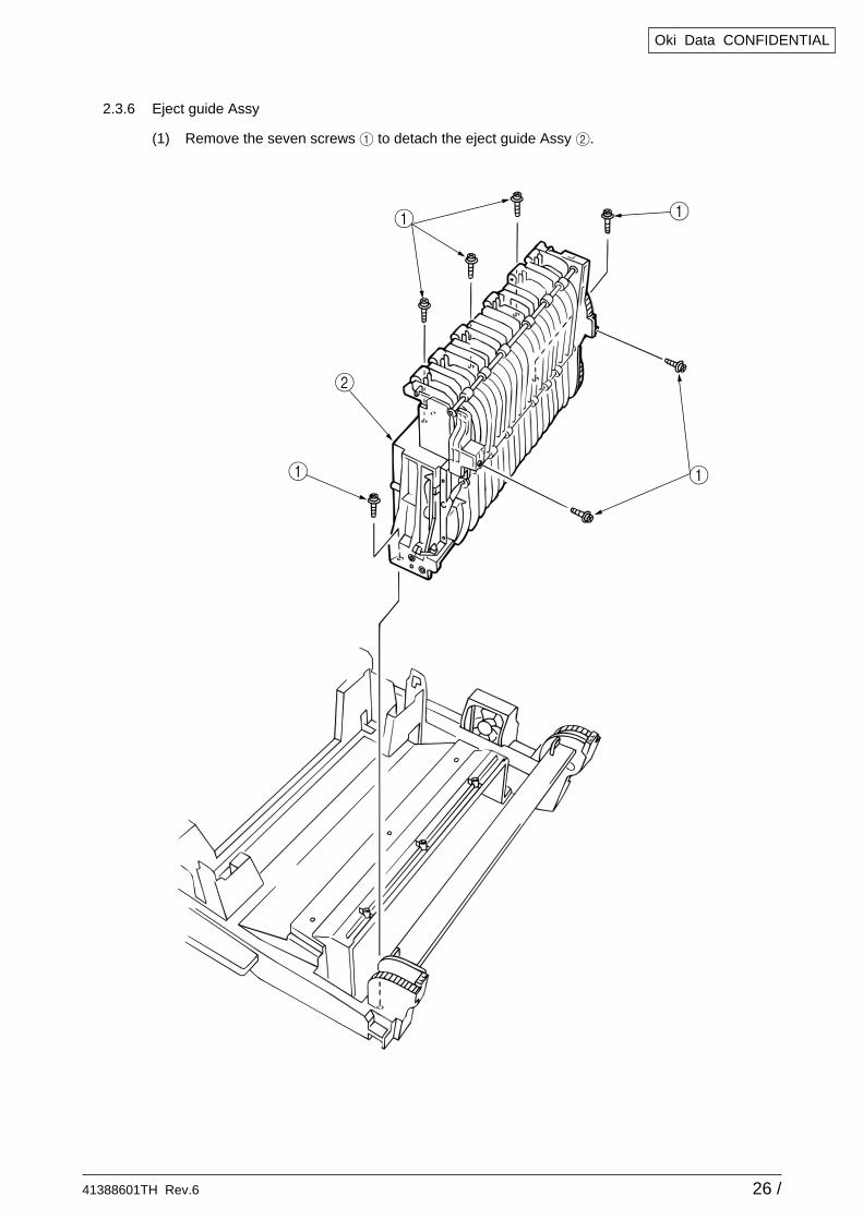
2.3.6 Eject guide Assy
(1) Remove the seven screws 1 to detach the eject guide Assy 2.
41388601TH Rev.6 27 /
Oki Data CONFIDENTIAL
5
4
2
1
5
3
5
5
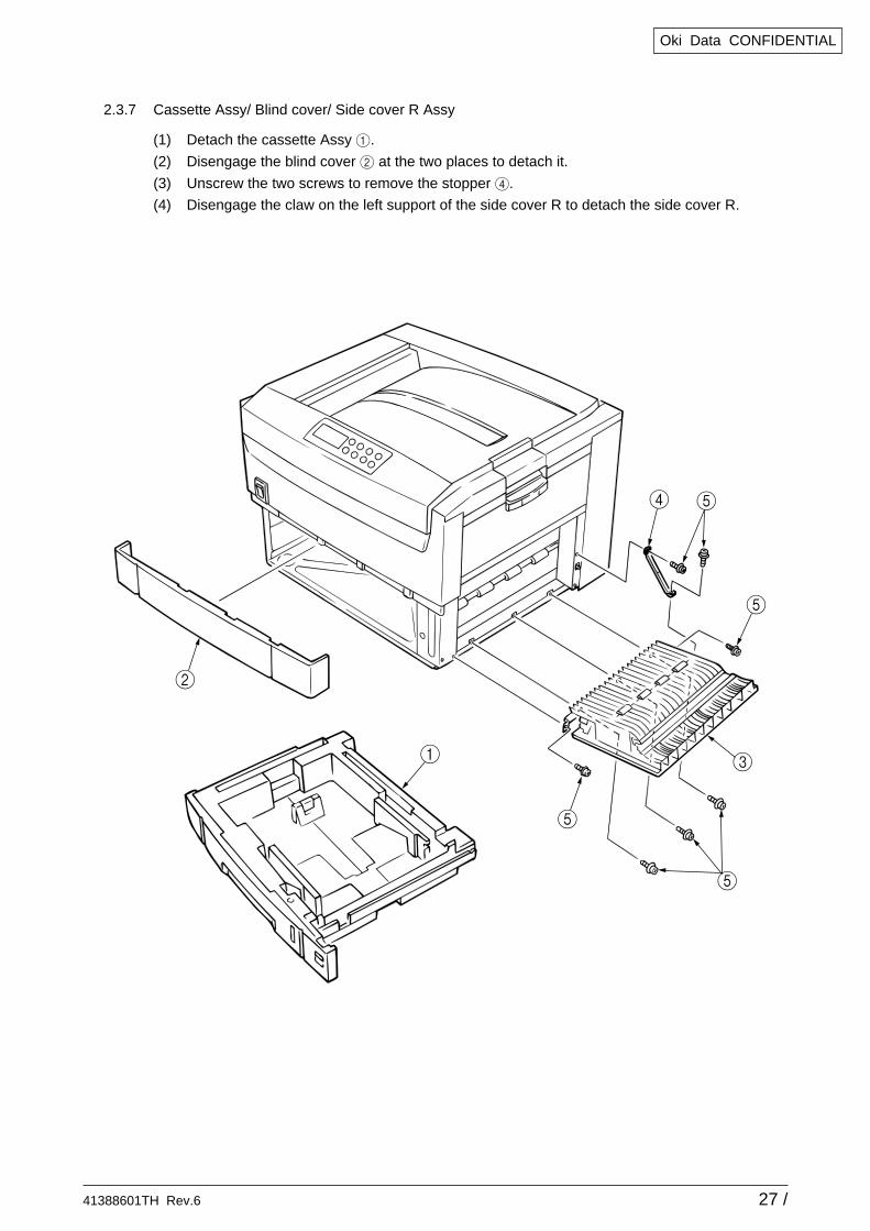
2.3.7 Cassette Assy/ Blind cover/ Side cover R Assy
(1) Detach the cassette Assy 1.
(2) Disengage the blind cover 2 at the two places to detach it.
(3) Unscrew the two screws to remove the stopper 4.
(4) Disengage the claw on the left support of the side cover R to detach the side cover R.
41388601TH Rev.6 28 /
Oki Data CONFIDENTIAL
1
1
1
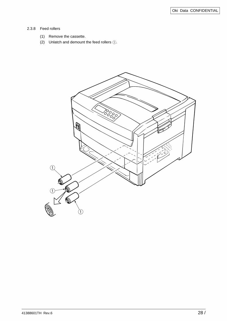
2.3.8 Feed rollers
(1) Remove the cassette.
(2) Unlatch and demount the feed rollers 1.
41388601TH Rev.6 29 /
Oki Data CONFIDENTIAL
1
1
2
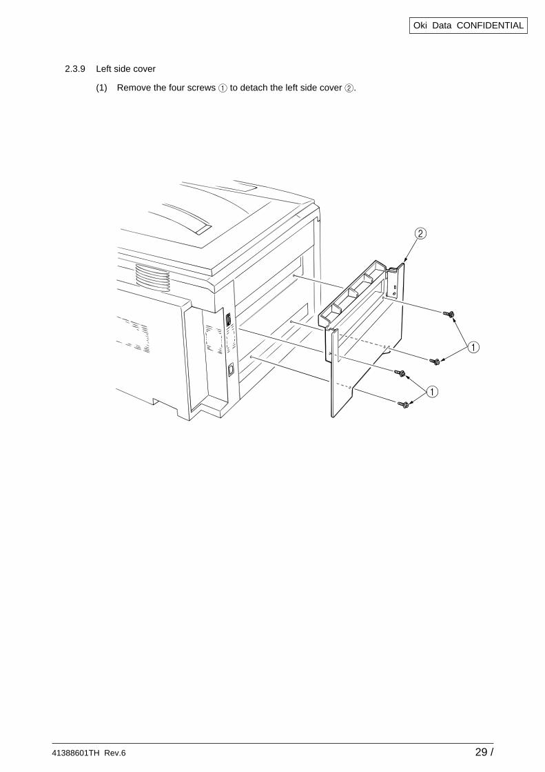
2.3.9 Left side cover
(1) Remove the four screws 1 to detach the left side cover 2.
41388601TH Rev.6 30 /
Oki Data CONFIDENTIAL
1
2
2
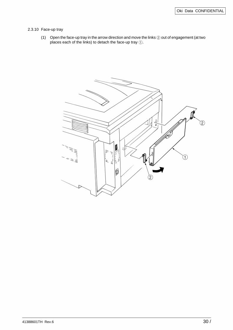
2.3.10 Face-up tray
(1) Open the face-up tray in the arrow direction and move the links 2 out of engagement (at twoplaces each of the links) to detach the face-up tray 1.
41388601TH Rev.6 31 /
Oki Data CONFIDENTIAL
4
4
2
34
4
4
1
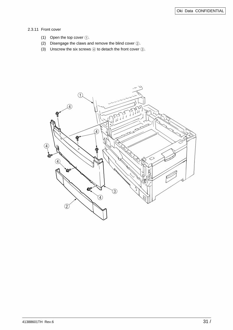
2.3.11 Front cover
(1) Open the top cover 1.
(2) Disengage the claws and remove the blind cover 2.
(3) Unscrew the six screws 4 to detach the front cover 3.
41388601TH Rev.6 32 /
Oki Data CONFIDENTIAL
1
2
4
3
3
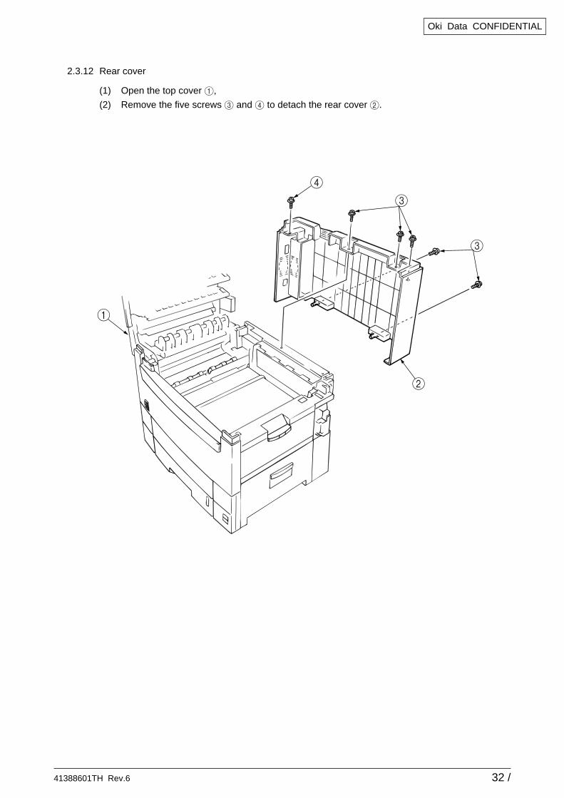
2.3.12 Rear cover
(1) Open the top cover 1,
(2) Remove the five screws 3 and 4 to detach the rear cover 2.
41388601TH Rev.6 33 /
Oki Data CONFIDENTIAL
1
2
3
6
5
6
4
5
Engagement
Engagement
8
3
81
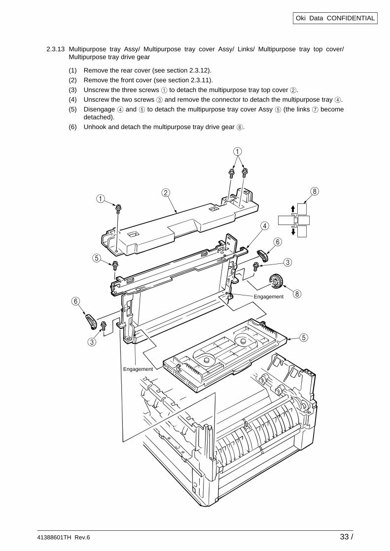
2.3.13 Multipurpose tray Assy/ Multipurpose tray cover Assy/ Links/ Multipurpose tray top cover/Multipurpose tray drive gear
(1) Remove the rear cover (see section 2.3.12).
(2) Remove the front cover (see section 2.3.11).
(3) Unscrew the three screws 1 to detach the multipurpose tray top cover 2.
(4) Unscrew the two screws 3 and remove the connector to detach the multipurpose tray 4.
(5) Disengage 4 and 5 to detach the multipurpose tray cover Assy 5 (the links 7 becomedetached).
(6) Unhook and detach the multipurpose tray drive gear 8.
41388601TH Rev.6 34 /
Oki Data CONFIDENTIAL
1
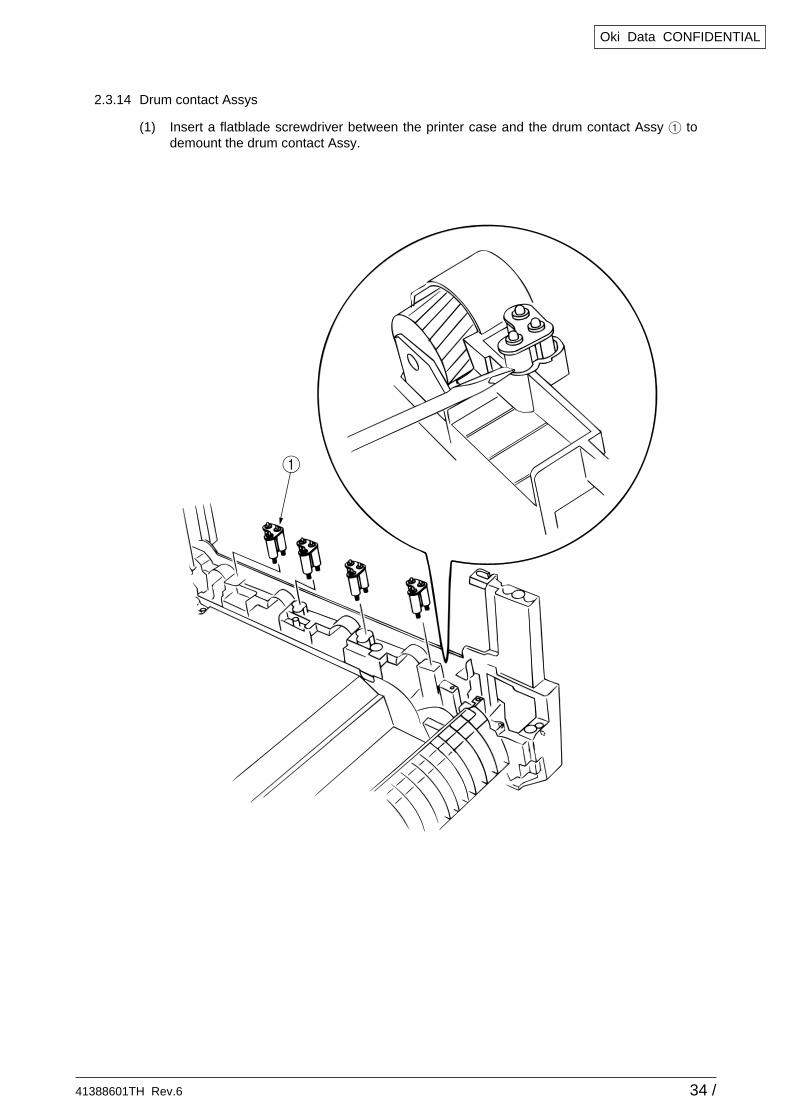
2.3.14 Drum contact Assys
(1) Insert a flatblade screwdriver between the printer case and the drum contact Assy 1 todemount the drum contact Assy.
41388601TH Rev.6 35 /
Oki Data CONFIDENTIAL
1
1
2
4 3
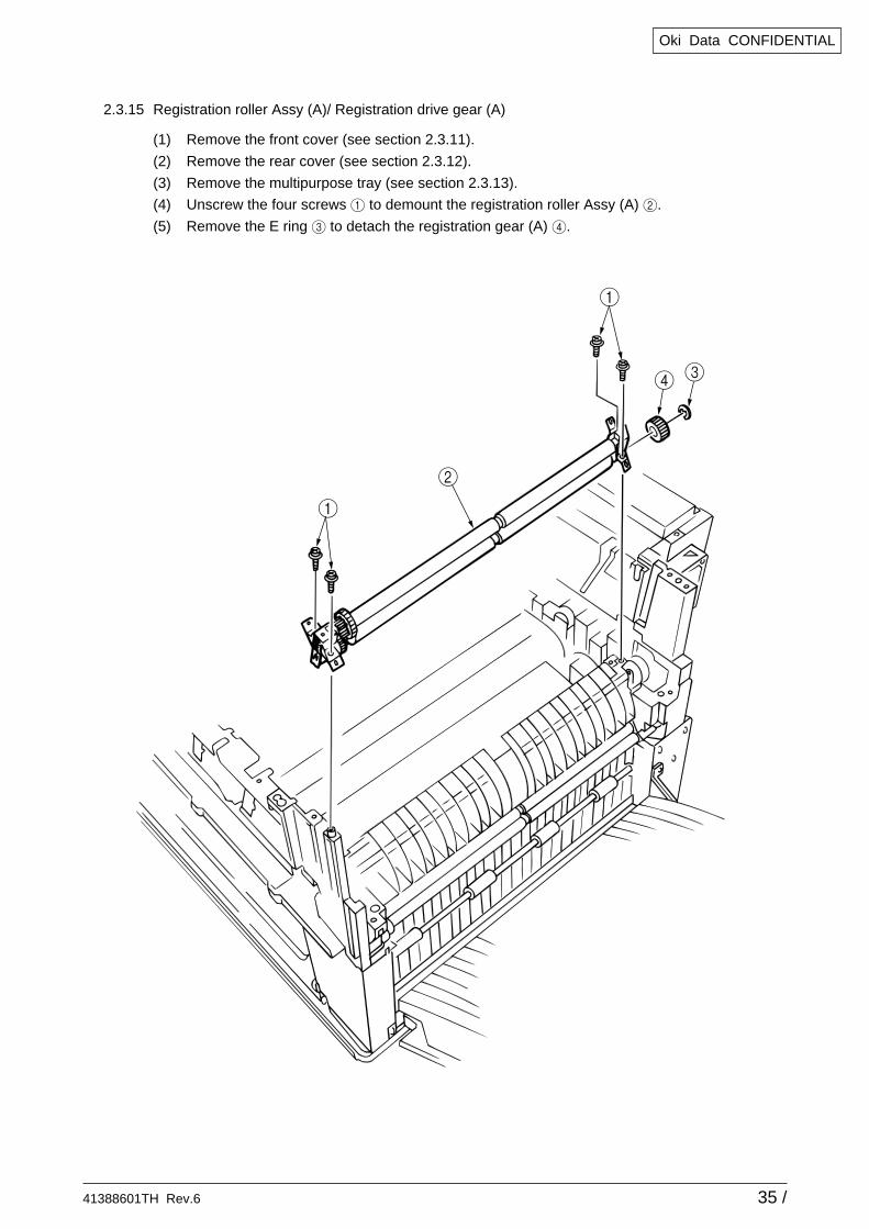
2.3.15 Registration roller Assy (A)/ Registration drive gear (A)
(1) Remove the front cover (see section 2.3.11).
(2) Remove the rear cover (see section 2.3.12).
(3) Remove the multipurpose tray (see section 2.3.13).
(4) Unscrew the four screws 1 to demount the registration roller Assy (A) 2.
(5) Remove the E ring 3 to detach the registration gear (A) 4.
41388601TH Rev.6 36 /
Oki Data CONFIDENTIAL
1
1
2
1
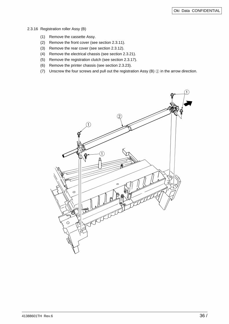
2.3.16 Registration roller Assy (B)
(1) Remove the cassette Assy.
(2) Remove the front cover (see section 2.3.11).
(3) Remove the rear cover (see section 2.3.12).
(4) Remove the electrical chassis (see section 2.3.21).
(5) Remove the registration clutch (see section 2.3.17).
(6) Remove the printer chassis (see section 2.3.23).
(7) Unscrew the four screws and pull out the registration Assy (B) 2 in the arrow direction.
41388601TH Rev.6 37 /
Oki Data CONFIDENTIAL
7 36
4
1
2
6
5
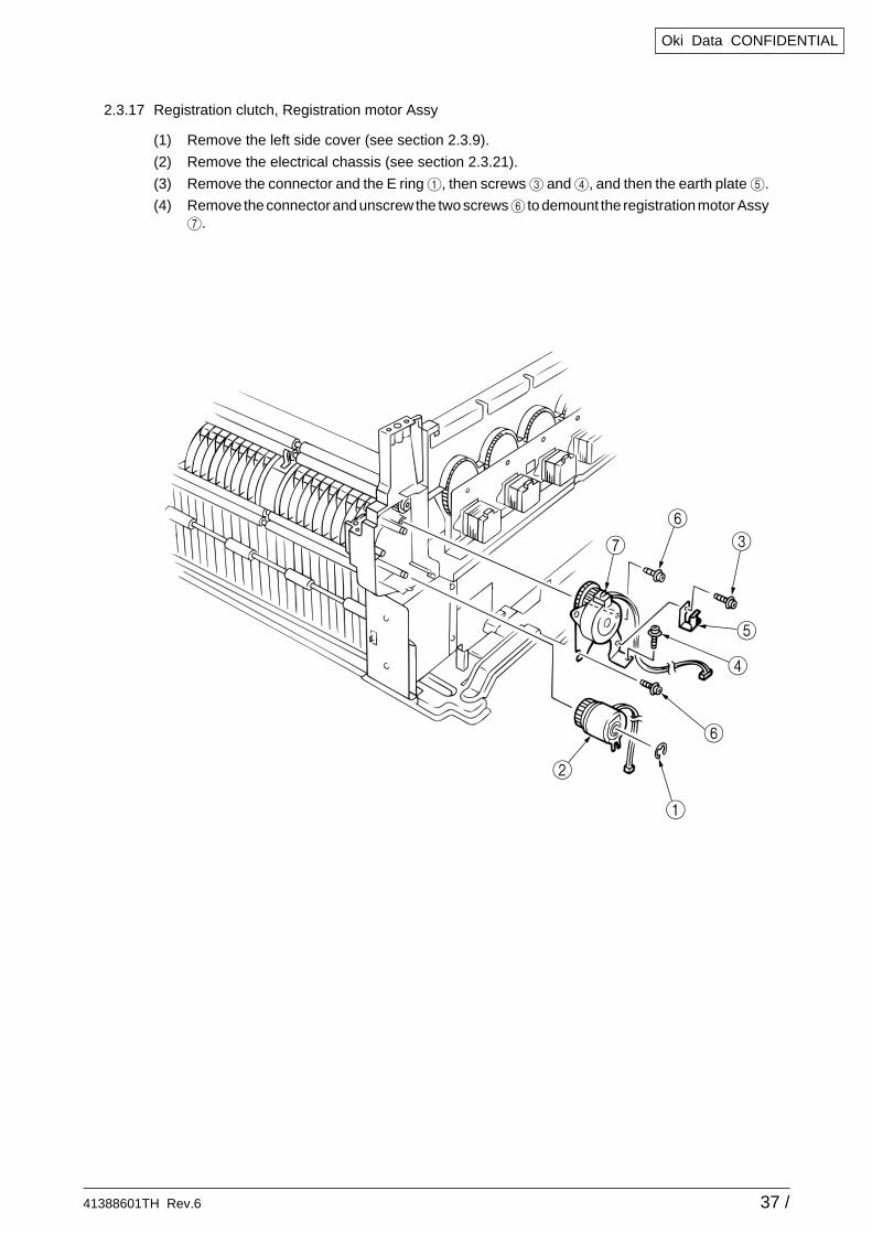
2.3.17 Registration clutch, Registration motor Assy
(1) Remove the left side cover (see section 2.3.9).
(2) Remove the electrical chassis (see section 2.3.21).
(3) Remove the connector and the E ring 1, then screws 3 and 4, and then the earth plate 5.
(4) Remove the connector and unscrew the two screws 6 to demount the registration motor Assy7.

41388601TH Rev.6 38 /
Oki Data CONFIDENTIAL
1
3
2
air direction
2.3.18 Cooling fan
(1) Unhook the connector 1, and remove the screws 2 and the cooling fan 3.
41388601TH Rev.6 39 /
Oki Data CONFIDENTIAL
1
1
3
4
1
2
2
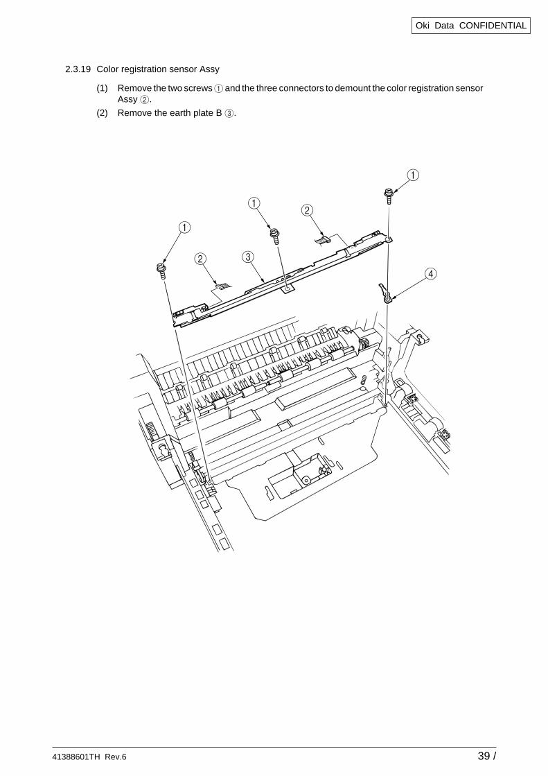
2.3.19 Color registration sensor Assy
(1) Remove the two screws 1 and the three connectors to demount the color registration sensorAssy 2.
(2) Remove the earth plate B 3.
41388601TH Rev.6 40 /
Oki Data CONFIDENTIAL
1
Main chassis (L side)
2
2
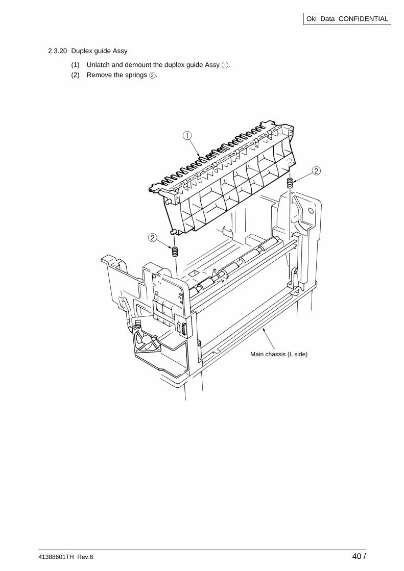
2.3.20 Duplex guide Assy
(1) Unlatch and demount the duplex guide Assy 1.
(2) Remove the springs 2.
41388601TH Rev.6 41 /
Oki Data CONFIDENTIAL
2
1
1
1
6
6
6
6
6
4
4
5
9
8
3
7
air direction
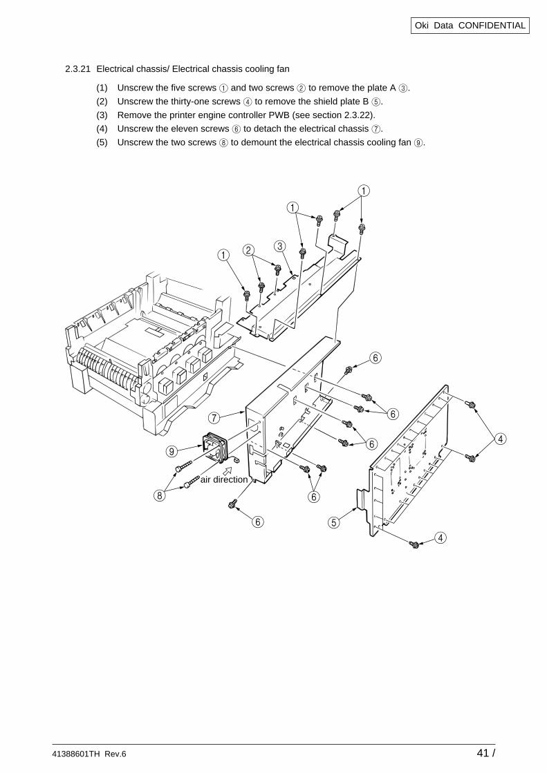
2.3.21 Electrical chassis/ Electrical chassis cooling fan
(1) Unscrew the five screws 1 and two screws 2 to remove the plate A 3.
(2) Unscrew the thirty-one screws 4 to remove the shield plate B 5.
(3) Remove the printer engine controller PWB (see section 2.3.22).
(4) Unscrew the eleven screws 6 to detach the electrical chassis 7.
(5) Unscrew the two screws 8 to demount the electrical chassis cooling fan 9.
41388601TH Rev.6 42 /
Oki Data CONFIDENTIAL
1
1
2
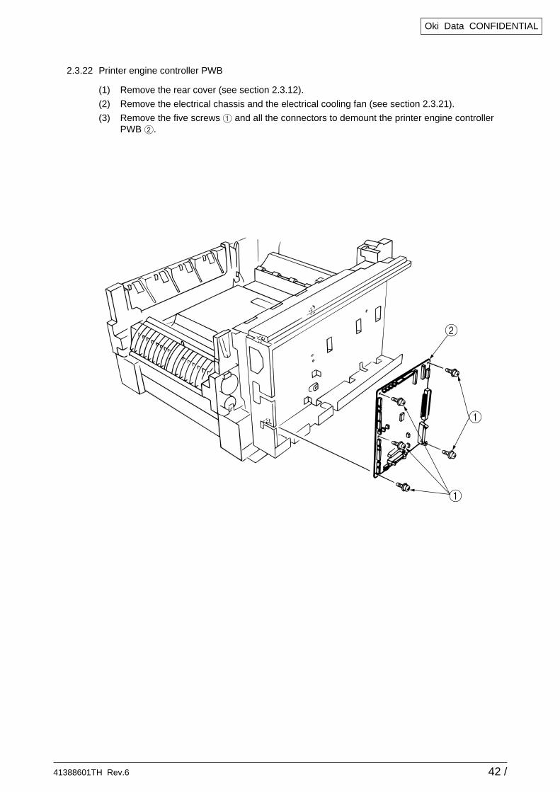
2.3.22 Printer engine controller PWB
(1) Remove the rear cover (see section 2.3.12).
(2) Remove the electrical chassis and the electrical cooling fan (see section 2.3.21).
(3) Remove the five screws 1 and all the connectors to demount the printer engine controllerPWB 2.
41388601TH Rev.6 43 /
Oki Data CONFIDENTIAL
4
4
4
3
3
4
3
4
5
1
2
3
3
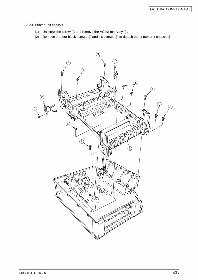
2.3.23 Printer unit chassis
(1) Unscrew the screw 1 and remove the AC switch Assy 2.
(2) Remove the four black screws 3 and six screws 4 to detach the printer unit chassis 5.

41388601TH Rev.6 44 /
Oki Data CONFIDENTIAL
1
Main chassis
2.3.24 Entrance cassette sensor actuator
(1) Remove the printer unit chassis (see section 2.3.12).
(2) Turn over the main chassis.
(3) Remove the two clamps with tweezers to demount the entrance cassette sensor actuator 1.
41388601TH Rev.6 45 /
Oki Data CONFIDENTIAL
1
2
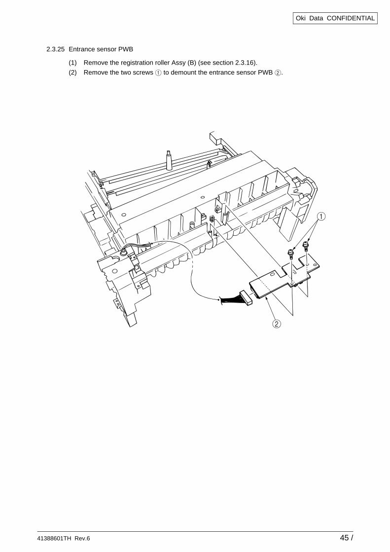
2.3.25 Entrance sensor PWB
(1) Remove the registration roller Assy (B) (see section 2.3.16).
(2) Remove the two screws 1 to demount the entrance sensor PWB 2.
41388601TH Rev.6 46 /
Oki Data CONFIDENTIAL
2
1
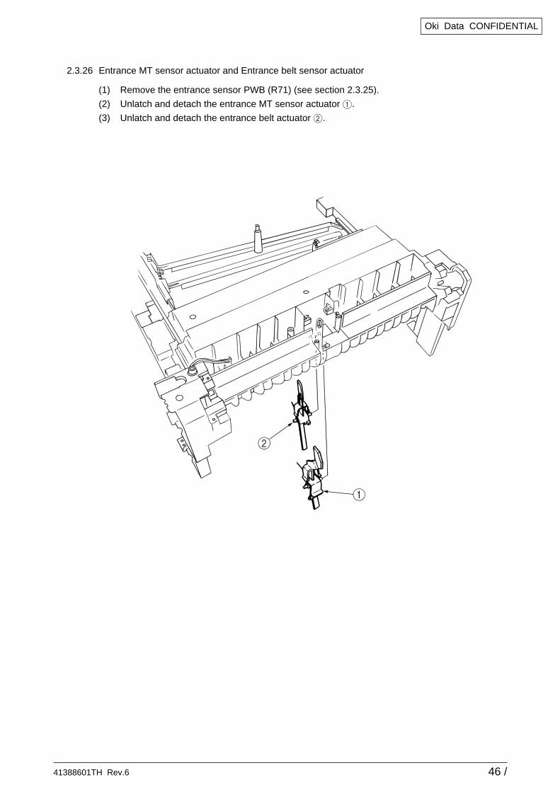
2.3.26 Entrance MT sensor actuator and Entrance belt sensor actuator
(1) Remove the entrance sensor PWB (R71) (see section 2.3.25).
(2) Unlatch and detach the entrance MT sensor actuator 1.
(3) Unlatch and detach the entrance belt actuator 2.
41388601TH Rev.6 47 /
Oki Data CONFIDENTIAL
B
0
0
A
9
9
5
7
1
8
43
1
2
C
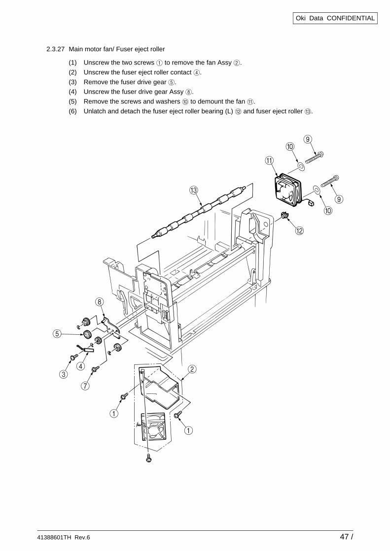
2.3.27 Main motor fan/ Fuser eject roller
(1) Unscrew the two screws 1 to remove the fan Assy 2.
(2) Unscrew the fuser eject roller contact 4.
(3) Remove the fuser drive gear 5.
(4) Unscrew the fuser drive gear Assy 8.
(5) Remove the screws and washers 0 to demount the fan A.
(6) Unlatch and detach the fuser eject roller bearing (L) B and fuser eject roller C.
41388601TH Rev.6 48 /
Oki Data CONFIDENTIAL
1
2
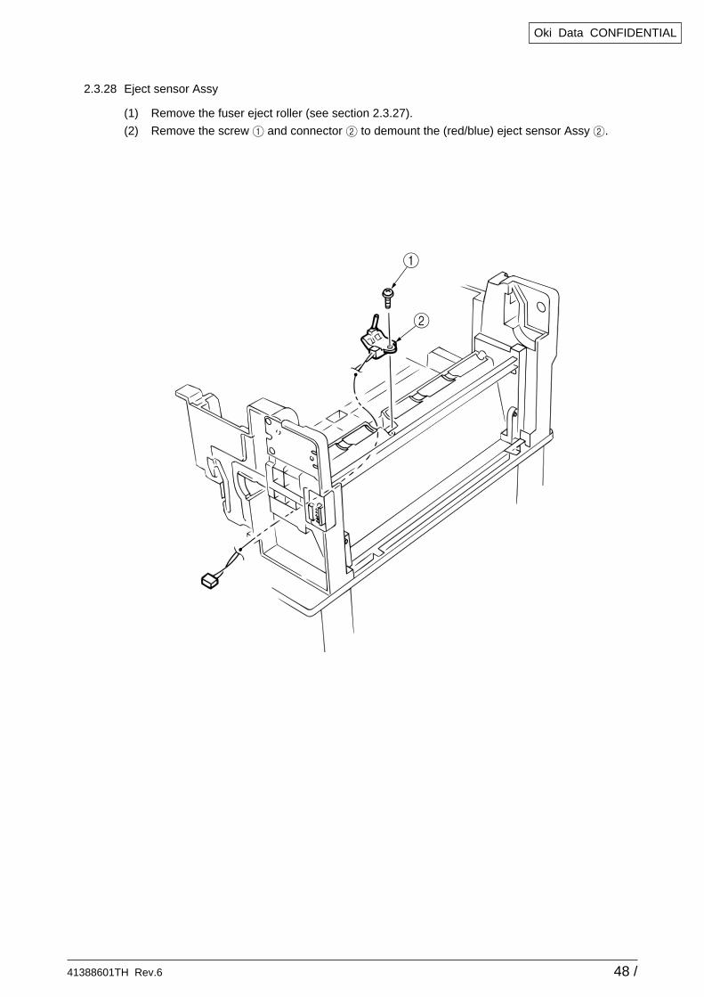
2.3.28 Eject sensor Assy
(1) Remove the fuser eject roller (see section 2.3.27).
(2) Remove the screw 1 and connector 2 to demount the (red/blue) eject sensor Assy 2.
41388601TH Rev.6 49 /
Oki Data CONFIDENTIAL
3
1
2
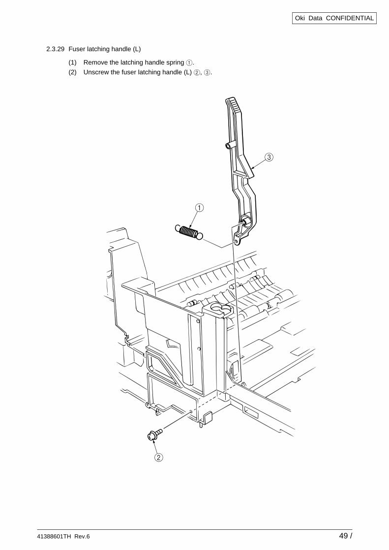
2.3.29 Fuser latching handle (L)
(1) Remove the latching handle spring 1.
(2) Unscrew the fuser latching handle (L) 2, 3.
41388601TH Rev.6 50 /
Oki Data CONFIDENTIAL
23
1
1
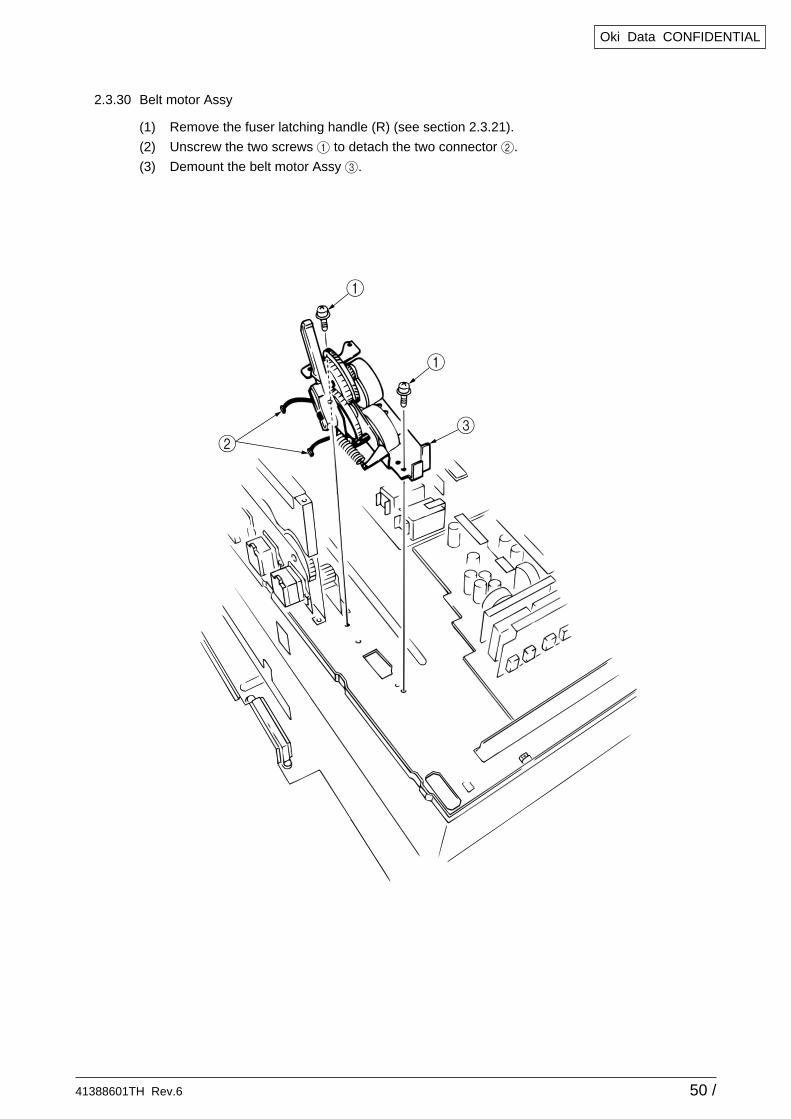
2.3.30 Belt motor Assy
(1) Remove the fuser latching handle (R) (see section 2.3.21).
(2) Unscrew the two screws 1 to detach the two connector 2.
(3) Demount the belt motor Assy 3.
41388601TH Rev.6 51 /
Oki Data CONFIDENTIAL
3
12
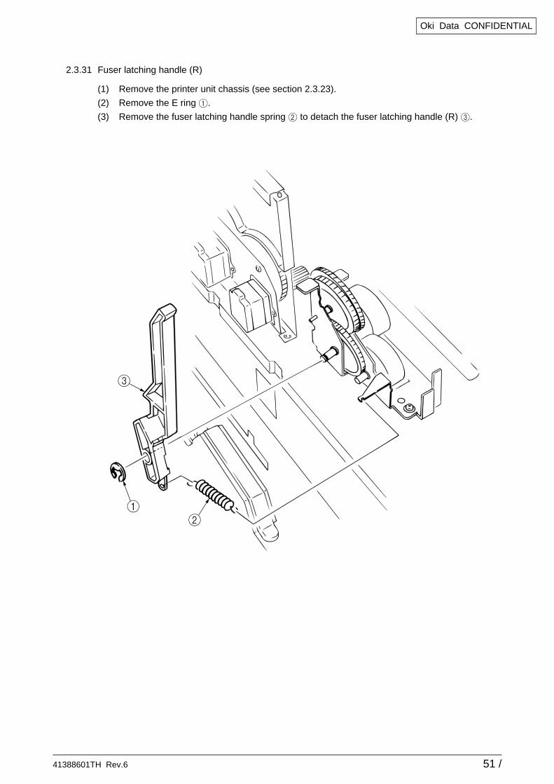
2.3.31 Fuser latching handle (R)
(1) Remove the printer unit chassis (see section 2.3.23).
(2) Remove the E ring 1.
(3) Remove the fuser latching handle spring 2 to detach the fuser latching handle (R) 3.
41388601TH Rev.6 52 /
Oki Data CONFIDENTIAL
1
2
1
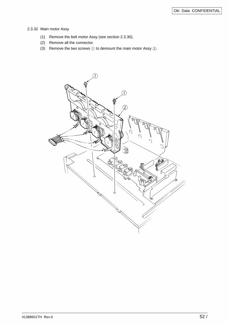
2.3.32 Main motor Assy
(1) Remove the belt motor Assy (see section 2.3.30).
(2) Remove all the connector.
(3) Remove the two screws 1 to demount the main motor Assy 2.
41388601TH Rev.6 53 /
Oki Data CONFIDENTIAL
4
2
1
3
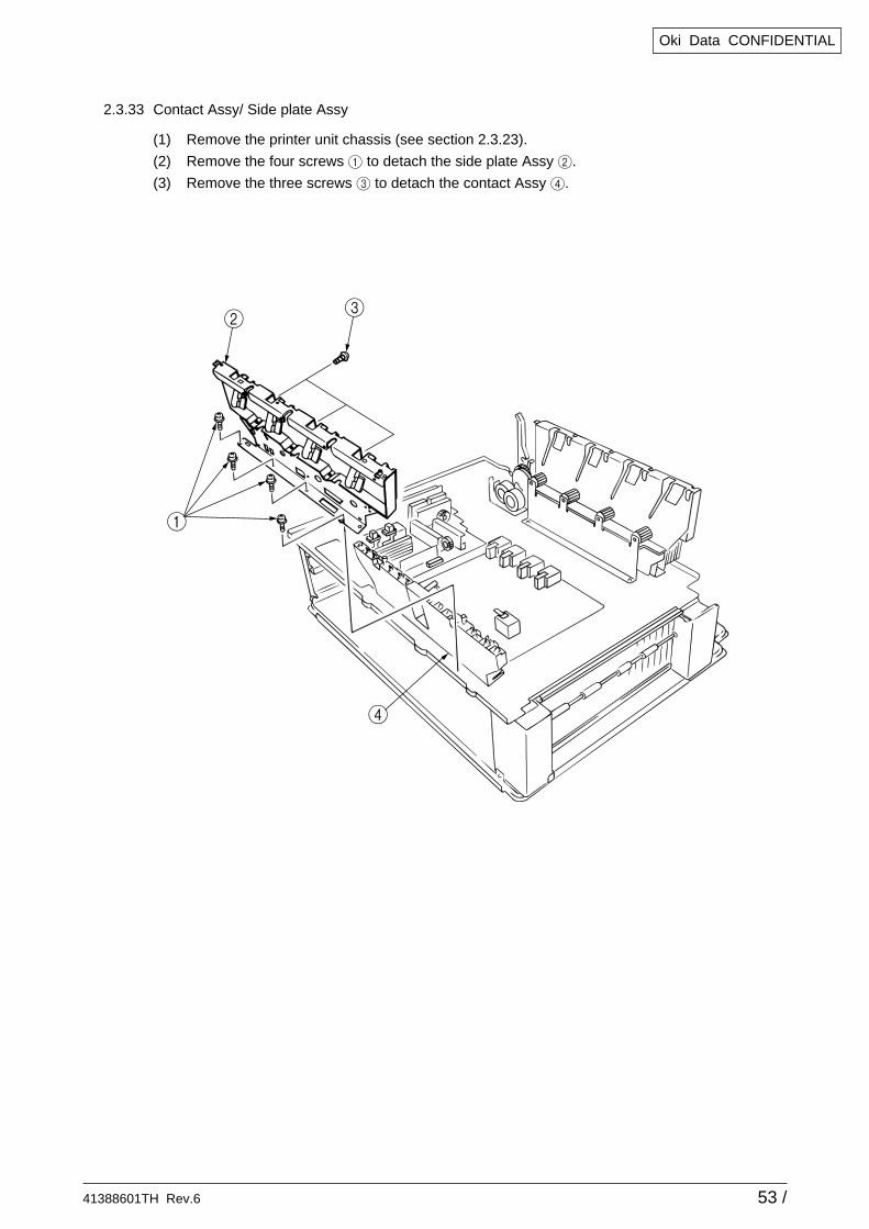
2.3.33 Contact Assy/ Side plate Assy
(1) Remove the printer unit chassis (see section 2.3.23).
(2) Remove the four screws 1 to detach the side plate Assy 2.
(3) Remove the three screws 3 to detach the contact Assy 4.
41388601TH Rev.6 54 /
Oki Data CONFIDENTIAL
1
3
8
A
27
6
5
0
9
0
0
2
2
B
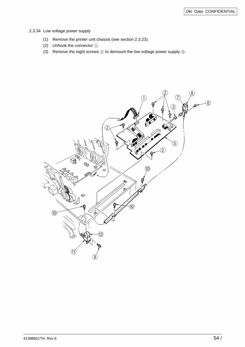
2.3.34 Low voltage power supply
(1) Remove the printer unit chassis (see section 2.3.23).
(2) Unhook the connector 1.
(3) Remove the eight screws 2 to demount the low voltage power supply 5.

41388601TH Rev.6 55 /
Oki Data CONFIDENTIAL
2
2
1
3
2.3.35 High voltage power supply
(1) Remove the contact Assy (see section 2.3.33).
(2) Unhook the connector of the high voltage power supply 1.
(3) Remove the two screws 2 to detach the high voltage power supply 1 and the tape harness3.
41388601TH Rev.6 56 /
Oki Data CONFIDENTIAL
8
3
3
6
7
5
1
9
0
1
4
2
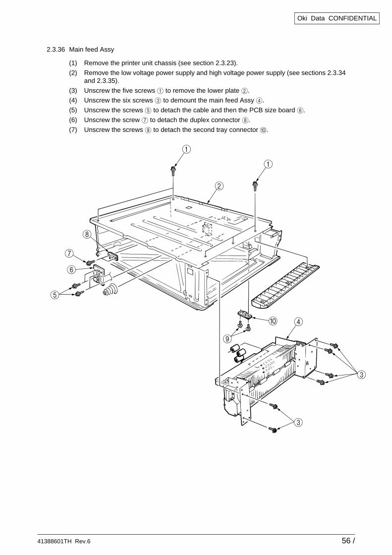
2.3.36 Main feed Assy
(1) Remove the printer unit chassis (see section 2.3.23).
(2) Remove the low voltage power supply and high voltage power supply (see sections 2.3.34and 2.3.35).
(3) Unscrew the five screws 1 to remove the lower plate 2.
(4) Unscrew the six screws 3 to demount the main feed Assy 4.
(5) Unscrew the screws 5 to detach the cable and then the PCB size board 6.
(6) Unscrew the screw 7 to detach the duplex connector 8.
(7) Unscrew the screws 9 to detach the second tray connector 0.
41388601TH Rev.6 57 /
Oki Data CONFIDENTIAL
3
2
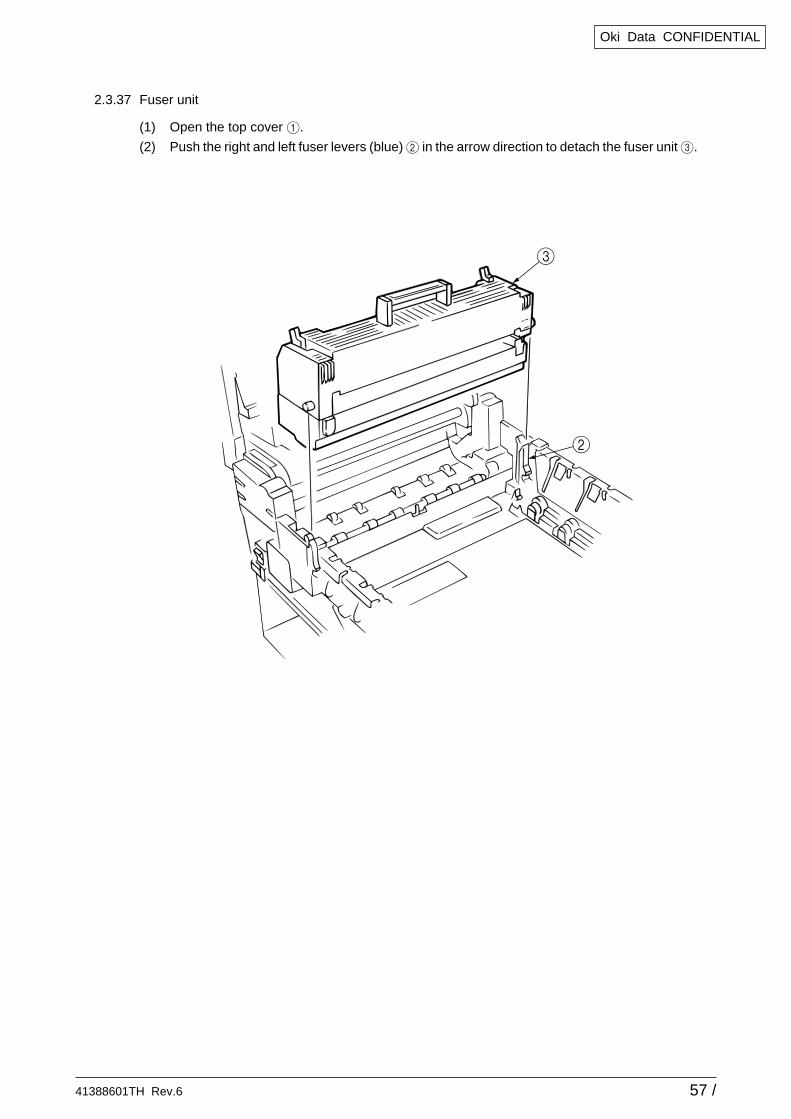
2.3.37 Fuser unit
(1) Open the top cover 1.
(2) Push the right and left fuser levers (blue) 2 in the arrow direction to detach the fuser unit 3.
41388601TH Rev.6 58 /
Oki Data CONFIDENTIAL
1
2
3
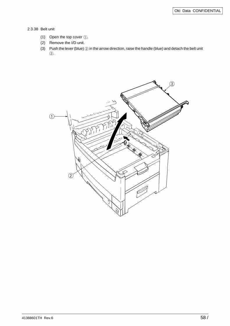
2.3.38 Belt unit
(1) Open the top cover 1.
(2) Remove the I/D unit.
(3) Push the lever (blue) 2 in the arrow direction, raise the handle (blue) and detach the belt unit3.
41388601TH Rev.6 59 /
Oki Data CONFIDENTIAL
132
5
4
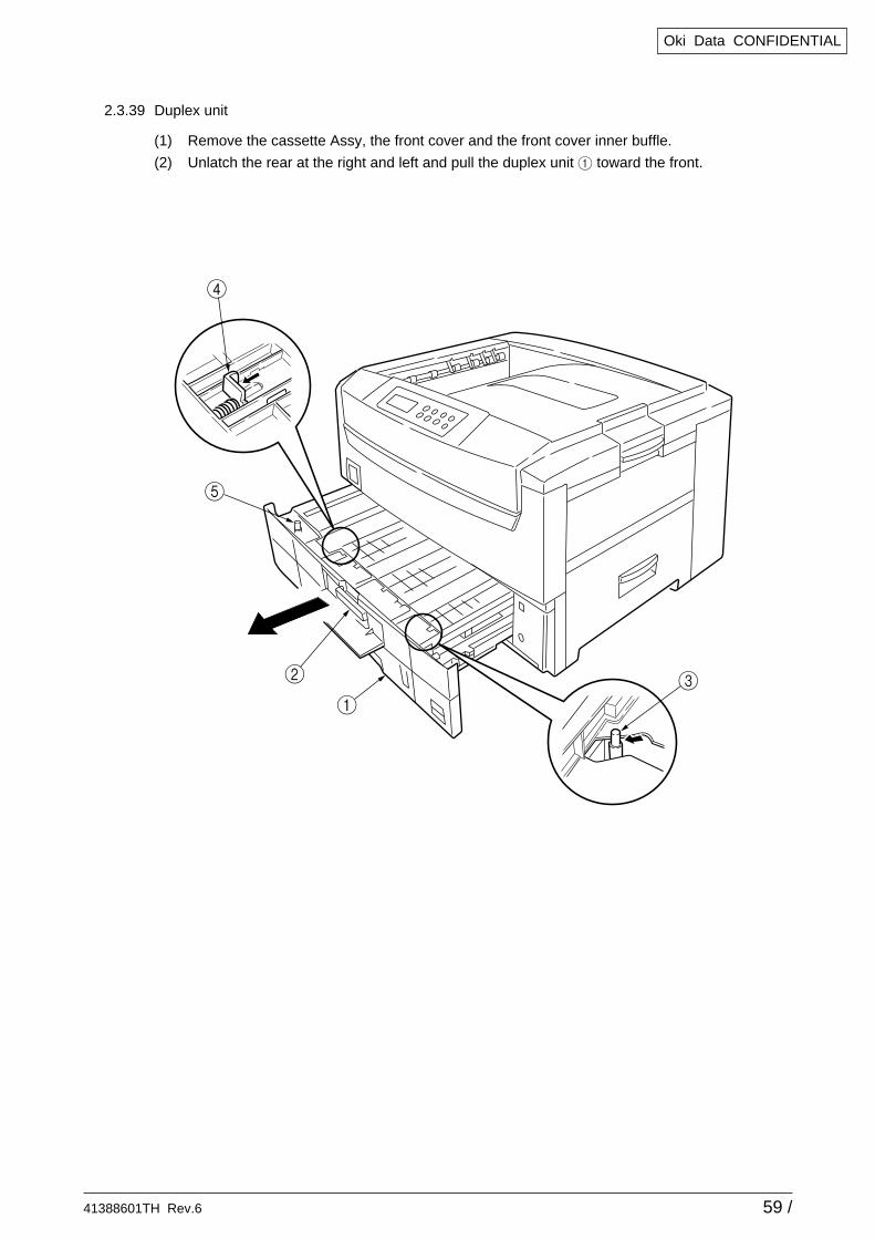
2.3.39 Duplex unit
(1) Remove the cassette Assy, the front cover and the front cover inner buffle.
(2) Unlatch the rear at the right and left and pull the duplex unit 1 toward the front.
41388601TH Rev.6 60 /
Oki Data CONFIDENTIAL
1
1
3
5
4
2
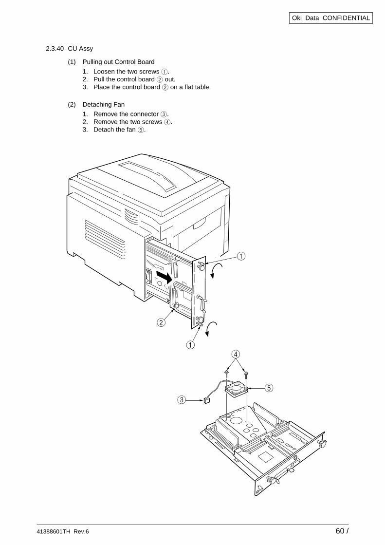
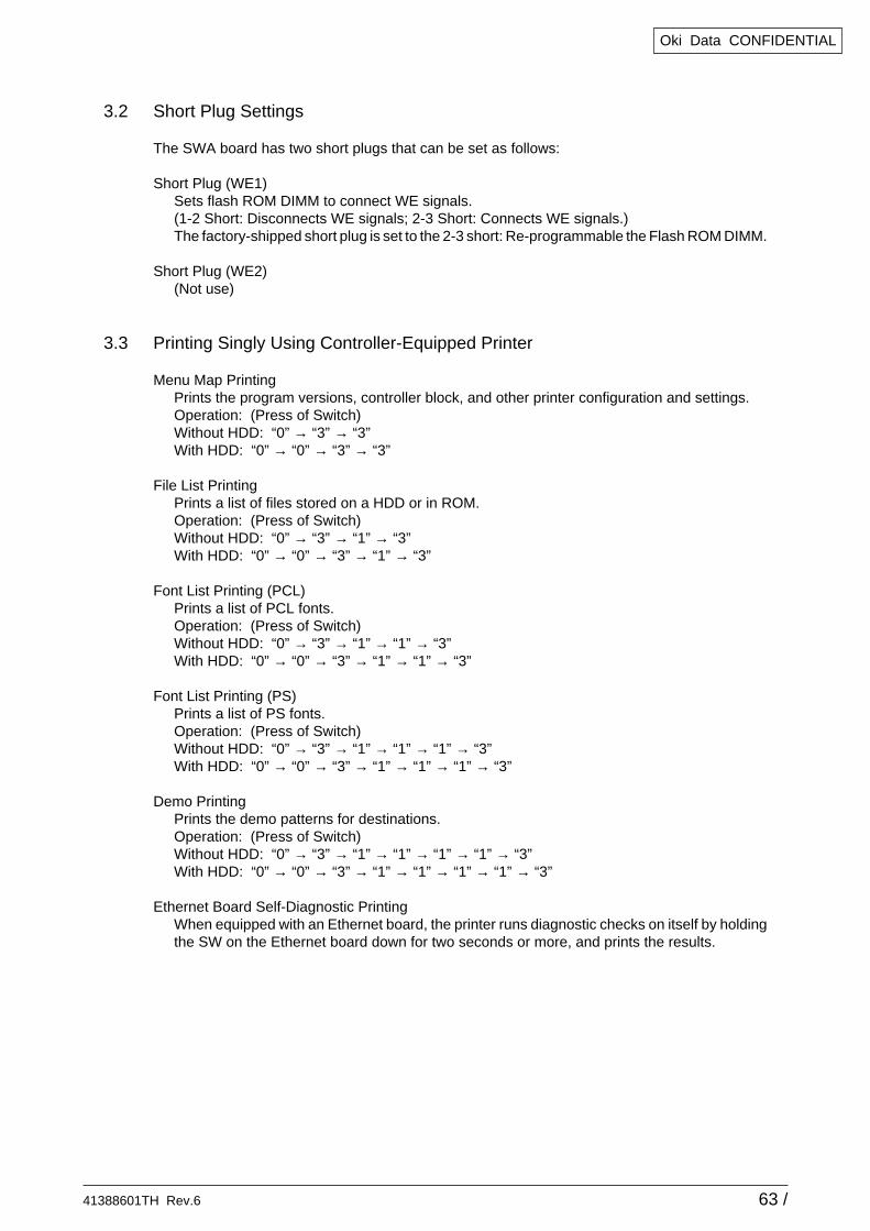
2.3.40 CU Assy
(1) Pulling out Control Board
1. Loosen the two screws 1.2. Pull the control board 2 out.3. Place the control board 2 on a flat table.
(2) Detaching Fan
1. Remove the connector 3.2. Remove the two screws 4.3. Detach the fan 5.
41388601TH Rev.6 61 /
Oki Data CONFIDENTIAL
8
C
0
D
9
0
H
B C
E
0
A
0
F
A
6
G
F
6
7
41848502(Board Assy.-cu[Maintenance])Attached screw.
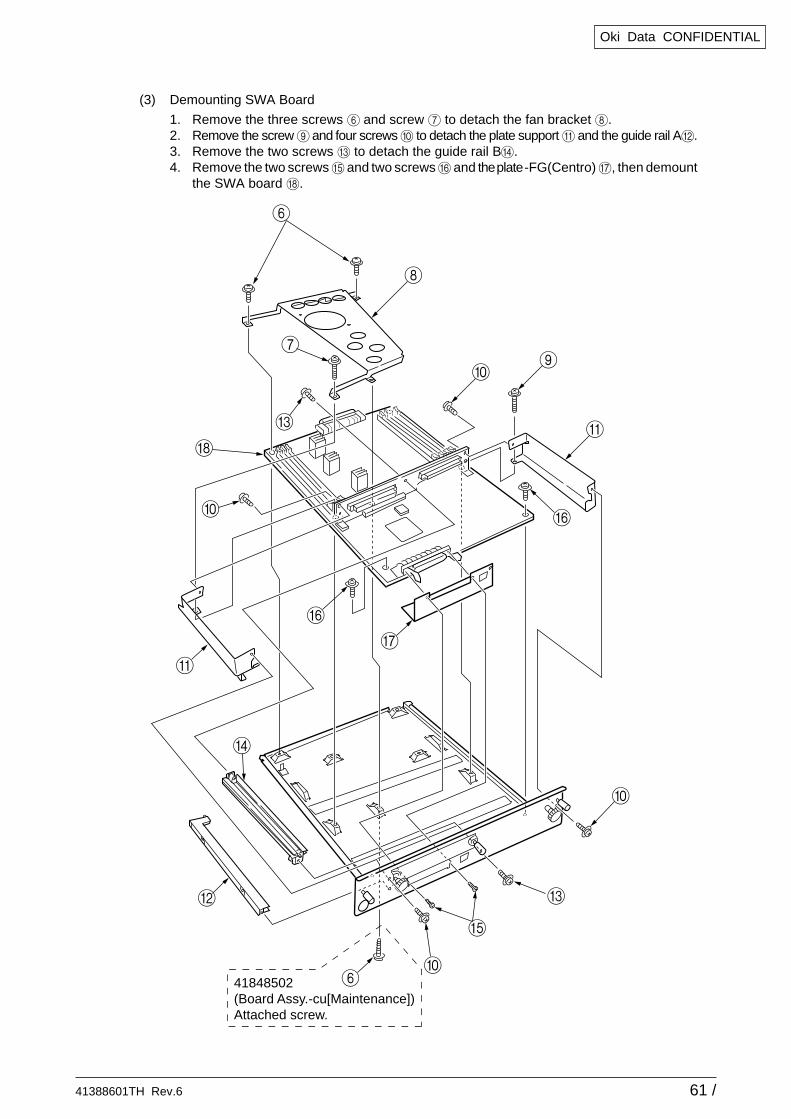
(3) Demounting SWA Board
1. Remove the three screws 6 and screw 7 to detach the fan bracket 8.2. Remove the screw 9 and four screws 0 to detach the plate support A and the guide rail AB.3. Remove the two screws C to detach the guide rail BD.4. Remove the two screws E and two screws F and the plate -FG(Centro) G, then demount
the SWA board H.
41388601TH Rev.6 62 /
Oki Data CONFIDENTIAL
3. ADJUSTMENT
Adjustments are carried out by key operations on the operator panel.
The maintenance menu is included in the general menu of this printer. Choose the maintenancemenu for adjustment.
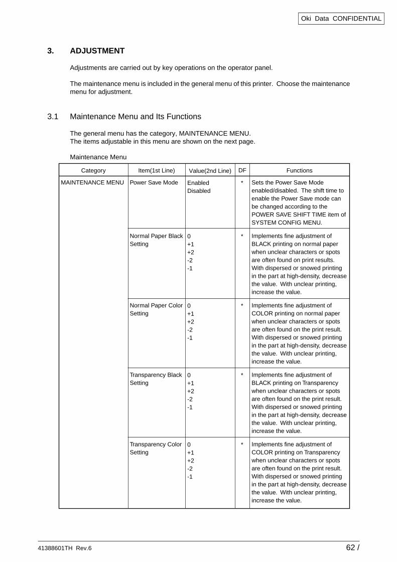
3.1 Maintenance Menu and Its Functions
The general menu has the category, MAINTENANCE MENU.The items adjustable in this menu are shown on the next page.
Maintenance Menu
Category
MAINTENANCE MENU
Item(1st Line)
Power Save Mode
Normal Paper Black Setting
Normal Paper Color Setting
Transparency Black Setting
Transparency Color Setting
Value(2nd Line)
EnabledDisabled
0+1+2-2-1
0+1+2-2-1
0+1+2-2-1
0+1+2-2-1
Functions
Sets the Power Save Mode enabled/disabled. The shift time to enable the Power Save mode can be changed according to the POWER SAVE SHIFT TIME item of SYSTEM CONFIG MENU.
Implements fine adjustment of BLACK printing on normal paper when unclear characters or spots are often found on print results. With dispersed or snowed printing in the part at high-density, decrease the value. With unclear printing, increase the value.
Implements fine adjustment of COLOR printing on normal paper when unclear characters or spots are often found on the print result. With dispersed or snowed printing in the part at high-density, decrease the value. With unclear printing, increase the value.
Implements fine adjustment of BLACK printing on Transparency when unclear characters or spots are often found on the print result. With dispersed or snowed printing in the part at high-density, decrease the value. With unclear printing, increase the value.
Implements fine adjustment of COLOR printing on Transparency when unclear characters or spots are often found on the print result. With dispersed or snowed printing in the part at high-density, decrease the value. With unclear printing, increase the value.
DF
*
*
*
*
*
41388601TH Rev.6 63 /
Oki Data CONFIDENTIAL
3.2 Short Plug Settings
The SWA board has two short plugs that can be set as follows:
Short Plug (WE1)Sets flash ROM DIMM to connect WE signals.(1-2 Short: Disconnects WE signals; 2-3 Short: Connects WE signals.)The factory-shipped short plug is set to the 2-3 short: Re-programmable the Flash ROM DIMM.
Short Plug (WE2)(Not use)
3.3 Printing Singly Using Controller-Equipped Printer
Menu Map PrintingPrints the program versions, controller block, and other printer configuration and settings.Operation: (Press of Switch)Without HDD: “0” → “3” → “3”With HDD: “0” → “0” → “3” → “3”
File List PrintingPrints a list of files stored on a HDD or in ROM.Operation: (Press of Switch)Without HDD: “0” → “3” → “1” → “3”With HDD: “0” → “0” → “3” → “1” → “3”
Font List Printing (PCL)Prints a list of PCL fonts.Operation: (Press of Switch)Without HDD: “0” → “3” → “1” → “1” → “3”With HDD: “0” → “0” → “3” → “1” → “1” → “3”
Font List Printing (PS)Prints a list of PS fonts.Operation: (Press of Switch)Without HDD: “0” → “3” → “1” → “1” → “1” → “3”With HDD: “0” → “0” → “3” → “1” → “1” → “1” → “3”
Demo PrintingPrints the demo patterns for destinations.Operation: (Press of Switch)Without HDD: “0” → “3” → “1” → “1” → “1” → “1” → “3”With HDD: “0” → “0” → “3” → “1” → “1” → “1” → “1” → “3”
Ethernet Board Self-Diagnostic PrintingWhen equipped with an Ethernet board, the printer runs diagnostic checks on itself by holdingthe SW on the Ethernet board down for two seconds or more, and prints the results.
41388601TH Rev.6 64 /
Oki Data CONFIDENTIAL
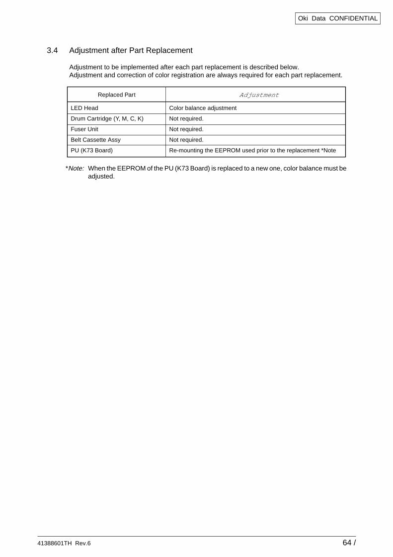
3.4 Adjustment after Part Replacement
Adjustment to be implemented after each part replacement is described below.Adjustment and correction of color registration are always required for each part replacement.
*Note: When the EEPROM of the PU (K73 Board) is replaced to a new one, color balance must beadjusted.
Replaced Part
LED Head
Drum Cartridge (Y, M, C, K)
Fuser Unit
Belt Cassette Assy
PU (K73 Board)
Adjustment
Color balance adjustment
Not required.
Not required.
Not required.
Re-mounting the EEPROM used prior to the replacement *Note
41388601TH Rev.6 65 /
Oki Data CONFIDENTIAL
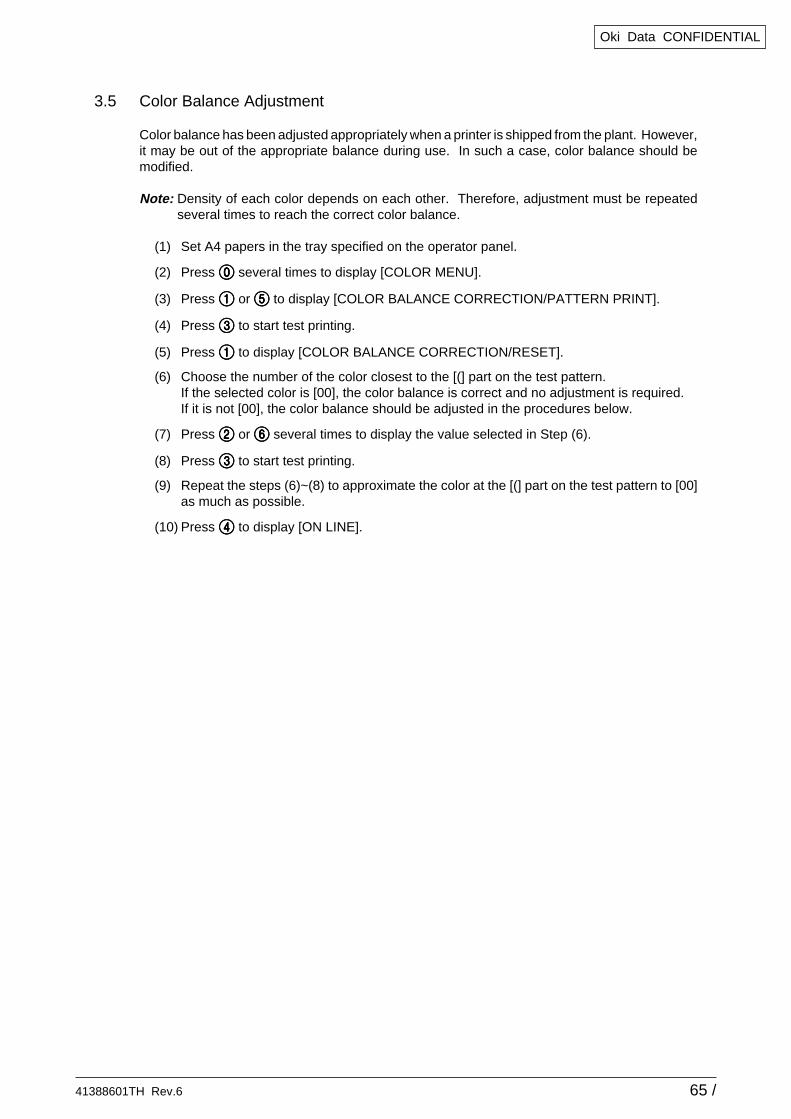
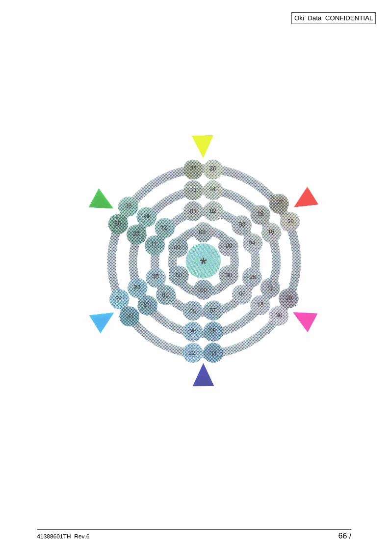
3.5 Color Balance Adjustment
Color balance has been adjusted appropriately when a printer is shipped from the plant. However,it may be out of the appropriate balance during use. In such a case, color balance should bemodified.
Note: Density of each color depends on each other. Therefore, adjustment must be repeatedseveral times to reach the correct color balance.
(1) Set A4 papers in the tray specified on the operator panel.
(2) Press ))))) several times to display [COLOR MENU].
(3) Press 11111 or 55555 to display [COLOR BALANCE CORRECTION/PATTERN PRINT].
(4) Press 33333 to start test printing.
(5) Press 11111 to display [COLOR BALANCE CORRECTION/RESET].
(6) Choose the number of the color closest to the [(] part on the test pattern.If the selected color is [00], the color balance is correct and no adjustment is required.If it is not [00], the color balance should be adjusted in the procedures below.
(7) Press 22222 or 66666 several times to display the value selected in Step (6).
(8) Press 33333 to start test printing.
(9) Repeat the steps (6)~(8) to approximate the color at the [(] part on the test pattern to [00]as much as possible.
(10) Press 44444 to display [ON LINE].
41388601TH Rev.6 66 /
Oki Data CONFIDENTIAL
41388601TH Rev.6 67 /
Oki Data CONFIDENTIAL
3.6 EEPROM Replacement after SWA Board and K73 Board Replacement
When replacing the SWA Board or K73 Board, the EEPROM used by the user must be removedand re-mounted on the new board (to deliver the user setting and font installment information tothe new board).If the EEPROM used by the user is broken and not suitable for further use, the EEPROM on thenew board may be used.
41388601TH Rev.6 68 /
Oki Data CONFIDENTIAL
4. REGULAR MAINTENANCE
4.1 Parts to be Replaced Regularly
It is recommended that a user should replace the parts below regularly according to thereplacement standard. (If not replaced, print quality is not assumed or it may result in a failure.)
Part Name
Large-capacity Toner Cartridge
Toner Cartridge
ID Cartridge
Fuser Unit
Belt Unit
Time for Replacement
When the message “Toner Low” is displayed.
When the message “Drum Life” is displayed.
When the message “Fuser Life” is displayed.
When the message “Belt Life” is displayed.
Replacement Condition
After 15,000 copies have been printed.
After 7,500 copies have been printed.
After 26,000 copies have been printed. (at 3P/J)
After 80,000 copies have been printed.
After 80,000 copies have been printed. (at 3P/J)
Adjustment after Replacement
Replace the Toner cartridge.
Reset the drum counter after drum replacement.
Reset the fuser counter.
Reset the belt counter.
The above regular part replacement is performed by a user.
4.2 Cleaning
The inside and outside of this printer should be cleaned with wastes and hand cleaner, if necessary.
Note: Do not touch the Image drum terminal, LED lens array and LED head connectors.
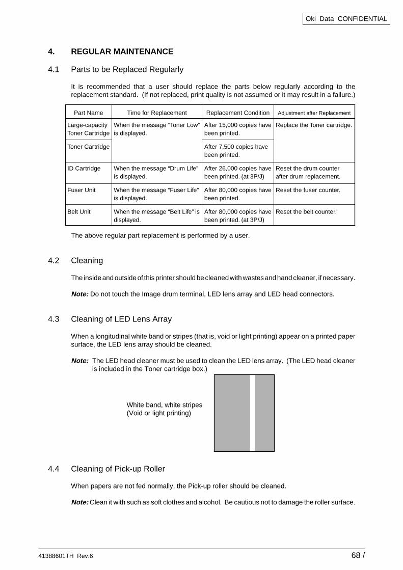
4.3 Cleaning of LED Lens Array
When a longitudinal white band or stripes (that is, void or light printing) appear on a printed papersurface, the LED lens array should be cleaned.
Note: The LED head cleaner must be used to clean the LED lens array. (The LED head cleaneris included in the Toner cartridge box.)
4.4 Cleaning of Pick-up Roller
When papers are not fed normally, the Pick-up roller should be cleaned.
Note: Clean it with such as soft clothes and alcohol. Be cautious not to damage the roller surface.
White band, white stripes(Void or light printing)
41388601TH Rev.6 69 /
Oki Data CONFIDENTIAL
5. TROUBLESHOOTING PROCEDURES
5.1 Tips for Troubleshooting
(1) Check the basic check points covered in the user’s manual.
(2) Gather as much information on the problem from the customer as possible.
(3) Perform inspections in conditions close to those in which the problem had occurred.
5.2 Check Points before Correcting Image Problems
(1) Is the printer being run in proper ambient conditions?
(2) Have the consumables toner and image drum cartridges been replaced properly?
(3) Is the paper normal? See paper specifications section.
(4) Has the image drum cartridge been loaded properly?
5.3 Tips for Correcting Image Problems
(1) Do not touch, or bring foreign matter into contact with the image drum surface.
(2) Do not expose the image drum to direct sunlight.
(3) Keep hands off the fuser unit as it is heated during operation.
(4) Do not expose the image drum to light for longer than 5 minutes at room temperature.
41388601TH Rev.6 70 /
Oki Data CONFIDENTIAL
5.4 Preparation for Troubleshooting
(1) Operator panel display
The failure status of this printer is indicated on the LCD (liquid crystal display) of the Operatorpanel.Take the proper corrective action according to the message displayed on the LCD.
5.5 Troubleshooting Flow
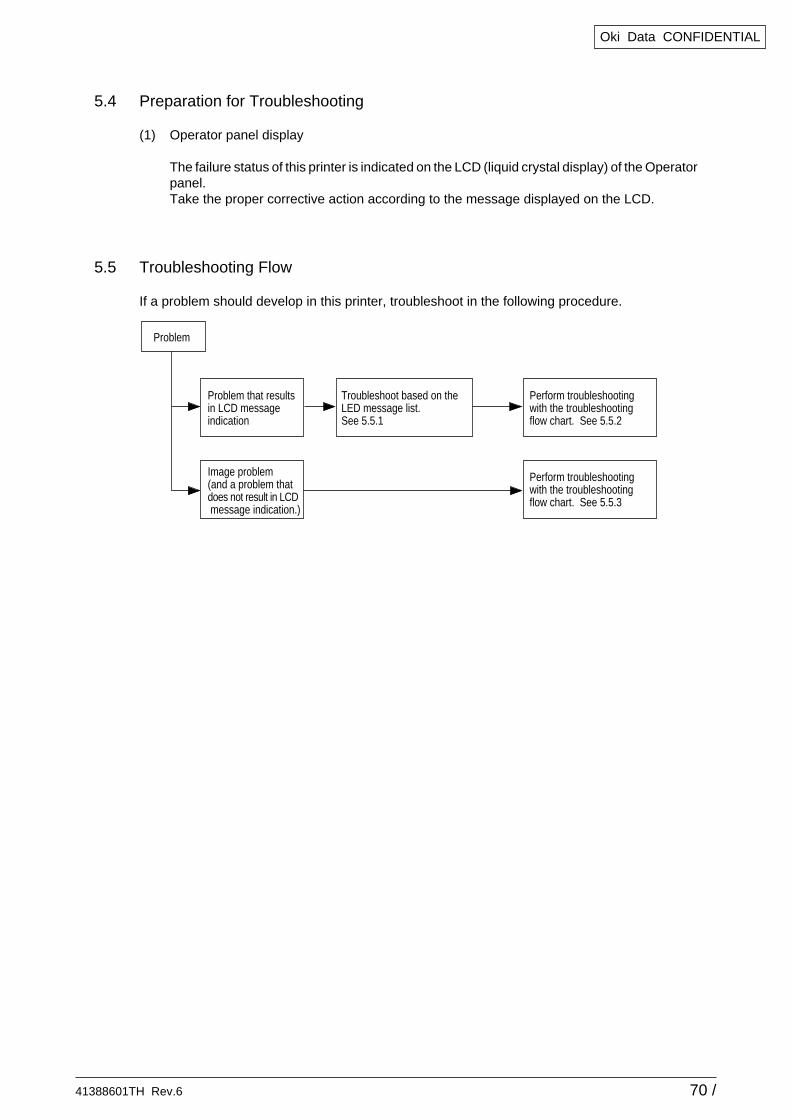
If a problem should develop in this printer, troubleshoot in the following procedure.
Problem
Problem that resultsin LCD message indication
Image problem(and a problem that does not result in LCD message indication.)
Perform troubleshooting with the troubleshooting flow chart. See 5.5.2
Perform troubleshootingwith the troubleshootingflow chart. See 5.5.3
Troubleshoot based on the LED message list.See 5.5.1
41388601TH Rev.6 71 /
Oki Data CONFIDENTIAL
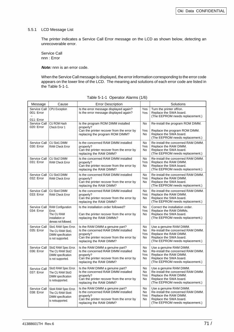
5.5.1 LCD Message List
The printer indicates a Service Call Error message on the LCD as shown below, detecting anunrecoverable error.
Service Callnnn : Error
Note: nnn is an error code.
When the Service Call message is displayed, the error information corresponding to the error codeappears on the lower line of the LCD. The meaning and solutions of each error code are listed inthe Table 5-1-1.
Table 5-1-1 Operator Alarms (1/6)
Message Cause Error Description SolutionsService Call001: Error ~011: Error
CPU Exception Is the error message displayed again?Is the error message displayed again?
YesYes
Turn the printer off/on.Replace the SWA board.(The EEPROM needs replacement.)
Service Call020: Error
CU ROM HashCheck Error 1
Is the program ROM DIMM installed properly?Can the printer recover from the error by replacing the program ROM DIMM?
No
YesNo
Re-install the program ROM DIMM.
Replace the program ROM DIMM.Replace the SWA board.(The EEPROM needs replacement.)
Service Call030: Error
CU Slot1 DIMMRAM Check Error
Is the concerned RAM DIMM installed properly?Can the printer recover from the error byreplacing the RAM DIMM?
NoYesNo
Re-install the concerned RAM DIMM.Replace the RAM DIMM.Replace the SWA board.(The EEPROM needs replacement.)
Service Call031: Error
CU Slot2 DIMMRAM Check Error
Is the concerned RAM DIMM installed properly?Can the printer recover from the error byreplacing the RAM DIMM?
NoYesNo
Re-install the concerned RAM DIMM.Replace the RAM DIMM.Replace the SWA board.(The EEPROM needs replacement.)
Service Call032: Error
CU Slot3 DIMMRAM Check Error
Is the concerned RAM DIMM installed properly?Can the printer recover from the error byreplacing the RAM DIMM?
NoYesNo
Re-install the concerned RAM DIMM.Replace the RAM DIMM.Replace the SWA board.(The EEPROM needs replacement.)
Service Call033: Error
CU Slot4 DIMMRAM Check Error
Is the concerned RAM DIMM installed properly?Can the printer recover from the error byreplacing the RAM DIMM?
NoYesNo
Re-install the concerned RAM DIMM.Replace the RAM DIMM.Replace the SWA board.(The EEPROM needs replacement.)
Service Call034: Error
RAM ConfigurationError.The CU RAM installation or derwas not followed.
Is the installation order followed?
Can the printer recover from the error byreplacing the RAM DIMMs?
NoYesNo
Correct the installation order.Replace the RAM DIMMs.Replace the SWA board.(The EEPROM needs replacement.)
Service Call035: Error
Slot1 RAM Spec Error.The CU RAM Slot1DIMM specification is not supported.
Is the RAM DIMM a genuine part?Is the concerned RAM DIMM installedproperly?Can the printer recover from the error byreplacing the RAM DIMM?
NoNoYesNo
Use a genuine RAM DIMM.Re-install the concerned RAM DIMM.Replace the RAM DIMM.Replace the SWA board.(The EEPROM needs replacement.)
Service Call036: Error
Service Call037: Error
Service Call038: Error
Slot2 RAM Spec Error.
Slot3 RAM Spec Error.
Slot4 RAM Spec Error.
The CU RAM Slot2DIMM specification is not supported.
Is the RAM DIMM a genuine part?Is the concerned RAM DIMM installedproperly?Can the printer recover from the error byreplacing the RAM DIMM?
NoNoYesNo
Use a genuine RAM DIMM.Re-install the concerned RAM DIMM.Replace the RAM DIMM.Replace the SWA board.(The EEPROM needs replacement.)
Is the RAM DIMM a genuine part?Is the concerned RAM DIMM installedproperly?Can the printer recover from the error byreplacing the RAM DIMM?
NoNoYesNo
Use a genuine RAM DIMM.Re-install the concerned RAM DIMM.Replace the RAM DIMM.Replace the SWA board.(The EEPROM needs replacement.)
Is the RAM DIMM a genuine part?Is the concerned RAM DIMM installedproperly?Can the printer recover from the error byreplacing the RAM DIMM?
NoNoYesNo
Use a genuine RAM DIMM.Re-install the concerned RAM DIMM.Replace the RAM DIMM.Replace the SWA board.(The EEPROM needs replacement.)
The CU RAM Slot3DIMM specification is notsupported.
The CU RAM Slot4DIMM specification is notsupported.
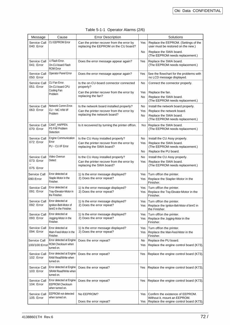
41388601TH Rev.6 72 /
Oki Data CONFIDENTIAL
Service Call040: Error
CU EEPROM Error Can the printer recover from the error byreplacing the EEPROM on the CU board?
Yes
No
Replace the EEPROM. (Settings of theuser must be restored on the new.)
Replace the SWA board.(The EEPROM needs replacement.)
Service Call041: Error
U Flash Error.On-CU-board Flash ROM Error
Does the error message appear again? Yes Replace the SWA board.(The EEPROM needs replacement.)
Service Call050: Error
Operator Panel Error Does the error message appear again? Yes See the flowchart for the problems withno LCD message displayed.
Service Call051: Error
CU Fan Error.On-CU-board CPUCooling Fan Problem
Is the on-CU-board connector connected properly?
Can the printer recover from the error byreplacing the fan?
No
Yes
No
Connect the connector properly.
Replace the fan.
Replace the SWA board.(The EEPROM needs replacement.)
Service Call063: Error
Network Comm.Error.CU ~ NIC H/W I/FProblem
Is the network board installed properly?
Can the printer recover from the error byreplacing the network board?
No
Yes
No
Install the network board properly.
Replace the network board.
Replace the SWA board.(The EEPROM needs replacement.)
Service Call070: Error
CANT_HAPPEN.PS F/W Problem Detection
Is it recovered by turning the printer off/on. No Replace the SWA board.(The EEPROM needs replacement.)
Service Call072: Error
Engine Communication Error
PU ~ CU I/F Error
Is the CU Assy installed properly?
Can the printer recover from the error byreplacing the SWA board?
No
Yes
No
Install the CU Assy properly.
Replace the SWA board.(The EEPROM needs replacement.)
Replace the PU board.
Service Call073: Error~075: Error
Video OverrunDetect
Is the CU Assy installed properly?
Can the printer recover from the error byreplacing the SWA board?
No
Yes
Install the CU Assy properly.
Replace the SWA board.(The EEPROM needs replacement.)
Service Call
090:Error
Error detected atStaple-Motor in the Finisher.
1) Is the error message displayed? Yes
Yes
Turn off/on the printer.
Replace the Stapler-Motor in theFinisher.
Yes Replace the Tray-Elevator-Motor in theFinisher.
Service Call091: Error
Error detected atTray-Elevator-Motor in the Finisher.
1) Is the error message displayed? Yes Turn off/on the printer.
Yes Replace the Ignition-Belt-Motor of bin#2 inthe Finisher.
Yes Turn off/on the printer.
Yes Replace the Jogging-Motor in theFinisher.
Yes Turn off/on the printer.
Yes Replace the Main-Feed-Motor in theFinisher.
Yes Turn off/on the printer.
Service Call092: Error
Error detected atIgnition-Belt-Motor of bin#2 in the Finisher.
1) Is the error message displayed?
Service Call093: Error
Error detected atJogging-Motor in theFinisher.
Error detected atMain-Feed-Motor in theFinisher.
Service Call094: Error
2) Does the error repeat?
2) Does the error repeat?
2) Does the error repeat?
1) Is the error message displayed?2) Does the error repeat?
1) Is the error message displayed?2) Does the error repeat?
Service Call
100/100:Error
Error detected at EngineROM Checksum when turned on.
Does the error repeat? No
Yes
Replace the PU board.
Replace the engine control board (K73).
Service Call102: Error
Error detected at EngineRAM Read/Write when turned on.
Does the error repeat? Yes Replace the engine control board (K73).
Service Call103: Error
Error detected at EngineSRAM Read/Write when turned on.
Does the error repeat? Yes Replace the engine control board (K73).
Service Call104: Error
Error detected at EngineEEPROM Checksumwhen turned on.
Does the error repeat? Yes Replace the engine control board (K73).
Service Call105: Error
EEPROM not detected when turned on.
No EEPROM?
Does the error repeat?
Yes
Yes
Confirm the existence of EEPROM.Without it, mount an EEPROM.Replace the engine control board (K73).
Message Cause Error Description Solutions
Table 5-1-1 Operator Alarms (2/6)
41388601TH Rev.6 73 /
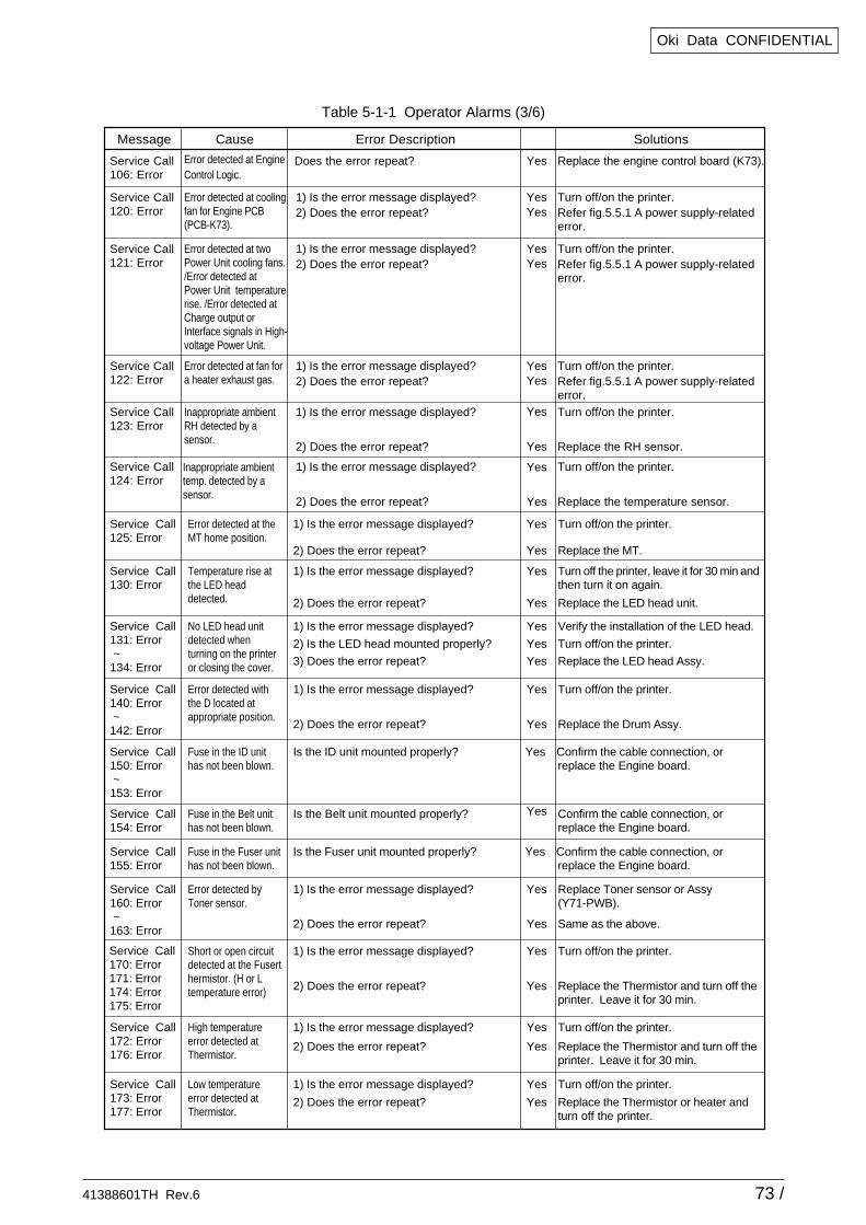
Oki Data CONFIDENTIAL
Table 5-1-1 Operator Alarms (3/6)
Service Call125: Error
Error detected at theMT home position.
1) Is the error message displayed?
2) Does the error repeat?
Yes
Yes
Turn off/on the printer.
Replace the MT.
Service Call130: Error
Temperature rise atthe LED headdetected.
1) Is the error message displayed?
2) Does the error repeat?
Yes
Yes
Turn off the printer, leave it for 30 min andthen turn it on again.
Replace the LED head unit.
Service Call131: Error ~134: Error
No LED head unitdetected whenturning on the printeror closing the cover.
1) Is the error message displayed?
2) Is the LED head mounted properly?
3) Does the error repeat?
Yes
Yes
Yes
Verify the installation of the LED head.
Turn off/on the printer.
Replace the LED head Assy.
Service Call140: Error ~142: Error
Error detected withthe D located atappropriate position.
1) Is the error message displayed?
2) Does the error repeat?
Yes
Yes
Turn off/on the printer.
Replace the Drum Assy.
Service Call150: Error ~153: Error
Fuse in the ID unithas not been blown.
Is the ID unit mounted properly? Yes Confirm the cable connection, orreplace the Engine board.
Service Call154: Error
Fuse in the Belt unithas not been blown.
Is the Belt unit mounted properly? Yes Confirm the cable connection, orreplace the Engine board.
Service Call155: Error
Fuse in the Fuser unit has not been blown.
Is the Fuser unit mounted properly? Yes Confirm the cable connection, orreplace the Engine board.
Service Call160: Error ~163: Error
Error detected byToner sensor.
1) Is the error message displayed?
2) Does the error repeat?
Yes
Yes
Replace Toner sensor or Assy(Y71-PWB).
Same as the above.
Service Call170: Error171: Error174: Error175: Error
Short or open circuitdetected at the Fuserthermistor. (H or Ltemperature error)
1) Is the error message displayed?
2) Does the error repeat?
Yes
Yes
Turn off/on the printer.
Replace the Thermistor and turn off theprinter. Leave it for 30 min.
Service Call172: Error176: Error
High temperatureerror detected atThermistor.
1) Is the error message displayed?
2) Does the error repeat?
Yes
Yes
Turn off/on the printer.
Replace the Thermistor and turn off theprinter. Leave it for 30 min.
Service Call173: Error177: Error
Low temperatureerror detected atThermistor.
1) Is the error message displayed?
2) Does the error repeat?
Yes
Yes
Turn off/on the printer.
Replace the Thermistor or heater andturn off the printer.
Service Call120: Error
Service Call106: Error
Error detected at EngineControl Logic.
Does the error repeat? Yes
YesYes
Yes
Yes
Yes
Yes
Replace the engine control board (K73).
Error detected at coolingfan for Engine PCB(PCB-K73).
1) Is the error message displayed?2) Does the error repeat?
Turn off/on the printer.Refer fig.5.5.1 A power supply-relatederror.
Service Call122: Error
YesYes
Error detected at fan fora heater exhaust gas.
1) Is the error message displayed?2) Does the error repeat?
Turn off/on the printer.Refer fig.5.5.1 A power supply-relatederror.
Service Call121: Error
YesYes
Error detected at twoPower Unit cooling fans./Error detected at Power Unit temperaturerise. /Error detected at Charge output orInterface signals in High-voltage Power Unit.
1) Is the error message displayed?2) Does the error repeat?
Turn off/on the printer.Refer fig.5.5.1 A power supply-relatederror.
Service Call123: Error
Inappropriate ambient RH detected by a sensor.
1) Is the error message displayed?
2) Does the error repeat?
Turn off/on the printer.
Replace the RH sensor.
Service Call124: Error
Inappropriate ambienttemp. detected by asensor.
1) Is the error message displayed?
2) Does the error repeat?
Turn off/on the printer.
Replace the temperature sensor.
Message Cause Error Description Solutions
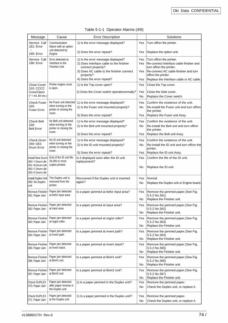
41388601TH Rev.6 74 /
Oki Data CONFIDENTIAL
Table 5-1-1 Operator Alarms (4/6)
Install New Drum350: Y Drum Life351: M Drum Life352: C Drum Life353: K Drum Life
End of the ID unit life.26,000 or morecopies printed.
Is it displayed soon after the ID unit replacement?
Yes
No
Confirm the life of the ID unit.
Replace the ID unit.
Install Duplex Unit360: No Duplexunit
The Duplex unit isremoved from theprinter.
Recovered if the Duplex unit is inserted again?
Yes
No
Normal
Replace the Duplex unit or Engine board.
Check DUPLEX370: Paper Jam
Paper jam detectedafter paper reverse inthe Duplex unit.
1) Is a paper jammed in the Duplex unit? Yes
No
Remove the jammed paper.
Check the Duplex unit, or replace it.
Remove Finisher361: Paper Jam
Paper jam detectedat befor input area.
Is a paper jammed at befor input area? Yes
No
Remove the jammed paper.(See Fig.5.5.2 No.361)Replace the Finisher unit.
Remove Finisher362: Paper Jam
Paper jam detectedat input area.
Is a paper jammed at input area? Yes
No
Remove the jammed paper.(See Fig.5.5.2 No.362)Replace the Finisher unit.
Remove Finisher363: Paper Jam
Paper jam detectedat regist roller.
Is a paper jammed at regist roller? Yes
No
Remove the jammed paper.(See Fig.5.5.2 No.363)Replace the Finisher unit.
Remove Finisher364: Paper Jam
Paper jam detectedat invert path.
Is a paper jammed at invert path? Yes
No
Remove the jammed paper.(See Fig.5.5.2 No.364)Replace the Finisher unit.
Remove Finisher365: Paper Jam
Paper jam detectedat invert stack.
Is a paper jammed at invert stack? Yes
No
Remove the jammed paper.(See Fig.5.5.2 No.365)Replace the Finisher unit.
Remove Finisher366: Paper Jam
Paper jam detectedat Bin#1 exit.
Is a paper jammed at Bin#1 exit? Yes
No
Remove the jammed paper.(See Fig.5.5.2 No.366)Replace the Finisher unit.
Remove Finisher367: Paper Jam
Paper jam detectedat Bin#2 exit.
Is a paper jammed at Bin#2 exit? Yes
No
Remove the jammed paper.(See Fig.5.5.2 No.367)Replace the Finisher unit.
Check DUPLEX371: Paper Jam
Paper jam detectedat the Duplex unit
1) Is a paper jammed in the Duplex unit? Yes
No
Remove the jammed paper.
Check the Duplex unit, or replace it.
Service Call181: Error ~185: Error
Communicationfailure with an optionunit detected byEngine
1) Is the error message displayed?
2) Does the error repeat?
Yes
Yes
Turn off/on the printer.
Replace the option unit.
Service Call186: Error
Error detected atInterface to theFinisher-Unit.
1) Is the error message displayed?
3) Does AC cable to the finisher connect properly?
Yes
Yes
Turn off/on the printer.
Replace the Interface cable or AC cable.
2) Does Interface cable to the finisher connect properly?
4) Does the error repeat?
Yes Re-connect Interface cable finisher andturn off/on the printer.
Yes Re-connect AC cable finisher and turnoff/on the printer.
Yes
Yes
No
Yes
No
Yes
Yes
No
Yes
Yes
No
Yes
Close Cover310: CCCC CoverOpen(* = A4, B4 etc.)
Printer engine coveris open.
1) Is the Top cover open?
2) Does the Cover switch operatenormally?
Close the Top cover.
Close the Side cover.
Replace the Cover switch.
Check Fuser320: Fuser Error
No Fuser unit detected when turning on the printer or closing the cover.
1) Is the error message displayed?
2) Is the Fuser unit mounted properly?
3) Does the error repeat?
Confirm the existence of the unit.
Re-install the Fuser unit and turn off/onthe printer.Replace the Fuser unit Assy.
Check Belt330: Belt Error
No Belt unit detectedwhen turning on theprinter or closing thecover.
1) Is the error message displayed?
2) Is the Belt unit mounted properly?
3) Does the error repeat?
Confirm the existence of the unit.
Re-install the Belt unit and turn off/onthe printer.Replace the Belt unit Assy.
Check Drum340~343:Drum Error
No ID unit detectedwhen turning on theprinter or closing thecover.
1) Is the error message displayed?
2) Is the ID unit mounted properly?
3) Does the error repeat?
Confirm the existence of the unit.
Re-install the ID unit and turn off/on theprinter.Replace the ID unit Assy.
Message Cause Error Description Solutions
41388601TH Rev.6 75 /
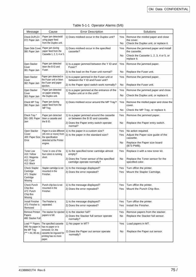
Oki Data CONFIDENTIAL
Table 5-1-1 Operator Alarms (5/6)
Check DUPLEX372: Paper Jam
Paper jam detectedduring paper feedfrom the Duplex unit.
1) Does misfeed occur in the Duplex unit? Yes
No
Remove the misfed paper and close the cover.Check the Duplex unit, or replace it.
Open Side Cover380: Paper Jam
Paper jam duringpaper feed from theCassette 1, 2, 3, 4 or 5.
1) Does misfeed occur in the specified cassette?
Yes
No
Remove the jammed paper and install the cassette.
Check the Cassette 1, 2, 3, 4 or 5, orreplace it.
Open StackerCover381: Paper Jam
Paper jam detectedbtwn the B ID andFuser.
1) Is a paper jammed between the Y ID and Fuser?
2) Is the load on the Fuser unit normal?
Yes
No
Remove the jammed paper.
Replace the Fuser unit.
Open StackerCover382: Paper Jam
Paper jam detected inthe Fuser unit or btwnthe Fuser and paperejection.
1) Is a paper jammed in the Fuser unit or between the Y ID and Fuser unit?
2) Is the Paper eject switch work normally?
Yes
No
Remove the jammed paper.
Replace the Fuser unit.
Open StackerCover383: Paper Jam
Paper jam detectedon paper enteringthe Duplex unit.
1) Is a paper jammed at the entrance of the Duplex unit or in the unit?
Yes
No
Remove the jammed paper and close.
Check the Duplex unit, or replace it.
Check MP Tray390: Paper Jam
Paper jam duringpaper feed from theMP Tray.
1) Does misfeed occur around the MP Tray? Yes
No
Remove the misfed paper and close thecover.
Check the MP Tray, or replace it.
Check Tray *391~395: PaperJam
Paper jam detected btwn a cassette and the B ID.
1) Is a paper jammed around the cassette or between the B ID and cassette.
2) Does the Paper entry switch operate normal?
Yes
No
Remove the jammed paper.
Replace the Paper entry switch.
Open StackerCover400: Paper SizeError
Paper in a size different (45 mm or more) from the specification detected at the Printer engine.
1) Is the paper in a custom size?
2) Is the paper in the standard size?
Yes
Yes
No
No action required.
Adjust the Paper size guide of the cassette.
Check StaplerCartridge471: StaplerCartridgeMissing
Stapler cartridge is notmounted in theFinisher.
1) Is the message displayed?
2) Does the error repeated?
Yes
Yes
Turn off/on the printer.
Mount the Stapler Cartridge.
Check PunchChip Box472: PunchChip BoxMissing
Punch chip box is notmounted in theFinisher.
1) Is the message displayed?
2) Does the error repeated?
Yes
Yes
Turn off/on the printer.
Mount the Punch Chip Box.
Install Finisher473: Finisher isRemoved
The Finisher isseparated.
1) Is the message displayed?
2) Does the error repeated?
Yes
Yes
Turn off/on the printer.
Install the Finisher.
Replace the Paper size board (B73 PWB).
Toner Low410: Yellow411: Magenta412: Cyan413: Black
Toner in one of the four colors is running short.
1) Is the specified toner cartridge almost empty?
2) Does the Toner sensor of the specified cartridge operate normally?
Yes
No
Replace it with a new toner kit.
Replace the Toner sensor for the specified color.
Remove PrintedPapers480: Stacker Full
The stacker for ejected papers is full.
1) Is the stacker full?
2) Does the Stacker full sensor operate normally?
Yes
No
Remove papers from the stacker.
Replace the Stacker full sensor.
Load *** Papers490: No paper inthe MP Tray(*** = A4, B5 etc.)
The specified cassette has no paper or isremoved. Or, thecassette be ingused for printing has no morepaper.
1) No paper in MT?
2) Does the Paper out sensor operate normally?
Yes
No
Load papers in MT.
Replace the Paper out sensor.
Message Cause Error Description Solutions
41388601TH Rev.6 76 /
Oki Data CONFIDENTIAL
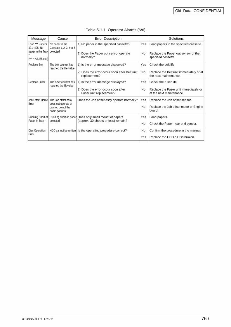
Table 5-1-1 Operator Alarms (6/6)
Load *** Papers491~495: Nopaper in the Tray*(*** = A4, B5 etc.)
No paper in theCassette 1, 2, 3, 4 or 5 detected.
1) No paper in the specified cassette?
2) Does the Paper out sensor operate normally?
Yes
No
Load papers in the specified cassette.
Replace the Paper out sensor of the specified cassette.
Replace Belt The belt counter has reached the life value.
1) Is the error message displayed?
2) Does the error occur soon after Belt unit replacement?
Yes
No
Check the belt life.
Replace the Belt unit immediately or at the next maintenance.
Replace Fuser The fuser counter has reached the lifevalue
1) Is the error message displayed?
2) Does the error occur soon after Fuser unit replacement?
Yes
No
Check the fuser life.
Replace the Fuser unit immediately or at the next maintenance.
Job Offset HomeError
The Job offset assy does not operate or cannot detect the home position.
Does the Job offset assy operate normally? Yes
No
Replace the Job offset sensor.
Replace the Job offset motor or Engineboard.
Running Short ofPaper in Tray *
Running short of paper detected
Does only small mount of papers(approx. 30 sheets or less) remain?
Yes
No
Load papers.
Check the Paper near end sensor.
Disc OperationError
HDD cannot be written. Is the operating procedure correct? No
Yes
Confirm the procedure in the manual.
Replace the HDD as it is broken.
Message Cause Error Description Solutions
41388601TH Rev.6 77 /
Oki Data CONFIDENTIAL
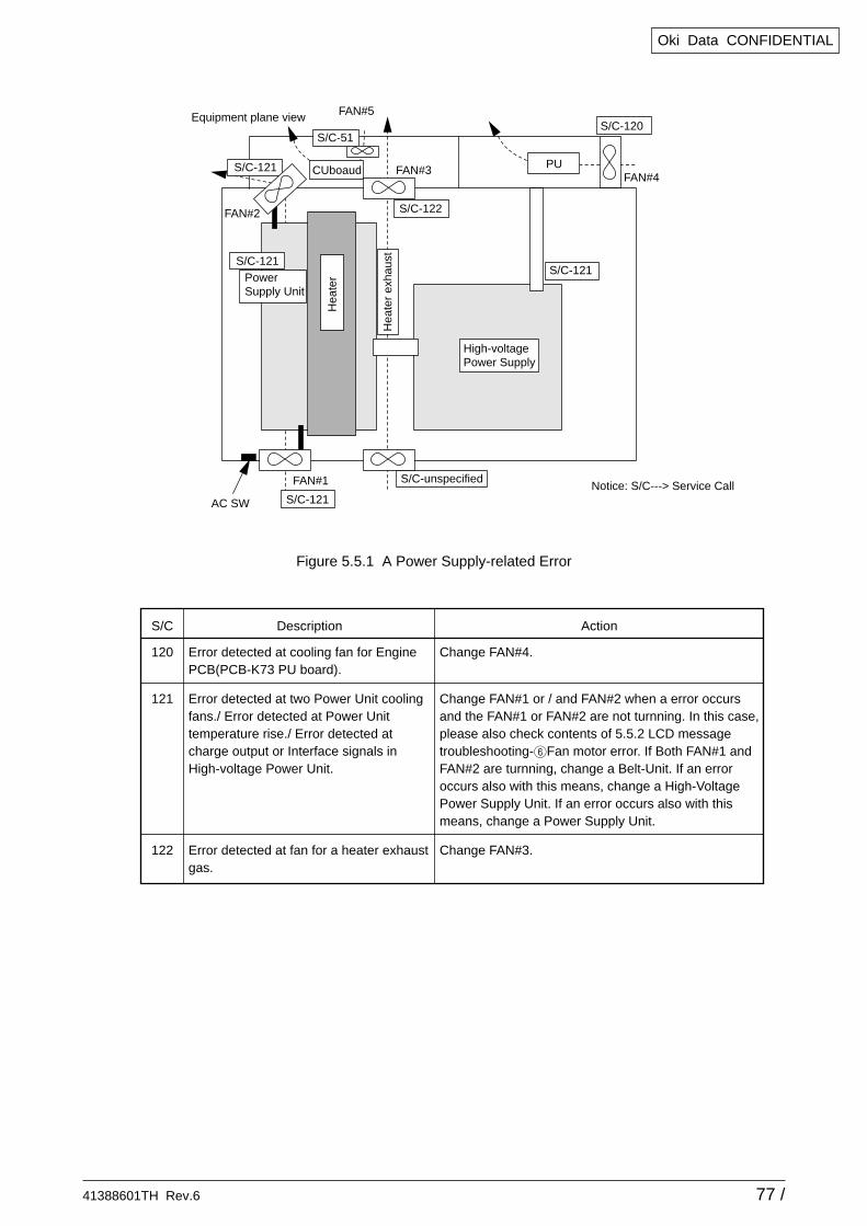
S/C-121AC SW
S/C-unspecified
S/C-121
S/C-120S/C-51
FAN#5
FAN#1
FAN#2
FAN#3FAN#4
Equipment plane view
Notice: S/C---> Service Call
S/C-121
Hea
ter
exha
ust
PowerSupply Unit
High-voltagePower Supply
S/C-121
S/C-122
CUboaud PU
Hea
ter
S/C
120
121
122
Description
Error detected at cooling fan for Engine PCB(PCB-K73 PU board).
Error detected at two Power Unit cooling fans./ Error detected at Power Unit temperature rise./ Error detected at charge output or Interface signals in High-voltage Power Unit.
Error detected at fan for a heater exhaust gas.
Action
Change FAN#4.
Change FAN#1 or / and FAN#2 when a error occurs and the FAN#1 or FAN#2 are not turnning. In this case, please also check contents of 5.5.2 LCD message troubleshooting-6Fan motor error. If Both FAN#1 and FAN#2 are turnning, change a Belt-Unit. If an error occurs also with this means, change a High-Voltage Power Supply Unit. If an error occurs also with this means, change a Power Supply Unit.
Change FAN#3.
Figure 5.5.1 A Power Supply-related Error
41388601TH Rev.6 78 /
Oki Data CONFIDENTIAL
JAM 06 JAM 03Punch
Punchunit
Invertpath
Staplepath
Accumulator
Paper Feed Knob
JAM 02JAM 01
JAM 05
JAM 07
JAM 04
A
KQ
a
h
e
f
g
b
c
dB
M
N
Sensor
Switch
Roller
Motor
Paper path
O
P
C
DL
F
G
J
E
RH
I
Upper cover (no sensor)
Lower cover
Bin 1 (face up)
Bin 2 (face down)
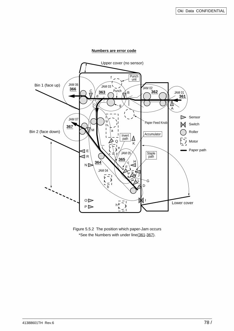
Numbers are error code
361
365364
367
366363 362
Figure 5.5.2 The position which paper-Jam occurs
*See the Numbers with under line(361-367).
41388601TH Rev.6 79 /
Oki Data CONFIDENTIAL
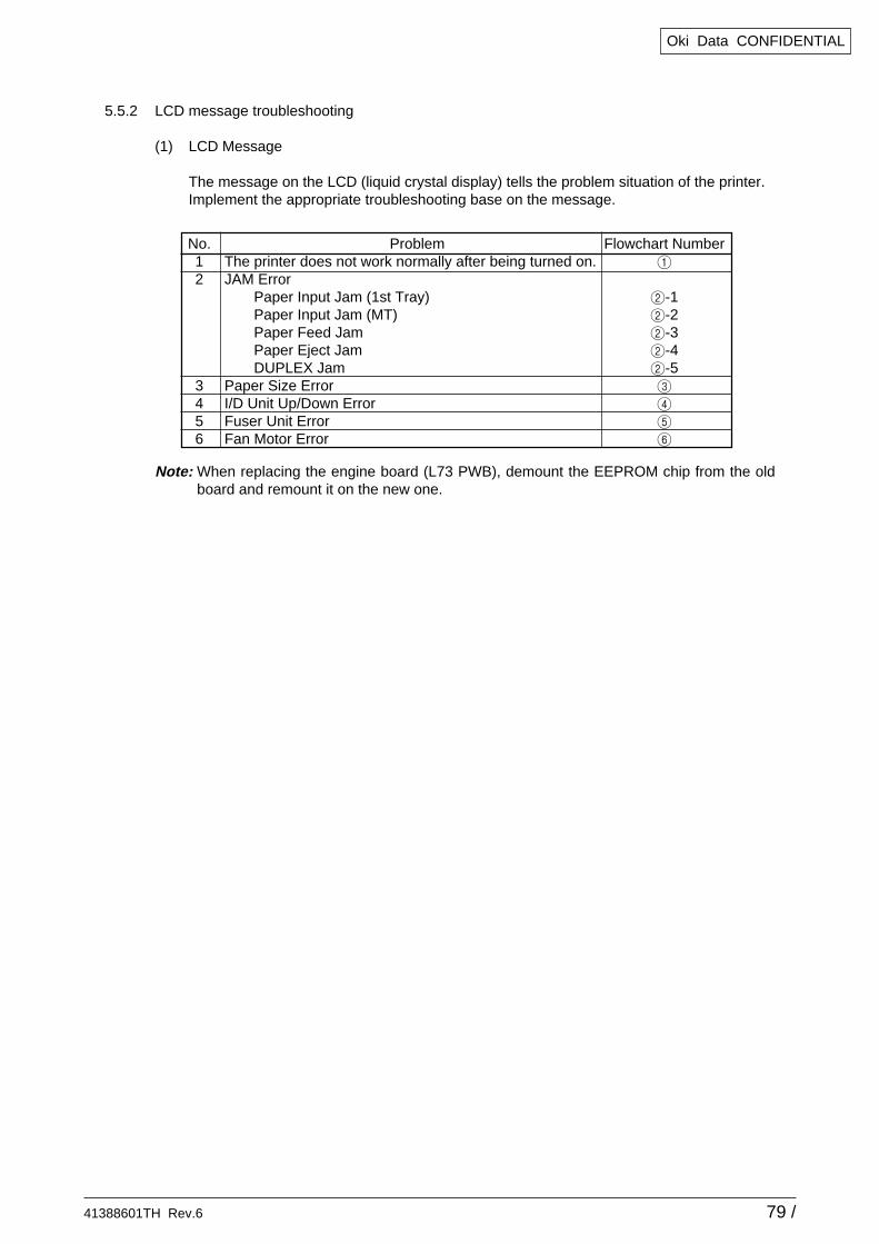
5.5.2 LCD message troubleshooting
(1) LCD Message
The message on the LCD (liquid crystal display) tells the problem situation of the printer.Implement the appropriate troubleshooting base on the message.
No. Problem Flowchart Number1 The printer does not work normally after being turned on. 1
2 JAM ErrorPaper Input Jam (1st Tray) 2-1Paper Input Jam (MT) 2-2Paper Feed Jam 2-3Paper Eject Jam 2-4DUPLEX Jam 2-5
3 Paper Size Error 3
4 I/D Unit Up/Down Error 4
5 Fuser Unit Error 5
6 Fan Motor Error 6
Note: When replacing the engine board (L73 PWB), demount the EEPROM chip from the oldboard and remount it on the new one.
41388601TH Rev.6 80 /
Oki Data CONFIDENTIAL
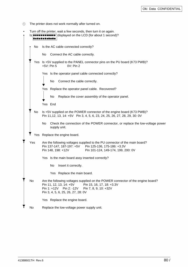
1 The printer does not work normally after turned on.
• Turn off the printer, wait a few seconds, then turn it on again.• Is displayed on the LCD (for about 1 second)?
• No Is the AC cable connected correctly?
No Connect the AC cable correctly.
• Yes Is +5V supplied to the PANEL connector pins on the PU board (K73 PWB)?+5V: Pin 5 0V: Pin 2
Yes Is the operator panel cable connected correctly?
No Connect the cable correctly.
Yes Replace the operator panel cable. Recovered?
No Replace the cover assembly of the operator panel.
Yes End
• No Is +5V supplied on the POWER connector of the engine board (K73 PWB)?Pin 11,12, 13, 14: +5V Pin 3, 4, 5, 6, 23, 24, 25, 26, 27, 28, 29, 30: 0V
No Check the connection of the POWER connector, or replace the low-voltage powersupply unit.
• Yes Replace the engine board.
• Yes Are the following voltages supplied to the PU connector of the main board?Pin 137-147, 187-197: +5V Pin 125-136, 175-186: +3.3VPin 148, 198: +12V Pin 101-124, 149-174, 199, 200: 0V
Yes Is the main board assy inserted correctly?
No Insert it correctly.
Yes Replace the main board.
• No Are the following voltages supplied on the POWER connector of the engine board?Pin 11, 12, 13, 14: +5V Pin 15, 16, 17, 18: +3.3VPin 1: +12V Pin 2: -12V Pin 7, 8, 9, 10: +32VPin 3, 4, 5, 6, 25, 26, 27, 28: 0V
Yes Replace the engine board.
• No Replace the low-voltage power supply unit.
41388601TH Rev.6 81 /
Oki Data CONFIDENTIAL
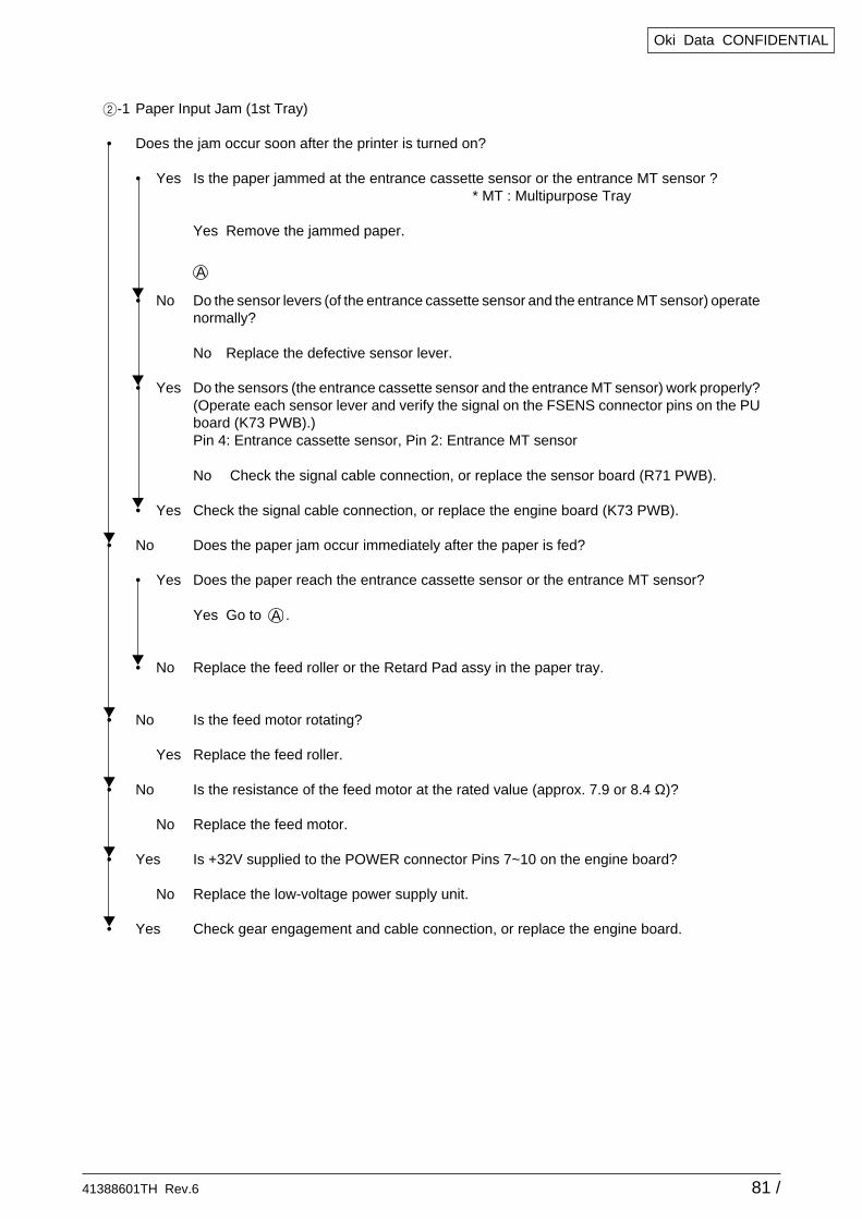
2-1 Paper Input Jam (1st Tray)
• Does the jam occur soon after the printer is turned on?
• Yes Is the paper jammed at the entrance cassette sensor or the entrance MT sensor ?* MT : Multipurpose Tray
Yes Remove the jammed paper.
• No Do the sensor levers (of the entrance cassette sensor and the entrance MT sensor) operatenormally?
No Replace the defective sensor lever.
• Yes Do the sensors (the entrance cassette sensor and the entrance MT sensor) work properly?(Operate each sensor lever and verify the signal on the FSENS connector pins on the PUboard (K73 PWB).)Pin 4: Entrance cassette sensor, Pin 2: Entrance MT sensor
No Check the signal cable connection, or replace the sensor board (R71 PWB).
• Yes Check the signal cable connection, or replace the engine board (K73 PWB).
• No Does the paper jam occur immediately after the paper is fed?
• Yes Does the paper reach the entrance cassette sensor or the entrance MT sensor?
Yes Go to .
• No Replace the feed roller or the Retard Pad assy in the paper tray.
• No Is the feed motor rotating?
Yes Replace the feed roller.
• No Is the resistance of the feed motor at the rated value (approx. 7.9 or 8.4 Ω)?
No Replace the feed motor.
• Yes Is +32V supplied to the POWER connector Pins 7~10 on the engine board?
No Replace the low-voltage power supply unit.
• Yes Check gear engagement and cable connection, or replace the engine board.
A
A
41388601TH Rev.6 82 /
Oki Data CONFIDENTIAL
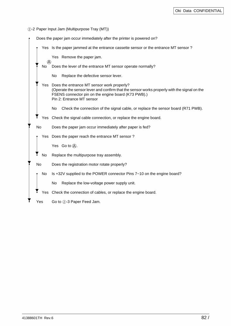
2-2 Paper Input Jam (Multipurpose Tray (MT))
• Does the paper jam occur immediately after the printer is powered on?
• Yes Is the paper jammed at the entrance cassette sensor or the entrance MT sensor ?
Yes Remove the paper jam.
• No Does the lever of the entrance MT sensor operate normally?
No Replace the defective sensor lever.
• Yes Does the entrance MT sensor work properly?(Operate the sensor lever and confirm that the sensor works properly with the signal on theFSENS connector pin on the engine board (K73 PWB).)Pin 2: Entrance MT sensor
No Check the connection of the signal cable, or replace the sensor board (R71 PWB).
• Yes Check the signal cable connection, or replace the engine board.
• No Does the paper jam occur immediately after paper is fed?
• Yes Does the paper reach the entrance MT sensor ?
Yes Go to .
• No Replace the multipurpose tray assembly.
• No Does the registration motor rotate properly?
• No Is +32V supplied to the POWER connector Pins 7~10 on the engine board?
No Replace the low-voltage power supply unit.
• Yes Check the connection of cables, or replace the engine board.
• Yes Go to 2-3 Paper Feed Jam.
A
A
41388601TH Rev.6 83 /
Oki Data CONFIDENTIAL
A
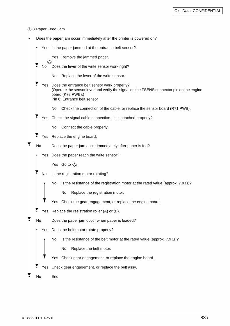
2-3 Paper Feed Jam
• Does the paper jam occur immediately after the printer is powered on?
• Yes Is the paper jammed at the entrance belt sensor?
Yes Remove the jammed paper.
• No Does the lever of the write sensor work right?
No Replace the lever of the write sensor.
• Yes Does the entrance belt sensor work properly?(Operate the sensor lever and verify the signal on the FSENS connector pin on the engineboard (K73 PWB).)Pin 6: Entrance belt sensor
No Check the connection of the cable, or replace the sensor board (R71 PWB).
• Yes Check the signal cable connection. Is it attached properly?
No Connect the cable properly.
• Yes Replace the engine board.
• No Does the paper jam occur immediately after paper is fed?
• Yes Does the paper reach the write sensor?
Yes Go to .
• No Is the registration motor rotating?
• No Is the resistance of the registration motor at the rated value (approx. 7.9 Ω)?
No Replace the registration motor.
• Yes Check the gear engagement, or replace the engine board.
• Yes Replace the resistration roller (A) or (B).
• No Does the paper jam occur when paper is loaded?
• Yes Does the belt motor rotate properly?
• No Is the resistance of the belt motor at the rated value (approx. 7.9 Ω)?
No Replace the belt motor.
• Yes Check gear engagement, or replace the engine board.
• Yes Check gear engagement, or replace the belt assy.
• No End
A
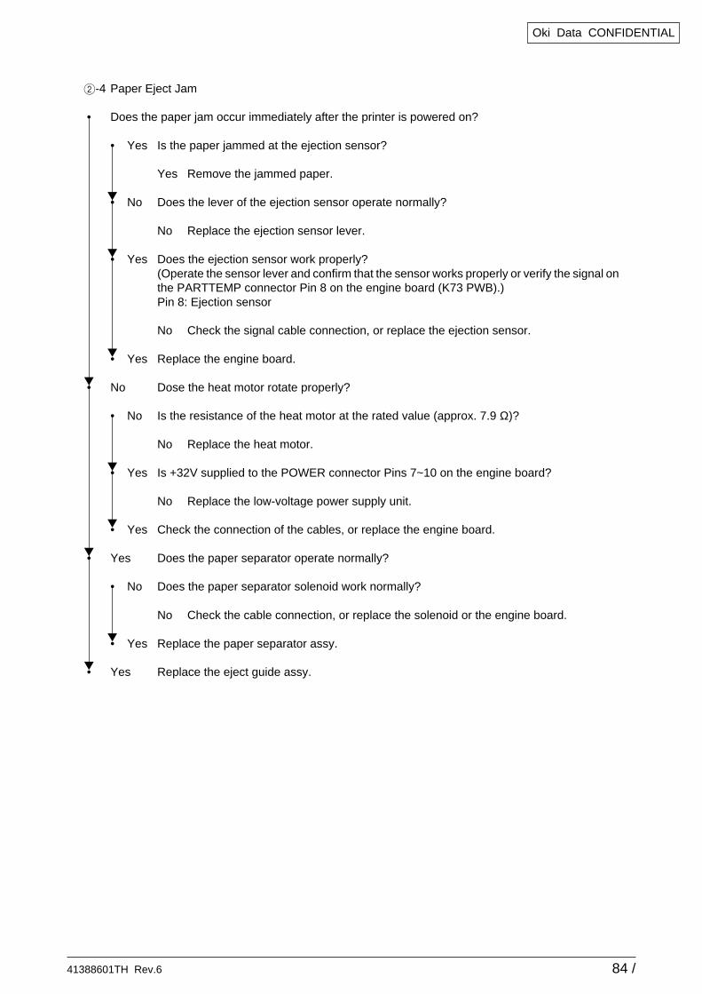
41388601TH Rev.6 84 /
Oki Data CONFIDENTIAL
2-4 Paper Eject Jam
• Does the paper jam occur immediately after the printer is powered on?
• Yes Is the paper jammed at the ejection sensor?
Yes Remove the jammed paper.
• No Does the lever of the ejection sensor operate normally?
No Replace the ejection sensor lever.
• Yes Does the ejection sensor work properly?(Operate the sensor lever and confirm that the sensor works properly or verify the signal onthe PARTTEMP connector Pin 8 on the engine board (K73 PWB).)Pin 8: Ejection sensor
No Check the signal cable connection, or replace the ejection sensor.
• Yes Replace the engine board.
• No Dose the heat motor rotate properly?
• No Is the resistance of the heat motor at the rated value (approx. 7.9 Ω)?
No Replace the heat motor.
• Yes Is +32V supplied to the POWER connector Pins 7~10 on the engine board?
No Replace the low-voltage power supply unit.
• Yes Check the connection of the cables, or replace the engine board.
• Yes Does the paper separator operate normally?
• No Does the paper separator solenoid work normally?
No Check the cable connection, or replace the solenoid or the engine board.
• Yes Replace the paper separator assy.
• Yes Replace the eject guide assy.
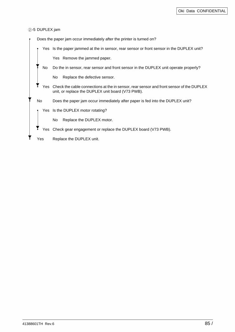
41388601TH Rev.6 85 /
Oki Data CONFIDENTIAL
2-5 DUPLEX jam
• Does the paper jam occur immediately after the printer is turned on?
• Yes Is the paper jammed at the in sensor, rear sensor or front sensor in the DUPLEX unit?
Yes Remove the jammed paper.
• No Do the in sensor, rear sensor and front sensor in the DUPLEX unit operate properly?
No Replace the defective sensor.
• Yes Check the cable connections at the in sensor, rear sensor and front sensor of the DUPLEXunit, or replace the DUPLEX unit board (V73 PWB).
• No Does the paper jam occur immediately after paper is fed into the DUPLEX unit?
• Yes Is the DUPLEX motor rotating?
No Replace the DUPLEX motor.
• Yes Check gear engagement or replace the DUPLEX board (V73 PWB).
• Yes Replace the DUPLEX unit.
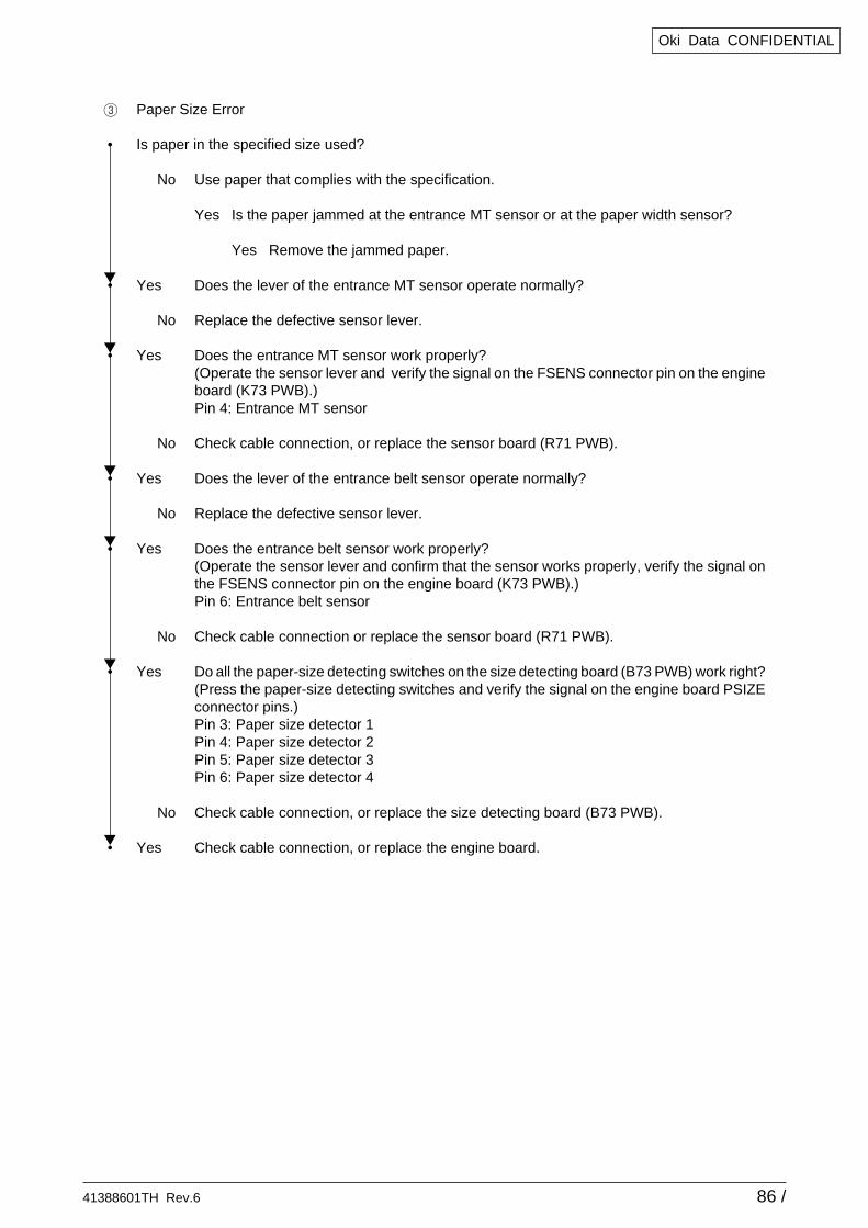
41388601TH Rev.6 86 /
Oki Data CONFIDENTIAL
3 Paper Size Error
• Is paper in the specified size used?
No Use paper that complies with the specification.
Yes Is the paper jammed at the entrance MT sensor or at the paper width sensor?
Yes Remove the jammed paper.
• Yes Does the lever of the entrance MT sensor operate normally?
No Replace the defective sensor lever.
• Yes Does the entrance MT sensor work properly?(Operate the sensor lever and verify the signal on the FSENS connector pin on the engineboard (K73 PWB).)Pin 4: Entrance MT sensor
No Check cable connection, or replace the sensor board (R71 PWB).
• Yes Does the lever of the entrance belt sensor operate normally?
No Replace the defective sensor lever.
• Yes Does the entrance belt sensor work properly?(Operate the sensor lever and confirm that the sensor works properly, verify the signal onthe FSENS connector pin on the engine board (K73 PWB).)Pin 6: Entrance belt sensor
No Check cable connection or replace the sensor board (R71 PWB).
• Yes Do all the paper-size detecting switches on the size detecting board (B73 PWB) work right?(Press the paper-size detecting switches and verify the signal on the engine board PSIZEconnector pins.)Pin 3: Paper size detector 1Pin 4: Paper size detector 2Pin 5: Paper size detector 3Pin 6: Paper size detector 4
No Check cable connection, or replace the size detecting board (B73 PWB).
• Yes Check cable connection, or replace the engine board.
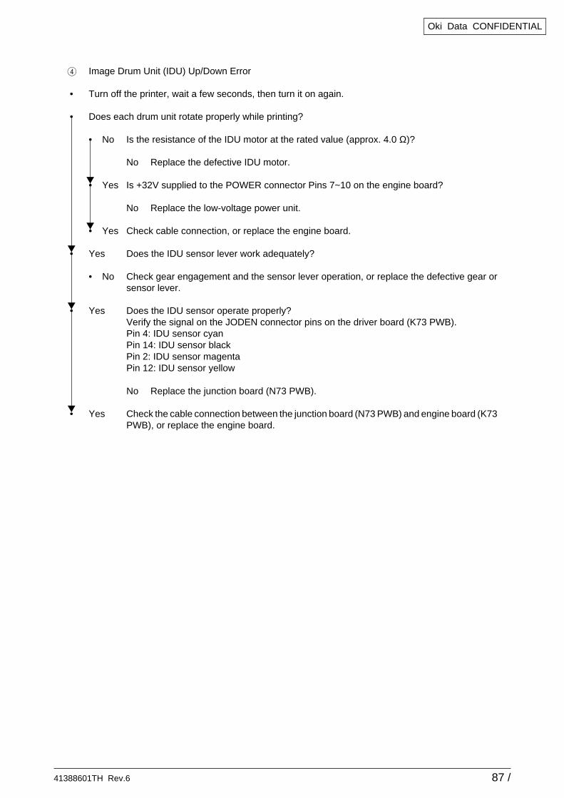
41388601TH Rev.6 87 /
Oki Data CONFIDENTIAL
4 Image Drum Unit (IDU) Up/Down Error
• Turn off the printer, wait a few seconds, then turn it on again.
• Does each drum unit rotate properly while printing?
• No Is the resistance of the IDU motor at the rated value (approx. 4.0 Ω)?
No Replace the defective IDU motor.
• Yes Is +32V supplied to the POWER connector Pins 7~10 on the engine board?
No Replace the low-voltage power unit.
• Yes Check cable connection, or replace the engine board.
• Yes Does the IDU sensor lever work adequately?
• No Check gear engagement and the sensor lever operation, or replace the defective gear orsensor lever.
• Yes Does the IDU sensor operate properly?Verify the signal on the JODEN connector pins on the driver board (K73 PWB).Pin 4: IDU sensor cyanPin 14: IDU sensor blackPin 2: IDU sensor magentaPin 12: IDU sensor yellow
No Replace the junction board (N73 PWB).
• Yes Check the cable connection between the junction board (N73 PWB) and engine board (K73PWB), or replace the engine board.
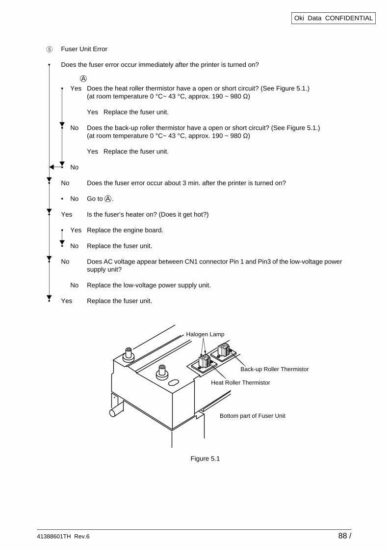
41388601TH Rev.6 88 /
Oki Data CONFIDENTIAL
5 Fuser Unit Error
• Does the fuser error occur immediately after the printer is turned on?
• Yes Does the heat roller thermistor have a open or short circuit? (See Figure 5.1.)(at room temperature 0 °C~ 43 °C, approx. 190 ~ 980 Ω)
Yes Replace the fuser unit.
• No Does the back-up roller thermistor have a open or short circuit? (See Figure 5.1.)(at room temperature 0 °C~ 43 °C, approx. 190 ~ 980 Ω)
Yes Replace the fuser unit.
• No
• No Does the fuser error occur about 3 min. after the printer is turned on?
• No Go to .
• Yes Is the fuser’s heater on? (Does it get hot?)
• Yes Replace the engine board.
• No Replace the fuser unit.
• No Does AC voltage appear between CN1 connector Pin 1 and Pin3 of the low-voltage powersupply unit?
No Replace the low-voltage power supply unit.
• Yes Replace the fuser unit.
Figure 5.1
A
A
Halogen Lamp
Back-up Roller Thermistor
Heat Roller Thermistor
Bottom part of Fuser Unit
41388601TH Rev.6 89 /
Oki Data CONFIDENTIAL
6 Fan Motor Error
• Does the fan of the low-voltage power supply unit rotate after the printer is turned on?
• Yes Does the error recur after the fan of the low-voltage power supply unit has been replaced?
• Yes Replace the low-voltage power supply unit.
• No End
• Yes Does the engine board fan rotate after the printer is turned on?
• No Is +32V supplied to the FAN connector Pin 1 on the engine board (K73 PWB)?
• No Is +32V supplied to the POWER connector pins on the engine board (K73 PWB)?+32V: Pin 7, 8, 9, 10
No Check cable connection or replace the low-voltage power supply unit.
• Yes Replace the engine board.
• Yes Replace the fan of the engine board.
• Yes Does the fuser fan rotate after the printer is turned on?
• No Is +32V supplied to the JOBOFF connector Pin 5 on the engine board (K73 PWB)?
• No Is +32V supplied to the POWER connector pins on the engine board (K73 PWB)?+32V: Pin 7, 8, 9, 10
No Check cable connection, or replace the low-voltage power supply unit.
• Yes Replace the engine board.
• Yes Replace the fuser fan.
• Yes End
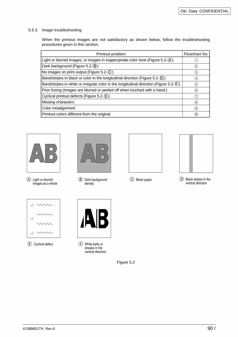
41388601TH Rev.6 90 /
Oki Data CONFIDENTIAL
Printout problem Flowchart No.
Light or blurred images, or images in inappropriate color tone (Figure 5.2- A ) 1
Dark background (Figure 5.2- B ) 2
No images on print output (Figure 5.2- C ) 3
Band/stripes in black or color in the longitudinal direction (Figure 5.2- D ) 4
Band/stripes in white or irregular color in the longitudinal direction (Figure 5.2- F ) 5
Poor fusing (Images are blurred or peeled off when touched with a hand.) 6
Cyclical printout defects (Figure 5.2- E ) 7
Missing characters 8
Color misalignment 9
Printout colors different from the original 0
5.5.3 Image troubleshooting
When the printout images are not satisfactory as shown below, follow the troubleshootingprocedures given in this section.
Figure 5.2
Light or blurredimages as a whole
A Black stripes in thevertical direction
DDark backgrounddensity
B
Cyclical defectE
Blank paperC
White belts orstreaks in the vertical direction
F
41388601TH Rev.6 91 /
Oki Data CONFIDENTIAL
1 Light or blurred images or images in inappropriate color tone on the whole printout area(Figure 5.2- A )
• Is toner low? (Is the message "Toner Low" displayed?)
Yes Supply toner.
• No Is the specified paper used?
No Use the specified paper.
• Yes Is the lens of the LED head dirty?
Yes Clean the LED head lens.
• No Is each LED head assy connected properly to the junction board (Y71 PWB) and engineboard (K73 PWB)?
No Check the cable connection (between each LED head and the engine board) and connectthe cable between the LED head and the engine board properly.
• Yes Is +3.8V supplied to the following POWER connector pins on the junction board(Y71 PWB)?+3.8V: Pins 1, 2, 3, 4, 5, 6, 7 and 8
• Yes Is +3.8V supplied to each LED head assy from the junction board (Y73 PWB)?YPOW connector Pin 3: LED head assy yellowMPOW connector Pin 3: LED head assy magentaCPOW connector Pin 3: LED head assy cyanBPOW connector Pin 3: LED head assy black
No Replace the junction board (Y71 PWB).
• Yes Check the cable connection, or replace the LED head assy.
• No Check the cable connection, or replace the low-voltage power supply unit. Recovered?
Yes End
• No Is +32V supplied to the POWER connector pins on the engine board (K73 PWB)?+32V: Pins 7, 8, 9 and 10
No Check cable connection, or replace the low-voltage power supply unit.
• Yes Is +32V supplied to the HVOLT connector Pin 5 on the engine board (K73 PWB)?
No Replace the engine board.
• Yes Check the cable connection, replace the high-voltage power unit, or belt cassette assembly.Recovered?
Yes End
• No Is each ID terminal connected correctly to the contact assembly? (See Figure 5.3.)
No Connect the ID terminals with the contact assembly correctly.
• Yes Replace the ID unit.
Notes: 1. When replacing the engine board (K73 PWB), demount the EEPROM chip from the oldengine board and remount it on the new one.
2. In case the EEPROM chip is not replaced, see Item (2) in Sec. 5.5.2.
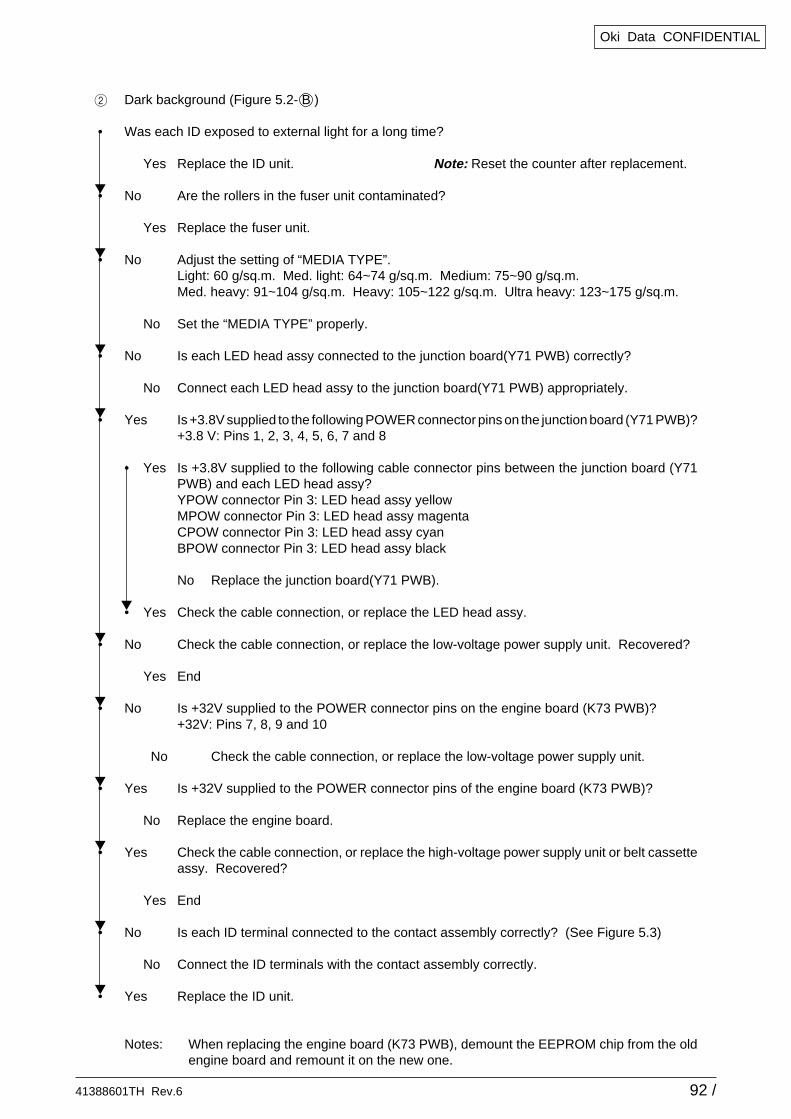
41388601TH Rev.6 92 /
Oki Data CONFIDENTIAL
2 Dark background (Figure 5.2- B )
• Was each ID exposed to external light for a long time?
Yes Replace the ID unit. Note: Reset the counter after replacement.
• No Are the rollers in the fuser unit contaminated?
Yes Replace the fuser unit.
• No Adjust the setting of “MEDIA TYPE”.Light: 60 g/sq.m. Med. light: 64~74 g/sq.m. Medium: 75~90 g/sq.m.Med. heavy: 91~104 g/sq.m. Heavy: 105~122 g/sq.m. Ultra heavy: 123~175 g/sq.m.
No Set the “MEDIA TYPE” properly.
• No Is each LED head assy connected to the junction board(Y71 PWB) correctly?
No Connect each LED head assy to the junction board(Y71 PWB) appropriately.
• Yes Is +3.8V supplied to the following POWER connector pins on the junction board (Y71 PWB)?+3.8 V: Pins 1, 2, 3, 4, 5, 6, 7 and 8
• Yes Is +3.8V supplied to the following cable connector pins between the junction board (Y71PWB) and each LED head assy?YPOW connector Pin 3: LED head assy yellowMPOW connector Pin 3: LED head assy magentaCPOW connector Pin 3: LED head assy cyanBPOW connector Pin 3: LED head assy black
No Replace the junction board(Y71 PWB).
• Yes Check the cable connection, or replace the LED head assy.
• No Check the cable connection, or replace the low-voltage power supply unit. Recovered?
Yes End
• No Is +32V supplied to the POWER connector pins on the engine board (K73 PWB)?+32V: Pins 7, 8, 9 and 10
No Check the cable connection, or replace the low-voltage power supply unit.
• Yes Is +32V supplied to the POWER connector pins of the engine board (K73 PWB)?
No Replace the engine board.
• Yes Check the cable connection, or replace the high-voltage power supply unit or belt cassetteassy. Recovered?
Yes End
• No Is each ID terminal connected to the contact assembly correctly? (See Figure 5.3)
No Connect the ID terminals with the contact assembly correctly.
• Yes Replace the ID unit.
Notes: When replacing the engine board (K73 PWB), demount the EEPROM chip from the oldengine board and remount it on the new one.
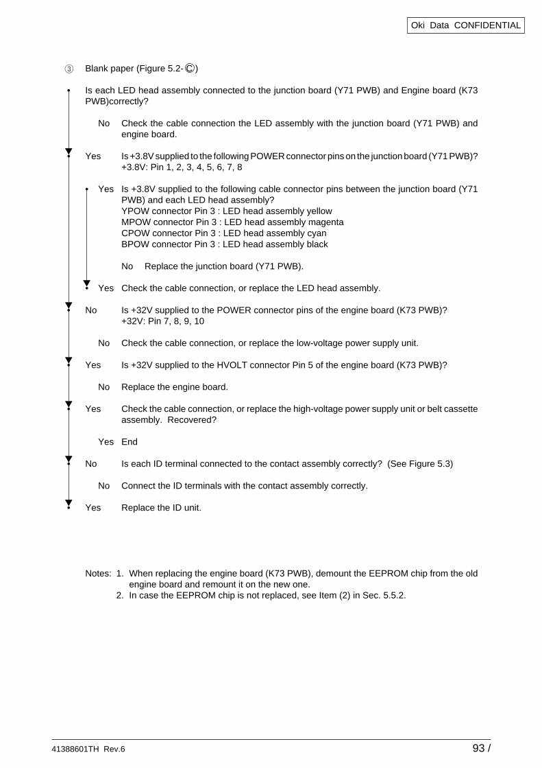
41388601TH Rev.6 93 /
Oki Data CONFIDENTIAL
3 Blank paper (Figure 5.2- C )
• Is each LED head assembly connected to the junction board (Y71 PWB) and Engine board (K73PWB)correctly?
No Check the cable connection the LED assembly with the junction board (Y71 PWB) andengine board.
• Yes Is +3.8V supplied to the following POWER connector pins on the junction board (Y71 PWB)?+3.8V: Pin 1, 2, 3, 4, 5, 6, 7, 8
• Yes Is +3.8V supplied to the following cable connector pins between the junction board (Y71PWB) and each LED head assembly?YPOW connector Pin 3 : LED head assembly yellowMPOW connector Pin 3 : LED head assembly magentaCPOW connector Pin 3 : LED head assembly cyanBPOW connector Pin 3 : LED head assembly black
No Replace the junction board (Y71 PWB).
• Yes Check the cable connection, or replace the LED head assembly.
• No Is +32V supplied to the POWER connector pins of the engine board (K73 PWB)?+32V: Pin 7, 8, 9, 10
No Check the cable connection, or replace the low-voltage power supply unit.
• Yes Is +32V supplied to the HVOLT connector Pin 5 of the engine board (K73 PWB)?
No Replace the engine board.
• Yes Check the cable connection, or replace the high-voltage power supply unit or belt cassetteassembly. Recovered?
Yes End
• No Is each ID terminal connected to the contact assembly correctly? (See Figure 5.3)
No Connect the ID terminals with the contact assembly correctly.
• Yes Replace the ID unit.
Notes: 1. When replacing the engine board (K73 PWB), demount the EEPROM chip from the oldengine board and remount it on the new one.
2. In case the EEPROM chip is not replaced, see Item (2) in Sec. 5.5.2.
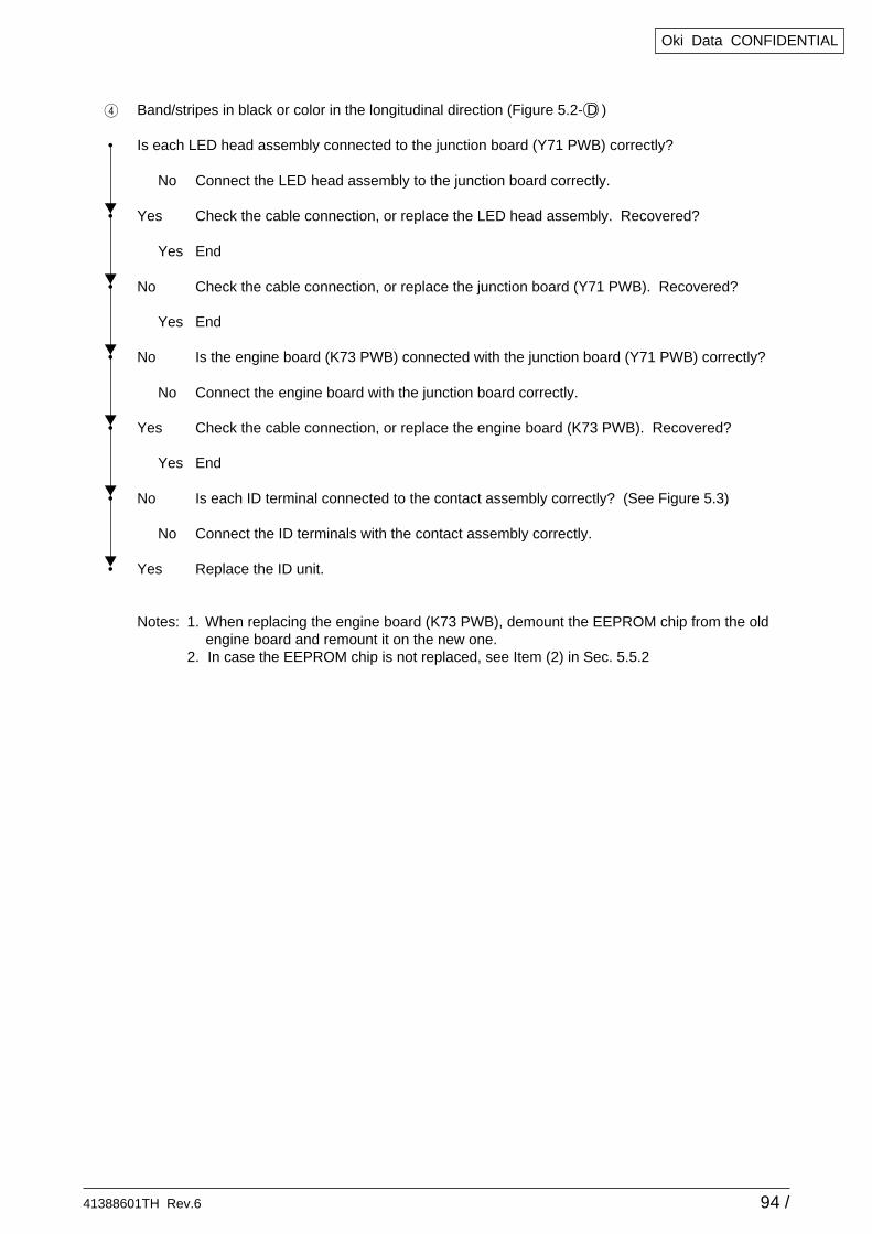
41388601TH Rev.6 94 /
Oki Data CONFIDENTIAL
4 Band/stripes in black or color in the longitudinal direction (Figure 5.2- D )
• Is each LED head assembly connected to the junction board (Y71 PWB) correctly?
No Connect the LED head assembly to the junction board correctly.
• Yes Check the cable connection, or replace the LED head assembly. Recovered?
Yes End
• No Check the cable connection, or replace the junction board (Y71 PWB). Recovered?
Yes End
• No Is the engine board (K73 PWB) connected with the junction board (Y71 PWB) correctly?
No Connect the engine board with the junction board correctly.
• Yes Check the cable connection, or replace the engine board (K73 PWB). Recovered?
Yes End
• No Is each ID terminal connected to the contact assembly correctly? (See Figure 5.3)
No Connect the ID terminals with the contact assembly correctly.
• Yes Replace the ID unit.
Notes: 1. When replacing the engine board (K73 PWB), demount the EEPROM chip from the oldengine board and remount it on the new one.
2. In case the EEPROM chip is not replaced, see Item (2) in Sec. 5.5.2
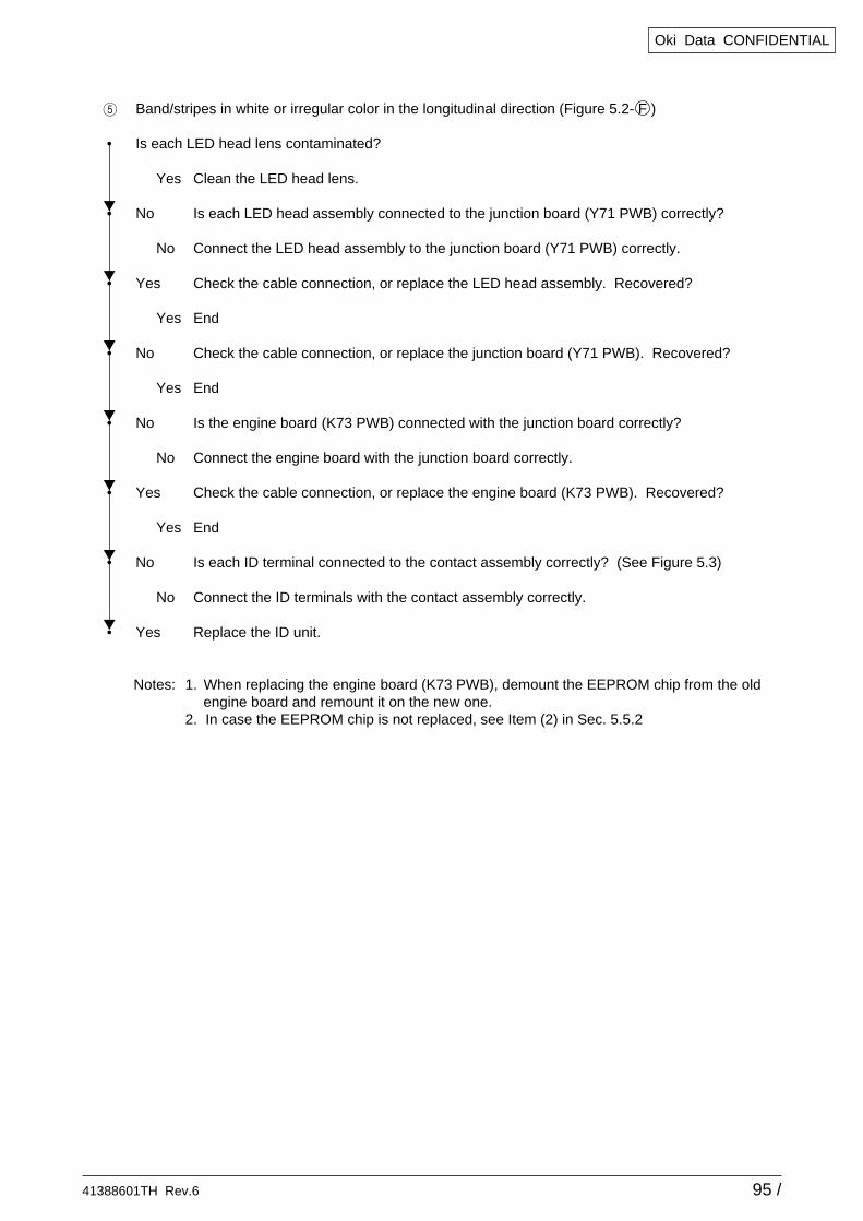
41388601TH Rev.6 95 /
Oki Data CONFIDENTIAL
5 Band/stripes in white or irregular color in the longitudinal direction (Figure 5.2- F )
• Is each LED head lens contaminated?
Yes Clean the LED head lens.
• No Is each LED head assembly connected to the junction board (Y71 PWB) correctly?
No Connect the LED head assembly to the junction board (Y71 PWB) correctly.
• Yes Check the cable connection, or replace the LED head assembly. Recovered?
Yes End
• No Check the cable connection, or replace the junction board (Y71 PWB). Recovered?
Yes End
• No Is the engine board (K73 PWB) connected with the junction board correctly?
No Connect the engine board with the junction board correctly.
• Yes Check the cable connection, or replace the engine board (K73 PWB). Recovered?
Yes End
• No Is each ID terminal connected to the contact assembly correctly? (See Figure 5.3)
No Connect the ID terminals with the contact assembly correctly.
• Yes Replace the ID unit.
Notes: 1. When replacing the engine board (K73 PWB), demount the EEPROM chip from the oldengine board and remount it on the new one.
2. In case the EEPROM chip is not replaced, see Item (2) in Sec. 5.5.2
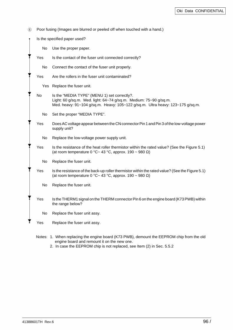
41388601TH Rev.6 96 /
Oki Data CONFIDENTIAL
6 Poor fusing (Images are blurred or peeled off when touched with a hand.)
• Is the specified paper used?
No Use the proper paper.
• Yes Is the contact of the fuser unit connected correctly?
No Connect the contact of the fuser unit properly.
• Yes Are the rollers in the fuser unit contaminated?
Yes Replace the fuser unit.
• No Is the “MEDIA TYPE” (MENU 1) set correctly?.Light: 60 g/sq.m. Med. light: 64~74 g/sq.m. Medium: 75~90 g/sq.m.Med. heavy: 91~104 g/sq.m. Heavy: 105~122 g/sq.m. Ultra heavy: 123~175 g/sq.m.
No Set the proper “MEDIA TYPE”.
• Yes Does AC voltage appear between the CN connector Pin 1 and Pin 3 of the low-voltage powersupply unit?
No Replace the low-voltage power supply unit.
• Yes Is the resistance of the heat roller thermistor within the rated value? (See the Figure 5.1)(at room temperature 0 °C~ 43 °C, approx. 190 ~ 980 Ω)
No Replace the fuser unit.
• Yes Is the resistance of the back-up roller thermistor within the rated value? (See the Figure 5.1)(at room temperature 0 °C~ 43 °C, approx. 190 ~ 980 Ω)
No Replace the fuser unit.
• Yes Is the THERM1 signal on the THERM connector Pin 6 on the engine board (K73 PWB) withinthe range below?
No Replace the fuser unit assy.
• Yes Replace the fuser unit assy.
Notes: 1. When replacing the engine board (K73 PWB), demount the EEPROM chip from the oldengine board and remount it on the new one.
2. In case the EEPROM chip is not replaced, see Item (2) in Sec. 5.5.2
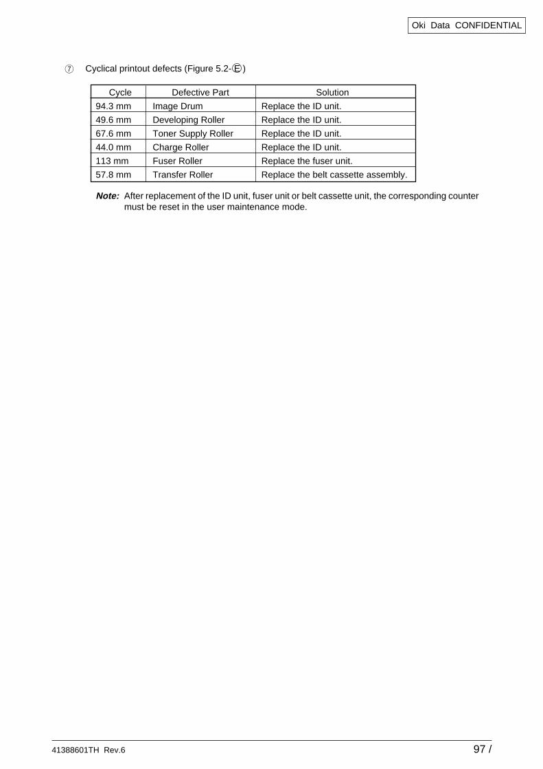
41388601TH Rev.6 97 /
Oki Data CONFIDENTIAL
7 Cyclical printout defects (Figure 5.2- E )
Note: After replacement of the ID unit, fuser unit or belt cassette unit, the corresponding countermust be reset in the user maintenance mode.
Cycle Defective Part Solution
94.3 mm Image Drum Replace the ID unit.
49.6 mm Developing Roller Replace the ID unit.
67.6 mm Toner Supply Roller Replace the ID unit.
44.0 mm Charge Roller Replace the ID unit.
113 mm Fuser Roller Replace the fuser unit.
57.8 mm Transfer Roller Replace the belt cassette assembly.
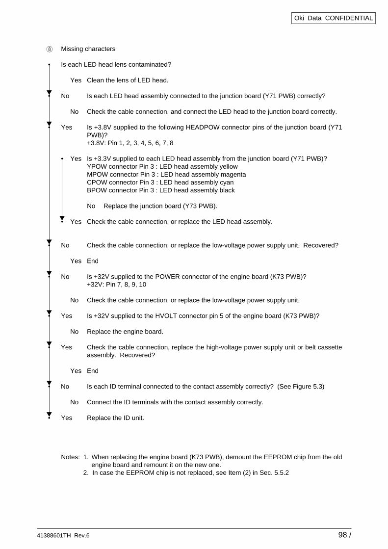
41388601TH Rev.6 98 /
Oki Data CONFIDENTIAL
8 Missing characters
• Is each LED head lens contaminated?
Yes Clean the lens of LED head.
• No Is each LED head assembly connected to the junction board (Y71 PWB) correctly?
No Check the cable connection, and connect the LED head to the junction board correctly.
• Yes Is +3.8V supplied to the following HEADPOW connector pins of the junction board (Y71PWB)?+3.8V: Pin 1, 2, 3, 4, 5, 6, 7, 8
• Yes Is +3.3V supplied to each LED head assembly from the junction board (Y71 PWB)?YPOW connector Pin 3 : LED head assembly yellowMPOW connector Pin 3 : LED head assembly magentaCPOW connector Pin 3 : LED head assembly cyanBPOW connector Pin 3 : LED head assembly black
No Replace the junction board (Y73 PWB).
• Yes Check the cable connection, or replace the LED head assembly.
• No Check the cable connection, or replace the low-voltage power supply unit. Recovered?
Yes End
• No Is +32V supplied to the POWER connector of the engine board (K73 PWB)?+32V: Pin 7, 8, 9, 10
No Check the cable connection, or replace the low-voltage power supply unit.
• Yes Is +32V supplied to the HVOLT connector pin 5 of the engine board (K73 PWB)?
No Replace the engine board.
• Yes Check the cable connection, replace the high-voltage power supply unit or belt cassetteassembly. Recovered?
Yes End
• No Is each ID terminal connected to the contact assembly correctly? (See Figure 5.3)
No Connect the ID terminals with the contact assembly correctly.
• Yes Replace the ID unit.
Notes: 1. When replacing the engine board (K73 PWB), demount the EEPROM chip from the oldengine board and remount it on the new one.
2. In case the EEPROM chip is not replaced, see Item (2) in Sec. 5.5.2
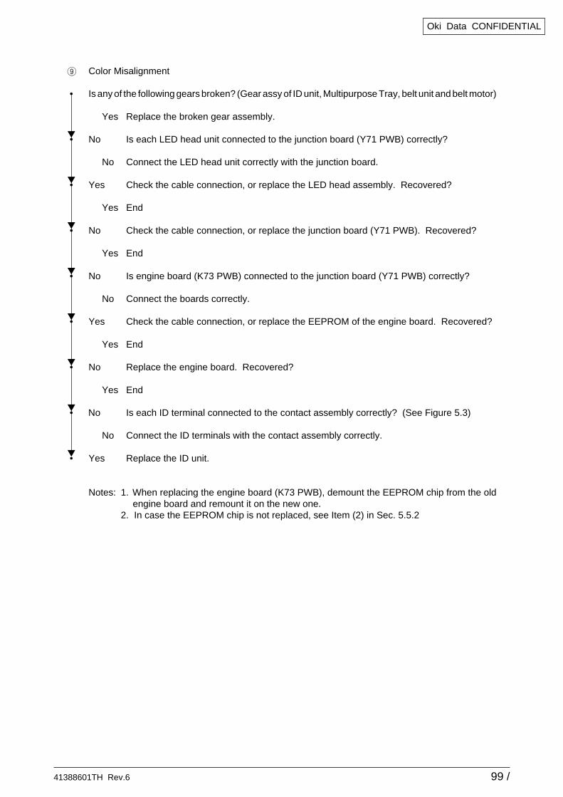
41388601TH Rev.6 99 /
Oki Data CONFIDENTIAL
9 Color Misalignment
• Is any of the following gears broken? (Gear assy of ID unit, Multipurpose Tray, belt unit and belt motor)
Yes Replace the broken gear assembly.
• No Is each LED head unit connected to the junction board (Y71 PWB) correctly?
No Connect the LED head unit correctly with the junction board.
• Yes Check the cable connection, or replace the LED head assembly. Recovered?
Yes End
• No Check the cable connection, or replace the junction board (Y71 PWB). Recovered?
Yes End
• No Is engine board (K73 PWB) connected to the junction board (Y71 PWB) correctly?
No Connect the boards correctly.
• Yes Check the cable connection, or replace the EEPROM of the engine board. Recovered?
Yes End
• No Replace the engine board. Recovered?
Yes End
• No Is each ID terminal connected to the contact assembly correctly? (See Figure 5.3)
No Connect the ID terminals with the contact assembly correctly.
• Yes Replace the ID unit.
Notes: 1. When replacing the engine board (K73 PWB), demount the EEPROM chip from the oldengine board and remount it on the new one.
2. In case the EEPROM chip is not replaced, see Item (2) in Sec. 5.5.2
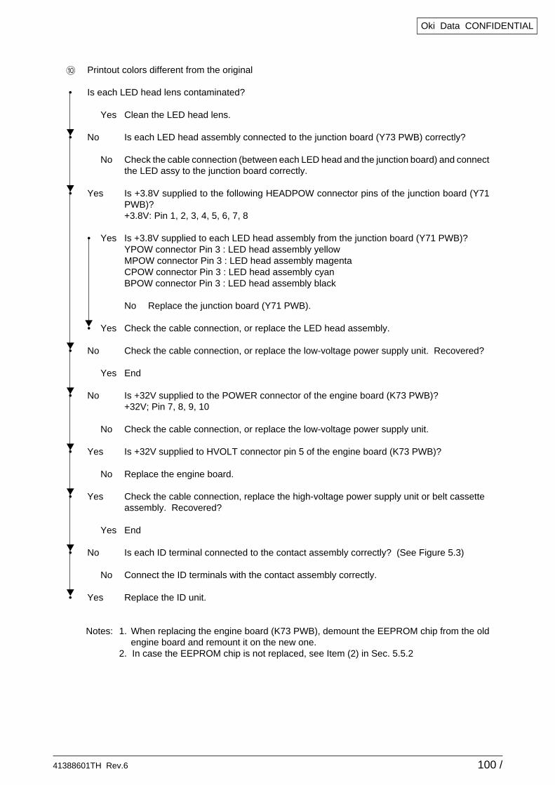
41388601TH Rev.6 100 /
Oki Data CONFIDENTIAL
0 Printout colors different from the original
• Is each LED head lens contaminated?
Yes Clean the LED head lens.
• No Is each LED head assembly connected to the junction board (Y73 PWB) correctly?
No Check the cable connection (between each LED head and the junction board) and connectthe LED assy to the junction board correctly.
• Yes Is +3.8V supplied to the following HEADPOW connector pins of the junction board (Y71PWB)?+3.8V: Pin 1, 2, 3, 4, 5, 6, 7, 8
• Yes Is +3.8V supplied to each LED head assembly from the junction board (Y71 PWB)?YPOW connector Pin 3 : LED head assembly yellowMPOW connector Pin 3 : LED head assembly magentaCPOW connector Pin 3 : LED head assembly cyanBPOW connector Pin 3 : LED head assembly black
No Replace the junction board (Y71 PWB).
• Yes Check the cable connection, or replace the LED head assembly.
• No Check the cable connection, or replace the low-voltage power supply unit. Recovered?
Yes End
• No Is +32V supplied to the POWER connector of the engine board (K73 PWB)?+32V; Pin 7, 8, 9, 10
No Check the cable connection, or replace the low-voltage power supply unit.
• Yes Is +32V supplied to HVOLT connector pin 5 of the engine board (K73 PWB)?
No Replace the engine board.
• Yes Check the cable connection, replace the high-voltage power supply unit or belt cassetteassembly. Recovered?
Yes End
• No Is each ID terminal connected to the contact assembly correctly? (See Figure 5.3)
No Connect the ID terminals with the contact assembly correctly.
• Yes Replace the ID unit.
Notes: 1. When replacing the engine board (K73 PWB), demount the EEPROM chip from the oldengine board and remount it on the new one.
2. In case the EEPROM chip is not replaced, see Item (2) in Sec. 5.5.2
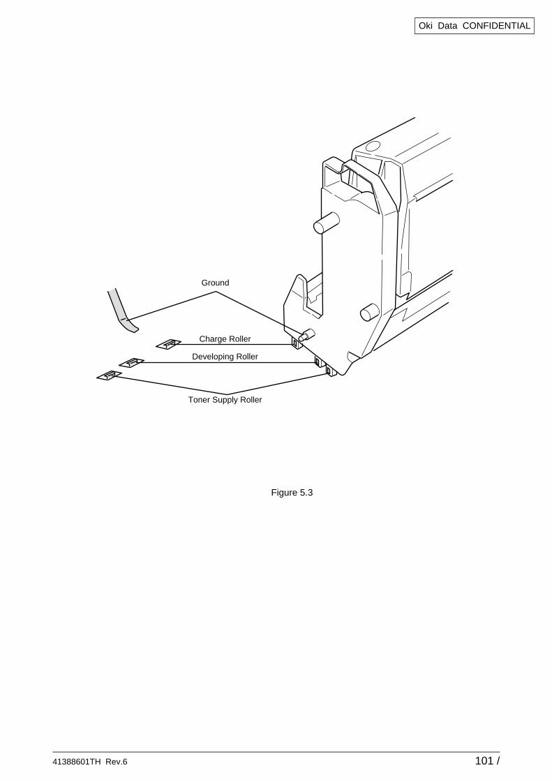
41388601TH Rev.6 101 /
Oki Data CONFIDENTIAL
Figure 5.3
Ground
Charge Roller
Developing Roller
Toner Supply Roller
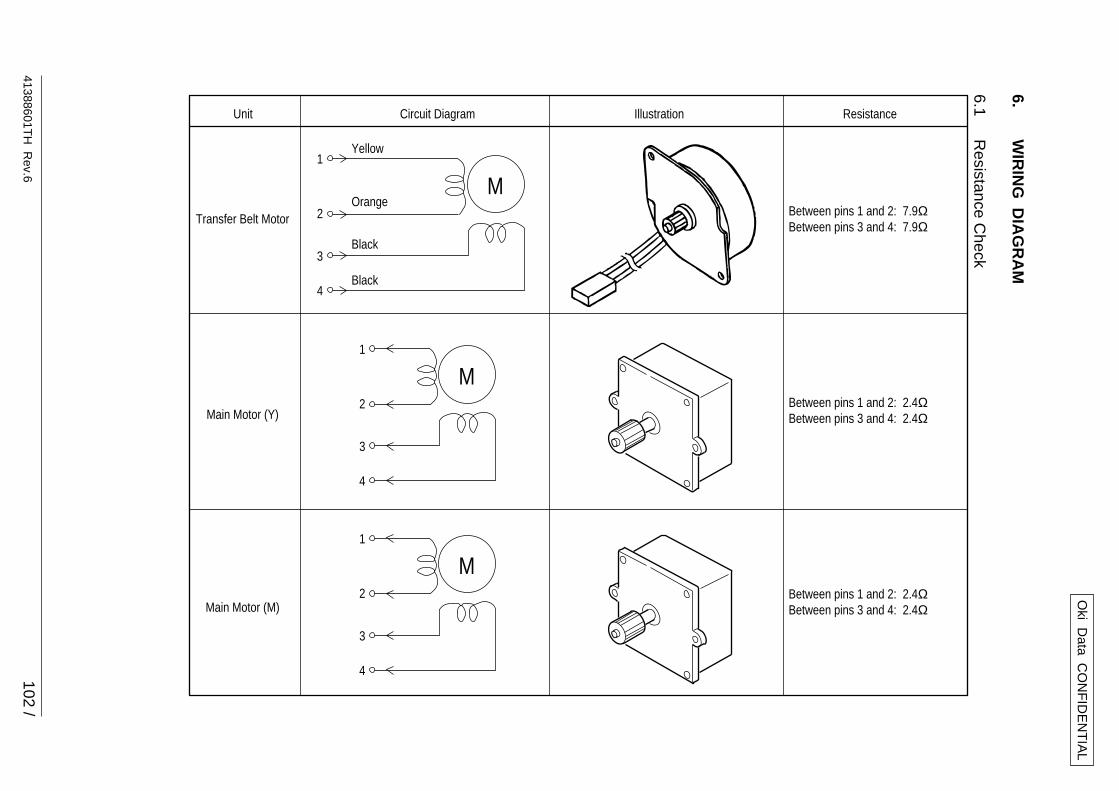
41388601TH
Rev.6
102 /
Oki D
ata CO
NF
IDE
NT
IAL
6.W
IRIN
G D
IAG
RA
M
6.1R
esistance Check
Unit Circuit Diagram Illustration Resistance
Between pins 1 and 2: 7.9ΩBetween pins 3 and 4: 7.9Ω
Between pins 1 and 2: 2.4ΩBetween pins 3 and 4: 2.4Ω
Between pins 1 and 2: 2.4ΩBetween pins 3 and 4: 2.4Ω
Transfer Belt Motor
Main Motor (Y)
Main Motor (M)
Yellow
Orange
Black
Black
M1
2
3
4
M1
2
3
4
M1
2
3
4
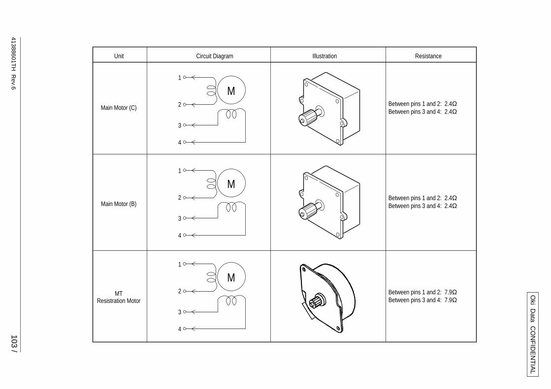
41388601TH
Rev.6
103 /
Oki D
ata CO
NF
IDE
NT
IAL
Unit Circuit Diagram Illustration Resistance
Between pins 1 and 2: 2.4ΩBetween pins 3 and 4: 2.4Ω
Between pins 1 and 2: 2.4ΩBetween pins 3 and 4: 2.4Ω
Between pins 1 and 2: 7.9ΩBetween pins 3 and 4: 7.9Ω
Main Motor (C)
Main Motor (B)
MTResistration Motor
M1
2
3
4
M1
2
3
4
M1
2
3
4
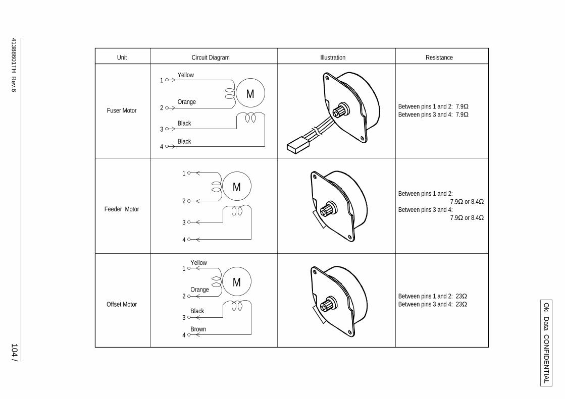
41388601TH
Rev.6
104 /
Oki D
ata CO
NF
IDE
NT
IAL
Yellow
Orange
Black
Black
Yellow
Orange
Black
Brown
M1
2
3
4
Unit Circuit Diagram Illustration Resistance
Between pins 1 and 2: 7.9ΩBetween pins 3 and 4: 7.9Ω
Between pins 1 and 2: 23ΩBetween pins 3 and 4: 23Ω
Between pins 1 and 2: 7.9Ω or 8.4ΩBetween pins 3 and 4: 7.9Ω or 8.4Ω
Fuser Motor
Feeder Motor
Offset Motor
M1
2
3
4
M1
2
3
4
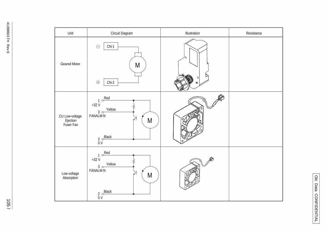
41388601TH
Rev.6
105 /
Oki D
ata CO
NF
IDE
NT
IAL
Unit Circuit Diagram Illustration Resistance
Geared Motor
Low-voltageAbsorption
CU Low-voltage EjectionFuser Fan
- CN-1
+
M
CN-2
Red
Black
+32 V1
FANALM-N3
0 V2
M
Yellow
Red
Black
+32 V1
FANALM-N3
0 V2
M
Yellow
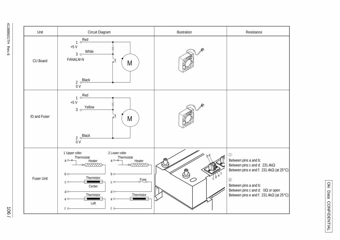
41388601TH
Rev.6
106 /
Oki D
ata CO
NF
IDE
NT
IAL
c d e f
ab
Unit Circuit Diagram Illustration Resistance
a
1 Upper roller 12 Lower roller
b
Thermostat ThermostatHeater Between pins a and b:
Between pins c and d: 231.4kΩ Between pins e and f: 231.4kΩ (at 25°C)
2
Between pins a and b:Between pins c and d: 0Ω or openBetween pins e and f: 231.4kΩ (at 25°C)
Fuser Unit
a
b
Heater
e
f
Thermistor
c
d
Fuse
e
f
Thermistor
c
d
Thermistor
Left
Center
ID and Fuser
Red
Black
+5 V1
3
0 V2
M
Yellow
CU Board
Red
Black
+5 V
FANALM-N
1
3
0 V2
M
White
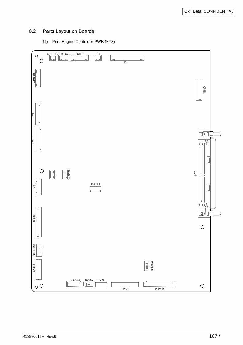
41388601TH Rev.6 107 /
Oki Data CONFIDENTIAL
6.2 Parts Layout on Boards
(1) Print Engine Controller PWB (K73)
CPUFL1
FSENS
OPTN
JOD
ENPARTTEM
PR
SNS
DUPLEX DUCOV PSIZE
HVOLT POWER
BELTSNS
CU
IF
TR10P
REG
BELTHET
SHUTTER HOPFFFRPUCL RCL
ID
CO
VOPN
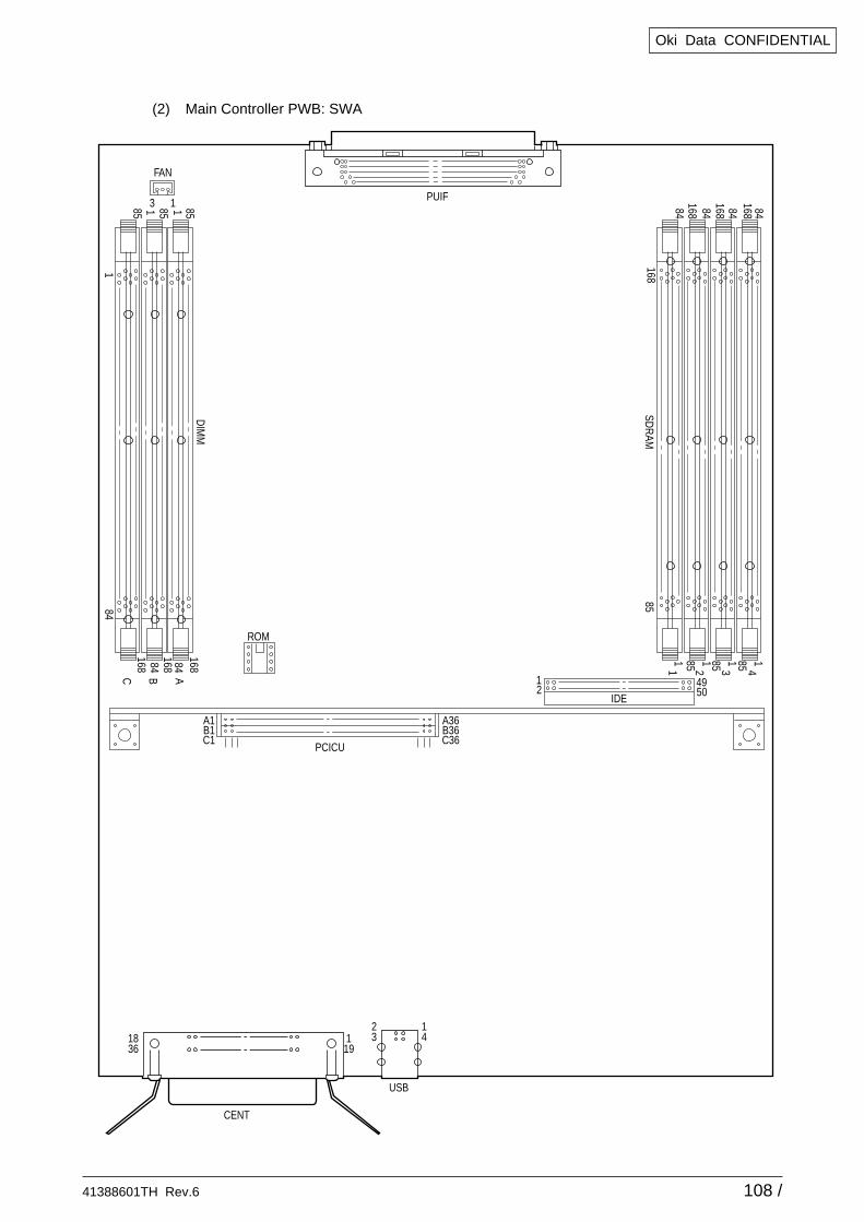
41388601TH Rev.6 108 /
Oki Data CONFIDENTIAL
(2) Main Controller PWB: SWA
PUIF
FAN
3
84
84 84
1
1 185168
C
185168
B
85168
A
DIM
M
842
85168
168
168
168841 85 1 85 1 85 1
1
843
844
SDR
AM
ROM
CENT
USB
2318
361
19
14
PCICU
A1B1C1
A36B36C36
IDE
12
4950
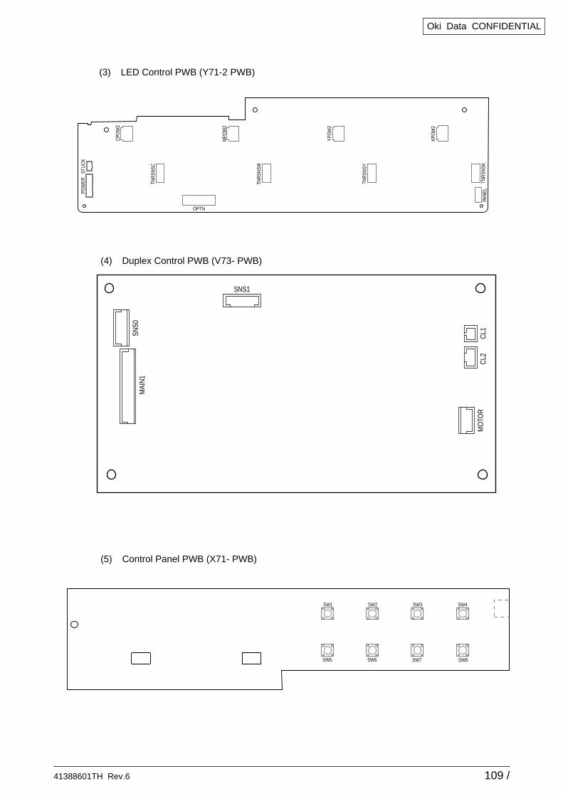
41388601TH Rev.6 109 /
Oki Data CONFIDENTIAL
(3) LED Control PWB (Y71-2 PWB)PO
WER
STU
CK
CPO
W2
MPO
W2
YPO
W2
TNR
SNSC
TNR
SNSM
TNR
SNSY
OPTN
KPO
W2
TNR
SNSK
PAN
EL
(4) Duplex Control PWB (V73- PWB)
SNS0
MAI
N1
SNS1
CL1
CL2
MO
TOR
(5) Control Panel PWB (X71- PWB)
SW4
SW8
SW3
SW7
SW2
SW6
SW1
SW5
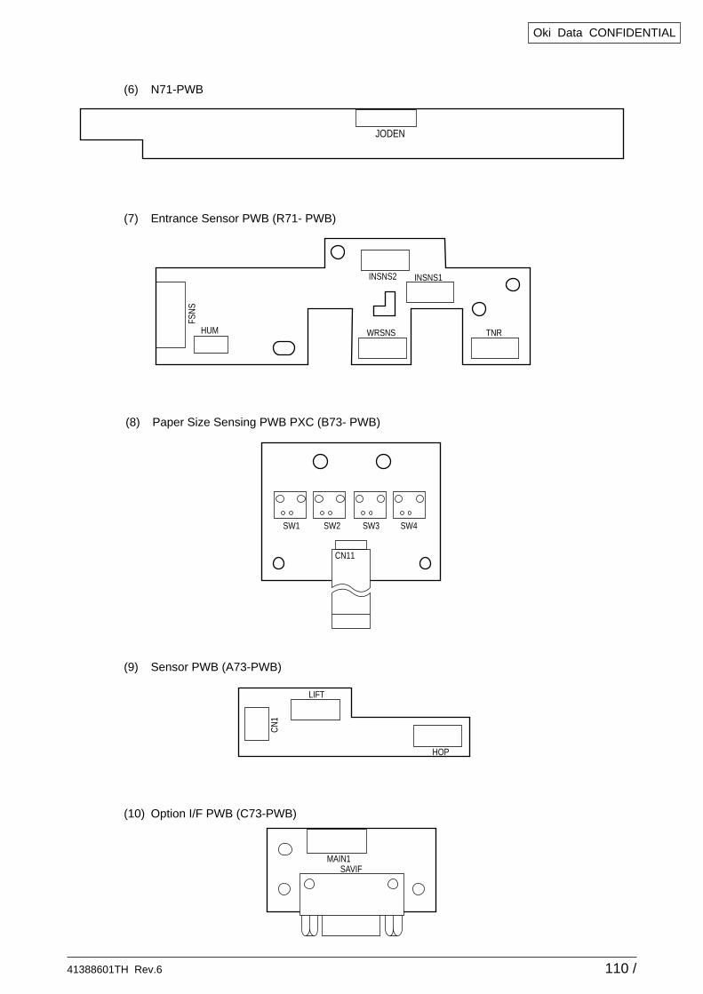
41388601TH Rev.6 110 /
Oki Data CONFIDENTIAL
(6) N71-PWB
JODEN
(7) Entrance Sensor PWB (R71- PWB)
HUM WRSNS
INSNS1INSNS2
TNR
FSN
S
(8) Paper Size Sensing PWB PXC (B73- PWB)
CN11
SW1 SW2 SW3 SW4
(9) Sensor PWB (A73-PWB)
(10) Option I/F PWB (C73-PWB)
LIFT
HOP
CN
1
MAIN1SAVIF
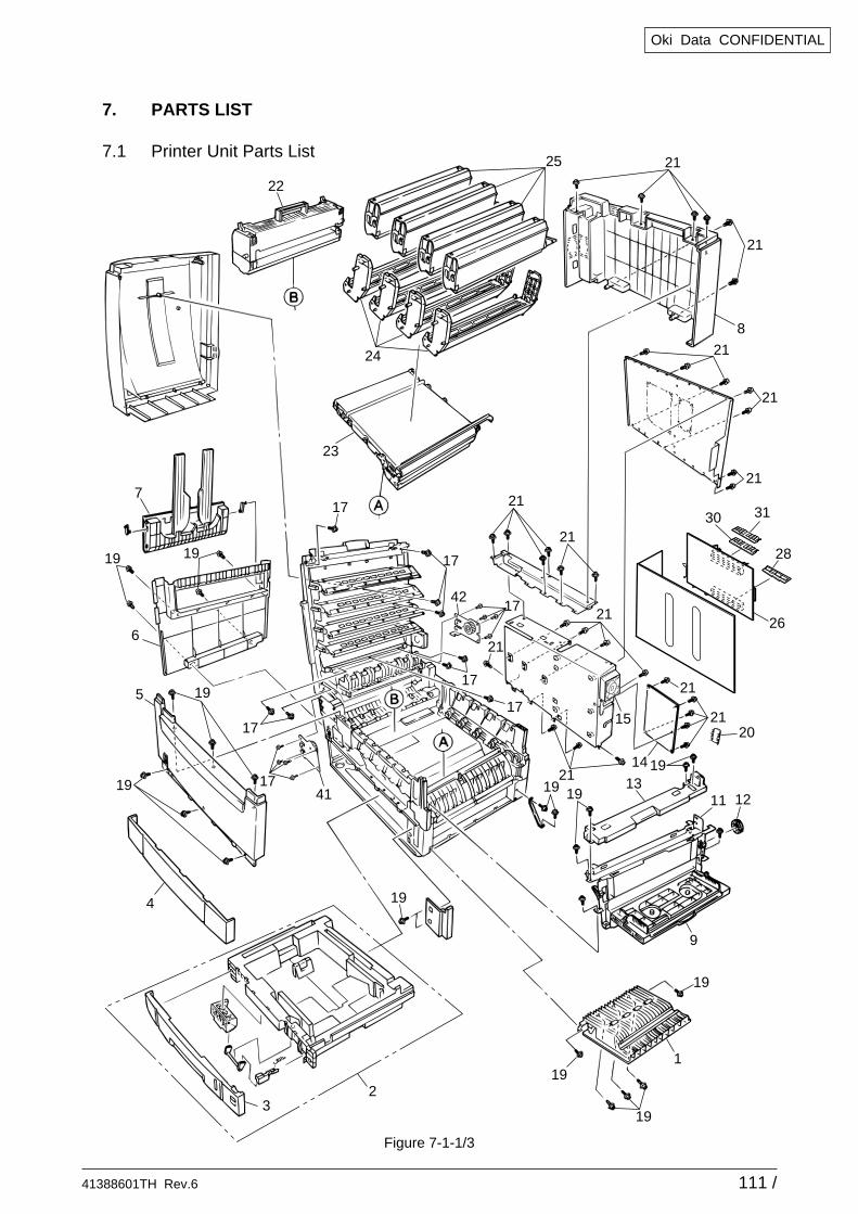
41388601TH Rev.6 111 /
Oki Data CONFIDENTIAL
Figure 7-1-1/3
5
15
21
21
21
21
21
21
21
21
26
28
30 31
21
21
42
21
21
1
2
8
20
14
1211
19
19
19
19
19
19
19
19 19
19
19 13
23
17
17
17
17
17
17
17
6
22
7
4
3
9
41
25
24
7. PARTS LIST
7.1 Printer Unit Parts List
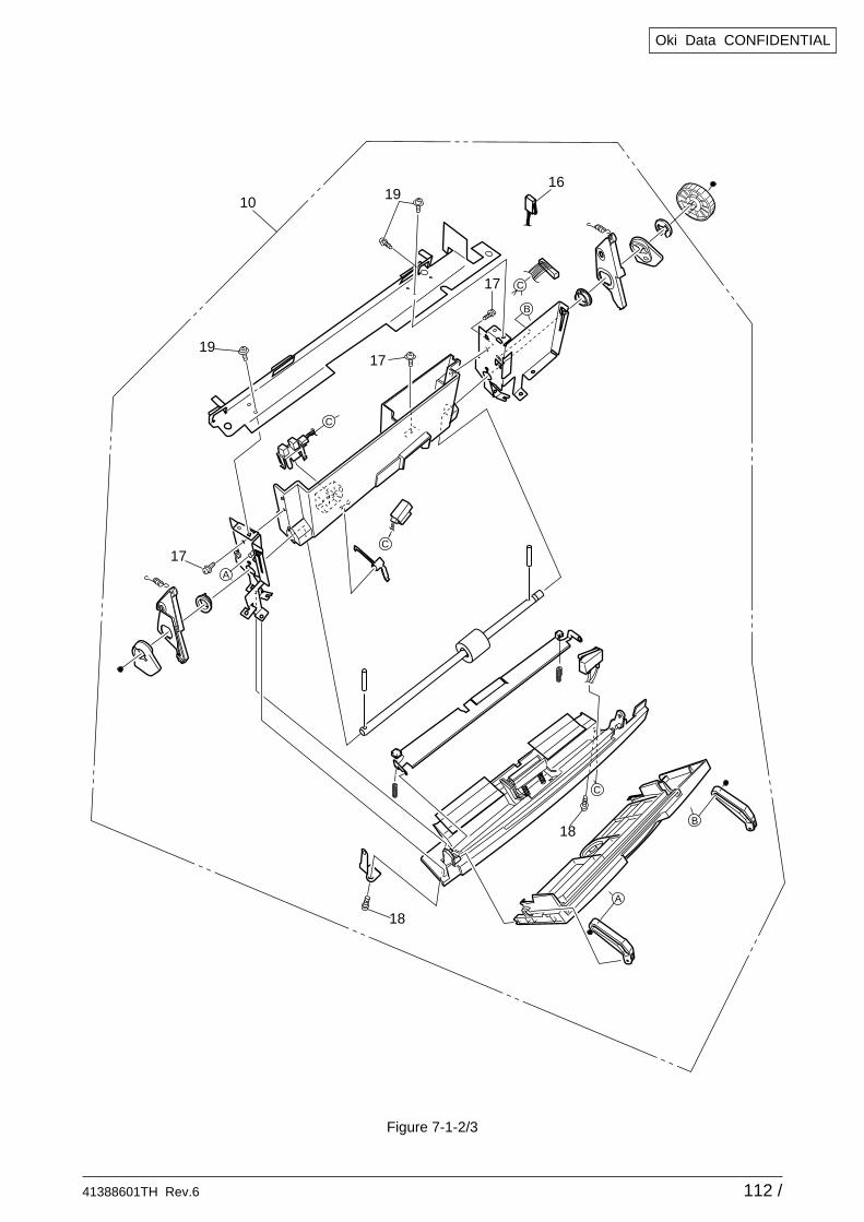
41388601TH Rev.6 112 /
Oki Data CONFIDENTIAL
A
B
A
B
C
C
C
16
19
17C
19
18
18
17
17
10
Figure 7-1-2/3
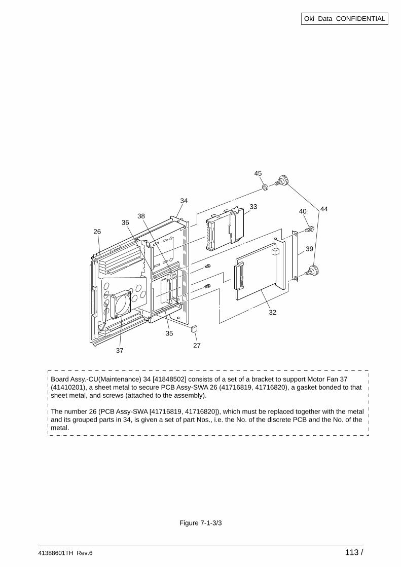
41388601TH Rev.6 113 /
Oki Data CONFIDENTIAL
38
26
3433
40 44
39
32
35
36
3727
Board Assy.-CU(Maintenance) 34 [41848502] consists of a set of a bracket to support Motor Fan 37(41410201), a sheet metal to secure PCB Assy-SWA 26 (41716819, 41716820), a gasket bonded to that sheet metal, and screws (attached to the assembly).
The number 26 (PCB Assy-SWA [41716819, 41716820]), which must be replaced together with the metal and its grouped parts in 34, is given a set of part Nos., i.e. the No. of the discrete PCB and the No. of the metal.
45
Figure 7-1-3/3
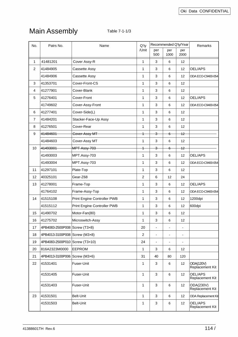
41388601TH Rev.6 114 /
Oki Data CONFIDENTIAL
No.
1
2
3
4
5
6
7
8
9
10
11
12
13
14
15
16
17
18
19
20
21
22
23
Q’ty/Unit
1
1
1
1
1
1
1
1
1
1
1
1
1
1
1
1
2
1
1
1
1
1
1
20
2
24
1
31
1
1
1
1
1
Patrs No.
41481201
41484905
41484906
41353701
41277901
41276401
41749602
41277401
41484201
41276501
41484601
41484603
41493001
41493003
41493004
41297101
40325101
41278001
41764102
41515108
41515112
41490702
41275702
4PB4083-2500P008
4PB4013-3100P008
4PB4083-2500P010
816A2323M0000
4PB4013-3100P006
41531401
41531405
41531403
41531501
41531503
Remarks
OEL/APS
ODA ECO-C9400-054
OEL/APS
ODA ECO-C9400-054
OEL/APS
ODA ECO-C9400-054
OEL/APS
ODA ECO-C9400-054
1200dpi
600dpi
ODA(120V) Replacement Kit
OEL/APS Replacement Kit
ODA(230V) Replacement Kit
ODA Replacement Kit
OEL/APS Replacement Kit
Name
Cover Assy-R
Cassette Assy
Cassette Assy
Cover-Front-CS
Cover-Blank
Cover-Front
Cover-Assy-Front
Cover-Side(L)
Stacker-Face-Up Assy
Cover-Rear
Cover-Assy MT
Cover-Assy MT
MPT Assy-703
MPT.Assy-703
MPT.Assy-703
Plate-Top
Gear-Z68
Frame-Top
Frame-Assy-Top
Print Engine Controller PWB
Print Engine Controller PWB
Motor-Fan(80)
Microswitch-Assy
Screw (T3×8)
Screw (M3×8)
Screw (T3×10)
EEPROM
Screw (M3×6)
Fuser-Unit
Fuser-Unit
Fuser-Unit
Belt-Unit
Belt-Unit
per 500
3
3
3
3
3
3
3
3
3
3
3
3
3
3
3
3
6
3
3
3
3
3
3
-
-
-
3
40
3
3
3
3
3
per 1000
6
6
6
6
6
6
6
6
6
6
6
6
6
6
6
6
12
6
6
6
6
6
6
-
-
-
6
80
6
6
6
6
6
per 2000
12
12
12
12
12
12
12
12
12
12
12
12
12
12
12
12
24
12
12
12
12
12
12
-
-
-
12
120
12
12
12
12
12
Recommended Q’ty/Year
Main Assembly Table 7-1-1/3
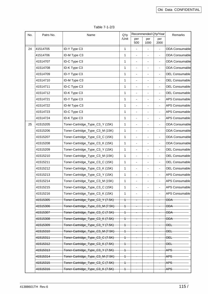
41388601TH Rev.6 115 /
Oki Data CONFIDENTIAL
No.
24
25
Q’ty/Unit
1
1
1
1
1
1
1
1
1
1
1
1
1
1
1
1
1
1
1
1
1
1
1
1
1
1
1
1
1
1
1
1
1
1
1
1
Patrs No.
41514705
41514706
41514707
41514708
41514709
41514710
41514711
41514712
41514721
41514722
41514723
41514724
41515205
41515206
41515207
41515208
41515209
41515210
41515211
41515212
41515213
41515214
41515215
41515216
41515305
41515306
41515307
41515308
41515309
41515310
41515311
41515312
41515313
41515314
41515315
41515316
Remarks
ODA Consumable
ODA Consumable
ODA Consumable
ODA Consumable
OEL Consumable
OEL Consumable
OEL Consumable
OEL Consumable
APS Consumable
APS Consumable
APS Consumable
APS Consumable
ODA Consumable
ODA Consumable
ODA Consumable
ODA Consumable
OEL Consumable
OEL Consumable
OEL Consumable
OEL Consumable
APS Consumable
APS Consumable
APS Consumable
APS Consumable
ODA
ODA
ODA
ODA
OEL
OEL
OEL
OEL
APS
APS
APS
APS
Name
ID-Y Type C3
ID-M Type C3
ID-C Type C3
ID-K Type C3
ID-Y Type C3
ID-M Type C3
ID-C Type C3
ID-K Type C3
ID-Y Type C3
ID-M Type C3
ID-C Type C3
ID-K Type C3
Toner-Cartridge_Type_C3_Y (15K)
Toner-Cartridge_Type_C3_M (15K)
Toner-Cartridge_Type_C3_C (15K)
Toner-Cartridge_Type_C3_K (15K)
Toner-Cartridge_Type_C3_Y (15K)
Toner-Cartridge_Type_C3_M (15K)
Toner-Cartridge_Type_C3_C (15K)
Toner-Cartridge_Type_C3_K (15K)
Toner-Cartridge_Type_C3_Y (15K)
Toner-Cartridge_Type_C3_M (15K)
Toner-Cartridge_Type_C3_C (15K)
Toner-Cartridge_Type_C3_K (15K)
Toner-Cartridge_Type_C3_Y (7.5K)
Toner-Cartridge_Type_C3_M (7.5K)
Toner-Cartridge_Type_C3_C (7.5K)
Toner-Cartridge_Type_C3_K (7.5K)
Toner-Cartridge_Type_C3_Y (7.5K)
Toner-Cartridge_Type_C3_M (7.5K)
Toner-Cartridge_Type_C3_C (7.5K)
Toner-Cartridge_Type_C3_K (7.5K)
Toner-Cartridge_Type_C3_Y (7.5K)
Toner-Cartridge_Type_C3_M (7.5K)
Toner-Cartridge_Type_C3_C (7.5K)
Toner-Cartridge_Type_C3_K (7.5K)
per 500
-
-
-
-
-
-
-
-
-
-
-
-
-
-
-
-
-
-
-
-
-
-
-
-
-
-
-
-
-
-
-
-
-
-
-
-
per 1000
-
-
-
-
-
-
-
-
-
-
-
-
-
-
-
-
-
-
-
-
-
-
-
-
-
-
-
-
-
-
-
-
-
-
-
-
per 2000
-
-
-
-
-
-
-
-
-
-
-
-
-
-
-
-
-
-
-
-
-
-
-
-
-
-
-
-
-
-
-
-
-
-
-
-
Recommended Q’ty/Year
Table 7-1-2/3
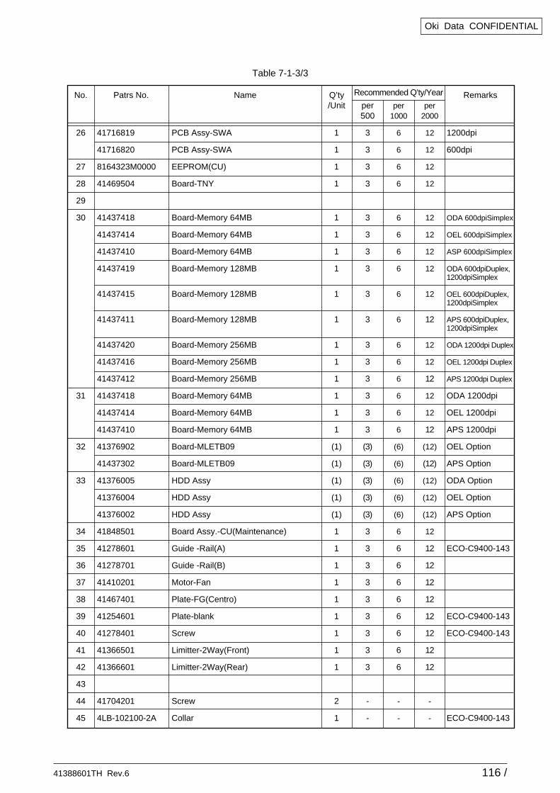
41388601TH Rev.6 116 /
Oki Data CONFIDENTIAL
Table 7-1-3/3
No.
26
27
28
29
30
31
32
33
34
35
36
37
38
39
40
41
42
43
44
45
Q’ty/Unit
1
1
1
1
1
1
1
1
1
1
1
1
1
1
1
1
(1)
(1)
(1)
(1)
(1)
1
1
1
1
1
1
1
1
1
2
1
Patrs No.
41716819
41716820
8164323M0000
41469504
41437418
41437414
41437410
41437419
41437415
41437411
41437420
41437416
41437412
41437418
41437414
41437410
41376902
41437302
41376005
41376004
41376002
41848501
41278601
41278701
41410201
41467401
41254601
41278401
41366501
41366601
41704201
4LB-102100-2A
Remarks
1200dpi
600dpi
ODA 600dpiSimplex
OEL 600dpiSimplex
ASP 600dpiSimplex
ODA 600dpiDuplex,1200dpiSimplex
OEL 600dpiDuplex,1200dpiSimplex
APS 600dpiDuplex,1200dpiSimplex
ODA 1200dpi Duplex
OEL 1200dpi Duplex
APS 1200dpi Duplex
ODA 1200dpi
OEL 1200dpi
APS 1200dpi
OEL Option
APS Option
ODA Option
OEL Option
APS Option
ECO-C9400-143
ECO-C9400-143
ECO-C9400-143
ECO-C9400-143
Name
PCB Assy-SWA
PCB Assy-SWA
EEPROM(CU)
Board-TNY
Board-Memory 64MB
Board-Memory 64MB
Board-Memory 64MB
Board-Memory 128MB
Board-Memory 128MB
Board-Memory 128MB
Board-Memory 256MB
Board-Memory 256MB
Board-Memory 256MB
Board-Memory 64MB
Board-Memory 64MB
Board-Memory 64MB
Board-MLETB09
Board-MLETB09
HDD Assy
HDD Assy
HDD Assy
Board Assy.-CU(Maintenance)
Guide -Rail(A)
Guide -Rail(B)
Motor-Fan
Plate-FG(Centro)
Plate-blank
Screw
Limitter-2Way(Front)
Limitter-2Way(Rear)
Screw
Collar
per 500
3
3
3
3
3
3
3
3
3
3
3
3
3
3
3
3
(3)
(3)
(3)
(3)
(3)
3
3
3
3
3
3
3
3
3
-
-
per 1000
6
6
6
6
6
6
6
6
6
6
6
6
6
6
6
6
(6)
(6)
(6)
(6)
(6)
6
6
6
6
6
6
6
6
6
-
-
per 2000
12
12
12
12
12
12
12
12
12
12
12
12
12
12
12
12
(12)
(12)
(12)
(12)
(12)
12
12
12
12
12
12
12
12
12
-
-
Recommended Q’ty/Year
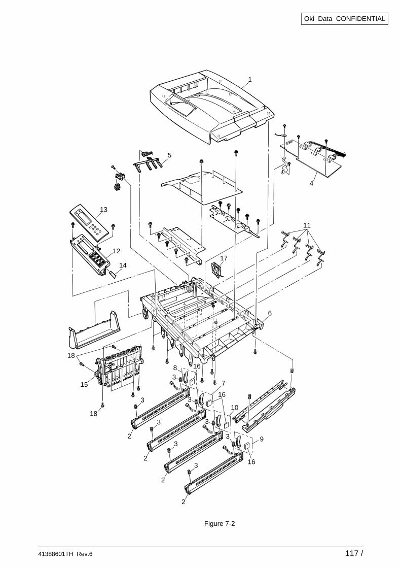
41388601TH Rev.6 117 /
Oki Data CONFIDENTIAL
Figure 7-2
16
16
16
3 9
10
7
8
3
3
3
3
3
3
3
2
2
2
2
15
18
18
14
12
13
5
1
4
11
17
6
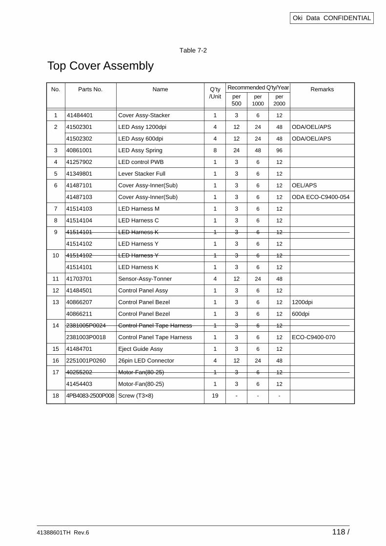
41388601TH Rev.6 118 /
Oki Data CONFIDENTIAL
No.
1
2
3
4
5
6
7
8
9
10
11
12
13
14
15
16
17
18
Q’ty/Unit
1
4
4
8
1
1
1
1
1
1
1
1
1
1
4
1
1
1
1
1
1
4
1
1
19
Parts No.
41484401
41502301
41502302
40861001
41257902
41349801
41487101
41487103
41514103
41514104
41514101
41514102
41514102
41514101
41703701
41484501
40866207
40866211
2381005P0024
2381003P0018
41484701
2251001P0260
40255202
41454403
4PB4083-2500P008
Remarks
ODA/OEL/APS
ODA/OEL/APS
OEL/APS
ODA ECO-C9400-054
1200dpi
600dpi
ECO-C9400-070
Name
Cover Assy-Stacker
LED Assy 1200dpi
LED Assy 600dpi
LED Assy Spring
LED control PWB
Lever Stacker Full
Cover Assy-Inner(Sub)
Cover Assy-Inner(Sub)
LED Harness M
LED Harness C
LED Harness K
LED Harness Y
LED Harness Y
LED Harness K
Sensor-Assy-Tonner
Control Panel Assy
Control Panel Bezel
Control Panel Bezel
Control Panel Tape Harness
Control Panel Tape Harness
Eject Guide Assy
26pin LED Connector
Motor-Fan(80-25)
Motor-Fan(80-25)
Screw (T3×8)
per 500
3
12
12
24
3
3
3
3
3
3
3
3
3
3
12
3
3
3
3
3
3
12
3
3
-
per 1000
6
24
24
48
6
6
6
6
6
6
6
6
6
6
24
6
6
6
6
6
6
24
6
6
-
per 2000
12
48
48
96
12
12
12
12
12
12
12
12
12
12
48
12
12
12
12
12
12
48
12
12
-
Recommended Q’ty/Year
Top Cover Assembly
Table 7-2
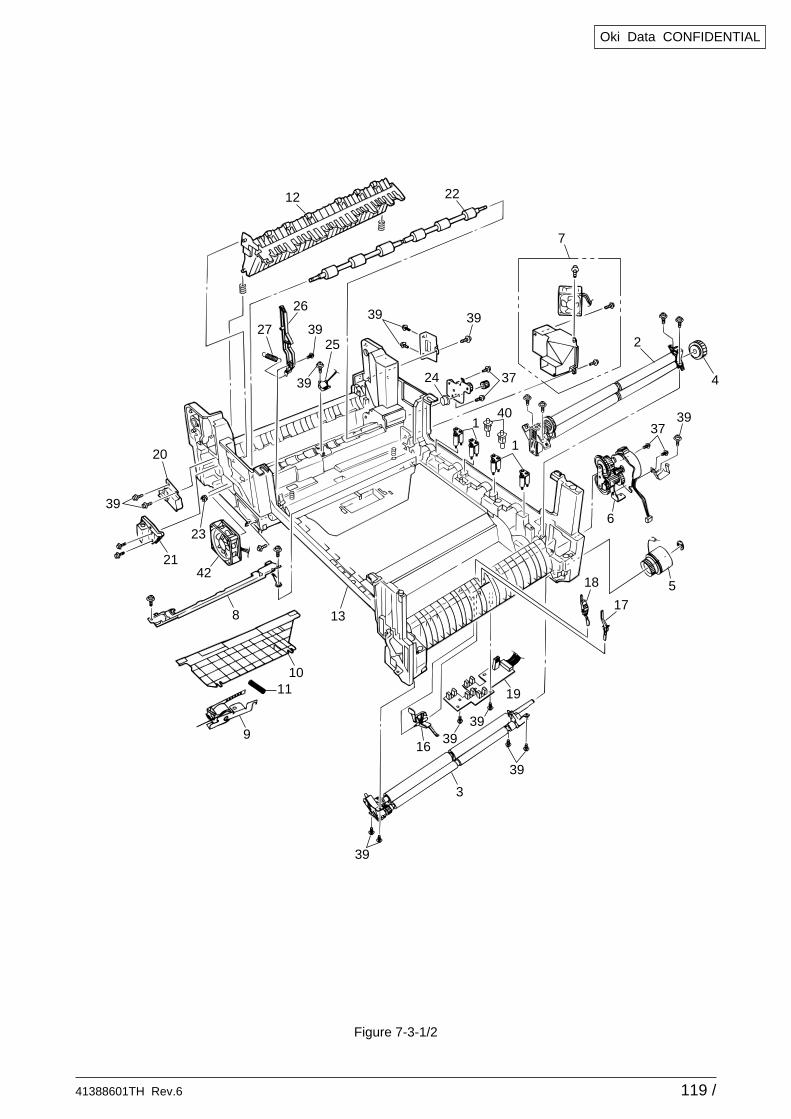
41388601TH Rev.6 119 /
Oki Data CONFIDENTIAL
Figure 7-3-1/2
12 22
39
39
3939
37
3740
1
1
2
4
6
24
39
2725
26
39
39
3939
19
3
16
11
9
39
7
518
17
10
138
4221
23
20
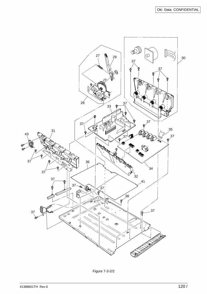
41388601TH Rev.6 120 /
Oki Data CONFIDENTIAL
37
37
37
33
37
37
37
37
37
37
2927
28
37
30
37
38
37
37
34
32
35
41
4331
37
36
Figure 7-3-2/2
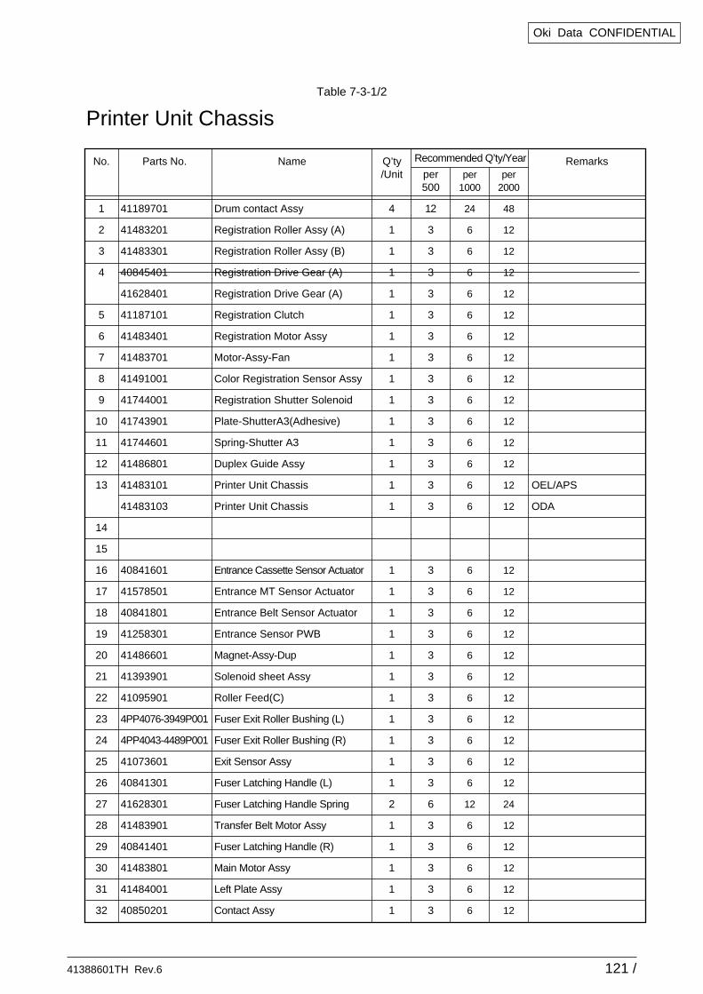
41388601TH Rev.6 121 /
Oki Data CONFIDENTIAL
No.
1
2
3
4
5
6
7
8
9
10
11
12
13
14
15
16
17
18
19
20
21
22
23
24
25
26
27
28
29
30
31
32
Q’ty/Unit
4
1
1
1
1
1
1
1
1
1
1
1
1
1
1
1
1
1
1
1
1
1
1
1
1
1
2
1
1
1
1
1
Parts No.
41189701
41483201
41483301
40845401
41628401
41187101
41483401
41483701
41491001
41744001
41743901
41744601
41486801
41483101
41483103
40841601
41578501
40841801
41258301
41486601
41393901
41095901
4PP4076-3949P001
4PP4043-4489P001
41073601
40841301
41628301
41483901
40841401
41483801
41484001
40850201
Remarks
OEL/APS
ODA
Name
Drum contact Assy
Registration Roller Assy (A)
Registration Roller Assy (B)
Registration Drive Gear (A)
Registration Drive Gear (A)
Registration Clutch
Registration Motor Assy
Motor-Assy-Fan
Color Registration Sensor Assy
Registration Shutter Solenoid
Plate-ShutterA3(Adhesive)
Spring-Shutter A3
Duplex Guide Assy
Printer Unit Chassis
Printer Unit Chassis
Entrance Cassette Sensor Actuator
Entrance MT Sensor Actuator
Entrance Belt Sensor Actuator
Entrance Sensor PWB
Magnet-Assy-Dup
Solenoid sheet Assy
Roller Feed(C)
Fuser Exit Roller Bushing (L)
Fuser Exit Roller Bushing (R)
Exit Sensor Assy
Fuser Latching Handle (L)
Fuser Latching Handle Spring
Transfer Belt Motor Assy
Fuser Latching Handle (R)
Main Motor Assy
Left Plate Assy
Contact Assy
per 500
12
3
3
3
3
3
3
3
3
3
3
3
3
3
3
3
3
3
3
3
3
3
3
3
3
3
6
3
3
3
3
3
per 1000
24
6
6
6
6
6
6
6
6
6
6
6
6
6
6
6
6
6
6
6
6
6
6
6
6
6
12
6
6
6
6
6
per 2000
48
12
12
12
12
12
12
12
12
12
12
12
12
12
12
12
12
12
12
12
12
12
12
12
12
12
24
12
12
12
12
12
Recommended Q’ty/Year
Printer Unit ChassisTable 7-3-1/2
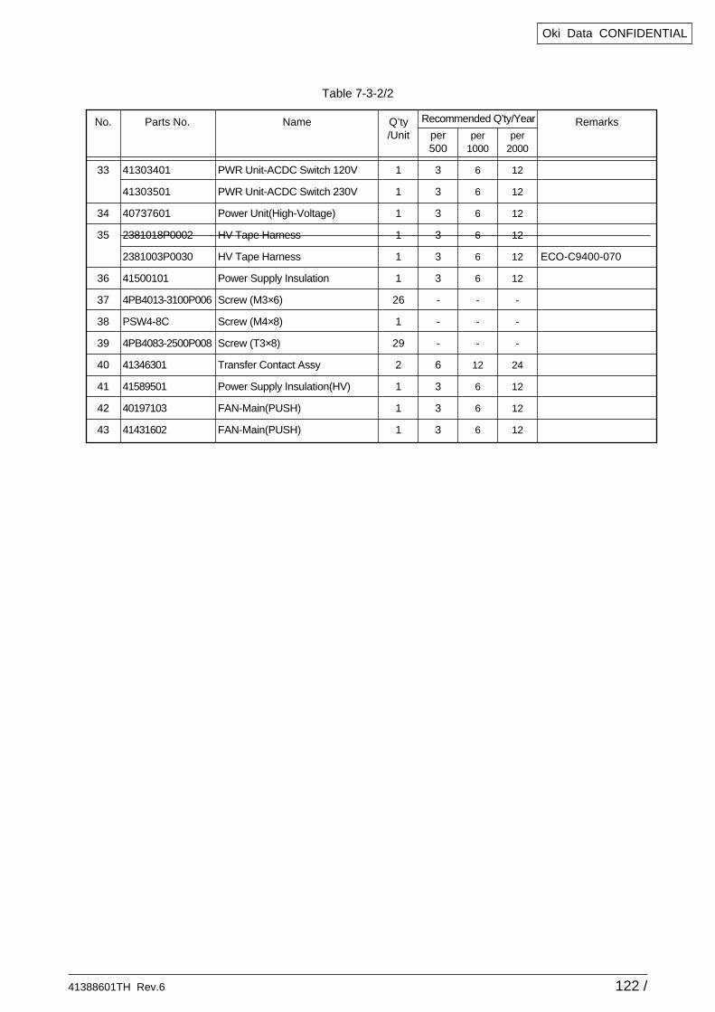
41388601TH Rev.6 122 /
Oki Data CONFIDENTIAL
No.
33
34
35
36
37
38
39
40
41
42
43
Q’ty/Unit
1
1
1
1
1
1
26
1
29
2
1
1
1
Parts No.
41303401
41303501
40737601
2381018P0002
2381003P0030
41500101
4PB4013-3100P006
PSW4-8C
4PB4083-2500P008
41346301
41589501
40197103
41431602
Remarks
ECO-C9400-070
Name
PWR Unit-ACDC Switch 120V
PWR Unit-ACDC Switch 230V
Power Unit(High-Voltage)
HV Tape Harness
HV Tape Harness
Power Supply Insulation
Screw (M3×6)
Screw (M4×8)
Screw (T3×8)
Transfer Contact Assy
Power Supply Insulation(HV)
FAN-Main(PUSH)
FAN-Main(PUSH)
per 500
3
3
3
3
3
3
-
-
-
6
3
3
3
per 1000
6
6
6
6
6
6
-
-
-
12
6
6
6
per 2000
12
12
12
12
12
12
-
-
-
24
12
12
12
Recommended Q’ty/Year
Table 7-3-2/2
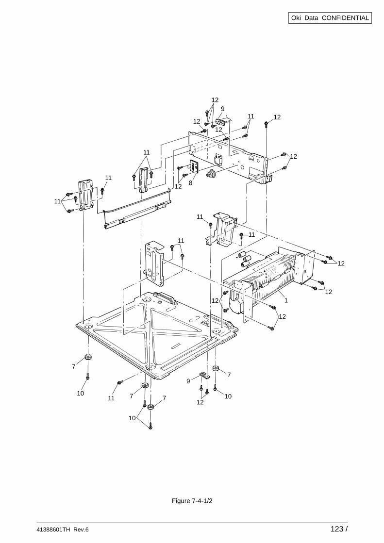
41388601TH Rev.6 123 /
Oki Data CONFIDENTIAL
912
11
11
11
11
11
11
11
11
12
12
12
12
12
12
12
12
12
12
8
1
7
10
10
10 7 7
7
9
Figure 7-4-1/2

41388601TH Rev.6 124 /
Oki Data CONFIDENTIAL
6
5
4
18
2
12
2
2
3
1312
12
12
12
12
12
13
12
17
13
16
15
12
12
Figure 7-4-2/2
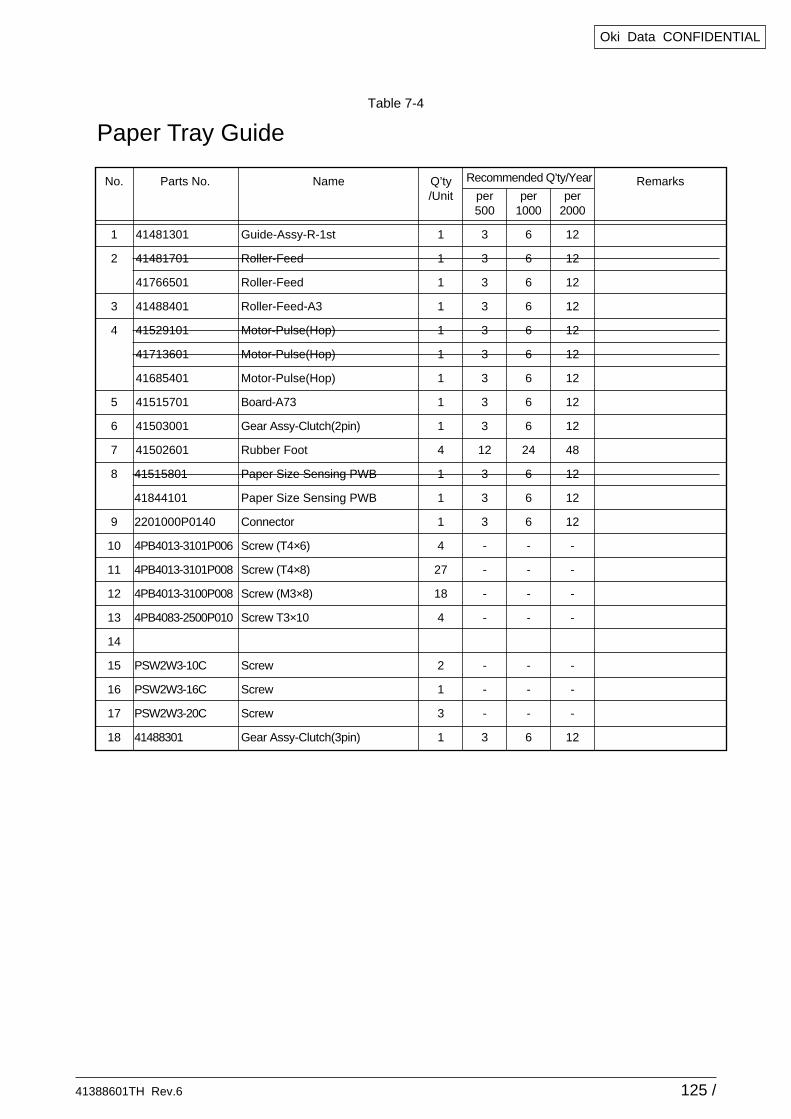
41388601TH Rev.6 125 /
Oki Data CONFIDENTIAL
No.
1
2
3
4
5
6
7
8
9
10
11
12
13
14
15
16
17
18
Q’ty/Unit
1
1
1
1
1
1
1
1
1
4
1
1
1
4
27
18
4
2
1
3
1
Parts No.
41481301
41481701
41766501
41488401
41529101
41713601
41685401
41515701
41503001
41502601
41515801
41844101
2201000P0140
4PB4013-3101P006
4PB4013-3101P008
4PB4013-3100P008
4PB4083-2500P010
PSW2W3-10C
PSW2W3-16C
PSW2W3-20C
41488301
RemarksName
Guide-Assy-R-1st
Roller-Feed
Roller-Feed
Roller-Feed-A3
Motor-Pulse(Hop)
Motor-Pulse(Hop)
Motor-Pulse(Hop)
Board-A73
Gear Assy-Clutch(2pin)
Rubber Foot
Paper Size Sensing PWB
Paper Size Sensing PWB
Connector
Screw (T4×6)
Screw (T4×8)
Screw (M3×8)
Screw T3×10
Screw
Screw
Screw
Gear Assy-Clutch(3pin)
per 500
3
3
3
3
3
3
3
3
3
12
3
3
3
-
-
-
-
-
-
-
3
per 1000
6
6
6
6
6
6
6
6
6
24
6
6
6
-
-
-
-
-
-
-
6
per 2000
12
12
12
12
12
12
12
12
12
48
12
12
12
-
-
-
-
-
-
-
12
Recommended Q’ty/Year
Paper Tray GuideTable 7-4
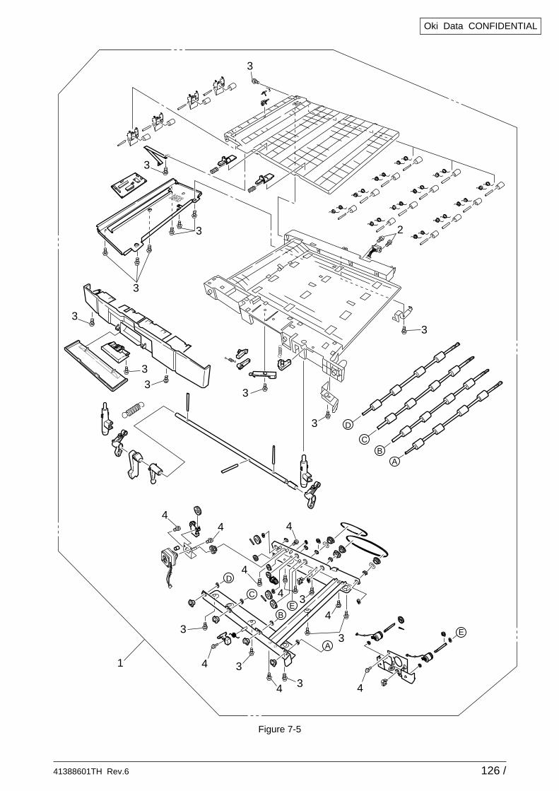
41388601TH Rev.6 126 /
Oki Data CONFIDENTIAL
AB
C
D
E
A
B
C
D
E
2
3
3
1
3
3
3
3
3
3
3
3
33
3
44
4
4
4
4
4 4
4
3
3
Figure 7-5
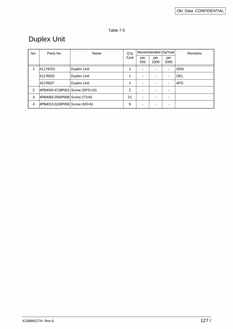
41388601TH Rev.6 127 /
Oki Data CONFIDENTIAL
Table 7-5
No.
1
2
3
4
Q’ty/Unit
1
1
1
2
21
9
Parts No.
41178201
41178203
41178207
4PB4043-4718P001
4PB4083-2500P008
4PB4013-3100P006
Remarks
ODA
OEL
APS
Name
Duplex Unit
Duplex Unit
Duplex Unit
Screw (SP3×10)
Screw (T3×8)
Screw (M3×6)
per 500
-
-
-
-
-
-
per 1000
-
-
-
-
-
-
per 2000
-
-
-
-
-
-
Recommended Q’ty/Year
Duplex Unit
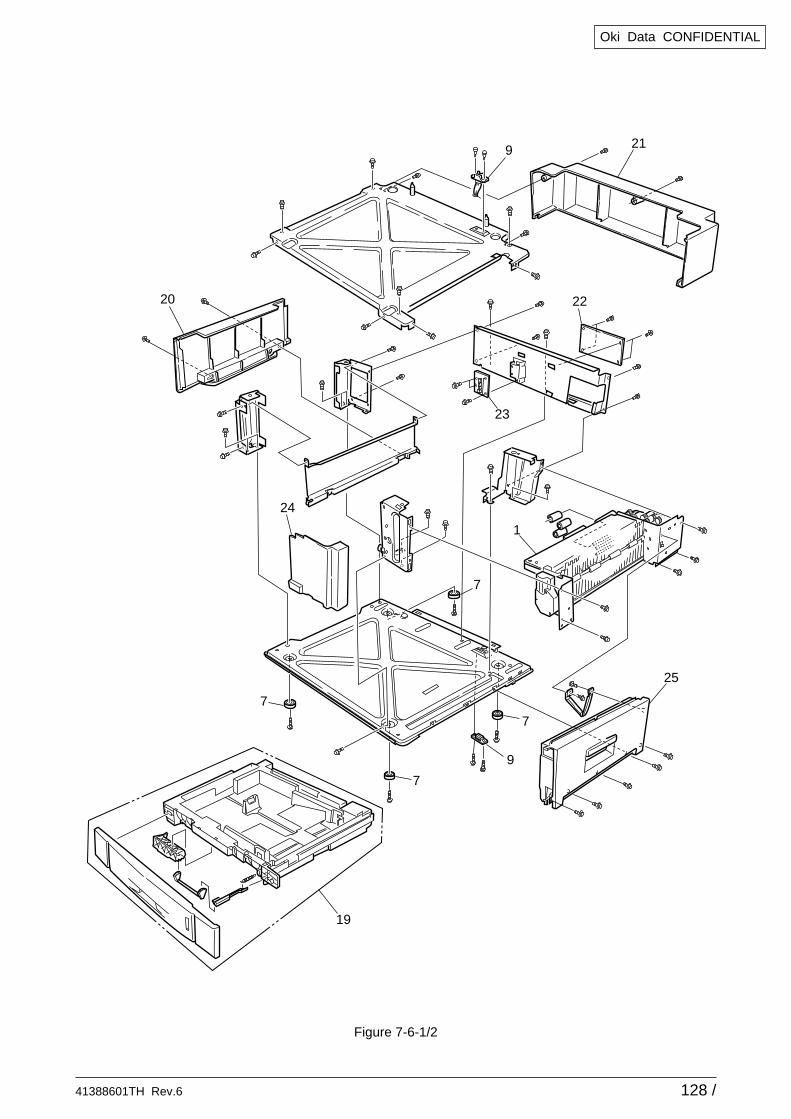
41388601TH Rev.6 128 /
Oki Data CONFIDENTIAL
20
24
25
1
7
7
7
7
9
23
22
219
19
Figure 7-6-1/2
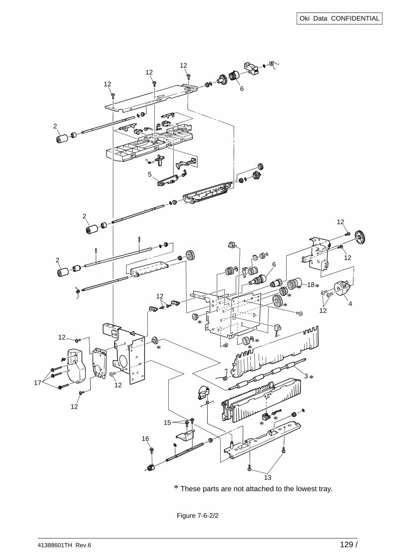
41388601TH Rev.6 129 /
Oki Data CONFIDENTIAL
Figure 7-6-2/2
4
6
3
12
12
12
12
12
12
17
13
16
15
18
12
6
5
2
12
2
2
1212
**
*
*
*
*
*
*
**
* These parts are not attached to the lowest tray.
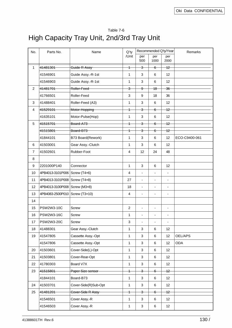
41388601TH Rev.6 130 /
Oki Data CONFIDENTIAL
No.
1
2
3
4
5
6
7
8
9
10
11
12
13
14
15
16
17
18
19
20
21
22
23
24
25
Q’ty/Unit
1
1
1
3
3
1
1
1
1
1
1
1
4
1
4
27
18
4
2
1
3
1
1
1
1
1
1
1
1
1
1
1
1
Parts No.
41481301
41546901
41546903
41481701
41766501
41488401
41529101
41635101
41515701
41515801
41844101
41503001
41502601
2201000P140
4PB4013-3101P006
4PB4013-3101P008
4PB4013-3100P008
4PB4083-2500P010
PSW2W3-10C
PSW2W3-16C
PSW2W3-20C
41488301
41547805
41547806
41503601
41503801
41780303
41515801
41844101
41503701
41481201
41546501
41546503
Remarks
ECO-C9400-061
OEL/APS
ODA
Name
Guide R Assy
Guide Assy.-R-1st
Guide Assy.-R-1st
Roller-Feed
Roller-Feed
Roller-Feed (A3)
Motor-Hopping
Motor-Pulse(Hop)
Board-A73
Board-B73
B73 Board(Rework)
Gear Assy.-Clutch
Rubber-Foot
Connector
Screw (T4×6)
Screw (T4×8)
Screw (M3×8)
Screw (T3×10)
Screw
Screw
Screw
Gear Assy.-Clutch
Cassette Assy.-Opt
Cassette Assy.-Opt
Cover-Side(L)-Opt
Cover-Rear-Opt
Board V7X
Paper Size sensor
Board-B73
Cover-Side(R)Sub-Opt
Cover-Side R Assy
Cover Assy.-R
Cover Assy.-R
per 500
3
3
3
9
9
3
3
3
3
3
3
3
12
3
-
-
-
-
-
-
-
3
3
3
3
3
3
3
3
3
3
3
3
per 1000
6
6
6
18
18
6
6
6
6
6
6
6
24
6
-
-
-
-
-
-
-
6
6
6
6
6
6
6
6
6
6
6
6
per 2000
12
12
12
36
36
12
12
12
12
12
12
12
48
12
-
-
-
-
-
-
-
12
12
12
12
12
12
12
12
12
12
12
12
Recommended Q’ty/Year
High Capacity Tray Unit, 2nd/3rd Tray UnitTable 7-6
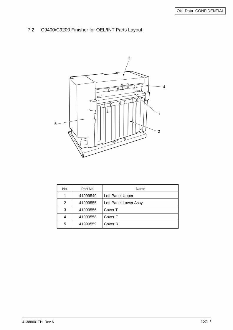
41388601TH Rev.6 131 /
Oki Data CONFIDENTIAL
7.2 C9400/C9200 Finisher for OEL/INT Parts Layout
No.
1
2
3
4
5
Part No.
41999549
41999555
41999556
41999558
41999559
Name
Left Panel Upper
Left Panel Lower Assy
Cover T
Cover F
Cover R
3
4
1
2
5
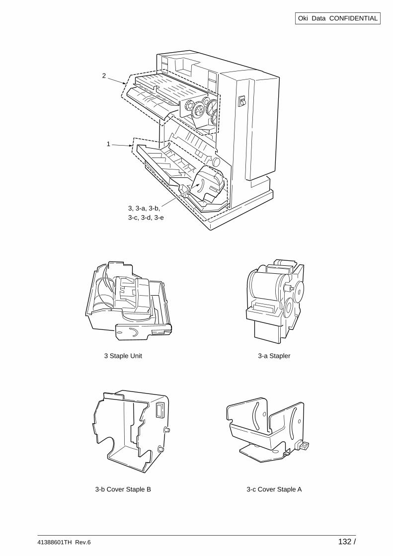
41388601TH Rev.6 132 /
Oki Data CONFIDENTIAL
1
3 Staple Unit 3-a Stapler
3-b Cover Staple B 3-c Cover Staple A
2
3, 3-a, 3-b,3-c, 3-d, 3-e
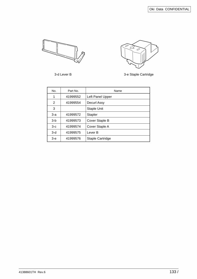
41388601TH Rev.6 133 /
Oki Data CONFIDENTIAL
No.
1
2
3
3-a
3-b
3-c
3-d
3-e
Part No.
41999552
41999554
41999572
41999573
41999574
41999575
41999576
Name
Left Panel Upper
Decurl Assy
Staple Unit
Stapler
Cover Staple B
Cover Staple A
Lever B
Staple Cartridge
3-d Lever B 3-e Staple Cartridge
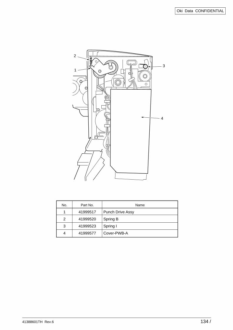
41388601TH Rev.6 134 /
Oki Data CONFIDENTIAL
No.
1
2
3
4
Part No.
41999517
41999520
41999523
41999577
Name
Punch Drive Assy
Spring B
Spring I
Cover-PWB-A
2
13
4
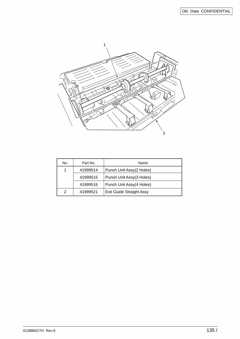
41388601TH Rev.6 135 /
Oki Data CONFIDENTIAL
No.
1
2
Part No.
41999514
41999515
41999516
41999521
Name
Punch Unit Assy(2 Holes)
Punch Unit Assy(3 Holes)
Punch Unit Assy(4 Holes)
Exit Guide Straight Assy
1
2
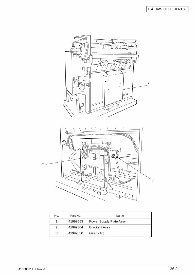
41388601TH Rev.6 136 /
Oki Data CONFIDENTIAL
No.
1
2
3
Part No.
41999553
41999504
41999530
Name
Power Supply Plate Assy
Bracket I Assy
Gear(Z16)
1
2
3
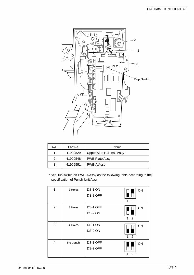
41388601TH Rev.6 137 /
Oki Data CONFIDENTIAL
No.
1
2
3
Part No.
41999529
41999548
41999551
Name
Upper Side Harness Assy
PWB Plate Assy
PWB-A Assy
1
2
3
Dup Switch
1
2
3
4
2 Holes
3 Holes
4 Holes
No punch
DS-1:ON
DS-2:OFF
DS-1:OFF
DS-2:ON
DS-1:ON
DS-2:ON
DS-1:OFF
DS-2:OFF
* Set Dup switch on PWB-A Assy as the following table according to the specification of Punch Unit Assy.
1 2
ON
1 2
ON
1 2
ON
1 2
ON
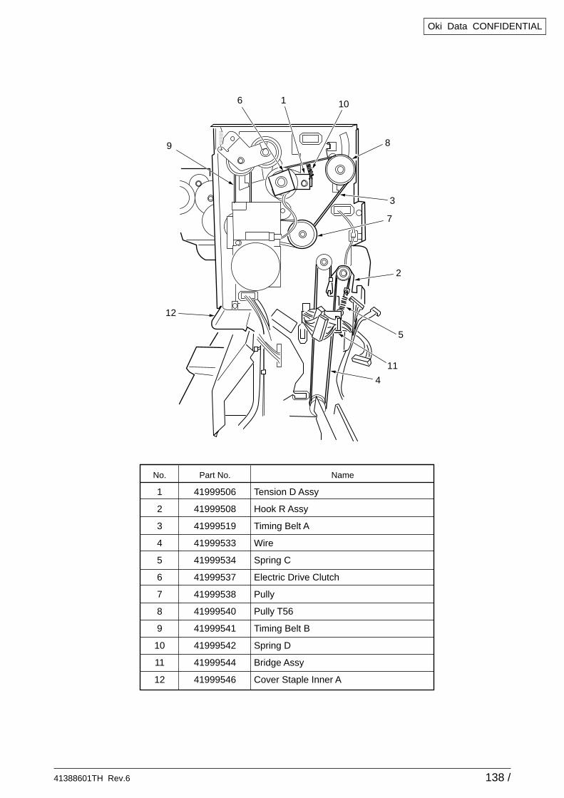
41388601TH Rev.6 138 /
Oki Data CONFIDENTIAL
No.
1
2
3
4
5
6
7
8
9
10
11
12
Part No.
41999506
41999508
41999519
41999533
41999534
41999537
41999538
41999540
41999541
41999542
41999544
41999546
Name
Tension D Assy
Hook R Assy
Timing Belt A
Wire
Spring C
Electric Drive Clutch
Pully
Pully T56
Timing Belt B
Spring D
Bridge Assy
Cover Staple Inner A
3
8
7
4
1 10
11
12
6
9
2
5
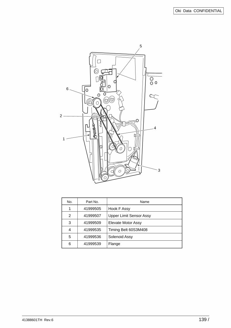
41388601TH Rev.6 139 /
Oki Data CONFIDENTIAL
No.
1
2
3
4
5
6
Part No.
41999505
41999507
41999509
41999535
41999536
41999539
Name
Hook F Assy
Upper Limit Sensor Assy
Elevate Motor Assy
Timing Belt 60S3M408
Solenoid Assy
Flange
3
4
1
6
2
5
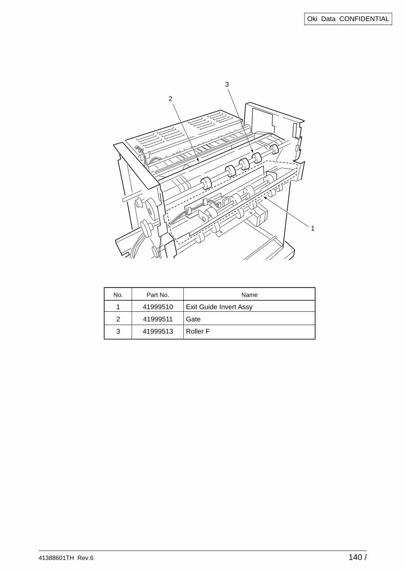
41388601TH Rev.6 140 /
Oki Data CONFIDENTIAL
No.
1
2
3
Part No.
41999510
41999511
41999513
Name
Exit Guide Invert Assy
Gate
Roller F
2
1
3
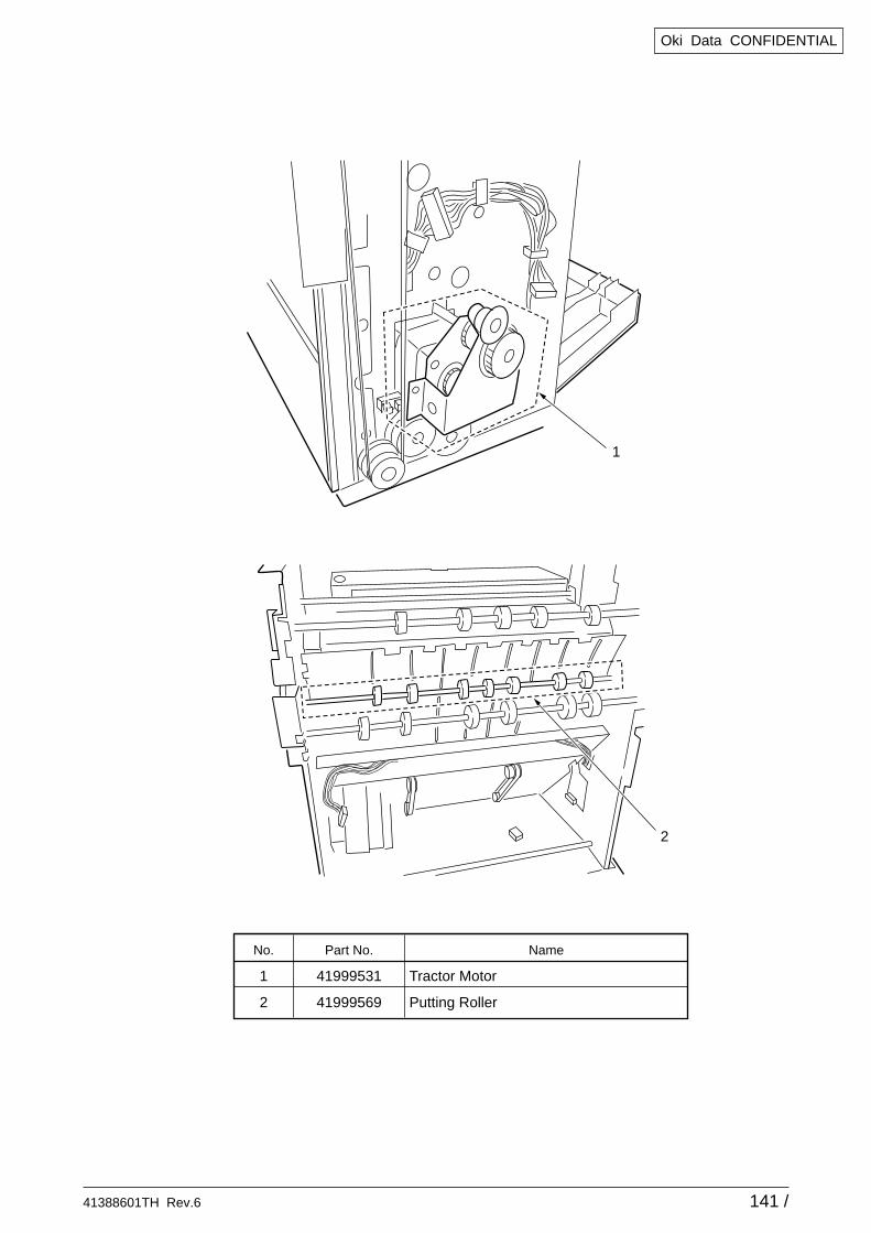
41388601TH Rev.6 141 /
Oki Data CONFIDENTIAL
No.
1
2
Part No.
41999531
41999569
Name
Tractor Motor
Putting Roller
2
1
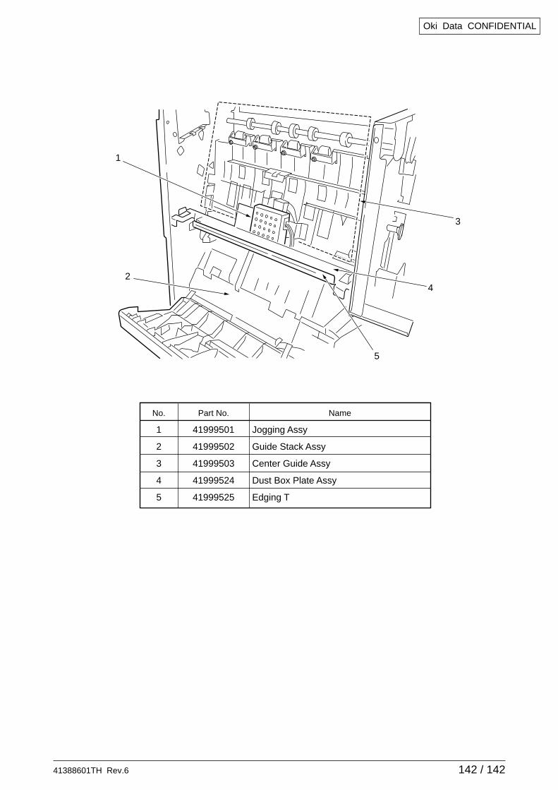
41388601TH Rev.6 142 / 142
Oki Data CONFIDENTIAL
No.
1
2
3
4
5
Part No.
41999501
41999502
41999503
41999524
41999525
Name
Jogging Assy
Guide Stack Assy
Center Guide Assy
Dust Box Plate Assy
Edging T
3
4
1
2
5