Embed Size (px)
Citation preview

UNIVERSITY OF OULU P .O. Box 8000 F I -90014 UNIVERSITY OF OULU FINLAND
A C T A U N I V E R S I T A T I S O U L U E N S I S
University Lecturer Tuomo Glumoff
University Lecturer Santeri Palviainen
Postdoctoral research fellow Sanna Taskila
Professor Olli Vuolteenaho
University Lecturer Veli-Matti Ulvinen
Planning Director Pertti Tikkanen
Professor Jari Juga
University Lecturer Anu Soikkeli
Professor Olli Vuolteenaho
Publications Editor Kirsti Nurkkala
ISBN 978-952-62-1712-3 (Paperback)ISBN 978-952-62-1713-0 (PDF)ISSN 0355-3213 (Print)ISSN 1796-2226 (Online)
U N I V E R S I TAT I S O U L U E N S I SACTAC
TECHNICA
U N I V E R S I TAT I S O U L U E N S I SACTAC
TECHNICA
OULU 2017
C 630
Jaakko Palosaari
ENERGY HARVESTINGFROM WALKING USING PIEZOELECTRIC CYMBAL AND DIAPHRAGM TYPE STRUCTURES
UNIVERSITY OF OULU GRADUATE SCHOOL;UNIVERSITY OF OULU,FACULTY OF INFORMATION TECHNOLOGY AND ELECTRICAL ENGINEERING
C 630
AC
TAJaakko Palosaari
C630etukansi.kesken.fm Page 1 Wednesday, October 18, 2017 12:08 PM


ACTA UNIVERS ITAT I S OULUENS I SC Te c h n i c a 6 3 0
JAAKKO PALOSAARI
ENERGY HARVESTING FROM WALKING USING PIEZOELECTRIC CYMBAL AND DIAPHRAGM TYPE STRUCTURES
Academic dissertation to be presented with the assent ofthe Doctoral Training Committee of Technology andNatural Sciences of the University of Oulu for publicdefence in Auditorium TS101, Linnanmaa, on 13December 2017, at 12 noon
UNIVERSITY OF OULU, OULU 2017

Copyright © 2017Acta Univ. Oul. C 630, 2017
Supervised byDocent Jari JuutiProfessor Heli Jantunen
Reviewed byProfessor Ahmad SafariProfessor Erno Keskinen
ISBN 978-952-62-1712-3 (Paperback)ISBN 978-952-62-1713-0 (PDF)
ISSN 0355-3213 (Printed)ISSN 1796-2226 (Online)
Cover DesignRaimo Ahonen
JUVENES PRINTTAMPERE 2017
OpponentsProfessor Ahmad SafariProfessor Tim Button

Palosaari, Jaakko, Energy harvesting from walking using piezoelectric cymbal anddiaphragm type structures. University of Oulu Graduate School; University of Oulu, Faculty of Information Technologyand Electrical EngineeringActa Univ. Oul. C 630, 2017University of Oulu, P.O. Box 8000, FI-90014 University of Oulu, Finland
Abstract
Many electrical devices already surround us in our everyday life. Some devices monitor carperformance and traffic while others exist in handheld devices used by the general public.Electrical devices also control manufacturing processes and protect workers from exposure tohazardous working environment. All these devices require electricity to operate. This exponentialgrowth of low power electronic devices in industry, healthcare, military, transportation and inportable personal devices has led to an urgent need for system integrated energy sources.
Many energy harvesting technologies have been developed to serve as a power source in closeproximity to the electrical device itself. Solar and magnetic energy harvesters are the mostcommon solutions when conditions are suitable. A more recent technique, called piezoelectricenergy harvesting, has raised significant interest among scientists and in industry. Throughpiezoelectric (ceramic) material mechanical energy can be harvested and converted to electricalenergy. This method requires accurate analysis of the kinetic energy experienced by thepiezoelectric material so that the mechanics can be suitably designed. At the same time themechanical design has to protect the piezoelectric material from intense forces that might causecracks, while still transmitting the kinetic energy efficiently. These requirements usually mean aspecific energy harvest design for each ambient energy source at hand.
This thesis is focused on energy harvesting from low frequency compressions usingpiezoelectric ceramic materials. The objective was to manufacture, measure and implementstructures that could sustain the forces experienced under the heel of a foot and maximize theharvested energy amount and efficiency. Two different construction designs were developed andoptimised with an iterative process. The kinetic energy impulse under the heel part of the foot wasstudied by measuring the electrical output of the harvester during walking and then analysed withmodelling software. The results were used to create a walking profile for a computer controlledpiston to study the input energy phase, speed and force influence on the amount of the harvestedenergy and the efficiency of the harvesting process. Finally, the functionality of the concept wastested in a real environment with an energy harvester inserted inside a running shoe. Thedeveloped harvester showed the highest energy density reported in this frequency region.
Keywords: bimorph, cymbal, energy harvest, piezoelectric, pre-stressed, unimorph


Palosaari, Jaakko, Pietsosähköinen energiankeräys kävelystä cymbal ja kalvo-typpisillä rakenteilla. Oulun yliopiston tutkijakoulu; Oulun yliopisto, Tieto- ja sähkötekniikan tiedekuntaActa Univ. Oul. C 630, 2017Oulun yliopisto, PL 8000, 90014 Oulun yliopisto
Tiivistelmä
Monet elektroniset laitteet ympäröivät meitä jokapäiväisessä elämässä. Ne tarkkailevat autontoimintaa tai liikennettä ja toiset toimivat aina mukana kulkevissa kannettavissa laitteissa. Töissäne valvovat valmistusprosesseja tai varoittavat työntekijöitä vaarallisista työolosuhteista. Kaikkinämä laitteet tarvitsevat sähköä toimiakseen. Pienitehoisten elektronisten laitteiden eksponenti-aalinen kasvu teollisuudessa, terveyssektorilla, puolustusteollisuudessa, kulkuneuvoissa sekäkannettavassa kulutuselektroniikassa on johtanut suureen tarpeeseen kehittää järjestelmiin integ-roituja energialähteitä.
Monia energiankeräystekniikoita on kehitetty toimimaan elektronisten laitteiden läheisyydes-sä. Aurinkopaneelit ja magneettiset energiankeräysmenetelmät ovat yleisimpiä ratkaisuja, josolosuhteet antavat siihen mahdollisuuden. Pietsosähköinen energiankeräys on uudempi tekniik-ka, joka on herättänyt kasvavaa huomiota tutkimusyhteisössä sekä teollisuudessa. Pietsosähköi-sen materiaalin avulla mekaaninen energia voidaan muuntaa suoraan sähköiseksi energiaksi.Tässä tekniikassa kineettinen energia tulee analysoida tarkasti mekaniikka suunnittelua varten,jotta se saadaan kohdistettua tehokkaasti pietsosähköiseen materiaaliin. Lisäksi mekaniikan tuleesuojata materiaalia voimilta, jotka voivat johtaa murtumiin. Näistä vaatimuksista johtuen jokai-nen ulkoinen energialähde vaatii yleensä yksilöllisen energiankeräysrakenteen.
Tämä väitöstyö keskittyy pietsosähköisten keraamien hyödyntämiseen energiankeräyksessämatalataajuisista mekaanisista voimista. Tarkoituksena oli suunnitella, valmistaa, mitata ja asen-taa rakenteita, jotka kestävät kantapäähän kohdistuvia voimia kävelyn ja juoksun aikana sekämaksimoida talteen saatava energia ja hyötysuhde. Kaksi erilaista rakennetta suunniteltiin, val-mistettiin ja optimoitiin energiankeräystä varten. Kantapäähän kohdistuva kineettinen energiaanalysoitiin mallinnusohjelmistolla ja mittaamalla sähköinen vaste energiakeräys rakenteesta.Tuloksien avulla suunniteltiin kävelyprofiilia imitoiva mekaaninen männän liike, jonka avullatutkittiin kohdistettavan voiman nopeuden, vaiheen ja suuruuden vaikutusta energiankeräyksenhyötysuhteeseen ja saatavaan tehoon. Viimeisenä energiankeräysrakenteen toimivuutta testattiinoikeassa ympäristössä asentamalla se juoksukenkään. Kehitetyllä pietsosähköisellä energiakeräi-mellä saavutettiin korkeimmat raportoidut energiatiheydet käytetyllä taajuusalueella.
Asiasanat: bimorph, cymbal, energiankeräys, esijännitys, pietsosähköinen, unimorph


7
Acknowledgements
I wish to express my sincere gratitude to my supervisors Docent Jari Juuti and
Professor Heli Jantunen for granting me the opportunity to work in the
Microelectronics laboratory. I am truly grateful for having their trust, support and
encouragement to proceed with research in the field of my greatest interest and to
complete this work. I would also like to thank my colleagues for their altruistic help
and a laid-back working atmosphere. Special acknowledgement goes to Dr. Mikko
Leinonen for his tremendous help in the designing, measuring and understanding
of the physics behind the work. Huge thanks go to Pekka Moilanen whose guidance
and attention to the finest details has also been a key element to my scientific
accomplishments throughout my entire research. An extra strong hand-shake must
also be given to Antti Paavola for helping to set up the “amberla” environments, for
numerous mechanical installations and for manufacturing advice.
This work has been financially supported by the Jenny and Antti Wihuri foundation,
the Finnish Foundation for Technology Promotion and the Tauno Tönningin
foundation.
Oulu, December 2017 Jaakko Palosaari

8

9
List of abbreviations and symbols
AC Alternating current
AFM Atomic force microscope
DSSH Double Synchronized Switch Harvesting
FEM Finite element method C Capacitance
d31 Piezoelectric coefficient
d33 Piezoelectric coefficient
DC Direct current
Eeff Harvested energy efficiency
Ein Compression energy
Eout Harvested energy
Fp Piston force
Fs Pre-stress force
k31 Coupling factor
k33 Coupling factor
MEMS Microelectromechanical system
P Power
PC Polycarbonate POM Polyoxymethylene
PSI-5A4E Lead zirconate titane type 5A PVDF Polyvinylidenefluoride
PZ-5A Lead zirconate titanate type 5A
PZT-5H Lead zirconate titanate type 5H
PZT Lead zirconate titanate
Q Mechanical quality factor
R Electrical load resistance
R1 Piezoelectric disc radius
R2 Clamping inner radius
R3 Clamping outer radius
RL Electrical load resistance
SECE Synchronous Electric Charge Extraction
SSHI Synchronized Switch Harvesting on Inductor
tp Piezoelectric disc thickness
ts Steel thickness

10
U Voltage
x1 Compression starting point
x2 Compression ending point
x Compression distance
ZnO Zinc oxide

11
List of original publications
This thesis is based on the following publications, which are referred to throughout
the text by their Roman numerals:
I Palosaari J, Leinonen M, Hannu J, Juuti J & Jantunen H (2012) Energy harvesting with a cymbal type piezoelectric transducer from low frequency compression. Journal of Electroceramics, 28(4):214-219
II Leinonen M, Palosaari J, Juuti J & Jantunen H (2014) Combined electrical and electromechanical simulations of a piezoelectric cymbal harvester for energy harvesting from walking. Journal of Intelligent Material Systems and Structures, 25(4): 391-400
III Palosaari J, Leinonen M, Juuti J, Hannu J & Jantunen H (2014) Piezoelectric circular diaphragm with mechanically induced pre-stress for energy harvesting. Smart Materials and Structures, 23(8):085025
IV Palosaari J, Leinonen M, Juuti J, & Jantunen H (2016) Energy harvesting with a bimorph type piezoelectric diaphragm multilayer structure and mechanically induced pre-stress, Energy Technology, 4(5):620-624
In Paper I a cymbal type transducer structure was introduced and manufactured.
The thickness of the metal end caps was optimized with an iterative process for
energy harvesting and the piezoelectric energy harvester was measured with
different compression frequencies and forces. Paper II showed the cymbal type
energy harvester measured with sinusoidal compression cycles and compared to a
developed compression profile imitating actual walking. Compression profiles were
also analysed with a simulation model. In Paper III a diaphragm type energy
harvester was designed and manufactured. The transducer was measured under
different pre-stressing conditions to optimise the energy harvesting efficiency
related to mechanical input energy versus harvested raw electrical output energy.
In Paper IV a pre-stressed multilayer diaphragm structure was designed and
manufactured. Harvester functionality and raw output power at different speeds
were measured inside a shoe heel. The maximum output of the piezoelectric energy
harvester was measured with the developed walking profile compressions.
In Paper I, the idea was developed together with co-authors. The design,
manufacturing of the cymbal structures and measurements were done by the author.
Also the main part of the writing was done by the author. The manufacturing and
measurements for Paper II, and related writing in the range of context were done
by the author. In Paper III, the manufacturing, measuring, the idea of the adjustable
pre-stress and the main part of the writing were done by the author. In Paper IV the
idea of the concept, design, manufacturing, measuring, and the main part of the
writing were done by the author.

12

13
Contents
Abstract
Tiivistelmä
Acknowledgements 7 List of abbreviations and symbols 9 List of original publications 11 Contents 13 1 Introduction 15
1.1 Piezoelectricity ........................................................................................ 16 1.2 Piezoelectric energy harvesting ............................................................... 17 1.3 Scope and outline of the thesis ................................................................ 21
2 Cymbal type energy harvester 23 2.1 Cymbal type piezoelectric transducers .................................................... 23 2.2 Cymbal energy harvester design ............................................................. 23 2.3 Kinetic energy harvester measurement setup .......................................... 25 2.4 Structural optimisation of cymbal type energy harvester ........................ 26
3 Diaphragm type energy harvester 37 3.1 Diaphragm type transducers .................................................................... 37 3.2 Unimorph diaphragm energy harvester design ....................................... 38 3.3 Results of the unimorph type energy harvester ....................................... 41 3.4 Multilayer bimorph energy harvester design ........................................... 48 3.5 Measurement results of the multilayer bimorph type harvester .............. 50
4 Conclusions 57 List of references 61 Original publications 69

14

15
1 Introduction
Energy harvesting is a process where ambient energy in different forms is converted
to another form of energy and potentially stored for future use. As there are many
types of energy that can be harvested there are also many different harvesting
techniques. The most common and well known are solar, biomass and magnetic
energy harvesting. In solar energy harvested light is converted by photocells to
electricity. From biomass such as trees and plants, energy can be directly converted
through combustion to heat or, after being processed to biofuel, via a fuel cell to
electricity, although this can be considered as energy production. Magnetic energy
harvesters are used to convert mechanical energy directly to electrical energy. This
method is also usually related to energy production but is also used in energy
harvesting in many publications. Piezoelectric energy harvesting is not so familiar
to the general public. As with the magnetic harvesters, piezoelectric materials can
also convert mechanical energy to electricity and vice versa. Mechanical energy
strain inside the piezoelectric material is released as an electrical charge, which can
be harvested or used as a measurement signal. Due to this reversible
electromechanical interaction, piezoelectric materials have been used for decades in
many applications as actuators, sensors and ultrasonic motors.
Recently piezoelectric energy harvesting has raised a great deal of interest as
the quantity of portable electronics has sky rocketed. Due to the developments of
signal processing with low power consumption and the growing demand for a small
scale energy source for self-sufficient sensor systems, piezoelectric energy
harvesting has become a viable potential candidate. For example measuring,
controlling and predicting possible maintenance during manufacturing with
portable, self-sufficient and cost efficient solutions is now seen as a real possibility.
Energy harvesting from human motion is very attractive as we carry many portable
devices with us and a continuous source of power would open possibilities for
further wearable electronics. For example the healthcare industry would be
interested in self-supporting sensors that could monitor a patient’s heart rate, blood
pressure, blood sugar levels or oxygen saturation. Fig. 1 shows the exponential
growth in publications related to piezoelectric energy harvesters within the last 16
years.

16
Fig. 1. Number of publications with the keywords “piezoelectric” and “harvest” as a
function of time according to Google Scholar web site. (Collected 1.3.2017)
As future sensor systems come to be designed smaller and smaller it would be
convenient if the power source could also be scaled down. Piezoelectric energy
harvesting provides this possibility with the most miniaturized size in the regime of
microelectromechanical systems (MEMS). Another advantage is the long life span
as the piezoelectric ceramics can be manufactured to operate over wide temperature
ranges and designed to endure demanding dynamic conditions for several years.
However, the piezoelectric energy harvester demands precise mechanical and
electromechanical designs to match the ambient environment where the energy is
being harvested, robust construction for a long life span and accurate designs to
meet the energy requirements set by the application.
1.1 Piezoelectricity
Certain materials have the ability to generate an electric charge in response to
applied mechanical stress, and the related phenomenon is called the piezoelectric
effect. It was first discovered in crystals of topaz, tourmaline and quartz by the
brothers Pierre and Jacques Curie in 1880. The word piezoelectric is derived from
the Greek word piezein which means to press or squeeze. One unique feature of the
piezoelectric effect is its reversibility. Subjecting piezoelectric material to an
electric field generates expansion or shrinkage of dimensions of the material

17
meaning that it can both create stress and strain under an electric field and under
stress it can generate electricity. [1]
After the discovery of piezoelectricity, the phenomenon remained just a
laboratory experiment until World War I. The first practical application was sonar
that was used to detect submarines via ultrasonic sounds. This application inspired
a lot of interest in piezoelectric material properties and other possible applications.
A vast amount of research lead to the finding of man-made materials called
ferroelectrics which exhibited many times greater piezoelectric coefficients than
natural piezoelectric materials. Ferroelectrics are a subgroup of piezoelectric
materials, where so-called domains have a net polarization. These domains can be
orientated with an electric field enhancing the piezoelectric properties. Additionally
they offer the possibility of tailoring their performance to specific responses and
applications by the introduction of intentional impurities or “dopants” into the
material. After World War II material tailoring for specific applications and
integration directly onto circuit board was made possible and resulted in a wide
range of applications such as transducers, buzzers, igniters and signal filters for
television and radio to respond to the demands of the growing communication
industry. [2]
In the last three decades piezoelectric applications have spread into almost all
industries. For example high frequency positioning of AFM (atomic force
microscope) probes developed for research purpose and surgical instruments,
imaging and dental cleaners for medical instruments, also ultrasonic applications for
welding, level measurements, flow meters and for manufacturing and quality
inspection. Specific structures have been made for inkjet printers, vibration
damping, interferometers and optical instruments. Applications using piezoelectric
energy harvesters are still few in commercial use. Some energy harvesting
electronics and vibration based harvesters are commercially available but
integration to the final application is left to the customer. Commercial energy
harvesters usually work within a certain frequency range near to the resonance
frequency. In this case the customer has to consider overall suitability to the
environment, the electrical connections, the mounting to the ambient energy source
and whether there are sufficient vibrations to power the system. [2–7]
1.2 Piezoelectric energy harvesting
Piezoelectric energy harvesters are based on the same principle as piezoelectric
sensors which transform kinetic energy into electrical energy. In the sensor case a

18
strong and noiseless electrical signal is the design goal but in harvesters the maximal
efficiency and the amount of harvested energy are usually prioritised. To facilitate
the comparison between different energy harvesting devices, authors frequently
report the average power or raw power of the energy harvester. This is calculated
from the voltage measured across an electrical load. First publications on energy
harvesting with piezoelectric materials are from the 1980’s. In Häsler et al. (1984)
an experiment with PVDF (polyvinylideneflouride) film was implemented. PVDF is
a ferroelectric polymer and can be polarized in the same way as ferroelectric ceramics
using an electric field and, in some cases, applied tension. In the experiment a
miniaturized prototype was attached to a dog’s ribs where spontaneous breathing
expanded the PVDF film [8]. The goal was to prove a concept that enough energy could
be harvested from the human respiratory system to power implants that require a
permanent power source. Only 17 µW was achieved but the article stated that this could
be vastly improved by material research and mechanical modifications. The human
body has been used as a kinetic energy source for many energy harvesting studies.
Kymisis et al. (1998) performed measurements on 8-layer stacks of 28 µm PVDF sheets
and a PZT (lead zirconate titanate) “Thunder sensor/actuator” element embedded in a
shoe insole. The PVDF multilayer sheet provided 1.1 mW and the pre-stressed PZT
unimorph structure 1.8 mW. The prototype was able to power a RFID transmitter which
sent a signal between every 3-6 steps [9]. Another source of wasted energy was
exploited by Taylor et al. who designed strips made from PVDF to harvest energy from
river or ocean currents [10]. The concept of the idea was to store the harvested energy
in batteries so it could later to be used by sensors or robots. An energy harvesting “Eel”
was tested inside a tank with different flow speeds. The publication investigated flow
speed correlations to power output and dominant frequencies. Many studies have been
made to exploit the mechanical resonance of a piezoelectric cantilever beam or
diaphragm to harvest energy from vibrations [11–14]. For example in 2012 Wang et al. used an array of four piezoelectric circular diaphragms to harvest energy from
mechanical vibrations. The diaphragms’ resonances were tuned close to 150 Hz with
equal masses glued on top of them. Parallel electrical connection of the diaphragms
resulted in a maximal raw power output of 28 mW at resonance [14]. Another source
of energy that has been studied for piezoelectric energy harvesting is pressure
fluctuations [15–17]. These experiments usually utilized the same type of piezoelectric
circular diaphragm as utilized for vibration harvesting. The diaphragms were mounted
from the circumference and deformed as a result of pressure fluctuations. These types
of pressure harvester have been proposed to be used for example in the operation of
biomedical implants, industrial manufacturing processes, sensors and in the wireless

19
communication devices carried by scuba divers. Piezoelectric energy harvesters can be
quite easily scaled down even into microelectromechanical systems (MEMS). Liu et al. introduced a MEMS power generator that could harvest energy from low-level ambient
vibration sources. The structure consisted of an array of piezoelectric cantilevers whose
resonance frequencies were tuned by altering their dimensions and by adding different
masses at the tip of the cantilevers. A total of 16 cantilevers were fabricated inside an
area of 10 mm2 which produced 3.98 µW with a 3.93 Vdc output at a frequency of 229
Hz [18].
Because so many portable electronics are now carried with us and because all of
these devices require a battery to operate, energy harvesting from the human body has
become an attractive topic. Many investigations have been made to transform human
body heat into electricity [19–21]. Thermoelectric generator performance is strongly
dependent on ambient temperature as the efficiency is determined by the temperature
difference between thermocouples. Thermoelectric harvesters can generate power
levels in the microwatts range from an area of 1 cm2. The design challenge is to
implement one side of the thermocouples to be in contact or close to the human skin at
all times and still be open to outside temperatures on the other side while maintaining
user comfort. Energy generation from clothing has been investigated by combining
solar and thermal energy harvesting. Solar energy harvesters can generate around 3-
130 µW/cm2 from indoor solar light and from 1-100 mW/cm2 from outdoor solar light.
The solar energy harvesters are dependent on availability of the light but the incident
angle and intensity of the light source are crucial [22, 23]. Implemented solar harvesters
on clothes would rarely be at the desired optimal angle to the light source.
A lot of wasted energy is available when walking and some of this energy could
be transformed into electrical energy without causing any additional burden or wearing
any uncomfortable accessories. However, the level of harvested energy depends largely
upon mechanics and placement on the human body. Without careful designing and
knowledge of human physiology these devices could possibly cause injuries in the long
run. [24]
Piezoelectric energy harvester studies have also used human motion to
demonstrate the feasibility and functionality of the harvester. A very attractive position
for the energy harvester is inside the shoe because it absorbs most energy while
walking. The article mentioned on the previous page was by Kymisis et al. (1998) who
inserted the harvester inside a shoe insole. Shenck et al. (2001) continued this work and
enhanced the power output to 8.4 mW by implementing a double bimorph structure
instead of the single unimorph structure. Measured power from the “Thunder
sensor/actuator” element corresponded to 4.4 mW/cm3 for the active material. [25] In

20
order to enable comparison between different energy harvester schemes a
commonly used method is to calculate the generated power related to the volume
of active material. In real applications, however, the total size of the component is
also an important factor. Feenstra et al. implemented a harvester into a backpack strap
buckle which had a piezoelectric stack compressed via a mechanical amplifier. This
application delivered an average power of ~0.4 mW and was totally invisible to the
wearer which is important when designing an energy harvester having human motion
as an energy source. Another interesting demonstration has been made by Platt et al.
(2005) inside a prosthetic knee implant where a piezoelectric stack was used to harvest
enough energy to power sensors that could potentially provide in vivo diagnostics for
the whole 20 years lifetime of the implant. Such sensors could detect abnormal
misalignments, loosening or premature detection of wear and so minimize harm to the
patient. [9, 25–31].
Regardless of the source of harvested energy, from wind, ocean, ambient
vibrations, pressure deviations or kinetic energy, all piezoelectric energy harvesters rely
on compressing and/or tensioning of the piezoelectric material. Harvesters that focus
on applying stress to the material along the polarization axis generate the electric field
or charge through the piezoelectric coefficient d33 which is based on material properties.
A good example of a harvester that utilizes compression of piezoelectric material is by
Feenstra et al. where a mechanical amplifier was used to amplify the applied forces and
generate electrical energy from a piezoelectric stack [32]. Piezoelectric coefficient d33,
through which the electric field is obtained when strain is orthogonal to the polarization
axis, is known to be higher than the d31 coefficient. Most energy harvester designs rely
on kinetic energy straining the material in such way that the mechanical energy is
converted through coefficient d33. Examples are the stack, cantilever and diaphragm
type harvesters mentioned earlier. Good examples of energy harvesters stretching the
piezoelectric material in the d31 direction are cymbal type piezoelectric transducers.
This thesis investigates both diaphragm or membrane type transducers and cymbal
type transducers as energy harvesters (Fig. 2). A unimorph diaphragm consist of a
passive layer and a piezoelectric layer. The passive layer is clamped around the outer
region and the piezoelectric layer is bonded onto it. As pressure is applied on the
diaphragm it bends both the passive and active piezoelectric layers ideally in a uniform
fashion. Possibly harmful sharp stress points to the piezoelectric material are restricted
to the boundary of the passive layer and the clamping region while the piezoelectric
layer in the center experiences more uniform stress. A bimorph type diaphragm consists
of a passive layer and a piezoelectric layer on both sides. [14–18, 33, 34]

21
Fig. 2. Schematics of the cymbal and a typical diaphragm type transducers.
A cymbal type transducer consists of a piezoelectric plate sandwiched between two
convex metal end caps forming a cavity between the piezoelectric disc and the end cap.
Applied pressure on the end caps amplifies and directs the force to the piezoelectric
material so that it stretches. Cymbal type transducers can be tuned to withstand high
levels of stress or to work as very sensitive sensors by using different dimensions for
the cavity length, bonding area, end cap flat area and piezoelectric disc or by altering
the profile of the end design. [35–38]
1.3 Scope and outline of the thesis
The outline of the work was to design and manufacture piezoelectric energy
harvesters capable of harvesting ambient kinetic energy and transform it to
electrical energy. The structures were designed to harvest energy from compressive
forces by exploiting human walking and running thus being capable of exploiting
millimetre range fluctuations. They should also be robust enough to work in the
conditions existing under the heel of a foot without noticeable interference to the
human actions. The goal was to harvest enough energy to meet the power
consumption requirements of low power sensors or to extend the battery life of a
portable device.

22
In Chapter 2 the cymbal type harvesters’ design parameters were explored and
four samples were made to investigate the optimum steel thickness of the end cap
to produces the maximum energy output. Cymbal harvesters were compressed with
varying force amplitudes and frequencies to study the effects on harvested energy
gain. A computer controlled piston was used to simulate the actual pressure
occurring under the heel when a person is walking. A developed pressure profile
imitating the compression cycle of actual walking was used to measure the
harvested energy output of a cymbal and this was compared to that from sinusoidal
wave type compression cycles. A FEM model was created to analyse compression
cycles, electromechanical and mechanical performance of the cymbal type
harvester.
Chapter 3 presents the unimorph and bimorph type diaphragm energy
harvesters and shows the undisputed benefits that can be achieved with mechanical
pre-stress. The unimorph type harvester was used to demonstrate the harvested
energy gain without pre-stress and the enhancement with different states of pre-
stressing. The chapter reports the improvements in the efficiency related to
mechanical input energy versus harvested output energy due to pre-stressing. A
bimorph type energy harvester was designed as a stacked four layer diaphragm
structure. The harvester worked as a unit where all the layers were bent in the same
phase directing the force from the previous layer to the next while all layers were
also mechanically pre-stressed. The harvester unit was fitted inside a running shoe
to test its functionality and energy harvesting capability on a treadmill. Finally the
computer controlled piston was used to measure the maximum potential of the
harvester with the walking profile compression cycles developed earlier.

23
2 Cymbal type energy harvester
2.1 Cymbal type piezoelectric transducers
Cymbal (Fig. 2) type piezoelectric transducers consist of a circular piezoelectric
disc with convex end caps bonded at the circumference on both sides of the disc,
thus creating a cavity inside. This creates a displacement profile where the cymbal
primarily moves with a flexural motion but also has some rotational motion. [39]
While operating as an actuator the end cap works as a mechanical amplifier by
converting the small change in radial dimension of the piezoelectric disc into a
much larger axial displacement. These types of transducers have been widely
studied, for example in sonar, positioning actuators and biomedical applications due
to their versatile properties and easy tailoring. The overall size, end cap stiffness
and cavity design have the strongest effects on resonance frequency, displacement
or sensitivity of the actuator or sensor. Piezoelectric material thickness can also be
adjusted to meet the required performance. [39–43]
2.2 Cymbal energy harvester design
Due to their versatile tailoring options, high reliability and small deviation during
long term operation, the cymbal type piezoelectric transducer has also been studied
as an energy harvester [35–38, 44]. These reports focus on harvesting energy from
vibration based sources and are modelled for such an environment or tested with a
mechanical shaker at around the 100 Hz to 500 Hz region. As a harvester, a cymbal
transducer converts mechanical input energy to electrical energy. The force
experienced by the metal end caps is amplified and causes radial stress in the
piezoelectric material. This stress in turn creates an electrical charge which can be
harvested. In this work a cymbal type energy harvester was designed and optimised
with respect to the steel end cap thickness for maximum energy harvesting gain at
frequencies close to those of walking and running. The effect of mechanical input
energy frequency and speed profile related to the amount of energy being harvested
was investigated. Furthermore, the harvester was used to characterize the force
profile occurring under the heel of the foot at walking speed and to investigate the
feasibility of the harvester being mounted inside a shoe. Human feet are convenient
places for energy harvesters as the compressing force of the heel can momentarily
be more than three times the body weight when walking or running [45].

24
Piezoelectric cymbal type energy harvester parts and a schematic of the
assembly are shown in Fig. 3. Brass rings (150 µm thick, 1.5 mm wide) for
electrical connection and steel end caps were laser machined to the same diameter
(35 mm) as that of the piezoelectric bulk (PZT-5H) with a thickness of 500 µm. Next
the end caps were compressed with a hydraulic press and mould to form a dome
shape. Brass rings were then glued on to the piezoelectric disc using cyanoacrylate
adhesive, also known as fast glue or super glue. The brass rings presented a
convenient place for a good electrical contact and a precise bonding area between
samples. A small drop of electrically conducting silver paint was used to ensure
electrical contact between the brass rings and the silver electrodes on the ceramic
discs. Finally the end caps were bonded on top of the brass rings using the same
adhesive and applying a small pressure to the outer edge of the steel discs creating
a cavity between the end caps and piezoelectric disc. As the force was applied to
the middle points of the end caps, the strain in the piezoelectric material was
amplified by a factor determined by the cavity depth and radius. Compressing the
steel end caps stretched the piezoelectric material between them in the d31 direction,
thus creating an electrical charge which could be harvested. A total of four cymbal
transducers were made with different thicknesses of the steel end caps: (150, 200,
250 and 300) µm. These samples were made to test the optimum steel thickness
relation to the harvested energy and to investigate the compression frequency effect
on the amount of energy being harvested.
Another cymbal structure with a steel thickness of 250 µm was manufactured
to test the effect of compression acceleration and speed on the voltage output and
the amount of energy being harvested. This test compared mechanical sinusoidal
compression cycles to more impulse type compression cycles with the same peak
force amplitude and frequency. Sinusoidal cycles were smooth repetitive
oscillations whereas the impulse type compressions cycles more closely simulated
the accelerations occurring during actual walking.
25
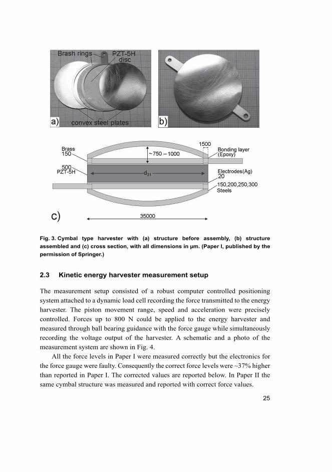
Fig. 3. Cymbal type harvester with (a) structure before assembly, (b) structure
assembled and (c) cross section, with all dimensions in µm. (Paper I, published by the
permission of Springer.)
2.3 Kinetic energy harvester measurement setup
The measurement setup consisted of a robust computer controlled positioning
system attached to a dynamic load cell recording the force transmitted to the energy
harvester. The piston movement range, speed and acceleration were precisely
controlled. Forces up to 800 N could be applied to the energy harvester and
measured through ball bearing guidance with the force gauge while simultaneously
recording the voltage output of the harvester. A schematic and a photo of the
measurement system are shown in Fig. 4.
All the force levels in Paper I were measured correctly but the electronics for
the force gauge were faulty. Consequently the correct force levels were ~37% higher
than reported in Paper I. The corrected values are reported below. In Paper II the
same cymbal structure was measured and reported with correct force values.

26
Fig. 4. a) Photograph of positioning system (left side), piston, sample, ball bearing and
the force gauge (right side). b) Schematic of measurement setup. (Paper II, published
by the permission of Institute of Physics - Journals.)
2.4 Structural optimisation of cymbal type energy harvester
Next paragraphs describe structural optimisation of the harvester for customised
force profile and tailored input force effects to harvested output energy. Many
mechanical and electrical factors influence the efficiency and the amount of energy
that can be harvested from a cymbal type energy harvester. To determine the
optimum steel thickness the shape of the steel end caps and the cavity beneath were
designed to be similar for all samples. This was because the profile of the end caps
and the cavity height strongly effect the strain experienced by the piezoelectric
ceramic and consequently the energy harvesting gain. Secondly, the attachment
area between the piezoelectric disc and the end caps has a major effect on the
transducer functionality. To minimize this variable laser machined brass contacts
offered a precise and equal bonding area for each sample. Also small plastic
cushions (Ø2.50 mm) were glued on the middle point of each end cap to direct the
force cycles in a repeatable manner. The harvester output was measured with
sinusoidal compression cycles at 1.19 Hz. The voltage from the harvester was then
directed through a rectifier circuit (Fig 5.) and the average raw power was
calculated as a function of electrical load. The harvester electronics in Fig. 5

27
consisted of a rectification circuit using Schottky diodes, a 1 µF capacitor and an
electrical load RL across which the voltage was measured.
Fig. 5. Harvester electronics.
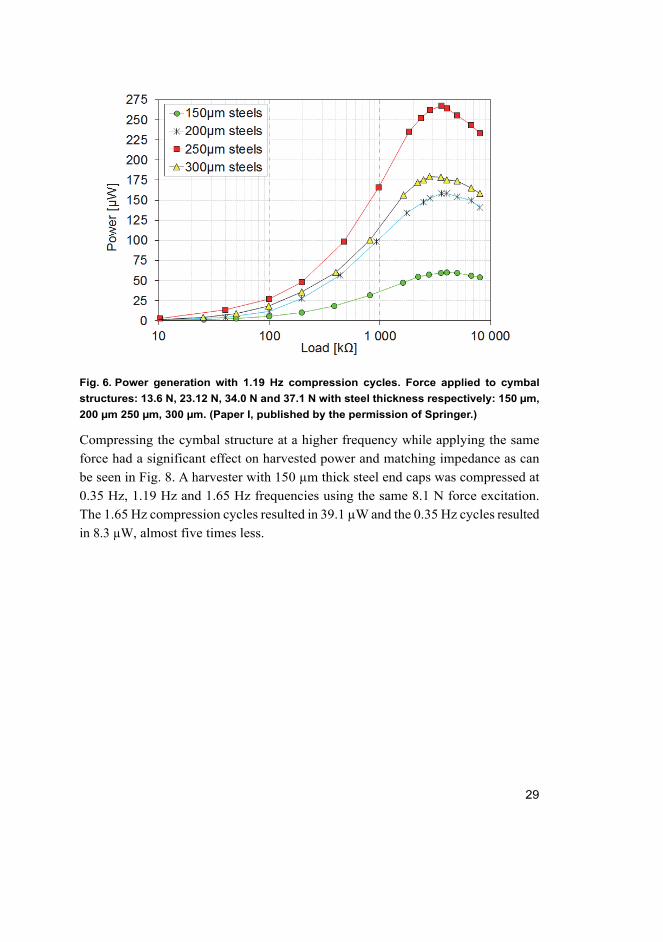
Fig. 6 shows the results of each sample with different end cap thickness. A cymbal
harvester with 250 µm steel end caps was found to produce the highest power (0.27
mW) with 34.0 N of compression force as measured with the harvester electronics.
End caps with 300 µm, 200 µm and 150 µm thickness resulted in a harvested power
of 0.18 mW, 0.16 mW and 0.062 mW respectively and the associated force
amplitudes were 37.1 N, 23.1 N and 13.6 N. Although the spring constants of the
cymbal structures and the exact input energy were not determined, it is still safe to
assume on the basis of the measured output average power and force levels that the
sample with 250 µm end caps was also the one with the highest efficiency. Fig. 7
shows the voltage and power from the 250 µm cymbal harvester measured directly
across an electrical load (2.6 MΩ) under applied cycles of compression. The
calculated average raw power (dashed line in Fig. 7) in this setup was over two
times higher at 0.66 mW compared to the 0.27 mW power measured with the
harvester electronics. This can be explained by the efficiency of the electronics. The
measured power of 0.66 mW corresponded to a power density of 1.37 mW/cm3 for
the piezoceramic element.
In the past decade a great deal of research has been conducted on electronic
circuits for energy harvesting as they are an essential part of the final application.
Piezoelectric energy harvester output current and voltage depend on excitation and
therefore they are irregular as a function of time. Because of this irregular voltage
an AC-DC rectifier interface circuit is required to produce a DC power supply. With
different harvester mechanics and ambient energy sources a harvester output
amplitude, frequency and predictability can be anything from pulsed random bursts

28
of bipolar voltage to a precisely known sinusoidal voltage with a constant amplitude
and frequency. For these reasons it is essential to design the electronics to match
the voltage output and the impedance of the harvester and also to match the
specifications of the final application.
Many of the current research investigations utilize an SSHI (Synchronized
Switch Harvesting on Inductor) rectifier to harvest energy very efficiently. It is one
of the most energy-efficient circuits with ideally no charge wastage. SSHI was first
introduced by Guyomar in [46]. Later it was developed to be self-sufficient with a
very low power demand in the micro watt range and the capability to start up
independently by detecting zero crossing of the input current [47–49]. Other
promising energy harvesting circuits are SECE (Synchronous Electric Charge
Extraction) and DSSH (Double Synchronized Switch Harvesting). They are not
sensitive to the electrical load and improve the harvested power gain by around
400% and 600% respectively compared to the standard DC mode technique (STD
DC) where a regulated output voltage is delivered through a full-wave diode bridge,
a capacitor is used filter the output voltage and the power is related to the load
impedance. [50–52]
The majority of publications on energy harvesting usually report the average
power or raw power gained without any harvesting electronics as it makes
comparison between similar techniques or components much easier. In this thesis
from now onward the average power and its comparisons refers to this raw power
calculated from the voltage across an optimal load.
29
Fig. 6. Power generation with 1.19 Hz compression cycles. Force applied to cymbal
structures: 13.6 N, 23.12 N, 34.0 N and 37.1 N with steel thickness respectively: 150 µm,
200 µm 250 µm, 300 µm. (Paper I, published by the permission of Springer.)
Compressing the cymbal structure at a higher frequency while applying the same
force had a significant effect on harvested power and matching impedance as can
be seen in Fig. 8. A harvester with 150 µm thick steel end caps was compressed at
0.35 Hz, 1.19 Hz and 1.65 Hz frequencies using the same 8.1 N force excitation.
The 1.65 Hz compression cycles resulted in 39.1 µW and the 0.35 Hz cycles resulted
in 8.3 µW, almost five times less.

30
Fig. 7. Voltage and power gain measured from cymbal type harvester with 250 µm thick
steel end caps. Compression parameters: 1.19 Hz and 24.8 N. (Paper I, published by the
permission of Springer.)
Fig. 8. Calculated power as function of electrical load from the cymbal type energy
harvester with 150 µm steel end caps at different compression frequencies. (Paper I,
published by the permission of Springer.)
The next investigation in Paper II focused on how a more impulse type compression
profile (walking profile) affected the harvested energy output compared to
sinusoidal compression cycles with smooth repetitive oscillations when both cycle

31
profiles were executed with the same frequency and force amplitude. A casing was
made for the cymbal structure and fitted inside a shoe heel (Fig. 9). The
piezoelectric element with silver electrodes (PZT-5H), diameter of 35 mm and 0.5
mm thick, was the same as in Paper I. Casing lids and small plastic cushions
between the lids and the steel end caps (250 µm thick) directed the force from the
heel of the foot to the middle point of the cymbal harvester. By this means the force
was directed into the harvester component in the same way as in the computer
controlled piston cycles.
Fig. 9. Harvester inside the casing and fitted inside a shoe heel. (Paper II, published by
the permission of Institute of Physics - Journals.)
The voltage output from the harvester inside the shoe heel was measured when
walking at a constant pace close to 1 Hz frequency. The harvester was then
compressed with the piston by adjusting the acceleration, deceleration and
frequency to match the output voltage measured from actual walking. Fig. 10 shows
the piston movement adjusted to match the actual accelerations during walking.
The cycle starts with a fast compression that reflects the shoe heel hitting the ground.

32
A small pause occurs before the piston releases the pressure at a slower deceleration
reflecting the heel being lifted off the ground. A longer pause takes place before the
heel hits the ground again and the cycle starts again from the beginning. The average
frequency of a brisk walk was found to be close to 1 Hz, which has also been
reported by other publications [9, 25]. The harvester voltage generated by the piston
using the walking profile cycles and the actual voltage output from walking can be
seen in Fig. 11. The voltage output of the harvester from walking matched very
closely to that made with the piston. The voltage peaks were close to two times
higher when the heel of the foot hit the ground compared to the foot lifting from
the ground. The major part of average power generation was produced at this
moment as the power is related to voltage as P=U2/R, where P is power, U is voltage
and R is the electrical load.
Fig. 10. Piston velocity and movement with the walking profile as a function of time.
(Paper II, published by the permission of Institute of Physics - Journals.)

33
Fig. 11. Generated voltage from actual walking and from the walking profile using piston
for compression cycles. (Paper II, published by the permission of Institute of Physics -
Journals.)
The recorded force profile in the creation of the walking profile cycles was then
used to analyse the cymbal harvester with a Finite Element Method (FEM) model
using different displacements in compression. Cymbal type harvesters have been
previously modelled with FEM using sinusoidal input energy and different
mechanical configurations [36, 44]. However, simulations comparing an actual
walking profile and sinusoidal force input have not previously been investigated in
terms of energy harvesting. Fig. 12 shows the measured (with the piston) and
simulated power across a load resistance of 2.63 MΩ that was found to be the
optimal load in Paper II. The maximum average power of 780 µW was measured
with 1.5 mm walk profile compressions at 1.0 Hz cycles corresponding to 1.62
mW/cm3 energy density in the piezoelectric element.
Previously (Paper I) with a sinusoidal compression profile at 1.19 Hz frequency
and 1.1 mm compression the maximum of 660 µW average power was calculated
for the same type of harvester. This power corresponds to an energy of 555 µJ per
cycle. With the walking profile and the same 1.1 mm compressions 650 µJ was
recorded from a single cycle, which is over 17% greater energy.

34
Fig. 12. Measured and simulated power output using the walking profile as a function
of compressive displacement. (Paper II, published by the permission of Institute of
Physics - Journals.)
Kim et al. showed that with an optimal matching load the generated electrical
power is linearly proportional to the frequency as long as the vibration remains at
a high frequency with constant force and with negligible damping. This means that
the same amount of energy per cycle is obtained regardless of frequency. However,
it should be noted that in this case the cymbal type energy harvester was operated
below resonance (~13.5 kHz). [36] Results from Paper II may be compared to
similar research in the field of cymbal type energy harvesters although the
robustness of the structures and the AC to DC conversion efficiency of the
harvesting electronics must also be considered. Kim et al. measured a cymbal
structure (Ø 29 mm) with different end cap thicknesses and 1 mm thick piezoelectric
materials using a mechanical shaker. Approximately 100 mW power was measured
from the cymbal structure under high pre-stress and at a much higher frequency of 200
Hz. This corresponds to 760 µJ/cm3 per cycle which is less than half that reported in
Paper II (1630 µJ/cm3). Also Ren et al. measured a cymbal structure (Ø 26.6 mm) with
a mechanical shaker using 0.7 mm thick single crystal piezoelectric material. A proof
mass of 17.0 g was glued on top of the cymbal and 14 mW of power was generated at
the resonance frequency of 500 Hz. This corresponds to only 72 µJ/cm3 of power
density per stress cycle due to the high frequency. Yan et al. stated that some of the
mechanical energy expended in the metal end caps could be directed more efficiently

35
to the piezoelectric material by fabricating radial slots in the end caps. The slotted
cymbal was manufactured from PZT 5H disc (35 mm in diameter, 2 mm thick). Same
diameter 0.5 mm thick brass end caps were slotted and bonded on the piezoceramic
disc. The energy harvester was measured at 120 Hz with a mechanical shaker under 30
N bias. Maximum output power was measured at 16 mW which corresponds to 69
µJ/cm3 of power density per stress cycle. The article states that the slotted cymbal
average power was about ~67% more than that of the original cymbal transducer. In
Paper I almost the same power gain difference (~68%) was measured for a cymbal with
250 µm and 200 µm end caps. From these results it can be concluded that at least some
of the same benefits of the slotted cymbal could be also achieved by optimising the end
cap thickness. [35, 37, 38, 44]
In Fig. 13 the power outputs of the sinusoidal compression and walking profile
compression cycles are presented. The walking profile produced an average of 25.9%
greater power compared to that of the sinusoidal profile with the same compression
distance and frequency. The walking profile compressed the cymbal structure with
a rapid acceleration at the beginning of each cycle. This generated a high voltage
level response from the piezoelectric element as can be seen from Fig. 11. The same
effect has been reported by Okayasu et al. who studied the electric power
generation of a piezoelectric plate under various cyclic loading conditions. Their
results showed that at low frequencies, from 0.1 to 10 Hz, square wave compression
cycles having a higher acceleration generated much higher voltage levels than
triangular and sinusoidal wave modes. This behaviour could be related to the
internal resonance of the piezoelectric material as a walking profile or square wave
applied to the material might have a higher mechanical to electrical coupling
coefficient than slower sinusoidal excitations. [53, 54]

36
Fig. 13. Power outputs of the harvester with sinusoidal and walking profile excitations
as a function of compression distance.

37
3 Diaphragm type energy harvester
3.1 Diaphragm type transducers
A wide range of membrane or diaphragm type actuators has been developed for
numerous applications during the last hundred years. Diaphragm type transducers
consist of a piezoelectric thick or thin film which is embedded in an oscillating
membrane (Fig. 2). The first underwater sound detection devices (hydrophones)
were developed for submarine detection during the First World War in 1917. A
piezoelectric membrane turned mechanical vibrations into electrical signals and
converted them to soundwaves in earphones. After the War, membrane type
piezoelectric transducers were widely studied in the early 1930’s for use in
microphones, loudspeakers, recorders etc. [55, 56]. More recently research has
concentrated more on (MEMS) based devices where diaphragm type transducers
are useful in, for example, microfluidic control systems such as micropumps, valves
and inkjet printers [57–60]. There are also many optical applications that utilize
diaphragm type actuators, such as devices for deforming mirror surfaces [61, 62].
Within the last decade piezoelectric diaphragm type energy harvester designs
and models have been presented. Publications have investigated their feasibility for
energy harvesting from ambient energy sources of alternating pressure such as
fluctuations of blood pressure, tyre pressure variations, in micro combustion
chambers, and in other industrial devices [15–17, 63–72]. Also, alternating
mechanical forces or vibrations can be utilised by piezoelectric diaphragm energy
harvesters, as described in various publications [14, 73]. Many aspects in the design,
manufacture and electrical realization need to be considered to fully exploit the
potential of the diaphragm type energy harvester. Electrical, mechanical, material
choice and design parameters all determine the efficiency of transformation of
mechanical energy into electrical energy. These consists at least of boundary
conditions, choice of bonding layer, temperature variations, ratio of passive and
active layers both in diameter and in thickness, pressure or compression profile,
poling profile and direction, level and type of pre-stress and lastly the efficiency of
the associated electrical circuitry. [64, 65, 67–70, 74–80]
In this work the effect of pre-stress on efficiency and the amount of the
maximum harvested energy was investigated with a unimorph type diaphragm. A
pre-stressed bimorph type energy harvester was used to investigate power density
maximization related to piezoelectric material volume, functionality of a stacked

38
structure and the benefits of pre-stressing with a stacked structure. A unimorph type
transducer consists of a piezoelectric layer and a passive layer beneath it while
bimorph transducers have a passive layer in the middle and piezoelectric layers on
both sides. Pre-stressing was originally developed to enhance piezoelectric
coefficients for actuators or to enhance mechanical robustness and
electromechanical efficiency, for example in stack type actuators. In unimorph type
actuators the pre-stress can be generated by utilizing layers with different thermal
coefficients and/or sintering shrinkages. In the cooling process the variances in
thermal expansion or shrinking between the passive and active material inflict
anisotropic internal stresses that differ across the thickness of the transducer. As a
result of these stresses the piezoelectric coefficients are enhanced [81–83]. Pre-
stressing has been proven to enhance piezoelectric coefficients not only in actuators
but also in energy harvesters. Energy harvesters that exploit mechanical vibrations
have been widely studied and in some publications a pre-stressing mass or
mechanical axial pre-stress has been noticed to improve power output [13, 14, 35,
71, 72, 76, 84]. In this thesis pre-stressing effects were investigated when an energy
harvester was submitted to compression cycles at 1 Hz. Electro mechanical effects
related to power generation and efficiency were observed as an adjustable
mechanical spring setup acted on the diaphragm type piezoelectric energy harvester.
This setup provided a possibility to control precisely the pre-stressing state and to
investigate its impact on the energy harvesting performance.
3.2 Unimorph diaphragm energy harvester design
The unimorph type piezoelectric diaphragm energy harvester was designed with a
mechanical pre-stressing mechanism as shown in Fig 14. Dimensions and
parameters of the piezoceramic can be seen in Table 1. A piezoelectric disc (PSI-
5A4E, Piezo Systems, INC.) with a thickness of 191 µm, 250 µm thick steel, 560
µm thick polycarbonate clamping rings and 100 µm thick steel plate were all laser
machined from bulk materials. The piezoelectric disc (Ø 34.5 mm, radius R1) was
first glued on the 100 µm thick steel plate (Ø 45.5 mm) with a thin adhesive layer
of ~10 µm. A thin adhesive layer was pointed out to be essential by Mo et al. in
diaphragm type energy harvester designs, thus keeping the bonding layer effect to
a minimum and ensuring a higher energy harvesting efficiency [70]. A small drop
of conductive silver paint was mixed into the glue to confirm a good electrical
contact between the piezoelectric disc and the steel plate on the bottom and the 50
µm brass foil on top. These two formed the top and bottom electrodes for the

39
factory polarized piezoelectric disc. Steel and polycarbonate clamping rings
together with 16 screws (Ø 1.5 mm) were used to guarantee a robust and precise
clamping region from Ø 45.5 mm (radius R3) to Ø 39.0 mm (radius R2, Fig. 14)
for the steel plate. Boundary conditions were related to the clamping conditions on
the edge of the passive layer. This edge condition had a significant impact on the
overall electromechanical coupling coefficient and generated voltage. In general, a
simply supported boundary condition can deliver higher electromechanical
coupling and therefore lead to higher efficiency. In practice, ideal boundary
conditions are difficult to achieve and also at higher stresses there is only a small
difference between the clamped and simply supported cases [67, 77].
Fig. 14. Piezoelectric diaphragm harvester. a) Construction and adjustable rings for
clamping, b) schematic view of the harvester and c) harvester attached to pre-stressing
mechanism. (Paper III, published by the permission of Institute of Physics - Journals.)
Table 1. Piezoelectric material properties and energy harvester diaphragm dimensions.
(Paper III, published by the permission of Institute of Physics - Journals.)
PSI -5A4E d33 d31 k33 k31 Q C
390 pm/V -190 pm/V 0.72 0.35 80 ~72.5
Dimensions: R1 R2 R3 tp ts
17.25mm 19.50 mm 22.75 mm 191 µm 100 µm

40
A pre-stressing mechanism was assembled on the underside of the steel plate (Fig
15). This consisted of a spring inside an aluminium tube with four slots for a metal
plate that held the spring aligned. The positions of the metal plate together with an
adjustable jig length were used to adjust the pre-stressing state (bias force) by
regulating the gap of the spring cavity. Small Ø3 mm polycarbonate cushions were
glued on both sides of the diaphragm to align the piston (Fp) and pre-stressing
spring (Fs) forces. Fig. 15 shows a simplified schematic of the experimental setup
which was the same as that used in the cymbal type harvester measurements (Fig.
4) with the exception of the pre-stressing mechanism. The harvester was
compressed with computer controlled cycles and with the same walking profile as
that described earlier in the cymbal type harvester measurements. The walking
profile imitated the force occurring under the heel of a foot during actual walking.
Fig. 15. Schematic of the measurement setup. (Paper III, published by the permission of
Institute of Physics - Journals.)
The harvester voltage output was obtained through the d31 coefficient as the strain
was orthogonal to the polarization axis. The optimum electrical load was
determined from the output voltage by calculating the power generated.
Measurements were made to determine the maximum efficiency of the harvester
while altering the pre-stressing state and comparing mechanical input energy to
electrical output energy. Also the maximum power output in relation to the volume

41
of active material was measured and compared to other similar type energy
harvesters or harvesters working in the same frequency region.
3.3 Results of the unimorph type energy harvester
The optimum electrical load was determined by compressing the harvester with
walking profile cycles. The voltage output from the harvester was measured as a
function of electrical resistive load and the power output was calculated (Paper III).
An optimum load resistance of 1.25 MΩ was selected to be used for the power
output measurements with different pre-stressing states. Before energy harvester
measurements the spring constant of the pre-stressing spring and the diaphragm
was measured. The pre-stressing spring was initially measured with weights and
later by compressing with the computer controlled piston and the diaphragm. Fig
16 shows the nonlinear spring constant of the diaphragm as measured from -0.8
mm to 1.1 mm by bending in both directions from the flat state together with the
behaviour of the pre-stressing spring as measured from 1 mm to 20 mm. The figure
also shows trend line equations for both spring constants calculated with Excel
software. These results showed linear behaviour of the pre-stressing spring constant
and good comparison between weight and piston measurements.

42
Fig. 16. Spring constants measurements of the pre-stressing spring and the diaphragm
and trend line (black lines) equations for both.
The energy harvesting potential was first measured without bias force and then with
pre-stressing forces of 8.3 N, 13.3 N, 17.6 N and 22.5 N opposite to the compression
direction. Compression cycles were performed at 0.96 Hz starting from a 0.3 mm
cycle and increasing the compression length by 0.1 mm increments. A small initial
force of ~2.0 N was applied via the piston to eliminate any slack in the structure.
Due to this initial pressure, the compression cycles started from 0.05 mm and
reached a maximum bending of 1.05 mm where the power started to saturate
strongly as a function of force.
Fig. 17 illustrates the basic principle of the compression cycles with and
without a pre-stress. Compression cycles of 1.00 mm for 0 N and for 17.6 N bias
forces (pre-stress) are illustrated with the black arrows. Red arrows indicate the 0
N and 17.6 N bias forces. Due to the non-linear spring constant (Fig. 16) of the
diaphragm 52.8 N of force was required to bend the diaphragm from 0.05 mm to
1.05 mm. With the 17.6 N bias the starting point of the cycles was -0.52 mm towards
pre-stress and the 1.00 mm deflection only required 24.2 N of force which was less
than half that compared to the case without pre-stress.

43
Fig. 17. Illustration of the 1.00 mm compression cycle with a) 0 N and b) 17.6 N pre-
stressing force bias.
Fig. 18 shows the great enhancement in voltage generation due to pre-stressing.
The curves compare the energy harvester at zero pre-stress and at 17.6 N pre-
stressing states, both bent with 1.00 mm compression cycles. The voltage was
measured across the optimal load of resistance 1.25 MΩ. The generated peak
voltage was ~38% higher in the pre-stressed case and the peak force needed to
achieve this was only ~46% of that for the non-pre-stressed state. Non-linear
behaviour was observed in the force curves where the compression cycle distance
was longer than the curvature depth of the diaphragm created by the pre-stress (Fig.
17). For example, in Fig. 18 with the 17.6 N pre-stress, the non-linear point of the
force curve was at the halfway point of 1.00 mm compression cycle (~0.65 s),
although the piston retraction speed was constant at 3 m/s. This occurs when the
compression cycle goes over the flat state of the diaphragm.

44
Fig. 18. Voltage and force outputs of non-pre-stressed case and with 17.6 N bias from 1
mm compression cycle. (Paper III, published by the permission of Institute of Physics -
Journals.)
Fig. 19 presents the harvested power as a function of compression distance and Fig.
20 shows harvested energy as a function of compression energy for each pre-stress
state. The harvested power in watts was calculated from the measured voltage
across the matching electrical load resistor and the energy output from the
integrated power in watts within a known time period. The input energy (Ein) at
compression, equation 1, was calculated for all force biases by integrating over the
nonlinear spring constant of the diaphragm and adding the pre-stressing linear
spring energy from the compression distance (x) in each case where x=x2-x1
meaning the ending and starting points respectively.
(1)
With 17.6 N pre-stress and with 1.5 mm compression distance the energy harvester
generated a maximum average power of 1079 µW or an energy of 1.12 mJ/cycle.
The same pre-stressing bias was also the best in measurements of power versus
compression distance, with 771 µW/mm achieved at 1.1 mm cycles (Fig. 19). When

45
comparing the cases without pre-stress (0 N bias) and with 17.6 N force bias the
energy harvesting enhancement can be clearly seen. The maximum compression
distance of 1.0 mm with 0 N and 17.6 N bias generated 438 µW and 752 µW,
respectively with the same cycle. This is a ~72% increase in power generation due
to pre-stressing. In addition, only one third of the energy input to the system was
needed with the 17.6 N compared to 0 N bias, consuming only 6.2 mJ instead of
18.9 mJ. This is due to the non-linear spring constant of the diaphragm and the fact
that the pre-stressing cycle was performed over the flat region of the diaphragm
from -0.52 mm to 0.48 mm, reaching the diaphragm flat state in the middle of the
compression cycle. As the zero bias cycle started from the flat state of the
diaphragm and the energy demand to bend the diaphragm grows exponentially,
hence the profound difference between 0 n and 17.6 N pre-stressing states is
explained. In addition, pre-stressing affects the piezoelectric coefficients of the
piezoelectric material and improves the harvested energy radically. [85–87]
Fig. 19. Harvested power as a function of compression cycle distance with different
force biases. (Paper III, published by the permission of Institute of Physics - Journals.)

46
Fig. 20. Harvested electrical energy as a function of compression energy per cycle.
(Paper III, published by the permission of Institute of Physics - Journals.)
In Fig. 21 the efficiency curves for each pre-stress state as a function of harvested
energy are shown. Efficiency was calculated by dividing the output energy by the
input energy as seen in equation 2. These calculations clearly show the benefits of
the pre-stressing effects.
. 100% (2)
Without pre-stress the energy harvesting efficiency from 0.3 mm to 1.0 mm
compression started from 10.1% and continuously decreased to 2.4%. This was due
to the non-linear spring constant of the diaphragm (Fig. 16) as the input energy
required to bend the diaphragm increased exponentially as a function of distance.
In the pre-stressed cases all the efficiencies first increased after the 0.3 mm
compression cycle. The input energy required to bend the structure was mostly
determined by the pre-stressing linear spring up to the point where the compression
distance equaled the pre-stressing distance. A major difference from the non-pre-
stressed case was that the saturation of the efficiency started after 0.7 mm (8.3 N
bias) and at 1.1 mm (22.5 N bias) compression, whereas in the non-pre-stressed

47
case the saturation had already started before 0.3 mm. The 13.3 N pre-stress
produced the highest efficiency and, in contrast to the case without pre-stress, after
the 0.3 mm compression efficiency (5.1%) it still increased. With 0.8 mm
compression the efficiency was 14.7% and was still 5.8% with a 1.4 mm
compression cycle. The highest 14.7% efficiency was achieved with a compression
energy of 3.776 mJ which resulted in 0.556 mJ of harvested energy.
Fig. 21. Efficiency as a function of harvested energy per compression cycle. (Paper III,
published by the permission of Institute of Physics - Journals.)
It is essential to harvest wasted energy as efficiently as possible so it is sensible to
design and optimise the diaphragm type harvester to work in the most efficient
region of its characteristics. Based on these results this can be only done when the
failure limit and the input energy available to the system are known. Although more
energy could be harvested with the maximum applied pre-stress and with the
maximum bending used in the measurements this might lead to serious discomfort
in the case of shoe implementation. In addition, the lifetime of the harvester would
be more likely to be shortened as higher stresses would wear out parts more rapidly.
To reach the amount of energy needed from the harvester to support that required
by the electronics the unimorph design could be realized as a multilayer structure

48
in contrast to the extreme bending of the structure from maximum pre-stress to
maximum compression distance. To enhance the energy density and efficiency
even further the layers could be designed with bimorph layers as described in the
next section and in Paper IV. Also, adjustment of the thickness ratio of passive and
active material to the optimum could further improve the stress distribution to the
piezoelectric ceramic and hence the gain of harvested energy. This is because too
thin a passive layer could collapse under stress and too thick a layer would decrease
the total deflection [16, 70]. The thickness of the active piezoelectric layer can be
also adjusted with a nonlinear approach according to El-Sabbagh et al. [80].
3.4 Multilayer bimorph energy harvester design
As in the unimorph design (sections 3.2 & 3.3) all parts were laser machined except
for the pre-stressing spring (Fig. 22). The bimorph harvester design had the same
outer diameter of 45.5 mm as did the unimorph harvester. The multilayer bimorphs
consisted of four 50 µm thick steel plates with 191 µm thick PSI-5A4E (PZ-5A,
Piezo Systems Inc.) piezoelectric ceramics (Ø 34.5 mm) attached on both sides with
conductive epoxy. Small polycarbonate (PC) cushions 500 µm thick (Ø 3.5 mm)
between each layer directed the applied force from the piston to the middle point
and also isolated the layers from each other. Copper tape was used to make
electrical contacts to each of the piezoelectric discs. Clamping rings made from 300
µm thick steel and 560 µm thick PC rings were used to create a precise and robust
construction. The overall thickness of four bimorph diaphragms with cushions and
clamping rings was ~4.0 mm. A casing housing the pre-stressing mechanism was
made from polyoxymethylene (POM) and the structure was sealed with 1.5 mm
polycarbonate (PC) covers. The cavity depth of casing for the pre-stressing spring
from the bottom cover to the bimorph layers was designed to direct a ~58 N pre-
stress. The whole closed harvester assembly was 15 mm thick and was clamped
together with 16 screws.

49
Fig. 22. Laser machined energy harvester parts. (Paper IV, published by the permission
of John Wiley and Sons.)
Electrical contacts were guided out from the casing with wires. These can be seen
in Fig. 23 where the energy harvester is embedded into a running shoe. A round
hole was carved into the shoe where the harvester was placed and locked in place
with silicone rubber. The voltage output was first measured when running and
walking on a treadmill at different speeds. Next the multilayer bimorph harvester
was removed from the shoe and tested with the computer controlled piston setup
described earlier in the cymbal and Unimorph harvester measurements (Papers II
& III). A simplified cross-section of the bimorph harvester during the measurement
procedure can be seen in Fig. 24. This illustrates how the bimorph layers stacked
up inside the holster and were connected with each other through the PC cushions.
It can be also seen how the layers bent towards the holster top cover due to the pre-
stress and how the layers bent in the opposite direction as a result of the force input.

50
Fig. 23. Harvester fitted inside the running shoe. (Paper IV, published by the permission
of John Wiley and Sons.)
Fig. 24. Simplified schematics of the multilayer bimorph structure with the pre-stress
and measurement procedure. (Paper IV, published by the permission of John Wiley and
Sons.)
3.5 Measurement results of the multilayer bimorph type harvester
First the energy harvester was fitted inside a running shoe and the voltage output
was measured over the optimum 147 kΩ load. The weight of the harvester was ~44
g, being hardly noticeable during the treadmill tests as it was inside the silicone
rubber and under the shoe insole. Fig. 25 shows the voltage output when walking
with speeds of 4, 6 and 8 km/h and running with speeds of 10, 12 and 14 km/h on
a treadmill. The step frequency increased as the treadmill travel speed was increased.

51
Also the voltage output increased as the foot directed higher kinetic forces to the
bimorph layers inside the shoe heel. Increasing the travel speed could be seen from
the voltage curves as they became sharper at the impact moment and also when the
foot roses and weight was lifted off the heel. The measured power increased
significantly as a function of the walking speed. In the case of running, the power
output improved between 10 km/h and 12 km/h but saturated slightly at 14 km/h.
This could be a result of a change in running technique where the weight was moved
from the heel towards the ball of the foot when running faster. Table 2 shows the
average raw powers from a ~20 second period for each travel speed. The highest
average power of 6.01 mW was measured when running at 12 km/h where the
instantaneous power was as high as 83.82 mW.
Voltage curves measured at walking speed in Fig. 25 show a small voltage peak
at the half point of the cycle. This represents the shock from the left foot hitting the
ground and causing a small vibration in the harvester on the right foot heel. This
small voltage peak is missing from the curves recorded at running speed as the right
leg is up in the air when the left leg hits the ground. These tiny voltage peaks show
the sensitivity of the harvester and a possibility that it could also be used to monitor
a person’s walking to correct any harmful techniques. The treadmill test showed
that the harvester module was very robust and a feasible implementation but was
also very sensitive to even small fluctuations in pressure.

52
Fig. 25. Harvester voltages across 147 kΩ load during treadmill tests when a) walking
at a speed of 4, 6, 8 km/h and b) running at a speed of 10, 12, 14 km/h. (Paper IV,
published by the permission of John Wiley and Sons.)
Table 2. Average powers from walking and running at different speeds and the highest
recorded power output from computer controlled piston measurements. (Paper IV,
published by the permission of John Wiley and Sons.)
Impulse Power [mw] Frequency [Hz]
Walk 4 km/h
Walk 6 km/h
Walk 8 km/h
Run 10 km/h
Run 12 km/h
Run 14 km/h
Piston 1.8 mm
2.06
3.65
5.32
4.29
6.01
5.46
11.3
0.89
1.07
1.19
1.43
1.52
1.58
1.07

53
It was found out that the multilayer bimorph type energy harvester was capable of
generating much more energy than that measured in the treadmill tests. A significant
amount of the input energy was wasted in the top cover and into the shoe insole and
the bimorph layers’ stiffness was not optimal for the weight of the test person. It was
also found that different walking techniques with different weight distributions from
person to person could significantly affect the amount of harvested energy. All these
variables were considered in the next set of measurements. The harvester’s
performance was measured with the computer controlled piston cycles using the
walking profile. The top cover of the harvester holster was removed and the
harvester voltage output was measured at 1.07 Hz. This frequency corresponded to
the treadmill tests at 6 km/h and the voltage output from the treadmill was also in
line with the voltage curves measured with piston cycles.
Fig. 26 shows the individual voltage gain of each bimorph layer across 634 kΩ
(the optimum load for a single bimorph layer) measured with a 1.9 mm
compression cycle. The voltage curves maintained the same level of amplitude due
to the robust construction and the precision of the piston. Also the voltage outputs
were maintained in the same phase between each bimorph layer. This is vital to keep
charge cancellation to a minimum [14]. The mechanical pre-stress kept the bimorph
layers in contact which each other at all times during the compression cycles. This
was the key to the small phase difference. Pre-stress had also been proved earlier to
enhance the physical compression distance and efficiency in unimorph type
diaphragm harvesters (Paper III). Piezoelectric actuators had likewise been able to
achieve larger displacements and piezoelectric coefficients due to pre-stress [81–
83, 88].

54
Fig. 26. Voltage outputs of individual bimorph layers across 634 kΩ load measured with
a 1.9 mm compression at 1.07 Hz. (Paper IV, published by the permission of John Wiley
and Sons.)
To measure the maximum potential of the harvester all the layers were then
connected in parallel and the voltage was measured across the optimum 147 kΩ
load. The cycle compression distance was increased from 0.6 mm all the way to the
cracking point at 2.0 mm in 0.1 mm steps. In the initial state the bimorph layers
were bent ~0.85 mm with the 58 N pre-stress from the midpoint. With the
maximum 2.0 mm piston cycle the layers bent ~1.15 mm in the opposite direction
from the flat state. Fig. 27 presents the calculated average powers as functions of
compression distance. The compression force was measured with the force gauge
as described earlier and the compression energy was calculated by integrating the
force curve over the compression distance. The maximum power output of 11.30
mW was measured with a 1.8 mm compression cycle at 1.07 Hz. This was achieved
with 223.2 N of force which corresponded to 179 mJ of mechanical energy. The
highest harvested energy output from a single cycle was 10.56 mJ and the
calculated power density for the piezoelectric material was 10.55 mW/cm3. With
higher forces and longer compression distances the power output started to saturate
as the piezoelectric ceramic of one of the bimorph layers became cracked. The above
reported power density of the piezoelectric multilayer bimorph energy harvester is
the highest reported in this frequency range.

55
Fig. 27. Harvested power, compression force and energy as a function of compression
distance, with all bimorphs connected in parallel. (Paper IV, published by the permission
of John Wiley and Sons.)
The efficiency for the harvester was calculated by dividing the harvested energy
output by the compression input energy. The highest efficiency of 9.9% was
calculated from a 1.2 mm compression cycle. This can be further enhanced with
optimal pre-stress as proven in Paper III. Also the thickness ratio of the passive and
active layer has a large effect as mentioned earlier. The amount of energy harvested
can always be improved by adding more piezoelectric layers and by increasing the
dimensions of the layers. In the case of the running shoe implementation the
maximum piezoelectric disc diameter could be increased to ~Ø50.0 mm thus
doubling the volume of the piezoelectric material.
Table 3 compares earlier reported cymbal and diaphragm type energy
harvesters from different applications and from various working frequency ranges.
The cymbal structure can sustain high force inputs even at high frequencies as
demonstrated by Kim et al. where the harvester was under a vibration force of 70
N from 10 – 200 Hz with a power output up to 100 mW [36]. This corresponded to
500 µJ per cycle which is ~64% of the 784 µJ reported in this thesis from the
cymbal type harvester. The diaphragm type harvesters investigated in this thesis
produced ~10.5 mJ of energy for each cycle which is significantly higher than that
reported in other publications. The only reported publication that comes close to
these numbers refers to the double dimorph Thunder TH-6 transducer used by

56
Shenk et al. inside a shoe heel which produced 9.3 mJ. But the power density for
the piezoelectric ceramic volume of the bimorph stack harvester was over two times
higher at 10.55 mW/cm3 compared to 4.41 mW/cm3 of the dimorph Thunder
harvester. Adjustable pre-stressing offers many design features and furthermore an
advantage over the Thunder TH-6R transducers. These cannot be reverse bent
without cracking of the piezoceramic as it is designed to work from a curved pre-
stressed form to a flat form. [25]
Table 3. Comparison of piezoelectric energy harvesters.
Ref. Application Size: active
material [mm]
Material [Hz]a [µJ]b [mW/cm3]c [mW]d
Zhao [71] Thermo-acoustic Diaphragm Ø 63.5,
tp: 2 x 0.1905
PZT-5A 180 1.2 0.17 0.21
Wang [14] Diaphragm array
in resonance
Diaphragm Ø50.0,
tp: 0.20
PZT 150 56.7 86.58 8.50
Mo [16] Pressure loaded
diaphragm
Diaphragm Ø25.4,
tp: 0.127
PZT-5H 1 128.0 1.99 0.13
Shenk [25] Dimorph: TH-6R
transducer (shoe
heel)
Area: 50x50,
tp: 2 x 0.381
PZT 0.9 9333.3 4.41 8.40
Shenk [25] Multilayer(2x8)
Piezoelectic-
foil (shoe insole)
Hexagonal shape:
6500 mm2,
tp: 16 x 0.028
PVDF 0.9 1444.4 0.45 1.30
Li [89] Free edge bimorph
(wind energy
harvester)
Cantilever:
16 x 72,
tp: 0.41
PVDF ~2.5 246.0 1.30 0.62
Zhu [90] Cyclic stretching
releasing agitation
Nanowire arrays: 1
cm2 working area,
tn: 200 nm
ZnO
nanowire
3.0 63.4 pJ* 0.01* 0.19
nW*
Kim [36] Cymbal in a
mechanical shaker
Disc Ø 29,
Tp: 1.00
PZT
(D210)
200 500 151.36 100.00
Leinonen
[Paper II]
Cymbal
(shoe heel)
Disc Ø 25.4,
tp: 0.50
PZT-5H 1 784 1.63 0.78
Palosaari
[Paper IV]
Pre-stressed
Multilayer bimorph
diaphragm
Diaphragm Ø 34.5,
tp : 8 x 0.191
PZT-5A 1.07 10560.7 10.55 11.30
a Working frequency of the harvester b Energy per cycle produced by the harvester c Power density of the energy harvesting material d The average power harvested
* Reported energy was 1.37 µJ from a 7200 second period with 3 Hz operation frequency

57
4 Conclusions
The main focus of this thesis was to research and develop novel piezoelectric
harvester designs for low frequency kinetic energy sources. The aim was to
fabricate harvesters and characterise their behaviour in authentic conditions or
conditions that simulated actual usage under the heel of the foot during walking.
Four cymbal type energy harvesters were manufactured and measured to determine
the optimal steel thickness and the cymbal structure with the highest potential for
practical applications. This was investigated with the developed walking profile
compression cycles and compared to sinusoidal compression cycles. In addition, a
mechanically pre-stressed unimorph type diaphragm harvester was designed and
measured with the walking profile compression cycles to determine the optimum
pre-stressing level which delivered the highest efficiency in terms of compression
input energy versus harvested output energy. The pre-stressing results and the
diaphragm design were then utilized in a multilayer bimorph type energy harvester
to investigate the amount of energy that could be harvested from the actual
implementation and test its functionality when fitted inside a running shoe.
The presented cymbal type harvester deviates from a traditional cymbal
transducer having uniformly curved convex steel plate end caps. Nevertheless, the
same crucial design parameters of diameter, cavity depth and thickness of the steel
end caps determined the functionality of the harvester. From the four different steel
thicknesses examined in the cymbal structure, the 250 µm end cap steel thicknesses
was found to be the closest to the optimal generating the highest amount of
electrical energy. This cymbal harvester was fitted into a shoe heel. The generated
voltage from actual walking was recorded, analysed and used to create walking
profile compression cycles with a computer controlled piston. At 1.19 Hz
compression frequency the harvested average power was 0.66 mW, which
correlated with a power density of 1.37 mW/cm3 for the 500 µm thick and Ø35 mm
piezoelectric element. The FEM analysis of the cymbal structure showed that the
walking profile compression cycles generated close to 26% more energy at the same
frequency and compression cycle distance than did the sinusoidal compression
profile. With 1.5 mm compression cycle distance at 1.0 Hz a maximum average
power of 780 µW was measured corresponding to a power density of 1.62 mW/cm3
for the piezoelectric ceramic.
The unimorph type diaphragm energy harvester was manufactured and
measured first without any pre-stress and then with different force biases utilizing
the developed walking profile compression cycles. With a mechanical pre-stress of

58
13.3 N the highest harvesting efficiency of 14.7% was achieved. Furthermore, the
pre-stressed state compared to the non-pre-stressed case showed an increased energy
gain of 141% with the same mechanical input energy. With the improved efficiency
and longer compression distance with pre-stress the maximum power density for
the piezoelectric material of 6.06 mW/cm3 was obtained with 0.96 Hz compression
cycles.
The concept of a mechanically pre-stressed diaphragm type energy harvester
was next utilised for a multilayer bimorph type diaphragm structure. The harvester
consisted of four bimorph layers pre-stressed with a 58 N bias force. Functionality
and the maximum amount of energy gain were tested. Functionality and robustness
of the harvester was successfully proven in the treadmill measurements where the
harvester was fitted inside a shoe heel. An average power of 6.01 mW and
instantaneous peak powers as high as ~84 mW were measured when running at 12
km/h. Using the computer controlled piston and the walking profile cycle
compressions a maximum of 11.30 mW was measured at 1.07 Hz, which
corresponded to 10.55 mW/cm3 for the PZ-5A ceramic. This power density was
found to be over two times higher than that reported for any application close to
this frequency range.
Cymbal or diaphragm type harvesters designed and measured in this thesis
would already meet the power consumption requirements of many developed low
power sensors; the carbon dioxide sensor (COZIR LP) from GSS consumes 3.0 mW
[91], the humidity sensor with integrated temperature sensor (HDC 1008) from
Texas Instruments only consumes 6.0 µW [92], the operating power of the pressure
sensor (MS5541) from Servoflo is ~12 µW [93], the Analog Devices 3-axis MEMS
accelerometer sensor (ADXL354) consumes ~0.54mW in measurement mode and
only ~76 µW in standby mode [94]. The pulse oximeter and heart rate sensor
(MAX30100) from Maxim Integrated average power take is ~2.0 mW and
maximum of 50 µW in sleep mode [95] and the carbon monoxide detector from
Texas Instruments consumes ~1.7 mW in alarm state and only ~1.8 µW in stand by
state [96, 97]. Some of these sensors could be operated from a suitable energy
harvester, possibly together with some other power source, for example in a
firefighter’s suit, in healthcare to monitor patients or in a warning system to protect
workers or soldiers from exposure to hazardous working environment. However,
harvesting electronics must always be designed to match the energy harvester output
and input specifications of the final application.
The amount of energy harvested can still be improved by adding more
piezoelectric material to the designs, increasing the dimensions and/or adding

59
layers. In the cymbal case the end cap is a critical component for transferring the
kinetic input energy to the piezoelectric material and the design of this could further
be enhanced with the aid of simulation software. For example, end caps could be
designed with a nonlinear thickness to improve the mechanical energy transmission
which would in turn lead to an enhanced gain in energy harvesting. Increasing the
harvesting frequency could be a potential future experiment for the mechanically
pre-stressed diaphragm structure. Future work should involve the development of
harvesting electronics to investigate the total efficiency of the energy harvesting
process. The power density of the pre-stressed multilayer bimorph type energy
harvester measured at 10.55 mW/cm3 for the PZ-5A ceramic is a strong argument
for the high quality of the energy harvesting technique.

60

61
List of references
1. B. Jaffe and W. R. Cook, Piezoelectric ceramics, London & New York: Acamedic Press, 1971.
2. K. Uchino, Advanced Piezoelectric Materials, Oxford: Woodhead Publishing, 2010. 3. PI piezo technology, [Online]. Available: https://www.piceramic.com/en/applications/.
[Accessed 23 2 2017]. 4. Noliac, [Online]. Available: http://www.noliac.com/applications/. [Accessed 23 2
2017]. 5. “Americanpiezo,” APC International, [Online]. Available:
https://www.americanpiezo.com/blog/top-uses-of-piezoelectricity-in-everyday-applications/. [Accessed 23 2 2017].
6. Morgan Advanced Materials, [Online]. Available: http://www.morgantechnicalceramics.com/en-gb/products/piezo-ceramic-components/piezoelectric-ceramics-properties-and-applications/. [Accessed 23 2 2017].
7. Piezo Systems Inc., [Online]. Available: http://www.piezo.com/prodeh0nav.html. [Accessed 23 2 2017].
8. E. Häsler, L. Stein and G. Harbauer, “Implantable physiological power supply with PVDF film,” Ferroelectrics, vol. 60, no. 1, pp. 277-282, 1984.
9. J. Kymissis, C. Kendall, J. Paradiso and N. Gershenfeld, “Parasitic power harvesting in shoes,” in ISWC Second International Symposium on Wearable Computers, 1998. Digest of Papers, Washington, DC, USA, 1998.
10. G. W. Taylor, J. R. Burns, S. A. Kammann, W. B. Powers and T. R. Welsh, “The energy harvesting eel: a small sub surface ocean/river power generator,” Oceanic Engineering, vol. 26, no. 4, pp. 539-547, 2001.
11. S. Roundy, E. S. Leland, J. Baker, E. Carleton, E. Reilly, E. Lai, B. Otis, J. M. Rabaey, P. K. Wright and V. Sundararajan, “Improving power output for vibration based energy scavengers,” Pervasive Computing, IEEE, vol. 4, no. 1, pp. 28-36, 2005.
12. A. Khaligh, P. Zeng and C. Zheng, “Kinetic energy harvesting using piezoelectric and electromagnetic technologies-state of the art,” Transactions on industrial electronics, IEEE, vol. 57, no. 3, pp. 850-860, 2010.
13. X.-R. Chen, T.-Q. Yang, W. Wang and X. Yao, “Vibration energy harvesting with a clamped piezoelectric circular diaphragm,” Ceramics International, vol. 38, no. 1, pp. 271-274, 2012.
14. W. Wang, T. Yang, X. Chen, X. Yao and Q. Zhou, “Vibration energy harvesting using piezoelectric circular diaphragm array,” IEEE Transactions on Ultrasonics, Ferroelectrics and Frequency Control, vol. 59, no. 9, pp. 2022 - 2026, 2012.
15. G. Liu and R. W. Whatmore, “A microcombustor coupled with a piezoelectric unimorph for power generation,” in IET Seminar on MEMS Sensors and Actuators, 2006.
16. C. Mo, L. J. Radziemski and W. W. Clark, “Experimental validation of energy harvesting performance for pressure-loaded piezoelectric circular diaphragms,” Smart Materials and Structures, vol. 19, no. 7, p. 075010, 2010.

62
17. P. Mane, K. Mossi and C. Green, “Optimizing energy harvesting parameters using response surface methodology,” IEEE Transactions on Ultrasonics, Ferroelectrics and Frequency Control, vol. 56, no. 3, pp. 429 - 436, 2009.
18. J.-Q. Liu, H.-B. Fang, Z.-Y. Xu, X.-H. Mao, X.-C. Shen, D. Chen, H. Liao and B.-C. Cai, “A MEMS-based piezoelectric power generator array for vibration energy harvesting,” Microelectronics Journal, vol. 39, no. 5, pp. 802-806, 2008.
19. V. Leonov, “Thermoelectric energy harvesting of human body heat for wearable sensors,” IEEE Sensors, vol. 13, no. 6, pp. 2284 - 2291, 2013.
20. S. Jo, M. Kim, M. Kim and Y. Kim, “Flexible thermoelectric generator for human body heat energy harvesting,” Electronics Letters, vol. 48, no. 16, pp. 1013 - 1015, 2012.
21. D. Hoang, Y. Tan, H. Chng and S. Panda, “Thermal energy harvesting from human warmth for wireless body area network in medical healthcare system,” International Conference on Power Electronics and Drive Systems (PEDS), pp. 1277 - 1282, 2-5 November 2009.
22. S. Lemey, F. Declercq and H. Rogier, “Textile antennas as hybrid energy-harvesting platforms,” Proceedings of the IEEE, vol. 102, no. 11, pp. 1833-1857, October 2014.
23. J. W. Matiko, N. J. Grabham, S. P. Beeby and M. J. Tudor, “Review of the application of energy harvesting in buildings,” Measurement Science and Technology, vol. 25, no. 1, pp. 1-25, 2014.
24. T. Starner and J. A. Paradiso, “Human generated power for mobile electronics,” Low Power Electronics Design , 45, CRC Press, 2004.
25. N. S. Shenck and J. A. Paradiso, “Energy scavenging with shoe-mounted piezoelectrics,” IEEE Micro, vol. 21, no. 3, pp. 30-42, 2001.
26. L. Mateu and F. Moll, “Optimum piezoelectric bending beam structures for energy harvesting using shoe inserts,” Journal of Intelligent Material Systems and Structures, vol. 16, no. 10, pp. 835-845, 2005.
27. G. T. Hwang, J. Yang, S. H. Yang, H. Y. Lee, M. Lee, D. Y. Park, J. H. Han, s. J. Lee, C. K. Jeong, J. Kim, K. I. Park and K. J. Lee, “A reconfigurable rectified flexible energy harvester via solid-state single crystal grown PMN–PZT,” Advanced Energy Materials, vol. 5, no. 10, pp. 1-8, 2015.
28. J. H. Lee, K. Y. Lee, M. K. Gupta, T. Y. Kim, D. Y. Lee, J. Oh, C. Ryu, W. J. Yoo, C. Y. Kang, S. J. Yoon, J. B. Yoo, S. W. Kim, S.-J. Yoon, J.-B. Yoo and S.-W. Kim, “Highly stretchable piezoelectric-pyroelectric hybrid nanogenerator,” Adv. Mater., vol. 26, no. 5, p. 765–769, 5 2 2014.
29. Y. Minami and E. Nakamachi, “Development of enhanced piezoelectric energy harvester induced by human motion,” in Engineering in Medicine and Biology Society (EMBC), 2012 Annual International Conference of the IEEE, San Diego, California USA, 2012.
30. J. Feenstra, J. Granstrom and H. Sodano, “Energy harvesting through a backpack employing a mechanically amplified piezoelectric stack,” Mechanical Systems and Signal Processing, vol. 22, no. 3, pp. 721-734, 2008.

63
31. S. R. Platt, S. Farritor and H. Haider, “On low-frequency electric power generation with PZT ceramics,” IEEE/ASME Transactions on Mechatronics, vol. 10, no. 2, pp. 240-252, 2005.
32. J. Feenstra, J. Granstrom and H. Sodano, “Energy harvesting through a backpack employing a mechanically amplified piezoelectric stack,” Journal of Mechanical Systems and Signal Processing, vol. 22, no. 3, pp. 721-734, 2008.
33. R. Song, H. Jin, X. Li, L. Fei, Y. Zhao, H. Huang, H. L.-W. Chan, Y. Wang and Y. Chai, “A rectification-free piezo-supercapacitor with a polyvinylidene fluoride separator and functionalized carbon cloth electrodes,” Journal of Materials Chemistry A, vol. 3, pp. 14963-14970, 2015.
34. X. Xue, P. Deng, B. He, Y. Nie, L. Xing, Y. Zhang and Z. L. Wang, “Flexible self-charging power cell for one-step energy conversion and storage,” Advanced Energy Materials, vol. 4, no. 5, pp. 1-5, 2 4 2014.
35. B. Ren, S. W. Or, X. Zhao and H. Luo, “Energy harvesting using a modified rectangular cymbal transducer based on 0.71Pb(Mg1/3Nb2/3)O3–0.29PbTiO3 single crystal,” Journal of Applied Physics, vol. 107, no. 3, 2010.
36. H. Kim, s. Priya and K. Uchino, “Modeling of piezoelectric energy harvesting using cymbal transducers,” Japanese Juornal of Applied Physics, vol. 45, no. 7, pp. 5836-5840, 2006.
37. H. W. Kim, A. Batra, S. Priya, D. Markley, R. E. Newnham and H. F. Hofmann, “Energy harvesting using a piezoelectric "Cymbal" transducer in dynamic environment,” Japanese Journal of Applied Physics, vol. 43, no. 1, pp. 6178-6183, 2004.
38. Kim H, Priya S, H. Stephanou and K. Uchino, “Consideration of impedance matching techniques for efficient piezoelectric energy harvesting,” IEEE Transactions on Ultrasonics, Ferroelectrics, and Frequency Control, vol. 54, no. 9, pp. 1851-1859, 2007.
39. A. Dogan, K. Uchino and R. E. Newnham, “Composite piezoelectric transducer with truncated conical endcaps "cymbal",” IEEE Transactions on Ultrasonics, Ferroelectrics and Frequency Control, vol. 44, no. 3, pp. 597-605, 1995.
40. A. Dogan, S. Yoshikawa, K. Uchino and R. E. Newnham, “The effect of geometry on the characteristics of the moonie transducer and reliability issue,” Proceedings of IEEE Ultrasonics Symposium, vol. 2, pp. 935-939, 1994.
41. J. Zhang, W. J. Hughes, A. C. Hladky-Hennion and R. E. Newnham, “Concave cymbal transducers,” Proceedings of the Eleventh IEEE International Symposium on Applications of Ferroelectrics, ISAF 98., pp. 255-258, 1998.
42. R. E. Newnham, A. Dogan, D. C. Markley and J. F. Tressler, “Size effects in capped ceramic underwater sound projectors,” OCEANS '02 MTS/IEEE, vol. 4, pp. 2315 - 2321, 2002.
43. Y. Ke, T. Guo and J. Li, “A new-style, slotted-Cymbal transducer with large displacement and high energy transmission,” IEEE Transactions on Ultrasonics, Ferroelectrics, and Frequency Control, vol. 51, no. 9, pp. 1171 - 1177, 2004.
44. J.-B. Yuan, X.-B. Shan, T. Xie and W.-S. Chen, “Energy harvesting with a slotted-cymbal transducer,” Journal of Zhejiang University Science A, vol. 10, no. 8, pp. 1187-1190, 2009.

64
45. D. E. Lieberman, M. Venkadesan, W. A. Werbel, A. I. Daoud, S. D’Andrea, I. S. Davis, R. O. Mang’Eni and Y. Pitsiladis, “Foot strike patterns and collision forces in habitually barefoot versus shod runners,” Nature, vol. 463, pp. 531-535, 2010.
46. D. Guyomar, A. Badel, E. Lefeuvre and C. Richard, “Toward energy harvesting using active materials and conversion improvement by nonlinear processing,” transactions on ultrasonics, ferroelectrics, and frequency control, vol. 52, no. 4, pp. 584-595, 2005.
47. S. Du, Y. Jia, C. D. Do and A. A. Seshia, “An Efficient SSHI Interface With Increased Input Range for Piezoelectric Energy Harvesting Under Variable Conditions,” IEEE JOURNAL OF SOLID-STATE CIRCUITS, vol. 51, no. 11, pp. 2729-2742, 2016.
48. L. Wu, X.-D. Do, S.-G. Lee and D. S. Ha, “A Self-Powered and Optimal SSHI Circuit Integrated With an Active Rectifier for Piezoelectric Energy Harvesting,” IEEE TRANSACTIONS ON CIRCUITS AND SYSTEMS, vol. 64, no. 3, pp. 537-549, 2017.
49. S. Lu, F. Boussaid and M.-K. Law, “Efficient parellel-SSHI interface circuit for piezoelectric energy harvesting,” in New Circuits and Systems Conference (NEWCAS), 2013 IEEE 11th International, Paris, 2013.
50. Y. Li, Simple techniques for piezoelectric energy harvesting optimization, Lyon: Electronics. INSA de Lyon, 2014.
51. A. E. Aguyago, O. Paul and T. Galchev, “Integrated synchronous electric charge extraction system for piezoelectric energy harvesters,” in IEEE International Symposium on Circuits and Systems (ISCAS), Lisbon, 2015.
52. M. Lallart, L. Garbuio, L. Petit, C. Richard and D. Guyomar, “Double synchronized switch harvesting (DSSH): A new energy harvesting scheme for efficient energy extraction,” IEEE Transactions on Ultrasonics, Ferroelectrics, and Frequency Control, vol. 55, no. 10, pp. 2119-2130, 2008.
53. M. Okayasu and K. Watanabe, “The electric power generation characteristics of a lead zirconate titanate piezoelectric ceramic under various cyclic loading conditions,” Ceramics International, vol. 41, no. 10, pp. 15097-15102, 2015.
54. M. Okayasu, D. Sato, Y. Sato, M. Konno and T. Shiraishi, “A study of the effects of vibration on the electric power generation properties of lead zirconate titanate piezoelectric ceramic,” Ceramics International, vol. 38, no. 6, pp. 4445-4451, 2012.
55. S. Ballantine, “A piezo-electric loud speaker for the higher audio frequencies,” Proceedings of the Institute of Radio Engineers, vol. 21, no. 10, pp. 1399 - 1408, 1933.
56. C. B. Sawyer, “The use of rochelle salt crystals for electrical reproducers and microphones,” Proceedings of hte Institute of Radio Engineering, vol. 19, no. 11, pp. 2020 - 2029, 1931.
57. S. Dong, X.-H. Du, P. Bouchilloux and K. Uchino, “Piezoelectric ring-morph actuators for valve application,” Journal of Electroceramics, vol. 8, no. 2, pp. 155-161, 2002.
58. E. H. Hong, S. Trolier-McKinstry, R. L. Smith, S. V. Krishnaswamy and C. B. Freidhoff, “Design of MEMS PZT circular diaphragm actuators to generate large deflections,” Microelectromechanical Systems, Journal of, vol. 15, no. 4, pp. 832 - 839, 2006.
59. A. Nisar, N. Afzulpurkar, B. Mahaisavariya and A. Tuantranont, “MEMS-based micropumps in drug delivery and biomedical applications,” Sensors and Actuators B, vol. 130, no. 2, p. 917–942, 2008.

65
60. C. J. Morris and F. K. Forster, “Optimization of a circular piezoelectric bimorph for a micropump driver,” Journal of Micromechanics and Microengineering, vol. 10, no. 3, p. 459–465, 2000.
61. E.-H. Yang, Y. Hishinuma, J.-G. Cheng, S. Trolier-McKinstry, E. Bloemhof and B. M. Levine, “Thin-film piezoelectric unimorph actuator-based deformable mirror with a transferred silicon membrane,” Journal of Microelectromechanical Systems, vol. 15, no. 5, pp. 1214 - 1225, 2006.
62. E.-H. Yang and D. V. Wiberg, “A wafer-scale membrane transfer Process for the fabrication of optical quality, large continuous membranes,” Journal of Microelectromechanical Systems, vol. 12, no. 6, pp. 804 - 815, 2003.
63. S. Kim, W. W. Clark and Q.-M. Wang, “Piezoelectric energy harvesting with a clamped circular plate: analysis,” Journal of Intelligent Material Systems and Structures, vol. 6, no. 10, pp. 847-854, 2005.
64. S. Kim, W. W. Clark and Q.-M. Wang, “Piezoelectric energy harvesting with a clamped circular plate: experimental study,” Journal of Intelligent Material Systems and Structures, vol. 16, no. 10, pp. 855-863, 2005.
65. P. Mane, K. Mossi, C. Green and R. Bryant, “Studying the effects of temperature on energy harvesting using pre-stressed piezoelectric diaphragms,” in SPIE Proceedings 6526, Behavior and Mechanics of Multifunctional and Composite Materials , San Diego, California, 2007.
66. Z. Yang, J. Yang and Y. Hu, “Energy trapping in power transmission through an elastic plate by finite piezoelectric transducers,” IEEE Transactions on Ultrasonics, Ferroelectrics and Frequency Control, vol. 55, no. 11, pp. 2493 - 2501, 2008.
67. C. Mo, L. J. Radziemski and W. W. Clark, “Performance comparison of implantable piezoelectric energy harvesters,” in SPIE Proceedings 6928, Active and Passive Smart Structures and Integrated Systems, San Diego, California, 2008.
68. C. Mo, R. Wright and W. W. Clark, “The effect of electrode pattern on the behavior of piezoelectric actuators in a circular diaphragm structure,” Journal of Intelligent Material Systems and Structures, vol. 18, no. 5, pp. 467-476, 2007.
69. C. J. Rupp, A. Evgrafov, K. Maute and M. L. Dunn, “Design of piezoelectric energy harvesting systems: a topology optimization approach based on multilayer plates and shells,” Journal of Intelligent Material Systems and Structures, vol. 20, no. 16, pp. 1923-1939, 2009.
70. C. Mo, L. J. Radziemski and W. W. Clark, “Analysis of piezoelectric circular diaphragm energy harvesters for use in a pressure fluctuating system,” Smart Materials and Structures, vol. 19, no. 2, p. 025016, 2010.
71. D. Zhao, “Waste thermal energy harvesting from a convection-driven Rijke–Zhao thermo-acoustic-piezo system,” Energy Conversion and Management, vol. 66, p. 87–97, 2013.
72. J. Smoker, M. Nouh, O. Aldraihem and A. Baz, “Energy harvesting from a standing wave thermoacoustic-piezoelectric resonator,” Journal of Applied Physics, vol. 111, p. 104901, 2012.

66
73. E. Minazara, D. Vasic, F. Costa and G. Poulain, “Predictive energy harvesting from mechanical vibration using a circular piezoelectric membrane,” in IEEE, Ultrasonics Symposium, 2005.
74. H.-S. Yoon, G. Washington and A. Danak, “Modeling, optimization, and design of efficient initially curved piezoceramic unimorphs for energy harvesting applications,” Journal of Intelligent Material Systems and Structures, vol. 16, no. 10, pp. 877-888, 2005.
75. K. Mossi, C. Green, Z. Ounaies and E. Hughes, “Harvesting energy using a thin unimorph prestressed bender: geometrical effects,” Journal of Intelligent Material Systems and Structures, vol. 16, no. 3, pp. 249-261, 2005.
76. E. S. Leland and P. K. Wright, “Resonance tuning of piezoelectric vibration energy scavenging generators using compressive axial preload,” Smart Materials and Structures, vol. 15, no. 5, pp. 1413 - 1420, 2006.
77. O. Al-Hattamleh, J. Cho, R. F. Richards, D. F. Bahr and C. D. Richards, “The effect of design and process parameters on electromechanical coupling for a thin-film PZT membrane,” Journal of Microelectromechanical Systems, vol. 15, no. 6, pp. 1715 - 1725, 2006.
78. Y. Hu, H. Xue, T. Hu and H. Hu, “Nonlinear interface between the piezoelectric harvesting structure and the modulating circuit of an energy harvester with a real storage battery,” IEEE Transactions on Ultrasonics, Ferroelectrics and Frequency Control, vol. 55, no. 1, pp. 148 - 160, 2008.
79. P. C.-P. Chao, “Energy harvesting electronics for vibratory devices in self-powered sensors,” IEEE Sensors Journal, vol. 11, no. 12, pp. 3106 - 3121, 2011.
80. A. El-Sabbagh and A. Baz, “Maximization of the harvested power from piezoelectric bimorphs with multiple electrodes under dynamic excitation,” Finite Elements in Analysis and Design, vol. 47, no. 11, p. 1232–1241, 2011.
81. Z. Ounaies, K. Mossi, R. Smith and J. Bernd, “Low-field and high-field characterization of THUNDER actuators,” Institute for Computer Applications in Science and Engineering (ICASE) ©2001, Hampton, Virginia, 2001.
82. K. M. Mossi, Z. Ounaies, R. C. Smith and B. Ball, “Prestressed curved actuators: characterization and modeling of their piezoelectric behavior,” in SPIE 5053, Smart Structures and Materials 2003: Active Materials: Behavior and Mechanics, San Diego, CA, 2003.
83. J. A. Juuti, H. Jantunen, V.-P. Moilanen and S. Leppävuori, “Manufacturing of prestressed piezoelectric unimorphs using a postfired biasing layer,” IEEE Transactions on Ultrasonics Ferroelectrics and Frequency Control, vol. 53, no. 5, pp. 838 - 846, 2006.
84. H. W. Kim, S. Priya, K. Uchino and R. E. Newnham, “Piezoelectric energy harvesting under high pre-stressed cyclic vibrations,” Journal of Electroceramics, vol. 15, no. 1, pp. 27-34, 2005.
85. X. Li, W. Shih, J. Vartuli, D. Milius, I. Aksay and W.-H. Shih, “Effect of a transverse tensile stress on the electric-field-induced domain reorientation in soft PZT: in situ XRD study,” Journal of American Ceramic Society, vol. 85, no. 4, pp. 840-850, 2002.

67
86. Q. Zhang and J. Zhao, “Electromechanical properties of lead zirconate titanate piezoceramics under the influence of mechanical stresses,” IEEE transactions on ultrasonics, ferroelectrics, and frequency control, vol. 46, no. 6, pp. 1518-1526, 1999.
87. J. Palosaari, J. Juuti, E. Heinonen, V.-P. Moilanen and H. Jantunen, “Electromechanical performance of structurally graded monolithic piezoelectric actuator,” Journal of Electroceramics, vol. 22, no. 1-3, p. 156–162, 2009.
88. R. W. Schwartz and M. Narayanan, “Development of high performance stress-biased actuators through the incorporation of mechanical pre-loads,” Sensors and Actuators A: Physical, vol. 101, no. 3, pp. 322-331, 2002.
89. S. Li, J. Yuan and H. Lipson, “Ambient wind energy harvesting using cross-flow fluttering,” Journal of Applied Physics, vol. 109, no. 2, pp. 026104 - 026104-3 , 2011.
90. G. Zhu, R. Yang, S. Wang and Z. L. Wang, “flexible high-output nanogenerator based on lateral ZnO nanowire array,” Nano Letters, vol. 10, no. 8, p. 3151–3155, 2010.
91. “COZIR LP Carbon dioxide sensor,” Gas Sensing Solutions, [Online]. Available: https://www.gassensing.co.uk/media/1187/cozir-lp-datasheet-draft-2017_01_25.pdf. [Accessed 1 4 2017].
92. “HDC1008 Humidity sensor,” Texas Instruments, [Online]. Available: http://www.ti.com/lit/ds/symlink/hdc1008.pdf. [Accessed 1 4 2017].
93. “Pressure sensor MS5541,” Servoflo, [Online]. Available: https://www.servoflo.com/download-archive/data-sheets/220-calibrated-digital-sensor-modules/608-ms5541. [Accessed 1 4 2017].
94. “Accelerometer sensor ADXL354,” Analog Devices, [Online]. Available: http://www.mouser.fi/ds/2/609/ADXL354_355-1026032.pdf. [Accessed 4 1 2017].
95. “Pulse oximeter and heart-rate sensor MAX30100,” Maxim Integrated, [Online]. Available: https://datasheets.maximintegrated.com/en/ds/MAX30100.pdf. [Accessed 4 1 2017].
96. “Carbon monoxide detector,” Texas Instruments, [Online]. Available: http://www.ti.com/lit/ug/tidubx8b/tidubx8b.pdf. [Accessed 4 4 2017].
97. J. Yun, S. N. Patel, M. S. Reynolds and G. D. Abowd, “Design and performance of an optimal inertial power harvester for human-powered devices,” IEEE Transactions on Mobile Combuting, vol. 10, no. 5, pp. 669-683, 2011.

68

69
Original publications
I Palosaari J, Leinonen M, Hannu J, Juuti J & Jantunen H (2012) Energy harvesting with a cymbal type piezoelectric transducer from low frequency compression. Journal of Electroceramics, 28(4):214-219
II Leinonen M, Palosaari J, Juuti J & Jantunen H (2014) Combined electrical and electromechanical simulations of a piezoelectric cymbal harvester for energy harvesting from walking. Journal of Intelligent Material Systems and Structures, 25(4): 391-400
III Palosaari J, Leinonen M, Juuti J, Hannu J & Jantunen H (2014) Piezoelectric circular diaphragm with mechanically induced pre-stress for energy harvesting. Smart Materials and Structures, 23(8):085025
IV Palosaari J, Leinonen M, Juuti J, & Jantunen H (2016) Energy harvesting with a bimorph type piezoelectric diaphragm multilayer structure and mechanically induced pre-stress, Energy Technology, 4(5):620-624
Reprinted with permission from Springer (I), Institute of Physics – Journals (II and
III) and John Wiley and Sons (IV).
Original publications are not included in the electronic version of the dissertation.

70

A C T A U N I V E R S I T A T I S O U L U E N S I S
Book orders:Granum: Virtual book storehttp://granum.uta.fi/granum/
S E R I E S C T E C H N I C A
612. Hietajärvi, Anna-Maija (2017) Capabilities for managing project alliances
613. Kangas, Maria (2017) Stability analysis of new paradigms in wireless networks
614. Roivainen, Antti (2017) Three-dimensional geometry-based radio channel model :parametrization and validation at 10 GHz
615. Chen, Mei-Yu (2017) Ultra-low sintering temperature glass ceramic compositionsbased on bismuth-zinc borosilicate glass
616. Yliniemi, Juho (2017) Alkali activation-granulation of fluidized bed combustion flyashes
617. Iljana, Mikko (2017) Iron ore pellet properties under simulated blast furnaceconditions : investigation on reducibility, swelling and softening
618. Jokinen, Karoliina (2017) Color tuning of organic light emitting devices
619. Schuss, Christian (2017) Measurement techniques and results aiding the design ofphotovoltaic energy harvesting systems
620. Mämmelä, Olli (2017) Algorithms for efficient and energy-aware networkresource management in autonomous communications systems
621. Matilainen, Matti (2017) Embedded computer vision methods for human activityrecognition
622. Li, Xiaobai (2017) Reading subtle information from human faces
623. Luoto, Markus (2017) Managing control information in autonomic wirelessnetworking
624. Mustonen, Miia (2017) Analysis of recent spectrum sharing concepts in policymaking
625. Visuri, Ville-Valtteri (2017) Mathematical modelling of chemical kinetics and ratephenomena in the AOD Process
626. Lappi, Tuomas (2017) Formation and governance of a healthy business ecosystem
627. Samarakoon, Sumudu (2017) Learning-based methods for resource allocation andinterference management in energy-efficient small cell networks
628. Pargar, Farzad (2017) Resource optimization techniques in scheduling :Applications to production and maintenance systems
629. Uusitalo, Pauliina (2017) The bound states in the quantum waveguides of shape Y,Z, and C
C630etukansi.kesken.fm Page 2 Wednesday, October 18, 2017 12:08 PM

UNIVERSITY OF OULU P .O. Box 8000 F I -90014 UNIVERSITY OF OULU FINLAND
A C T A U N I V E R S I T A T I S O U L U E N S I S
University Lecturer Tuomo Glumoff
University Lecturer Santeri Palviainen
Postdoctoral research fellow Sanna Taskila
Professor Olli Vuolteenaho
University Lecturer Veli-Matti Ulvinen
Planning Director Pertti Tikkanen
Professor Jari Juga
University Lecturer Anu Soikkeli
Professor Olli Vuolteenaho
Publications Editor Kirsti Nurkkala
ISBN 978-952-62-1712-3 (Paperback)ISBN 978-952-62-1713-0 (PDF)ISSN 0355-3213 (Print)ISSN 1796-2226 (Online)
U N I V E R S I TAT I S O U L U E N S I SACTAC
TECHNICA
U N I V E R S I TAT I S O U L U E N S I SACTAC
TECHNICA
OULU 2017
C 630
Jaakko Palosaari
ENERGY HARVESTINGFROM WALKING USING PIEZOELECTRIC CYMBAL AND DIAPHRAGM TYPE STRUCTURES
UNIVERSITY OF OULU GRADUATE SCHOOL;UNIVERSITY OF OULU,FACULTY OF INFORMATION TECHNOLOGY AND ELECTRICAL ENGINEERING
C 630
AC
TAJaakko Palosaari
C630etukansi.kesken.fm Page 1 Wednesday, October 18, 2017 12:08 PM
![FRONT COVER - Ludwig Drums€¦ · ATLAS CLASSIC CYMBAL/BOOM STAND (LAC35BCS] ATLAS CLASSIC SNARE STAND (LAC21SS] ATLAS CLASSIC CYMBAL STAND [LAC25CS] Aerodisc Locking Infinite Angle](https://img.dokumen.tips/doc/110x75/5ec1c9fce4fae7470d1869ad/front-cover-ludwig-drums-atlas-classic-cymbalboom-stand-lac35bcs-atlas-classic.jpg)


![Sabian Cymbal Purchase1[1]](https://img.dokumen.tips/doc/110x75/577d36b81a28ab3a6b93d68c/sabian-cymbal-purchase11.jpg)


