Embed Size (px)
Citation preview
7/23/2019 Burdick ELI 250 User Manual
http://slidepdf.com/reader/full/burdick-eli-250-user-manual 1/72
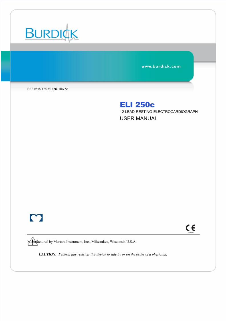
REF 9515-178-51-ENG Rev A1
ELI 250c12-LEAD RESTING ELECTROCARDIOGRAPH
USER MANUAL
Manufactured by Mortara Instrument, Inc., Milwaukee, Wisconsin U.S.A.
CAUTION: Federal law restricts this device to sale by or on the order of a physician.

7/23/2019 Burdick ELI 250 User Manual
http://slidepdf.com/reader/full/burdick-eli-250-user-manual 2/72
Copyright © 2013by Mortara Instrument, Inc.
7865 N. 86th StreetMilwaukee, Wisconsin 53224
This document contains confidential information that belongs to Mortara Instrument, Inc. No part of this documentmay be transmitted, reproduced, used, or disclosed outside of the receiving organization without the express written
consent of Mortara Instrument, Inc. Mortara and Burdick are registered trademarks of Mortara Instrument, Inc.
E-Scribe, ELI, and VERITAS are trademarks of Mortara Instrument, Inc. Cisco® is the registered trademark of
Cisco Systems, Inc. DICOM ® is the registered trademark of the National Electrical Manufacturers Association for
its standards publications relating to digital communications of medical information. V2.0

7/23/2019 Burdick ELI 250 User Manual
http://slidepdf.com/reader/full/burdick-eli-250-user-manual 3/72
TECHNICAL SUPPORT AND SERVICE
i
Headquarters
Mortara Instrument, Inc.7865 North 86th Street
Milwaukee, WI 53224
U.S.A.
Tel: 414.354.1600
Tel: 800.231.7437
Fax: 414.354.4760
Internet: http://www.burdick.com
European Union
Representative
Mortara Rangoni Europe, Srl
(European Headquarters)
Via Cimarosa 103/105
40033 Casalecchio di Reno (BO)
Italy
Tel: +39.051.298.7811
Fax: +39.051.613.3582
Service/Technical
Support Group
Mortara Instrument, Inc.
7865 North 86th Street
Milwaukee, WI 53224
U.S.A.
Tel: 414.354.1600
Service: 888.MORTARA
(888.667.8272)
Fax: 414.354.4760
E-mail: [email protected]
Sales Support/
Supplies & Accessories
Mortara Instrument, Inc.
7865 North 86th Street
Milwaukee, WI 53224
U.S.A.
Tel: 414.354.1600
Fax: 414.354.4760
Hospital Customers: [email protected]
Physician Practice: [email protected]
U.S. Distribution: [email protected]
Mortara Instrument GermanyBonifaciusring 15
45309 Essen
Germany
Tel: +49.201.18 55 69 70
Fax: +49.201.18 55 69 77
Mortara Instrument Netherlands
Postbus 324
5680 AH Best
Industrieweg 160b
5683 CG Best
Netherlands
Tel: +31.499.377310
Fax: +31.499.377908
Mortara Instrument Australia
PO Box 7568
Baulkham Hills NSW 2153
Unit 28, 9 Hoyle Avenue
Castle Hill NSW 2154
Australia
Tel: +61 2 8070 9303
Fax: +61 2 9899 9478
Mortara Dolby UK Ltd.
Units 11 & 12, Scion House
Stirling University Innovation Park
Stirling FK9 4NF
Scotland
Tel: +44.1786.444980
Fax: +44.1786.446630

7/23/2019 Burdick ELI 250 User Manual
http://slidepdf.com/reader/full/burdick-eli-250-user-manual 4/72
NOTICES
ii
Manufacturer’s Responsibili ty
Mortara Instrument, Inc. is responsible for the effects on safety and performance only if:
• Assembly operations, extensions, readjustments, modifications, or repairs are carried out only by Mortara-
authorized persons.
• The device is used in accordance with the instructions for use.
Respons ibility of the Customer
The user of this device is responsible for ensuring the implementation of a satisfactory maintenance schedule.
Failure to do so may cause undue failure and possible health hazards.
Equipment Identification
Burdick-branded equipment is identified by a serial and reference number on the back of the device. Care should betaken so that these numbers are not defaced.
Copyright and Trademark Notices
This document contains information that is protected by copyright. All rights are reserved. No part of this
document may be photocopied, reproduced, or translated to another language without prior written consent of
Mortara Instrument, Inc.
Other Important Information
The information in this document is subject to change without notice.
Mortara Instrument, Inc. makes no warranty of any kind with regard to this material including, but not limited to,implied warranties of merchantability and fitness for a particular purpose. Mortara Instrument, Inc. assumes no
responsibility for any errors or omissions that may appear in this document. Mortara Instrument, Inc. makes no
commitment to update or to keep current the information contained in this document.

7/23/2019 Burdick ELI 250 User Manual
http://slidepdf.com/reader/full/burdick-eli-250-user-manual 5/72
WARRANTY INFORMATION
iii
Your ortara Warranty
MORTARA INSTRUMENT, INC. (hereafter referred to as “Mortara”) warrants that components within Burdick-
branded products (hereafter referred to as “Product/s”) will be free from defects in workmanship and materials forthe number of years specified on documentation accompanying the product, or previously agreed to by the
purchaser and Mortara, or if not otherwise noted, for a period of twenty-four (24) months from the date of shipment.
Consumable, disposable or single use products such as, but not limited to, PAPER or ELECTRODES are warranted
to be free from defects in workmanship and materials for a period of 90 days from the date of shipment or the date
of first use, whichever is sooner.
Reusable product such as, but not limited to, BATTERIES, BLOOD PRESSURE CUFFS, BLOOD PRESSURE
HOSES, TRANSDUCER CABLES, Y-CABLES, PATIENT CABLES, LEAD WIRES, MAGNETIC STORAGE
MEDIUMS, CARRY CASES or MOUNTS, are warranted to be free from defects in workmanship and materials for
a period of 90 days. This warranty does not apply to damage to the Product/s caused by any or all of the following
circumstances or conditions:
a) Freight damage;
b) Parts and/or accessories of the Product/s not obtained from or approved by Mortara;
c) Misapplication, misuse, abuse, and/or failure to follow the Product/s instruction sheets and/or information
guides;
d) Accident; a disaster affecting the Product/s;
e) Alterations and/or modifications to the Product/s not authorized by Mortara;
f) Other events outside of Mortara’s reasonable control or not arising under normal operating conditions.
THE REMEDY UNDER THIS WARRANTY IS LIMITED TO THE REPAIR OR REPLACEMENT WITHOUTCHARGE FOR LABOR OR MATERIALS, OR ANY PRODUCT/S FOUND UPON EXAMINATION BY
MORTARA TO HAVE BEEN DEFECTIVE. This remedy shall be conditioned upon receipt of notice by Mortara
of any alleged defects promptly after discovery thereof within the warranty period. Mortara’s obligations under the
foregoing warranty will further be conditioned upon the assumption by the purchaser of the Product/s (i) of all
carrier charges with respect to any Product/s returned to Mortara’s principal place or any other place as specifically
designated by Mortara or an authorized distributor or representative of Mortara, and (ii) all risk of loss in transit. It
is expressly agreed that the liability of Mortara is limited and that Mortara does not function as an insurer. A
purchaser of a Product/s, by its acceptance and purchase thereof, acknowledges and agrees that Mortara is not liable
for loss, harm, or damage due directly or indirectly to an occurrence or consequence therefrom relating to the
Product/s. If Mortara should be found liable to anyone under any theory (except the expressed warranty set forth
herein) for loss, harm, or damage, the liability of Mortara shall be limited to the lesser of the actual loss, harm, or
damage, or the original purchase price of the Product/s when sold.

7/23/2019 Burdick ELI 250 User Manual
http://slidepdf.com/reader/full/burdick-eli-250-user-manual 6/72
WARRANTY INFORMATION
iv
EXCEPT AS SET FORTH HEREIN WITH RESPECT TO REIMBURSEMENT OF LABOR CHARGES, A
PURCHASER’S SOLE EXCLUSIVE REMEDY AGAINST MORTARA FOR CLAIMS RELATING TO THE
PRODUCT/S FOR ANY AND ALL LOSSES AND DAMAGES RESULTING FROM ANY CAUSE SHALL BE
THE REPAIR OR REPLACEMENT OF DEFECTIVE PRODUCT/S TO THE EXTENT THAT THE DEFECT IS NOTICED AND MORTARA IS NOTIFIED WITHIN THE WARRANTY PERIOD. IN NO EVENT,
INCLUDING THE CLAIM FOR NEGLIGENCE, SHALL MORTARA BE LIABLE FOR INCIDENTAL,
SPECIAL, OR CONSEQUENTIAL DAMAGES, OR FOR ANY OTHER LOSS, DAMAGE, OR EXPENSE OF
ANY KIND, INCLUDING LOSS OF PROFITS, WHETHER UNDER TORT, NEGLIGENCE OR STRICT
LIABILITY THEORIES OF LAW, OR OTHERWISE. THIS WARRANTY IS EXPRESSLY IN LIEU OF ANY
OTHER WARRANTIES, EXPRESS OR IMPLIED, INCLUDING, BUT NOT LIMITED TO THE IMPLIED
WARRANTY OF MERCHANTABILITY AND THE WARRANTY OF FITNESS FOR A PARTICULAR
PURPOSE.

7/23/2019 Burdick ELI 250 User Manual
http://slidepdf.com/reader/full/burdick-eli-250-user-manual 7/72
USER SAFETY INFORMATION
v
Warning: Means there is the possibility of personal injury to you or others.
Caution: Means there is the possibility of damage to the device.
Note: Provides information to further assist in the use of the device.
Warning(s)
• This manual gives important information about the use and safety of this device. Deviating from operating
procedures, misuse or misapplication of the device, or ignoring specifications and recommendations could
result in increased risk of harm to users, patients and bystanders, or damage to the device.
• Device captures and presents data reflecting a patient’s physiological condition that when reviewed by a trained
physician or clinician can be useful in determining a diagnosis; however, the data should not be used as a sole
means for determining a patient’s diagnosis.
• Users are expected to be licensed clinical professionals knowledgeable about medical procedures and patient
care, and adequately trained in the use of this device. Before attempting to use this device for clinical
applications, the operator must read and understand the contents of the user manual and other accompanying
documents. Inadequate knowledge or training could result in increased risk of harm to users, patients and
bystanders, or damage to the device. Contact technical service for additional training options.
• To ensure that electrical safety is maintained during operation from AC (~) power, the device must be plugged
into a hospital-grade outlet.
• To maintain designed operator and patient safety, peripheral equipment and accessories used that can come in
direct patient contact must be in compliance with UL 60601-1, IEC 60601-1, and IEC 60601-2-25. Only use
parts and accessories supplied with the device and available through Mortara.
• Patient cables intended for use with the device include series resistance (9 Kohm minimum) in each lead for
defibrillation protection. Patient cables should be checked for cracks or breakage prior to use.
• Conductive parts of the patient cable, electrodes, and associated connections of type CF applied parts, including
the neutral conductor of the patient cable and electrodes, should not come into contact with other conductive
parts including earth ground.
• ECG electrodes could cause skin irritation; patients should be examined for signs of irritation or inflammation.
• To avoid the possibility of serious injury or death during patient defibrillation, do not come into contact with
device or patient cables. Additionally, proper placement of defibrillator paddles in relation to the electrodes is
required to minimize harm to the patient. This device was designed to use the electrodes specified in this
manual. Proper clinical procedure must be employed to prep the electrode sites and to monitor the patient for
excessive skin irritation, inflammation, or other adverse reactions. Electrodes are intended for short-term use
and should be removed from the patient promptly following testing.

7/23/2019 Burdick ELI 250 User Manual
http://slidepdf.com/reader/full/burdick-eli-250-user-manual 8/72
USER SAFETY INFORMATION
vi
• To avoid potential for spread of disease or infection, single-use disposable components (e.g., electrodes) must
not be reused. To maintain safety and effectiveness, electrodes must not be used beyond their expiration date.
• To ensure the safety of both the patient and the device, 1.5 meters (5’) of open area should surround the patient.
• A possible explosion hazard exists. Do not use the device in the presence of a flammable anesthetic mixture.
• Where the integrity of external protective earth conductor arrangement is in doubt, the device shall be operated
from its internal electrical power source.
• All signal input and output (I/O) connectors are intended for connection of only those devices complying with
IEC 60601-1, or other IEC standards (e.g., IEC 60950) as appropriate to the device. Connecting additional
devices to the device may increase chassis and/or patient leakage currents. To maintain operator and patient
safety, consideration should be given to the requirements of IEC 60601-1-1, and leakage currents should be
measured to confirm no electric shock hazard exists.
• To improve immunity to potential interfering electromagnetic signals, shielded cabling is recommended whenconnecting the device to a network.
• To maintain operator and patient safety, equipment connected to the same network as the device must meet the
requirements of IEC 60950 or IEC 60601-1.
• To prevent electric shock due to unequal ground potentials that may exist between points of a distributed
network system or fault conditions in external network connected equipment, network cable shielding (where
used) must be connected to protective earth ground appropriate to the area where the device is used.
• The device has not been designed for use with high-frequency (HF) surgical equipment and does not provide a
protective means against hazards to the patient.
• The quality of the signal produced by the device may be adversely affected by the use of other medicalequipment, including but not limited to defibrillators and ultrasound machines.
• For proper operation and the safety of users or patients and bystanders, equipment and accessories must be
connected only as described in this manual. Do not connect a telephone line cable to the LAN connector.
• Some Burdick electrocardiographs can be equipped with a wireless LAN (WLAN) module for transmitting
ECG records. Device labeling and the presence of an antenna port will indicate if your device is equipped with
such a module. If so equipped, the following notices apply:
• The WLAN identification can be found on a label on the bottom of the device.
• Quatech, Inc. Model WLNG-AN-DP101: 2400 MHz
(model subject to change without notice)
• Use of the WLAN module may interfere with other equipment operating in the vicinity. Check with local
authorities or spectrum management officials in your facility to determine if restrictions apply to the use of this
feature in your area.
• Do not transmit via the WLAN module with a missing or damaged antenna. Replace a damaged antenna
immediately.

7/23/2019 Burdick ELI 250 User Manual
http://slidepdf.com/reader/full/burdick-eli-250-user-manual 9/72
USER SAFETY INFORMATION
vii
• Use only the antenna supplied for use with this device. Unauthorized antennas, modifications, or attachments
could damage the wireless module and may contravene local RF emission regulations or invalidate type
approval.
• To ensure compliance with current regulations limiting both maximum RF output power and human exposure
to radio frequency radiation, a separation distance of at least 20 cm must be maintained between the device's
antenna and the head and body of the user and any nearby persons at all times. To help prevent degradation of
RF signal and to avoid excess RF energy absorption, do not touch the antenna during data transmission.
• The WLAN modules comply with applicable RF safety standards including standards and recommendations for
the protection of public exposure to RF electromagnetic energy that have been established by governmental
bodies and other qualified organizations, such as the following:
• Federal Communications Commission (FCC)
• Directives of the European Community
• Directorate General V in Matters of Radio Frequency Electromagnetic Energy
Caution(s)
• To prevent possible damage to the keyboard, do not use sharp or hard objects to depress keys, only
use fingertips.
• Do not attempt to clean the device or patient cables by submersing into a liquid, autoclaving, or steam cleaning
as this may damage equipment or reduce its usable life. Wipe the exterior surfaces with a warm water and mild
detergent solution and then dry with a clean cloth. Use of unspecified cleaning/disinfecting agents, failure to
follow recommended procedures, or contact with unspecified materials could result in increased risk of harm to
users, patients and bystanders, or damage to the device.
• No user-serviceable parts inside. Screw removal by qualified service personnel only. Damaged or suspected
inoperative equipment must be immediately removed from use and must be checked/repaired by qualified
service personnel prior to continued use.
• The rechargeable internal battery is a sealed lead-acid type and it is totally maintenance free. If the battery
appears to become defective, refer to Technical Service Department.
• Do not pull or stretch patient cables as this could result in mechanical and/or electrical failures. Patient cables
should be stored after forming them into a loose loop.
• No calibration or special equipments are needed for the proper operation or maintenance of the device.
● When necessary, dispose of the device, its components and accessories (e.g., batteries, cables, electrodes),
and/or packing materials in accordance with local regulations.

7/23/2019 Burdick ELI 250 User Manual
http://slidepdf.com/reader/full/burdick-eli-250-user-manual 10/72
USER SAFETY INFORMATION
viii
Note(s)
• Patient movements may generate excessive noise that may affect the quality of the ECG traces and the proper
analysis performed by the device.
• Proper patient preparation is important to proper application of ECG electrodes and operation of the device.
• The algorithm detecting electrode misplacements is based on normal physiology and ECG lead order, and tries
to identify the most likely switch; however, it is advisable to check the other electrode positions in the same
group (limb or chest).
• There is no known safety hazard if other equipment, such as pacemakers or other stimulators, is used
simultaneously with the device; however, disturbance to the signal may occur.
• A square wave presentation on the display while using the WAM may be due to the WAM being turned off,
having no battery, not being paired correctly, operating out of range, or due to a calibration error. Review the
LED indicator on the WAM to ensure the unit is turned on, has proper battery level, is paired correctly, and is
within recommended proximity of the electrocardiograph, or power cycle the WAM to re-calibrate.
• A square wave presentation on the display while using the AM12 may be due to improper auto-calibration.
Power cycle the AM12 or the electrocardiograph.
• If electrode is not properly connected to the patient, or one or more of the patient cable lead wires is damaged,
display will indicate a lead fault for the lead(s) where the condition is present and if the signal is being printed,
the respective lead(s) will print out as a square wave.
• As defined by IEC 60601-1 and IEC 60601-2-25, the device is classified as follows:
• Class I equipment or internally powered.
• Type CF defibrillation-proof applied parts.• Ordinary equipment.
• Equipment not suitable for use in the presence of a flammable anesthetic mixture.
• Continuous operation.
NOTE: From a safety perspective, per IEC 60601-1 and derivative standards/norms, this device is
declared to be “Class I” and uses a three-prong inlet to ensure an earth connection is made along with
mains. The ground terminal on the mains inlet is the only protective earth point in the device. Exposed
metal accessible during normal operation is double insulated from mains. Internal connections to earth
ground are functional earth.

7/23/2019 Burdick ELI 250 User Manual
http://slidepdf.com/reader/full/burdick-eli-250-user-manual 11/72
USER SAFETY INFORMATION
ix
• This device is intended to be used in a hospital or doctor’s office setting, and should be used and stored
according to the environmental conditions specified below:
Operating temperature: +10° to +40°C (+50° to +104°F)Operating humidity: 10% to 95% RH, non-condensing
Storage temperature: -40° to +70°C (-40° to +158°F)
Storage humidity: 10% to 95% RH, non-condensing
Atmospheric pressure: 500 hPa to 1060 hPa
• WAM™ (wireless acquisition module) must be paired to electrocardiograph before operation.
• Device must be configured at the factory for use with the WAM.
• After operating the device using battery power, always reconnect the power cord. This ensures that the
batteries will be automatically recharged for the next time you use the device.
• The device is UL classified.
WITH RESPECT TO ELECTRIC SHOCK, FIRE AND MECHANICALHAZARDS ONLY IN ACCORDANCE WITH UL60601-1, IEC60601-1,CAN/CSA C22.2 No. 601.1, IEC 60601-1-1, CAN/CSA C22.2 No. 60601-1-1-02, IEC60601-2-25 AND CAN/CSA C22.2 No. 601.2.25-94.
• The device is a member of the ELI 2xx Series 2 electrocardiograph family.
Wireless Data Transmission
• Some Burdick electrocardiographs can be equipped with an optional wireless data transmission module(WLAN). Both these technologies use radios to transmit data to a Burdick receiving application. Due to the
nature of radio transmissions, it’s possible that, due to the characteristics of the environment where the device
is located, some other RF sources may interfere with the transmission generated by the device. Mortara has
tested the coexistence of the device with other devices that can interfere such as devices using WLAN,
Bluetooth radio, and/or cell phones. Although the current technology allows a very successful rate of
transmission, it’s possible that in some rare occurrences, the system may not perform at its best resulting in a
“failed transmission.” When this occurs, patient data will not be erased from the device nor stored in the
receiving application, ensuring that partial or corrupted data are not made available to the receiving station. If
the failure mode persists the user should move to a position where the RF signals may propagate better and
allow successful transmissions.
7/23/2019 Burdick ELI 250 User Manual
http://slidepdf.com/reader/full/burdick-eli-250-user-manual 12/72
USER SAFETY INFORMATION
x
WLAN Option
• Wireless options transmit at 2.4 GHz. Other nearby wireless devices may cause interference. If possible, move
or turn off other devices to minimize potential interference.
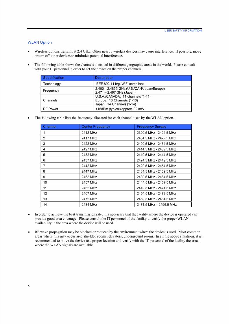
• The following table shows the channels allocated in different geographic areas in the world. Please consult
with your IT personnel in order to set the device on the proper channels.
Specification Description
Technology IEEE 802.11 b/g, WiFi compliant
Frequency2.400 – 2.4835 GHz (U.S./CAN/Japan/Europe)2.471 – 2.497 GHz (Japan)
ChannelsU.S.A./CANADA: 11 channels (1-11)Europe: 13 Channels (1-13)Japan: 14 Channels (1-14)
RF Power +15dBm (typical) approx. 32 mW
• The following table lists the frequency allocated for each channel used by the WLAN option.
Channel Center Frequency Frequency Spread
1 2412 MHz 2399.5 MHz - 2424.5 MHz
2 2417 MHz 2404.5 MHz - 2429.5 MHz
3 2422 MHz 2409.5 MHz - 2434.5 MHz
4 2427 MHz 2414.5 MHz - 2439.5 MHz
5 2432 MHz 2419.5 MHz - 2444.5 MHz
6 2437 MHz 2424.5 MHz - 2449.5 MHz
7 2442 MHz 2429.5 MHz - 2454.5 MHz
8 2447 MHz 2434.5 MHz - 2459.5 MHz
9 2452 MHz 2439.5 MHz - 2464.5 MHz
10 2457 MHz 2444.5 MHz - 2469.5 MHz
11 2462 MHz 2449.5 MHz - 2474.5 MHz
12 2467 MHz 2454.5 MHz - 2479.5 MHz
13 2472 MHz 2459.5 MHz - 2484.5 MHz
14 2484 MHz 2471.5 MHz – 2496.5 MHz
• In order to achieve the best transmission rate, it is necessary that the facility where the device is operated can
provide good area coverage. Please consult the IT personnel of the facility to verify the proper WLAN
availability in the area where the device will be used.
• RF wave propagation may be blocked or reduced by the environment where the device is used. Most common
areas where this may occur are: shielded rooms, elevators, underground rooms. In all the above situations, it is
recommended to move the device to a proper location and verify with the IT personnel of the facility the areas
where the WLAN signals are available.
7/23/2019 Burdick ELI 250 User Manual
http://slidepdf.com/reader/full/burdick-eli-250-user-manual 13/72
EQUIPMENT SYMBOLS AND MARKINGS
xi
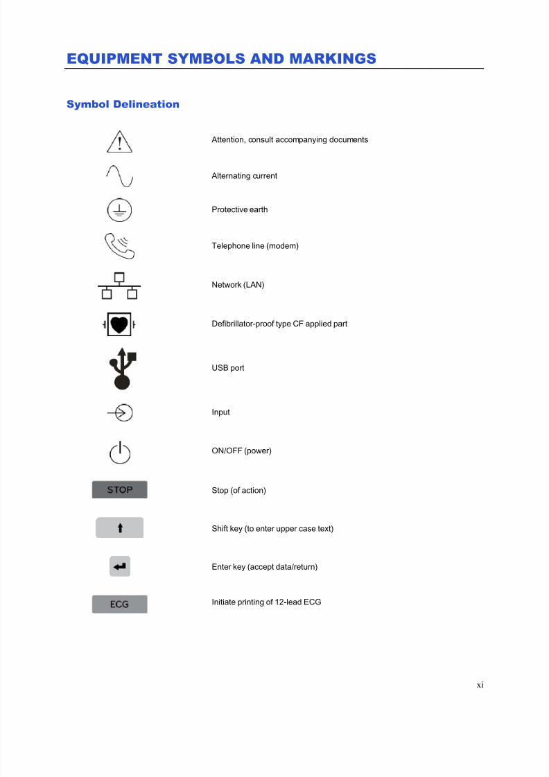
Symbol Delineation
Attention, consult accompanying documents
Alternating current
Protective earth
Telephone line (modem)
Network (LAN)
Defibrillator-proof type CF applied part
USB port
Input
ON/OFF (power)
Stop (of action)
Shift key (to enter upper case text)
Enter key (accept data/return)
Initiate printing of 12-lead ECG
7/23/2019 Burdick ELI 250 User Manual
http://slidepdf.com/reader/full/burdick-eli-250-user-manual 14/72
EQUIPMENT SYMBOLS AND MARKINGS
xii
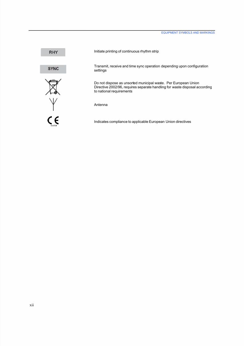
Initiate printing of continuous rhythm strip
Transmit, receive and time sync operation depending upon configurationsettings
Do not dispose as unsorted municipal waste. Per European UnionDirective 2002/96, requires separate handling for waste disposal accordingto national requirements
Antenna
Indicates compliance to applicable European Union directives

7/23/2019 Burdick ELI 250 User Manual
http://slidepdf.com/reader/full/burdick-eli-250-user-manual 15/72
GENERAL CARE
xiii
Precautions
• Turn off the device before inspecting or cleaning.
• Do not immerse the device in water.• Do not use organic solvents, ammonia-based solutions, or abrasive cleaning agents which may damage
equipment surfaces.
Inspection
Inspect your equipment daily prior to operation. If you notice anything that requires repair, contact an authorized
service person to make the repairs.
• Verify that all cords and connectors are securely seated.
• Check the case and chassis for any visible damage.
• Inspect cords and connectors for any visible damage.
• Inspect keys and controls for proper function and appearance.
Cleaning Exterior Surfaces and Patient Cable
1. Remove cables and lead wires from device before cleaning.
2. For general cleaning of cables and lead wires, use a soft, lint-free cloth lightly moistened with a mild soap
and water solution. Wipe and air dry.
3. For disinfecting the cables and lead wires, wipe exterior with a soft, lint-free cloth using a solution of
Sodium Hypochlorite (10% household bleach and water solution) minimum 1:500 dilution (minimum 100
ppm free chlorine) and maximum 1:10 dilution as recommended by the APIC Guidelines for Selection and
Use of Disinfectants.
4. Use caution with excess liquid as contact with metal parts may cause corrosion.
5. Do not immerse cable ends or lead wires; immersion can cause metal corrosion.
6. Do not use excessive drying techniques such as forced heat.
WARNING: Prevent liquid from penetrating the device and do not attempt to clean/disinfect the
device or patient cables by submerging into a liquid, autoclaving, or steam cleaning. Never expose cables
to strong ultra-violet radiation. Do not sterilize the device or ECG lead wires with Ethylene Oxide (EtO)
gas.
Cleaning the Device
Disconnect the power source. Clean the exterior surface of the device with a damp, soft, lint-free cloth using a
solution of mild detergent diluted in water. After washing, thoroughly dry off the device with a clean, soft cloth or
paper towel.

7/23/2019 Burdick ELI 250 User Manual
http://slidepdf.com/reader/full/burdick-eli-250-user-manual 16/72
GENERAL CARE
xiv
Sterilization
EtO sterilization is not recommended but may be required for cables and lead wires. Frequent sterilization will
reduce the useful life of cables and lead wires. If required, sterilize with ethylene oxide gas (EtO) at a maximumtemperature of 50°C/122°F. After EtO sterilization, follow the recommendations from the sterilizer manufacturer
for required aeration.
Cautions
Improper cleaning products and processes can damage the device, produce brittle lead wires and cables, corrode the
metal, and void the warranty. Use care and proper procedure whenever cleaning or maintaining the device.

7/23/2019 Burdick ELI 250 User Manual
http://slidepdf.com/reader/full/burdick-eli-250-user-manual 17/72
ELECTROMAGNETIC COMPATIBILITY (EMC)
xv
Electromagnetic compatibility with surrounding devices should be assessed when using the device.
An electronic device can either generate or receive electromagnetic interference. Testing for electromagnetic
compatibility (EMC) has been performed on the device according to the international standard for EMC for medical
devices (IEC 60601-1-2). This IEC standard has been adopted in Europe as the European Norm (EN 60601-1-2).
The device should not be used adjacent to, or stacked on top of other equipment. If the device must be used
adjacent to or stacked on top of other equipment, verify that the device operates in an acceptable manner in the
configuration in which it will be used.
Fixed, portable, and mobile radio frequency communications equipment can affect the performance of medical
equipment. See Table X-4 for recommended separation distances between the radio equipment and the device.
The use of accessories, transducers, and cables other than those specified by Mortara Instrument may result in
increased emissions or decreased immunity of the equipment.
7/23/2019 Burdick ELI 250 User Manual
http://slidepdf.com/reader/full/burdick-eli-250-user-manual 18/72
ELECTROMAGNETIC COMPATIBILITY (EMC)
xvi
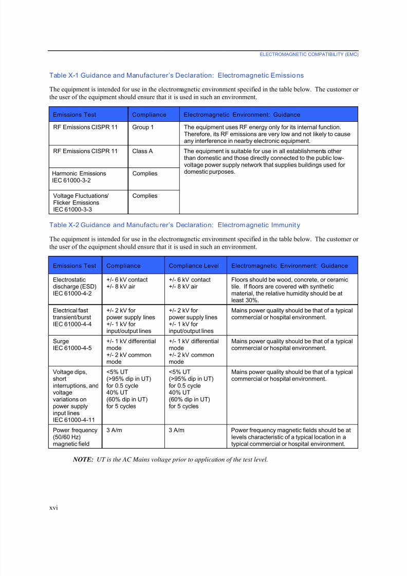
Table X-1 Guidance and Manufacturer’s Declaration: Electromagnetic Emissions
The equipment is intended for use in the electromagnetic environment specified in the table below. The customer or
the user of the equipment should ensure that it is used in such an environment.
Emissions Test Compliance Electromagnetic Environment: Guidance
RF Emissions CISPR 11 Group 1 The equipment uses RF energy only for its internal function.Therefore, its RF emissions are very low and not likely to causeany interference in nearby electronic equipment.
RF Emissions CISPR 11 Class A The equipment is suitable for use in all establishments otherthan domestic and those directly connected to the public low-voltage power supply network that supplies buildings used fordomestic purposes.Harmonic Emissions
IEC 61000-3-2Complies
Voltage Fluctuations/
Flicker EmissionsIEC 61000-3-3
Complies
Table X-2 Guidance and Manufacturer’s Declaration: Electromagnetic Immunity
The equipment is intended for use in the electromagnetic environment specified in the table below. The customer or
the user of the equipment should ensure that it is used in such an environment.
Emissions Test Compliance Compliance Level Electromagnetic Environment: Guidance
Electrostaticdischarge (ESD)IEC 61000-4-2
+/- 6 kV contact+/- 8 kV air
+/- 6 kV contact+/- 8 kV air
Floors should be wood, concrete, or ceramictile. If floors are covered with syntheticmaterial, the relative humidity should be at
least 30%.Electrical fasttransient/burstIEC 61000-4-4
+/- 2 kV forpower supply lines+/- 1 kV forinput/output lines
+/- 2 kV forpower supply lines+/- 1 kV forinput/output lines
Mains power quality should be that of a typicalcommercial or hospital environment.
SurgeIEC 61000-4-5
+/- 1 kV differentialmode+/- 2 kV commonmode
+/- 1 kV differentialmode+/- 2 kV commonmode
Mains power quality should be that of a typicalcommercial or hospital environment.
Voltage dips,shortinterruptions, andvoltagevariations onpower supplyinput linesIEC 61000-4-11
<5% UT(>95% dip in UT)for 0.5 cycle40% UT(60% dip in UT)for 5 cycles
<5% UT(>95% dip in UT)for 0.5 cycle40% UT(60% dip in UT)for 5 cycles
Mains power quality should be that of a typicalcommercial or hospital environment.
Power frequency(50/60 Hz)magnetic field
3 A/m 3 A/m Power frequency magnetic fields should be atlevels characteristic of a typical location in atypical commercial or hospital environment.
NOTE: UT is the AC Mains voltage prior to application of the test level.
7/23/2019 Burdick ELI 250 User Manual
http://slidepdf.com/reader/full/burdick-eli-250-user-manual 19/72
ELECTROMAGNETIC COMPATIBILITY (EMC)
xvii
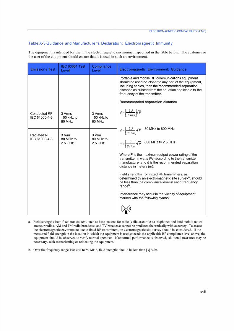
Table X-3 Guidance and Manufacturer’s Declaration: Electromagnetic Immunity
The equipment is intended for use in the electromagnetic environment specified in the table below. The customer or
the user of the equipment should ensure that it is used in such an environment.
Emissions Test IEC 60601 Test
Level
Compliance
Level Electromagnetic Environment: Guidance
Conducted RFIEC 61000-4-6
3 Vrms 150 kHz to80 MHz
3 Vrms 150 kHz to80 MHz
Portable and mobile RF communications equipmentshould be used no closer to any part of the equipment,including cables, than the recommended separationdistance calculated from the equation applicable to thefrequency of the transmitter.
Recommended separation distance
P
Vrms
d ⎥
⎦
⎤⎢
⎣
⎡=
3
5.3
PmV
d ⎥⎦
⎤⎢⎣
⎡=
/3
5.3 80 MHz to 800 MHz
PmV
d ⎥⎦
⎤⎢⎣
⎡=
/3
7 800 MHz to 2.5 GHz
Where P is the maximum output power rating of thetransmitter in watts (W) according to the transmittermanufacturer and d is the recommended separationdistance in meters (m).
Field strengths from fixed RF transmitters, asdetermined by an electromagnetic site surveya, shouldbe less than the compliance level in each frequencyrangeb.
Interference may occur in the vicinity of equipmentmarked with the following symbol:
Radiated RFIEC 61000-4-3
3 V/m
80 MHz to2.5 GHz
3 V/m
80 MHz to2.5 GHz
a. Field strengths from fixed transmitters, such as base stations for radio (cellular/cordless) telephones and land mobile radios,
amateur radios, AM and FM radio broadcast, and TV broadcast cannot be predicted theoretically with accuracy. To assess
the electromagnetic environment due to fixed RF transmitters, an electromagnetic site survey should be considered. If the
measured field strength in the location in which the equipment is used exceeds the applicable RF compliance level above, the
equipment should be observed to verify normal operation. If abnormal performance is observed, additional measures may be
necessary, such as reorienting or relocating the equipment.
b. Over the frequency range 150 kHz to 80 MHz, field strengths should be less than [3] V/m.
7/23/2019 Burdick ELI 250 User Manual
http://slidepdf.com/reader/full/burdick-eli-250-user-manual 20/72
ELECTROMAGNETIC COMPATIBILITY (EMC)
xviii
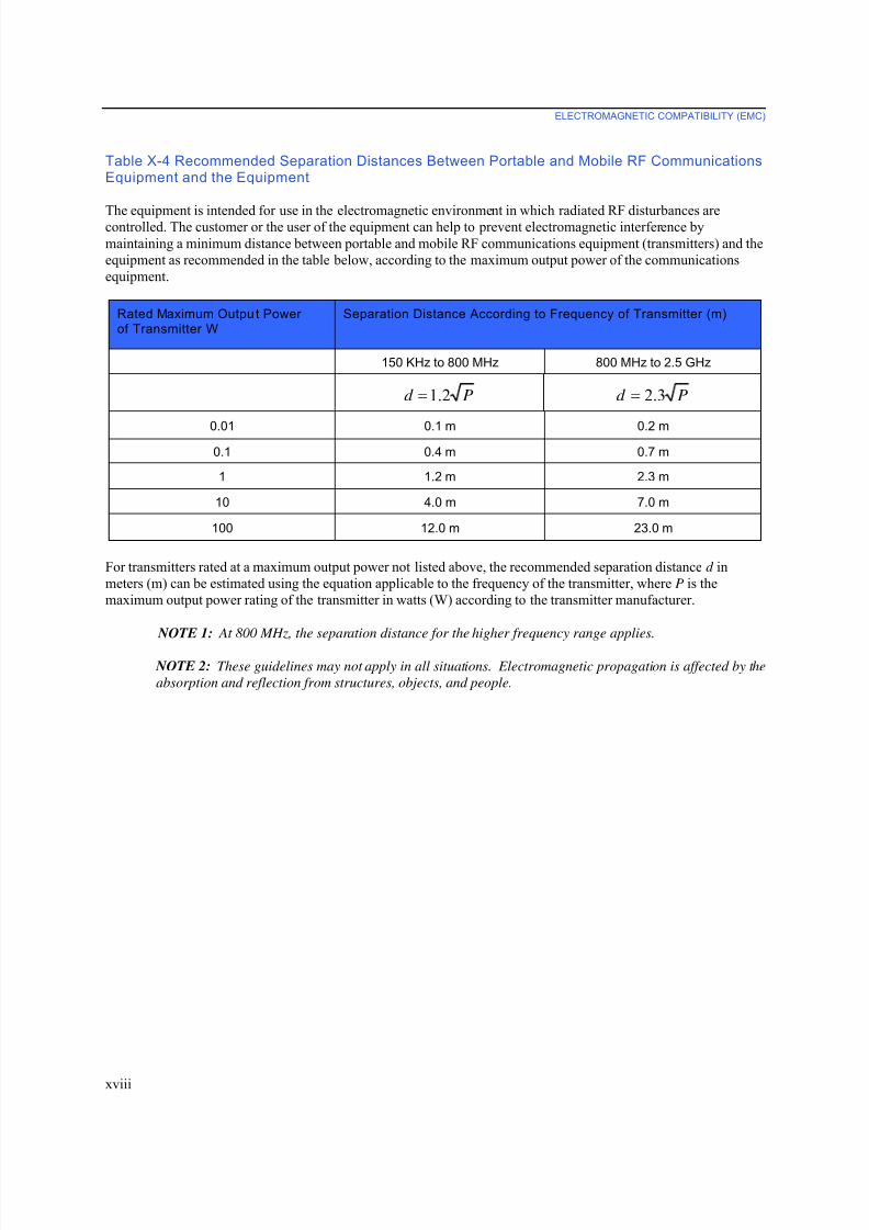
Table X-4 Recommended Separation Distances Between Portable and Mobile RF CommunicationsEquipment and the Equipment
The equipment is intended for use in the electromagnetic environment in which radiated RF disturbances arecontrolled. The customer or the user of the equipment can help to prevent electromagnetic interference by
maintaining a minimum distance between portable and mobile RF communications equipment (transmitters) and the
equipment as recommended in the table below, according to the maximum output power of the communications
equipment.
Rated Maximum Output Powerof Transmitter W
Separation Distance According to Frequency of Transmitter (m)
150 KHz to 800 MHz 800 MHz to 2.5 GHz
Pd 2.1= Pd 3.2=
0.01 0.1 m 0.2 m
0.1 0.4 m 0.7 m
1 1.2 m 2.3 m
10 4.0 m 7.0 m
100 12.0 m 23.0 m
For transmitters rated at a maximum output power not listed above, the recommended separation distance d in
meters (m) can be estimated using the equation applicable to the frequency of the transmitter, where P is the
maximum output power rating of the transmitter in watts (W) according to the transmitter manufacturer.
NOTE 1: At 800 MHz, the separation distance for the higher frequency range applies.
NOTE 2: These guidelines may not apply in all situations. Electromagnetic propagation is affected by the
absorption and reflection from structures, objects, and people.
7/23/2019 Burdick ELI 250 User Manual
http://slidepdf.com/reader/full/burdick-eli-250-user-manual 21/72
TABLE OF CONTENTS
xix
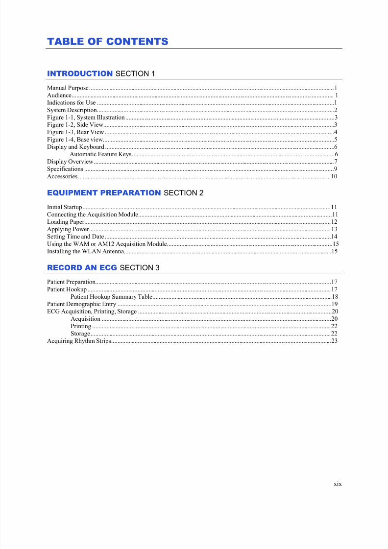
INTRODUCTION SECTION 1
Manual Purpose ............................................................................................................................................................. 1
Audience ........................................................................................................................................................................ 1Indications for Use ........................................................................................................................................................ 1
System Description ........................................................................................................................................................ 2
Figure 1-1, System Illustration ...................................................................................................................................... 3
Figure 1-2, Side View.................................................................................................................................................... 3
Figure 1-3, Rear View ................................................................................................................................................... 4
Figure 1-4, Base view .................................................................................................................................................... 5
Display and Keyboard ................................................................................................................................................... 6
Automatic Feature Keys .................................................................................................................................. 6
Display Overview .......................................................................................................................................................... 7
Specifications ................................................................................................................................................................ 9
Accessories .................................................................................................................................................................. 10
EQUIPMENT PREPARATION SECTION 2 Initial Startup ............................................................................................................................................................... 11
Connecting the Acquisition Module ............................................................................................................................ 11
Loading Paper .............................................................................................................................................................. 12
Applying Power ........................................................................................................................................................... 13
Setting Time and Date ................................................................................................................................................. 14
Using the WAM or AM12 Acquisition Module .......................................................................................................... 15
Installing the WLAN Antenna ..................................................................................................................................... 15
RECORD AN ECG SECTION 3
Patient Preparation ....................................................................................................................................................... 17
Patient Hookup ............................................................................................................................................................ 17Patient Hookup Summary Table ................................................................................................................... 18
Patient Demographic Entry ......................................................................................................................................... 19
ECG Acquisition, Printing, Storage ............................................................................................................................ 20
Acquisition ................................................................................................................................................... 20
Printing ......................................................................................................................................................... 22
Storage .......................................................................................................................................................... 22
Acquiring Rhythm Strips ............................................................................................................................................. 23
7/23/2019 Burdick ELI 250 User Manual
http://slidepdf.com/reader/full/burdick-eli-250-user-manual 22/72
TABLE OF CONTENTS
xx
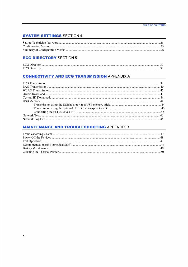
SYSTEM SETTINGS SECTION 4
Setting Technician Password ....................................................................................................................................... 25
Configuration Menus ................................................................................................................................................... 25Summary of Configuration Menus .............................................................................................................................. 26
ECG DIRECTORY SECTION 5
ECG Directory ............................................................................................................................................................. 37
ECG Order List............................................................................................................................................................ 38
CONNECTIVITY AND ECG TRANSMISSION APPENDIX A
ECG Transmission ....................................................................................................................................................... 39
LAN Transmission ...................................................................................................................................................... 40
WLAN Transmission ................................................................................................................................................... 42
Orders Download ........................................................................................................................................................ 43Custom ID Download .................................................................................................................................................. 44
USB Memory ............................................................................................................................................................... 44
Transmission using the USB host port to a USB memory stick .................................................................... 44
Transmission using the optional USBD (device) port to a PC ...................................................................... 45
Connecting the ELI 250c to a PC .................................................................................................................. 45
Network Test ............................................................................................................................................................... 46
Network Log File ........................................................................................................................................................ 46
MAINTENANCE AND TROUBLESHOOTING APPENDIX B
Troubleshooting Charts ............................................................................................................................................... 47
Power Off the Device .................................................................................................................................................. 49
Test Operation ............................................................................................................................................................. 49Recommendations to Biomedical Staff ....................................................................................................................... 49
Battery Maintenance .................................................................................................................................................... 49
Cleaning the Thermal Printer ...................................................................................................................................... 50

7/23/2019 Burdick ELI 250 User Manual
http://slidepdf.com/reader/full/burdick-eli-250-user-manual 23/72
INTRODUCTIONSECTION 1
1
Manual Purpose
This manual is intended to provide the user with information about:
• Using and understanding the ELI 250c electrocardiograph, the function and feature keys, and the displayscreen.
• Preparing the device for use. (Section 2)
• Acquiring, printing, and storing an ECG. (Section 3)
• System settings. (Section 4)
• Connectivity and transmitting ECGs. (Appendix A)
• Maintenance and troubleshooting. (Appendix B)
NOTE: This manual may contain screen shots. Any screen shots are provided for reference only and are
not intended to convey actual operating techniques. Consult the actual screen in the host language for
specific wording.
Audience
This manual is written for clinical professionals. They are expected to have working knowledge of medical procedures and terminology as required for monitoring cardiac patients.
Indications for Use
• Device is indicated for use to acquire, analyze, display, and print electrocardiograms.
• Device is indicated for use to provide interpretation of the data for consideration by a physician.
• Device is indicated for use in a clinical setting, by a physician or by trained personnel who are acting on theorders of a licensed physician. It is not intended as a sole means of diagnosis.
• The interpretations of ECG offered by the device are only significant when used in conjunction with a
physician over-read as well as consideration of all other relevant patient data.
• Device is indicated for use on adult and pediatric populations.
• The device is not intended to be used as a vital signs physiological monitor.
7/23/2019 Burdick ELI 250 User Manual
http://slidepdf.com/reader/full/burdick-eli-250-user-manual 24/72
SECTION 1
2
System Description
The device is a 12-lead diagnostic electrocardiograph used for acquiring, viewing, and printing adult and pediatric
12-lead ECG data. The device is equipped with the VERITAS™ resting ECG interpretation algorithm with age and
gender specific criteria. The VERITAS algorithm can provide an over-reading physician with a silent secondopinion through diagnostic statements output on the ECG report. For additional information on the VERITAS
algorithm, please refer to the Physician’s Guide Adult and Pediatric user manual. (See Accessories.)
The device can be configured with expanded memory, bidirectional connectivity, and DICOM® protocol support,
and operates on battery or line power.
Supported print formats for the ELI 250c include: standard or Cabrera 3+1, 3+3, 6, 6+6, or 12 channel in automatic
mode; 3, 6, or 12 channel rhythm strip printing.
With either model, during rhythm strip printing the user can toggle between the various channels (default leads, limb
and chest leads, etc.) to print by selecting F2 (Leads). To suspend a rhythm strip print, press F6 (Stby); press
F6 (Cont) to resume. Press STOP at any time to end rhythm strip printing.
The device includes:
• Acquisition module with lead wire set
• Hospital-grade power cord
• Antenna (with WLAN)
• 1 pack paper
• 1 package of electrodes
• Physicians Guide Adult & Pediatric (with interpretation feature)
• User manual CD
• Accessory starter kit
7/23/2019 Burdick ELI 250 User Manual
http://slidepdf.com/reader/full/burdick-eli-250-user-manual 25/72
SECTION 1
3
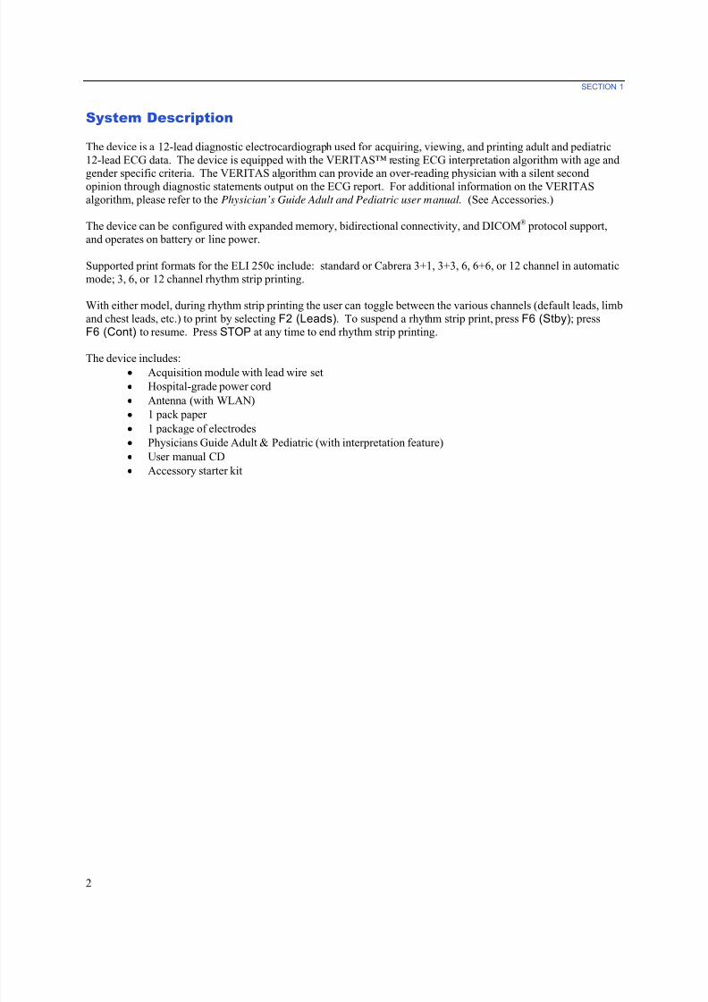
System Illustration
Figure 1-1
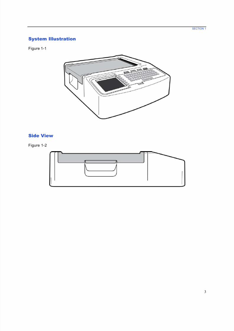
Side View
Figure 1-2
7/23/2019 Burdick ELI 250 User Manual
http://slidepdf.com/reader/full/burdick-eli-250-user-manual 26/72
SECTION 1
4
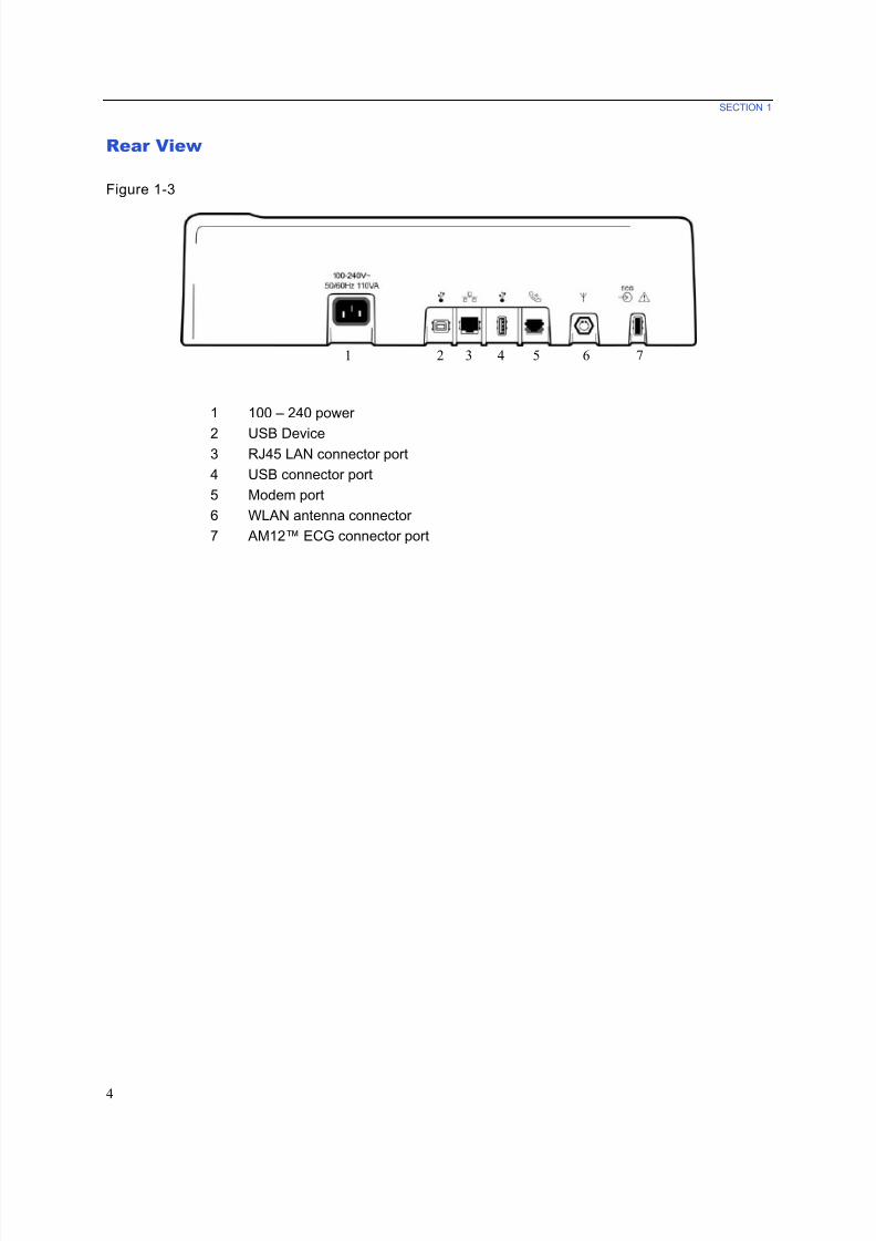
Rear View
Figure 1-3
1 2 3 4 5 6 7
1 100 – 240 power
2 USB Device3 RJ45 LAN connector port
4 USB connector port
5 Modem port
6 WLAN antenna connector
7 AM12™ ECG connector port
7/23/2019 Burdick ELI 250 User Manual
http://slidepdf.com/reader/full/burdick-eli-250-user-manual 27/72
SECTION 1
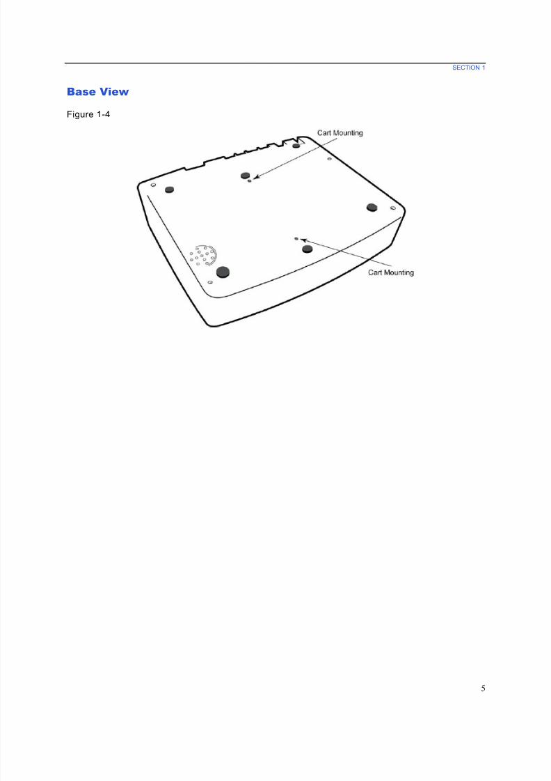
5
Base View
Figure 1-4
7/23/2019 Burdick ELI 250 User Manual
http://slidepdf.com/reader/full/burdick-eli-250-user-manual 28/72
SECTION 1
6
Display and Keyboard
Figure 1-5
Automat ic Feature Keys
Automatic feature keys are used as a one-touch operation for:
ECG Acquisition
Rhythm Printing
Transmit and/or Download Order List; Time Sync
Stop
7/23/2019 Burdick ELI 250 User Manual
http://slidepdf.com/reader/full/burdick-eli-250-user-manual 29/72
SECTION 1
7
Display Overview
The device features a ¼ VGA 320 x 240 pixels LCD color display for valuable preview of ECG waveform, function
key labels, and other parameters as explained below. During ECG acquisition, notification messages will also
appear on the display. (See Section 3, ECG Acquisition, Printing, Storage.)
Figure 1-6
Heart Rate (HR):
When a patient is connected to the electrocardiograph, his/her HR is displayed in real time. The HR is the average
ventricular rate measured over an average of the patient’s last five beats.
Speed:
Use F3 (Speed) to select display speed or rhythm printout speed: 5 mm/s, 10 mm/s, 25 mm/s, or 50mm/s. Paper
speed is printed at the bottom right corner of the ECG printout.
Gain:
Use F4 (Gain) to select waveform amplitude for display and printout: 5 mm/mV, 10 mm/mV, or 20 mm/mV. Gain
is printed at the bottom right corner of the ECG printout.
Filter:
Use F5 (Filt) to select the low-pass filter options: 40 Hz, 150 Hz, or 300 Hz for ECG printouts. Filter is printed at
the bottom right corner of the ECG printout.

7/23/2019 Burdick ELI 250 User Manual
http://slidepdf.com/reader/full/burdick-eli-250-user-manual 30/72
SECTION 1
8
Function Keys:
Function keys activate the LCD label adjacent to each function key. LCD labels/functions change depending upon
the screen displayed. If the label is blank, the function key is not active.
Battery Indicator:
Indicates available battery power. (See Section 2, Applying Power .)
Acqu isit ion Module:
Displays type of acquisition module being used.
Clock:
Time display with hour, minutes, and seconds resolution. (See Section 2 for setting a new time and date.) When theECG is acquired, the time displayed is the printed ECG acquisition time.
7/23/2019 Burdick ELI 250 User Manual
http://slidepdf.com/reader/full/burdick-eli-250-user-manual 31/72
SECTION 1
9
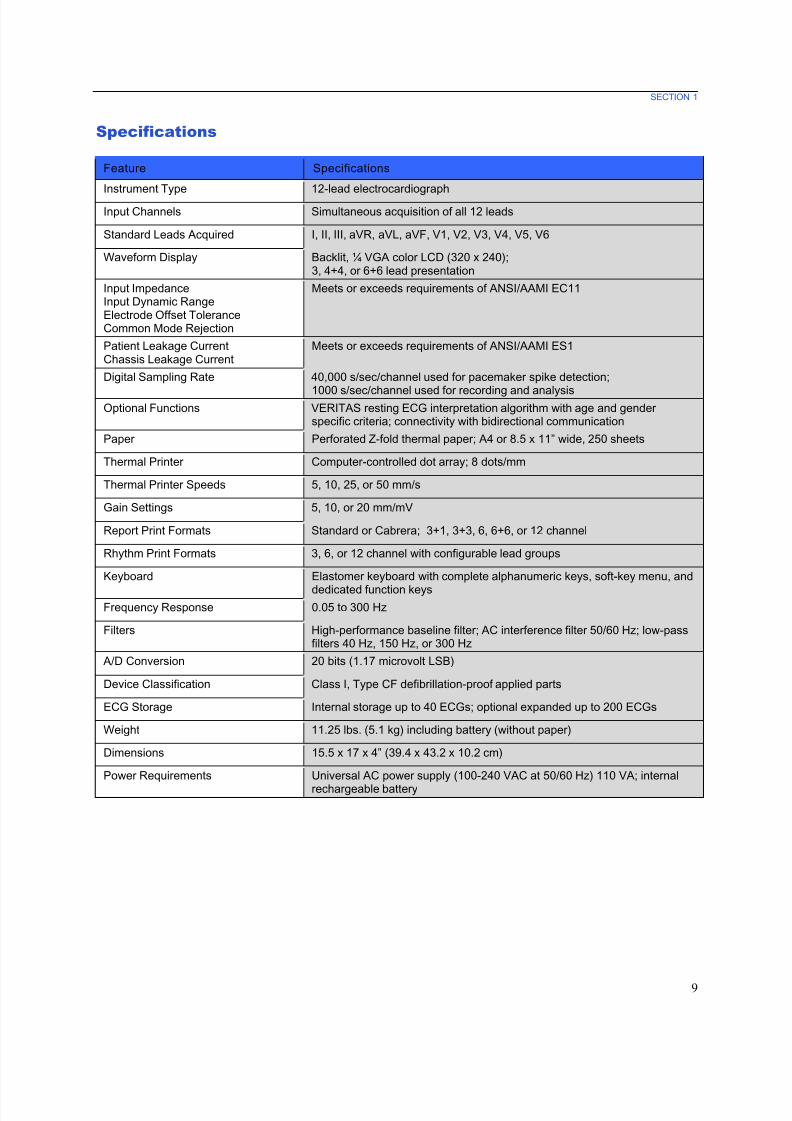
Specifications
Feature Specifications
Instrument Type 12-lead electrocardiograph
Input Channels Simultaneous acquisition of all 12 leads
Standard Leads Acquired I, II, III, aVR, aVL, aVF, V1, V2, V3, V4, V5, V6
Waveform Display Backlit, ¼ VGA color LCD (320 x 240);3, 4+4, or 6+6 lead presentation
Input ImpedanceInput Dynamic RangeElectrode Offset ToleranceCommon Mode Rejection
Meets or exceeds requirements of ANSI/AAMI EC11
Patient Leakage CurrentChassis Leakage Current
Meets or exceeds requirements of ANSI/AAMI ES1
Digital Sampling Rate 40,000 s/sec/channel used for pacemaker spike detection;
1000 s/sec/channel used for recording and analysisOptional Functions VERITAS resting ECG interpretation algorithm with age and gender
specific criteria; connectivity with bidirectional communication
Paper Perforated Z-fold thermal paper; A4 or 8.5 x 11” wide, 250 sheets
Thermal Printer Computer-controlled dot array; 8 dots/mm
Thermal Printer Speeds 5, 10, 25, or 50 mm/s
Gain Settings 5, 10, or 20 mm/mV
Report Print Formats Standard or Cabrera; 3+1, 3+3, 6, 6+6, or 12 channel
Rhythm Print Formats 3, 6, or 12 channel with configurable lead groups
Keyboard Elastomer keyboard with complete alphanumeric keys, soft-key menu, and
dedicated function keysFrequency Response 0.05 to 300 Hz
Filters High-performance baseline filter; AC interference filter 50/60 Hz; low-passfilters 40 Hz, 150 Hz, or 300 Hz
A/D Conversion 20 bits (1.17 microvolt LSB)
Device Classification Class I, Type CF defibrillation-proof applied parts
ECG Storage Internal storage up to 40 ECGs; optional expanded up to 200 ECGs
Weight 11.25 lbs. (5.1 kg) including battery (without paper)
Dimensions 15.5 x 17 x 4” (39.4 x 43.2 x 10.2 cm)
Power Requirements Universal AC power supply (100-240 VAC at 50/60 Hz) 110 VA; internal
rechargeable battery
7/23/2019 Burdick ELI 250 User Manual
http://slidepdf.com/reader/full/burdick-eli-250-user-manual 32/72
SECTION 1
10
Accessories
Replacement Lead sets and Accessories
Part Number Description
9293-046-60 WAM/AM12 10 WIRE REPLACEMENT LEAD SET, AHA BANANA, LIMBS
9293-046-62 WAM/AM12 REPLACEMENT LEADS, AHA BANANA, LIMBS
9293-046-64 WAM/AM12 REPLACEMENT LEADS, AHA BANANA, V1-V3
9293-046-66 WAM/AM12 REPLACEMENT LEADS, AHA BANANA, V4-V6
9293-047-60 WAM/AM12 10 WIRE REPLACEMENT LEAD SET, AHA MEDI-CLIP
9293-047-62 WAM/AM12 REPLACEMENT AHA LEADS, CLIP, LIMBS
9293-047-64 WAM/AM12 REPLACEMENT AHA LEADS, CLIP, V1-V3
9293-047-66 WAM REPLACEMENT AHA LEADS, CLIP, V4-V6
Paper
Part Number Description
9100-026-50 PAPER ELI 250 US CASE/12/250 ZFOLD
Electrodes
Part Number Description
9300-032-50 ECG MONITORING ELECTRODES CASE 300
9300-033-51 ELECTRODE RESTING TAB BOX/500
9300-033-52 ELECTRODE RESTING TAB CASE/5000
Acqu isit ion Modules
Part Number Description
9293-048-52 WIRED PATIENT CABLE (AM12)
30012-019-52 WIRELESS ACQUISITION MODULE (WAM)
Power Cords
Part Number Description
3181-008 POWER CORD US/CAN HOSPITAL 5-15P+320-C13
Manuals
Part Number Description
9515-001-50-CD PHYSICIAN'S GUIDE ADULT & PEDIATRIC UM
9515-166-50-CD ELI LINK USER MANUALS
9515-178-51-CD ELI 250c USER MANUALS
9516-178-51-ENG ELI 250c SERVICE MANUAL
Contact your dealer or go to www.burdick.com for more information.
7/23/2019 Burdick ELI 250 User Manual
http://slidepdf.com/reader/full/burdick-eli-250-user-manual 33/72
EQUIPMENT PREPARATIONSECTION 2
11
Initial Startup
With its initial use, the device requires the user to set certain configurations prior to obtaining any ECGs. The
device will automatically display a language configuration page followed by AC filter frequency, height/weightunits, a set time/date configuration page (including daylight savings time selection), and a configuration page to pair
the WAM™ (wireless acquisition module) if it will be used. (Refer to the WAM user manual for detailed pairinginstructions to the device.)
Connecting the Acquisition Module
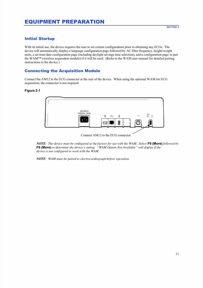
Connect the AM12 to the ECG connector at the rear of the device. When using the optional WAM for ECG
acquisition, the connector is not required.
Figure 2-1
Connect AM12 to the ECG connector
NOTE: The device must be configured at the factory for use with the WAM. Select F6 (More) followed by
F6 (More) to determine the device’s setting. “WAM Option Not Available” will display if the
device is not configured to work with the WAM.
NOTE: WAM must be paired to electrocardiograph before operation.
7/23/2019 Burdick ELI 250 User Manual
http://slidepdf.com/reader/full/burdick-eli-250-user-manual 34/72
SECTION 2
12
Loading Paper
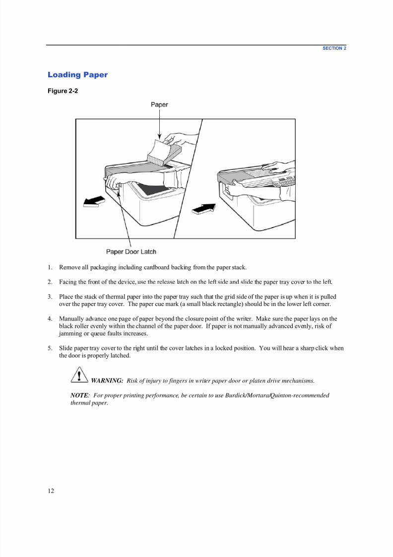
Figure 2-2
1. Remove all packaging including cardboard backing from the paper stack.
2. Facing the front of the device, use the release latch on the left side and slide the paper tray cover to the left.
3. Place the stack of thermal paper into the paper tray such that the grid side of the paper is up when it is pulledover the paper tray cover. The paper cue mark (a small black rectangle) should be in the lower left corner.
4. Manually advance one page of paper beyond the closure point of the writer. Make sure the paper lays on the
black roller evenly within the channel of the paper door. If paper is not manually advanced evenly, risk of
jamming or queue faults increases.
5. Slide paper tray cover to the right until the cover latches in a locked position. You will hear a sharp click when
the door is properly latched.
WARNING: Risk of injury to fingers in writer paper door or platen drive mechanisms.
NOTE: For proper printing performance, be certain to use Burdick/Mortara/Quinton-recommended
thermal paper.
7/23/2019 Burdick ELI 250 User Manual
http://slidepdf.com/reader/full/burdick-eli-250-user-manual 35/72
SECTION 2
13
Applying Power
1. Plug the power cord into an AC wall outlet and into the back of the device. (Reference Figure 1-3.)
2. Press the power ON/OFF button located on the face panel of the device. (Reference Figure 1-5.)
When using AC power, the battery indicator is clear when charging and illuminates in white when fully charged.When using battery power, the battery indicator illuminates in green with a 35% to 100% charge and in yellow with
a 20% to 35% charge. The battery indicator will turn to red when the battery charge is 20% or less.
The device should be connected to AC power for recharging when not in use.
TIP: Battery voltage is displayed at the bottom of the Time/Date screen.
NOTE: There are configurable features on the device that can be used to help prolong battery life (see
Section 4). Proper battery care and maintenance will also help prolong battery life.
CAUTION: The device can be operated on AC line voltage in the absence of a battery or in the
event of an otherwise fully depleted battery. When line voltage is removed the system immediately and
automatically continues on battery power. When the battery voltage is below 10.5V the device will
automatically power down. Once the battery voltage rises above 10.5V the device may be operated on
battery power. It may require up to 30 hours on AC line voltage to recharge the battery from its lowest
level. Routinely discharging a battery to the lowest level will severely shorten the life of the battery.
NOTE: When the On/Off button is depressed for longer than approximately 10 seconds, the
electrocardiograph will do a "hard reboot" and reset the internal clock to default date and time (1-1-2010)
and advise the user to “Set date/time.” When turned on, the user will need to re-enter the date and time.
This requirement may be bypassed if desired and an ECG can be acquired by selecting F6 (Exit) orF5 (Save) , but this ECG will have the date of 1-1-2010. With the next patient the electrocardiograph will
request the operator to enter the proper time and date again.
Low Battery Conditions
To prevent permanent damage to the internal lead-acid battery, the device will automatically power down when the
battery has been depleted to its lowest allowable level. When the device detects that the battery voltage has been
depleted to this level, it will display the messages “ Battery Low – Charge Unit ” for 10 seconds before shuttingdown. Plugging in the AC cord during this time will cause the unit to return to the main acquisition screen.
If the device is in the ECG acquisition mode when the battery voltage is detected at its lowest allowable level, the
unit will display the message “ Battery Low – Charge Unit ”, but will not automatically shut down until the user exitsthe ECG acquisition mode. This allows the user to complete an ECG already in progress.

7/23/2019 Burdick ELI 250 User Manual
http://slidepdf.com/reader/full/burdick-eli-250-user-manual 36/72
SECTION 2
14
Setting Time and Date
1. From real-time ECG view, select F6 (More) followed by F5 (Set Time/Date).
2. Use Enter , Tab, F1 (▲), or F2 (▼) to move through each row. Use the keyboard to type in desired values for
the date and time (using a 24-hour clock).
NOTE: To set time immediately via auto synchronization press F3 (Sync).
3. Use F3 (►) to move through the selections for setting Time Zone and Daylight Savings. To use Daylight
Savings, select Yes. Use F2 (▼) to scroll to, or F4 (Page) to move to the begin/end settings page. Enter the
month, day, and time to begin Daylight Savings and the month, day, and time to end Daylight Savings. UseF1 (▲), F2 (▼), or F4 (Page) to return to the previous screen. If the time zone selected does not supportDaylight Savings, customize a begin and end time by selecting Custom. The Custom setting can also be used to
override the current Daylight Savings settings
TIP: Use the BKSP key to erase entry errors.
NOTE: F4 (Page) is only applicable to view read only (Yes) or change (Custom) a Daylight Savings
setting. F4 (Page) cannot be accessed from the Time Zone setting field.
4. Select F5 (Save) to save changes before exiting.
5. Select F6 (Exit) to return to real-time ECG view. If you did not save before selecting Exit, any changes made
to the time or date will be lost.
NOTE: Date and time may be set to auto synchronization with the cardiology management system if
available. (See section 4, Settings.)
NOTE: In the event of a hard reboot or the loss of battery power, the device will require the date and time
to be re-entered. The device will present a message stating “Set Date/Time.” The user then by depressing
any key (except alt, shift or power) will enter the date and time entry menu. You may bypass this by
selecting F6 (Exit) or F5 (Save).

7/23/2019 Burdick ELI 250 User Manual
http://slidepdf.com/reader/full/burdick-eli-250-user-manual 37/72
SECTION 2
15
Using the WAM or AM12 Acquisition Module
ECG acquisition and rhythm strip printing can also be performed at the WAM or the AM12 acquisition modules.
To use the WAM, refer to the WAM user manual. To use the AM12, refer to the AM12 short-form instruction card.
NOTE: The device must be configured at the factory for use with the WAM. Select F6 (More) followed by
F6 (More) to determine the device’s setting. “WAM Option Not Available” will display if the
device is not configured to work with the WAM.
NOTE: WAM must be paired to electrocardiograph before operation.
Installing the WLAN Antenna
The device with optional WLAN module is shipped with the antenna not installed: the antenna can be found in the
accessory box.
1. Remove the antenna from the accessory box.2. Locate the antenna connector on the back of the device.
3. Mount the antenna on the connector by rotating the antenna clockwise. The antenna must be finger tight to its
connector.4. Locate the built-in hinge and fold the antenna (it will now be at a 90° angle); continue to rotate the antenna
clockwise until it is placed vertically. This will guarantee the best signal for the WLAN module.
NOTE: For more information about the use of the WLAN option, refer to Appendix A.

7/23/2019 Burdick ELI 250 User Manual
http://slidepdf.com/reader/full/burdick-eli-250-user-manual 38/72
SECTION 2
16
7/23/2019 Burdick ELI 250 User Manual
http://slidepdf.com/reader/full/burdick-eli-250-user-manual 39/72
RECORD AN ECGSECTION 3
17
Patient Preparation
Before attaching the electrodes, assure the patient fully understands the procedure and what to expect.
• Privacy is very important in assuring the patient is relaxed.• Reassure the patient that the procedure is painless and that the electrodes on their skin are all that they
will feel.
• Make sure the patient is lying down and is comfortable. If the table is narrow, tuck the patient’s hands
under his/her buttocks to ensure their muscles are relaxed.
• Once all the electrodes are attached, ask the patient to lie still and to not talk. Explain this will assist you in
acquiring a good ECG.
Preparing Patient Skin
Thorough skin preparation is very important. There is natural resistance on the skin surface from various sourcessuch as hair, oil, and dry, dead skin. Skin preparation is intended to minimize these effects and maximize the quality
of the ECG signal.
To prepare the skin:
• Shave hair from electrode sites if necessary.
• Wash area with warm, soapy water.
• Dry skin vigorously with a pad such as 2 x 2 or 4 x 4 gauze to remove dead skin cells and oil, and toincrease capillary blood flow.
NOTE: With elderly or frail patients take care to not abrade the skin causing discomfort or bruising.
Clinical discretion should always be used in patient preparation.
Patient Hookup
Correct electrode placement is important for acquiring a successful ECG.
A good minimum-impedance pathway will provide superior noise-free waveforms. Good quality silver-silver
chloride (Ag/AgCl) electrodes should be used.
TIP: Electrodes should be stored in an air-tight container. Electrodes will dry out if not stored properly
which will cause loss of adhesion and conductivity.
To Attach the Electrodes
1. Expose the arms and legs of the patient to attach the limb leads.2. Place the electrodes on flat, fleshy parts of the arms and legs.
3. If a limb site is not available, place the electrodes on a perfused area of the stump.
4. Attach the electrodes to the skin. A good test for firm electrode contact is to slightly tug on the electrode to
check adhesion. If the electrode moves freely, it needs to be changed. If the electrode does not move
easily, a good connection has been obtained.
7/23/2019 Burdick ELI 250 User Manual
http://slidepdf.com/reader/full/burdick-eli-250-user-manual 40/72
SECTION 3
18
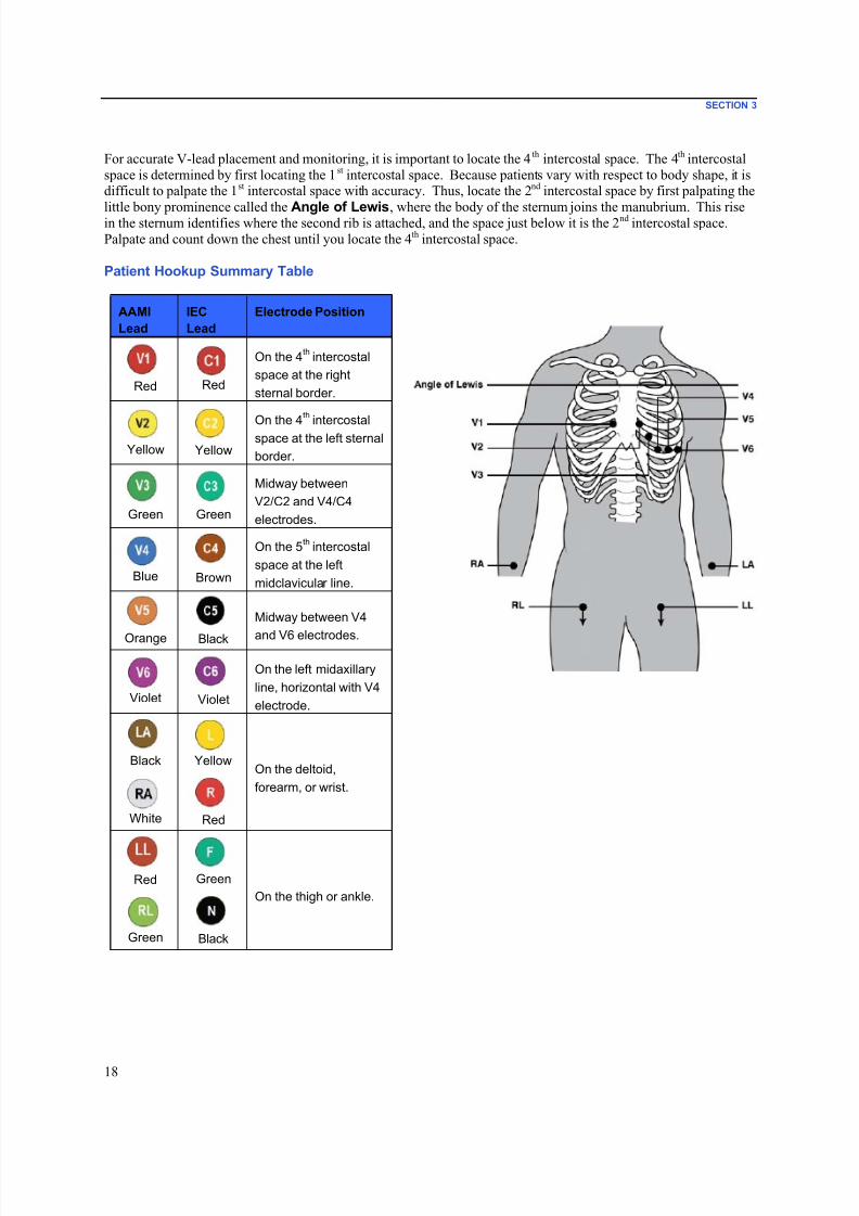
For accurate V-lead placement and monitoring, it is important to locate the 4 th intercostal space. The 4th intercostal
space is determined by first locating the 1 st intercostal space. Because patients vary with respect to body shape, it isdifficult to palpate the 1st intercostal space with accuracy. Thus, locate the 2nd intercostal space by first palpating the
little bony prominence called the Angle of Lewis, where the body of the sternum joins the manubrium. This risein the sternum identifies where the second rib is attached, and the space just below it is the 2nd intercostal space.
Palpate and count down the chest until you locate the 4th intercostal space.
Patient Hookup Summary Table
AAMI
Lead
IEC
Lead
Electrode Position
Red Red
On the 4th intercostal
space at the right
sternal border.
Yellow Yellow
On the 4
th
intercostalspace at the left sternal
border.
Green Green
Midway between
V2/C2 and V4/C4
electrodes.
Blue Brown
On the 5th intercostal
space at the left
midclavicular line.
Orange Black
Midway between V4
and V6 electrodes.
Violet Violet
On the left midaxillary
line, horizontal with V4
electrode.
Black YellowOn the deltoid,
forearm, or wrist.
White Red
Red Green
On the thigh or ankle.
Green Black

7/23/2019 Burdick ELI 250 User Manual
http://slidepdf.com/reader/full/burdick-eli-250-user-manual 41/72
SECTION 3
19
Patient Demographic Entry
Patient demographic information can be entered before acquisition. The entered patient ID fields will remain
populated until you acquire the ECG; however, if you disconnect the leads from the patient, turn off theelectrocardiograph, or change a configuration setting before acquisition, the patient information will be cleared.
To access the patient demographic data entry menu, press F1 (ID) from real-time ECG view. Use the appropriatefunction key to select the desired study group. The patient demographic labels available are determined by the ID
format selected in the configuration settings. In addition to short or long patient ID formats, the device also supports
a custom ID format. The custom format, designed in ELI Link or an E-Scribe™ data management system, can be
downloaded to the device. Additional information about the custom ID can be found in Appendix A, or in the ELILink and E-Scribe user manuals.
Patient demographic entry can be completed manually or automatically using an existing patient record in the
directory. To manually enter the patient demographics, use Enter , Tab, F1 (▲), or F2 (▼) to move to each data
entry field. To enter gender, use F3 (►) to move through the options, or type F or M from the keyboard to change
the gender to female or male. The patient’s date of birth should be entered whenever possible to ensureinterpretation (if set in configuration settings) is as complete as possible.
NOTE: If no age is entered before acquiring an ECG, the interpretation will default to a 40-year old male.
The statement “INTERPRETATION BASED ON A DEFAULT AGE OF 40 YEARS” will be added to the
interpretation text.
NOTE: If an age of zero (0) is used, the interpretation will default to a 6-month old infant. The statement
“INTERPRETATION BASED ON A DEFAULT AGE OF 6 MONTHS” will be added to the interpretation
text.
NOTE: Where global measurement values are not available (i.e., rate, interval, axis), text such as ‘- -‘ or
‘*’ or similar will display/print for the unavailable value.
NOTE: Where mandatory fields have been selected (i.e., Name, ID or Tech Initials), the required field will
be highlighted in red.
When done, select F6 (Done). Skipped fields will appear as a blank field on the header of the ECG printout.
To automatically populate the demographics using an existing patient record, select F5 (Dir) from the ID screen.
Use F1 (▼/▲) to navigate by line down the directory list; use (Shift), F1 (▼/▲) to move up. Similarly, use
F2 (▼▼ /▲▲) to page down the directory list; use (Shift), F2 (▼▼ /▲▲) to page up. To quickly select a
patient name, use the keyboard to enter the first few letters of the last name. The letters will be displayed in the
lower left corner of the display screen and the desired name will automatically be highlighted. Once the desired
name is highlighted, press F3 (Selec) and the patient ID screen will return with all demographic fields populated.
Return to real-time ECG view by selecting F6 (Done).
TIP: Automatically populating demographic fields via the directory is only possible when the ID formats
are the same between records.
NOTE: A password may be required in order to enter the ECG directory. Obtain the password from the
department Administrator.
NOTE: A red ID label indicates there are no entries in the ID demographics, or a required field is missing
from the selected patient demographics.

7/23/2019 Burdick ELI 250 User Manual
http://slidepdf.com/reader/full/burdick-eli-250-user-manual 42/72
SECTION 3
20
Entering Symbols
Punctuation characters, symbols, and/or accented alphanumeric characters (language dependent) can be entered
using the SYM key on the keyboard. Selecting SYM will display 10 special characters at a time. Use F1 (Prev) orF2 (Next) to move to the previous/next set of special characters.
Each special character will have a numeric character located below it. Using the keyboard, press the desired
numeric key to add the corresponding special character. Select SYM or F6 (Done) to exit the symbol entry mode.
Auto-Fill ID
If Auto-Fill ID is enabled in the configuration, the system will automatically populate the demographic fields in the
ID screen. When the patient ID field is manually populated and followed either by selecting F6 (Done) or F2 (▼),the system automatically scans the patient directory. If records with the exact patient ID are found, the existing datais used to fill some of the demographic fields. The auto-fill feature is designed to automatically populate last name,
first name, date of birth, age, and gender only. If no matching records are found, a brief message is displayed and
the user must manually enter the patient’s demographics.
NOTE: In order to avoid the use of incorrect data, the auto-fill feature is only possible when the ID
formats are the same between records.
When time is of the essence or if patient demographics are not available, ID information can be added to the ECGafter it has been acquired via the patient directory. Acquiring an emergency (STAT) or unidentified ECG is
explained in ECG Acquisition, Printing, Storage.
ECG Acquisition, Printing, Storage
Acquisition
Once the patient is connected, the device continuously collects and displays ECG data; therefore, before you press
ECG or RHY you should instruct the patient to relax in a supine position to ensure that the ECG is free from artifact(noise) due to patient activity. If workflow permits patient demographic entry prior to acquisition, enter the patient
identification information as explained in Patient Demographics. After you complete the last data entry field, select
F6 (Done) to return to the real-time ECG view.
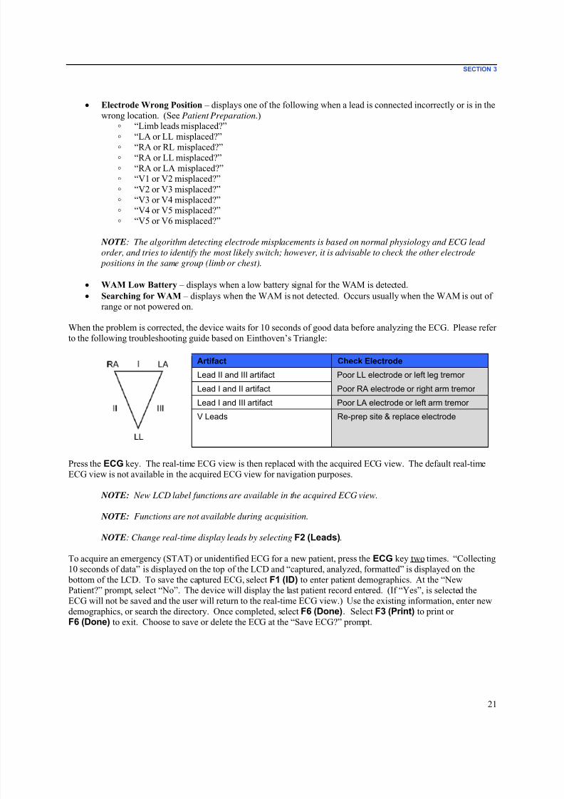
Examine the display for any of the following notification messages:
• Leads Off –displays when patient is not connected.
• Lead Fault –displays faulty lead(s). Re-prep and replace electrode(s) if necessary to obtain satisfactory
waveform(s). (See Patient Preparation.)
7/23/2019 Burdick ELI 250 User Manual
http://slidepdf.com/reader/full/burdick-eli-250-user-manual 43/72
SECTION 3
21
• Electrode Wrong Position – displays one of the following when a lead is connected incorrectly or is in the
wrong location. (See Patient Preparation.)◦ “Limb leads misplaced?”
◦
“LA or LL misplaced?”◦ “RA or RL misplaced?”◦ “RA or LL misplaced?”◦ “RA or LA misplaced?”◦ “V1 or V2 misplaced?”◦ “V2 or V3 misplaced?”◦ “V3 or V4 misplaced?”◦ “V4 or V5 misplaced?”
◦ “V5 or V6 misplaced?”
NOTE: The algorithm detecting electrode misplacements is based on normal physiology and ECG lead
order, and tries to identify the most likely switch; however, it is advisable to check the other electrode
positions in the same group (limb or chest).
• WAM Low Battery – displays when a low battery signal for the WAM is detected.
• Searching for WAM – displays when the WAM is not detected. Occurs usually when the WAM is out of
range or not powered on.
When the problem is corrected, the device waits for 10 seconds of good data before analyzing the ECG. Please refer
to the following troubleshooting guide based on Einthoven’s Triangle:
Artifact Check Electrode
Lead II and III artifact Poor LL electrode or left leg tremor
Lead I and II artifact Poor RA electrode or right arm tremor
Lead I and III artifact Poor LA electrode or left arm tremor
V Leads Re-prep site & replace electrode
Press the ECG key. The real-time ECG view is then replaced with the acquired ECG view. The default real-time
ECG view is not available in the acquired ECG view for navigation purposes.
NOTE: New LCD label functions are available in the acquired ECG view.
NOTE: Functions are not available during acquisition.
NOTE: Change real-time display leads by selecting F2 (Leads).
To acquire an emergency (STAT) or unidentified ECG for a new patient, press the ECG key two times. “Collecting10 seconds of data” is displayed on the top of the LCD and “captured, analyzed, formatted” is displayed on the
bottom of the LCD. To save the captured ECG, select F1 (ID) to enter patient demographics. At the “New
Patient?” prompt, select “No”. The device will display the last patient record entered. (If “Yes”, is selected the
ECG will not be saved and the user will return to the real-time ECG view.) Use the existing information, enter new
demographics, or search the directory. Once completed, select F6 (Done). Select F3 (Print) to print orF6 (Done) to exit. Choose to save or delete the ECG at the “Save ECG?” prompt.
7/23/2019 Burdick ELI 250 User Manual
http://slidepdf.com/reader/full/burdick-eli-250-user-manual 44/72
SECTION 3
22
Best 10 Seconds Selection
The ELI 250c incorporates a 5 minute memory buffer for collection of ECG data. When the Best 10 feature is
enabled, the device will automatically select the best 10 seconds of ECG from within the 5-minute buffer. The best10 seconds is determined based upon measures of high and low-frequency noise found in the 10-second ECGsegments. Should a single limb lead or two precordial lead fail conditions occur, the Best 10 feature is disabled until
the limb lead fail or precordial lead fail condition is resolved. At resolution, the Best 10 feature becomes available
and the selection buffer continues.
Users can switch between BEST 10 or LAST 10 by selecting F5 (More) followed by F5 (Last) or F5 (Best) depending on the current view.
Printing
If Auto-Print is enabled in the configuration, an ECG is printed following acquisition. To print a manual printout,
select F3 (Print).
Toggle through the available waveform display formats (3, 8 or 12 lead) by selecting F2 (Leads). A preview of thefull 10-seconds of ECG waveform is available in the acquired ECG view. The first 5 seconds are shown on the
initial view screen (page 1/2 is displayed in the upper right corner); the second 5 seconds is viewed by selecting
F2 (Leads) again (page 2/2 is displayed in the upper right corner).
If the auto-print configuration is disabled, a 10-second preview will assist in ensuring a quality ECG acquisition
prior to printing. When you acquire an ECG, the electrocardiograph captures the last 10 seconds. The relationship
between the display and the printout is the same – what is displayed in the ECG acquisition view is what will be
printed.
In order to change the speed, gain, filter, or printout format in the acquired ECG view, select F5 (More). To
manipulate the print format of the acquired ECG regardless of the plot format configuration setting, select F4 (Fmt).
Select the function key corresponding to the desired print format. The acquired ECG view is then displayed and to
make an ECG printout copy in the new plot format, select F3 (Print). Select F6 (Done) to return to the real-time
ECG view.
Storage
The device stores and saves all acquired ECGs automatically.
NOTE: Users may delete an acquired ECG from the acquired ECG screen. Once the delete selection has
been made, a confirmation message will appear. Select Yes to permanently delete the record.
7/23/2019 Burdick ELI 250 User Manual
http://slidepdf.com/reader/full/burdick-eli-250-user-manual 45/72
SECTION 3
23
Acquiring Rhythm Strips
Rhythm strips are printed in the format defined in the configuration: 3, 6 or 12 channel for the ELI 250c. See
Section 4 for instructions to configure rhythm leads.
Begin routine rhythm strips by connecting the patient to the device and entering the patient identification
information. After the last data entry field from the ID menu is completed, select F6 (Done) to return to the real-
time ECG view. Select RHY to begin rhythm printing. You can also acquire a rhythm printout by selecting RHY
without entering the patient ID.
NOTE: Rhythm printouts are only possible from the real-time ECG view.
NOTE: Rhythm acquisitions are only printed and not stored in the device.
The rhythm activity screen appears as soon as the printer begins printing the rhythm strip. The waveform display
format is similar to the real-time ECG view; however, new function keys are available during rhythm printing.
In addition to manipulating Speed, Gain, and Filter , the user can toggle different lead groups: change lead groupsduring printing by selecting F2 (Leads). The change in lead groups is apparent on the printout whereas the
waveform display will remain in the default display of 2.5 seconds of Leads I, II, and V1-V6.
During 3-channel rhythm printing, the available lead groups are:
1. Default (user-selected in configuration)2. I-II-III
3. aVR, aVL, aVF
4. V1-V2-V3
5. V4-V5-V6
During 6-channel rhythm printing, the available lead groups are:
1. Default (user-selected in configuration)
2. I-II-III-aVR-aVL-aVF3. V1-V2-V3-V4-V5-V6
During 12-channel rhythm printing, the complete 12 leads are printed simultaneously.
During rhythm printing, place the printer in Standby mode by pressing F6 (Stby). To continue rhythm printing for
the same patient without advancing to a new page, select F6 (Cont). To stop the rhythm printing, press STOP andthe printer will automatically form feed in preparation for a new patient’s rhythm recording or ECG.

7/23/2019 Burdick ELI 250 User Manual
http://slidepdf.com/reader/full/burdick-eli-250-user-manual 46/72
SECTION 3
24
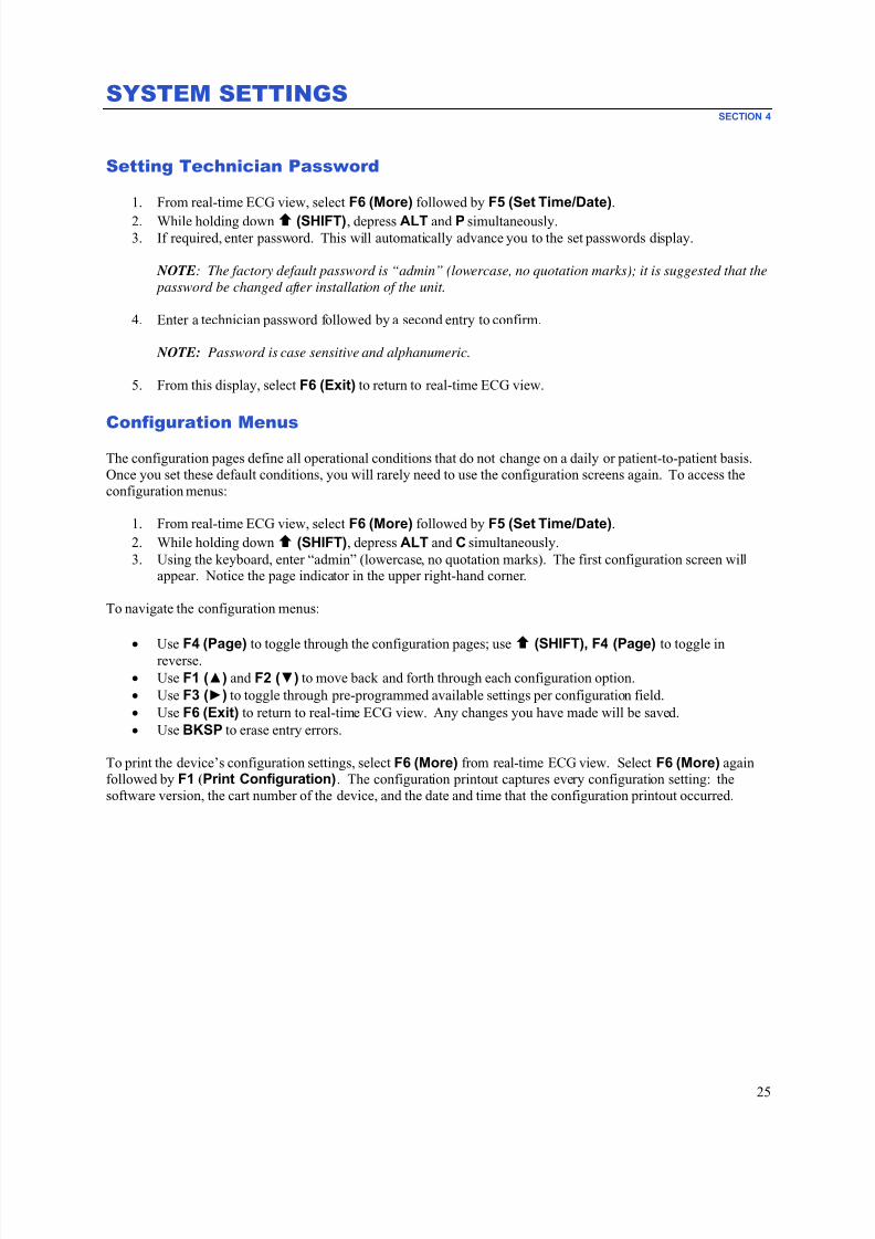
7/23/2019 Burdick ELI 250 User Manual
http://slidepdf.com/reader/full/burdick-eli-250-user-manual 47/72
SYSTEM SETTINGSSECTION 4
25
Setting Technician Password
1. From real-time ECG view, select F6 (More) followed by F5 (Set Time/Date).
2. While holding down (SHIFT), depress ALT and P simultaneously.3. If required, enter password. This will automatically advance you to the set passwords display.
NOTE: The factory default password is “admin” (lowercase, no quotation marks); it is suggested that the
password be changed after installation of the unit.
4. Enter a technician password followed by a second entry to confirm.
NOTE: Password is case sensitive and alphanumeric.
5. From this display, select F6 (Exit) to return to real-time ECG view.
Configuration Menus
The configuration pages define all operational conditions that do not change on a daily or patient-to-patient basis.
Once you set these default conditions, you will rarely need to use the configuration screens again. To access the
configuration menus:
1. From real-time ECG view, select F6 (More) followed by F5 (Set Time/Date).
2. While holding down (SHIFT), depress ALT and C simultaneously.
3. Using the keyboard, enter “admin” (lowercase, no quotation marks). The first configuration screen willappear. Notice the page indicator in the upper right-hand corner.
To navigate the configuration menus:
•
UseF4 (Page)
to toggle through the configuration pages; use (SHIFT), F4 (Page)
to toggle inreverse.
• Use F1 (▲) and F2 (▼) to move back and forth through each configuration option.
• Use F3 (►) to toggle through pre-programmed available settings per configuration field.
• Use F6 (Exit) to return to real-time ECG view. Any changes you have made will be saved.
• Use BKSP to erase entry errors.
To print the device’s configuration settings, select F6 (More) from real-time ECG view. Select F6 (More) again
followed by F1 (Print Configuration). The configuration printout captures every configuration setting: the
software version, the cart number of the device, and the date and time that the configuration printout occurred.
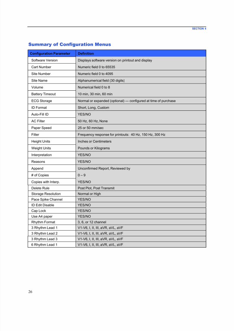
7/23/2019 Burdick ELI 250 User Manual
http://slidepdf.com/reader/full/burdick-eli-250-user-manual 48/72
SECTION 4
26
Summary of Configuration Menus
Configuration Parameter Definition
Software Version Displays software version on printout and display
Cart Number Numeric field 0 to 65535
Site Number Numeric field 0 to 4095
Site Name Alphanumerical field (30 digits)
Volume Numerical field 0 to 8
Battery Timeout 10 min, 30 min, 60 min
ECG Storage Normal or expanded (optional) — configured at time of purchase
ID Format Short, Long, Custom
Auto-Fill ID YES/NO AC Filter 50 Hz, 60 Hz, None
Paper Speed 25 or 50 mm/sec
Filter Frequency response for printouts: 40 Hz, 150 Hz, 300 Hz
Height Units Inches or Centimeters
Weight Units Pounds or Kilograms
Interpretation YES/NO
Reasons YES/NO
Append Unconfirmed Report, Reviewed by
# of Copies 0 – 9
Copies with Interp. YES/NO
Delete Rule Post Plot, Post Transmit
Storage Resolution Normal or High
Pace Spike Channel YES/NO
ID Edit Disable YES/NO
Cap Lock YES/NO
Use A4 paper YES/NO
Rhythm Format 3, 6, or 12 channel
3 Rhythm Lead 1 V1-V6, I, II, III, aVR, aVL, aVF
3 Rhythm Lead 2 V1-V6, I, II, III, aVR, aVL, aVF
3 Rhythm Lead 3 V1-V6, I, II, III, aVR, aVL, aVF
6 Rhythm Lead 1 V1-V6, I, II, III, aVR, aVL, aVF
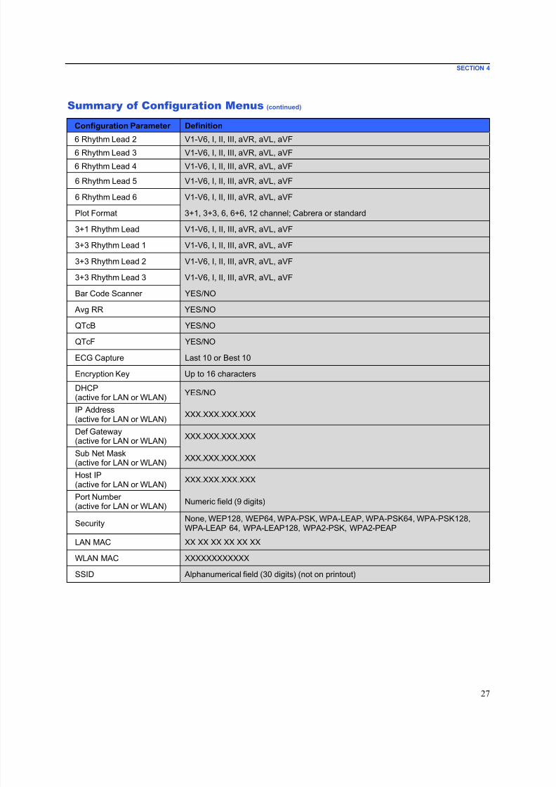
7/23/2019 Burdick ELI 250 User Manual
http://slidepdf.com/reader/full/burdick-eli-250-user-manual 49/72
SECTION 4
27
Summary of Configuration Menus (continued)
Configuration Parameter Definition
6 Rhythm Lead 2 V1-V6, I, II, III, aVR, aVL, aVF
6 Rhythm Lead 3 V1-V6, I, II, III, aVR, aVL, aVF
6 Rhythm Lead 4 V1-V6, I, II, III, aVR, aVL, aVF
6 Rhythm Lead 5 V1-V6, I, II, III, aVR, aVL, aVF
6 Rhythm Lead 6 V1-V6, I, II, III, aVR, aVL, aVF
Plot Format 3+1, 3+3, 6, 6+6, 12 channel; Cabrera or standard
3+1 Rhythm Lead V1-V6, I, II, III, aVR, aVL, aVF
3+3 Rhythm Lead 1 V1-V6, I, II, III, aVR, aVL, aVF
3+3 Rhythm Lead 2 V1-V6, I, II, III, aVR, aVL, aVF
3+3 Rhythm Lead 3 V1-V6, I, II, III, aVR, aVL, aVF
Bar Code Scanner YES/NO
Avg RR YES/NO
QTcB YES/NO
QTcF YES/NO
ECG Capture Last 10 or Best 10
Encryption Key Up to 16 characters
DHCP(active for LAN or WLAN)
YES/NO
IP Address(active for LAN or WLAN) XXX.XXX.XXX.XXX
Def Gateway(active for LAN or WLAN)
XXX.XXX.XXX.XXX
Sub Net Mask(active for LAN or WLAN)
XXX.XXX.XXX.XXX
Host IP(active for LAN or WLAN)
XXX.XXX.XXX.XXX
Port Number(active for LAN or WLAN)
Numeric field (9 digits)
SecurityNone, WEP128, WEP64, WPA-PSK, WPA-LEAP, WPA-PSK64, WPA-PSK128,WPA-LEAP 64, WPA-LEAP128, WPA2-PSK, WPA2-PEAP
LAN MAC XX XX XX XX XX XX
WLAN MAC XXXXXXXXXXXX
SSID Alphanumerical field (30 digits) (not on printout)
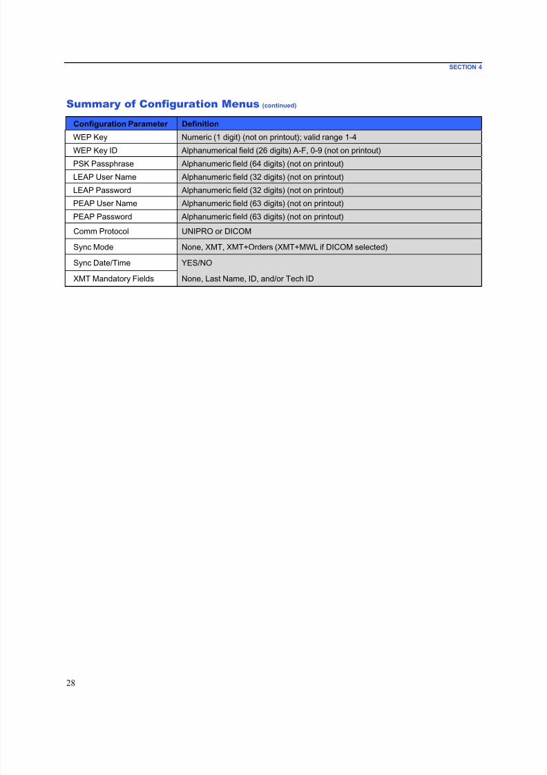
7/23/2019 Burdick ELI 250 User Manual
http://slidepdf.com/reader/full/burdick-eli-250-user-manual 50/72
SECTION 4
28
Summary of Configuration Menus (continued)
Configuration Parameter Definition
WEP Key Numeric (1 digit) (not on printout); valid range 1-4
WEP Key ID Alphanumerical field (26 digits) A-F, 0-9 (not on printout)
PSK Passphrase Alphanumeric field (64 digits) (not on printout)
LEAP User Name Alphanumeric field (32 digits) (not on printout)
LEAP Password Alphanumeric field (32 digits) (not on printout)
PEAP User Name Alphanumeric field (63 digits) (not on printout)
PEAP Password Alphanumeric field (63 digits) (not on printout)
Comm Protocol UNIPRO or DICOM
Sync Mode None, XMT, XMT+Orders (XMT+MWL if DICOM selected)
Sync Date/Time YES/NO
XMT Mandatory Fields None, Last Name, ID, and/or Tech ID
7/23/2019 Burdick ELI 250 User Manual
http://slidepdf.com/reader/full/burdick-eli-250-user-manual 51/72
SECTION 4
29
Configuration Settings
Software Version
Identifies the software version of your electrocardiograph.
Cart Number
Indicates which electrocardiograph acquired or transmitted a particular ECG.
Site Number
Identifies the site of your device. Site numbers designate the hospital, clinic, or institution for ECG records stored inan E-Scribe system and must be defined for transmitting and retrieving ECGs from that system. You can use up to
four digits for the site number. Numbers from 0 – 4095 are supported.
Site Name
Defines your clinic, hospital, or office name. You can enter up to 30 alphanumeric characters. The site name prints
at the bottom, left edge of the ECG printout.
Language
There are several languages available on the electrocardiograph.
CAUTION: Function labels are immediately translated upon selecting a new language and exiting
the configuration screen.
If an unknown language is visible, use the following steps to revert to the language of your country:
1. F6 (More) from real-time ECG view.
2. Select F5 (Set Time/Date). 3. Simultaneously press (SHIFT) + ALT + C. 4. Enter password (“admin”)
5. Press F2 (▼) four times.
6. Press F3 (►) until the desired language appears.
7. F6 (Exit) to return to real-time ECG view.
Alphabets of specific languages may require use of special characters in demographic fields. This is accomplished
by using the SYM key on the keyboard.
Volume
Defines the keyboard click loudness. Available settings range from 0 (off) to 8 (loud).
Battery Time Out
Determines when the electrocardiograph will switch off in order to conserve the battery life of the device. The
battery time out will only occur if the keyboard has not been depressed for the time specified. The battery time out
setting is ignored if an active ECG signal is detected during transmission or while rhythm printing.

7/23/2019 Burdick ELI 250 User Manual
http://slidepdf.com/reader/full/burdick-eli-250-user-manual 52/72
SECTION 4
30
ECG Storage
Indicates ECG storage capacity. Normal indicates standard memory capacity of 40 patient records. Expanded
indicates the optional expanded memory (200 patient records) has been installed.
ID Format
Defines the format for the patient demographic information prompts. There are two standard formats: short or long.
A custom ID format can be downloaded from ELI Link or an E-Scribe system. See Appendix A to download a
custom ID.
The short format includes the patient's last and first name, patient ID number, date of birth (automatically calculates
the age), and gender.
The long format is identical to the standard format except that it includes the patient's first name, room, and
comment fields.
Auto-Fill ID
When enabled, the device will automatically populate last name, first name, date of birth, age, and gender in the ID
screen if records with matching patient ID are found in the ECG directory.
AC Filter
The device removes 60 Hz or 50 Hz interference. The setting you select depends on the line frequency in yourcountry. Always use the 60 Hz setting in the U.S. If AC interference is present, check to see that the proper AC
filter is selected.
Paper Speed
Configure to 25 mm/s or 50 mm/s for default ECG printouts. For rhythm printouts and display, speeds of 5 mm/s or10 mm/s are also available. See Section 3 to change speeds for display or rhythm printing. Paper speed is printed at
the bottom right corner of the ECG printout.
Filter
The ECG plot-frequency filter (or print filter) can be set to 0.05 to 40 Hz, 0.05 to 150 Hz, or 0.05 to 300 Hz. The
plot-frequency filter does not filter the acquired digital record. A 40 Hz plot-filter setting will reduce the noise
(40 Hz and higher frequencies) on the printed ECG, and a 150 Hz plot-filter setting will reduce the noise (150 Hzand higher frequencies) on the printout; a 300 Hz plot-filter setting will not filter the printed ECG. The filter setting
is printed at the bottom right corner of the ECG printout.
Height Units
Weight Units
Defines the units of height (in/cm) and weight (lb/kg). Settings are selected independently of each other, allowing
for metric or U.S. forms of measurement to be used simultaneously or separately.
7/23/2019 Burdick ELI 250 User Manual
http://slidepdf.com/reader/full/burdick-eli-250-user-manual 53/72
SECTION 4
31
Interpretation
The device automatically analyzes ECGs and prints the optional interpretation on the ECG printout. This setting
allows you to select or suppress the “interpretive” text on the ECG report.
NOTE: The ECG interpretations offered by the device are only significant when used in conjunction with
a physician over-read as well as consideration of all other relevant patient data.
Reasons
The reasons statements indicate why a particular interpretive statement was printed. Reasons statements print
enclosed in [square brackets] within the interpretive text if the interpretation option is turned on. Turning the
reasons statement function on or off does not affect the measurements performed or the interpretive statementsselected by the analysis program.
For Example: Anteroseptal Infarct [40+ ms Q WAVE IN V1-V4]
Where “Anteroseptal Infarct” is the interpretive statement,
and “40+ ms Q WAVE IN V1-V4” is the reason statement or explanation as to why the
interpretive statement was printed.
Append
A status or statement phrase can be appended to the ECG and printed under the interpretive text printout. Either
“unconfirmed report” or “reviewed by” can be selected.
Number of Copies
Defines the number of printed copies when an ECG is taken. A zero (0) setting prints no ECG; one (1) prints the
original; two (2) prints the original plus 1 copy, and so on. Up to 9 copies may be selected.
Copies with Interpretation
Defines whether or not printed copies will include interpretation. The clinician may request the first ECG printout
with the interpretation included. Additional copies may be printed with or without the interpretation.
Delete Rule
Defines the rule to mark ECGs as deleted in the ECG directory. ECGs that are marked for deletion will beautomatically removed or erased based on their acquisition date (a first-in/first-out philosophy) to make room for the
new ECG record. ECGs are only erased from the directory when they are marked for deletion and if the directory
becomes full. More than one ECG may be removed from the directory in order to make room for the new incoming
record. The delete rule selections are:
Post Plot = ECG is automatically marked for deletion after printing
Post Transmit = ECG is automatically marked for deletion after transmission
Storage Resolution
Dictates the resolution of all stored ECG records. The resolution setting is either Normal or High. If the value is set
to High, the stored ECG will have a high resolution. As a result, the record size will be large and will reduce thestorage capacity in the ECG directory.
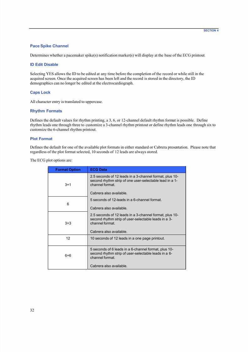
7/23/2019 Burdick ELI 250 User Manual
http://slidepdf.com/reader/full/burdick-eli-250-user-manual 54/72
SECTION 4
32
Pace Spike Channel
Determines whether a pacemaker spike(s) notification marker(s) will display at the base of the ECG printout.
ID Edit Disable
Selecting YES allows the ID to be edited at any time before the completion of the record or while still in the
acquired screen. Once the acquired screen has been left and the record is stored in the directory, the ID
demographics can no longer be edited at the electrocardiograph.
Caps Lock
All character entry is translated to uppercase.
Rhythm Formats
Defines the default values for rhythm printing, a 3, 6, or 12-channel default rhythm format is possible. Define
rhythm leads one through three to customize a 3-channel rhythm printout or define rhythm leads one through six to
customize the 6-channel rhythm printout.
Plot Format
Defines the default for one of the available plot formats in either standard or Cabrera presentation. Please note that
regardless of the plot format selected, 10 seconds of 12 leads are always stored.
The ECG plot options are:
Format Option ECG Data
3+1
2.5 seconds of 12 leads in a 3-channel format, plus 10-second rhythm strip of one user-selectable lead in a 1-
channel format.
Cabrera also available.
65 seconds of 12-leads in a 6-channel format.
Cabrera also available.
3+3
2.5 seconds of 12 leads in a 3-channel format, plus 10-second rhythm strip of user-selectable leads in a 3-channel format.
Cabrera also available.
12 10 seconds of 12 leads in a one page printout.
6+6
5 seconds of 6 leads in a 6-channel format, plus 10-second rhythm strip of user-selectable leads in a 6-channel format.
Cabrera also available.

7/23/2019 Burdick ELI 250 User Manual
http://slidepdf.com/reader/full/burdick-eli-250-user-manual 55/72
SECTION 4
33
Rhythm Leads
Displays continuous rhythm of selected ECG leads and permits printing of selected leads. User may toggle between
selected leads, system set leads, or I, II, III, aVR, aVL, and aVF followed by V1, V2, V3, V4, V5, and V6.
NOTE: Rhythm acquisition is not stored in memory, only printed.
NOTE: See Section 3 to acquire a rhythm printout.
Bar Code Scanner
Enabling this option will allow for the use of a Burdick-approved USB bar code scanner.
Average RR
Enabling this option will display an averaged RR value to appear on the report.
QTcB
Enabling this option will display a Bazett’s corrected QT value on the report along with the default linear
QTc value.
QTcF
Enabling this option will display a Fridericia corrected QT value on the report along with the default linear
QTc value.
ECG Capture
Up to 5 minutes accumulated ECG data can be acquired internally for use with the Best 10 feature. The device
automatically selects the best 10 seconds from within the 5-minute buffer.
Users can switch between BEST 10 or LAST 10 by selecting F5 (More) followed by F5 (Last) or F5 (Best) depending on the current view.
Encryption Key
Encryption Key is a sequence of numbers used to encrypt or decrypt data and can consist of up to 16 alpha/numeric
characters. All transmissions from ELI 250c are sent using AES 256 bit encryption. The encryption key in theconfig menu allows the user to set a custom pre-shared key between the cart and ELI Link version 4.00 or later (all
carts transmitting to one ELI Link must share the key) otherwise a default hidden key will be used.

7/23/2019 Burdick ELI 250 User Manual
http://slidepdf.com/reader/full/burdick-eli-250-user-manual 56/72
SECTION 4
34
DHCP
Defines whether the Dynamic Host Communication Protocol (DHCP) will be used to obtain an IP address. If DHCP
is Yes, the network will automatically and dynamically assign an IP address. If DHCP is No, you must enter the IPaddress, def gateway, and sub net mask.
NOTE: All parameters related to network connection must be entered under the direction of the IT
Manager of the facility where the device is installed. See Appendix A for more information on device
connectivity settings.
NOTE: Network settings for LAN (first page of settings) and those for WLAN or GPRS (second page of
settings) are independent from each other.
IP Address
Enter the fixed IP address for network transmissions (if DHCP is not selected).
NOTE: An IP address will be required for both LAN and WLAN applications.
Def Gateway
Enter the address of the default gateway (if DHCP is not selected).
Sub Net Mask
Enter the sub net address (if DHCP is not selected).
Host IP
Enter the IP address of the host server.
NOTE: Addresses are always entered as 4 sets of 3 digits; therefore, an address of 192.168.0.7 must be
entered as 192.168.000.007.
Port Number
Enter the port number used by the host server.
LAN MAC
Shows the MAC address of the LAN.
Security (WEP)
Wired Equivalent Privacy (WEP) is an encrypted security protocol (part of the 802.11 standard). Access points can
have multiple WEP keys stored. Each one of them is identified by a number (e.g., 1, 2, 3, 4).
WEP Key
Enter the WEP key number.
7/23/2019 Burdick ELI 250 User Manual
http://slidepdf.com/reader/full/burdick-eli-250-user-manual 57/72
SECTION 4
35
WEP Key ID
Enter the 128-bit WEP key ID value (26 digits in 13 sets of two digits).
WLAN MAC
Shows the MAC address of the device’s wireless module for configuring access points.
SSID
Service Set Identifier (SSID) is the name of the wireless network. This field is case sensitive.
WPA-PSK/WPA2-PSK
Allows for implementation of the “personal mode” of WPA. This mode of encryption employs Temporal Key
Integrity Protocol (TKIP) which dynamically changes keys as the system is used.
PSK Passphrase
The passphrase may be from eight to 63 ASCII characters or 64 hexadecimal digits (256 bits).
WPA-LEAP
Cisco® LEAP (Light Extensible Authorization Protocol) enables use of the device with wireless networks
employing the LEAP encryption protocol.
LEAP User Name
User name can be up to 32 characters in length.
LEAP Password
LEAP password can contain up to 32 characters.
WPA2-PEAP
Enables use of the device with wireless networks employing the PEAP encryption protocol.
PEAP User Name
User name can be up to 63 characters in length.
PEAP Password
Password can contain up to 63 characters.
Access Point Name
Access Point Name can be up to 120 characters in length.

7/23/2019 Burdick ELI 250 User Manual
http://slidepdf.com/reader/full/burdick-eli-250-user-manual 58/72
SECTION 4
36
Access Point User Name
Access Point User Name can be up to 120 characters in length.
Access Point Password
Access Point Password can be up to 120 characters in length.
Comm. Protocol
Select UNIPRO OR DICOM. DICOM is only available if the DICOM option has been installed.
NOTE: This parameter must be entered under the direction of the IT Manager of the facility where the
device is installed.
NOTE: Units ship by default with Comm. Protocol set to UNIPRO or DICOM. The UNIPRO or DICOM
setting is not supported by E-Scribe or ELI Link versions prior to V4.00. For questions about compatibilityof your device with ELI Link and UNIPRO or DICOM, contact Technical Support.
Sync Mode
Select None, XMT, or XMT+Orders (XMT+MWL if DICOM enabled). None requires a manual transmission of
reports and then a second manual request to receive orders from the cardiology management system. XMT will
automatically transmit the report; XMT+Orders will both transmit the report and retrieve the orders.
Sync Date/Time
Select Yes or No. Yes will synchronize the date/time with the approved cardiology management system. With No,
there will be no date/time synchronization. Date/time synchronization is done through ELI Link V4.00 or later.
XMT Mandatory Fields
Defines fields required for ECG transmission to the cardiology management system. None will allow datatransmission without limitation; Last Name requires the technician to enter a minimum of the Last Name; ID
requires the technician to enter a minimum of the patient’s ID; Tech ID requires the technician to enter a minimum
of the technician’s initials. You may also select each of these independently allowing for any multiple requiredselections as well.

7/23/2019 Burdick ELI 250 User Manual
http://slidepdf.com/reader/full/burdick-eli-250-user-manual 59/72
ECG DIRECTORYSECTION 5
37
The standard ECG directory saves up to 40 individual ECG records. The optional expanded memory permits up to
200 individual ECG records.
To access the ECG directory, select F6 (More) followed by F1 (Directory of Stored ECGs) from the real-timeECG view.
NOTE: A password may be required in order to enter the ECG directory. Obtain the password from the
department Administrator.
NOTE: In the ECG directory list, “P” represents the record has been printed, “X” represents the record
has a delete status, and “T” represents the record has been transmitted.
NOTE: Records marked for deletion will be maintained on the display.
Management of the ECG record is performed within the directory of stored ECGs. The desired record must behighlighted in order to view, print, edit, add demographics, or to change delete status.
Use F1 (▼/▲) to navigate by line down the ECG directory; use (Shift), F1 (▼/▲) to move up. Similarly, use
F2 (▼▼ /▲▲) to page down the ECG directory; use (Shift), F2 (▼▼ /▲▲) to page up. To quickly select a
patient name, use the keyboard to enter the first few letters of the last name. The letters will be displayed in the
lower left corner of the display screen and the desired name will automatically be highlighted.
An ECG may be stored in the directory but have a “delete status” (indicated by “X”). The directory saves records
marked for deletion in the event that you may want to recover the ECG at a later time. Records are automatically
marked for deletion based on the delete rule configuration (see Section 4). To manually mark an ECG record for
deletion, highlight a name from the ECG directory and select F4 (Delet). An “X” will appear in the far right-hand
column of the directory. To remove the delete status, re-highlight the name and select F4 again. All stored ECGs
will remain in the directory until it becomes full. When necessary to store a newly acquired ECG, only those
records that have been marked for deletion will be removed.
To view a specific ECG record, highlight the desired name from the directory list and press F3 (Selec). The
selected ECG is presented in acquired ECG view. Toggle through the available waveform formats by selecting
F2 (Leads). To make an additional copy of the ECG, select F3 (Print). To view or change the patient
demographics, select F1 (ID). To return to the ECG directory, select F6 (Done).
In order to change the speed, gain, filter, or printout format in the acquired ECG view, select F5 (More). To
manipulate the print format of the acquired ECG regardless of the plot format configuration setting, select F4 (Fmt).Select the desired plot format setting and return to the acquired ECG view.
The directory is easily sorted either by name, ID, or date. To sort the ECG records, select F5 (More) from the ECG
directory.
• Select F1 to sort the directory by patient name (patient ID and time/date are displayed in the top row)
•
Select F2 to sort the directory by patient ID (patient name is displayed in the top row)
• Select F3 to sort the directory by acquisition date (patient name is displayed in the top row)
To make a printout of the ECG directory, select F4 (Print Directory). The directory lists stored ECGs based on
how you have the directory sorted. The printout indicates if the ECGs have been printed, marked delete, or
transmitted with an “X” in the appropriate column. Select F6 (Exit) to return to the ECG directory.

7/23/2019 Burdick ELI 250 User Manual
http://slidepdf.com/reader/full/burdick-eli-250-user-manual 60/72
SECTION 5
38
ECG Order List
To display the ECG order list, select F4 (Order) from the patient ID screen. The ECG order list is comparable to
the ECG directory in looks and in practice; you can sort the list by name, ID, or date. To sort the orders, first selectF5 (More):
Select F1 to sort the orders by patient name (ID, time, and date are displayed in the top row)
Select F2 to sort the orders by patient ID (name is displayed in the top row)
Select F3 to sort the orders by acquisition date (name is displayed in the top row)
To make a printout of the orders list, select F4 (Print Orders). Select F6 (Exit) to return to the ECG order list.
NOTE: A password may be required in order to enter the ECG Order List. Obtain the password from the
department Administrator.

7/23/2019 Burdick ELI 250 User Manual
http://slidepdf.com/reader/full/burdick-eli-250-user-manual 61/72
CONNECTIVITY AND ECG TRANSMISSIONAPPENDIX A
39
ECG Transmission
You may transmit ECGs to ELI Link, or to a third party EMR using an optional factory installed LAN, or WLAN;
all the mentioned transmission modes can use the Mortara UNIPRO or DICOM communication protocol.
NOTE: Units ship by default with Comm Protocol set to UNIPRO. The UNIPRO setting is not supported
by E-Scribe versions prior to V8.10 or ELI Link versions prior to V3.10. For questions about compatibility
of your device with E-Scribe or ELI Link and UNIPRO, contact Technical Support.
Before transmitting ECGs, certain configuration options must be set in system settings depending upon the
transmission media used and the electronic storage media you are transmitting to (see Section 4).
The WLAN performance of the device may vary due to changes in RF (radio frequency) properties at your site or toenvironmental conditions. If you are experiencing intermittent connectivity in certain areas of your facility, it may
be necessary to re-initiate the transmission process. You can also consult your hospital IT department or your
technical service representative regarding modification of your WLAN to improve system performance.
To transmit records, select SYNC. To stop transmissions, use the STOP key.
To transmit one ECG, select F2 (Selec) to choose a record from the patient directory. Use F1 (▼/▲) to navigate
by line down the directory list; use (Shift), F1 (▼/▲) to move up. Similarly, use F2 (▼▼ /▲▲) to page down
the directory list; use (Shift), F2 (▼▼ /▲▲) to page up. To quickly select a patient name, use the keyboard to
enter the first few letters of the last name. The letters will be displayed in the lower left corner of the display screen
and the desired name will automatically be highlighted. When the desired record is highlighted, use F3 (Sync) totransmit the individual ECG.
To batch transmit all records in the directory, select F1 (Batch). In a batch transmission, only those records which
have not been previously transmitted or marked for deletion will be transmitted. After the transmission of your
record(s), the real-time ECG view is displayed
7/23/2019 Burdick ELI 250 User Manual
http://slidepdf.com/reader/full/burdick-eli-250-user-manual 62/72
APPENDIX A
40
LAN Transmission
For a LAN transmission, connect the ethernet cable to the LAN connection at the rear of the device and set the Sync
media to LAN in the configuration. It is necessary that the IT Manager of your facility set the device’s LANconfiguration values.
NOTE: Addresses are always entered as 4 sets of 3 digits; therefore, an address of 192.168.0.7 must be
entered on the device as 192.168.000.007.
CAUTION : Possible damage to the device may occur if telephone cable is connected to the LAN
connector.
Ethernet Status LEDs
The device’s LAN will support 10 and 100 mbps networks.
At the external LAN interface connector, the user is presented with two LEDs (Light Emitting Diodes). The two
status indicator LEDs provide signals for “link status” and “packet transmit/receive”. As the external connector is
viewed from the outside rear of the device, the left LED remains illuminated when the network link is detected. The
right LED flashes when a transmit or receive packet occurs or any traffic on the network is detected.
If DHCP is set to NO, your LAN access point will have a static network setting and the following parameters must
be configured in the device:
IP AddressDefault Gateway
Sub Net Mask
If DHCP is set to YES, your LAN access point will have an automatic network setting and IP address; default
gateway and sub net mask do not need to be configured. In either DHCP setting, the following network parametersmust be provided by your IT Manager:
Host IPPort Number
NOTE: Addresses are always entered as 4 sets of 3 digits; therefore, an address of 192.168.0.7 must be
entered on the device as 192.168.000.007.
NOTE: All parameters related to network connection must be entered under the direction of the IT
Manager of the facility where the device is installed. See also Appendix A for more information on device
connectivity settings.
NOTE: Network settings for LAN (first page of settings) and those for WLAN or GPRS (second page of
settings) are independent from each other.
If WEP security is disabled on your access point, then set security (WEP) to NO. If WEP security is enabled on
your access point, the following wireless network parameters must be configured in the device by the IT Manager:
Security: WEP
WEP KeyWEP Key ID
NOTE: The range for the WEP key is 0-3. If the range on your access point is 1-4, then 0 at the device
maps to 1 on the access point; 1 maps to 2 on the access point, etc.

7/23/2019 Burdick ELI 250 User Manual
http://slidepdf.com/reader/full/burdick-eli-250-user-manual 63/72
APPENDIX A
41
If your wireless security environment is WPA or WPA2 (Wi-fi Protected Access) then you will need to enter:
Security: WPA-PSK or WPA2-PSKPassphrase:
NOTE: The passphrase length is limited to 64 characters.
If your wireless security environment is LEAP then you will need to enter:
Security: WPA-LEAP
LEAP User Name
LEAP Password
NOTE: LEAP user name and password are limited to 32 characters.
If your wireless security environment is PEAP then you will need to enter:
Security: WPA2-PEAP
PEAP User NamePEAP Password
NOTE: PEAP user name and password are limited to 63 characters.

7/23/2019 Burdick ELI 250 User Manual
http://slidepdf.com/reader/full/burdick-eli-250-user-manual 64/72
APPENDIX A
42
WLAN Transmission
For a WLAN transmission, set the Sync media to WLAN. It is necessary that the IT Manager of your facility
configure the wireless access point(s) and E-Scribe workstation. It is also required that your IT Manager provide thedevice’s WLAN configuration values. The device can be configured for Dynamic Host Communication Protocol
(DHCP) or static IP. Wireless security encryption options include WEP, WPA, WPA2, LEAP, and PEAP.
NOTE: Environmental conditions may affect the reliability of WLAN transmissions.
NOTE: The location for antenna for GPRS and WLAN are interchangeable.
If DHCP is set to NO, your wireless access point will have a static network setting and the following parametersmust be configured in the device:
IP Address
Default Gateway
Sub Net Mask
If DHCP is set to YES, your wireless access point will have an automatic network setting and IP address; defaultgateway and sub net mask do not need to be configured. In either DHCP setting, the following wireless network
parameters must be provided by your IT Manager:
Host IP
Port Number
SSID
Channel Number
NOTE: Addresses are always entered as 4 sets of 3 digits; therefore, an address of 192.168.0.7 must be
entered on the device as 192.168.000.007.
NOTE: All parameters related to network connection must be entered under the direction of the IT
Manager of the facility where the device is installed. See also Appendix A for more information on device
connectivity settings.
NOTE: Network settings for LAN (first page of settings) and those for WLAN or GPRS (second page of
settings) are independent from each other.
If WEP security is disabled on your access point, then set security (WEP) to NO. If WEP security is enabled onyour access point, the following wireless network parameters must be configured in the device by the IT Manager:
Security: WEP
WEP KeyWEP Key ID
NOTE: The range for the WEP key is 0-3. If the range on your access point is 1-4, then 0 at the device
maps to 1 on the access point; 1 maps to 2 on the access point, etc.
If your wireless security environment is WPA or WPA2 (Wi-fi Protected Access) then you will need to enter:
Security: WPA-PSK or WPA2-PSK
Passphrase:
NOTE: The passphrase length is limited to 64 characters.

7/23/2019 Burdick ELI 250 User Manual
http://slidepdf.com/reader/full/burdick-eli-250-user-manual 65/72
APPENDIX A
43
If your wireless security environment is LEAP then you will need to enter:
Security: WPA-LEAPLEAP User Name
LEAP Password
NOTE: LEAP user name and password are limited to 32 characters.
If your wireless security environment is PEAP then you will need to enter:
Security: WPA2-PEAP
PEAP User NamePEAP Password
NOTE: PEAP user name and password are limited to 63 characters.
NOTE: When saving the WLAN configuration, the device may require several seconds to complete the
saving procedure.
Orders Download
NOTE: A custom ID must be downloaded before downloading the orders. Please reference the ELI Link
user manuals, and Custom ID Download in this section.
The device can download and process an ECG order list from ELI Link or another compatible electronic information
management system.
Order lists containing the demographic information of patients requiring an ECG are designed in ELI Link or an
E-Scribe system. The technician at the device selects the desired order code (e.g., a code specific to a department or
floor) and the patients belonging to the order list. Once downloaded to the device, the ECG list for the selected
order code is stored in the device as the order list (similar to the ECG directory). As with ECG data transmission,you can use any of the connectivity options to download the order list.
From real-time ECG view, select F6 (More) followed by F3 (Orders Download). Use the appropriate function
key to select the desired study group.
Use F1 (▲) and F2 (▼) to scroll through the list; use F3 (Selec) to select the desired order code. Confirm or deny
your download by selecting F2 or F4.
“Transmission Status” will be displayed for approximately 10 seconds followed by “Dialing: telephone number”,
“Waiting for Response”, and “Connected”. Once connected, the screen indicates the number of orders (ECGs)
received for the order code. This only appears briefly before returning to the real-time ECG view. When the order
list has been downloaded, you may select the patients who need ECGs. Select F1 (ID) from the real-time ECG
view.
7/23/2019 Burdick ELI 250 User Manual
http://slidepdf.com/reader/full/burdick-eli-250-user-manual 66/72
APPENDIX A
44
Custom ID Download
Custom ID formats are uniquely defined by your facility’s needs. This customized ECG header information is
designed in ELI Link and downloaded to the device.
From real-time ECG view, select F6 (More) followed by F2 (Custom ID Download). “Transmission Status”will remain visible for approximately 10 seconds followed by “Waiting for Response”, “Connected”, and “Custom
ID downloaded”. A return to the real-time ECG view indicates the custom ID download is complete. The custom
ID remains the new header format for all future ECGs until you select a different ID format in the configuration
settings. You may alter the ID format configuration to short, standard, long, or custom based on your patient
demographic entry needs. The custom ID is only deleted upon downloading a new custom ID or on the rareoccasion of downloading software – it will not be lost due to power loss or switching to a different ID format.
TIP: Upon custom ID download, the ID format will assume the group name as designed in ELI Link
or E-Scribe.
NOTE: The site number must be configured in the electrocardiograph and recognized as an established,
valid site number at the E-Scribe before downloading the custom ID.
USB Memory
The ELI 250c comes equipped with a standard USB host port which can be used to transmit patient records from the
device’s internal memory to an external USB memory stick. In addition, either device can be equipped with anoptional USBD (device) port. The optional USBD port can be used to directly connect the device to a PC running
ELI Link V3.10 or later.
Transmission using the USB host port to a USB memory stick
USB memory communication media permits storage of patient records to an external USB memory stick. The files
will be saved in UNIPRO32 format for transfer to the E-Scribe or a compatible electronic information management
system.
NOTE: Device is compatible with FAT32 formatted USB memory sticks.
NOTE: The USB memory stick must not contain any automatic features (e.g., Sandisk U3). Uninstall any
features from the memory stick before connecting it to the device.
NOTE: All communication options (LAN, WLAN) including time sync and orders download are disabled
when a USB memory stick is inserted in the device.
NOTE: Upon successful transmission the device display will state “Transmission status transmit
complete. Press any key to continue.” The total number of patient records transmitted to the USB
memory stick will also appear.
NOTE: Patient records transmitted to a USB memory stick are marked as transmitted by the device.
Transferring Individual Patient Records to the USB Memory Stick
• Place the USB memory stick into the USB host port on the back of the device.
• Select F6 (More) from real-time ECG view.
• Select F1 (Directory of Stored ECGs).
• Select the patient record to be stored to the USB memory stick.
• Select SYNC.

7/23/2019 Burdick ELI 250 User Manual
http://slidepdf.com/reader/full/burdick-eli-250-user-manual 67/72
APPENDIX A
45
Transferring Batch Patient Records to the USB Memory Stick
• Place the USB memory stick into the USB host port on the back of the device.
• Select SYNC.
•
Select F1 (Batch).
Transmission using the optional USBD (device) port to a PC
The optional USBD port permits transmission of stored patient records to a PC using a direct USB cable. The
patient records will be transmitted to an ELI Link application (requires V3.10 or later) and then exported and savedin various formats (see the ELI Link user manual).
Connecting the ELI 250c to a PC
When connecting the device to a PC for the first time, the proper USB driver will need to be installed prior to use.
• Use a USBD cable to connect the device to a PC.
• When properly connected, the PC will automatically detect the device and automatically install the drivers.
Transmitting Patient Records to ELI Link
• Create both an Input folder and Output folder on the PC.
• Configure ELI Link to the individual Input and Output folders.
• Connect the ELI 250c to the PC.
• “USB Device ready” will appear on the device display; a “Removable Disk” message will display on the
PC.
• Using the PC mouse, select Records from the removable disk window displayed.
• Select the patient record(s) to be copied.
• Place the copied record(s) into the Input folder on the PC.
• After a period of 5 seconds, select the copied record(s) to view on the PC or print via PDF from the Output
folder.
NOTE: Requires ELI Link V3.10 or later. See ELI Link user manual for further detail on settings.
NOTE: User must create an Input and Output folder for records to be stored or retrieved for use in
ELI Link.
NOTE: Patient records transmitted to ELI Link are not marked as transmitted by the device.
WARNING: Do not change or modify any information existing in any of the ELI 250c folders that
are visible on the PC in the removable disk file.
CAUTION: To assure consistent operation and avoid confusion, connect only one ELI 250c using
the USB device port to a PC at a time.

7/23/2019 Burdick ELI 250 User Manual
http://slidepdf.com/reader/full/burdick-eli-250-user-manual 68/72
APPENDIX A
46
Network Test
Network test sends a command to the server to verify there is a network connection. The status will display for the
clinician to review. The test information is also placed into the Log File for review.
To view the log type select F6 (More) from the real-time display, followed by F4 (Network Test). When test is
completed, select either F3 (Log) to review the log files or F6 (Exit).
Network Log File
The ELI 250c will then present a sync log file that contains troubleshooting information and status information from
the previous SYNC operation. This file will have up to 3 sections (Time Sync, Transmit and Receive Requests), based on the SYNC Mode and Time Sync configuration settings. The contents of this file will be retained for
viewing until the next SYNC or Network Test operation has been completed. The information available will contain
status information that is currently shown on the screen during the sync operation as well as more detailedconnection information and error codes.
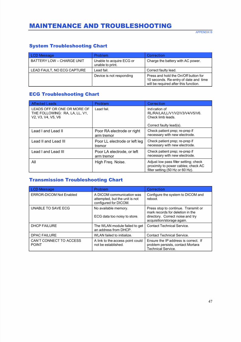
7/23/2019 Burdick ELI 250 User Manual
http://slidepdf.com/reader/full/burdick-eli-250-user-manual 69/72
MAINTENANCE AND TROUBLESHOOTING APPENDIX B
47
System Troubleshooting Chart
LCD Message Problem Correction
BATTERY LOW – CHARGE UNIT Unable to acquire ECG orunable to print.
Charge the battery with AC power.
LEAD FAULT, NO ECG CAPTURE Lead fail. Correct faulty lead.
Device is not responding Press and hold the On/Off button for10 seconds. Re-entry of date and timewill be required after this function.
ECG Troubleshooting Chart
Affected Leads Problem Correction
LEADS OFF OR ONE OR MORE OFTHE FOLLOWING: RA, LA, LL, V1,V2, V3, V4, V5, V6
Lead fail. Indication ofRL/RA/LA/LL/V1/V2/V3/V4/V5/V6.Check limb leads.
Correct faulty lead(s).
Lead I and Lead II Poor RA electrode or rightarm tremor
Check patient prep; re-prep ifnecessary with new electrode.
Lead II and Lead III Poor LL electrode or left legtremor
Check patient prep; re-prep ifnecessary with new electrode.
Lead I and Lead III Poor LA electrode, or leftarm tremor
Check patient prep; re-prep ifnecessary with new electrode.
All High Freq. Noise. Adjust low pass filter setting; checkproximity to power cables; check ACfilter setting (50 Hz or 60 Hz).
Transmission Troubleshooting Chart
LCD Message Problem Correction
ERROR-DICOM Not Enabled A DICOM communication wasattempted, but the unit is notconfigured for DICOM.
Configure the system to DICOM andreboot.
UNABLE TO SAVE ECG No available memory.
ECG data too noisy to store.
Press stop to continue. Transmit ormark records for deletion in thedirectory. Correct noise and tryacquisition/storage again.
DHCP FAILURE The WLAN module failed to getan address from DHCP.
Contact Technical Service.
DPAC FAILURE WLAN failed to initialize. Contact Technical Service.
CAN’T CONNECT TO ACCESSPOINT
A link to the access point couldnot be established.
Ensure the IP address is correct. Ifproblem persists, contact MortaraTechnical Service.
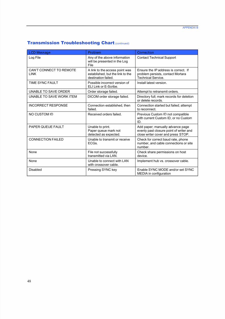
7/23/2019 Burdick ELI 250 User Manual
http://slidepdf.com/reader/full/burdick-eli-250-user-manual 70/72
APPENDIX B
48
Transmission Troubleshooting Chart (continued)
LCD Message Problem Correction
Log File Any of the above informationwill be presented in the LogFile
Contact Technical Support
CAN’T CONNECT TO REMOTELINK
A link to the access point wasestablished, but the link to thedestination failed.
Ensure the IP address is correct. Ifproblem persists, contact MortaraTechnical Service.
TIME SYNC FAULT Possible incorrect version ofELI Link or E-Scribe.
Install latest version.
UNABLE TO SAVE ORDER Order storage failed. Attempt to retransmit orders.
UNABLE TO SAVE WORK ITEM DICOM order storage failed. Directory full; mark records for deletionor delete records.
INCORRECT RESPONSE Connection established, thenfailed.
Connection started but failed; attemptto reconnect.
NO CUSTOM ID Received orders failed. Previous Custom ID not compatiblewith current Custom ID, or no CustomID.
PAPER QUEUE FAULT Unable to print.Paper queue mark notdetected as expected.
Add paper; manually advance pageevenly past closure point of writer andclose writer cover and press STOP.
CONNECTION FAILED Unable to transmit or receiveECGs.
Check for correct baud rate, phonenumber, and cable connections or sitenumber.
None File not successfullytransmitted via LAN.
Check share permissions on hostdevice.
None Unable to connect with LANwith crossover cable.
Implement hub vs. crossover cable.
Disabled Pressing SYNC key Enable SYNC MODE and/or set SYNCMEDIA in configuration

7/23/2019 Burdick ELI 250 User Manual
http://slidepdf.com/reader/full/burdick-eli-250-user-manual 71/72
APPENDIX B
49
Power Off the Device
To completely shutdown the device, disconnect the AC power cord then press the ON/OFF button. Such a
shutdown should always be performed prior to authorized repair of the device.
Test Operation
After cleaning and inspecting the device, proper operation of the unit may be confirmed by using an ECG simulatorto acquire and print a standard 12-lead ECG of known amplitude. Printing should be dark and even across the page.
There should be no evidence of print head dot failure (e.g., breaks in printing forming horizontal streaks). Paper
motion should be smooth and consistent during printing. Waveforms should appear normal with proper amplitude
and, without distortion or excessive noise. Paper should stop with perforations near the tear bar (indicating proper
cue sensor operation).
Recommendations to Biomedical Staff
Following any service to the device or when non-compliant operation is suspected, Mortara and Burdickrecommends the following procedures:
• Confirm proper operation.
• Perform testing to ensure continued electrical safety of the device
(use IEC 60601-1 or ANSI/AAMI ES1 methods and limits).
• patient leakage current
• chassis leakage current
• earth leakage current
• dielectric strength (mains and patient circuits)
Battery Maintenance
The device houses an internal, sealed lead-acid battery. When installed, the battery has a shelf life of approximatelysix months without recharging. If the battery has been stored for a long period in a discharged state, it may not be
able to regain its capacity even if it is recharged.
For information about replacing the battery, please refer to the device’s service manual.
Mortara recommends that the device be plugged into AC power whenever possible to maximize battery life and for
the user to develop a habit of recharging the battery before the unit indicates a “low battery” condition. (That is,
reduced depth of discharge.) Battery life varies by how the battery is maintained and how much it is used. Forimproved battery life, keep the electrocardiograph plugged in when not in use.
The sealed lead-acid battery will provide optimum life when the unit is fully charged after each use. When the
battery charge is depleted to its lowest level (10.6V), the device will automatically power down. To recharge a battery from its lowest level to 85%, 4 hours of recharging may be necessary. To reach 90%, 7 hours of recharging
may be necessary. It may take longer to reach 100%. The device can be used with AC power while simultaneously
charging.
7/23/2019 Burdick ELI 250 User Manual
http://slidepdf.com/reader/full/burdick-eli-250-user-manual 72/72
APPENDIX B
Cleaning the Thermal Printer
To clean the printer
1. Disconnect the power source.
2. Clean the exterior surface of the unit with a damp cloth using a solution of mild dishwashing detergent
diluted in water.
3. After washing, thoroughly dry off the unit with a clean, soft cloth or paper towel.
To clean the print head
NOTE: Do not let soap or water come into contact with the writer, plugs, jacks, or vents.
1. Open writer door.
2. Lightly rub print head with an alcohol pad.
3. Wipe with a clean cloth to remove alcohol residue.
4. Allow print head to air dry.
5. Clean the platen by using adhesive tape. Apply the tape and pull it off. Rotate roller and repeat until entire
roller is clean.
6. Clean cue sensor photo detector.