Embed Size (px)
Citation preview
ArcGIS®
9Building Geodatabases Tutorial
Copyright © 2006–2008 ESRIAll rights reserved.Printed in the United States of America.
The information contained in this document is the exclusive property of ESRI. This work is protected under United States copyright law and other international copyrighttreaties and conventions. No part of this work may be reproduced or transmitted in any form or by any means, electronic or mechanical, including photocopying andrecording, or by any information storage or retrieval system, except as expressly permitted in writing by ESRI. All requests should be sent to Attention: ContractsManager, ESRI, 380 New York Street, Redlands, CA 92373-8100, USA.
The information contained in this document is subject to change without notice.
DATA CREDITS
Creating Topology Tutorial Data: U.S. Geological Survey in cooperation with U.S. Environmental Protection Agency, National Hydrography Dataset
CONTRIBUTING WRITERSBob Booth, Andy MacDonald
U.S. GOVERNMENT RESTRICTED/LIMITED RIGHTSAny software, documentation, and/or data delivered hereunder is subject to the terms of the License Agreement. In no event shall the U.S. Government acquire greaterthan RESTRICTED/LIMITED RIGHTS. At a minimum, use, duplication, or disclosure by the U.S. Government is subject to restrictions as set forth in FAR §52.227-14Alternates I, II, and III (JUN 1987); FAR §52.227-19 (JUN 1987) and/or FAR §12.211/12.212 (Commercial Technical Data/Computer Software); and DFARS §252.227-7015 (NOV 1995) (Technical Data) and/or DFARS §227.7202 (Computer Software), as applicable. Contractor/Manufacturer is ESRI, 380 New York Street, Redlands,CA 92373-8100, USA.
ESRI, ArcView, the ESRI globe logo, ArcGIS, ArcMap, ArcCatalog, ArcEditor, ArcInfo, the ArcGIS logo, Geography Network, ArcSDE, SDE, Spatial Database Engine,GIS by ESRI, and www.esri.com are trademarks, registered trademarks, or service marks of ESRI in the United States, the European Community, or certain otherjurisdictions.
Other companies and products mentioned herein are trademarks or registered trademarks of their respective trademark owners.
$WWULEXWLRQ�SPG ����������������30�
IN THIS TUTORIAL
1
Building Geodatabases Tutorial
• Exercise 1: Organizing your datain ArcCatalog
• Exercise 2: Importing data intoyour geodatabase
• Exercise 3: Creating subtypes andattribute domains
• Exercise 4: Creating relationshipsbetween objects
• Exercise 5: Building a geometricnetwork
• Exercise 6: Creating annotation
• Exercise 7: Creating layers foryour geodatabase data
• Exercise 8: Creating a topology
• Exercise 9: Loading coverage datainto a geodatabase topology
It is easy to create a geodatabase and add behavior to it, and it requires noprogramming when you use the data management tools in ArcCatalog—theapplication for browsing, storing, organizing, and distributing data. Whenquerying and editing the geodatabase in ArcMap—the application forediting, analyzing, and creating maps from your data—you can easily takeadvantage of the data and behavior in your geodatabase without anycustomization.
This tutorial lets you explore the capabilities of the geodatabase using anArcEditor or ArcInfo licensed seat of ArcCatalog and ArcMap. You cancomplete this tutorial at your own pace without the need for additionalassistance. This tutorial includes nine exercises. Each exercise takesbetween 10 and 20 minutes to complete.
In the first eight exercises of this tutorial, you will use ArcCatalog to createa geodatabase that models a water utility network. You will add behavior tothe geodatabase by creating subtypes, validation rules, relationships, and ageometric network. You can use ArcMap to take advantage of the behaviorby editing some of the existing features in the geodatabase and adding someadditional features.
The study area for the first eight exercises is a portion of a hypothetical city.A geodatabase that contains most of the data, a coverage representing waterlaterals, and an INFO™ table representing parcel owner data are providedwith the software. You will import the coverage and INFO table into thegeodatabase, then modify its properties to give it behavior.
Ch04.pmd 5/11/2006, 3:51 PM1
2 BUILDING GEODATABASES TUTORIAL
In the last exercise, you will take coverages and importselected feature classes into a new geodatabase. The studyarea for the last exercise is a portion of a drainage basin inUtah.
The datasets for the first eight exercises were created byESRI using a database schema similar to that of the city ofMontgomery, Alabama. The data is wholly fictitious andhas nothing to do with the actual city of Montgomery. Thisinformation may be updated, corrected, or otherwisemodified without notification.
The data for the last exercise on loading coverage data intoa geodatabase topology is from the National HydrographyDataset, published by the USGS in cooperation with theEPA, Utah AGRC, and REDCON. The watershed coverage,basin_utm, was fabricated for this exercise. Thisinformation may be updated, corrected, or otherwisemodified without notification.
Ch04.pmd 5/11/2006, 3:51 PM2
3
Exercise 1: Organizing your data in ArcCatalog
Before you begin the tutorial, you must find and organizethe data that you will need. This can be done usingArcCatalog.
Connecting to data
In ArcCatalog, data is accessed through folder connections.When you look in a folder connection, you can quickly seethe folders and data sources it contains. You will now beginorganizing your data by creating a folder connection to it.
1. Start ArcCatalog by either double-clicking a shortcutinstalled on your desktop or using the Programs list inyour Start menu.
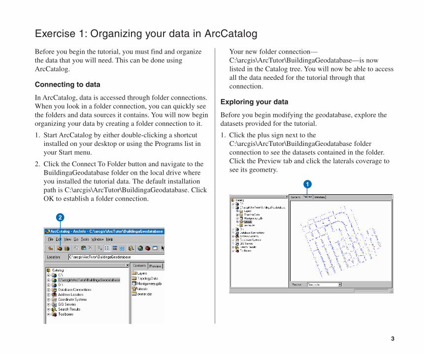
2. Click the Connect To Folder button and navigate to theBuildingaGeodatabase folder on the local drive whereyou installed the tutorial data. The default installationpath is C:\arcgis\ArcTutor\BuildingaGeodatabase. ClickOK to establish a folder connection.
Your new folder connection—C:\arcgis\ArcTutor\BuildingaGeodatabase—is nowlisted in the Catalog tree. You will now be able to accessall the data needed for the tutorial through thatconnection.
Exploring your data
Before you begin modifying the geodatabase, explore thedatasets provided for the tutorial.
1. Click the plus sign next to theC:\arcgis\ArcTutor\BuildingaGeodatabase folderconnection to see the datasets contained in the folder.Click the Preview tab and click the laterals coverage tosee its geometry.
1
2
Ch04.pmd 5/11/2006, 3:51 PM3
4 BUILDING GEODATABASES TUTORIAL
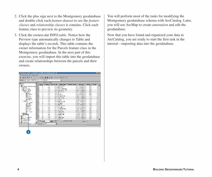
2. Click the plus sign next to the Montgomery geodatabaseand double-click each feature dataset to see the featureclasses and relationship classes it contains. Click eachfeature class to preview its geometry.
3. Click the owners.dat INFO table. Notice how thePreview type automatically changes to Table anddisplays the table’s records. This table contains theowner information for the Parcels feature class in theMontgomery geodatabase. In the next part of thisexercise, you will import this table into the geodatabaseand create relationships between the parcels and theirowners.
You will perform most of the tasks for modifying theMontgomery geodatabase schema with ArcCatalog. Later,you will use ArcMap to create annotation and edit thegeodatabase.
Now that you have found and organized your data inArcCatalog, you are ready to start the first task in thetutorial—importing data into the geodatabase.
3
Ch04.pmd 5/11/2006, 3:51 PM4
5
Exercise 2: Importing data into your geodatabase
Before you can start adding behavior to your data, youmust get it into a geodatabase. You will import two datasetsinto the Montgomery geodatabase—laterals and owner.dat.The laterals coverage contains water laterals for theMontgomery water dataset, and the owner.dat INFO tablecontains owner information for the parcel features alreadyin the geodatabase.
Importing the coverage
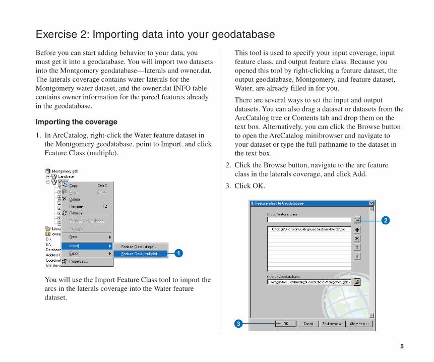
1. In ArcCatalog, right-click the Water feature dataset inthe Montgomery geodatabase, point to Import, and clickFeature Class (multiple).
You will use the Import Feature Class tool to import thearcs in the laterals coverage into the Water featuredataset.
This tool is used to specify your input coverage, inputfeature class, and output feature class. Because youopened this tool by right-clicking a feature dataset, theoutput geodatabase, Montgomery, and feature dataset,Water, are already filled in for you.
There are several ways to set the input and outputdatasets. You can also drag a dataset or datasets from theArcCatalog tree or Contents tab and drop them on thetext box. Alternatively, you can click the Browse buttonto open the ArcCatalog minibrowser and navigate toyour dataset or type the full pathname to the dataset inthe text box.
2. Click the Browse button, navigate to the arc featureclass in the laterals coverage, and click Add.
3. Click OK.
2
3
1
Ch04.pmd 5/11/2006, 3:51 PM5
6 BUILDING GEODATABASES TUTORIAL
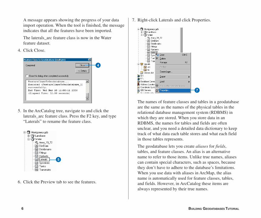
A message appears showing the progress of your dataimport operation. When the tool is finished, the messageindicates that all the features have been imported.
The laterals_arc feature class is now in the Waterfeature dataset.
4. Click Close.
5. In the ArcCatalog tree, navigate to and click thelaterals_arc feature class. Press the F2 key, and type“Laterals” to rename the feature class.
6. Click the Preview tab to see the features.
7. Right-click Laterals and click Properties.
The names of feature classes and tables in a geodatabaseare the same as the names of the physical tables in therelational database management system (RDBMS) inwhich they are stored. When you store data in anRDBMS, the names for tables and fields are oftenunclear, and you need a detailed data dictionary to keeptrack of what data each table stores and what each fieldin those tables represents.
The geodatabase lets you create aliases for fields,tables, and feature classes. An alias is an alternativename to refer to those items. Unlike true names, aliasescan contain special characters, such as spaces, becausethey don’t have to adhere to the database’s limitations.When you use data with aliases in ArcMap, the aliasname is automatically used for feature classes, tables,and fields. However, in ArcCatalog these items arealways represented by their true names.
7
4
5
Ch04.pmd 5/11/2006, 3:51 PM6
7
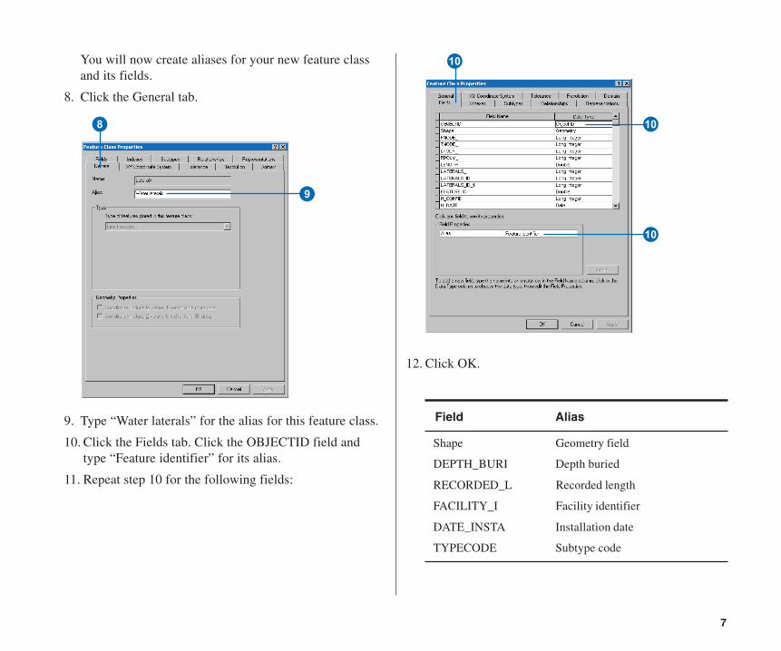
12. Click OK.
You will now create aliases for your new feature classand its fields.
8. Click the General tab.
9. Type “Water laterals” for the alias for this feature class.
10. Click the Fields tab. Click the OBJECTID field andtype “Feature identifier” for its alias.
11. Repeat step 10 for the following fields:
Field Alias
Shape Geometry field
DEPTH_BURI Depth buried
RECORDED_L Recorded length
FACILITY_I Facility identifier
DATE_INSTA Installation date
TYPECODE Subtype code
8
9
Q
Q
Q
Ch04.pmd 5/11/2006, 3:51 PM7
8 BUILDING GEODATABASES TUTORIAL
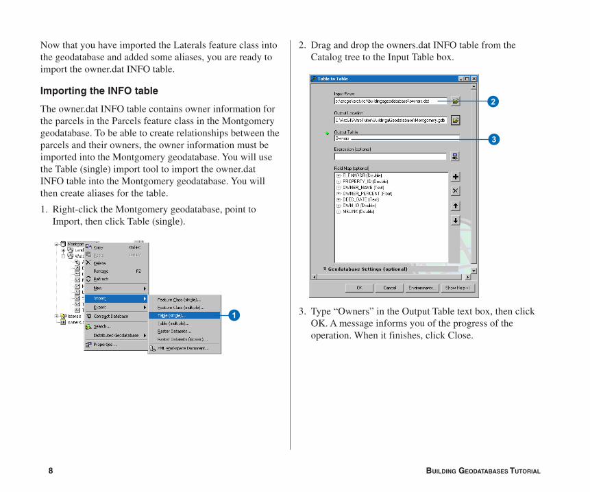
Now that you have imported the Laterals feature class intothe geodatabase and added some aliases, you are ready toimport the owner.dat INFO table.
Importing the INFO table
The owner.dat INFO table contains owner information forthe parcels in the Parcels feature class in the Montgomerygeodatabase. To be able to create relationships between theparcels and their owners, the owner information must beimported into the Montgomery geodatabase. You will usethe Table (single) import tool to import the owner.datINFO table into the Montgomery geodatabase. You willthen create aliases for the table.
1. Right-click the Montgomery geodatabase, point toImport, then click Table (single).
3. Type “Owners” in the Output Table text box, then clickOK. A message informs you of the progress of theoperation. When it finishes, click Close.
1
2. Drag and drop the owners.dat INFO table from theCatalog tree to the Input Table box.
2
3
Ch04.pmd 5/11/2006, 3:51 PM8
9
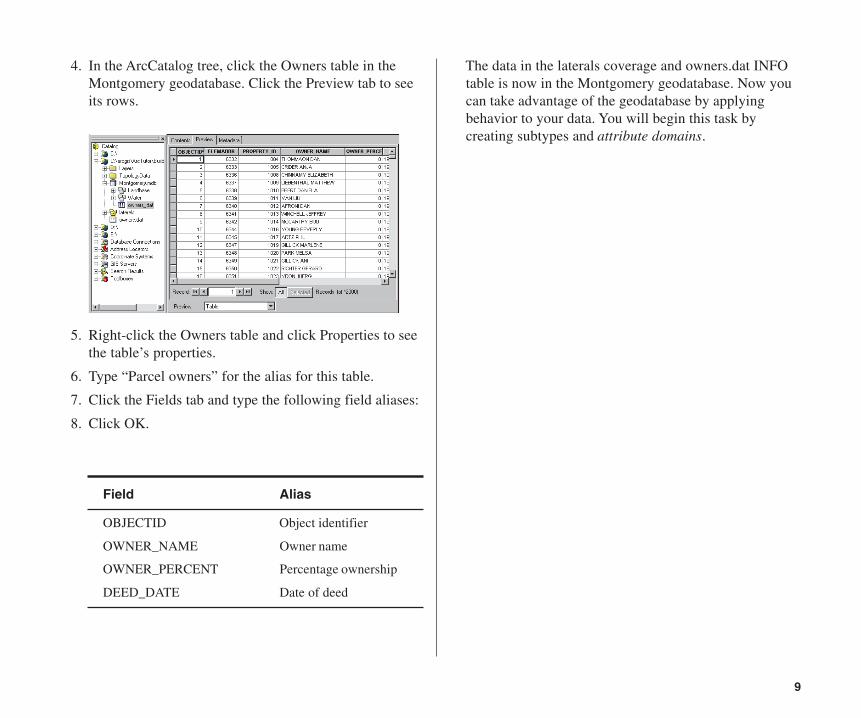
Field Alias
OBJECTID Object identifier
OWNER_NAME Owner name
OWNER_PERCENT Percentage ownership
DEED_DATE Date of deed
4. In the ArcCatalog tree, click the Owners table in theMontgomery geodatabase. Click the Preview tab to seeits rows.
5. Right-click the Owners table and click Properties to seethe table’s properties.
6. Type “Parcel owners” for the alias for this table.
7. Click the Fields tab and type the following field aliases:
8. Click OK.
The data in the laterals coverage and owners.dat INFOtable is now in the Montgomery geodatabase. Now youcan take advantage of the geodatabase by applyingbehavior to your data. You will begin this task bycreating subtypes and attribute domains.
Ch04.pmd 5/11/2006, 3:51 PM9
10 BUILDING GEODATABASES TUTORIAL
Exercise 3: Creating subtypes and attribute domains
One of the advantages of storing your data in a geodatabaseis that you can define rules about how the data can beedited. You will define these rules by creating a newattribute domain for lateral diameters; creating subtypes forthe Laterals feature class; and associating the new domain,existing domains, and default values with fields for eachsubtype.
Attribute domains are rules that describe the legal values ofa field type. Multiple feature classes and tables can shareattribute domains stored in the database. However, not allthe objects in a feature class or table need to share the sameattribute domains.
For example, in a water network, suppose that only hydrantwater laterals can have a pressure between 40 and 100 psi,while service water laterals can have a pressure between50 and 75 psi. You would use an attribute domain toenforce this restriction. To implement this kind ofvalidation rule, you do not have to create separate featureclasses for hydrant and service water laterals, but youwould want to distinguish these types of water laterals fromeach other to establish a separate set of domains anddefault values. You can do this using subtypes.
To learn more about subtypes and attribute domains, seethe topics on subtypes and attribute domains in the ArcGISDesktop Help.
Creating an attribute domain
You will use ArcCatalog to create a new coded valueattribute domain. This new domain will describe a set ofvalid pipe diameters for your new Laterals feature class.
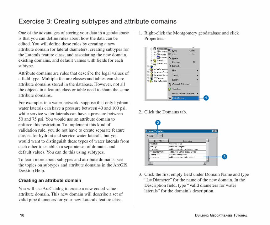
1. Right-click the Montgomery geodatabase and clickProperties.
2. Click the Domains tab.
3. Click the first empty field under Domain Name and type“LatDiameter” for the name of the new domain. In theDescription field, type “Valid diameters for waterlaterals” for the domain’s description.
2
3
1
Ch04.pmd 5/11/2006, 3:51 PM10
11
You will now specify the properties of the domain.These properties include the type of field this domaincan be associated with, the type of domain it is—rangeor coded value, the split and merge policies, and thevalid values for the domain.
A range domain describes a valid range of numericvalues, and a coded value domain describes a set ofvalid values. In this case, you will create a new codedvalue domain.
All domains also have split and merge policies. When afeature is split or merged, ArcGIS looks to these policiesto determine the values of the resulting feature orfeatures for a particular attribute.
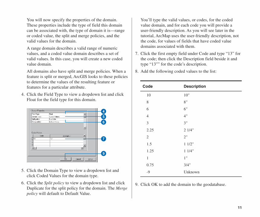
4. Click the Field Type to view a dropdown list and clickFloat for the field type for this domain.
5. Click the Domain Type to view a dropdown list andclick Coded Values for the domain type.
6. Click the Split policy to view a dropdown list and clickDuplicate for the split policy for the domain. The Mergepolicy will default to Default Value.
You’ll type the valid values, or codes, for the codedvalue domain, and for each code you will provide auser-friendly description. As you will see later in thetutorial, ArcMap uses the user-friendly description, notthe code, for values of fields that have coded valuedomains associated with them.
7. Click the first empty field under Code and type “13” forthe code; then click the Description field beside it andtype “13"” for the code’s description.
8. Add the following coded values to the list:
Code Description
10 10"
8 8"
6 6"
4 4"
3 3"
2.25 2 1/4"
2 2"
1.5 1 1/2"
1.25 1 1/4"
1 1"
0.75 3/4"
-9 Unknown
9. Click OK to add the domain to the geodatabase.
7
456
9
Ch04.pmd 5/11/2006, 3:51 PM11
12 BUILDING GEODATABASES TUTORIAL
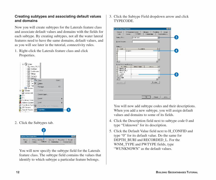
Creating subtypes and associating default valuesand domains
Now you will create subtypes for the Laterals feature classand associate default values and domains with the fields foreach subtype. By creating subtypes, not all the water lateralfeatures need to have the same domains, default values, andas you will see later in the tutorial, connectivity rules.
1. Right-click the Laterals feature class and clickProperties.
2. Click the Subtypes tab.
You will now specify the subtype field for the Lateralsfeature class. The subtype field contains the values thatidentify to which subtype a particular feature belongs.
3. Click the Subtype Field dropdown arrow and clickTYPECODE.
You will now add subtype codes and their descriptions.When you add a new subtype, you will assign defaultvalues and domains to some of its fields.
4. Click the Description field next to subtype code 0 andtype “Unknown” for its description.
5. Click the Default Value field next to H_CONFID andtype “0” for its default value. Do the same forDEPTH_BURI and RECORDED_L. For theWNM_TYPE and PWTYPE fields, type“WUNKNOWN” as the default values.
3
4
5
1
2
Ch04.pmd 5/11/2006, 3:51 PM12
13
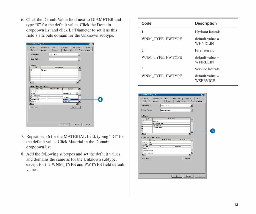
6. Click the Default Value field next to DIAMETER andtype “8” for the default value. Click the Domaindropdown list and click LatDiameter to set it as thisfield’s attribute domain for the Unknown subtype.
7. Repeat step 6 for the MATERIAL field, typing “DI” forthe default value. Click Material in the Domaindropdown list.
8. Add the following subtypes and set the default valuesand domains the same as for the Unknown subtype,except for the WNM_TYPE and PWTYPE field defaultvalues.
Code Description
1 Hydrant laterals
WNM_TYPE, PWTYPE default value =WHYDLIN
2 Fire laterals
WNM_TYPE, PWTYPE default value =WFIRELIN
3 Service laterals
WNM_TYPE, PWTYPE default value =WSERVICE
6
8
Ch04.pmd 5/11/2006, 3:51 PM13
14 BUILDING GEODATABASES TUTORIAL
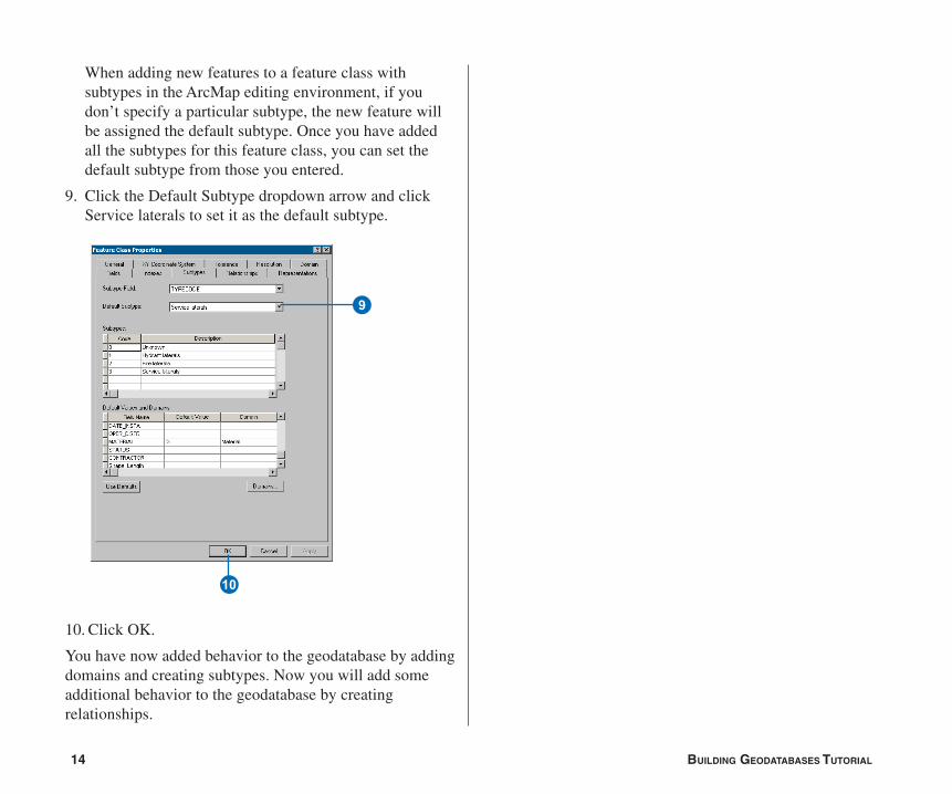
When adding new features to a feature class withsubtypes in the ArcMap editing environment, if youdon’t specify a particular subtype, the new feature willbe assigned the default subtype. Once you have addedall the subtypes for this feature class, you can set thedefault subtype from those you entered.
9. Click the Default Subtype dropdown arrow and clickService laterals to set it as the default subtype.
10. Click OK.
You have now added behavior to the geodatabase by addingdomains and creating subtypes. Now you will add someadditional behavior to the geodatabase by creatingrelationships.
Q
9
Ch04.pmd 5/11/2006, 3:51 PM14
15
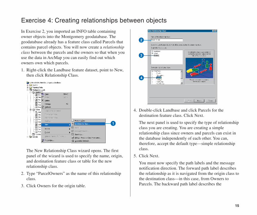
Exercise 4: Creating relationships between objects
In Exercise 2, you imported an INFO table containingowner objects into the Montgomery geodatabase. Thegeodatabase already has a feature class called Parcels thatcontains parcel objects. You will now create a relationshipclass between the parcels and the owners so that when youuse the data in ArcMap you can easily find out whichowners own which parcels.
1. Right-click the Landbase feature dataset, point to New,then click Relationship Class.
The New Relationship Class wizard opens. The firstpanel of the wizard is used to specify the name, origin,and destination feature class or table for the newrelationship class.
2. Type “ParcelOwners” as the name of this relationshipclass.
3. Click Owners for the origin table.
4. Double-click Landbase and click Parcels for thedestination feature class. Click Next.
The next panel is used to specify the type of relationshipclass you are creating. You are creating a simplerelationship class since owners and parcels can exist inthe database independently of each other. You can,therefore, accept the default type—simple relationshipclass.
5. Click Next.
You must now specify the path labels and the messagenotification direction. The forward path label describesthe relationship as it is navigated from the origin class tothe destination class—in this case, from Owners toParcels. The backward path label describes the
1
3
4
2
Ch04.pmd 5/11/2006, 3:51 PM15
16 BUILDING GEODATABASES TUTORIAL
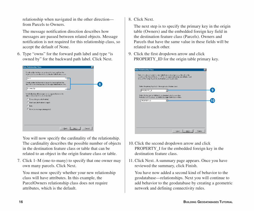
relationship when navigated in the other direction—from Parcels to Owners.
The message notification direction describes howmessages are passed between related objects. Messagenotification is not required for this relationship class, soaccept the default of None.
6. Type “owns” for the forward path label and type “isowned by” for the backward path label. Click Next.
You will now specify the cardinality of the relationship.The cardinality describes the possible number of objectsin the destination feature class or table that can berelated to an object in the origin feature class or table.
7. Click 1–M (one-to-many) to specify that one owner mayown many parcels. Click Next.
You must now specify whether your new relationshipclass will have attributes. In this example, theParcelOwners relationship class does not requireattributes, which is the default.
8. Click Next.
The next step is to specify the primary key in the origintable (Owners) and the embedded foreign key field inthe destination feature class (Parcels). Owners andParcels that have the same value in these fields will berelated to each other.
9. Click the first dropdown arrow and clickPROPERTY_ID for the origin table primary key.
10. Click the second dropdown arrow and clickPROPERTY_I for the embedded foreign key in thedestination feature class.
11. Click Next. A summary page appears. Once you havereviewed the summary, click Finish.
You have now added a second kind of behavior to thegeodatabase—relationships. Next you will continue toadd behavior to the geodatabase by creating a geometricnetwork and defining connectivity rules.
69
Q
Ch04.pmd 5/11/2006, 3:51 PM16
17
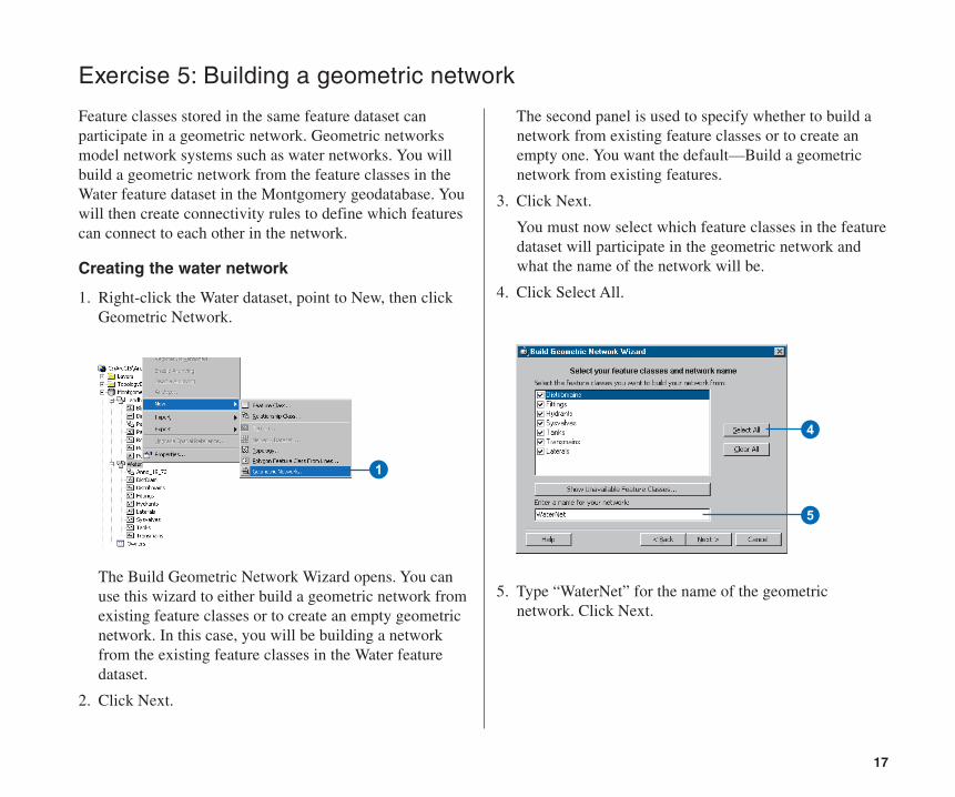
Exercise 5: Building a geometric network
Feature classes stored in the same feature dataset canparticipate in a geometric network. Geometric networksmodel network systems such as water networks. You willbuild a geometric network from the feature classes in theWater feature dataset in the Montgomery geodatabase. Youwill then create connectivity rules to define which featurescan connect to each other in the network.
Creating the water network
1. Right-click the Water dataset, point to New, then clickGeometric Network.
The Build Geometric Network Wizard opens. You canuse this wizard to either build a geometric network fromexisting feature classes or to create an empty geometricnetwork. In this case, you will be building a networkfrom the existing feature classes in the Water featuredataset.
2. Click Next.
The second panel is used to specify whether to build anetwork from existing feature classes or to create anempty one. You want the default—Build a geometricnetwork from existing features.
3. Click Next.
You must now select which feature classes in the featuredataset will participate in the geometric network andwhat the name of the network will be.
4. Click Select All.
5. Type “WaterNet” for the name of the geometricnetwork. Click Next.
1
4
5
Ch04.pmd 5/11/2006, 3:51 PM17
18 BUILDING GEODATABASES TUTORIAL
The option to exclude features with certain attributesmakes it easier to manage the state of parts of thenetwork if you need to drop the network and rebuild itafter you’ve been working with it for a while.
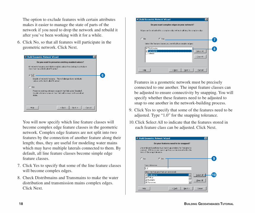
6. Click No, so that all features will participate in thegeometric network. Click Next.
You will now specify which line feature classes willbecome complex edge feature classes in the geometricnetwork. Complex edge features are not split into twofeatures by the connection of another feature along theirlength; thus, they are useful for modeling water mainswhich may have multiple laterals connected to them. Bydefault, all line feature classes become simple edgefeature classes.
7. Click Yes to specify that some of the line feature classeswill become complex edges.
8. Check Distribmains and Transmains to make the waterdistribution and transmission mains complex edges.Click Next.
Features in a geometric network must be preciselyconnected to one another. The input feature classes canbe adjusted to ensure connectivity by snapping. You willspecify whether these features need to be adjusted tosnap to one another in the network-building process.
9. Click Yes to specify that some of the features need to beadjusted. Type “1.0” for the snapping tolerance.
10. Click Select All to indicate that the features stored ineach feature class can be adjusted. Click Next.
8
6
7
Q
9
Ch04.pmd 5/11/2006, 3:51 PM18
19
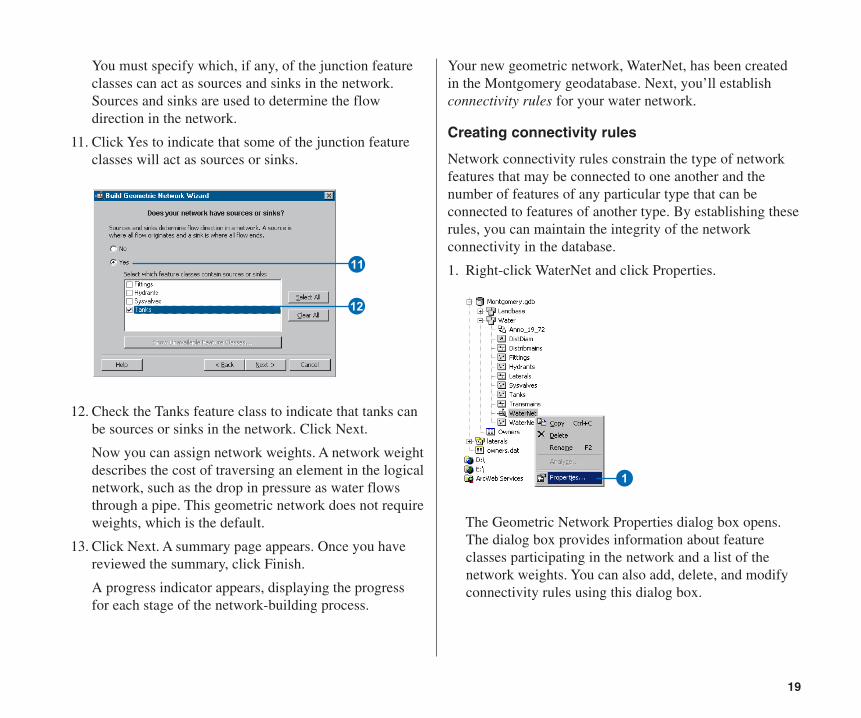
You must specify which, if any, of the junction featureclasses can act as sources and sinks in the network.Sources and sinks are used to determine the flowdirection in the network.
11. Click Yes to indicate that some of the junction featureclasses will act as sources or sinks.
12. Check the Tanks feature class to indicate that tanks canbe sources or sinks in the network. Click Next.
Now you can assign network weights. A network weightdescribes the cost of traversing an element in the logicalnetwork, such as the drop in pressure as water flowsthrough a pipe. This geometric network does not requireweights, which is the default.
13. Click Next. A summary page appears. Once you havereviewed the summary, click Finish.
A progress indicator appears, displaying the progressfor each stage of the network-building process.
Your new geometric network, WaterNet, has been createdin the Montgomery geodatabase. Next, you’ll establishconnectivity rules for your water network.
Creating connectivity rules
Network connectivity rules constrain the type of networkfeatures that may be connected to one another and thenumber of features of any particular type that can beconnected to features of another type. By establishing theserules, you can maintain the integrity of the networkconnectivity in the database.
1. Right-click WaterNet and click Properties.
The Geometric Network Properties dialog box opens.The dialog box provides information about featureclasses participating in the network and a list of thenetwork weights. You can also add, delete, and modifyconnectivity rules using this dialog box.
1
E
W
Ch04.pmd 5/11/2006, 3:51 PM19
20 BUILDING GEODATABASES TUTORIAL
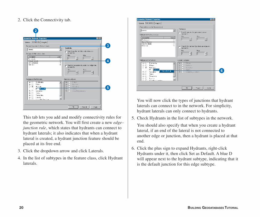
2. Click the Connectivity tab.
This tab lets you add and modify connectivity rules forthe geometric network. You will first create a new edge–junction rule, which states that hydrants can connect tohydrant laterals; it also indicates that when a hydrantlateral is created, a hydrant junction feature should beplaced at its free end.
3. Click the dropdown arrow and click Laterals.
4. In the list of subtypes in the feature class, click Hydrantlaterals.
You will now click the types of junctions that hydrantlaterals can connect to in the network. For simplicity,hydrant laterals can only connect to hydrants.
5. Check Hydrants in the list of subtypes in the network.
You should also specify that when you create a hydrantlateral, if an end of the lateral is not connected toanother edge or junction, then a hydrant is placed at thatend.
6. Click the plus sign to expand Hydrants, right-clickHydrants under it, then click Set as Default. A blue Dwill appear next to the hydrant subtype, indicating that itis the default junction for this edge subtype.
6
2
5
3
4
Ch04.pmd 5/11/2006, 3:51 PM20
21
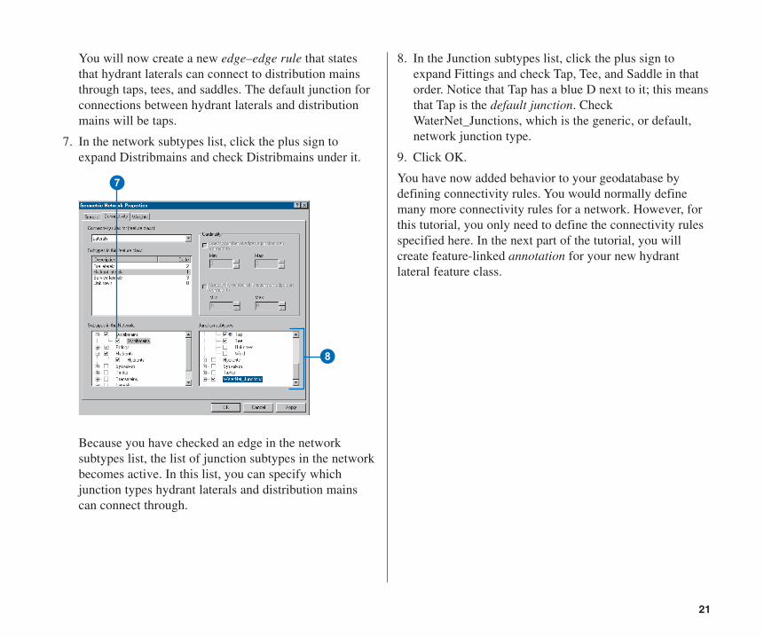
You will now create a new edge–edge rule that statesthat hydrant laterals can connect to distribution mainsthrough taps, tees, and saddles. The default junction forconnections between hydrant laterals and distributionmains will be taps.
7. In the network subtypes list, click the plus sign toexpand Distribmains and check Distribmains under it.
Because you have checked an edge in the networksubtypes list, the list of junction subtypes in the networkbecomes active. In this list, you can specify whichjunction types hydrant laterals and distribution mainscan connect through.
8
7
8. In the Junction subtypes list, click the plus sign toexpand Fittings and check Tap, Tee, and Saddle in thatorder. Notice that Tap has a blue D next to it; this meansthat Tap is the default junction. CheckWaterNet_Junctions, which is the generic, or default,network junction type.
9. Click OK.
You have now added behavior to your geodatabase bydefining connectivity rules. You would normally definemany more connectivity rules for a network. However, forthis tutorial, you only need to define the connectivity rulesspecified here. In the next part of the tutorial, you willcreate feature-linked annotation for your new hydrantlateral feature class.
Ch04.pmd 5/11/2006, 3:51 PM21

22 BUILDING GEODATABASES TUTORIAL
Exercise 6: Creating annotation
In Exercise 1, you browsed through the existing featureclasses in the Montgomery geodatabase. One of thesefeature classes contained annotation that was linked tofeatures in the Distribmains feature classes. You thenimported the water laterals from a coverage into the Waterfeature dataset. Now you will create labels for the waterlaterals in ArcMap and convert them to an annotationfeature class that is linked to the laterals.
Creating labels for the lateral subtypes
You’ll start ArcMap and add the Laterals feature class.
1. Click the Launch ArcMap button. Start a new, emptymap document.
2. Click the Laterals feature class, drag it from ArcCatalog,and drop it on the ArcMap table of contents.
1
2
Because you created subtypes for the Laterals featureclass, each subtype is automatically drawn with uniquesymbols. You’ll create different label classes for thesubtypes.
3. In ArcMap, right-click Laterals and click Properties.
4. Click the Labels tab.
5. Check the box to Label features in this layer.
6. Click the Method dropdown list and click Define classesof features and label each class differently.
7. Click Get Symbol Classes.
Now the layer has several label classes defined—one foreach subtype and one for other values.
3
45
6
7
Ch04.pmd 5/11/2006, 3:51 PM22
23
Defining the labels for the hydrant laterals
The different subtypes of laterals have different roles in thewater system. For example, service laterals bring waterfrom the distribution mains to residences or businesses, andhydrant laterals bring water from mains to fire hydrants.You will make the labels for the hydrant laterals red tomake it easy for map readers to differentiate hydrantlaterals from other laterals.
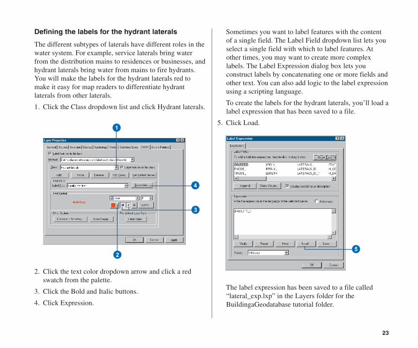
1. Click the Class dropdown list and click Hydrant laterals.
2. Click the text color dropdown arrow and click a redswatch from the palette.
3. Click the Bold and Italic buttons.
4. Click Expression.
1
2
3
4
Sometimes you want to label features with the contentof a single field. The Label Field dropdown list lets youselect a single field with which to label features. Atother times, you may want to create more complexlabels. The Label Expression dialog box lets youconstruct labels by concatenating one or more fields andother text. You can also add logic to the label expressionusing a scripting language.
To create the labels for the hydrant laterals, you’ll load alabel expression that has been saved to a file.
5. Click Load.
The label expression has been saved to a file called“lateral_exp.lxp” in the Layers folder for theBuildingaGeodatabase tutorial folder.
5
Ch04.pmd 5/11/2006, 3:51 PM23
24 BUILDING GEODATABASES TUTORIAL
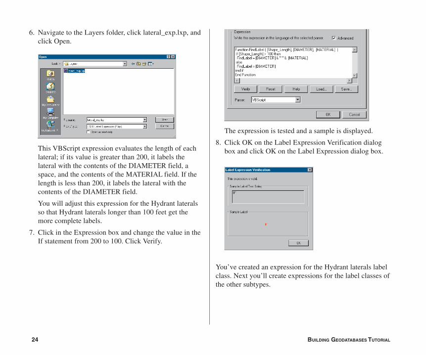
6. Navigate to the Layers folder, click lateral_exp.lxp, andclick Open.
This VBScript expression evaluates the length of eachlateral; if its value is greater than 200, it labels thelateral with the contents of the DIAMETER field, aspace, and the contents of the MATERIAL field. If thelength is less than 200, it labels the lateral with thecontents of the DIAMETER field.
You will adjust this expression for the Hydrant lateralsso that Hydrant laterals longer than 100 feet get themore complete labels.
7. Click in the Expression box and change the value in theIf statement from 200 to 100. Click Verify.
The expression is tested and a sample is displayed.
8. Click OK on the Label Expression Verification dialogbox and click OK on the Label Expression dialog box.
You’ve created an expression for the Hydrant laterals labelclass. Next you’ll create expressions for the label classes ofthe other subtypes.
Ch04.pmd 5/11/2006, 3:51 PM24
25
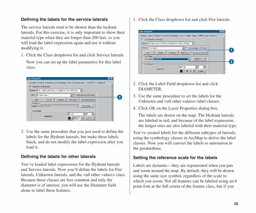
Defining the labels for the service laterals
The service laterals tend to be shorter than the hydrantlaterals. For this exercise, it is only important to show theirmaterial type when they are longer than 200 feet, so youwill load the label expression again and use it withoutmodifying it.
1. Click the Class dropdown list and click Service laterals.
Now you can set up the label parameters for this labelclass.
2. Use the same procedure that you just used to define thelabels for the Hydrant laterals, but make these labelsblack, and do not modify the label expression after youload it.
Defining the labels for other laterals
You’ve loaded label expressions for the Hydrant lateralsand Service laterals. Now you’ll define the labels for Firelaterals, Unknown laterals, and the <all other values> class.Because these classes are less common and only thediameter is of interest, you will use the Diameter fieldalone to label these features.
1
1. Click the Class dropdown list and click Fire laterals.
2. Click the Label Field dropdown list and clickDIAMETER.
3. Use the same procedure to set the labels for theUnknown and <all other values> label classes.
4. Click OK on the Layer Properties dialog box.
The labels are drawn on the map. The Hydrant lateralsare labeled in red, and because of the label expression,the longer ones are also labeled with their material type.
You’ve created labels for the different subtypes of laterals,using the symbology classes in ArcMap to derive the labelclasses. Now you will convert the labels to annotation inthe geodatabase.
Setting the reference scale for the labels
Labels are dynamic—they are regenerated when you panand zoom around the map. By default, they will be drawnusing the same size symbol, regardless of the scale towhich you zoom. Not all features can be labeled using an 8point font at the full extent of the feature class, but if you
1
2
Ch04.pmd 5/11/2006, 3:51 PM25
26 BUILDING GEODATABASES TUTORIAL
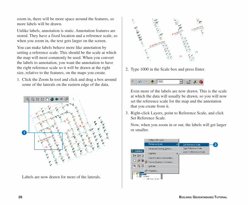
zoom in, there will be more space around the features, somore labels will be drawn.
Unlike labels, annotation is static. Annotation features arestored. They have a fixed location and a reference scale, sowhen you zoom in, the text gets larger on the screen.
You can make labels behave more like annotation bysetting a reference scale. This should be the scale at whichthe map will most commonly be used. When you convertthe labels to annotation, you want the annotation to havethe right reference scale so it will be drawn at the rightsize, relative to the features, on the maps you create.
1. Click the Zoom In tool and click and drag a box aroundsome of the laterals on the eastern edge of the data.
Labels are now drawn for more of the laterals.
1
2. Type 1000 in the Scale box and press Enter.
Even more of the labels are now drawn. This is the scaleat which the data will usually be drawn, so you will nowset the reference scale for the map and the annotationthat you create from it.
3. Right-click Layers, point to Reference Scale, and clickSet Reference Scale.
Now, when you zoom in or out, the labels will get largeror smaller.
3
Ch04.pmd 5/11/2006, 3:51 PM26
27
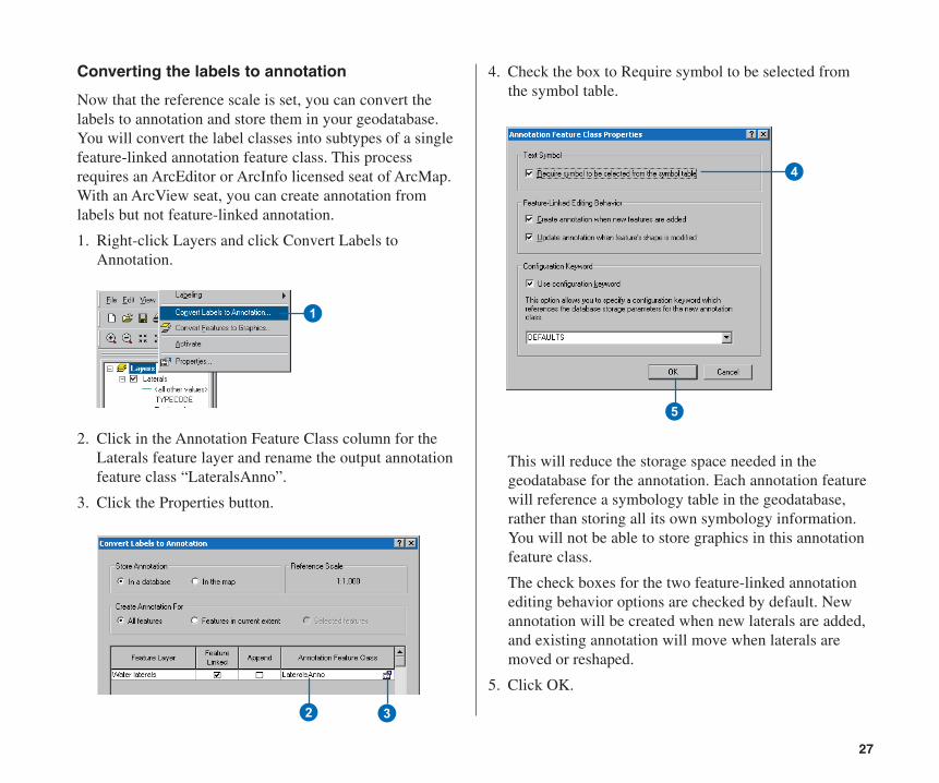
Converting the labels to annotation
Now that the reference scale is set, you can convert thelabels to annotation and store them in your geodatabase.You will convert the label classes into subtypes of a singlefeature-linked annotation feature class. This processrequires an ArcEditor or ArcInfo licensed seat of ArcMap.With an ArcView seat, you can create annotation fromlabels but not feature-linked annotation.
1. Right-click Layers and click Convert Labels toAnnotation.
2. Click in the Annotation Feature Class column for theLaterals feature layer and rename the output annotationfeature class “LateralsAnno”.
3. Click the Properties button.
1
4. Check the box to Require symbol to be selected fromthe symbol table.
This will reduce the storage space needed in thegeodatabase for the annotation. Each annotation featurewill reference a symbology table in the geodatabase,rather than storing all its own symbology information.You will not be able to store graphics in this annotationfeature class.
The check boxes for the two feature-linked annotationediting behavior options are checked by default. Newannotation will be created when new laterals are added,and existing annotation will move when laterals aremoved or reshaped.
5. Click OK.
4
5
2 3
Ch04.pmd 5/11/2006, 3:51 PM27
28 BUILDING GEODATABASES TUTORIAL
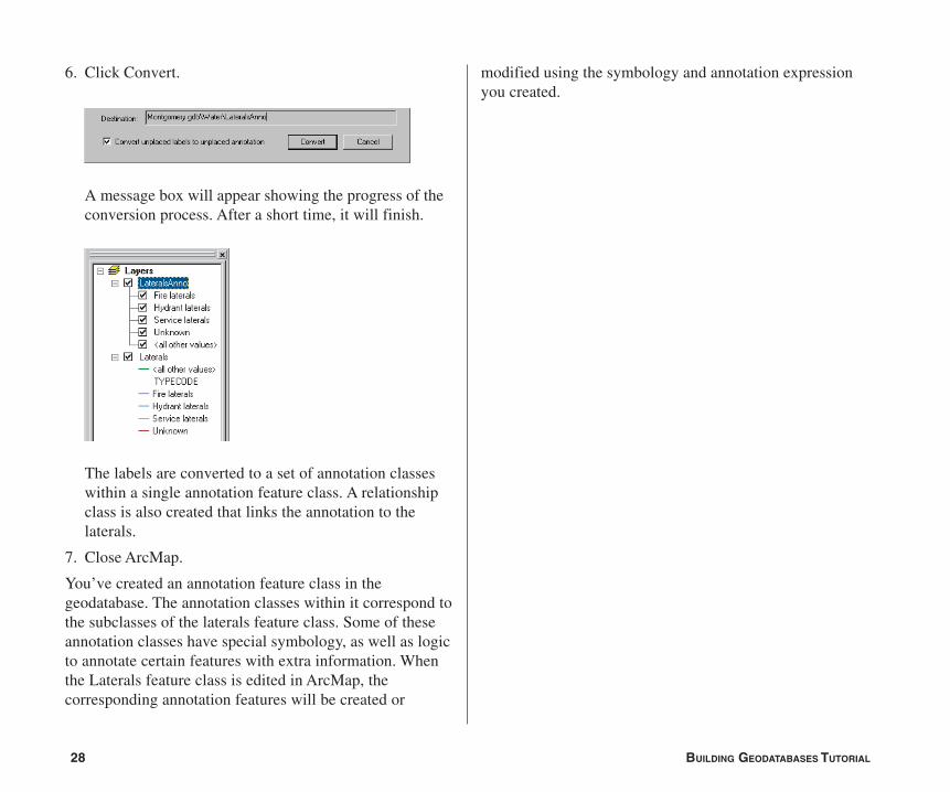
6. Click Convert.
A message box will appear showing the progress of theconversion process. After a short time, it will finish.
The labels are converted to a set of annotation classeswithin a single annotation feature class. A relationshipclass is also created that links the annotation to thelaterals.
7. Close ArcMap.
You’ve created an annotation feature class in thegeodatabase. The annotation classes within it correspond tothe subclasses of the laterals feature class. Some of theseannotation classes have special symbology, as well as logicto annotate certain features with extra information. Whenthe Laterals feature class is edited in ArcMap, thecorresponding annotation features will be created or
modified using the symbology and annotation expressionyou created.
Ch04.pmd 5/11/2006, 3:51 PM28
29
Exercise 7: Creating layers for your geodatabase data
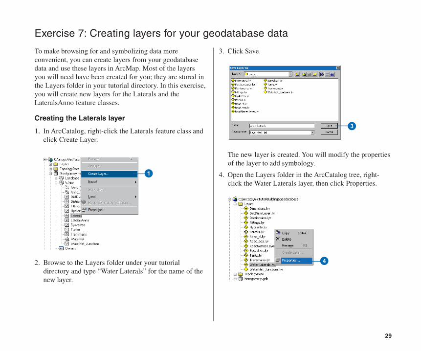
To make browsing for and symbolizing data moreconvenient, you can create layers from your geodatabasedata and use these layers in ArcMap. Most of the layersyou will need have been created for you; they are stored inthe Layers folder in your tutorial directory. In this exercise,you will create new layers for the Laterals and theLateralsAnno feature classes.
Creating the Laterals layer
1. In ArcCatalog, right-click the Laterals feature class andclick Create Layer.
2. Browse to the Layers folder under your tutorialdirectory and type “Water Laterals” for the name of thenew layer.
3. Click Save.
The new layer is created. You will modify the propertiesof the layer to add symbology.
4. Open the Layers folder in the ArcCatalog tree, right-click the Water Laterals layer, then click Properties.
3
1
4
Ch04.pmd 5/11/2006, 3:51 PM29
30 BUILDING GEODATABASES TUTORIAL
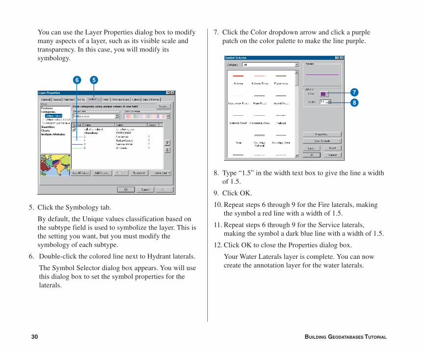
You can use the Layer Properties dialog box to modifymany aspects of a layer, such as its visible scale andtransparency. In this case, you will modify itssymbology.
5. Click the Symbology tab.
By default, the Unique values classification based onthe subtype field is used to symbolize the layer. This isthe setting you want, but you must modify thesymbology of each subtype.
6. Double-click the colored line next to Hydrant laterals.
The Symbol Selector dialog box appears. You will usethis dialog box to set the symbol properties for thelaterals.
7. Click the Color dropdown arrow and click a purplepatch on the color palette to make the line purple.
8. Type “1.5” in the width text box to give the line a widthof 1.5.
9. Click OK.
10. Repeat steps 6 through 9 for the Fire laterals, makingthe symbol a red line with a width of 1.5.
11. Repeat steps 6 through 9 for the Service laterals,making the symbol a dark blue line with a width of 1.5.
12. Click OK to close the Properties dialog box.
Your Water Laterals layer is complete. You can nowcreate the annotation layer for the water laterals.
56
78
Ch04.pmd 5/11/2006, 3:51 PM30
31
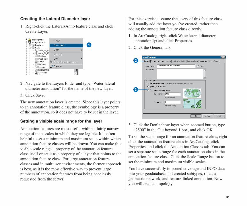
Creating the Lateral Diameter layer
1. Right-click the LateralsAnno feature class and clickCreate Layer.
2. Navigate to the Layers folder and type “Water lateraldiameter annotation” for the name of the new layer.
3. Click Save.
The new annotation layer is created. Since this layer pointsto an annotation feature class, the symbology is a propertyof the annotation, so it does not have to be set in the layer.
Setting a visible scale range for the layer
Annotation features are most useful within a fairly narrowrange of map scales in which they are legible. It is oftenhelpful to set a minimum and maximum scale within whichannotation feature classes will be drawn. You can make thisvisible scale range a property of the annotation featureclass itself or set it as a property of a layer that points to theannotation feature class. For large annotation featureclasses and in multiuser environments, the former approachis best, as it is the most effective way to prevent largenumbers of annotation features from being needlesslyrequested from the server.
1
For this exercise, assume that users of this feature classwill usually add the layer you’ve created, rather thanadding the annotation feature class directly.
1. In ArcCatalog, right-click Water lateral diameterannotation.lyr and click Properties.
2. Click the General tab.
3. Click the Don’t show layer when zoomed button, type“2500” in the Out beyond 1 box, and click OK.
To set the scale range for an annotation feature class, right-click the annotation feature class in ArcCatalog, clickProperties, and click the Annotation Classes tab. You canset a separate scale range for each annotation class in theannotation feature class. Click the Scale Range button toset the minimum and maximum visible scales.
You have successfully imported coverage and INFO datainto your geodatabase and created subtypes, rules, ageometric network, and feature-linked annotation. Nowyou will create a topology.
2
3
Ch04.pmd 5/11/2006, 3:51 PM31
32 BUILDING GEODATABASES TUTORIAL
In Exercise 5, you created a geometric network. Ageometric network is a specialized type of topologicalrelationship that allows network tracing, analysis, andediting. In this exercise, you will create a geodatabasetopology. A geodatabase topology allows you to specifyrules that control the spatial relationships of features in adataset. There are a variety of topology rules that you canapply to your data, depending on your organization’srequirements. You will only apply two topology rules tothis dataset.
Creating a topology
You’ll create the topology to regulate two types of spatialrelationships in this dataset. The first is that parcels shouldnot overlap, and the second is that parcels that have beenclassified as residential must fall within blocks that are alsoclassified as residential.
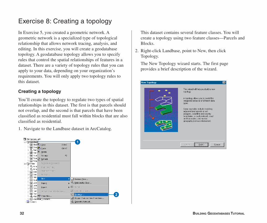
1. Navigate to the Landbase dataset in ArcCatalog.
Exercise 8: Creating a topology
This dataset contains several feature classes. You willcreate a topology using two feature classes—Parcels andBlocks.
2. Right-click Landbase, point to New, then clickTopology.
The New Topology wizard starts. The first pageprovides a brief description of the wizard.
1
2
Ch04.pmd 5/11/2006, 3:51 PM32
33
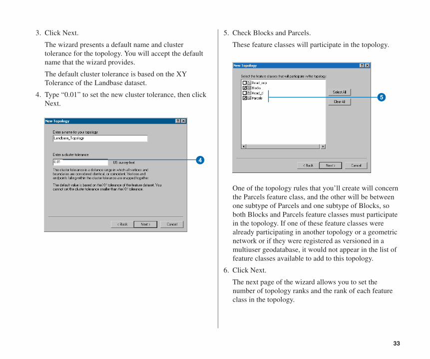
3. Click Next.
The wizard presents a default name and clustertolerance for the topology. You will accept the defaultname that the wizard provides.
The default cluster tolerance is based on the XYTolerance of the Landbase dataset.
4. Type “0.01” to set the new cluster tolerance, then clickNext.
5. Check Blocks and Parcels.
These feature classes will participate in the topology.
One of the topology rules that you’ll create will concernthe Parcels feature class, and the other will be betweenone subtype of Parcels and one subtype of Blocks, soboth Blocks and Parcels feature classes must participatein the topology. If one of these feature classes werealready participating in another topology or a geometricnetwork or if they were registered as versioned in amultiuser geodatabase, it would not appear in the list offeature classes available to add to this topology.
6. Click Next.
The next page of the wizard allows you to set thenumber of topology ranks and the rank of each featureclass in the topology.
5
4
Ch04.pmd 5/11/2006, 3:51 PM33
34 BUILDING GEODATABASES TUTORIAL
Ranks allow you to ensure that more accurately collectedfeatures are not snapped to the position of less accuratelycollected ones when the topology is validated. Forexample, if you were including a feature class that wascollected using a survey grade global positioning system(GPS) unit and a feature class digitized from a 1:1,000,000-scale source map in the same topology, you might assignthe GPS feature class a rank of 1 and the 1:1,000,000-scalesource feature class a rank of 5. If you were to validate thetopology, parts of features that fell within the clustertolerance would snap together, with the less accurate onesmoving to the location of the more accurate ones. The GPSfeatures would not be moved to the position of the1:1,000,000-scale features.
You can assign up to 50 different ranks, with 1 being thehighest rank. In this topology, you will assume that all thefeature classes are based on equally accurate data, so youwill not assign more than one rank. Parcels and Blockshave equivalent levels of accuracy, since the Blocks featureclass was derived from the parcel features.
7
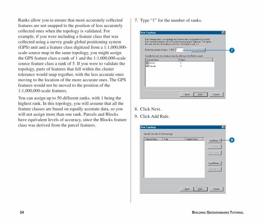
7. Type “1” for the number of ranks.
8. Click Next.
9. Click Add Rule.
9
Ch04.pmd 5/11/2006, 3:51 PM34
35
Topology rules allow you to define the permissiblespatial relationships of features within and betweenfeature classes that participate in the topology.
Landownership parcels are usually not allowed tooverlap each other. You will add a rule to prevent yourparcel features from overlapping each other.
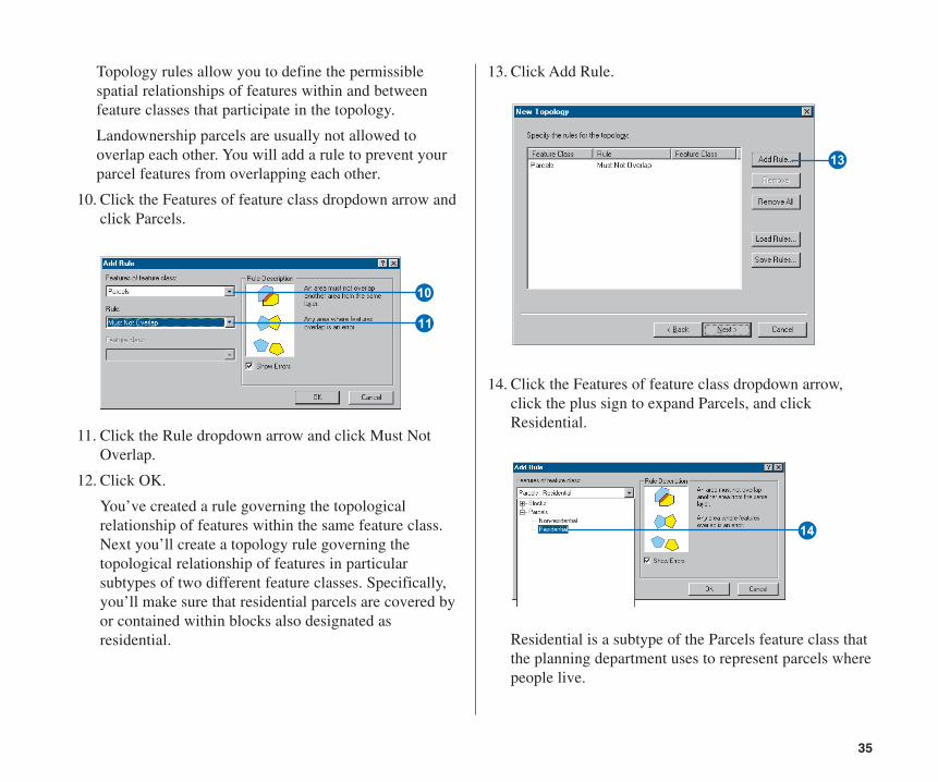
10. Click the Features of feature class dropdown arrow andclick Parcels.
11. Click the Rule dropdown arrow and click Must NotOverlap.
12. Click OK.
You’ve created a rule governing the topologicalrelationship of features within the same feature class.Next you’ll create a topology rule governing thetopological relationship of features in particularsubtypes of two different feature classes. Specifically,you’ll make sure that residential parcels are covered byor contained within blocks also designated asresidential.
R
13. Click Add Rule.
14. Click the Features of feature class dropdown arrow,click the plus sign to expand Parcels, and clickResidential.
Residential is a subtype of the Parcels feature class thatthe planning department uses to represent parcels wherepeople live.
T
W
Q
Ch04.pmd 5/11/2006, 3:51 PM35
36 BUILDING GEODATABASES TUTORIAL
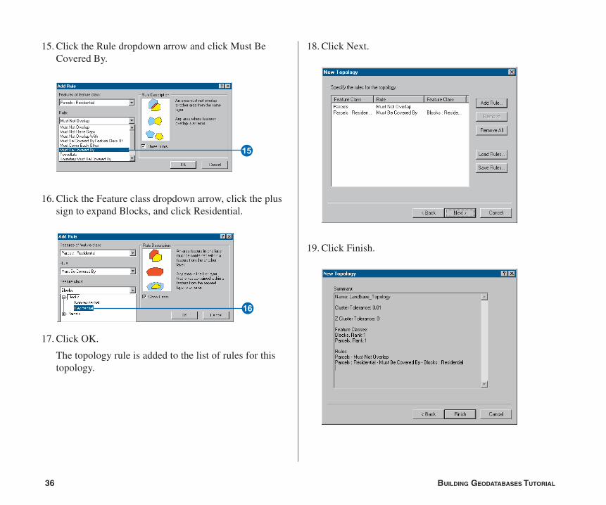
15. Click the Rule dropdown arrow and click Must BeCovered By.
16. Click the Feature class dropdown arrow, click the plussign to expand Blocks, and click Residential.
17. Click OK.
The topology rule is added to the list of rules for thistopology.
Y
U
18. Click Next.
19. Click Finish.
Ch04.pmd 5/11/2006, 3:51 PM36

37
After the topology is created, you have the opportunityto validate it. You do not need to validate the topologyimmediately after creating it. Depending on your dataand your work flow, it may make sense to assigndifferent areas to data editors to validate and edit withinArcMap.
20. Click No.
The topology appears in the Landbase dataset.
Topology
Ch04.pmd 5/11/2006, 3:51 PM37
38 BUILDING GEODATABASES TUTORIAL
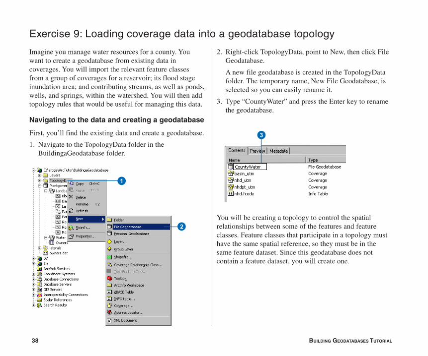
Imagine you manage water resources for a county. Youwant to create a geodatabase from existing data incoverages. You will import the relevant feature classesfrom a group of coverages for a reservoir; its flood stageinundation area; and contributing streams, as well as ponds,wells, and springs, within the watershed. You will then addtopology rules that would be useful for managing this data.
Navigating to the data and creating a geodatabase
First, you’ll find the existing data and create a geodatabase.
1. Navigate to the TopologyData folder in theBuildingaGeodatabase folder.
Exercise 9: Loading coverage data into a geodatabase topology
1
2
2. Right-click TopologyData, point to New, then click FileGeodatabase.
A new file geodatabase is created in the TopologyDatafolder. The temporary name, New File Geodatabase, isselected so you can easily rename it.
3. Type “CountyWater” and press the Enter key to renamethe geodatabase.
You will be creating a topology to control the spatialrelationships between some of the features and featureclasses. Feature classes that participate in a topology musthave the same spatial reference, so they must be in thesame feature dataset. Since this geodatabase does notcontain a feature dataset, you will create one.
3
Ch04.pmd 5/11/2006, 3:51 PM38
39
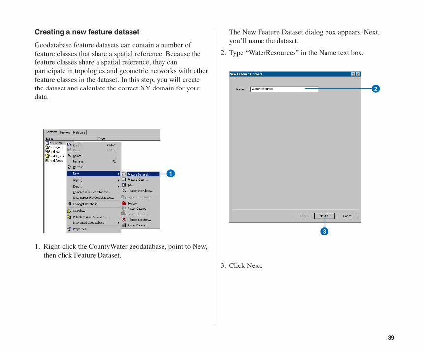
Creating a new feature dataset
Geodatabase feature datasets can contain a number offeature classes that share a spatial reference. Because thefeature classes share a spatial reference, they canparticipate in topologies and geometric networks with otherfeature classes in the dataset. In this step, you will createthe dataset and calculate the correct XY domain for yourdata.
1. Right-click the CountyWater geodatabase, point to New,then click Feature Dataset.
1
The New Feature Dataset dialog box appears. Next,you’ll name the dataset.
2. Type “WaterResources” in the Name text box.
3. Click Next.
2
3
Ch04.pmd 5/11/2006, 3:51 PM39
40 BUILDING GEODATABASES TUTORIAL
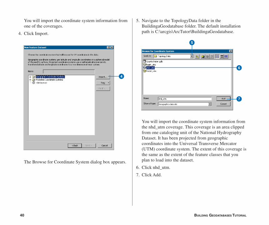
You will import the coordinate system information fromone of the coverages.
4. Click Import.
The Browse for Coordinate System dialog box appears.
4
5
6
7
5. Navigate to the TopologyData folder in theBuildingaGeodatabase folder. The default installationpath is C:\arcgis\ArcTutor\BuildingaGeodatabase.
You will import the coordinate system information fromthe nhd_utm coverage. This coverage is an area clippedfrom one cataloging unit of the National HydrographyDataset. It has been projected from geographiccoordinates into the Universal Transverse Mercator(UTM) coordinate system. The extent of this coverage isthe same as the extent of the feature classes that youplan to load into the dataset.
6. Click nhd_utm.
7. Click Add.
Ch04.pmd 5/11/2006, 3:51 PM40
41
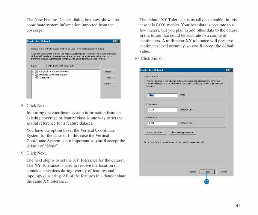
The New Feature Dataset dialog box now shows thecoordinate system information imported from thecoverage.
8. Click Next.
Importing the coordinate system information from anexisting coverage or feature class is one way to set thespatial reference for a feature dataset.
You have the option to set the Vertical CoordinateSystem for the dataset. In this case the VerticalCoordinate System is not important so you’ll accept thedefault of “None”.
9. Click Next.
The next step is to set the XY Tolerance for the dataset.The XY Tolerance is used to resolve the location ofcoincident vertices during overlay of features andtopology clustering. All of the features in a dataset sharethe same XY tolerance.
The default XY Tolerance is usually acceptable. In thiscase it is 0.001 meters. Your best data is accurate to afew meters, but you plan to add other data to the datasetin the future that could be accurate to a couple ofcentimeters. A millimeter XY tolerance will preservecentimeter level accuracy, so you’ll accept the defaultvalue.
10. Click Finish.
Q
Ch04.pmd 5/11/2006, 3:51 PM41
42 BUILDING GEODATABASES TUTORIAL
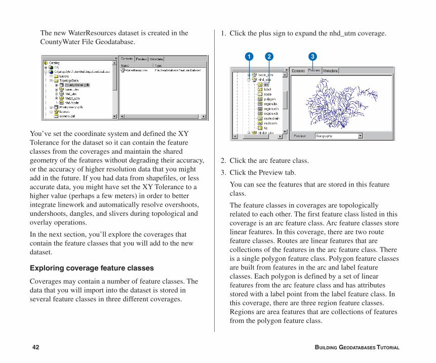
The new WaterResources dataset is created in theCountyWater File Geodatabase.
You’ve set the coordinate system and defined the XYTolerance for the dataset so it can contain the featureclasses from the coverages and maintain the sharedgeometry of the features without degrading their accuracy,or the accuracy of higher resolution data that you mightadd in the future. If you had data from shapefiles, or lessaccurate data, you might have set the XY Tolerance to ahigher value (perhaps a few meters) in order to betterintegrate linework and automatically resolve overshoots,undershoots, dangles, and slivers during topological andoverlay operations.
In the next section, you’ll explore the coverages thatcontain the feature classes that you will add to the newdataset.
Exploring coverage feature classes
Coverages may contain a number of feature classes. Thedata that you will import into the dataset is stored inseveral feature classes in three different coverages.
1. Click the plus sign to expand the nhd_utm coverage.
2. Click the arc feature class.
3. Click the Preview tab.
You can see the features that are stored in this featureclass.
The feature classes in coverages are topologicallyrelated to each other. The first feature class listed in thiscoverage is an arc feature class. Arc feature classes storelinear features. In this coverage, there are two routefeature classes. Routes are linear features that arecollections of the features in the arc feature class. Thereis a single polygon feature class. Polygon feature classesare built from features in the arc and label featureclasses. Each polygon is defined by a set of linearfeatures from the arc feature class and has attributesstored with a label point from the label feature class. Inthis coverage, there are three region feature classes.Regions are area features that are collections of featuresfrom the polygon feature class.
1 2 3
Ch04.pmd 5/11/2006, 3:51 PM42
43
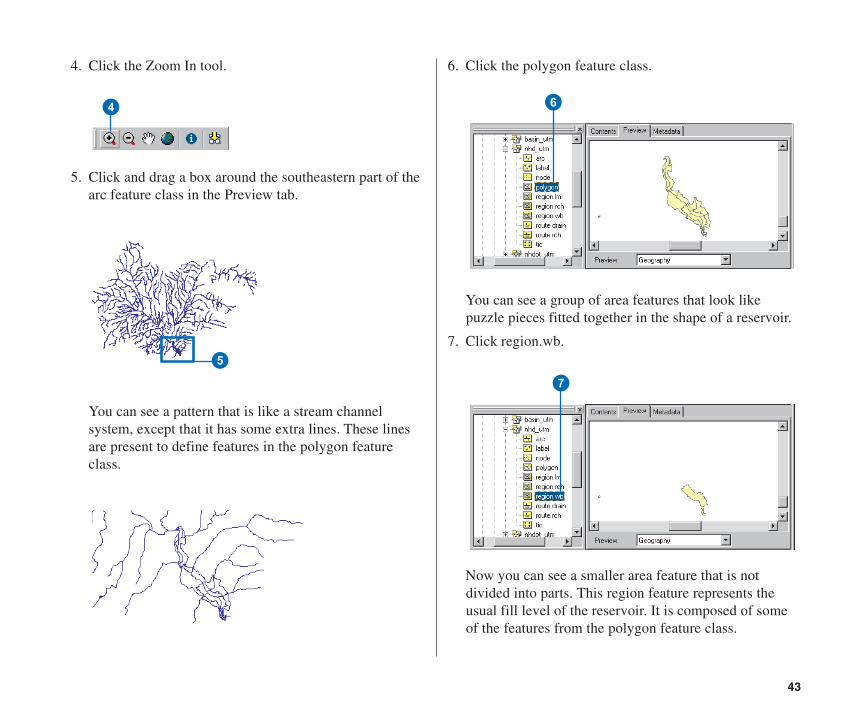
4. Click the Zoom In tool.
5. Click and drag a box around the southeastern part of thearc feature class in the Preview tab.
You can see a pattern that is like a stream channelsystem, except that it has some extra lines. These linesare present to define features in the polygon featureclass.
6. Click the polygon feature class.
You can see a group of area features that look likepuzzle pieces fitted together in the shape of a reservoir.
7. Click region.wb.
Now you can see a smaller area feature that is notdivided into parts. This region feature represents theusual fill level of the reservoir. It is composed of someof the features from the polygon feature class.
4
5
7
6
Ch04.pmd 5/11/2006, 3:51 PM43
44 BUILDING GEODATABASES TUTORIAL
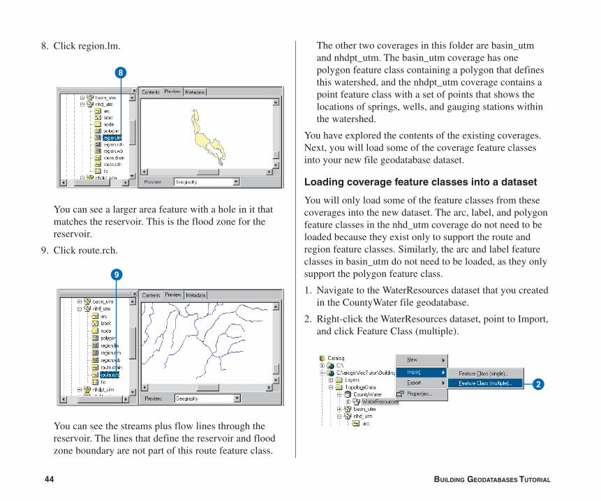
8. Click region.lm.
You can see a larger area feature with a hole in it thatmatches the reservoir. This is the flood zone for thereservoir.
9. Click route.rch.
You can see the streams plus flow lines through thereservoir. The lines that define the reservoir and floodzone boundary are not part of this route feature class.
The other two coverages in this folder are basin_utmand nhdpt_utm. The basin_utm coverage has onepolygon feature class containing a polygon that definesthis watershed, and the nhdpt_utm coverage contains apoint feature class with a set of points that shows thelocations of springs, wells, and gauging stations withinthe watershed.
You have explored the contents of the existing coverages.Next, you will load some of the coverage feature classesinto your new file geodatabase dataset.
Loading coverage feature classes into a dataset
You will only load some of the feature classes from thesecoverages into the new dataset. The arc, label, and polygonfeature classes in the nhd_utm coverage do not need to beloaded because they exist only to support the route andregion feature classes. Similarly, the arc and label featureclasses in basin_utm do not need to be loaded, as they onlysupport the polygon feature class.
1. Navigate to the WaterResources dataset that you createdin the CountyWater file geodatabase.
2. Right-click the WaterResources dataset, point to Import,and click Feature Class (multiple).
8
9
2
Ch04.pmd 5/11/2006, 3:51 PM44
45
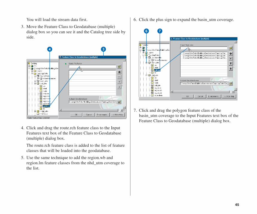
You will load the stream data first.
3. Move the Feature Class to Geodatabase (multiple)dialog box so you can see it and the Catalog tree side byside.
4. Click and drag the route.rch feature class to the InputFeatures text box of the Feature Class to Geodatabase(multiple) dialog box.
The route.rch feature class is added to the list of featureclasses that will be loaded into the geodatabase.
5. Use the same technique to add the region.wb andregion.lm feature classes from the nhd_utm coverage tothe list.
6. Click the plus sign to expand the basin_utm coverage.
7. Click and drag the polygon feature class of thebasin_utm coverage to the Input Features text box of theFeature Class to Geodatabase (multiple) dialog box.
34
76
Ch04.pmd 5/11/2006, 3:51 PM45
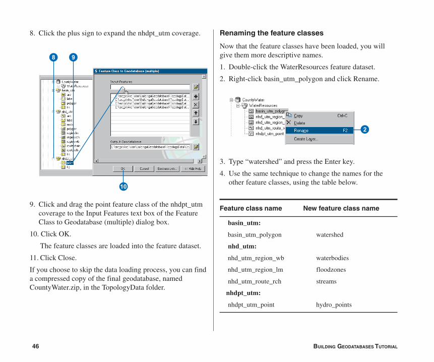
46 BUILDING GEODATABASES TUTORIAL
Renaming the feature classes
Now that the feature classes have been loaded, you willgive them more descriptive names.
1. Double-click the WaterResources feature dataset.
2. Right-click basin_utm_polygon and click Rename.
3. Type “watershed” and press the Enter key.
4. Use the same technique to change the names for theother feature classes, using the table below.
8. Click the plus sign to expand the nhdpt_utm coverage.
9. Click and drag the point feature class of the nhdpt_utmcoverage to the Input Features text box of the FeatureClass to Geodatabase (multiple) dialog box.
10. Click OK.
The feature classes are loaded into the feature dataset.
11. Click Close.
If you choose to skip the data loading process, you can finda compressed copy of the final geodatabase, namedCountyWater.zip, in the TopologyData folder.
98
Q
2
Feature class name New feature class name
basin_utm:
basin_utm_polygon watershed
nhd_utm:
nhd_utm_region_wb waterbodies
nhd_utm_region_lm floodzones
nhd_utm_route_rch streams
nhdpt_utm:
nhdpt_utm_point hydro_points
Ch04.pmd 5/11/2006, 3:51 PM46

47
Creating a topology
Now that the feature classes have been renamed, you willcreate a topology to regulate certain spatial relationshipsbetween and within these feature classes.
1. Right-click the WaterResources feature dataset, point toNew, and click Topology.
2. Click Next.
You could use this dialog box to rename the topology orincrease the cluster tolerance. The default clustertolerance is the XY Tolerance of the dataset. Parts offeatures within 0.001 meters of each other will besnapped together when the topology is validated. Thecluster tolerance cannot be made smaller than the XYTolerance, although it can be made larger.
Increasing the cluster tolerance to 0.5, for example,would cause vertices of features within 0.5 meters ofeach other to be snapped together in topology clustering.For this exercise, you will accept the default name andcluster tolerance.
3. Click Next.1
2
3
Ch04.pmd 5/12/2006, 11:28 AM47
48 BUILDING GEODATABASES TUTORIAL
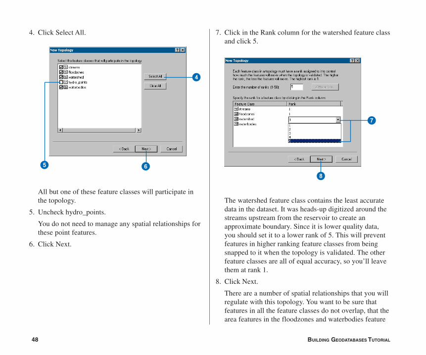
4. Click Select All.
All but one of these feature classes will participate inthe topology.
5. Uncheck hydro_points.
You do not need to manage any spatial relationships forthese point features.
6. Click Next.
7. Click in the Rank column for the watershed feature classand click 5.
The watershed feature class contains the least accuratedata in the dataset. It was heads-up digitized around thestreams upstream from the reservoir to create anapproximate boundary. Since it is lower quality data,you should set it to a lower rank of 5. This will preventfeatures in higher ranking feature classes from beingsnapped to it when the topology is validated. The otherfeature classes are all of equal accuracy, so you’ll leavethem at rank 1.
8. Click Next.
There are a number of spatial relationships that you willregulate with this topology. You want to be sure thatfeatures in all the feature classes do not overlap, that thearea features in the floodzones and waterbodies feature
6
4
5
7
8
Ch04.pmd 5/11/2006, 3:51 PM48
49
classes do not overlap each other, and that the streamfeatures do not have pseudonodes.
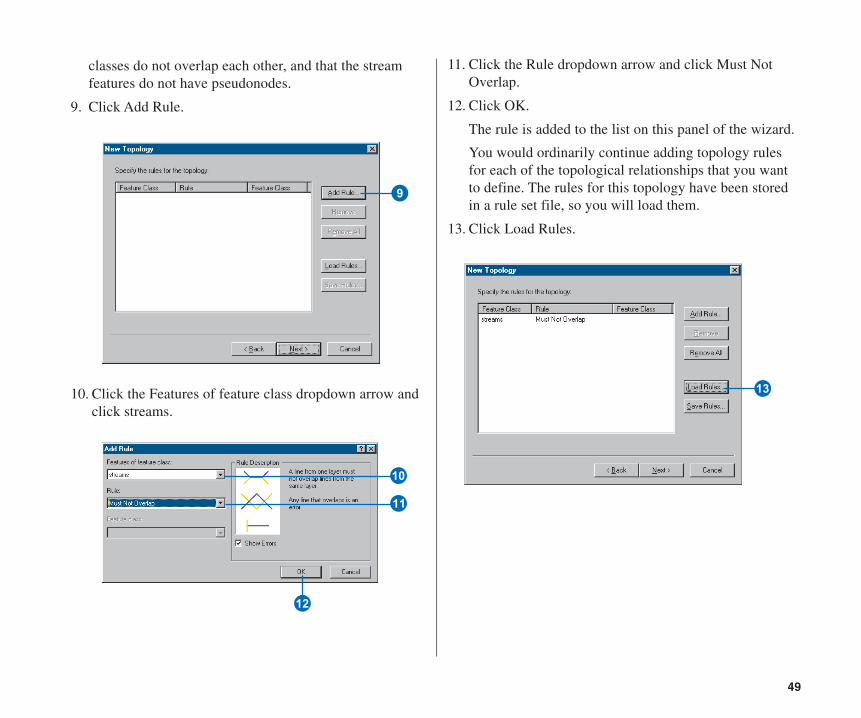
9. Click Add Rule.
10. Click the Features of feature class dropdown arrow andclick streams.
11. Click the Rule dropdown arrow and click Must NotOverlap.
12. Click OK.
The rule is added to the list on this panel of the wizard.
You would ordinarily continue adding topology rulesfor each of the topological relationships that you wantto define. The rules for this topology have been storedin a rule set file, so you will load them.
13. Click Load Rules.
9
Q
W
E
R
Ch04.pmd 5/11/2006, 3:51 PM49
50 BUILDING GEODATABASES TUTORIAL
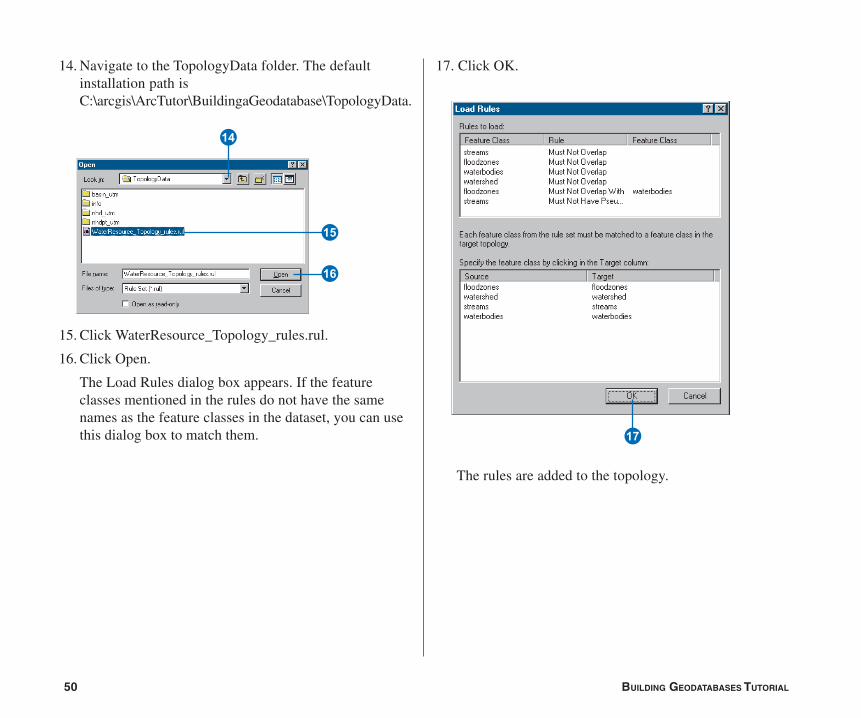
14. Navigate to the TopologyData folder. The defaultinstallation path isC:\arcgis\ArcTutor\BuildingaGeodatabase\TopologyData.
15. Click WaterResource_Topology_rules.rul.
16. Click Open.
The Load Rules dialog box appears. If the featureclasses mentioned in the rules do not have the samenames as the feature classes in the dataset, you can usethis dialog box to match them.
T
Y
U
17. Click OK.
The rules are added to the topology.
I
Ch04.pmd 5/11/2006, 3:51 PM50
51
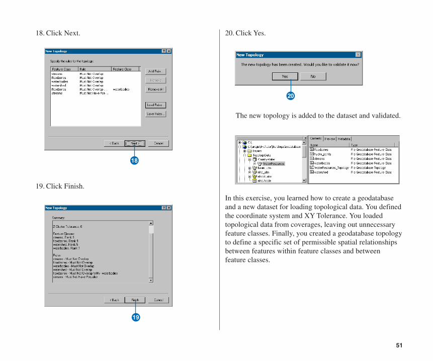
18. Click Next.
19. Click Finish.
O
P
20. Click Yes.
The new topology is added to the dataset and validated.
In this exercise, you learned how to create a geodatabaseand a new dataset for loading topological data. You definedthe coordinate system and XY Tolerance. You loadedtopological data from coverages, leaving out unnecessaryfeature classes. Finally, you created a geodatabase topologyto define a specific set of permissible spatial relationshipsbetween features within feature classes and betweenfeature classes.
A
Ch04.pmd 5/11/2006, 3:51 PM51
52 BUILDING GEODATABASES TUTORIAL
In the first exercise in this tutorial, you learned how tobegin organizing data for a geodatabase in ArcCatalog.
In Exercise 2, you learned how to import tables and featureclasses into a geodatabase.
In Exercise 3, you learned how to create subtypes andattribute domains in a geodatabase.
In Exercise 4, you learned how to create relationshipsbetween objects in a geodatabase.
In Exercise 5, you learned how to build a geometricnetwork in a geodatabase.
In Exercise 6, you learned how to create feature-linkedannotation in a geodatabase.
In Exercise 7, you learned how to create layers pointing tofeature classes in a geodatabase.
In Exercise 8, you learned how to create a geodatabasetopology.
In Exercise 9, you learned how to create a new dataset inwhich to load topological data and how to create a newtopology.
To learn more about these topics see the ArcGIS DesktopHelp system.
Ch04.pmd 5/11/2006, 3:51 PM52