Embed Size (px)
Citation preview
Building a Scalable andSecure Multi-VPC AWSNetwork Infrastructure
AWS Whitepaper
Building a Scalable and Secure Multi-VPCAWS Network Infrastructure AWS Whitepaper
Building a Scalable and Secure Multi-VPC AWS Network Infrastructure:AWS WhitepaperCopyright © 2020 Amazon Web Services, Inc. and/or its affiliates. All rights reserved.
Amazon's trademarks and trade dress may not be used in connection with any product or service that is notAmazon's, in any manner that is likely to cause confusion among customers, or in any manner that disparages ordiscredits Amazon. All other trademarks not owned by Amazon are the property of their respective owners, who mayor may not be affiliated with, connected to, or sponsored by Amazon.
Building a Scalable and Secure Multi-VPCAWS Network Infrastructure AWS Whitepaper
Table of ContentsAbstract ... . . . . . . . . . . . . . . . . . . . . . . . . . . . . . . . . . . . . . . . . . . . . . . . . . . . . . . . . . . . . . . . . . . . . . . . . . . . . . . . . . . . . . . . . . . . . . . . . . . . . . . . . . . . . . . . . . . . . . . . . . . . . . . . . . . . . . . . . . 1
Abstract ... . . . . . . . . . . . . . . . . . . . . . . . . . . . . . . . . . . . . . . . . . . . . . . . . . . . . . . . . . . . . . . . . . . . . . . . . . . . . . . . . . . . . . . . . . . . . . . . . . . . . . . . . . . . . . . . . . . . . . . . . . . . . . . . . . 1Introduction .... . . . . . . . . . . . . . . . . . . . . . . . . . . . . . . . . . . . . . . . . . . . . . . . . . . . . . . . . . . . . . . . . . . . . . . . . . . . . . . . . . . . . . . . . . . . . . . . . . . . . . . . . . . . . . . . . . . . . . . . . . . . . . . . . . . 2VPC to VPC connectivity ... . . . . . . . . . . . . . . . . . . . . . . . . . . . . . . . . . . . . . . . . . . . . . . . . . . . . . . . . . . . . . . . . . . . . . . . . . . . . . . . . . . . . . . . . . . . . . . . . . . . . . . . . . . . . . . . . . . 4
VPC peering .... . . . . . . . . . . . . . . . . . . . . . . . . . . . . . . . . . . . . . . . . . . . . . . . . . . . . . . . . . . . . . . . . . . . . . . . . . . . . . . . . . . . . . . . . . . . . . . . . . . . . . . . . . . . . . . . . . . . . . . . . . . 4Transit VPC Solution .... . . . . . . . . . . . . . . . . . . . . . . . . . . . . . . . . . . . . . . . . . . . . . . . . . . . . . . . . . . . . . . . . . . . . . . . . . . . . . . . . . . . . . . . . . . . . . . . . . . . . . . . . . . . . . . . 5Transit Gateway ... . . . . . . . . . . . . . . . . . . . . . . . . . . . . . . . . . . . . . . . . . . . . . . . . . . . . . . . . . . . . . . . . . . . . . . . . . . . . . . . . . . . . . . . . . . . . . . . . . . . . . . . . . . . . . . . . . . . . . 6
Transit Gateway vs Transit VPC .... . . . . . . . . . . . . . . . . . . . . . . . . . . . . . . . . . . . . . . . . . . . . . . . . . . . . . . . . . . . . . . . . . . . . . . . . . . . . . . . . . . . . . . . . 6Transit Gateway vs VPC peering .... . . . . . . . . . . . . . . . . . . . . . . . . . . . . . . . . . . . . . . . . . . . . . . . . . . . . . . . . . . . . . . . . . . . . . . . . . . . . . . . . . . . . . . . 7
AWS PrivateLink .... . . . . . . . . . . . . . . . . . . . . . . . . . . . . . . . . . . . . . . . . . . . . . . . . . . . . . . . . . . . . . . . . . . . . . . . . . . . . . . . . . . . . . . . . . . . . . . . . . . . . . . . . . . . . . . . . . . . . . 7Amazon VPC Sharing .... . . . . . . . . . . . . . . . . . . . . . . . . . . . . . . . . . . . . . . . . . . . . . . . . . . . . . . . . . . . . . . . . . . . . . . . . . . . . . . . . . . . . . . . . . . . . . . . . . . . . . . . . . . . . . . 8
Hybrid Connectivity ... . . . . . . . . . . . . . . . . . . . . . . . . . . . . . . . . . . . . . . . . . . . . . . . . . . . . . . . . . . . . . . . . . . . . . . . . . . . . . . . . . . . . . . . . . . . . . . . . . . . . . . . . . . . . . . . . . . . . . . . 10VPN .... . . . . . . . . . . . . . . . . . . . . . . . . . . . . . . . . . . . . . . . . . . . . . . . . . . . . . . . . . . . . . . . . . . . . . . . . . . . . . . . . . . . . . . . . . . . . . . . . . . . . . . . . . . . . . . . . . . . . . . . . . . . . . . . . . . . 10Direct Connect ... . . . . . . . . . . . . . . . . . . . . . . . . . . . . . . . . . . . . . . . . . . . . . . . . . . . . . . . . . . . . . . . . . . . . . . . . . . . . . . . . . . . . . . . . . . . . . . . . . . . . . . . . . . . . . . . . . . . . . 11
Centralized egress to internet .... . . . . . . . . . . . . . . . . . . . . . . . . . . . . . . . . . . . . . . . . . . . . . . . . . . . . . . . . . . . . . . . . . . . . . . . . . . . . . . . . . . . . . . . . . . . . . . . . . . . . . . . . 14Centralized network security for VPC-to-VPC and on-premises to VPC traffic .... . . . . . . . . . . . . . . . . . . . . . . . . . . . . . . . . . . . . . . . . 18DNS .... . . . . . . . . . . . . . . . . . . . . . . . . . . . . . . . . . . . . . . . . . . . . . . . . . . . . . . . . . . . . . . . . . . . . . . . . . . . . . . . . . . . . . . . . . . . . . . . . . . . . . . . . . . . . . . . . . . . . . . . . . . . . . . . . . . . . . . . . . . . . 21
Hybrid DNS .... . . . . . . . . . . . . . . . . . . . . . . . . . . . . . . . . . . . . . . . . . . . . . . . . . . . . . . . . . . . . . . . . . . . . . . . . . . . . . . . . . . . . . . . . . . . . . . . . . . . . . . . . . . . . . . . . . . . . . . . . . 21Centralized access to VPC private endpoints ... . . . . . . . . . . . . . . . . . . . . . . . . . . . . . . . . . . . . . . . . . . . . . . . . . . . . . . . . . . . . . . . . . . . . . . . . . . . . . . . . . . . . . 24
Interface VPC endpoints ... . . . . . . . . . . . . . . . . . . . . . . . . . . . . . . . . . . . . . . . . . . . . . . . . . . . . . . . . . . . . . . . . . . . . . . . . . . . . . . . . . . . . . . . . . . . . . . . . . . . . . . . . . 24Conclusion .... . . . . . . . . . . . . . . . . . . . . . . . . . . . . . . . . . . . . . . . . . . . . . . . . . . . . . . . . . . . . . . . . . . . . . . . . . . . . . . . . . . . . . . . . . . . . . . . . . . . . . . . . . . . . . . . . . . . . . . . . . . . . . . . . . . . 27Contributors ... . . . . . . . . . . . . . . . . . . . . . . . . . . . . . . . . . . . . . . . . . . . . . . . . . . . . . . . . . . . . . . . . . . . . . . . . . . . . . . . . . . . . . . . . . . . . . . . . . . . . . . . . . . . . . . . . . . . . . . . . . . . . . . . . . 28Document History .... . . . . . . . . . . . . . . . . . . . . . . . . . . . . . . . . . . . . . . . . . . . . . . . . . . . . . . . . . . . . . . . . . . . . . . . . . . . . . . . . . . . . . . . . . . . . . . . . . . . . . . . . . . . . . . . . . . . . . . . . 29Notices .... . . . . . . . . . . . . . . . . . . . . . . . . . . . . . . . . . . . . . . . . . . . . . . . . . . . . . . . . . . . . . . . . . . . . . . . . . . . . . . . . . . . . . . . . . . . . . . . . . . . . . . . . . . . . . . . . . . . . . . . . . . . . . . . . . . . . . . . . 30
iii
Building a Scalable and Secure Multi-VPCAWS Network Infrastructure AWS Whitepaper
Abstract
Building a Scalable and Secure Multi-VPC AWS Network Infrastructure
Publication date: June 2020 (Document History (p. 29))
AbstractAWS customers often rely on hundreds of accounts and VPCs to segment their workloads andexpand their footprint. This level of scale often creates challenges around resource sharing, inter-VPCconnectivity, and on-premises to VPC connectivity.
This whitepaper describes best practices for creating scalable and secure network architectures in a largenetwork using AWS services like Amazon VPC, AWS Transit Gateway, AWS PrivateLink, and AWS DirectConnect Gateway. It demonstrates solutions for managing growing infrastructure — ensuring scalability,high availability, and security while keeping overhead costs low.
1
Building a Scalable and Secure Multi-VPCAWS Network Infrastructure AWS Whitepaper
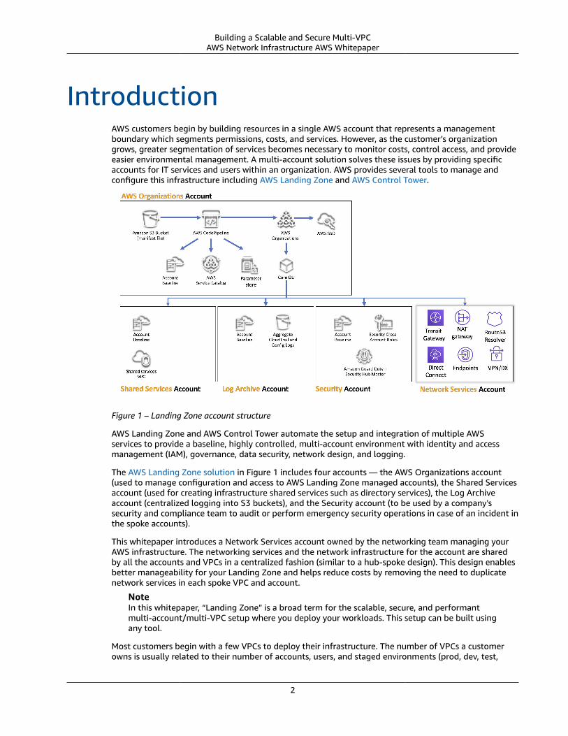
IntroductionAWS customers begin by building resources in a single AWS account that represents a managementboundary which segments permissions, costs, and services. However, as the customer’s organizationgrows, greater segmentation of services becomes necessary to monitor costs, control access, and provideeasier environmental management. A multi-account solution solves these issues by providing specificaccounts for IT services and users within an organization. AWS provides several tools to manage andconfigure this infrastructure including AWS Landing Zone and AWS Control Tower.
Figure 1 – Landing Zone account structure
AWS Landing Zone and AWS Control Tower automate the setup and integration of multiple AWSservices to provide a baseline, highly controlled, multi-account environment with identity and accessmanagement (IAM), governance, data security, network design, and logging.
The AWS Landing Zone solution in Figure 1 includes four accounts — the AWS Organizations account(used to manage configuration and access to AWS Landing Zone managed accounts), the Shared Servicesaccount (used for creating infrastructure shared services such as directory services), the Log Archiveaccount (centralized logging into S3 buckets), and the Security account (to be used by a company'ssecurity and compliance team to audit or perform emergency security operations in case of an incident inthe spoke accounts).
This whitepaper introduces a Network Services account owned by the networking team managing yourAWS infrastructure. The networking services and the network infrastructure for the account are sharedby all the accounts and VPCs in a centralized fashion (similar to a hub-spoke design). This design enablesbetter manageability for your Landing Zone and helps reduce costs by removing the need to duplicatenetwork services in each spoke VPC and account.
NoteIn this whitepaper, “Landing Zone” is a broad term for the scalable, secure, and performantmulti-account/multi-VPC setup where you deploy your workloads. This setup can be built usingany tool.
Most customers begin with a few VPCs to deploy their infrastructure. The number of VPCs a customerowns is usually related to their number of accounts, users, and staged environments (prod, dev, test,
2
Building a Scalable and Secure Multi-VPCAWS Network Infrastructure AWS Whitepaper
etc.). As cloud usage grows, the number of users, business units, applications, and Regions that acustomer interacts with multiply, leading to the creation of new VPCs.
As the number of VPCs grows, cross-VPC management becomes essential for the operation of thecustomer’s cloud network. This whitepaper covers best practices for three specific areas in cross-VPC andhybrid connectivity:
• Network connectivity – Interconnecting VPCs and on-premises networks at scale.• Network security – Building centralized egress points for accessing the internet and endpoints like
NAT Gateway, VPC endpoints, and AWS PrivateLink.• DNS management – Resolving DNS within the Landing Zone and hybrid DNS.
3
Building a Scalable and Secure Multi-VPCAWS Network Infrastructure AWS Whitepaper
VPC peering
VPC to VPC connectivityCustomers can use two different VPC flow patterns to set up multi-VPC environments: many-to-many,or hub-and-spoke. In the many-to-many approach, the traffic between each VPC is managed individuallybetween each VPC. In the hub-and-spoke model, all inter-VPC traffic flows through a central resource,which routes traffic based on established rules.
Topics• VPC peering (p. 4)• Transit VPC Solution (p. 5)• Transit Gateway (p. 6)• AWS PrivateLink (p. 7)• Amazon VPC Sharing (p. 8)
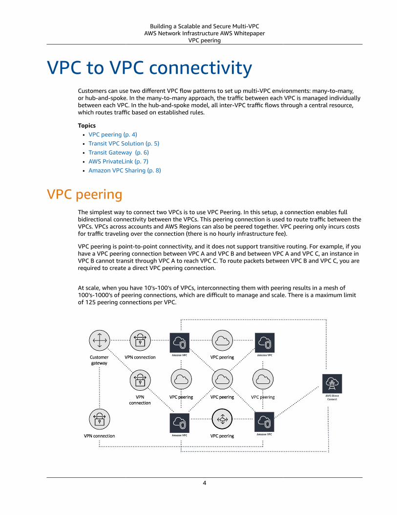
VPC peeringThe simplest way to connect two VPCs is to use VPC Peering. In this setup, a connection enables fullbidirectional connectivity between the VPCs. This peering connection is used to route traffic between theVPCs. VPCs across accounts and AWS Regions can also be peered together. VPC peering only incurs costsfor traffic traveling over the connection (there is no hourly infrastructure fee).
VPC peering is point-to-point connectivity, and it does not support transitive routing. For example, if youhave a VPC peering connection between VPC A and VPC B and between VPC A and VPC C, an instance inVPC B cannot transit through VPC A to reach VPC C. To route packets between VPC B and VPC C, you arerequired to create a direct VPC peering connection.
At scale, when you have 10’s-100’s of VPCs, interconnecting them with peering results in a mesh of100’s-1000’s of peering connections, which are difficult to manage and scale. There is a maximum limitof 125 peering connections per VPC.
4
Building a Scalable and Secure Multi-VPCAWS Network Infrastructure AWS Whitepaper
Transit VPC Solution
Figure 2 – Network setup using VPC Peering
If you are using VPC peering, on-premises connectivity (VPN and/or Direct Connect) must be made toeach VPC. Resources in a VPC cannot reach on-premises using the hybrid connectivity of a peered VPC(Figure 2).
VPC peering is best used when resources in one VPC must communicate with resources in another VPC,the environment of both VPCs is controlled and secured, and the number of VPCs to be connected isless than 10 (to allow for the individual management of each connection). VPC peering offers the lowestoverall cost when compared to other options for inter-VPC connectivity.
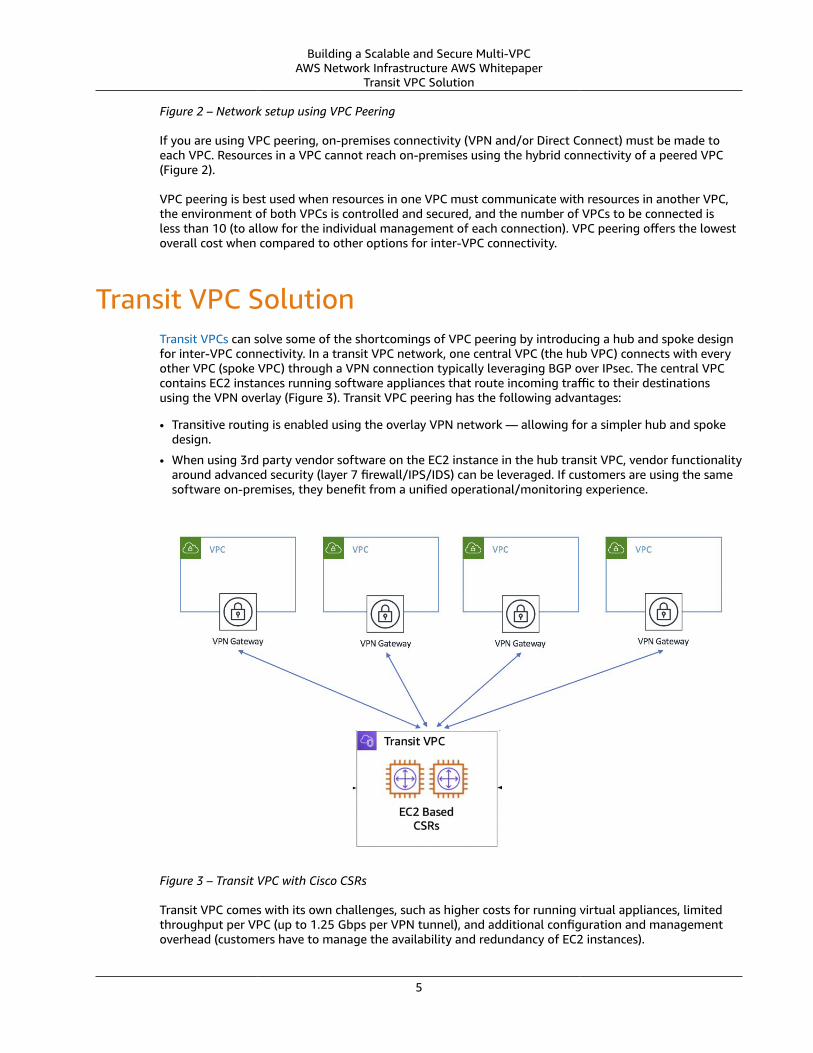
Transit VPC SolutionTransit VPCs can solve some of the shortcomings of VPC peering by introducing a hub and spoke designfor inter-VPC connectivity. In a transit VPC network, one central VPC (the hub VPC) connects with everyother VPC (spoke VPC) through a VPN connection typically leveraging BGP over IPsec. The central VPCcontains EC2 instances running software appliances that route incoming traffic to their destinationsusing the VPN overlay (Figure 3). Transit VPC peering has the following advantages:
• Transitive routing is enabled using the overlay VPN network — allowing for a simpler hub and spokedesign.
• When using 3rd party vendor software on the EC2 instance in the hub transit VPC, vendor functionalityaround advanced security (layer 7 firewall/IPS/IDS) can be leveraged. If customers are using the samesoftware on-premises, they benefit from a unified operational/monitoring experience.
Figure 3 – Transit VPC with Cisco CSRs
Transit VPC comes with its own challenges, such as higher costs for running virtual appliances, limitedthroughput per VPC (up to 1.25 Gbps per VPN tunnel), and additional configuration and managementoverhead (customers have to manage the availability and redundancy of EC2 instances).
5
Building a Scalable and Secure Multi-VPCAWS Network Infrastructure AWS Whitepaper
Transit Gateway
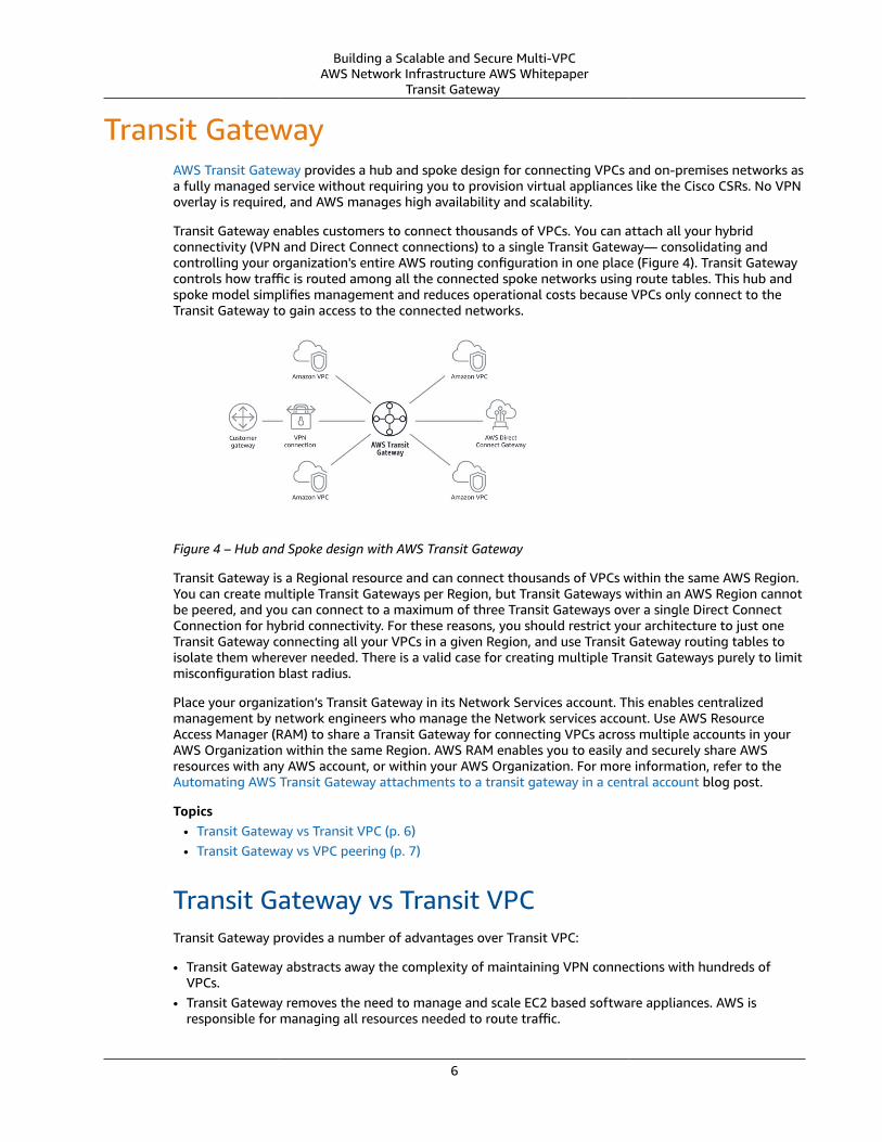
Transit Gateway AWS Transit Gateway provides a hub and spoke design for connecting VPCs and on-premises networks asa fully managed service without requiring you to provision virtual appliances like the Cisco CSRs. No VPNoverlay is required, and AWS manages high availability and scalability.
Transit Gateway enables customers to connect thousands of VPCs. You can attach all your hybridconnectivity (VPN and Direct Connect connections) to a single Transit Gateway— consolidating andcontrolling your organization's entire AWS routing configuration in one place (Figure 4). Transit Gatewaycontrols how traffic is routed among all the connected spoke networks using route tables. This hub andspoke model simplifies management and reduces operational costs because VPCs only connect to theTransit Gateway to gain access to the connected networks.
Figure 4 – Hub and Spoke design with AWS Transit Gateway
Transit Gateway is a Regional resource and can connect thousands of VPCs within the same AWS Region.You can create multiple Transit Gateways per Region, but Transit Gateways within an AWS Region cannotbe peered, and you can connect to a maximum of three Transit Gateways over a single Direct ConnectConnection for hybrid connectivity. For these reasons, you should restrict your architecture to just oneTransit Gateway connecting all your VPCs in a given Region, and use Transit Gateway routing tables toisolate them wherever needed. There is a valid case for creating multiple Transit Gateways purely to limitmisconfiguration blast radius.
Place your organization’s Transit Gateway in its Network Services account. This enables centralizedmanagement by network engineers who manage the Network services account. Use AWS ResourceAccess Manager (RAM) to share a Transit Gateway for connecting VPCs across multiple accounts in yourAWS Organization within the same Region. AWS RAM enables you to easily and securely share AWSresources with any AWS account, or within your AWS Organization. For more information, refer to theAutomating AWS Transit Gateway attachments to a transit gateway in a central account blog post.
Topics• Transit Gateway vs Transit VPC (p. 6)• Transit Gateway vs VPC peering (p. 7)
Transit Gateway vs Transit VPCTransit Gateway provides a number of advantages over Transit VPC:
• Transit Gateway abstracts away the complexity of maintaining VPN connections with hundreds ofVPCs.
• Transit Gateway removes the need to manage and scale EC2 based software appliances. AWS isresponsible for managing all resources needed to route traffic.
6
Building a Scalable and Secure Multi-VPCAWS Network Infrastructure AWS Whitepaper
Transit Gateway vs VPC peering
• Transit Gateway removes the need to manage high availability by providing a highly available andredundant Multi-AZ infrastructure.
• Transit Gateway improves bandwidth for inter-VPC communication to burst speeds of 50 Gbps per AZ.• Transit Gateway streamlines user costs to a simple per hour per/GB transferred model.• Transit Gateway decreases latency by removing EC2 proxies and the need for VPN encapsulation.
Transit Gateway vs VPC peeringTransit Gateway solves the complexity involved with creating and managing multiple VPC peeringconnections at scale. While this makes TGW a good default for most network architectures, VPC peeringis still a valid choice due to the following advantages it has over TGW:
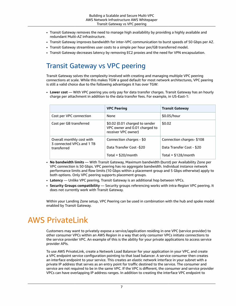
• Lower cost — With VPC peering you only pay for data transfer charges. Transit Gateway has an hourlycharge per attachment in addition to the data transfer fees. For example, in US-East-1:
VPC Peering Transit Gateway
Cost per VPC connection None $0.05/hour
Cost per GB transferred $0.02 (0.01 charged to senderVPC owner and 0.01 charged toreceiver VPC owner)
$0.02
Overall monthly cost with3 connected VPCs and 1 TBtransferred
Connection charges - $0
Data Transfer Cost -$20
Total = $20/month
Connection charges- $108
Data Transfer Cost - $20
Total = $128/month
• No bandwidth limits — With Transit Gateway, Maximum bandwidth (burst) per Availability Zone perVPC connection is 50 Gbps. VPC peering has no aggregate bandwidth. Individual instance networkperformance limits and flow limits (10 Gbps within a placement group and 5 Gbps otherwise) apply toboth options. Only VPC peering supports placement groups.
• Latency — Unlike VPC peering, Transit Gateway is an additional hop between VPCs.• Security Groups compatibility — Security groups referencing works with intra-Region VPC peering. It
does not currently work with Transit Gateway.
Within your Landing Zone setup, VPC Peering can be used in combination with the hub and spoke modelenabled by Transit Gateway.
AWS PrivateLinkCustomers may want to privately expose a service/application residing in one VPC (service provider) toother consumer VPCs within an AWS Region in a way that only consumer VPCs initiate connections tothe service provider VPC. An example of this is the ability for your private applications to access serviceprovider APIs.
To use AWS PrivateLink, create a Network Load Balancer for your application in your VPC, and createa VPC endpoint service configuration pointing to that load balancer. A service consumer then createsan interface endpoint to your service. This creates an elastic network interface in your subnet with aprivate IP address that serves as an entry point for traffic destined to the service. The consumer andservice are not required to be in the same VPC. If the VPC is different, the consumer and service providerVPCs can have overlapping IP address ranges. In addition to creating the interface VPC endpoint to
7
Building a Scalable and Secure Multi-VPCAWS Network Infrastructure AWS Whitepaper
Amazon VPC Sharing
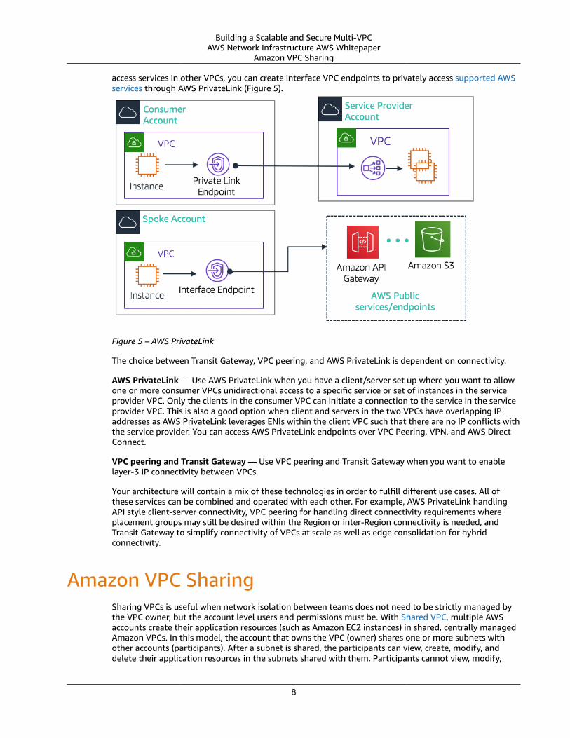
access services in other VPCs, you can create interface VPC endpoints to privately access supported AWSservices through AWS PrivateLink (Figure 5).
Figure 5 – AWS PrivateLink
The choice between Transit Gateway, VPC peering, and AWS PrivateLink is dependent on connectivity.
AWS PrivateLink — Use AWS PrivateLink when you have a client/server set up where you want to allowone or more consumer VPCs unidirectional access to a specific service or set of instances in the serviceprovider VPC. Only the clients in the consumer VPC can initiate a connection to the service in the serviceprovider VPC. This is also a good option when client and servers in the two VPCs have overlapping IPaddresses as AWS PrivateLink leverages ENIs within the client VPC such that there are no IP conflicts withthe service provider. You can access AWS PrivateLink endpoints over VPC Peering, VPN, and AWS DirectConnect.
VPC peering and Transit Gateway — Use VPC peering and Transit Gateway when you want to enablelayer-3 IP connectivity between VPCs.
Your architecture will contain a mix of these technologies in order to fulfill different use cases. All ofthese services can be combined and operated with each other. For example, AWS PrivateLink handlingAPI style client-server connectivity, VPC peering for handling direct connectivity requirements whereplacement groups may still be desired within the Region or inter-Region connectivity is needed, andTransit Gateway to simplify connectivity of VPCs at scale as well as edge consolidation for hybridconnectivity.
Amazon VPC SharingSharing VPCs is useful when network isolation between teams does not need to be strictly managed bythe VPC owner, but the account level users and permissions must be. With Shared VPC, multiple AWSaccounts create their application resources (such as Amazon EC2 instances) in shared, centrally managedAmazon VPCs. In this model, the account that owns the VPC (owner) shares one or more subnets withother accounts (participants). After a subnet is shared, the participants can view, create, modify, anddelete their application resources in the subnets shared with them. Participants cannot view, modify,
8
Building a Scalable and Secure Multi-VPCAWS Network Infrastructure AWS Whitepaper
Amazon VPC Sharing
or delete resources that belong to other participants or the VPC owner. Security between resources inshared VPCs is managed using security groups and subnet network ACLs.
VPC sharing benefits:
• Simplified design — no complexity around inter-VPC connectivity• Fewer managed VPCs• Segregation of duties between network teams and application owners• Better IPv4 address utilization• Lower costs — no data transfer charges between instances belonging to different accounts within the
same Availability Zone
Note: When you share a subnet with multiple accounts, your participants should have some level ofcooperation since they're sharing IP space and network resources. If necessary, you can choose to sharea different subnet for each participant account. One subnet per participant enables network ACL toprovide network isolation in addition to security groups.
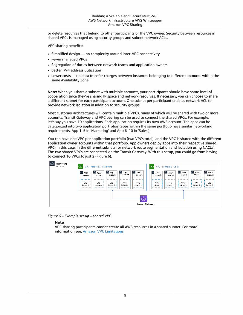
Most customer architectures will contain multiple VPCs, many of which will be shared with two or moreaccounts. Transit Gateway and VPC peering can be used to connect the shared VPCs. For example,let’s say you have 10 applications. Each application requires its own AWS account. The apps can becategorized into two application portfolios (apps within the same portfolio have similar networkingrequirements, App 1–5 in ‘Marketing’ and App 6–10 in ‘Sales’).
You can have one VPC per application portfolio (two VPCs total), and the VPC is shared with the differentapplication owner accounts within that portfolio. App owners deploy apps into their respective sharedVPC (in this case, in the different subnets for network route segmentation and isolation using NACLs).The two shared VPCs are connected via the Transit Gateway. With this setup, you could go from havingto connect 10 VPCs to just 2 (Figure 6).
Figure 6 – Example set up – shared VPC
NoteVPC sharing participants cannot create all AWS resources in a shared subnet. For moreinformation see, Amazon VPC Limitations.
9
Building a Scalable and Secure Multi-VPCAWS Network Infrastructure AWS Whitepaper
VPN
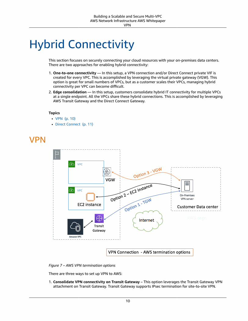
Hybrid ConnectivityThis section focuses on securely connecting your cloud resources with your on-premises data centers.There are two approaches for enabling hybrid connectivity:
1. One-to-one connectivity — In this setup, a VPN connection and/or Direct Connect private VIF iscreated for every VPC. This is accomplished by leveraging the virtual private gateway (VGW). Thisoption is great for small numbers of VPCs, but as a customer scales their VPCs, managing hybridconnectivity per VPC can become difficult.
2. Edge consolidation — In this setup, customers consolidate hybrid IT connectivity for multiple VPCsat a single endpoint. All the VPCs share these hybrid connections. This is accomplished by leveragingAWS Transit Gateway and the Direct Connect Gateway.
Topics• VPN (p. 10)• Direct Connect (p. 11)
VPN
Figure 7 – AWS VPN termination options
There are three ways to set up VPN to AWS:
1. Consolidate VPN connectivity on Transit Gateway – This option leverages the Transit Gateway VPNattachment on Transit Gateway. Transit Gateway supports IPsec termination for site-to-site VPN.
10
Building a Scalable and Secure Multi-VPCAWS Network Infrastructure AWS Whitepaper
Direct Connect
Customers can create VPN tunnels to the Transit Gateway, and can access the VPCs attached to it.Transit Gateway supports both Static and BGP-based Dynamic VPN connections. Transit Gateway alsosupports Equal-Cost Multi-Path (ECMP) on VPN attachments. Each VPN connection has a maximumof 1.25-Gbps throughput, and enabling ECMP allows you to aggregate throughput across VPNconnections. In this option, you pay for Transit Gateway pricing as well as AWS VPN pricing. Werecommended using this option for VPN connectivity. For more information, consult the AWS VPNOverview.
2. Terminate VPN on EC2 instance – This option is leveraged by customers in edge cases when theywant a particular vendor software feature set (like Cisco DMVPN or GRE), or they want operationalconsistency across various VPN deployments. You can leverage the transit VPC design for edgeconsolidation, but it is important to remember that all the key considerations from the VPC-to-VPCconnectivity section for transit VPC are applicable to hybrid VPN connectivity. You are responsiblefor managing high availability, and you pay for EC2 instance costs as well as any vendor softwarelicensing.
3. Terminate VPN on a virtual private gateway (VGW) – This option enables a one-to-one connectivitydesign where you create one VPN connection (consisting of a pair of redundant VPN tunnels) perVPC. This is great way to get started with VPN connectivity into AWS, but as you scale the numberof VPCs, edge consolidation design leveraging Transit Gateway will eventually be a better option.VPN throughput to a VPC is limited to 1.25 Gbps and ECMP load balancing is not supported. From apricing perspective, you only pay for AWS VPN pricing, there is no charge for running a VGW. For moreinformation see, AWS VPN Pricing and AWS VPN on virtual private gateway.
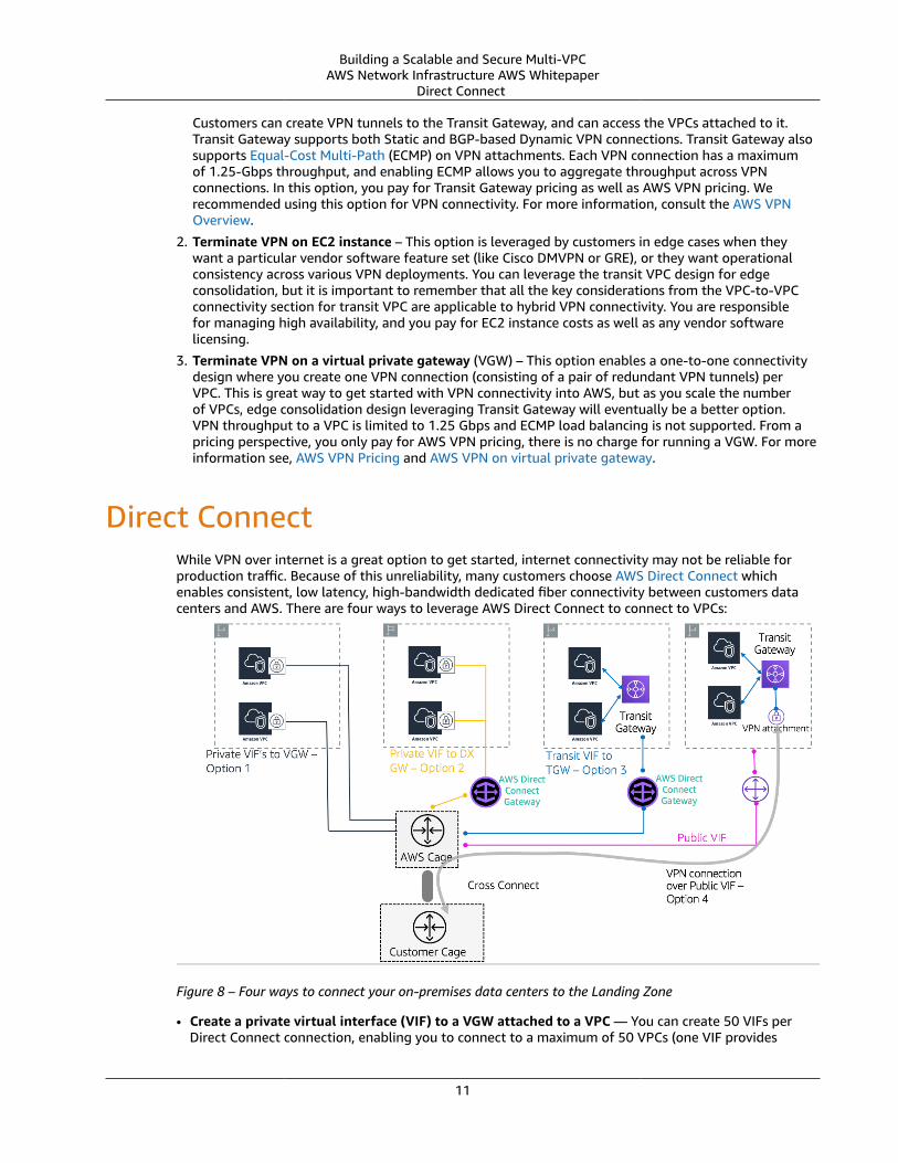
Direct Connect While VPN over internet is a great option to get started, internet connectivity may not be reliable forproduction traffic. Because of this unreliability, many customers choose AWS Direct Connect whichenables consistent, low latency, high-bandwidth dedicated fiber connectivity between customers datacenters and AWS. There are four ways to leverage AWS Direct Connect to connect to VPCs:
Figure 8 – Four ways to connect your on-premises data centers to the Landing Zone
• Create a private virtual interface (VIF) to a VGW attached to a VPC — You can create 50 VIFs perDirect Connect connection, enabling you to connect to a maximum of 50 VPCs (one VIF provides
11
Building a Scalable and Secure Multi-VPCAWS Network Infrastructure AWS Whitepaper
Direct Connect
connectivity to one VPC). There is one BGP peering per VPC. Connectivity in this setup is restricted tothe AWS Region that the Direct Connect location is homed to. The one-to-one mapping of VIF to VPC(and lack of global access) makes this the least preferred way to access VPCs in the Landing Zone.
• Create a private VIF to a Direct Connect gateway associated with multiple VGWs (each VGW isattached to a VPC) — A Direct Connect Gateway can connect to up to 10 VGWs globally (except China)in any AWS account. This is a great option if a Landing Zone consists of a small number of VPCs (ten orfewer VPCs) and/or you need global access. There is one BGP peering per Direct Connect Gateway perDirect Connect connection. Direct Connect gateway is only for north/south traffic flow and does notpermit VPC-to-VPC connectivity.
• Create a transit VIF to a Direct Connect gateway associated with Transit Gateway – You canassociate a Transit Gateway to a Direct Connect gateway over a dedicated or hosted Direct Connectconnection running at 1 Gbps or more. This option allows you to connect your on-premises data centerto up to three Transit Gateways (which can connect to 1000s of VPCs) across different AWS Regionsand AWS accounts over one VIF and BGP peering. This is the simplest setup among the four options forconnecting multiple VPCs at scale, but you should be mindful of the Transit Gateway limitations. Onekey limit is that you can advertise only 20 CIDR ranges from a Transit Gateway to on-premises routerover the transit VIF. With option 1 and 2, you pay for Direct Connect pricing. For option 3, you also payfor the Transit Gateway attachment and data transfer charges. Visit the Transit Gateway Associationson Direct Connect documentation for more information.
• Create a VPN connection to Transit Gateway over Direct Connect public VIF – A public virtualinterface allows you to access all AWS public services and endpoints using the public IP addresses.When you create a VPN attachment on a Transit Gateway, you get two public IP addresses for VPNtermination at the AWS end. These public IPs are reachable over the public VIF. You can create as manyVPN connections to as many Transit Gateways as you want over Public VIF. When you create a BGPpeering over the public VIF, AWS advertises the entire AWS public IP range to your router. In order toensure that you only permit certain traffic (for example, allowing traffic only to the VPN terminationendpoints) you are advised to use a firewall on-premises. This option can be used to encrypt yourDirect Connect at the network layer.
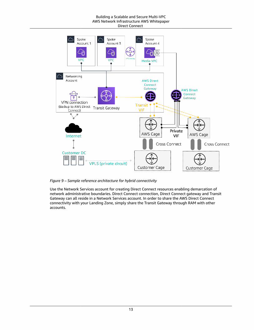
While the third option (transit VIF to Direct Connect gateway) might appear to be the best optionbecause that it lets you consolidate all your on-premises connectivity for a given AWS Region at a singlepoint (Transit Gateway) using a single BGP session per Direct Connect connection, given some of thelimits and considerations around option 3, we expect customers to leverage both option 2 and option3 for their Landing Zone connectivity requirements. Figure 9 illustrates a sample setup where TransitVIF is used as a default method for connecting to VPCs, and a private VIF is used for an edge use casewhere huge amount of data must be transferred from an on-premises DC to the media VPC. PrivateVIF is used to avoid Transit Gateway data transfer charges. As a best practice, you should have at leasttwo connections at two different Direct Connect locations for maximum redundancy, a total of fourconnections. You create one VIF per connection for a total of four private VIF’s and four transit VIFs. Youalso create a VPN as a backup connectivity to AWS Direct Connect connections.
12
Building a Scalable and Secure Multi-VPCAWS Network Infrastructure AWS Whitepaper
Direct Connect
Figure 9 – Sample reference architecture for hybrid connectivity
Use the Network Services account for creating Direct Connect resources enabling demarcation ofnetwork administrative boundaries. Direct Connect connection, Direct Connect gateway and TransitGateway can all reside in a Network Services account. In order to share the AWS Direct Connectconnectivity with your Landing Zone, simply share the Transit Gateway through RAM with otheraccounts.
13
Building a Scalable and Secure Multi-VPCAWS Network Infrastructure AWS Whitepaper
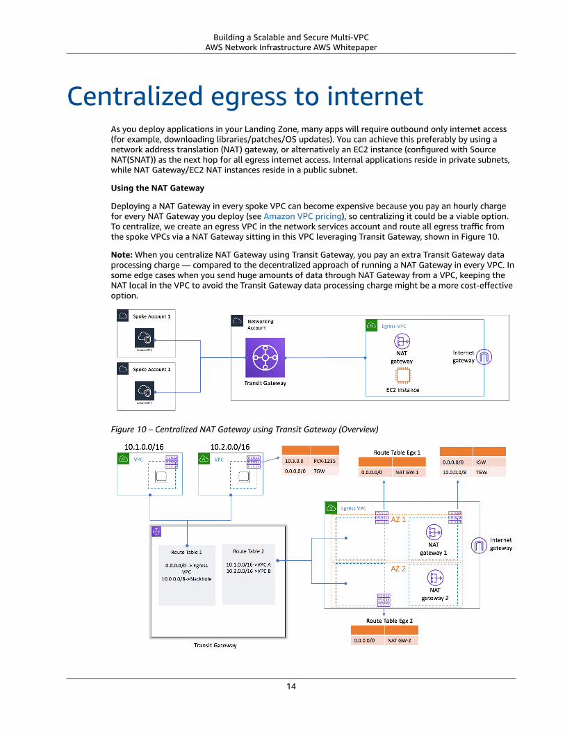
Centralized egress to internetAs you deploy applications in your Landing Zone, many apps will require outbound only internet access(for example, downloading libraries/patches/OS updates). You can achieve this preferably by using anetwork address translation (NAT) gateway, or alternatively an EC2 instance (configured with SourceNAT(SNAT)) as the next hop for all egress internet access. Internal applications reside in private subnets,while NAT Gateway/EC2 NAT instances reside in a public subnet.
Using the NAT Gateway
Deploying a NAT Gateway in every spoke VPC can become expensive because you pay an hourly chargefor every NAT Gateway you deploy (see Amazon VPC pricing), so centralizing it could be a viable option.To centralize, we create an egress VPC in the network services account and route all egress traffic fromthe spoke VPCs via a NAT Gateway sitting in this VPC leveraging Transit Gateway, shown in Figure 10.
Note: When you centralize NAT Gateway using Transit Gateway, you pay an extra Transit Gateway dataprocessing charge — compared to the decentralized approach of running a NAT Gateway in every VPC. Insome edge cases when you send huge amounts of data through NAT Gateway from a VPC, keeping theNAT local in the VPC to avoid the Transit Gateway data processing charge might be a more cost-effectiveoption.
Figure 10 – Centralized NAT Gateway using Transit Gateway (Overview)
14
Building a Scalable and Secure Multi-VPCAWS Network Infrastructure AWS Whitepaper
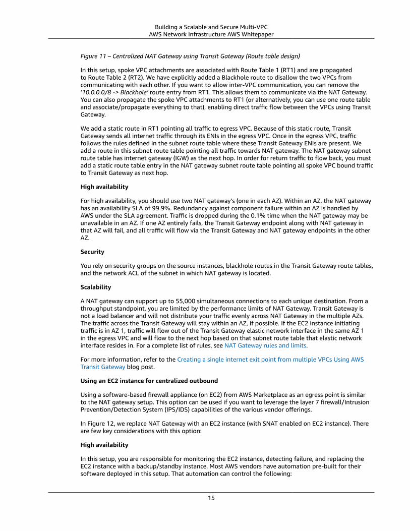
Figure 11 – Centralized NAT Gateway using Transit Gateway (Route table design)
In this setup, spoke VPC attachments are associated with Route Table 1 (RT1) and are propagatedto Route Table 2 (RT2). We have explicitly added a Blackhole route to disallow the two VPCs fromcommunicating with each other. If you want to allow inter-VPC communication, you can remove the‘10.0.0.0/8 -> Blackhole’ route entry from RT1. This allows them to communicate via the NAT Gateway.You can also propagate the spoke VPC attachments to RT1 (or alternatively, you can use one route tableand associate/propagate everything to that), enabling direct traffic flow between the VPCs using TransitGateway.
We add a static route in RT1 pointing all traffic to egress VPC. Because of this static route, TransitGateway sends all internet traffic through its ENIs in the egress VPC. Once in the egress VPC, trafficfollows the rules defined in the subnet route table where these Transit Gateway ENIs are present. Weadd a route in this subnet route table pointing all traffic towards NAT gateway. The NAT gateway subnetroute table has internet gateway (IGW) as the next hop. In order for return traffic to flow back, you mustadd a static route table entry in the NAT gateway subnet route table pointing all spoke VPC bound trafficto Transit Gateway as next hop.
High availability
For high availability, you should use two NAT gateway’s (one in each AZ). Within an AZ, the NAT gatewayhas an availability SLA of 99.9%. Redundancy against component failure within an AZ is handled byAWS under the SLA agreement. Traffic is dropped during the 0.1% time when the NAT gateway may beunavailable in an AZ. If one AZ entirely fails, the Transit Gateway endpoint along with NAT gateway inthat AZ will fail, and all traffic will flow via the Transit Gateway and NAT gateway endpoints in the otherAZ.
Security
You rely on security groups on the source instances, blackhole routes in the Transit Gateway route tables,and the network ACL of the subnet in which NAT gateway is located.
Scalability
A NAT gateway can support up to 55,000 simultaneous connections to each unique destination. From athroughput standpoint, you are limited by the performance limits of NAT Gateway. Transit Gateway isnot a load balancer and will not distribute your traffic evenly across NAT Gateway in the multiple AZs.The traffic across the Transit Gateway will stay within an AZ, if possible. If the EC2 instance initiatingtraffic is in AZ 1, traffic will flow out of the Transit Gateway elastic network interface in the same AZ 1in the egress VPC and will flow to the next hop based on that subnet route table that elastic networkinterface resides in. For a complete list of rules, see NAT Gateway rules and limits.
For more information, refer to the Creating a single internet exit point from multiple VPCs Using AWSTransit Gateway blog post.
Using an EC2 instance for centralized outbound
Using a software-based firewall appliance (on EC2) from AWS Marketplace as an egress point is similarto the NAT gateway setup. This option can be used if you want to leverage the layer 7 firewall/IntrusionPrevention/Detection System (IPS/IDS) capabilities of the various vendor offerings.
In Figure 12, we replace NAT Gateway with an EC2 instance (with SNAT enabled on EC2 instance). Thereare few key considerations with this option:
High availability
In this setup, you are responsible for monitoring the EC2 instance, detecting failure, and replacing theEC2 instance with a backup/standby instance. Most AWS vendors have automation pre-built for theirsoftware deployed in this setup. That automation can control the following:
15
Building a Scalable and Secure Multi-VPCAWS Network Infrastructure AWS Whitepaper
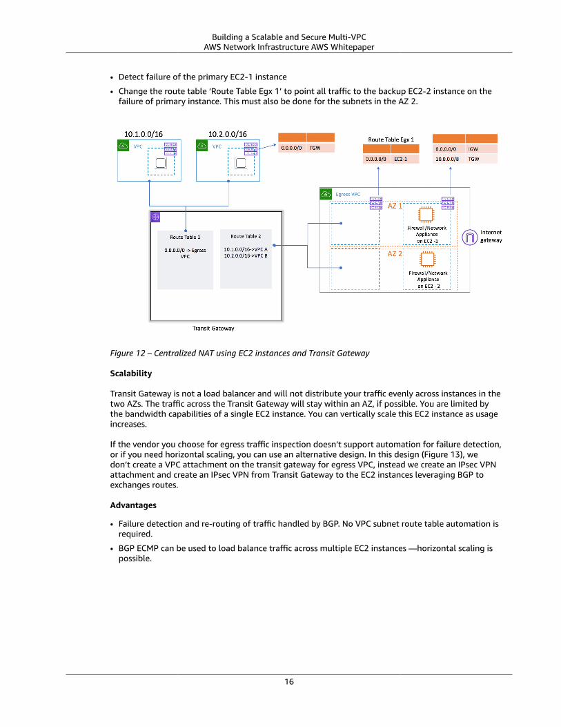
• Detect failure of the primary EC2-1 instance
• Change the route table ‘Route Table Egx 1’ to point all traffic to the backup EC2-2 instance on thefailure of primary instance. This must also be done for the subnets in the AZ 2.
Figure 12 – Centralized NAT using EC2 instances and Transit Gateway
Scalability
Transit Gateway is not a load balancer and will not distribute your traffic evenly across instances in thetwo AZs. The traffic across the Transit Gateway will stay within an AZ, if possible. You are limited bythe bandwidth capabilities of a single EC2 instance. You can vertically scale this EC2 instance as usageincreases.
If the vendor you choose for egress traffic inspection doesn’t support automation for failure detection,or if you need horizontal scaling, you can use an alternative design. In this design (Figure 13), wedon’t create a VPC attachment on the transit gateway for egress VPC, instead we create an IPsec VPNattachment and create an IPsec VPN from Transit Gateway to the EC2 instances leveraging BGP toexchanges routes.
Advantages
• Failure detection and re-routing of traffic handled by BGP. No VPC subnet route table automation isrequired.
• BGP ECMP can be used to load balance traffic across multiple EC2 instances —horizontal scaling ispossible.
16
Building a Scalable and Secure Multi-VPCAWS Network Infrastructure AWS Whitepaper
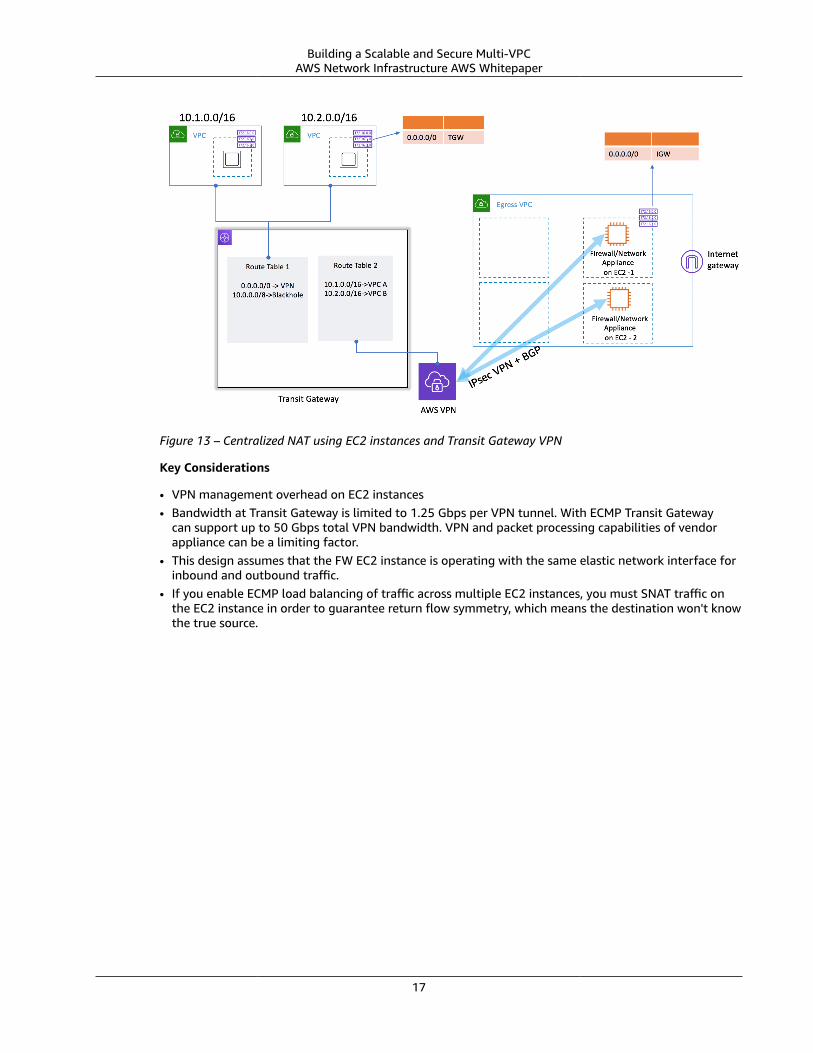
Figure 13 – Centralized NAT using EC2 instances and Transit Gateway VPN
Key Considerations
• VPN management overhead on EC2 instances• Bandwidth at Transit Gateway is limited to 1.25 Gbps per VPN tunnel. With ECMP Transit Gateway
can support up to 50 Gbps total VPN bandwidth. VPN and packet processing capabilities of vendorappliance can be a limiting factor.
• This design assumes that the FW EC2 instance is operating with the same elastic network interface forinbound and outbound traffic.
• If you enable ECMP load balancing of traffic across multiple EC2 instances, you must SNAT traffic onthe EC2 instance in order to guarantee return flow symmetry, which means the destination won't knowthe true source.
17
Building a Scalable and Secure Multi-VPCAWS Network Infrastructure AWS Whitepaper
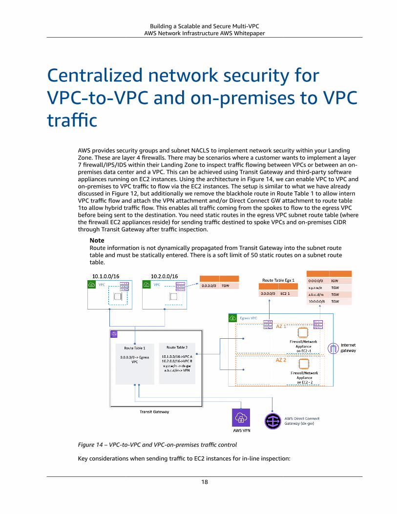
Centralized network security forVPC-to-VPC and on-premises to VPCtraffic
AWS provides security groups and subnet NACLS to implement network security within your LandingZone. These are layer 4 firewalls. There may be scenarios where a customer wants to implement a layer7 firewall/IPS/IDS within their Landing Zone to inspect traffic flowing between VPCs or between an on-premises data center and a VPC. This can be achieved using Transit Gateway and third-party softwareappliances running on EC2 instances. Using the architecture in Figure 14, we can enable VPC to VPC andon-premises to VPC traffic to flow via the EC2 instances. The setup is similar to what we have alreadydiscussed in Figure 12, but additionally we remove the blackhole route in Route Table 1 to allow internVPC traffic flow and attach the VPN attachment and/or Direct Connect GW attachment to route table1to allow hybrid traffic flow. This enables all traffic coming from the spokes to flow to the egress VPCbefore being sent to the destination. You need static routes in the egress VPC subnet route table (wherethe firewall EC2 appliances reside) for sending traffic destined to spoke VPCs and on-premises CIDRthrough Transit Gateway after traffic inspection.
NoteRoute information is not dynamically propagated from Transit Gateway into the subnet routetable and must be statically entered. There is a soft limit of 50 static routes on a subnet routetable.
Figure 14 – VPC-to-VPC and VPC-on-premises traffic control
Key considerations when sending traffic to EC2 instances for in-line inspection:
18
Building a Scalable and Secure Multi-VPCAWS Network Infrastructure AWS Whitepaper
• Additional Transit Gateway data processing charges
• Traffic must go through two additional hops (EC2 instance and Transit Gateway)
• Potential for bandwidth and performance bottlenecks
• Additional complexity of maintaining, managing, and scaling EC2 instances:
• Detecting failure and failing over to standby
• Tracking usage and horizontal/vertical scaling
• Firewall configuration, patch management
• Source Network Address Translation (SNAT) of traffic when load balancing to guarantee symmetricflow
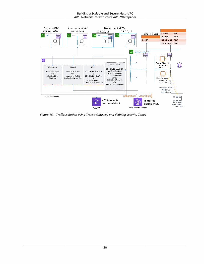
You should be selective in what traffic passes via these EC2 instances. One way to proceed is to definesecurity zones and inspect traffic between untrusted zones. An untrusted zone can be a remote sitemanaged by a 3rd party, a vendor VPC you don’t control/trust, or a sandbox/dev VPC, which has morerelaxed security framework compared to rest of your environment. Figure 15 enables direct traffic flowbetween trusted networks while inspecting traffic flow to/from untrusted networks using in-line EC2instances. We created three zones in this example:
• Untrusted Zone — This is for any traffic coming from the ‘VPN to remote untrusted site’ or the 3rdparty vendor VPC.
• Prod Zone — This contains traffic from the production VPC and on-premises customer DC.
• Dev Zone —This contains traffic from the two development VPCs.
The following are sample rules we define for communication across zones:
1. Untrusted Zone Prod Zone - Communication not allowed
2. Prod Zone Dev Zone - Communication allowed via EC2 FW appliances in egress VPC
3. Untrusted Zone Dev Zone - Communication allowed via EC2 FW appliances in egress VPC
4. Prod Zone Prod Zone and Dev Zone Dev Zone – Direct communication via Transit Gateway
This is a setup has three security zones, but you might have more. You can use multiple route tablesand blackhole routes to achieve security isolation and optimal traffic flow. Choosing the right zones isdependent on your overall Landing Zone design strategy (account structure, VPC design). You can havezones to enable isolation between BU, applications, environments, etc.
In this example, we terminate the untrusted remote VPN on Transit Gateway and send all traffic tosoftware FW appliances on EC2 for inspection. Alternatively, you can terminate these VPNs directly onthe EC2 instances instead of Transit Gateway. With this approach, the untrusted VPN traffic never directlyinteracts with Transit Gateway. The number of hops in the traffic flow reduces by 1, and you save onAWS VPN costs. To enable dynamic route exchanges (for Transit Gateway to learn the CIDR of the remoteVPN via BGP), the firewall instances should be connected to Transit Gateway via VPN. In the native TGWattachment model, you must add static routes in the TGW route table for VPN CIDE with the next hopas the egress/security VPC. In our setup (Figure15), we have a default route to egress VPC for all trafficso we don’t have to explicitly add any specific static routes. With this approach you move away from afully managed Transit Gateway VPN termination endpoint to a self-managed EC2 instance, adding VPNmanagement overhead as well as additional load on the EC2 instance in terms of compute and memory.
19
Building a Scalable and Secure Multi-VPCAWS Network Infrastructure AWS Whitepaper
Figure 15 – Traffic isolation using Transit Gateway and defining security Zones
20
Building a Scalable and Secure Multi-VPCAWS Network Infrastructure AWS Whitepaper
Hybrid DNS
DNS
When you launch an instance into a nondefault VPC, AWS provides the instance with a private DNShostname (and potentially a public DNS hostname) depending on the DNS attributes you specify forthe VPC and if your instance has a public IPv4 address. When the ‘enableDnsSupport’ attribute is set totrue, you get a DNS resolution within the VPC from Route 53 Resolver (+2 IP offset to the VPC CIDR).By default, Route 53 Resolver answers DNS queries for VPC domain names such as domain names forEC2 instances or Elastic Load Balancing load balancers. With VPC peering, hosts in one VPC can resolvepublic DNS hostnames to private IP addresses for instances in peered VPCs, provided the option to do sois enabled. The same is applicable for VPCs connected via AWS Transit Gateway. For more informationsee, Enabling DNS Resolution Support for a VPC Peering Connection.
If you want to map your instances to a custom domain name, you can use Amazon Route 53 to createa custom DNS-to-IP-mapping record. An Amazon Route 53 hosted zone is a container that holdsinformation about how you want Amazon Route 53 to respond to DNS queries for a domain and itssubdomains. Public Hosted Zones contain DNS information that is resolvable over the public internetwhile Private Hosted Zones are a specific implementation that only presents information to VPCs thathave been attached to the specific private hosted zone. In a Landing Zone setup where you have multipleVPCs/accounts, you can associate a single private hosted zone with multiple VPCs across AWS accountsand across Regions. The end hosts in the VPCs use their respective Route 53 Resolver IP (+2 offset theVPC CIDR) as the name server for DNS queries. The Route 53 Resolver in VPC accepts DNS queries onlyfrom resources within a VPC.
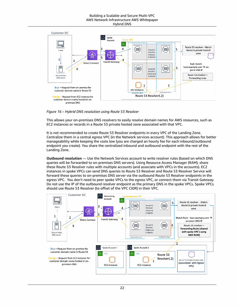
Hybrid DNSCoordinating DNS resolution between AWS Landing Zone setup and on-premises resources is one of themost critical pieces in a hybrid network. Customers implementing hybrid environments usually have aDNS resolution system already in place, and they want a DNS solution that works in tandem with theircurrent system. When you integrate DNS for the VPCs in an AWS Region with DNS for your network,you need a Route 53 Resolver inbound endpoint (for DNS queries that you're forwarding to your VPCs)and a Route 53 Resolver outbound endpoint (for queries that you're forwarding from your VPCs to yournetwork). As shown in Figure 16, you can configure outbound Resolver endpoints to forward queries itreceives from EC2 instances in your VPCs to DNS servers on your network. To forward selected queries,from a VPC to on-premises, create Route 53 Resolver rules that specify the domain names for the DNSqueries that you want to forward (such as example.com), and the IP addresses of the DNS resolvers onyour network where you want to forward the queries. For inbound queries from on-premises to Route 53hosted zones, DNS servers on your network can forward queries to inbound Resolver endpoints in aspecified VPC.
21
Building a Scalable and Secure Multi-VPCAWS Network Infrastructure AWS Whitepaper
Hybrid DNS
Figure 16 – Hybrid DNS resolution using Route 53 Resolver
This allows your on-premises DNS resolvers to easily resolve domain names for AWS resources, such asEC2 instances or records in a Route 53 private hosted zone associated with that VPC.
It is not recommended to create Route 53 Resolver endpoints in every VPC of the Landing Zone.Centralize them in a central egress VPC (in the Network services account). This approach allows for bettermanageability while keeping the costs low (you are charged an hourly fee for each inbound/outboundendpoint you create). You share the centralized inbound and outbound endpoint with the rest of theLanding Zone.
Outbound resolution — Use the Network Services account to write resolver rules (based on which DNSqueries will be forwarded to on-premises DNS servers). Using Resource Access Manager (RAM), sharethese Route 53 Resolver rules with multiple accounts (and associate with VPCs in the accounts). EC2instances in spoke VPCs can send DNS queries to Route 53 Resolver and Route 53 Resolver Service willforward these queries to on-premises DNS server via the outbound Route 53 Resolver endpoints in theegress VPC. You don’t need to peer spoke VPCs to the egress VPC, or connect them via Transit Gateway.Do not use the IP of the outbound resolver endpoint as the primary DNS in the spoke VPCs. Spoke VPCsshould use Route 53 Resolver (to offset of the VPC CIDR) in their VPC.
22
Building a Scalable and Secure Multi-VPCAWS Network Infrastructure AWS Whitepaper
Hybrid DNS
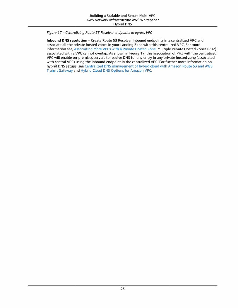
Figure 17 – Centralizing Route 53 Resolver endpoints in egress VPC
Inbound DNS resolution – Create Route 53 Resolver inbound endpoints in a centralized VPC andassociate all the private hosted zones in your Landing Zone with this centralized VPC. For moreinformation see, Associating More VPCs with a Private Hosted Zone. Multiple Private Hosted Zones (PHZ)associated with a VPC cannot overlap. As shown in Figure 17, this association of PHZ with the centralizedVPC will enable on-premises servers to resolve DNS for any entry in any private hosted zone (associatedwith central VPC) using the inbound endpoint in the centralized VPC. For further more information onhybrid DNS setups, see Centralized DNS management of hybrid cloud with Amazon Route 53 and AWSTransit Gateway and Hybrid Cloud DNS Options for Amazon VPC.
23
Building a Scalable and Secure Multi-VPCAWS Network Infrastructure AWS Whitepaper
Interface VPC endpoints
Centralized access to VPC privateendpoints
A VPC endpoint allows you to privately connect your VPC to supported AWS services without requiringan internet gateway or a NAT device. Instances in your VPC do not require public IP addresses tocommunicate with AWS service endpoints with this interface endpoint. Traffic between your VPC andother services does not leave the AWS network backbone. Two types of endpoints can currently beprovisioned: Interface Endpoints (powered by AWS PrivateLink) and Gateway Endpoints. Gatewayendpoints are free to provision, and there is not a strong use case for centralization.
Interface VPC endpointsAn interface endpoint consists of one or more elastic network interfaces with a private IP address thatserves as an entry point for traffic destined to a supported AWS service. When you provision an interfaceendpoint, a cost is incurred by users for every hour the endpoint is running. By default, you create aninterface endpoint in every VPC from which you want to access the AWS service. This can be expensiveand difficult to manage in the Landing Zone setup where a customer wants to interact with a specificAWS service across multiple VPCs. To avoid this, you can host the interface endpoints in one centralizedVPC. All the spoke VPCs will use these centralized endpoints.
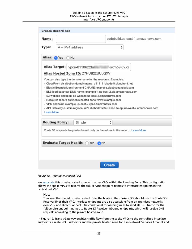
When you create a VPC endpoint to an AWS service, you can enable Private DNS. When enabled, thesetting creates an AWS managed Route 53 private hosted zone (PHZ) which enables the resolutionof public AWS service endpoint to the private IP of the interface endpoint. The managed PHZ onlyworks within the VPC with the interface endpoint. In our setup, when we want spoke VPCs to be ableto resolve VPC endpoint DNS hosted in a centralized VPC, the managed PHZ won’t work. To overcomethis, disable the option that automatically creates the private DNS when an interface endpoint is created.Alternatively, you can manually create a Route 53 PHZ and add Alias record with the full AWS serviceendpoint name pointing to the interface endpoint as shown in Figure 18.
24
Building a Scalable and Secure Multi-VPCAWS Network Infrastructure AWS Whitepaper
Interface VPC endpoints
Figure 18 – Manually created PHZ
We associate this private hosted zone with other VPCs within the Landing Zone. This configurationallows the spoke VPCs to resolve the full-service endpoint names to interface endpoints in thecentralized VPC.
NoteTo access the shared private hosted zone, the hosts in the spoke VPCs should use the Route 53Resolver IP of their VPC. Interface endpoints are also accessible from on-premises networksover VPN and Direct Connect. Use conditional forwarding rules to send all DNS traffic for thefull-service endpoint names to Route 53 Resolver inbound endpoints, which will resolve DNSrequests according to the private hosted zone.
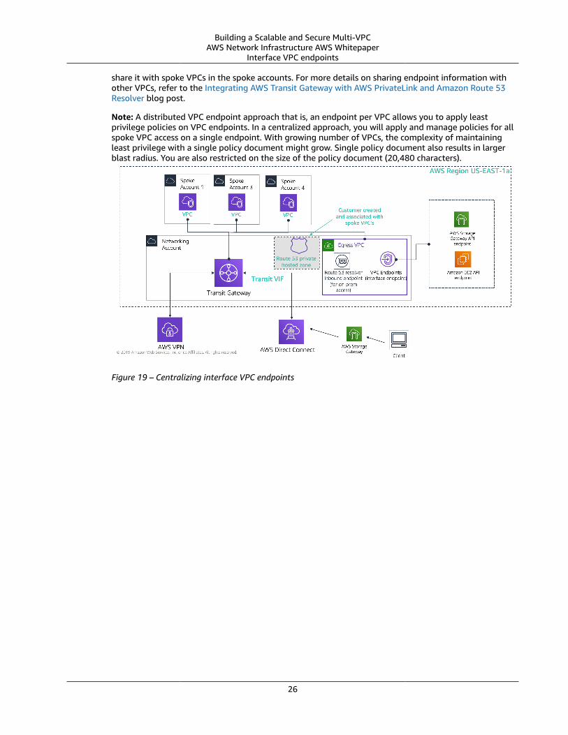
In Figure 19, Transit Gateway enables traffic flow from the spoke VPCs to the centralized interfaceendpoints. Create VPC Endpoints and the private hosted zone for it in Network Services Account and
25
Building a Scalable and Secure Multi-VPCAWS Network Infrastructure AWS Whitepaper
Interface VPC endpoints
share it with spoke VPCs in the spoke accounts. For more details on sharing endpoint information withother VPCs, refer to the Integrating AWS Transit Gateway with AWS PrivateLink and Amazon Route 53Resolver blog post.
Note: A distributed VPC endpoint approach that is, an endpoint per VPC allows you to apply leastprivilege policies on VPC endpoints. In a centralized approach, you will apply and manage policies for allspoke VPC access on a single endpoint. With growing number of VPCs, the complexity of maintainingleast privilege with a single policy document might grow. Single policy document also results in largerblast radius. You are also restricted on the size of the policy document (20,480 characters).
Figure 19 – Centralizing interface VPC endpoints
26
Building a Scalable and Secure Multi-VPCAWS Network Infrastructure AWS Whitepaper
ConclusionAs you scale your usage of AWS and deploy applications in the AWS Landing Zone, the number of VPCsand networking components increases. This whitepaper explained how we can manage this growinginfrastructure ensuring scalability, high availability, and security while keeping costs low. Making theright design decisions when leveraging services like Transit Gateway, Shared VPC, AWS Direct Connect,VPC endpoints, and third-party software appliances becomes critical. It is important to understand thekey considerations of each approach and work backwards from your requirements and analyze as towhich option or combination of options fit you best.
27
Building a Scalable and Secure Multi-VPCAWS Network Infrastructure AWS Whitepaper
ContributorsThe following individuals contributed to this document:
• Sidhartha Chauhan, Solutions Architect, Amazon Web Services• Amir Abu-akeel, Cloud Infrastructure Architect, Amazon Web Services• Sohaib Tahir, Solutions Architect, Amazon Web Services
28
Building a Scalable and Secure Multi-VPCAWS Network Infrastructure AWS Whitepaper
Document HistoryTo be notified about updates to this whitepaper, subscribe to the RSS feed.
update-history-change update-history-description update-history-date
Minor update (p. 10) Corrected text to match theoptions illustrated in Figure 7.
June 10, 2020
Initial publication (p. 29) Whitepaper published. November 15, 2019
29
Building a Scalable and Secure Multi-VPCAWS Network Infrastructure AWS Whitepaper
NoticesCustomers are responsible for making their own independent assessment of the information in thisdocument. This document: (a) is for informational purposes only, (b) represents current AWS productofferings and practices, which are subject to change without notice, and (c) does not create anycommitments or assurances from AWS and its affiliates, suppliers, or licensors. AWS products or servicesare provided “as is” without warranties, representations, or conditions of any kind, whether express orimplied. The responsibilities and liabilities of AWS to its customers are controlled by AWS agreements,and this document is not part of, nor does it modify, any agreement between AWS and its customers.
© 2019 Amazon Web Services, Inc. or its affiliates. All rights reserved.
30


![[AWSマイスターシリーズ] Amazon VPC](https://img.dokumen.tips/doc/110x75/55856c23d8b42a422c8b46bc/aws-amazon-vpc.jpg)


![[AWSマイスターシリーズ] Amazon Virtual Private Cloud (VPC)](https://img.dokumen.tips/doc/110x75/54831431b47959ce0c8b4943/aws-amazon-virtual-private-cloud-vpc.jpg)
