Embed Size (px)
Citation preview

Bayu-Undan Gas Recycle Project
PHILLIPS PETROLEUM (91-12) PTY LTD
A.C.N. 064 963 346
i
Design Guide
System Valving and Isolation Philosophy
Document No.: BUGEN-00-010-N01-0103
TIGA JOINT VENTURE Fluor Australia Pty Ltd ACN: 004 511 942 Worley Limited ACN: 001 279 812
REV DESCRIPTION Originator Checker Discipline Approval
TIGA Approval
DATE Client Acceptance
DATE
A Issued For Review G Turner J Hathway 25/11/97
B Reissued for Review G Turner J Hathway 17/12/97
C Issued for Client Approval G Turner P Broderick P Broderick M Reilly 30/1/98
D Reissued for Client Approval G Turner P Broderick P Broderick M Reilly 27/5/98
0 Approved for Design P Broderick G Turner P Broderick M Reilly 11/6/98 F Radcliffe 12/6/98
1 Reissued, Approved for Design
P Broderick P Broderick I McD. 22/9/98
2 Reissued, Approved for Design
J Wong P Broderick P Broderick
3 Reissued, Approved for Design
S kulkarni P Broderick P Broderick T Holy 20/09/00
4 Reissued, Approved for Design
S Kulkarni P Broderick P Broderick M Kyle 21/11/01

Bayu-Undan Gas Recycle Project System Valving and Isolation Philosophy – Design Guide
ii
SYNOPSIS
This Design Guide addresses the philosophy and requirements for system valving and isolation for the Bayu-Undan Upstream Project. Guidelines are given for the type of valving and isolation required in various situations and for various types of equipment.
These guidelines are intended for use in development of the P&IDs and the piping design for the project.

Bayu Undan Gas Recycle Project System Valving and Isolation Philosophy – Design Guide
BUGEN-00-010-N01-0103 Rev 3 iii
CONTENTS Cover ......................................................................................................................................... i
Synopsis ..................................................................................................................................... ii
Contents (2 Pages) ..................................................................................................................... iii
1 ISOLATION PHILOSOPHY ....................................................................................... 1
1.1 Introduction ................................................................................................................... 1
1.2 Objectives ....................................................................................................................... 1
2 DEFINITIONS .............................................................................................................. 2
2.1 Hazardous Service ......................................................................................................... 2
2.2 Positive Isolation ............................................................................................................ 2
2.3 High Integrity Isolation ................................................................................................ 2
2.4 General Isolation ........................................................................................................... 2
2.5 High/Low Pressure ........................................................................................................ 2
3 SYSTEM ISOLATION AND VALVING REQUIREMENTS ................................. 3
3.1 General Guidelines ........................................................................................................ 3
3.2 Train Isolation ............................................................................................................... 4
3.3 Flowline Isolation .......................................................................................................... 4
3.4 Isolation of Instrumentation ......................................................................................... 4
3.5 Means of Isolation ......................................................................................................... 5
3.6 Securing Valve Position ................................................................................................ 6
3.7 Vessel Vents ................................................................................................................... 7
3.8 Vessel and Piping Drains .............................................................................................. 7
3.9 Equipment Vents and Drains ....................................................................................... 8
3.10 Heating Medium Isolation ............................................................................................ 8
3.11 Vents and Drains for freeing hydrocarbons ............................................................... 8
3.12 Lethal Service ................................................................................................................ 8
4 INSULATION ISSUES ................................................................................................. 9
4.1 Extent of Insulation on Drains, Vent and Relief lines ................................................ 9
5 TYPICAL STANDARD DETAILS ........................................................................... 10
ATTACHMENTS A. TYPICAL STANDARDS DETAILS ............................................................................... (2 Pages)
B. GUIDELINES FOR USE OF OPTIONS FOR POSITIVE ISOLATION ........................ (2 Pages)
C. HEATING MEDIUM ISOLATION .............................................................................. (18 Pages)
Bayu Undan Gas Recycle Project System Valving and Isolation Philosophy – Design Guide
BUGEN-00-010-N01-0103 Rev 4 Page 1 of 11
1 ISOLATION PHILOSOPHY
1.1 Introduction This design guide describes the methods to be used in making provision to completely isolate equipment or sections of plant to permit safe operation and to provide access for maintenance and inspection. Process sections shall also be isolated for leak testing during commissioning.
The design guides shall apply to all process and utility systems on the Bayu-Undan Upstream Project including packaged equipment - any deviation from these guidelines must be approved by the TIGA Lead Process Engineer/General Engineering Manager and the EPC Engineering Manager and be specifically noted on the P&ID’s.
In general, it must be possible to isolate all equipment separately or commonly within a process system except those systems in non-hydrocarbon service where a hazardous condition will definitely not exist.
Isolation shall be accomplished by the use of block valves and/or the insertion of spectacle blinds or spades, or the removal of spool pieces and the installation of blind flanges. Location of isolation to enable maintenance and inspection is generally dependent on the extent of shutdown, hazardous nature of the contained fluids and pressure rating of the piping system.
1.2 Objectives The objectives of the following design guide are :
• to define safe isolation methods, draining, purging and venting provisions for on-line plant containing process and utility liquids and gases, so that operation, maintenance and inspection can take place with minimum plant shutdown.
• to ensure necessary facilities are incorporated in the design.
• to minimise cost consistent with maintaining project safety objectives.

Bayu Undan Gas Recycle Project System Valving and Isolation Philosophy – Design Guide
BUGEN-00-010-N01-0103 Rev 4 Page 2 of 11
2 DEFINITIONS
2.1 Hazardous Service The definition of Hazardous Service is as follows:
• fluids above their Autoignition temperature (AIT).
• flammable liquids flashing on leakage that could form a vapour cloud, including NG liquids.
• flammable gases which may form a vapour cloud on leakage.
• fluids liable to cause a hazard by blockage due to hydrate formation or solids deposition.
• fluids with a flash point below 60 ºC, including methanol.
• toxic substances which can cause serious irreversible damage unless prompt restorative measures are taken eg. high H2S gas.
• heating medium fluids (above 100 ºC)
• fluids at high pressure (see 2.5)
2.2 Positive Isolation Positive isolation is defined as a method of guaranteeing 100 % physical segregation of a hazard or contamination source from personnel and/or product inventory.
2.3 High Integrity Isolation High integrity isolation provides a method of providing the highest possible level of segregation without a 100% guarantee.
2.4 General Isolation General isolation is a means of providing a level of segregation for non-hazardous services and low pressure hazardous service.
2.5 High/Low Pressure High pressure service is classed as any service with a maximum system pressure of 20 barg or greater. Systems with maximum system pressures of less than 20 barg are classified as low pressure.
Note:
When applying the definition of high pressure (>20barg) in Table 3.1, double block and bleed isolation would be required. For hydrocarbon liquid systems, single valve isolation is permitted up to 55barg operating pressure e.g. condensate system downstream of Second Stage Separator. However, if the equipment is considered to require a high frequency of maintenance, double block and bleed isolation may be provided e.g. Coalescer Guard Filters D-V1403A/B. Level or pressure instrument isolation is unaffected by this (refer to sections 3.4.1/3.4.2)

Bayu Undan Gas Recycle Project System Valving and Isolation Philosophy – Design Guide
BUGEN-00-010-N01-0103 Rev 4 Page 3 of 11
3 SYSTEM ISOLATION AND VALVING REQUIREMENTS
3.1 General Guidelines The following Table 3.1 provides general guidelines on the application of the various isolation methods defined in section 2.0, as well as the method of achieving the isolation.
TABLE 3.1 : ISOLATION TYPES, APPLICATION AND METHOD
Isolation Type/Application Method
a) Positive Isolation
Used where no leakage can be tolerated e.g.
• all confined space entries
• to prevent cross-contamination of utilities with process
• to isolate a train from other hazardous process/utilities for purpose of overhaul/inspection.
a) Positive isolation can be achieved by either of the following:
• removable spool
• spade and spacer
• spectacle blind
b) High Integrity Isolation
• where equipment is to be isolated from live high pressure process for extended periods of maintenance ( i.e. longer than one shift, or where maintenance task is not completed without crossing over shifts).
• where equipment is to be isolated from a large inventory (e.g. a pipeline)
• Expanded through conduit gate valves may be used in certain applications with agreement from PPCo e.g. manual isolation valves on gas metering runs.
• Single valve isolation may be considered and applied as long as the external high pressure is depressurised to below 20barg prior to isolation e.g. inlet to Dry Gas Filter Coalescers D-V1111/D-V1121 where upstream Glycol Contactors and downstream Cold Process Exchangers are depressurised to below 20barg, thus allowing single valve isolation for maintenance of the Dry Gas Filter Coalescers. Exception is maintenance of relief values, see section 3.4.3.
b) Double block & bleed (DB&B)
2 separate valves & bleed
c) General Isolation
Used where a level of segregation is required for non-hazardous services or for low pressure hazardous service e.g. hot oil.
Single high performance butterfly valves (e.g. Vanessa type) are acceptable in heating medium & cooling medium service.
c) General isolation can be achieved by either of the following:
• Single block valve
• Single block and bleed

Bayu Undan Gas Recycle Project System Valving and Isolation Philosophy – Design Guide
BUGEN-00-010-N01-0103 Rev 4 Page 4 of 11
3.2 Train Isolation Dedicated isolation valves will not be provided for unspared equipment within a train except:
i) where the equipment can be bypassed and the process allowed to continue in operation.
ii) to reduce system size to a reasonable value with respect to inventory vented (loss of product, environmental considerations), and with respect to gas freeing and purging requirements.
Equipment spared within the train shall be provided with isolation at the inlet and outlet in accordance with 3.1 above.
3.3 Flowline Isolation Isolation of headers will be provided by double block and bleed isolation on each flowline to allow isolation of individual flowlines and wells to be achieved.
3.4 Isolation of Instrumentation
3.4.1 Level Instrumentation Level instrumentation on all hazardous service vessels shall have integral double block and bleed (monoflange) isolation valves. This philosophy is adopted for reasons of providing commonality in maintenance operations (acknowledging that single valve isolation might be acceptable for low pressure hazardous applications). For non-hazardous service, a single block valve is adequate (normal piping specification valve shall be used). Refer to standard details in Attachment A.
3.4.2 Pressure Instruments All pressure instrumentation in hazardous service will be provided with an integral double block and bleed (monoflange) assembly as the process isolation. This philosophy is adopted for reasons of providing commonality in maintenance operations (acknowledging that single valve isolation might be acceptable for low pressure hazardous applications). For non-hazardous service, an integral single block and bleed (monoflange) assembly is adequate. Refer to standard details in Attachment A.
3.4.3 Relief Valves Spared relief valve installations will be provided with a sequenced key interlock system fitted to the inlet and outlet valves. Refer to standard details in Attachment A. A single isolation valve is provided upstream of the relief valve. For high pressure systems, the relief valve may be removed for maintenance as long as the single isolation valve is not passing (as observed via the bleed valve between the isolation valve and relief valve). It is not necessary to depressurise the process system to less than 20 barg prior to removal of the relief valve.
A similar philosophy (single upstream isolation valve and bleed) may be adopted for pressure control valves to flare in high pressure systems.
Unspared relief valve installations (whether single or multiple) will not have an upstream isolation valve installed. For some unspared relief valve installations, space and flanged connections will be provided for addition of an isolation valve in future. In such cases, suitable pipe branches, for supply to and discharge from a potential (future) spare relief valve will also be installed (refer to Flare, Relief and Blowdown System Design Philosophy Document No. BUGEN-00-10-R02-2002 for such instances). These piping arrangements will be fitted with a blind flange for the future relief valve
Bayu Undan Gas Recycle Project System Valving and Isolation Philosophy – Design Guide
BUGEN-00-010-N01-0103 Rev 4 Page 5 of 11
upstream connection and a normally closed valve for the downstream connection (to avoid platform shutdown for installation of the relief valve).
3.5 Means of Isolation
3.5.1 Valves Manual or ESD valves are acceptable for use in double block and bleed isolation, except for fail open valves (unless the latter are provided with a mechanical “hold closed” system.
When relief valves connected to the HP or LP Flare/Vent Headers are removed, a blind flange will be installed on the upstream side of the downstream isolation valve as part of the operating procedures.
3.5.2 Spectacle Blinds, Spades and Spacers Spades and spacers (including spectacle blinds) shall be used in accordance with Piping Specifications (refer also to Table 3.2).
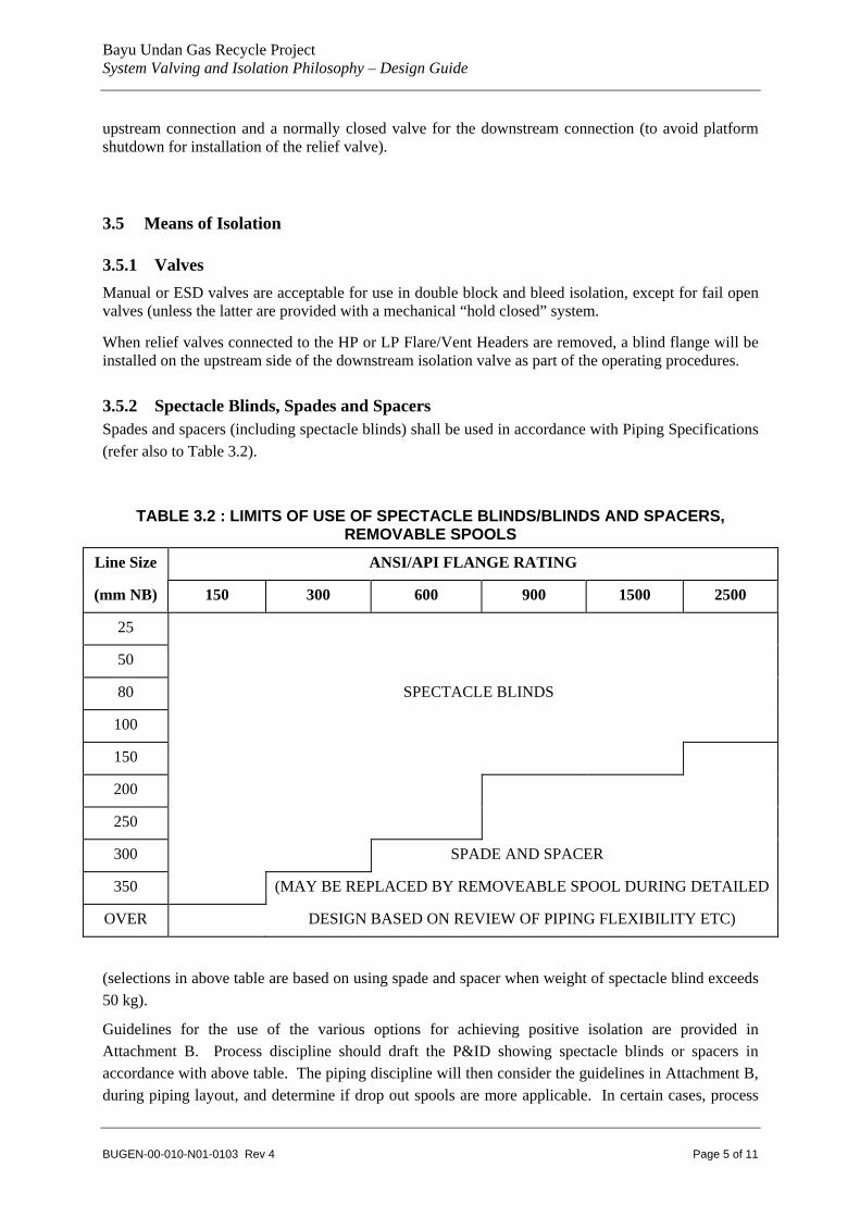
TABLE 3.2 : LIMITS OF USE OF SPECTACLE BLINDS/BLINDS AND SPACERS, REMOVABLE SPOOLS
Line Size ANSI/API FLANGE RATING
(mm NB) 150 300 600 900 1500 2500
25
50
80 SPECTACLE BLINDS
100
150
200
250
300 SPADE AND SPACER
350 (MAY BE REPLACED BY REMOVEABLE SPOOL DURING DETAILED
OVER DESIGN BASED ON REVIEW OF PIPING FLEXIBILITY ETC)
(selections in above table are based on using spade and spacer when weight of spectacle blind exceeds 50 kg).
Guidelines for the use of the various options for achieving positive isolation are provided in Attachment B. Process discipline should draft the P&ID showing spectacle blinds or spacers in accordance with above table. The piping discipline will then consider the guidelines in Attachment B, during piping layout, and determine if drop out spools are more applicable. In certain cases, process
Bayu Undan Gas Recycle Project System Valving and Isolation Philosophy – Design Guide
BUGEN-00-010-N01-0103 Rev 4 Page 6 of 11
should draft the P&ID showing drop out spools without waiting for feedback from piping layout. See Section 3.5.3 below for such cases.
3.5.3 Spool Pieces Spool pieces may be used when positive isolation is necessary for maintenance purposes. Spool pieces will be clearly defined on the P&ID’s. This type of isolation requirement may be necessary in the following areas :
• When wafer type butterfly valves are used to isolate heat exchangers, an additional flange must be provided between the valve and the spool piece to allow for spool removal without disturbing the butterfly valve.
• For compressor maintenance, spool pieces are required on the suction and discharge nozzles to provide positive isolation.
• Vessel outlet to relief valve (to avoid spade or spectacle blind in the relief route).
• Vessel outlet (gas) which may be used as a manway.
• PCHEs connections, for ease of removal.
• Pumps (subject to guidelines in Attachment B).
Piping shall be designed to permit practical removal and reinstallation of spools via provision of sufficient pipe flexibility and appropriate mechanical handling procedures.
3.6 Securing Valve Position Securing of valves in position is defined as a method of locking the valves to avoid inadvertent opening/closing. Securing of valve position shall be achieved by use of proprietary key locking devices (identified as ILO/ILC on P&ID’s), or “car-sealing” (identified as CSO/CSC on P&ID’s), together with written operating procedures.
Secured valves will be provided on systems where, for safe operation, valves are required to operate in either a fixed open or closed position.
The following applications of valve position securing are proposed and will be indicated on the P&ID’s :
a) Within fire protection systems, valves on firewater distribution, and local foam distribution systems shall be car-sealed open/closed as appropriate.
b) Isolation valves for shutdown instruments shall be car-sealed open.
c) Duplicated relief devices for vessels and systems installed to allow on-line maintenance shall have captive key type interlocks on the inlet and outlet valves interlocked in the open position. The spare relief valve set will have the upstream isolation valve interlocked in the closed position, and the downstream valve interlocked in the open position. When maintenance of one of the relief valves is required the inlet and outlet block valves on the relief valve to be maintained will be interlocked closed.
d) Where blowdown valves are provided with block valves theses shall be car-sealed open.
e) Block valves downstream of single relief valves shall be car-sealed open. No upstream block valve is allowed.
Bayu Undan Gas Recycle Project System Valving and Isolation Philosophy – Design Guide
BUGEN-00-010-N01-0103 Rev 4 Page 7 of 11
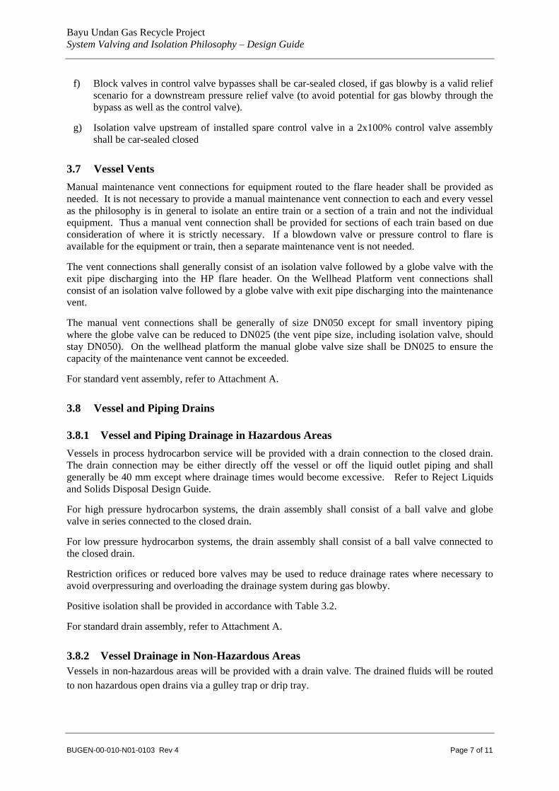
f) Block valves in control valve bypasses shall be car-sealed closed, if gas blowby is a valid relief scenario for a downstream pressure relief valve (to avoid potential for gas blowby through the bypass as well as the control valve).
g) Isolation valve upstream of installed spare control valve in a 2x100% control valve assembly shall be car-sealed closed
3.7 Vessel Vents Manual maintenance vent connections for equipment routed to the flare header shall be provided as needed. It is not necessary to provide a manual maintenance vent connection to each and every vessel as the philosophy is in general to isolate an entire train or a section of a train and not the individual equipment. Thus a manual vent connection shall be provided for sections of each train based on due consideration of where it is strictly necessary. If a blowdown valve or pressure control to flare is available for the equipment or train, then a separate maintenance vent is not needed.
The vent connections shall generally consist of an isolation valve followed by a globe valve with the exit pipe discharging into the HP flare header. On the Wellhead Platform vent connections shall consist of an isolation valve followed by a globe valve with exit pipe discharging into the maintenance vent.
The manual vent connections shall be generally of size DN050 except for small inventory piping where the globe valve can be reduced to DN025 (the vent pipe size, including isolation valve, should stay DN050). On the wellhead platform the manual globe valve size shall be DN025 to ensure the capacity of the maintenance vent cannot be exceeded.
For standard vent assembly, refer to Attachment A.
3.8 Vessel and Piping Drains
3.8.1 Vessel and Piping Drainage in Hazardous Areas Vessels in process hydrocarbon service will be provided with a drain connection to the closed drain. The drain connection may be either directly off the vessel or off the liquid outlet piping and shall generally be 40 mm except where drainage times would become excessive. Refer to Reject Liquids and Solids Disposal Design Guide.
For high pressure hydrocarbon systems, the drain assembly shall consist of a ball valve and globe valve in series connected to the closed drain.
For low pressure hydrocarbon systems, the drain assembly shall consist of a ball valve connected to the closed drain.
Restriction orifices or reduced bore valves may be used to reduce drainage rates where necessary to avoid overpressuring and overloading the drainage system during gas blowby.
Positive isolation shall be provided in accordance with Table 3.2.
For standard drain assembly, refer to Attachment A.
3.8.2 Vessel Drainage in Non-Hazardous Areas Vessels in non-hazardous areas will be provided with a drain valve. The drained fluids will be routed to non hazardous open drains via a gulley trap or drip tray.

Bayu Undan Gas Recycle Project System Valving and Isolation Philosophy – Design Guide
BUGEN-00-010-N01-0103 Rev 4 Page 8 of 11
3.9 Equipment Vents and Drains Vents and drains from equipment other than vessels will be assessed on an individual basis. Vents and drains from equipment such as filters, pumps and tanks will generally follow the philosophy outlined for vessels. Small items of equipment and heat exchangers may be vented and drained as part of the piping system.
3.10 Heating Medium Isolation For specific isolation requirements applicable to the heating medium system, refer to Attachment C.
3.11 Vents and Drains for freeing hydrocarbons • All vessels in hydrocarbon, glycol and hot oil services will be provided with vent and drain
connections. Closed Drains Drums are considered as hydrocarbon service.
• These connections are required to free the residual gases inside the vessel after isolation by filling with water x times and draining prior to personnel entry and/or other maintenance work.
• Typically each vessel will have one DN50 nozzle complete with ball valve and blind flange provided at top of the vessel to serve as vent. The vent connection will be free from other piping or nozzles. There will be a similar drain connection at the bottom of the vessel with DN50 nozzle complete with ball valve and blind flange (exception being columns and vertical vessels with skirts).
• Drain connection for the columns and vertical vessels with skirts will be provided on the outlet nozzle pipe from bottom of the equipment, upstream of the blind and physically located outside the skirt.
• Drain / Vent connections will be provided on shell or channel of the shell & tube heat exchangers handling HC, glycol or hot oil.
• For the plate & frame and compact (printed circuit) type heat exchangers the drains and vents will be provided on the piping.
• The drain / vent connections can be smaller at DN40 when provided on the piping instead of the vessel.
• A standard nitrogen purge connection (smart plug, block valve and check valve) will be provided to allow purging of maintainable items of equipment.
3.12 Lethal Service Lethal (H2S) service (e.g. in the Molecular Sieves area, & in part of the Fuel Gas system) requires potential leak sources (flanged joints) to be minimised.
Where practical, butt welded isolation valves will be used in lethal service. The selected isolation valve type should satisfy ANSI B31.3 Category “M” requirements.
Bayu Undan Gas Recycle Project System Valving and Isolation Philosophy – Design Guide
BUGEN-00-010-N01-0103 Rev 4 Page 9 of 11
4 INSULATION ISSUES
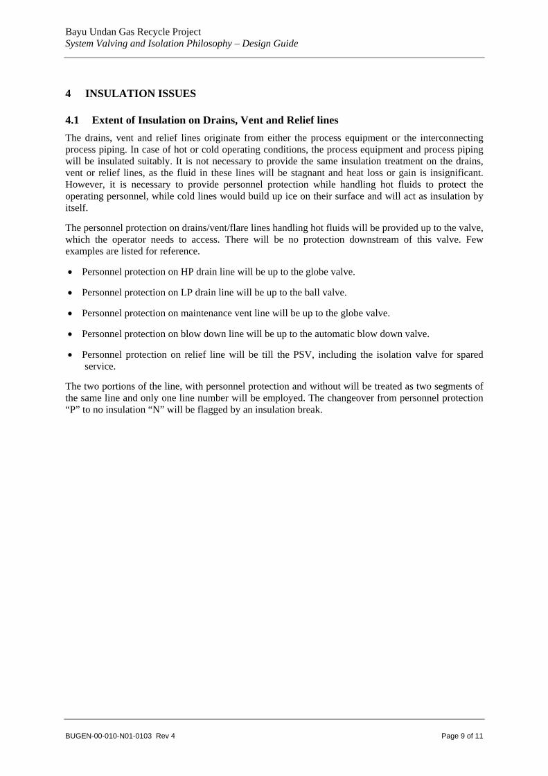
4.1 Extent of Insulation on Drains, Vent and Relief lines The drains, vent and relief lines originate from either the process equipment or the interconnecting process piping. In case of hot or cold operating conditions, the process equipment and process piping will be insulated suitably. It is not necessary to provide the same insulation treatment on the drains, vent or relief lines, as the fluid in these lines will be stagnant and heat loss or gain is insignificant. However, it is necessary to provide personnel protection while handling hot fluids to protect the operating personnel, while cold lines would build up ice on their surface and will act as insulation by itself.
The personnel protection on drains/vent/flare lines handling hot fluids will be provided up to the valve, which the operator needs to access. There will be no protection downstream of this valve. Few examples are listed for reference.
• Personnel protection on HP drain line will be up to the globe valve.
• Personnel protection on LP drain line will be up to the ball valve.
• Personnel protection on maintenance vent line will be up to the globe valve.
• Personnel protection on blow down line will be up to the automatic blow down valve.
• Personnel protection on relief line will be till the PSV, including the isolation valve for spared service.
The two portions of the line, with personnel protection and without will be treated as two segments of the same line and only one line number will be employed. The changeover from personnel protection “P” to no insulation “N” will be flagged by an insulation break.

Bayu Undan Gas Recycle Project System Valving and Isolation Philosophy – Design Guide
BUGEN-00-010-N01-0103 Rev 4 Page 10 of 11
5 TYPICAL STANDARD DETAILS Refer to Attachment A for typical standard details.

Bayu Undan Gas Recycle Project System Valving and Isolation Philosophy – Design Guide
BUGEN-00-010-N01-0103 Rev 4
ATTACHMENT A
TYPICAL STANDARDS DETAILS
(6 Pages)


Bayu Undan Gas Recycle Project System Valving and Isolation Philosophy – Design Guide
BUGEN-00-010-N01-0103 Rev 4
Vessels / PipingDrain from High Pressure Hazardous Systems
Vessels / PipingDrain from Low Pressure Hazardous Systems
NC
NC
WT Closed Drain Header
NC
High pressure carbon steel /process system metallurgy
Material spec. break
High pressure carbon steel
Low Pressure Carbon Steel
Pressure spec. break
High pressure carbon steel
NC
20
Blowdown Assembly
Low temp spec and/or highpressure spec (if applicable)
Low temp spec and/orhigh pressure spec (if
applicable)
300# (material as per highpressure spec). Low temp
spec (if applicable)
Flare Piping Spec(SS)
300# (material as per highpressure spec). Low temp
spec (if applicable)
High Pressure Spec
Min600mm
LO
Note 1
Note 2
XV RO
Expander to increaseby one line size Closed Drain Header
Expander to increaseby one line size
Note 1: Refer to Design Guide –“Reject Liquids and Solids Disposal” document No. BUGEN-00-010-N01-2000 for philosophydetails relating to Low Temperature Closed Drains. Interface with Closed Drains system engineer as required.
Note 1
Note 2, 3
Note 3
Note 2: For drainage from rotating equipment casings, the arrangement shall be a CSC block valve and normally openspectacle blind (to avoid having to swing the spec blind everytime a machine trips during startup.
Note 3: Where inadvertent opening of a single drain valve can lead to low temperatures below the limit of the drains systemmetallurgy, the drain assembly will be similar to that for high pressure equpment i.e. NC isolation valve, NC spectacle bindand NC globe valve. An example is inadvertent draining from fractionation system equipment.

Bayu Undan Gas Recycle Project System Valving and Isolation Philosophy – Design Guide
BUGEN-00-010-N01-0103 Rev 4
Single or Multiple Relief Valve Assembly (No Spare)
Flare
CSO
FB
Flare
CSO
FB
Spared Relief ValveAssembly
Flare Flare
ILO
ILO ILC
ILO
FB FB
FBFBNC NC
20
Flare
NC
FB
Note 1
Notes1. Refer to Section 3.4.3 of this document regarding pre-installation of isolation valve for possible future relief
valve in unspared relief valve assemblies.
20

Bayu Undan Gas Recycle Project System Valving and Isolation Philosophy – Design Guide
BUGEN-00-010-N01-0103 Rev 4
Notes for Blowdown and Maintenance Vent Assembly1. Use 300# spec through to downstream flare header to avoid Acoustic Induced Vibration
(AIV). It is now common practice to include excess wall thickness up to the junction withthe downstream header to eliminate AIV problems.
2. Flange set only required if upstream pipe is a different material to the flare pipe material.3. Maintenance vent assemblies for pump casings to be assessed individually (may not
require globe valve).4. In case DN25 globe valve is employed and hydrate formation conditions exist downstream
then the high pressure/low pressure spec break shall be relocated from DN25 globe valveoutlet to the enlarged pipe section downstream. A pair of flanges will be provided to allowthe higher rated section to be pressure tested.
Maintenance Vent
Low temp spec and/or highpressure spec (if applicable)
Note 2
Low temp spec and/or highpressure spec (if applicable)
300# (material as per high pressurespec). Low temp spec (if
applicable)
Min600 mm
High Pressure Spec
Note 1
300# (material as per high pressurespec). Low temp spec (if
applicable)
Flare Piping Spec (SS)
Note 4

Bayu Undan Gas Recycle Project System Valving and Isolation Philosophy – Design Guide
BUGEN-00-010-N01-0103 Rev 4
Level Instrument Isolation and Drain Assembly Hazardous Systems
To Closed Drain
From other level instruments (samevessel only)
NC
40
LT
20 NC
CSO (Note 1)
CSO (Note 1)
NC
50
50
Level Instrument Isolation and Drain Assembly Non-Hazardous Systems
To Open Drain
LT
20 NC
CSO (Note 1)
CSO (Note 1)
NC
50
50
20
20
FB
FB
Notes 1. Isolation valve to be CSO if level instrument has a safety shutdown function.

Bayu Undan Gas Recycle Project System Valving and Isolation Philosophy – Design Guide
BUGEN-00-010-N01-0103 Rev 4
Pressure Instrument and Sampling PointIsolationHazardous Systems
(integral double block and bleed assembly)
PT
CSO(Note 1)
Note 2
Pressure Instrument and Sampling Point Isolation Non-Hazardous Systems
(integral single block and bleed assembly)
PT
CSO(Note 1)
Note 2
Notes 1. Isolation valve to be CSO if pressure instrument has a safety shutdown function. 2. Size of the integral block and bleed valves will be DN20 for pressure instrument isolation and
DN40 for sampling points.
Bayu Undan Gas Recycle Project System Valving and Isolation Philosophy – Design Guide
BUGEN-00-010-N01-0103 Rev 4
RO
NC
50
NC
50
NC
50
Min 600mm
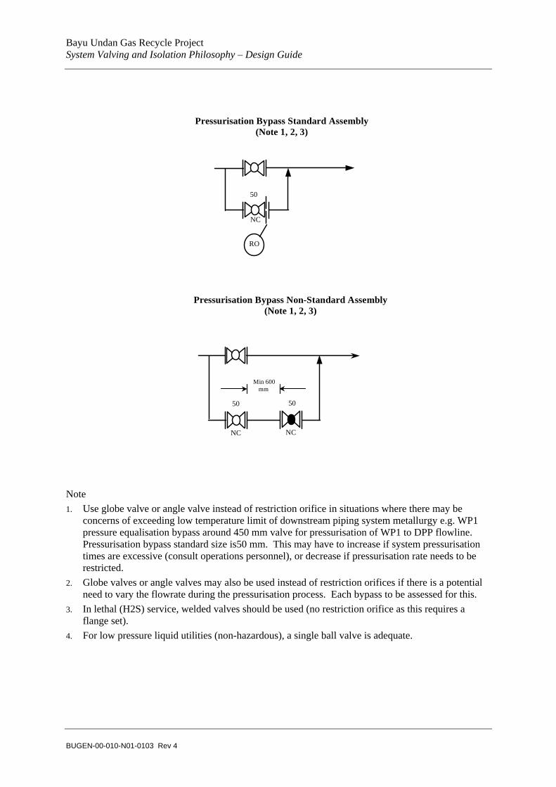
Pressurisation Bypass Standard Assembly(Note 1, 2, 3)
Pressurisation Bypass Non-Standard Assembly(Note 1, 2, 3)
Note 1. Use globe valve or angle valve instead of restriction orifice in situations where there may be
concerns of exceeding low temperature limit of downstream piping system metallurgy e.g. WP1 pressure equalisation bypass around 450 mm valve for pressurisation of WP1 to DPP flowline. Pressurisation bypass standard size is50 mm. This may have to increase if system pressurisation times are excessive (consult operations personnel), or decrease if pressurisation rate needs to be restricted.
2. Globe valves or angle valves may also be used instead of restriction orifices if there is a potential need to vary the flowrate during the pressurisation process. Each bypass to be assessed for this.
3. In lethal (H2S) service, welded valves should be used (no restriction orifice as this requires a flange set).
4. For low pressure liquid utilities (non-hazardous), a single ball valve is adequate.

Bayu Undan Gas Recycle Project System Valving and Isolation Philosophy – Design Guide
BUGEN-00-010-N01-0103 Rev 4
ATTACHMENT B
GUIDELINES FOR USE OF OPTIONS FOR POSITIVE ISOLATION
(2 Pages)

Bayu Undan Gas Recycle Project System Valving and Isolation Philosophy – Design Guide
BUGEN-00-010-N01-0103 Rev 4
1. OPTIONS FOR ACHIEVING POSITIVE ISOLATION
The following options exist for achieving positive isolation:
i) Spectacle Blind
This is a combined spacer and spade blind system used only for size/pressure combinations where weight is less than 50 kg (refer to Table 3.2 of System Valving & Isolation Philosophy).
ii) Spacer and Spade Blind
Installing a spacer with the same thickness as the fully rated spade blind. The spacer facilitates the installation of the spade blind when required (using jacking screw system).
ii) Drop Out Spools
These are normally used when:
Piping large enough to not be able to spring flange and install spade, but when a permanent spacer it’s not justified.
Insufficient flexibility to use spectacle blind / spacer and spade.
2. GUIDELINES ON USE OF OPTIONS
The attached Table indicates the preferential guidelines for application of the above options.
These guidelines are based on the following criteria / considerations:
The final selected option must be operable / maintainable.
Jacking Loads must be within practical limits of what can be applied at site.
Drop out spools must be able to be swung or lifted out ie adequate space and means of lifting to be provided.
The pre-investment in installed spectacle blinds or spacers must be justified ie. not practical to use other means.
The number of gaskets / potential leak points to be minimised.
3. P&IDs
It was agreed that Process should draft the P&ID, showing spectacle blinds or spacers in accordance with Table 3.2 in BUGEN-00-10-N01-0103, as a means of identifying the need for positive isolation.
The Piping Discipline will then consider the guidelines in the Attached Tabled, during piping layout, and determine if drop out spools are more applicable. If so the P&IDs will be modified to suit, with a standard note highlighting “drop out spool for positive isolation”.

Bayu Undan Gas Recycle Project System Valving and Isolation Philosophy – Design Guide
BUGEN-00-010-N01-0103 Rev 4
POSITIVE ISOLATION: OPTIONS AND ORDER OF PREFERENCE
Small Bore Piping Large Bore Piping
(<12 inch NB) (>12 inch NB)
1. Permanent spectacle blinds for 2” NB and smaller.
1. Permanently installed spacer (with fully rated spade blind inserted when required)
2. Drop Out Spools provided that not adding flanges and that enough flexibility / space available.
2. Drop Out Spools
(Only if detailed considerations indicate it to be better option than 1)
3. Permanently installed spectacle blinds (upto 50 kg weight max.)
4. Permanently installed spacer (with fully rated spade blind inserted when required)

Bayu Undan Gas Recycle Project System Valving and Isolation Philosophy – Design Guide
BUGEN-00-010-N01-0103 Rev 4
ATTACHMENT C
HEATING MEDIUM ISOLATION
(18 PAGES)