Embed Size (px)
Citation preview

CHAPTER 1
INTRODUCTION
BSES Rajdhani Power Limited (BRPL), a joint venture between BSES Limited and the
government of NCT of Delhi had taken over the distribution of electric power in the area
of South & West Delhi from\ Delhi Vidyut Board (DVB) on July 2002.
BSES Rajdhani Power Limited (BRPL)
BRPL distributes power to an area spread over 750 sq. km with a population density of
2192 per sq km. Its’ over 16.44 lakh customers are spread in 19 districts across South
and West areas including Alaknanda, Khanpur, Vasant Kunj, Saket, Nehru Place,
Nizamuddin, Sarita Vihar, Hauz Khas, R K Puram, Janakpuri, Najafgargh, Nangloi,
Mundka, Punjabi Bagh, Tagore Garden, Vikas Puri, Palam and Dwarka.
SN Particular Unit
BYPL
(East &
Central)
BRPL
(South &
West)
BSES
Delhi
1. Area sq. km 200 750 950
2. Customer Density Cons/sq
km 5953 2192 2984
3.Total Registered Customers (As
of Jan ’11) Lacs 11.90 16.44 28.34
4. Peak Demand (FY 2010-11) MW 1180 1920 3100
5.Consumption per year (FY 2010-
11) Mus 5227 9177 14404
SN ITEMS2010 - 11 (DECEMBER)
BRPL BYPL BSES
1. No. of Grids 72 49 121
2. No. of Power Transformers 197 135 332
3. EHV Capacity (MVA) 4393 2789 7182
4. EHV Cable Laid (KM) 1077 770 1847
5. No. of 66 & 33 KV Feeders 177 132 309
6 Shunt Capacitors (MVAr) 1399 910 2309
7. No. of Distribution Transformer 6701 3249 9950
8. Distribution Transformer Capacity (MVA) 4049 2304 6353
9. No. of 11 KV Feeders 1025 680 1705
10. 11 KV Cables laid (kms) 2059 1748 3807
11. 11 KV Lines laid (kms) 1714 251 1965
12. Total No. of LT Feeders 21587 13268 34855
Road Map to Privatisation
Through out this process, government’s primary goal was improving the performance of
Delhi Vidyut Board (DVB), by privatizing the distribution system, which would be the
key to successful reforms in this sector. DVB has been unbundled into six companies: -
1 One holding company
2 One generation company (GENCO),
3 One transmission company (TRANSCO) and
4 Three distribution companies (DISCOMS)
REL has acquired a controlling interest in two of the distribution companies, viz. BRPL
& BYPL and NDPL has taken over the management of third distribution company viz.
northwest Delhi distribution company Limited. DVB distribution area (1397 sq. km.)
divided into six circles (Central, North, West, East, South, North west). NDMC (43 sq.
km.) and MES (43 sq. km.) cater to government areas and cantonment areas. The two
distribution companies, BRPL covering south & west areas & BYPL covering east and
central regions provide electricity to around 17
lac consumers spread across an area of 900 square km (approx).
DIVISIONS OF BSES
Business Department: It takes care of the billing mechanism.
Graphical Interface Service: It is a system to tell about the location of grids,
substations, feeder pillars etc.
Supervisory Control Data Acquisition (SCADA): This system helps us to control a
grid or substation from a distant place by using different sensors for current,
voltage ,temperature etc. (unit collectively is called Remote Terminal Unit or RTU) and
these sensors send information to a distant place from where the station is to be
controlled with the help of radio waves and then we give commands which control the
relays of circuit breakers present at the substation.
Operation and Maintenance (O & M): It consists of five subdivisions which have been
discussed below.
Finance Department: It provides the necessary amount of money for the execution of
new schemes and maintenance of the already installed equipments.
Quality Control and Network Securitization: It checks the quality of the newly
executed schemes and also check already installed equipments’ quality. It has also the
responsibility of the security of the whole network of BSES in an area.
Enforcement: It keeps an eye on the illegal processes and thefts occurring either
externally or internally. External means theft by the public and internal theft refers to the
illegal acts done by the employees of B.S.E.S.
Construction and Management Department: This department plans for the
development of the present system keeping in view the load demand in future and also
executes it.
Human Resources Department: It does the recruitment of the employees and selects
them to work in BSES.
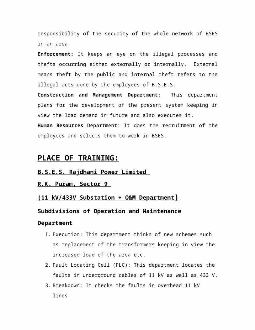
PLACE OF TRAINING:
B.S.E.S. Rajdhani Power Limited
R.K. Puram, Sector 9
(11 kV/433V Substation + O&M Department )
Subdivisions of Operation and Maintenance Department
1. Execution: This department thinks of new schemes such as replacement of the
transformers keeping in view the increased load of the area etc.
2. Fault Locating Cell (FLC): This department locates the faults in underground
cables of 11 kV as well as 433 V.
3. Breakdown: It checks the faults in overhead 11 kV lines.
4. Zone: No Current Complaints from the consumers’ side are taken care of by this
department.
Zone also does the work of Preventive and Maintenance. In order to avoid any major
fault during summer’s peak load demand, Zone has to carry out some tests and
maintenance work on the feeders and substation equipments in the time span of four
months during winter season.
FEEDERS: all feeders are checked and if any damaged part is found then it is
changed.
TRANSFORMER: there are done 3 tests on transformer a) earth testing b) megger
insulation test c) BDV test of oil.
CHAPTER -2
SUBSTATIONS FOR DISTRIBUTION:
These are the step down substations which transform 11 kV voltage to 433 V.
Substations for distribution are 1)package type 2)pole mounted 3)indoor type
4)plinth mounted
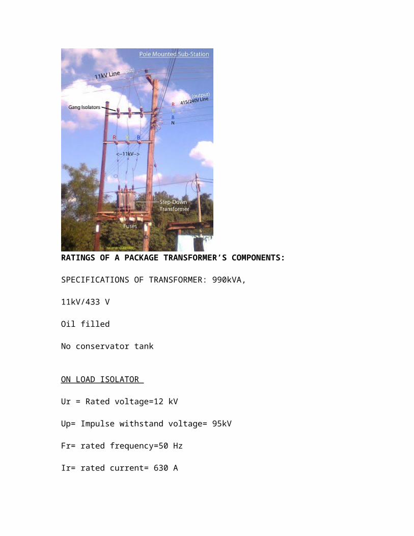
POLE MOUNTED SUBSTATION;These substations are erected for mounting distribution transformers of capacity upto 250
kVA. HT fuse unit is used for protection of HT side. To control LT side iron clad low
tension switch for suitable capacity with fuses is installed. Lightning arresters are
installed over the ht line to protect transformer from surges. Substation is earthed at two
or more places. Generally transformers of capacity upto 125 kVA but not exceeding 250
kVA, 4-pole structure with suitable platform is used. This type of pole mounted
substation is erected in very thickly populated location.
The maintenance cost of such substations is low and by using a large number of such
substations in a town it is possible to lay the distributors, at lower cost.
But disadvantage is that due to increase in number of transformers, losses are more.
RATINGS OF A PACKAGE TRANSFORMER’S COMPONENTS:
SPECIFICATIONS OF TRANSFORMER: 990kVA, 11kV/433 V Oil filled No conservator tank
ON LOAD ISOLATOR
Ur = Rated voltage=12 kV
Up= Impulse withstand voltage= 95kV
Fr= rated frequency=50 Hz
Ir= rated current= 630 A
Ik= short time current rating= 21 kA
tk= short time rating= 3 seconds
CIRCUIT BREAKER (SF6 type)Ur = Rated voltage=12 kV
Up= Impulse withstand voltage= 95kV
Fr= rated frequency=50 Hz
Ir= rated current= 200 A
Ik= short time current rating= 21 kA
tk= short time rating= 3 seconds
TC= temperature range= -25 to 40 degree Celsius (without adding ambient temperature)
Rated Pressure of SF6 gas= 1.4 X 10^5 Pa
Substation is mainly made up of three important parts a) HT Panel b) Distribution
Transformer c) LT Panel
HT PANEL: It is the part through which the 11 kV supply is fed to the transformer. The
HT Panel has circuit breakers either oil circuit breakers or SF6 circuit breakers, isolators
and earth switch.
DISTRIBUTION TRANSFORMER
transformer which is used for the purpose of distribution of power.
11kv/433v is the standard voltage rating.
standard kva ratings are
25,63,100,160,200,250,315,400,500,630,750,1000,1250,1500,2000,2500 kva.
is-2026 is the national i s standard.
main features
mineral oil (IS 335) filled transformer , 3 phase,50Hz
primary is delta connected and secondary is star connected.
naturally cooled (onan type).
amongst all the types of transformers this is the most required and most used type.
ACCESSORIES OF TRANSFORMER
1. Oil temperature Indicator: It tells the temperature of the oil. This meter has two needles
one red and one black. Black shows the present temperature of the oil and red one shows
the maximum temperature reached because it stops at the maximum temperature of oil
always.

2. Winding temperature indicator: It shows the temperature of the main winding of the
transformer.
3. Breather: When transformer becomes warm the oil and gas expand. The gas at the top
of oil is expelled out. When transformer cools, the air is drawn into the oil tank and
moisture is drawn during this process called breathing due to which dielectric properties
of oil is reduced. The air can be made moisture free by letting it pass through an
apparatus called breather which contains a vent pipe and dehydrating material such a
silica gel which becomes blue when it is dry and pink when damp.
4. Conservator tank: when transformer suffers short circuit problem and temperature rises
excessively, the vaporization of large part of oil takes place. The oil vapours form
explosive mixture with air that ignites and may cause a considerable damage. For this
reason. A conservator tank is provided so that the oil level may be kept some distance
below the top cover to provide space for oil expansion under temperature rise. In this
context diaphragm and air cell are also used along with the conservator.
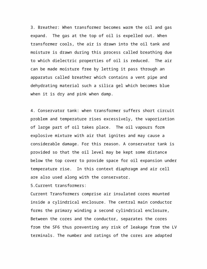
5.Current transformers:
Current Transformers comprise air insulated cores mounted inside a cylindrical
enclosure. The central main conductor forms the primary winding a second cylindrical
enclosure, Between the cores and the conductor, separates the cores from the SF6 thus
preventing any risk of leakage from the LV terminals. The number and ratings of the
cores are adapted according to customer requirements. Current Transformers can be
installed on either or both sides of the circuit-breakers and at the ends of outgoing
circuits.

Current Transformer (Make Alstom)
1 - Gas tight enclosure
2 - Terminal box
3 - Secondary windingwww.sayedsaad.com
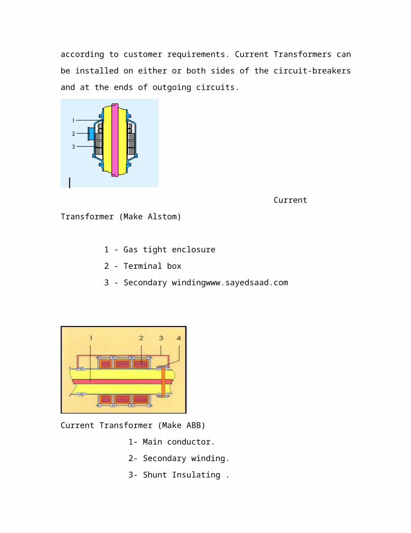
Current Transformer (Make ABB)
1- Main conductor.
2- Secondary winding.
3- Shunt Insulating .
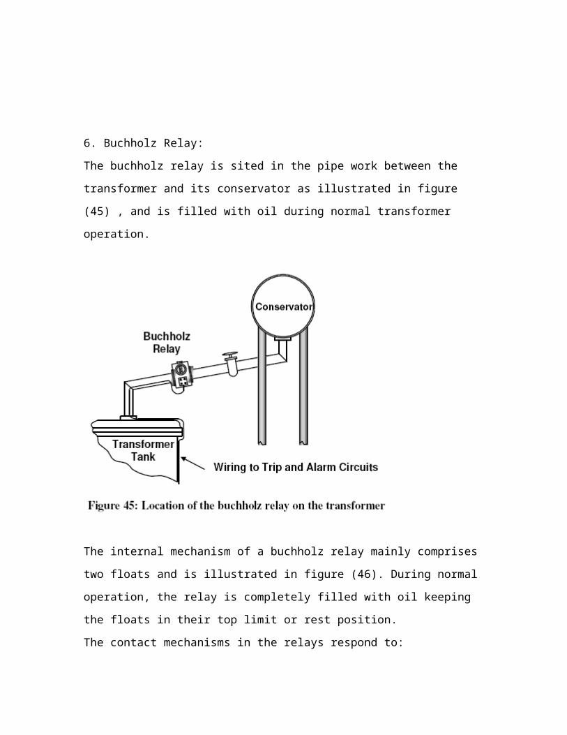
6. Buchholz Relay:
The buchholz relay is sited in the pipe work between the transformer and its conservator
as illustrated in figure (45) , and is filled with oil during normal transformer operation.

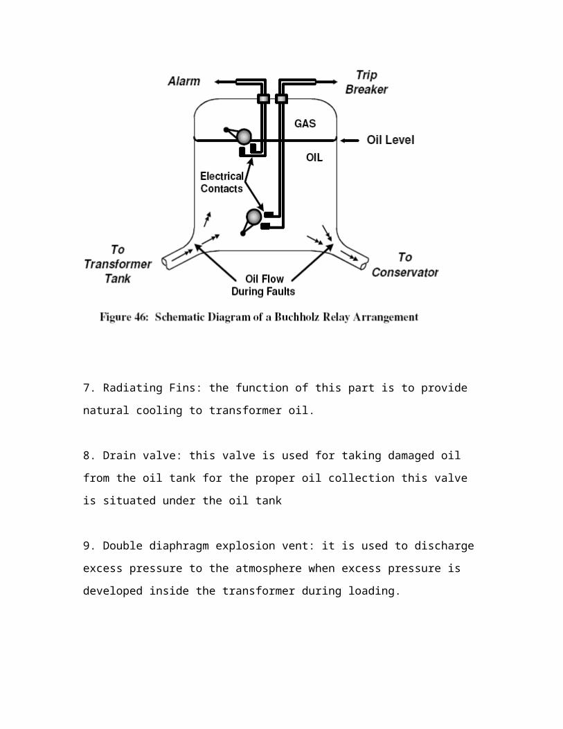
The internal mechanism of a buchholz relay mainly comprises two floats and is
illustrated in figure (46). During normal operation, the relay is completely filled with oil
keeping the floats in their top limit or rest position.
The contact mechanisms in the relays respond to:
1. Slight faults causing a slow evolution of gas in the transformer (e.g. overheating)
2. Serious faults creating an immediate surge of oil (e.g. short circuits etc.)
3. Oil leakage
Buchholz Relay Operation
When a slight fault occurs in the transformer, the small bubbles of gas which pass
upwards towards the oil conservator tank are trapped in the relay housing this causing its
oil level to fall. As a result, the upper float drops and activates the external alarm switch.
If gas continues to be generated then the second float operates the second switch that is
normally used to isolate (trip) the transformer.
7. Radiating Fins: the function of this part is to provide natural cooling to transformer oil.
8. Drain valve: this valve is used for taking damaged oil from the oil tank for the proper
oil collection this valve is situated under the oil tank
9. Double diaphragm explosion vent: it is used to discharge excess pressure to the
atmosphere when excess pressure is developed inside the transformer during loading.
10. Oil level scale: it is used to show the oil level in the main tank.
11. Bushings: These are made up of porcelain body. The bushing acts as an insulator to
prevent a short circuit. In large distribution transformers, the voltages used are so high
that it the wires cannot be allowed to come too close to each other, or too close to the
metal casing of the transformer. If they do get too close, then the voltage can actually
jump through the air (electrical breakdown), and create a short circuit. The bushings are
made longer than they need to be because things like rain, and sharp points on a
transformer terminal can make it easier for the voltage to jump through the air.
12. Tap changer: tapping is done on the HV side generally as the current flowing on this
side is less hence tap changing is easier. Whenever there is a problem of low voltages in
homes etc. the voltage is increased. There are 5 different taps for five different HT side
voltages.
13. Cleats: they are made up of wood and prevent the extra strain on the bushings.
TYPES OF COOLING SYSTEMS IN TRANSFORMERS:
Oil Immersed Natural Cooled (ONAN): Here, both the core and the windings are kept
immersed in oil. The transformer is cooled by the natural circulation of this oil.
Additional cooling can be provided by radiators, which increase the surface area over
which a large transformer can dissipate heat.
Oil Immersed Air Blast (ONAF): In this case air is circulated and the transformer
cooled with the help of fans. Fans allow one to have a smaller transformer for a
given rating, since not as much surface area is needed for heat dissipation. This in
turn can cut costs.
Oil Immersed Water Cooled (ONWN): Here the transformer is cooled by an
internal coil through which water flows. This method is feasible so long as there
is a readily available source of a substantial amount of water, which is not always
the case. This kind of cooling has become less common in recent years,
abandoned in favor of Forced Oil Water Cooled (OFWF).
Forced Oil Air Blast Cooled (OFAF): In this case, cooling is accomplished in two
ways. Oil circulation is facilitated by a pump, and fans are added to the radiators
to provide blasts of air.
Forced Oil Natural Air Cooled (OFAN): For this type of cooling, a pump is
included within the oil circuit to aid in oil circulation.
Forced Oil Water Cooled (OFWF): Here, a pump within the oil circuit forces the
oil to circulate out through a separate heat exchanger in which water flows.
The most dependable type of cooling system for a transformer is the oil-immersed
naturally cooled (ONAN), which also produces the least noise. A forced-air cooled
transformer (OFAF) is more efficient, but it is also noisier and less reliable on
account of the possibility of fan malfunction.
The method of forced cooling has been used for many years now to increase the loading
capacities of transformers. A transformer's thermal performance can be directly improved
by the implementation of cooling systems. Consequently, it makes sense to avoid excess
heating and accelerated aging within a transformer by using the appropriate cooling
system.
IMPORTANCE AND MAINTENANCE OF COOLING SYSTEMS
The load that a transformer carries without heat damage can be increased by using an
adequate cooling system. This is due to the fact that a transformer's loading capacity is
partly decided by its ability to dissipate heat. If the winding hot spot temperature reaches
critical levels, the excess heat can cause the transformer to fail prematurely by
accelerating the aging process of the transformer's insulation. A cooling system increases
the load capacity of a transformer by improving its ability to dissipate the heat generated
by electric current. In other words, good cooling systems allow a transformer to carry
more of a load than it otherwise could without reaching critical hot spot temperatures.
One of the more common types of transformer cooling equipment is auxiliary fans. These
can be used to keep the radiator tubes cool, thereby increasing the transformer's
ratings. Fans should not be used constantly, but rather only when temperatures are such
that extra cooling is needed. Automatic controls can be set up so that fans are turned on
when the transformer's oil or winding temperature grows too high.
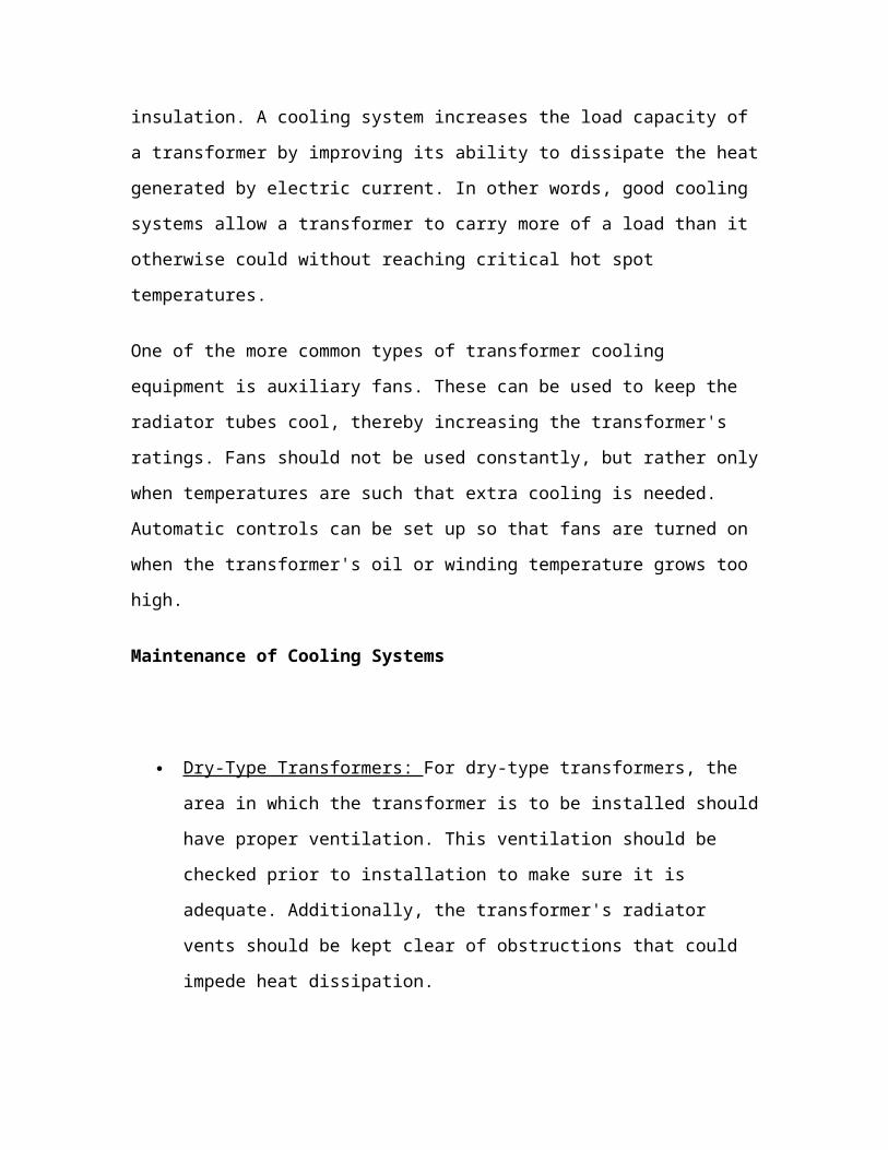
Maintenance of Cooling Systems

Dry-Type Transformers: For dry-type transformers, the area in which the
transformer is to be installed should have proper ventilation. This ventilation
should be checked prior to installation to make sure it is adequate. Additionally,
the transformer's radiator vents should be kept clear of obstructions that could
impede heat dissipation.
Forced Air: If the transformer's temperature is being kept at acceptable levels by
forced air from a fan, the fan's motors should be checked periodically to make
sure they are properly lubricated and operate well. The thermostat that ensures the
motors are activated within the preset temperature ranges should be tested as well.
Water cooled systems: Systems that are cooled by water should be tested
periodically to make sure they operate properly and do not leak. Leaks can be
checked by raising the pressure within the cooling system, which can be done in
various ways. If the cooling coils can be removed from the transformer, internal
pressure can be applied by adding water. Otherwise, pressure checks can also be
made using air or coolant oil, if the coils need to be checked within the
transformer itself.
If the cooling coils are taken out of the transformer, the water cooling system as a
whole can be tested. Here, the coils are filled up with water until the pressure
reaches 80 to 100 psi, and left under that pressure for at least an hour. Any drop
in pressure could be a sign of a leak. The other equipment linked to a water-
cooled system can be tested at the same time, such as the alarm system, water
pump and pressure gauges. Also, the water source should be tested to make sure it
has sufficient flow and pressure.
Liquid coolants: When oil coolants are prepared they are dehydrated, and
processed to be free of acids, alkalis, and sulfur. They should also have a low
viscosity if they are to circulate easily. If a transformer is cooled by oil, the
dielectric strength of the oil should always be tested before the transformer is put
into service.
LT PANEL: It is made up of LT main and Air Circuit breakers. LT main receives three
phases and normal from the transformer output from where these phases are given to
different air circuit breakers.
Transformer rating :400 kVA (Marsons Electrical Ltd.)HV 11000 VLV 433VHV current rating 21 ALV current rating 533 AVector group Dyn11Type of cooling ONANMass of oil 380 kg (425 litre)Total mass 1650 kgNo load loss 800 wattsLoad loss 4841 wattsMax rise allowed in temperature 45˚C (50˚C ambient temperature excluded
Transformer rating :630 kVA (PM Electronic, Surajpur U.P.)
HV 11000 VLV 433VHV current rating 33 ALV current rating 840 AVector group Dyn11Type of cooling ONANMass of oil 465 kgTotal mass 2065 kgPercentage impedance 5%No load loss 1200 watts

Load loss 7500 wattsMax rise allowed in temperature 45˚C (50˚C ambient temperature excluded)
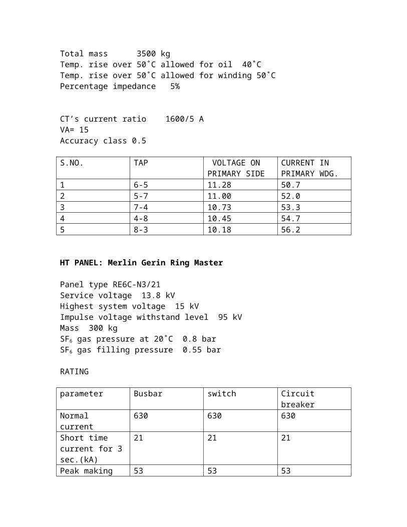
Transformer rating :990 kVA (alstom) HV 11000 VLV 433VHV current rating 52 ALV current rating 1320 AVector group Dyn11Type of cooling ONANMass of oil 580 kgMass of tank and fitting 1240 kgMass of core and coil 1680 kgTotal mass 3500 kgTemp. rise over 50˚C allowed for oil 40˚CTemp. rise over 50˚C allowed for winding 50˚CPercentage impedance 5%
CT’s current ratio 1600/5 AVA= 15Accuracy class 0.5
S.NO. TAP VOLTAGE ON PRIMARY SIDE
CURRENT IN PRIMARY WDG.
1 6-5 11.28 50.72 5-7 11.00 52.03 7-4 10.73 53.34 4-8 10.45 54.75 8-3 10.18 56.2
HT PANEL: Merlin Gerin Ring Master
Panel type RE6C-N3/21Service voltage 13.8 kVHighest system voltage 15 kVImpulse voltage withstand level 95 kVMass 300 kgSF6 gas pressure at 20˚C 0.8 barSF6 gas filling pressure 0.55 bar
RATING
parameter Busbar switch Circuit breaker

Normal current 630 630 630Short time current for 3 sec.(kA)
21 21 21
Peak making current (kA)
53 53 53
Makes of Transformers being used in BSES Rajdhani Power Limited
1.) 990/1000 kVAa.)Alstomb.)KANOHAR Electrical Ltd. c.)KOTSONS Pvt. Ltd.d.)Marsons Electrical Industriese.)KIRLOSKAR Power Equipments, Pune.f.)Crompton Greaves
2.) 630 kVAa.) PM Electronics (U.P.)b.) KOTSONS Pvt. Ltd.c.) Jaybee Industries (Bhatinda)d.) Mirzapur Electrical Industriese.) Electric Construction and Equipment Co. Ltd.f.) Eastern Transformer & Equipment Ltd.g.) NGEFh.) Marsons Electrical Industriesi.) Crompton Greaves
3.) 400 kVAa.) Marsons Electrical Industriesb.) NGEFc.) Paramax Electonics Pvt. Ltd.d.) Electronic Construction and Equipment Ltd.e.) Associated Electrical Gzb Pvt. Ltd.f.) KANOHAR Electrical Ltd. g.) Capital Transformers (Jhilmil) Shahdra

Makes of HT panels in BRPL
a.) Merlin Gerin Ring Masterb.) Merlin Gerinc.) ABB Saferingd.) AREVAe.) HT Switches (Germany)f.) SAAME/NINGBO TIANAN Group Co Ltdg.) Southern Switchgear Ltd.h.) Siemensi.) ECE West Bengal j.) Reyroll Bum
Makes of LT panels in BRPL
a.) ABB MCCB switchesb.) C & Sc.) Crompton Greavesd.) Jyoti Ltd. Vadodarae.) GE Indiaf.) Merlin Gerin
CAPACITOR BANK DETAILS
1.) RMS Automation System Pvt Ltd.
Model 1. RMS Varcap LV 415 V, 3 phase 300 kVAR maximum (10 kVAR- 30 Banks) Load 1000 kVA Model 2. RMS Varcap LV 415 V, 3 phase 200 kVAR maximum (10 kVAR- 20 Banks)
2.) Saha Spragul Ltd (Mumbai)
Model 1. Autovark 200 Current 262 A
Steps 12 200 kVAR
Model 2. Autovark 300 Current 394 A Steps 12 X 25 300 kVAR
CHAPTER 3
CIRCUIT BREAKERS
The Circuit Breakers are automatic Switches which can interrupt fault
currents. The part of the Circuit Breakers connected in one phase is called the
pole. A Circuit Breaker suitable for three phase system is called a ‘triple-pole
Circuit Breaker. Each pole of the Circuit Breaker comprises one or more
interrupter or arc-extinguishing chambers. The interrupters are mounted on
support insulators. The interrupter encloses a set of fixed and moving contact's

The moving contacts can be drawn apart by means of the operating links
of the operating mechanism. The operating mechanism of the Circuit Breaker
gives the necessary energy for opening and closing of contacts of the Circuit
Breakers.
The arc produced by the separation of current carrying contacts is interrupted
by a suitable medium and by adopting suitable techniques for arc extinction.
The Circuit Breaker can be classified on the basis of the arc extinction
medium.
A circuit breaker is required to perform the following three duties:
1. It must be capable of opening the faulty circuit and breaking the fault current.
2. It must be capable of being closed on to a fault
3. Must be capable of carrying fault current for a short time while another breaker is clearing the fault.
Depending on the above duties circuit breaker has three ratings braking capacity, making
capacity and short time capacity.
THE FAULT CLEARING PROCESS
During the normal operating condition the Circuit Breaker can be opened or
closed by a station operator for the purpose of Switching and maintenance.
During the abnormal or faulty conditions the relays sense the fault and close
the trip circuit of the Circuit Breaker. Thereafter the Circuit Breaker opens.
The Circuit Breaker has two working positions, open and closed.
These correspond to open Circuit Breaker contacts and closed Circuit Breaker
contacts respectively. The operation of automatic opening and closing the
contacts is achieved by means
of the operating mechanism of the Circuit Breaker. As the relay contacts
close, the trip circuit is closed and the operating mechanism of the Circuit
Breaker starts the opening operation. The contacts of the Circuit Breaker

open and an arc is draw between them. The arc is extinguished at some natural
current zero of a.c. wave. The process of current interruption is completed
when the arc is extinguished and the current reaches final zero value. The fault
is said to be cleared.
SEQUENCE OF FAULT CLEARING
1.) Fault Occurs. As the fault occurs, the fault impedance being low,
the currents increase and the relay gets actuated.
The moving part of the relay move because of the increase in the operating
torque. The relay takes some time to close its contacts.
2.) Relay contacts close the trip circuit of the Circuit Breaker closes and trip coil is
energized.
3.) The operating mechanism starts operating for the opening operation.
The Circuit Breaker contacts separate.
4.) Arc is drawn between the breaker contacts. The arc is extinguished
in the Circuit Breaker by suitable techniques. The current reaches final zero
as the arc is extinguished and does not restrict again.
The Trip-Circuit
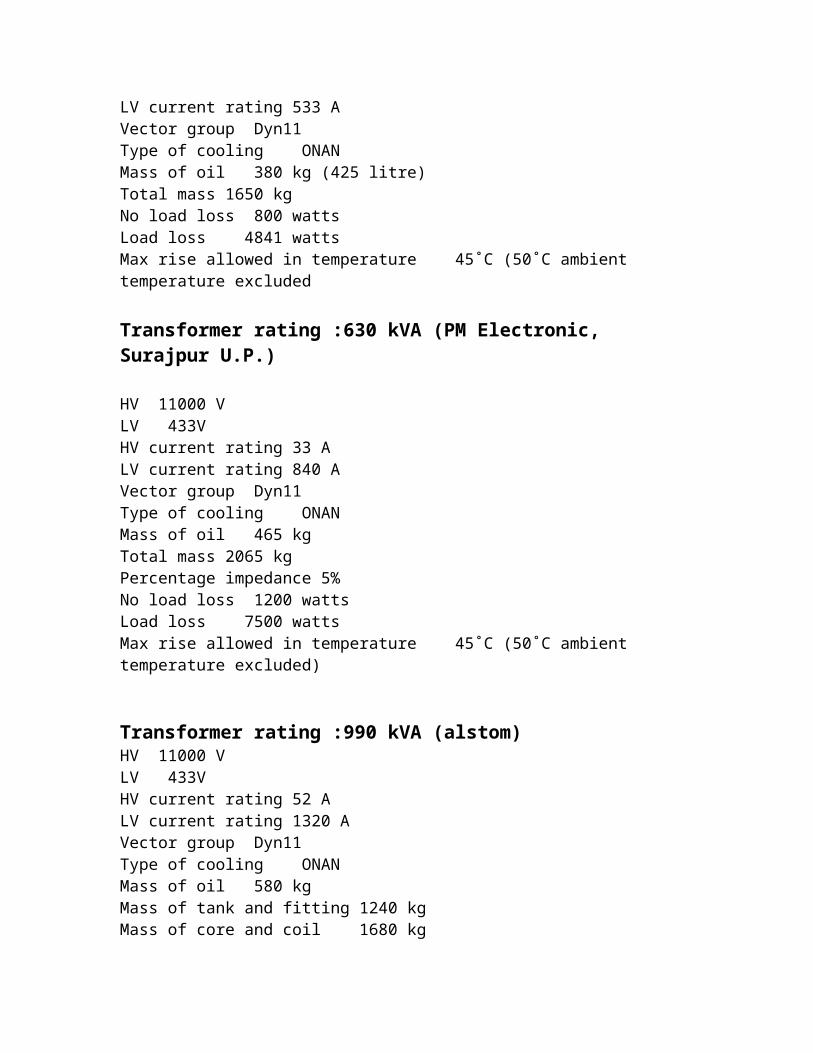
Fig (1) the basic connections of the Circuit Breaker control for the opening
operation
The type of the Circuit Breaker
The type of the Circuit Breaker is usually identified according to the medium of arc extinction
(1) Air break' Circuit Breaker
(2) Oil Circuit Breaker (tank type of bulk oil)
(3) Minimum oil Circuit Breaker.
(4) Air blast Circuit Breaker.
(5) Vacuum Circuit Breaker.
(6) Sulphur hexafluoride Circuit Breaker. (Single or Double Pressure).
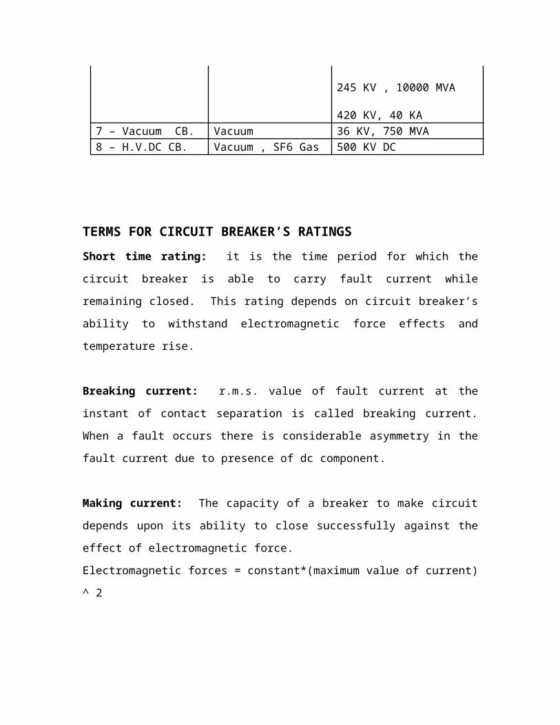
Type Medium Voltage, Breaking Capacity
1 – Air break Circuit Breaker
Air at atmospheric pressure
(430 – 600) V– (5-15)MVA(3.6-12) KV - 500 MVA
2 – Miniature CB. Air at atmospheric pressure
(430-600 ) V
3 – Tank Type oil CB. Dielectric oil (3.6 – 12) KV4 – Minimum Oil CB. Dielectric oil (3.6 - 145 )KV5 – Air Blast CB. Compressed Air
(20 – 40 ) bar245 KV, 35000 MVAup to 1100 KV, 50000 MVA
6 – SF6 CB. SF6 Gas 12 KV, 1000 MVA
36 KV , 2000 MVA
145 KV, 7500 MVA
245 KV , 10000 MVA
420 KV, 40 KA7 – Vacuum CB. Vacuum 36 KV, 750 MVA 8 – H.V.DC CB. Vacuum , SF6 Gas 500 KV DC
TERMS FOR CIRCUIT BREAKER’S RATINGS
Short time rating: it is the time period for which the circuit breaker is able to carry fault
current while remaining closed. This rating depends on circuit breaker’s ability to
withstand electromagnetic force effects and temperature rise.
Breaking current: r.m.s. value of fault current at the instant of contact separation is
called breaking current. When a fault occurs there is considerable asymmetry in the fault
current due to presence of dc component.
Making current: The capacity of a breaker to make circuit depends upon its ability to
close successfully against the effect of electromagnetic force.
Electromagnetic forces = constant*(maximum value of current) ^ 2
The peak value of current during the first cycle of current wave after closure of the circuit
breaker is known a making current.

ARC CHUTES IN CIRCUIT BREAKERS
Basically an old or new circuit breaker arc chute stretches the arcing that takes place
when a circuit breaker opens, such that the arc is too long for the voltage to keep it going.
Arc chutes have arc dividers in the form of flat segments stacked one above the other,
with an air gap between them. When the arc occurs, it is expelled into the arc chute and
into the arc dividers, such that it wraps back and further between the arc dividers. The
wrapping back and forth around the arc dividers effectively stretches the length of the arc
until it is just too long for the voltage to keep it going. When this happens, the arcing
stops. The arc has been extinguished. When the circuit breaker opens, the main current
carrying contacts open first and a different set of contacts, the arcing contacts, open
second, such that the arcing contacts endure limited damage from the arcing, until the arc
chutes interrupt the arc. So the combination of the arc chutes and the arcing contacts
protect the main contacts from arcing damage when the circuit breaker opens and when it
closes. When a circuit breaker is closed, the arcing contacts close first, again taking on
the arc such that the main contacts are protected from arcing damage when closed. This
is especially important when the circuit breaker interrupts a high current fault and there is
a real blast in the arc chutes. Each phase, i.e. pole, of a circuit breaker has a separate arc
chute. This is pretty much how the arc chutes of obsolete, old, and new replacement
circuit breakers operate. So the arc chutes perform an extremely important function.
REASON FOR SPRING CHARGING BEFORE SWITCHING ON THE CIRCUIT
BREAKER
To switch on a circuit breaker, we need to charge the spring first mechanically.
Reason: as we begin to close the electrical contacts the gap between the contacts goes on
decreasing and hence the dielectric strength of the air does. If we do the act of making
the contacts slowly the n it will heat up the surface material of the contact too much,
make it melt and vaporize.
This mechanically charged does the closing and even opening (during tripping) of the
contacts at a predetermined speed according to the current that the device is supposed to
carry.

In addition as current goes up the electromagnetic forces caused by the current will
increase and try to force the contacts apart. We therefore need a strong mechanical force
keeping them together. Charged spring provides that force too.
AIR BREAK CIRCUIT BREAKER
These circuit breakers employ high resistance interruption principle. The arc is rapidly
lengthened by means of the arc runners and arc chutes and the resistance of the arc is
increased by cooling, lengthening and splitting the arc. The arc resistance increases to
such an extent that the voltage drop across the arc becomes more than the supply voltage
and the arc extinguished.
Air breaker circuit breakers are used in d.c circuits and a.c circuits upto 12 kV.
Magnetic field is utilized for lengthening the arc in high voltage air break circuit breaker.
The arc resistance is increased to such an extent that the system voltage cannot maintain
the arc and the arc gets extinguished.
There are two set of contacts: Main contacts (1) and Arching contacts (2).
Main contacts conduct the current in closed position of the breaker. They have low
contact resistance and are silver plated. The arching contacts (2) are hard, heat resistance
and usually made of copper alloy. While opening the contact, the main contacts dislodge
first. The current is shifted to the arching contacts. The arching contacts dislodge later
and arc is drawn between them (3). This arc is forced upwards by the electromagnetic
force and thermal action. The arc ends travel along the Arc Runner (Arcing horns). The
arc moves upwards and is split by arc splitter plates (5). The arc is extinguished by
lengthening, cooling, splitting etc. In some breakers the arc is drawn in the direction of
the splitter by magnetic field.

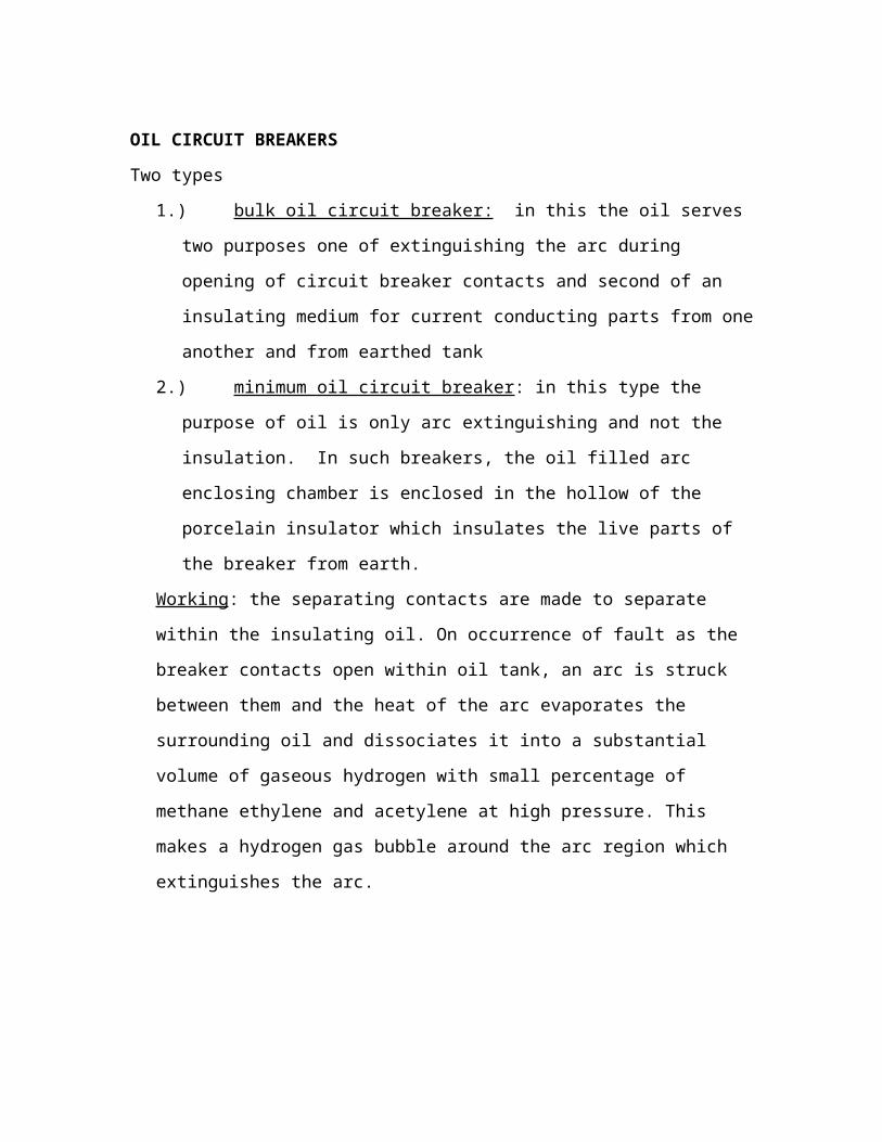
OIL CIRCUIT BREAKERS
Two types
1.) bulk oil circuit breaker: in this the oil serves two purposes one of extinguishing
the arc during opening of circuit breaker contacts and second of an insulating
medium for current conducting parts from one another and from earthed tank
2.) minimum oil circuit breaker : in this type the purpose of oil is only arc
extinguishing and not the insulation. In such breakers, the oil filled arc enclosing
chamber is enclosed in the hollow of the porcelain insulator which insulates the
live parts of the breaker from earth.
Working: the separating contacts are made to separate within the insulating oil. On
occurrence of fault as the breaker contacts open within oil tank, an arc is struck
between them and the heat of the arc evaporates the surrounding oil and dissociates it
into a substantial volume of gaseous hydrogen with small percentage of methane
ethylene and acetylene at high pressure. This makes a hydrogen gas bubble around
the arc region which extinguishes the arc.
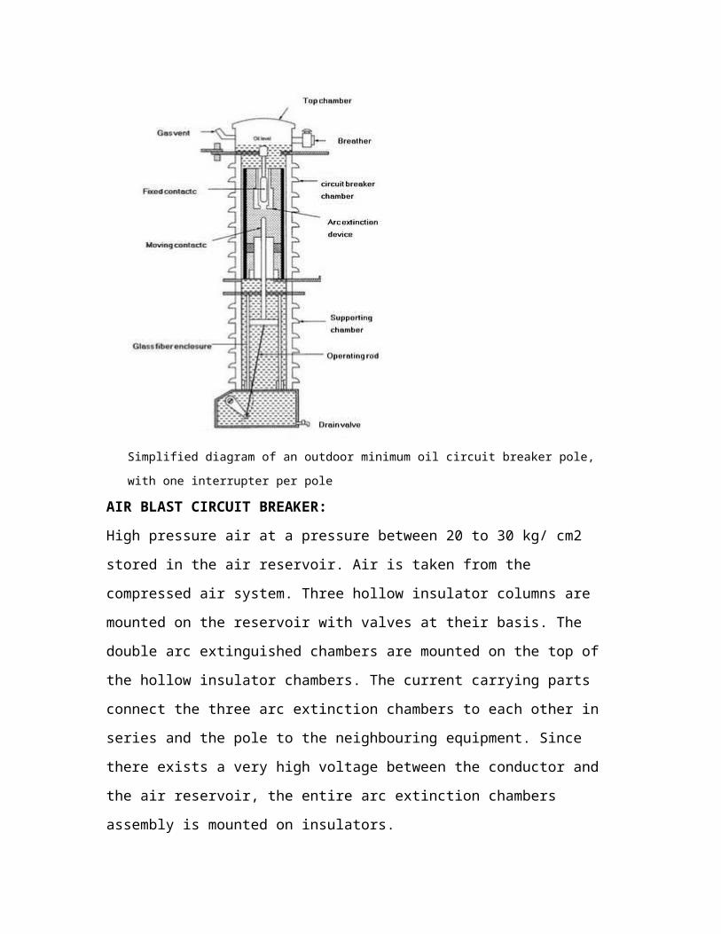
Simplified diagram of an outdoor minimum oil circuit breaker pole, with one interrupter per pole

AIR BLAST CIRCUIT BREAKER:
High pressure air at a pressure between 20 to 30 kg/ cm2 stored in the air reservoir. Air is
taken from the compressed air system. Three hollow insulator columns are mounted on
the reservoir with valves at their basis. The double arc extinguished chambers are
mounted on the top of the hollow insulator chambers. The current carrying parts connect
the three arc extinction chambers to each other in series and the pole to the neighbouring
equipment. Since there exists a very high voltage between the conductor and the air
reservoir, the entire arc extinction chambers assembly is mounted on insulators.
i)Axial-blast type in which air-blast is directed along the arc path as shown in figure
below.
(ii) Cross-blast type in which air blast is directed at right angles to the arc path as shown in figure below

(iii) Radial-blast type in which the air blast is directed radially as shown in figure below
(i) Axial-blast air circuit breaker
The figure below shows the essential components of a typical axial blast circuit breaker. The fixed and moving contacts are held in closed position by spring pressure under normal conditions. The air reservoir is connected to the arcing chamber through an air valve. This valve remains closed under normal conditions but opens automatically by tripping impulse when a fault occurs on the system.
When a fault occurs, the tripping impulse causes the opening of the air valve which connects the circuit breaker reservoir to the arcing chamber. The high pressure air entering the arcing chamber pushes away the moving contact against spring pressure. The moving contact is separated and an arc is struck. At the same time, high pressure air blast flows along the arc and takes away the ionised gases along with it. Consequently the arc is extinguished and current flow is interrupted.
It may be noted that in such circuit breakers, the contact separation required for interruption is generally small about 1.75 cm. Such a small gap may constitute inadequate clearance for the normal service voltage. Therefore, an isolating switch is incorporated as part of this type of circuit breaker. This switch opens immediately after fault interruption to provide necessary clearance for insulation.

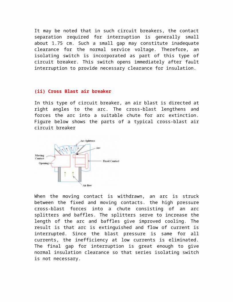
(ii) Cross Blast air breaker
In this type of circuit breaker, an air blast is directed at right angles to the arc. The cross-blast lengthens and forces the arc into a suitable chute for arc extinction. Figure below shows the parts of a typical cross-blast air circuit breaker
When the moving contact is withdrawn, an arc is struck between the fixed and moving contacts. the high pressure cross-blast forces into a chute consisting of an arc splitters and baffles. The splitters serve to increase the length of the arc and baffles give improved cooling. The result is that arc is extinguished and flow of current is interrupted. Since the blast pressure is same for all currents, the inefficiency at low currents is eliminated. The final gap for interruption is great enough to give normal insulation clearance so that series isolating switch is not necessary.
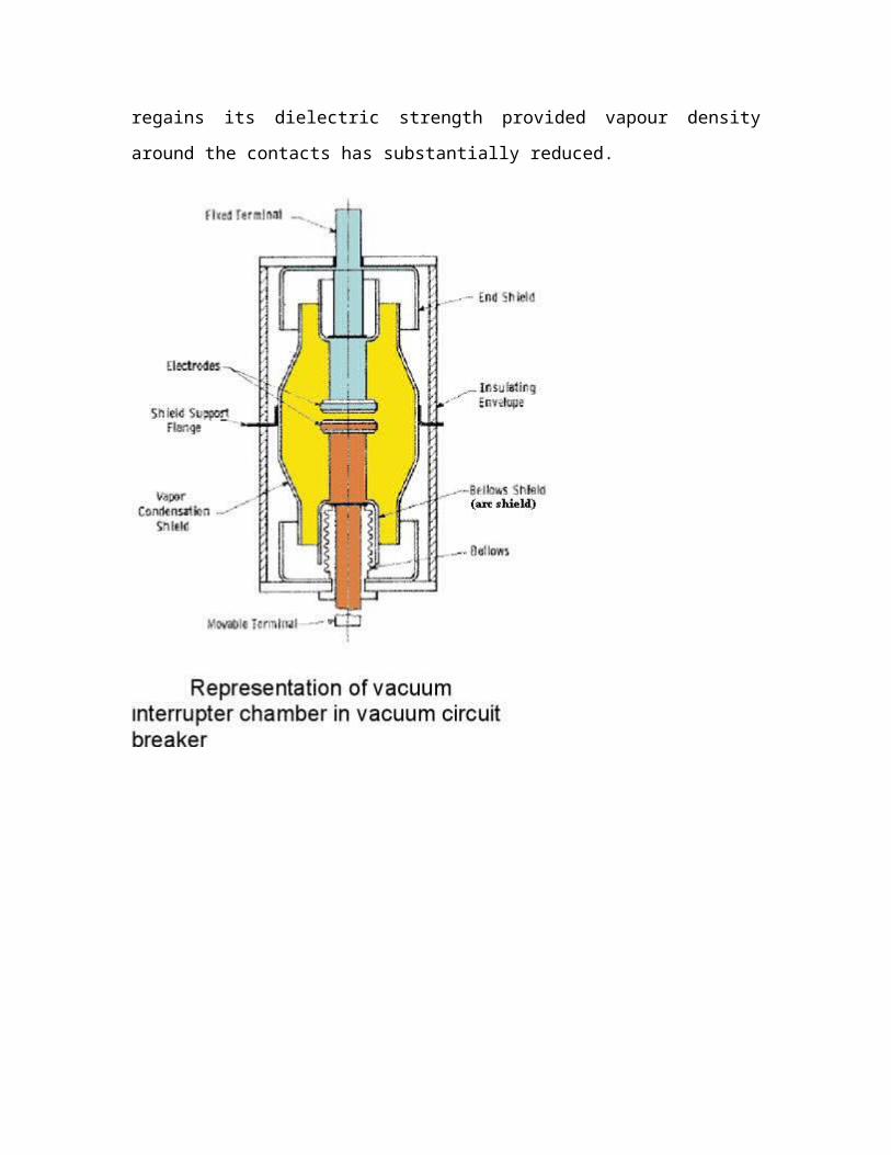
VACUUM CIRCUIT BREAKER:
As we know that when contact separation of circuit breaker arc is formed due to
ionization of particles in the medium between the contacts. Idea behind the vacuum
circuit breaker is to eliminate the medium between the contacts. The breakdown voltage
of certain contact gap varies with the absolute pressure in the vacuum interrupters.
If an arc is to be formed in vacuum, it is essential that the pressure should be low because
only then it approaches the ideal arc. The ideal arc should have a low pressure, when it is
initiated during its burning period and after its extinction.
Arc formed in vacuum is of different type from those formed in other mediums as it is
formed by the neutral atoms, ions and electrons emitted from the electrodes themselves.
The cathode surface is not perfectly smooth but has many micro projections. During the
separation of contacts the current will be concentrated in these micro projections as they
are last points of contact. Due to their small area of cross section the projections will

suffer very high heating and supply sufficient quantity of vapour for the arc formation.
As the arc is only due to the electron emission at the cathode spots and not from the entire
surface of the cathode hence the arc is called cold cathode arc.
Vacuum arc stability: In a 50 Hz ac circuit the current passes through zero value 100
times in a second. It is desirable the current is interrupted when it is passing through zero
value otherwise over voltage will be induced due to current chopping. Therefore, for
successful arc interruption it is necessary that the arc be stable for a half cycle duration
and particularly that it continues to exist at currents approaching zero. The arc stability is
found to depend upon the contact material and its vapour pressure and circuit parameters
such as voltage, current, capacitance and inductance. In low current circuits currents the
evaporation takes place from cathode and anode spots. In addition to these sources gas is
added to the enclosure of the contacts when it is stripped from other parts of the enclosure
because of high temperature and impinging metal vapour. The higher is the vapour
pressure at lower temperature, the better is the stability.
Arc extinction in vacuum interrupters
Separation of current carrying contacts causes the vapour to be released from the contacts
giving rise to plasma which is conducting medium for electric current and consists of
positive ions liberated from the contact material this vapour density depends on the
current in the arcing. During the decreasing mode of current wave the rate of release of
the vapour falls and after the current zero, the medium regains its dielectric strength
provided vapour density around the contacts has substantially reduced.
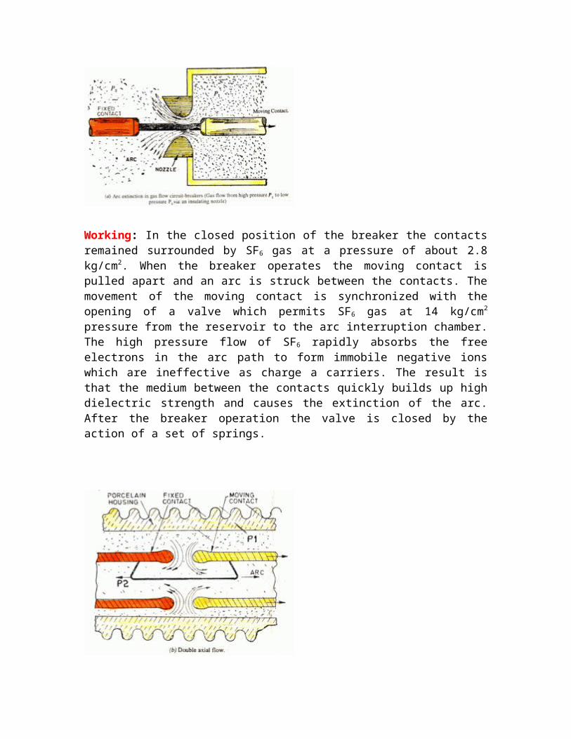
SULPHUR HEXAFLOURIDE CIRCUIT BREAKER:
Introduction: In this circuit breaker, sulphur hexaflouride ( SF6 ) gas is used as the arc quenching medium. The SF6 gas is an electro negative gas and has a strong tendency to absorb free electrons. The contacts of the breaker are opened in a high pressure flow of SF6 gas and an arc is struck between them. The conducting free electrons in the arc are rapidly captured by the gas to form relatively immobile negative ions. This loss of conducting electrons in the arc quickly builds up enough insulation strength to extinguish the arc. The SF6 circuit breakers are very effective for high power and high voltage service.
Construction: Fig 15 shows the parts of a typical SF6 circuit breaker. It consists of fixed and moving contacts enclosed in a chamber called arc interruption chamber containing SF6 gas. This chamber is connected to SF6 gas reservoir. When the contacts of breaker are opened the valve mechanism permits a high pressure SF6 gas from the reservoir to flow towards the arc interruption chamber. The fixed contact is a hollow cylindrical current carrying contact fitted with an arc horn. The moving contact is also a hollow cylinder with rectangular holes in the sides to permit the SF6 gas to let out through these holes after flowing along and across the arc. The tips of fixed contact, moving contact and arcing horn are coated with copper-tungsten arc resistant material. Since SF6 gas is costly, its reconditioned and reclaimed by a suitable auxiliary system after each operation of the breaker.
Working: In the closed position of the breaker the contacts remained surrounded by SF6
gas at a pressure of about 2.8 kg/cm2. When the breaker operates the moving contact is pulled apart and an arc is struck between the contacts. The movement of the moving contact is synchronized with the opening of a valve which permits SF6 gas at 14 kg/cm2
pressure from the reservoir to the arc interruption chamber. The high pressure flow of SF6
rapidly absorbs the free electrons in the arc path to form immobile negative ions which are ineffective as charge a carriers. The result is that the medium between the contacts quickly builds up high dielectric strength and causes the extinction of the arc. After the breaker operation the valve is closed by the action of a set of springs.
Advantages over oil and air circuit breakers:
a.) Due to superior arc quenching property of SF6 , such breakers have very short arcing time
b.) Dielectric strength of SF6 gas is 2 to 3 times that of air, such breakers can interrupt much larger currents.
c.) Gives noiseless operation due to its closed gas circuit
d.) Closed gas enclosure keeps the interior dry so that there is no moisture problem
e.) There is no risk of fire as SF6 is non inflammable
f. There are no carbon deposits
g. Low maintenance cost, light foundation requirements and minimum auxiliary equipment
h. SF6 breakers are totally enclosed and sealed from atmosphere; they are particularly suitable where explosion hazard exists
Disadvantages:
A. SF6 breakers are costly due to high cost of SF6
B. SF6 gas has to be reconditioned after every operation of the breaker, additional equipment is required for this purpose

CHAPTER 4ISOLATORS
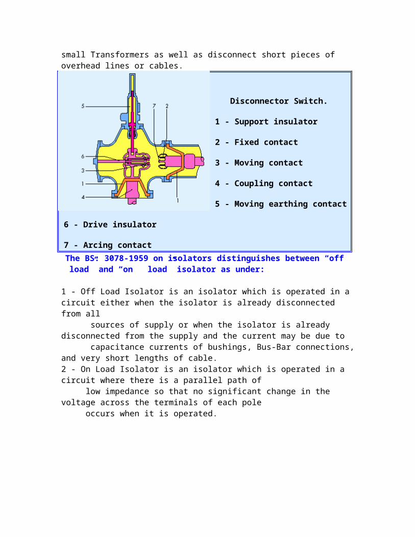
Isolating Switches are normally Switched only when not on load but they may also interrupt the no load current of small Transformers as well as disconnect short pieces of overhead lines or cables.
Disconnector Switch.
1 - Support insulator
2 - Fixed contact
3 - Moving contact
4 - Coupling contact
5 - Moving earthing contact
6 - Drive insulator
7 - Arcing contact
The BS: 3078-1959 on isolators distinguishes between “off load” and “on load” isolator as under:
1 - Off Load Isolator is an isolator which is operated in a circuit either when the isolator is already disconnected from all sources of supply or when the isolator is already disconnected from the supply and the current may be due to capacitance currents of bushings, Bus-Bar connections, and very short lengths of cable.2 - On Load Isolator is an isolator which is operated in a circuit where there is a parallel path of low impedance so that no significant change in the voltage across the terminals of each pole occurs when it is operated.
Disconnector:
1- supporting insulator
2- fixed contact
3- moving contact
4- earthing Switch
5- driving insulator
To ensure that the off load isolators are not operated inadvertently under load it is necessary that the isolators are suitably interlocked with the connected breakers. Isolating Switches can broadly be divided into the three categories given ahead.
a)Bus isolator. b) Line isolator. c)Transformer isolating.
Off Load Isolator Manual: It is a 3 Pole Off Load Isolator Manuals, which finds application in irrigation projects, process industries and mining sector. These 11KV / 33KV isolators are compact in design and have low maintenance cost.
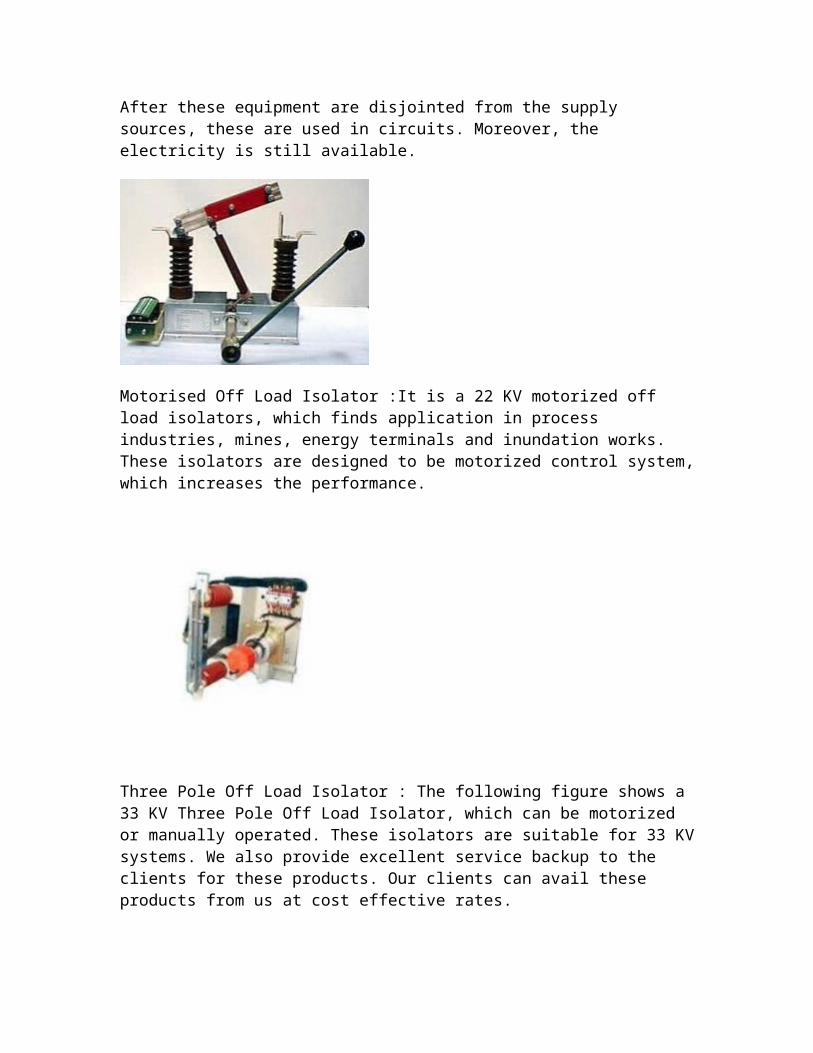
Single Pole Off Load Isolator Manual : It is a single Pole Off Load Isolator Manuals, which are cost effective. These manual equipment are widely used in 11kV or 33kV systems. After these equipment are disjointed from the supply sources, these are used in circuits. Moreover, the electricity is still available.

Motorised Off Load Isolator :It is a 22 KV motorized off load isolators, which finds application in process industries, mines, energy terminals and inundation works. These isolators are designed to be motorized control system, which increases the performance.
Three Pole Off Load Isolator : The following figure shows a 33 KV Three Pole Off Load Isolator, which can be motorized or manually operated. These isolators are suitable for 33 KV systems. We also provide excellent service backup to the clients for these products. Our clients can avail these products from us at cost effective rates.
Earthing Switch Earthing Switch is necessary to earth the conducting parts before maintenance and also to
provide deliberate short-current while testing. There can be three types of Earthing switches in
metal-clad Switches manually operated automatic high speed Earthing Switch, protective Earthing
Switch for Earthing the installation.
There are several versions of Earthing Switches for following applications
1 - Maintenance Earthing Switches. These are single pole or three pole units; manually operating
mechanism with a provision of filling motor mechanism.
2 - High Speed Earthing Switches. These are operated by spring energy. Spring is charged by motor-
mechanism
Fig (1)
Fig (2) the one pole Earthing Switch
Earthing Switch:
1- Moving contact
2- Operating lever
3- Position indicator
Closed position Open positionOpen position The earth Switch is mounted direct on the enclosure Fig. (1) Earthing Switch has to satisfy
various requirements. For Earthing isolated sections of Switchgear for protection of personal
during maintenance and over-hauls or erection, the maintenance Earthing Switches are
employed. For Earthing higher capacitances (cables, overhead line etc.) high speed Earthing
Switch are employed. Depending on the substation scheme, the Bus-Bars may be earthed either
by maintenance
or high-speed Earthing Switches.
Special high speed Earthing Switches with interrupting capability are also available. These
are suitable for interrupting capacitive and inductive currents
from parallel overhead lines. In certain cases, Earthing Switches are fitted to
the enclosure with interposed insulation.
This enables various tests to be performed on the Switchgear or item of equipment, such as
testing the current Transformer of measuring the operating time of breakers, without having to
open the enclosure. During normal operation the insulation is bypassed by a short-circuit-proof
link.

To check whether a point to be earthed really is dead, the Earthing Switch can be equipped
with a capacitive tap for connecting a voltage test unit. This additional safety device reduces the
risk of closing onto a live conductor.
CABLES BEING USED FOR DISTRIBUTION BY BSESARIAL BUNCH CABLE
This cable is an LT cable. The size of this cable is either 150 sq. mm or 95 sq. mm. The
insulation is of either PVC (Poly Vinyl Chloride) or XLPE (Cross Link Poly Ethylene).
To determine the phases, there is no colour coding in this cable instead there is present a
line coding. The phase with one line is RED, other with two line is YELLOW, next with
three lines is BLUE, next with four lines is neutral. There is present fifth wire which is
thin and used for the street lights. There is sixth wire also which is made up of steel and
is there for giving the cable a mechanical support.
S. No. Size of the cable(sq. mm)
Load for which cable isused (kW)
1 2 x 10 1-5
2 2 x 25 5-10
3 4 x 25 10-15

4 4 x 50 15-20
5 4 x 95 20-44
6 4 x 150 Above 44 for domestic use
7 4 x 300 Above 44 for industrial use
If load is more than 10 kW then 3 phase supply is given.
CHAPTER-5
FAILURES & CAUSES
Insufficient Oil level.
Seepage of water in oil.
Prolonged Over loading.
Single Phase loading.
Unbalanced loading.
Faulty Termination (Improper sized lugs etc)
Power Theft.
Prolonged Short Circuit.
Faulty operation of tap changer switch.
Lack of installation checks.
Faulty design
Poor Workmanship
Improper formation of core.
Improper core bolt insulation.
Burr to the lamination blades
Improper brazing of joints.
Burr /sharp edges to the winding conductor.
Incomplete drying.
Bad insulation covering.
Insufficient cooling ducts in the winding.
Bad Quality of raw material.
Transit damaged transformers.
MAINTENANCE PROCEDURE OF TRANSFORMER
OIL :
1. Oil level checking. Leakages to be attended.

2. Oil BDV & acidity checking at regular intervals. If acidity is between 0.5 to 1mg
KOH, oil should be kept under observation.
3. BDV, Color and smell of oil are indicative.
1. Sludge, dust, dirt ,moisture can be removed by filtration.
2. Oil when topped up shall be of the same make. It may lead to sludge formation
and acidic contents.
Insulation resistance of the transformer should be checked once in 6 months.
Megger values along with oil values indicate the condition of transformer.
Periodic Dissolved Gas Analysis can be carried out.
BUSHINGS
Bushings should be cleaned and inspected for any cracks.
Dust & dirt deposition, Salt or chemical deposition, cement or acid fumes depositions
should be carefully noted and rectified.
Periodic checking of any loose connections of the terminations of HV & LV side.
Breather examination. Dehydration of Silica gel if necessary.
Explosion vent diaphragm examination.
Conservator to be cleaned from inside after every three years.
Regular inspection of OIL & WINDING TEMPERATURE METER readings.
Cleanliness in the Substation yard with all nets, vines, shrubs removed.
CHAPTER-6
ROUTINE TESTS OF TRANSFORMER
1.Measurement of winding resistance
This test measures the resistance of the HV & LV winding. The values of resistance
should be balance for all three phases and should match the designed values.
Equipment used : Digital resistance meter.
2.Measurement of insulation resistance
Measures the insulation resistance of HV & LV windings with respect to earth (body)
and between LV & HV winding.
INSULATION TESTER OR MEGGER IS USED.
Recommended Values are
2000Mohms for HV & 500 Mohms for LV.
3.Seperate source voltage withstand test (High Voltage tests on HV & LV)- This
test checks the insulation property between Primary to earth, Secondary to earth
and between Primary & Secondary.
HV high voltage test : LV winding connected together and earthed. HV winding
connected together and given 28 KV ( for 11KV transformer) for 1 minute.
LV high Voltage test : HV winding connected together and earthed. LV winding
connected together and given 3 KV for 1 minute.
Equipment used : High Voltage tester ( 100KV & 3KV)
4.Induced Over voltage Withstand test (DVDF test)- This test checks the inter
turn insulation.
For a 11KV/433V transformer,866 Volts are applied at the 433V winding with the
help of a Generator for 1 minute. This induces 22KV on 11KV side. The frequency of the
866V supply is also increased to 100HZ.
Equipment used : MOTOR GENERATOR SET
5.Measurement of voltage ratio
This test measures the voltage ratio as per the customer’s requirement.
V1/V2 = N1/N2
The voltage ratio is equal to the turns ratio in a transformer. Using this principle, the turns
ratio is measured with the help of a turns ratio meter. If it is correct , then the voltage
ratio is assumed to be correct.
Equipment used : Turns Ratiometer
6.Measurement of NO LOAD LOSS & current.
The iron losses and no load current are measured in this test. The 433V winding is
charged at 433V supply & the 11KV winding is left open .The power consumed by the
transformer at no load is the no load loss in the transformer.
Effect of actual frequency must be taken into account.
Equipment used : Wattmeters or power analyser.
7.Measurement of LOAD LOSS & IMPEDENCE.(EFFICIENCY &
REGULATION)
This test measures the power consumed by the transformer when the 433V winding is
short circuited and The rated current is passed through the 11KV winding.
Equipment used : Wattmeters or power analyser.
8.Vector Group Verification test
This test verifies the Dyn-11 vector group of a distribution transformer.
Equipment used : voltmeter.
TRANSFORMER OIL TESTING
The life of a transformer is dependent upon three parameters

1. Temperature
2. Oxygen
3. Moisture
MOISTURE CONTENT
External moisture is repeatedly drawn into a free breathing transformer as the
working temperature rises and falls repeatedly. This moisture reduces the dielectric
strength of the paper and oil and results in the risk of electric failure.
There are few tests to determine the quality of transformer oil. Generally we use
mineral oil for transformer winding insulation and cooling hence changes in its
composition forms the basis of the test that are given as below.
Break down voltage test (BDV test)
Oil breakdown voltage is checked as per IS-335.
BDV test tests the dielectric strength of mineral oil to be used as a coolant and
insulation for the transformer windings. The apparatus for the experiment is briefly
described as below:
The kit has a bucket containing electrodes. The gap between the electrodes is kept to
be 2.5 mm. time is set for steering the oil the kit has got and inbuilt steering
mechanism. Voltage is applied between the electrodes and is gradually increased
until there is a spark flashing. The voltage at which the sparking occurs is known as
breakdown voltage of the oil.
The BDV experiment is done five times on each sample and result is taken to be
average of the readings which is generally around 60 kV.
Dissolved Gas analysis(DGA test)
This test is used to assess the condition of given transformer oil sample by doing
analysis of the gases dissolved in the oil sample. This analysis is done inside the lab
using a gas chromatograph and result is matched with the known standards. Thid
result is quite helpful in the inception of minor faults and most likely to be the cause
of major faults.
This method is very sensitive and gives an early warning of incipient faults. It is indeed
possible to determine from an oil sample of about one litre the presence of certain gases
down to a quantity of a few cubic mm , i.e., a gas volume corresponding to about 1
millionth of the volume of the liquid (ppm).
The gases (with the exception of Nitrogen and Oxygen) dissolved in the oil are derived
from the degradation of oil and cellulose molecules that takes place under the influence
of thermal and electrical stresses. Different stress modes, e.g., normal operating
temperatures, hot spots with different high temperatures, partial discharges and
flashovers, produce different compositions of the gases dissolved in the oil.
The relative distribution of the gases is therefore used to evaluate the origin of the gas
production and the rate at which the gases are formed to assess the intensity and
propagation of the gassing. Both these kinds of information together provide the
necessary basis for the evaluation of any fault and the necessary remedial action.
Oil breakdown voltage is checked as per IS-335.
Recommended value : 60KV
Equipment used : OIL BDV TEST SET.
TESTS OF CIRCUIT BREAKERS [IEC: 62271-100] 1. TYPE TESTS
S. No.
Type test Purpose
1 Dielectric testsTo check characteristics of Circuit breaker for the following tests:
I) Dry, wet, power frequency
II) Lightning impulse voltage
III) Switching impulse voltage( applicable for 420 kV CB and above)
2 Radio Interference voltage test
To determine RIV on CB pole in both close & open position
3 Resistance of the main circuit
To record circuit resistance during temp. rise test at 200 C
4 Temp. rise test To ensure capability of contacts to carry rated normal current within specified temp.
rise limits
5 Short-time withstand current & peak withstand current
To check the ability of the circuit to carry the maximum rated short-circuit withstand current ( 2.5 times the RMS value) at 50 Hz in close position during the specified short-term duration of 1 or 3 sec.
6 Mechanical operation test at ambient temp.
To check the characteristics of the breaker for 2000 operations on each pole ( with multiple circuit breaker with individual drive) OR complete assembled breaker (mechanically gang-operated breaker with one common drive)
7 Short-circuit current making/ breaking tests
To check ability of the CB to clear the current on different tests in symmetrical & asymmetrical conditions as per provisions of IEC
8Capacitive current charging tests:
-Line charging current breaking tests
-Cable charging current breaking tests
To check withstand capability of the CB for no load transient lines, cables , and capacitor banks
2. ROUTINE TESTS
S. No.
Routine test Purpose
1 Dielectric test on main circuit
To check the dielectric’s withstand capability of live terminals to live terminals and to earth in both close & open condition of CB
2 Dielectric test on auxiliary & control circuit
To check the dielectric’s withstand capability of auxiliary & control circuit of CB subject to short duration (60 sec) voltage withstand test for 2 kV . ( For

motor or other devices , they are subjected to a dielectric test as per appropriate specs.)
3 Design identification
test
Verifies the CB for compliances in terms
of language of name plate, identification of
aux. Equipment, colour & quality of paint
etc.
4 Mechanical operating
test
Includes
1) 5 open-close operations at max.
rated and minimum control voltage
2) 5 close-open operation at rated
control voltage
3) recording opening & closing
times at the rated operating pressure
& voltage
5 Measurement of
resistance of main
circuit
To record contact resistance of CB for
mechanical operations to be within
specified limits


![BSES YAMUNA POWER LIMITED - DERCderc.gov.in/ordersPetitions/orders/Tariff/Tariff Order/Tariff Order for... · BSES YAMUNA POWER LIMITED [TARIFF ORDER FY 2018-19] DELHI ELECTRICTY](https://img.dokumen.tips/doc/110x75/5ea70ac446c617793b42c7ae/bses-yamuna-power-limited-ordertariff-order-for-bses-yamuna-power-limited.jpg)