Embed Size (px)
Citation preview

BRU-200 and BRU-500Brushless Drives
Instruction Manual
Electro-Craft Servo ProductsR

(
r r
( ( Electro-Craft
BRU-200 and BRU-500 Brushless Drives
Instruction Manual
P/N 0013-1028-001 Revision B
Reliance Motion Control, Inc. 6950 Washington Avenue South
Eden Prairie, MN 55344 612-942-3600
Technical Support: 800-328-3983
DANGER ONLY QUALIFIFED ELECTRICAL PERSONNEL FAMILIAR WITH THE
CONSTRUCTION AND OPERATION OF THIS EQUIPMENT AND THE HAZARDS INVOLVED SHOULD INSTALL, ADJUST, OPERATE OR SERVICE THIS EQUIPMENT. READ AND UNDERSTAND THIS MANUAL AND OTHER APPLICABLE MANUALS IN
THEIR ENTIRETY BEFORE PROCEEDING. FAILURE TO OB_SERVE THIS PRECAUTION COULD RESULT IN SEVERE BODILY INJURY OR LOSS OF LIFE.
WARNING THE USER MUST PROVIDE AN EXTERNAL, HARDWIRED EMERGENCY STOP
CIRCUIT OUTSIDE THE CONTROLLER CIRCUITRY THIS CIRCUIT MUST DISABLE THE SYSTEM IN CASE OF IMPROPER OPERATION. UNCONTROLLED MACHINE
OPERATION MAY RESULT IF THIS PROCEDURE IS NOT FOLLOWED. FAILURE TO OBSERVE THIS PRECAUTION COULD RESULT IN SEVERE BODILY INJURY.
Copyright© Reliance Motion Control, Inc. 1995. All rights reserved.
The information contained in this manual is subject to change without notice.
Electro-Craft is a registered trademark of Reliance Electric Company or its subsidiaries. Tandy is a registered trademark of Tandy Corporation. IBM is a registered trademark of International Business Machines Corporation. INTEL is a trademark of Intel Corporation. AMP is a trademark of AMP Incorporated. Molex is a registered trademark of Molex Incorporated.
(
(
(
(
r Table of Contents
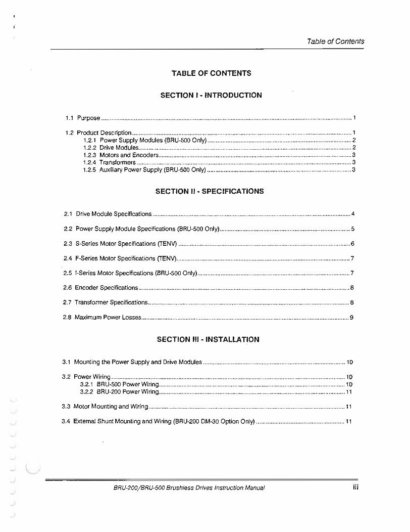
TABLE OF CONTENTS
SECTION I - INTRODUCTION
1.1 Purpose ......................................................................................................................................................... 1
1.2 Product Description .......................................................................................................... ............................ 1 1.2.1 Power Supply Modules (BRU-500 Only) ........................................................................................ 2 1.2.2 Drive Mcx:lules .................................................................................................................................. 2 1.2.3 Motors and Encoders ...................................................................................................................... 3 1.2.4 Transformers ................................................................................................................................... 3 1.2.5 Auxiliary Power Supply (BRU-500 Only) ........................................................................................ 3
SECTION 11- SPECIFICATIONS
2.1 Drive Mcx:lule Specifications ......................................................................................................................... 4
2.2 Power Supply Module Specifications (BRU-500 Only) .................... ............................................................ 5
2.3 S-Series Motor Specifications (TENV) ............................................................................................ ............. 6
2.4 F-Series Motor Specifications (TENV) .......................................................................................................... 7
2.5 1-Series Motor Specifications (BRU-500 Only) ............................................................................................. 7
2.6 Encoder Specifications ................................................................................................................................. 8
2. 7 Transformer Specifications ........................................................................................................................... 8
2.8 Maximum Power Losses ............................................................................................................................... 9
SECTION Ill-INSTALLATION
3.1 Mounting the Power Supply and Drive Modules ........................................ ............................................... 10
3.2 Power Wiring ............................................................................................................................................... 10 3.2.1 BRU-500 Power Wiring .................................................................................................................. 1 0 3.2.2 BRU-200 Power Wiring .............................................................. .................................................... 11
3.3 Motor Mounting and Wiring ........................................................................................................................ 11
3.4 External Shunt Mounting and Wiring (BRU-200 DM-30 Option Only) ...................................................... 11
BRU-200/BRU-500 Brushless Drives Instruction Manual iii

Table of Contents
SECTION IV - INTERFACE CIRCUITRY
4.1 Drive Module Interface Connectors ............................................................................................................ 15
4.2 Drive Module Interface Signal Specifications ............................................................................................ 16
4.3 Power Supply Module Interface Connector (BRU-500 Only) .................................................................... 20
4.4 Power Supply Module Interface Signal Specifications (BRU-500 Only) ................................................... 20
SECTION V- START-UP AND ADJUSTMENTS
5.1 Initial Start-Up Procedure ........................................................................................................................... 21 5.1.1 Initial Start-Up Procedure (BRU-500) ...................................... ..................................................... 21 5.1.2 Initial Start-Up Procedure (BRU-200) ........................................................................................... 22
5.2 Adjustments ................................................................................................................................................. 23 5.2.1 Power Supply Module Adjustments (BRU-500 Only) .................................................................. 23 5.2.2 Drive Module Adjustments ............................................................................................................ 23 5.2.3 Serial Interface Operation ................................................................................ ............................. 27
5.2.3.1 User Terminal Requirements .......................................................................................... 27 5.2.3.2 Operating the User Terminal. .......................................................................................... 27
5.2.3.2.1 Help Page .......................................................................................................... 27 5.2.3.2.2 Status Page ........................................................................................................ 29 5.2.3.2.3 Setup Page ........................................................................................................ 31
5.2.3.3 Multi-Drop Host Mode Serial Protocol ........................................................................... 35
5.3 Tuning Procedure ........................................................................................................................................ 36 5.3.1 Using Auto-Tune Mode ................................................................................................................. 36 5.3.2 Using Tune Mode .......................................................................................................................... 38
5.4 Personality Module Installation ................................................................................................................... 43
SECTION VI -TROUBLESHOOTING AND MAINTENANCE
6.1 Introduction ................................................................................................................................................. 44
6.2 LED Diagnostic lnfonnation ........................................................................................................................ 44 6.2.1 Power Supply Module LEOs (BRU-500 Only) .............................................................................. 44 6.2.2 Drive Module LEOs ........................................................................................................................ 44
6.3 Serial Unk Diagnostic Information .............................................................................................................. 45
iv BRU-200/BRU-500 Brushless Drives Instruction Manual
r (
(
Table of Contents
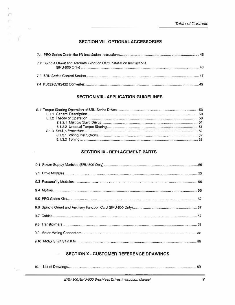
SECTION VII - OPTIONAL ACCESSORIES
7.1 PRO-Series Controller Kit Installation Instructions .................................................................................... 46
7.2 Spindle Orient and Auxiliary Function Card Installation Instructions (BRU-500 Only) .............................................................................................................................. 46
7.3 BRU-Series Control Station ........................................................................................................................ 47
7.4 RS232C/ RS422 Converter .......................................................................................................................... 49
SECTION VIII- APPLICATION GUIDELINES
8.1 Torque Sharing Operation of BRU-Series Drives ..................................................................... .................. 50 8.1.1 General Description .......................................................................... ............................................ 50 8.1 .2 Theory of Operation ...................................................................................................................... 50
8.1.2.1 Multiple Slave Drives ....................................................................................................... 51 8.1 .2.2 Unequal Tor que Sharing .................................................................................. ............... 51
8.1.3 Set-Up Procedure .......................................................................................................................... 52 8.1.3.1 Wiring Instructions ........................................................................................................... 52 8.1.3.2 Tuning .............................................................................................................................. 52
SECTION IX- REPLACEMENT PARTS
9.1 Power Supply Modules (BRU-500 Only) ................................................................................................. ... 55
9.2 Drive Modules .............................................................................................................................................. 55
9.3 Personality Modules .................................................................................................................................... 56
9.4 Motors .......................................................................................................................................................... 56
9.5 PRO-Series Kits ........................................................................................................................................... 57
9.6 Spindle Orient and Auxiliary Function Card (BRU-500 Only) .................................................................... 57
9. 7 Cables .................................................................................................................................................. ........ 57
9.8 Transformers ............................................................................................................................................... 58
9.9 Motor Mating Connectors ........................................................................................................................... 58
9.10 Motor Shaft Seal Kits ............... .................................................................................................................. 58
SECTION X- CUSTOMER REFERENCE DRAWINGS
10.1 List of Drawings ...................................................................................... ................................................... 59
BRU-200/BRU-500 Brushless Drives Instruction Manual v
Table of Contents
INDEX
Index ................................................................................................................................................................... 54
LIST OF FIGURES
Figure 1-1 BRU-500 Series Servo and Spindle Drives ................................................................ ....................... 1
Figure 1-2 BRU-200 Series Servo Drives ............................................................................................................ 2
Figure 3-1 S-Series Motor Connections ........................................................................................................... 12
Figure 3-2 F-Series Motor Connections ........................................................................................................... 13
Figure 3-3 I -Series Motor Connections ............................................................................................................ 14
Figure 5-1 PSM Jumper Locations •.................................................................................... .............................. 25
Figure 5-2 OM Jumper and Personality Module Locations ...................... ....................................................... 26
Figure 5-3 Serial Terminal HELP PAGE ............................................................................................................ 28
Figure 5-4 Software and Personality Module Identification ............................................................................. 28
Figure 5-5 Serial Terminal STATUS PAGE ....................................................................................................... 29
Figure 5-6 Serial Terminal STATUS PAGE After Fault ..................................................................................... 29
Figure 5-7 Serial Terminal SETUP PAGE (Velocity Mode) .............................................................................. 31
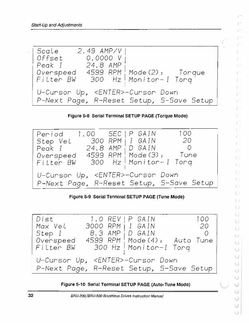
Figure 5-8 Serial Terminal SETUP PAGE (Torque Mode) ............................................................................... 32
Figure 5-9 Serial Terminal SETUP PAGE (Tune Mode) ................................................................................... 32
Figure 5-10 Serial Terminal SETUP PAGE (Auto-Tune Mode) ........................................................................ 32
Figure 5-11 Control Block Diagrams of Operating Modes ........................................ ................ ...................... 39
Figure 5-12 Typical Small-Signal Response for Well-Tuned System .............................................................. 42
Figure 5-13 Personality Module lnstallation ..................................................................................................... 43
Figure 7-1 Spindle Orient and Auxiliary Function Application (BRU-500 Only) .............................................. 46
Figure 7-2 BRU-Series Control Station ............................................................................................................. 47
Figure 7-3 BRU-Series Control Station Connection Diagram ......................................................................... 48
vi BRU-200/BRU-500 Brushless Drives Instruction Manual
(
Table of Contents
LIST OF FIGURES (Cont.)
Figure 8-1 Examples of Torque Sharing Operation ......................................................................................... 51
Figure 8-2 Recommended Wiring for Torque Sharing when Motors Rotate in Same Direction ....................................... .......................................................... 53
Figure 8-3 Recommended Wiring for Torque Sharing when Slave Motors Rotate Opposite of Master Motor ............................................................................................. 54
Figure 9-1 Personality Module Model Number Description ............................................................................ 56
Figure 9-2 Motor Model Number Description .................................................................................................. 56
LIST OF APPENDICES
APPENDIX A- Getting Started With the Tandy 102 Terminal .......................................................................... 60
APPENDIX 8- User Terminal Communication Codes ..................................................................................... 61
APPENDIX C Getting Started With an IBC PC Terminal... ............................................................................... 62
APPENDIX D Communication Problems and Possible Cures ........................................................................ 63
BRU-200/BRU-500 Brushless Drives Instruction Manual vii

(
l

(
r Introduction
SECTION I - INTRODUCTION
1.1 Purpose
This manual describes the Electro-Craft BRU-Series brushless servo drives and spindle drives along with standard Electro-Craft motors recommended for use with the BRU-Series drives. The manual is intended for use by qualified engineers or technicians directly involved in the installation, operation, and field level maintenance of the drives and motors.
1.2 Product Description
The BRU-500 is a high performance sinusoidal brushless industrial drive employing a modular package suited to single or multi-axis applications. The drive modules can powerS-Series and F-Series permanent magnet synchronous motors as servo drives or 1-Series squirrel cage induction motors as spindle drives. All drives share a common power supply to achieve the most economical system package. 1-1 shows the standard BRU-500 components.
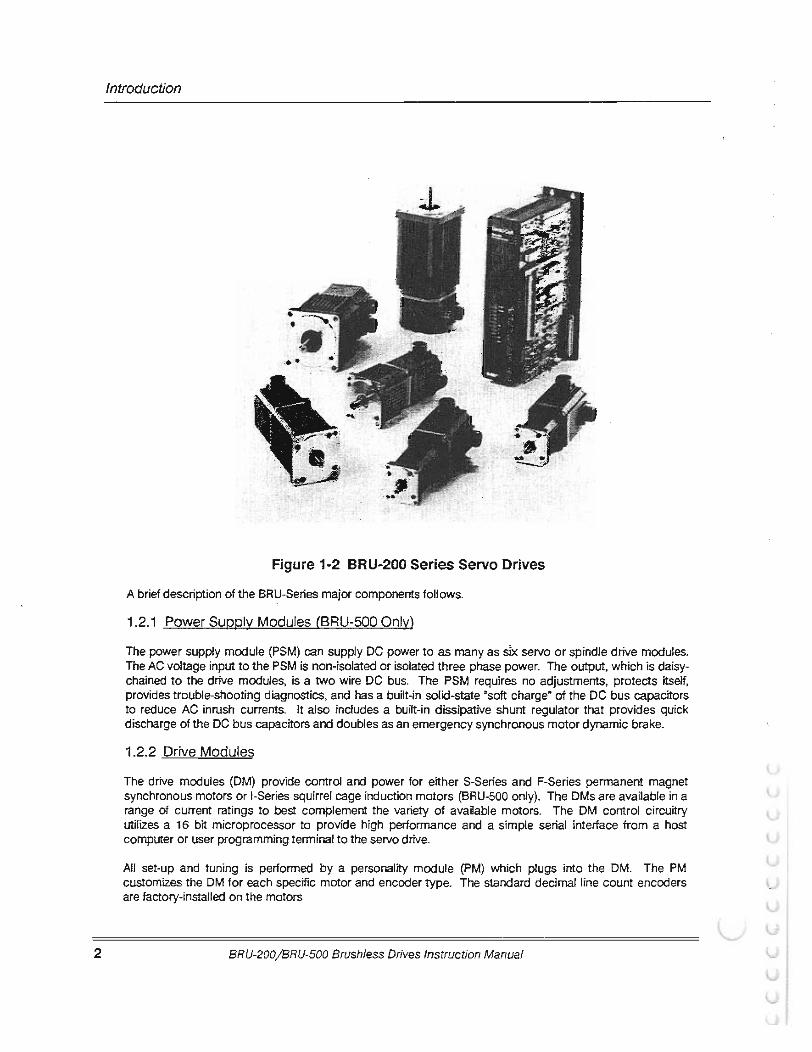
The BRU-200 is a high performance sinusoidal brushless industrial drive employing a modular package suited to single or multi-axis applications. The drive modules power S-Series and F-Series permanent magnet synchronous motors. Figure 1-2 shows the standard BRU-200 components.
For single axis positioning applications, the Electro-Craft PRO-Series controller cards are available as PRO-Series Controller Kits to be integrated into the BRU-Series drive module. This eliminates the need for a separate controller package.
Figure 1-1 BRU-500 Series Servo and Spindle Drives
BRU-200/ BRU-500 Brushless Drives Instruction Manual 1
2
Introduction
Figure 1-2 BRU-200 Series Servo Drives
A brief description of the BRU-Series major components follows.
1.2.1 Power Supply Modules (BRU-500 Only)
The power supply module (PSM) can supply DC power to as many as slx servo or spindle drive modules. The AC voltage input to the PSM is non-isolated or isolated three phase power. The output, which is daisy-chained to the drive modules, is a two wire DC bus. The PSM requires no adjustments, protects itself, provides trouble-shooting diagnostics, and has a built-in solid-state "soft charge• of the DC bus capacitors to reduce AC inrush currents. It also includes a built-in dissipative shunt regulator that provides quick discharge of the DC bus capacitors and doubles as an emergency synchronous motor dynamic brake.
1.2.2 Drive Modules
The drive modules (OM) provide control and power for either S-Series and F-Series permanent magnet synchronous motors or !-Series squirrel cage induction motors (BRU-500 only). The OMs are available in a range of current ratings to best complement the variety of available motors. The OM control circuitry utilizes a 16 bit microprocessor to provide high performance and a simple serial interface from a host computer or user programming terminal to the servo drive.
All set-up and tuning is performed by a personality module (PM) which plugs into the DM. The PM customizes the DM for each specific motor and encoder type. The standard decimal line count encoders are factory-installed on the motors.
BRU-200/BRU-500 Brushless Drives Instruction Manual
r Introduction
A standard RS-232/RS-422 serial interface is used to modify tuning, change limit values, or monitor variables/status in the BRU-Series drive modules. Any changes made through the serial interface can then be stored in the PM. A VT-52 compatible serial terminal is required for the easy-to-use menus. Refer to Section 5.2.3.1 for user terminal requirements. Alternatively, a multi-drop host mode communication protocol is also available for direct connection to computer hosts. Refer to Section 5.2.3.3.
1.2.3 Motors and Encoders
A wide range of Electro-Craft S-Series and F-Series permanent magnet synchronous motors and 1-Series induction motors are available for use with BRU-Series drives. Each motor includes an internally mounted encoder. The BRU-Series also provides the encoder signals for the position controller to use for the most economical system. Most motors are available with optional spring-set brake, optional shaft oil seals, and/or optional fanpack. The synchronous motors have a rear shaft available for mounting optional feedback devices.
1.2.4 Transformers
Multi-tap three phase isolation transformers are available in a variety of power ratings for line voltage matching for the BRU-500. A multi-tap single phase isolation transformer is available for line voltage matching for the BRU-200.
1.2.5 Auxiliary Power Supply
An auxiliary power supply module (PSM-AUX) is available to supply DC power to the logic supplies of up to four DMs if the PSM is turned off. The PSM-AUX uses single phase 115 VAC power as the input.
The PSM-AUX option is used if DM logic power must stay on even when the motor supply (the PSM) is turned off. Absolute positioning with PRO-Series controller kits is one example where the PSM-AUX would be used. Another example would be maintaining DM logic power so that the DM serial interface could be used for trouble-shooting and diagnostics. See drawing 91 01-0134 in Section X for additional information on use of the PSM-AUX and the optional PSM-AUX isolation transformer.
The auxiliary power supply is built into the BRU-200 drive modules as standard equipment. See drawing 91 01-1329 in Section X for additional information.
BRU-200/BRU-500 Brushless Drives Instruction Manual 3
4
Specifications
SECTION II - SPECIFICATIONS
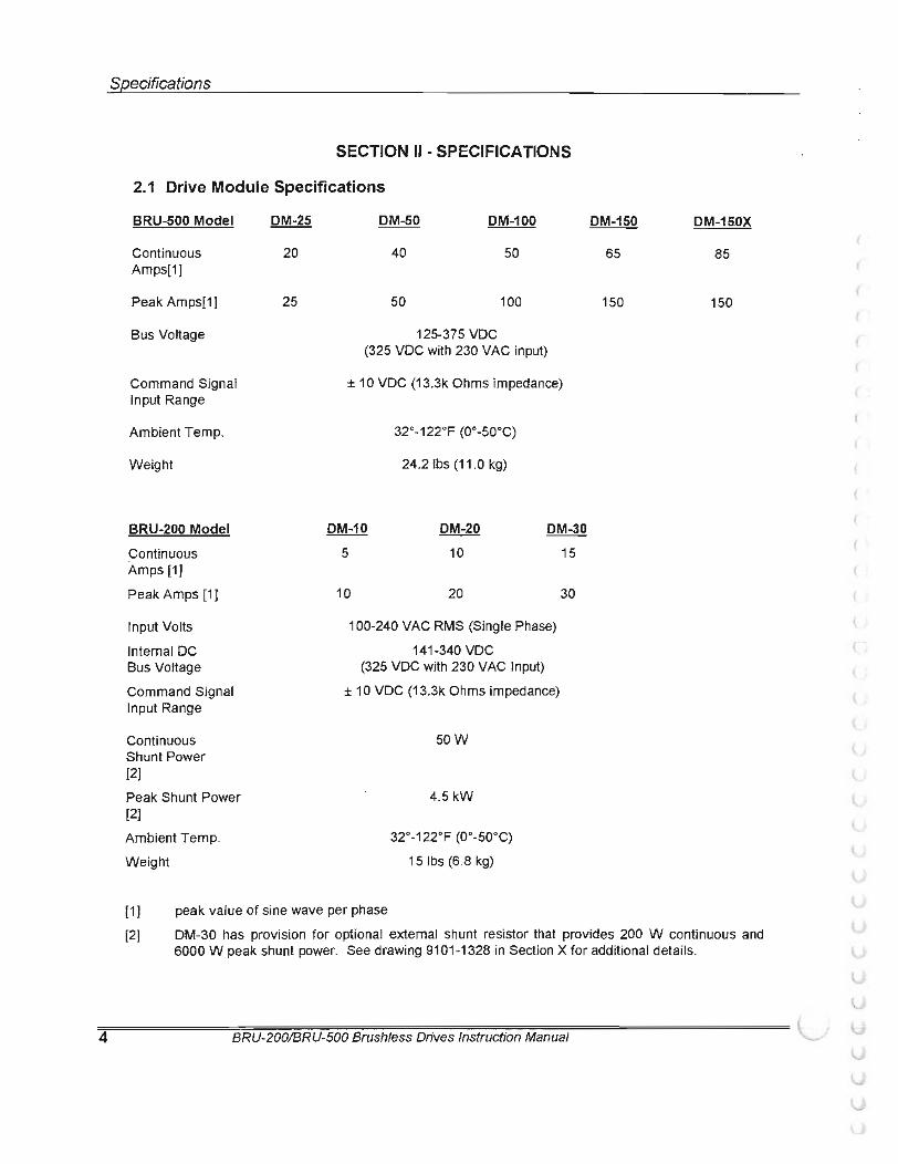
2.1 Drive Module Specifications
BRU-500 Model
Continuous Amps[1]
Peak Amps[1 I
Bus Voltage
Command Signal Input Range
Ambient Temp.
Weight
BRU-200 Model
Continuous Amps [1]
Peak Amps [1 1
Input Volts
Internal DC Bus Voltage
Command Signal Input Range
Continuous Shunt Power [21 Peak Shunt Power [21 Ambient Temp.
Weight
DM-25
20
25
DM-50 DM-100
40 50
50 100
125-375 VDC (325 VDC with 230 VAC input)
± 10 VDC (13.3k Ohms impedance)
32o-122oF (0°-50°C)
24.2 lbs (11 .0 kg)
DM-20
10 DM-30
15
10 20
100-240 VAC RMS (Single Phase)
141-340 VDC (325 VDC with 230 VAC Input)
± 10 VDC (13.3k Ohms impedance)
sow
4.5kW
32°-122oF (0°-50°C)
15 lbs (6.8 kg)
30
peak value of sine wave per phase
DM-150 DM-150X
65 85
150 150
[1 1 [2] DM-30 has provision for optional external shunt resistor that provides 200 W continuous and
6000 W peak shunt power. See drawing 9101-1328 in Section X for additional details.
BRU-200/BRU-500 Brushless Drives Instruction Manual
(
(
Specifications
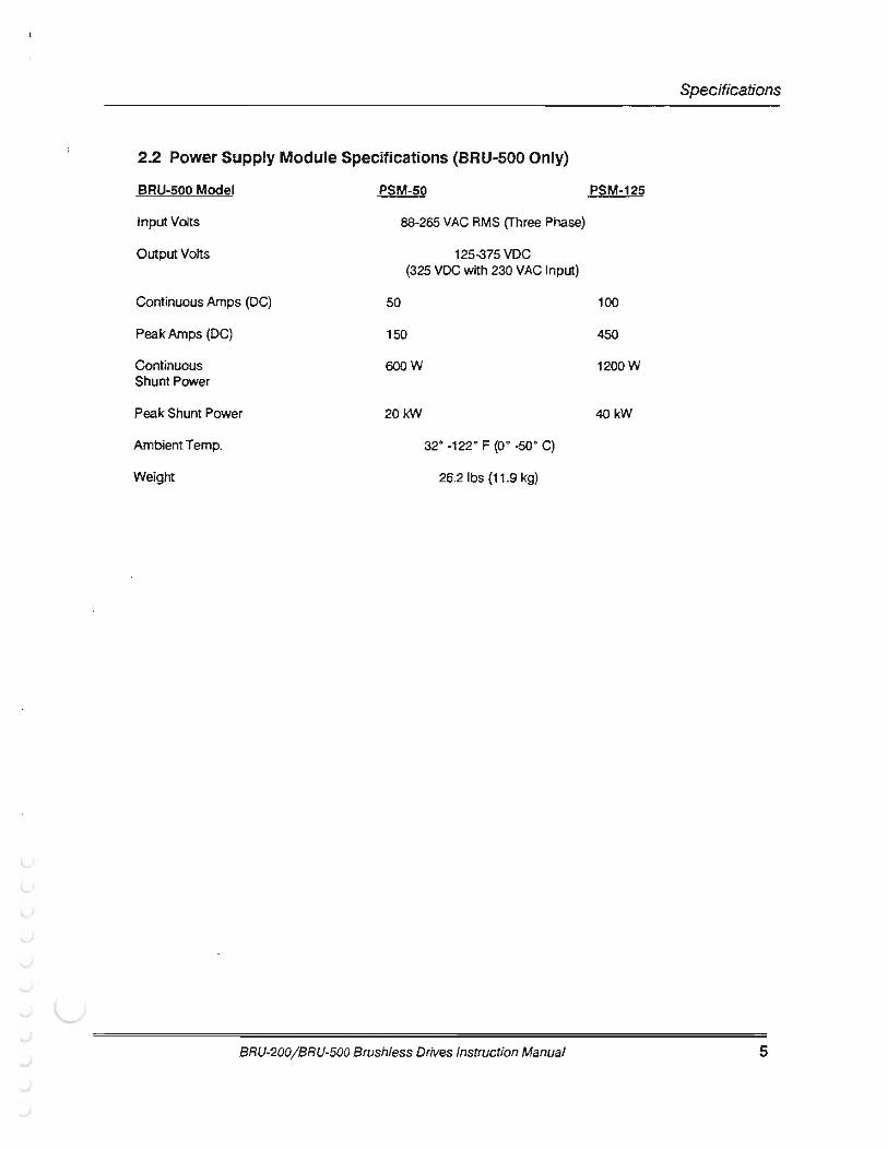
2.2 Power Supply Module Specifications {BRU-500 Only)
BRU-500 Model PSM-50 PSM-125
Input Volts 88-265 VAC RMS (Three Phase)
Output Volts 125-375 VDC (325 VDC with 230 VAC Input)
Continuous Amps (DC) 50 100
Peak Amps (DC) 150 450
Continuous 600W 1200W Shunt Power
Peak Shunt Power 20kW 40kW
Ambient Temp. 32· -122· F (o• -so· C)
Weight 26.2 lbs (11 .9 kg)
BRU-200/ BRU-500 Brush/ess Drives Instruction Manual 5
6
Specifications
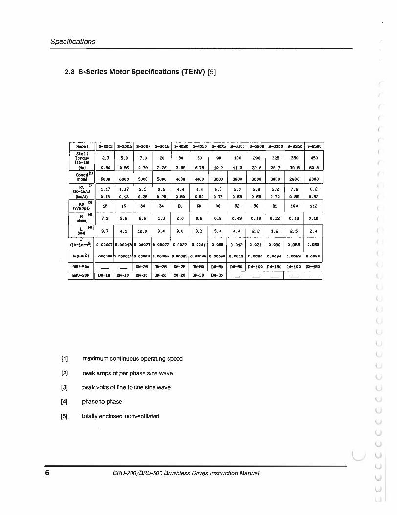
2.3 S-Series Motor Specifications (TENV} [5]
[1 1 [2]
[3]
[4]
[SJ
Model S-2003 5-2005 5-3007 S-3016 5-4030 stall
Torque (ll>-inl
2. 7 5. 0 7. 0 20 30
(Mal 0.30 0.56 0.79 2. 26 3.39 Speed 00 (rpll) 6000 6000 5000 5000 4000 Kt 121
1. 17 1.17 2.5 2.5 4. 4 (Ha/A) 0.13 0. 13 0 .28 0.28 0.50
Ke C3l (V/lCrpll) 16 16 34 34 60
A lohu) 7.3 2.6 6.6 1.3 2.0
L t.HI 9.7 4.1 12.0 3 . 4 9.0
J (lll-1n-s2J 0. 00007 0.00013 0.00027 0.00072 0.0022
(kg-112) .000008 0.00003 0.00008 0.00025
BRU-500 - - DM-25 Dlt-25 DM-25 BRU-200 DM-10 DM-10 DM-10 DM-20 DM-20
maximum continuous operating speed
peak amps of per phase sine wave
peak volts of line to line sine wave
phase to phase
totally enclosed nonventilated
5-4050 5-4075
60 90
6. 78 10.2
4000 3000
4.4 6 .7 0 .50 0.76
60 90
0.8 0.9
3.3 5.4
0.0041 0.006
0.00046 0.00068
DM-50 DM-50 DM-30 OM-30
S-6100 S-6200
100 200
11.3 22.6
3000 3000
6 .0 5 .8 0.68 0.66
82 80
0.49 0. 18
4.4 2 . 2
0.012 0.021
0.0013 0.0024
llM-50 DM-100
- -
BRU-200jBRU·500 Brushless Drives Instruction Manual
(
(
S-6300 S-8350 s-esoo
325 350 450
36.7 39.5 50.8
3000 2000 2000
6.2 7 . 6 8 . 2 0.70 0.86 0 . 92
85 104 112
0.12 0 . 13 0 . 10
1 .2 2 .5 2 . 4
0.030 0.056 0.083
0 .0034 0.0063 0.0094
DM-150 DM-100 DM-150
- - -

r Specifications
2.4 F-Series Motor Specifications (TENV) [5]
HodeL F-4030 F-fOSO F-4075 F-6100 F-6200 F-6300 StaLL
31 6l 82 1l5 175 245
a.> 3.5 6. 9 9.3 t3.0 19.8 27.8
4000 4000 3000 3000 3000 3000
J::t (2)
Clb-lniA> 4.8 4.8 6.5 6.3 6.2 6.5 (IWA) 0.54 0.54 0.73 0. 11 0. 10 0.73
ao CV/Itrpa) 66 66 89 86 8S 89
R C4l (en.> 2.24 0.89 0.98 o.51 0.26 0.16
L C4l c.tO 6.8 3.3 3.<1 3. 3 1. 7 1.1
J Clb-1,...2) 0.009 0.019 0.029 0.057 o.oss O.t<l.f ctv--2 > 0. 001 o.002t 0.0032 0.0064 0.0107 0.0162
8R0-500 DI'I-2S 01'1-50 01'1-50 01'1-50 01'1-100 01'1-100
BRU-200 01'1-20 01'1-30 DH-30 - - -
(1] maximum continuous operating speed [2] peak amps of per phase sine wave [3] peak volts of line to line sine wave (4] phase to phase [5] totally enclosed nonventilated
2.5 1-Series Motor Specifications (BRU-500 Only)
Cont. 30 Hin. Bose Hox. Rotor HodeL Power Rot ing Speed Speed Inertia Weight Drive
Kg-m2f kg/Lbs Module kWIHP kWIHP RPH RPH lb-in-s2
I-5300 5. 517.4 7.5110 . 0 7500 6000 0.037 / 701154 DH-100 TEA00 ) 0.269
I-6600 11/14.7 15120 7500 6000 0.0731 108/ 238 DH-150X TEA00 ) 0.643
[ 1] totally enclosed air over (TEAO)
BRU-200/BRU-500 Brushless Drives Instruction Manual 7
8
Specifications
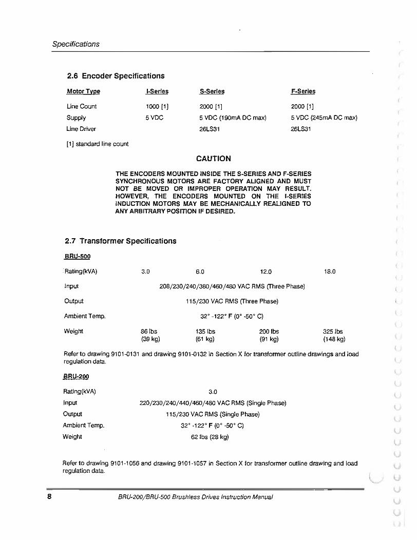
2.6 Encoder Specifications
Motor Type 1-Series S-Series F-Series
2000 [1] 2000 [1] UneCount
Supply
Une Driver
1000 [1]
5VDC 5 VDC (190mA DC max) 26LS31
5 VDC (245mA DC max)
26LS31
{1) standard line count
CAUTION
THE ENCODERS MOUNTED INSIDE THE S-SERIES AND F-SERIES SYNCHRONOUS MOTORS ARE FACTORY AUGNED AND MUST NOT BE MOVED OR IMPROPER OPERATION MAY RESULT. HOWEVER, THE ENCODERS MOUNTED ON THE I-SERIES INDUCTION MOTORS MAY BE MECHANICALLY REAUGNED TO ANY ARBITRARY POSITION IF DESIRED.
2.7 Transformer Specifications
BRU-500
. Rating(kVA) 3.0 6.0 12.0
Input 208/230/240/380/460/480 VAC RMS (Three Phase)
Output 115/230 VAC RMS (Three Phase)
Ambient Temp. 32°-122° F (0° -sao C)
Weight 86lbs 1351bs 200ibs (39 kg) (61 kg) (91 kg)
18.0
325lbs (148 kg)
Refer to drawing 9101-0131 and drawing 9101-Q132 in Section X for transformer outline drawings and load regulation data.
BRU-200
Rating(kVA)
Input
Output
Ambient Temp.
Weight
3.0
220/230/240/440/460/480 VAC RMS (Single Phase)
115/230 VAC RMS (Single Phase) 32° -122° F (Oo -sao C)
62 lbs (28 kg)
Refer to drawing 9101-1056 and drawing 9101-1057 in Section X for transformer outline drawing and load regulation data.
BRU-200/BRU-500 Brushless Drives Instruction Manual
(
(
r Specifications
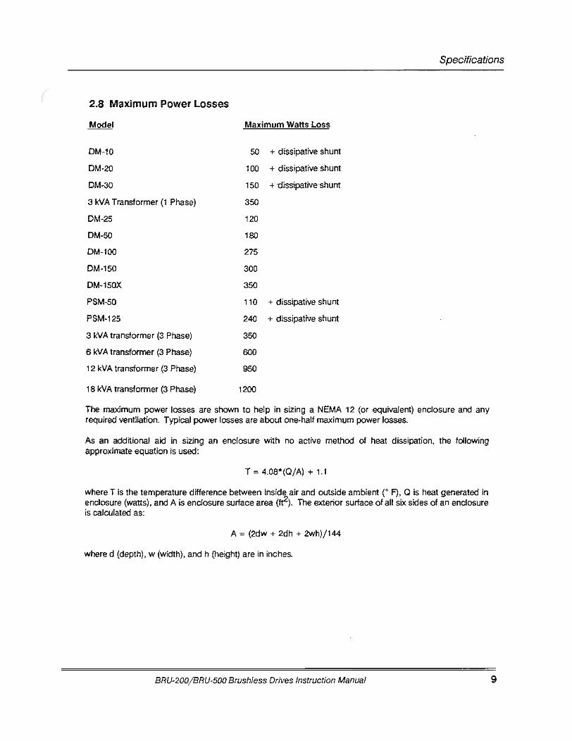
2.8 Maximum Power Losses
Maximum Watts Loss
DM-10 50 + dissipative shunt
DM-20 100 + dissipative shunt
DM-30 150 +·dissipative ·shunt
3 kVA Transformer (1 Phase) 350
DM-25 120
DM-50 180
DM-100 275
DM-150 300
DM-150X 350
PSM-50 110 + d issipative shunt
PSM-125 240 + dissipative shunt
3 kVA transformer (3 Phase) 350
6 kVA transformer (3 Phase) 600
12 kVA transformer (3 Phase) 950
18 kVA transformer (3 Phase) 1200
The maximum power losses are shown to help in sizing a NEMA 12 (or equivalent) enclosure and any required ventilation. Typical power losses are about one-half maximum power losses.
As an additional aid in sizing an enclosure with no active method of heat dissipation, the following approximate equation is used:
T = 4.08*(0/ A) + 1.1
where T is the temperature difference between inside air and outside ambient (" F), Q is heat generated in enclosure (watts), and A is enclosure surface area (tt2). The exterior surface of all six sides of an enclosure is calculated as:
A = (2dw + 2dh + 2wh)/ 144
where d (depth), w (width), and h (height) are in inches.
BRU-200/BRU-500 Brushless Drives Instruction Manual 9

Installation
10
SECTION Ill-INSTALLATION
3.1 Mounting the Power Supply and Drive Modules
The BRU-500 power supply and drive modules and BRU-200 drive modules are designed for simple installation on a flat surface such as the back wall or plate of an enclosure. The environment in the enclosure must be clean and free of oil mist, coolant mist, conductive particles, and corrosive chemicals. For industrial applications, a NEMA 12 or equivalent enclosure is recommended. The enclosure must also be properly sized (and ventilated if required) to insure that the BRU-500 and BRU-200 maximum ambient temperature is not exceeded.
Drawings 91 01-0409 and 91 01-0410 illustrates a typical BRU-500 installation showing space requirements between modules for cover removal and around modules for wiring and air flow. The power supply module should be centrally located to minimize the distance between it and the drive modules. It is also recommended that the higher current rating drive modules be located closest to the power supply module.
Drawing 9101-1300 shows the BRU-200 drive module dimensions including space requirements around the drive module for wiring and air flow.
3.2 Power Wiring 3.2.1 BRU-500 Power Wiring
WARNING DANGER OF ELECTRICAL SHOCK OR BURN. ONLY QUALIFIED INDIVIDUALS SHOULD WORK ON THIS EQUIPMENT. DISCONNECT ALL POWER BEFORE WORKING ON EQUIPMENT. DANGEROUS VOLTAGES MAY EXIST AFTER POWER IS REMOVED! CHECK DC BUS VOLT AGE OF BRU-500 EACH TIME POWER IS REMOVED BEFORE WORKING ON EQUIPMENT.
Drawing 9101-0411 illustrates the only required power wiring for a typical four axis installation. The phasing of the three phase input L 1, L2, and L3 to the power supply module is arbitrary, but the DC bus+ and - polarities must be connected as shown. Also, the phasing of the three phase drive module outputs R, S, and T must conform to the motor R, S, and T leads for proper operation. Connect the earth ground as shown to insure a safe and proper installation.
The DC bus connection wires (substitution not permitted) are provided with each drive module. Selection of transformer, line fuses, and wire gauges is covered in drawing 9101-0411 . The optional auxiliary power supply wiring is covered in drawing 9101-0134.
BRU-200/BRU-500 Brushless Drives Instruction Manual
(
r ( Installation
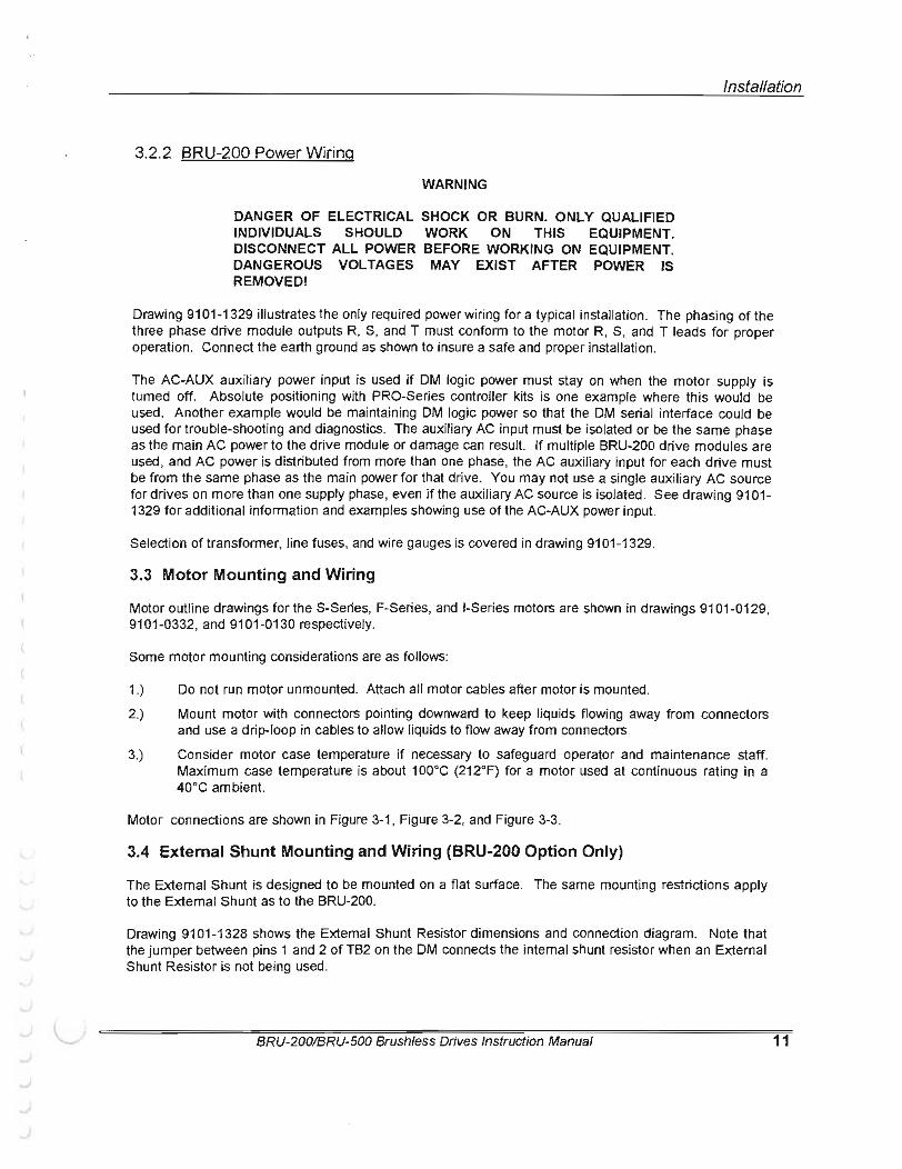
3.2.2 BRU-200 Power Wiring
WARNING
DANGER OF ELECTRICAL SHOCK OR BURN. ONLY QUALIFIED INDIVIDUALS SHOULD WORK ON THIS EQUIPMENT. DISCONNECT ALL POWER BEFORE WORKING ON EQUIPMENT. DANGEROUS VOLTAGES MAY EXIST AFTER POWER IS REMOVED!
Drawing 9101-1329 illustrates the only required power wiring for a typical installation. The phasing of the three phase drive module outputs R, S, and T must conform to the motor R. S, and T leads for proper operation. Connect the earth ground as shown to insure a safe and proper installation.
The AC-AUX auxiliary power input is used if DM logic power must stay on when the motor supply is turned off. Absolute positioning with PRO-Series controller kits is one example where this would be used. Another example would be maintaining DM logic power so that the DM serial interface could be used for trouble-shooting and diagnostics. The auxil iary AC input must be isolated or be the same phase as the main AC power to the drive module or damage can result. If multiple BRU-200 drive modules are used, and AC power is distributed from more than one phase, the AC auxiliary input for each drive must be from the same phase as the main power for that drive. You may not use a single auxiliary AC source for drives on more than one supply phase, even if the auxiliary AC source is isolated. See drawing 9101-1329 for additional information and examples showing use of the AC-AUX power input.
Selection of transformer, line fuses, and wire gauges is covered in drawing 9101-1329.
3.3 Motor Mounting and Wiring
Motor outline drawings for the S-Series, F-Series, and 1-Series motors are shown in drawings 9101-0129, 9101-0332, and 9101-0130 respectively.
Some motor mounting considerations are as follows:
1.) Do not run motor unmounted. Attach all motor cables after motor is mounted.
2.) Mount motor with connectors pointing downward to keep liquids flowing away from connectors and use a drip-loop in cables to allow liquids to flow away from connectors.
3.) Consider motor case temperature if necessary to safeguard operator and maintenance staff. Maximum case temperature is about 1 oooc (212°F) for a motor used at continuous rating in a 40°C ambient.
Motor connections are shown in Figure 3-1 , Figure 3-2, and Figure 3-3.
3.4 External Shunt Mounting and Wiring (BRU-200 Option Only}
The External Shunt is designed to be mounted on a flat surface. The same mounting restrictions apply to the External Shunt as to the BRU-200.
Drawing 9101-1328 shows the External Shunt Resistor dimensions and connection diagram. Note that the jumper between pins 1 and 2 of TB2 on the DM connects the internal shunt resistor when an External Shunt Resistor is not being used.
BRU-200/BRU-500 Brushless Drives Instruction Manual 11
Installation
12
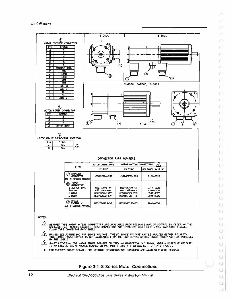
5-2000 5-3000 <D
MOTOR EHCOOER CONECTOR PIH SISHAL
A A+ B A-c 8+ D E I+ F I-6 EHCOOeR CASE H ABS .J +SVDC
" +SVDC l COff If COPt H HALL B
5-4000, 5-6000, 5-8000 p HALL C R rs. s TS-T HALL A
@ HOTOR POWER CtHIECTOR
PIH SISHAL A R B s c T D lfOTOR CASE
® HOT OR BRAKE ctHIECTOR COPTI 010
t-1 &
CONNECTOR PART NUMBERS IIOTOR aHECTORS IIOTOR lfATIHG aHECTORS & ITEH
ffS TYPE ffS TYPE llfl.lAHCE PART HO.
<D a«:ooeR aHECTOR ff531 02R20-29P lf531 06F2C>-29S 9101-o329 All 5-SERIES IIOTORS
@ =CTOR 5-2000, 5-3000 lf53102R18-4P 9101-()325 s-...ooo 11531 02R20-4P lfS3J 06F2C>-4S 9101-()3:26 s-6000 lfS31 02R2.f-22P lfS31 061'2+-225 9J01-c327 5-8000 11531 02R32-17P lfS31 06F32-J 7S 9101-()328
@ =CTOR lfS31 02Rl2S-3P lfS31 06F12S-3S 9J01-o330 All 5-SERIES lfOTORS
NOTES•
& HS3106F TYPE MOTOR HATING CONECTORS ARE AVAILABLE FROH Ra.IANCE HOTION CONTROL BY ORDERING THE RELIANCE PART MJifSER LISTED. THESE CONNECTORS ARE STRAIGHT CABLE EXIT TYPE, AHD HAVE A CABLE ClNIP TYPE CCHECTOR BACK SHELL.
BIW:f, SCE FIGURE 9-2 FOR fiW(f VOLTAGE. THE DC BRAKE VOLTAGE HAY BE APPLIED EITHER POLARITY. CTHE BRAKE POIIER SUPPLY IS NOT AVAILABLE FROH THE BRU-SERIES DRIVE. BRAKE POIIER HUST BE PROVIDED BY THE USER.> SHAFT ROTATION, THE lfOTOR SHAFT ROTATES CIJ VIEWING DIRECTION •A• SHOWN, IIHEN A POSITIVE VOLTAGE IS APPLIED AT DRIVE HODU.E CONNECTOR Pl, PIN 4 CVCS+) WITH RESPECT TO PIH 3 eves->.
4. FOR FURTHER HOTOR OETAil, EH6INEERING SPECIFICATION DRAIJIHSS ARE AVAILABLE UPON REQUEST.
Figure 3-1 S-Series Motor Connections
BRU-200/BRU-500 Brushless Drives Instruction Manual

(
r Installation
CD MOTOR ENCODER CONNECTOR F-SERIES MOTORS
PIN SIGNAl.. A A+ s A-c S+ 0 s- II-E I+ F I-6 ENCODER CASE H ASS -- -------------'-1- -+ J +5VDC K +SVOC L COM M COM N HALLS p HALL C Pb R TS+ s Ts-T HALL A 1 2
® "A" & MOTOR POWER CONNECTOR
PIN SIGNAl.. A R s s c T 0 MOTOR CASE
® MOTOR BRAKE CONNECTOR (OPTION)
I pr I SIGNAl.. I& BR+ 8R-
CONNECTOR PART NUMBERS
MOTOR MOTOR HATING CONIECTORS ill ITEM HS TYPE HS TYPE RELIANCE PART NO.
CD ENCODER CCNIECTOR HS3i02R20-29P MS3106F2o-29S 9101-o329 AI..L F-SERIES MOTORS
@ =CTOR F-4000 IIS3102R20-4P MS3106F20-4S 9101-o326 F-6000 MS3i02R24-22P MS3106F24-22S 910t-o327
@ =CTOR MS3102R125-3P MS3106F12S-3S 9101-0330 A1..L F-SERIES MOTORS
NOTES:
& MS3106F TYPE MOTOR MATING CONNECTORS ARE AVAILABLE FROM RELIANCE MOTION CONTROL BY ORDERING THE RELIANCE PART NUMBER LISTED. Tt£SE CONNECTORS ARE STRAIGHT CABLE EXIT TYPE. AMl HAVE A CABLE CLAMP TYPE CONNECTOR BACK SHELL.
& BRAKE: SEE FIGURE 9-2 FOR BRAKE VOLTAGE. THE DC BRAKE VOLTAGE MAY BE APPLIED EITHER POLARITY. (THE BRAKE POWER SUPPLY IS NOT AVAILABLE FROM THE BRU-SERIES DRIVE. BRAKE POWER MUST BE PROVIDED
& BY 11£ USER.) SHAFT THE MOTOR SHAFT ROTATES CW VIEWING DIRECTION "A" SHOWN. NHEN A POSITIVE VOLTAGE IS APPLIED AT DRIVE MODULE CONNECTOR Pi. PIN 4 (VCS+) WITH RESPECT TO PIN 3 (VCS-) .
4. FOR FURTHER MOTOR ENGINEERING SPECIFICATION DRAWINGS ARE AVAILABLE UPON REQUEST.
Figure 3·2 F-Series Motor Connections
BRU-200/BRU-500 Brushless Drives Instruction Manual 13

Installation
14
<D MOTOR ENCODER CONNECTOR
PDI SISNAL 1 +5VDC 2 COM 3 B+ 4 8-5 A-6 A+ 7 I+ 8 I-9 6AOIHl 10 -11 -12 -13 -14 -15 TS+ 16 Ts-
® I«>TOR POWER TERMINAL STRIP
TaiiDW.. SISNAL u s v A II T E I«>TOR CASE
® FAN POWER TERMINAL STRIP
TEIIIIIW.. 81 82 BE
SI6NAL FAN POIIEA
MOTOR CASE
M5 TKIEAD FOR I -5300 ll/12.51a MAX LUG DIA 116 TKIEAD FOR I-6600 11/ 17• MAX LU6 DIA
I-5300, I-6600 MOTORS
"A"
TERMINAL BOX LAYOUT (TOP VIEW)
(D ENCODER CONNECTOR PART NUMBERS
MOTOR EHCOOER CONIECTOR !MoTOR ENCOilE.JI 11A TINS COllECTOR .& COI*ECTOR TYPE COllECTOR TYPE AEI.IANCE PART NO . MIP 1-480439-0 AJif' 1-480438-0
COI*ECTOR IIIlli SOCKET CCNECTOR ANl AJif' 9101-G331 CONTACTS 60617-5 CRill' PIN
CONTACTS
NOTES:
1 1/2 INCH ,..,-
THE MOTOR ENCODER MATING CONNECTOR (INCLUDING CRIMP PIN CONTACTS) IS PROVIDED IIITH THE MOTOR.
& FAN POWER REQUIREMENT: 230 VAC RMS. 50/ 60 HZ. 1.0/ 0 . 85 AMPS AC RMS. (THE FAN POWER SUPPLY IS NOT AVAILABLE FROM THE DRIVE. FAN POWER MUST BE PROVIDED BY THE US£R. )
& SHAFT ROTATION: THE MOTOR SHAFT ROTATES CW VIEWING DIRECTION "A" SHOIIN, FOR A POSITIVE COMMAND .
4 . FOR FURTHER MOTOR DETAIL ENGINEERING SPECIFICATION DRAWINGS ARE AVAILABLE UPON REQUEST.
Figure 3-3 1-Series Motor Connections
BRU-200/BRU-500 Brushless Drives Instruction Manual
(

(
r
(
Interface Circuitry
SECTION IV • INTERFACE CIRCUITRY
Pin #1 of the interface connectors is indicated on both modules by a white dot on the module covers.
4.1 Drive Module Interface Connectors
Connector Signal Name
P6 (Serial) ............................................... 7 ................................. + 5 VDC 6 ................................. Shield 5 ................................. RCV-4 ................................. RCV+ (RS-422 Only) 3 ................................. Common 2 ................................ J<MT + (RS-422 Only) 1 ................................. XMT-
P5 (Monitor) ............................. ............... 8 ................................. - 15 VDC (Not for external use) ? ................................. + 15 VDC (Not for external use) 6 ................................. Shield 5 ................................. Common 4 ................................. External Current Umit Input 3 ................................. Programmable Monitor Output 2 ................................. MVO (Motor Velocity Output) 1 ................................. MCO (Motor Current Output)
P4 (Encoder In) ...................................... 14 ............................... TS- (Motor thermal switch) 13 ............................... TS+ (Motor thermal switch) 12 ............................... Common 11 ............................... +5 VDC 10 ............................... Shield 9 ................................. A8S (Absolute Encoder) 8 ................................. 1-7 ................................. 1+ 6 ................................. 8-5 ................................. 8+ 4 ................................. A-3 ............ ..................... A+ 2 ................................. Common 1 ................................. +5 VDC
P3 (Encoder Out) .................................. 7 ................................. Shield 6 ................................. 1-5 ................................. 1+ 4 ................................. 8 -3 ................................. 8+ 2 ........ ......................... A -1 ................................. A +
BRU-200/BRU-500 Brushless Drives Instruction Manual 15
Interface Circuitry
16
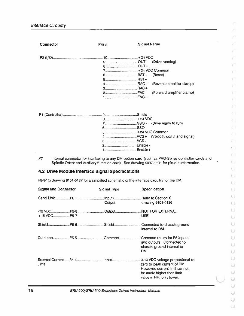
Connector Signal Name
P2 (1/ 0) ................................................... 10 ............................... +24 VDC 9 ................................. 0UT- (Drive running) S ................................. OUT+ 7 ................................. +24 VDC Common 6 ................................. RST - (Reset) 5 ................................. RST + 4 ................................. RAC - (Reverse amplifier clamp) 3 ................................. RAC+ 2 ........................... ...... FAC- (Forward amplifier clamp) 1 ................................. FAC+
P1 (Controller) ........................................ 9 ................................. Shield 8 ................................. +24 VDC 7 ................................. SSO- (Drive ready to run) 6 ................................. SSO+ 5 ................................. + 24 VDC Common 4 ................................. VCS + (Velocity command signal) 3 ................................. vcs-2 ................................. Enable -1 ................................. Enable+
.P7 Internal connector for interfacing to any OM option card (such as PRO-Series controller cards and Spindle Orient and Auxiliary Function card). See drawing 9097-1131 for pin-out information.
4.2 Drive Module Interface Signal Specifications
Refer to drawing 9101-0137 for a simplified schematic of the interface circuitry for the OM.
Signal and Connector SignaiTvpe Specification
Serial Unk ............... P6 .............................. 1 nputj ........................... Refer to Section X Output drawing 9101-0136
-15 VDC ................... P5-8 ........................... 0utput .......................... NOT FOR EXTERNAL +15 VDC ................. P5-7 USE
Shield ...................... P5-6 ........................... Shield ........................... Connected to chassis ground internal to OM.
Common ................. P5-5 ........................... Common ...................... Common retum for P5 inputs and outputs. Connected to chassis ground internal to OM.
External Current ..... P5-4 ........................... Input ............................. 0-10 VDC voltage proportional to Umit zero to peak current of OM.
However, current limit cannot be made higher than limit value in PM, only lower.
BRU-200/BRU-500 Brushless Drives Instruction Manual
(
r ( Interface Circuitry
Signal and Connector Signal Type Specification
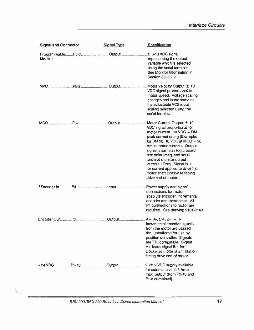
Programmable ........ P5-3 ........................... Output ......... ................. ± 0-10 VDC signal Monitor representing the output
variable which is selected using the serial terminal. See Monitor Information in Section 5.2.3.2.2.
MVO ........................ P5-2 ........................... Output .......................... Motor Velocity Output: ± 1 0 VDC signal proportional to motor speed. Voltage scaling changes and is the same as the adjustable VCS input scaling selected using the serial terminal.
MCO ........................ P5-1 ........................... Output .......................... Motor Current Output: ± 10 VDC signal proportional to motor current. 10 VDC = OM peak current rating (Example: for OM 20, 10 VDC at MCO = 20 Amps motor current). Output signal is same as logic board test point lmag, and serial terminal monitor output variable I Torq. Signal is+ for current applied to drive the motor shaft clockwise facing drive end of motor.
*Enccx:Jer In ............ P4 .............................. Input ............................. Power supply and signal connections for motor absolute enccx:Jer, incremental enccx:Jer and thermostat. All P4 connections to motor are required. See drawing 9101.0140.
Encoder Out ........... P3 .............................. 0utput .......................... A+ , A-, 8+, 8-, 1+, !-incremental enccx:Jer signals from the motor are passed thru unbuffered for use by position controller. Signals are TIL compatible. Signal A+ leads signal 8 + for clockwise motor shaft rotation facing drive end of motor.
+ 24 VDC ................. P2-1 0 ......................... Output .......................... 26 ± 2 VDC supply available for external use. 0.5 Amp max. output (from P2-1 0 and P1-8 combined).
BRU-200/BRU-500 Brushless Drives Instruction Manual 17

Interface Circuitry
18
Signal and Connector Signal Type Specification
OUT+ ...................... P2-8 ........................... Output .......................... Normally open relay contacts OUT- ....................... P2-9 that close when the OM is
enabled at input pins P1 -1, P1-2. The relay opens when the OM is inhibited. Contact rating is 0.3 Amps maximum at 24VDC.
+24 VDC Com ........ P2-7 ........................... Common ...................... Common return for +24 VDC supply. + 24 VDC Com is floating and not connected to chassis ground internal to OM. May be connected to chassis ground of external equipment.
RST + ...................... P2-5 ........................... Input ............................. Reset: Momentarily connecting RST- ........................ P2-6 and then disconnecting these pins
resets any OM fault indications.
*RAC-...................... P2-4 ........................... Input ............................. Reverse Amplifier Clamp: *RAC+ .................... P2-3 Connecting these pins allows
motion in the reverse direction (CCW motor shaft rotation facing drive end of motor).
*FAC-...................... P2-2 ........................... Input ............................. Forward Amplifier Clamp: *FAC+ .................... P2-1 Connecting these pins allows
motion in the forward direction (CW motor shaft rotation facing drive end of motor).
Shield ...................... P1-9 ........................... Shield ........................... Connected to chassis ground internal to OM.
+ 24VOC .................. P1-8 ........................... Output .......................... 26 ± 2 VOC supply available for external use. 0.5 Amp max. output (from P2-1 0 and P1-8 combined).
SSO + ..... ................. P1-6 ........................... Output .......................... Normally open relay that SSO- ....................... P1-7 closes when the OM is ready to run.
The relay opens if there is a OM fault. Contact rating is 0.3 Amps maximum at 24 VDC.
BRU-200/BRU-500 Brushless Drives Instruction Manual
(
r Interface Circuitry
Signal and Connector Signal Tyee Specification
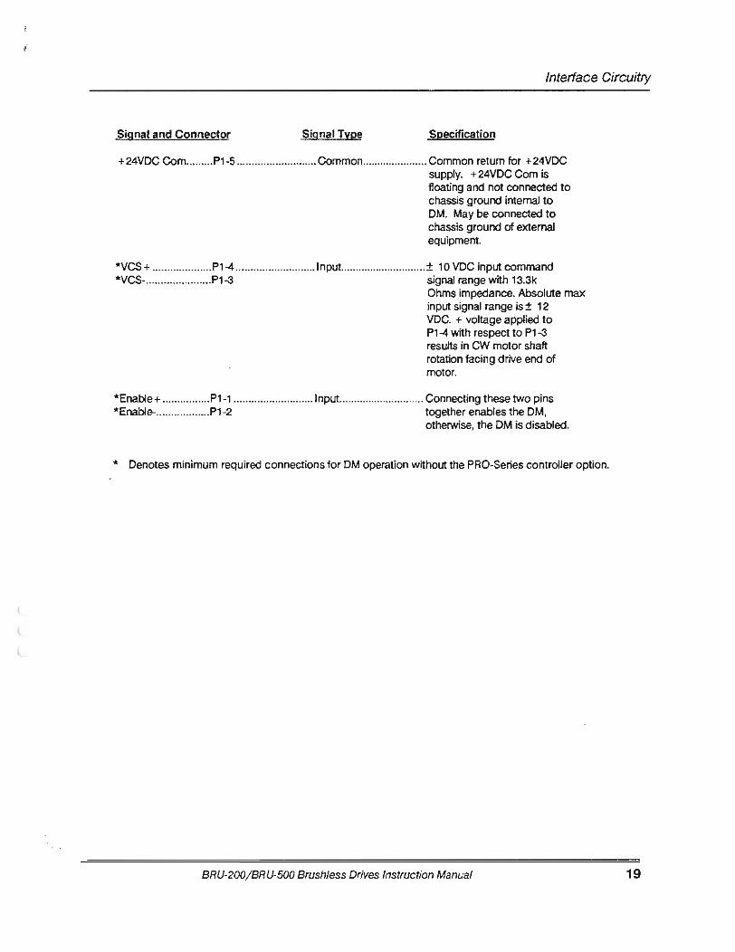
+ 24VDC Com ......... P1-5 ........................... Common ...................... Common return for + 24VDC supply. + 24VDC Com is floating and not connected to chassis ground internal to OM. May be connected to chassis ground of external equipment.
*VCS+ .................... P1-4 ........................... 1nput ............................ ± 10 VDC input command *VCS-...................... P1-3 signal range with 13.3k
Ohms impedance. Absolute max input signal range is± 12 VDC. + voltage applied to P1-4 with respect to P1-3 results in CW motor shaft rotation facing drive end of motor.
*Enable+ ................ P1-1 ........................... Input ............................. Connecting these two pins *Enable-.................. P1 -2 together enables the OM,
otherwise, the OM is disabled.
* Denotes minimum required connections for OM operation without the PRO-Series controller option.
BRU-200/ BRU-500 Brushless Drives Instruction Manual 19

Interface Circuitry
20
4.3 Power Supply Module Interface Connector (BRU-500 Only)
Connector Signal Name
P1 1 ................................. Status-2 ................................. Status+ 3 ................................. PSM Enable-4 ................................. PSM Enable+
4.4 Power Supply Module Interface Signal Specifications (BRU-500 Only)
Refer to drawing 9101-Q138 for simplified schematic of interface circuitry.
Signal and Connector Signal Type Specification
Status+ ................... Pl-2 ........................... Output .......................... -Normally open relay Status-..................... Pl -1 -24 VDC 0.4 A
-open relay is PSM fault -closed relay is PSM OK
Enable+ .................. P1-4 .. ......................... 1nput[1] ........................ -Opto-coupler input Enable-.................... Pl-3 -1 .5k Ohms
-16 rnA (± 6mA) tum-on current
[1] The PSM Enable input is only functional if jumper W1 is in the proper location (see Figure 5.1).
With the jumper in the enable input activated position, the PSM is enabled if the opto-coupler is turned on. Wrth the opto-coupler off, the PSM DC bus is turned off and the dissipative shunt is turned on to quick discharge the DC bus capacitors and dynamically brake synchronous motors. IF THE PSM IS DISABLED DURING A POWER-UP, THE DC BUS VOLTAGE WILL BE PRESENT FOR AT LEAST 2 SECONDS BEFORE RETURNING TO A ZERO VOLT CONDITION. This is to allow time for the OMs to power-up and apply the enable signal to the PSM if the PSM is to remain on.
With the jumper in the enable input deactivated position, the enable input has no effect on the PSM operation and the PSM activates itself when three phase voltage in the proper voltage range is connected to the input. Jumper W1 is in the enable input deactivated position when shipped from Reliance Motion Control.
BRU-200/BRU-500 Brushless Drives Instruction Manual
(
r
(
Start-Up and Adjustments
SECTION V- START-UP AND ADJUSTMENTS
5.1 Initial Start-Up Procedure 5.1.1 Initial Start-Up Procedure (BRU-500)
WARNING
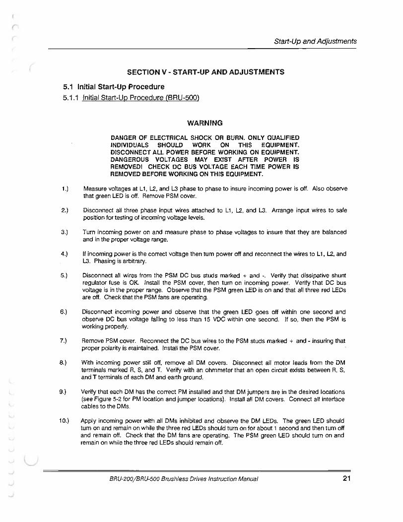
DANGER OF ELECTRICAL SHOCK OR BURN. ONLY QUAUFIED INDIVIDUALS SHOULD WORK ON THIS EQUIPMENT. DISCONNECT All POWER BEFORE WORKING ON EQUIPMENT. DANGEROUS VOLTAGES MAY EXIST AFTER POWER IS REMOVED! CHECK DC BUS VOLTAGE EACH TIME POWER IS REMOVED BEFORE WORKING ON THIS EQUIPMENT.
1.) Measure voltages at L1, l2, and L3 phase to phase to insure incoming power is off. Also observe that green LED is off. Remove PSM cover.
2.) Disconnect all three phase input wires attached to L 1, l2, and L3. Arrange input wires to safe position for testing of incoming voltage levels.
3.) Tum incoming power on and measure phase to phase voltages to insure that they are balanced and in the proper voltage range.
4.) If incoming power is the correct voltage then turn power off and reconnect the wires to L 1, l2, and L3. Phasing is arbitrary.
5.) Disconnect all wires from the PSM DC bus studs marked + and -. Verify that dissipative shunt regulator fuse is OK. Install the PSM cover, then turn on incoming power. Verify that DC bus voltage is in the proper range. Observe that the PSM green LED is on and that all three red LEOs are off. Check that the PSM fans are operating.
6.) Disconnect incoming power and observe that the green LED goes off within one second and observe DC bus voltage falling to less than 15 VDC within one second. If so, then the PSM is working properly.
7.) Remove PSM cover. Reconnect the DC bus wires to the PSM studs marked + and - insuring that proper polarity is maintained. Install the PSM cover.
8.) With incoming power still off, remove all DM covers. Disconnect all motor leads from the OM terminals marked R, S, and T. Verify with an ohmmeter that an open circuit exists between R, S, and T terminals of each OM and earth ground.
9.) Verify that each OM has the correct PM installed and that OM jumpers are in the desired locations (see Figure 5-2 for PM location and jumper locations). Install all OM covers. Connect all interface cables to the OMs.
1 0.) Apply incoming power with all OMs inhibited and observe the OM LEOs. The green LED should tum on and remain on while the three red LEOs should turn on for about 1 second and then tum off and remain off. Check that the OM fans are operating. The PSM green LED should turn on and remain on while the three red LEOs should remain off.
BRU-200/ BRU-500 Brushless Drives Instruction Manual 21
Start-Up and Adjustments
22
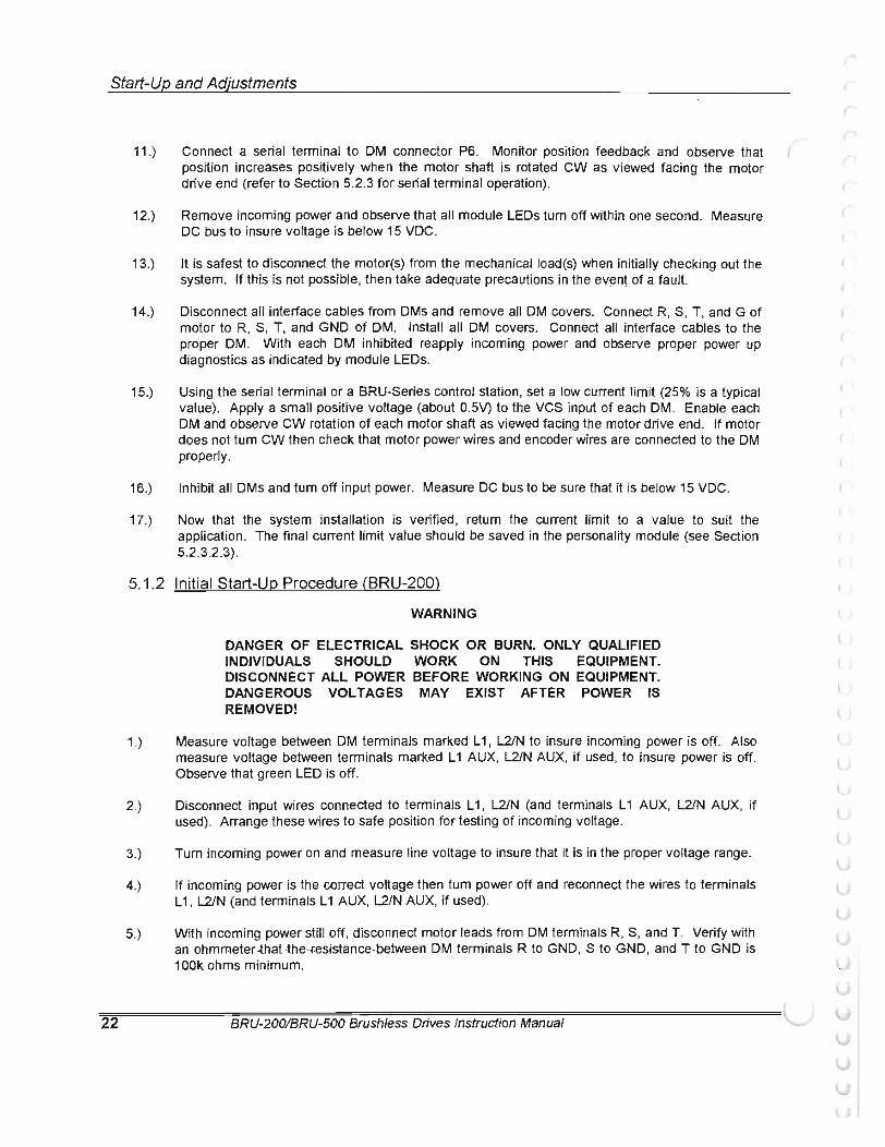
11 .) Connect a serial terminal to DM connector P6. Monitor position feedback and observe that position increases positively when the motor shaft is rotated CW as viewed facing the motor drive end (refer to Section 5.2.3 for serial terminal operation).
12.) Remove incoming power and observe that all module LEDs tum off within one second. Measure DC bus to insure voltage is below 15 VDC.
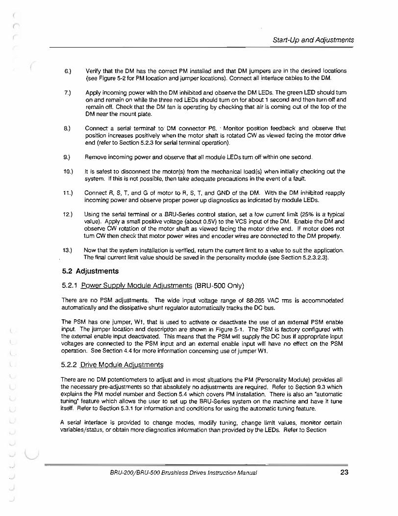
13.) It is safest to disconnect the motor(s) from the mechanical load(s) when initially checking out the system. If this is not possible, then take adequate precautions in the event of a fault.
14.) Disconnect all interface cables from DMs and remove all DM covers. Connect R, S, T, and G of motor to R, S, T, and GND of DM. Install all DM covers. Connect all interface cables to the proper DM. With each DM inhibited reapply incoming power and observe proper power up diagnostics as indicated by module LEDs.
15.) Using the serial terminal or a BRU-Series control station, set a low current limit (25% is a typical value). Apply a small positive voltage (about 0.5V) to the VCS input of each DM. Enable each DM and observe CW rotation of each motor shaft as viewed facing the motor drive end. If motor does not tum CW then check that motor power wires and encoder wires are connected to the DM properly.
16.) Inhibit all DMs and tum off input power. Measure DC bus to be sure that it is below 15 VDC.
17 .) Now that the system installation is verified, return the current limit to a value to suit the application. The final current limit value should be saved in the personality module (see Section 5.2.3.2.3) .
5.1.2 Initial Start-Up Procedure (BRU-200)
WARNING
1.)
2.)
3.)
4.)
5.)
DANGER OF ELECTRICAL SHOCK OR BURN. ONLY QUALIFIED INDIVIDUALS SHOULD WORK ON THIS EQUIPMENT. DISCONNECT ALL POWER BEFORE WORKING ON EQUIPMENT. DANGEROUS VOLTAGES MAY EXIST AFTER POWER IS REMOVED!
Measure voltage between DM terminals marked L 1, L2/N to insure incoming power is off. Also measure voltage between terminals marked L 1 AUX, L2/N AUX, if used, to insure power is off. Observe that green LED is off.
Disconnect input wires connected to terminals L 1, L2/N (and terminals L 1 AUX, L2/N AUX, if used). Arrange these wires to sate position for testing of incoming voltage.
Turn incoming power on and measure line voltage to insure that it is in the proper voltage range.
If incoming power is the correct voltage then tum power off and reconnect the wires to terminals L 1, L2/N (and terminals L 1 AUX, L2/N AUX, if used).
With incoming power still off, disconnect motor leads from DM terminals R, S, and T. Verify with an ohmmeter .that ·the f.esistance .between DM terminals R to GND, S to GND, and T to GND is 1 OOk ohms minimum.
BRU-200/BRU-500 Brush/ess Drives Instruction Manual
(
r (
(
Start-Up and Adjustments
6.) Verify that the OM has the correct PM installed and that OM jumpers are in the desired locations (see Figure 5-2 for PM location and jumper locations). Connect all interface cables to the OM.
7.) Apply incoming power with the OM inhibited and observe the OM LEOs. The green LED should tum on and remain on while the three red LEOs should tum on for about 1 second and then tum off and remain off. Check that the OM fan is operating by checking that air is coming out of the top of the OM near the mount plate.
8.) Connect a serial· terminat to· OM connector· P6. ··Monitor position feedback and observe that position increases positively when the motor shaft is rotated CW as viewed facing the motor drive end (refer to Section 5.2.3 for serial terminal operation).
9.) Remove incoming power and observe that all module LEOs tum off within one second.
10.) It is safest to disconnect the motor(s) from the mechanicalload(s) when initially checking out the system. If this is not possible, then take adequate precautions in the event of a fault.
11.) Connect R, S, T, and G of motor to R, S, T, and GND of the OM. With the OM inhibited reapply incoming power and observe proper power up diagnostics as indicated by module LEOs.
12.) Using the serial terminal or a BRU-Series control station, set a low current limit (25% is a typical value). Apply a small positive voltage (about 0.5V) to the VCS input of the OM. Enable the OM and observe CW rotation of the motor shaft as viewed facing the motor drive end. If motor does not tum CW then check that motor power wires and encoder wires are connected to the OM proper1y.
13.) Now that the system installation is verified, return the current limit to a value to suit the application. The final current limit value should be saved in the personality module (see Section 5.2.3.2.3).
5.2 Adjustments
5.2.1 Power Supply Module Adjustments (BRU-500 Only)
There are no PSM adjustments. The wide input voltage range of 88-265 VAC rms is accommodated automatically and the dissipative shunt regulator automatically tracks the DC bus.
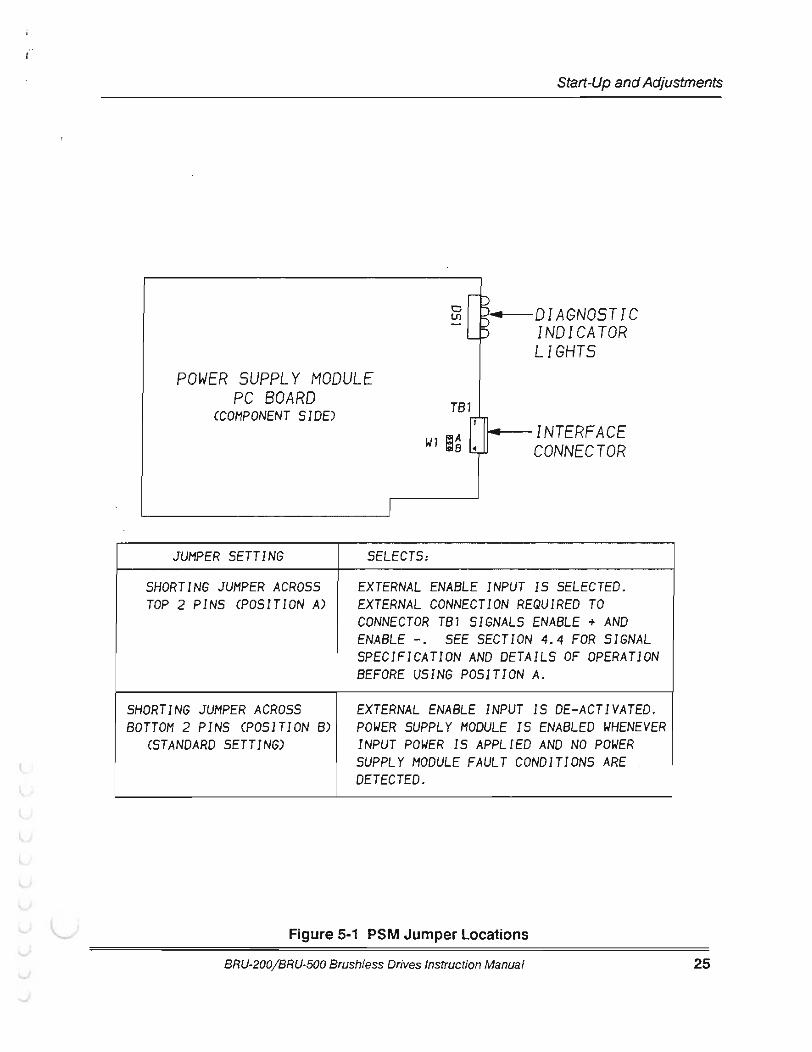
The PSM has one jumper, W1, that is used to activate or deactivate the use of an external PSM enable input. The jumper location and description are shown in Figure 5-1. The PSM is factory configured with the external enable input deactivated. This means that the PSM will supply the DC bus if appropriate input voltages are connected to the PSM input and an external enable input will have no effect on the PSM operation. See Section 4.4 for more information concerning use of jumper W1.
5.2.2 Drive Module Adjustments
There are no OM potentiometers to adjust and in most situations the PM (Personality Module) provides all the necessary pre-adjustments so that absolutely no adjustments are required. Refer to Section 9.3 which explains the PM model number and Section 5.4 which covers PM installation. There is also an "automatic tuning" feature which allows the user to set up the BRU-Series system on the machine and have it tune itself. Refer to Section 5.3.1 for information and conditions for using the automatic tuning feature.
A serial interface is provided to change modes, modify tuning, change limit values. monitor certain variablesj status, or obtain more diagnostics information than provided by the LEOs. Refer to Section
BRU-200/ BRU-500 Brushless Drives Instruction Manual 23

Start-Up and Adjustments
24
5.2.3 for information on using the serial interface. Refer to Section 5.3 for information on tuning the servo drive. ·
The wide input voltage range of 125-375 VDC for the BRU-500 and 100-240 VAC for the BRU-200 is adjusted for automatically and the dissipative shunt regulator automatically tracks the internal DC bus.
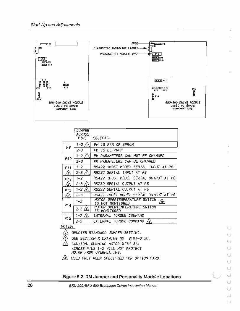
The OM has several jumpers that are shown and described in Figure 5-2. Factory installed locations are indicated. The location of the PM is also indicated.
BRU-200/BRU-500 Brushless Drives Instruction Manual
(
l
(
r
(
Start-Up and Adjustments
0 4 DIAGNOSTIC U1
INDICATOR LIGHTS
POWER SUPPLY MODULE PC BOARD TB1 (COMPONENT SIDE)
w1 . INTERFACE CONNECTOR
JUMPER SETTING SELECTS:
SHORTING JUMPER ACROSS EXTERNAL ENABLE INPUT IS SELECTED. TOP 2 PINS CPOSITION A) EXTERNAL CONNECTION REQUIRED TO
CONNECTOR TB1 SIGNALS ENABLE + AND ENABLE -. SEE SECTION 4.4 FOR SIGNAL SPECIFICATION AND DETAILS OF OPERATION BEFORE USING POSITION A.
SHORTING JUMPER ACROSS EXTERNAL ENABLE INPUT IS DE-ACTIVATED. BOTTOM 2 PINS (POSITION B) POWER SUPPLY MODULE IS ENABLED WHENEVER
CST ANDARD SETTING) INPUT POWER IS APPLIED AND NO POWER SUPPLY MODULE FAULT CONDITIONS ARE DETECTED.
Figure 5-1 PSM Jumper Locations
BRU-200/BRU-500 Brushless Drives Instruction Manual 25
Start-Up and Adjustments
26
c::::IJFl 'L------J' [r IEDIP9 IEDIPlO
Pl3 e e e Pll Pl2
I lED PIS
FUSE DIAGNOSTIC JI'()JCATOR LIGHTS-. U_
PERSONALITY HOOULE CPif)
Pl2 Pl3
a PH
PIS
s, BRu-200 DRIVE HODULE
LOGIC PC BOARD CCCli'IPOHENT SlllEl
BRu-SOo DRIVE MODULE LOGIC PC BOARD
CCt1I'I>OHEKT SlOEJ
JUMPER ACROSS PINS SELECTS:
pg 1-2& PH IS RAM OR EPROM 2-3 PH IS EE PROM 1-2& PH PARAMETERS CAN NOT BE CHANGED P10 2-3 PH PARAMETERS CAN BE CHANGED
&: 1-2 RS422 CHOST MODE) SERIAL INPUT AT P6 2-3& RS232 SERIAL INPUT AT P6 1-2 RS422 CHOST MODE) SERIAL OUTPUT AT P6 2-3& RS232 SERIAL OUTPUT AT P6 1-2& RS232 SERIAL OUTPUT AT P6 2-3 RS422 CHOST MODE) SERIAL OUTPUT AT P6 1-2 MOTOR OVERTEHPERATURE SWITCH
IS NOT MONITORED 3 P14 2-3& MOTOR OVERTEHPERATURE SWITCH
IS MONITORED 1-2& INTERNAL TORQUE COMMAND P1S 2-3 EXTERNAL TORQUE COMMAND
NOTES: DENOTES STANDARD JUMPER SETTING.
£ SEE SECTION X DRAWING NO. 9101-0136. CAUTION: RUNNING MOTOR WITH J14 ACROSS PINS 1-2 WILL NOT PROTECT MOTOR FROM OVERHEATING. USED ONLY WHEN SPECIFIED FOR OPTION CARD.
Figure 5-2 DM Jumper and Personality Module Locations
BRU-200/BRU-500 Brushless Drives Instruction Manual
l
(
r r
( 5.2.3 Serial Interface Operation
5.2.3.1 User Terminal Requirements
Start-Up and Adjustments
The BRU-Series serial interface is factory configured for RS-232 compatibility, but RS-422 operation is possible by making jumper changes. Refer to Figure 5-2 for jumper locations and configurations. The BRU-Series serial interface is designed to work with the Tandy 1 02 computer, but should interface to VT -52 compatible terminals with at ieast ·an ·eight ·line 40 character display. The terminal should be set for full duplex, 8 bit words, no parity, 1 stop bit, with XON/ XOFF (software handshake) enabled. Refer to drawing 9101-0136 for serial interface connection details. Appendix A is a step-by-step guide on how to set up the Tandy 102 for operation with the BRU-Series drive. Appendix B contains the communication codes sent to and received from the BRU-Series drive and the user terminal. Appendix C is a step-by-step guide on using an IBM PC terminal and Appendix 0 covers common communication problems and possible cures.
The default baud rate is stored in the PM (personality module) and is set by the factory to 9600 baud. An autobaud function has been included in the BAU-Series drive to allow terminals with 1200, 2400, 4800, 9600, or 19200 baud to communicate by over-riding the default value. The autobaud function, however, only works during the first second after power is applied, after which the baud rate is set to the default value as stored in the PM. To use the autobaud function, after power is applied and the red LEOs on the drive module tum on, press <Enter> immediately. The Help page should then be displayed on the user terminal as shown in Figure 5-3. The default baud rate may be changed to the baud rate calculated during the autobaud function by turning to the status page by pressing <ESC> and then pressing <S> to save parameters (refer to Section 5.2.3.2.3).
5.2.3.2 Operating the User Terminal
The BRU-Series drive communicates information to the user through 3 pages. The Help Page provides useful information to get the first time user started and shows software release and personality module information. The Status Page indicates the status of the BRU-Series drive, and the Setup Page allows the user to change the tuning parameters for optimal performance. There are four modes of operation: velocity, torque, tune and auto-tune mode. Each of these modes has a Status and Setup page.
5.2.3.2.1 Help Page
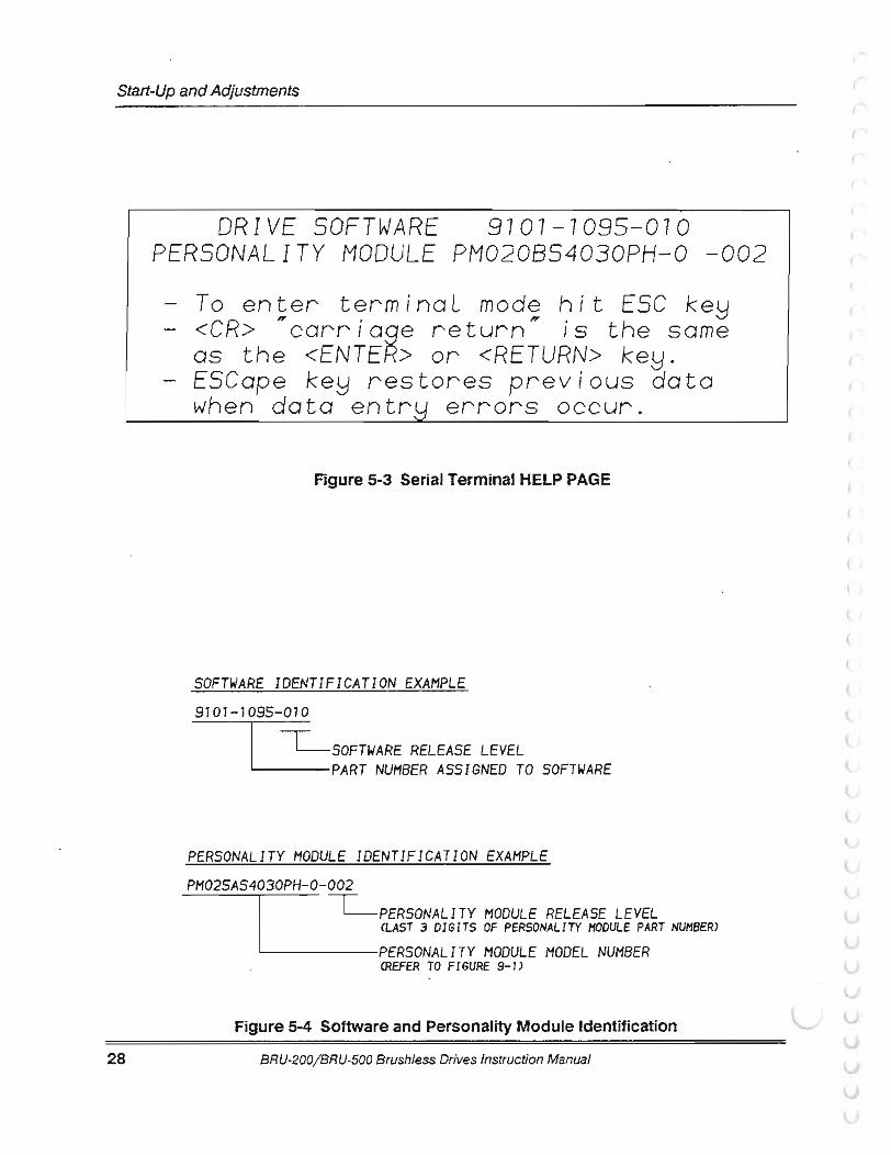
If the user terminal is plugged into OM connector P6 when power is applied to the BRU-Series drive, a help message will appear on the terminal screen when power up diagnostics and autobaud have been completed (see Figure 5.3). The Help page shows the software part number (91 01- 095-XXX, where XXX refers to the software release number), the personality module identification, and a brief description of how to use the terminal. If the power up diagnostic tests fail, the BRU-Series drive automatically turns to the STATUS page which d isplays a description of the error (refer to Section 5.2.3.2.2).
From the Help page, you can press the <ESC> key to enter the Status page or press the < P > key to tum to the Setup page. After pressing the <ESC> or < P > key to tum to the Status or Setup page, you will not be able to return to the Help Page except by resetting the BRU-Series drive through the external reset or by cycling power.
BRU-200/ BRU-500 Brushless Drives Instruction Manual 27
Start-Up and Adjustments
28
DRIVE 9707-7095-070 PERSONALITY MODULE PM020854030PH-0 -002
To enter terminaL mode hit ESC <CR> "carriage return" is the same as the <ENTER> or <RETURN> ESCape restores previous data when data errors occur.
Figure 5-3 Serial Terminal HELP PAGE
SOFTWARE IDENTIFICATION EXAMPLE 9107-7095-010
I --c=__SOFTWARE RELEASE LEVEL PART NUMBER ASSIGNED TO SOFTWARE
PERSONALITY MODULE IDENTIFICATION EXAMPLE PH025AS4030PH-0-002
I --c=__PERSONALITY MODULE RELEASE LEVEL
CLAST 3 DIGITS OF PERSONALITY MODULE PART NUMBER)
L-. -----PERSONALITY MODULE HODEL NUMBER CREFER TO FIGURE 9-1)
Figure 5-4 Software and Personality Module Identification
BRU-200/BRU-500 Brushless Drives Instruction Manual
(
(
(
(
Start-Up and Adjustments
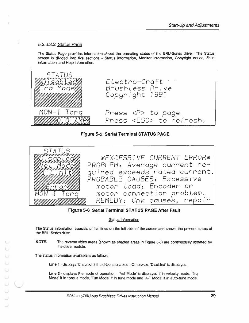
5.2.3.2.2 Status Page
The Status Page provides information about the operating status of the BRU-Series drive. The Status screen is divided into five sections - Status information, Monitor information, Copyright notice, Fault information, and Help information.
MON-I Torq
ELectro-Craft BrushLess Drive Cop!Jright 7997
Press <P> to page Press <ESC> to refresh.
Figure 5-5 Serial Terminal STATUS PAGE
*EXCESSIVE CURRENT ERROR* PROBLEM: Average current quired exceeds rated current. PROBABLE CAUSES: Excessive
motor Load; Encoder or motor connection probLem. REMEDY: Chk causes, repair
Figure 5-6 Serial Terminal STATUS PAGE After Fault
Status Information
The Status information consists of five lines on the left side of the screen and shows the present status of the BRU-Series drive.
NOTE: The reverse video areas (shown as shaded areas in Figure 5-5) are continuously updated by the drive module.
The status information available is as follows:
Une 1 -displays 'Enabled ' if the drive is enabled. Otherwise, 'Disabled' is displayed.
Une 2 - displays the mode of operation. 'Vel Mode' is displayed if in velocity mode, 'Trq Mode' if in torque mode, 'Tun Mode' if in tune mode and 'A-T Mode' if in auto-tune mode.
BRU-200/ BRU-500 Brushless Drives Instruction Manual 29
Start-Up and Adjustments
30
Line 3 - displays current limit status. The BRU-Series drive has been designed to display the 'I Limit' message whenever the drive enters current limit.
Une 4 - displays 'FAC' and 'RAC' clamp status. FAC is the forward amplifier clamp and RAC is the reverse amplifier clamp. When FAC is enabled (displayed on the screen) the VCS input is clamped internally to 0 when a positive voltage on VCS is detected. This allows only negative velocity commands in velocity mode or only negative torque commands in torque mode. The opposite effect occurs with RAC. When both FAC and RAC are enabled, velocity command is clamped to a in-velocity mooe or·torque command is clamped to 0 in torque mode. Both 'FAC' and 'RAC' can be displayed simultaneously. Une 5 -displays the 'Error' message when an error has been detected.
Monitor Information
The monitor information helps in setup and provides a powerful diagnostics tool. The monitor information is selected on the Setup page by changing the monitor variable and is displayed on two lines in the lower left comer of the Status page. The upper line shows the variable which is being monitored and the bottom line shows the value of that variable. The monitor selected on the Setup page is also represented by an analog voltage at the programmable monitor test point or at the monitor output The variables which can be monitored are:
ABS ltorq - Displays the absolute value of commanded torque producing current in units of AMPS.
I Torq - Displays the commanded torque producing current in units of AMPS. Note that I Torq is the same as I mag for the S-Series and F-Series motors.
I Ave- Displays the average value of I Torq in units of AMPS. I Ave prevents the drive from exceeding the current rating. The average value is computed by passing I Torq through a low pass filter. The time constant of the filter is factory set in the personality module. When the average current reaches the rated current of the motor, an excessive current fault will occur.
Tach - Displays the velocity of the motor as determined from the encoder feedback in units of RPM. For forward motion, the velocity will be positive and for reverse motion, the velocity will be negative.
Command - Displays the value of the VCS command input in units of RPM for velocity mode and AMPS for torque mode. In the tune modes, command will be 0, since the command is internally generated.
Posn - Displays the relative motor position in units of ROT or rotations. Posn value will increase for clockwise rotation of the motor shaft, viewed facing the motor drive end. It will decrease for counter-clockwise rotation. For one complete rotation of the motor shaft, the display should indicate a change of one rotation. Note that the display does not show negative rotations, but will change from 0.0 to some large positive number. This occurs due to rollover of the position counter, but after this occurs. continuing to rotate the motor counter-clockwise will cause Posn to decrease. I Limit - Displays the present value of the current limit. The current limit will be set at either the personality current limit (shown on the Setup page) or the external current limit (available at connector PS-4). The current limit is set to the lower of the two values.
BRU-200/BRU-500 Brushless Drives Instruction Manual
(
r ( Start-Up and Adjustments
Copyright Notice
At the upper right area of the Status page is the copyright notice. If an error occurs, the copyright notice is replaced with the fault information described below.
Fault Information While the BRU-Series drive is powering up, diagnostic checks are run to check for proper operation of the drive. Also, while the BRU-Series drive is operating, the drive is monitored for fault conditions. If a fault occurs at either time; then the drive is disabled; the red LEOs display the fault code, and a fault message is displayed in the upper right side of the Status page. The fault message includes a description of the fault, some probable causes for the fault, and some possible remedies. Refer to Section 6.3 for a list of the fault messages.
Help Information
At the lower right area of the Status page are two lines which list available keys while in the Status page. They are as follows:
< P > - page command. Turn to Setup page.
<ESC> -refresh the Status Screen.
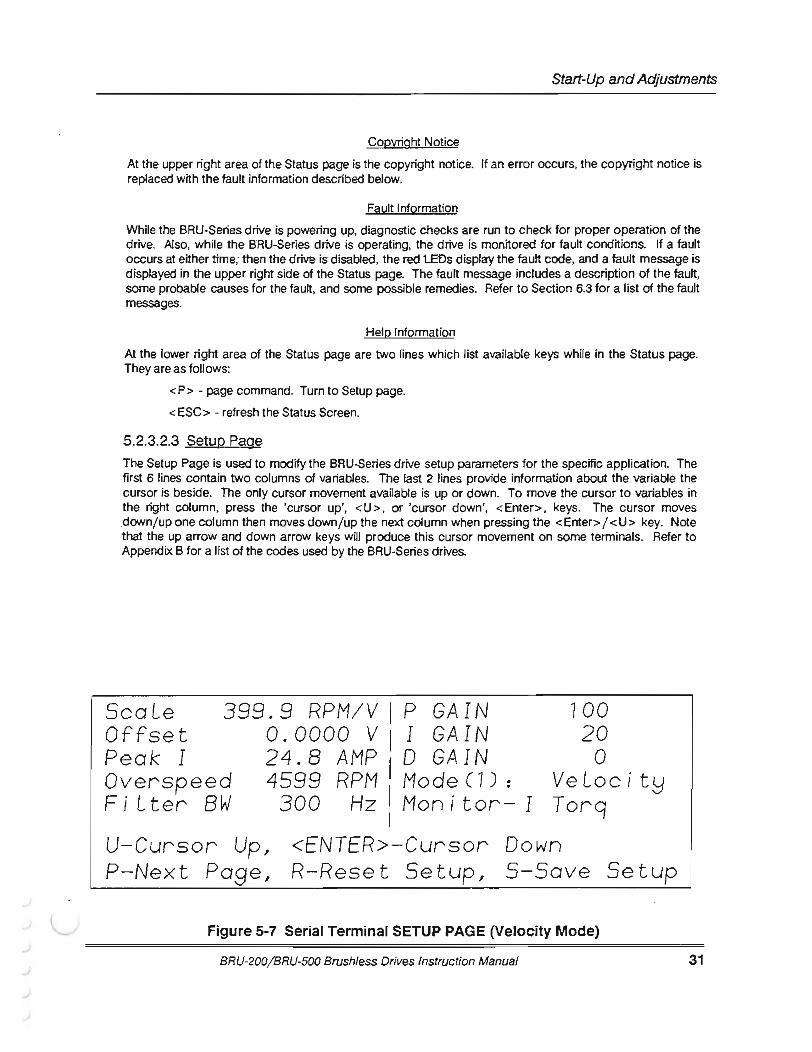
5.2.3.2.3 Setup Page The Setup Page is used to modify the BRU-Series drive setup parameters for the specific application. The first 6 lines contain two columns of variables. The last 2 lines provide information about the variable the cursor is beside. The only cursor movement available is up or down. To move the cursor to variables in the right column, press the 'cursor up', <U>, or 'cursor down', <Enter>, keys. The cursor moves .downj up one column then moves downj up the next column when pressing the < Enter> 1 < U > key. Note that the up arrow and down arrow keys will produce this cursor movement on some terminals. Refer to Appendix B for a list of the codes used by the BRU-Series drives.
GAIN GAIN
399.9 RPM/ VI p 0. 0000 v I I 24.8 AMP 0 GAIN 4599 RPM II Mode ( 7) :
ScaLe Offset Peak I Over s peed FiLter BW 300 Hz Mon i tor- I
I
700 20
0 Ve Loc it!:j Torq
U-Cursor Up, P-Nex t Page,
<ENTER> -Cursor Down R- Reset Setup, 5-Save Se tup
Figure 5-7 Serial Terminal SETUP PAGE (Velocity Mode}
BRU-200/ BRU-500 Brushfess Drives Instruction Manual 31
Start-Up and Adjustments
32
ScaLe Offset Peak I Over speed FiLter
2. 49 AMP IV I
o. oooo v 1
24.8 AMP 4599 RPM II Mode C2) :
300 Hz Mon i tor- I I
Torque Torq
U-Cursor Up, <ENTER>-Cursor Down P-Next Page, R-Reset Setup, S-Save Setup
Figure 5-8 Serial Terminal SETUP PAGE (Torque Mode)
Period 7 . 00 SEC I P GAIN 700 Step VeL 300 RPM I I GAIN 20 Peak I 24.8 AMP D GAIN 0 Over speed 4599 RPM I Mode (3) , Tune FiLter 300 Hz Mon i tor- I Torq
I U-Cursor Up, <ENTER>-Cursor Down P-Next Page, R-Reset Setup, S-Save Setup
Figure 5-9 Serial Terminal SETUP PAGE (Tune Mode)
Dist Max VeL Step I Over speed Fi Lter
7 . 0 REV I P GAIN 7 00 3000 RPM I I GAIN 20
8. 3 AMP D GA IN 0 4599 RPM
1
1 Mode (4) : Auto Tune 300Hz Monitor-I Torq
I U-Cursor Up, <ENTER>-Cursor Down P-Next Page, R-Reset Setup, S-Save Setup
Figure 5-10 Serial Terminal SETUP PAGE (Auto-Tune Mode)
BRU-200/BRU-500 Brushless Drives Instruction Manual
(
r
(
Start-Up and Adjustments
How to change a variable
The variables are stored in the PM (Personality Module) which is either a nonvolatile RAM or an EEPROM. When new data is entered, the data is NOT STORED UNTIL THE < S > KEY IS PRESSED. Thus you can adjust the tuning until satisfied and then save the variables. If not satisfied with the new values, then the previous values can be restored by resetting the drive as long as the <S> key was not pressed. A write protect jumper is available to prevent the variables from being altered. Make sure the write protect jumper is in the non-write-protect position before powering up the drive if it is going to be tuned (refer to Figure 5-2.). Under· no circamstance, · shoa1d·1he write-protect jumper be moved while power is applied. The result could be a damaged personality module.
To change the value of a variable, move the cursor, using the <U > or <Enter> keys to the location immediately to the left of the variable to be changed and then enter the new value. As the data is being entered, the present data for that variable will be erased off the screen and the new data will be displayed as it is being entered. Press <Enter> to complete the data entry. While entering data for a variable, if you wish to restore the previous value, press the <ESC> key to ignore the present value and restore the previous value.
Available commands
While on the Setup Page, the user has several commands available. They are as follows:
<ESC> - Refresh the Setup screen if not presently changing a variable, or restore previous data if presently changing a variable.
< P > - Tum to the Status Page.
< R > - Reset personality tuning back to the factory settings.
< S > - Save present tuning into the personality.
< U > ,up arrow (on Tandy 1 02) - Move the cursor up.
<ENTER>,dnarrow (on Tandy 102)- Move the cursor down.
<0> to <9>,<.> -Data entry.
<<> ,left arrow (on Tandy 102) - decrease the value of the variable. Active only for 'Offset', 'P GAIN', 'I GAIN', and 'D GAIN'.
<> >,right arrow (on Tandy 102) - increase the value of the variable. Active only for 'Offset', 'P GAIN', 'I GAIN', and 'D GAIN'.
User selected variables
Tuning variables for the BRU-Series drive may be modified through the user terminal. The setup screen for each of the four modes is different. Refer to Figures 5-7, 5-8, 5-9, and 5-10.
BRU-200/ BRU-500 Brushless Drives Instruction Manual 33
Start-Up and Adjustments
34
CAUTION THE BRU-200 AND BRU-500 RESPOND TO A CHANGE IN THE SETUP PAGE DATA EVEN WHEN ENABLED
The variables available are described as follows: Scale - (velocity and torque mode) For velocity mode, the data entered for Scale is in RPMfV and is used to scale the motor speed for a given voltage at the VCS input. The full scale voltage input at VCS is 10 V. Normally the scaling should be set for full scale RPM/ 10 to provide the maximum speed resolution. For torque mode, the data entered is in AMP fV and is used to scale the torque producing current for a given voltage at the VCS input. Normally, Scale in torque mode should be set for the drive module peak current/ 10.
Period - (tune mode) The Period variable is used with Step Vel in tune mode to define the output of the internal square-wave function generator. Period refers to the length of time in seconds required to complete one square-wave cycle. Note that the function begins as soon as the drive is enabled, and that the motion of the motor will be centered around the motor position when the drive is enabled.
Dist - (auto-tune mode) The Dist variable is used to define the working distance that the servo may move in auto-tune mode to identify the load inertia. The Dist value is intended to be a maximum distance moved in the positive and negative direction around the starting point, however, due to the open loop control method used and the unknown influences such as gravity, friction, etc., the distance moved can exceed this value. Setting Dist to 0 results in unidirectional motion in the direction of the sign of the Max Vel parameter. Distance is entered in units of motor revolutions. Refer to Section 5.3.1 for more information on auto-tune.
Offset - (velocity and torque mode) For velocity and torque modes, the Offset variable is used to remove offsets from the user input at VCS. This variable is in units of volts and can be a positive or negative value. NOTE: Offset can also be adjusted by potentiometer R107 (BRU-200) or R106B (BRU-500). Refer to Drawing 9101-0139 and 9101-1061.
Step Vel - (tune mode) Tune mode disconnects the VCS input from the velocity regulator and internally connects a square-wave function generator which produces step velocity inputs to the velocity regulator. This is used to tune the BRU-Series drive when used in velocity mode. Step Vel is the amplitude of the function generator and is in units of RPM. Step Vel can be either positive or negative. If positive, the initial step velocity will be in the positive direction and if negative, it will be in the negative direction. While in this mode, P GAIN, I GAIN, D GAIN, and Filter BW can be adjusted. Note that when I GAIN is > 0, the motor position will not drift.
Max Vel - (auto-tune mode) The Max Vel variable is used to set the maximum speed of the servo motor during auto-tune. If the Dist variable is set to 0 in order to achieve unidirectional motion, the sign of Max Vel determines the direction of rotation. Max Vel is entered in units of RPM. Refer to Section 5.3.1 for information on auto-tune mode.
Peak I - (all modes except auto-tune) The Peak I variable is the peak current limit in Amps. It can be over-ridden by the external current limit only if external current limit is at a lower value.
Step I - (auto-tune mode) The Step I variable is the peak current setpoint (in Amps) used to accelerate the servo motor during auto-tune. When the Max Vel or half of the Dist values have been reached, the current reverses to accelerate the servo motor in the opposite direction. The value of the current to the motor will be Step I until auto-tune is completed.
BRU-200/BRU-500 Brushless Drives Instruction Manual
(
(
r Start-Up and Adjustments
Overspeed - (all modes) The Overspeed variable is the overspeed trip point in RPM. Exceeding this speed will result in a fault.
Filter BW - (velocity, torque and tune mode) Filter BW is the low pass filter which filters the output of the velocity regulator. It reduces the amplitude of the current pulses which can cause excessive noise (rattling sound) in the motor when the P GAIN, I GAIN, and/ or D GAIN values are high. Filter BW is entered in Hz.
P GAIN - (velocity ancttune· mode, inactive-· in torque mode) P GAIN is the proportional gain of the velocity regulator. It is multiplied by the difference between the input velocity command and the motor velocity to produce torque. Larger proportional gains reduce the dynamic following error of the motor velocity to commanded velocity (increases the bandwidth of the velocity regulator).
I GAIN - (velocity and tune mode, inactive in torque mode) I GAIN is the integral gain of the velocity regulator. The velocity error is continually added to itself. This sum is multiplied by the integral gain and is used to reduce the steady state error of the motor velocity to commanded velocity. I GAIN is generally used to improve the stiffness of the velocity regulator which reduces the effects of load disturbances. Excessive I GAIN, however, will result in overshoot and possible instability.
0 GAIN- (velocity and tune mode, inactive in torque mode) D GAIN is the damping gain of the velocity regulator. It is used for two purposes: 1) it can be used to reduce the overshoot caused by high I GAIN; 2) it can be used to minimize torsional resonance between the motor and load.
Mode - (all modes) The Mode variable is used to select the desired mode: Velocity, Torque, Tune, or Auto-tune. Velocity mode should be used when the VCS input is a velocity reference. Torque mode should be used when the VCS input is a torque reference. Tune mode is used to provide a square-wave velocity command for tuning the gains for the velocity regulator. Auto-tune automatically_tunes the velocity regulator gains. The tune and auto-tune modes are used only to tune the drive for velocity mode operation.
Monitor - (all modes) The Monitor variable allows one of 6 variables to be monitored on the monitor output on the Status page, the programmable monitor test point or the programmable monitor output, PS-3. The variables which can be monitored are listed in the monitor information portion of Section 5.2.3.2.2.
5.2.3.3 Multi-Drop Host Mode Serial Protocol
The BRU-Series drive has a serial port (P6) that can be configured as RS-232 (short distance interface up to 50 feet) and RS-422 Oong distance interface up to 4000 feet). The factory configuration of the drive is RS-232 which provides the terminal mode operation (refer to Section 5.2.3.2) for a human user interface with a VT-52 compatible terminal. Reliance Motion Control has a communication software program called EC COMM that easily configures an IBM compatible computer for VT-52 emulation. The RS-232 terminal mode is the usual way to communicate with the BRU-Series drives.
However, configuring a BRU-Series drive for RS-422 automatically replaces the terminal mode with a host computer communication protocol. In this mode of communication, each BRU-Series drive can be given a unique address and connected (in daisy-chain fashion) on a single serial link. Electro-Craft PRO-Series controllers that support host mode can be placed on the same daisy-chained serial link with the BRU-Series with each device having its own unique address.
BRU-200/ BRU-500 Brushless Drives Instruction Manual 35
Start-Up and Adjustments
36
For example, the host mode operation of the BRU-Series drives can provide the following functions:
Save and load the entire personality module (INTEL Hex File Format).
Real-time read and write of the BRU-Series parameters including PGAIN, IGAIN, SCALE, and OFFSET.
Real-time diagnostic and status monitor.
Terminal mode for multiple axes from the host computer.
Real-time monitor of variables such as average current.
The above would be implemented with the user's host software. The host mode of the BRU-Series drive simply provides a communication protocol (or language) that makes it easy for the host computer to communicate with the BRU-Series drive.
The host mode interface provides a very powerful and flexible communication protocol for use by a host computer. This implies that users will provide the necessary host software to perform the application function. The host mode operation of BRU-Series drives is an option that is not necessary for every application as it will require software to be created for the host computer. The host mode communication protocol is available as a separate document and can be obtained directly from Reliance Motion control and their authorized sales personnel.
5.3 Tuning Procedure
The BRU-Series drive has been designed to provide adequate tuning for many applications, that is, all of the necessary tuning information is contained in the personality module. However, for some applications some additional adjustments may be required. Two tuning modes have been included in the BRU-Series drive to help in tuning the system. The first is the auto-tune mode which consists of a ·self-tuning• algorithm. Auto-tune mode is designed for applications that require near-optimal performance. To optimize the BRU-Series drive tuning for a specific application, the tune mode can be used. All tuning and adjustments are accomplished via the serial interface (refer to Section 5.2.3.2.3).
5.3.1 Using Auto-Tune Mode
Auto-tune provides a method for tuning the servo drive connected to a machine without any special equipment other than the user terminal. Upon enabling the BRU-Series drive in auto-tune mode, the servo system will move in a rapid back-and-forth motion for 5 seconds and then halt.
WARNING
DO NOT ATTEMPT TO USE AUTO-TUNE WITH SYSTEMS WHICH HAVE GRAVITATIONAL AFFECTS. THE BRU-500 AND BRU-200 WILL NOT ATTEMPT TO HOLD INITIAL POSITION.
BRU-200/BRU-500 Brushless Drives Instruction Manual

(
(
Start-Up and Adjustments
Autc;tune implements a simple "self-tuning" algorithm that adjusts the tuning parameters P GAIN and I GAIN by computing the effect of the user's load as applied to the servo motor shaft. This method operates by commanding a constant current to the motor that produces a constant motor torque. The acceleration of the motor is measured and used to compute the gain of the system. Once the actual gain of the system is measured, the values of the tuning parameters P GAIN and I GAIN are adjusted to compensate for the change in gain. Auto-tune mode is selected by moving the cursor to the Mode line on the Setup page of the User interface (refer to Section 5.2.3.2.3). Once selected, enabling the BRU-Series drive starts auto-tune which causes the servo motor to rapidly accelerate and decelerate. After 5 seconds, the current command to the motor is set to· zero which should haft ·motion:· ·- - --
WARNING
AT THE COMPLETION OF AUTO-TUNE, VOLTAGE REMAINS APPUED TO THE MOTOR UNTIL THE BRU-500 OR BRU-200 IS DISABLED.
Three parameters control the operation of auto-tune mode: Dist, Max Vel, and Step L The Dist parameter is used to limit the distance moved from the starting position. The maximum value for Dist is 4 motor rotations. Due to the open-loop nature of the auto-tune and the unpredictable affects of gravity, friction, etc., the distance may be exceeded. During auto-tune, exceeding the Dist value will not generate a fault condition. The Max Vel parameter is used to set a maximum velocity during auto-tune. It can be a positive or negative value. If Dist is set to 0, the servo motor will move in one direction with the sign of Max Vel determining the direction. Step I determines the value of motor current used to accelerate and decelerate the motor. The maximum allowed value of Step I is limited to rated current of the motor. These three parameters are set to default values upon entering auto-tune mode which should be sufficient for most loads.
The parameters adjusted by auto-tune are P GAIN, I GAIN, and D GAIN. D GAIN is always set to 0. P GAIN and I GAIN are adjusted proportionally to the change in gain of the system. There are certain conditions where erroneous values are computed for P GAIN and I GAIN. These conditions are as follows:
1.) Dist is set too low. This condition results in very rapid reversal of the servo motor rotation and causes it to make a buzzing sound.
2.) Max Vel is set too low. This condition results in very rapid reversal of the servo motor rotation and causes it to make a buzzing sound.
3.) Step I is set too low. There is no servo motor motion.
4.) FAC andj or RAC enabled. This condition can be checked by observing the Status page on the user terminal to see if FAC andj or RAC are displayed. The condition is evidenced by no motion or a halting of the back-and-forth motion.
These conditions will generally result in very high values for P GAIN (999 is maximum) and I GAIN (999 is maximum) which may result in instability when returned to the velocity mode of operation.
The procedure for using auto-tune is as follows:
1.) Make sure the system is connected and is operating proper1y by following the initial start-up procedure in Sec. 5.1.
2.) Connect the user terminal to connector P6 on the BRU-Series drive.
3.) With the drive disabled, apply power.
BRU-200/BRU-500 Brushless Drives Instruction Manual 37

Start-Up and Adjustments
38
4.) Press <P> to tum to the SETUP page.
5.) Move the cursor to Mode and select auto-tune mode by entering 4 followed by <ENTER>. The terminal screen should appear as shown in Figure 5-10.
6.) Adjust Dist, Max Vel, and Step I if required. Note that the default values should provide good results for most systems. The Step I should be reduced if the torque will exceed machine specifications.
7.) Tum to the STATUS page by pressing <P> to insure that FAC and RAC are not enabled then return to the SETUP page by pressing < P > again. ·
8.) Enable the BRU-Series drive to start the auto-tune process which will cause the motor to move in a back-and-forth motion.
9.) The computed values for P GAIN and I GAIN will appear on the screen after 5 seconds. The BRU-Series drive signals completion by commanding 0 current to the motor and se.nding a "beep" to the user terminal.
1 0.) Move the cursor to Mode and select velocity mode by entering 1 followed by <ENTER> .
11 .) Press < S > if the present tuning is to be saved into the personality module. Saving the parameters requires that the write protect jumper J10 is set to the appropriate position (refer to Figure 5-2). Attempts to move J10 with power applied to the servo drive may result in damaging the personality module.
5.3.2 Using Tune Mode
The tune mode is designed to optimally tune the BRU-Series drive. For most applications, the default tuning values or the results of auto-tune should provide adequate tuning. For applications with particular requirements, tune mode can be used to fine tune the system. A suggested tuning procedure for velocity mode operation is discussed below. This procedure assumes that the system, including the machine the motor is connected to, can tolerate small-signal step velocity changes. There is essentially no tuning required for torque mode; P GAIN, I GAIN, and D GAIN have no effect in torque mode.
The tuning of the velocity regulator is accomplished by changing the variables P GAIN, I GAIN, and D GAIN. The P GAIN is the proportional gain of the velocity regulator. In general, increasing P GAIN reduces the time required to reach the commanded velocity. The I GAIN is the integral gain of the velocity regulator. Integration in the velocity regulator forces the motor velocity to precisely follow the commanded velocity with no error under steady state conditions (no changes in velocity command or load). Increasing I GAIN increases the stiffness, or the ability to reject load disturbances. Increasing I GAIN also, however, increases the amount of velocity overshoot when responding to a step change in velocity. Too much I GAIN can cause the system to go unstable. The D GAIN is the damping gain. It is used to reduce the amount of overshoot caused by the I GAIN term. It can also be used to minimize torsional resonance between the motor and load in some systems. A block diagram of the velocity regulator is shown in Figure 5-11 .
BRU-200/BRU-500 Brushless Drives Instruction Manual
(
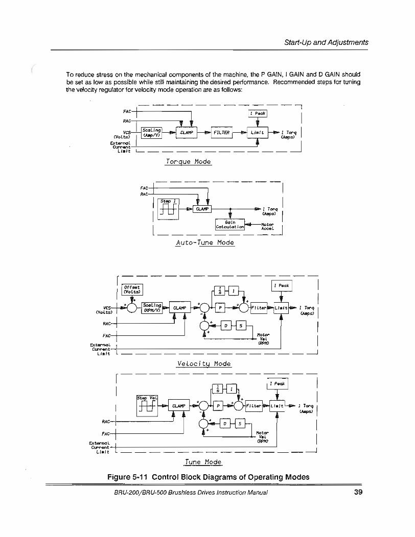
(
(
Start-Up and Adjustments
To reduce stress on the mechanical components of the machine, the P GAIN, I GAIN and D GAIN should be set as low as possible while still maintaining the desired performance. Recommended steps for tuning the velocity regulator for velocity mode operation are as follows:
------------, FAC-+-------------. I RAC-,------------.
vcs CVoLts)
ExtemaL Clrrent
Ll•lt
I (Mp/V) I L_ __________ _j
Torque Mode
FAC-+---------------,
Auto-Tune Mode
FAC-+-----------------'
Ext..-noL
1 Torq I CA8ps)
Ll•lt --- --- --- --- --- --- --- --- -- --- -- --- -- _J
FAC-+---------------'
ExternaL
Ll•lt -- --- --- --- --- --- -- --- -- --- -- --- -- _J
Tune Mode
Figure 5-11 Control Block Diagrams of Operating Modes
BRU-200/BRU-500 Brush/ess Drives Instruction Manual 39
Start-Up and Adjustments
1.) Make sure the system is connected and is operating properly by following the initial start-up procedure in Sec. 5.1.
2.) Connect the user. terminal to connector P6 on the BRU-Series drive.
3.) Wrth the drive disabled, apply power.
4.) Press the <ESC> key on the terminal to enter the STATUS page and check that the status indicates MODE•. If the ·servo drive is in 'TRQ MODE' then press the < P > key to tum to the SETUP page. Move the cursor up to the MODE line and type '1' followed by <Enter> to change to VELocity MODE, then press <P> to return to the STATUS page. The status should now indicate 'VEL MODE'.
5.) Press <P> to page to SETUP page.
6.) Move the cursor to SCALE. Set the desired scaling on the velocity command input While in tune mode it may be helpful to reduce the scaling to a small value such as 50 RPMJV since the scaling of the programmable monitor output (on connector P5-3 or test point MON) is scaled by this value. This will allow full D I A converter resolution over a 500 RPM range.
7.) Offset is most easily adjusted with the position controller connected and will therefore be tuned later (refer to step 22).
8.) Set the desired Peak I (Peak Current) and the Overspeed trip point.
9.) Turn off the Filter BW by setting it to 0.
10.} (Optional} Follow steps 5 through 10 for Auto-tune procedure in Section 5.3.1 to provide a near-optimal tuning starting point.
11 .) Move the cursor again to Mode and select Tune mode. Connect an oscilloscope to the test point MON or to PS pin 3.
12.) Move the cursor to Period and set the desired square wave cycle time. A Period is the time required to complete one cycle of the square wave. The value of Period will depend on the user and the application. Avoid setting Period to a high value which will allow the system to reach the end of travel with the Step Vel value programmed (see step 13}. The Period should not need to be set to Jess than 0.02 seconds.
13.) Move the cursor to Step Vel and set the desired step velocity of the internal square wave generator. This value will generally be between 50 and 500 RPM. Note that an excessive step velocity or a low Peak I setting can cause the servo drive to enter current limit. This should be avoided while tuning the BRU-Series drive. You can be sure that the BRU-Series drive is not entering current limit by turning to the Status Page while the BRU-Series drive is enabled and making sure that the I Limit message does not flash during a motor speed reversal. If it does appear, Step Vel must be reduced or Peak I must be increased.
14.) Enable the BRU-Series drive and observe the motion of the motor shaft. Ensure that FAC and RAC are not enabled if no motion occurs. Disable the drive and adjust Period and Step Vel if necessary.
15.} Change Monitor to Tach by moving the cursor to the monitor line and pressing '3'.
16.} Set I GAIN to a low value (no noticeable overshoot} and set D GAIN to 0. While observing the tach at the monitor output with an oscilloscope, increase P GAIN until the desired rise time is obtained.
40 BRU-200/BRU-500 Brushless Drives Instruction Manual

(
r (
17.)
18.)
19.)
20.)
21.)
22.)
23.)
24.)
Start-Up and Adjustments
Increase I GAIN until the acceptable limit for the amount of overshoot is reached. The Tach and I Torq signals should look similarto those shown in Figure 5-12.
If more stiffness is required, increase I GAIN beyond the desired overshoot. Then increase D GAIN to reduce the overshoot back down to the acceptable limit.
After the P GAIN and I GAIN are adjusted, if there is a ringing on the tachometer due to torsional resonance between the motor and load, then increaseD GAIN until oscillation is acceptable.
Reduce Filter BW until the overshoot begins to increase.
To adjust offset, disable the drive and connect the position controller.
Set the mode to Velocity mode and enable the system. The position controller should be holding the shaft position still. Read the velocity command input voltage (VCS) at P1 pins 3 to 4 or the VEL CMD test point using a digital voltmeter. NOTE: The velocity offset can also be adjusted by potentiometer R106B (BRU-500) or R107 (BRU-200). Refer to drawings 9101-0139 or 9101-1061.
Enter the voltage read for Offset. The velocity command voltage should drop to 0 volts.
Press 'S' to save the offset into the personality module.
BRU-200/BRU-500 Brushless Drives Instruction Manual 41
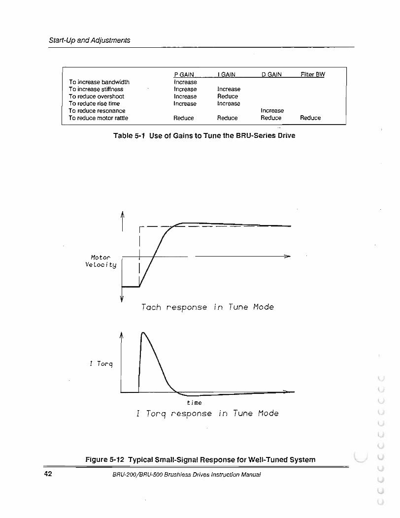
Start-Up and Adjustments
PGAIN I GAIN DGAIN To increase bandwidth Increase To increase stiffness Increase Increase To reduce overshoot Increase Reduce To reduce rise time Increase Increase To reduce resonance Increase To reduce motor rattle Reduce Reduce Reduce
Table 5-1 Use of Gains to Tune the BRU-Series Drive
Motor' VeLocity
Tach response in Tune Mode
time I Torq response in Tune Mode
FilterBW
Reduce
Figure 5-12 Typical Small-Signal Response for Well-Tuned System
42 BRU-200/BRU-500 Brushless Drives Instruction Manual
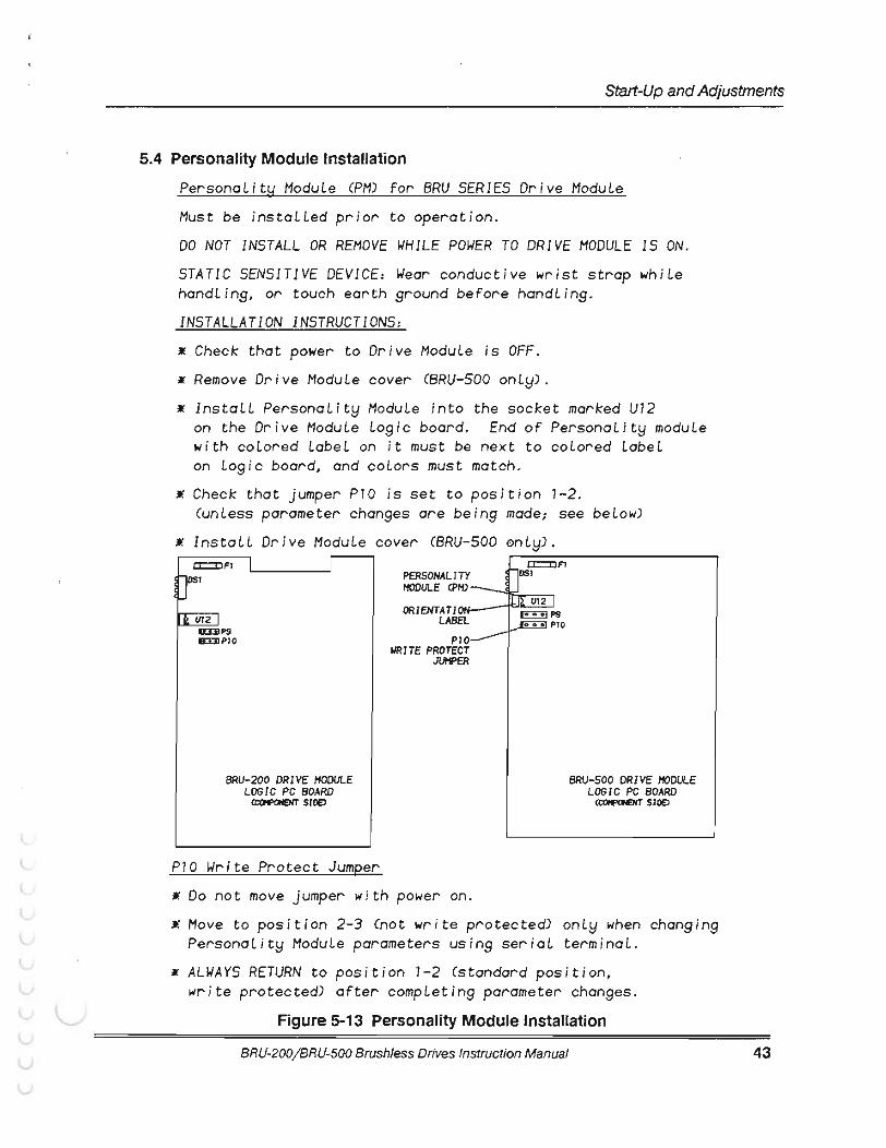
(
(
Start-Up and Adjustments
5.4 Personality Module Installation
PersonaLity ModuLe CPM) for BRU SERIES Drive ModuLe
. Must be instaLLed prior to operation. DO NOT INSTALL OR REMOVE WHILE POWER TO DRIVE MODULE IS ON.
STATIC SENSITIVE DEVICE: Wear conductive wrist strap whiLe handLin9, or touch earth 9round before handLin9.
INSTALLATION INSTRUCTIONS: • Check that power to Drive ModuLe is OFF. • Remove Drive ModuLe cover CBRU-500 onLy) .
• InstaLL PersonaLity ModuLe into the socket marked U12 on the Drive Module Lo9ic board. End of PersonaLity moduLe with coLored LabeL on it must be next to coLored LabeL on Lo9ic board, and coLors must match.
• Check that jumper P10 is set to position 7-2. (unless parameter chan9es are bein9 made; see beLow)
• InstaLL Drive ModuLe cover CBRU-500 0nly) .
Ill. cn2 J a:EIIP9 &:DIPIO
BRU-200 DRIVE MODULE LOGIC PC BOARD
CCCifi'OHE)IT SlDEJ
P10 Write Protect Jumper
PERSONALITY l'fODULE CPH)
ORIENTATION LABEL
P10 WRITE PROTECT
JUHPER
• Do not move jumper with power on.
BRU-500 DRIVE MODULE LOGIC PC BOARD
CCOifPOHENT SlOE)
• Hove to position 2-3 (not write protected) onLy when chan9in9 PersonaLity ModuLe parameters usin9 seriaL terminaL.
• ALWAYS RETURN to position 1-2 (standard position, write protected) after compLetin9 parameter chan9es.
Figure 5-13 Personality Module Installation
BAU-200/ BRU-500 Brushless Drives Instruction Manual 43
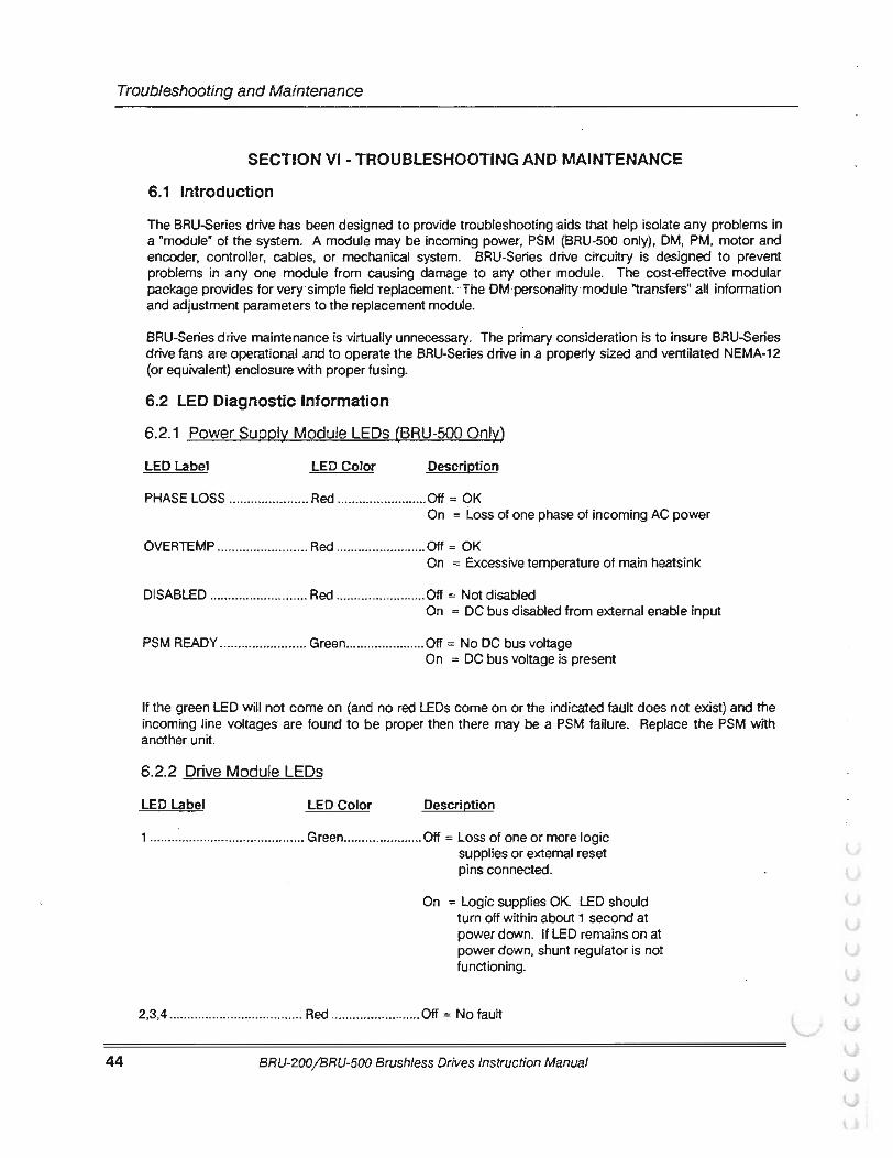
Troubleshooting and Maintenance
44
SECTION VI -TROUBLESHOOTING AND MAINTENANCE
6.1 Introduction
The BRU-Series drive has been designed to provide troubleshooting aids that help isolate any problems in a "module" of the system. A module may be incoming power, PSM (BRU-500 only), OM, PM, motor and encoder, controller, cables, or mechanical system. BRU-Series drive circuitry is designed to prevent problems in any one module from causing damage to any other module. The cost-effective modular package provides for very· simple field replacement. ·The OM personality module "transfers" all information and adjustment parameters to the replacement module.
BRU-Series drive maintenance is virtually unnecessary. The primary consideration is to insure BRU-Series drive fans are operational and to operate the BRU-Series drive in a properly sized and ventilated NEMA-12 (or equivalent) enclosure with proper fusing.
6.2 LED Diagnostic Information
6.2.1 Power Supply Module LEOs (BRU-500 Only)
LED Label LED Color Description
PHASE LOSS ...................... Red ......................... Off = OK On = i..oss of one phase of incoming AC power
OVERTEMP ......................... Red ......................... Off = OK On = Excessive temperature of main heatsink
DISABLED ........................... Red ......................... Off = Not disabled On = DC bus disabled from external enable input
PSM READY ........................ Green ...................... Off = No DC bus voltage On = DC bus voltage is present
If the green LED will not come on (and no red LEOs come on or the indicated fault does not exist) and the incoming line voltages are found to be proper then there may be a PSM failure. Replace the PSM with another unit.
6 .2.2 Drive Module LEDs
LED Label LED Color Description
1 ........................................... Green ...................... Off = Loss of one or more logic supplies or external reset pins connected.
On = Logic supplies OK LED should tum off within about 1 second at power down. If LED remains on at power down, shunt regulator is not functioning.
2,3,4 ..................................... Red ......................... Off = No fault
BRU-200/BRU-500 Brushless Drives Instruction Manual
l
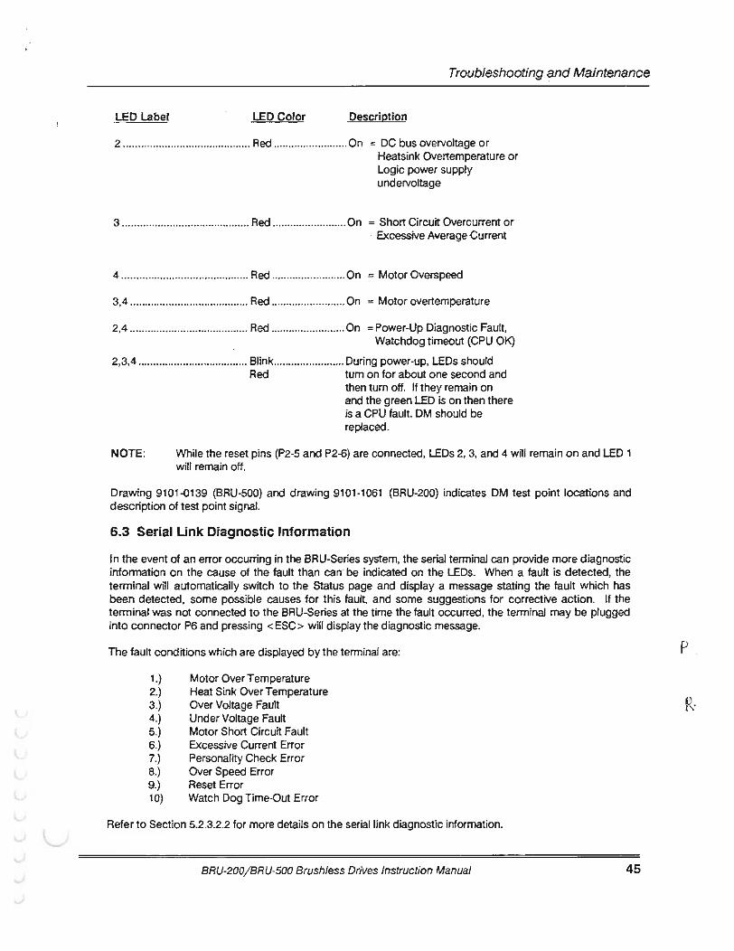
(
r Troubleshooting and Maintenance
LED Label LED Color Description
2 ........................................... Red ......................... On = DC bus overvoltage or Heatsink Overtemperature or Logic power supply undervoltage
3 ........................................... Red ......................... On = Short Circuit Overcurrent or · Excessive Average Current
4 ........................................... Red ......................... On = Motor Overs peed
3,4 ........................................ Red ......................... On = Motor overtemperature
2,4 ........................................ Red ......................... On =Power-Up Diagnostic Fault, Watchdog timeout (CPU OK)
2,3,4 ..................................... Blink ........................ During power-up, LEOs should Red tum on for about one second and
then turn off. If they remain on and the green LED is on then there is a CPU fault. DM should be replaced.
NOTE: While the reset pins (P2-5 and P2-6) are connected, LEOs 2, 3, and 4 will remain on and LED 1 will remain off.
Drawing 9101-0139 (BRU-500) and drawing 9101-1061 (BRU-200) indicates OM test point locations and description of test point signal.
6.3 Serial Link Diagnostic Information
In the event of an error occurring in the BRU-Series system, the serial terminal can provide more diagnostic information on the cause of the fault than can be indicated on the LEOs. When a fault is detected, the terminal will automatically switch to the Status page and display a message stating the fault which has been detected, some possible causes for this fault, and some suggestions for corrective action. If the terminal was not connected to the BRU-Series at the time the fault occurred, the terminal may be plugged into connector P6 and pressing < ESC> will display the diagnostic message.
The fault conditions which are displayed by the terminal are:
1.) 2 .) 3.) 4.) 5.) 6.) 7.) 8.) 9.) 10)
Motor Over Temperature Heat Sink Over Temperature Over Voltage Fault Under Voltage Fault Motor Short Circuit Fault Excessive Current Error Personality Check Error Over Speed Error Reset Error Watch Dog Time-Out Error
Refer to Section 5.2.3.2.2 for more details on the serial link diagnostic information.
BRU-200/BRU-500 Brushless Drives Instruction Manual 45
p
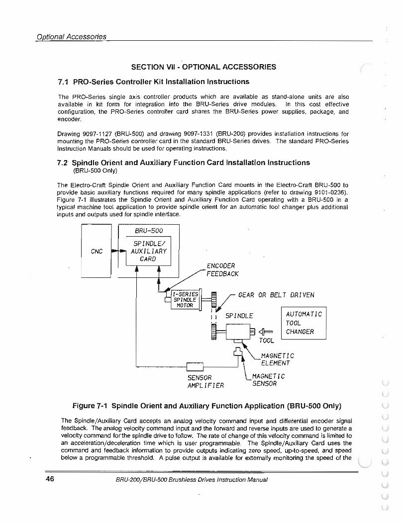
Opffona!Accessories
46
SECTION VII - OPTIONAL ACCESSORIES
7.1 PRO-Series Controller Kit Installation Instructions
The PRO-Series single axis controller products which are available as stand-alone units are also available in kit form for integration into the BRU-Series drive modules. In this cost effective configuration, the PRO-Series controller card shares the BRU-Series power supplies, package, and encoder.
Drawing 9097-1127 (BRU-500) and drawing 9097-1331 (BRU-200) provides installation instructions for mounting the PRO-Series controller card in the standard BRU-Series drives. The standard PRO-Series Instruction Manuals should be used for operating instructions.
7.2 Spindle Orient and Auxiliary Function Card Installation Instructions (BRU-500 Only)
The Electro-Craft Spindle Orient and Auxiliary Function Card mounts in the Electro-Craft BRU-500 to provide basic auxiliary functions required for many spindle applications (refer to drawing 91 01-0236). Figure 7-1 illustrates the Spindle Orient and Auxiliary Function Card operating with a BRU-500 in a typical machine tool application to provide spindle orient for an automatic tool changer plus additional inputs and outputs used for spindle interface.
BRU-500 SPINDLE/
CNC AUXILIARY CARD
ENCODER FEEDBACK
1
v GEAR OR BELT DR /YEN
1 1 SPINDLE AUTOMATIC TOOL CHANGER
MAGNETIC ELEMENT
MAGNETIC SENSOR
Figure 7·1 Spindle Orient and Auxiliary Function Application (BRU-500 Only)
The Spindle/Auxiliary Card accepts an analog velocity command input and differential encoder signal feedback. The analog velocity command input and the forward and reverse inputs are used to generate a velocity command for the spindle drive to fonow. The rate of change of this velocity command is limited to an acceleration/deceleration time which is user programmable. The Spindle/Auxiliary Card uses the command and feedback information to provide outputs indicating zero speed, up-to-speed, and speed below a programmable threshold. A pulse output is available for externally monitoring the speed of the
BRU-200/BRU-500 Brushless Drives Instruction Manual
(
(
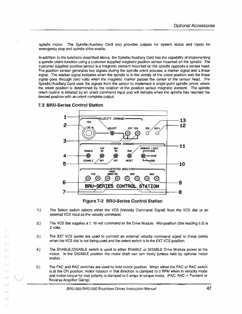

Optional Accessories
48
6.) The VCS test points are used to monitor the VCS command to the Drive Module.
7.) The programmable monitor test points may be used to monitor the signal selected as the Monitor signal using a serial terminaL Information on the choice of signals that can be output to these test points is shown by moving the cursor to the Monitor line on the serial terminal Setup page.
8.) The MVO test points are used to monitor the Motor Velocity Output (tachometer) from the Drive Module.
9.) The MCO test points are used to monitor the Motor Current Output (current command) from the Drive Module.
10.) The current limit switch sets the peak current limit to 25, 50, or 100% of the Drive Module peak current rating.
11.) The RUN/RESET switch is used to reset the Drive Module fault circuits by momentarily setting to RESET and then to RUN.
12.) The OUT1 LED is ON when the contacts of the OUT relay are closed in the Drive Module.
13.) The SSO LED is OFF when there is either a Drive Module fault or the reset switch is activated.
NOTE: The RED test points are + (plus). and the BLACK test points are- (minus) . Black test points PROG MONITOR, MVO, MCO, (and VCS when SELECT is set to VCS dial) are connected to signal COMMON on the Drive Module.
J101 P101
BRU-SERIES CONTROL STATION
PI N 9101-0200
CABLE ASSY PI N 910 1-0202-0 10
BRU-SERIES DRIVE MODULE
CSIDE VIEW) l.[)l.[) ')Q_
N CL
Figure 7-3 BRU-Series Control Station Connection Diagram
BRU-200I BRU-500 Brushless Drives Instruction Manual
(
(
(
(.
(.

(
(
( Optional Accessories
7.4 RS232C/RS422 Converter
The RS232C/RS422 converter option card mounts in the Electro-Craft BRU-200 and BRU-500 to provide data conversion between RS232C and RS422 standards. This option card is useful when multiple BRU-Series drives are connected together on a daisy-chain serial link using the multi-drop host mode serial protocol. Drawing 9101-0334 shows the board outline and connections.
BRU-200/BRU-500 Brushless Drives Instruction Manual 49
Application Guidelines
50
SECTION VIII- APPLICATION GUIDELINES
8.1 Torque Sharing Operation of BRU-Series Drives
8. 1.1 General Description
The BRU-Series drives provide the capability to operate in a torque-sharing mode for applications where multiple motor shafts are rigidly coupled together to drive a common load. The torque sharing configuration may be used with either servo or spindle drives.
The torque sharing mode would typically be used in situations where:
1.) A lead screw or shaft is driven from each end;
2.) Two or more lead screws must be driven;
3.) Drive train torque must be distributed to protect the machine mechanics.
Some of these cases are illustrated in Figure 8-1 .
The BRU-Series servo drives provide a flexible microprocessor-based control which allows operation in the torque sharing mode without requiring additional external hardware. All setup and tuning changes can be made using a serial terminal, so there are no components to change and no potentiometers to adjust.
8.1.2 Theory of Operation
The torque sharing mode requires that one drive (designated as the master drive) operates as a velocity controller, and one or more drives (referred to as slave drives) operate as torque controllers. A serial terminal is used to set the mode, scaling, and tuning parameters. Detailed instructions for setup of the drive using the terminal can be found in Section 5.2.3.2.
The torque signal (MCO) from the master drive is used as the command for the slave drive. This is a ± 10 Volt signal, where 10 V corresponds to the peak current of the master drive. For example, if a BRU-500 DM-50 is used as the master drive, a 10 Volt MCO signal corresponds to 50 amps of motor current, and the polarity of the MCO signal determines whether positive or negative torque is produced. The scaling of the MCO output from the master drive is then 5 Amps per Volt (AjV). The command scaling of the slave drive, operating in torque mode, is also in AfV. For equal sharing of the torque, the slave command scaling is set to the same value as the master drive MCO scaling.
NOTE: If the master and slave motors have different torque constants (Kt), this must be taken into account when determining the slave command scaling in order to obtain equal torque sharing.
BRU-200/BRU-500 Brushless Drives Instruction Manual
(
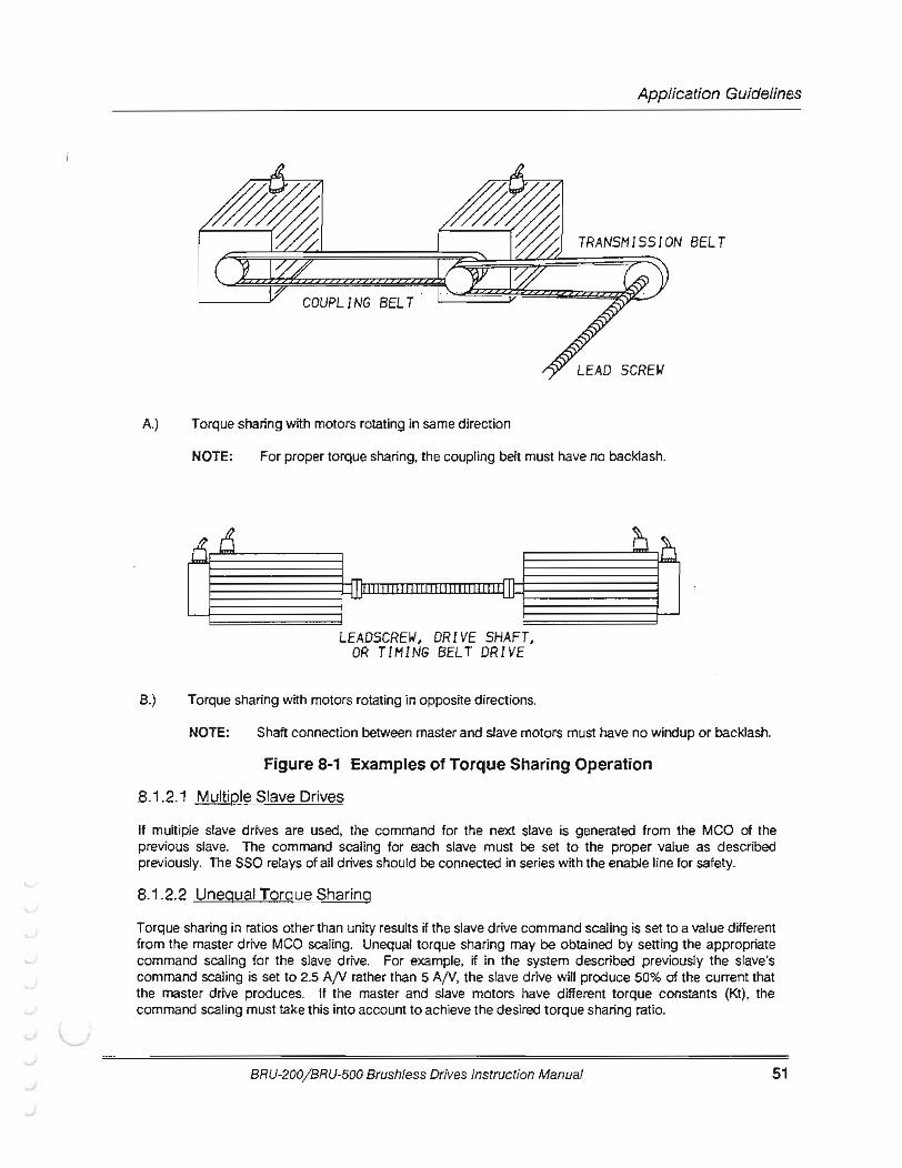
(
r Application Guidelines
COUPLING BELT
A.) Torque sharing with motors rotating in same direction
NOTE: For proper torque sharing, the coupling belt must have no backlash.
LEADSCREW, DRIVE SHAFT, OR TIMING BELT DRIVE
B.) Torque sharing with motors rotating in opposite directions.
NOTE: Shaft connection between master and slave motors must have no windup or backlash.
Figure 8-1 Examples of Torque Sharing Operation
.8.1 .2.1 Multiple Slave Drives
If multiple slave drives are used, the command for the next slave is generated from the MCO of the previous slave. The command scaling for each slave must be set to the proper value as described previously. The SSO relays of all drives should be connected in series with the enable line for safety.
8.1.2.2 Unequal Torgue Sharing
Torque sharing in ratios other than unity results if the slave drive command scaling is set to a value different from the master drive MCO scaling. Unequal torque sharing may be obtained by setting the appropriate command scaling for the slave drive. For example, if in the system described previously the slave's command scaling is set to 2.5 AjV rather than 5 AjV, the slave drive will produce 50% of the current that the master drive produces. If the master and slave motors have different torque constants (Kt), the command scaling must take this into account to achieve the desired torque sharing ratio.
BRU-200/BRU-500 Brushless Drives Instruction Manual 51
Application Guidelines
52
8.1.3 Set-Up Procedure
It is recommended that proper operation of the drive modules and motors is verified before beginning the torque sharing set-up. Offsets in the drives may be adjusted at this time. A drive which is trimmed in the velocity mode wUI stm be correctly adjusted when it is changed to torque mode.
8.1.3.1 Wiring Instructions
The recommended wiring for the master-slave configuration is "Shown ·in Figures 8-"2 and 8-3. There are two wiring diagrams shown for the two cases illustrated in Figure 8-1. Figure 8-2 shows the wiring for the case where master and slave motors rotate in the same direction, and Figure 8-3 is the wiring for the case when master and slave motors rotate in opposite directions. The wiring for these two cases is different because the polarity of the slave command is reversed in the two situations.
The forward and reverse clamps (FAC and RAC) are not shown in Figures 8-2 and 8-3. If it is desired to connect limit switches or other logic to these inputs, only the FAC and RAC inputs on the master drive should be used. The FAC and RAC inputs on the slave drives should be disabled by connecting FAC+ to FAC- and RAC+ to RAC-.
NOTE: It is important that the SSO relay is wired in the enable circuit as shown, so that all drives wm be disabled if there is a fault on any one of the drives. Otherwise, dangerous situations can result
8.1.3.2 Tuning
NOTE: The write protect jumper (P10) on the drive should be put in the write-enabled (2-3) position so that after the tuning is complete the values can be saved into the non-volatile memory on the BRU amplifier. It is recommended that after the set up is complete, the jumper be returned to the write-protected position.
All tuning of the master-slave system velocity control is accomplished by the velocity loop parameters of the master drive. The only adjustment required on the slave drives is setting the correct command scaling and adjusting the offset The command scaling for the slave drives was discussed previously in the Section 8.1.2.
If the offset of the slave drive has already been trimmed, in either velocity or torque mode, there is no need to adjust it again. Once the slave drive is set in the torque mode, the offset adjustment can be accomplished by the following procedure:
1.) Set up the slave drive in the torque mode, with the serial terminal connected, and with a command of zero;
2.) Set the programmable monitor to look at torque, and enable the drive; 3.) The torque displayed on the terminal is the offset in Amps; 4.) Calculate the offset in volts by dividing the offset in Amps from step 3 by the command scaling in
Amps per Volt and enter the negative of the result into the terminal as offset; 5.) Repeat steps 2 and 3 to check that the offset is correct, and then save the results with the 'S'
command on the terminal.
The velocity loop of the master drive is tuned as described in the tuning procedure for a standard drive. The velocity loop tuning should be done with all slave drives connected and enabled, because the slave drives will affect the velocity loop response.
BRU-200/BRU-500 Brushless Drives Instruction Manual
(
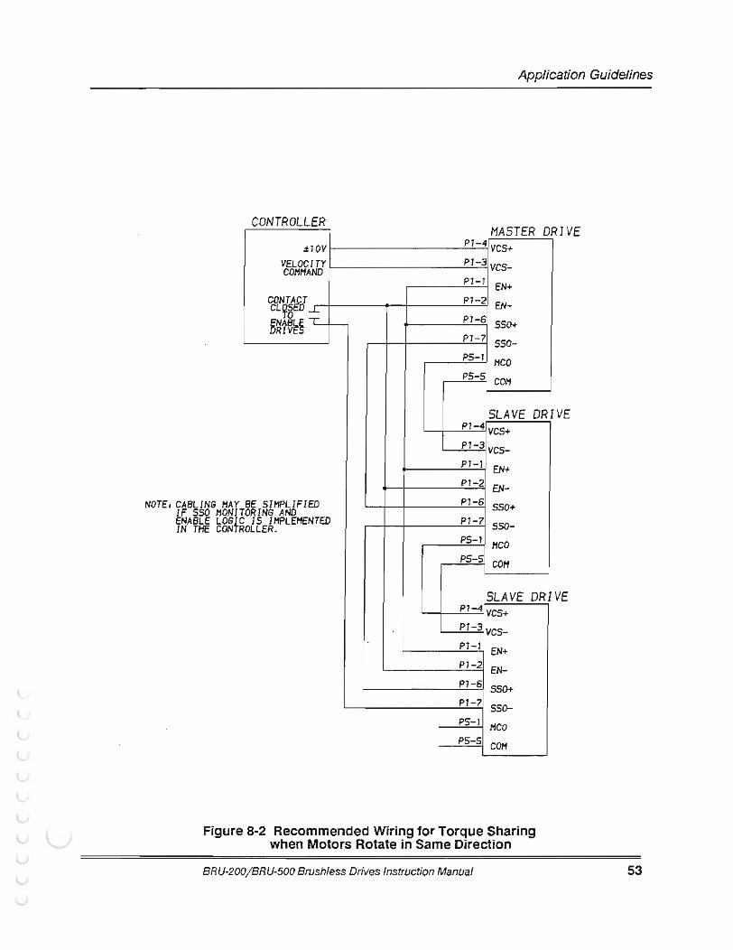
(
r Application Guidelines
CONTROLLER MASTER D RIVE .:t10V
VELOCITY COMMAND
CONTAJ? CL95 D ...1..
BE SIMPLIFIED NOTEs CABLING MAY IF SSO MONIT ENABLE LOGIC IN THE CONTR
DRING AND IS IMPLEMENTED
OLLER.
P1-4 VCS+ Pl-3 vcs-P7-7 EN+ P1-2 EN-P1-6 SSO+ P1-7 sso-PS-7 MCO PS-5 C0/'1
SLAVE DRI P1-4 VCS+ P1-3 vcs-Pl-7 EN+ P1-2 EN-Pl-6 SSO+ P1-7 sso-PS-1 HCO PS-5 C0/'1
SLAVE DRI Pl-4 VCS+ P1-3 vcs-P1-1 EN+ P1-2 EN-Pl-6 SSO+ P1-7 sso-PS-I HCO P5-S COM
Figure 8-2 Recommended Wiring for Torque Sharing when Motors Rotate in Same Direction
BRU-200/ BRU-500 Brushless Drives Instruction Manual
VE
VE
53
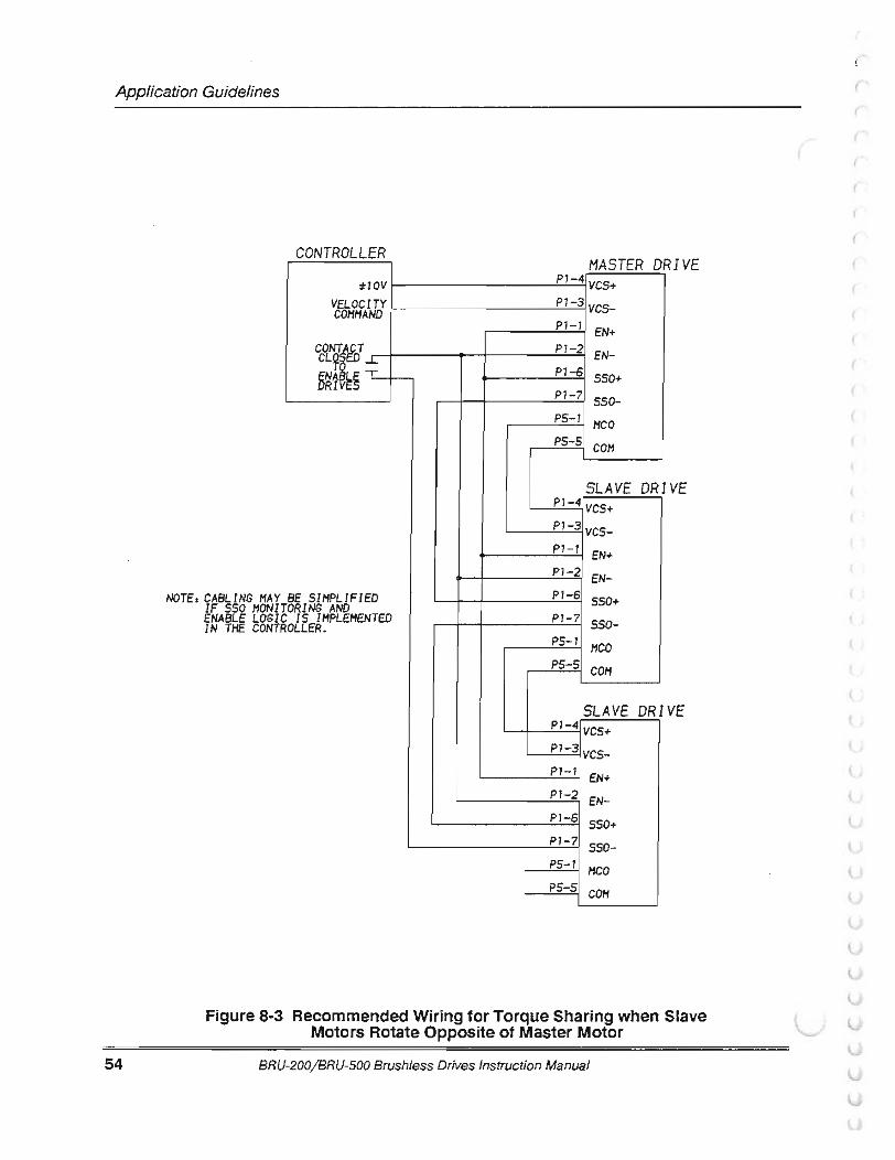
Application Guidelines
54
CONTROLLER .:tJOV
VELOCITY COMMAND
CL9 ...L. CONTr T
BE SIMPLIFIED TORING AND NOTEs CASU NG HAY
IF SSO HONI ENABLE LOGI IN THE CONT C IS IMPLEMENTED ROLLER.
MASTER D RIVE P1-4 YCS+ P1-3 vcs-Pl-7 EN+ P1-2 EN-Pl-6 SSO+ P1-7 sso-P5-1 MCO P5-5 COM
SLAVE DRI VE P1-4 VCS+ Pl-3 vcs-P7-l EN+ P1-2 EN-Pl-6 SSO+ P1-7 550-P5-1 MCO P5-5 COM
SLAVE DRI VE P1-4 VCS+ P1-3 vcs-Pl-7 EN+ Pl-2 EN-Pl-6 SSO+ Pl-7 s5o-PS-1 MCO PS-5 COM
Figure 8-3 Recommended Wiring for Torque Sharing when Slave Motors Rotate Opposite of Master Motor
BRU-200/BRU-500 Brushless Drives Instruction Manual
r (
(
(
(
(
L
L
SECTION IX- REPLACEMENT PARTS
9.1 Power Supply Modules (BRU-500 Only)
Part Number Description
91 01-3000 ......... .. ....... ..... .......... ....... .. PSM-50 Power Supply Module 91 01-3001 ....... ...................... ............. PSM-125 Power Supply Module 9101-0120 .... .. .. ...... .. ...... .. .. .. .. .. .... .... .. PSM-AUX 9101-1076 .... ..... .. ... .. .......... .. .............. Fuse; F1 ; PSM-125, Shunt Fuse
(Bussmann KLM-20 or Littelfuse KLK D 20) 91 01 -0225 .. ..... ..... ...... ........... .. .. ..... .. .. Fuse, F1 , PSM-50, Shunt Fuse
(Bussmann KLM-8 or Littelfuse KLK D 8) 9101-0123 .......... ..... .. .. ....... .. .... ... .. .... . Fuse, F1 , PSM-AUX
(Bussmann MDX-7 or Littelfuse 313 007) 9101-0111 .. ..... .. .. ..................... .......... Connector TB1 , PSM, Screw Terminal
9.2 Drive Modules
Part Number Description 9101 -1301 .................... ... .. ................. DM-10 Drive Module 91 01-1302 ........ .... .... .. ......... ............... DM-20 Drive Module 9101-1303 .. .... ........ ................... ....... .. DM-30 Drive Module 9101-0310 ... ............... .. ....... ... .. .. ...... .. DM-25 Drive Module 9101-0311 ....... .. .. ........... .. ...... .... ........ DM-50 Drive Module 9101-0312 ...... .. ............ ........ ... .... .. ..... DM-100 Drive Module 9101-0313 .... ............ .... ...... .. ....... .. ..... DM-150 Drive Module 9101-0314 ........ .. ...... ....... ...... ..... .... ... . DM-150X Drive Module 91 01-0228 .. .......... .. .. ........ ....... ........... Fuse, Drive Module F1 (for 24 VDC circuits)
(Bussmann MDL 1 or Littelfuse 313 001) 9101-0093 ........ .. .. ... ......... ..... ......... .. .. Connector Kit, Crimp Type
(Mating Connectors for DM P1 -P6) Crimp contacts provided with this package are Molex brand, Molex order number 08-55-01 02. Use with 22 or 24 gauge stranded wire. Crimp with Molex hand tool , Molex order number 11-01-0037.
9101-0098 ..... ............ .. ................. .. .... DC Bus Connection Kit (Pos, Neg, Gnd Wires - BRU-500 Only)
9101-0200 .... .. .... ....... ........ .. ... .. .. ... .. .. . BRU-SERIES Control Station 9101-0333 .. .......... .. ...... .... .... .. ........... . RS232C/RS422 Converter Kit
BRU-200/BRU-500 Brush/ess Drives Instruction Manual
Replacement Parts
55
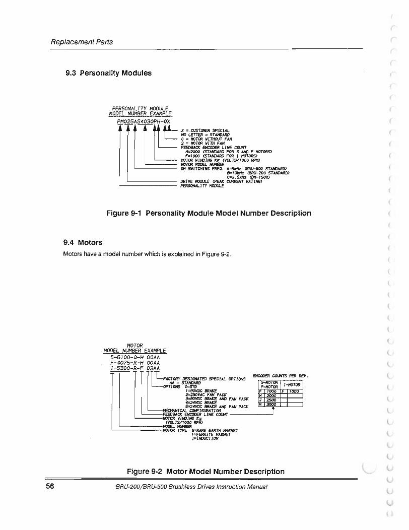
Replacement Parts
56
9.3 Personality Modules
9.4 Motors
PERSONALITY MODULE MODEL NUMBER EXAMPLE
X :: ,CIJSTaEJ! SPECIAL HO LETTER :: STN«JARD 0 :: lfOTOR lllTHOUT FAN 2 :: lfOTOR lllTH FAN FEEDBACX EHCOOER LIHE COWT
11:=2000 CSTAHDARD FOR S N«1 F I'!OTORS> F=1000 CSTAHDARD FOR I I'!OTORS>
I'!OTOR llli«JIHG CVOLTS/1000 RPHJ '----- I'!OTOR l'fOOEL I'UIBER
'------- Dl'f SlllTCHIHG FREQ. A::SkHz CBRU-500 STN«JARD) S=10kflz CBRU-200 STAHDARD) C::2. SkHz
'-------- DRIVE l'fOOll£ CPEAI: CVRRENT RATJHS>
Figure 9-1 Personality Module Model Number Description
Motors have a model number which is explained in Figure 9-2.
MOTOR MODEL NUMBER EXAMPLE
5-6100-Q-H OOAA F-4075-R-H OOAA I-5300-R-F 02AA
FACTORY DESIGNATED SPECIAL OPTJOHS AA :: STANDARD
OPTJOHS 0=511) 1::90VOC 8fW:E
FAN PACX 3=90VOC 8fW:E N«1 FAN PACX 4=24VOC 8fW:E S=24VOC 8fW:E N«1 FAN PACX
EHCOOER COUNTS PER REV.
-t£CHAHlCAL CCWISIRATIOH '----FEEDBACX EHCOOER llHE CCXMT -------'
I'!OTOR llli«JIHS k:E CVOL TS/1 000 RPI'D
L--======fiOOEI.. I'UIBER I'!OTOR TYPE 5=fWIE EARTH I'!AGNET F=FERRITE I'!AGHET 1 = IIIXICTJ OH
Figure 9-2 Motor Model Number Description
BRU-200/ BRU-500 Brushless Drives Instruction Manual
(
(
(
(
(
(
(
(
(
(
(
(
(
{
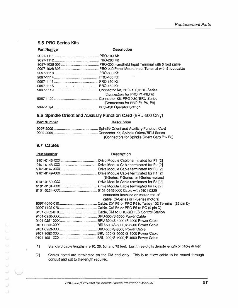
(
r
(
L
Replacement Parts
9.5 PRO-Series Kits Part Number Description
9097-1111 ............................................... PR0-100 Kit 9097-1112 ............................................... PR0-200 Kit 9097-1026-005 ......•................................. PR0-200 Handheld Input Terminal with 5 foot cable 9097-1026-505 ........................................ PR0-200 Panel Mount Input Terminal with 5 foot cable 9097-1113 ............................................... PR0-300 Kit 9097-1114 ............................................... PR0-400 Kit 9097-1115 ............................................... PR0-150 Kit 9097-1116 ............................................... PR0-450 Kit 9097-11 19 ............................................... Connector Kit, PRO-XOO/ BRU-Series
(Connectors for PRO P1-P6,P8) 9097-1120 ............................................... Connector Kit, PRO-X50 /BRU-Series
(Connectors for PRO P1-P6, P8) 9097-1094 ............................................... PR0-450 Operator Station
9.6 Spindle Orient and Auxiliary Function Card (BRU-500 Only) Part Number Description
9097-2000 ............................................... Spindle Orient and Auxiliary Function Card 9097-2009 ................ ............................... Connector Kit, Spindle Orientj BRU-Series
(Connectors for Spindle Orient Card P1- P8)
9.7 Cables
Part Number Description
9101-Q145-XXX ............................ ........... Drive Module Cable terminated for P1 [2] 9101-Q146-XXX ....................................... Drive Module Cable terminated for P2 [2] 9101-Q147-XXX ....................................... Drive Module Cable terminated for P3 [2] 9101-Q149-XXX ....................................... Drive Module Cable terminated for P4 [2]
(S-Series, F-Series, or 1-Series motors) 9101-Q150-XXX ....................................... Drive Module Cable terminated for P5 [2] 9101.0161-XXX ....................................... Drive Module Cable terminated for P6 (2} 9101.0224-XXX ....................................... Cable with 9101-Q329
connector installed on motor end of cable. (S-Series or F-Series motors)
9097-1040-QlO ........................................ Cable, OM P6 or PRO P5 to Tandy 102 Terminal {25 pin D) 9097-1108-Q10 ........................................ Cable, OM P6 or PRO P5 to PC {9 pin D) 9101-Q202-Q10 ........................................ Cable, OM to BRU-SERIES Control Station 9101-Q250-XXX ....................................... BRU-500/S-3000 Power Cable 91 01.0251-XXX ....................................... BRU-500 /S-4000 / F-4000 Power Cable 91 01.0252-XXX ....................................... BRU-500 / S-6000 / F-6000 Power Cable 91 01-Q253-XXX ....................................... BRU-500 / S-8000 Power Cable 9101 -1 080-XXX ....................................... BRU-200 / S-2000 / S-3000 Power Cable 9101-1 081-XXX ....................................... BRU-200 / S-4000 / F-4000 Power Cable
[1] Standard cable lengths are 10, 25, 50, and 75 feet. Last three digits denote length of cable in feet.
[2) Cables noted are terminated on the OM end only. This is to allow cable to be routed through conduit and cut to the length required.
BRU-200/BRU-500 Brushless Drives Instruction Manual 57
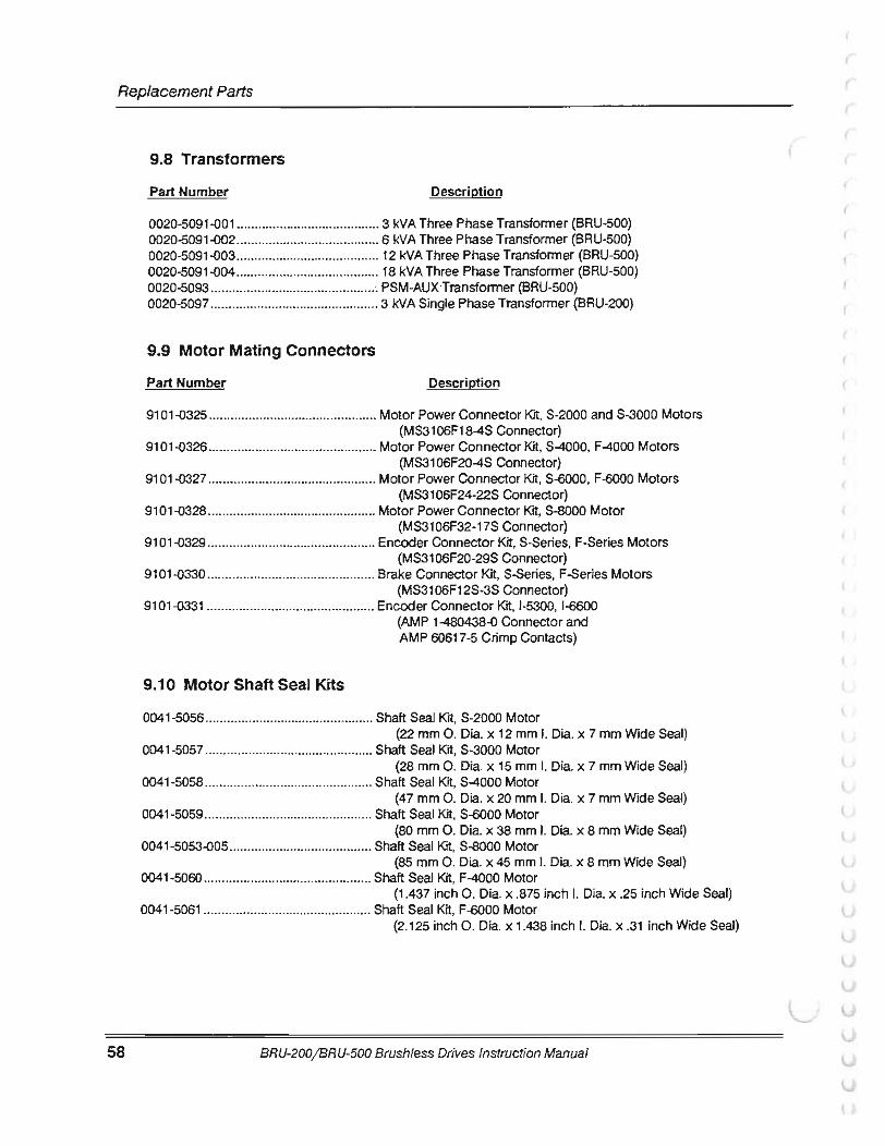
Replacement Parts
58
9.8 Transformers
Part Number Description
0020-5091-o01 ........................................ 3 kVA Three Phase Transformer (BRU-500) 0020-5091-o02 ........................................ 6 kVA Three Phase Transformer (BRU-500) 0020-5091-oos ........................................ 12 kVA Three Phase Transformer (BRU-500) 0020-5091-o04 .............•.......................... 18 kVA Three Phase Transformer (BRU-500) 0020-5093 .................•........................... .-. PSM-AUX·Transfonner (BRU-500) 0020-5097 ............................................... 3 kVA Single Phase Transformer (BRU-200)
9.9 Motor Mating Connectors
Part Number Description
91 01-o325 ...................... ......................... Motor Power Connector Kit, S-2000 and S-3000 Motors (MS31 06F18-4S Connector)
9101-o326 ............................................... Motor Power Connector Kit, S-4000, F-4000 Motors (MS31 06F20-4S Connector)
91 01-o327 ............................................... Motor Power Connector Kit, S-6000, F-6000 Motors (MS3106F24-22S Connector)
9101-o328 ............................................... Motor Power Connector Kit, S-8000 Motor (MS3106F32-17S Connector)
9101-o329 ............................................... Encoder Connector Kit, S-Series. F-Series Motors (MS3106F20-29S Connector)
9101-o330 ............................................... Brake Connector Kit, S-Series, F-Series Motors (MS3106F12S-3S Connector)
91 01-o331 ............................................... Encoder Connector Kit, 1-5300, 1-6600
9.10 Motor Shaft Seal Kits
(AMP 1-480438-o Connector and AMP 60617-5 Crimp Contacts)
0041 -5056 ............................................... Shaft Seal K'rt, S-2000 Motor (22 mm 0. Dia. x 12 mm I. Dia. x 7 mm Wide Seal)
0041-5057 ............................................... Shaft Seal Kit, S-3000 Motor (28 mm 0. Dia. x 15 mm I. Dia. x 7 mm Wide Seal)
0041-5058 ............................................... Shaft Seal Kit, S-4000 Motor (47 mm 0 . Dia. x 20 mm I. Dia. x 7 mm Wide Seal)
0041-5059 ............................................... Shaft Seal Kit, S-6000 Motor (80 mm 0 . Dia. x 38 mm I. Dia. x 8 mm Wide Seal)
0041-5053-o05 ........................................ Shaft Seal Kit, S-8000 Motor (85 mm 0 . Dia. x 45 mm I. Dia. x 8 mm Wide Seal)
0041-5060 ............................................... Shaft Seal Kit, F-4000 Motor (1.437 inch 0. Dia. x .875 inch I. Dia. x .25 inch Wide Seal)
0041-5061 ............................................... Shaft Seal Kit, F-6000 Motor (2.125 inch 0 . Dia. x 1.438 inch I. Dia. x .31 inch Wide Seal)
BRU-200/BRU-500 Brushless Drives Instruction Manual
(
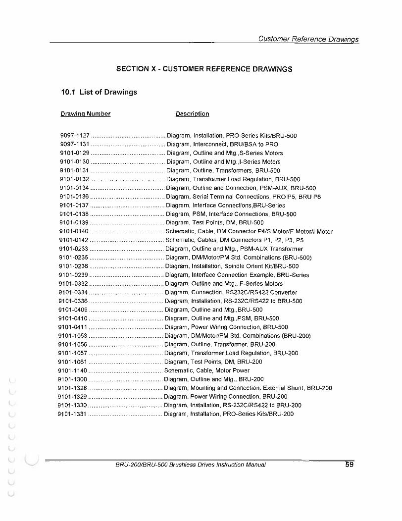
r Customer Reference Drawings
SECTION X - CUSTOMER REFERENCE DRAWINGS
10.1 List of Drawings
Drawing Number Description
9097-1127 ............... .... .. ..................... Diagram, Installation, PRO-Series Kits/BRU-500 9097-1131 ......................................... . Diagram, Interconnect, BRU/BSA to PRO 9101-0129 ..... .... .. ......... .......... .. ....... ... Diagram, Outline and Mtg.,S-Series Motors 9101-0130 .......................................... Diagram, Outline and Mtg., I-Series Motors 9101 -0131 ... ....... ... ... .... ... .... .... ....... .. .. Diagram, Outline, Transformers, BRU-500 9101-0132 .......................................... Diagram, Transformer Load Regulation, BRU-500 9101-0134 ..... ..... .......... ...... ...... .......... Diagram, Outline and Connection, PSM-AUX, BRU-500 9101-0136 ............ .............. ....... ......... Diagram, Serial Terminal Connections, PRO P5, BRU P6 9101-0137 .......................................... Diagram, Interface Connections,BRU-Series 9101-0138 .................. ...... ... ........... .... Diagram, PSM, Interface Connections, BRU-500 9101-0139 ....................... ............. ...... Diagram, Test Points, DM, BRU-500 9101-0140 .. .. ...................................... Schematic, Cable, DM Connector P4/S Motor/F Motor/1 Motor 9101-0142 ...... .... ...... ........... .. .. .. .... .. ... Schematic, Cables, OM Connectors P1 , P2, P3, P5 9101-0233 ................. .. .... .. .. .... ........... Diagram, Outline and Mtg., PSM-AUX Transformer 9101-0235 ..................... ....... .. .. .. ... ..... Diagram, DM/Motor/PM Std. Combinations (BRU-500) 9101-0236 .................... ... ............. ...... Diagram, Installation, Spindle Orient KiUBRU-500 9101-0239 ..... ............. ....... .......... .... ... Diagram, Interface Connection Example, BRU-Series 9101-0332 .......................... .......... .. .... Diagram, Outline and Mtg., F-Series Motors 9101-0334 .... ...................................... Diagram, Connection, RS232C/RS422 Converter 9101-0336 ...... .... .... ....... ..................... Diagram, Installation, RS-232C/RS422 to BRU-500 9101 -0409 ............... .. .. .. .. .. .. ...... .. ....... Diagram, Outline and Mtg. ,BRU-500 9101-0410 .......... .. ..... ....... ... .... ... ........ Diagram, Outline and Mtg.,PSM, BRU-500 9101-0411 .... ... ........... .... .................... Diagram, Power Wiring Connection, BRU-500 9101-1053 ............... ........ ........... ..... ... Diagram, DM/Motor/PM Std. Combinations (BRU-200) 91 01 -1 056 ........... .. ........ ..................... Diagram, Outline, Transformer, BRU-200 9101-1057 .... ............... .. .... .... .. .. ....... .. Diagram, Transformer Load Regulation, BRU-200 9101-1061 ........ ..... .......... ......... .... ...... Diagram, Test Points, DM, BRU-200 91 01-1140 .......................................... Schematic, Cable, Motor Power 9101-1300 .......... ................. .......... ... .. Diagram, Outline and Mtg., BRU-200 9101-1328 ....................... .............. .. ... Diagram, Mounting and Connection, External Shunt, BRU-200 9101-1329 .......................................... Diagram, Power Wiring Connection, BRU-200 9101 -1330 ........... ..... ........ .... .. ............ Diagram, Installation, RS-232C/RS422 to BRU-200 9101-1331 ............................ .............. Diagram, Installation , PRO-Series Kits/BRU-200
BRU-200/BRU-500 Brushless Drives Instruction Manual 59

(
'-
r (
(
(
(
(
(
(
' t l {
\..
l, lJ v lJ;
u u llr l

----- · ..... !$J.! INST
1 . llH!OVE t:OVEfl 0 FROM OP.IVE MODULE . REI·IO'IE tiUTS (tiTY 2. NCT INS JOE OF CO\'EH 0 ANO REMOVE FILLER PANEl. (NOT SHOWII) FAOI·I FRONT OF COVEH .
2 . PLUG RIOBON CAOLE INTO CONNECTOR P7 OF BOARD (£) ANO It/TO CONNECT On PB OF ©.
3 . FASTEN BOAflO @ TO BOARD @ USING (.1) SCREWS ® MID (4) LOCK HASHERS Q) . 4 . PLUG JUW'ER C'.JIIIIECTOR @ WTO COI·II:£r.TOR f'2 OF BOMlO @. 5. PLUG 6 - IHRF. HARNESS ® INTO CONNECTOR P3 OF BOARD @
AND INTO CUNiiECTOR F-4 OF BOARD ©. 6. PLUG 2- HIR£ HARNESS ® INTO f.ClfiNECTOR PI OF UOt.flO @
INTO CONNEf.TOR P6 OF OOARU © . 7 . IN3TALL CCl'•TR 0 .
MATING CONtlF.CTOtlS AilE PROVlOEO IN HIE PfiU- SEniES KIT FOfl CUSTOMEII CUNtlcCi'IOII TO PliO - SERIES CONHIOLLER O'lARU CONNEC:TOilS PI , P2. P3, P5.
T INr. COII•lECTORS At>E PilOV IDEO HIE BRU-500 FOR CUSTOMEI1 CONNECT ION TO BRU-50C LOGIC BOARD CONNECTORS P4, P5. P6 .
.!:19Jf8_
.6\ HAtlNF.SS ® AtiO @ I.RE NOT USED ON ORU- 500 PARI NO'S. 9101-03/X . AilE 1Hi10UGII HiOflON C/.BLF @I
/i':, _l!,l!:_V1Eii
BOARD z BRU- 500 LO:iiC B:JARO
'a) Rli!BON : . - (Hi88m: CAUI.E OE PUSHEO
"\= IU CLF Af1 COVER)
C'lVFR- 7 /;D_ lt'CK HASf!ERS Q) ARE USED ON G Pfl':'-XSOI:J Otll Y.
-------- ·- ---, HRU··500 DRIVE I·:IlH ;
I ON
' JJ3 IP4
_R I GH!.._S l'}l:_ .YJ
Bflll- 5<'0 LOGtr. OOARO ®
PRO-SEillES CONTROL LEn
BOARD
©
_(()!4) @1" .,
.lr5 . ·- (: ____ t t "-JC-:-.... 1
"'''-"'·'!;ffi;· ....... ...... . ,..."41 ... ·'.Y.
CORRECTED
B-cfB-19870, C- 19936
- T--1 RELEASED -
c.,.,,.,.f\,,., ,,,., •• •• .•ntl 'T;'l)_-------Muuv. l '«.tiii,N' E·Jr'l p .. Jl r h . S!.)U 9097-1127
""\ -

(
L
(
(
(
(
(
(
(
". l 1...
l 1...
'-u u u u u u v u l"J
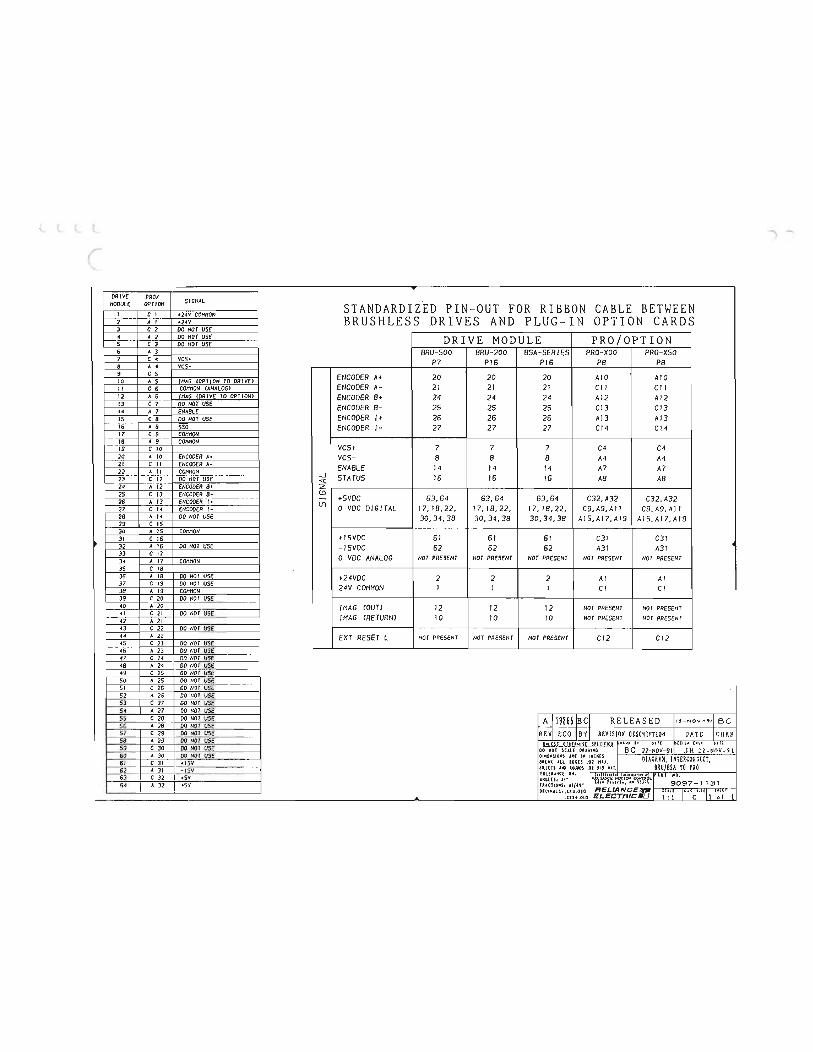
., .....
DRIVE PRO/ SIGNAL MODULE OPTION STANDARDIZED PIN-OUT FOR RIBBON CABLE BETWEEN I C I +14V COMMON BRUSHLESS DRIVES AND PLUG-IN OPTION CARDS 2 A I +24V 3 c 2 DO NOT USE 4 A 2 DO NOT USE DRIVE MODULE PRO/OPTION 5 c 3 DO NOT USE 6 A 3 BRU-500 BRU-200 BSA-SERIES PRO-XOO PRO-X 50 7 c 4 VCS• P7 P16 P16 P8 P8 vcs-8 A 4 9 c s ENCODER A+ 20 20 20 AIO AIO 10 A S I MAG COPT I ON TO DRIVEJ II c 6 COMMON (ANALOG> ENCODER A- 21 21 21 C11 Cl I 11 A 6 !MAG CORIVE TO OPTION> ENCODER B+ 24 24 24 A12 Al2 13 c 7 DO NOT USE ENCODER B- 25 25 25 Cl3 C13 14 A 7 ENABLE 15 c 8 DO NOT USE ENCODER I+ 26 26 26 A13 A13 16 A 8 550 ENCODER 1- 27 27 27 Cf4 C14 17 c 9 18 A 9 ON 19 c 10 VCS+ 7 7 7 C4 C4 20 A 10 ENCODER A• vcs- 8 8 8 A4 A4 21 C II ENCODER A- ENABLE 14 14 14 A7 A7 11 A II COMMON 23 c 11 00 NOT USE
__J STATUS 16 16 16 A8 A8 .q; 14 A 12 ENCODER 8• z 25 c 13 ENCODER 8- (!)
63,64 26 A 13 ENCODER I+ - +SVDC 63,64 63,64 C32,A32 C32,A32 lf)
27 c 14 ENCODER 1- 0 VDC DIGITAL 17, 18,22, 17, 18, 22, 17, 18, 22, C9, A9,A11 C9. A9, AI 1 28 A 14 DO NOT USE 30,34,38 30,34,38 30,34,38 AIS,A17,AI9 AIS,AI7,A19 29 c 15 30 A 15 COMMON 31 c 16 +ISVDC 61 61 61 C31 C31 32 A 16 DO NOT USE -ISVDC 62 62 62 A31 A31 33 c 17 0 VDC ANALOG NOT PRESENT NOT PRESENT NOT PRESENT NOT PRESENT NOT PRESENT 34 A 17 CONNON 3S c 18 36 A 18 DO NOT USE +24VDC 2 2 2 AI AI 37 c 19 DO NOT USE 24V COMMON I I I Cl Cl 38 A 19 COMMON 39 c 20 DO NOT USE 40 A 10 IMAG COUTJ 12 12 12 NOT PRESENT NOT PRESENT 41 c 11 00 NOT USE IMAG CRETURN) 10 10 10 NOT PRESENT NOT PRESENT 41 A 21 43 c 11 DO NOT USE 44 A 11 EXT RESET L NOT PRESENT NOT PRESENT NOT PRESENT Cl2 C12 45 c 13 00 NOT USE 46 A 23 00 riOT USE 47 c 24 DO NOT USE 48 A 24 DO NOT USE 49 c 25 DO NOT USE 50 A 25 DO NOT USc 51 c 25 00 NOT USE 52 A 2o DO NOT USE 53 c 27 00 NOT USE 54 A 27 00 NOT VSE 55 c 28 00 NOT USE A lt9866 lscl RELEASED "-NOV-'011 B c 56 A 18 00 NOT USE
REvr ECO ls vl REVISIOH OESCRIPTIOH !cur.R 57 c 19 00 NOT USE DATE 58 A 13 00 NOT USE !!!!l.!.!S OIK{RWISt SP(CIFI!O UVII It U .... ,,., .. ' 59 c 30 DO NOT USE DO SCAlE DUWING BC 22-NOV-91 JH n-NOV-91 60 A 30 DO NOT USE DIHUSIONS U£ IN INCHES DIACRAH, mERCOtliiECT, 61 c 31 +I SV eREU All EDGES .D1 HU.
1--·F A 31 - ISV FlllE IS AND .01 UD HAl. BRU/BSA TO PRO ON, J "1 " ' " u mool", ,rAR; HO . 63 C32 +SV AHGLES 1 tl• '"fl'U.."'CE tOT10H
I A32 +S'I FIACIIONSo ti/U' "h•lfl•, HI II " 9097-1 1 31 DECIMALS· .lU.DlO RELIANCEJI!J I " 1°" s: 'I "'" ...... ,lllt.OID ELECTRIC U t: t C 1 of 1

(
(
(
(
(
(
(
(
{
\.. !,._
l l L L v v Lv v
Lr U u u u tJ
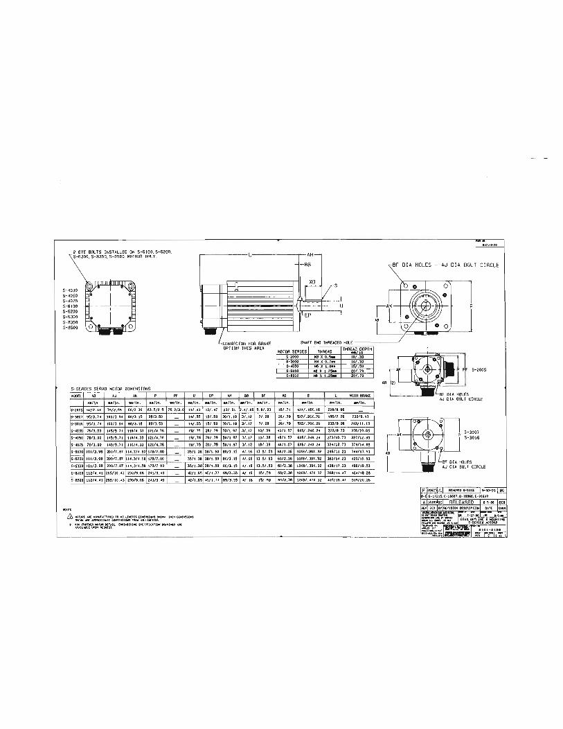
2 EYE BOLTS INSTALLED ON S-6100, S-6200. S-6300,S-B350, S-8500 MOTORS ONLY.
S-4030 S- 4050 S-4075 S-6100 S-6200 S-6300 S-8350 S-8500
S-SERIES SERVO MOTOR DIMENSIONS HODEL A8 AJ AK p
u/ln . ••lsn. """"· ao/ln.
S- 2005 62/2 .44 75/2 .95 60/2 .36 63 .5/2 .5 S-3007 95/3 . 7• 100/3.94 80/3 . 15 89/3.50
S- 3016 95/ 3. H 100/3.94 80/3 . 15 89/3 .50 5- •o3o 76/ 3 .00 t•5/5. 71 110/ • .33 12t/• . 76 S- 4050 76/ 3.00 145/5 .71 110/ 4.33 121/4 .76
S- 4075 76/ 3. 00 145/ 5 .71 110/ 4. 33 1211• . 76 5-6100 101/ 3 . 98 200/7 ,87 114.3/ 4.50 178/7 .00
5-6200 101/3 .98 200/7 .87 114.3/4 .50 17817 .00
S-6300 101/3 .98 200/7.87 114.3/ • . 50 178/7 .00
5- 8350 11214. •1 265/ 10 . 43 230/9 .06 2•1/9.49 S- 8500 112/4.41 265/ 10.43 230/ 9 .06 241/9 . 49
NOT£!:
Pf
ao/!n. 76.2/3.0
---
-----
:
u N / !n .
11/ . • 3
1•1.55 14/.55 19/.75 19/ .75
19/ .75 35/1.38
35/1.38
35/1 .38 .2/1.65 42/1.65
& tetOAS ot.AE MNIJr.CJ\MED TO MIU.IN£1[A OIMEH'SIOHS SHOVH. lt<H OIMENSIOtl! SHOIIIH Al't APPROXIMAl£ COtiVWIOHS fROM MllllMElEAS.
2' . ")A IU'Tl£A MOIOit OETAtL Oft1NE£R1M8 S'P£CIF'ICUIOH DRAWING! A.A£ AVAIU8l.E At:MST .
-EP
ao/ln . 12/ . • 7
!5/ .59 15/ .59 20/ .79 20/ . 79 20/ ,79
38/ t. 50
38/1.50
38/1.50
77 45/1.77
L
-il-
CONNECTOR FOR BRAKE OPTION THIS AREA
AH 88 8f
M/ln. M/ln. u / !n .
23/.91 2 . • /.09 5.8/.23
30/1 . 18 3/.12 7/.28
30/t. 18 3/ . 12 7/.28
50/1.97 3/ . 12 10/ .39 50/1.97 3/ . 12 10/ .39
50/1.97 3/. 12 10/ .39 80/3.15 4/. 16 13. 5/.53
80/3.15 ./. 16 13 .5/.53
80/3 . 15 ./.16 13 .5/.53
85/3 .35 16 15/ .59 85/3.35 ./ . 16 15/. 59
1101-fiH
AH-- -BB BF OIA HOLES - AJ OIA BOLT CIRCLE
.,t vs, - -r-- --f- L u p
1tEP I
HOLE -------J MOTOR SERIES THAEAO THRE,e.D;PlPTH
S-2000 H3 X O.!IM 10/. 39 S-3000 H. X 0. 7H 10/ .39 s-•ooo M6 X ! .OM 15/ .59 S-6000 H8 X t .25M 20/.79 S-8000 M8 X !.25M 20/. 79
XD s l BRAKE
N / ln . oo/tn. oo/ !n. ao/ln. 18/. 71 •ul. 16X. 16 228/ 8.96 -20/ .79 5X5/ . 20X . 20 185/7.26 232/9 . 13 20/ .79 5X5/. 20X . 20 235/ 9 .26 283/ 11 . 13 •ot t. 57 6X6/ . 24X . 2• 222/ 8.73 276/ 10.85
•ot t." 6X6/. 24X. 24 273/10.73 327/ 12. 85 40/ 1.57 6X6/. 2•X. 24 32./ 12. 73 60/ 2.36 IOX8/. 39X .32 286/ 11 .23 344/ 13 .53
60/2.36 IOX8/ . 39X . 32 .20/16 .53 60/2.36 IOX8/.39X .32 438/17 .23 496/19.53
60/2.36 12X8/ . • 7X. 32 368/ 14 . • 7 464/18.26 60/ 2 .36 12X8/ . • 7X .32 419/ 16 .47 5!5/ 20.26
AB
S-2005
S-3007 S-3016
1 -,

(
(
("
(
(
(
(
(
(
(
(
\
(
(
t l
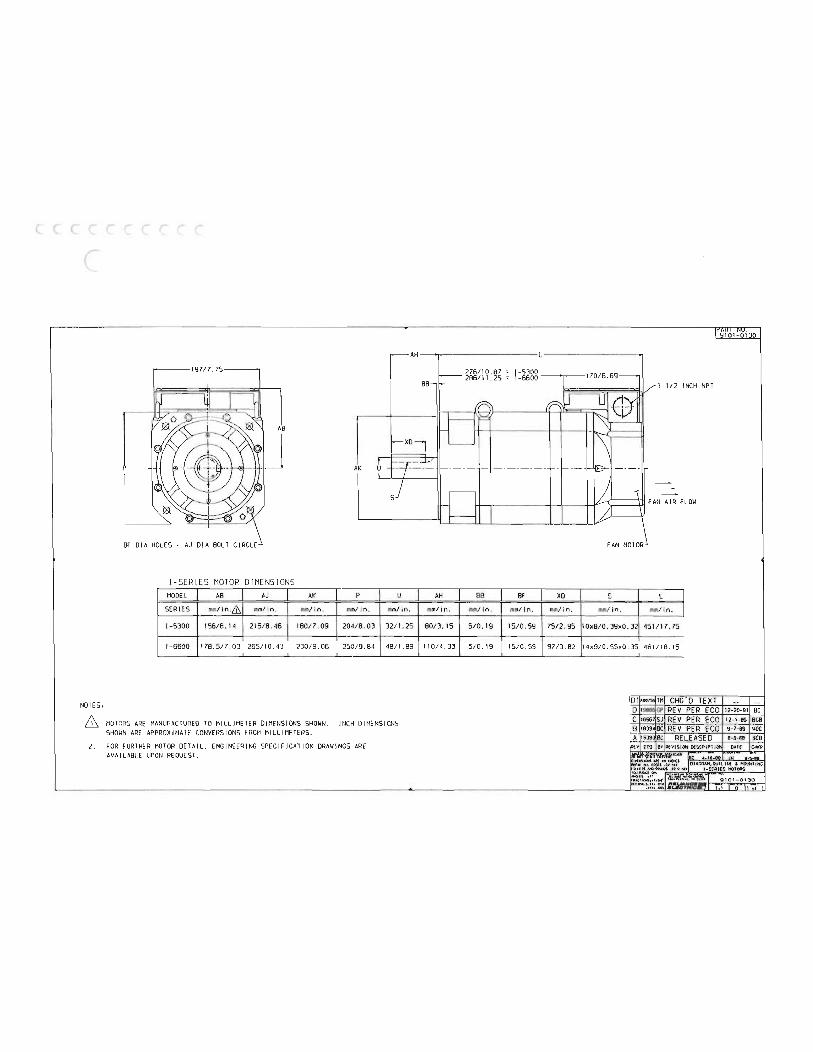
AH r-------1 97/7. 75----·
AB
J AK
BF DIA HOLES- AJ DIA BOLT CIRCLE
I-SERIES MOTOR DIMENS IONS MODEL AB AJ AK p u
SER IES mm/in.& mm/in. mm/in. mm/in. mm/in.
1- 5300 156/6.14 215/8.46 180/7.09 204/8.03 32/1. 25
1-6600 178.517.03 265/10.43 230/9.06 250/9.84 48/1.89 - - -- ---
NOTES,
MOTORS ARE MANUFACTURED TO MILLIMETER DIMENSIONS SHOWN. INCH DIMENSIONS SHOWN ARE APPROX IMATE CONVERS IONS FROM MILLIMETE RS.
2. FOR FURTHER MOTOR DETAIL, ENG INEERING SPECIFICAT ION DRAWI NGS ARE AVAILABLE UPON REQUEST.
I - -....--1 1/2 INCH NPT
AH BB BF XD s L I mm/in. mm/in. mm/in. mm/in. mm/ in. mm/in.
'
B0/3. 15 5/0. 19 15/0.59 7S/2.95 10x8/0.39x0.32 451/17. 75
110/4.33 5/0. 19 15/0.59 9713.82 14x9/0.55x0.35 461/18.15 ------ - ------
D CHG" D TEXT GP REV PER ECO
c 18667 SJ REV PER ECO B BC REV PER ECO A 16JB BC RELEASED
IPEV ECO 8Y REV ISI ON DESCPIPlJON
"'\
12-20-91 BC 12- 1-89 BCB 9- 7-89 woe 8 -5-88 BCB
DAlE CHI:P

r (
(
(
( (
(
(
(
(
(
l l (
l \ {.
l L 0 l u l;i
u v
L u u u u

NOT£5,
& &
& S£COND.<Rl
&
0, CRCl.H) SIUO tlAANSf()QrtfA CtiASSISJ
0
F mJ-o .o.o6__j
CO!f<£C1 JO/f INSTIIUCT JOHS
{ 8.0 HIN tl£AA AHCE O£COitltENOEO fOR ACC£SS 10 WIRING
C H.O
1.--------A
OIHC OQ 5PA0£ LUG CONH£t10RS (NOT AO£ llfOUI0£0 fOQ COHN£C110HS TO IOAIISfOOitEO T[OHINAL SIOIPS. l[OHINAL STOlP SC0£11 511£5 ARE liSTED HI lHf OIH.(NSJON CtiART .
US£ LUCS Ol'SICN£0 f OQ 16 SCRf W "0\.tlll t+G.
In£} lANCE MOTION COHIII<ll. lA,t.NSf OAI'EA PART NO.
0020-5091·001 0010·5091 · 002 0020-5091·00) 0020-5091-004
KVA OVERALL DIMENSIONS RAt lNG A 8 c
J 6.50 9.50 6 15.25 6.50 12.50 12 15.25 B.SO 1).25 18 22.50 9.00 18. 25
) -.
-
9101·01)1
C RH
0.56 10.03 OIA lHRU (-4)
MOUNTING HOLES LOCAliON SCREII SIZES ..1\. 0 E F G PR I MARV Jse CONOARV
s.so ).50 1,15 /I:, I 6·J2 10.50 3 . 78 2. Jll l.J6 6-J2 B·J2 10.50 5.90 2. Jll 1.30 6- 32 10-32 16. 00 5. J8 J .2S 1.81 B·JZ 10·J2

(
L
r (
(
(
(
(
(
(
(
{
t l \ l t L:,
\..;!
v v v (
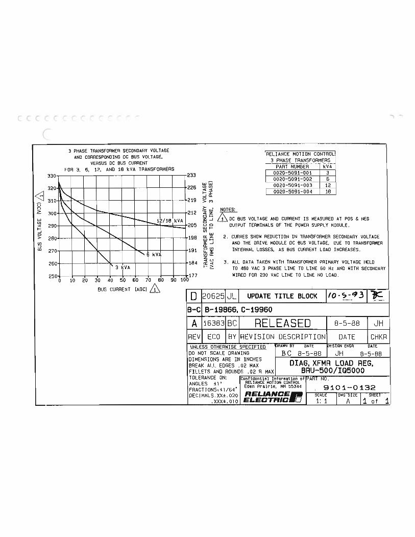
l......,
3 PHASE TRANSFORMER SECONDARY VOLTAGE AND CORRESPONDING DC BUS VOLTAGE, RELIANCE MOTION CONTROL
VERSUS DC BUS CURRENT 3 PHASE TRANSFORMERS FOR 3, 6, 12. AND 18 kVA TRANSFORMERS PART NUMBER kVA
330 233 0020-5091-001 3
w@ 0020-5091-002 6
320 226 l!)tf) 0020-5091-003 12 0020-5091-004 18 1-:I: <8 310 219
..JQ. 0
g ""'->m >- •
300 \ ...__ -- 212 O:UJ NOTES:
lli \ "'-........... 1'--- --........._1 )/18 kVA & DC BUS VOLT AGE AND CURRENT IS MEASURED AT POS & NEG
290 " - 205 uo OUTPUT TERMINALS OF THE POWER SUPPLY MODULE . UJ ..... tl1
UJ 280 ......... ""' 198 a:z 2. CURVES SHOW REDUCTION IN TRANSFORMER SECONDARY VOLTAGE
270 " "' 191
UJ H ::::£...1 AND THE DRIVE MODULE DC BUS VOLTAGE, DUE TO TRANSFORMER a: 0 tl1 INTERNAL LOSSES. AS BUS CURRENT LOAD INCREASES .
"' " kV, U..::::£ tna: z
3. ALL DATA TAKEN WITH TRANSFORMER PRIMARY VOLTAGE HELD 260 I' 184 3 kVA TO 480 VAC 3 PHASE LINE TO LINE 60 Hz AND WITH SECONDARY 250 l 177 WIRED FOR 230 VAC LINE TO LINE NO LOAD.
0 10 20 30 40 50 60 70 80 90 100
BUS CURRENT (ADC) & 0 20625 JL UPDATE TITLE BLOCK to-c,-q3
8-C B-19866,C-19960 A 16383 BC RELEASED 8-5-88 JH
REV ECO BY REVISION DESCRIPTION DATE CHKR UNLESS OTHERWISE SPECIFIED PRAHN BY DATE DESIGN ENGA DATE
DO NOT SCALE DRAWING BC 8- 5- 88 JH 8- 5- 88 DIMENSIONS ARE IN INCHES DIAG,XFMR LOAD REG, BREAK ALL EDGES . 02 MAX FILLETS AND ROUNDS .02 A MAX BRU-500/IQ5000 TOLERANCE ON: Confidential Information of IPART NO . ANGLES ±1· RELIANCE MOTION CONTROL FRACTIONS dl /64. Eden Prairie, MN 55344 9101-0132 DECIMALS.XX± . 020 FIELIANCEI!j SCALE I DWG STIE 1 SHEET
.XXX±.OlO ELECTRIC D 1: 1 A 1 of 1

(
l.,f
(
(
(
(
(
(
(
(
(
(
(
(
l l
(.,
\I 0 Ll l,
G VI u u u (J
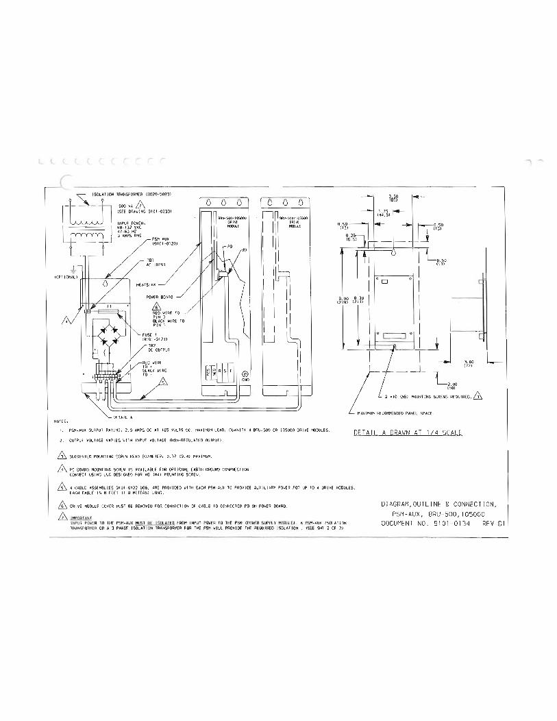
( ______________ __ ION TRANSfORMER (0020-S093J
dl SOOVA& <SEE ORAIIJNC 9101-0233)
INPUT POWER• 88-132 VAC 47-63 HZ 3 AMPS RMS
(OPT IONALJ riff _r / ,
PSH-AUX (9101-0120)
TBI AC INPUT
ffi REO WIRE TO PIN 3 BLACK IIIRE TO PIN 1
182 DC OUTPUT
s
0 0 0 n BRU-S00/ 105000 II ORIV£ II
·J9
E1WJ @ GND
0 0 0 n BA\1-SOOIIOSOOO
I Iii =E I Iii I Iii I I I 1 I I II I I II I I u l
II
fl 0 1 '--0. 50
(1))
I I OD 0 I c I
9 oo e. 38 I <229> (21)) I I
0 I J c 'j__j I ).00 L
(77) _ _jL 2.00 (50J
MOUNT ING SCREWS
DETA IL A MINIMUM RECOHHENDED PANEL SPACE . NOTES,
I . PSM-AUX OUTPUT RAT ING, 2.0 AMPS DC AT 16S VOLTS DC. MAXIMUM LOAD, OUANIT Y 4 BRU-SOO OR 105000 DRIVE MODULES.
2. OUTPUT VOLTAGE VARIES INPUT VOLTAGE (NON-REGULATED OUTPUll. DETAIL A DRAWN AT 1/4 SCALE
& SUGGESTED MOUNT ING SCREW HEAD DIAMETER, 0 . 37 C9 . 4J MAXIMUM .
& PC BOARD HOUNT lNG SCREW IS AVAILABLE FOR OPTIONAL EARTH GROUND CONHNECT ION . CONNECT USING LUG DESIGNED fOR •6 <M4J MOUNTING SCREW.
4 CABLE ASSEMBL IES 9101 -0122- 006, ARE PROV IDED IIITH EACH PSH-AUX TO PROVIDE AUXI LIARY POIIER FOR UP TO 4 DRIVE MODULES. EACH CABLE IS 6 FEET (1 .8 HETERSJ LONG.
ffi DRIVE MODULE COVER MUST BE REMOVEO FOR CONNECTION OF CABLE TO CONNECTOR P9 ON POIIER BOARD.
£ IMPORTANT INPUT POWER TO THE PSM-AUX MUST BE ISOLATED FROM INPUT POWER TO THE PSM SUPPLY MODULE). A PSH-AUX ISOLATION TRANSFORMER OR A 3 PHASE ISOLATION TRANSFORMER FOR THE PSM II ILL PROVIDE THE REQUIRED ISOLAT ION. <SEE SHT 2 OF 2J
DIAGRAM,OUTLI NE & CONNECTION, PSM-AUX, BRU-500, 105000
DOCUMENT NO. 9101-0134 REV 01
""' .....

(
r (
(
(
(
(
(
(
(
(
(
(
(
l
(
(.
(.
(.
l (.
L
L u
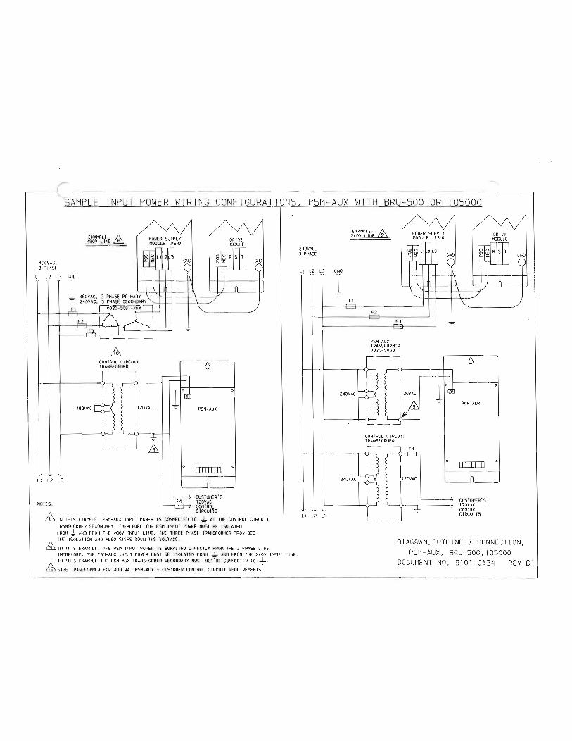
r ..-----
SAMPLE INPUT POWER WIRING CONFIGURAT ipNS, PSM-AUX WITH BRU-500 OR !05000
480VAC, 3 PHASE
L1 L2 L3 GND
I -=-
EXAMPLE, 480V LINE LB
M:, CONTROL CIRCU IT TRANSFORMER
480VAC
Ll L2 l3
NOTES,
-=-
ffi 0
F4
0
PSM-AUX
111111111
CUSTOMER'S 120VAC CONTROL
0
0
CIRCU ITS ffi IN THI S EXAMPLE, PSM-AUX INPUT IS CONNECTED TO THE CONTROL CIRCUIT TRANSFORMER SECONDARY. THEREF ORE THE PSM INPUT POWE R MUST BE ISOLATED
AND FROM THE 480V INPUT LINE. THE THREE PHASE TRANSFORMER PROVIDES THE ISOLATION AND ALSO STEPS DOWN THE VOLTAGE.
THIS EXAMPLE, THE PSM INPUT POWER IS SUPPLIED DIRECTLY FROM THE 3 PHASE LINE. THEREFORE , THE PSH-AUX INPUT POWER MUST BE ISOLATED FROM _I_ AND FJlOH THE 240V INPUT LINE. IN THIS EXAMPLE THE PSM- AUX TRANSFORMER SECONDARY MUST CONNECTED TO _1_,
Ms1zE TRANSFORMER FOR 4oo vA cusTOMER coNTROL CIRCU IT
240VAC, 3 PHASE
EXAMPLE, 240V LINE 9
L1 L2 L3 GND
I -=-
F 1
240VAC
240VAC
L 1 L2 L3
F2
PSM-AUX TRANSFORMER 0020-5093
r 1120VAC
I
I /g\ I
CONTROL CIRCU IT TRANSFORMER
1120VAC
I
-=-
-=-
111 """I
0
0
PSM-AUX
IIIIITTD
CUSTOMER'S 120VAC CONTROL CIRCU ITS
0
0
DIAGRAM,OUTLINE & CONNECTION, PSM-AUX, BRU-500, IQSOOO
DOCUMENT NO. 9101-0134 REV 01
1 -.

(
(
(
( ( (
(
(
(
(
(
(
(
(
(
(
(
u
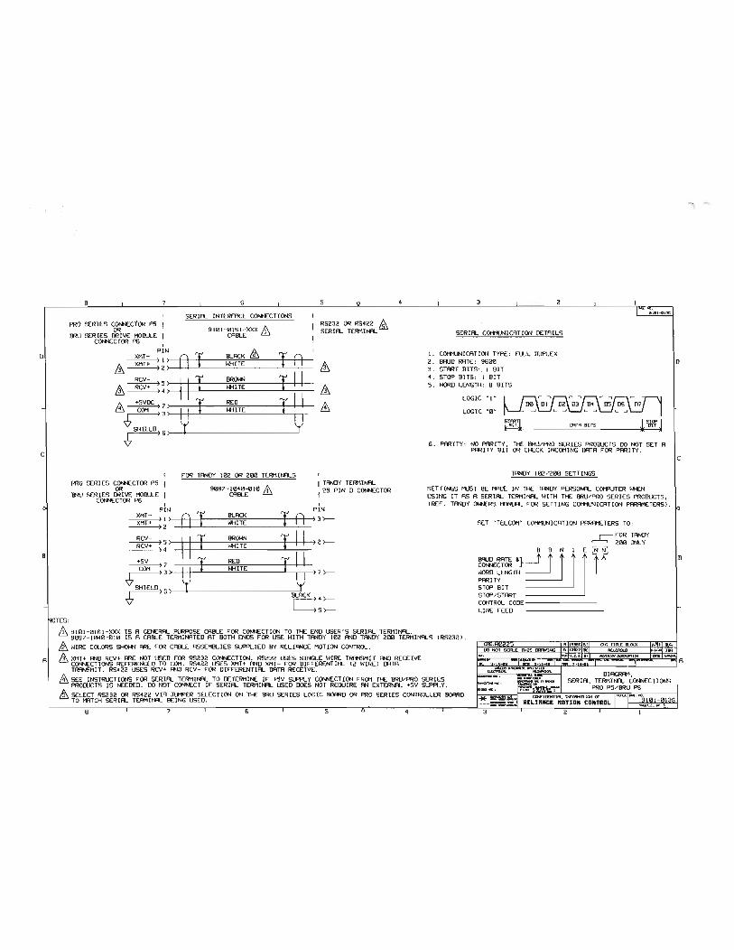
D
c
B
A
8
PRO SERIES COf\NECTOR P5 OR
I3RU SERIES DRIVE HODU...E PS
7
I XMT- PIN
6
SERIAL INTERrACE CONNECTIONS
9101-0161-XXX "' CABLE ill
5
RS232 OR RS422 SERIAL TERMII'R...
" 3 2
SERIAL COMMUNICATION DETAILS
I. COMMUNI CATION TYPE: tULL DUPLEX &. A I & I A &. 2. BAUD RATE: 9600 I D
·TES:
RCV- I & II = I II /).. +5VDC I
COM : :: I I = I ! ! SHIELD 'l
)6) y
PRO SERIES CDI'K:CTOR PS OR
BRU SERIES DRIVE MOILLE COI'l'IECTOR PS
tOR TANDY 102 OR 200 TERMINALS
9097-1040-010 "' CABLE ill
I
&. &
I TANDY TERMINAL I 25 PIN D COI'l'IECTOR
I PIN 1 XMT- B I PIN XMT+ ) I ) BLACK I A WHITE ) 3>--
:;' II I = I II m-+ RED +!! COM ) ) I I *liTE ) 7>--
SHIELD) 6 ) 'l y jACK: 4 >--
5 >--
3. STMT BITS: . I BIT 4 . STOP BITS: I BIT 5. WORD LENGTH: 8 BITS
LOGIC " I "
LOGIC "0" ! STCP J BIT IJ'lTR BITS BIT
G. PAUTY : NO PMITY, THE BRU/PRO SERIES PRODUCTS DO NOT SET A PMITY BIT OR CHECK INCOMING DATA tOR PARITY .
TANDY 102/200 SETTINGS
SETTINGS MUST BE MADE IN THE TANDY PERSONAL COMPUTER WHEN USING IT AS A SERIAL TERMINAL WITH THE BRU/ PRO SERIES PRODUCTS, <REt. TANDY OWNERS MANUAL t OR SETTING COMMUNICATION PARAMETERS>.
SET "TELCOM" COMMUNICATION PARAMETERS TO: r-tOR TANDY
,__._, 200 ONLY
t t 8 N I E
WORD LENGTH PARITY STOP BIT STOP/START CONTROL CODE-------_! LINE tEED
/19101 - 0161 - XXX IS A GENERAL PURPOSE CABLE tOR CONNECTION TO THE END USER' S SERIAL TERMINAL. 9097- 1040-010 IS A CABLE TERMINATED AT BOTH ENDS tOR USE WITH TANDY 102 AND TANDY 200 TERMINALS <RS232l. & WIRE COLORS 5HOW'I ARE tOR CABLE ASSEMBLIES SlJ'PI...IED BY RELIANCE MOTION CONTROL.
/i XMT+ AND RCV+ ARE NOT USED tOR RS232 COIINECTION. RS232 USES SINGLE WIRE TRANSMIT AND RECEIVE CONNECTIONS REtERENCED TO COM . RS422 USES XMT+ AND XMT- tOR DittERENTIAL <2 WIRE) DATA TRANSMIT. RS422 USES RCV+ AND RCV- tOR DlttERENTIAL DATA RECEIVE . & SEE INSTRUCTIONS f'OR SERIAL TERMINAL TO DETERMINE If' +5V SLf'PL Y C<»>ECTION tROM THE BRU/PRO SERIES PRODUCTS IS NEEDED. DO NOT CONNECT It SERIAL TERMINAL USED DOES NOT REQUIRE AN EXTERNAL +SV SUPPLY . SELECT RS232 OR RS422 VIA JUMPER SELECTION ON THE BRU SERIES LOGIC BOARD OR PRO SERIES CONTROLLER BOARD TO MATCH SERIAL TERMINAL BEING USED.
8 I 7 I 6 I 5 Q 4 3
9 h996GISJ I <Hi TlllL a.OO<
CXH'lDINWl. liFOIHnlON or RELIANCE ftOTION CONTROL
2
c
B
""\ ....

(
(
(
( (
(
(
(
(
(
l l l l l l l lv G 0 0 u v
L u lti u u {
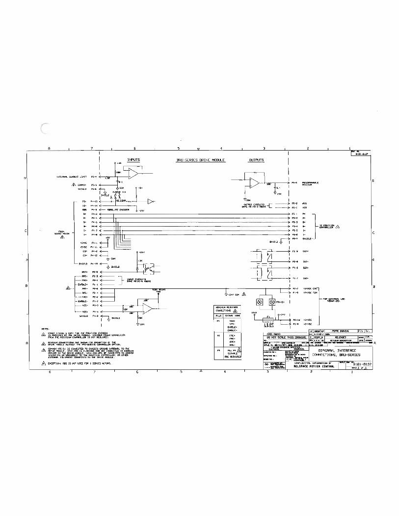
01
c
B
A
8
EXTIJNt.. Cl..R*:NT L 1111 T
,._ SOIYO 110TOA
&,.
C(H1(H
SHID.D
TS+
T5-fiBS
R+ ,._ .. Il-l+
1-
+5\IDC +5\IDC
C01
C01
7 6 I I
INPUTS .... I I
1'5 ....
1'5-S
1'5-6
P4- 13
P1 - J1
P<- 9 <E---P1 - l P1 - 4
P1- 5
P<-6
P4-7 ...., ...... ( +5Y
PH :=::1 P1- U
P<-2 P1- 12 CQ1
+24V
151< SHID.D
RST+
1¥1C+
rAC+
P4- 10 SHID.D
PZ-9
&,. RST-
PZ- 3 <E-------PZ- 1 <E-------PI- 1 <E-----PZ-9
RAC- PZ- 1 a rAC- PZ-2
P l- 2
} Jtfl.JT CIROJITS !R£ AS PZ-5 ftiOIIE
vcs- Pl-3 ( I I I 1/CS+ Pl.... ( I ,:.t) I I
6HIIl.D Pt-' n SHID.D
I NOTESo
&
£
PCH:R ( •SVDC ' CQ1) r OR TK POSIT lc:».a OCOIJ[R IS PAOIIIIXD flY 1K IIU\'t 11011.U:. OCODER PO£R CON:CTIOII fliQ1 1K POSIT CONTRO.I.£R IS NOT AECJJIOED.
"1Hltu1 ca-H:CTI<Ni fAt Stt::Hi f'OR CPEJIWUlc:tf fX Tl€ t10Cl.LI: Hln«::UT TK PAO-SERJCS CQ<ITRa..UR CPTION.
COt10II IPS- 5 I IS CON:CTED TO OR;SIS Q!CI.Nl INTtiN\. TO 1K (JIJVE tal..l.£ , +24V COI1 JS n..CJrrJJ.G FNl NOT CON:CTtD TO OAS'SIS Ql(lN) IN TK: IRI\'t 1101U.£, +21Y C01lfl'l 8£ CON:CTED TO CCH1CH (f\.ORTlt..c M CACI.HGJ lH n£ POSITJCH COH1RCJ...1..DI. CR OTKR OITIRR. tCJJIPtC<T CON:CTED TO 1K IRI\'t 110111.£.
8 DICD'TIC»>o ADS IS NOT lSD r OA 1- SOIICS 110TOIIS.
8 7 6
CMI
5 4 3 2
BRU-SERIES DRIVE MOill.LE OUTPUTS
1'5-3 I'R<lOfRHUl.£ -I TOR
OUTl'UT CIRQIITS -c 1'5- 2 1M)
SR1E AS 1'5- 3 ftiOIIE PS- I HCO
P3- l }=& P3-2
P3- 3
P3 ....
P3-$ I+
P3-6 1-
n P3-7 SHID.D SHID.D
]8 I
) PZ-9 ruT+ I I
) PZ-9 ruT-
]8 ) Pl-6 550+ I I
) Pl-7 sso-I
PZ- 7 t24VDC - - -
+21Y COlt £ I
"INIIU1 AECJJIOED CON:CTIONS £ f'UJG SIQR. 1ft'£
PI IICS+ vcs-
Oflll...[+ Oflll...[-
PZ rAC+ me-1¥1C+ RAC-
P1 fU P<_& SIQft.S
fR: AECJJIRIJ
5 4 3
n-oe PHI
+24YDC
+2<tVDC
2
rOA COI:Roft. U1E ·--·
1
D
l c
I .B

(
(
(
(
(
(
(
(
(
(
(.
<..
l (._
c, l \.. l_y
lY v
L u u (;,
u ' I

NOTES:
(
SAMPLE EXTERNAL CONNECTIONS
--81 I 4Jv I I 2 I I COM L _ ____ _
,-----1 _ p-:;"1 I I I I L 'tot" -[d I
i rc, ,,-==]- r,Jl I+V _ I
I - L--0 L - - ___f.QM_- _
2 J
L- 81
1. +24V AND +24V COM SUPPLY CONNECTIONS ARE AVAILABLE FROM THE DRIVE MODULE, CONNECTORS Pl OR P2 .
POWER SUPPLY MODUL-E
STATUS- . I , r=-. ff I
2 I STATUS• l EXTERNAL ENABLE INPUT
1. SK OHM
I I
NO I CONN I
ll o.s wAn sty 1 L ______ JUMPER w1j
D 11A00751ITM REDRAW B-01 19866, 19960 I 20625
A I16383IBCI RELEASED
UNLESS SPEC IFIED DO NOT SCALE DIMENSIONS ARE IN INCHES
JH
BREAKALLEDGES.02MAX DIAGRAM, PSM, I NTERFACE FILLETS AND ROUNDS .02 R MAXCONNECT IONS, BRU-500/ I QSOOO TOLERANCE ON, con f ldOi"t•ol lnloroouon of ANGLES ± 1 • RELIANCE HOT ION CONTROL FRACTJONS,tl/64. E<loi" Proirie, MN I 9 1 01 -01 38 DECIMALS. XX± .OlO REl-IANCE- StALE JUwG sm 1 SRI'
.xxx±.oos El-ECTR/c•o
""\ ......

(
L
r (
(
(
(
(
{
{
(._
t...
c.... <...:,
v G lJ,
v u v v u (
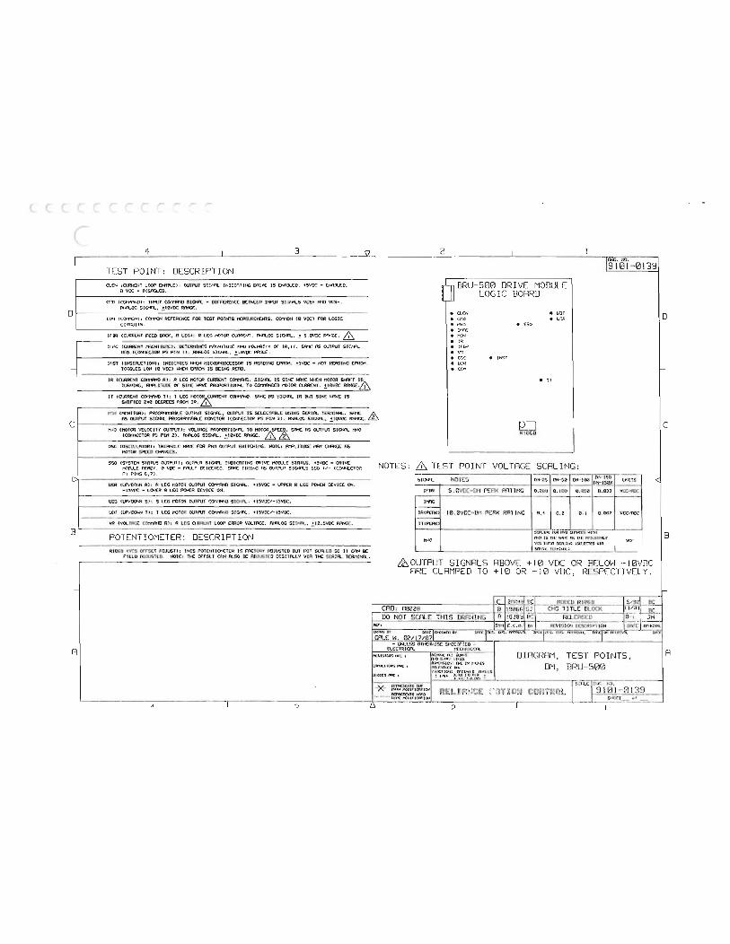
D
c
.....
B
-
A
"1 3 \l ______ _ 2 ·-TEST POINT: DESCRIPTION CU:N IC\.RI<CIIT LOOP INIIl.O: OJTI'\IT SIG.'R. MIV( IS ENRil.CO. 45VOC • ENRil.EO,
0 VDC • OISRELEO.
CttO !!fliT COt'rl\'ID S I C!fl. • OtrrERENCE OCTI<CN HP.JT SI.;t>'\.S VCS+ AND VCS-, FY<R..OG 10VDC Rrnef..
CCI1 ICOI"MMNl: COifllN RErERCNCC rOR TEST POINTS 11CRSUlCI1£NTS. c=ION HI VDC) rOR LOGIC CIRCUITS.
trOR IQAA£NT rEEO BRO<, R LEG!: R LEG MOTOR CU'lR(NT. F»l.OG SIGNAL, 5.01/DC Rf\':GE. & H11G CC.-ENT t'AGNIT\JOC): DETERr11NES W>".NITUOC AND PO-M!TY Of" IR, IT. SRt1C RS OUTPUT SIC'R..
NCO ICOI'I'ICCTOR PS PIN I l . ANALOG S IGNR., RR:lGC.
H:ST <INSTRUCTION!: INDICATES 1·0-ICN HICROFROCESSOR IS RtADING EPROM. +5VDC • NOT READI NG EPROM. l O.-:G..CS LOW 10 VOCl EPROM IS BEING R!:AD.
IR lamENT E=R"D Rl: R LCC HOTOR CLRR!:NT C00"\'1'<'10. SIGI'R. IS SINE 141CN MOTOR SI«T TIHIING, R"'PI.ITUOC 01" PROPORTIO.>-t. TO MOTOR CLRR!:NT. RIWCE. I
IT COJlRENT COt'l"'A'ID T l: T LEC t!OT&URR!:NT CO.rA-10. Sf'<'£ AS SIG.'«. !R lll1T SINE >$IV[ I S SHirT EO Z40 OCCR!:ES rROM IR. I
DRIVE MODULE
• c e CMD " MVO • l<"fl :; • mN
• • • • • •
LOGI C
e INST
BOARD
" LIDT • UDS
• 550
e IT
9 101-0139
WlN CMC«ITORl: f'ROG'li..-ABLE OUTf'UT SIGin.. , OJTNT IS SELECTABLE lfjiNG SERIAL Sff"t: J. .& RS OJTNT StC>n. PROGRR...-1\FlLE MONITOR ICOf"'l(ClOfl PS PIN 3). F\'8..0G SIGNAL ,
N/0 CMOTOR VELOC ITY OJTPUll: VOLTAGE PROPCRT!Otn.. TO MOT&& Si'I1C AS OUTPUT SIG/'n. MVO ICO.Nt:CTCo'l P3 PIN 21. ANALOG SIGNAL, 1 2
CI5C COSCILLAIORl: Tki!N;LC rOR OJTf\JT SWITCHING. NOTE: R.'f'LIT UOC t'AY RS MOTOR S?CED Cl-f\'IGCS.
SSO I SYSTEM STATUS OUTPUll: OUTPUT SIGNFl. INDICATING MIVE MOlll.E STATUS. +5VOC • DRIVE HOIU.E RtADY. 0 VDC • rAUL T DETECTED. 5Rt1( TIMING RS OJTPUT S!CNRLS S$0 +/- I CONNECTOR PI PINS
Ucrl IUP/DOU< Rl: R LEG t:OTO'! OUTI'\IT S IGNAL. +15VOC • UPf'ER R LEG f'OO.E:H DEVIC£ ON. •ISVI'C • LOI<l(R R LEG POWER OCviCE ON.
Ulr. IUP/llO'<'l Sl: S LEG MOTOR OUTPUT r.0<11ftiD SIGNAL. +ISVOC/-ISVOC.
UDT IUP/110«< Tl: T LEG MOTOI: OJTI'\IT COt'rl'<ID SIGIA... +15VOC/·I5VDC.
VR IVOLTFr..C CO!"'t'NID Rl: R LEG Cl>lRI.:NT LooP ERROR VVLTACC. F\' n.OG • • Rf\'oiCE.
POTENTIOMETER: DESCRIPTION -·
RI06B CV\5 orrSET ADJUST!: TillS POTCNTIOI'<ETCR rRCTORY ADJUSTED IIUT I lOT SER.ED SO IT CAol DC fiELD AUJUSTED. NOT(: The c,.;rsu cr .. fl.SO DE ADJUSIED DIGITALLY VJn The S<:RIR.. l(RMiton.. . - ·
'---------------------, -· II "":l
12-=:J RI 06D
NOTES: & TEST J INT VOLTAGE SCALING: l'fES lltl-150 - ----et1-2s D-t- too l.t'ns_ S IC>n.. I NO
IrM s.e JVDC• DI·I PEPJ< RATING o.zoo 0.100 0.050 0.033 VlY.:"AOC
l t'AG
IRCPEilOI 10. 0 '/DC• OM PEAK RAlJNG 0. 4 o.z e. t 0.067 vr_,c,noc
ITIPERO
FCJI tf'IO WITII
MVO IS n-t: flS nt: AfiJ\_jSIAA...C VCS l!P..n W\.lt<C tSCl(Cl('t) VIA vee SOU H.. lC"Mir.ft.) .
SI ARE CLAMP
GNALS ABOVE +10 VDC OR RELOH ·- 10Vi1C ED TO
CAD: fl0228 DO NOT ScnLE THIS
I>U o mt"WI ov ----- ov GFll..E W. 021'17/07
- I.N..E$ OTI<ERII!SE Sf'EC I
RCSISTCit:i FK 1
!an...:: I fMS Fq 1
IDlOOCS f'N( I
ICC.tt:riC O:OSFC'i•il.•X.
fW! fct.r;.nlt'c Oth
! 1·1i4
v r<f"J'f<C;D=::nc:s-:OJT=-11 -A- N'ITH ""'OirtCATIC.l
N.>£S
h'-4..._ nn.u; 0.018 •
?
+10 OR -10 VDC, RESPECT! VEL Y.
DIAGRAM, TEST POINTS, OM, BRU- 500
-
.. I
' -..
I
B
R

( '
L
( (
(
(
(
(
(
(
(
(
(
(
(
(
(
(
(
(
(
(
{
(
(
(
l l t
t l L l l.v \..4' u u u u l
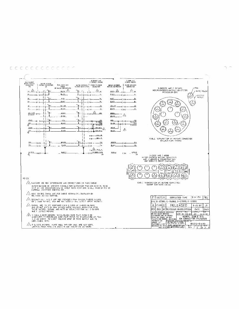
----·-----S-SE.:tti$
F Y'lltfiS E 1 9 to HOiCtl eucwt:u I tt:i iOn
P• I J< 22 cc:lll!:C!oo
.. & cr.if t! /n H -t----1- J-l.t--< A E----A--
) I I :t::_ __ ___flli =r· ! I < r. 8lA0' ---- I
.!!_ ) ) ! I ):::: YE:.I ow -----R-r-< f 1------_l.'.. > 1 1 +___ BlACK r-< • f----1:.
>- I I r eugw·r ·-}· : '-< H( & TIF.:at ldl I I + -.1..4- __ _ii _A_CK___ _ -1--) I ·" K >--i-f-:::r- ....Jlill!L I+F-<
t5111; )II) !-i-1= WHiff. II ( H r--)12>--l-f-!- PlACK J . . (
II II N( HAI! B
I I I I p ( !!ALL c I I , I 1
TS- j_ C>cACK _L ( s(---1.t
T .. H•ll A
1-530(1 M:J 1-66CC I'O TORS
Hotun EN':ODHi 1 HATING I CDNNF.CTcH
b'::. 6\ At
_ - -( 5
.l!U
(
L
r (
(
(
(
(
(
(
(
(
(
(
{
(
(
l (
(
{
t L t t L l)l 0 ll v lJ u u u
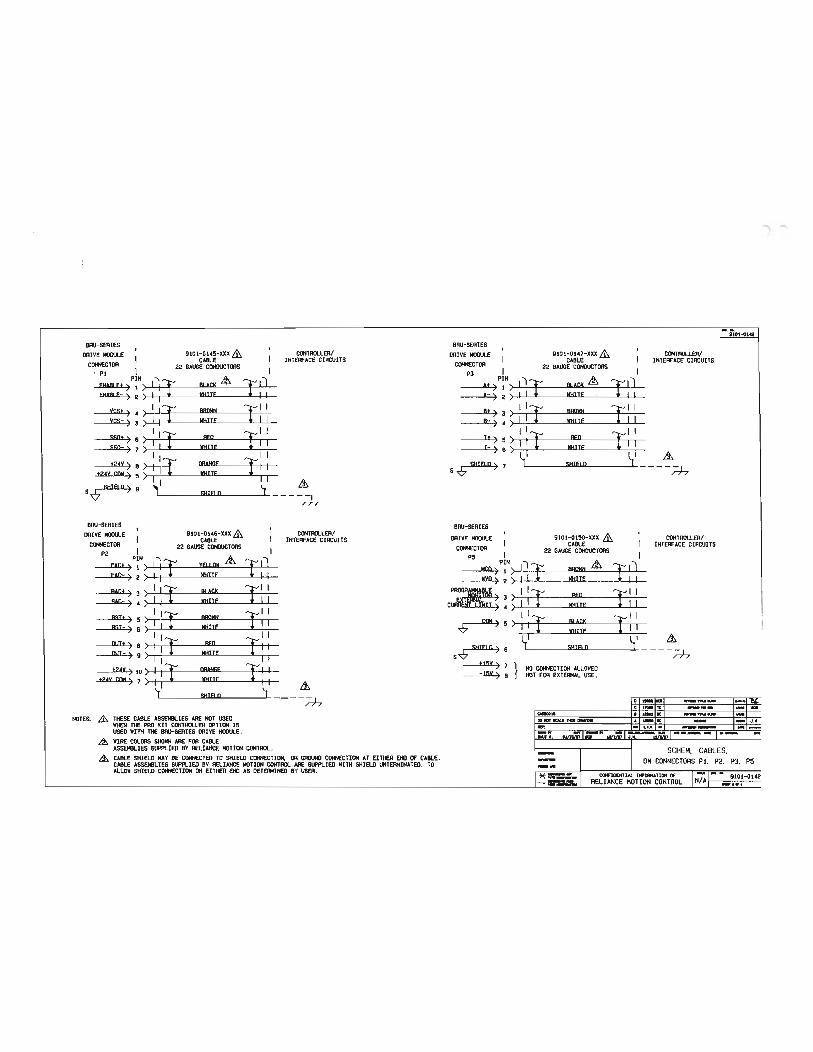
.......
..... 1101-o142
BAU-SERIES I I BRU-SERIES I I
DRIVE MOIJ\JLE & CONTROLLER/ DRIVE MOIJ\JLE _&. I CONTROLLER/ I CABLE I INTERFACE CIRCUITS I CABLE INTERFACE CIRCUITS COifiECTDR 22 GAUGE COIIlUCTDRS I CONNECTOR I 22 GAUGE CONDUCTORS I
• P1 I P3 PIN & FII&AI Ft P!N) :"': ::l:: BLACK & :1::: :] 1 ) :' :;:
e) --r- A-) 2
vest ) I : ::l:: Blllllltl :1::: I I ot ) 3 ) I I ::l:: BBOIIH :1::: I I yes-) ; ) IT IIHIT£ T1 I e-) I IT IIIIIT£ T1 I
I II ::::;;:I :;. I:: :;. & t2AY ) 8 ) : I ?: OOAHSF ! : : s SHIEl 0 ) 7 1 SHIEl 0 - - - - - I
t2AV CQM ) 5 > . I I jfHITf I . . ..& r77
SHIRO) ,1 '-. A, S
9 [ SHIB Q 4 - - - -
r77
BRU-SERIES 1 1 BRU-SERIES DRIVE MOil\JLE 9101-0U&-XXX & I CONTROLLER/ DRIVE MODULE 1 9101- 0150-XXX & 1 CONTROLLER/ I CABLE INTERFACE CIRCUITS I CABLE I INTERFACE CIRCUITS
COifiECTDR I 22 GAUGE CONDUCTORS I CONNECTOR 22 GAUGE COHOUCTDRS P2 PIN "' & J P5 PlN I :r y=:;; :: & r:J
BACt > > 1 : aucK 1 1 1 1 :t:: 1 1 BAC- ) ! ) I T IIHilE T I I ctMW'$1T ! ; I I T T I I
I 1:1::: :1:::1 I 1 I 1 1 :T :: T:: ..& 1:!14) 5 > .&. !
: ; : I r II:; =f : : S ..& SHIEl 0 ) 6 1 SHIEl 0 j ___ _ ;:..),
I tt5V ) 7 } NO CllltECTION ALLOWED 170; : : = T: : .&, -tsv) e HOT FOR EXTERNAL USE .
'J Q!IEIQ J o -ID _,.... -LX /"77 C t,_ ID __ ,__ ...._ a
I ._ IC ...._ NOTES: .£h Tt£SE CABLE ASSEIIILIES ARE HOT USED 110 ocrr -.r 1M111- • - 1C -- - J .M.
11HEH Tl£ PRO KIT CONTROLLER OPTION IS - oo o.u. " -- --USED IIITH Tl£ BOO-SERIES DRIVE MOOULE . 1:;': )"'- -MIRE COLORS SHOIIH ARE FOR CABLE ASSEIIILIES SIJ>PLIED BY REliANCE MOTION CONTROL . - SCHEM, CABLES,
.,&. CABLE SHIELD MAY BE CONNECTED TO SHIELD CONIIECTION, DR GRO\NJ CllltECTION AT EITHER 00 OF CABLE. - OM CONNECTORS PS, P2, P3. P5 CABLE ASSEMBLIES SIJ>PLIED BY RELIANCE MOTION CONTROL ARE SUPPLIED IIITH SHIELD UNTERMINATED. TO - • ALLOW SHIELD CONNECTION ON EITI£R 00 AS DETERMINED BY USER. ....
--iii:.=. RELIANCE MOTION CONTROL N/A -•••

(
L
r (
(
(
(
(
(
(
(
(
(
(
(
(
t t l
l l l l
" l_y
u ll lJ v u u u u (
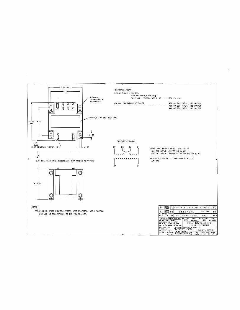
s. 50 MAX. 'I SPECIF ICATIONS,
OUTPUT POWER a S0/60Hz 110 VAC OUTPUT VOL TAGE SO'C MAX. TEMPERATURE RISE __ ___ SOO VA MIN.
NOMINAL OPERATING VOLTAGES __ ----- ______ --- 480 OR 240 INPUT, 120 OUTPUT 460 OR 230 INPUT, liS OUTPUT 440 OR 220 INPUT, 110 OUTPUT
CONNECTION INSTRUCTIONS 6. 2S 4.25 MAX.
& 8- 32 TERMINAL
l 8.0 MIN. CLEARANCE RECOMMENDED FOR ACCESS TO WIRING
,.....
0 f- .---- 0
l 10 0 = =
5.0
NOTES,
OR SPADE LUG CONNECTORS CNOT PROV IDED> FOR WIRING CONNECTIONS TO THE TRANSFORMER.
ARE REQUIRED
SCHEMATIC SYMBOL
rl X2 XI
INPUT CPR/MARY> CONNECTIONS: HI,H4 480 VAC INPUT o JUMPER H3 to H2 240 VAC INPUT , JUMPER HI to H3 AND H2 to H4
OUTPUT CSECONOARYJ CONNECTIONS: XI,X2 120 VAC
B lt98661SJIUPDATE TITLE BlOCK I12-20 - 91
A lt60021PSI RELEASED I 4-11-aa REV! ECO IBYI REVISION I DATE
UNLESS OTH!.WISE I'ECifi(O 00 NOT SCtLE DIH(NSIONS ARE IN INCHES UUK ill ('CU .01 HU. flllEI S l iiO lO<IIIOS tOUUMC( OJI, AMCl(S , Jt• fUCTIOHSo J 1/&14• OECIHILI• .II t .C ZO
.UH .OIC
, -.
BC BB
CHKR

(
r ' (
(
(
(
(
(
(
(
(
(
(
{
{
{
l l l G l G u u
L u v u u l
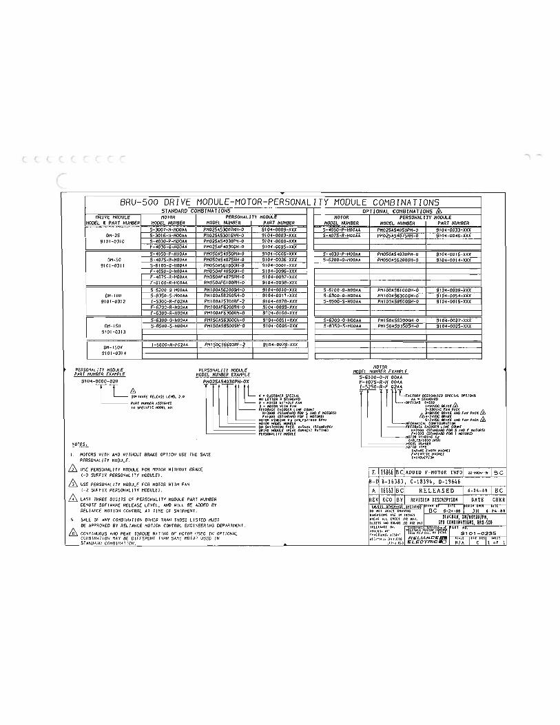
""' ......
T
BRU-500 DRIVE MODULE-MOTOR-PERSONALITY MODULE COMBINATIONS STANDARD COHBlNATlONS OPTl ONAL COMB l NA Tl ONS Ill
DRIVE MODULE MOTOR PERSONALITY MODULE MOTOR PERSONALITY MODULE HODEL £ PART NUMBER HODEL NUMBER HODEL NUHBER PART NUMBER HODEL NUMBER HODEL NUHBER PART NUMBER
5-3007-N-HOOAA PH02SAS3007NH-O 9104-0009-XXX S-4050-P-HOOAA PH025AS4050PH-O 9104-0033-XXX OH-25 5-3016-N-HOOAA PH025AS3016NH-O 9104-0003-XXX 5-4075-R-HOOAA PH025A54075RH-O 9104-0016-XXX
9101-0310 5-4030-P-HOOAA PH025AS4030PH-O 9104-0000-)()()( F-4030-0-HOOAA PH025AF40300H-O 9104-0095-JCXX 5-4050-P-HOOAA PH050AS4050PH-0 9104-0006-)()()( S-4030-P-HOOAA PH050AS4030PH-0 9104-0016-XJCX
DH-50 5-4075-R-HOOAA PH050AS4075RH-O 9104-0036-XXX 5-6200-0-HOOAA PH050A562000H-O 9104-0014-XJCX 9101-0311 5-6100-0-HOOAA PH050A561000H-O 9104-0001-)()()(
F-4050-0-HOOAA PH050AF40500H-O 9104-0096-XXX F-4075-R-HOOAA PHOSOAF4075RH-0 9104-0097-XXX F-6100-R-HOOAA PHOSOAF6100RH-O 9104-009B-XXX 5-6200-0-HOOAA PHIOOAS62000H-O 9104-0010-XXX 5-6100-0-HOOAA PHIOOA561000H-O 9104-0039-XXX
DH-100 5-B350-5-HOOAA PHIOOASB3505H-O 9104-0011 -XXX S-6300-0-HOOAA PHIOOA563000H-O 9104-0054-XXJC 9101-0312 I-5300-R-F02AA PHIOOAI5300RF-2 9104-0078-XXX S-B500-S-HOOAA PMIOOASBSOOSH-0 9104-0015-XXX
F-6200-R-HOOAA PH I OOAF620o.rm-O 9104-0099-XXX F-6300-R-HOOAA PHIOOAF6300RH-O 9104-0100-XXX 5-6300-0-HOOAA PHISOAS63000H-0 9104-0051-XXX 5-6200-0-HOOAA PHI50A562000H-O 9104-0027-JCXX
DH- 150 S-B500-S-HOOAA PHI50AS8500SH-O 9104-0005-XXX 5-BJ50-S-HOOAA PHI50ASB350SH-O 9104-0025-XXX 9101-0313
DH-150X I-6600-R-F02AA PHI50CI6600RF-2 9104-0079-XXX I I I I 9101-0314
PERSONALITY HOOULE PERSONALITY MODULE MOTOR HODEL NUHBER PART NUHBER EXAMPLE HODEL NUMBER EXAMPLE S- 6100-0-H OOAA
9104-0000-020 PH02SAS4030PH-OX F-4075-R-H OOAA
*'TUAAE AELEAS! LEVEL 2. 0
1-5250-R-F 02AA m '• m<- 9<M w'"' 110 LETTER • STANOAAO AA • STAIIOAIIO PART ASSIGNED 0 • HOTOR VIIHOUT FAN OPT I OH' BRAKE & TO SPECIFIC ttOOEL no. 2 • HOTOII UITH FAN
FEE09ACI( EHCOOER LINE COUNT 2•230VAC FAN PAC( & H•2000 ISTOOARO FOil 5 AHO F HOTOASI &3•90YOC 811AKE 00 FAN PACK f•IOOO ISTAHOAIIO FOR I HOIORSJ
AHO FAN PACK & RPHJ HfCHAHICAL CONFIGUAAIIOH 011 SUITCHING FA£0. A•StHr ISTAHOAAOJ FEE08ACK £HCOO£R LINE CIXIHI ORIVE ttOOU.E IPfAK CUAREHI RA IIHGI H• 2000 ISTAHDARO FOR 5 AHO F lfOIORSJ PfiiSOHAll TY ttOOU.E F•IOOO ISIAHOAiiO FOR I HOTORSI
NOTES, t!OOEl NlilfBEII ttOTOII TYPE
S•RARE EARTH HA GN€1 I. MOTORS WITH AND WITHOUT BRAKE OPTION USE THE SAHE F•FfRII!TE ttAGNfT
PERSONALITY HOOULE. I•INOIICTIOff
USE PERSONALITY MODULE FOR HOTOR WITHOUT BRAKE E 19866 BC ADDED F- HOTOR INFO C-0 SUFFIX PERSONALITY MODULE). USE PERSONALITY MODULE FOR MOTOR WITH FAN S- C- 18394, D-19646 C-2 SUFFIX PERSONALITY MODULE>. A RELEASED LAST THREE DIGITS Of PERSONALITY MODULE PART NUMS:R DENOTE SOFTWARE RELEASE LEVEL, AND WILL BE ADDEO BY RELIANCE MOTION CONTROL AT TIHE OF SHIPMENT.
5. SALE OF ANY COMBINATION OTHER THAN THOSE LISTED MUST BE APPROVED BY RELIANCE MOTION CONTROL DEPARTMENT ,
ffi CONTINUOUS AND PEAK TORQUE R.HING OF HOTOP. IJSEO IN OPTIONAL COHBINATION HAY BE DIFFEP.ENT THAN USED IN
T ANOARO COHO I NM I ON. ..... 1

(
(
(
(
(
(
(
t
t
t (
(
(.
(._
(._
L;
L v 0 lY Lv
L v u u
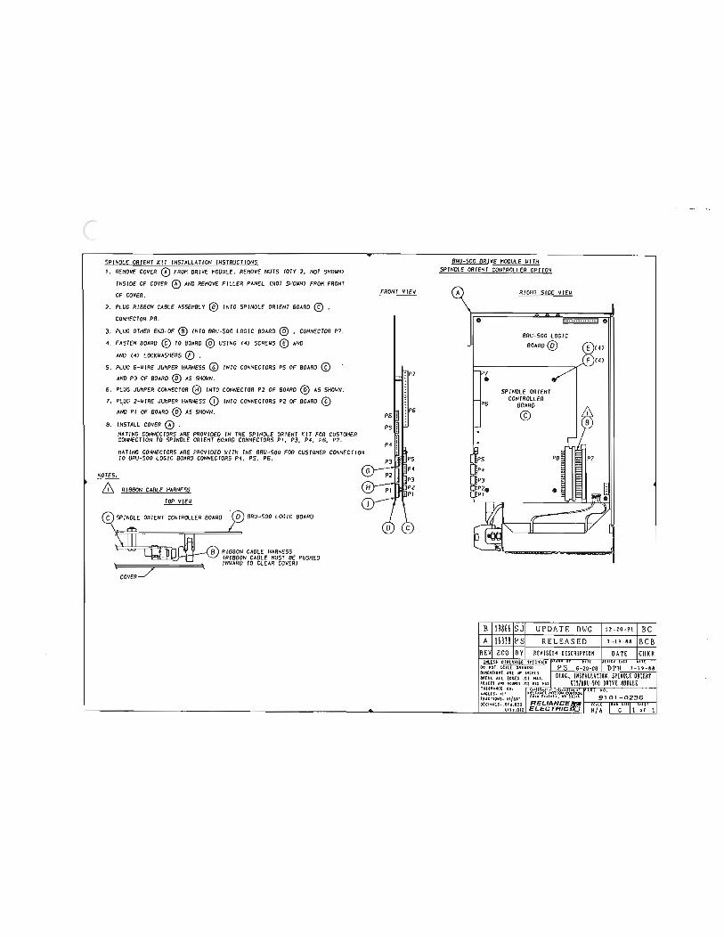
SPINDLE ORIENT KIT INSTALLATION INSTRUCTIONS ! . REHOVE FROH DRIVE NODULE. REMOVE NUTS COTY 2, NOT SHOUN>
INSIDE OF COVER AND REMOVE FILLER PANEL CNOT SHOWN> FROM FRONT OF COVER.
2. PLUG RIBBON CABLE ASSEMBLY INTO SPINDLE ORIENT BOARD(£) , CONNECTOR PB .
3. PLUG OTHER INTO BRU-SOO LOGIC BOARD(£}, CONNECTOR P7. 4. FASTEN BOARD (£) TO BOARD (£} USING C4> SCREWS AND
AND C4> LOCKWASHERS {f) . S. PLUG 6-WIRE JUMPER HARNESS INTO CONNECTORS PS OF BOARD (£)
AND P3 OF BOARD (£} AS SHOUN, 6. PLUG JUHPER CONNECTOR INTO CONNECTOR P2 OF BOARD (Q) AS SHOWN. 7. 2-UIRE JUHPER HARNESS <!) INTO CONNECTORS P2 OF BOARD (£}
AND Pl OF BOARD (£} AS SHOWN.
8. INSTALL COVER .
NOTES,
HATING CONNECTORS ARE PROVIDED IN THE SPINDLE ORIENT KIT FOR CUSTOMER CONNECTION TO SPINDLE ORIENT BOARD CONNECTORS Pl, P3, P4, P6, P7. HATING CONNECTORS ARE PROVIDED WITH THE BRU-SOO FOR CUSTOMER CONNECTION TO BRU-SOO LOGIC BOARD CONNECTORS P4, PS, P6.
RIOBON CABLE HARNESS TOP VIEW
0} BRU-SOO LOGIC BOARD
RIBBON CABLE HARNESS CRIBBON CABLE MUST BE PUSHED INWARD TO CLEAR COVERJ
FRONT VIEW
J' P6 P6 •!• •·
PS
P4 Uft : PS np· ]P3 ]P2 liP!
c
BRU-SOO DRIVE MODULE WITH SPINDLE ORIENT CONTROLLER OPTION
RIGHT SIDE VIEW
0 ( ................ 0
BRU-SOO LOGIC BOARD®
P7 • SPINDLE ORIENT
CONTROLLER P6 BOARD
J ©
•
B 19866 SJ UPDATE OWG 12-20-91 BC A 163J8 PS RELEASED 7-19-88 BCB
REV ECO BY R£VISION OESCRIPTIOH DATE CHKR OlHUWISE S'fCIFiiO •
00 "OT SCOL( OUWING OIH(NS IOHS U( IN INC H£!
,B!UK All EOG(I .01 HH.
:!':""s ..,.,, in cus • .,. •r. IAJ<Ct tmiON Q)llf1l L iFUCTIOMSo U/n• llu rutrh . ttl SUU. OteltUllo .lit .010 R ELIANC::E
.IIU .OIO ELEC::TRIC::lfQ
) l -.

I (
(
. ( ( (
L
(
(
(
(
(
(
(
(
(
(
(
(

(
("
(
I
I "
BRU-5ERlE5 DRIVE HODULE
RECE I VE tiOOf Pll n
»tfT HOOf XP'fiT LEVEl. P12 PI) n n
NOTES.
VELOCITY I'IOHJTM
( PS-8 ( -JSVOC !
PROCRAI'tiABt.E
PS-3 E ""'"'""
PJ-7 ( S>!IEtO i:rs
! I I I I POSIT l ON CONTROLLER P2-7
P2-6 P2•5 P2-4 P2-J P2·2 P2-l
LJ
"'' 24v
& , SHIELD COHN£CTIOH KAY Sf MOE AT ORIVE I'IOCI!Af oF CA9t.E. AS SH01ilrl. MAT cw>POSHE fll':l OF C48tE .
/
EX'TERNA{. CURRENT L( I'! JT
MOTOR
+24V
IS< +24V
15< •24V
15<
"":'- '1,

(
(
(
(
(
(
(
(
(
(
l .. l

F-SGries Notor Olmgns ions
HODEL
F40JO F4050 f4075 F6100 F6200 F6300
NOTES,
L1
2.
AS AJ AK p mm/in. & rnm/ in. in. mm/in. \0214.02 \45/5.7\ \ 10/4,)3 127/5.00 102/4,02 \4S/S. 71 110/4.33 127/5.00 10214.02 14515.71 II 0/4,33 127/5.00 131/S. 16 200/7.87 114.3/4.SO 17316. 81 131/S. 16 200/7.87 114.3/4.50 17316.81 131!5. 16 200/7.87 11 4.3/ 4 .50 173/6.81
EYE BOLlS INSIALLEO ON F -6100, 6200, 6300 MOTORS ONLY.
u EP mm/ln. mm/ in./1\ 19/.75 22 . 2/.875 19/ .7S 22.2!.875 19/.75 22.2/. 875 3511 . 38 J6.S!1.439 35/1.39 36. 5!1. 438 3S/I, 38 36.S/1.439
MOTORS ARE MANUFACTURED TO MILLIMETER DIMENSIONS SHOWN. I NCH DIMENSIONS SHOWN ARE APPROXIMATE CONVERSIONS FROM MILLIHfTERS. <EXCEPT I ON, DIMENSION EP IS MANUFACTURED IN INCHESJ
FOR FURTHER MOTOR DETAIL, ENGINEERING SPEC IF I CAT JON DRAIIINCS ARE AVAILA8LE UPON PEOUEST.
AM 88 mrl/ in. mm/ in.
50!1. 97 )/.12 SO/I. 97 3/.\2 50/\,97 3/.12 9013. I S 4/.16 90/3.15 4/,16 9013. IS 4/.16
CONNECTOR FOR OPTION lHIS
BF ,.m/ in. 10/,)9 10/. 39 10/.)9
13.S/.S3 13.51.53 1).5/.S3
XO s L wi th broke mm/in. rn..-lin. tnm/ in. mm/in. 40/\,57 6X61.24X .24 194/7.64 257!10.12 40/1.57 6X6/ . 24X. 24 272110.71 335113.19 40!1 . 57 6X6/ . 24X. 24 )50/13. 78 4\J/16. 26 60/2.36 IOX9/. 39X. 32 2SS!10.04 326/\2.83 6012.36 IOXB/.39X. 32 320112 .60 390!15.35 6012.36 IOX8/. 39X. 32 420/16.S3 490/19. 29
DIA HOLES - AJ OIA BOLT CIRCLE
0
F-4000 NOTORS, 116 x lm01 X IStnm/.59 INCH DEEP THREAD F - 6000 MOTORS , HB X 1.25mA x 20"""/. 79 INCH DEEP THREAD
A 11,.oo7s91 TM CHG 'D TEXT A I19866IBC RELEASED 11-25-91 JH
REVI ECO IBY IREVISION DESCRIPTION DATE CHKR UNLESS Olt!ERMISE SPECifiED
DO NOT SCALE ORAIII NG SJ 11 -25-91 JH Dl "GRAM, OUTLINE & MOUNTING
FILLETS At-() ROUNDS .02 R MAX F-SERIES MOTORS TOLERANCE ON, ANGLES t 1' FRACT IQNS,tl /64' 9101-0332 OECIHALS.Xxt .010 lfEiLIANCE-
.XXX•.OOS
""'\ -..

L
(
(
(
(
(
(
(J
l
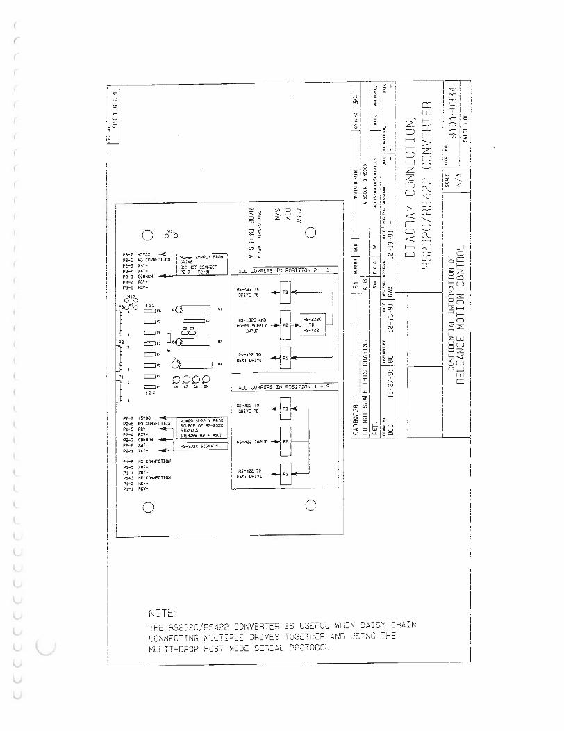
(
r
I (Tl j M: c •
, % c
I
I I
I I I I i
I I I I I . ! I : I I I I I
I
I I
I
I I I I
I
0 W:.l 0 0
?J- ? -.,;E-...,-; P::-0--:iiC-i< -SU-'F.,.-P<.-'1 -Fil::-0--.M I ?3- E hv COHN£:TrCN ! UAlVE.
I \no NO'i' cos."!Eti PJ-.C XMT+ I P2-7 ,.. P2· 3) PJ-3 Pl-2 ACV+ P3•! I<CV-
123 c=Jwa Clcl Ul
c=JW7 c::=::::::J "' C20 c=J••
c:=; .. I U3
c=J•• .. a c=J 113 I "'
c=J•• 0000 c:::J ., C6 Cl C8 "' 123
?2- 1 +5VOC ?2-6 NO CONNECTICS ?2- 5 ACV- I P2-4 RCV+
SOUIICE OF AS-232C SJG:<•Ls 1 IHEMOVE W9 + w 10) I ?2- 3 COM..aH I ?2- 2 XJ<T+
?2- 1 XI<T- -I
F, .. o NO CONN£CTION Pl-5 X"i• ?1-4 XMT+ Fl-3 NO CONNECTION P!- 2 RCY+ Pl- 1 ACV-
0
NOTE:
AS-232C s:G«•'-s 1
I I I
I
;; 0 m -z =
::::) > ......._ N {j'", z < c.n
-<
0 I
ALL Ju:-t?ERS FGS n!or; 2 + 3
AS-422 TC DRIVE P6
".5- 422 TO N£XT DRIVE
ALL JUMPERS !N 1 + 2
DRIVE P6 P3 i n3 1
I
AS-422 ! C NC:Xi Oio\IVE
0
I i !
w M: :: I !' I I :c I I ' 1;; I i I I --. I i ,. I I
I :! I : I I 0 •
I f :: ' 3 c: ... j :
< I f:, , ::; I
I I
I -I O:l 0 en
u c:l
01 I ,.....
('\J I
c:l u CD
I
1-;n I II I ,"'r')! , • O j i ! I ' .::: I i 1- '· ;:: 1 OJ I "' . I or. . .o I
I i ! I
:!. ...___ lg z I - -----1 : I i i ' l
H I . I l I . I
I
THE RS232C/RS422 CONVERTE; IS USEFUL WHEN DAISY-CHAIN CONNECTING MJLT iPLE DRIVES AND USI NG MULT I-DROP HOST MOQE SEHIAL PROTOCOL.

I (
(
( ( (
L·
(
(
(
(
(
(
(
(
(
l
l (
(
t t l t t (._,
ll l1 G v u u u u u ul
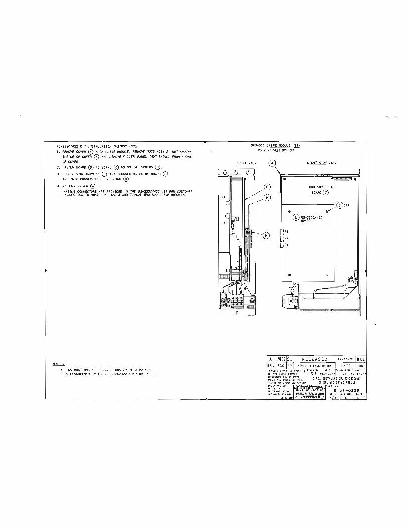
RS-232C/422 KIT INSTALLATION INSTRUCTIONS I. REMOVE COVER DRIVE MODULE. REMOVE NUTS CQTY 2, NOT SHOWN)
INSIDE OF COVER AND REMOVE FILLER PANEL CNOT SHOWN) FROM FRONT OF COVER.
2. FASTEN BOARD TO BOARD USING (4) SCREWS 3. PLUG 6-WIRE HARNESS (!) INTO CONNECTOR P6 OF BOARD
AND INTO CONNECTOR P3 OF BOARD 4. INSTALL COVER .
NOTES ,
HATING CONNECTORS ARE PROVIDED IN THE RS-232C/ 422 KIT FOR CUSTOMER CONNECTION TO HOST COMPUTER g ADDITIONAL BRU-SOO DRIVE MODULES.
I. INSTRUCTIONS FOR CONNECT IONS TO PI & P2 ARE SILKSCREENEO ON THE RS-232CI422 ADAPTOR CARD.
BRU-SOO DRIVE MODULE UITH RS-232C1422 OPTION
FRONT VIEW lA) RIGHT SlOE VIEW
BRU-SOO l OG IC BOARD©
$
P3 P2 PI
® RS-232CI 422 BOARD ·
RELEASED REVISION DESCRIPTI OII
UM\,.(SS _ OfHUWISE DO MOT SCALE DRAWIMG DIH!MSIDMS U( IM INCH(> UUK ALL (DC(l .02 HU. fiLLETS 1110 ROUPIOS .Ot UD Hll . TOL[UMCE OM. __ ..j ANC.l(S, tl" ULIAI<t t<rfiON CQI'!TJOL FU CTIOHS. tl /t!& • l4n Pulllt . x• UlU O(CIHILSo ,XU.OtO
.IIU ,OIO ELECTRICM:..J
'""'-

r (
(
(
(
(
(
(
(
(
(
(
(
(
(

l -··· -------, r- ·c· 1
I .... I 1114. 11 10.]1
-{1) (I) (I) It
I I
I I I I I
Becto·Craft' Ol I
I
I I
I r-- I I
I I
I r- I
I I .
IC I
I 15.1S
i[ W0.11
I
I I !· I
I f I
I !. I L-'-- I
[
I
I I ·--·-"'·"'- ·-.. I ..... -..... ..... _. __ ........ ., ... •IOIJ'U 'fiU " _ __ ,
I
r I I I ...
L ____ ___ jj NOlES: 1. MUS CONFORM TO SPEC. 7058-9978. 2. 'A' 4.00l102. 0)HINIHUH FOR & UN IT . ·a· 0 .50l13.0)HIN IMUM FOR BOTH SIDES OR ADJACENT UN ITS. ·c· 11 .00(280) CLEARANCE FOR CABLES.
t .ll IO'Sl.11
'lJ ..
.6
AIR EXHAUST 'lJ
6'\.
,_
11.! .. .. (4 44
'----
[W A
......
A I21170I TM RELEASED REVI ECO IBYIREVIS ION DESCRIPT ION \ltUSS OTHERII! SE SPEC!f IEP
00 NOT SCAL£ ORAIIING OIH£NSIONS ARE IN INCHES
ALL EDGES .02 HAX
DATE CHKR
ANO ROUNDS .02 R MAX TOLERANCE ON, ====...,.l==,..,--.-.....,,::;;;:;:_..:..::..: _____ -1
MOUNTING
.DXF ANGUS •1• FRACI IONS, 1 1/64. DECIHALS.xx• .010 REI.IANCE-
.xxx• .OOS EI.ECTR/C.O
"""-

(
L'
r (
(
(
(
(
(
(
(
(
(
(
(
(
(
(
(
{
(
l (
(
(
(
(
(.
l (.
(._;,
0 v u u ll u u u 0 {

NOTES, 1. MUS 2 .• A.
·a· ·c
l -··· -------, 1
tt4t'1':o,, IJI\·.'?1 A A 0 1--¥---
Bectro-Qaft• I lo-(6 ICI&il I
I I
0 I I
I I I I
I ,:,. I '· I I ..,..""' .. """ .. I ""'"'"' I
I I I I I
I ij
I
:MriiiiB I I
I a. ..... ,, .... "'""_,, _ _ a. .... , - .. u- ... t .. ,... ... , . .... """""'-ulu ... ....., . .. u.,.u \ .. _ .... ,. .... _ . .,_ I
I I I I I ··· I IJ L _______ _j
CONFORM TO SPEC. 7058-9978. FOR AIRFLOW,ABOVE AND BELOW UN IT.
O.SO<l3 .0lMINIMUM FOR AIRFLOW BOTH SI DES OR BETWEEN ADJACENT UNITS. 11 .00(280) CLEARANCE FOR CABLE S.
·c·
.. AIR
'1r EXHAUST
6
'1r
6'-..
i-
11. I·U4
SEE VI EW A
A I2 11 701TM RELEASED REV I ECO IBYIREVIS ION DESCR IPTION UNLESS SPEC!F )EO 00 NOT SCALE ORAUING DIMENSIONS ARE IN I NCHES
'""" ""
DATE CHKR
R HAX POWER SUPPLY , BRU-500 TOL£RANCE ONt Conf iMntioL o ANGLES :tl . H()l IOU CONIAOt. FRACT IONS, .t t / 64'" Eden Proi,. ••· I1N 5534<1 -. - - . - I DECI MALS. XX• . 010 RELIANCE- I sun IDIIC sm I SHHI
.XXX•.OOS ELECTRIC.Q . OXF
I -.

(
u
(
(
(
(
(
(
(
(
(
(
(
(
(
(
(
(
(
(
(
(
(
{
t ... (.
t t (._,
L G lY u (J.
u u lJ;
u L
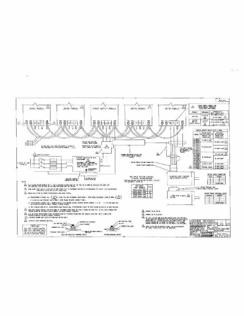
A
r
OR I VE MODULE & DRIVE MODULE & POWER SUPPLY MODULE
0C 80S f'OS, NfC, ANO CNO WIR£5 t1 £AW) I\ ARE PROVIOEO Wll._. OAIV( HOOUlE
) JSOI..U IOH OR AUTO TPANYORME"R. &
1 p .. ;.se "' LitE S0/60
(<W-1 JOHAL, NOT REOUIAEO WH(N OESIR£0 INI'IJT VOL TAG( as AVAILAOl[ OIA£CilV
NOTES,
& & &
FAOtt THE LIN£),
f'IACHIN£ COI'IHON GROl.Ml UtC BUS BAA
TO PAOl(tt IV£ UATH 1fRf11N.Al
CONTINUOUS HOTOR tuPR(NT MOONT£0 EI IHfR SIDE Of TJ*' PS.H IS 70 WS 0t tt;.)(J...utf P[A SIDE FOP 11-1£ PSK- 125, ANO 50 .t.HPS 0C rtA)IIHI.I1 Pf:A SJ()( ,.., PSI1· 50.
fUS£ 511£, CUSS A«S 90 .AttP tSOOO AICl A OISCOHNECUHC 0£VItf IS REQUIRED fOR SAfETY ... ,_, "AHH£NAHU . PStt-SO·Ul ClASS AKS •o AtiP t.SOOO AI()
NOl ES ON SIZING Of PO\o'EA TRANSFOQHERS AND I..WIJl \o' IAE S*
o) IRAWOAI€R J PtiASE tVA' (:lJ), ILINE- 10-LINE S{CONOAAY YOLIS !PER Pt<AS{ SECOIIOAin CORAEI<l RN5) •(:fj) 1000 1000
J lliHf·lO·liH€ PRIHAA'f VOlTS AHSl )( (PEA PHASE PPU4ARV Cl.AR{Nl A/151.
b) 1PANSF ORH£A l !:VA: tSUMr.AtiON OF EACH A.tiUAL AVEAlGE OUTPU1 POWERl (1.21 1. 2 fAC t OR ADOS 20:< AS IIOOC" EST I"Al£ Of OAIV£ HOOULE I 110101> LOSSES.
SU' !)RAVING 9101·01)2, 1R,U9=0Ptt£A LOAD P£CI.lATICtt, TO O£T£A11JHE EFFECT Of P£AK LOAOS ON S'YST£11 DC 90S YOLTACE.
& FOR WIRE CA\JGES 1<01£0, SIRIPP£0 ENOS Of STRAN0£0 WIRES HUSI BE FULLY IIN!f:O SO WIRE OIA. SlAYS LARC£ FOA PAOP!R tLAI'PING IN POW!A SIJPPlY HOOVLE OR ORIV! HOlME !!RHINAl-
& FCWl US CAlli£ 11010A PO\t£A WIR[, STRIPPED ENDS Of SUUIUO WIRES HOST B£ 0\'fR Af.fO FlJUY TINN£0 FOR PROP! A CLAI'PING IN OAIVE liOIM.! IERHINAL . & 1-S{RI(S 11010AS All£ \IS!O WllH IPIJ-500 010 .
DRIVE MODULE &
REL IANCE MOll ON CONTROL 3 PHASE TRANSFORMERS
VA( PAIIUAY, 1151230 'IA.C S£COHOART, 50/60 t4z
RELIANCE KVA PARI 0020-5091-001 3 0020-S091·002 6 0020-5091 -003 12 0020-5091 - 004 18_
& & &
1000\JE 10 24 L0 - 111 .
IOAOt( 10 11 . S LB· IN .
DRIVE MODULE £ I'ROOl!Cl
PSH-125
PSH-50 ,t.UO All
POII£R SIM'I'L Y HOOO.E AI<O OAIVE liOIM.( 1EJ>n1NALS ACCEPIABI.E WIRE RAI<Gf
IERIIINALS
QIOI-0411
10- .f
OR I¥£ HOOUL£5 1-4-12 AWGI2.5-4M1 &
16 A\IGJ I .Saft'&
MOTOR R,S,l , GNO
ffi
5- SERIES ANO F- SERIES AND W-SERI ES IIOTORS
110100 HOIOA POio{R HIN)H!Rt
ItA liNG CCIMCIOA AECOIKNQ(O COHlACT Sll£ POW(A \liRE lGA\Ai[/N!1 ) (CAUCEI""'' l
16 AWC/1 . 2M1
16A\IC/1.S.'&
12 A\IG/) , 01¥11
14
12 AVG/ 4U1 & 9
8 AWC/10b1
4 Awti/21.&.1 6 AWG/IS.a'
TEAHINAL BlOCl' 8 AWC/ I OM 6 A\IC/16M
HOIOR POWER CONNECTOR PlN SIGNAl A R B s c I 0 HO IOR CAS£
I I I I ttOfOA l(RHIN&L 90X I t POVEA l(RHINAl !i.TAIP I I I
1-5300 ANO 1- 66.00 ffi IIOIORS
HOIOA POWER TERHINAL STRIP tEAPtltul SICNAL
0 s v R w I E HOTOR CASE
In T(I:!HitU.l POSt tu.AO'IIARE OflAILSo
DO NOT OVERT IGHTEN USE NUl DRIVER ONLY
COt<N!CI IIIG
PO\t£ A SliP Pt. Y
1£PHINAL POST NUT
COON!tliNG LUGS £
M:. liNE fiLl ER AHD ttOIOA CABlE APE Of'TIONAL . 10 BE \ISEO FOR IHPROVINC TNE SYSIEH"S ELECIRO"ACNEIIC COI1PAIABILITY. WIRI NG BET\IE! N If!! POWER SUPPLY ANO FILTER St«lULO B£ AS StClfll AS POSSIIU , TNE CottMON CROON{) St<l\JLO BE AS CLOSE TO TNE HOOUL£ AS POSSIBLE .
WIRE SIZES AR£ R(COitH£NO.U IONS. 114' R£0UIA£ti£NTS CK- LOCAl IONS 1'\151 0£ OOS(RV'fO.
'lfS tO- IN U .O N•J A8SOl.U1E HAX IttUH 1 JGHIENIHC tOA(lJ(.
l(AHINAL POST
GftOlJNO IFf!M!NAl PQSI S
l -

(
L
I r (
(
(
(
(
(
(
(
(
(
(
(
(
(
(
(
(
(
(
l (
(
(
t (.
(
l t <..
G u u L v v {.;!
u u t
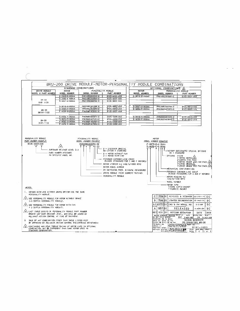
BRU-200 DRIVE MODULE-MOTOR-PERSONALITY MODULE COMBINATIONS STANDARD COMBINATIONS OPTIONAL COMBINATIONS ,
DRIVE MODULE MOTOR PERSONALITY MODULE MOTOR PERSONALITY MODULE HODEL & PART NUMBER MODEL NUMBER HODEL NUMBER PART NUMBER HODEL NUMBER MODEL NUMBER PART NUMBER
S-2003-K-HOOAA PNOIOBS2003KH-O 9105-0006-XXX S-3016- N-HOOAA PNOIOBS3016NH-O 9105-0001-XXX S-2005-K-HOOAA PNOIOBS200SKH-0 9105-0007- XXX
ON-I O S-3007-N-HOOAA PMOI OBS3007NH-0 910S-0000-XXX 9101-1131
S-3016-N-HOOAA PN020BS3016NH-O 910S-0002-XXX S-3007-N-HOOAA PM020B53007NH-0 910S-0013-XXX S-4030-P-HOOAA PN020BS4030PH-O 910S-0003-XXX S-40SO-P-HOOAA PM020B540SOPH-O 910S-OOOS-XXX F-4030-0-HOOAA PM020BF40300H-O 9105- 00S7-XXX
S-40SO-P-HOOAA PN030BS40SOPH-O 9105-0008-XXX S-3016-N-HOOAA PN030BS3016NH-O 910S-0015-XXX S-407S-R-HOOAA PN030BS407SRH-O 9IOS-0009-XXX S-4030-P-HOOAA PM030BS4030PH-O 9105-0012- XXX
DN- JO F-40SO-O-HOOAA PM030BF 40SOOH-0 91 OS-OOSB-XXX 9IOI-1133 F- 407S-R-HOOAA PN030BF407SRH-O 9IOS-OOS9-XXX
PERSONALITY NODULE PERSONALITY NODULE MOTOR PART NUMBER EXAMPLE HODEL NUMBER EXAMPLE HODEL NUMBER EXAMPLE
9105-0003-020 /\ PH020BS4030PH-OX F-1075-R-H OOAA t S-1030-P-H OOAA X = CUSTOMER SPECIAL t SOFTWARE RELEASE LEVEL 2.0 NO LETTER = STANDARD FACTOHY DESIGNATED SPECIAL OPTIONS
PART NUMBER ASSIGNED O = HOT OR Ill THOUT FAN AA = STANDARD TO SPECIFIC MODEL NO . 2 =MOTOR IIJTH FAN OPTI ONS O=STO f\. 4
I =90VOC BRAKE in FEEDBACK ENCODER LINE COUNT 2=230VAC FAN PACK
H=2000 CSTANDARD FOR S AND F MOTORS) 3=90VDC BRAKE AND FAN PACK & MOTOR WINDING KE CVOLTS/ 1000 RPM) 4:24VDC J\
'----- MOTOR HODEL NUMBER S-24VOC BRAKE AND FAN PACK ill ON SWITCHING FREO. B=IOkHz CSTANDARDJ MECHANICAL CONFIGURATION
FEEDBACK ENCODER LINE COUNT DRIVE NODULE CPEAK CURRENT RATING) H=2000 CSTANDARD FOR S AND F MOTORS) PERSONALITY MODULE MOTOR WINDING KE
CVOL TS/ I 000 RPM> '-------HODEL NUMBER
L-------MOTOR TYPE NOTES S=RARE EARTH MAGNET - --' F=FERR I TE MAGNET I . MOTORS IIITH AND IIITHOUT BRAKE OPTION USE THE SANE f\. PERSONALITY NODULE. C 19866 BC REVISED & REDRAIIN H-Nov - '>o BC in USE PERSONALITY MODULE FOR MOTOR 11/THOUT BRAKE
c-o SUFF IX PERSONALITY NODULEJ . B 19646 BC UPDATED DOCUIIENTATIOH 29 - HAY - 91 BC & USE PERSONALITY HODULE FOR MOTOR 11/TH FAN Al A00282BC CHC'D PH HODEL NO. 2-3 -89 BC
C-2 SUFFIX PERSONALITY NODULE) . A 16871 BC RELEASED 3-NOV - 88 BC & LAST THREE DIGITS OF PERSONALITY NODULE PART NUMBER REV ECO BY REVISION DESCRIPTION DATE CHKR
DENOTE SOFTWARE RELEASE LEVEL, AND WILL .BE ADDEO BY UOLESS OTHEowrs( s•!crr:!o P""' Ill rm• mr nr RELIANCE MOTION CONTROL AT TINE OF SHIPMENT. oo NOI sme ouwroc BC 3-NOV-88 JH 3-NOV-81
S SALE OF ANY COMBINATION OTHER THAN THOSE L1 STEO MUST DIACRAK, . BE APPROVED BY RELIANCE /10TION CONTROL ENGINEER ING DEPARTMENT. frum "'o m"'.•s .oz ••o Hu. STD COftB!NATIOHS, BRU-200
1\ .oM. NO. AND PEAK TORQUE RATING OF MOTOR USED IN OPTIONAL u .. "''" '· •• lllU I 9101 - 1053
COMBINATION MA Y BE DIFFERENo THAN SANE MOTOR U!':EO IN OEC;H>LS.'.xu.no RELIANCErr.1
'" I'" 11111 uu: ____ STANDARO COMBINATION.____ ______ .uu.oro £L£CTRICliCJ N/A I c 11 of 1
,-.

(
(
(
(
( (
(
(
(
(
(
(
(
(
(
(
(
(
(
l (
(
(
t t t t t l \.
<-> l, l!,
0 v \;;
u u l
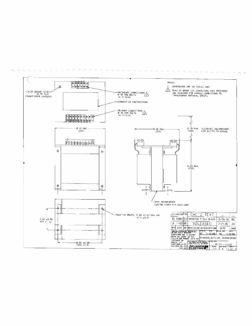
1/4-20 GROUND STUD (6. 35 OJ A)
(TRANSFORMER CHASSIS)
® ®
<f) <f)
14------- 8.00 ±0.06 I <203 ± 1. Sl
SECONDARY CONNE CT IONS/\ 8- 32 THO BOLTS (4.17 OJA)
CONNECT ION INSTRUCTIONS
PRIMARY CONNECTIONS 1\ 8-32 THO BOLTS (4. 17 DIAl
.... -NOTES, 1. DIMENSIONS ARE IN INCHES <mml
RING OR SPAOE LUG CONNECTORS (NOT PROVIDEOl ARE REQU IRED FOR WIRING CONNECT IONS TO TRANSFORMER TERMINAL STRIPS.
--r ECOMMEN0£0 a.d: MIN. WIRING (200) FOR r-------8.20 MAX .. (210)
9.20 MAX. (235)
3kVA TRANSFORMER ELF.CTRO-CRAF T P/N 0020-5097
MOUNTI NG HOLES, 0.28 t0. 02 DIA (4) (7.1 :t0.5)
B11Aoo7s91 TMI CHG, 0 TEXT B 11986615JI UPDATED TITLE BLOCK 112-20-911 BC A I17320IBC RELEASED
UN\ ESS OTHERWISE SPEW lfQ 00 NOT SCALE ORAI/lNG DIMENSIONS ARE IN INCHES
2- 23-89 I JH
MAX DIAGRAM, OUTLJ NE , TRANSFORMER TOLERANCE QN, ANGLES :tl • PEL IAHC.E ta-t CONIAOl FRACT IONS, tl / 64' •••• Pr o;r ; o, ""SSJ" I 9101 - 1056 O€CIHALS.XXt.OIO RELIANCE- SCILO liM:""' I -
.XXX•.005 ELEC:TRIC:•O
' .....

(
(
(
(
(
(
(
(
(
(
(
(
(
(
(
(
(
(
(
(
l (
(
(.
t l l L c 0 v (.j
G Gv
v t.,
u t
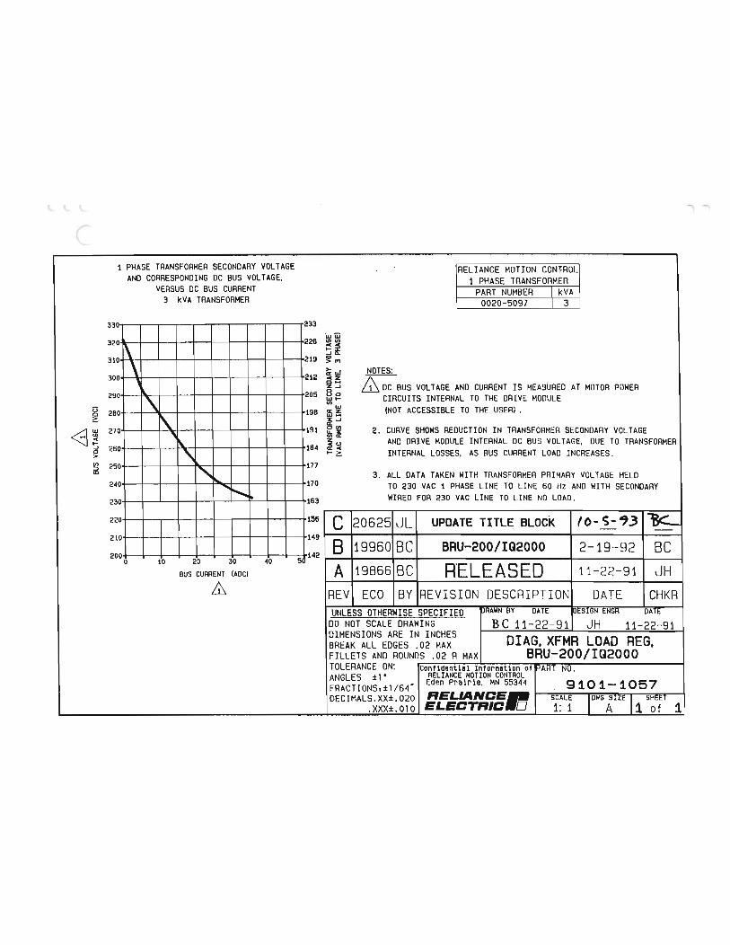
' -..
1 PHASE TRANSFORMER SECONDARY VOLTAGE RELIANCE MOTION CONTROL AND CORRESPONDING DC BUS VOLTAGE, 1 PHASE TRANSFORMER
VERSUS DC BUS CURRENT PART NUMBER I kVA 3 I<VA TRANSFORMER 0020-5097 I 3
330 233 i&J\ij
320 226 UJ en
r\ . 310 219 I') \ >- NOTES: 300 212 !l
BUS VOLTAGE AND CURRENT IS MEASURED AT MOTOR POWER 1\. 205 8 0 290 \ WI- CIRCUITS INTERNAL TO THE DRIVE MODULE en u 280 198 i (NOT ACCESSIBLE TO THE USER) . 0 i\. 270 ' 191 i 2 . CURVE SHOWS REDUCTION IN TRANSFORMER SECONDARY VOLTAGE \. z AND DRIVE MODULE INTERNAL DC BUS VOLTAGE, DUE TO TRANSFORMER
...J 260 " 184 INTERNAL LOSSES, AS BUS CURRENT LOAD INCREASES . 0 > en 177 ;::, 250 " CD 3 . ALL DATA TAKEN WITH TRANSFORMER PRIMARY VOLTAGE HELD
240 170 TO 230 VAC 1 PHASE LINE TO LINE 60 Hz AND WITH SECONDARY ......... i"- lot 163 HIRED FOR 230 VAC LINE TO LINE NO LOAD . 230
220 156 c 20625 JL . UPDATE TITLE BLOCK
210 149 8 19960 BC BRU-200/IQ2000 2-19-92 BC 200 20 30 40 5 142 0 10 R'ELEASED BUS CURRENT (ADC) A 19866 BC 11-22-91 JH & REV EGO BY REVISION DESCRIPTION DATE CHKR
UNLESS OTHERWISE SPECIFIED PRAWN BY DATE ENGR DATE DO NOT SCALE DRAWING BC 11-22-91 JH 11-22-91 DIMENSIONS ARE IN INCHES DIAG. XFMR LOAD REG. BREAK ALL EDGES .02 MAX FILLETS AND ROUNDS . 02 A MAX BRU-200/IQ2000 TOLERANCE ON: Confidential Information of PART NO . ANGLES ±1· RELIANCE MOTION CONTROL FRACTlONS,±1/64• Eden Prairie, MN 55344 9101-1057 DEC1MALS.XX±.020 SCALE l OWG SIZE 1 SHEET
.XXX±.010 ELECTFIIC 0 1: 1 A 1 of 1

r· (
(
( ( (
l;
( -(
(
(
(
(
(
(
(
l (
(
(
(
(
(
(
(
t l t (. ..._
(
... G \..;.
v v u (J
u u u u
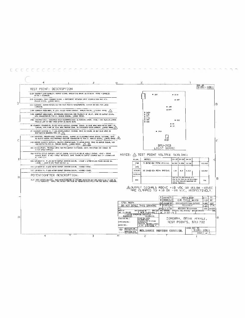
0
4 --- c 1
TEST POINT: DESCRIPTION CLD-l LOCf> El'lWLClt MP\JT S!Cifl.. INDICATI:-JC llllvt IS WIIJ.W. +5VDC • Etllff..ED,
0 V:!C • DISil!!lCO.
Cr:D (COtf»>DI: HPliT COI'I"AID SIG><H. • B£11-:([N lr-1'\JT SIC:.>¥•.5 VCS+ Rill VC5-. SIG.'"-• !_levOC RIWGE.
Cu"1 ICCtKf.<l: CCX1"KlN fOR T[5T PO!NrS .. 'TS. Cc:-T-o::N te VDCl fOR LOGIC CIRQJIIS.
lfllR ICIR>"l£NT r£(0 910<. I' LCGI: R l[C MOTOR CU'lRCNT. R'A..OG SIC'R., ! S.IMX: Rf«'"..C. & !WlC (ClJ<Il(I<T h'r..NilUOCl: OCTCR11li<S F\'oiD I'Ol.ffiJTY Of IR, IT . SIK AS OUTf'\/T S IC!<¥L
11CO ICOI<N:CTOR PS _0 1N ll. I'N'l.OG SICI-Il., !10VDC RR 'C.E. ------INST IJNSTRUCTIONl: IN:l!CJHES W£N MICROPROC£SSOK IS ReADING (f'ROH. +SVDC • NOT RlROING (f'ROH.
tn • sso
• CL(II • Cf':O • HVO • ltni • I1C'N
l9i0i - 1061 --
" !fER
e UDT
I • um e UDS
• osc 10 VDCI ....::N ErRCM IS OCINC RCRO. e COH t-
IR 1Cl1lRCI-fi C<l:i'A'-10 Rl: R LEG MOTOR COI1"ffl0. SIGNf\. IS SIN!: H'\VE >o-t:N MOTOR SlffT TURN!,.,. P.'"Pl.JlUOC Of 5!1J( PROPORTHN\. TO COI'rft\"OCO 1"-.."lTO'l !HWDC
f---------11 T): T LCG Sf-tiC kS SlGNf\. IR 9JT SIN( 1-R\/C IS
S>llrt[D z•a a:GRCcs rROrl IR. ---------------· =--------------------- ----------
•n • IR
e INST
II":O'JJT()Ill: OUTPUT SIG>¥1. , OUIPJT IS SCL£CIAilLC USING SCRIF\. l[R:'III<H.. . SR-:!: 115 OJlPJT PRX'ln'.-AilL[ MONilOR ICOI-M:CTOR P::. PIN 3l. FN\.OG S!Cin., +10VDC RRICC. & G1 c 1------ _-__ _
B
A
triO tMOTCR lli:LO:!H crJTPUTl: vourr..c PROPOkTJOr-a. TO MOTORK££,R- StK AS ourf'\/T S I CIR... tr:o ICO""-'CCTOil PS PIN 21. IN"I.OG S IGNf\., !10VDC ffi
05C IC"'-ILLATC<ll: TRII\""-.C 1-11'11: fOR PI-M Olllf\JT 5WJTCH!IlG. NOT(: M"'LilUOC ffiY Ofl'IGC AS ..,.-,rO'l Si'!:co C>A-JGCS.
15YS T[H STATUS OIJTf'\/Tlo OUTP\JT SICI$\. lr:rliCAlJNG !Jl!V( ...:IW..( STF.TUS. +SVDC • !Jl!VE 11CLU.C ReADY. 0 VDC • ffU.T OCTCCT£0. SI\'1C liMING AS OUTf'\/T S IINLS SSO u- ICCN-ICCTOR PI PINS S.?l.
Um Rl: R LEG ...:ITOR OUTPUI COiff"UO SICIA... +15VDC • tPPCR R L[G POIUl OCVICE ON. - ISVDC • R LCC 1'01-l(R LCIIICC ON.
1105 llP/OC«>> Sl: S LCC MOTOR OUIPVT SIC>A.. +ISVOC/- I SIIUC.
L"JT lli'/IY.'"--"1 Tl: T LCC MOTOR CUTf\JT COMM-"l-<0 SIC>¥\.. + ISVDC/- ISVDC.
POTCNT I 011ETER DESCRIPTION:
-
-----
R; N IVC5 FUlJUSll: THIS POT£Nllor--ET[R IS fACTO'lY AOJI."STCD WT N'Jl SC IT CR< 1!C r:;:Lo RDJUST£0. NOT£: lf<( orrS£1 CrY' F\.50 OC nOJUST£0 D!Gilf\.LY VIA Til: S£RIR.. TCRI11tfl.
R107
BRU-200 LOGIC BOf"-IRD --
NOTES: & TEST POINT VOLTAGE SCALING : SI<Nl- NOTES n-:-H) 01-20 01-30 <
If DR 5.0VOC•0.'1 f'EFI< RnTING e.see 0.250 0.166 VOCI'AOC
t-IRIPCA!<l 10.0\'DC•DM PEAK RATIIJG 1.0 0.5 0 . 333 VDC/RIY.:
t----HIPCA<l
HYO Of'NUUi "'Jl'f
HVO n., JS nt: un:: r.-c NlT..StPa..c VDC Vl."S H"-" 50\..J,.;t; tS£\.(C'I(D \IJR
!DIA.. lat1JNt.),
SIGNALS ABOVE +10 VDC OR BELOW - 10VDC ARE CLAMPED TO +10 OR - 10 VDC, RESPECT! VEL Y.
C 20Z4f BC AD!J£0 RJA7 S/_!;l __ DC B 19066 SJ CHG TITLE BLOCK l l/91 r--oc-
CAD: A0374 I AI fl<)[Jl!)! t----ill>CUMENTATION CHANGE B/89 r----
IIOC I-- DO SmLE IHIS DP.RWINs; __ lA li'3713
1·-f<Va SYI1 L:.C.O. GY I !AT( fn'I>OY1\.
.,. ..... IIY IIY .. ,. 1 .. :0 .... c ...... _ __ .... ,
1 ... c. ""'· ,..,.,.... ... rmcrrriTR<Ml. m·n:
llC 1-10-09 __acli..CZ2-B9 J H 2-22 -j:L - lN.£55 OlH:RWISC SKC!f![n -
-- £\.CCTRICA.. PJ)(WCA..l DIAGRAM, DRIVE MODULE,
pn>:ll- A<(. A«: JN JtrA:S TEST POINTS, BRlJ-200 10lCMU
rQCC1J?'6 rr.Cltn.S I ! ll't4 .! 7 ocN<Cr.c.ns orr sciii:. u-r.. Nil.
- ,- HtlH I"'I.,!f]OH)QI cm·rn-;o'- 9 101 - 1061 RI:J'R!;!DITS ... n I SIICCT I --- tt.Y.>lrtOlUON
'l 3 l.'). 2
I
B
A
'"'"'

(
(
(
(
(
(
(
(
(
(
(
(
(
t <..
L
u
l
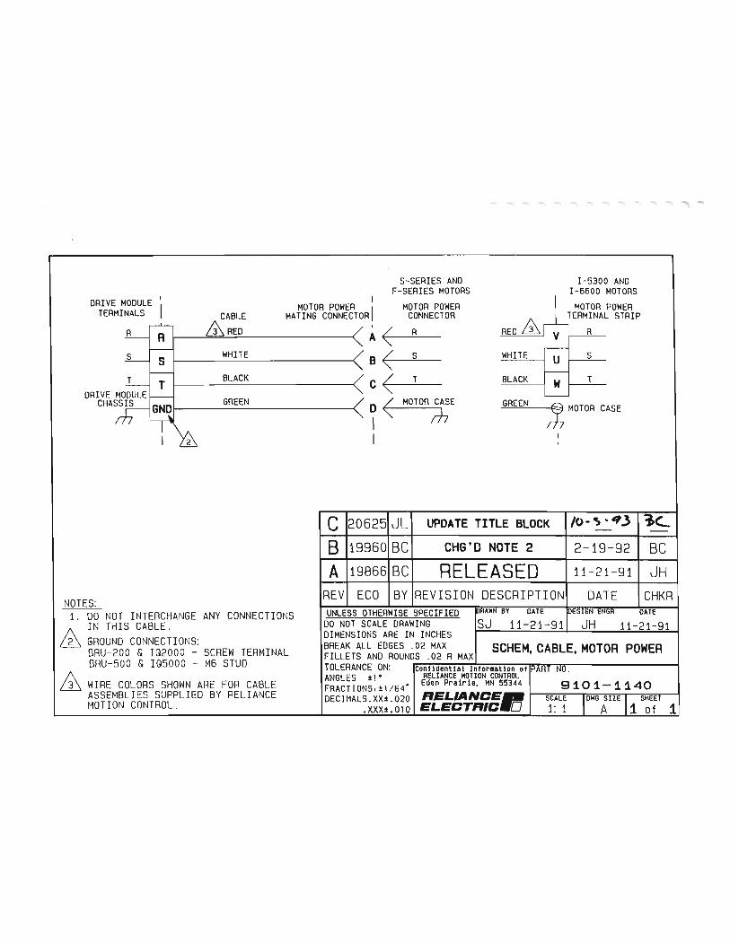
...... '"" ..... ...... """" """ -
S-SERIES AND I-5300 AND F-SERIES MOTORS I-6600 MOTORS
I MOTOR POWER I MOTOR POWER DRIVE MODULE i MOTOR POWER I TERMINALS CABLE MATING CONNECTOR CONNECTOR TERMINAL STRIP REO. & R &REO
WHITE
BLACK
GREEN
NOTES: 1. DO NOT INTERCHANGE ANY CONNECTIONS
IN THIS CABLE. GROUND CONNECTIONS: BRU- 200 & IQ2000 - SCREW TERMINAL BRU-500 & IQ5000 - M6 STUD WIRE COLORS SHOWN ARE FOR CABLE ASSEMBLIES SUPPLIED BY RELIANCE MOTION CONTROL.
A( R R
a( s WHITE s
c( T BLACK T
O < MOTOR CASE GREEN ;}; MOTOR CASE I rh I I
I
C 12 0 6 2 51 J l I UPDATE TITLE BLOCK 1o- -; .. • 3 I B I19960IBCI CHG'D NOTE 2 2-19-92 BC A I19866IBC RELEASED 11 -2 1-911 JH
REVI ECO IBYIREVISION DESCRIPTION DATE CHKR UNLESS OTHERWISE SPECIFIED BY DATE ESIGN ENGR - DATE-
DO NOT SCALE DRAWING SJ 11-21-91 JH 11- 21-91 DIMENSIONS ARE IN INCHES BREAK ALL EDGES . 02 MAX SCHEM CABLE MOTOR POWER FILLETS AND ROUNDS .02 R MAX ' ' TOLERANCE ON: confidential Infor11at1on of A 0 . ANGLES :t 1 • RELIANCE MOTION CONTROL FRACTIONS' :tl / 64' Eden Prairie, MN 55344 . 91 Q 1-1140 DECIMALS. XX:t. 020 IIEL.IANCE.. SCALE
.XXX±.OlO ELECTIIIC.O 1: 1 1

(
L
(
(
(
(
( (
(
(
(
(
(
(
(
(
(
(
(
(
(
(
(
(
(
(
(
(
(.
(._
(.
(._
l L 0 u u G u u u u
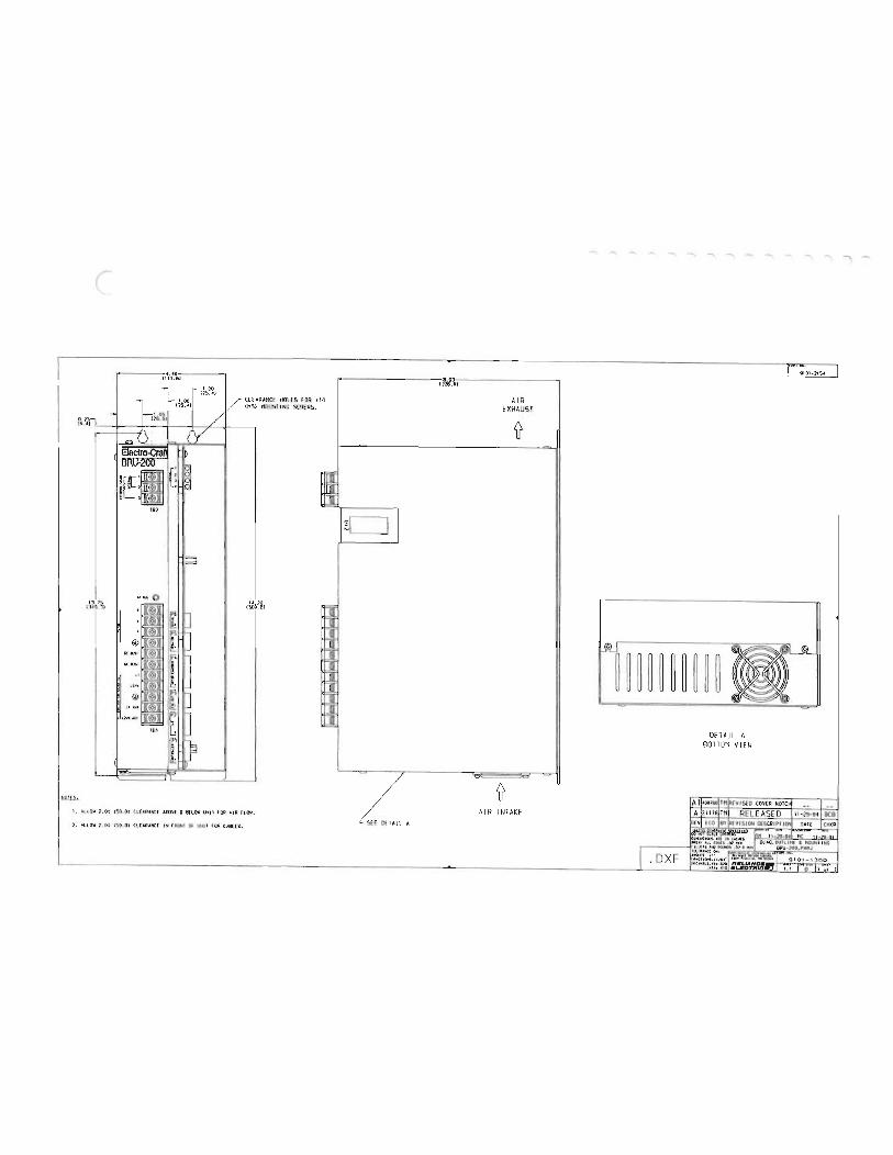
r
182
liQ!.f.h
CLEA lMSl
RANCE HOLES FOR • MOUNT INC SCREWS.
1. ALL0\1 1.00 (50.8) CLEARANCE .lOO¥( l BELOW liH 1 FOR A.IR fLOW.
2 . ALLOW 2 . 00 t50 . 8) CL£AP:,t.MC£ IN fROtH OF UtHl FOA U8L£S.
10
=
I
F
!:
/
SEE OfiAJL A
t!i69.1at
AIR EXHAUST
{(
.
...... -. - -.
.OXF
DETAIL A BOTTOM VIEW
._ ....... --

(
L
(
(
(
(
(
(
(
(
(
(
(
(
(
(
(
(
(
l l (
t l l l (_
l G 0 u l_y
u
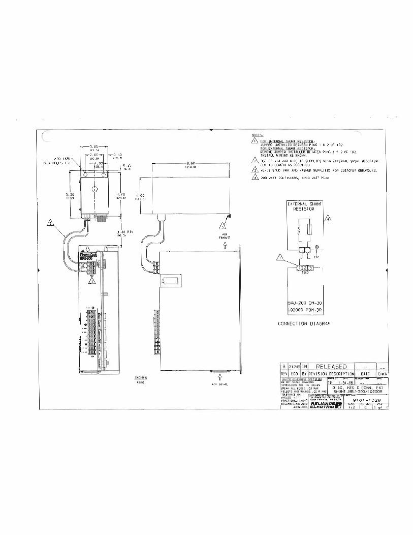
, 10 ( MTG HOLE S (3)
.25
,_
!218, 4) ,. 8.60
I 4.00
'"L'--r-r--------::i
lllli!E..S (mml
AIR EXHAUST
'if
'if AI R INlAKf
- -FOQ INTERNAL SHUNT QESISTOQ, JUMPER INSTALLED BETWEEN PINS 1 g 2 OF TB2. FOR EXTERNAL SHUNT RESISTQQ,
.......
REMOVE JUMPER INSTALLED BETWEEN PINS 1 g 2 OF TB2.
..... ..... """"
INSTALL WIRING AS SHOWN. . 36" OF •14 AWG WIRE IS SUPPLIED WITH EXTERNAL SHUNT RESISTOR. CUT TO LE NGTH AS REQUIRED. •6-32 STUD (NUT AND WASHER SUPPLIEOJ FOR CUSTOMER GROUNDING.
200 WATT CONTINUOUS, 6000 WATT PEAK .
EXTERNAL SHUNT RESISTOR
BRU- 200 OM-30 102000 POM-30
CONNECTION DIAGRAM
A I212491TM RELEASED REV! ECO IBY IREVISION DESCR IPTION lml...£55 OTHERWISE '5PH:: IF IFn
DATE CHKR DO tiOlSU!TORAIIING TM 1- 31-95 -- --DIMENSIONS ARE IN INCHES BREAK ALL EDGES .02 MAX 0 I AG , MTG & CONN, EXT F ILLElS AND ROUNDS .02 R MAX SHUNT, BRU-200/ I 02000 TOLERANCE ON , ANGLES .,. Pl'LIANC( t'WlTIC»-1 FR.ACT IONS,tl/64 ... Eden Proiri•. HN SS:SH -,...., , , -'-'-' DECIMALS. XX• .010 RELIANCE-I <txt! "'"'·""'I GaLl
.XXX• .005 ELECTRIC . O
1-

(
(
(
(
(
(
(
(
(
(
(
(
(
(
(
(
(
(
(
(
(
t (
(
(
4...
t t 4...
4...
L l Lt
L u u
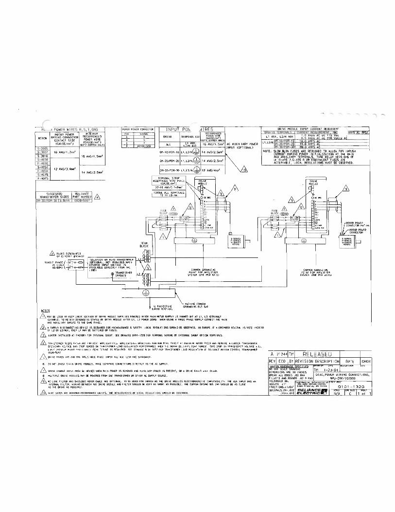
...... - """ -.. 1 ...... -- - INPUT PO\-. rJIRES DRIVE MODULE INPUT CURRENT REOUIREH' .<POWER WIRES R,S,T,GND HOIOA POIIER CONNECtOR MINIMUM PIN SJCNAI.. RECOHI1ENDED BR\ I IERI1 NA.S URRENT REO\IREI1EN NA AMPS A RMS:
MOTOR POWER ri: m ... r. HATING CONNECTOR RECOMMENDED A A DRIVE TERN I NAUSJ POIIER WIRE L1 AUX, L2/N AUX MOTOR POWER WIRE s ICAUGEI""' l
CONTACT SIZE !GAUGE/11m' l 9 cso• C COPPEP ONl 'f)
L I, 10 AMPS AC
!CAUCE/111• ' l c l I 16 AIIG/1 . Smro' AC AUXILIARY POIIER 19.0 AMPS AC <&o•c COPPeR ONL'fl ALL 0 IOOTOR CAS{ INPUT <OPT I ON ALl - /!' 11- AMPS A S -2005
5 - 3007 16 AWG/1 . 2mm' DM-10/PDH-10 1 4 AIIG/2. Smm' NOTE, SL0\1 BL0\1 FUSES ARE REQUIRED TO ALLOW FOR INRUSH CURRENT DURING POWER INITIAL I ZAT ION AT THE MAIN
S-3016 16 AIIG/1. Smm' L1,L2/ N,@
AND AUXILIARY TERMINALS. TIME DELAY VERSIONS Of S- 4030 DII-20/PDM- 20 14 AWG/2. Smm' UL CLASS J,CLASS R OR EQUIVALENT FUSES ARE F- 4030 ACCEPTABLE, LOCAL REGULATIONS MUST BE OBSERVED. S-40SO 12 AIIG/3. Omm' ' F-4050 14 AIIG/2. Smm'
OH-30/POM- J0 12 AIIG/4"""' 10 i S-4075
F-4075 TERMINAL STRIP - ACCEPTABLE WIRE RANGE 1\ DRIVE DRIVE -· v 21-10 AIIG/0.5-6"'' 9 ..... SUGGESTED II RELIANCE Rl & &/ ... TRANSFORMER SIZES PART NUMBER 4 TO II LB-IN. '"' 0 0C II.'> ODCIUS 011-30/ PDM-_30 I). OkVA 0020-S097
. & - , & 1 fUSE !' fUSE + <EmD '(_ BLOCK <llll!D ot• '(_
l1 - DC-
,.-' ::j:C'K " I (!,'"
. fllUA 1.1tH
:I r---' @ :.!::OR POWER ll .&U) " "" CONNEClOR HAT lNG &I l>fNM l:lOI IIU)t
'-- ,- 1 M. MOTOR POWER CONNECTOR 1 r-
I @ I I l I @ I ..... ,.. r F-Sf:RI[ S TERM = ""';"'" -=- W- SEAIES
aOCK
ffi FUSED DISCONNECT .m OR CIRCUIT IIPEAKER ISOLA! JON OR AUTO IPANSFORHER
SI NGLE PH•SE{TJ ., <OPTIONAL, NO! REOUIRED WHEN \7 r<>' DESIRED INPUT VOL lACE IS
DIRECTLY fROM l HE L INEl COHHON GROUNDING COHHON GROUNDING 1> TRANSFORMER 71f POINT fOR AHPLlf IER POl Nl fOR AHPL IF lER
SYSTEH <ONE P{P AX lSl SVSIEH <ONE P{R AXJSl
I
HACH I NE COHHON ! TO PROTECTIVE GROUNDING BUS BAR tllill5 EARlH lERHINAL
ffi tiAY 8£ USED 10 <EEP LOGIC SECIJON OF DRIVE HOOUI.E SUPPLIES POWERED AflER tt•JN HOTOR SUPPLY IS Tl.!lhED Off AT Ll. L2 TERMINALS !OAtf>LEo TO REIAIN OJAGHOSIJC STAIUS Of DRIVE HOOULE AftER Ll. L2 POWER OOIONl . IIHEN USING A PHAS{ SUPPLY CONhECI lo<E HAIN AND AUXILIARY INPUTS 10 To<£ SAI1E PHASE. ffi A SUPPLY DISCONNECT ING DEVICE IS REQUIRED f OR HAINIAINANCE t SAfEn . LOCAL REGULATIONS SHOULD BE OBSERVED. IN EUROPE. IF A GROUNDED IS USED lNSlEAO OF L2 OR L2/AUX, ONLY L1 HAY BE SWITCHED OR fUSED. & Jlt1P£R INSTALLED AI FACIORY FOR INlERNAL SlfJHI . S{E DRAWING 9101 - 1328 fOR IERtiiNAI WIRING Of EXTERNAL SIWT OPIJON TERMINAlS.
& IRANSFOR11ER SIZES SHOWN ARE FOR MSl APPLICAIIONSo APPLICATIONS REOUJRING PEA< TOROUf AI H•XIMUH t1010R SPHO HAY REQUIRE A LARGER IAAN5f0Rt1ER. SECONDARY VOL lACE tt•Y DROP IBAS£0 ON 1PANSFORI1ER LOAD AE GUL"TION PEAFORHANCE> WHEN THE HOTOR DELIVERS PEAt THIS DROP IN IRAHSFORHER VOLT•GE WILL LIHil tt•XIIUI HOTOR SPHD WHILE PEA< IORO!AO IS PEOUIREO. SEE ORAWINC 9101-IOS7 FOR IP,IISFORHfP LDAO PECULATION Of RELIANCE HOllON CONlROL TRANSFORHER 0020-5097. A 21244 TM RELEASED ffi DRIVE PAlEO 100-240 v•c RHS,SINCLE PHASE INPUT VOlTAGE <ZJO VAC S"'NOARDl.
REV ECO BY REVISION DESCR IPTION DATE CHKR 6. DO NOI DAISY CHAIN DRIVE HOOUI.ES. HAtE SEPARATE CONNECIJONS OJR!'CILY 10 IHE AC SUPPLY .
ffi DAlY£ ENABlE INPUT 11\JSI BE OPENED IIHEN HAIN POWER IS REHOYEO AND AUXILIARY POIIER IS PRES{NT, OR A DRIVE FAULT WILL OCCUR . U!!.m SeEtiE lEg ""'"" •. UAI. "' 00 NOT SCAL DRAWING TH 1-23-94 OIHENSJONS ARE IN INCHES
9. HLUIPLE DRIVE HOOULES HAY 9£ POIIEREO FROH ONE IRANSFORI<ER OR OIHER AC SUPPLY SOURCE. BRE ALL EDGES • 02 11AX DIAG.POWER WIRING CONNECTIONS,
& AC LINE FILlER AND SHIELDED IOOIOA CABLE ARE OPTIONAL. 10 Of USED fOR INPROVINC lHE DR IVE HOOUI.£5 ELECTROHAGNEI1t COtf>AlABILIIY. THE AUX INPUT HAS AN FILLETS AND ROOOOS . 02 R MAX BRU- 200/ 102000 lOLEPANCE ON . 1ntouot1on or
IHIERNAL fiLlER . "IRING 81'11/EEN THE DRIVE HOOULf AND fiLTER SHOULD BE <EPl AS SHORT AS POSSIBLE. THE CO!<OION CROVND 9US DAR SHDULO BE AS CL OSE ANGLES 1. AEli.UC.f (OHlPOl TO HE OR I VE AS POSSIBLE. FPACT IONS,t116 ... Eden Proir te, HN ss-,H 9101-1329 "IRE SIZES APE HlNIHIJH R£C01111ENDED VALlA'S. THE REOUIRE01ENIS Of LOCAL SO<OO..D DE OSSfRVEO.
DEC IHALS.XXt . 020 1 '"l .. ,XXXt.OIO ELECTRIC N/A ___ C_ l <>L 1

(
r (
( (
(
(
(
(
(
(
(
(
(
(
(
(
(
(
(
(
t ( (
(
(
(
(
(
(.
l (.,
u u u ' !.
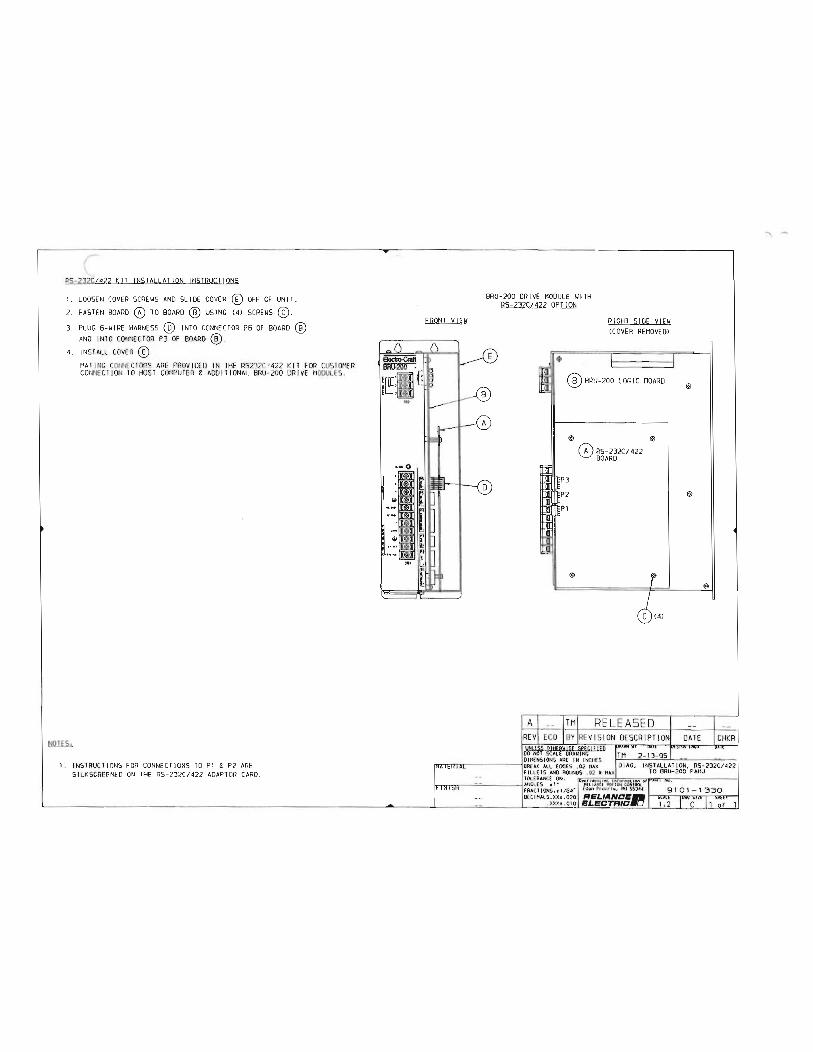
RS-232C/422 KIT INSTALLATION INSTRUCTIONS
I. LOOSEN COVER AND SLIDE COVER([) OFF OF UNIT. 2. FASTEN BOARD TO BOARD USING (4) 3. PLUG HARNESS (Q) INTO CONNECTOR P6 OF BOARD
AND INTO CONNECTOR P3 OF BOARD 4. INSTALL COVER ®
llil..!..E..S..
MATING CONNECTORS ARE PROV IDED IN THE RS232C.'422 KIT FOR CUSTOMER CONNECTION TO HOST COMPUTER & ADDITIONAL BRU-200 DRIVE MODULES.
I. INSTRUCTIONS FOR CONNECTIONS TO PI & P2 ARE SILKSCREENED ON THE RS-232C/422 ADAPTOR CARD.
FRONT VIEII
.....
BRU-200 DRI VE MODULE WI TH RS-232C/422 OPTION
A
$
RIGHT SIDE V!HI CCOVER REMOVED>
® BRU-200 LOGIC BOARD
@ @
P3 P2 PI
@
TM
0 RS-232C/422 BOARD
RE LEASED
VtHSS Olt!Epl!!SE SPEC!f!Ep 00 NOT SCAL£ ORAI!ING DIMENSIONS ARE IN !NCtiES
IHAIERIAI lsREAK ALL EDGES . 02 HAX
(§)
FILLE TS AND . 02 R MAX lOLERANCE ON • "c"'on"r"'o•;,...,,.,,.,, • .,..,.,.,.J..,,.,.,.,.••"'"<""ooo,--o'"'r ! =- !.INGLES sl• A£lUHC£HOIJ0NtON1AQ..
•r Nr -.H Prolrlo, tiN 55344 __ _ DEC!HALS.XX• .020 RELIANCE- I scxtt !owt Silt 1 s'*"
. XXXt.OIO l!LEDTRID•O
.... 1 .......

(
L
(
(
(
(
( (.
(
(
(
(
(
(
(
(
(
(
(
(
(
(
(
(
(
(
l {
l l l L t1 0 ll lJ ll u u u u
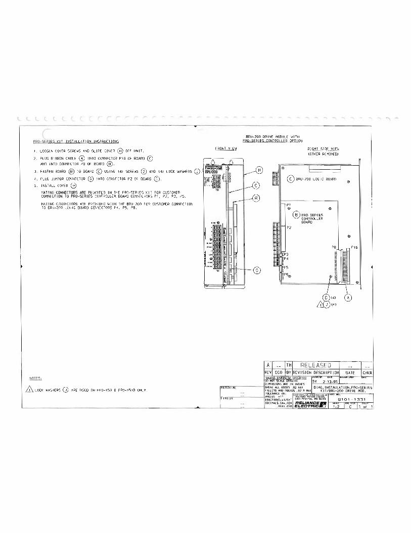
PRO-SERIES KIT INST ALLATION INSTRUCTIONS
I. LOOSEN COVER SCREWS AND SL IDE COVER UNIT. FRONT VIEW
2. PLUG RIBBON CABLE INTO CONNECTOR Pl6 OF BOARD AND INTO CONNE CTOR PB OF BOARD
EJ8CUOOCiiiri 3 . FASTEN BOARD TO BOARD USI NG (4) SCREWS (§) AND (4) LOCK WASHERS {1). , 4. PLUG JUMPER CONNECTOR @) INTO CONNECTOR P2 OF BOARD If([ I {: 5. INSTALL COVER @ !C.:>
NOTE.fu,
HATING CONNECTORS ARE PROVIDED IN THE PRO-SERIES KI T FOR CUSTOMER CONNECT ION TO PRO-SERIES CONTROLLER BOARD CONNECTORS PI, P2, P3, PS.
HATING CONNECTORS ARE PROVIDED WITH THE BRU-200 FOR CUSTOMER CONNE CTION TO BRU-200 LOG IC BOARD CONNECTORS P4, PS, P6.
.. ,
-BRU- 200 DR IVE MODULE WITH
PRO-SERIES CONTROLLER OPT ION
@
RIGHT SIDE VIEW (COVER REMOVEDJ
® BRU-200 LOGIC BOARD
PI @ @
P2
® PRO-SERIES CONTROLLER BOARD
@
(§)
PB I _ P16
A ™ RELEASED liNLESS JlTHfpl!fSE SPfC!E !Eo 00 NOT SCALE ORA \I I NG
@
WASHERS(!) ARE USED ON PRO-XSO & PRO- XSOB ONLY. '
DIMENSIONS ARE IN INCH£5 "'""'Ani"I:I'TIDrTI">"Arl ------4BREAK ALL EOGES .02 DIAG, INSTALLATION, PRO-SERIE S
FILLETS AND ROUNDS • 02 R KIT / BRU-200 OR I VE MOD . TQERANCE ONl tont ld•nllol IMOt"".ot lon ol I -- !.aNGLES :tl • A£\.IAHC£1"01t0N CDHTRQ..
t= IN ICJ4 FRACl iONS. J.l /64- £0$t'l Pro lt le, HN SSJ<t<t DECIHALS.XXt.020 RELIANCE-
.XXXt.OIO ELECTRIC•O
1 -.

Appendix A -Getting Started With the Tandy 102 Terminal
60
APPENDIX A- Getting Started With the Tandy 102 Terminal
The following procedure outlines the steps required to establish BRU-Series drive communications using the Tandy 102. Refer to the Tandy 102 owners manual for switch locations and initial power up instructions.
1.)
2 .)
3.)
4.)
5.)
6.)
7.)
After powering up the Tandy 102, press function key Fa to bring the main menu to the screen.
Move the program selector using the arrow keys or the space bar to the "TELCOM" program and press [ENTER). The telecommunications program will be executed which allows the Tandy 102 to communicate to the BRU-Series drive.
The top line of the screen is the status code which indicates the TELCOM communication parameters (for example, "M711D,10 pps"). This code must be changed before the Tandy 102 will talk to the BRU-Series drive. To change the code, press function key F3. The "STAr prompt will be displayed beside "TELCOM."
Type "88N1E" and press [ENTER). The communications parameters are now set to the required values. For an explanation of this code refer to the Tandy 102 owners manual.
Select terminal mode by pressing function key F4.
Terminal mode functions are displayed on the bottom line of the screen. The word "FULL" (full duplex) should be displayed above [4). It "HALF" (half duplex is displayed, press function key F4 to change to "FULL".
Connect the RS-232 interface cable (9097-1040-010) between the Tandy 102 and the BRU-Series drive. Press <ESC> and the Tandy is ready to communicate with the BRU-Series drive.
BRU-200/BRU-500 Brushless Drives Instruction Manual
(
(
(
(
(
(
(
(
(
(
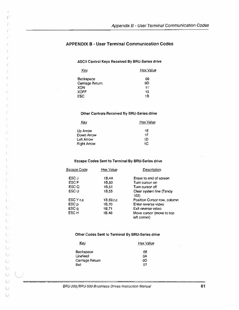
(
(
(
Appendix B - User Terminal Communication Codes
APPENDIX B - User Terminal Communication Codes
ASCII Control Keys Received By BRU-Series drive
Backspace Carriage Return XON XOFF ESC
Hex Value
08 00 11 13 18
Other Controls Received By BRU-Series drive
UpArrow Down Arrow Left Arrow Right Arrow
Hex Value
1E 1F 10 1C
Escape Codes Sent to Terminal By BRU-Series drive
Escape Code Hex Value Description
ESCJ 1B,4A Erase to end of screen ESCP 18,50 Tum cursor on ESCQ 18,51 Tum cursor off ESCU 18,55 Clear system line (Tandy
102) ESCYr,c 1B,59,r,c Position Cursor row, column ESCp 1B,70 Enter reverse video ESCq 1B,71 Exit reverse video ESCH 18,48 Move cursor (move to top
left corner)
Other Codes Sent to Terminal By BRU-Series drive
Backspace Unefeed Carriage Return Bell
Hex Value
08 OA OD 07
BRU-200/BRU-500 Brushless Drives Instruction Manual 61

Appendix C- Getting Started With an IBC PC Terminal
62
APPENDIX C Getting Started With an IBC PC Terminal
Communication Using EC COMM
1. Connect cable from the BRU-Series drive serial port (P6) to the PC according to the following pinout:
BRU P6 PC (9 Pin) PC (25 Pin)
1 XMT- ................ ..................... 2 RXD ................................... 3 RXD 3 Signal GND .......................... 5 GND .................................. 7 GND 5 RCV- ..................................... 3 TXD .................................... 2 TXD
If using RS-422, two additional connections must be made:
2 XMT + ................................... * RXD + or B ........................ * RXD + or B 4 RCV+ ................................... * TXD+ or B ......................... * TXD+ orB
* Correct pin numbers depend on RS-422 board being used
2. Invoke EC COMM- type 'ECC' (for a monochrome monitor, type 'ECC /b')
3. EC COMM will look for a file called ECC.CFG in the current directory to load parameters from; if there is no ECC.CFG file, one will be created and default parameters will be used:
Baud rate: Parity: Data bits: Stop bits Com1
9600 none
8 1
BRU emulation Color monitor Full Duplex No LF after CR
Parameters may be changed and then stored using the 'Ait S' command; for example, to save the monochrome monitor setting, use the '/b' command tail shown in 2 above, then press 'Ait S' once in EC COMM-when ECC is invoked again, the screen will be in monochrome rather than color; to return EC COMM to the default parameters, delete the ECC.CFG file.
4. Press 'Aft P' to set the communication parameters:
5.
6.
7.
8.
BAUD 9600 (or match baud rate of BRU-Series drive) PARITY NONE DATABITS8 STOP BIT 1 Select correct COM port
If communicating with a BRU-Series drive, select BRU; if communicating with a PRO-Series Controller, the terminal emulation may be set to either BRU or ANSI
Press [ESC] to establish communication
Press 'ALT H' for the Help screen
Press 'Alt F4' to return to DOS temporarily (DOS shell); once in the DOS shell type 'EXIT' to retum toECCOMM
To exit EC COMM, press 'Alt X'
BRU-200/BRU-500 Brushless Drives Instruction Manual
r (
(
(
(
(
(
(

r
(
Appendix D - Communication Problems and Possible Cures
APPENDIX D Communication Problems and Possible Cures
No Communications Between BRU and Serial Terminal
1..
2.
3.
4.
5.
6.
7.
8.
Check jumpers P11-13 for the correct communications mode: RS-232 or RS-422; (factory default setting is RS-232) refer to Figure 5-2 for correct settings.
Check baud· rate, parity, data, and number of stop bits settings on serial terminal (see Section 5.2.3).
Press Ctrl-0 (send XON).
If using a Tandy, press Shift-Break (Tandy may be locked up--this will clear it) .
Make sure that the terminal ground and the BRU-Series ground are referenced to the same point.
If using a PC for communication, make sure that the correct COM port is selected.
If using a PC with a serial mouse, the mouse driver software may be causing a conflict with the serial port (it may be necessary to disable the mouse driver and then reboot the computer) .
If using EC COMM, make sure that the BRU emulation mode is selected.
BRU-200/ BRU-500 Brushless Drives Instruction Manual 63

Index
A F A-T Mode ........................................................... 29 FAC ..................................................................... 30 ABS ltorq ........................................................... 30 Fanpack ............................................................... 3 Adjustments ................................................. 21 , 23 Fault. ................................................................... 45 Application ......................................................... 50 Fault conditions ..................... ............................ 31 Auto-tune ..................................................... 36, 37 Fault information .......................................... 29, 31 Auto baud ........................................................... 27 Filter BW ................................................. 35, 38,42 Auxiliary Function ........................................ 46, 57 Function generator ............................................ 34 Auxiliary power .................................................... 3
H B Help information ................................................ 29 Bandwidth .......................................................... 42 Help page ...................................... ..................... 27 Baud rate ........................................................... 27 Host Mode Communications ............................ 35 Brake .................................................................... 3 BRU-200 Power Wiring ..................................... 11 BRU-500 Power Wiring ..................................... 10 I Ave .................................................................... 30
I GAIN ................................... 33, 35, 37, 38, 39,42 c I Umit .................................................................. 30 Command .......................................................... 30 I Torq .................................................................. 30 Communication ................................................. 27 Installation ........................................... ............... 10 Communication Problems ................................ 63 Interface ............................................................. 16 Communication to PC ....................................... 62 Communications J
Host Mode .................................................... 35 Jumpers ............................................................. 24 Connectors
controller ...................................................... 16 L encoder In .................................................... 15 LED ............................................................... 44, 45 encoder Out ................................................. 15 Load regulation .................................... ................ 8 1/ 0 ................................................................ 16 monitor ......................................................... 15 M serial ............................................................. 15 Maintenance ....................................................... 44
Control station ................................................... 47 Master drive ....................................................... 50 Copyright notice ........................................... 29, 31 Max Vel ......................................................... 34, 37 Current limit ....................................................... 30 Mode .................................................................. 35 Cursor ................................................................ 33 Modes ................................................................. 27
Monitor information D ABS ltorq ............................. ......................... 30 D GAIN ................................. 33, 35, 37, 38, 39, 42 Command ........................... .......................... 30 Data entry .......................................................... 33 I Ave .............................................................. 30 Diagnostic .......................................................... 31 I Umit ............................................................ 30 Diagnostic information ...................................... 45 I Torq ............................................................. 30 Diagnostics tool. ................................................ 30 Posn .............................................................. 30 DISABLED ......................................................... 44 Tach .............................................................. 30 Dist ............................................................... 34, 37 Motor Connections ................................ 12, 13, 14 DM .................................................................. 2, 23 Motor mating connectors .................................. 58 Drive module ............................... 2, 10, 16, 23, 55 Motor mounting ................................................. 11 Dynamic brake .................................................... 2 Motor shaft seal kits ........................................... 58
E 0 ECCOMM .......................................................... 62 Offset ............................................................ 33, 34 Encoder ..................................................... 2, 8, 11 Oil seals ................................................................ 3 Environment ..................................... ................. 10 Overshoot .......................................................... 42 Error ................................................. 27, 30, 31 , 45 Overspeed ........................... ............................... 35 ESC .................................................................... 33 OVERTEMP ........................... ............................. 44
64 BRU-200/BRU-500 Brushless Drives Instruction Manual
(
(
(
(
(
(
(
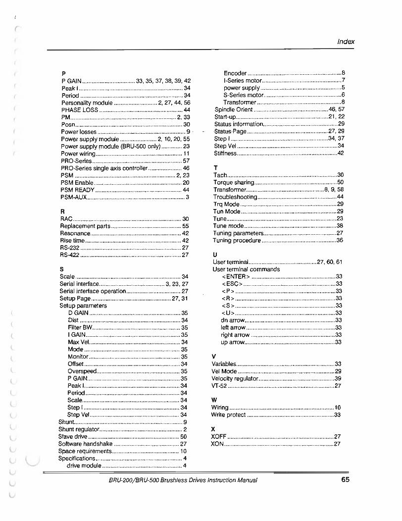
l
l
(
(
Index
p Encoder .......................................................... 8 P GAIN ................................. 33, 35, 37, 38, 39, 42 1-Series motor ....................... .......................... 7 Peak 1 .................................. ............................... 34 power supply .................................................. 5 Period ................................................................ 34 S-Series motor ................................................ 6 Personality module ........................... 2, 27, 44, 56 Transformer .................................................... 8 PHASE LOSS .................................................... 44 Spindle Orient .............................................. 46, 57 PM .................................................................. 2, 33 Start-up ......................................................... 21 , 22 Posn .............................................. .............. ....... 30 Status information .............................................. 29 Power losses ..................... _ ................................ 9 · ·- ·Status Page ................... ............................... 27, 29 Power supply module ....................... 2, 10, 20, 55 Step 1 •••.•••••.••••..•••• .•.•• .•.••.••••••...•••.••.••.•••••..••• 34, 37 Power supply module (BRU-500 only) ............. 23 Step Vel .............................................................. 34 Power w iring ...................................................... 11 Stiffness .............................................................. 42 PRO-Series ........................................................ 57 PRO-Series single axis controller ..................... 46 T PSM ............................................................... 2, 23 Tach .................................................................... 30 PSM Enable ....................................................... 20 Torque sharing ................................................... 50 PSM READY ...................................................... 44 Transformer ................ ................................ 8, 9, 58 PSM-AUX ............................................................. 3 Troubleshooting ................................................. 44
Trq Mode ............................................................ 29 R Tun Mode ........................................................... 29 RAC .................................................................... 30 Tune .................................................................... 23 Replacement parts ............................................ 55 Tune mode ......................................................... 38 Resonance ......................................................... 42 Tuning parameters ............................................. 27 Rise time ............................................................ 42 Tuning procedure .............................................. 36 RS-232 ............................................................... 27 RS-422 ............................................................... 27 u
User terminal. ......................................... 27, 60, 61 s User terminal commands Scale .................................................................. 34 <ENTER > .................................................... 33 Serial interface ......................................... 3, 23, 27 < ESC> ........ ................................................. 33 Serial interface operation .................................. 27 <P> .............................................................. 33 Setup Page .................................................. 27, 31 < R> .............................................................. 33 Setup parameters <S> .............................................................. 33
DGAIN ......................................................... 35 <U> ....................................... ....................... 33 Dist ............................................................... 34 dn arrow ........................................................ 33 FilterBW ....................................................... 35 left arrow ....................................................... 33 I GAIN ........................................................... 35 right arrow .................................................... 33 MaxVel.. ....................................................... 34 up arrow ........................................................ 33 Mode ............................................................ 35 Monitor ......................................................... 35 v Offset ............................................................ 34 Variables ............................................................. 33 Overspeed .................................................... 35 Vel Mode ............................................................ 29 PGAIN .......................................................... 35 Velocity regulator ............................................... 39 Peak 1 ............................................................ 34 VT-52 .................................................................. 27 Period ........................................................... 34 Scale ............................................................. 34 w Step 1 ............................................................ 34 Wiring ............................. .................................... 10 Step Vel ........................................................ 34 Write protect ...................................................... 33
Shunt. ................................................................... 9 Shunt regulator .................................................... 2 X Slave drive ......................................................... 50 XOFF .................................................................. 27 Software handshake ........................ ................. 27 XON .................................................................... 27 Space requirements .............. .. .......................... 10 Specifications ...................................................... 4
drive module .................................................. 4
BRU-200/ BRU-500 Brush/ess Drives Instruction Manual 65

I ( (
( ( (
\._
(
(
(
(
(
(
(
(
(
(
(
(
(
(
(
(
{
{
(
(
(
(
t l t l (._
(.
L l,.
G \...,.
u 0 (..,
0 '

(
(
L
Mail Or Fax: RELIANCE MOTION CONTROL Technical Support Group 6950 Washington A venue South Eden Prairie, MN 55344 Fax#: (612) 942-3636
Technical Writing Internal Use:
DIF #
RELIANCE MOTION CONTROL DOCUMENTATION IMPROVEMENT FORM
Manual Number: _________ _
Page Number(s): _________ _
Comments: (Please give chapters, page numbers or specific paragraphs that the change will affect. Include markups from the document or attach additional pages if necessary.)
What will this improvement suggestion provide? ____________________ _ _
Originator:------------Company: _ ________________ __
Address:
Technical Writing Internal Use:
Thank vou for your comments ...
City: _____ _ State: __ _ Zip: ___ _
Phone: -'----L----------------Date:
Follow-Up Action
MDTIDN CDNTRDL .. RELIANCE ELECTRIC: •0

BRU-200 and BRU-500Brushless DrivesInstruction Manual
P/N 0013-1028-001 Revision B
Reliance Motion Control, Inc. / 6950 Washington Avenue South / Eden Prairie, MN 55344 / 612-942-360 / 800-328-3983